Operation & Maintenance Manual
|
|
|
- May Stephens
- 5 years ago
- Views:
Transcription
1 Operation & Maintenance Manual

2 OPERATING AND MAINTENANCE PROCEDURES FOR THE NATURAL GAS SYSTEM OF SEVIER COUNTY UTILITY DISTRICT APPROVED BY: Executive Administrator Executive Administrator Executive Administrator Executive Administrator Date Date Date Date Executive Administrator Executive Administrator Date Date
3 SEVIER COUNTY UTILITY DISTRICT OPERATING AND MAINTENANCE PROCEDURES ANNUAL REVIEW SHEET YEAR ADMINISTRATOR SIGNATURE SHEET DATE 2011 (Plan was rewritten)
4 PREFACE This manual mandates operating, maintenance and emergency procedures for S C U D (Sevier County Utility District). All responsible personnel shall be trained in the procedures contained within this manual for the sole purpose of performing at the highest level obtainable. The appropriate personnel shall review this manual a minimum of once each calendar year not to exceed fifteen months. If revisions are necessary, new copies of this manual will be distributed.
5 INDEX General 1. System Pressures 2. System Monitoring 3. Odorization 4. Regulators 5. Reliefs 6. Corrosion Control 7. Record Keeping Procedures 8. Gas Odor & Leak Response 9. Governmental Reporting 10. Valves 11. Transmission Lines 12. Distribution Piping Installation & Maintenance 13. Test Requirements 14. Excess Flow Valves 15. Safety 16. Maintenance Records 17. Depth Of Burial 18. Emergency Procedures 19. Public Awareness 20. Uprating 21. MAOP 22. Customer Notification 23. Control Room Management 24. OQ 25. DIMP 26. Appendix 1 Contacts 27. Appendix 2 Forms 28. Appendix 3 Customer Notification 29. Appendix 4 Uncontrolled Release of Gas 30. Appendix 5 Welding and Fusion General Revisions
6 GENERAL The O & M manual, Procedures manual and Emergency Operations manual shall be made available to appropriate personnel. Construction records/documentation and maps, will be made available to appropriate personnel All responsible personnel shall be trained in the procedures contained within this manual for the sole purpose of performing at the highest level obtainable. S C U D shall periodically review and the work done by their employees to determine the effectiveness and adequacy of the procedures used in normal operation and maintenance and modify the procedures when deficiencies are found. Procedures will be reviewed and documented during supervisor meetings, other called employee meetings and inspections by supervisors.
7 1. SYSTEM PRESSURES General S C U D shall assess the pressure limitations of all segments of the gas distribution system and shall maintain up-to-date records and maps of the system. These limitations shall be based on class location, design, construction tests, condition tests, condition and history of the piping and shall comply with all applicable codes. Periodic reviews of the above criteria shall be conducted to insure that the limitations are sufficient. Operating pressures shall be classified and defined as follows: Distribution low pressure: 1-60 psig Distribution medium pressure: psig Distribution high pressure: psig S C U D shall operate the system in such a manner that operating pressures throughout the system conform to the criteria established by S C U D. All facilities shall be designed, constructed, operated and repaired as per Class 3 or Class 4 requirements as applicable, in accordance with the lasted edition of 49 CFR Part 192.5, Class Location. S C U D gas systems are supplied by East Tennessee Natural Gas pipeline at approximately 700 psig. The city gate stations reduce the pressure and deliver gas at a low, medium or high distribution pressure to the district regulator stations. The district regulator stations reduce the gas pressure to low distribution pressure. S C U D operates at less than 20% of SMYS. The MAOP establishment design criteria shall be noted and accepted under CFR 49, The gas distribution systems shall not operate in excess of the established Maximum Allowable Operating Pressure for each system. The description and operating perimeters of all regulator stations can be found in the S C U D Regulating & Metering Manual. Upon startup, re-instatement or turning gas onto a line for any reason, care must be taken so that the MAOP plus allowable build up is not exceeded. 1.2 SYSTEM PRESSURE CHANGES General Except as outlined in Section 10, "Valves", and Section 18, "Emergency Procedures", there shall be no system pressure changes without prior approval from the S C U D Measurement and/or Engineering Department. This will include, but is not limited to, valve operations, cutting of mains, squeezing off of mains and resetting regulator outlet pressures. In order to minimize service interruptions, maps shall be utilized in determining the sequence in which valves are to be checked and operated. Valve Operations Valves located in any main of the Gas Distribution system shall not be opened or closed without prior approval (see Section 10 Valves ). The default status of all underground valves is open. The status of a closed valve shall be maintained by the Engineering Department. District Regulator Stations No pressure changes shall be made on district regulator stations without prior approval from the S C U D Measurement and/or Engineering Department. The pressure setting of district regulator stations shall be
8 determined in accordance with the needs of the district and related to standards set forth in 1.1 of this section. These changes may be seasonal related. City Gate Stations There shall be no pressure changes at any city gate station without prior approval from the Measurement and/or Engineering Department.
9 2. SYSTEM MONITORING & General District regulator stations shall be equipped with recording gauges and/or telemetry equipment to monitor the gas pressure in the system. Telemetry communication is also currently utilized at the City Gate Station by East Tennessee Natural Gas. Selected pressures at strategic locations (check points) throughout the distribution system shall be accessible and conveyed to SCUD by electronic recorders and/or telemetry equipment to monitor the gas pressure in the system. The electronic recorders are downloaded and reviewed monthly for any abnormally high or low pressure conditions. Telemetry data is downloaded and available at the SCADA terminal located at the S C U D main office. High and low pressure alarms are initiated by the SCADA system. S C U D shall immediately respond to and investigate any abnormally high or low pressure conditions or alarms. Corrections shall be made as deemed necessary to return the system to normal operating conditions. 2.2 Maintenance of System Monitoring Equipment Pressure Transmitters: All transmitters shall be given a visual inspection, pressure check (at operating pressure) and calibrated if necessary, to coincide with the annual city gate and district regulator station inspections. Calibration of transmitters shall be done as needed with a minimum frequency of annually not to exceed 15 months at city gate stations and 36 months at district regulator stations. Pressure Recorders in the Field: Field recorders shall be calibrated as needed but at least every 36 months. Records shall be kept as to found and left conditions.
10 3. ODORIZATION All natural gas distributed to S C U D customers will be odorized sufficiently to be detectable at concentrations in air of 1/5 the lower explosive limit by a person with a normal sense of smell. To ensure proper odorant concentration, an odorant detection test shall be performed monthly at each check point using an odor detection instrument to determine the level at which the gas odor is detected. Odorization equipment at each city gate station shall be visually examined monthly for proper operation and appearance. For the S C U D gas system, approximately 0.5 to 0.75 pounds per MMCF of odorant level is injected in the system. Any abnormal condition(s) shall be corrected and documented. Inspections and maintenance shall be done in accordance with S C U D procedures.
11 4. REGULATORS Regulators must be of proper size and capacity and be properly installed and protected from dirt, liquids, or other conditions that might prevent proper operation. 4.1 City Gate and District Regulator Stations Annual Inspections Once each calendar year, at intervals not to exceed fifteen (15) months, each city gate station, district regulator station and accompanying equipment shall be inspected and tested. During the inspection, regulators will be inspected for lock off, controllers should fully open and close valves, and proper set points shall be verified. Appropriate steps shall be taken to correct or repair any malfunctions that are found. The inspection shall follow a procedural checklist which, upon completion, shall be dated and signed by the responsible personnel and recorded. Periodic Inspections City gate stations and district regulator stations shall be visually checked anytime a measurement department employee visits a station. Any abnormal condition found shall be either corrected or scheduled for repair, as appropriate. 4.2 Large Commercial and Industrial Regulators Regulators supplying large commercial and industrial pressure customers shall be inspected a minimum of once each calendar year. Regulators owned by the customer are not subject to inspection or maintenance by S C U D. 4.3 Small Commercial and Residential Regulators Whenever possible, without entering the customers building, each regulator supplying small commercial and residential customers shall be inspected for proper operation each time the customer's gas meter or regulator is changed or serviced.
12 5. RELIEFS &.199 &.201 &.743 Safety Relief Valves Safety Relief Valves must be of proper size and capacity and be properly installed and protected from dirt, liquids, or other conditions that might prevent proper operation. Safety relief valves at city gate stations and district regulator stations shall be inspected once each year, at intervals not to exceed fifteen (15) months. The set point of the relief valve shall be confirmed at the time of the annual inspection. Relief settings shall be established at and not exceed10% above delivery pressure. S C U D will review the calculated required capacity of those relief devices protecting the distribution system and compare calculations with the rated capacity of the regulator. Any problems found will be corrected. All relief valve stacks shall include a manual cut-off valve upstream of the relief valve and shall be locked in the open position. Safety relief valves at customer metering facilities which are owned by S C U D shall be given a visual inspection each time the regulator is inspected. Set point confirmations or capacity determinations of such relief device are not required. Relief devices owned by the customer are not subject to inspection and maintenance by S C U D.
13 6. CORROSION CONTROL General Buried steel gas piping must have an external protective coating. Each external protective coating, whether conductive or insulating, applied for the purpose of external corrosion control must (1) Be applied on a properly prepared surface; (2) Have sufficient adhesion to the metal surface to effectively resist underfilm migration of moisture; (3) Be sufficiently ductile to resist cracking; (4) Have sufficient strength to resist damage due to handling and soil stress; and, (5) Have properties compatible with any supplemental cathodic protection. (a) Each external protective coating which is an electrically insulating type must also have low moisture absorption and high electrical resistance. (b) Each external protective coating must be inspected just prior to lowering the pipe into the ditch and backfilling, and any damage detrimental to effective corrosion control must be repaired. (c) Each external protective coating must be protected from damage resulting from adverse ditch conditions or damage from supporting blocks. (d) If coated pipe is installed by boring, driving, or other similar method, precautions must be taken to minimize damage to the coating during installation Within one year of completion of construction of such piping, a cathodic protection system designed to adequately protect the installed piping from external corrosion shall be installed and placed in operation. Steel piping in the S C U D system is protected by a mill applied coating, galvanic anodes and impressed current rectifiers. Where piping is cathodically protected, field tests and surveys shall be conducted to verify adequate protection. Records of tests, surveys, and other important information shall be maintained by S C U D. This information must include the following: Assurance that, complete electrical isolation of the protected piping from foreign structures, including casings, has been accomplished. Pipe casing isolation shall be verified by potential tests, pipe locator or other methods. Electrical continuity must have been achieved for each segment of piping protected as a unit. Continuity shall be verified by pipe-to-soil potential surveys. Where continuity cannot be verified by potential surveys, the pipe locator shall be used as verification equipment. A pipe-to-soil potential survey of the piping, including all applicable components, laterals and extremities, shall be conducted and must indicate a cathodic potential of at least volts to the copper-copper sulfate reference half-cell. Various points must be surveyed to assure adequate coverage of the piping. The cathodic protection system shall be designed and installed to minimize any adverse effects on existing, adjacent, underground structures. When foreign interference which may affect protected piping or structures is found to exist, corrective measures must be taken to minimize and monitor the effects of such interference. Cathodic protection shall be installed and maintained in accordance with S C U D procedures. When potential surveys, tests or inspections, indicate an unacceptable level of protection, prompt action shall be initiated and continued until an acceptable level of protection is obtained.
14 6.2 Monitoring Cathodic Protection When tests and surveys of the cathodically protected system indicate an adequate level of protection has been achieved (a negative Cathodic voltage of at least.85 volts with reference to a saturated coppercopper sulfate half-cell), scheduled surveillance of the piping shall be initiated. This must include inspections of cathodic protection facilities and pipe-to-soil potential surveys conducted at various locations designated as routine check or test stations. A sufficient number of such points shall be selected to provide reasonable coverage of the protected area and must be so located that periodic potential tests will reflect the level of protection received by the piping in that area. S C U D shall review each area periodically and where necessary, adjust the monitoring system to reflect changes in the area's piping system. To ensure an effective and continuous level of protection, the following monitoring schedule shall be adhered to: Impressed Current Areas Bimonthly - Inspect rectifier and check rectifier voltage and current outputs six (6) times each calendar year with intervals not to exceed 2-1/2 months. Annually - Potential survey at all test stations within all areas of the S C U D Systems shall be tested once each calendar year with intervals not to exceed fifteen (15) months. Maintenance on test leads will be done during the annual inspection and/or as needed throughout the year. Galvanic Anode Areas Annually - Potential survey at all test stations within each area once each calendar year with intervals not to exceed fifteen (15) months. Isolated Main Sections (not in excess of 100 feet) Annually A pipe to soil potential survey shall be conducted each year on a minimum of ten (10) percent of such sections distributed over the entire system. Surveys must be scheduled in such a manner that a different ten percent will be tested each calendar year so that all sections will have been tested at least once in each ten (10) year period. Isolated Services and Components Annually - Potential survey of not less than ten percent of isolated services and components distributed over the entire system. Surveys must be scheduled in such a manner that a different ten percent will be tested each calendar year so that all such services and components will be tested at least once in each ten-year period. Casings Annually Perform Potential Survey of metallic casings and the steel piping passing through the casing. If the two readings at a location are similar, additional inspections and tests may be made to determine whether the line pipe is electrically isolated from, or shorted to, the casing. When the readings or tests show the casing to be shorted to the line pipe, one of the following courses of action must be followed and performed by S C U D or a contracted Corrosion Control Technician: Clear the short. Monitor the casing with leak detection instruments at intervals not exceeding 4-1/2 6.3 Location of Piping in Relation to Electric Transmission Lines Procedures for the initial protection of piping outlined in this section shall also apply to piping located in the area of electric transmission lines. Monitoring of such piping shall be conducted annually. Routine surveys of piping subjected to induced voltages due to unbalanced line or fault currents shall be conducted only under suitable weather conditions. During surveys or maintenance, only one anode or anode bed shall be disconnected from the pipe at a time so as to maintain grounding for induced voltages. Trouble shooting of piping subjected to induced voltages shall be carried out by a third party NACE certified corrosion control contractor. When it becomes necessary that the pipe be cut, a bonding conductor shall be attached to the pipe across the point of separation to maintain electrical continuity.
15 Piping and insulating flanges located in the area of electric transmission lines shall be protected from damage by fault currents or lightning. Protective measures include anodes, grounding cells, zinc ribbon and insulation kits (unions, sleeves and gaskets). 6.4 Monitoring Corrosion &.477 &.481 Atmospheric Corrosion &.481 Above ground natural gas piping exposed to the atmosphere and installed after July 31, 1971 shall be visually inspected at least once every 3 years not to exceed 39 months. If atmospheric corrosion exists on above ground metallic piping, then remedial action shall be taken to protect the integrity of the material. Close inspection should be made where clamps, rest plates, sleeved openings, pipe at soil-to-air interfaces, under thermal insulation, under dis-bonded coatings, at pipe supports, in splash zones, at deck penetrations, and in spans over water. Corrosion surfaces shall be properly cleaned and stripped of all active corrosion and properly prepared for coated using approved coating and protective materials. Visual Inspection of Steel Piping NEW- The coating on steel piping that is to be buried shall be inspected by the construction crew prior to lowering and backfilling to insure that no damage has occurred that would be destructive to corrosion control. If damage is found, the coating shall be repaired by manufacturer approved methods. EXPOSED- Buried piping which has been intentionally uncovered or otherwise known to be exposed shall be examined by the excavating crew for evidence of external corrosion and/or coating defects. General corrosion. Except for cast iron or ductile iron pipe, each segment of generally corroded distribution line pipe with a remaining wall thickness less than that required for the MAOP of the pipeline, or a remaining wall thickness less than 30 percent of the nominal wall thickness, must be replaced. However, corroded pipe may be repaired by a method that reliable engineering tests and analyses show can permanently restore the serviceability of the pipe. Corrosion pitting so closely grouped as to affect the overall strength of the pipe is considered general corrosion for the purpose of this paragraph. Localized corrosion pitting. Except for cast iron or ductile iron pipe, each segment of distribution line pipe with localized corrosion pitting to a degree where leakage might result must be replaced or repaired. If external corrosion requiring remedial action under 49 CFR through is found, the operator shall investigate the immediate surface and length beyond the exposed portion (by visual examination) to determine whether additional corrosion requiring action exists in the vicinity of the exposed portion. All actions shall be in accordance with S C U D procedures and recorded. Internal Corrosion &.477 Whenever any pipe (segment or coupon) is removed from the system for any reason, the internal surface must be inspected for evidence of corrosion. If internal corrosion is found, then adjacent pipe must be investigated to determine the extent of the internal corrosion. Natural gas containing more than 0.25 grain of hydrogen sulfide per 100 standard cubic feet (4 parts -per-million) may not be stored in pipe type or bottle type holders. Provisions shall be made to monitor internal corrosion if the natural gas stream contains more than 0.25 grain of hydrogen sulfide per 100 standard cubic feet (4 parts -per-million). Gas analysis is received and reviewed annually from the gas supplier for compliance of the above.
16 6.5 Corrosion Control Records All records relating to the operation, maintenance and effectiveness of the cathodic protection system shall be retained by S C U D for a minimum of 5 years or the life of the facilities, whichever is longer? Records must include data pertaining to all locations, tests, surveys, inspections and maintenance to demonstrate the adequacy of corrosion control measures or that a corrosive condition does not exist.
17 7. RECORD KEEPING PROCEDURES 7.1 General The following records shall be maintained on all new underground piping system installations and repairs and/or changes to existing underground piping systems in detail for the life of the pipeline or at least 5 years whichever is longer, to provide historical information, physical location, design ratings, and any other data necessary for the safe and continuous operation and maintenance by S C U D. 7.2 Gas Distribution Mains S C U D shall review and update system maps on a regular basis. Completion reports for new installations, repairs or replacements shall be stored as a permanent record for the life of each gas main. All new or replaced mains shall be surveyed and added to the GIS system map. 7.3 Patrols and Leak Surveys S C U D shall maintain records of distribution pipeline patrols and leakage surveys in accordance with & 723 and S C U D procedures. 7.4 Underground Valves Distribution valves shall be plotted on gas system maps indicating size, type, and location of each valve. The inspection and maintenance records of all valves will be maintained as specified in Section 10 of this manual. 7.5 Services Completion reports (service orders) showing size, type, tap location, valve location, corrosion control facilities and pressure tests of each service shall be recorded as a permanent record and maintained in the GIS. 7.6 Meters S C U D shall maintain records on each gas meter for the life of the meter. Records shall include but not be limited to the following: 1. Locations 2. Date of installation and removal 3. Service order when installed and removed 4. Maintenance performed on the gas meter 7.7 Regulators and Relief Valves S C U D shall keep updated drawings of all city gate stations, district regulator stations, and large industrial regulator installations. All data showing make, type, serial number, inner valve size, set pressures, relief settings etc. and a record of all inspections and maintenance. 7.8 Odorization Records of the periodic sniff test used to determine effectiveness of odorization shall be kept on file for at least one (1) year. 7.9 Leaks S C U D shall keep a record of all reported or discovered leaks and the disposition of each leak reported in accordance with the procedure set forth in CFR and Sections 7 & 12 of this manual.
18 7.10 Operator Qualification S C U D employees performing covered task shall be qualified under an Operator Qualification program. Operator Qualification records shall be maintained by SCUD. Contractors performing covered tasks for S C U D, shall provide proof of qualification under their own Operator Qualification program or be qualified by S C U D.
19 8. GAS ODOR & LEAK RESPONSE &.616 &.723 Procedures for advising customers and the general public in recognizing gas odors, leaks and emergency conditions, and the reporting of such conditions to the appropriate officials shall be developed and maintained. CFR 49, Provisions for receiving reports of gas odors, leaks and emergency conditions shall be maintained twentyfour (24) hours a day, seven (7) days a week. After working hours, on weekends and holidays, reports will be received and relayed to S C U D by an answering service. Upon receiving a report of a gas odor, leak or emergency condition, the necessary information will be obtained and relayed to an S C U D representative, who must investigate the call as soon as possible, in accordance with S C U D procedures to determine if any corrective action is required. Employees involved with responding to gas odors, leaks and emergency conditions, shall be trained and qualified in the appropriate procedures.
20 9. GOVERNMENTAL REPORTING &.5 &.7 & General An incident as defined below, must be reported at the earliest practical moment following discovery. It must be reported to the Pipeline and Hazardous Materials Safety Administration (PHMSA) at the NATIONAL RESPONSE CENTER (WASHINGTON, D.C.). The report may be filed electronically at or telephonically at Tennessee Regulatory Authority (TRA), must also be notified both by phone and in writing. Incident Definition - Any event that involves a release of gas from a pipeline that results in any of the following: 1. A death or personal injury requiring in patient hospitalization (must be confirmed) 2. Estimated property damage of $50,000 or more, including loss to S C U D and others or both, but excluding the cost of lost gas. 3. Unintentional estimated gas loss of 3 million cubic feet of gas or more. 4. An event that is significant, in the judgment of Sevier County Utility District, even though it did not meet the previous criteria. Gathering the required information to be facilitated shall fall to each department head, upon which each shall establish and implement detailed procedures for obtaining and transmitting required data to the appropriate areas. The following information shall be reported: 1. Name and appropriate phone numbers of S C U D and person(s) making report. 2. The location of the incident. 3. The time of the incident. 4. The number of fatalities and personal injuries, if any. 5. All other significant facts that are known by S C U D that is relevant to the cause of the incident or extent of the damages. The electronic or telephonic report will be made by the S C U D president or vice-president. If the president or vice-president is unavailable, the next available responsible person shall make the report. 9.2 Written Reports &.9 A follow up report, (DOT form ) will be submitted to PHMSA and TRA as soon as practicable time allows but not exceeding thirty (30) days following the incident. Reports to PHMSA must be filed electronically at unless an alternative method is authorized. Written reports must be sent to: Office of Pipeline Safety, Pipeline and Hazardous Materials Safety Administration, U.S. Department of Transportation, the Information Resources Manager, PHP New Jersey Avenue, SE, Washington DC Gathering the required information to be facilitated shall fall to each department head, upon which each shall establish and implement detailed procedures for obtaining and transmitting required data to the appropriate areas.
21 The responsible personnel repairing the leak shall prepare the required reports and forward them to the S C U D president or vice-president. Any additional relevant information gathered about an incident after the initial report has been filed, will be filed in a supplemental report or reports that reference the initial report and incident by date and subject. 9.3 Distribution System: Annual Report & Mechanical Fitting Failure Reports &.12 S C U D shall submit an annual report online via the PHMSA Portal on the Department of Transportation Form RSPA F This report must be submitted not later than March 15, for the preceding calendar year. Each mechanical fitting failure, as required by Integrity management in , will be submitted by SCUD online via the PHMSA Portal on a Mechanical Fitting Failure Report Form PHMSA F SCUD shall submit a mechanical fitting failure report for each mechanical fitting failure that occurs within a calendar year not later than March 15 of the following year. 9.4 Recognizing and Reporting Safety Related Hazardous Conditions &.25 S C U D employees engaged in the operation and/or maintenance of the gas facilities shall report to their supervisor/foreman, conditions which constitute, or if allowed to continue, will constitute a potential hazard to life or property. (See the Safety Related Conditions listed below). S C U D management must file a report and the report must be filed (received by the Associate Administrator, OPS) in writing within five (5) working days after the day the safety related hazardous condition is determined to exist, but no later than ten (10) days after the day the condition was discovered. Separate conditions may be described in a single report if they are closely related. Reports may be transmitted by facsimile at (202) Safety related hazardous conditions include: 1. In the case of a pipeline that operates at a hoop stress of 20 percent or more of its specified minimum yield strength (SMYS), general corrosion that has reduced the wall thickness to less than that required for the maximum allowable operating pressure, and localized corrosion pitting to a degree where leakage might result. 2. Unintended movement or abnormal loading by environmental causes, such as an earthquake, landslide, or flood, that impairs the serviceability of a pipeline.9 - Repr 3. Any material defect or physical damage that impairs the serviceability of a pipeline that operates at a hoop stress of 20 percent or more of its specified minimum yield strength. 4. Any malfunction or operating error that causes the pressure of a pipeline to rise above its maximum allowable operating pressure plus the build-up allowed for operation of pressure limiting or control devices. 5. A leak in a pipeline that constitutes an emergency. 6. Any safety-related condition that could lead to an imminent hazard and causes (either directly or indirectly by remedial action of the operator), for purposes other than abandonment, a 20 percent or more reduction in operating pressure or shutdown of operation of a pipeline. S C U D currently does not operate any pipelines at 20% SMYS or above. S C U D does not use, store, distribute or transport LNG. Safety Related Conditions not requiring reporting includes: 1. A condition on a master meter system or customer owned service line. 2. A condition that becomes an incident before the reporting deadline for filing a safety related hazardous condition report.
22 3. A condition on a pipeline that is located more than 220 yards from any building for human occupancy or outdoor place of assembly and does not lie within a active railroad, street, highway, or paved road right-of-way. 4. A condition that is corrected by repair or replacement before the deadline for filing a safety related hazardous condition report. 5. A condition where corrosion is localized on coated or catholically protected pipe and is repaired or replaced before the deadline for filing a safety related hazardous condition report. The report must be headed Safety-Related Condition Report and contain the following information: 1. Name and principal address of operator. 2. Date of report. 3. Name, job title, and business telephone number of person submitting the report. 4. Name, job title, and business telephone number of person who determined that the condition exists. 5. Date condition was discovered and date condition was first determined to exist. 6. Location of condition, with reference to the State (and town, city, or county) or offshore site, and as appropriate, nearest street address, offshore platform, survey station number, milepost, landmark, or name of pipeline. 7. Description of the condition, including circumstances leading to its discovery, any significant effects of the condition on safety, and the name of the commodity transported or stored. 8. The corrective action taken (including reduction of pressure or shutdown) before the report is submitted and the planned follow-up future corrective action, including the anticipated schedule for starting and concluding such action
23 10 VALVES & Maintenance The following valves shall be inspected, serviced, and operated annually, not to exceed 15 months, without interfering with the operation of the system. (Valves on the end of a gas line that are to be used for future extension are not included.) A. UNDERGROUND VALVES: 1. Valves on the inlet and outlet lines to city gate and district regulator stations 2. Valves on a main line. 3. Valves on large commercial or industrial service lines. 4. Valves on inlet lines to farm taps. B. ABOVE GROUND VALVES IN CITY GATE AND DISTRICT REGULATOR STATIONS: 1. Valves on meter runs. 2. Valves on the inlet and outlet lines. 3. Valves on station bypasses. 4. Valves on regulating runs 5. Block valves on relief stacks. C. ANY OTHER VALVES WHICH ARE DEEMED CRITICAL IN THE EVENT OF AN EMERGENCY. Valves listed above shall be inspected annually not to exceed 15 months. Meter set block valves and meter stops shall be inspected and serviced as needed. Valve maintenance shall be done in accordance with procedures found in the S C U D Procedures Manual. D. Meter stops turned off for any reason and left unmanned must be locked off.
24 11 TRANSMISSION LINES S C U D does not operate or maintain any transmission lines.
25 12 DISTRIBUTION PIPING INSTALLATION & MAINTENANCE Distribution gas lines installed or repaired shall be done in accordance with this manual and the S C U D Procedures Manual. See Appendix 5 of this manual for Welding and Fusion General Information. See Section 17 for Depth of Cover. Procedures will be reviewed during supervisor meetings, other called employee meetings and inspections by supervisors Surveillance S C U D shall use continued surveillance of its facilities to determine and take appropriate action concerning changes in class location, failures, leakage history, corrosion, substantial changes in cathodic protection requirements, and other unusual operating and maintenance conditions. Surveillance is accomplished thru: Patrolling, Exposed Pipe Reports, Cathodic Protection Survey and Leak Survey. If a segment of pipe is determined to be in unsatisfactory condition, the segment will be replaced or abandoned instead of lowering the MAOP A. Patrolling The frequency of patrolling shall be determined by the severity of the condition which could cause failure or leakage and the consequent hazards to public safety. S C U D shall keep records on all mains located in places or on structures where potential physical movement or external loading could cause failure or leakage. Mains subject to anticipated movement or external loading which may result in failure or leakage will be patrolled at least at quarterly intervals (4 times a year) not exceeding 4 ½ months for inside business districts and at least 2 times a year not to exceed 7 ½ months for outside business districts. (Example - Bridge Crossings) Movement external loading shall be defined as: vibration, vehicular impact, earth movement, future excavations, washouts, floods, unstable soil, landslides, areas where piping support may have been weakened by outside third party construction of other utilities and where hazards that may cause the pipe to move or to be subjected to abnormal loads. B. Exposed Pipe Reports Reports are filled out whenever steel pipe is exposed, noting the condition of the pipe and coating. See Appendix? C. Cathodic Protection Survey A cathodic survey is perform annually. See section 6 of this O & M manual. D. Leak Survey Leak Surveys will be conducted annually in accordance with Each leak will be documented for the purpose of repair and maintenance. S C U D utilizes GIS to develop and maintain a map depicting the boundaries of the business and non-business districts. Business Districts will be surveyed using gas detection equipment on an annual basis not to exceed fifteen (15) months. Business Districts include: 1. Areas where the majority of building on either side of the street are utilized for business use, such as retail, wholesale, office, or service. 2. Area where the majority of building on either side of the street are high occupancy multi-story buildings with multiple businesses that share common walls.
26 3. Area where gas facilities are under continuous paving that extends from the center line of the street to the building wall. 4. Buildings that regularly accommodate more than one hundred (100) people for economic, educational, health, religious, recreational, entertainment or dining purposes. Non-Business districts are all areas not included in the business districts. These areas will be surveyed with gas detection equipment, on a rotating annual basis so that all non-business districts will be surveyed at least once every five (5) years not to exceed sixty-three (63) months. Each gas meter must be leak surveyed during the appropriate leak survey Leak Classification & Management The following leak classifications are to be used by S C U D Employees when grading a gas leak. The leaks will be graded in accordance with leak classification criteria in the S C U D procedures manual. Grade 1 Leaks -This classification shall designate a leakage condition which, due to its location and/or relative hazard potential, shall require immediate corrective action until the hazardous condition no longer exist. The leak shall then be scheduled for immediate repair activity. Grade "1" leaks include, but are not limited to: 1. Any leak which, in the judgment of the representative at the scene, is regarded as potentially hazardous. 2. Any indication of gas entering a building or tunnel. 3. Any gas reading from a CGI (combustible gas indicator), in a substructure where gas could migrate inside or to the outside wall of a building. Such as: manhole, vault, water meter box, catch basin, etc Any gas reading from a CGI (combustible gas indicator), at or below ground level, within five (5) feet of the foundation wall of a building which, in the judgment of the Gas Operator, is potentially dangerous. 5. Any reading from a CGI (combustible gas indicator), of 3% gas or greater, in a confined space. 6. Any reading from a CGI (combustible gas indicator) of 3% gas or greater, one (1) foot or higher above the ground or surface, in an area accessible by anyone other than a S C U D representative. 7. Blowing Gas. 8. Leaking gas that has ignited. Grade 2 - Leaks - This classification shall designate a leakage condition which, due to its location and/or relative hazard potential, does not require immediate attention, but shall be scheduled and repaired within six (6) months unless the line is to be replaced or abandoned. The replacement or abandonment must be completed within twelve (12) months. If the leak is not repaired within six (6) months, it must be rechecked at intervals not to exceed six (6) months. Grade 2 leaks include, but are not limited to: 1. Any leak not reaching any of the Grade 1 Leak criteria but in the judgment of the S C U D representative on the scene justifies scheduling repair. 2. A reading from a CGI (combustible gas indicator), of greater than 1% gas but less than 3% gas, one (1) foot or higher above the ground or surface. 3. A reading from a CGI (combustible gas indicator), of less than 3% gas, in a confined space. 4. A reading from a CGI (combustible gas indicator), of 1.5% gas or greater, at multiple locations more than three (3) feet apart, at the surface, edge or ground along a sidewalk but reading less than 3% gas, at a height of one (1) foot or higher above the ground or surface.
27 5. A reading from a CGI (combustible gas indicator), of 4% gas or greater, at multiple locations more than three (3) feet apart, at the surface, edge or ground along a road but reading less than 3% gas at a height of one (1) foot or higher above the ground or surface. Grade 3 Leak- This classification shall designate a leak condition that does not meet any of the requirements for a Grade 1 or Grade 2 leak. A Grade 3 leak shall be monitored at least once every twelve (12) months to determine the current condition of the leakage Repair of Mains and Services &.311 Anytime any type of work is to be done on or with a line with gas on it, the hazard of fire or explosion must be reduced by: A. The removal of ignition sources in the presence of gas B. Providing a fire extinguisher or fire dept. C. Preventing welding or cutting on a pipeline containing a combustible mixture D. Post warning signs or monitoring and securing the site. Excavations 5 feet deep or deeper must be properly sloped or protected and air quality checked before entering. The maintenance of mains and services shall consist of testing, repair, protection and replacement of the component parts. Pipe must be pretested or pressure tested after being installed. Plastic pipe and/or insert tubing designed and installed in accordance with industry construction standards and procedures may be used as a method of replacement for steel mains and services. Temporary or permanent repairs shall be made on all lines that have a leak, corrosion pitting or other imperfection or that receive damage, which in the judgment of the S C U D representative would endanger the public. When temporary repairs are used, permanent repairs shall be made as soon as possible. Mechanical fittings shall not be used as a permanent repair. New and permanently repaired pipe must be fused or welded. Heat may not be applied with an open flame or torch. Repairs shall be pressure tested and/or tested with soap Abandonment and Deactivation of Facilities Abandonment of Facilities: Facilities to be abandoned will be disconnected from all gas sources, purged and the ends of the pipe sealed. Purging will be done in accordance with S C U D purging procedures. The ends of the pipe shall be capped or welded closed. Valve boxes shall be removed or the value lid removed and the stand pipe filled with a suitable compacted material. Deactivation of Services: Whenever service to a customer is discontinued and the meter and/or service riser is left in place, the valve on the service riser shall be locked off Tapping Pipelines Under Pressure Tapping must be done in accordance with manufacturer and S C U D procedures. See S C U D Procedures Manual. Anytime any type of work is to be done on or with a line with gas on it, the hazard of fire or explosion must be reduced by: A. The removal of ignition sources in the presence of gas B. Providing a fire extinguisher or fire dept. C. Preventing welding or cutting on a pipeline containing a combustible mixture D. Post warning signs or monitoring and securing the site Purging All purging must be done in accordance with S C U D procedures. See S C U D Procedures Manual.
28 13 TEST REQUIREMENTS All pressure tests must be documented and the records maintained. Steel: Each new, replacement or reinstated up rated steel main or service shall be pressured tested at a minimum pressure of 90 psig or 1.5 times the expected MAOP whichever is greater and a maximum pressure of 1.5 times 20% SMYS. After allowing time for temperature stabilization of the test material used, the test must be observed for a minimum of 15 minutes for service lines and 2 hours for mains. In case where it would not create and undue delay in the completion of the job, the test should be left for longer periods of time. The test duration will ensure the discovery of any leaks. Plastic (PE): New, replacement, and reinstated plastic services shall be pressure tested at a minimum pressure of 90 psig and the maximum test pressure may not be more than three times the design pressure (60 psig for S C U D s distribution system) at a temperature not less than the pipe temperature during the test. After allowing time for temperature stabilization of the test material used, the test must be observed for a minimum of 15 minutes for service lines and 2 hours for mains. In cases where it would not create an undue delay in the completion of the job, the test should be left for longer periods of time. The test duration will ensure the discovery of any leaks. Any service line that is temporarily disconnected must be tested the same as a new service line from the point of disconnection to the meter stop before reconnecting. However, if provisions are made to maintain continuous service, such as by installation of a bypass, any part of the original service line used to maintain continuous service need not be tested.
29 14 EXCESS FLOW VALVES (EFVs) & 385 The United States DOT required gas distribution utilities to have an EFV program effective February 3, Since then, Congress has specified in the 2006 Pipeline Safety (PIPES) Act that all operators of gas distribution systems install EFVs in SFR (Single Family Residence) services in lieu of customer notification. This change went into effect in June In April 2017, The United States DOT expanded the use of EFVs to branch service SFRs and some commercial services, effective April 14, The applicable DOT requirement is 49 CFR EFVs are spring operated and control the flow of gas through a service line when the flow rate exceeds a predetermined quantity. EFVs must perform to the requirements of 49 CFR As such, careful sizing of the EFV is critical. EFVs are typically installed in a coupling and activate when a gas service line is severed due to a dig-in. All EFVs supplied must meet the requirements of ASTM F and ASTM F The EFV has a bleed-by mechanism that will reopen the EFV when the pressure on both sides equalizes. S C U D will give all customers notice of the option to request an EFV installation, except where such installation is not required under (c) (i.e., where the service line does not operate at a pressure of 10 psig or greater through the year, the operator has experienced contaminants in the gas stream that could interfere with EFV operation, an EFV could interfere with operation and maintenance activities, or an EFV meeting performance standards in is not available). EFVs shall be installed on the following types of services with a main pressure greater than or equal to 10 psig. Install EFVs on services as close as practical to the main. (1) A single service line to one Single Family Residence (SFR); (2) A branched service line to a SFR installed concurrently with the primary SFR service line (i.e., a single EFV may be installed to protect both service lines); (3) A branched service line to a SFR installed off a previously installed SFR service line that does not contain an EFV; (4) Multifamily residences with known customer loads not exceeding 1,000 SCFH per service, at time of service installation based on installed meter capacity, and (5) A single, small commercial customer served by a single service line with a known customer load not exceeding 1,000 SCFH, at the time of meter installation, based on installed meter capacity. The EFV shall be sized and installed in accordance with the manufacturer s charts and instructions. The EFV must be sized to handle the expected gas load it will be supplying. The excess flow valve shall be located as close to the main or lateral as practical. The EFV, service line and/or riser shall be documented and mapped to identify the presence of an excess flow valve. Exceptions: S C U D need not install an excess flow valve if one or more of the following conditions are present: (1) The service line does not operate at a pressure of 10 psig or greater throughout the year; (2) The operator has prior experience with contaminants in the gas stream that could interfere with the EFV's operation or cause loss of service to a customer; (3) An EFV could interfere with necessary operation or maintenance activities, such as blowing liquids from the line; or (4) An EFV meeting the performance standards in is not commercially available to the operator.
30 S C U D must install either a manual service line shut-off valve or, if possible, based on sound engineering analysis and availability, an EFV for any new or replaced service line with installed meter capacity exceeding 1,000 SCFH.
31 15 SAFETY Precautions shall be taken to ensure the safety of S C U D employees and the public as well as property. Areas of safety include but are not limited to: 1. Personal Protective Equipment (PPE) Hard Hat, Vest, Safety Glasses, etc 2. Signage and Traffic and Pedestrian Control - (In accordance with the Manual on Uniform Traffic Control Devices) 3. Control of Ignition Sources - Anytime any type of work is to be done on or with a line with gas on it, the hazard of fire or explosion must be reduced by: a) The removal of ignition sources in the presence of gas b) Providing a fire extinguisher or fire dept. c) Preventing welding or cutting on a pipeline containing a combustible mixture d) Post warning signs or monitoring and securing the site. e) Static Suppression 4. Excavation Safety - Excavations 5 feet deep or deeper must be properly sloped or protected and air quality checked before entering. 5. Vehicle and Equipment Operation Procedures to ensure safety can be found in the S C U D Procedures Manual
32 16. MAINTENANCE RECORDS These specifications are covered under Section 7, "Record Keeping Procedures".
33 17. DEPTH OF BURIAL & Distribution Mains Gas distribution mains must be installed with a minimum of twenty-four inches (24") cover in accordance with CFR 49/DOT All depths specified in this standard meet or exceed the required twenty-four inches (24") minimum cover for distribution mains. Where an underground structure prevents the installation of a distribution main with the minimum cover, the main may be installed with less cover if it is provided with additional protection to withstand anticipated external loads. Such installations cannot be made without prior approval of proper S C U D authority. Any additional protective material shall not be in direct contact with the gas main Service Lines Gas service lines must be installed with a minimum of 12 inches (12 ) cover on private property and at least 18 inches (18 ) of cover in streets and roads in accordance with CFR 49/ DOT However, where an underground structure prevents installation at those depths, the service line must be able to withstand any anticipated external loads.
34 18. EMERGENCY PROCEDURES General S C U D shall provide employees involved in emergency response, access to the Emergency Operations Manual and Emergency Procedures. Employees involved with responding to gas emergency conditions, shall be trained and qualified in the appropriate procedures. S C U D shall review and document, activities to verify the effectiveness of the training and emergency procedures. Since the uncontrolled and unwanted release of natural gas could result in situations hazardous to life and property, the following emergency procedures are established to bring the emergency under control in the shortest possible time and with a minimum of customer outage. In all emergency situations, the protection of life should always receive priority over the protection of property. Care must be taken to secure the scene and extinguish ignition sources Recognizing Safety Related Hazardous Conditions S C U D employees engaged in the operation and/or maintenance of the gas facilities shall report to their supervisor/foreman, conditions which constitute, or if allowed to continue, will constitute a potential hazard to life or property. (See the Safety Related Conditions listed below). S C U D management must file a report and the report must be filed (received by the Associate Administrator, OPS) in writing within five (5) working days after the day the safety related hazardous condition is determined to exist, but no later than ten (10) days after the day the condition was discovered. Separate conditions may be described in a single report if they are closely related. Reports may be transmitted by facsimile at (202) Safety related hazardous conditions include: 1. Unintended movement or abnormal loading by environmental causes, such as an earthquake, landslide, or flood, that impairs the serviceability of a pipeline. 2. Any malfunction or operating error that causes the pressure of a pipeline to rise above its maximum allowable operating pressure plus the build-up allowed for operation of pressure limiting or control devices. 3. A leak in a pipeline that constitutes an emergency. 4. Any safety-related condition that could lead to an imminent hazard and causes (either directly or indirectly by remedial action of the operator), for purposes other than abandonment, a 20 percent or more reduction in operating pressure or shutdown of operation of a pipeline. SCUD currently does not operate any pipelines at 20% SMYS or above. SCUD does not use, store, distribute or transport LNG. Safety Related Conditions not requiring reporting includes: 1. A condition on a master meter system or customer owned service line. 2. A condition that becomes an incident before the reporting deadline for filing a safety related hazardous condition report. 3. A condition on a pipeline that is located more than 220 yards from any building for human occupancy or outdoor place of assembly and does not lie within an active railroad, street, highway, or paved road right-of-way. 4. A condition that is corrected by repair or replacement before the deadline for filing a safety related hazardous condition report. 5. A condition where corrosion is localized on coated or catholically protected pipe and is repaired or replaced before the deadline for filing a safety related hazardous condition report.
35 18.3 Definition of Emergency As used in these procedures, the word "emergency" shall include but not be limited to the following definitions: 1. The continued safe operation of a major segment of the gas distribution system is endangered, or 2. A gas leak (ignited or not) is of such magnitude that major roads or highways must be closed, or 3. A failure or malfunction of S C U D Natural Gas System exists that: a. Affects a large number of customers or imposes a danger to life and health of such magnitude that mobilization of all available emergency forces is required, or b. Necessitates immediate action to prevent or lessen property damage or save lives. 4. A fire and/or explosion have occurred near, or directly involve, the S C U D Natural Gas System. 5. A natural disaster has occurred. Some of these situations may require invoking the Emergency Call Lists, and/or may be reportable to the TRA or PHMSA Location of Equipment and Materials (See S C U D Emergency Procedures Manual) Any equipment and materials that may be necessary in an emergency shall be made available at the S C U D OC. Any good neighbor policy or a Mutual Assistance agreement between gas systems shall be used to their best effort to cooperate and assist each other and render aid Response When responding to an emergency, safe and timely arrival is the first priority. See SCUD Procedure # EMER005. Other considerations: Has appropriate SCUD personnel been notified Is fire department needed Is law enforcement needed Have isolation valves been identified Has scene been secured Is evacuation needed Is aid needed from neighboring gas utilities 18.6 Gas Inside or Near a Building For the specific situation of gas detected inside or near a building, see Section 8 in this manual & Odor Call Procedures in the Procedures Manual 18.7 Blowing Gas For the specific situation of blowing gas, see Appendix 4 in this manual Location of Equipment and Materials (See S C U D Emergency Procedures Manual) Any equipment and materials that may be necessary in an emergency shall be made available at the S C U D OC. Any good neighbor policy or a Mutual Assistance agreement between gas systems shall be used to their best effort to cooperate and assist each other and render aid Gas Supply Failure or Emergency A. Supplier Transmission Facilities - (Leak, Low Pressure/Outage, Over Pressure) 1. The first representative of S C U D detecting or receiving word of failure on any pipeline supplier's gas lines shall notify the Construction Manager, Maintenance Manager or the Technical Services & Engineering Manager, giving that person relevant information. The information shall be passed along to the pipeline gas supplier and pertinent S C U D employees.
36 2. S C U D shall maintain a current list of telephone numbers of the pipeline company officials who are required to be notified of such emergencies. See Appendix 1 Contacts for ETNG (Spectra Energy) phone numbers. 3. If the pipeline company requests assistance, S C U D will coordinate the dispatching of its gas crews to the scene. 4. S C U D shall adjust pressures, shift loads, curtail customers and take other action deemed necessary to protect customers, the system and minimize outages. 5. S C U D shall maintain communications with the pipeline company and keep updated reports until the emergency is cleared. B. SCUD Gate & District Regulator Stations - (Leak, Low Pressure/Outage, Over Pressure) 1. The first S C U D representative to have knowledge of an emergency at a gate or district regulator station shall report the situation to the Measurement Supervisor or Measurement Dept. If the S C U D office is the first notified, the information shall be relayed to responding personnel in the field. See O & M Section 1(System Pressures) for a detailed description of the S C U D Regulator Stations 2. When adequate information is available to determine that an emergency does exist, S C U D shall initiate emergency procedures. 3. The Measurement Dept. shall respond and make needed adjustment and repairs to restore the gas system to normal pressure. 4. S C U D shall shift loads, curtail customers and take other action deemed necessary to protect customers, the system and to minimize outages. 5. The highest ranking, responsible S C U D employee on the scene will coordinate activities and issue instructions necessary to bring the emergency under control. Station valves will be closed only upon proper clearance from the Measurement Dept., except where, in the opinion of the person in charge, the emergency is so severe that immediate shut down is imperative, in which case he may issue shut down instructions without such clearance. If he does so, he shall notify the proper S C U D authority at the earliest practical moment. 6. Over pressure - Regulator stations have reliefs and/or regulators set up as worker monitor to prevent over pressurization of the system. Blowing reliefs are dispatched as a broke line and responding employees are to secure the scene and assist the Measurement department as needed. 7. The on-site S C U D representative shall keep the proper S C U D authority informed of current status, take pressure and/or flow readings as needed, and advise when the emergency is under control. 8. Designated fire, police, and other public officials shall be kept abreast of current leakage and emergency procedures. 9. Upon startup, re-instatement or turning gas onto a gas line for any reason, care must be taken so that the MAOP plus allowable build up is not exceeded. 10. The S C U D President or Vice-President of Operations & Engineering shall notify the DOT and TRA, when necessary, in accordance with federal and state regulations. See Incident Reporting in the Procedures Manual Distribution System Failure or Emergency The first S C U D representative to have knowledge of an emergency shall notify the S C U D Dispatcher. An S C U D representative shall be dispatched to verify the emergency, determine the extent and type of
37 emergency and contact the appropriate S C U D personnel. Emergency being confirmed, radio emergency procedures shall be initiated. For after hour s emergencies, the on-call employee shall verify the emergency, determine the extent and type of emergency and contact the appropriate S C U D personnel. The highest ranking S C U D representative shall take charge upon arriving on the scene. The person in charge will coordinate activities and issue instructions necessary to bring the emergency under control. The primary objective will be the protection of life first and then property. This shall include the following: 1. Evacuate and secure the area. Enlist fire & police assistance as needed. 2. Request assistance of S C U D employees as needed. 3. Determine if repairs can be made without shut down. 4. If mains must be shut down, request clearance from the appropriate S C U D authority, to operate valves in accordance with valve procedures. When issuing clearances in an emergency, operate the system with a minimum of outage. If in the opinion of the person in charge, the emergency is so severe that immediate shut down is imperative, he/she may do so without clearance, but the proper S C U D authority shall be notified at the earliest practical moment. 5. Only properly authorized S C U D personnel shall operate gas system valves. Fire or police officials or other outside individuals are not authorized to operate valves or instruct others (including S C U D personnel) to operate valves. 6. Upon terminating the supply of gas to an area, each individual service must be shut off either at the meter or the service valve (if one exists). 7. Proceed as necessary in accordance with any requirements of Section 10 that may be appropriate. 8. The gas supply to the affected area shall not be restored until it is verified that each individual service is shut off. This shall entail a house to house investigation. 9. Upon startup, re-instatement or turning gas onto a line for any reason, care must be taken so that the MAOP plus allowable build up is not exceeded. 10. Upon restoring service, all S C U D piping and meters shall be purged of air and appliances relit. In the event a customer is not home when service is to be restored, the meter must be left off and locked and a notification card shall be left in a conspicuous location requesting that the customer call S C U D to arrange for restoration of service when they can be home. The person in charge shall keep the proper S C U D authority informed as to status of the emergency and advise when the emergency has been brought under control and when service has been fully restored. Appropriate fire, police, and other public officials shall be kept current concerning leakage and emergency procedures Other Emergency Responsibilities A. In case of fire or explosion, 911 shall be called immediately. S C U D shall assist the fire department as directed. Current phone numbers of each Fire Department and the area served shall be made readily available to all parties concerned. Phone numbers and maps shall be provided depicting area Fire Department Stations. B. In case of a flood, S C U D personnel shall follow the S C U D Flood Emergency Procedures. When considered necessary for evacuation and/or security purposes, the first responsible person on the scene shall have the Gas Operator notify the appropriate law enforcement agency serving the area in which the emergency occurs. Current phone numbers of each law enforcement agency and the area served shall be made readily available to all parties concerned.
38 C. See Appendix 2 for reporting forms D. Safety Response: Administers first aid to injured person(s) to the extent of their ability. Assists and advises in any manner directed by the person in charge. E. All media inquiries or requests for news releases concerning the emergency will be referred to the S C U D President. F. Gas Investigation Committee Following an emergency that is reportable to PHMSA and TRA, or that is otherwise consequential; an investigative team shall conduct an investigation and submit to the appropriate authority a final report concerning the following: 1. Cause of the emergency 2. Extent of damages and injuries 3. Recommended action to prevent a similar occurrence G. A supervisors meeting shall be scheduled at least once each calendar year for the purpose of discussing emergency procedures Investigating Failures In order to minimize the possibility of recurring piping failures which result in gas leakage, S C U D shall establish and implement procedures for reporting, recording and investigating such failures. Failures shall be reported, recorded and investigated in accordance with S C U D procedures. Any failure of the gas system resulting in a reportable incident shall be reported in accordance with section 9 of this manual.
39 19. PUBLIC AWARENESS & DAMAGE PREVENTION General There shall be a continuing education program to enable customers, the public, appropriate government agencies, and persons engaged in excavation activities to recognize a gas emergency for the purpose of reporting it to S C U D. CFR 49, The following is a minimal list of information to be supplied: 1. Information about gas. 2. Recognition of gas odor. 3. What to do and what not to do when a strong gas odor is detected. 4. Necessity of notifying 811 (Tennessee One Call System, Inc.) prior to excavating or performing excavation related activities. 5. Telephone number to call for information or to report an emergency. Information may be conveyed to the public by radio, television, newspaper, meetings, public talks, bill stuffers, mailings, and/or handouts. A record of the public education program and related activities shall be maintained by S C U D Damage Prevention S C U D is a member of the Tennessee One-Call System (811). The telephone number is 811 or Anyone considering underground construction is to be encouraged to call for underground utility location at least three (3) working days prior to digging. S C U D shall maintain a continuously updated, list of all persons requesting underground utility location in its service area. S C U D shall raise public awareness of the one call system through newspaper, radio and television advertisements, and postings at public/government buildings and or bill stuffers. Underground construction contractors will be routinely reminded of the one call system at pre-construction meetings and in their dealings with S C U D distribution personnel. All requests for facility locations, including those generated within S C U D shall be directed to the Tennessee One Call System to ensure consistency in service and record keeping. Parties requesting locations may contact S C U D to check the status of their request. Tennessee One Call System tells the locate requestor which utility companies will be notified and suggests that if there are any other known utilities in the area, those companies should be contacted directly. Tennessee One Call System further informs the caller of the date the locate is to be completed and assigns the requesting caller a number which can be used to verify the request and check the status of location work. Gas pipeline locations are to be indicated by yellow paint and or wooden stakes and approved yellow flags. Any offset used in marking to preserve the markings shall be duly noted on the ground or stake. If there is reason to believe underground construction will damage the gas pipeline, the locator is to notify the appropriate gas personnel. A SCUD representative will contact and coordinate with the excavator to ensure the integrity of the pipeline through inspection of work. If blasting is to be done, S C U D relies on the blasting contractor to conduct a site-specific technical evaluation of the potential impact on the pipeline. Distance from the pipeline, soil type, blast intensity and blast frequency all must be considered to
40 determine if the blasting will create a safety concern for the pipeline. If the pipeline is believed to have been damaged, a leak survey will be performed. S C U D shall participate with utility companies, excavators, locators, contractors, etc. for the purpose of damage prevention and improving communications between all members of the excavating community. This is done to provide a forum of concerned professionals to have a joint effort in developing a plan to protect life and property for the people of Tennessee Liaison with Public Officials Liaison shall be maintained with the appropriate fire and police organizations and the Emergency Management Agency with respect to gas emergency procedures. The purpose of such liaison shall be to acquaint the appropriate governmental agencies with S C U Ds ability to respond to a gas system emergency and to discuss the responsibilities of each agency that may respond to a gas emergency. Gas emergency training sessions, emphasizing proper procedures to follow in a gas emergency, may be scheduled with fire and police organizations or performed in Safety Meeting sessions as required. Liaison with the Emergency Management Agency will be coordinated by S C U D as part of the "S C U D Emergency Response Plan." Liaison with local fire and police agencies will be coordinated by S C U D. Records of meetings or training sessions held with governmental agencies for the purpose of gas emergency response shall be kept on file with the Public Awareness Plan.
41 20. UPRATING STEEL & PLASTIC DISTRIBUTION SYSTEMS General This section details the steps necessary for uprating steel and plastic distribution systems. S C U D shall prepare a written uprating plan consistent with S C U D uprating procedures and suitable requirements of 49 CFR, Part 192. The plan shall be reviewed with key engineering and administrative personnel of S C U D prior to implementation. Administrative personnel shall see that the appropriate personnel in their respective departments are instructed in the proper application of this plan Design Criteria S C U D shall determine the consequences of uprating a segment of a steel or plastic distribution system, taking into consideration the following: 1. The condition of the system to be uprated shall be determined by examination of historical documents, maintenance records, field checks, leakage surveys, and original design criteria (if available). 2. Any material, valves or fittings not capable of withstanding the proposed maximum allowable operating pressure shall be either removed or replaced prior to uprating the system. 3. If maintenance records indicate a history of considerable leakage, or if more than one (1) year has passed since the last leak survey, a new leak survey shall be conducted. The results of the survey shall be analyzed to determine appropriate action to be taken. 4. The proposed maximum allowable operating pressure shall be consistent with the condition of the segment to be uprated and with applicable requirements of 49 CFR, Part The test pressure and duration of the test shall be determined in accordance with requirements of the CFR, 49, and shall be specified on the uprating plans. 6. Any modifications to customers' metering facilities by the proposed uprating shall be so designed to take place jointly with the uprating plan, giving special consideration to pressure regulation to the customer. A. When uprating a standard pressure system, service regulators shall be proposed for installation on all service lines upstream of the meter. B. When uprating intermediate and medium pressure systems, existing service regulators and/or other pressure limiting devices shall be examined for maximum allowable working pressure and proper orifice size, and replacements proposed for installation as required. C. Customer s receiving line pressure delivery shall be contacted to determine a mutually agreeable delivery pressure, and if any regulation or limiting devices need to be install as uprating procedures are implemented. D. All pressure regulators and other pressure limiting devices to be utilized on service lines and meter centers on a high pressure system shall meet the requirements of 49 CFR, Part (c) "Control of the Pressure of Gas Delivered from High -Pressure Distribution Systems" Application The Manager of the Gas Operator, and all affected administrators shall see that the appropriate personnel are instructed in the proper application of the uprating procedures. The uprating process shall be conducted in a systematic manner to insure adequate safety of all concerned, and to provide a minimum of outage for the customers. All leaks discovered either before or during the uprating process shall be repaired or the leaking segment replaced, before further pressure increases are permitted. In addition, any repairs, replacements, or alterations in the segment to be uprated that are necessary for safe operation at the increased pressure shall be made prior to beginning the uprating process. Each segment to be uprated shall be tested in accordance with the predetermined test pressure. Pressure increases shall be incremental, and shall not exceed ten (10) psig per increase or 25% of the total pressure
42 increase, whichever produces the fewer number of increments. There must be at least two equal incremental increases. The rate of each increase shall be gradual. After each pressure increase, allowing adequate time for the system to stabilize, a leakage survey shall be conducted and each detected leak repaired before further increases are permitted Records Records of investigations, work performed, and pressure tests conducted in connection with up rating a segment of the gas system shall be retained by S C U D for the life of the segment.
43 21. MAOP Unless the requirements set forth in this section have been met, no segment of the gas system may be operated at a pressure greater than the previously established maximum allowable operating pressure (MAOP). In no case shall the maximum allowable operating pressure of a system be raised to a value higher than that permitted in 49 CFR, Part 192 for a new line constructed of the same materials and in the same class location. The system in which the pressure is to be increased shall be isolated from any adjacent system that will continue to be operated at a lower pressure. Separation valves shall not be permitted unless an additional safety device is used to prevent accidental over pressuring, (regulators, relief valves and or securities). Upon startup, re-instatement or turning gas onto a line for any reason, care must be taken so that the MAOP plus allowable build up is not exceeded. All new low pressure mains & services must be tested to establish an MAOP of at least 60 lbs. All new medium pressure mains & services must be tested to establish an MAOP of at least 285 lbs. All new high pressure mains & services must be pressured to establish an MAOP of at least 553 lbs. In determining the MAOP, all mains & services shall assume a Class 3 or Class 4 location factor (1.5)
44 22. CUSTOMER NOTIFICATION For the purpose of this notification, customer owned piping is defined as all piping downstream of the gas meter. S C U D does not maintain customer owned piping. Therefore, S C U D must notify affected customers once, in writing, of the following information: 1. S C U D does not maintain the customer's piping. 2. If the customer's piping is not maintained, it may be subjected to the potential hazards of corrosion and leakage. 3. Buried gas piping should be: a. Cathodically protected if steel pipe is used. b. Periodically inspected for leaks c. Periodically inspected for corrosion if steel pipe is used; and d. Repaired if any unsafe condition is discovered. 4. When excavating near buried gas piping, the piping should be located in advance, and excavation done by hand. 5. Above ground piping should be: a. Periodically inspected for leaks. b. Periodically inspected for atmospheric corrosion. c. Periodically inspected for damage, stressed or unsafe conditions. d. Repaired if any above conditions are found. 6. Plumbers and heating contractors may locate, inspect, and repair the customer's buried piping. Such notification shall be made no later than August 14, 1996 or ninety (90) days after the customer first r eceives gas at a location where such piping has been identified. S C U D policy is to provide notification at the time of service application. A copy of the notice currently in use may be found in appendix 3.
45 23. CONTROL ROOM MANAGEMENT S C U D does not maintain a Control Room or employ a controller.
46 24. OPERATOR QUALIFICATION (OQ) S C U D utilizes a third party program to meet the requirements for an Operator Qualification (OQ) program. This program consists of classroom and/or computer based training (CBT) for knowledge and performance evaluations for assessment of skills. See the OQ manual.
47 25. DISTRIBUTION INTEGRITY MANAGEMENT PROGRAM (DIMP) See the Distribution Integrity Management Plan (Plan) for S C U D (Sevier County Utility District). This Plan is intended to meet the requirements of 49 CFR Part 192, Subpart P and covers the entire S C U D system. S C U D utilizes an industry standard third party program to meet these requirements. This Plan was developed based on the design, construction, operation and maintenance records of S C U D, including: incident and leak history, corrosion control records, continuing surveillance records, patrolling records, maintenance history, and excavation damage experience, as well as the judgment and knowledge of S C U D employees.
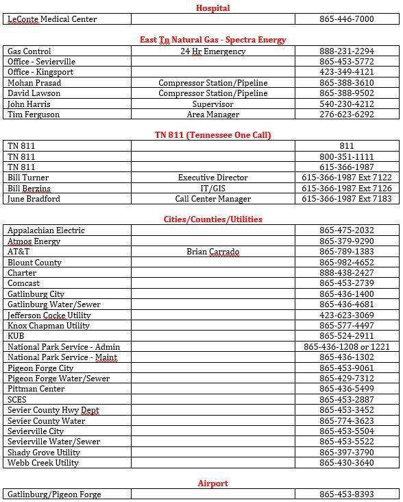
48 APPENDIX 1 CONTACTS Office Annette Ponds TENNESSEE PUBLIC UTILITY COMMISSION (TPUC) Phone Phone Fax Chief Phone Cell annette.ponds@tn.gov Gas Pipeline Safety Engineers Phone Cell Pete Hut pete.hut@tn.gov Shinisha Freeman shinisha.freeman@tn.gov Travis Aslinger travis.aslinger@tn.gov Phil Hendricks phil.hendricks@tn.gov Tim Thompson tim.thompson@tn.gov Regina Brown regina.a.brown2@tn.gov Administrative Assistant Phone Vicky Nelson vicky.nelson@tn.gov National Contact Phone Washington DC Response Center
49
50

51 APPENDIX 2 Forms
NATURAL GAS MAINTENANCE. Part 192 Subpart "M"
 NATURAL GAS MAINTENANCE Part 192 Subpart "M" CONTACT INFORMATION Pamela West Pipeline Safety Specialist U.S. Department of Transportation PHMSA Inspector Training and Qualifications Main: (405) 686-2310
New Hampshire Public Utilities Commission CFR 49 Part 192 Regulations. MINIMUM Pipeline Safety Regulations
 New Hampshire Public Utilities Commission CFR 49 Part 192 Regulations MINIMUM Pipeline Safety Regulations Application for Jurisdictional LPG Operators 1 Pipeline Safety Regulations 49 CFR Part 192 (NOTE:
BSR GPTC Z TR GM References and Reporting Page 1 of 8
 Page 1 of 8 PRIMARY: 192.605 SECONDARY: 191.23 PURPOSE: Review guide material added by TR 2009-17 to 5.1(e) and consider restructuring the guide material under 192.605 as discussed further below. ORIGIN/RATIONALE
2017 LGA 191/192 & 195 Pipeline Safety Conference
 2017 LGA 191/192 & 195 Pipeline Safety Conference Presented by: Wallace Jones Director, Gas Pipeline Safety Division Alabama Public Service Commission Issues that GPS/PSC Staff are having with Pipeline
O&M MANUAL HIGHLIGHTS
 O&M MANUAL HIGHLIGHTS GENERAL PROVISIONS Each pipeline must be operated according to this SUBPART 192.603(a) RECORDS 192.603(b) Keep records necessary to administer the procedures of 192.605 RECORDS Life
EQUIPMENT AND MATERIALS
 SCUD Procedure # EMER004 Page 1 of 5 SCOPE AND PURPOSE This procedure is to provide performing outside leak investigations with the necessary procedures for prompt and effective response and to protect
Veriforce TG CCT 609OP. Training Guide
 Training Guide Directions: This training guide is to be used by a Veriforce Authorized Evaluator/Trainer and Trainee during on-thejob training (OJT) or prior to an evaluation as a resource. (S) Indicates
PIPELINE SAFETY. Darin Burk, Manager Pipeline Safety. January 28, 2014
 PIPELINE SAFETY Darin Burk, Manager Pipeline Safety January 28, 2014 Congressional Delegation of Authority Pipeline Safety Act of 1968 Congress Delegated Inspection and Enforcement Authority to the Secretary
Subpart E. Pressure Testing
 Subpart E Pressure Testing 195.300 Scope This subpart prescribes minimum requirements for pressure testing of steel pipelines. However, this subpart does not apply to movement of pipe covered by 195.424.
49 CFR 195 Regulatory Overview
 49 CFR 195 Regulatory Overview Overview DOT PHMSA OPS Relates to public safety, governs materials, design, construction, operations and maintenance Applies to either transmission, distribution or jurisdictional
NATURAL GAS DISTRIBUTION SYSTEM MAYOR: ROBERT BOB HARDY OPERATOR: MICHAEL WARREN
 CITY OF WESTLAKE FOR NATURAL GAS DISTRIBUTION SYSTEM MAYOR: ROBERT BOB HARDY OPERATOR: MICHAEL WARREN Prepared by: Pipeline Integrity Partners, LLC January 2019 TABLE OF CONTENTS Emergency Plans (192.615)...
SECTION PRESSURE TESTING OF PIPING
 SECTION 15044 PRESSURE TESTING OF PIPING PART 1 - GENERAL 1.01 DESCRIPTION A. Scope of Work: This section specifies the leakage and pressure testing of piping. B. Testing Records: PART 2 - PRODUCTS 2.01
EMERGENCY OPERATIONS MANUAL
 EMERGENCY OPERATIONS MANUAL SEVIER COUNTY UTILITY DISTRICT EMERGENCY MANUAL ANNUAL REVIEW SHEET YEAR 2016 2017 2018 2019 2020 2021 2022 2023 2024 2025 2026 2027 2028 2029 2030 2031 2032 ADMINISTRATORS
OPERATING PROCEDURES
 OPERATING PROCEDURES 1.0 Purpose This element identifies Petsec s Operating Procedures for its Safety and Environmental Management System (SEMS) Program; it applies to all Petsec operations. Petsec is
HYDROSTATIC LEAK TEST PROCEDURE
 This information is proprietary and shall not be disclosed outside your organization, nor shall it be duplicated, used or disclosed for purposes other than as permitted under the agreement with Kinetics
Leticia Santos Hernández Pipeline Safety Specialist U.S. Department of Transportation PHMSA Inspector Training and Qualifications
 Leticia Santos Hernández Pipeline Safety Specialist U.S. Department of Transportation PHMSA Inspector Training and Qualifications Email: leticia.santos@dot.gov Office: 405-686-2310 192.605(b) Gas Reports
1.0 Scope and Application. 2.0 Definitions. Cal Poly Risk Management Confined Space Program Page 1
 Page 1 1.0 Scope and Application The following procedures describe safe operating practices in confined spaces. These may be sewers, pipelines, tanks, boiler compartments, ducts, vaults, pits, vats, bins
ONSHORE GAS GATHERING FAQS
 ONSHORE GAS GATHERING FAQS These Frequently Asked Questions (FAQs) are intended to clarify, explain, and promote better understanding of the gas gathering line rules. These FAQs are not substantive rules
ANNEX AMENDMENTS TO THE INTERNATIONAL CODE FOR FIRE SAFETY SYSTEMS (FSS CODE) CHAPTER 15 INERT GAS SYSTEMS
 CHAPTER 15 INERT GAS SYSTEMS") Annex 3, page 2 ANNEX AMENDMENTS TO THE INTERNATIONAL CODE FOR FIRE SAFETY SYSTEMS (FSS CODE) CHAPTER 15 INERT GAS SYSTEMS The text of existing chapter 15 is replaced by the following: "1 Application This
Annex 3, page 2 ANNEX AMENDMENTS TO THE INTERNATIONAL CODE FOR FIRE SAFETY SYSTEMS (FSS CODE) CHAPTER 15 INERT GAS SYSTEMS The text of existing chapter 15 is replaced by the following: "1 Application This
Part 192 Subparts J & K. Testing & Uprating
 Part 192 Subparts J & K Testing & Uprating MAOP, Testing, & Uprating Are All Linked MAOP = Maximum Pressure Allowed By Regulations (192.619 et seq.) MAOP Determined By Operator for Each Pipeline or Segment
TABLE OF CONTENTS PART 2 - CONFINED SPACES
 May 11, 2006 TABLE OF CONTENTS PART 2 - CONFINED SPACES Page DEFINITIONS... 2-1 GENERAL... 2-2 RESPONSIBILITIES... 2-2 HAZARD ASSESSMENT AND WORK PROCEDURES... 2-3 IDENTIFICATION AND ENTRY PERMITS... 2-3
APPENDIX A GLOSSARY AND ACRONYMS
 APPENDIX A GLOSSARY AND ACRONYMS GLOSSARY To understand this manual, operators of small natural gas systems need to know the meaning of some commonly used terms. The terms are defined below for the purpose
FLAMMABLE GASES AND FLAMMABLE CRYOGENIC FLUIDS
 CHAPTER 35 FLAMMABLE GASES AND FLAMMABLE CRYOGENIC FLUIDS SECTION 3501 GENERAL 3501.1 Scope. The storage and use of flammable gases shall be in accordance with this chapter. Compressed gases shall also
HEALTH AND SAFETY PROGRAM 201 HOT TAP PERMIT/FILLET WELD REPAIRS
 Page 1 of 15 1.0 PURPOSE 1.1. Axiall, Plaquemine Complex, has developed this Hot Tap Permit Program to eliminate potential accidents, injuries, and to enhance employee protection. 1.2. To provide for the
Un-Pressurized Orefice Fittings FIO EZ. Parts List and Operation Instructions TECHNICAL MANUAL. Dn 2-6 Class Lbs
 Un-Pressurized Orefice Fittings FIO EZ Parts List and Operation Instructions TECHNICAL MANUAL Dn 2-6 Class 150-600 Lbs US US 2 FIO EZ - MT 108-US - 05-2016 FIO EZ Important Instructions US Pietro Fiorentini
Covered Task 409OP Training Guide Inspecting Interference Bonds
 Directions This training guide is to be used by a Subject matter expert (SME) authorized Evaluator/Trainer and Trainee during on-thejob training (OJT) or prior to an evaluation as a resource. (S) Indicates
Operation and Maintenance Plan. Master Meter Gas Distribution Systems
 Operation and Maintenance Plan For Master Meter Gas Distribution Systems MASTER METER SYSTEM A natural gas pipeline system for distributing natural gas for resale within, but not limited to, a distinct
Key Technology, Inc. Confined Space Entry Program. July, 2017
 Key Technology, Inc. Confined Space Entry Program July, 2017 Page 1 of 11 Key Technology, Inc. CONFINED SPACE ENTRY PROGRAM OVERVIEW Purpose: The purpose of this program is to ensure the protection of
Committee Input No. 59-NFPA [ Section No. 5.9 ]
![Committee Input No. 59-NFPA [ Section No. 5.9 ]](/thumbs/77/75129979.jpg "Committee Input No. 59-NFPA [ Section No. 5.9 ]") Committee Input No. 59-NFPA 54-2012 [ Section No. 5.9 ] 5.9 Overpressure Protection Devices. 5.9.1 General 1 Where required. Overpressure Where the serving gas supplier delivers gas at a pressure greater
Committee Input No. 59-NFPA 54-2012 [ Section No. 5.9 ] 5.9 Overpressure Protection Devices. 5.9.1 General 1 Where required. Overpressure Where the serving gas supplier delivers gas at a pressure greater
CONFINED SPACE WRITTEN PROGRAM
 CONFINED SPACE WRITTEN PROGRAM Maple River Public Schools ISD#2135 Confined Space Entry Plan (Permit Required) Maple River Public School Plan last updated: October, 2014 Authority and Scope Regulation:
Striking an underground pipeline or underground electric line can lead to serious injury or death. If you hit either, call (800) , even if
 , even if") 1 Striking an underground pipeline or underground electric line can lead to serious injury or death. If you hit either, call (800) 477-5050, even if there is no apparent damage. Call 911 if gas is blowing
1 Striking an underground pipeline or underground electric line can lead to serious injury or death. If you hit either, call (800) 477-5050, even if there is no apparent damage. Call 911 if gas is blowing
SAFETY POLICY AND PROCEDURE MANUAL All Euramax Subsidiaries. Number K-3.0 Welding Safety Procedures
 Number K-3.0 Issued: 1/2009 Revised: 3/2016 Page 1 of 3 1.0 PURPOSE: To standardize procedures associated with production and maintenance welding and to minimize the potential risk of accident or injury
INOGATE Technical Secretariat UK Experience European Standards Implementation Key Expert Phil Winnard Session 2 Georgia, October 2015
 INOGATE Technical Secretariat UK Experience European Standards Implementation Key Expert Phil Winnard Session 2 Georgia, October 2015 BUILDING PARTNERSHIPS FOR ENERGY SECURITY www.inogate.org EN 12186
CLEANING, INSPECTION, AND TESTING OF SEWERS
 CLEANING, INSPECTION, AND TESTING OF SEWERS PART 1 - GENERAL 1.01 SECTION INCLUDES A. Cleaning, Inspecting, and Testing Sanitary Sewers B. Cleaning, Inspecting, and Testing Storm Sewers C. Cleaning and
DUQUESNE UNIVERSITY LOCKOUT/TAGOUT PROGRAM
 DUQUESNE UNIVERSITY LOCKOUT/TAGOUT PROGRAM Prepared by: Environmental Health and Safety Department TABLE OF CONTENTS Page Purpose 1 Scope 1 Introduction 2 Regulatory Requirements 2 Protective Materials
American Society of Sanitary Engineering PRODUCT (SEAL) LISTING PROGRAM
 LISTING PROGRAM") American Society of Sanitary Engineering PRODUCT (SEAL) LISTING PROGRAM ASSE STANDARD #1048 - REVISED: 2009 Double Check Detector Fire Protection Backflow Prevention Assemblies Separate, complete laboratory
American Society of Sanitary Engineering PRODUCT (SEAL) LISTING PROGRAM ASSE STANDARD #1048 - REVISED: 2009 Double Check Detector Fire Protection Backflow Prevention Assemblies Separate, complete laboratory
Calibration Requirements for Direct Reading Confined Space Gas Detectors
 : Calibration Requirements for Direct Reading Confined Space Gas Detectors However, the definition of bump test has always been a little slippery. Some manufacturers differentiate between a bump test that
Investigation of failures
 49 CFR 192.617 192.617 Investigation of failures Each operator shall establish procedures for analyzing accidents and failures, including the selection of samples of the failed facility or equipment for
The purpose of this task is to prevent damage from occurring to the pipe or it s coating when backfilling an exposed pipeline.
 OQ Task Name Task 39.0 Backfill 1.0 Task Description This task applies to the process and material to backfill or cover a buried pipeline which has been excavated or otherwise exposed, Backfilling shall
CONFINED SPACE ENTRY PROGRAM
 CONFINED SPACE ENTRY PROGRAM 2003 ENVIRONMENTAL HEALTH AND SAFETY/RISK MANAGEMENT p1 Rev. 01/07/2003 wrk Environmental Health and Safety/Risk Management CSUCI Confined Space Entry Program TABLE OF CONTENTS
Scope: This plan applies to all personnel, including contractors, who enter or work in confined spaces, or supervise such activities.
 11/13/1995 4 5/20/2013 1 of 10 Authority and Scope Regulation: 29 CFR 1910.146 Scope: This plan applies to all personnel, including contractors, who enter or work in confined spaces, or supervise such
Piped Air SCBA Refilling System Standard
 WALT WHITE Fire Chief 5770 Freeport Blvd., Suite 200 Sacramento, CA 95822-3516 Ph: (916) 808-1300 Fax: (916) 808-1629 www.sacfire.org Piped Air SCBA Refilling System Standard SCOPE: This specification
INSTRUCTIONS FOR FORM RSPA F (1-2001) ACCIDENT REPORT - HAZARDOUS LIQUID PIPE SYSTEMS GENERAL INSTRUCTIONS
 ACCIDENT REPORT - HAZARDOUS LIQUID PIPE SYSTEMS GENERAL INSTRUCTIONS") INSTRUCTIONS FOR FORM RSPA F 7000-1 (1-2001) ACCIDENT REPORT - HAZARDOUS LIQUID PIPE SYSTEMS GENERAL INSTRUCTIONS Each hazardous liquid pipeline operator shall file Form RSPA F 7000-1 for an accident that
INSTRUCTIONS FOR FORM RSPA F 7000-1 (1-2001) ACCIDENT REPORT - HAZARDOUS LIQUID PIPE SYSTEMS GENERAL INSTRUCTIONS Each hazardous liquid pipeline operator shall file Form RSPA F 7000-1 for an accident that
UTAS EH&S INSTRUCTION No. 036 June 2012 Revision No. 3. Purging of Flammable Gas Equipment and/or Piping (Explosion Hazard)
") Purging of Flammable Gas Equipment and/or Piping (Explosion Hazard) APPLICABILITY: This EH&S Instruction applies to UTAS sites worldwide, including contractors working at UTAS facilities. The document
Purging of Flammable Gas Equipment and/or Piping (Explosion Hazard) APPLICABILITY: This EH&S Instruction applies to UTAS sites worldwide, including contractors working at UTAS facilities. The document
Confined Space Policy
 Confined Space Policy Introduction Employees of Lawrence University may at times be required to enter into and perform work inside tanks, chests, sewers, vessels and other confined spaces. Due to the potentially
Confined Space Entry Safety Program
 Confined Space Entry Safety Program Table of Contents SCOPE...2 DEFINITIONS..2 PROGRAM ELEMENTS...3 SPACE EVALUATION...4 IDENTIFICATION AND CLASSIFICATION...4 POSTING...4 RECLASSIFICATION OF PERMIT SPACE...4
Confined Space Program
 Insert City Name Page 1 of 6 Purpose Regularly, confined spaces must be entered for inspection, cleaning or repair. Such spaces can present unusual hazards such as lack of sufficient oxygen, special mechanical
Confined Space Entry Program 8 CCR 5157
 TABLE OF CONTENTS 1. POLICY... 2 2. PURPOSE... 2 3. SCOPE... 2 4. DEFINITIONS... 2 5. CONFINED SPACES IN THE SACRAMENTO STATE... 4 6. PERMIT SPACE ENTRY - PERSONNEL RESPONSIBILITIES... 4 6.1. CONFINED
Residential and Small Commercial
 Page 1 of 7 Companies Affected: NIPSCO CGV CMD CKY COH CMA CPA REFERENCE 49 CFR Part 192.353, 192.355, 192.357 1. GENERAL The purpose of this standard is to provide requirements for the inspection or installation
Process Safety Management Of Highly Hazardous Chemicals OSHA 29 CFR
 Process Safety Management Of Highly Hazardous Chemicals OSHA 29 CFR 1910.119 PSM - Definition Not all refining hazards are caused by the same factors or involve ve the same degree of potential damage.
TEMPLE UNIVERSITY ENVIRONMENTAL HEALTH AND RADIATION SAFETY
 Page 1 of 9 ISSUED: 5/00 REVISED: 08/06 Introduction Purpose: In accordance with applicable regulations and Temple University, this policy was developed to minimize exposure to Ethylene Oxide. Applicability
LOCK-OUT/TAG-OUT (LO/TO) SAFETY PROGRAM
 SAFETY PROGRAM") LOCK-OUT/TAG-OUT (LO/TO) SAFETY PROGRAM REGULATORY STANDARD: OSHA - 29 CFR 1910.147 BASIS: Approximately three million workers in the United States face risks from uncontrolled energy when servicing machinery
LOCK-OUT/TAG-OUT (LO/TO) SAFETY PROGRAM REGULATORY STANDARD: OSHA - 29 CFR 1910.147 BASIS: Approximately three million workers in the United States face risks from uncontrolled energy when servicing machinery
This section applies to all open excavations made in the earth's surface. Excavations are defined to include trenches.
 Appendix H Specific Excavation Requirements This section applies to all open excavations made in the earth's surface. Excavations are defined to include trenches. Surface encumbrances All surface encumbrances
Tool Box Talk. Confined Space Entry New Construction Standard (2015)
") Confined Space Entry New Construction Standard (2015) What s all this about Confined Space Entry and how does it affect the construction industry? On May 4, 2015 the Occupation Safety and Health Administration
Confined Space Entry New Construction Standard (2015) What s all this about Confined Space Entry and how does it affect the construction industry? On May 4, 2015 the Occupation Safety and Health Administration
Subpart L NOTES: NOTES:
 Odorization of Gas Subpart L Wayne St. Germain Pipeline Safety Specialist Phone (405) 954 7219 Live Person (405) 954 8575 Direct Line Fax (405) 954 0206 Email wayne.stgermain@dot.gov Odorization of Gas
NB/NBR NITROGEN BOOSTER FOR AVIATION SERVICE
 NB/NBR NITROGEN BOOSTER FOR AVIATION SERVICE INSTALLATION, OPERATION & MAINTENANCE MANUAL INTERFACE DEVICES, INC. 230 Depot Road, Milford, CT 06460 Ph: (203) 878-4648, Fx: (203) 882-0885, E-mail: info@interfacedevices.com
1 Exam Prep. Tabs and Highlights
 1 Exam Prep NFPA 14: Standard for the Installation of Standpipe and Hose Systems Tabs and s These 1 Exam Prep tabs are based on the NFPA 14: Standard for the Installation of Standpipe and Hose Systems,
Status Date Prepared Reviewed Endorsed Approved
 Discipline Engineering Standard NSW Category Signalling Title Introduction to Signalling Maintenance Procedures Reference Number SMP 01 (RIC Standard: SC 00 52 00 01 SI) Document Control Status Date Prepared
Standard Pneumatic Test Procedure Requirements for Piping Systems
 the pressure equipment safety authority Standard Pneumatic Test Procedure Requirements for Piping Systems AB-522 Edition 2, Rev. 1 Issued 2016-10-24 Table of Contents FOREWORD... 1 1.0 INTRODUCTION...
Responding to Natural Gas Pipeline Emergencies
 Responding to Natural Gas Pipeline Emergencies Who is Florida Gas Transmission? Florida Gas Transmission operates nearly 5,000-miles of interstate natural gas transmission pipelines, a system that extends
Energy Control. Suite 2A, 55 Frid Street Hamilton, ON L8P 4M3 office: cell:
 Energy Control Suite 2A, 55 Frid Street Hamilton, ON L8P 4M3 office: 905.577.0303 cell: 905.977.0210 consultant@staffaid.ca www.staffaid.com Safety, Energy Control, Power Lockout & Function Test Procedures
ACCREDITATION OF ON-LINE LEAK SEAL ORGANIZATIONS
 ACCREDITATION OF ON-LINE LEAK SEAL ORGANIZATIONS TSSA GUIDE FOR SURVEY TEAMS The Technical Standards and Safety Authority Boilers and Pressure Vessels Safety Division 3300 Bloor Street West 14th Floor,
Covered Task 614OP Training Guide Purging Pipeline Facilities with Air or Inert Gas
 Directions This training guide is to be used by a Subject matter expert (SME) authorized Evaluator/Trainer and Trainee during on-thejob training (OJT) or prior to an evaluation as a resource. (S) Indicates
Hot Work Program. University of Wisconsin-Platteville Reviewed 4/2016
 Hot Work Program University of Wisconsin-Platteville Reviewed 4/2016 The purpose of the Hot Work Program is to establish safety procedures for employees, contractors, and subcontractors engaging in any
Flammability Chart. Gas Formula Ignition
 Leak Detection 101 Investigating a leak is simplified if you know the basics. By J. Scott Kleppe Sensit (J and N Enterprises, Inc.) Every day new gas services are added to provide economical energy to
TECHNICAL DATA. the Viking Pilot Pressure Regulating Valve 1 Model A-1 Speed Control Assembly: OBSOLETE. the Viking Speed Control Assembly 1
 November 30, 1994 534 a 1. PRODUCT NAME VIKING 2" (50mm), 3" (75mm), 4" (100mm), 6" (150mm) 2. MANUFACTURER THE VIKING CORPORATION 210 N. Industrial Park Road Hastings, Michigan 49058 U.S.A. Telephone:
CONFINED SPACE AWARENESS
 Document Number: HSE09-001 June 1, 2013 AWARENESS Author: A Holland MAPP Construction - Corporate 344 Third Street Baton Rouge, LA 70801 (225) 757-0111 MAPP Construction - Houston 1511 Katy Freeway, Suite
TECHNICAL DATA Q= C. Table 1 - Specifications
 September 25, 2013 Pressure Regulation 537a 1. Description The Model B-3 Pilot Operated Pressure Control Valve is a factory assembled unit. The unit consists of a Model J-2 Halar coated Flow Control Valve,
Instruction Bulletin Addendum For Pressure-Balanced In Situ Oxygen Probes
 Instruction Bulletin Addendum For Pressure-Balanced In Situ Oxygen Probes Instruction Bulletin Addendum IB PB1000 Part no. Serial no. Order no. Oxymitter 4000 Applicability: Used with pressure-balancing
CLASS DH - PNEUMATIC TESTING - GREATER THAN 1 BAR (15 PSIG)
") Page 1 of 10 CLASS DH - PNEUMATIC TESTING - GREATER THAN 1 BAR (15 PSIG) 1. SCOPE 1.1 To provide definitive requirements for HIGH PRESSURE PNEUMATIC testing of piping systems according to ASME B31.3. This
Page 1 of 10 CLASS DH - PNEUMATIC TESTING - GREATER THAN 1 BAR (15 PSIG) 1. SCOPE 1.1 To provide definitive requirements for HIGH PRESSURE PNEUMATIC testing of piping systems according to ASME B31.3. This
Lockout/Tagout Training Overview. Safety Fest 2013
 Lockout/Tagout Training Overview Safety Fest 2013 Purpose of Lockout/Tagout The standard covers the servicing and maintenance of machine and equipment in which the unexpected energization or start up of
IAPMO GUIDE CRITERIA FOR BALL VALVES IAPMO IGC PURPOSE
 INTERNATIONAL ASSOCIATION OF PLUMBING AND MECHANICAL OFFICIALS IAPMO GUIDE CRITERIA FOR BALL VALVES IAPMO IGC 157-20067 1 PURPOSE 1.1 The purpose of this standard is to establish an acceptable standard
CONTACT INFORMATION. Wayne St. Germain Transportation Specialist U.S. Department of Transportation PHMSA Inspector Training and Qualifications
 ODORIZATION ISSUES CONTACT INFORMATION Wayne St. Germain Transportation Specialist U.S. Department of Transportation PHMSA Inspector Training and Qualifications Email: wayne.stgermain@dot.gov GAS REPORTS
Health & Safety Policy and Procedures Manual SECTION 6 ELECTRICAL SAFETY / CONTROL OF HAZARDOUS ENERGY
 SECTION 6 ELECTRICAL SAFETY / CONTROL OF HAZARDOUS ENERGY 1. CONTROL OF HAZARDOUS ENERGY POLICY AND PROCEDURES A. OSHA References: 29 CFR 1910.147, 29 CFR 1910.332, 29 CFR 1910.333, 29 CFR 1926.417 B.
Gettysburg College. Energy Control Program
 Gettysburg College Energy Control Program Adopted October 2009 Reviewed and Updated February 2015 Reviewed and Updated July 2015 I. Energy Control Procedures Table of Contents A. General Lockout Procedures
Sterile Visual Flow Indicator
 Sterile Visual Flow Indicator Sanitary Process Connection Installation / Operation / Maintenance Manual P.O. Box 1116 Twinsburg, OH 44087 Phone: 330/405-3040 Fax: 330/405-3070 E-mail: view@ljstar.com Web
SAFETY DIRECTIVE 2.0 DEPARTMENTS AFFECTED. This Administrative Directive shall apply to all Town of Marana departments and employees.
 SAFETY DIRECTIVE Title: Control of Hazardous Energy Lock-out/Tag-out/Try-out Issuing Department: Town Manager s Safety Office Effective Date: July 1, 2014 Approved: Gilbert Davidson, Town Manager Type
Types 749B and R130 Changeover Manifolds
 Instruction Manual MCK-1179 Types 749B and R130 June 2012 Types 749B and R130 Changeover Manifolds TYPE HSRL-749B TYPE 64SR/122 TYPE R130/21 TYPE 749B/21 Figure 1. Changeover Manifolds and Regulator Assemblies
Installation, Operating and Maintenance Instructions. V914 Cast Iron Flanged Swing Check Valve V914
 Installation, Operating and Maintenance Instructions V914 Cast Iron Flanged Swing Check Valve V914 THE PRESSURE EQUIPMENT DIRECTIVE 97/23/EC and CE MARKING The Pressure Equipment Regulations 1999 (SI 1999/2001)
623 Series Dome Load Regulators
 ADI 3202C Certified ISO 9001 623 Series Dome Load Regulators INSTALLATION AND OPERATION INSTRUCTIONS This Equipment is intended to be installed and operated by trained personnel. Before Installing or Operating,
Excavations and Trenches
 Purpose Excavation and trenching are among the most hazardous work activities undertaken by the TNRD. This document outlines general requirements and specific safe work procedures to ensure the health
To ensure compliance to WorkSafeBC Regulation Part 9 Confined Space Entry which states:
 Manufacturing SS No. 4 Safety Standard Confined Space Purpose: These procedures were developed to protect employees from the serious hazards associated with.entering and working within confined spaces.
Secondary Aluminum NESHAP 40 CFR Part 63 Subpart RRR. Example Malfunction Plan for Plant ABC
 Secondary Aluminum NESHAP 40 CFR Part 63 Subpart RRR Example Malfunction Plan for Plant ABC Final April 3, 2003 This is an example of one way to write a malfunction plan. Citations to Federal requirements
KENNEDY VALVE OPERATION & MAINTENANCE MANUAL
 2 54 ROTATING DISC GATE VALVE OPERATION & MAINTENANCE MANUAL Rel. 5/27/16 1 TABLE OF CONTENTS 3 General 3 Receipt & Inspection 4 Gate Valve Storage & Handling 5 6 Installation 7 Operation 8 Field Testing
HAZARDOUS WASTE OPERATIONS AND EMERGENCY RESPONSE
 Page 1 of 10 HAZARDOUS WASTE OPERATIONS AND EMERGENCY RESPONSE 1.0 SCOPE This Performance Assessment Guide for Hazardous Waste Operations and Emergency Response (HAZWOPER) will be used to carry out the
Pressures MAOP MOP OP
 MAOP Pressures MAOP MOP OP MAOP "Maximum Allowable Operating Pressure" means the maximum pressure at which a pipeline or segment of a pipeline may be operated under this part. 192.3 MOP "Maximum Actual
CLASS D - SENSITIVE LEAK TEST GAS AND BUBBLE METHOD. 1.1 To provide definitive requirements for PNEUMATIC pressure testing of piping systems.
 Page 1 of 7 CLASS D - SENSITIVE LEAK TEST GAS AND BUBBLE METHOD 1. SCOPE 1.1 To provide definitive requirements for PNEUMATIC pressure testing of piping systems. 1.2 The piping system as used herein is
Be our partner in safe, reliable natural gas delivery
 Wide Web at. pipeline operators. The industry has a proven record of safety. Por favor visite para Main, House Main Wide Web at. pipeline operators. The industry has a proven record of safety. Por favor
The Johns Hopkins University/The Johns Hopkins Hospital Health, Safety and Environment Manual Safety Policies:
 Page 1 of 6 Keywords: Airborne Combustible, Atmospheric Monitoring, Atmospheric Oxygen, Authorized Entrant, Body Harness, Combustible Gas Meter, Communication Procedure, Confined Space, CPR, Entry, Entry
ARKANSAS TECH UNIVERSITY FACILITIES MANAGEMENT HEALTH AND SAFETY MANUAL (LOCKOUT/TAGOUT) 30.0
 30.0") () 30.0 The purpose of the Energy Control Policy (Lockout/Tagout) is to ensure that before any employee performs any servicing and/or maintenance on machinery or equipment, where the unexpected energizing,
() 30.0 The purpose of the Energy Control Policy (Lockout/Tagout) is to ensure that before any employee performs any servicing and/or maintenance on machinery or equipment, where the unexpected energizing,
Safety. April 2018 Supersedes all previous publications 2018 Chevron Phillips Chemical Company LP
 Technical Note 802 Leak Testing of Polyethylene Pipe For Municipal and Industrial Applications Part 1 Pre-Test Considerations Leak testing may be used to find leaks in a newly constructed or newly modified
PROCEDURES FOR REPAIRS TO ASME NV STAMPED PRESSURE RELIEF DEVICES OF NUCLEAR SAFETY RELATED PRESSURE RELIEF VALVES
 NB16 0603 NR Task Group 1 9 16 1. One update by NR task group page 3: 7/17/19 2. Two updates to S6.1 and S6.3 on page 1: 7/19/17 SUPPLEMENT 6 PROCEDURES FOR REPAIRS TO ASME NV STAMPED PRESSURE RELIEF DEVICES
1.0 PURPOSE 2.0 SCOPE 3.0 DEFINITIONS. ANSI: American National Standards Institute. CCC: Chemical Control Centre
 Revision Date: 5/17/2016 Page: 1 of 13 Health & Safety has developed the emergency eyewash & safety shower equipment procedure which will be implemented in 3 phases over the next four years. Phase 1 will
Hazardous Energy Control (Lockout-Tagout)
") Hazardous Energy Control (Lockout-Tagout) The purpose of this program is to prevent inadvertent operation or energization of machines, equipment, or processes in order to protect employees and establish
Hazardous Energy Control (Lockout-Tagout) The purpose of this program is to prevent inadvertent operation or energization of machines, equipment, or processes in order to protect employees and establish
PRESSURE RETEST. 49 CFR, (g) Co#: Vin#: DOT Spec: MAWP:
 Co#: Vin#: DOT Spec: MAWP:") PRESSURE RETEST 49 CFR, 180.407(g) Co#: Vin#: Spec: MAWP: Retest Date: Location: *External Inspection Performed: *Internal Inspection Performed: Test Pressure: psig Held for: min. (Must be at least 10
PRESSURE RETEST 49 CFR, 180.407(g) Co#: Vin#: Spec: MAWP: Retest Date: Location: *External Inspection Performed: *Internal Inspection Performed: Test Pressure: psig Held for: min. (Must be at least 10
High Pressure Inlet Kits for CONCOA BlendMites and BlendMasters
 ADI 3210-A ADI 3210-A Certified ISO 9001 Certified ISO 9001 High Pressure Inlet Kits for CONCOA BlendMites and BlendMasters Warning: An appropriately sized pressure relief device downstream of the regulator
U.S. CONCRETE, INC. SAFETY POLICY and PROCEDURE MANUAL
 SAFE -14 Page 1 of 8 U.S. CONCRETE, INC. SAFETY POLICY and PROCEDURE MANUAL FUNCTION Safety TOPIC Hotwork Permit Program OBJECTIVE(S): GENERAL POLICY: To provide a work atmosphere that is conducive to
API MPMS Chapter 17.6 Guidelines for Determining the Fullness of Pipelines between Vessels and Shore Tanks
 API MPMS Chapter 17.6 Guidelines for Determining the Fullness of Pipelines between Vessels and Shore Tanks 1. Scope This document describes procedures for determining or confirming the fill condition of
Confined Space Program
 Type: POLICY Revision: 01 Owner: BRL Document Name: HSPOL 011 Status: Current Nov 2014 Review Date: September 2017 Effective Date: 01 January 2015 Total Pages: 6 Definitions: New Old Confined space means
Safety Tips from the WorkSafe People. Building a Safety Program for Your Organization
 Building a Safety Program for Your Organization 1 Content Criteria and Examples of Confined Spaces Permit-Required Confined Space Non-Permit-Required Confined Space Employer Requirements Employee Requirements