GasClam Instrument User Manual V1.5
|
|
|
- Rolf Newman
- 5 years ago
- Views:
Transcription

1 GasClam Instrument User Manual V1.5
2 Page 1 of 37
3 Contents Declaration of Conformity Introduction to GasClam Effect of Water Keeping GasClam Dry and Clean Effects of Flooding Getting Started Packaging List Turning on the GasClam Physical Charateristics How GasClam Works and Access Areas Software Installation Running Installation Battery Change Software Connecting Main Screen Last Reading Stored Errors Switching Off The Unit Set Up Sampling Rate Sampling Count Device ID Venting Water Height Unit Date and Time Write Setting to GasClam Erasing Data Memory Returning to Main Screen Downloading Viewing Data Selecting File for Display Data Display Options Sampling Data Selecting Data Channel Displayed Multiple Parameters Importing Data to an Excel Spreadsheet Infrograph Start-Stop Data Calibration Data Error Messages Eeprom Bump Test Other Test Installation Service and Calibration Unit Calibration Service User Serviceable Parts Spare Parts Technical Specification Update Log Page 2 of 37
4 Declaration of Conformity The manufacturer, Elok-Opava, hereby declares and confirms that the characteristics of the product conform to the technical requirements stipulated by the technical standards. Furthermore, the manufacturer declares the product to be safe whilst adhering to the correct conditions for its installation, maintenance and use. Manufacturer: Elok-Opava s r.o., Sàdek 17, Velké Heraltice, Czech Republic Product Description: A landfill Gas monitor designed for in-situ borehole monitoring. The entire casing is made from solid stainless steel. The battery pack is in the upper part of the housing in a flame-proof casing. The measuring unit consisting of four gas sensors is located in the intrinsically safe lower part of the housing. The valves, pump and filter assembly are located at the bottom of the housing. Authorised Subject: FTZÚ, AO 210, NB 1026, Pikartská 7, OSTRAVA-RADVANICE, IČO Type of Protection: II 2G Ex d ib [ib] IIB T4 Certificate Number: Quality assurance notification: FTZÚ 02 ATEX Q 025 according to EN 13980, CE 1026 FTZÚ 07 ATEX 0105X Method of Determining Conformity: The product s conformity with the respective requirements of directive 94/9/EC - it was compared with the submitted documentation - it was tested according standards List of Technical Regulations and Standards: , NKO PTTI EN :2006 PTTI EN :2004 PTTI EN :2007 Directive 2004/108EC Electrical Apparatus for Potentially Explosive Atmospheres General Requirement Electrical Apparatus for Explosive Gas Atmospheres. Flameproof enclosures d Explosive Atmospheres Equipment Protection by Intrinsic Safety I EN :2006 Electrical Equipment for Measurement Name: Ing. Jiri Klein Position: Managing Director Signature: Date: 03/06/2008 Page 3 of 37
5 Introduction to GasClam GasClam is the world s first in-situ borehole gas monitor, suitable for the detection of a wide range of gasses commonly found in borehole monitoring, including Methane (CH 4 ), Carbon Dioxide (CO 2 ) and Oxygen (O 2 ). In addition to this the GasClam monitors temperature, barometric pressure and borehole pressure. All of these readings can be taken at programmable intervals, providing an invaluable set of data to the user. The default setting for the Gasclam is to take readings every hour, giving it approximately one months operational life. Data is downloaded either using a computer or via an optional modem and can be viewed within the GasClam software or exported for analysis in Excel. Whilst connected to the software the settings of the GasClam unit can be altered, including the frequency at which samples are taken and selecting venting options. In addition to the sensors already mentioned, the GasClam can be upgraded with a Photo ionisation Detector (PID) for detection of Volatile Organic Compounds (VOC s), a Carbon Monoxide (CO) sensor, Hydrogen Sulphide (H 2 S) sensor and a water depth sensor should the data be required. recommends that regular customer bump tests take place in conjunction with an annual service and calibration, which is performed by the Ion Science service department or an Ion Science approved service centre. Before using the GasClam you must read this manual paying particular attention to the section on the effects of water on your GasClam. Note: Before removing the GasClam from the field it must be run once in atmosphere to purge any hazardous gasses. Page 4 of 37


6 The effects of water on your GasClam GasClam is designed to overcome as far as possible the requirement to: measure gas concentrations, measure borehole and atmospheric pressure, allow a venting pathway between the borehole and atmosphere. To measure gas concentrations the gas must be dry and measurements of atmospheric pressure should not include the pressure of overlying water. As the GasClam can be in a position liable to flooding from above (flooded headworks) and below (high borehole water level) your help is required to optimise the performance of your GasClam by: carrying out simple preventive and remedial maintenance being aware of the limitations of data gathered under flood conditions. 1. Keeping your GasClam dry and clean in regular use To dry the gas before measurement there is a moisture stripping filter in the bottom section of the GasClam. Over time this will hydrate and its ability to remove moisture will decrease. If moisture is not successfully removed, concentration readings will be affected. If the moisture stripping filter is completely saturated it can dissolve, and it will then be pumped in to other sections of the GasClam resulting in catastrophic failure. This will always be avoided if the GasClam is installed vertically and the filter is replaced after every 800 samples. However, it is recommended to renew the filter whenever a visit is made to the GasClam to ensure optimal performance during data collection (see service and calibration section). To prevent water reaching the vent pathway the snorkel should always be attached to the vent hose barb. The top of this should be supported so it is located at the top of the headworks to reduce the chance of water ingress. In situations where the headworks is likely to be flooded the hose barb must be replaced by the vent blank. The supplied box spanner can be used to remove the hose barb and the supplied vent Alan key used to replace with the vent blank and washer. A B The GasClam should always have the snorkel attached to the vent hose barb (a). In situations where the headworks is likely to flood the hose barb must be replaced by the vent blank and washer (b). Page 5 of 37
7 The effects of water on your GasClam 2. Effects of flooding on data and GasClam When the unit is not sampling it has an ingress protection rating of IP-68 (submersible to 10 meters for 1 week). However, Immersion will effect data and May require subsequent corrective action These effects and requirements will differ whether immersed from above, i.e. flooded headworks, or from below, i.e. rise in borehole water level, see table below: Flooded Headworks Effects on data Effects on GasClam should vent breather be submerged: atmospheric pressure reading will be incorrect and will remain incorrect Scheduled venting will be ineffective. If submerged for an extended period the vent pipe may become flooded. The vent breather may become clogged by dirty water. Remedial action Use borehole pressure as approximate replacement or use data from another source. When GasClam is visited Check data and call service centre if atmospheric pressure looks strange and they will advise Preventive maintenance If chamber is known to flood, or is already full of water Chose another chamber Or replace snorkel with bolt If chamber is liable to flooding replace vent breather each visit Flooded Borehole Effects on data Effects on GasClam Should water reach the bottom of the GasClam the inflow and outflow valves will remain closed and no samples will be taken: borehole pressure reading will be incorrect gas concentration readings will be incorrect None Remedial action Data points collected whilst the sampling cycle was disabled will be marked None Preventive maintenance If borehole water level is known to be high or is already full of water Chose another chamber Or extend the borehole above ground level Page 6 of 37
 3 Box spanner for removing barbs 1 Blank (NOT Fitted) + washer 1 Length of pipe (30cm) 3 Battery Allen Key 1 Vent blank Allen Key 1 Communication cable 1 Start")
8 Getting Started Packing list Please take a little time to examine the contents of the GasClam package. Item Description Qty Barbs (Fitted) 3 Box spanner for removing barbs 1 Blank (NOT Fitted) + washer 1 Length of pipe (30cm) 3 Battery Allen Key 1 Vent blank Allen Key 1 Communication cable 1 Start cable 1 Manual and software (on CD) 1 Rubber Collar 1 GasClam Unit 1 1.5v Duracell Batteries (Fitted) 2 Moisture Stripping Filter 1 Accessory Kit 1 Moisture stripping filter 6 Snorkel (complete) 1 Snorkel filter 2 O-ring (part 22) 5 O-ring (part 21) 5 Turning on the GasClam The GasClam can be switched on and off using the remote. The remote connects to the communication port on top of the GasClam. To start the GasClam hold the button down for two seconds, the red LED will flash rapidly indicating the GasClam has started and is currently going through the processes in a sampling cycle, this equates to sampling mode. After the sampling processes have finished the red LED flashes intermittently, this equates to the measuring mode. To stop the GasClam press the button for two seconds, when it has stopped the LED will stop flashing, this equates to sleeping mode No flashing Rapid flash Intermittent flash Sleeping Sampling Measuring Page 7 of 37


 10.")
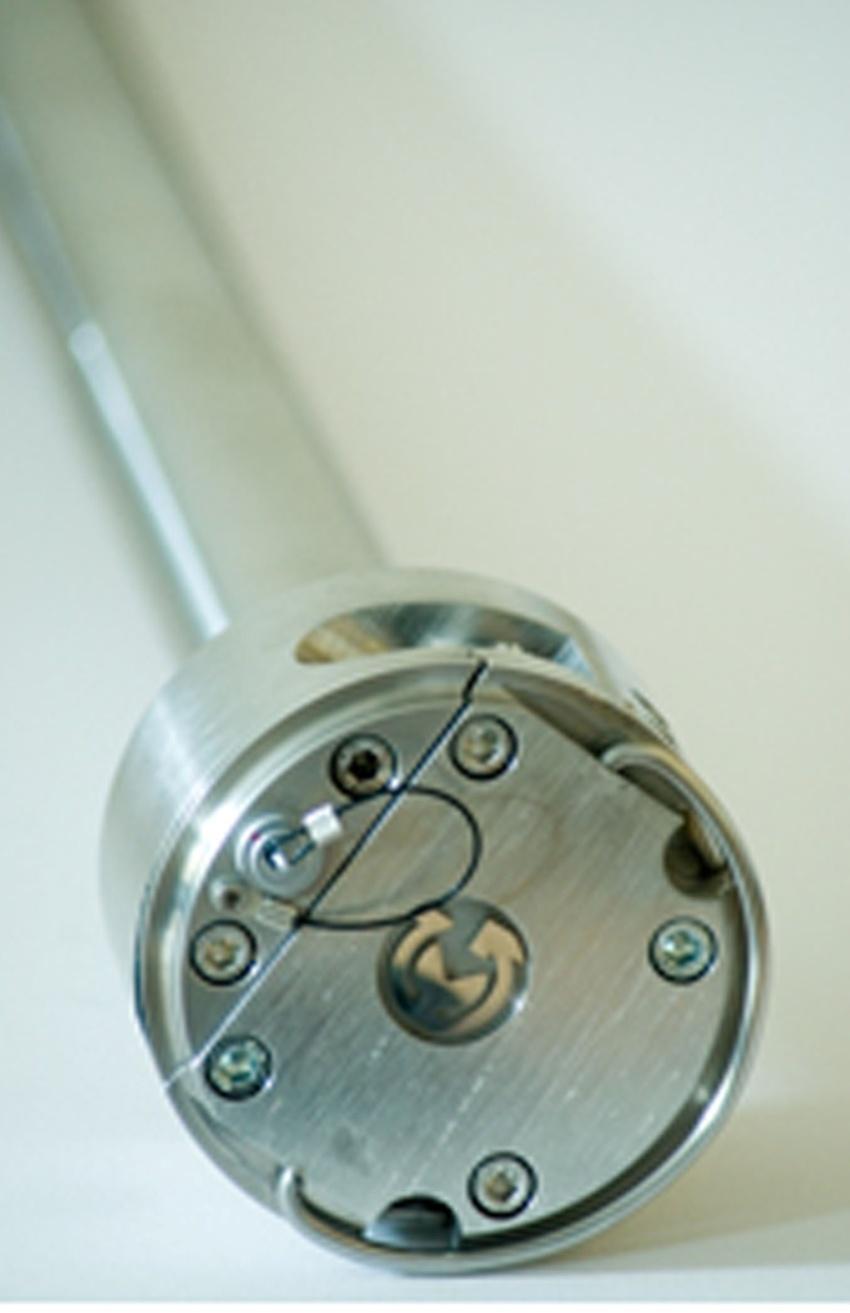
9 Getting Started Physical Characteristics Communication port 2. Pressure transducer port 3. Pressure transducer port cap 4. Gas inlet 5. Gas Outlet 6. Water proximity sensor 7. Pressure transducer hook 8. Battery compartment lid 9. Vent (with hose barb) 10. Rubber Collar GasClam identification plates with intrinsic safety specifications. Page 8 of 37

10 Getting Started How the GasClam Works and access areas Page 9 of 37
11 Getting Started Software Installation System Requirements The GasClam software needs 30MB free space on the hard disk for installation. The programme will run on the following platforms: - Windows 98 - Windows 98 Second Edition - Windows 2000 service pack 3 - Windows ME - Windows Server Windows XP service pack 2 - Windows Vista - Windows 7 The programme needs.net Framework 2.0 (x86) installed to run properly. This version is included on the software CD, alternatively it can be downloaded from the Microsoft website. Running the installation software Insert the installation CD or USB stick and copy the software folder on to the PC. There are two installation options. 1) If you have an old version of DotNetFX, 2.0 (x86) then double click the setup icon to update the DotNetFX. (If you already have this version and you try to upgrade an error will occur, ignore this and go to the next option) 2) If you already have this version of DotNetFX then double left click the GasClamUnit icon. The guide will then take you through the installation process step by step. The default location for the GasClam software is: C:\Program Files\Salamander\GasClam Page 10 of 37


12 Getting Started Battery Change Warning: For reasons of intrinsic safety, batteries MUST NOT be changed within potentially flammable areas. Always ensure you are in a safe area before carrying out any type of maintenance on your GasClam Battery types that can be used: For Intrinsic Safety and reduced risk of explosion you must only use Duracell 1.5 V LR20 Alkaline-Manganese MN1300 batteries or a 2 x 1,2V LR20 Nickel-metal hydride Saft VH D 9500 rechargeable pack. Do not mix old and new batteries within the same unit, change both batteries at the same time. Failure to do so will reduce battery life of the new cell fitted. The battery compartment is accessed by removing the 4 screws from the battery compartment lid, see diagram. To remove the batteries tilt the GasClam until they fall out. Replace with the stipulated batteries positive terminal facing down. Take care when replacing the cover to ensure the O-ring is not damaged by following the instructions below: The integrity of this O-ring should be checked every time the batteries are replaced. This needs to be replaced if any damage is noticed. Push the battery compartment lid down square on the GasClam When the O-ring is resting on the battery compartment push the lid down evenly on both sides to ensure it travels down square. This will prevent damage to the O-ring. When the O-ring is sitting in the compartment loosely tighten the screws. When tightening the cover alternate between screws to ensure the cover sits on the GasClam squarely. If this is not done the O- ring may be damaged. Page 11 of 37

 with the device ID displayed in box 1.")
13 Software Connecting The GasClam is connected to a computer using the supplied cable via the communication port on top of the GasClam and a serial port. If the computer does not have a serial port use a standard USB/Serial converter. You can either connect the unit before or after starting the software. If the software is opened before the GasClam is attached the screen appears as below. In this mode the options available are to view data (see later) or to close the application. After the GasClam is connected the screen will update (similar to below) with the device ID displayed in box 1. GasClam ID The window is divided in to 3 sections, navigation tabs (view data, download, setup and user calibration, bump test, other tests), Online Status and Last Reading Stored. Page 12 of 37
14 Software Main Screen Battery status displays battery voltage alongside a power bar, the bar changes colour according to capacity providing a rough guide to battery life*. Green: capacity is fine for a long sampling period Orange: Batteries need to be replaced very soon Red: Replace batteries immediately. *The voltage in the battery will decrease when the GasClam is sampling due to a load on the batteries, this is the voltage that should be used to assess battery condition (This is also the voltage that is logged). Note. If the battery capacity is no longer sufficient for the running of the unit during a programme the unit automatically interrupts the cycle and switches to sleeping mode, this will be logged as a battery error. The data is stored in the flash memory therefore the data will remain in the GasClam even if the batteries are completely flat. Samples left displays the remaining number of samples that can be stored in the memory. Samples taken/count When the GasClam is in sleeping mode this reads samples taken indicating how many sampling points are stored on the memory. When the GasClam is in sampling mode it reads Sample count and displays the number of finished cycles and the total number of cycles in the programme. For example, 254/4500 means that 254 cycles from 4500 required cycles have finished. Sampling every - shows the period between sampling. For example, value 1 hour. means that sampling frequency is 1 hour. Finish on displays the date and time that the sampling programme will finish. Serial number displays the serial number of the unit COM port displays which port the unit is connected to. Status displays the mode of the unit: When the unit is running a programme the following modes are possible: Sampling the GasClam is actively making a measurement. Measuring the GasClam is between sampling periods. When the GasClam is not running a programme the following modes are possible: Sleeping the unit is not running a programme. In this mode data can be downloaded and the unit programmed. Clear flash the unit is erasing flash memory data If the GasClam is not functioning correctly the status will read undefined status, if this occurs contact customer services immediately. Page 13 of 37
15 Software START/STOP Button this has several modes: The unit is in sleeping mode, to start the GasClam left click the button. The unit is actively sampling (it can be stopped by left clicking the button), after this has finished the button changes to: The unit is between samples and the programme can be stopped by left clicking the button. After starting the GasClam through the software wait until the first cycle is complete. The last readings stored will be updated and these values can be used to check that the GasClam is functioning correctly. Also this will remind the user that the GasClam has been started before leaving it for a period of unmanned data collection. Firmware shows the firmware version in the unit. Always use the software designated for the given firmware version. Last reading stored The last recorded values are displayed in the Last Reading Stored box. If the sampling cycle has started, these values will display measuring and are updated throughout the sampling process. The displayed ranges of individual sensors are as follows: Methane 0-100% Carbon Dioxide 0-100% Oxygen 0-25% Borehole Pressure mbar Barometric Pressure mbar Temperature - -5 C to +50 C Optional Water Level 0-25m Optional Dual CO/H2s sensor ppm/0-100ppm Optional VOC 1 PPM 0-4,000PPM Page 14 of 37

16 Software Errors If the GasClam is not functioning correctly an error message will be displayed at the top of the Software home screen, see below. Page 15 of 37
17 Software Different errors require different solutions, these are summarised below; Error Reason Solution Low Battery Battery voltage is below 1.8V for 10s GasClam will run but batteries need to be changed Flat Battery Filter Error Battery voltage is below 1.8V for 60s The moisture stripping filter is clogged The GasClam will not sample, batteries must be changed Change the moisture stripping filter. If this does not work then call the service centre Immersion Water in the borehole has risen to the base of the GasClam When water level drops the GasClam will start sampling again AD Overflow The AD convertor is not working. Check to see if it has happened only once or if it is a permanent error. If permanent reset the GasClam by removing and replacing batteries. If problem persists call the service centre. Flash Busy Full Memory Error SPI Flash Error Write The memory has timed out The memory is full The flash memory has not worked correctly Error writing to the flash memory Check to see if it has happened only once or if it is a permanent error. If permanent reset the GasClam by removing and replacing batteries. If problem persists call the service centre. Download GasClam and clear memory Check to see if it has happened only once or if it is a permanent error. If permanent reset the GasClam by removing and replacing batteries. If problem persists call the service centre. Check to see if it has happened only once or if it is a permanent error. If permanent reset the GasClam by removing and replacing batteries. If problem persists call the service centre. Pump Pump is not working correctly Call service centre. After the problem has been resolved clear the error message by clicking clr. To help trouble shoot errors the service centre will need the.gcl,.gce and.csv file (see page 23) Page 16 of 37


18 Software Switching off the unit If the unit is not going to be used for a long period it is recommended that it is turned off using the OFF button, this reduces the discharge from the batteries. When the off button is clicked a message will appear to ask if you really want to switch off. If the Yes button is clicked the following appears: The GasClam will turn off after the communication cable is disconnected, until then the main screen will appear as below: The GasClam will turn back on when the data cable is attached again. Page 17 of 37
, the longest 999 hours and 60 minutes.")
19 Software Setup The GasClam is programmed in the setup window and is accessed by left clicking the set up navigation tab, and the set up window then appears as below. Sampling Rate The sampling rate is defined in the Set Sample Rate box, the fastest sampling rate is 3 minutes (This is how long all the processes take), the longest 999 hours and 60 minutes.. Sample count The number of samples to be taken can either be set to the maximum possible by clicking the Always Maximum button or defined by the user in the Sample count box. The maximum figure displayed is (total memory space) minus the number of stored samples, the user defined value can be up to and including this. The estimated date and time of the end the programme is displayed under the text button. This information is calculated as follows: (Sample count * sample rate) + actual date and time. This is set to 800 as default to ensure the moisture stripping filter is not compromised. Device ID The user can specify the name of the GasClam in the Device ID box. This is useful if there is multiple GasClam on a site as the borehole number can be allocated to the GasClam. This information is used to create a filename when the data is downloaded. Page 18 of 37


 however, in order to calculate this distance 3 parameters need to be entered; water density, water sensor length and the distance")
20 Software Venting The GasClam has four venting modes, which can be selected in the Venting box (see below): Always Closed The vent is always closed Always Open The vent is always open. Open once per day - The vent opens once a day for a period of time defined by the user. The vent opens open immediately after the first sample and shuts after the allocated time. Open after every The vent opens and stays open for user defined periods. If the GasClam is to be located in a wet area and the vent blank is installed tick the vent plug inserted box. Water height The GasClam can measure the water level in the borehole using an optional pressure transducer. To enable the water level pressure transducer the water level enabled box in the Distance water height area needs to be ticked. The GasClam reports the level in meters below ground level (mbgl) however, in order to calculate this distance 3 parameters need to be entered; water density, water sensor length and the distance of the GasClam to the surface, see diagram below. Pure water has a density of 1000 kg/m3 at 4 C. Borehole pressure affects the water level reading but this is automatically corrected. Page 19 of 37

21 Software Unit date and time The time and date of the unit and computer are displayed in the Date and Time box, and are synchronised by left clicking the Set Time tab. The date and time is not stored when the unit is switched off or when the batteries run out or changed. Note. The time on the unit is likely to differ from the computers if the device was programmed on a different computer to the one it now is connected to. Write Settings to GasClam To activate a change in the setup up menu the write settings to GasClam button must be clicked. If this is successful a message saying Settings written successfully appear. Click OK to continue. Erasing Data Memory To erase all the data from the flash memory left click the Erase memory button. The status will change to Clear Flash during this process, when this is finished the status will change to Sleeping Warning This process erases stored data permanently. Make sure you have downloaded the data from the GasClam onto your computer. Return to main screen To return to the GasClam software s main window use the back button. Page 20 of 37

22 Software Downloading To download the GasClam left click the Download button. This opens a standard Window s save as window. The default file name is the device ID followed by the time and date. After choosing the file name and location the download begins when save is clicked, the length of the download will depend upon the amount of data. Three files are produced.gcl.csv.gce This is the file format to read within the GasClam software. This file contains all the recorded parameters and can be used to view and plot the data in excel This file contains information on the settings and performance of the GasClam. This is used by service centres for trouble shooting. Page 21 of 37

23 Software Viewing Data The data viewer is accessed via the View Data navigation button on the main screen. Selecting file for display To open a file click either the or the open button, this allows you to browse through your computers folders. Data Display Options There are 5 types of data that can be viewed, Sampling Data, Start-Stop Data, Calibration Data, Error Messages and Eeprom. These are accessed using the tabs. Page 22 of 37

24 Software Sampling data To display the sampled data click the Sampling-data button. The following parameters are displayed, see example below. Date: in the format dd/mm/yyyy hh:mm CH 4 %: Methane, % v/v CO 2 %: Carbon dioxide, % v/v CO: Carbon Monoxide, ppm O 2 %: Oxygen, % v/v VOC: Volatile Organic Compound, ppm H 2 S: Hydrogen Sulphide, ppm BH: Borehole pressure, mbar Atm: Atmospheric pressure, mbar Diff: Differential pressure between borehole and atmosphere. If the value is negative it means the pressure in the borehole is lower than atmospheric and if the pressure is positive it is higher than atmospheric. C: Temperature in degrees Celsius mbgl: Water level meters below ground level Battery: Battery capacity, volts Filter Pressure: measures pressure differential across filter, this can be used to assess the gas flow path It is possible to order the displayed data according to individual parameter by clicking the column header, one click arranges them in ascending another click arranges them in descending order. Page 23 of 37

25 Software To view the data in graphical form click the Graph/Data view toggle button. Graph/Data view toggle button This opens the Graph view window, shown on next page. Selecting data channel To select a data channel click the desired parameter from the Data Channel box, see below. Multiple parameters can be displayed by clicking more parameters. Page 24 of 37

26 Software Displayed multiple parameters Page 25 of 37

27 Software Import data into External Spreadsheet Data is provided as a CSV file and can be imported into various spreadsheets for manipulation. This is normally done using the import function and selecting delimited and then selecting comma as the separator. Page 26 of 37

28 Software Infograph All the values of the parameters at any particular time can be displayed by using the info graph window. This is turned on by clicking the view value box. These values will update as the cursor is dragged over the graph. Start-Stop data To display the sampling log of the unit click the Start-Stop Data button. Information regarding when and how the unit was started and stopped, date the action was taken, memory space left and sampling frequency and how many samples was taken is reported, see below for an example. Page 27 of 37
 Eeprom Firmware constants are displayed in this tab. These are useful for the service centre when trouble shooting.")
29 Software Note. If the GasClam has stopped due to low battery a note indicating this will be left in the code column. Calibration Data In this section the calibration date and constants are displayed. Error Messages All errors are logged and can be viewed here (see pg 16 for details) Eeprom Firmware constants are displayed in this tab. These are useful for the service centre when trouble shooting. Page 28 of 37

30 Software Bump Test You can check the performance of the sensors by running a bump test on your GasClam. During a bump test a known concentration of gas is pumped through the GasClam and the value measured is displayed. If the measured concentration is within the tolerance of the sensor the bump test is passed and indicated by a tick, if it is outside this range the bump test is failed and indicated by a cross. The values are informative only (i.e., nothing is saved on the GasClam settings) and used to decide if a calibration is required. The bump test menu is entered by clicking the Bump Test button on the main screen. To check the performance of the relevant sensor(s) tick the box next to the sensor name, then enter the concentration of the test gas in the Enter Values column. If you want to test atmospheric gas the Enter values for Air button can be used to set the concentrations. Before starting the test connect the gas line to the inlet barb. The test is then started by clicking the Start button. The whole bump test cycle will take approximately two minutes after which the measured concentration is displayed in the Values column and the result of the test is indicated by a cross or tick. If a cross occurs call your service centre and they will advise on action. The sensors must be checked at atmospheric pressure, as the calibration gas bottle will be pressurised it is important that the excess pressure is vented. This is achieved by attaching a T-piece between the gas bottle and inlet, see diagram below. Tick box Enter concentration of Gas here Measured value Result Excess Pressure Gas GasClam Inlet Page 29 of 37
31 Other tests This section is for service centres. Page 30 of 37
 and should be installed following the diagram below: It is important to have the stand pipe a maximum of 3 cm above the base of the headworks, this will ensure the GasClam will fit under the lid")
32 Installing GasClam in a Borehole The GasClam is designed to fit in to a 50 mm borehole. The recommended headworks are 8 Monitoring wells from Stuart Wells ( and should be installed following the diagram below: It is important to have the stand pipe a maximum of 3 cm above the base of the headworks, this will ensure the GasClam will fit under the lid of the cover. The headworks must be concentric to the standpipe for the GasClam to be housed correctly. The standpipe must also be cut square to allow a good seal. If a protective cover is to be used make sure this ends below the top of the standpipe otherwise the GasClam will not fit correctly. Page 31 of 37


33 Service and Calibration Unit calibration Calibration should only be carried out by an authorised GasClam distributor. Service The GasClam should be regularly serviced to ensure correct and accurate operation. It is recommended that it should be serviced and recalibrated every 12 months. The GasClam is ATEX certified for use in potentially explosive areas therefore it should only be serviced by qualified engineers. Failure to do so will invalidate the warranty. User serviceable parts Moisture stripping filter: It is recommended that the moisture filter is replaced every time the GasClam is visited. It is accessed by unscrewing the bottom section of the GasClam. This is done by holding the knurl on the middle section and gripping the knurls on the top section and turning, see below. The instrument should never be operated without the filter. To remove filter; 1) Pull of lower section 2) Pull of upper section 2 1 Page 32 of 37
34 Service and Calibration Snorkel: The snorkel should be checked regularly, if there is any damage replace immediately Collar: Inspect the collar regularly, if there is any signs of damage replace immediately. Battery compartment O ring: Inspect regularly and if there is any sign of damage replace immediately Item Ref. Part Number Description Water Level Sensor 2 TBC TBC RS 232 Communication Cable Push Button Control Moisture stripping filter tube Rubber Collar 8(10) (2/SA5-8) Vent hose barb (vent blank) Moisture Stripping Filter (pack of 10) Water level comms port cover and cable Communication Cover and Cable 12 1/BA-03 Battery Alkaline MN 1300 D (2 required) Rechargeable Battery Pack TBC TBC Battery Cover Bolt TBC Charger NiMH ECH Battery Cover (complete) 21 A O-Ring for filter section (near base of GasClam) Pack of 5 22 A O-Ring for filter section (upper O-ring) and battery compartment, pack of 5 TBC A Snorkel A Accessory Kit Page 33 of 37

35 Service and Calibration Spare parts for users Page 34 of 37
36 Technical Specification Sensor Method/type Range Resolution Accuracy Linearity CH 4 Infrared % CO 2 Infrared % 1% of measuring range above 50%, 0.5% below 50%. 1% of measuring range above 50%, 0.5% below 50%. Oxygen Electrochemical 0-25 % 0.1 % CO* Electrochemical PPM 1 PPM H 2 S* Electrochemical PPM VOC* PID 0-4,000 PPM 1 PPM Other range and resolution CH 4 and CO 2 sensors are available on request. ± 2% FSD +/- 2% FSD or 10% reading ± 2% FSD +/- 2% FSD or 10% reading ± 5% of reading ± 1 digit <± 6ppm at 0, ± 5% at 250 ppm <± 1 ppm at 0, ± 5% at 50 ppm ± 5% of reading ± 1 digit >1 % O 2 10% O 2 Linear at 0 and 400ppm, error at full scale <40ppm Linear at 0 and 20ppm, error at full scale 0 to -9ppm +/- 5% to 100 ppm Environmental Barometric Pressure Borehole Pressure Temperature Water depth* Method / Type Piezoelectric Piezoelectric Internal Chip Piezoelectric Range Resolution mbar 1 mbar mbar 1 mbar -5 C to +50 C or 41 F to 122 F 1 C or 1 F 0 25 m 0.01m * Optional Memory Power Battery Life Case Weight Protection time / date stamped readings Internal x 2 Alkaline D-cells or rechargeable battery pack Approximately 1 month (Based on hourly sampling with rechargeable battery pack) High Quality Stainless Steel 6 kg or 13.2 lb IP 68 (continuous submersion) Operation C or 41 F to 122 F Approvals Certification rating Certificate number CE, EMC, ATEX, 0105 X, Ex II 2G, Ex d ib [ib] IIB T4 Ex 2G Ex d ib [ib] IIb T4 FTZU 07 ATEX 0105 X Specifications obtained under laboratory conditions of gas flow, temperature and humidity. Field performance is dependent on the correct installation procedures been followed, environmental conditions, frequent sensor cleaning and regular calibration. Some of the sensors have cross sensitivity, for more information contact Ionscience. Page 35 of 37
37 Update Log Manual Version Amendment Date Updated Instrument Firmware Instrument Software GasClam V1.0 Layout and Content 09/04/ Updated. Updated to version 1.1 GasClam V1.1 Spare parts list and 27/04/ diagrams for users added. Updated to version 1.2 GasClam V1.2 InfoGraph image updated 06/06/ and general Layout of Manual updated. Updated to version 1.3 GasClam v1.3 Extra sections added for 5 15/06/ chamber GasClam. Section how to protect the GasClam from water. Moisture stripping filter instructions updated. Intallation section added Updated to version 1.4 GasClam v1.4 Manual has been completely updated for new version of GasClam. Accessory pack added. Communication to be sent out to all distributors and customers to notify them. Updated to V1.5 27/07/ Page 36 of 37
38 Page 37 of 37
39 Thank you for reading this data sheet. For pricing or for further information, please contact us at our UK Office, using the details below. UK Office Keison Products, P.O. Box 2124, Chelmsford, Essex, CM1 3UP, England. Tel: +44 (0) Fax: +44 (0) Please note - Product designs and specifications are subject to change without notice. The user is responsible for determining the suitability of this product.
RM-80 respiration monitor
 RM-80 respiration monitor User Manual September 18, 2015 0025-003M 950 North Hague Avenue Columbus, Ohio 43204-2121 USA Sales: sales@colinst.com Service: service@colinst.com Phone: (614) 276-0861 Fax:
OPERATION MANUAL DIVE CALIPER NOT SCALE / IF IN DOUBT ASK* *ALL UNITS IN MM/DEGREES UNLESS SPECIF. Dive Caliper General DC-051
 NOT SCALE / IF IN DOUBT ASK* DIVE CALIPER OPERATION MANUAL *THIS INFORMATION IS THE PROPERTY OF ZEBRA-TECH LTD. ALL RIGHTS RESERVED.* *ALL UNITS IN MM/DEGREES UNLESS SPECIF SURFACE F 3.2 Ra UNLESS S Part
D-OptoLogger Dissolved Oxygen Logger Operation Manual
 D-OptoLogger Dissolved Oxygen Logger Operation Manual Software version 3.4 Contents 1. Introduction..... 1 Optical Sensor Technology.....1 Features...... 1 2. D-OptoLogger Specifications.2 Specifications...
Using the UltraRAE. Firmware 2.35
 Using the UltraRAE Firmware 2.35 Training Agenda UltraRAE features Setting up the UltraRAE Turning on the UltraRAE Idle Operation RAE-Sep Tubes Prepping for a measurement Taking a measurement Alarm modes
Columbus Instruments
 0215-003M Portable O 2 /CO 2 /CH 4 Meter User s Manual Columbus Instruments 950 NORTH HAGUE AVENUE TEL:(614) 276-0861 COLUMBUS, OHIO 43204, USA FAX:(614) 276-0529 1 www.colinst.com TOLL FREE 1-800-669-5011
FireHawk M7 Interface Module Software Instructions OPERATION AND INSTRUCTIONS
 FireHawk M7 Interface Module Software Instructions OPERATION AND INSTRUCTIONS WARNING THE WARRANTIES MADE BY MSA WITH RESPECT TO THE PRODUCT ARE VOIDED IF THE PRODUCT IS NOT USED AND MAINTAINED IN ACCORDANCE
NEULOG OXYGEN LOGGER SENSOR GUIDE
 NeuLog oxygen logger sensor NUL-205 The oxygen sensor can be used for any science experiment or activity where oxygen levels, dissolved or gaseous, are required. Some fields of study include Chemistry,
DF-310E PROCESS ANALYSERS APPLICATIONS FEATURES
 PROCESS ANALYSERS DF-310E The DF-310E is a Coulometric sensor based oxygen analyzer designed to measure trace and percent level oxygen in pure and multi-gas backgrounds for process and quality control
Instruction Manual. BZ7002 Calibration Software BE
 Instruction Manual BZ7002 Calibration Software BE6034-12 Index _ Index Index... 2 Chapter 1 BZ7002 Calibration Software... 4 1. Introduction... 5 Chapter 2 Installation of the BZ7002... 6 2. Installation
User Manual. GPL 3000 e. gas detector
 User Manual GPL 3000 e gas detector Table of contents Application...4 Unit ppm, Vol.%...5 Operation elements GPL 3000 e...6 Gas Sensor...7 Measurement range...8 LED allocation...8 Turning on the GPL 3000
444C DUAL PERFORMANCE VALUE PACK
 (Chrome) PART NO. 44432 IMPORTANT: It is essential that you and any other operator of this product read and understand the contents of this manual before installing and using this product. SAVE THIS MANUAL
OXY Integral. INTERCON ENTERPRISES INC Tel: Fax: Internet:
 OXY Integral INTERCON ENTERPRISES INC Tel: 800 665 6655 Fax: 604 946 5340 E-Mail: sales@intercononline.com Internet: www.intercononline.com Manual Integral 2006 1 INDEX 2-3 PREFACE 4 INTRODUCTION 5 Principle
MASSACHUSETTS STATE POLICE CRIME LABORATORY. Certificate of Calibration Procedure for the Alcotest 9510
 MASSACHUSETTS STATE POLICE CRIME LABORATORY Certificate of Calibration Procedure for the Alcotest 9510 Effective Date: May 10, 2017 Page 1 of 23 TABLE OF CONTENTS 1 INTRODUCTION... 3 2 ABBREVIATIONS...
G100 Range. Operating Manual
 Operating Manual G100 CO 2 0-20% G110 CO 2 0-100% G150 CO 2 0-10,000ppm VIASENSOR 2355 Bishop Circle West Dexter, MI. 48130 Toll Free: 855 VIASENSOR Tel: +1 (800) 968-2026 Fax: +1 (909) 825-0591 Email:
G100 RANGE G100, G110, AND G150 OPERATING MANUAL
 G100 RANGE G100, G110, AND G150 OPERATING MANUAL Page 2 of 48 Table of Contents Manual Guidelines... 5 Safety Related Information... 5 Hyperlinks... 5 Notes... 5 Introduction... 6 The G100 Analyser Range...
Met One E-BAM Particulate Monitor
 STANDARD OPERATING PROCEDURES Met One E-BAM Particulate Monitor AMBIENT AIR MONITORING PROGRAM for the 130 LIBERTY STREET DECONSTRUCTION PROJECT LOWER MANHATTAN DEVELOPMENT CORPORATION 1 Liberty Plaza
MASK INTEGRITY TEST ACCESSORY (MITA) MODEL 8120
 MODEL 8120") MASK INTEGRITY TEST ACCESSORY (MITA) MODEL 8120 QUICK START GUIDE P/N 6006154, REVISION C MAY 2013 Model 8120 Mask Integrity Tester is patented under U.S. Patent No. 8,312,761. Additional patents are pending.
MASK INTEGRITY TEST ACCESSORY (MITA) MODEL 8120 QUICK START GUIDE P/N 6006154, REVISION C MAY 2013 Model 8120 Mask Integrity Tester is patented under U.S. Patent No. 8,312,761. Additional patents are pending.
Appendix D: SOP of INNOVA 1412 Photoacoustic Multi-Gas Monitor. Description and Principle of Operation
 Page 1 of 19 : SOP of INNOVA 1412 Photoacoustic Multi-Gas Monitor Description and Principle of Operation The photoacoustic multi-gas monitor (INNOVA 1412, Innova AirTech Instruments, Denmark) is a highly
200 PSI COMPRESSORS - MODEL NUMBERS
 200 PSI COMPRESSORS - MODEL NUMBERS 380C AIR COMPRESSOR KIT PART NO. 38033 480C AIR COMPRESSOR KIT PART NO. 48043 380C 480C IMPORTANT: It is essential that you and any other operator of this product read
QRAE II Quick Reference Covers Diffusion & Pump Models with Firmware Version 3.12 and higher
 QRAE II Quick Reference Covers Diffusion & Pump Models with Firmware Version 3.12 and higher WARNINGS Use only RAE Systems rechargeable battery pack part number 020-3402-000, or alkaline battery pack part
97C COMPRESSOR KIT 12V PART NO C COMPRESSOR KIT 24V PART NO C COMPRESSOR KIT PART NO
 97C COMPRESSOR KIT 12V PART NO. 00097 97C COMPRESSOR KIT 24V PART NO. 02497 98C COMPRESSOR KIT PART NO. 00098 97C 98C IMPORTANT: It is essential that you and any other operator of this product read and
100C Air Compressor Kit
 10010 100C Air Compressor (standard mounting bracket, CE Spec) 10014 100C Air Compressor (no leader hose or check valve, CE Spec) 10016 100C Air Compressor (with Omega Bracket, CE Spec) IMPORTANT: It is
Microsoft Windows Software Manual for FITstep Stream Version 4
 Thank you for purchasing this product from Gopher. If you are not satisfied with any Gopher purchase for any reason at any time, contact us and we will replace the product, credit your account, or refund
New product release. Universal Rebreather Monitor (URBM) Three cell / Independent backup
 Three cell / Independent backup") New product release Closed Circuit Research is pleased to announce the launch of our range of Universal Rebreather Monitors Universal Rebreather Monitor (URBM) Three cell / Independent backup Key features
New product release Closed Circuit Research is pleased to announce the launch of our range of Universal Rebreather Monitors Universal Rebreather Monitor (URBM) Three cell / Independent backup Key features
42045 Heavy Duty ADA Base Model Kit: 85/105 PSI (ADA Compressor Only) Heavy Duty ADA Base Model Kit: 110/145 PSI (ADA Compressor Only)
 Heavy Duty ADA Base Model Kit: 110/145 PSI (ADA Compressor Only)") 42045 Heavy Duty ADA Base Model Kit: 85/105 PSI (ADA Compressor Only) 42047 Heavy Duty ADA Base Model Kit: 110/145 PSI (ADA Compressor Only) 45052 Constant Duty ADA Base Model Kit: 85/105 PSI (ADA Compressor
42045 Heavy Duty ADA Base Model Kit: 85/105 PSI (ADA Compressor Only) 42047 Heavy Duty ADA Base Model Kit: 110/145 PSI (ADA Compressor Only) 45052 Constant Duty ADA Base Model Kit: 85/105 PSI (ADA Compressor
WL16 WATER LEVEL LOGGERS Submersible pressure transducer and USB datalogger combination
 WL16 WATER LEVEL LOGGERS Submersible pressure transducer and USB datalogger combination Warning: Non-vented water level loggers may have readings with errors of up to 250mm due to barometric pressure changes.
Operating Manual. SUPREMA Calibration. Software for Fire and Gas Warning Units. Order No.: /01. MSAsafety.com
 Operating Manual Software for Fire and Gas Warning Units Order No.: 10154656/01 MSAsafety.com MSA Europe GmbH Schlüsselstrasse 12 8645 Rapperswil-Jona Switzerland info.ch@msasafety.com www.msasafety.com
Expert Hydrostatic Level Transmitters
 Expert Hydrostatic s General Features MJK Expert hydrostatic level transmitters are designed for level measurement by submerging the transmitter in open channels, drains and tanks. Expert hydrostatic level
Pegas 4000 MF Gas Mixer InstructionManual Columbus Instruments
 Pegas 4000 MF Gas Mixer InstructionManual Contents I Table of Contents Foreword Part I Introduction 1 2 1 System overview... 2 2 Specifications... 3 Part II Installation 4 1 Rear panel connections...
RAM Operation Manual. Worldwide Manufacturer of Gas Detection Solutions
 RAM 4021 Operation Manual Worldwide Manufacturer of Gas Detection Solutions TABLE OF CONTENTS RAM 4021 For Your Safety... 2 Description.... 2 Setup Mode.... 2 Lights/Alarms.... 3 Operation.... 4 Calibration....
OxyScan Graphic. Operating Instructions. UMS Micro-oxygen sensor 501. Microprocessor instrument
 OxyScan Graphic Operating Instructions UMS Micro-oxygen sensor 501 Microprocessor instrument Introduction Thank you for choosing the UMS Micro Oxygen Sensor 501 - a highly advanced product! Please read
DF-550E PROCESS ANALYSERS APPLICATIONS FEATURES
 PROCESS ANALYSERS DF-550E The DF-550E Nano Trace oxygen analyser is a Coulometric sensor based analyser designed to measure oxygen as a contaminant at ultra trace levels in ultra high purity electronic
200 PSI FAST-FILL AIR SOURCE KIT
 200 PSI FAST-FILL AIR SOURCE KIT 55% Duty Compressor on 2.0 Gallon Air Tank PART NO. 20007 IMPORTANT: It is essential that you and any other operator of this product read and understand the contents of
400C & 450C DUAL PERFORMANCE VALUE PACKS
 (Chrome) PART NO. 40013 (Silver) PART NO. 45012 (Chrome) PART NO. 45013 IMPORTANT: It is essential that you and any other operator of this product read and understand the contents of this manual before
SENSUS PRO MANAGER (for SENSUS or SENSUS PRO devices) User s Guide Palm OS. Version 2.0 Published October 17, ReefNet Inc.
 User s Guide Palm OS. Version 2.0 Published October 17, ReefNet Inc.") SENSUS PRO MANAGER (for SENSUS or SENSUS PRO devices) User s Guide Palm OS Version 2.0 Published October 17, 2002 2002 ReefNet Inc. 1.0 Introduction The SENSUS PRO data recorder captures the time, depth,
SENSUS PRO MANAGER (for SENSUS or SENSUS PRO devices) User s Guide Palm OS Version 2.0 Published October 17, 2002 2002 ReefNet Inc. 1.0 Introduction The SENSUS PRO data recorder captures the time, depth,
UNITY 2 TM. Air Server Series 2 Operators Manual. Version 1.0. February 2008
 UNITY 2 TM Air Server Series 2 Operators Manual Version 1.0 February 2008 1. Introduction to the Air Server Accessory for UNITY 2...2 1.1. Summary of Operation...2 2. Developing a UNITY 2-Air Server method
Bante821 Portable Dissolved Oxygen Meter Instruction Manual
 Bante821 Portable Dissolved Oxygen Meter Instruction Manual BANTE INSTRUMENTS CO., LTD Bante821 Portable Dissolved Oxygen Meter 1 Introduction Thank you for selecting the Bante821 portable dissolved oxygen
420C AIR COMPRESSOR KIT PART NO C AIR COMPRESSOR KIT PART NO
 420C AIR COMPRESSOR KIT PART NO. 42042 460C AIR COMPRESSOR KIT PART NO. 46043 420C 460C IMPORTANT: It is essential that you and any other operator of this product read and understand the contents of this
IMPORTANT SAFETY INSTRUCTIONS
 IMPORTANT SAFETY INSTRUCTIONS CAUTION - To reduce risk of electrical shock: - Do not disassemble. Do not attempt repairs or modifications. Refer to qualified service agencies for all service and repairs.
RAM 4021-PR. Operation Manual. Worldwide Manufacturer of Gas Detection Solutions
 RAM 4021-PR Operation Manual Worldwide Manufacturer of Gas Detection Solutions TABLE OF CONTENTS RAM 4021-PR For Your Safety... 2 Description.... 2 Setup Mode.... 2 Lights/Alarms.... 3 Operation.... 4
ATEX, IECEx and MET (Class I, Division 1) Safety Instructions icam502
 Safety Instructions icam502") ATEX, IECEx and MET (Class I, Division 1) Safety Instructions icam502 This device complies with part 15 of the FCC Rules. Operation is subject to the following two conditions: (1) This device may not cause
ATEX, IECEx and MET (Class I, Division 1) Safety Instructions icam502 This device complies with part 15 of the FCC Rules. Operation is subject to the following two conditions: (1) This device may not cause
RAM Operation Manual. Worldwide Manufacturer of Gas Detection Solutions
 RAM 4021 Operation Manual Worldwide Manufacturer of Gas Detection Solutions TABLE OF CONTENTS RAM 4021 For Your Safety... 2 Description.... 2 Setup Mode.... 2 Lights/Alarms.... 3 Operation.... 4 Calibration....
CalCheck. Instrument User Manual V1.8
 CalCheck Instrument User Manual V1.8 Unrivalled Part number: 21518 Detection. Part number: 21518 Declaration of conformity Manufacturer:, The Way, Fowlmere, Cambridge, England. SG8 7UJ Product: CalCheck
250C-IG COMPRESSOR KIT 12V PART NO C-IG COMPRESSOR KIT 24V PART NO
 250C-IG COMPRESSOR KIT 12V PART NO. 25050 250C-IG COMPRESSOR KIT 24V PART NO. 25058 IMPORTANT: It is essential that you and any other operator of this product read and understand the contents of this manual
Instruction Manual Dräger MSI P7 and MSI P7 plus
 Dräger MSI GmbH Rohrstraße 32 58093 Hagen Tel.: +49-2331 / 9584-0 Fax: +49-2331 / 9584-29 e-mail: info@draeger-msi.de D 923; Edition 2011-01-01 Content 1. General Hints Page 4 2. The Instrument 2.1 Front
D-Opto Dissolved Oxygen Sensor Operation Manual for the D-Opto 4-20mA
 D-Opto Dissolved Oxygen Sensor Operation Manual for the D-Opto 4-20mA Software version 2.6 Table of contents 1 Introduction...3 1.1 Optical Sensor Technology...3 1.2 Installation...4 1.3 Operation...5
SHIMADZU LC-10/20 PUMP
 SHIMADZU LC-10/20 PUMP Clarity Control Module ENG Code/Rev.: M091/70C Date: 24.10.2017 Phone: +420 251 013 400 DataApex Ltd. Fax: +420 251 013 401 Petrzilkova 2583/13 clarity@dataapex.com 158 00 Prague
Operator Quick Guide ORBISPHERE 3654
 Operator Quick Guide ORBISPHERE 3654 Revision H - 14/03/2008 Operating Information About this Guide The information in this guide has been carefully checked and is believed to be accurate. However, Hach
CONSUMER MODEL INSTALLATION GUIDE
 CONSUMER MODEL INSTALLATION GUIDE System requirements Windows System Requirements To use your TOMI and its software, your system should have: A Microsoft Windows compatible PC with a Pentium IV processor
RAM 4021-DPX Operation Manual
 RAM 4021-DPX Operation Manual Worldwide Manufacturer of Gas Detection Solutions TABLE OF CONTENTS ABL 4021-DPX / RAM 4021-DPX For Your Safety... 3 Description... 3 Setup Mode... 4 Lights/Alarms... 4 Operation...
D10S/D20S Wall/Post Mount Inflator Quick Start Manual
 PART NUMBER SERIAL NUMBER D10S/D20S Wall/Post Mount Inflator Quick Start Manual Please read and save these instructions. Read carefully before attempting to assemble, install, operate or maintain the product
250C-IG COMPRESSOR KIT 12V PART NO C-IG COMPRESSOR KIT 24V PART NO
 250C-IG COMPRESSOR KIT 12V PART NO. 25050 250C-IG COMPRESSOR KIT 24V PART NO. 25058 IMPORTANT: It is essential that you and any other operator of this product read and understand the contents of this manual
Pneumatic high-pressure controller Model CPC7000
 Calibration technology Pneumatic high-pressure controller Model CPC7000 WIKA data sheet CT 27.63 Applications Healthcare and avionics industry Industry (laboratory, workshop and production) Transmitter
MODEL NUMBER: PSI AIR SOURCE KIT 200 PSI Compressor on 2.0 Gallon 200 PSI Air Tank
 IMPORTANT SAFETY INSTRUCTIONS CAUTION - To reduce risk of electrical shock or Electrocution: MODEL NUMBER: 20008 200 PSI AIR SOURCE KIT 200 PSI Compressor on 2.0 Gallon 200 PSI Air Tank IMPORTANT: It is
Technical Data Sheet MF010-O-LC
 Technical Data Sheet MF010-O-LC - 1 - 1. Properties The oxygen measuring system MF010-O-LC determines the oxygen content in gas mixtures up to a temperature of 250 C. It is particularly suitable for the
Oxygen Meter User Manual
 Oxygen Meter User Manual Monday, July 23, 2007 1. Outline...2 2. Program...3 2.1. Environment for program execution...3 2.2. Installation...3 2.3. Un installation...3 2.4. USB driver installation...3 2.5.
200 PSI HIGH-FLOW AIR SOURCE KIT
 200 PSI HIGH-FLOW AIR SOURCE KIT 50% Duty Compressor on 2.0 Gallon Air Tank PART NO. 20008 IMPORTANT: It is essential that you and any other operator of this product read and understand the contents of
973-SF 6 Analyzer. Precise and Stable SF 6 Gas Analyzer REFLECTING YOUR STANDARDS
 Precise and Stable SF 6 Gas Analyzer Simultaneous measurement of humidity, SF 6 purity and SO 2 concentration Integrated gas recovery system with automatic pump back Fully automated SF 6 gas testing Fundamental
MODEL NUMBER: M20005 AIR SOURCE KIT. 30% Duty Compressor on. 2.0 Gallon Air Tank SAVE THIS MANUAL FOR FUTURE REFERENCE
 MODEL NUMBER: M20005 AIR SOURCE KIT 30% Duty Compressor on 2.0 Gallon Air Tank SAVE THIS MANUAL FOR FUTURE REFERENCE USER MANUAL IMPORTANT SAFETY INSTRUCTIONS CAUTION - To reduce risk of electrical shock
RAM Operation Manual
 RAM 4021-1 Operation Manual Worldwide Manufacturer of Gas Detection Solutions TABLE OF CONTENTS RAM 4021-1 For Your Safety... 2 Description... 2 Setup Mode... 3 Lights/Alarms... 3 Operation... 4 Calibration...
G200 RANGE G200 AND G210 OPERATING MANUAL
 G200 RANGE G200 AND G210 OPERATING MANUAL Page 2 of 61 Table of Contents Manual Guidelines... 5 Safety Related Information... 5 Hyperlinks... 5 Notes... 5 Introduction... 6 The G200 Analyser... 6 The G210
Calibration Gas Instrument INSTRUCTION MANUAL. Release I. Advanced Calibration Designs, Inc.
 Advanced Calibration Designs, Inc. Calibration Gas Instrument INSTRUCTION MANUAL Release I www.goacd.com Instruction Manual Gas Generator Release I TABLE OF CONTENTS I. General Description Page 2 II. Start-Up
Optical Dissolved Oxygen Meter
 Optical Dissolved Oxygen Meter HI764113 Rugged Optical Dissolved Oxygen Probe for Fresh and Saltwater Applications Digital, weighted probe No membranes No electrolytes No oxygen consumption No flow dependence
This test shall be carried out on all vehicles equipped with open type traction batteries.
 5.4. Determination of hydrogen emissions page 1 RESS-6-15 5.4.1. This test shall be carried out on all vehicles equipped with open type traction batteries. 5.4.2. The test shall be conducted following
Pneumatic high-pressure controller Model CPC7000
 Calibration technology Pneumatic high-pressure controller Model CPC7000 WIKA data sheet CT 27.63 Applications Automotive and avionics industry Industry (laboratory, workshop and production) Transmitter
Instructions for Assembly, Installation, and Operation of the Gas Addition Kit Accessory with the CEM Discover Systems
 Corporation Issued: 5/09 P/N: 600104 Rev. 2 Instructions for Assembly, Installation, and Operation of the Gas Addition Kit Accessory with the CEM Discover Systems The Gas Addition Accessory permits the
Instruction Sheet. Important Note: Information that requires special emphasis. Note: Information that supplements points in the main text.
 Hach LDO Sensor Instruction Sheet 00745589 Safety Precautions Please read this entire instruction sheet before operating this sensor. Pay particular attention to all danger and caution statements. Failure
ECHO MANUAL WARNING. L B A ltim e te rs. ECHO is a trademark of LB Altimeters, Denmark
 ECHO MANUAL L B A ltim e te rs ECHO is a trademark of LB Altimeters, Denmark LB Altimeters operates a policy of continuous development Therefore, we reserve the right to make changes and improvements to
WELCOME TO THE REVOLUTION
 USER GUIDE WELCOME TO THE REVOLUTION THANK YOU FOR CHOOSING THE GCQUAD We listened to what you wanted - and created the most accurate, versatile and game-enhancing ball and club analysis solution available
IDL01. Battery Powered Precision Digital Gauge for Leak Testing. Stainless Steel Sensor. class 0.05
 IDL0 Battery Powered Precision Digital Gauge for Leak Testing Stainless Steel Sensor class 0.05 Nominal pressure from 0 00 mbar up to 0... 00 bar Special characteristics modular sensor concept data logger
Additel 761 Automated Pressure Calibrators Selection Guide
 / Process Calibration Equipment Automated Calibrators Selection Guide Model Features Range Module 1 761-LLP 761-D 761-L 761-LA 761-M 761-MA 761-H 761-HA 761-BP -2.5 to 2.5 mbar (-1 to 1 inh 2 O) -0.95
Model PSI Compressor with 3-Gallon Air Tank 12VDC
 Model 6350 150 PSI Compressor with 3-Gallon Air Tank 12VDC IMPORTANT: It is essential that you and any other operator of this product read and understandd the contents of this manual before installing
Quick Start Guide. A. Hardware installation B. Software installation C. Start the software for the first time D. Do your first measurement
 Quick Start Guide This Quick Start Guide describes the hardware and software installation process and the Measurement feature in a simple way. Please follow the sequence of the steps to avoid problems
Race Screen: Figure 2: Race Screen. Figure 3: Race Screen with Top Bulb Lock
 Eliminator Competition Stand Alone Mode - Instruction Manual Main Menu: After startup, the Eliminator Competition will enter the Main Menu. Press the right/left arrow buttons to move through the menu.
High-performance submersible pressure transmitter For level measurement Model LH-20
 Electronic pressure measurement High-performance submersible pressure transmitter For level measurement Model LH-20 WIKA data sheet PE 81.56 Applications Deep well and borehole measurements Groundwater
High-performance submersible pressure transmitter For level measurement in hazardous areas Model LH-20
 Electronic pressure measurement High-performance submersible pressure transmitter For level measurement in hazardous areas Model LH-20 WIKA data sheet PE 81.56 Applications Deep well and borehole measurements
Pressure Automated Calibration Equipment
 GE Measurement & control Pressure Automated Calibration Equipment Safety Instructions and User Guide - K0447 PACE5000 PACE6000 K0447 Issue No. 9 1 10 1 PACE5000 1 2 3 4 5 PACE6000 2 6 7 8 3 4 5 6 7 8 9
CDS-2000 CO 2 Sensor Verification, Calibration, and Troubleshooting Bulletin
 Electronic Control Manual 216 Sensors and Stats Section S Technical Bulletin CDS-2000 Issue Date 0393 CDS-2000 CO 2 Sensor Verification, Calibration, and Troubleshooting Bulletin Introduction 3 Pre-Verification
Mass Flow Meter (MFM) for Gases
 for Gases") 873 Mass Flow Meter (MFM) for Gases Direct flow measurement by MEMS- Technology for nominal flow rates from 1 ml N /min to 8 l N /min (N 2 ) High accuracy Short response time Compact design and digital
873 Mass Flow Meter (MFM) for Gases Direct flow measurement by MEMS- Technology for nominal flow rates from 1 ml N /min to 8 l N /min (N 2 ) High accuracy Short response time Compact design and digital
RAM 4021 Operation Manual
 RAM 4021 Operation Manual Worldwide Manufacturer of Gas Detection Solutions TABLE OF CONTENTS RAM 4021 For your safety...3 Description...3 Set-up mode...4 Annunciator lights/alarms...4 Operation...5 Calibration...6
KERN EG/EW Version /02
 E KERN EG/EW Version 1.5 07/02 Operating Instructions Electronic Precision Balances Contents 1 TECHNICAL DATA... 20 2 UNPACKING AND STANDARD ACCESSORIES... 23 3 SETTING UP THE BALANCE... 23 4 EXTERNAL
Instructions for Use
 Select-380 T-Auto T-Auto Contents Page Instructions for Use Ref: 3.0 IFU 380 T-Auto Mar 18 2 Schematic layout of the doser 3 Quick-fit instructions 4 Description/Installation/Operation Pump tubes & Water
ACCESSORY KIT INSTALLATION INSTRUCTIONS
 ACCESSORY KIT INSTALLATION INSTRUCTIONS 1NP0680 - PROPANE CONVERSION FOR USE WITH MODELS: PM8, PC8, PM9, PC9, FL9M, FL9C, FC9M, FC9C This conversion kit is to be installed by a qualified service agency
High-performance submersible pressure transmitter For level measurement Model LH-20
 Electronic pressure measurement High-performance submersible pressure transmitter For level measurement Model LH-20 WIKA data sheet PE 81.56 Applications Deep well and borehole measurements Groundwater
AX5000 Operational Manual
 MIYACHI AMERICA CORPORATION The World Leader in Hermetic Sealing Systems AX5000 Operational Manual 0 Document #107-00092-001 Dec, 2013 AX5000 Operational Manual Miyachi America Corporation 1820 S. Myrtle
Troubleshooting Guide: 640 Pediatric Exam Table with Midmark Scale
 Troubleshooting Guide: 640 Pediatric Exam Table with Midmark Scale Contents Description Refer To: Scale Troubleshooting Chart Troubleshooting Error Codes Error Messages Adjustments / Repair Procedures
Oxidation Stability of Gasoline and Aviation Fuels
 Oxidation Stability of Gasoline (Induction Period Method) Oxidation Stability of Aviation Fuels (Potential Residue Method) Test Method Provides an indication of the tendency of gasoline and aviation fuels
Operating Instructions Part No
 DIGITAL AUTOMATIC TYRE INFLATOR Operating Instructions Part No. 11.0545 Thank you for selecting this Jamec Pem Automatic Tyre Inflator. Please read this manual before carrying out any installation or service
DM01. Please visit our website: Battery Powered Precision Digital Gauge. Stainless Steel Sensor. class 0.05
 DM0 Battery Powered Stainless Steel Sensor class 0.05 Nominal pressure from 0 00 mbar up to 0... 00 bar Special characteristics modular sensor concept data logger graphic display stainless steel housing
PULSAR 5000 SERIES OPERATING & INSTALLATION INSTRUCTIONS SERIES 5000 PLEASE READ CAREFULLY BEFORE INSTALLING
 PULSAR 5000 SERIES OPERATING & INSTALLATION INSTRUCTIONS SERIES 5000 PLEASE READ CAREFULLY BEFORE INSTALLING Please Note: Ranges above 500mbar are designed and manufactured in accordance with sound engineering
High Pressure Breathing Air Compressors
 High Pressure Breathing Air Compressors [ Full variety for different applications] MSA offers a comprehensive range of high pressure breathing air compressors for both the firefighting and diving market,
ELIMINATOR COMPETITION DRAG RACE Program Manual Firm Ver 4.11
 ELIMINATOR COMPETITION DRAG RACE Program Manual Firm Ver 4.11 The Portatree Eliminator Super 2000 Competition Track Timer can be used with an IBM Compatible Personal Computer connected through Com Port
Diver-Office. Getting Started Guide. 2007, Schlumberger Water Services
 Diver-Office Getting Started Guide 2007, Schlumberger Water Services Copyright Information 2007 Schlumberger Water Services. All rights reserved. No portion of the contents of this publication may be reproduced
DPC-30 DPC-100. Reference Manual
 DPC-30 DPC-100 Reference Manual 1. Introduction 1.1 Description The Martel DPC Digital Pneumatic Calibrator improves upon traditional dial gauge pneumatic calibrators. The Martel DPC improves accuracy,
Technical Information Conducal CLY421
 TI00496C/07/EN/01.12 71142150 Products Solutions Services Technical Information Conducal CLY421 Conductivity calibration set for ultrapure water applications Factory calibrated measurement box Certified
Additel 761 Automated Pressure Calibrators Selection Guide
 Automated Calibrators Selection Guide Model Features Range 761-LLP 761-D 761-L 761-LA 761-M 761-MA 761-H 761-HA 761-BP 0.05 to 8 bar.a -0.90 to 25 bar (1.2 to 115 psi.a) (-13 to 375 psi) 0.1 to 26 bar.a
Dextens Thermo Conductivity Sensors. Type 52101, 54101, 55101
 Dextens Thermo Conductivity Sensors Type 52101, 54101, 55101 Operating Manual May 2012 Table of Content 1 GENERAL INFORMATION...4 1.1 DISCLAIMER...4 1.2 SYMBOLS AND CONVENTIONS...4 1.3 SERVICES AND REPAIRS...4
REASONS FOR THE DEVELOPMENT
 7 Series 7 Series +24VDC VDC OUTPUT MICROPROCESS. E P IN EXH OUT 7 Series 7 ø,8 8 7 Series 9 5 8 9 7 Series Display features The proportional regulator has a 3 /2 digit display and a three-pushbutton
BUBBLER CONTROL SYSTEM
 BUBBLER CONTROL SYSTEM Description: The HDBCS is a fully automatic bubbler system, which does liquid level measurements in water and wastewater applications. It is a dual air compressor system with, air
GAS ANALYSER OXYBABY 6.0 for O 2. or O 2 /CO 2
 GAS ANALYSER OXYBABY 6.0 for or Cordless hand held oxygen or combined oxygen and carbon dioxide analyser for checking modified atmospheres in food packs. The ideal instrument for portable, faster and accurate