ASSEMBLY INSTRUCTION FRIALEN XL LARGE PIPE TECHNIQUE FOR LAYING LARGE PIPES AND RELINING PIPE NETWORKS.
|
|
|
- Berenice Rich
- 6 years ago
- Views:
Transcription


1 ASSEMBLY INSTRUCTION FRIALEN XL LARGE PIPE TECHNIQUE FOR LAYING LARGE PIPES AND RELINING PIPE NETWORKS
2 Guidelines for selecting the required FRIATOOLS equipment technology for processing FRIALEN XL You want to in this then you need this equipment install this dimension, component part Scraper Pipe Electrofusion Saddle Tapping tool rounding unit clamping equipment FWSG 710 FWXRH All FRIAMAT FWSG XL FWXRH FRIAMAT XL 3 Coupler UB-XL FWSG 900 L FRIAMAT prime FRIAMAT basic Conical wedged coupler KM-XL FWSG XL FWXRB FRIAMAT XL FWSG XL FRIAMAT XL 3 Saddle TL FWSG SE All FRIAMAT 1 FRIATOP 2 up to d 315 Spigot saddle FWSG SE All FRIAMAT 1 VACUSET XL FWAB XL 2 SA-XL up to d 315 or Vacuum pump, plunger (PRESSKO) Repair saddle FWSG SE All FRIAMAT 1 VACUSET XL RS-XL up to d 315 or Vacuum pump 1 Except FRIAMAT geo print 2 For tapping under pressure, contact our FRIALEN XL application-technical department 3 Input voltage range AC 400 V (3P+N+SL), generator (nominal rating) > 10 kw (at d 1000) 2
3 Contents Page FRIALEN XL Large Pipe Technique: 1. Safety 4 2. Areas of Application 4 3. Standard publications, storage and specifications for use 6 4. Processing steps for couplers and fittings from d Processing of saddle parts Top Loading Working with SA-XL saddle fittings using a vacuum clamping technique Pipeline relining Update of these assembly instructions 37 For further information on the processing of FRIALEN Safety Fittings, please contact: FRIATEC Aktiengesellschaft Technical Plastics Division P.O.B D Mannheim Phone Fax Internet: info-frialen@friatec.de Hotline For easier reading, the assembly instruction dispenses with the symbol in continuous text. The following trademarks are registered:. FRIAFIT, FRIALEN, FRIAMAT and FRIATOOLS. 3
4 1. Safety 1.1 Safety advice and tips The following warning symbols are used in these assembly instructions: Symbol DANGER CAUTION Meaning Danger to person. Falling to observe this will cause death or serious injury. Danger to person. Falling to observe this can cause low to medium severity injuries. Application tips and other useful information. Falling to observe this cannot cause injury. 2. Areas of Application FRIALEN Safety Fittings are used for weld joints at pressure pipes made of polyethylene in - gas pipe systems according to EN 1555, ISO 4437, DVGW GW drinking water and sewage pipe systems according to EN 12201, ISO 4427, DVGW GW as well as in general for pipings in industrial applications, geothermal applications, landfill construction and others. For concrete information on the maximum permissible operating pressure or the processing range, please see the technical data sheets, e.g. for UB PN25. For any deviating operating conditions, please have the suitability of FRIALEN Safety Fittings confirmed by our Application Engineering Department, e.g. - the fusibility of pipes with SDR beyond the chemical resistance to the flow medium - the operating temperature or the operating pressure - the use in contaminated soil 4 The information and processing instructions mentioned on the fitting or enclosed shall apply predominantly.
5 2.1 Notice for non-buried pipes This installation instruction describe primarily the technical requirements for ground-installed PE pipe systems. An extended field of application e.g. in industry, requires specific knowledge in planning, processing and installation. In addition to the individual loading conditions, the specific requirements for project planning and execution have to be observed, e.g. according to DVS ff. for pipe systems in industry. Deviations can lead to a reduced service life of the pipe system with a possible spontaneous failure, breakage or leakage. An early failure may be caused by e.g.: - Non-respect of minimum clearance of spigot saddles, e.g. SA XL or SA UNI with regard to the pipe diameter or its spacing to the next component. - An overlapping of additional stress conditions in the case of open pipe installation, particular with regard to e.g. - Non stress free installation of the pipe system - Own weight - Fixed and loose bearing dimensioning and bearing friction - Changes of direction - Tensions caused by temperature oscillation or by wind - Dynamic loads caused by the operation of the pipeline - Vibrations in the area of influence of aggregates 5
6 3. Standard publications, storage and specifications for use For detailed and up-to-date information on FRIALEN Safety Fittings, please see the technical datasheets available on the Internet ( There, you will also find the most recent versions, e.g. of the present installation instructions. Please observe the current valid national and international pipe laying instructions - for gas pipings, e.g. EN 12007, DVGW G472, - for water pipings, e.g. EN 805, DVGW W400 as well as - the accident prevention regulations, specifically when working at gas pipings, e.g. BGR hygiene requirements when handling drinking water systems - fusion-technical guidelines, e.g. DVS Storage The FRIALEN Safety Fittings can be stored and processed for a very long time, provided the general storage specifications are adhered to. Proper storage: - in closed rooms or containers (boxes) and/or not exposed to UV radiation, - not exposed to effects of weather such as humidity and freezing, - storage temperature up to +50 C. If these requirements are met, a storage and processing period of more than eight years can be assumed. The couplers from d 250 are to be stored lying on their front to prevent any out-of-roundness. Improperly stored component parts may not be processed because this may result in leaking fusion joints. 6
7 The described sequence of the processes is absolutely to be adhered to. FRIALEN Safety Fittings can be used with pipes made of PE 100, PE 80 according to DIN 8074/75, EN , EN , EN , ISO 4427 and ISO The fusible pipe series are listed by the SDR identification on the label at the fitting as well as in the technical data sheets. For PE pipes, a fusion flow rate MFR 190/5 in the range of g/10 min. applies. We recommend using pipes with a limited dimension tolerance range, tolerance class B. FRIALEN Safety Fittings consist of PE 100 and meet the requirements according to EN , EN , EN , ISO , ISO as well as DVGW GW335. FRIALEN Safety Fittings can be fused with FRIAMAT Electrofusion Units at ambient temperatures between -10 C and +45 C. Fittings from d 710 between 0 C and +45 C. For material transition joints, the material- or system-specific standards and installation guidelines apply in addition. Fusion with other pipe materials such as e.g. PP, PVC etc. is not possible. Pipes and moulded components should have settled to a balanced temperature level between -10 C and +45 C (Couplers UB d 710 between 0 C and +45 C) when being processed. FRIALEN Safety Fittings are identified by a batch marking. This reads from left to right: Production week (KW) (stamp 1+2) Production year (stamp 2) Material identification letter (stamp 3) Some component parts are directly Example: KW 25/11/E identified in reading direction. 7
8 Traceability An automatic component traceability is possible when using e.g. trace abilitycapable FRIAMAT Electrofusion Units with a special barcode (see Figure 9a) which contains the specific data of the fitting, e.g. manufacturer, dimension, material, batch. These data on component traceability can be electronically archived together with the fusion process data. Automatic electrofusion units with barcode reading option are to be used exclusively. 3.1 Pressure load-bearing capability The pressure load-bearing capability of FRIALEN Safety Fittings made of PE 100 is expressed in SDR stages. SDR = pipe outer diameter d pipe wall thickness s The design factor C (calculation coefficient for PE components) depends on the area of application and the specifications (min. 1.25). Fitting material: PE 100 Water Gas (FRIALEN standard) SDR Stage maximum operating pressure maximum operating pressure in bar for new: C = 1.25 in bar for new: C = The parts are identified with regard to their internal pressure resistance according to the above table and are usable according to standard design (20 C, 50 a). CAUTION Fusion with escaping media is not permissible. 8
9 4. Processing steps for couplers and fittings from d Cutting to length of pipes Cut off the pipe in a right angle to the pipe axis (see Figure 1). A suitable tool is a PE pipe cutter or a saw with toothing suitable for plastics. Figure 1 Distinctive conical oblique pipeends must be cut off, if necessary. CAUTION A non-rectangular pipe cutting may cause the heating coil partially not being covered by the pipe which may result in overheating, uncontrolled melt formation or self-ignition (see Figure 2). Figure 2 9

, the oxide layer, which is formed on the surface of HDPE")
, FWSG 900 L (d 630 - d 900) and FWSG XL (d 800 - d 1200, Figure 4a)")
 are proper for both, preparation of couplers-, and saddle assembly")
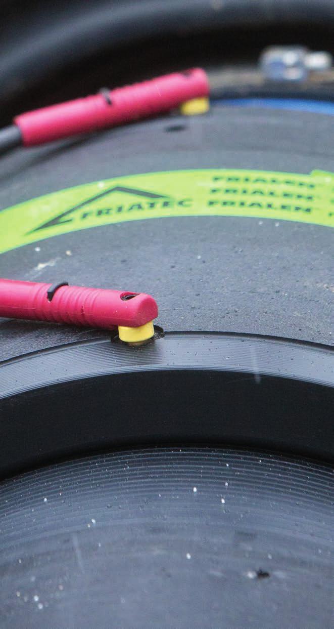
10 4.2 Measure fusion zone, mark with a FRIALEN marker and remove oxide layer (Figure 3) Fusion zone: The length of the fusion zone corresponds to half the length of the coupler. At first, remove contaminations from the pipe. A processing allowance of approx. + 5 mm in addition of the insertion depth provides proof after fusion that the oxide layer has been removed properly. Using a manual scraper or FRIATOOLS Scraper tools (see Figure 3, 4 a+b+c), the oxide layer, which is formed on the surface of HDPE pipes and spigot fittings during storage, has to be removed completely directly before the assembly. Figure 3 Figure 4a The scraper tools FWSG 710 L (d d 710), FWSG 900 L (d d 900) and FWSG XL (d d 1200, Figure 4a) facilitate the pipe processing across the entire slip-on length of the coupler. Short pipe spigots, e.g. at the fusion stub end, can be processed using FWSG 710S (Figure 4b). Figure 4b The scraper tools FWSG SE 250, 280 and 315 (Figure 4c) are proper for both, preparation of couplers-, and saddle assembly 10 Figure 4c
11 If the oxide layer is not removed completely, inhomogeneous, leaking fusion joints may result. A FRIATOOLS FWSG scraper tool must in all circumstances be used for fittings from d 710. Damages to the pipe surface as e.g. axial grooves or scratches may not be located within the fusion zone. An excessive swarf removal may result in an excessively large annular gap which either cannot or only insufficiently closed by fusion (for the remedy see item 4.8). Check regularly the condition of the blade at the manual scraper and the wear of the scraper blade at the scraper tool. Worn blades must be replaced (see FRIALEN Info No. 1). Scraper Tool Estimated swarf thickness (mm) Abrasion limit (mm) FWSG 225, SE >0.4 FWSG >0.5 FWSG 900L >0.5 FWSG XL (d ) >0.8 Please note that the indicated wearing margin applies to FRIALEN Safety Fittings. Where appropriate please observe manu facturers indications. Filing or sanding are not permitted because contaminations are introduced. For a control of the complete surface removal over the entire surface, we recommend to apply marking (control) lines (see Figure 3). If during scraping of the surface non-scraped areas occur at some points (e.g. in case of oval pipes), these areas are to be reworked. 11

 For this purpose, the manual scraper is a suitable tool.")
12 The processed zone is to be protected against dirt, soap, grease, subsequently flowing water and unfavourable effects of weather (e.g. moisture, frost formation). Do not touch the fusion zone again after scraping. FRIALEN Safety Fittings with integrated heating coils guarantee optimal heat transfer through their exposed heating coils and may thus not be scraped at the inside of the fitting. 4.3 External and internal chamfering of the cutting edge (See Figure 5) For this purpose, the manual scraper is a suitable tool. A good chamfer on the outside diameter of the face of the pipe will make it easier to fit the coupler. Remove swarves from within the pipe. 4.4 Restoration of irregular / oval pipes Pipes typically become irregular in the course of storage. If the pipe out-of-roundness in the fusion zone exceeds a maximum of 3 mm of the outer diameter, the pipe must be rounded in the fusion zone area. Please use rounding clamps for this purpose which are installed at the end of the fusion zone (see Figure 6), e.g. hydraulic rounding clamps FWXRH. Figure 5 Figure 6 12
.")
13 4.5 Cleaning The surfaces of the pipes to be fused and the interior surfaces of the FRIALEN Safety Fittings must be absolutely clean, dry and free from any grease. These areas are to be cleaned with a suitable cleaning agent and exclusively with ab sorbent, lintfree and non-dyed paper directly before the assembly and after scraping (see Figure 7). Figure 7 We recommend PE cleaning agents which are certified on the test basis DVGW-VP 603, e.g. AHK cleaning agents. When using alcoholic cleaning agents, the alcohol percentage must be at least 99.8% according to DVGW-VP 603. When cleaning, ensure that no contaminations from the unscraped pipe surface are introduced into the fusion zone. The amount of the cleaning agent is to be chosen such that the paper is slightly wetted. Skin contact is therefore to be avoided. Please observe the safety notes of the manufacturer! The cleaning agent must be completely evaporated before starting the fusion process. Now, using the FRIALEN marker, re-mark the line (approx. 120 dis tributed around the circumference) to show the width of the fusion zone on the pipe since this will have been removed by scraping and cleaning. The joint surfaces must be clean and dry before installing the fitting. The cleaned fusion zone should not be touched with bare hands. Moisture in the area of the joint area, e.g. because of dew or frost, is to be removed using suitable aids. 13
14 The fusion fitting is to be removed from the packaging only directly before the planned processing. The packaging protects the fittings against external influences during transport and storage. 4.6 Inserting spigot or pipe ends into the fitting. When the FRIALEN Safety Fittings and pipes are being assembled care should be taken to ensure that the contact sockets are accessible to allow connection of the fusion plug. Assembly can be assisted by tapping around the face with a plastic hammer at the same time. When assembling do not tilt. The worked insertion end must be pushed into the fitting up to the mark. If necessary round ing clamps should be used (see Figure 6). Repeated scraping of the outer dia meter might be necessary if the tolerance is big. Repeated scraping may not be performed to remedy installation problems due to out-of-roundness! If the fitting cannot be slipped on without using force despite the above described procedure, a repeated scraping is permitted. (see item 4.4). A simple control of the high points is possible by installing the coupler and evaluating the annular gap. 4.7 Ensuring a tension-free assembly of the components All joints prepared for fusion must be tension-free. Pipes may not be positioned in the FRIALEN Safety Fitting under bending stress or self-load. If required, the piping or the fitting is to be supported or suitable fixing facilities are to be used. The tension-free fixing of the joint is to be maintained until the cooling time stated on the barcode and in the table is reached. (see item 4.9). Before starting the fusion process, check again based on the markings whether the position of the pipe insertion end in the FRIALEN Safety Fitting has shifted (correct, if required). 14

15 A non-tension-free or shifted joint may result in an impermissible melt flow and a defective joint during fusion (see Figure 8). Figure Pre-heating for reducing the annular gap between coupler and pipe. Using the preheating barcode for couplers UB d 450 as well as UB PN25 d 280 after ring gap assessment (> 1 mm), the pipe can be adjusted to the coupler. For couplers from d 500, the preheating barcode must be used. UB-XL d 1000: For the couplers UB-XL d 1000, preheating and fusion are integrated in one single process. The 2-phase jointing process is controlled with a special barcode. Only use fusion units which have been approved by the manufacturer with regard to their function for the processing of FRIALEN Safety Fittings. See DVS For couplers from d 710, FRIAMAT electrofusion units, for UB-XL couplers d 1000 FRIAMAT XL electrofusion units must be used exclusively. Preheating barcode for UB d 900 (see also instruction leaflet enclosed with the component part). The ring gap between the coupler and the pipe can be compensated to a certain extent by using a specifically matched preheating barcode ( Figure 9). The maximum brid- Figure 9 15
16 geable distance between the coupler and the pipe may not exceed 3 mm across the entire circumference. For the coupler mounted and centred at the pipe, this means: d 6 mm. For relining slide-over couplers REM d110/dn100 and d160/dn150, a maximum gap of 2 mm applies. The thermal reduction of tensions in the joining area has also a positive effect on the fusion result. Procedure: 1. Preparation of the joining area corresponding to the FRIALEN installation instructions for large pipes and pipe network relining. 2. Centre the coupler on the pipe such that the ring gap across the circumference is as equal as possible. If required, support the coupler. 3. Close the ring gap with adhesive tape to prevent heat losses. 4. Close open pipe ends. 5. Standard processing: I. Preheating of first coupler side, record yellow barcode with FRIAMAT electrofusion unit and start the process; then II. preheating of second coupler side, record yellow barcode with FRIAMAT electrofusion unit and start the process; then III. first coupler side: check the ring gap: if it is still too large, the preheating can be repeated 2 x maximum. If ok: Start fusion of first coupler side, (white barcode), then IV. second coupler side: check the ring gap: if it is still too large, the preheating can be repeated 2 x maximum. If ok: Start fusion of second coupler side, (white barcode) 6. Observe cooling times according to item Between preheating and fusion, a waiting time is always required to ensure heating through of the component parts. This waiting time corresponds approximately to the preheating or fusion time, depending on the dimension approx minutes. If only one coupler side is to be processed, the waiting time between preheating and fusion is to be observed. If the waiting time is exceeded by more than the double time, the described process is to be repeated. 16

17 4.9 Carrying out the fusion Only use fusion units which have been approved by the man ufac tur er with regard to their function for the processing of FRIALEN Safety Fittings. See DVS Use FRIAMAT fusion units only for FRIALEN UB from d 710, for UB-XL d 1000 couplers only FRIAMAT-XL fusion units! Please observe oper ating instruction for FRIAMAT XL. For the fusion of the coupler d 800 and d 900 please observe our FRIALEN Info No. 42. The fusion parameters are contained in the main barcode affixed to the FRIALEN Safety Fitting. When using fully automatic fusion units (e.g. FRIAMAT), the parameters are entered into the fusion unit using the reader or barcode scanner. Figure 9a The subordinated barcode contains the data for component traceability. This barcode is to be read if the component traceability function is to be used. This requires suitable fusion units. The fusion units automatically monitor the fusion process and control the supplied energy in determined limits. The fusion parameters are encoded on the barcode label in the form of a 24-digit figure (top), the data for component traceability in the form of a 26-digit column of numbers (bottom), and can also be entered manually into the FRIAMAT fusion unit using the emergency entry mode. 17
18 Fusion units FRIAMAT L, FRIAMAT LE and FRIAMAT GEO are not suitable for the fusion of large couplers. For fittings with separate coils (see Figure 10), each fitting side is to be fused separately. For fittings with continuous coil, both fitting sides are to be fused si mul taneously (see Figure 11). FRIALEN Safety Fittings are equipped with a swell indicator, this only gives an indication that fusion has taken place. This swell indi cator signalises the fusion process, by changing its colour (red) and by increase of volume. The proper progress of the fusion process, however, is only shown by the fusion unit. After reading of the barcode, the fitting data are to be compared with the data shown on the unit s display. If they are identical, start fusion. Please observe the operating instruc tion of the FRIAMAT fusion unit. Avoid stress on the connecting spot. Figure 10 Figure 11 18
.")
19 CAUTION Keep a distance of one meter to the fusion site during the fusion process for general safety reasons. The obtained actual fusion time is to be compared with the target fusion time on the unit and to be noted on the pipe or the FRIALEN Safety Fitting (See Figure 12). Figure 12 With this identification it is ensured that no fusion point is overlooked. In case of interruption a fusion can be repeated. But the joint surfaces must be cooled down to ambient temperature before each renewed fusion. Please contact for this purpose your local FRIALEN sales engineer by phone or the FRIALEN Hotline Cooling times. The cooling time is a) the time which is required to cool down the component to the temperature which facilitates the movement of the joint. This time is also listed on the barcode and is identified by CT. b) the time which is required to cool down the component to the temperature which facilitates the application of the full test or operating pressure. This is classified into pressure volumes of up to 8 bar and > 8 bar. 19
20 When inserting piping (e.g. relining) it is the cooling time before pres surising which is important. Diameter in mm Cooling time in minutes for FRIALEN couplers and fittings CT Up to pressurising Up to pressurising until the joint at up to 8 bar at > 8 bar may be moved A piping may only be commissioned after successful pressure test (e.g. EN 805, EN and DVGW G 469, W 400). The detachment of the outer armouring wire during the cooling down stage is caused by the thermal expansion characteristics of the fused joint and does not present a problem. 5. Processing of saddle parts Top Loading FRIALEN TL saddle parts are used with pipes from SDR 17 to SDR 11 from d 250 mm. The processing occurs with the FRIATOP Clamping Unit (Figure 15b). 5.1 DAA-TL Pressure Tapping Tees - Top Loading, d (400) FRIALEN Pressure Tapp ing Tees Top-Loading DAA-TL are suitable for fitting as branch connectors onto unpressurised or pressurised pipelines. 20

21 FRIALEN pressure tapping valves d 355 mm may be processed using only SDR 17 and SDR 17,6 pipes due to tapping technique. Processing temperature: between 0 C and 45 C. Figure Measuring of fusion zone of the pipes (and the lateral outlet spigot), marking (Figure 13) and removing oxide layer The fusion zone: is the area of pipe covered by the saddle; for a side outlet it is the insertion depth on the smooth pipe spigot. The oxide layer in the area of the fusion zone, which has formed on the surface of the HDPE pipes during storage, must be totally re moved with a hand scraper (Figure 14) or a scraper tool e.g. FWSG SE (Figure 14a) immediately before assembly. A processing allowance of several millimetres in addition to the covered area provides proof after fusion that the oxide layer has been properly removed from the pipe. If the oxide layer is not removed completely, leaking fusion joints may result. Worn blades of the scraper tool and manual scraper must be replaced. A one-time, complete removal is sufficient (min mm). A uniform surface without flattening and sharp edges at the pipe diameter should be the result. Filing or sanding of the pipe is not permitted because contaminations are introduced. 21


22 For a control of the complete surface removal over the entire surface, we recommend to apply marking (control) lines (see Figure 14). If during scraping of the surface non-scraped areas occur at some points, these areas are to be reworked. The processed zone is to be protected against dirt, soap, grease, subsequently flowing water and unfavourable effects of weather (e.g. moisture, frost formation). Figure Cleaning The surfaces of the pipes to be fused and the interior surfaces of the FRIALEN DAA-TL Pressure Tapping Tees Top-Loading must be absolutely clean, dry and free from any grease. These areas are to be cleaned with a suitable cleaning agent and exclusively with absorbent, lint-free and non-dyed paper directly before the assembly and after scraping. Figure 14a We recommend PE cleaning agents which are certified on the test basis DVGW-VP 603, e.g. AHK cleaning agents. When using alcoholic cleaning agents, the alcohol percentage must be at least 99.8% pursuant to DVGW-VP 603. When cleaning, ensure that no contaminations from the unscraped pipe surface are introduced into the fusion zone. The amount of the cleaning agent is to be chosen such that the paper is slightly wetted. Skin contact is to be avoided. Please observe the safety notes of the manufacturer! The cleaning agent must be completely evaporated before starting the fusion process. 22

.")
23 Subsequently, re-apply marking line for the fusion zone width with the FRIALEN marker because this line was removed during scraping and cleaning. The joint surfaces must be clean and dry before installing the fitting. The cleaned fusion zone should not be touched with bare hands. Moisture in the area of the joint area, e.g. because of dew or frost, is to be removed using suitable aids. The fusion fitting is to be removed from the packaging only directly before the planned processing. The packaging protects the fittings against external influences during transport and storage. Figure 15a Assembly - Place the saddle onto the prepared surface of the pipe. - Fit the adapter of the FRIATOP clamping device (Figure 15a). - Fit the clamping device as directed in the Operating Instructions (Figure 15b). For pressure tapping tees and pressure tapping valves, the factory drill setting may not be changed before starting the fusion process Carrying out of fusion When fusing Pressure Tapping Tees to media-carrying pipings, the following operating pressures may not be exceeded until the pipe has cooled down completely: Figure 15b 23
24 Pipe material PE 80 PE 100 SDR Maximum permissible working pressure in bar Gas pipe Water pipe Only use fusion units which are authorised by their manufacturer to process FRIALEN Safety Fittings as part of their function. See DVS The fusion parameters are contained in the main barcode affixed to the FRIALEN Safety Fitting. When using fully automatic fusion units (e.g. FRIAMAT), the parameters are entered into the fusion unit using the reader. After reading of the barcode, the fitting data are to be compared with the data shown on the unit s display. If they are identical, start fusion. Please observe the operating instruction of the FRIAMAT fusion unit. The fusion units automatically monitor the fusion process and control the supplied energy in determined limits. The swell indicator only indicates to the performed fusion process. The proper fusion process is, however, only indicated by the fusion unit! CAUTION Keep a distance of one meter to the fusion site during the fusion process for general safety reasons. The obtained ACTUAL fusion time is to be compared with the target fusion time on the unit and to be noted on the pipe or the FRIALEN Safety Fittings. With this identification it is ensured that no fusion point is overlooked. After the fusion process has finish ed always maintain the jointing pressure for a 10 minute cooling period! 24

25 5.1.5 Removing of FRIATOP clamping unit, tapping and application of test and operating pressure Before FRIATOP clamping unit is removed after the fusion process the specific cooling time has to be observed, according to table: Diameter Cooling time in minutes for FRIALEN in mm Top-loading saddle fittings before removing Up to CT FRIATOP pressurisation Up to clamping unit via outlet tapping The cooling time CT stated on the fitting bar code corresponds to the cooling time until tapping. If the waiting times are not observed, leaking fusion joints may result. The general installation instructions must be observed before tapping Tapping of Pressure Tapping Tees Remove blanking plug. Turn the drill down up to the lower stop using the matching FRIALEN activating key (AF 19) (See Figure 16). Turn the drill backwards up to the upper stop. Position the blanking plug and turn down the FRIALEN activating key until the collar of the plug slightly touches the front face of the drill spigot. Subsequently, turn back the plug half a turn to relieve the O-ring tension. Figure 16 25
. 5.1.")
26 If the collar is excessively tightened, the plug may break or the hexa gonal seat may be overwound. In this case, the plug has to be replaced. We recommend closing the tapping dome with a fusion cap K. The required scraping and cleaning are to be performed (see items ) Tapping of DAV-TL pressure tapping valves d (Figure 17) Installation, fusion and cooling times as 5.1 et seq. Tap by turning the 14 mm square spanner clockwise up to lower end position. The valve is now closed. In order to open the valve, the tap must be moved anti-clockwise up to the end position. After arriving the end position turn back approx. half a rotation. The metal end points for the open Figure 17 or shut positions of the valve lead to a distinctly noticeable increase in the activating force. As sealing takes place in the closed position using a radially injected O-ring, it is not necessary to apply a great deal of pressure when closing the valve. Install the FRIALEN Installation Kit EBS on the 14 mm square of the DAV-TL and secure the splint against pull out. Set the required overlapping height on telescoping frame. Tele scoping frame may be adjusted by sliding scale and will stop securely at any point. The FRIALEN EBS is technically perfectly adapted to the FRIALEN DAV-TL. 26

27 5.2 VAM-RG-TL Valve Tapping Saddles d (560) Assembly The preparation of the installation and the fusion process is made analogue to the FRIALEN Pressure Tapping Tee (see 5. to 5.1.4). The fusion range of the saddle covers the dimensions d 250 up to d 560. If necessary application technology restrictions must be considered by drill tool. Details of these components, given by man u- fac tur er, have to be regarded. Figure 18 The cooling times are to be observed (see item Pressure Tapping Tee). The fitting is drilled using a suitable close-off device or fitted with a valve in accordance with the relevant Fitting Instructions from the different valve manufacturers. The preparation and conduct of the pressure test are carried out in accordance with the details given by the valve manufacturer. The threaded components fitted at the factory must be secured with a spanner to prevent them from twisting. Care should be taken to ensure that the insulation work is carried out in accordance with the regu lations (DVGW Standard Publi cation). 5.3 SPA-TL Shut off Saddles Top-Loading d (560) Assembly The fusion dimensions of the component includes d d 560. If necessary application tech no log i cal restrictions have to be regarded. For example by borer tool or balloon. Details of these components, given by man u fac tur er, have to be regarded. Processing temperature: between 0 C and 45 C. 27
 and observing the installation instruc tions of the tapping/shut-off saddle installation equipment of the relevant manufacturer.")

28 FRIALEN Shut-off Saddles (see Figure 19) are prepared for installation and fused analogue to FRIALEN Pressure Tapping Tees (see Chapters ). The tapping of the pipe can be made after cooling down (see item 5.1.5) and observing the installation instruc tions of the tapping/shut-off saddle installation equipment of the relevant manufacturer. Installing the brass plug The plug is to be screwed in such that the O-ring seals in the dome. In the end position, the plug protrudes from the dome sleeve by approx. 1.5 mm (Figure 20). Screwing in requires a torque of approx. 150 Nm. This can be obtained using a suitable tool aided, if required, by a lever. After fitting the brass plug either the plastic nut must be screwed on or a FRIALEN cap for Shut off Saddles must be fused on, ensuring that the usual scraping and cleaning work is carried out (see Figure 21). Figure 19 Figure SA-TL Spigot Saddles Top-Loading d Assembly The preparation of the installation and the fusion process is made analogue to the FRIALEN Pressure Tapping Tee (see ). Figure Figure 22
, especially designed for this purpose. Please ask our FRIALEN Application Engineering Department.")
29 The tapping is made with commercially available tapping units in an unpressurised state with or under pressure using shut-off valves. We recommend the tapping unit of the company of Hütz + Baumgarten, Remscheid ( especially designed for this purpose. Please ask our FRIALEN Application Engineering Department. The manufacturer s installation instructions are to be observed. 5.5 VSC-TL Repair Saddle Top-Loading d Assembly For localised damage to the pipe at a single point the damaged spot can be sealed off with a plug and then fused with the repair Saddle Top-Loading. The preparation of the installation and the fusion process of the individual half shells is made analogue to the FRIALEN Pressure Tapping Tee (see ). Figure 23 Care must be taken to ensure that during assembly the damaged or deformed point on the pipeline lies in the centre of the heating element and is at least 10 mm away from the interior heating coil. Fusion with escaping media is not permissible. 29

30 5.6 AKHP-TL Tapping Ball Valves d (560) AKHP-TL Tapping Ball Valves allow the drilling of unpressurised or pressurised pipelines. The fusion zone of the component includes the dimensions d d 560. If necessary application technological restrictions have to be regarded. For example by borer tool or balloon, normally ap pli ca ble up to d 315 SDR 11. Details of these components, given by man u factur er, have to be regarded. Figure Assembly The preparation of the installation and the fusion process of the tapping ball valve AKHP is made as saddle component analogue to the FRIALEN Pressure Tapping Tee (see items ). For a leakage-free tapping of pressurised pipings, we recommend the tapping unit of the company of Hütz + Baumgarten, Remscheid ( Please ask our Application Engineering Department. The telescopic FRIALEN-actuation key BS is particularly designed for the technical and geometrical requirements of the KHP ball valve. 6. Working with SA-XL saddle fittings using a vacuum clamping technique FRIALEN spigot saddles SA-XL are used as tapping tees for connecting branch piping to main pipelines. They are suitable for use with standard piping with a diameter of > 250 mm. The VACUSET XL can be deployed in a temperature range between -10 C and +45 C and up to a maximum altitude of 1000 m. Please contact our Application Engineering department regarding any deviating operating conditions. 30

31 Temporary discrepancy in the installation instructions: The tapping tees are clamped onto the pipe with a vacuum technique using a vacuum pump, which is provided by FRIATEC. The tapping tees are clamped onto the pipe with a vacuum technique using the FRIATOOLS VACUSET XL. A compressor is required to create the vacuum. Please observe the compressor manufacturer s instructions with regard to permitted ambient operating temperatures. Non-pressurised piping is tapped using the FRIATOOLS drilling device FWAB XL. The piping must be completely drained (without any medium) before tapping it. Special tapping equipment is required for tapping pressurised piping; please contact our Application Engineering department for information. 6.1 Assembly The preparation for fusing saddle parts is the same as for the FRIALEN pressure tapping tee (see sections ). The assembly using the vacuum clamping technique is described in the FRIATOOLS VACUSET XL operating instructions. Place the FRIALEN XL spigot saddle SA-XL with the saddle area on a clean surface (e.g. on a box) and assemble the equipment as described below. Insert the plunger into the flanged outlet and seal the pipe spigot (see Figure 25). Figure 25 31
 that the fill levels of the fuel tanks for the generator and the")


32 Connect the vacuum hoses (Figure 26). Switch the compressor on. Check the usability of the components, taking particular care to ensure that the hose connections do not leak and (where applicable) that the fill levels of the fuel tanks for the generator and the compressor are satisfactory. Place the FRIALEN spigot saddle SA-XL onto the prepared surface of the pipe. Make sure that the seal in the saddle is positioned correctly! Figure 26 It may not be possible to create a vacuum with excessively oval piping. Then press the saddle onto the pipe using two tensioning straps by positioning them on the sides of the saddle and aligning them so they are straight. When a constant vacuum of at least -0.8 bar is displayed, loosen the tensioning belts and remove them. Figure 27 Make sure that the FRIALEN spigot saddle SA-XL is positioned correctly. The vacuum must be at least -0.8 bar (absolute < 0.2 bar) during the entire procedure (approx. 45 minutes) until the end of the cooling period (see Figure 27). The saddle must initially be clamped onto the pipe under a vacuum Figure 28 for a holding time of at least 2 minutes. Make a note of the holding time on the pipe or fitting. Start the preheating process after reading in the yellow barcode. Make a note of the preheating time on the pipe or fitting. 32
33 Start the fusion cycle straight after the preheating process has finished (Figure 28). Make a note of the fusing time on the pipe or fitting. After the fusion cycle has been completed, the parts must cool down for 30 minutes while clamped under vacuum. Make a note of the cooling time and the manometer reading on the pipe or fitting. 6.2 Tapping Depressurised and completely drained pipes are tapped using the FRIATOOLS drilling device FWAB XL. The following waiting times must be observed: Diameter in mm Cooling time in minutes for FRIALEN saddle fittings XL From the end of the Until fusion cycle until tapping pressurisation (clamped under vacuum) via the outlet (CT) The cooling times (CT) labelled on the components correspond to the cooling time until the pipe is ready for tapping. Observe the instructions in the operating instructions for the FRIATOOLS drilling device FWAB XL! DANGER It is forbidden to tap pipes containing explosive mixtures (e.g. residual gas, sewer gas). DANGER Make sure that there is no residual water or any other medium in the piping, particularly when tapping the bottom of the pipe for drainage connections. The medium could flow straight into the drill during tapping. 33
34 7. Pipeline relining 7.1 Procedures and areas of application Defective old pipelines made of cast iron, steel or other conventional materials can be renovated by drawing in an HDPE pipe, as an alternative to laying new pipes. Standard pipes are used for the relining process and are joined using suitable FRIALEN Safety Fittings. For the so-called close-fit process (lining with precisely fitting pipes), however, the pipes which are used have a cross section which has been changed in the manufacturing process (e.g. U-liners) or on the building site itself (e.g. Swage lining). The outside diameter of these pipes is matched to the inside diameter of the old pipeline and thus deviates from the standard. The ends of each renovated section of pipeline can be fused with FRIALEN REM Relining Slide-over Couplers. At points where it is scheduled to fuse on a coupler or a saddle the relining pipe should be sized to the nominal inside diameter during the reshaping by fitting half shells. 7.2 REM Relining Adapter Couplers One end of the REM Relining Adapter Coupler (Figure 29) is matched to the dimensions of the pipes used for this process. The other end corresponds to the standard pipe size. This allows renovated sections of pipeline to be connected using fitted pieces of standard pipe. The fittings are used like slide-over couplers. Figure Fitting and fusion Relining using HDPE standard pipes When joining standard pipes the appropriate FRIALEN Safety Fittings are used. The fitting and fusion is carried out in a similar fashion to that in item 4. For couplers > d 250 mm preheating in accordance with item 4.8 is recommended when there are larger annular gaps. 34
35 7.3.2 Close-fit relining After the renovation the HDPE pipes used will often exhibit deviations both in their diameter and from the ideal round shape in the area of the pro posed joint. Depending on the charac teristics of the pipe the joint can be made using a preheating code, and also in conjunction with a support sleeve or a pipe expander tool Pre-heating: Procedure see item Support sleeve In case of larger deviations in shape or size on the ends of the pipes in the area of the joint the use of support sleeves is recommended (Figure 30). The fitting can then be used as a slide-over coupler. For fitting the support sleeve a suitable pipe expander tool has to be employed (Figure 31). Before using the pipe expander tool deviations in shape must be taken into account. The expander shells should be positioned to give an optimum rounding effect. The design of the support sleeve is dependent on the medium flowing, the material and the pipe size. The fitting of coupler and sleeve will be made easier if the pipe tolerances are taken into account when deciding on the size. The use of preheating in accordance with item will then be essential. Figure 30 Figure 31 Pipe expander tool Figure 32 35
 is particularly important to reduce the stresses in the pipe.")
36 7.3.5 Use of a pipe expander tool as a temporary support sleeve If a support sleeve is not wanted the coupler can be fused using a suitable pipe expander tool, matched to the size of the pipe. Use of the preheating barcode (see item 7.3.3) is particularly important to reduce the stresses in the pipe. The tool must remain in place during the fusion process and until the cooling period has passed. 7.4 Cooling times For cooling times item 4.10 is appli cable. 7.5 Relining fittings and clips (top loading) When fitting saddle components ( Figure 33) care must be taken with any ovality or flattening of the HDPE pipe. In order to achieve a uniform surface pressure, and thus a proper fusion, the radius of curvature on the inner liner at the site of the proposed Figure 33 joint must correspond to the diameter range d of the moulded component being used. If necessary the saddle must be brought into line either axially or radially. For the particular fitting dimension please refer to our FRIALEN product range. The assembly of the saddle components occurs according to items to Before the renovation the old pipe should be cut away at the point where a moulded saddle component is to be fused to the inner liner pipe. The pipe diameter will be brought to size at the proposed jointing point by fitting half shells. When fitting a house connection at some later point access to the inner liner is gained by using a window cutter to get through the old pipe.
37 8. Update of these assembly instructions Further operating and assembly instructions are available: - FRIALEN Safety Fittings for House Service and Supply pipings up to d FRIAFIT Sewage System - FRIAMAT Electrofusion Units - FRIATOOLS Scraper Tools - FRIATOP Clamping Unit - FWFIT Clamping and Tapping Tool - VACUSET XL Vacuum clamping unit - FWAB XL Drilling device - FWXRH Rounding clamp - FWXRB Rounding clamp These technical statements are regularly revised to be up-to-date. The date of the last revision is stated on the document. You will find the updated assembly instructions on our website as pdf documents. We will also mail them to you on request. 37
38 38
39 39
40 FRIATEC Aktiengesellschaft Technical Plastics Division P.O.B Mannheim Germany Tel Fax
FRIALEN Safety Fittings for House Service and Supply pipings up to d 225. Assembly Instructions
 FRIALEN Safety Fittings for House Service and Supply pipings up to d 225 Assembly Instructions Contents Page FRIALEN Safety Fittings: 1. Safety 3 2. Areas of application 3 3. Regulations and processing
FRIALEN Assembly and Operating Instructions. for FRIATOP clamping unit (Top-Loading) FRIATOOLS
 FRIATOOLS") FRIALEN Assembly and Operating Instructions for FRIATOP clamping unit (Top-Loading) FRIATOOLS The FRIATOP clamping unit Tensioning belt Top loading component (e. g. tapping ball valve) Adapter Pressure
FRIALEN Assembly and Operating Instructions for FRIATOP clamping unit (Top-Loading) FRIATOOLS The FRIATOP clamping unit Tensioning belt Top loading component (e. g. tapping ball valve) Adapter Pressure
APG001. Application Guide for Gas. T: F: E:
 APG001 Application Guide for Gas T: 01480 442600 F: 01480 458829 E: customerservice@gpsuk.com www.gpsuk.com Application Guide for Gas Introduction 3-4 Range Overview 5-6 PE80 Yellow Pipe 7-9 Excel Yellow
Instruction Manual. PE-25/32/37 Tapping Machines. POLYTAPP Valves
 Instruction Manual PE-25/32/37 Tapping Machines & POLYTAPP Valves Nov 2016, Revision 2 Document Number 3000111 2 M.T. Deason Company, Inc. PO Box 101807 Birmingham, AL 35210 Phone: 205 956 2266 Fax: 205
with self-sealing gas valve system
 with self-sealing gas valve system R DUCTILE PVC POLSAFE GAS DISTRIBUTION SYSTEM INTRODUCTION POLSAFE is a programme of fittings for low pressure gas distribution systems. POLSAFE is designed for 25 up
PE Shut-Off Valve FRIALOC PE 100 / SDR 11 PFA/PN 16 bar d 90, d 110, d 125, d 160, d 180 FRIALEN. FAQ: Answers to frequently asked questions
 PE Shut-Off Valve FRIALOC PE 100 / SDR 11 PFA/PN 16 bar d 90, d 110, d 125, d 160, d 180 FRIALEN FAQ: Answers to frequently asked questions FAQ: Answers to frequently asked questions Question 1: What are
Engineering Data Sheet
 Page 1 of 6 CE MARKING AND THE PRESSURE EQUIPMENT DIRECTIVE 97/23/EC Valves must be installed into a well designed system and it is recommended that the system be inspected in accordance with the appropriate
Declaration of Conformity as per Directive 97/23/EC
 Declaration of Conformity as per Directive 97/23/EC The manufacturer declares that:, 47906 Kempen, Germany Multi-way diverting valves Series 29a and Series 29b, with packing with lever 1. The valves are
FUSAMATIC MULTISEAL TAPPING TEE STACKLOAD OR UNDERCLAMP FOR GAS AND WATER....Connect
 FUSAMATIC MULTISEAL TAPPING TEE STACKLOAD OR UNDERCLAMP FOR GAS AND WATER...Connect FUSAMATIC MULTISEAL TAPPING TEE FOR GAS AND WATER Fusion Group Limited pioneered polyethylene pipe jointing in the UK
IAPMO GUIDE CRITERIA FOR BALL VALVES IAPMO IGC PURPOSE
 INTERNATIONAL ASSOCIATION OF PLUMBING AND MECHANICAL OFFICIALS IAPMO GUIDE CRITERIA FOR BALL VALVES IAPMO IGC 157-20067 1 PURPOSE 1.1 The purpose of this standard is to establish an acceptable standard
Installation, operation & maintenance manual - original version
 Installation, operation & maintenance manual - original version AVK gate valves for water and wastewater Series 01, 02, 06, 12, 15, 18, 20, 26, 32, 33, 36, 38, 50, 55 and 636 COPYRIGHT AVK GROUP A/S 2018
General page Straight unions page Angle unions page Tee and L-unions page Gauge connection unions page 42
 C 2610-00 Table of contents General page 3-13 DILO unions for pressure ranges from 100 320 bar Straight unions page 14-25 Weld-on tube unions page 14-16 Screw-in tube unions page 17-25 with metric / Whitworth-
Geopress. Instructions for Use. Year built: from 01/2004 en_int
 Geopress Instructions for Use Year built: from 01/2004 en_int Geopress 2 from 26 Table of contents Table of contents 1 About these instructions for use 4 1.1 Target groups 4 1.2 Labelling of notes 4 1.3
PSI Mechanical Couplings
 Pipeline Accessories PSI Mechanical Couplings Systems Permasert and PermaLock Permasert and Permalock are Elster Perfection registered trade marks General Information Technical Data Installation Instructions
AREA VALVE SERVICE UNITS
 AREA VALVE SERVICE UNITS. Unit 8, McKenzie Industrial Park, Tel No.: 44 (0) 161 428 7200 Bird Hall Lane, Fax No.: 44 (0) 161 428 7010 Stockport, Email: info@p3-phoenix.com U.K., SK3 0SB www.p3-phoenix.com
MUELLER. Mega-Lite Drilling Machine. Reliable Connections. table of contents PAGE. Equipment 2. Operating Instructions 3-4. Parts Information 5
 operating Instructions manual MUELLER Mega-Lite Drilling Machine table of contents PAGE Equipment 2 Operating Instructions 3-4 Parts Information 5 Travel Charts 6-11! WARNING: 1. Read and follow instructions
tubepress press procedure
 tubepress press procedure tubepress 15mm up to 35mm tubepress 15 mm up to 35 mm 1. The tube ends must be clean with no scratches or grooves. Remove end caps. Cut tube to length. 2. Deburr tube inside and
Pressure relief valve
 Pressure relief valve Operating manual Series DHV 718 Version BA-2016.01.11 EN Print-No. 300 524 TR MA DE Rev001 ASV Stübbe GmbH & Co. KG Hollwieser Straße 5 32602 Vlotho Germany Phone: +49 (0) 5733-799-0
Translation of the original Operating Instructions for HKS rubber compensators
 Because of their flexible elements and mechanisms, HKS rubber compensators are susceptible to damage of all types and adverse loads in operation. For reliable operation of a compensator and, thus, the
better measurement Simply a question of SCHMIDT Flow Sensor SS The cost-effective alternative in pressurised systems up to 10 bars.
 Simply a question of better measurement SCHMIDT Flow Sensor SS 20.261 The cost-effective alternative in pressurised systems up to 10 bars. Compressed air technology Industrial processes A cost analysis
Installation & Operation Manual Proven Quality since 1892
 Content 1. ERIKS operating companies 2. Product description 3. Requirements for maintenance staff 4. Transport and storage 5. Function 6. Application 7. Installation 8. Maintenance 9. Service and repair
DR.ING. CARLO AVANZINI PROFESSIONAL ENGINEER GRIP TEST REPORT NOVA SIRIA, ROLETTO, Premise
 GRIP TEST REPORT NOVA SIRIA, ROLETTO, 07.10.2013 1. Premise The present report covers the witnessing of the test conducted in the Nova Siria Factory in Roletto (Torino, Italy) to verify the behavior of
Mounting and Operating Instructions EB 2558 EN. Self-operated Pressure Regulators. Type Pressure Build-up Regulator
 Self-operated Pressure Regulators Type 2357-31 Pressure Build-up Regulator with safety function and integrated excess pressure valve Type 2357-31 with non-return unit at port C Ports A and B with soldering
Type BBS-03, BBS-05, BBS-06, BBS-25
 Type BBS-03, BBS-05, BBS-06, BBS-25 Sterile connection elements Sterile Verbindungselemente Raccords union stériles Operating Instructions Bedienungsanleitung Manuel d utilisation 1. THE OPERATING INSTRUCTIONS
APT Electrofusion Ducting
 APT Electrofusion Ducting Installation Guide Franklin Fueling Systems 3760 Marsh Rd. Madison, WI 53718 USA Tel: +1 608 838 8786 800 225 9787 Fax: +1 608 838 6433 www.franklinfueling.com Safety Important!
Declaration of Conformity as per Directive 97/23/EC
 Declaration of Conformity as per Directive 97/23/EC The manufacturer declares that:, 47906 Kempen, Germany Continuous, inline sampling valves Series 27f, with packing Operate with either; Star lever, or
Hot Tapping Machine. OPERATIONS MANUAL and OPERATING INSTRUCTIONS
 262-2040 Hot Tapping Machine For performing 1/4 6 Hot taps 285 psi or less. Municipal Water, Sewage, & Building Services Use OPERATIONS MANUAL and OPERATING INSTRUCTIONS WARNING: These instructions are
M03 WUNDATRADE. Heat Pump Manifold. Before you start: Check the contents. Optional. ...a division of WUNDA GROUP PLC
 Before you start: Check the manifold box contents against the list below. Check the contents Flow gauges 1. Bar assembly with manual return valves 2. 2 x Auto air vent & drain hose attachments Optional
Type Operating Instructions. 2/2-way solenoid valve 2/2-Wege Magnetventil Electrovanne 2/2 voies.
 2/2-way solenoid valve 2/2-Wege Magnetventil Electrovanne 2/2 voies We reserve the right to make technical changes without notice. Technische Änderungen vorbehalten. Sous réserve de modifications techniques.
Two-stage valve type NE
 Two-stage valve type NE Product documentation Operating pressure pmax: Flow rate Qmax: 700 bar (High pressure) 80 bar (Low pressure) 25 lpm (High pressure) 180 lpm (Low pressure) D 7161 03-2017-1.0 by
VERTICAL AIR COMPRESSORS
 VERTICAL AIR COMPRESSORS MODEL NO: VE11C150, VE15C150, VE18C150 PART NO: 2226005, 2226000, 2226015 OPERATION & MAINTENANCE INSTRUCTIONS LS0615 INTRODUCTION Thank you for purchasing this CLARKE Vertical
Mounting and Operating Instructions EB 3007 EN. Self-operated Pressure Regulators. Differential Pressure Regulators (opening) Type Type 42-25
 Type Type 42-25") Self-operated Pressure Regulators Differential Pressure Regulators (opening) Type 42-20 Type 42-25 Type 42-20 Differential Pressure Regulator Type 42-25 Differential Pressure Regulator Mounting and Operating
Self-operated Pressure Regulators Differential Pressure Regulators (opening) Type 42-20 Type 42-25 Type 42-20 Differential Pressure Regulator Type 42-25 Differential Pressure Regulator Mounting and Operating
Gas Welding Hoses and connections, the weak link
 Gas Welding Hoses and connections, the weak link By Leif Andersen, Technical Product Manager Welding, WSS Regulators with flashback arrestors and the shank with its welding or cutting attachment are made
VERTICAL AIR COMPRESSORS
 VERTICAL AIR COMPRESSORS MODEL NO: VE15C150, VE18C150, VE25C150 PART NO: 2226010, 2226020, 2226025 OPERATION & MAINTENANCE INSTRUCTIONS LS0715 INTRODUCTION Thank you for purchasing this CLARKE Vertical
Wafer Check Valve. Contents. User s Manual. (1) Be sure to read the following description of our product warranty 1
 Be sure to read the following description of our product warranty 1") Serial No. H-V066-E-3 Wafer Check Valve User s Manual Contents (1) Be sure to read the following description of our product warranty 1 (2) General operating instructions 2 (3) General instructions for
Serial No. H-V066-E-3 Wafer Check Valve User s Manual Contents (1) Be sure to read the following description of our product warranty 1 (2) General operating instructions 2 (3) General instructions for
Mounting and operating instructions EB 2530 EN. Self-operated Pressure Regulator. Pressure Reducing Valve Type M 44-2
 Self-operated Pressure Regulator Pressure Reducing Valve Type M 44-2 Type M 44-2, connection G 1 4, K VS = 0.15 Type M 44-2, connection G 1, K VS = 6 Fig. 1 Type M 44-2 Pressure Reducing Valve Mounting
HUPF Series DESCRIPTION APPLICATION INSTRUCTION SHEET GAS PRESSURE REGULATOR WITH INCORPORATED FILTER EN1C-0003NL05 R1205.
 HUPF Series GAS PRESSURE REGULATOR WITH INCORPORATED FILTER INSTRUCTION SHEET DESCRIPTION Spring-loaded regulator with inlet pressure compensation and zero shut-off. The outlet pressure is kept constant
Declaration of Conformity as per Directive 97/23/EC
 Declaration of Conformity as per Directive 97/23/EC The manufacturer declares that:, 47906 Kempen, Germany Discontinous, inline sampling valves Series 27a and Series 27g, with packing with lever (180 )
Operating Instructions in compliance with Pressure Equipment Directive 2014/68/EU. FAS Brass Check Valve RDL
 Operating Instructions in compliance with Pressure Equipment Directive 2014/68/EU FAS Brass Check Valve RDL Please read these operating instructions carefully to ensure a safe operation and keep the same
Instruction manual. for. high purity gas pigtails 200 bar / 300 bar
 Instruction manual for high purity gas pigtails 200 bar / 300 bar Contents Contents... 2 1. Preface... 3 1.1 Overview... 3 1.2 General... 3 1.3 Intended use... 4 1.4 Personnel requirements... 4 2. For
Gas plug-in hose, straight-through form. Instructions for Use. suitable for gas socket model G2019T, G2016T. G2023 from 01/1990.
 Gas plug-in hose, straight-through form Instructions for Use suitable for gas socket model G2019T, G2016T Model Year built: G2023 from 01/1990 en_int Gas plug-in hose, straight-through form 2 from 12 Table
Pressure relief valve
 Pressure relief valve Operating manual Series DHV 712 R Version BA-2016.01.19 EN Print-No. 300 472 TR MA DE Rev001 ASV Stübbe GmbH & Co. KG Hollwieser Straße 5 32602 Vlotho Germany Phone: +49 (0) 5733-799-0
MoveRoll Conveyor Operating and Maintenance Manual
 MoveRoll Conveyor Operating and Maintenance Manual 1. Read this first! This manual contains information for protection of personnel in the roll handling area from possible injury and/or equipment damage.
Spilt body Flange ball valve. TC-205MFF-PN1640 User Manual English Version. Document No: TC-205MFF-PN1640.Ur-manual. Date: 2007/04/2617. Version: 1.
 Spilt body Flange ball valve TC-205MFF-PN1640 Series PED Category I,II TC-205MFF-PN1640 User Manual English Version Use for company in Europe who will place the product on the market, please amend which
Coiling Tube with Twist-Proof Fitting
 http://www.pisco.co.jp FITTING CONTROLLER VALVE TUBE MAKE-TO-ORDER PRODUCTS Push-In Fitting Type Anti-Twisting Coiling Tube for Air Tool Coiling Tube with Twist-Proof Fitting 306 Avoid Twisted Tube Problem
Mounting and Operating Instructions EB 2172 EN. Series 43 Temperature Regulators. Type 43-5 and Type Type Type 43-6
 Series 43 Temperature Regulators Type 43-5 and Type 43-7 Type 43-6 Type 43-6 Type 43-7 with flanged valve body, DN 32 to 50 Type 43-5 Type 43-7 with welding ends Mounting and Operating Instructions EB
Photo: Jonas Wall ANTARES OVAL DRY GLOVE SYSTEM BY SI TECH.
 Photo: Jonas Wall ANTARES OVAL DRY GLOVE SYSTEM BY SI TECH www.sitech.se The Oval revolution We want to congratulate you on your purchase of the ANTARES Modular Dry Glove System. The oval design and quick
Ball valve HKSF-W100. Ball valve HKSF-W100. RMA Kehl GmbH & Co. KG Oststrasse 17 D Kehl / Germany
 Ball valve HKSF-W100 RMA Kehl GmbH & Co. KG Oststrasse 17 D-77694 Kehl / Germany info@rma-kehl.de www.rma-armaturen.de 1 Design Features: RMA-ball valves type HKSF-W are fully welded and completely maintenance-free
Rapidmain Installation Guide
 Rapidmain Installation Guide Aluminium Compressed Air Pipe Work Installation Guide Trafalgar Court, Waterloo Ind Estate, Widnes Cheshire. UK. Ref: Rapidmain installation guide 4b Index 1. Rapidmain fittings:
Mounting and Operating Instructions EB EN. Type Supply Pressure Regulator. with increased air capacity
 Type 4708-45 Supply Pressure Regulator with increased air capacity Translation of original instructions Mounting and Operating Instructions EB 8546-1 EN Edition March 2016 Note on these mounting and operating
Mounting and Operating Instructions EB 3017 EN. Self-operated Regulators
 Self-operated Regulars Flow and Differential Pressure Regular Type 42-37 Flow and Differential Pressure or Flow and Pressure Regular Type 42-39 Type 42-37 Type 42-39 Fig. 1 Flow and differential pressure
Pressure Reducing Valve
 ASV Stübbe GmbH & Co. KG Hollwieser Straße 5 D-32602 Vlotho Fon +49 (0) 57 33-7 99-0 Fax +49 (0) 57 33-7 99-2 00 www.asv-stuebbe.de contact@asv-stuebbe.de Advantages high reproducibility of setting pressure
VRB00 Series CLASS B SERVO REGULATED COMBINATION VALVES
 GAS VALVES VRB00 Series CLASS B SERVO REGULATED COMBINATION VALVES APPLICATION PRODUCT HANDBOOK The VRB00 Series class B servo regulated combination valves are used for control and regulation of gaseous
Flamco Flamco-Fill STA Flamco-Fill STM
 STA STM Typ STA 5936 Typ STM 5937 GB Installation and operating instructions 1999, 2 Contents GB UK Limited P.O. Box 9, Washway Lane, St. Helens, Merseyside WA10 6FE United Kingdom Telephone: 01744 744744
Operating instructions Safety Rope Emergency Stop Switches ZB0052 / ZB0053 ZB0072 / ZB0073
 Operating instructions Safety Rope Emergency Stop Switches UK ZB0052 / ZB0053 ZB0072 / ZB0073 7390878 / 02 03 / 2011 Contents 1 Safety instructions...3 2 Installation / set-up...4 2.1 Applications...4
HDPE. Dredging Pipeline
 HDPE Dredging Pipeline R Ace Flowtech Co., Ltd Office address: No.2, 2-1601, Rongyuan Road, Huayuan Industrial Park, Tianjin Binhai Hi- Tech Area, Tianjin City, China, 300384 Factory address: No.51 Lutai
SEries 29 Hydrant valves installation, operation & maintenance manual
 Instruction for use Thank you for selecting an AVK product. With correct use, it will give long and reliable service. This manual has been prepared to assist you install, operate and maintain the valve
Pressure Dump Valve Service Kit for Series 3000 Units
 Instruction Sheet Pressure Dump Valve Service Kit for Series 000 Units. Overview The Nordson pressure dump valve is used to relieve hydraulic pressure instantly in Series 00, 400, 500, and 700 applicator
Installation and Maintenance Instruction Manual
 Installation and Maintenance Instruction Manual Bi-metal Thermometer Model A and E in a configuration - pursuant to ASME B40.200: ##=E#=### or ##=ERT#=### - pursuant to EN 13190: ###=A#=### or ##=ART#=###
Pressure Dump Valve Service Kit for Series 2300 Units
 Instruction Sheet Pressure Dump Valve Service Kit for Series 00 Units. Overview The Nordson pressure dump valve is used to relieve hydraulic pressure instantly in Series 00 applicator tanks when the unit
Operating Procedures for GripTight 15.5 SDR & IPS Test Plugs
 EST Group DC2518 08/01 REV 3 12/12 Page 1 of 6 Operating Procedures for GripTight SDR & IPS Test Plugs WARNING For proper operation, GripTight plugs must be assembled as shown in Figure 1. Pressure testing
Type 0404 / /2-way solenoid valve 2/2-Wege-Magnetventil Électrovanne 2/2 voies Operating Instructions Bedienungsanleitung Manuel d utilisation
 Type 0404 / 5404 2/2-way solenoid valve 2/2-Wege-Magnetventil Électrovanne 2/2 voies Operating Instructions Bedienungsanleitung Manuel d utilisation 1 OPERATING INSTRUCTIONS The operating instructions
750 Cable Cutter INSTRUCTION MANUAL
 INSTRUCTION MANUAL 750 Cable Cutter Read and understand all of the instructions and safety information in this manual before operating or servicing this tool. Register this product at www.greenlee.com
DVS Technical Codes an Bulletins
 DVS Technical Codes an Bulletins DVS 1904-1 (2010-02) Adhesive bonding of plastics in domestic installation Requirements on plants and personnel... 1 DVS 1904-2 (2010-02) Adhesive bonding of plastics in
Owner s Guide. ElevateSUP.com
 Owner s Guide ElevateSUP.com IMPORTANT READ THIS IMPORTANT INFORMATION BEFORE USING YOUR STAND UP PAD- DLEBOARD Disregarding any of the safety precautions and instructions contained in the owner s manual
RARS5000 AIR BODY SAW OWNER S OPERATING MANUAL
 RARS5000 AIR BODY SAW OWNER S OPERATING MANUAL DESCRIPTION 1. No mar 2. No mar tip 3. Housing grip 4. Trigger 5. Air inlet 6. Air inlet plug 7. Plastic board Important! It is essential that you read the
Continental Industries TRANSITION FITTINGS or FAX Visit
 Continental Industries TRANSITION FITTINGS 1-800-558-1373 or FAX 1-800-788-1668 Visit www.conind.com ABOUT US Our Company Continental Industries, headquartered in Tulsa, Oklahoma, was formed in 1958 and
Ball valve. Operating instructions for series. Version BA Print-No TR MA DE Rev001
 Ball valve Operating instructions for series Version BA-2016.02.05 Print-No. 300 587 TR MA DE Rev001 We reserve the right to make technical changes. Read carefully before use. Save for future use. ASV
Dual Solenoid Gas Valve Installation
 Installation IMPORTANT: These instructions are intended as a guide for qualified personnel installing or servicing FLYNN Gas Products. Carefully follow all instructions in this bulletin and all instructions
TECHNICAL DATA. Q = C v P S
 January 6, 2012 Preaction 348a 1. Description Viking supervised Surefire Preaction Systems utilize the Viking G-6000P Valve. The small profile, lightweight, pilot operated Viking G-6000P Valve comes complete
OPERATING MANUAL CHEMTRAC 840M MANUAL RETRACTABLE PROCESS HOLDER
 OPERATING MANUAL CHEMTRAC 840M MANUAL RETRACTABLE PROCESS HOLDER Table of contents 1 Security and safety measures... 5 1.1 General safety instructions... 5 1.2 Intended use... 5 1.3 Danger zones and residual
97C COMPRESSOR KIT 12V PART NO C COMPRESSOR KIT 24V PART NO C COMPRESSOR KIT PART NO
 97C COMPRESSOR KIT 12V PART NO. 00097 97C COMPRESSOR KIT 24V PART NO. 02497 98C COMPRESSOR KIT PART NO. 00098 97C 98C IMPORTANT: It is essential that you and any other operator of this product read and
CRANKSET 1 - TECHNICAL SPECIFICATIONS 2 - COMPATIBILITY CHAIN LINE SIZE 53/39-55/42-54/42 BORA ULTRA. 11s BORA ULTRA CRANKSET
 BORA ULTRA 1 - TECHNICAL SPECIFICATIONS 53/39-55/42-54/42 BOLT CIRCLE DIAMETER CHAIN LINE MINIMUM CHAINSTAY LENGHT AXLE THREADS 1.1 - CHAIN LINE SIZE Chain line for double crankset (Fig, 1) LINEA CHAIN
Steam trap BK 37 BK 28 BK 29 BK 37 ASME BK 28 ASME BK 29 ASME
 Steam trap BK 37 BK 28 BK 29 BK 37 ASME BK 28 ASME BK 29 ASME Original Installation Instructions 818689-05 Contents Foreword... 3 Availability... 3 Formatting features in the document... 3 Safety... 3
Industry Guidelines POLYETHYLENE (PE) PIPES AND FITTINGS FOR COMPRESSED AIR ISSUE 6.8
 PIPES AND FITTINGS FOR COMPRESSED AIR ISSUE 6.8") Industry Guidelines POLYETHYLENE (PE) PIPES AND FITTINGS FOR COMPRESSED AIR ISSUE 6.8 Ref: POP002 19 APR 2009 Disclaimer In formulating this guideline PIPA has relied upon the advice of its members and,
Industry Guidelines POLYETHYLENE (PE) PIPES AND FITTINGS FOR COMPRESSED AIR ISSUE 6.8 Ref: POP002 19 APR 2009 Disclaimer In formulating this guideline PIPA has relied upon the advice of its members and,
Translation Principles of testing and certification for insulating hose assemblies on cable cutting devices
 Translation Principles of testing and certification for insulating hose assemblies on cable cutting devices Status as of 2014-01 Principles of testing Insulating hose assemblies on cable cutting devices
Non-Return Valve SRK 22A
 Non-Return Valve SRK 22A Original Installation Instructions 819238-02 Contents Foreword... 3 Availability... 3 Formatting features in the document... 3 Safety... 3 Use for the intended purpose... 3 Basic
KOBOLD KSM FLOWMETER. User Instructions
 KOBOLD KSM FLOWMETER User Instructions USA 1801 Parkway View Drive Pittsburgh, PA 15205 PH 412-788-2830 Canada 9A Aviation Point Claire, QC H9R 4Z2 PH 514-428-8090 www.koboldusa.com KSM_manual_08-10 Table
CRANKSET 1 - TECHNICAL SPECIFICATIONS 2 - COMPATIBILITY CHAIN LINE SIZE 52/39 53/39 55/42 54/42 50/34 52/36. Ultra - torque 11s ULTRA-TORQUE
 ULTRA-TORQUE 1 - TECHNICAL SPECIFICATIONS STANDARD BOLT CIRCLE DIAMETER CHAIN LINE MINIMUM CHAINSTAY LENGHT AXLE THREADS 52/39 53/39 55/42 54/42 COMPACT BOLT CIRCLE DIAMETER CHAIN LINE MINIMUM CHAINSTAY
BUTTERFLY VALVES Series 800
 BUTTERFLY VALVES Series 800 WARNING Before proceeding read ALL instructions and become familiar with the equipment and associated drawings. Follow ALL applicable safety regulations and codes for pressurized
ANTARES. User Manual ANTARES OVAL DRY GLOVE SYSTEM BY SI TECH. Photo: Jonas Andersson, Lysekil
 ANTARES User Manual Photo: Jonas Andersson, Lysekil ANTARES OVAL DRY GLOVE SYSTEM BY SI TECH ANTARES - User manual We want to congratulate you on your purchase of the ANTARES, a Dry Glove System developed
42045 Heavy Duty ADA Base Model Kit: 85/105 PSI (ADA Compressor Only) Heavy Duty ADA Base Model Kit: 110/145 PSI (ADA Compressor Only)
 Heavy Duty ADA Base Model Kit: 110/145 PSI (ADA Compressor Only)") 42045 Heavy Duty ADA Base Model Kit: 85/105 PSI (ADA Compressor Only) 42047 Heavy Duty ADA Base Model Kit: 110/145 PSI (ADA Compressor Only) 45052 Constant Duty ADA Base Model Kit: 85/105 PSI (ADA Compressor
42045 Heavy Duty ADA Base Model Kit: 85/105 PSI (ADA Compressor Only) 42047 Heavy Duty ADA Base Model Kit: 110/145 PSI (ADA Compressor Only) 45052 Constant Duty ADA Base Model Kit: 85/105 PSI (ADA Compressor
Hand Valve Series. Push-In Fitting Type Shut-off Valve (Residual Pressure Release Valve) Control Open/Close for Air Supply.
 Control Open/Close for Air Supply.") http://www.pisco.co.jp VALVE TUBE MAKE-TO-ORDER PRODUCTS Push-In Fitting Type Shut-off Valve (Residual Pressure Release Valve) Hand Valve Series 556 Control Open/Close for Air Supply. Release Residual
http://www.pisco.co.jp VALVE TUBE MAKE-TO-ORDER PRODUCTS Push-In Fitting Type Shut-off Valve (Residual Pressure Release Valve) Hand Valve Series 556 Control Open/Close for Air Supply. Release Residual
Introduction to Ecoseal
 Ecoseal User Guide Ecoseal User Guide The following user guide has been designed to provide a step-by-step guide for the application of our Ecoseal product range. We have tried to include a range of common
3/8" Dr. Air Butterfly Impact Wrench
 8192106 3/8" Dr. Air Butterfly Impact Wrench Owner s Manual Read and understand all instructions before use. Retain this manual for future reference. Specifications Construction: Polished aluminum and
GAS DISTRIBUTION PRODUCTS TRANSITION FITTINGS
 GAS DISTRIBUTION PRODUCTS TRANSITION FITTINGS CONTINENTAL INDUSTRIES, INC. The Ultimate Connection CONTINENTAL INDUSTRIES, INC. ABOUT US THE ULTIMATE CONNECTION Our Company Continental Industries, Inc.,
TEST PROTOCOL VERIFICATION OF THE BEHAVIOUR OF A MECHANICAL COMPRESSION COUPLING DURING SETTLEMENT
 TEST PROTOCOL VERIFICATION OF THE BEHAVIOUR OF A MECHANICAL COMPRESSION COUPLING DURING SETTLEMENT Nova Siria factory, Roletto, April 6, 2011 Introduction Mechanical steel compression couplings (CC) are
ITT RICHTER CHEMIE-TECHNIK
 ITT RICHTER CHEMIE-TECHNIK The Answer to Corrosion Series MV/MVP Operating Manual for Diaphragm Valves Contents 1 General 2 Safety 3 Transport and storage 4 Product description 5 Installation 6 Operation
Bray/ VAAS O-Ported Series Knife Gate Valve 770/780 Series Operation and Maintenance Manual
 Bray/ VAAS Knife Gate Valve 770/780 Series Operations and Maintenance Manual Table of Contents Definition of Terms 1 Safety Instructions 1 Introduction 2 Unpacking 2 Storage 2 Installation 2 Commissioning
TECHNICAL DATA. Q = C v P S
 January 6, 2012 Preaction 333a 1. Description Viking supervised Surefire Preaction Systems Utilize the Viking G-3000P Valve. The small profile, lightweight, pilot-operated Viking G-3000P Valve comes complete
Profipress G. Instructions for Use. Year built: from 01/1998 en_int
 Profipress G Instructions for Use Year built: from 01/1998 en_int Profipress G 2 from 25 Table of contents Table of contents 1 About these instructions for use 4 1.1 Target groups 4 1.2 Labelling of notes
Allspeeds Ltd. Royal Works, Atlas St Clayton le Moors Accrington Lancashire England BB5 5LW. Tel +44 (0)
") Allspeeds Ltd. Royal Works, Atlas St Clayton le Moors Accrington Lancashire England BB5 5LW Tel +44 (0)1254 615100 www.allspeeds.co.uk WIRE ROPE CUTTER WCS75HDZ PRODUCT CODE No. 980482 INSTRUCTIONS FOR
Allspeeds Ltd. Royal Works, Atlas St Clayton le Moors Accrington Lancashire England BB5 5LW Tel +44 (0)1254 615100 www.allspeeds.co.uk WIRE ROPE CUTTER WCS75HDZ PRODUCT CODE No. 980482 INSTRUCTIONS FOR
24L OIL FREE AIR COMPRESSOR MODEL NO: TIGER 7/250 PART NO: OPERATION & MAINTENANCE INSTRUCTIONS LS10/13
 24L OIL FREE AIR COMPRESSOR MODEL NO: TIGER 7/250 PART NO: 2244030 OPERATION & MAINTENANCE INSTRUCTIONS LS10/13 INTRODUCTION Thank you for purchasing this product. Before attempting to use this product,
Inverse Proportional Pressure-Relief Cart., Size 2 4
 Inverse Proportional Pressure-Relief Cart., Size Q max = l/min, p max = 5 bar Direct acting, electrically operated 1 Description inverse proportional pressure-relief valves are direct acting screw-in cartridges
SEMIC05 Installing mechanical equipment
 Overview This unit identifies the competences you need to install mechanical equipment, in accordance with approved procedures. This will require you to survey the site for the proposed installation, and
Installation Instructions and valve Maintenance Rev. 0 of 21/09/15
 ASSEMBLING PROCEDURE AND VALVE MAINTENANCE 1.0.... Safety Information 2.0.. INTRODUCTION 3.0 VARIATIONS 4.0..ASSEMBLING PROCEDURE FOR THE STEM 5.0 ASSEMBLING PROCEDURE FOR OUTLET CONNECTIONS 6.0 PROCEDURE
TECHNICAL DATA OBSOLETE
 April 9, 2009 Preaction 326a 1. DESCRIPTION Viking supervised Double-Interlocked Electric/Pneumatic Release Preaction Systems utilizing the Viking G-4000P Deluge Valve. The small profi le, lightweight,
Proportional Pressure-Relief Cartridge Valve, Size 2...4
 Proportional Pressure-Relief Cartridge Valve, Size... Q max = l/min, p max = 3 bar Direct acting, electrically operated 1 Description proportional pressure-relief valves are direct acting screw-in cartridges
BUTTERFLY VALVES. Toll Free (877) - ICFLUID -2-
 - ICFLUID -2-") BUTTERFLY VALVES 1. General HyrdoWer is a globally recognized manufacturer of power unit accessories. They have become specialists in the design of Butterfly Valves and Hydraulic Compensators. The shut
BUTTERFLY VALVES 1. General HyrdoWer is a globally recognized manufacturer of power unit accessories. They have become specialists in the design of Butterfly Valves and Hydraulic Compensators. The shut
Inverse Proportional Pressure-Relief Cart., Size 2 4
 Inverse Proportional Pressure-Relief Cart., Size Q max = l/min, p max = 35 bar Direct acting, electrically operated Description Compact construction for cavity type AL 3/-6 UNF Operated by a proportional