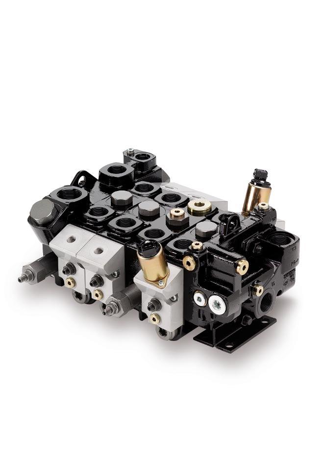
F130 Mobile Directional Control Valve
|
|
|
- George Wood
- 5 years ago
- Views:
Transcription
1 Proportional, Open or Closed Centre
2 Catalogue Description Catalogue layout This catalogue is designed to give an overview of the CF directional valve and to show how it can be customised to meet your needs exactly. Apart from general information and basic technical data therefore, the catalogue contains descriptions of the variety of options available for the different function areas of the valve. After you have studied the options and made your selection, we will tailor your valve to meet your opera ting and control criteria. Each function area is given as a subheading, followed by a brief description. When several optional functions are available for the same function area, the subheading is followed by an Item number in square brackets, e.g. Main pressure relief valve [16]. This is followed by a series of coded options, e.g. PS, PB, Y, together with a brief description of what each code represents. Alternatively, one or more pressure, flow or voltage options are given. On pages 10 and 11 are general circuit diagrams showing the basic functions of the CF valve, together with the item numbers and letter codes used to represent them. Naturally, the same item numbers and letter codes are used in all sub-circuit diagrams that appear elsewhere in the catalogue in conjunction with descriptions of the respective function areas. All sub-circuit diagrams have been extracted from the general circuit diagram. Please note that, unless stated otherwise, all sections and views of the valves have been drawn as seen from the inlet section. How to order your valve Parker has developed a computer program to specify the CF, so that the configuration of your valve can be optimised to give maximum performance in your particular hydrau lic system. Based on the demands on each individual machine function, the computer specifies the configuration of the valve to give optimal performance. It also generates complete documentation for your valve in the form of a detailed specification and hydraulic circuit diagram. The program also generates a unique product ID number that is subsequently stamped into the data plate on your valve. Your customised valve specifications remain on our database to facilitate rapid identification of your valve in the event of reordering or servicing. Early consultation with Parker saves time and money Our experienced application engineers have in-depth knowledge of the different types of hydraulic system and the ways in which they work. They are at your disposal to offer qualified advice on the various combinations of functions and control characteristics you may require, and to advise how to obtain the best possible economy. By consulting Parker early in the project planning stage, you are assured of a comprehensive hydraulic system that will give your machine the best possible operating and control characteristics, together with outstanding economy. Conversion factors 1 kg = lb 1 N = lbf 1 bar = psi 1 l = UK gallon 1 l = US gallon 1 cm 3 = in 3 1 m = feet 1 mm = in 9/5 C + 32 = F 2 Parker Hannifin
3 Contents Contents Page Valve Description...4 Constant-flow systems (CFO) (Valve with open centre, CF)...5 Constant-pressure systems, CP, CPU (Valve with closed centre, CP)...6 System Connection...7 A. Series connection, multi-valve system, CF only...7 B. Series connection, single-valve system, CF only...7 C. Parallel connection, multi-valve system...7 Technical Data...8 Environmental Characteristics...9 Hydraulic circuit diagram showing basic functions, standard valve...10 Hydraulic circuit diagram showing basic functions (model with integral spool actuators)...11 Inlet Sections [15] Main pressure relief valve [16]...14 Pressure setting [17]...14 Pump unloading [22]...14 Options in pump-unloading inlet [23]...14 Tank connection T2 [25]...15 Pump connection P2 [26]...15 Pump connection P1 [27]...15 Mid-inlet section [90]...16 Options, mid-inlet [93]...17 Main pressure relief valve [94]...17 Pressure setting [98]...17 End section [30]...18 Tank connection T1 [33]...18 Tank connection T3 [34]...19 Power-beyond function [36]...19 Reducing valve [37]...20 Pilot-oil strainer [39]...20 Separate tank connection for pilot circuit [40]...20 Spool Sections Spool actuators [50]...22 Hand-operated spool actuators with open spool end...22 Spool position indication [52]...22 Remote controlled, proportional spool actuators with open spool end...22 Remote controlled ON/OFF spool actuators with open spool end...22 Lever bracket [51]...23 Remote controlled proportional spool actuators with closed spool end...23 Spool function [60]...25 Spool designation [69]...25 Options in the spool section...25 Options in the pressure gallery [66]...25 Choice of Spool...25 Pressure limiters in service ports [76A/B](Port relief valves)...26 Port relief valve [76]...26 Function blocks (manifolds)...27 Connectors...27 Hand levers for open spool-actuators...27 Dimensional Drawings, Conventional valve...28 Dimensional Drawings, Inlet and end sections...29 Dimensional Drawings, Spool actuators...30 [00] refers to item numbers in customer specification. 3 Parker Hannifin

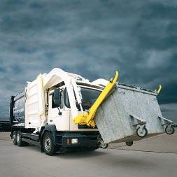
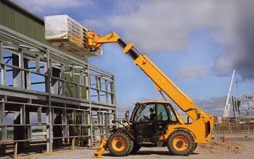
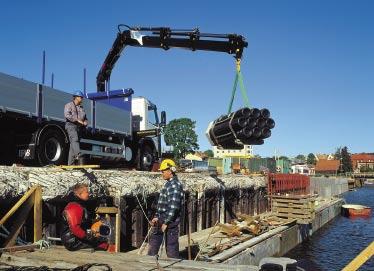
4 Valve Description The directional valve is of modular construction. Designed for many different applications, it is used in cranes and other types of construction machine, forestry machines, refuse trucks, drill rigs, etc. The comes in two versions: The CF with open centre for use with fixed pumps, and the CP with closed centre for use with variable pumps. Compact system construction The valve is of modular construction and offers unique possibilities for the integration of application-adapted functions to give compact and total system solutions for a wide range of mobile machines. Freedom in machine design The valve can be of the directly operated type, or can be equipped for electric, pneumatic or hydraulic remote control. A combination of direct and remote control is also possible. These options give the designer great freedom in terms of component location and the choice of pilot media. Economy Thanks to its modular construction, the can be optimised for both simple and complex functions. The possibility of integrating total function solutions gives low overall system costs. The valve can be modified or expanded as necessary to suit the needs of the customer. Safety The valve is of robust construction, with each function unitised. This facilitates both training and servicing and contributes greatly to safety. Moreover, the valve can be fitted with a special inlet section that enables an emergency STOP function to be incorporated into the valve to meet the demands of the EC Machinery Directive in a uniquely simple way. Design The is stackable and can be supplied in combinations of 1 to 11 spool sections, and in combination with one or more manifolds (function blocks). The valve is designed for system pressures of up to 320 bar and can be equipped with port relief valves in the service ports for a maximum pressure of 350 bar. The CF has a flow range of l/min, depending on how the valve is equipped. The CP has a flow range of l/min. There is a wide range of spools for the valve. This enables control characteristics of the valve to be customized optimally. Essential characteristics Low lever forces give comfortable operation when the valve is controlled directly. Flexible, modular construction makes it easy to modify or expand the valve to meet changing needs. Easy to change spools at any time, thanks to good manufacturing precision. Can be flanged to both standard and specially customised function manifolds. This enables even more functions to be integrated into a single unit in a compact system, with minimal piping. Mid-inlet sections enable compact system construction, even in systems with several pressure levels. Can be equipped for both multi-pump and multi-valve systems, thus increasing its range of applications in many different types of hydraulic system. Very wide range of applicationadapted spools designed to optimise control characteristics. Our proportional remote-controlled valves have pressure compensated spools, which further improves control and simultaneous-operating characteristics. Separate check valve in each spool section prevents undesirable sinking of the load. Separate port-relief valve in each service port gives individual maximum pressure limitation. The port relief valves have excellent pressure characteristics even as secondary pressure relief valves, and respond very quickly to sudden changes in load. Low pressure drops keep down energy losses and reduce the generation of heat. Machined land edges in the valve housing guarantee good control characteristics. Quality materials and high manufacturing precision ensure a superior product with low internal leakage and long service life. A wide range of optional functions enables the valve to be customised to meet your needs precisely. Open spool ends with rubber bouts increase the service life of both spools and spool seals. 4 Parker Hannifin
5 System Description B A B A M2 M3 B A Basic circuit diagram, CFO Constant-flow systems (CFO) (Valve with open centre, CF) The pump in a constant-flow system has fixed displacement, which means that the flow remains constant for a given engine speed. The pressure, however, changes to meet demand. Any oil that is not directed out to a consumer flows back to tank via the free-flow gallery (open centre) in the valve. When several lifting functions are activated simultaneously, the pressure is determined by the heaviest load. Simultaneously operated functions should therefore have roughly the same pressure needs, or be divided into separate pump circuits to minimise cross-functional interference and give good operating economy. Provided that most of the pump capacity is used, the CFO system is very economical. For this reason, it is important for the system to have a pump of the right capacity. The CFO system is the most tried and tested system for mobile machines. One of its advantages is that it contains fewer and less complex components, compared with other types of system. Control characteristics In hand-operated valves, there is no clear-cut relationship between the stroke of the lever and the speed of the load. The speed of the load will depend on its weight, the direction of force and direction of movement, by other simultaneously operated loads and by the pump flow. The reason for this is that, when more passages are opened subsequently, the flows redistribute themselves so that the pressure drop in all flow paths becomes equal. The CF s customised valve spools give considerably better simultaneous-operating characteristics. In some cases, this can result in higher energy losses during the fine-metering stage. Our directional valves intended for remote control usually have pressure compensated spools, which means that the regulated flow rate remains constant for a given lever stroke, regardless of pressure variations. q(l/min) Flow rate in service port D-spool q=80 l/min 250 bar lower 150 bar 50 bar 50 bar lift 150 bar 250 bar q pump Lever stroke in % In the CF with hand-operated spools, the speed is influenced by the size of the load, i.e. the heavier the lift load, the longer the lever stroke needed before the load starts to move, and the heavier the sink load, the quicker the lowering sequence. q(l/min) Flow rate in service port D-spool q=80 l/min 50 bar lift 250 bar 250 bar lower 50 bar q pump Lever stroke in % In the CF with PC or EC closed spool-actuators, the spools are pressure compensated. This means that the load has only a slight influence on speed. 5 Parker Hannifin
6 System Description B A B A B A P1 T2B Principle circuit diagram for valve with closed centre Constant-pressure systems, CP, CPU (Valve with closed centre, CP) The pump in a constant-pressure system has variable displacement controlled by a regulator, so that the pressure is kept constant while flow is varied to suit demand. The constantpressure system is of relatively simple construction, with an uncomplicated valve. However, the variable pump is more advanced than pumps with fixed displacement. To maintain the constant-pressure system s superior control characteristics, the pump must be dimensioned to give the sum of the maximum flows for simultaneously operated functions. If the pressure cannot be maintained, the valve loses its control characteristics quickly and actuated functions begin to influence each other, with the lightest loads receiving the most flow. The system is less sensitive to pressure drops, since a pressure corresponding to the capacity limit of the machine is always available. There are mainly two types of pumps on the market. What distinguishes them from each other is where the signal that influences the pump regulator comes from. One pump type takes the signal internally, whereas the other requires a signal from the directional valve. The CP can be used equally efficiently with either type. Control characteristics With a correctly customised CP valve, the system is given very good control characteristics and different functions do not affect each other. The system has good anti-cavitation characteristics, which means that a lowering movement can be changed to a lifting movement without delay. The maximum speed of each function is determined by the design of the spool and by the pressure demands of the load. In the CP too, remote controlled spools are pressure compensated. However, if the flow requirements of the system exceed the maximum capacity of the pump, the pressure level cannot be maintained and the normally very good control characteristics deteriorate. q(l/min) Flow rate in service port bar lower 100 bar 50 bar 50 bar lift 150 bar Lever stroke in % In the CP with hand-operated spools, all loads start moving at the same point, regardless of the size and direction of the load. The size of the load does, however, affect the slope of the curve to some extent. 6 Parker Hannifin
7 System Connection Below are a few examples of how the can be connected up. A. Series connection, multi-valve system, CF only The pump is connected to the first valve. Flow that is not directed to a consumer via the first valve continues to the next valve. The first valve therefore has priority and, in the event of full spool actuation in the first valve, no flow continues to the next valve. P1 [27] or P2 [26] Valve 1 Valve 2 Inlet section End section Inlet section Spool section T2 [25] P1 [27] or P2 [26] S [34] or ST [32] Spool section Optional tank connection End section If an additional pump is connected to valve 2, then valve 2 receives the flow from pump 2 plus any residual flow from valve 1. P1 [27] or P2 [26] P2 [26] P1 [27] T2 [25] S [34] or ST [32] Possible external check valve B. Series connection, single-valve system, CF only The pump is connected to the inlet section. Flow that is not directed out to consumers connected before the mid-inlet section continues to consumers connected after the mid-inlet section. This means that the first spool sections have priority, i.e. in the event of full spool actuation in a section before the mid-inlet section, no flow continues to the sections after the mid-inlet section. P1 [27] or P2 [26] Optional tank connection Mid-inlet section C3 [93] If an additional pump is connected to the mid-inlet section, then subsequent sections will receive the flow from pump 2 plus any flow from pump 1 that has not been used by the sections before the mid-inlet section. P1 [27] or P2 [26] Optional tank connection M3 Mid-inlet section C3 [93] C. Parallel connection, multi-valve system In parallel connection, the same pump is connected to two or more valves. The function is the same as if the pump were connected to a single large valve. L [26] P1 [27] Parallel connection, fixed pump (CFO), CF P1 [27] or P2 [26] T2 [25] S [34] or ST [32] Optional tank connection Parallel connection, variable pump (CP), CP P1 [27] P1 [27] B [26] B [26] Optional tank connection Parallel connection, variable pump (CPU), CP CUI or CUI2 [26] P1 [27] LSI [26] P1 [27] = signal line (pilot pressure) The different functions are described in more detail on pages 12, 15 and Item number in [ ] indicates part or functional area of valve. Optional tank connection Possible external pilotpressure relief valve S [34] or ST [32] Optional tank connection 7 Parker Hannifin
![Technical Data Inlet section Pump connection P1 [27] Connections in mid-inlet section, M1, M3 [90] Service port B, section 2 Spool actuator ECS3 [50] Tank connection T2 [25] External pilot connection](/docs-images/86/94718725/images/8-0.jpg "TP [40] Service port A, section 1 Tank connection T3 [34] Reduced pilot pressure PS End section [30] Spool end with hand lever attachment Tank connection T1 [33] Hand lever attachment Connection for")
8 Technical Data Inlet section Pump connection P1 [27] Connections in mid-inlet section, M1, M3 [90] Service port B, section 2 Spool actuator ECS3 [50] Tank connection T2 [25] External pilot connection TP [40] Service port A, section 1 Tank connection T3 [34] Reduced pilot pressure PS End section [30] Spool end with hand lever attachment Tank connection T1 [33] Hand lever attachment Connection for hydraulic remote control, PC [50]. Actuation pump to service port A Pressure Pump port max. 320 bar* (4640 psi) Service port max. 350 bar* (5075 psi) Tank port, static max. 10 bar (145 psi) * Stated pressures are maximum absolute shock pressures at 10 bar tank pressure. Recommended flow rates CF, pump port max. 110 l/min** (29.1 US gpm) F150CP, pump port max. 150 l/min (39.6 US gpm Return from service port max. 175 l/min (46.2 US gpm) ** Max. recommended flow rate depends on choice of spool. Internal pilot pressure Factory-set 35 bar (508 psi) Leakage from service port over spool From A or B port: max 12 cm 3 /min (0.73 cu.in/min) at pressure 100 bar (1450 psi), temperature 50 C (122 F) and viscosity 30 mm 2 /s (cst). Connections All standard connections are available in two versions unless stated otherwise: G version (BSP pipe thread) for flat seal (type Tredo) as per ISO 228/1 and UNF version for O-ring seal as per SAE J1926/1. Filtration Filtration must be arranged so that Target Contamination Class 20/18/14 according to ISO 4406 is not exceeded. For the pilot circuit, Target Contamination Class 18/16/13 according to ISO 4406 must not be exceeded. Connection Located G version UNF version P1, P2 inlet section G3/4 1-1/16-12 UN-2B T2 inlet section G1 1-5/16-12 UN-2B M1 mid-inlet section G3/4 1-1/16-12 UN-2B M3 mid-inlet section G3/4 1-1/16-12 UN-2B T1 end section G3/4 1-1/16-12 UN-2B TP, PS end section G1/4 9/16-18 UNF-2B T3 end section G3/4 1-1/16-12 UN-2B Service ports spool sections G3/4 1-1/16-12 UN-2B For other connections, please see respective sections in catalogue. Weight The weight varies somewhat with the configuration of the valve. The figures below are therefore approximate. Valve housing inclusive of spool, pressure relief valve etc; but exclusive of spool actuators. Conventional inlet (I) 4.1 kg (9.1 lb) Inlet (IU) 6.3 kg (14.0 lb) Spool section for conventional spool actuator 4.8 kg (10.7 lb) Spool section for integrated spool actuator (EC) 6.4 kg (14.2 lb) Spool section for integrated spool actuator (PC) 5.9 kg (13.1 lb) Mid-inlet section 4.1 kg (9.1 lb) End section with integrated pilot pressure supply (USP) 4.7 kg (10.4 lb) Conventional end section (US) 2.4 kg (5.3 lb) 8 Parker Hannifin
9 Environmental Characteristics The valve can be mounted in any direction. However, the mounting base should be flat and stable so that the valve is not subjected to strain. If the valve is mounted with the cap of the spool actuator facing downward, then cap A13 should be chosen for spool actuators C and B3 [50]. The valve s O-rings are normally of nitrile rubber. However, there are a number of special O-ring variants in Viton. Please contact Parker for more information. For the CP we recommend that you select A30, which gives Viton O-rings in the parting line between the sections. This is because a lot of heat can be generated in hardworking constant-pressure systems, and Viton withstands heat better than nitrile rubber. Temperature Oil temperature, working range +20 to 90 C (+68 to 194 F)* Hydraulic fluids Best performance is obtained using mineral-base oil of high quality and cleanness in the hydraulic system. Hydraulic fluids of type HLP (DIN 51524), oil for automatic gearboxes Type A and engine oil type API CD can be used. Viscosity, working range mm 2 /s** Technical information in this catalogue is applicable at an oil viscosity of 30 mm 2 /s and temperature of 50 C (122 F) using nitrile rubber seals. * Product operating limits are broadly within the above range, but satisfactory operation within the specification may not be accomplished. Leakage and response will be affected when used at temperature extremes and it is up to the user to determine acceptability at these levels. ** Performance efficiency will be reduced if outside the ideal values. These extreme conditions must be evaluated by the user to establish suitability of the products performance. Pressure drops Pressure drop with pump-unloading inlet p (bar) Pressure drop P1 to T2, 6-section valve Pressure drop with standard inlet, CF p (bar) Pressure drop P1/P2 to T q (l/min) p (bar) Pressure drop P1/P2 to service-port A/B section valve 1-section valve 6-section valve 1-section valve q (l/min) Solenoid not energized Solenoid energized p (bar) Pressure drop service-port A/B to T q (l/min) Pump unloading function. See description and hydraulic circuit diagram on page 14. With a pump-unloading inlet, the pressure drop does not fall below 5 bar, due to a counter pressure valve that guarantees the function. The pressure-drop curves P1 to T2 include an extra counter pressure of 2 bar at a flow of 100 l/min, due to a pressure drop over the check valve in the inlet. If the check valve is not chosen, the pressure drop is reduced by the corresponding value section valve 1-section valve q (l/min) 9 Parker Hannifin
10 System Description Hydraulic circuit diagram showing basic functions, standard valve Pressure gallery Tank gallery [15] [16] [76] B A [76] B A M1 M3 B A [76] P1 [27] P2 [26] T1 [33] T2 [25] [66] [50] [60] [93] [94] [36] Free-flow gallery (pump gallery) Tank gallery The circuit diagram above shows the CF with three spool sections and a mid-inlet between sections 2 and 3. The shaded areas indicate functions or function groups that are described further on in the catalogue. The item numbers in the hydraulic circuit diagram above and table below refer to function areas for which different options are available. The valve above is equipped as described below. For details of other options available, and for the CP, please refer to the respective function areas [item numbers] given alongside the various sub-headings that begin on page 12. Item No. Code Description 15 I Standard inlet section 16 PS Adjustable main pressure relief valve in inlet. 25 T2B Tank connection in inlet plugged. 26 P2B Pump connection P2 in inlet plugged. 27 P1 Pump connection P1 in inlet open. 33 T1 Tank connection T1 in end section open. 36 / Free-flow gallery connected with tank. 50 C Spring-centred spool actuator on all sections for stepless operation by hand. 60 D Spool for double-acting function in sections 1 and 3. EA Spool for single-acting function working on service port A. Service port B blocked in section 2. Item No. Code Description 66 N Load-hold check valve in each section to prevent undesirable load sinking. 76 PA Combined port-relief and anti-cavitation valve in service-ports A and B on section 1, and in serviceport A on section 3. Y2 X2 N2 Connection between service-port A and tank gallery blocked in section 2. Connection between service-port B and tank gallery open in section 2 (always the case with EA spool). Anti-cavitation valves fitted in service ports A and B of section C3 Mid-inlet with series connection to give priority to preceding sections. Intended for single or multipump operation. 94 PS Adjustable main pressure relief valve in mid-inlet. 10 Parker Hannifin
11 System Description Hydraulic circuit diagram showing basic functions (model with integral spool actuators) [22] [66] B A [76] B A B A PF PS [39] P1 [27] [37] [15] T1 [33] [16] T3B [34] T2 [25] [23] [50] [60] [40] [36] TPC [40] The circuit diagram above shows the with three electrohydraulically controlled spool sections and an integral pilot-oil supply. The shaded areas indicate functions or function groups that are described further on in the catalogue. The item numbers in the hydraulic circuit diagram above and table below refer to function areas for which different options are available. The valve above is equipped as described below. For details of other options available, and for the CP, please refer to the respective function areas [item numbers] given alongside the various sub-headings that begin overleaf. Item No. Code Description 15 IU Inlet with integrated bypass and pump-unloading function 16 PS Adjustable main pressure relief valve in inlet. 22 BEN Electric pump-unloading function. 23 N3 Check valve to prevent oil leakage. 25 T2 Tank connection in inlet open. 27 P1 Pump connection P1 in inlet open. 33 T1 Tank port T1 in end section open. 34 T3B Tank port T3 in end section plugged. 36 / Free-flow gallery connected with tank. 37 R35 Reducing valve for pilot-oil supply. 39 S Internal pilot-oil filter. 40 TPC Pilot-oil tank with check valve. 50 ECS3 Spool actuator for electric remote control. Item No. Code Description 60 D Spool for double-acting function in sections 1 and 3. EA Spool for single-acting function working on service port A. Service port B blocked in section N Load-hold check valve in each section to prevent undesirable load sinking. 76 PA Combined port-relief and anti-cavitation valve in service ports A and B of section 1 and service port A of section 3. Y2 X2 N2 Connection between service-port A and tank gallery blocked in section 2. Connection between service-port B and tank gallery open in section 2 (always the case with EA spool). Anti-cavitation valve mounted in service-ports A and B on section Parker Hannifin
![Inlet Sections Pump connection, P1 [27] Pump connection P2 [26] Tank connection, T2 [25] Main pressure relief valve [16] Standard inlet section The inlet section is available in two basic versions:](/docs-images/86/94718725/images/12-0.jpg "the conventional version and a version with pump unloading. The conventional inlet section has two pump connections, P1 and P2, and a tank connection, T2.")
12 Inlet Sections Pump connection, P1 [27] Pump connection P2 [26] Tank connection, T2 [25] Main pressure relief valve [16] Standard inlet section The inlet section is available in two basic versions: the conventional version and a version with pump unloading. The conventional inlet section has two pump connections, P1 and P2, and a tank connection, T2. The direct-acting main pressure relief valve is also located in the inlet section. The with closed centre (CP) is created by combining inlet section I with L or CUI at item [26]. The difference between the CP and the CF is that the free-flow gallery (open centre) in the CP version is used to break a hydraulic signal, instead of to convey unused pump flow to tank. P1 P2B T2B Typ av inloppssektion [15] I Standard inlet (CF + CP). IU Inlet with integrated pump-unloading function (CF). Standard inlet I without main pressure relief valve (CF). P1 P1 P2 P2 T2B T2B Standard inlet I with L-function and main pressure-relief function PS (CF). Standard inlet I with CUIfunction and main pressurerelief function PS (CP). 12 Parker Hannifin
![Inlet Sections Pump unloading solenoid BEN [22] Pump connection, P1 [27] Tank connection, T2 [25] Check valve [23] By-pass spool Counter pressure valve Main pressure relief valve [16] Inlet section](/docs-images/86/94718725/images/13-0.jpg "for valve with integrated pump-unloading function. The inlet section IU for the CF contains a pump-unloading function.")
13 Inlet Sections Pump unloading solenoid BEN [22] Pump connection, P1 [27] Tank connection, T2 [25] Check valve [23] By-pass spool Counter pressure valve Main pressure relief valve [16] Inlet section for valve with integrated pump-unloading function. The inlet section IU for the CF contains a pump-unloading function. This, together with some kind of overcentre valve, enables the machine constructor to equip the machine with an emergency-stop function. P1 Main pressure relief valve T2 Inlet section with pump unloading and main pressure relief valve. 13 Parker Hannifin
14 Technical Information Main pressure relief valve [16] The pressure relief valve is direct acting and steplessly adjustable. To give the best characteristic, the working range is divided into 7 different ranges: bar, bar, bar, bar, bar, bar and bar. The pressure can be increased to approximately 30 bar above the maximum value of the adjustment range in order to enable the machine to be tested at pressures higher than the intended maximum working pressure. The Parker PLD130 cartridge valve, which has a very good characteristic, is used as the pressure relief valve. Alternatively, a plug can be specified to block the connection pump-to-tank when the main pressure relief valve is located elsewhere in the system. PS Adjustable main pressure relief valve. Supplied factoryset. PB Y Adjustable main pressure relief valve. Supplied factoryset and sealed. Without pressure relief valve. p (bar) Pressure relief characteristic, PS/PB q (l/min) Pressure setting [17] Max. 250 bar for grey-iron version of valve. Max. 320 bar for nodular-iron version of valve. Pump unloading [22] According to the EC Machinery Directive, machines must be equipped with one or more emergency STOP functions to enable actual or impending danger to be averted. The emergency STOP function must stop the dangerous process as quickly as possible without creating additional hazards and the energy supply to the function must be cut off. The pump-unloading inlet meets these criteria by diverting incoming oil from the pump directly to the tank line, at the same time blocking the pump line into the valve. This means that no energy is transmitted to the functions. It should be noted, however, that movements driven by dead weight will continue if there are no overcentre valves. N.B. The pump-unloading function is part of the machine s safety system. The pump-unloading function can also be used to save energy when the valve is not being used. By engaging the pumpunloading function when the valve is not being used, the pumpto-tank pressure drop is reduced, see charcteristics on page 9. The solenoid BEN [22] that controls the pump-unloading function is available in 12 and 24 V versions. The solenoid is equipped with a manual actuator. For connector details, please see page 27. / Inlet not equipped with pump unloading. BEN Inlet equipped with electrically controlled pump unloading. Options in pump-unloading inlet [23] From an environmental and economic point of view, it is advantageous to close the tank gallery as well, so that no oil runs out via the anti-cavitation valve in the event of a hose rupture, for instance. To prevent this from happening, the pump-unloading inlet can be equipped with a check valve in the tank gallery. X3 Pump-unloading inlet without check valve. N3 Pump-unloading inlet with check valve in tank gallery. Overcentre valve Electric unloading valve P1 Counter pressure valve By-pass spool B A T2 Check valve Circuit diagram for pump unloading Main pressure relief valve 14 Parker Hannifin
15 Technical Information Tank connection T2 [25] T2 T2B Tank connection T2 open. Tank connection T2 plugged (normal version). Pump connection P2 [26] Only available on inlet type I [15]. See page 7 for more information about parallel connection. P2 Pump connection P2 open. P2B Pump connection P2 plugged. Normal version. L Parallel-connection used in CF when actual valve is connected downstream to another valve. The function separates the free-flow gallery from the pump gallery. (See page 12 for circuit diagram). CUI CUI2 LSI B Unloading-signal restrictor for variable pump. Via the CUI restrictor (Ø 0.8 mm), the pump pressure enters the gallery that is used as the free-flow gallery on the CF. The inlet section I [15] is connected with the pump regulator via the P1 connection. When all spools are in neutral, the flow coming from the pump gallery passes via the CUI restrictor to the tank connection in the valve s end section. The pressure that influences the pump regulator does not arise. As soon as a spool is shifted out of neutral the connection from the CUI restrictor to tank is broken and the pump pressure is again directed to the pump regulator, via the P1 connection. Unloading-signal restrictor with same function as CUI, but with Ø1.5 mm restrictor. Connection nipple that breaks the connection between the fre-flow gallery (open centre) and the pressure gallery. Used in CP in CPU system, for instance, if pump-unloading signal is created in another valve. Plug that breaks the connection between the free-flow gallery (open centre) and the pressure gallery. Used in CP when unloading signal is not wanted. Port P2 blocked. Pump connection P1 [27] P1 Pump connection P1 open. (normal version). P1B Pump connection P1 plugged. 15 Parker Hannifin
![Mid-Inlet Section Connection, M3 Connection, M1 Main pressure relief valve [94] Mid-inlet section [90] There are two connections in the mid-inlet section.](/docs-images/86/94718725/images/16-0.jpg "They can be connected in different ways, depending on the choice of options.")
16 Mid-Inlet Section Connection, M3 Connection, M1 Main pressure relief valve [94] Mid-inlet section [90] There are two connections in the mid-inlet section. They can be connected in different ways, depending on the choice of options. The main pressure relief valve (see page 17) can/or should be fitted in the mid-inlet, depending on the way in which the system is constructed. See connection alternatives overleaf. Several mid-inlets can be placed in one and the same valve to give optimum system construction. The mid-inlet section can only be selected for the CF 16 Parker Hannifin
17 Mid-Inlet Section Options, mid-inlet [93] C2 C3 C5 Mid-inlet without function. Used if you plan to convert mid-inlet to C3 or C5 later on. Mid-inlet with series connection that gives priority to upstream sections. Intended for single or multi-pump operation. Flow not used in sections upstream of the mid-inlet is added to the incoming flow in the midinlet. Mid-inlet without flow summation. Intended for multipump operation. Valve with C5 mid-inlet functions as two separate valves with a common tank connection. If an extra tank line is connected to port M1, the pump-totank pressure drop will be reduced. B A M1 M3 B A PF PS T1 T3B TPC Main pressure relief valve [94] The mid-inlet can be fitted with the same main pressure relief valve as is fitted in the standard inlet. For further information and technical data, please see Inlet section [16] on page 14. In systems in which several different pressure levels are required, main pressure relief valves can be fitted to give different pressure levels before and after the mid-inlet. PS Adjustable main pressure relief valve. Delivered with opening pressure pre-set as per specification. PB Y Adjustable main pressure relief valve. Delivered pre-set and factory-sealed. Without pressure relief valve. Mid-inlet section Mid-inlet, C3. Used in multi-pump systems and when upstream sections are to have priority over flow delivered by the pump connected to the inlet section [15] B A M1 M3 B A PF PS T1 Pressure setting [98] Max. 250 bar for grey-iron version of valve. Max. 320 bar for nodular-iron version of valve. T3B TPC Mid-inlet section Mid-inlet, C5. Used in multi-pump systems. Valve functions as two separate valves, but with common tank gallery. B A M1 M3 B A PF PS T1 T3B TPC Mid-inlet section Mid-inlet C2 Used when you want to rebuild the mid-inlet to a C3 or C5 later on. 17 Parker Hannifin
![End Sections Tank connection, T1 [33] End section viewed looking toward inlet section End section for standard valve The end section is available in two different versions: the conventional version](/docs-images/86/94718725/images/18-0.jpg "and a version with an integrated pilotpressure supply. The conventional end-section is also available, together with a spool section, as a unit called a spool section with outlet.")
18 End Sections Tank connection, T1 [33] End section viewed looking toward inlet section End section for standard valve The end section is available in two different versions: the conventional version and a version with an integrated pilotpressure supply. The conventional end-section is also available, together with a spool section, as a unit called a spool section with outlet. The conventional end-sections are equipped with a tank connection, T1. The end section for valves with integrated spool-actuators includes a reducing valve for the pilot-pressure supply, and one more tank connection, T3. A power-beyond function can be fitted in the T3 connection for serial feeding of subsequent valves (see page 7). Spool section B A Standard end-section Type of end section [30] US Standard end-section. USP End section with pilot-pressure generation. Tank connection T1 [33] T1 T1B PT ST Tank connection T1 open (normal version). Tank connection T1 plugged. Counter pressure valve that raises pressure in freeflow gallery to ensure that the minimum requisite pilotpressure is maintained (USP only). Power-beyond nipple for conventional end-section. Used to block the connection between the free-flow gallery (open centre) and tank, at the same time as the flow in the free-flow gallery is directed to a subsequent valve through the power-beyond nipple. The tank connection T2 in the inlet must be open. Compare with S at item [36]. Tank connection T1 open. Free-flow gallery connected with tank gallery in the end section. ST Tank connection T1 open. Free-flow gallery not connected with tank (series connected). ST at item [33]. 18 Parker Hannifin
![End Sections Tank connection, T3 [34] Separate tank connection for pilot oil TP [40].](/docs-images/86/94718725/images/19-0.jpg "External pilotpressure supply PS A A Plug at S [36] Reducing valve for pilot oil [37] Tank connection, T1 [33] Adapter for connection of external pilotpressure filter, YS [39] End section viewed")
![looking toward inlet section Section A-A End section with integral pilot-oil supply Tank connection T3 [34] Only on end section USP [30] T3 Tank connection T3 open.](/docs-images/86/94718725/images/19-1.jpg "T3B Tank connection T3 plugged (normal version). Power-beyond function [36] Only on end section USP [30] / Without series connection.")
19 End Sections Tank connection, T3 [34] Separate tank connection for pilot oil TP [40]. External pilotpressure supply PS A A Plug at S [36] Reducing valve for pilot oil [37] Tank connection, T1 [33] Adapter for connection of external pilotpressure filter, YS [39] End section viewed looking toward inlet section Section A-A End section with integral pilot-oil supply Tank connection T3 [34] Only on end section USP [30] T3 Tank connection T3 open. T3B Tank connection T3 plugged (normal version). Power-beyond function [36] Only on end section USP [30] / Without series connection. S Power-beyond function used to block connection between free-flow gallery and tank. Flow in free-flow gallery fed to subsequent valve through either T1 or T3 connection. Tank connection T2 in the inlet must be open. 19 Parker Hannifin
20 End Sections Reducing valve [37] Internal pilot-pressure supply is a valve function built into the end section, which acts as both a reducing valve and a pressure relief valve in the pilot circuit. For safety reasons, it is furnished with a separate safety valve function that prevents the maximum permissible reduced pressure from being exceeded. A pilot pressure for external use, e.g. for the PCL4 remotecontrol valve, can be tapped via the PS connection. / Without reducing valve R35 Reducing valve set at 35 bar. PF 35 PS Pilot-oil strainer [39] S Coarse filter with by-pass function in the internal pilotpressure supply. Filter protects pilot circuit from dirt, especially during start-up of system. YS Adaptor for connection of external pilot-pressure filter. Enables pilot circuit to be supplied with cleaner oil compared with the rest of the system. T3 Separate tank connection for pilot circuit [40] TP TPB TPC Separate tank connection for pilot circuit is open. The connection to the main tank gallery in the directional valve is blocked. This function is suitable for systems in which there is a risk of dynamic pressure variations in the tank line causing variations in the pilot circuit when there is a common tank line (recommended). End section machined for separate tank connection for pilot circuit, and plugged. Tank return of pilot circuit connected with tank gallery of directional valve. The pilot circuit s tank gallery is connected to the main tank gallery via a check valve. The check valve is used to prevent that a pressure peak reaches the spool actuators. Tank connection T3 open. Free-flow gallery connected with tank via counter pressure function, PT [33]. P red (bar) TP R P red = reduced pressure q red = take-off flow from reducing valve q red (l/min) 20 Parker Hannifin
![Spool Sections Service port B Check valve, N [66] Service port A Spool actuator [50] Spool function [60] Port relief valve, PA, port B [76] Port relief valve, PA, port A [76] Conventional spool](/docs-images/86/94718725/images/21-0.jpg "section. The is stackable and can be supplied in combinations of 1 to 11 spool sections. For each spool section, there is a wide range of spools and spool actuators to choose from.")
21 Spool Sections Service port B Check valve, N [66] Service port A Spool actuator [50] Spool function [60] Port relief valve, PA, port B [76] Port relief valve, PA, port A [76] Conventional spool section. The is stackable and can be supplied in combinations of 1 to 11 spool sections. For each spool section, there is a wide range of spools and spool actuators to choose from. This enables optimum adaptation to the application and controlled function in question. The spool sections have machined control-edges for precise regulation. For best economy, there are spool sections for one or two spools. The spool sections are connected in parallel internally. 21 Parker Hannifin
![Spool Sections Spool actuators [50] A large number of spool actuators is available for.](/docs-images/86/94718725/images/22-0.jpg "They are divided into three different groups: hand-operated, ON/OFF remote controlled and proportionally remote controlled.")

![C B3 Spool position indication [52] The type C spool actuator [50] can be equipped with an electric spool-position sensor. It has one analogue signal output to indicate the extent of spool actuation.](/docs-images/86/94718725/images/22-2.jpg "The printed circuit card and all components are protected from damp by an injected sealant. Moreover, stringent demands on EMC are met.")

. Breakaway pressure**: Final pressure**: 2.5 bar 7 bar (max.")
22 Spool Sections Spool actuators [50] A large number of spool actuators is available for. They are divided into three different groups: hand-operated, ON/OFF remote controlled and proportionally remote controlled. Hand-operated spool actuators with open spool end C B3 Spring-centred spool actuator. Actuator for stepless control with spring centring to neutral position. Three-position spool actuator. B3 is a spool actuator with mechanical three-position detent. It has three fixed positions: fully actuated at both end positions, and the neutral position. C B3 Spool position indication [52] The type C spool actuator [50] can be equipped with an electric spool-position sensor. It has one analogue signal output to indicate the extent of spool actuation. The printed circuit card and all components are protected from damp by an injected sealant. Moreover, stringent demands on EMC are met. The unit should be fed by any voltage between 9 and 32 V, in which case it gives an output voltage of 2.5 V in neutral and ± 2 V when the spool is fully actuated. / Without spool position sensor SI Spool actuator with spool position sensor SI Remote controlled, proportional spool actuators with open spool end and hand operating facility ACP Pneumatic proportional spool actuator. The ACP is a pneumatically controlled, proportional spool actuator with spring centring and the possibility of stepless control by means of a hand lever. The ACP is best controlled by the Parker VP04 remote control valve (see separate brochure). Breakaway pressure**: Final pressure**: 2.5 bar 7 bar (max. 10 bar) Connection thread: G 1/8 or NPTF 1/8-27 ACP Remote controlled ON/OFF spool actuators with open spool end and possibility of manual control ACE An electro-pneumatic ON/OFF control with spring centring and the possibility of stepless operation by means of a lever. Primary air: Control current: 4 10 bar Voltage tolerance: ± 20% 12 VDC min A 24 VDC min A The spool actuator has a common pressure gallery for primary air. The primary air can be connected to either the first or the last valve section directly by means of a plug-in connector for Ø6 mm air hose. The connector must be ordered separately, see page 27. ACE Actuation P-B, A-T Actuation P-A, B-T 22 Parker Hannifin
![Spool Sections Lever bracket [51] Leverbracket for open spool actuator is available in two different versions, LM and LJ. Leverbracket LM can t be loaded with forces sideways, from e.g.](/docs-images/86/94718725/images/23-0.jpg "a mechanical joystick. In these cases LJ should be used. The Parker standard hand levers (see page 27) can only be used with LM. Lever itself not included. Must be ordered separately (see page 27).")
 gives actuation P-B, A-T.")

 (max 35 bar) Connection thread: G 1/4 or 9/16-UNF-2B ** The breakaway pressure refers to the pressure needed for")
23 Spool Sections Lever bracket [51] Leverbracket for open spool actuator is available in two different versions, LM and LJ. Leverbracket LM can t be loaded with forces sideways, from e.g. a mechanical joystick. In these cases LJ should be used. The Parker standard hand levers (see page 27) can only be used with LM. Lever itself not included. Must be ordered separately (see page 27). LMA/ Lever bracket for open spool actuator. LJA LMB/ Lever bracket for open spool actuator. LJB LU2 No lever bracket open spool end. * Spool in ( ) gives actuation P-A, B-T. Spool out ( ) gives actuation P-B, A-T. Lever bracket LMA/LJA LMB/LJB Spool* Spool* LU2 Lever bracket Remote controlled proportional spool actuators with closed spool end Spool* PC Actuation P-B, A-T Actuation P-A, B-T PC3 PC4 Hydraulic proportional spool actuator The PC3 and PC4 are hydraulically and proportionally controlled spool actuators with spring centring. The PC3 is used on the CF with pump flows up to 80 l/min. The PC4 is used on the CF with pump flows above 80 l/min, and also on the CP. Ideally, the PC3 and PC4 should be remote-controlled by the Parker PCL4 remote control valve (see separate brochure). PC3 PC4 Breakaway pressure** 6 bar 7 bar Final pressure** 16 bar 24 bar (max 35 bar) (max 35 bar) Connection thread: G 1/4 or 9/16-UNF-2B ** The breakaway pressure refers to the pressure needed for the directional valve to open the connection pump to service port. The final pressure is the lowest pressure needed to effect full actuation of a spool in the directional valve. The foregoing data must be taken into consideration when choosing control units, since the opening pressure of the control unit must be lower than the breakaway pressure of the spool actuator in order to avoid jerky starting and stopping. However, the control unit s final pressure must be higher than the final pressure of the directional valve in order to ensure that the spools can be fully actuated. This is important for the CF because, if the spool is not actuated fully, the free-flow gallery will not close, with the result that a certain amount of flow will go directly to tank. 23 Parker Hannifin
![Spool Sections EC/ECS D101729 Actuation P-B, A-T Actuation P-A, B-T Damping restrictor [55B] Damping restrictor [55A] ECS3 ECS4 ECS3 ECS4 Electro-hydraulic proportional spool actuator The ECS3 and](/docs-images/86/94718725/images/24-0.jpg "ECS4 are electro-hydraulic, proportionally controlled spool actuators with spring centring. The ECS3 is used on the CF with pump flows up to 80 l/min.")
24 Spool Sections EC/ECS D Actuation P-B, A-T Actuation P-A, B-T Damping restrictor [55B] Damping restrictor [55A] ECS3 ECS4 ECS3 ECS4 Electro-hydraulic proportional spool actuator The ECS3 and ECS4 are electro-hydraulic, proportionally controlled spool actuators with spring centring. The ECS3 is used on the CF with pump flows up to 80 l/min. The ECS4 is used on the CF with pump flows above 80 l/min, and also on the CP. The Parker PVC25 cartridge valve is used as a pilot valve. Ideally, the ECS3 and ECS4 should be remotecontrolled by the Parker IQAN electronic remote control system (see separate brochure). The connector of AMP type must be ordered separately (see page 27). PVC25 is also available with Deutsch connector type. Voltage 12 V 24 V Breakaway current:* max 540 ma max 280 ma Final current:* min 1100 ma min 550 ma Breakaway current:* max 580 ma max 300 ma Final current:* min 1450 ma min 730 ma ECS3 Solenoid (PVC25) max 1450 ma, max 730 ma, ECS4 100% ED 100% ED Coil resistance at +20 C: 5,4 Ω 21,7 Ω Inductance: 27,7 mh 7,0 mh Tank pressure: max 15 bar max 15 bar EC3 EC4 The EC3 and EC4 spool actuators have the same data as the ECS3 and ECS4. The difference is that the solenoid valve in the EC3 and EC4 is also equipped with manual-override and air bleeding functions. * The breakaway current refers to the current needed for the directional valve to open the connection pump to service port. The final current is the lowest current needed to effect full actuation of a spool in the directional valve. This data must be taken into consideration when choosing control units, since the opening current of the control unit must be lower than the breakaway current of the spool actuator in order to avoid jerky starting and stopping. However, the control unit s final current must be higher than the final current of the directional valve in order to ensure that the spools can be fully actuated. This is important for the CF because, if the spool is not actuated fully, the free-flow gallery will not close, with the result that a certain amount of flow will go directly to tank. The stated values are guidelines only. To obtain optimum operating characteristics, the breakaway and final currents should be adjusted individually. 24 Parker Hannifin
25 Choice of Spool The spool is the most important link between the actions of the operator and the movement of the controlled function. Parker therefore goes to great lengths to optimise spools for different flows, load conditions, functions and applications. Since this is a process of continuous development work, new spools are being introduced all the time. For this reason, the many different spools available are not detailed in this catalogue. Parker s computerised specification program will generate proposals for suitable spools for the application and functions of the hydraulic system in your machine. Spool function [60] Spools are divided into different groups, depending on their basic function. D Double-acting spool. Blocked in the neutral position. EA Single-acting spool. Blocked in the neutral position and service port B blocked. EB M CA Single-acting spool. Blocked in the neutral position and service port A blocked. Double-acting spool. Service ports connected to tank (float position) in neutral. Regenerative spool for rapid feeding of a cylinder, or for flow saving. The large side of the cylinder is always connected to service port A. Certain spools have been equipped with drainage from service port to tank when the spool is in neutral. Drainage (approx. 2 mm 2 ) serves to prevent pressure build-up in the service port. Such drainage is used primarily in combination with different types of external overcentre valve. The spool designation is affected as follows: A lower-case letter is suffixed to the usual spool designation indicating function, e.g. the D-spool becomes a Da-spool to indicate drainage from service-port A to tank. a Drainage of service-port A to tank b Drainage of service-port B to tank m Drainage of service ports A and B to tank Spool designation [69] Each spool version is imprinted with an alphabetical code to facilitate identification during tuning or servicing in the field. D EA EB M CA Da Dm Pressure gallery BT A P P T Options in the spool section Options in the pressure gallery [66] The spool section s pressure gallery can be fitted with different accessories to give the best system construction. X N MS Without load-hold check valve. Load-hold check valve to prevent undesirable sinking of a heavy load while a light load is operated. Normal version. Load-hold check valve equipped with adjustment screw for restricting flow to consumer. Pressure gallery open (X) in first section, fitted with check valve (N) in second section and fitted with check valve and adjustment screw (MS) in third section. 25 Parker Hannifin
26 Spool Sections Pressure limiters in service ports [76A/B] (Port relief valves) The service ports can be equipped with individual port-relief and/or anti-cavitation valves. Parkers PLC082 cartridge valves are used as port relief valves. They are renowned for their long service life, tightness, fast opening sequence and good characteristics over the entire flow range. Port relief valve [76] X2 Y2 N2 PA Service port connected permanently with valve s tank gallery. Connection between service port and tank gallery blocked. Anti-cavitation valve fitted. The anti-cavitation valve serves to ensure that, in the event of a lower pressure in the service port than in the tank, oil can be sucked from the system oil tank to the consumer. To improve the anti-cavitation function, the oil tank can be pressurised. Note that the counter pressure valve PT [33] does not influence the pressure in the anti-cavitation valve s tank line. PLC082 combined port-relief and anti-cavitation valve fitted. Valve is factory-set at the specified pressure. Optional pressure settings: 50, 63, 80, 100, 125, 140, 160, 175, 190, 210, 230, 240, 250, 260, 280, 290, 300, 320 and 350 bar. Since the cavities for X2, Y2, N2 and PA have the same machining, it is easy to change the function of an existing valve B A In the diagram above: Section 1, service port B, is fitted with a Y2-plug (1) to block the connection to tank. Section 1, service port A, is fitted with an anti-cavitation valve N2 (2). Section 2, service port B, is equipped with a combined port-relief and anti-cavitation valve (3) to limit the pressure and prevent cavitation. Section 2, service port A, is connected to tank - X2 variant - in the case of EB spools (4). p (bar) Port-relief characteristic B A q (l/min) p (bar) Anti-cavitation characteristic q (l/min) The curve shows the pressure drop between the tank connection and service port when port relief valve (PA) or anti-cavitation valve (N) without port-relief function is used as an anticavitation valve. 26 Parker Hannifin
F130 Mobile Directional Control Valve
 Proportional, Open or Closed Centre Catalogue Description Catalogue layout This catalogue is designed to give an overview of the CF directional valve and to show how it can be customised to meet your needs
Directional Control Valve P70 Open or Closed Centre Proportional Valve Series. Catalogue HY /UK July, 2005
 Directional Control Valve Open or Closed Centre Proportional Valve Series Catalogue HY17-8546/UK July, 2005 Catalogue Information Catalogue layout This catalogue is designed to give an overview of the
Directional Control Valve P70
 Directional Control Valve Open or Closed Centre Proportional Valve Series Catalogue HY17-8546/UK January, 2007 Catalogue Information Catalogue layout This catalogue is designed to give an overview of the
Xpress L90LS Directional Control Valve. Catalog HY /UK December, 2001
 Xpress L90LS Directional Control Valve Catalog HY17-8525/UK December, 2001 Catalogue HY17-8525/UK Technical Information Xpress - general information Xpress is a valve-customization service that enables
Auxiliary valve QDS6 Sequence valve, 3-way. Catalogue (GB) (US) October 1998
 (US) October 1998") Auxiliary valve Sequence valve, 3-way Catalogue 9129 8542-02 (GB) 9129 8542-06 (US) October 1998 Sequence valve, 3-way Applications The sequence valve is designed to open or close a hydraulic pilot signal
Auxiliary valve Sequence valve, 3-way Catalogue 9129 8542-02 (GB) 9129 8542-06 (US) October 1998 Sequence valve, 3-way Applications The sequence valve is designed to open or close a hydraulic pilot signal
Directional Control Valve L90LS Proportional, Load-Sensing and Pressure Compensated. Catalogue HY /UK July, 2005
 Directional Control Valve Proportional, Load-Sensing and Pressure Compensated July, 2005 Catalogue Information Catalogue layout In addition to general information and basic technical data, this catalogue
L90LS Mobile Directional Control Valve
 Proportional, Load Sensing, Pre-compensated Catalogue Information Catalogue layout In addition to general information and basic technical data, this catalogue contains descriptions of the many optional
SDM to 8 sections monoblock valve D1WWDA02A
 SDM 1 SDM1 1 to 8 sections monoblock valve D1WWDA2A SDM1 Additional information This folder shows the product in the most standard configurations. Please contact Sales Dpt. for more detailed information
R S 280 is a modular parallel sect. Directional Control Valve RS RS In relation to its flow capacity its installation
 Directional Control Valve RS 280 3 RS 2802 3102RS28001 R S 280 is a modular parallel sect nal valve. Suitable applications are medium sized and big truck loaders, medium sized backhoe loaders and other
Leak free Pipe Rupture Valve for Excavators
 Leak free Pipe Rupture Valve for xcavators Series motion and progress Reference: 3 P 9575 1/11.6 Classification: 43.325.355...325.35 1/17 Contents Page 1 General description................................................................
Monoblock Directional Control Valve RMB 202
 Monoblock Directional Control Valve RMB 202 Key valve features RMB 202 is a 2-section mono block valve, especially designed for front-end loaders. The valve is prepared for quick connecting couplings,
Leak-Free Load-Control Valve SAE ½ psi flange
 Leak-Free Load-Control Valve SE ½ - 6000 psi flange Q max = 150 l/min [40 gpm], p max = 420 bar [6000 psi] leak-proof, two-stage hydraulic, SE-flange design 12--S... 1 Description Two-stage load-control
Proportional Pressure-Relief Cartridge Valve, Size 2...4
 Proportional Pressure-Relief Cartridge Valve, Size... Q max = l/min (6 gpm), p max = bar (58 psi) Direct acting, electrically operated Description proportional pressure-relief valves are direct acting
Inverse Prop. Pressure-Relief Cart., Size 2 4
 Inverse Prop. Pressure-Relief Cart., Size Q max = l/min (6 gpm), p max = bar (58 psi) Direct acting, electrically operated Description inverse proportional pressure-relief valves are direct acting screw-in
Inverse Proportional Pressure-Relief Cart., Size 2 4
 Inverse Proportional Pressure-Relief Cart., Size Q max = l/min, p max = 35 bar Direct acting, electrically operated Description Compact construction for cavity type AL 3/-6 UNF Operated by a proportional
PLD 03 T A CASAPPA S.p.A.
 GEAR FLOW DIVIDERS INDEX Section Page GENERAL FEATURES... 3 GENERAL DATA... 5 FLOW EQUALIZER... 6 FLOW DIVIDERS... 8 TYPICAL CIRCUITS... 10 NOTES ABOUT COMPOSITION... 12 PORTS DIMENSIONS.... 14 GROUP DIMENSIONS...
Inverse Proportional Pressure-Relief Cart., Size 2 4
 Inverse Proportional Pressure-Relief Cart., Size Q max = l/min, p max = 5 bar Direct acting, electrically operated 1 Description inverse proportional pressure-relief valves are direct acting screw-in cartridges
Inverse Proportional Pressure-Relief Cartridge, Size 10
 Inverse Proportional Pressure-Relief Cartridge, Size 1 Q max = 12 l/min, p max = 3 bar Seated pilot, spool-type main stage, damped design 1 Description inverse-proportional pressure-relief valves are size
Auxiliary Valve PRS6 Pressure Reducing Valve. Catalogue HY /UK June 2003
 Auxiliary Valve Pressure Reducing Valve June 2003 General Subject to alteration without prior notice. The curves and diagrams in this catalogue are typical examples only. While the contents of the catalogue
Proportional Pressure-Relief Cartridge Valve, Size 2...4
 Proportional Pressure-Relief Cartridge Valve, Size... Q max = l/min, p max = 3 bar Direct acting, electrically operated 1 Description proportional pressure-relief valves are direct acting screw-in cartridges
Logic Elements Screw-in Cartridge Valves Pressures to 290 bar (4200 psi) Flows to 303 l/min (80 USgpm)
 Flows to 303 l/min (80 USgpm)") Vickers artridge Valves Logic Elements Screw-in artridge Valves Pressures to 9 bar ( psi) Flows to l/min (8 USgpm) Revised 9/98 7 ontents MODEL DESRIPTION TYPIL PPLITION PRESSURE bar (psi) RTED FLOW l/min
Vickers artridge Valves Logic Elements Screw-in artridge Valves Pressures to 9 bar ( psi) Flows to l/min (8 USgpm) Revised 9/98 7 ontents MODEL DESRIPTION TYPIL PPLITION PRESSURE bar (psi) RTED FLOW l/min
directional control valve series cv691
 directional control valve series cv691 Contents Page 3 Page 4 Page 5 Page 6-7 Page 8 Page 9 Page 10 Page 11-12 General Information Technical Data Performance Curves Dimensions Relief Valve Advantages
L125 SERIES POST-COMPENSATED SECTIONAL LOAD SENSE VALVE
 L15 SERIES POST-COMPENSATED SECTIONAL LOAD SENSE VALVE TAKE CONTROL Take control with Muncie Power Products L15 directional control valve. The L15 is constructed with high-grade, iron castings and nickel-plated
Full Range Pressure Compensating Variable Flow Control
 Engineering & Manufacturing Solutions Specifications: See flow chart for capacity. Rated for 3000 psi (207 bar). Weighs 7- ¾ lbs. (3.52 kg). 30-Micron Filtration Recommended. Torque to turn side lever
Fitted with a main pressure relief valve and a load check valve on every working section.
 SDS18 1 to 12 sectional directional control valve Fitted with a main ressure relief valve and a load check valve on every working section. Available with arallel and series-arallel (tandem) circuit. Otional
Remote Control VP04 Pneumatic Proportional Remote Control Valve zrc02. Catalogue HY /UK December, 2004
 Remote Control Pneumatic Proportional Remote Control Valve zrc02 Catalogue HY17-8356/UK December, 2004 Catalogue Information Catalogue layout This catalogue has been designed to give a brief overview of
VPPL VARIABLE DISPLACEMENT AXIAL-PISTON PUMPS FOR INTERMEDIATE PRESSURE SERIES 10
 / ED VPPL VARIABLE DISPLACEMENT AXIAL-PISTON PUMPS FOR INTERMEDIATE PRESSURE SERIES OPERATING PRINCIPLE The VPPL are variable displacement axial-piston pumps with variable swash plate, suitable for applications
Load Controls Screw In Cartridge Valves Pressures to 350 bar (5000 psi) Flows to 190 l/min (50 USgpm)
 Flows to 190 l/min (50 USgpm)") Vickers Cartridge Valves Load Controls Screw In Cartridge Valves Pressures to 50 bar (5000 psi) Flows to 90 l/min (50 USgpm) Rev. 2/99 722 Contents MODEL DESCRIPTION TYP. APPLICATION PRESSURE bar (psi)
Vickers Cartridge Valves Load Controls Screw In Cartridge Valves Pressures to 50 bar (5000 psi) Flows to 90 l/min (50 USgpm) Rev. 2/99 722 Contents MODEL DESCRIPTION TYP. APPLICATION PRESSURE bar (psi)
P.C. Flow Regulator Valve Series FR101. General Description
 P.C. Flow Regulator Valve Series FR11 Compensated Flow Regulator Valve. NOTE: When used with a fixed displacement pump, pressure to the cartridge must be controlled by a relief valve located between the
4/3 Directional valve elements L85L1...(EDC-LV) with manual lever operated control with flow sharing control (LUDV concept) L85L1...
 with manual lever operated control with flow sharing control (LUDV concept) L85L1...") 4/3 Directional valve elements L8L1...(EDC-LV) with manual lever operated control with flow sharing control (LUDV concept) L8L1...(EDC-LV) RE 1831-17 Edition: 2.216 Replaces: 7.12 Size 6 Series Maximum
4/3 Directional valve elements L8L1...(EDC-LV) with manual lever operated control with flow sharing control (LUDV concept) L8L1...(EDC-LV) RE 1831-17 Edition: 2.216 Replaces: 7.12 Size 6 Series Maximum
Displacement 12, , Maximum flow rate (at 1450 rpm) bar.
 bar.") 00/07 ED PVD VARIABLE DISPLACEMENT VANE PUMPS SERIES 0 OPERATING PRINCIPLE The PVD pumps are variable displacement vane pumps with a mechanical type of pressure compensator. They allow instantaneous adjustment
00/07 ED PVD VARIABLE DISPLACEMENT VANE PUMPS SERIES 0 OPERATING PRINCIPLE The PVD pumps are variable displacement vane pumps with a mechanical type of pressure compensator. They allow instantaneous adjustment
Prop. 3-Way Pressure-Reducing Cart., Size 5 / SAE 08
 Prop. -Way Pressure-Reducing Cart., Size / SAE 8 Q max = 1 l/min (4 gpm), p max = bar (6 psi) Direct acting, electrically operated 1 Description proportional -way pressure-reducing cartridges are size
Electrically Operated Pressure-Relief Cartridge, Size 10
 Electrically Operated Pressure-Relief Cartridge, Size 1 Q max = 14 l/min (37 gpm), p max = bar (5 psi) seated pilot stage, spool-type design, with remote contral port Z Series WUVPOC-2, WUVPLC-2 1 Description
Directional Controls
 Vickers Directional Controls Directional Control Valves DG3V-3-*-60 Hydraulic Operated DG17V-3-*-60 Lever Operated DG18V-3-*-60 Air Operated DG20V-3-*-60 Cam Operated DG21V-3-*-60 Plunger Operated CETOP
1 LS unloading (control valve, orifice, none) 2 LS max pressure relief. 3 Spool type
 2 LS max pressure relief. 3 Spool type") Flow Control Valve Series LVM.. high flow rates (8 l/min) flow rates are unaffected by temperature change or when the higher load pressure alternates between the outlet ports proportional flow-sharing
Flow Control Valve Series LVM.. high flow rates (8 l/min) flow rates are unaffected by temperature change or when the higher load pressure alternates between the outlet ports proportional flow-sharing
E 328 E 498 Tank top mounting Connection up to G1½ / -24 SAE and SAE 2 Nominal flow rate up to 600 l/min / gpm
 Return-Suction Filters E 8 E 98 Tank top mounting Connection up to G½ / - SE and SE Nominal flow rate up to 6 l/min / 8. gpm Description pplication For operation in units with hydrostatic drives, when
Proportional Directional Valve System
 roportional Directional Valve System Sectional Design and Flow Sharing rinciple Reference: 31--959-EN-3 Stand: 9.216 1/2 2/2 31--959-EN-3/9.216 Contents age 1 General... 5 1.1 Description... 5 1.2 Advantages...
PILOT OPERATED PRESSURE REDUCER VALVE - Series VR4R
 PILOT OPERTED PRESSURE REDUCER VLVE - Series VR4R Veljan Pressure Reducer Valve Series VR4R are pilot operated controls used to control pressure in a secondary part of a hydraulic circuit. Pressure is
Variable Displacement Double Pump A20VO. Series 1, for open circuits Axial piston - swashplate design, Back to back - design
 Brueninghaus Hydromatik Series 1, for open circuits Axial piston - swashplate design, Back to back - design RE 93100/02.97 Sizes 60...260 Nominal Pressure up to 350 bar Peak Pressure up to 400 bar Preliminary
Auxiliary Valve QDS6 Sequence Valve, 3-way. Catalogue HY /UK June 2003
 Auxiliary Valve equence Valve, 3-way Catalogue HY17-8542/UK June 2003 General ubject to alteration without prior notice. he curves and diagrams in this catalogue are typical examples only. While the contents
Fixed Displacement Pump KFA for commercial vehicles in open circuits
 RE 91 501/05.98 Replaces: 11.96 Fixed Displacement Pump KFA for commercial vehicles in open circuits Sizes 23...107 Series 6 Nominal pressure 300 bar Peak pressure 350 bar KFA List of contents Features
INVERS. Solenoid coil 24VDC 12 VDC Exm Exd Explosion protection marking:
 direct operated INVERSE function available Q max = 2 l/min p max = bar INVERS Description EPDB The direct operated proportional pressure relief valve is built as a slip-in cartridge fitted in a connecting
PILOT OPERATED PRESSURE REDUCER VALVE - Series VR4R
 PILOT OPERTED PRESSURE REDUCER VLVE - Series VR4R Veljan Pressure Reducer Valve Series VR4R are pilot operated controls used to control pressure in a secondary part of a hydraulic circuit. Pressure is
Industrial Hydraulic Valves. Directional Control, Pressure Control, Sandwich, Subplates & Manifolds, Accessories. Catalog HY /US
 Industrial Hydraulic Valves Directional Control, Pressure Control, Sandwich, Subplates & Manifolds, Accessories Catalog HY14-2500/US Industrial Hydraulic Valves WARNING USR RSPONSIBILITY FAILUR OR IMPROPR
Proportional Throttle Cartridges, Size 16
 Proportional Throttle Cartridges, Size 16 Q max = 5 l/min, p max = 5 bar, Q N max = 14 l/min at p 1 bar Two-Stage, with Seat-Valve Shut-Off 1 Description Normally closed Seat-valve shut-off from 1 Compact
BW0500AO. ByWire Elements BW0500AO Element 4/3 with side ports IBW0500 Interface
 ywire Elements Element 4/3 with side ports IW5 Interface efore use, carefully read the GENERL INSTRUCTIONS FOR USE OF DIRECTIONL CONTROL VLVES 398SW5EN - 5--8 Technical data Nominal flow 5 l/min 3. US
Copyright, 2005 GPM Hydraulic Consulting, Inc.
 Troubleshooting and Preventive Maintenance of Hydraulic Systems Learning to Read the Signs of Future System Failures Instructed by: Al Smiley & Alan Dellinger Copyright, 2005 GPM Hydraulic Consulting,
E 328 E 498 Tank top mounting Connection up to G1½ and SAE 2 Nominal flow rate up to 600 l/min
 Return-Suction Filters E 8 E 98 Tank top mounting Connection up to G½ and SE Nominal flow rate up to 6 l/min Description pplication For operation in units with hydrostatic drives, when the return flow
E 084 Tank top mounting Connection up to G1 / -16 SAE Nominal flow rate up to 80 l/min / 21.1 gpm
 Return-Suction Filters E 08 Tank top mounting Connection up to G / -6 SE Nominal flow rate up to 80 l/min /. gpm Description pplication For operation in units with hydrostatic drives, when the return flow
Air Amplifiers & SYSTEMS
 Air Amplifiers & SYSTEMS We Accept VISA, MasterCard and American Express Air Amplifiers Point-of-Use Air Solutions Maximator air amplifiers are designed to boost plant air pressure or increase the supply
D62 - D63 Directional Control Valve l/min
 D62 - D63 Table of Contents 1 1.1 1.2 Product Description... 2 Function... 2 Properties... 2 2 Technical Data... 3 3 3.1 3.2 Ordering Information... 4 Type code... 4 Versions currently available... 4 4
Exercise 2-3. Flow Rate and Velocity EXERCISE OBJECTIVE C C C
 Exercise 2-3 EXERCISE OBJECTIVE C C C To describe the operation of a flow control valve; To establish the relationship between flow rate and velocity; To operate meter-in, meter-out, and bypass flow control
Air preparation units
 Overview Description Page Characteristics Dimensions Order instructions Type overview unit three-piece 44, 45, 48 52 6 unit two piece 44, 45, 48 52 6 Filter-regulator 44, 45, 48 53 6 Filter-water-separator
E 158 E 198 E 248. Tank top mounting Connection up to G11 / 4 Nominal flow rate up to 250 l/min e d
 R e t u r n - S u c t i o n F i l t e rs E 158 E 198 E 248 Tank top mounting Connection up to G11 / 4 Nominal flow rate up to 250 l/min 20.90-5e 0.0-2d D e s c r i p t i o n Application For operation in
Priority (Swing) Motors Data and Specifications
 Motors Data and Specifications") s Data and Specifications Specifications HMF 55 HMF 75 HMF 105 cm 3/rev in 3/rev 55 3.36 75 4.57 105 6.40 Pressure Ratings Nominal 5000 PSIG Maximum 6090 PSIG Peak 7250 PSIG Operating Speed Maximum 4100
s Data and Specifications Specifications HMF 55 HMF 75 HMF 105 cm 3/rev in 3/rev 55 3.36 75 4.57 105 6.40 Pressure Ratings Nominal 5000 PSIG Maximum 6090 PSIG Peak 7250 PSIG Operating Speed Maximum 4100
Chapter 10: Bidirectional Flow Controls
 Chapter 10: Bidirectional Flow Controls Objectives Learn about the patented, bidirectional flow control valves. Understand how the flow force affects the performance of the ZL70-36. Learn why there is
FLUID POWER FLUID POWER EQUIPMENT TUTORIAL OTHER FLUID POWER VALVES. This work covers part of outcome 2 of the Edexcel standard module:
 FLUID POWER FLUID POWER EQUIPMENT TUTORIAL OTHER FLUID POWER VALVES This work covers part of outcome 2 of the Edexcel standard module: UNIT 21746P APPLIED PNEUMATICS AND HYDRAULICS The material needed
Pressure on Demand. Air Pressure Amplifiers
 Pressure on Demand Air Pressure Amplifiers Introduction Haskel air pressure amplifiers offer the most comprehensive range in the industry combining simple principles of operation with rugged construction
Lecture 19 PRESSURE-CONTROL VALVES [CONTINUED]
![Lecture 19 PRESSURE-CONTROL VALVES [CONTINUED]](/thumbs/76/73283391.jpg "Lecture 19 PRESSURE-CONTROL VALVES [CONTINUED]") Lecture 19 PRESSURE-CONTROL VLVES [CONTINUED] 1.5 Counterbalance Valve Schematic diagram of counterbalance valve is shown in Fig. 1.14. These normally closed valves are primarily used to maintain a back
Lecture 19 PRESSURE-CONTROL VLVES [CONTINUED] 1.5 Counterbalance Valve Schematic diagram of counterbalance valve is shown in Fig. 1.14. These normally closed valves are primarily used to maintain a back
E 094 E 103 E 143 Tank top mounting Connection up to G1 / -16 SAE Nominal flow rate up to 135 l/min / 35.7 gpm
 Return Filters E 9 E E Tank top mounting Connection up to G / -6 SAE Nominal flow rate up to 5 l/min / 5.7 gpm Description Application In the return line circuits of hydraulic systems. Performance features
PTS1120TSJB PTS2120TSTSJB
 Engineering & Manufacturing Solutions Specifications: 18 gpm (68.0 lpm) Nominal Capacity. Rated up to 3000 psi (207 bar). Port Sizes: -Inlet/Outlet #12 SAE. -Work Ports #10 SAE. 10 Micron Filtration Recommended.
RE / Meter out pressure compensator Sandwich plate design Type SCA... /Series 2X. Description of function, Section 1/6. Replaces: 09.
 Meter out pressure compensator Sandwich plate design Type SCA... /Series X Sizes 6, 5 up to 35 bar up to 35 L/min RE 9 47/.96 RE 9 47/.96 Replaces: 9.87 Sandwich plate design Load compensation in lines
OIL SUPPLY SYSTEMS ABOVE 45kW OUTPUT 4.1 Oil Supply
 OIL SUPPLY SYSTEMS ABOVE 45kW OUTPUT 4.1 Oil Supply 4.1.1 General The primary function of a system for handling fuel oil is to transfer oil from the storage tank to the oil burner at specified conditions
Cover headline. Cover subheadline. Check Valves
 Check Valves Cover headline Direct and pilot operated check valve functions for applications up to 5 bar (5 psi) and 7 L/min (6 USgpm) Cover subheadline EATON Screw-In Cartridge Valves E-VLSC-MC-E December
3-Way Pressure-Reducing Cartridge, Size 2 4
 -Way Pressure-Reducing Cartridge, Size 2 Q max = 2 l/min, p max = 25 bar Spool-type design, direct acting, with manual adjustment 1 Description Compact construction for cavity type AM /- UNF to Bucher
E 212 E 222 Tank top mounting Connection up to G1¼ / -20 SAE Nominal flow rate up to 220 l/min / 58.1 gpm
 Return Filters E E Tank top mounting Connection up to G¼ / - SE up to l/min / 8. gpm Description pplication In the return line circuits of hydraulic systems. erformance features rotection against wear:
Vickers. Flow Controls. Flow Controls FN, F(C)G, FRG. Released 6/94
G, FRG. Released 6/94") Vickers Flow Controls Flow Controls FN, F(C)G, FRG Released 6/94 685 Table of Contents FN03/06/10 Model Series Application Data...............................................................................
Vickers Flow Controls Flow Controls FN, F(C)G, FRG Released 6/94 685 Table of Contents FN03/06/10 Model Series Application Data...............................................................................
PRESSURE SEQUENCE VALVE TYPE UZK
 PRESSURE SEQUENCE VALVE TYPE UZK Size 10, 20, 30 31,5 MPa up to 450 dm 3 /min WK 450 414 04. 2000r. Pressure sequence valves type UZK are used for switching a system or part of a system off when a set
Components for air preparation and pressure adjustment. OUT port position ( ) connected Rear side. of IN port. Air tank. directly.
 connected Rear side. of IN port. Air tank. directly.") Components preparation and pressure adjustment ABP Overview ABP is a component that enables boosting by s only up to twice primary pressure (.0MPa max.) in combination with using air tank but not using
Components preparation and pressure adjustment ABP Overview ABP is a component that enables boosting by s only up to twice primary pressure (.0MPa max.) in combination with using air tank but not using
LV LOADER DIRECTIONAL CONTROL VALVES INSTALLATION & USER GUIDE
 LV LOADER DIRECTIONAL CONTROL VALVES INSTALLATION & USER GUIDE SPECIFICATIONS: 10 gpm (38 lpm) Nominal Capacity. Rated up to 4000 psi (275 bar). Port Sizes-Inlet/Outlet #8SAE (3/4-16). Work Ports #8SAE
Explanations hydraulic valves TECHNICAL EXPLANATIONS HYDRAULIC VALVES. Contents. 1. Foreword. 2. Characteristic Values
 TECHNICAL EXPLANATIONS HYDRAULIC VALVES Contents 1. Foreword 2. Characteristic Values 2.1. Characteristic Values for Directional Control Valves 2.1.1. Standard Values 2.1.2. General Characteristic Values
Double Pilot Operated Cartridge Check Valve, Size 8
 Double Pilot Operated Cartridge Check Valve, Size 8 Q max = 7 l/min (19 gpm), p max = 35 bar (5 psi) pilot operated, two-stage, spring-closed cartridge-type poppet valve Compact design for cavity type
BUTTERFLY VALVES. Toll Free (877) - ICFLUID -2-
 - ICFLUID -2-") BUTTERFLY VALVES 1. General HyrdoWer is a globally recognized manufacturer of power unit accessories. They have become specialists in the design of Butterfly Valves and Hydraulic Compensators. The shut
BUTTERFLY VALVES 1. General HyrdoWer is a globally recognized manufacturer of power unit accessories. They have become specialists in the design of Butterfly Valves and Hydraulic Compensators. The shut
* Different spooltypes up to 120 l/min. in combination with simultaneously control.
 APV-16 Features. * Modular assembly system, suitable for 'Build Program'. * Max. operating pressure 420 bar. * Different spooltypes up to 120 l/min. in combination with simultaneously control. * Compact
Pressure-Relief Cartridge Valve, Size 4
 Pressure-Relief Cartridge Valve, Size 4 Q max = 30 l/min, p max = 420 bar Seated design, direct acting, with mechanical operation Compact construction for cavity type AL 3/4-16 UNF High flow rates 7 pressure
Over-center valves type LHT with oscillation damping, zero leakage
 Over-center valves type LHT with oscillation damping, zero leakage Flow rate Q max = 250 lpm Operation pressure p max = 450 bar See also: o Over-center valve type LHK acc. to D 7100 o Over-center valve
2-Port Seat Valves with Flange, PN 16
 4 45 2-Port Seat Valves with Flange, PN 6 VVF45... dular cast iron EN-GJS-400-5 valve body DN 50...50 k vs 9...00 m /h Can be equipped with SKB...- or SKC...- electrohydraulic actuators Use For use in
Function. Valve Size. Pilot Oil. p min. Bold: Designates Tier I products and options.
 Catalog HY14-255/US echnical Information ilot Operated ressure Reducing Valves Series VMY*6 General Series VMY*6 valves consist of the main stage with valve spools and the pilot stage with the proportional
Fixed Displacement Plug-In Motor A2FE
 www.phphyds.com Series 6, axial tapered piston, bent axis design for mounting in mechanical gearboxes Sizes 28...355 Nom. Pressure up to 400 bar Peak Pressure up to 450 bar he fixed displacement plug-in
PVK OPEN LOOP PUMPS. Bulletin E
 PVK OPEN LOOP PUMPS Bulletin 47025-E Table of Contents Performance Assurance page 3 Features and Benefits page 4-5 Specifications page 6 Pump Controls page 7 Table of Contents Curves Performance page 8
Circulating Lubrication Systems (Oil)
") --EN Circulating Lubrication Systems (Oil) Screw-in Restrictors, Metering Valve Distributors, low Volume Dividers Screw-in restrictor Metering valve distributor low volume divider SP/SMT (cf. leaflet -7-EN)
--EN Circulating Lubrication Systems (Oil) Screw-in Restrictors, Metering Valve Distributors, low Volume Dividers Screw-in restrictor Metering valve distributor low volume divider SP/SMT (cf. leaflet -7-EN)
Safety and Shut-off Block SAF/DSV
 1. DESCRIPTION 1.1. GENERAL The HYDAC safety and shut-off block is used to shut off and discharge hydraulic accumulators or user units. It complies with the relevant safety standards in accordance with
Fixed Displacement Motor A4FM
 Fixed Displacement Motor 4FM RE 91 12/4. replaces: 3.95 and RE 91 1 for open and closed circuits Sizes 22...5 Series 1, Series 3 Nominal pressure up to bar Peak pressure up to 45 bar Index Features 1 Ordering
ANTI SHOCK RELIEF VALVE
 ANTI SHOCK RELIEF VALVE Wheeler Road Coventry CV3 4LA England Brüsseler Allee 2 D-41812 Erkelenz Tel. +44(0)2476-217-400 Fax +44(0)2476-217-488 Tel. +49(0)24 31-80 91-0 Fax +49(0)24 31-80 91-19 www.sunhydraulics.com
BERMAD Waterworks. Level Control Valve with Altitude Pilot. 700 Series. Model X. Features and Benefits. Major Additional Features
 Level Control Valve with Altitude Pilot High level reservoirs & water towers Energy cost critical systems Systems with poor water quality Inherent refreshing Level sustaining at reservoir outlet The Level
PVQ 13 A2 R SE 1 S 20 C-11 D
 PVQ - Variable Displacement Piston Pump PVQ 13 A2 R SE 1 S 2 C-11 D 1 2 3 4 6 7 8 9 1 1 Model Series PVQ Inline Piston Pump Variable Volume Quiet Series 4 Rotation Viewed from shaft end R Right hand, standard
valves and actuators SUBSEA ACTUATION
 valves and actuators SUBSEA ACTUATION 100 C 55 M 20 Y 0 K 0 C 0 M 0 Y 80 K subsea PetrolValves offers a complete single-source integrated solution for manual or actuated high integrity ball, check, slab
PRESSURE COMPENSATORS TECNORD
 PRESSURE COMPENSATORS 2-way, Compensating / Reducing Valves GPM PSI LPM BAR MODEL CAVITY PAGE 8 3500 30 245 DF-CP2 7/8 14 UNF 60 16 3500 60 245 QC-CP2 Special 62 Typical Schematic Typical application for
Pressure reducing valve, pilot operated, Model 3DR
 RA 26 928/06.98 Pressure reducing valve, pilot operated, Model 3DR Nominal size 16 Series 5X Maximum operating pressure 3600 PSI (250 bar) Maximum flow 58.1 GPM (220 L/min) Contents Description Page Features
OP11 OVERALL SPECIFICATIONS
 The Directional Valve Series provides a compact range of manually operated directional valves for low flow applications. Because of the physical size of valves are ideally suited for mounting on small
M402LS Mobile Directional Control Valve
 Proportional, Load Sensing Conversion factors 1 kg = 2.2046 lb 1 N = 0.22481 lbf 1 bar = 14.504 psi 1 l = 0.21997 UK gallon 1 l = 0.26417 US gallon 1 cm 3 = 0.061024 in 3 1 m = 3.2808 feet 1 mm = 0.03937
3-Way Safety Block DSV
 3-Way Safety Block DSV DSV 10 - M DSV 10 - M - T-ball DSV 10 - EY 1. Description 1.1. GENERAL The 3-way safety block is used to shut off and discharge hydraulic accumulators or consumers. It complies with
Inflatable Packer Single & Double. Single & Double Packer Dimension. Wireline Packer. Water Testing Packer (WTP) Packer
 Packer") Inflatable Packer Single & Double Single & Double Packer Dimension Wireline Packer Water Testing Packer (WTP) Packer Packer Working Pressure & Depth Chart Packer Water Hand Pump Packer Air Driven Pump
Inflatable Packer Single & Double Single & Double Packer Dimension Wireline Packer Water Testing Packer (WTP) Packer Packer Working Pressure & Depth Chart Packer Water Hand Pump Packer Air Driven Pump
2-Port Seat Valves with Flange, PN 16
 4 40 2-Port Seat Valves with Flange, PN 6 VVF4... Grey cast iron EN-GJL-250 valve body DN 50...50 k vs 9...00 m /h Can be equipped with SQX- electromotoric or SKD...-, SKB...- or SKC...- electrohydraulic
MDC Series. Marine Grade 4-Way Directional Control Valve With Or Without Flow Control MDCF16TH304H MDC16TH404HB
 Engineering & Manufacturing Solutions Specifications: MDC rated for -4 gpm (-151 lpm) MDCF rated for -3 gpm (-114 lpm) Rate for 3 PSI (27 bar) Port Sizes #16 SAE (1-5/16-12) all ports Weighs 16 lbs. (7.3
SPCH/ Blowing block
 > > for linear stretch blow moulding machines > > Compact and safe design > > Best suited for PET bottles up to litres, depending on cycle time Technical features Medium: Compressed air (purity class 3..3
Directional Controls
 Vickers Directional Controls Lever Operator Directional Control Valves DG17S-8-**-10 DG17S4-10 **-50 NF D08/D10, ISO-4401-08/10 Released 5/94 681 able of Contents General Information..................................................................................
Pressure reducing valve, direct operated
 Electric Drives and Controls Table of contents Hydraulics Pressure reducing valve, direct operated Model ZDR 6 D Nominal size 6 Series 4X Maximum operating pressure 20 bar (3050 PSI) Maximum flow 50 L/min
Intrinsically safe solenoid valves on/off controls - ATEX certification
 www.atos.com Table E130-17/E Intrinsically safe solenoid valves on/off controls - ATEX certification valve body valve spool intrinsically safe solenoid electrical connector manual override DHW-0611/WP/6
Axial piston pumps type PVPY-C (-R, -L) variable displacement, with mechanical controls obsolete components - availability on request
 variable displacement, with mechanical controls obsolete components - availability on request") www.atos.com Table TA60obs/E Axial piston pumps type PVPY- (-R, -) variable displacement, with mechanical controls obsolete components - availability on request PVPY are variable displacement axial piston
www.atos.com Table TA60obs/E Axial piston pumps type PVPY- (-R, -) variable displacement, with mechanical controls obsolete components - availability on request PVPY are variable displacement axial piston