THE COLLEGE OF AERONAUTICS CRANFIELD
|
|
|
- Cory Wells
- 5 years ago
- Views:
Transcription

1 THE COLLEGE OF AERONAUTICS CRANFIELD AERODYNAMIC CHARACTERISTICS OF A 40 SWEPT BACK WING OF ASPECT RATIO 4.5 by P. S. BARNA
2 NOTE NO. 65 MAY, 1957 CRANFIELD A preliminary report on the aerodynamic characteristics of a 40 swept back wing of aspect ratio 4.5 -by- P. L 3ARNA, JVI. E. SUMMARY Experimental investigations have been made of the flow characteristics on wings of moderate sweepback. This note presents the results of the experimental investigation into the pressure distribution over a swept back wing, having an aspect ratio 4. 5 and sweep back angle 40 at quarter chord. A half model technique has been used. The wing section was R. A. E. 101 (symmetrical) with 6% maximum thickness and zero camber. Measurements of chordwise pressure distributions at a number of spanwise sections were made in the incidence range The 6 experiments were performed at Reynolds numbers of 0. 3 x 10 6 and 2x10 (based on geometric mean chord). From these measurements, lift, drag and pit ching moment characteristics of the wing were calculated. Results of the experiments for small incidences have been compared with the calculated loadings
3 obtained by methods proposed by Kucheman. ^ ' The theory predicts higher values in the spanwise load distribution at the root stations and a lift curve slope 8-12 percent lower than obtained in the experiments. Prepared under Ministry of Supply Contract No 7/Exptl/629/i-R3
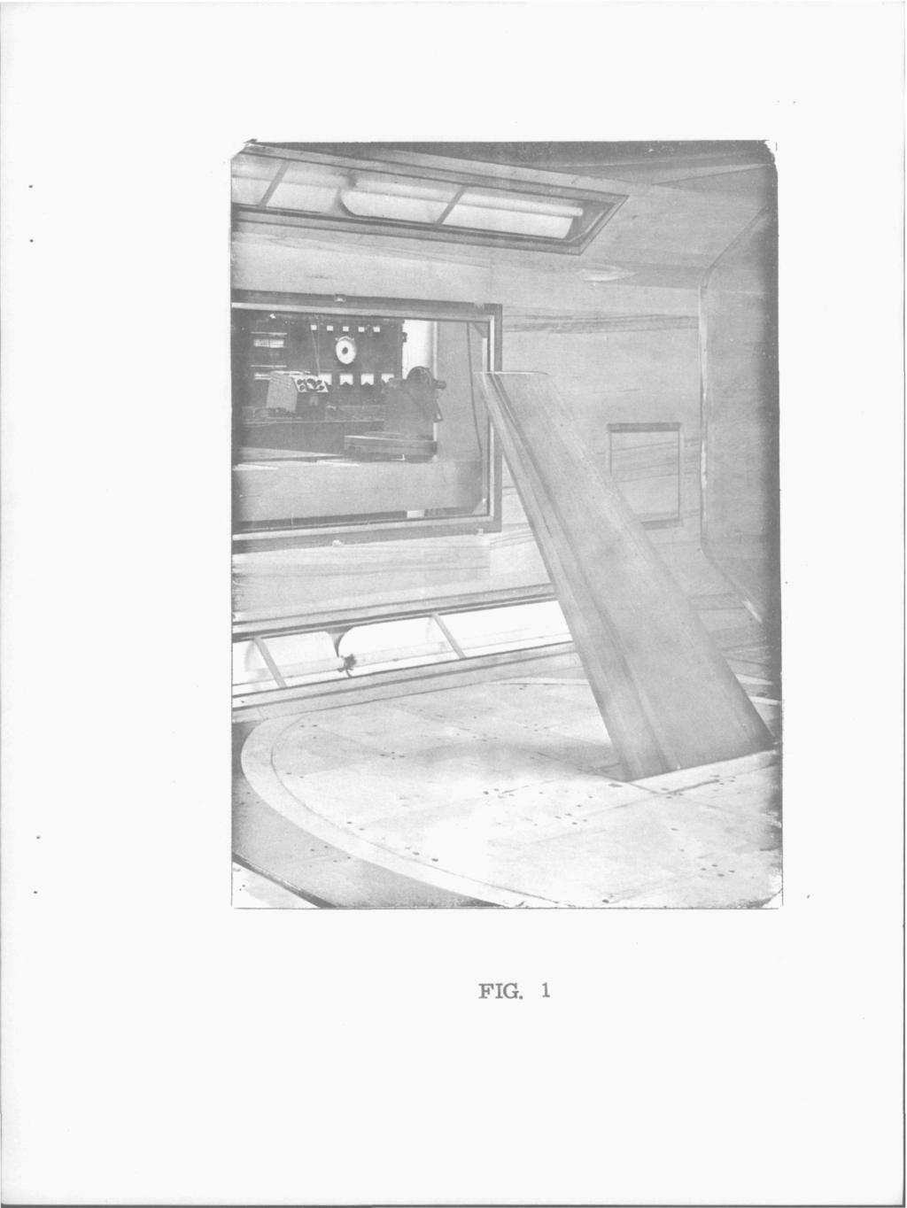
4 - 1 - TEST EQUIPxMENT The half wing was mounted in a vertical position on the turntable of the 8' x 6' low speed wind tunnel of the College of Aeronautics(Fig. 1) The tunnel floor represented the wing reflection plane. The relevant dimensions of the wing and the chordwise and the spanwise location of the pressure tappings are shown in Fig. 2. Only one side of the wing was provided with pressure tapping holes. Pressure readings were recorded at the following angles of incidence: 2, 4, 6, 7, 8, 10, 12,14,17, 20, 24,28 and 32. In order to reduce the floor boundary layer thickness in the root section of the model boundary layer suction was applied by means of a perforated plate set in the floor of the tunnel 5 ft. upstream of the centre of the turntable. The boundary layer air was returned into the tunnel at the inlet to the diffuser following the working section. An axial flow fan running at speeds up to 24, 000 r. p. m. was employed for the removal of the boundary layer. Manometers employed for the pressure measurements were the standard vertical type fitted with the standard clamping device using alcohol as indicator fluid. The air speed in the working section was obtained from the pressure difference between the settling chamber and the calibration static hole in the working section with the aid of a Betz manometer. EXPERIMENTAL PROCEDURE Preliminary tests were made to determine the effect of boundary layer suction on the wing pressure distribution. It was found that although the changes in pressure with change in boundary layer suction were small nevertheless it appeared desirable to employ suction, but that above a certain suction quantity there appeared no further improvement on the pressure distribution. As a result the tests at a Reynolds number of x 10 were with suction fan running at 24, 000 r. p. m. and the tests at a Reynolds number of 2 x 10 were performed with the suction fan running at
5 - 2 15,000 r. p. m. Since the wing was provided with tappingson one side only it was first set at an incidence + a thus providing a pressure distribution of the upper surface. The manometers having been read,the wing was set at an incidence - a thus providing a pressure distribution of the lower surface. CALIBRATION OF THE TUNNEL Prior to the experiments the tunnel v/as calibrated for flow uniformity and static pressure gradient with different boundary layer suctions, the suction fan speed varying from zero to 24, 000 r. p. m, CALCULATION OF TEST RESULTS Standard procedure was adopted for the calculatious of test results. First, at a given angle of incidence the pressure coefficients defined by C = o were plotted for each chordwise section at specified spanwise positions. Values of C were plotted both against x/c and z/c. vhere x and z were measured parallel and norm.al to the wing chord. The local lift and pressure drag values were obtained from graphical integration of the areas under the curves using the relations C, = A cos a - A sin «L 1 2 0_^ = A sin a + A cos a where C^, Cj-. = the local lift and pressure drag coefficients A = / C '^/ and A = I C dz/ 1 ƒ P o 2 J P f
6 - Ö With these values of Cj and C^^ the product C» c and Cj^c was obtained (c being the local chord) and subsequently the Cj c, Cj^c curves were plotted against spanwise location T Finally, on integration of these areas, the overall lift and pressure drag coefficients were obtained from L =- i ^L«^^ o ^D = - c 1 0,1 ƒ D ^ ^ where C = geometrical mean chord. The pitching moment coefficient of the wing about the root leading edge was obtained from c T ^ = ir f c (h) o d r? m R.L.E. ~ ^ I '^ 1 where C (h) = C (0) - c., ( ^ h being the streamwise distance between leading edge and root leading edge and Cm(o) = the pitching moment about the local wing leading edge. PRESENTATION OF TEST RESULTS The overall lift and pressure drag ooefficients plotted against geometric incidence are shown in Fig. 3, the pitching moment coefficient plotted against lift coefficient in Fig. 4, the distribution of the local lift coefficient in Fig. 5 and the local lift curve slope plotted against spanwise location in Fig. 6 The load distribution along the span is given in Fig. 7 and the spanwise position of aerodynamic centres in Fig. 8.
7 - A - BRIEF DISCUSSION OF THE TEST RESULTS. The overall lift coefficient varies linearly with incidence up to 6 approximately (Fig. 3,), the lift curve slope C, / a being This agrees fairly well with theory^ ' which gives for C^ /a. Above 6 the lift curve slope increases up to 8 then decreases with increasing incidence. Maximum lift is obtained between incidence, Cj max. being and for the high and low Reynolds number tests, respectively. Reynolds number effects over the small range of Reynolds numbers tested appear to be small up to 20 incidence, beyond this, however, the effects become noticeable. It has been shown from a surface flow investigation ' (details of which will be given in a separate report) that leading edge separation starts at approximately 6 incidence. Hence the deviation of the lift curve from a straight line is consistent with the appearance of the part span vortex. This moves inboard with increasing incidence which greatly affects the spanwise lift distribution. The local Cy max. moves inboard as shown in Fig. 5. The highest value of the local lift coefficient is approximately and may be observed at 20 incidence at the spanwise station n = Flow visualization tests indicate that a part span vortex still exists above 20. It is shown in Fig. 5 that above 20 incidence the lift gradually decreases at the root although it slightly increases towards the tip. The distributions of local lift coefficient (Fig. 5) agree fairly well for both the high and low Reynolds numbers cases except for 10 incidence. The latter disagreement may be attributed to inaccuracy of the pressure readings due to marked unsteadiness in the pressure distribution at this incidence. The pitching moment shows a fairly linear relationship with Cy up tof y = (Fig. 4) which corresponds to u = 12 which is somewhat surprising in view of the development of the
8 - 5 - part span vortex about 6 incidence. Above this incidence a stable type of stall occurs (nose down moment). The aerodynamic centre is ft. from the root leading edge as compared with the theoretical value of The variation of the local lift curve slope (Fig. 6) is in fair agreement with the theory ' ', and the difference between the the theoretical and experimental values is 8-12%. The distribution of spanwise loading (Fig. 7) in the incidence range 2-6 agrees fairly well with the theoretical curve except near the root where the theory predicts higher values than those obtained by experiment. The positions of aerodynamic centres along the span, (Fig. 8) also agree well with theory, the experimental results being somewhat lower than the theoretical values. ACKNOWLEDGEMENTS The theoretical calculations were performed by Mr P. Sharman. The lower Reynolds number tests were made by Messrs G. Appleby and E. Kendall. The tunnel was operated throughout these tests by Mr S. H. Lilley. Mrs Mc Nally assisted both in taking the readings and reducing the results. Reference. (1) A simple method of calculating the span and chordwise loading on straight and swept wings. By D. Kucheman. R. A. E. Report Aero 2476.
9 FIG. 1
10 LE, Z^^^Z^^^z 100 WING SECTION SHOWING APPROXIMATE LOCATION OF PRESSURE HOLES. WING SECTION R.A.E. loi MAX. Vc""006 at X-0-3c ASPECT RATIO 4-5 \* 0-89' ^ TAPER RATIO 0-4 '/4 c LINE SWEEPBACK 40 L.E. SWEEPBACK 43 3* FIG. 2. PLANFORM DIMENSIONS OF WING.
11 REYNOLDS NUMBER R = 2 X lo' R = 0-96 X KD* -«-» -Cm"-I.LE. MEAN dcffi VALUE -5=- =^ OF «-CL ^1-22 FIG e lo OVERALL LIFT AND PRESSURE DRAG COEFFICIENT AR=4-5 FIG 4. VARIATION OF OVERALL PITCHING MOMENT WITH OVERALL LIFT COEFFIQENT AR-4-5 m O 8 cs > c O I ^ O "n J 'T* O
12 J u CL St Ol oe 0-9 SPANWISE LOCATION V * lo REYNOLDS R-2xlO' R»0-96xlO" NUMBER ^ <r FIG. 5. DISTRIBUTION OF LOCAL LIFT COEFFICIENT CL ALONG THE SPAN. AR-4-S
13 ^,M. EXPERIMENT CORRECTED FOR TUNNEL INTERFERENCE ^-,P-^, -.4:K r ^ THEORY R - 2 X IQ* 11 tl O-2 O-4 SPANWISE LOCATION u lo EXPERIMENT CORRECTED FOR TUNNEL INTERFERENCE FIG. 6. VARIATION OF LOCAL LIFT CURVE SLOPE ALONG THE SPAN AR=4-5
14 1-4 THEORY THEORY 5 f CLC ^ V CLC = c^c o " -»«s^^ B lo 0-8 \ > 0-8 \ oi. d.. =4» V = 6 Q \ \Q 0-6 \ O-4 R = 2 X lo' R=0-96x o' \ SPANW SE LOCAT ON ^-ij/b lo '^ SPANWISE LOCATION '^='j/b/ O-B FIG. 7 SPANWISE LOAD DISTRIBUTION AR.-4-5
15 ^ac Xac.= DISTANCE OF LOCAL a.c. BEHIND LOCAL L.E. C = LOCAL REYNOLDS NUMBER R = 0-96 X lo* X CHORD. SPANWISE LOCATION V -J \ k FIG. a POSITION OF LOCAL AERODYNAMIC CENTRE ALONG SPAN.
STUDIES ON THE OPTIMUM PERFORMANCE OF TAPERED VORTEX FLAPS
 ICAS 2000 CONGRESS STUDIES ON THE OPTIMUM PERFORMANCE OF TAPERED VORTEX FLAPS Kenichi RINOIE Department of Aeronautics and Astronautics, University of Tokyo, Tokyo, 113-8656, JAPAN Keywords: vortex flap,
Aerodynamic Analysis of a Symmetric Aerofoil
 214 IJEDR Volume 2, Issue 4 ISSN: 2321-9939 Aerodynamic Analysis of a Symmetric Aerofoil Narayan U Rathod Department of Mechanical Engineering, BMS college of Engineering, Bangalore, India Abstract - The
ROAD MAP... D-1: Aerodynamics of 3-D Wings D-2: Boundary Layer and Viscous Effects D-3: XFLR (Aerodynamics Analysis Tool)
") Unit D-1: Aerodynamics of 3-D Wings Page 1 of 5 AE301 Aerodynamics I UNIT D: Applied Aerodynamics ROAD MAP... D-1: Aerodynamics of 3-D Wings D-: Boundary Layer and Viscous Effects D-3: XFLR (Aerodynamics
Unit D-1: Aerodynamics of 3-D Wings Page 1 of 5 AE301 Aerodynamics I UNIT D: Applied Aerodynamics ROAD MAP... D-1: Aerodynamics of 3-D Wings D-: Boundary Layer and Viscous Effects D-3: XFLR (Aerodynamics
Lift for a Finite Wing. all real wings are finite in span (airfoils are considered as infinite in the span)
") Lift for a Finite Wing all real wings are finite in span (airfoils are considered as infinite in the span) The lift coefficient differs from that of an airfoil because there are strong vortices produced
Lift for a Finite Wing all real wings are finite in span (airfoils are considered as infinite in the span) The lift coefficient differs from that of an airfoil because there are strong vortices produced
The effect of back spin on a table tennis ball moving in a viscous fluid.
 How can planes fly? The phenomenon of lift can be produced in an ideal (non-viscous) fluid by the addition of a free vortex (circulation) around a cylinder in a rectilinear flow stream. This is known as
Pressure distribution of rotating small wind turbine blades with winglet using wind tunnel
 Journal of Scientific SARAVANAN & Industrial et al: Research PRESSURE DISTRIBUTION OF SMALL WIND TURBINE BLADES WITH WINGLET Vol. 71, June 01, pp. 45-49 45 Pressure distribution of rotating small wind
C-1: Aerodynamics of Airfoils 1 C-2: Aerodynamics of Airfoils 2 C-3: Panel Methods C-4: Thin Airfoil Theory
 ROAD MAP... AE301 Aerodynamics I UNIT C: 2-D Airfoils C-1: Aerodynamics of Airfoils 1 C-2: Aerodynamics of Airfoils 2 C-3: Panel Methods C-4: Thin Airfoil Theory AE301 Aerodynamics I : List of Subjects
SEMI-SPAN TESTING IN WIND TUNNELS
 25 TH INTERNATIONAL CONGRESS OF THE AERONAUTICAL SCIENCES SEMI-SPAN TESTING IN WIND TUNNELS S. Eder, K. Hufnagel, C. Tropea Chair of Fluid Mechanics and Aerodynamics, Darmstadt University of Technology
Chapter 5 Wing design - selection of wing parameters - 4 Lecture 22 Topics
 Chapter 5 Wing design - selection of wing parameters - Lecture Topics 5.3.9 Ailerons 5.3.0 Other aspects of wing design Example 5. 5.3.9 Ailerons The main purpose of the ailerons is to create rolling moment
PRESSURE DISTRIBUTION OF SMALL WIND TURBINE BLADE WITH WINGLETS ON ROTATING CONDITION USING WIND TUNNEL
 International Journal of Mechanical and Production Engineering Research and Development (IJMPERD ) ISSN 2249-6890 Vol.2, Issue 2 June 2012 1-10 TJPRC Pvt. Ltd., PRESSURE DISTRIBUTION OF SMALL WIND TURBINE
HEFAT th International Conference on Heat Transfer, Fluid Mechanics and Thermodynamics July 2012 Malta
 HEFAT212 9 th International Conference on Heat Transfer, Fluid Mechanics and Thermodynamics 16 18 July 212 Malta AN EXPERIMENTAL STUDY OF SWEEP ANGLE EFFECTS ON THE TRANSITION POINT ON A 2D WING BY USING
Low Speed Wind Tunnel Wing Performance
 Low Speed Wind Tunnel Wing Performance ARO 101L Introduction to Aeronautics Section 01 Group 13 20 November 2015 Aerospace Engineering Department California Polytechnic University, Pomona Team Leader:
It should be noted that the symmetrical airfoil at zero lift has no pitching moment about the aerodynamic center because the upper and
 NAVWEPS -81-8 and high power, the dynamic pressure in the shaded area can be much greater than the free stream and this causes considerably greater lift than at zero thrust. At high power conditions the
FUSELAGE-MOUNTED FINS ON THE STATIC DIRECTIONAL STABILITY. By M. Leroy Spearman, Ross B. Robinson, and Cornelius Driver
 RESEARCH MEMORANDUM THE EFFECTS OF THE ADDITION OF SMALL FUSELAGE-MOUNTED FINS ON THE STATIC DIRECTIONAL STABILITY CHARACTERISTICS OF A MODEL OF A 45' SWEPT-WING AIRPLANE AT ANGLES OF ATTACK UP TO 15.3?
The subsonic compressibility effect is added by replacing. with
 Swept Wings The main function of a swept wing is to reduce wave drag at transonic and supersonic speeds. Consider a straight wing and a swept wing in a flow with a free-stream velocity V. Assume that the
Aircraft Design: A Systems Engineering Approach, M. Sadraey, Wiley, Figures
 Aircraft Design: A Systems Engineering Approach, M. Sadraey, Wiley, 2012 Chapter 5 Wing Design Figures 1 Identify and prioritize wing design requirements (Performance, stability, producibility, operational
High Swept-back Delta Wing Flow
 Advanced Materials Research Submitted: 2014-06-25 ISSN: 1662-8985, Vol. 1016, pp 377-382 Accepted: 2014-06-25 doi:10.4028/www.scientific.net/amr.1016.377 Online: 2014-08-28 2014 Trans Tech Publications,
THE COLLEGE OF AERONAUTICS CRANFIELD
 TEC, VL.;-:.: 'OOL DELFT AVKUNCE COA. Report No. 161 THE COLLEGE OF AERONAUTICS CRANFIELD EXPERIMENTS ON A DELTA WING USING LEADING EDGE BLOWING TO REMOVE THE SECONDARY SEPARATION by A.J. Alexander REPORT
Aerodynamic behavior of a discus
 Available online at www.sciencedirect.com Procedia Engineering 34 (2012 ) 92 97 9 th Conference of the International Sports Engineering Association (ISEA) Aerodynamic behavior of a discus Kazuya Seo a*,
EXPERIMENTAL ANALYSIS OF FLOW OVER SYMMETRICAL AEROFOIL Mayank Pawar 1, Zankhan Sonara 2 1,2
 EXPERIMENTAL ANALYSIS OF FLOW OVER SYMMETRICAL AEROFOIL Mayank Pawar 1, Zankhan Sonara 2 1,2 Assistant Professor,Chandubhai S. Patel Institute of Technology, CHARUSAT, Changa, Gujarat, India Abstract The
AF100. Subsonic Wind Tunnel AERODYNAMICS. Open-circuit subsonic wind tunnel for a wide range of investigations into aerodynamics
 Open-circuit subsonic wind tunnel for a wide range of investigations into aerodynamics Page 1 of 4 Works with Computer, chair and work table shown for photographic purposes only (not included) Screenshot
Reynolds Number Effects on Leading Edge Vortices
 Reynolds Number Effects on Leading Edge Vortices Taken From AIAA-2002-2839 Paper Reynolds Numbers Considerations for Supersonic Flight Brenda M. Kulfan 32nd AIAA Fluid Dynamics Conference and Exhibit St.
AE Dept., KFUPM. Dr. Abdullah M. Al-Garni. Fuel Economy. Emissions Maximum Speed Acceleration Directional Stability Stability.
 Aerodynamics: Introduction Aerodynamics deals with the motion of objects in air. These objects can be airplanes, missiles or road vehicles. The Table below summarizes the aspects of vehicle performance
The Effect of Canard Configurations to the Aerodynamics of the Blended Wing Body
 Vol:7, No:5, 213 The Effect of Canard Configurations to the Aerodynamics of the Blended Wing Body Zurriati Mohd Ali, Wahyu Kuntjoro, and Wirachman Wisnoe International Science Index, Aerospace and Mechanical
Chapter 5 Wing design - selection of wing parameters - 3 Lecture 21 Topics
 Chapter 5 Wing design - selection of wing parameters - 3 Lecture 21 Topics 5.3.2 Choice of sweep ( ) 5.3.3 Choice of taper ratio ( λ ) 5.3.4 Choice of twist ( ε ) 5.3.5 Wing incidence(i w ) 5.3.6 Choice
Incompressible Potential Flow. Panel Methods (3)
") Incompressible Potential Flow Panel Methods (3) Outline Some Potential Theory Derivation of the Integral Equation for the Potential Classic Panel Method Program PANEL Subsonic Airfoil Aerodynamics Issues
Incompressible Potential Flow Panel Methods (3) Outline Some Potential Theory Derivation of the Integral Equation for the Potential Classic Panel Method Program PANEL Subsonic Airfoil Aerodynamics Issues
THEORY OF WINGS AND WIND TUNNEL TESTING OF A NACA 2415 AIRFOIL. By Mehrdad Ghods
 THEORY OF WINGS AND WIND TUNNEL TESTING OF A NACA 2415 AIRFOIL By Mehrdad Ghods Technical Communication for Engineers The University of British Columbia July 23, 2001 ABSTRACT Theory of Wings and Wind
Effects of Planform Geometry and Pivot Axis Location on the Aerodynamics of Pitching Low Aspect Ratio Wings
 Fluid Dynamics and Co-located Conferences June 4-7,, San Diego, CA 4rd Fluid Dynamics Conference AIAA -99 Effects of Planform Geometry and Pivot Axis Location on the Aerodynamics of Pitching Low Aspect
Experimental and Theoretical Investigation for the Improvement of the Aerodynamic Characteristic of NACA 0012 airfoil
 International Journal of Mining, Metallurgy & Mechanical Engineering (IJMMME) Volume 2, Issue 1 (214) ISSN 232 46 (Online) Experimental and Theoretical Investigation for the Improvement of the Aerodynamic
ScienceDirect. Investigation of the aerodynamic characteristics of an aerofoil shaped fuselage UAV model
 Available online at www.sciencedirect.com ScienceDirect Procedia Engineering 90 (2014 ) 225 231 10th International Conference on Mechanical Engineering, ICME 2013 Investigation of the aerodynamic characteristics
LEADING-EDGE VORTEX FLAPS FOR SUPERSONIC TRANSPORT CONFIGURATION -EFFECTS OF FLAP CONFIGURATIONS AND ROUNDED LEADING-EDGES-
 ICAS 2002 CONGRESS LEADING-EDGE VORTEX FLAPS FOR SUPERSONIC TRANSPORT CONFIGURATION -EFFECTS OF FLAP CONFIGURATIONS AND ROUNDED LEADING-EDGES- Kenichi RINOIE*, Dong Youn KWAK**, Katsuhiro MIYATA* and Masayoshi
Wind tunnel effects on wingtip vortices
 48th AIAA Aerospace Sciences Meeting Including the New Horizons Forum and Aerospace Exposition 4-7 January 2010, Orlando, Florida AIAA 2010-325 Wind tunnel effects on wingtip vortices Xin Huang 1, Hirofumi
J. Szantyr Lecture No. 21 Aerodynamics of the lifting foils Lifting foils are important parts of many products of contemporary technology.
 J. Szantyr Lecture No. 21 Aerodynamics of the lifting foils Lifting foils are important parts of many products of contemporary technology. < Helicopters Aircraft Gliders Sails > < Keels and rudders Hydrofoils
The Influence of Battle Damage on the Aerodynamic Characteristics of a Model of an Aircraft
 Proceedings of the 26 WSEAS/IASME International Conference on Fluid Mechanics, Miami, Florida, USA, January 18-2, 26 (pp7-76) The Influence of Battle on the Aerodynamic Characteristics of a Model of an
Aerodynamic Analysis of Blended Winglet for Low Speed Aircraft
 , July 1-3, 2015, London, U.K. Aerodynamic Analysis of Blended Winglet for Low Speed Aircraft Pooja Pragati, Sudarsan Baskar Abstract This paper provides a practical design of a new concept of massive
AERODYNAMICS I LECTURE 7 SELECTED TOPICS IN THE LOW-SPEED AERODYNAMICS
 LECTURE 7 SELECTED TOPICS IN THE LOW-SPEED AERODYNAMICS The sources of a graphical material used in this lecture are: [UA] D. McLean, Understanding Aerodynamics. Arguing from the Real Physics. Wiley, 2013.
AERODYNAMIC CHARACTERISTICS OF NACA 0012 AIRFOIL SECTION AT DIFFERENT ANGLES OF ATTACK
 AERODYNAMIC CHARACTERISTICS OF NACA 0012 AIRFOIL SECTION AT DIFFERENT ANGLES OF ATTACK SUPREETH NARASIMHAMURTHY GRADUATE STUDENT 1327291 Table of Contents 1) Introduction...1 2) Methodology.3 3) Results...5
OUTLINE FOR Chapter 4
 16/8/3 OUTLINE FOR Chapter AIRFOIL NOMENCLATURE The leaing ege circle: (usually raius =. chor length c) The trailing ege: The chor line: Straight line connecting the center of leaing ege circle an the
AERODYNAMIC CHARACTERISTICS OF SPIN PHENOMENON FOR DELTA WING
 ICAS 2002 CONGRESS AERODYNAMIC CHARACTERISTICS OF SPIN PHENOMENON FOR DELTA WING Yoshiaki NAKAMURA (nakamura@nuae.nagoya-u.ac.jp) Takafumi YAMADA (yamada@nuae.nagoya-u.ac.jp) Department of Aerospace Engineering,
Design and Development of Micro Aerial Vehicle
 Advances in Aerospace Science and Applications. ISSN 2277-3223 Volume 4, Number 1 (2014), pp. 91-98 Research India Publications http://www.ripublication.com/aasa.htm Design and Development of Micro Aerial
Experimental Investigation of End Plate Effects on the Vertical Axis Wind Turbine Airfoil Blade
 Experimental Investigation of End Plate Effects on the Vertical Axis Wind Turbine Airfoil Blade Rikhi Ramkissoon 1, Krishpersad Manohar 2 Ph.D. Candidate, Department of Mechanical and Manufacturing Engineering,
IMPACT OF FUSELAGE CROSS SECTION ON THE STABILITY OF A GENERIC FIGHTER
 IMPACT OF FUSELAGE CROSS SECTION ON THE STABILITY OF A GENERIC FIGHTER Robert M. Hall NASA Langley Research Center Hampton, Virginia ABSTRACT Many traditional data bases, which involved smooth-sided forebodies,
AE2610 Introduction to Experimental Methods in Aerospace AERODYNAMIC FORCES ON A WING IN A SUBSONIC WIND TUNNEL
 AE2610 Introduction to Experimental Methods in Aerospace AERODYNAMIC FORCES ON A WING IN A SUBSONIC WIND TUNNEL Objectives The primary objective of this experiment is to familiarize the student with measurement
Preliminary design of a high-altitude kite. A flexible membrane kite section at various wind speeds
 Preliminary design of a high-altitude kite A flexible membrane kite section at various wind speeds This is the third paper in a series that began with one titled A flexible membrane kite section at high
Welcome to Aerospace Engineering
 Welcome to Aerospace Engineering DESIGN-CENTERED INTRODUCTION TO AEROSPACE ENGINEERING Notes 4 Topics 1. Course Organization 2. Today's Dreams in Various Speed Ranges 3. Designing a Flight Vehicle: Route
BUILD AND TEST A WIND TUNNEL
 LAUNCHING INTO AVIATION 9 2018 Aircraft Owners and Pilots Association. All Rights Reserved. UNIT 2 SECTION D LESSON 2 PRESENTATION BUILD AND TEST A WIND TUNNEL LEARNING OBJECTIVES By the end of this lesson,
A COMPUTATIONAL STUDY ON THE DESIGN OF AIRFOILS FOR A FIXED WING MAV AND THE AERODYNAMIC CHARACTERISTIC OF THE VEHICLE
 28 TH INTERNATIONAL CONGRESS OF THE AERONAUTICAL SCIENCES A COMPUTATIONAL STUDY ON THE DESIGN OF AIRFOILS FOR A FIXED WING MAV AND THE AERODYNAMIC CHARACTERISTIC OF THE VEHICLE Jung-Hyun Kim*, Kyu-Hong
EXAMPLE MICROLIGHT AIRCRAFT LOADING CALCULATIONS
 1. Introduction This example loads report is intended to be read in conjunction with BCAR Section S and CS-VLA both of which can be downloaded from the LAA webpage, and the excellent book Light Aircraft
Tim Lee s journal publications
 Tim Lee s journal publications 82. Lee, T., and Tremblay-Dionne, V., (2018) Impact of wavelength and amplitude of a wavy ground on a static NACA 0012 airfoil submitted to Journal of Aircraft (paper in
Jet Propulsion. Lecture-17. Ujjwal K Saha, Ph. D. Department of Mechanical Engineering Indian Institute of Technology Guwahati
 Lecture-17 Prepared under QIP-CD Cell Project Jet Propulsion Ujjwal K Saha, Ph. D. Department of Mechanical Engineering Indian Institute of Technology Guwahati 1 Lift: is used to support the weight of
Reduction of Skin Friction Drag in Wings by Employing Riblets
 Reduction of Skin Friction Drag in Wings by Employing Riblets Kousik Kumaar. R 1 Assistant Professor Department of Aeronautical Engineering Nehru Institute of Engineering and Technology Coimbatore, India
JOURNAL PUBLICATIONS
 1 JOURNAL PUBLICATIONS 71. Lee, T., Mageed, A., Siddiqui, B. and Ko, L.S., (2016) Impact of ground proximity on aerodynamic properties of an unsteady NACA 0012 airfoil, submitted to Journal of Aerospace
Aerofoil Design for Man Powered Aircraft
 Man Powered Aircraft Group Aerofoil Design for Man Powered Aircraft By F. X. Wortmann Universitat Stuttgart From the Second Man Powered Aircraft Group Symposium Man Powered Flight The Way Ahead 7 th February
Influence of wing span on the aerodynamics of wings in ground effect
 Influence of wing span on the aerodynamics of wings in ground effect Sammy Diasinos 1, Tracie J Barber 2 and Graham Doig 2 Abstract A computational fluid dynamics study of the influence of wing span has
INTERFERENCE EFFECT AND FLOW PATTERN OF FOUR BIPLANE CONFIGURATIONS USING NACA 0024 PROFILE
 Proceedings of the International Conference on Mechanical Engineering 211 (ICME211) 18-2 December 211, Dhaka, Bangladesh ICME11-FL-1 INTERFERENCE EFFECT AND FLOW PATTERN OF FOUR BIPLANE CONFIGURATIONS
EXPERIMENTAL ANALYSIS OF THE CONFLUENT BOUNDARY LAYER BETWEEN A FLAP AND A MAIN ELEMENT WITH SAW-TOOTHED TRAILING EDGE
 24 TH INTERNATIONAL CONGRESS OF THE AERONAUTICAL SCIENCES EXPERIMENTAL ANALYSIS OF THE CONFLUENT BOUNDARY LAYER BETWEEN A FLAP AND A MAIN ELEMENT WITH SAW-TOOTHED TRAILING EDGE Lemes, Rodrigo Cristian,
Subsonic Wind Tunnel 300 mm
 aerodynamics AF1300 An open circuit suction subsonic wind tunnel with a working section of 300 mm by 300 mm and 600 mm long Screenshot of the optional VDAS software Saves time and money compared to full-scale
Incompressible Flow over Airfoils
 Road map for Chap. 4 Incompressible Flow over Airfoils Aerodynamics 2015 fall - 1 - < 4.1 Introduction > Incompressible Flow over Airfoils Incompressible flow over airfoils Prandtl (20C 초 ) Airfoil (2D)
AF101 to AF109. Subsonic Wind Tunnel Models AERODYNAMICS. A selection of optional models for use with TecQuipment s Subsonic Wind Tunnel (AF100)
") Page 1 of 4 A selection of optional models for use with TecQuipment s Subsonic Wind Tunnel (AF100) Dimpled Sphere Drag Model (from AF109) shown inside the TecQuipment AF100 Wind Tunnel. Cylinder, aerofoils,
Page 1 of 4 A selection of optional models for use with TecQuipment s Subsonic Wind Tunnel (AF100) Dimpled Sphere Drag Model (from AF109) shown inside the TecQuipment AF100 Wind Tunnel. Cylinder, aerofoils,
SUBPART C - STRUCTURE
 SUBPART C - STRUCTURE GENERAL CS 23.301 Loads (a) Strength requirements are specified in terms of limit loads (the maximum loads to be expected in service) and ultimate loads (limit loads multiplied by
Measurement of Pressure. The aerofoil shape used in wing is to. Distribution and Lift for an Aerofoil. generate lift due to the difference
 Measurement of Pressure Distribution and Lift for an Aerofoil. Objective The objective of this experiment is to investigate the pressure distribution around the surface of aerofoil NACA 4415 and to determine
Aerodynamic Forces on a Wing in a Subsonic Wind Tunnel. Learning Objectives
 Aerodynamic Forces on a Wing in a Subsonic Wind Tunnel AerodynamicForces Lab -1 Learning Objectives 1. Familiarization with aerodynamic forces 2. Introduction to airfoil/wing basics 3. Use and operation
Wind Tunnel Tests of Wind Turbine Airfoils at High Reynolds Numbers
 Journal of Physics: Conference Series OPEN ACCESS Wind Tunnel Tests of Wind Turbine Airfoils at High Reynolds Numbers To cite this article: E Llorente et al 014 J. Phys.: Conf. Ser. 54 0101 View the article
COMPUTER-AIDED DESIGN AND PERFORMANCE ANALYSIS OF HAWT BLADES
 5 th International Advanced Technologies Symposium (IATS 09), May 13-15, 2009, Karabuk, Turkey COMPUTER-AIDED DESIGN AND PERFORMANCE ANALYSIS OF HAWT BLADES Emrah KULUNK a, * and Nadir YILMAZ b a, * New
COMPUTATIONAL FLUID DYNAMIC ANALYSIS OF AIRFOIL NACA0015
 International Journal of Mechanical Engineering and Technology (IJMET) Volume 8, Issue 2, February 2017, pp. 210 219 Article ID: IJMET_08_02_026 Available online at http://www.iaeme.com/ijmet/issues.asp?jtype=ijmet&vtype=8&itype=2
CFD Study of Solid Wind Tunnel Wall Effects on Wing Characteristics
 Indian Journal of Science and Technology, Vol 9(45), DOI :10.17485/ijst/2016/v9i45/104585, December 2016 ISSN (Print) : 0974-6846 ISSN (Online) : 0974-5645 CFD Study of Solid Wind Tunnel Wall Effects on
Induced Drag Reduction for Modern Aircraft without Increasing the Span of the Wing by Using Winglet
 International Journal of Mechanical & Mechatronics Engineering IJMME-IJENS Vol:10 No:03 49 Induced Drag Reduction for Modern Aircraft without Increasing the Span of the Wing by Using Winglet Mohammad Ilias
Long Win s Educational Facilities for Fluid Mechanics
 Since 1985 F luid mechanics is a science to study how fluids flow and how fluids act on objects. T he wind tunnel is a comprehensive, complete and substantial system for students to study fundamental and
The Aerodynamic Drag of Parafoils
 The Aerodynamic Drag of Parafoils A. C. Carruthers and A. Filippone The University of Manchester Manchester M60 1QD United Kingdom Introduction The parafoil is an aerodynamic decelerator that uses the
RESEARCH MEMORANDUM. WASHINGTON December 3, AERODYNl$MIC CHARACTERISTICS OF A MODEL? OF AN ESCAPE ...,
 .". -.%. ;& RESEARCH MEMORANDUM AERODYNl$MIC CHARACTERISTICS OF A MODEL? OF AN ESCAPE 1 \ < :. By John G. Presnell, Jr. w'..., '.., 3... This material contains information affecting the National Bfense
Aerodynamics of a Swept Wing with Ice Accretion at Low Reynolds Number
 30th AIAA Applied Aerodynamics Conference 25-28 June 2012, New Orleans, Louisiana AIAA 2012-2795 Aerodynamics of a Swept Wing with Ice Accretion at Low Reynolds Number Jeff M. Diebold *, Marianne C. Monastero
Preliminary Analysis of Drag Reduction for The Boeing
 Preliminary Analysis of Drag Reduction for The Boeing 747-400 By: Chuck Dixon, Chief Scientist, Vortex Control Technologies LLC 07. 31. 2012 Potential for Airflow Separation That Can Be Reduced By Vortex
Subsonic wind tunnel models
 aerodynamics AF1300a to AF1300l A selection of optional models for use with TecQuipment s Subsonic Wind Tunnel (AF1300) Dimpled Sphere Drag Model (from AF1300j) shown inside the TecQuipment AF1300 Wind
WIND-INDUCED LOADS OVER DOUBLE CANTILEVER BRIDGES UNDER CONSTRUCTION
 WIND-INDUCED LOADS OVER DOUBLE CANTILEVER BRIDGES UNDER CONSTRUCTION S. Pindado, J. Meseguer, J. M. Perales, A. Sanz-Andres and A. Martinez Key words: Wind loads, bridge construction, yawing moment. Abstract.
Aerodynamic Simulation of Runback Ice Accretion
 1st AIAA Atmospheric and Space Environments Conference 22-25 June 2009, San Antonio, Texas AIAA 2009-4261 Aerodynamic Simulation of Runback Ice Accretion Andy P. Broeren NASA Glenn Research Center, Cleveland,
Study of a Swept Wing with Leading-Edge Ice Using a Wake Survey Technique
 51st AIAA Aerospace Sciences Meeting including the New Horizons Forum and Aerospace Exposition 7-1 January 213, Grapevine (Dallas/Ft. Worth Region), Texas AIAA 213-245 Study of a Swept Wing with Leading-Edge
Flow and Heat Transfer Characteristics Over a NACA0018 Aerofoil and a Test Aerofoil A Comparative Study
 Flow and Heat Transfer Characteristics Over a NACA0018 Aerofoil and a Test Aerofoil A Comparative Study 1 M.Sri Rama Murthy, 2 Dr. K.Rambabu, 3 Dr. A.V.S.S.K.S.Gupta 1,2 Dept. of ME, Sir C.R.R.College
Improved Aerodynamic Characteristics of Aerofoil Shaped Fuselage than that of the Conventional Cylindrical Shaped Fuselage
 International Journal of Scientific & Engineering Research Volume 4, Issue 1, January-213 1 Improved Aerodynamic Characteristics of Aerofoil Shaped Fuselage than that of the Conventional Cylindrical Shaped
COMPUTATIONAL FLOW MODEL OF WESTFALL'S LEADING TAB FLOW CONDITIONER AGM-09-R-08 Rev. B. By Kimbal A. Hall, PE
 COMPUTATIONAL FLOW MODEL OF WESTFALL'S LEADING TAB FLOW CONDITIONER AGM-09-R-08 Rev. B By Kimbal A. Hall, PE Submitted to: WESTFALL MANUFACTURING COMPANY September 2009 ALDEN RESEARCH LABORATORY, INC.
THEORETICAL EVALUATION OF FLOW THROUGH CENTRIFUGAL COMPRESSOR STAGE
 THEORETICAL EVALUATION OF FLOW THROUGH CENTRIFUGAL COMPRESSOR STAGE S.Ramamurthy 1, R.Rajendran 1, R. S. Dileep Kumar 2 1 Scientist, Propulsion Division, National Aerospace Laboratories, Bangalore-560017,ramamurthy_srm@yahoo.com
NUMERICAL INVESTIGATION OF THE FLOW BEHAVIOUR IN A MODERN TRAFFIC TUNNEL IN CASE OF FIRE INCIDENT
 - 277 - NUMERICAL INVESTIGATION OF THE FLOW BEHAVIOUR IN A MODERN TRAFFIC TUNNEL IN CASE OF FIRE INCIDENT Iseler J., Heiser W. EAS GmbH, Karlsruhe, Germany ABSTRACT A numerical study of the flow behaviour
SOARING AND GLIDING FLIGHT OF THE BLACK VULTURE
 [ 280 ] SOARING AND GLIDING FLIGHT OF THE BLACK VULTURE BY B. G. NEWMAN* Department of Engineering, University of Cambridge {Received 10 September 1957) INTRODUCTION In 1950 Raspet published an interesting
ANALYSIS OF AERODYNAMIC CHARACTERISTICS OF A SUPERCRITICAL AIRFOIL FOR LOW SPEED AIRCRAFT
 ANALYSIS OF AERODYNAMIC CHARACTERISTICS OF A SUPERCRITICAL AIRFOIL FOR LOW SPEED AIRCRAFT P.Sethunathan 1, M.Niventhran 2, V.Siva 2, R.Sadhan Kumar 2 1 Asst.Professor, Department of Aeronautical Engineering,
Investigation on 3-D Wing of commercial Aeroplane with Aerofoil NACA 2415 Using CFD Fluent
 Investigation on 3-D of commercial Aeroplane with Aerofoil NACA 2415 Using CFD Fluent Rohit Jain 1, Mr. Sandeep Jain 2, Mr. Lokesh Bajpai 3 1PG Student, 2 Associate Professor, 3 Professor & Head 1 2 3
AN EXPERIMENTAL STUDY OF THE EFFECTS OF SWEPT ANGLE ON THE BOUNDARY LAYER OF THE 2D WING
 AN EXPERIMENTAL STUDY OF THE EFFECTS OF SWEPT ANGLE ON THE BOUNDARY LAYER OF THE 2D WING A. Davari *, M.R. Soltani, A.Tabrizian, M.Masdari * Assistant Professor, Department of mechanics and Aerospace Engineering,
RESEARCH MEMORANDUM FOR AERONAUTICS HAVING A TRZANGULAR WING OF ASPECT WETI0 3. Moffett Field, Calif. WASHINGTON. Ames Aeronautical Laboratory
 RESEARCH MEMORANDUM THE EFFECTS OF TRAILINGEDGE FLAPS ON THE SUBSONIC AERODYNAMIC CHARACTERISTICS OF AN AIRPLANE MODEL HAVING A TRZANGULAR WING OF ASPECT WETI0 3 By Bruce E. Tinling and A. V. I I Ames
Aerodynamic Analyses of Horizontal Axis Wind Turbine By Different Blade Airfoil Using Computer Program
 ISSN : 2250-3021 Aerodynamic Analyses of Horizontal Axis Wind Turbine By Different Blade Airfoil Using Computer Program ARVIND SINGH RATHORE 1, SIRAJ AHMED 2 1 (Department of Mechanical Engineering Maulana
Preliminary Design Review (PDR) Aerodynamics #2 AAE-451 Aircraft Design
 Aerodynamics #2 AAE-451 Aircraft Design") Preliminary Design Review (PDR) Aerodynamics #2 AAE-451 Aircraft Design Aircraft Geometry (highlight any significant revisions since Aerodynamics PDR #1) Airfoil section for wing, vertical and horizontal
Preliminary Design Review (PDR) Aerodynamics #2 AAE-451 Aircraft Design Aircraft Geometry (highlight any significant revisions since Aerodynamics PDR #1) Airfoil section for wing, vertical and horizontal
No Description Direction Source 1. Thrust
 AERODYNAMICS FORCES 1. WORKING TOGETHER Actually Lift Force is not the only force working on the aircraft, during aircraft moving through the air. There are several aerodynamics forces working together
DESIGN OF AN AERODYNAMIC MEASUREMENT SYSTEM FOR UNMANNED AERIAL VEHICLE AIRFOILS
 DESIGN OF AN AERODYNAMIC MEASUREMENT SYSTEM FOR UNMANNED AERIAL VEHICLE AIRFOILS L. Velázquez-Araque 1 and J. Nožička 1 1 Department of Fluid Dynamics and Power Engineering, Faculty of Mechanical Engineering
CFD ANALYSIS OF FLOW AROUND AEROFOIL FOR DIFFERENT ANGLE OF ATTACKS
 www.mechieprojects.com CFD ANALYSIS OF FLOW AROUND AEROFOIL FOR DIFFERENT ANGLE OF ATTACKS PRESENTATION OUTLINE AIM INTRODUCTION LITERATURE SURVEY CFD ANALYSIS OF AEROFOIL RESULTS CONCLUSIONS www.mechieprojects.com
Flow Field Investigation of Flat Bottom Aerofoil under Ground Effect
 IOSR Journal of Mechanical and Civil Engineering (IOSR-JMCE) e-issn: 2278-1684,p-ISSN: 2320-334X, Volume 12, Issue 4 Ver. VI (Jul. - Aug. 2015), PP 83-88 www.iosrjournals.org Flow Field Investigation of
Subsonic Wind Tunnel 300 mm
 aerodynamics AF1300 TecQuipment s AF1300 Subsonic Wind Tunnel. See also AF300S starter set that includes AF1300Z Basic Lift and Drag Balance and a set of AF1300J Three Dimensional Drag Models with the
Aero Club. Introduction to Flight
 Aero Club Presents Introduction to RC Modeling Module 1 Introduction to Flight Centre For Innovation IIT Madras Page2 Table of Contents Introduction:... 3 How planes fly How is lift generated?... 3 Forces
Aerodynamic investigation of Winglets on Wind Turbine Blades using CFD
 Risø-R-1543(EN) Aerodynamic investigation of Winglets on Wind Turbine Blades using CFD Jeppe Johansen and Niels N. Sørensen Risø National Laboratory Roskilde Denmark February 26 Author: Jeppe Johansen
FLOW QUALITY IMPROVEMENT IN A TRANSONIC WIND TUNNEL
 HEFAT2012 9 th International Conference on Heat Transfer, Fluid echanics and Thermodynamics 16 18 July 2012 alta FLOW QUALITY IPROVEENT IN A TRANSONIC WIND TUNNEL Amiri K.* and Soltani.R. Department of
CFD AND EXPERIMENTAL STUDY OF AERODYNAMIC DEGRADATION OF ICED AIRFOILS
 Colloquium FLUID DYNAMICS 2008 Institute of Thermomechanics AS CR, v.v.i., Prague, October 22-24, 2008 p.1 CFD AND EXPERIMENTAL STUDY OF AERODYNAMIC DEGRADATION OF ICED AIRFOILS Vladimír Horák 1, Dalibor
Abstract. 1 Introduction
 Developments in modelling ship rudder-propeller interaction A.F. Molland & S.R. Turnock Department of Ship Science, University of Southampton, Highfield, Southampton, S017 IBJ, Hampshire, UK Abstract A
Avai 193 Fall 2016 Laboratory Greensheet
 Avai 193 Fall 2016 Laboratory Greensheet Lab Report 1 Title: Instrumentation Test Technique Research Process: Break into groups of 4 people. These groups will be the same for all of the experiments performed
FABRICATION OF VERTICAL AXIS WIND TURBINE WITH WIND REDUCER AND EXPERIMENTAL INVESTIGATIONS
 87 CHAPTER-4 FABRICATION OF VERTICAL AXIS WIND TURBINE WITH WIND REDUCER AND EXPERIMENTAL INVESTIGATIONS 88 CHAPTER-4 FABRICATION OF VERTICAL AXIS WIND TURBINE WITH WIND REDUCER AND EXPERIMENTAL INVESTIGATIONS