Formula SAE Aerodynamic Package Design
|
|
|
- Joel Grant
- 6 years ago
- Views:
Transcription
1 Formula SAE Aerodynamic Package Design Phase III Report December 5, 2016 Justin Hansen Austin Ma Gordon Miller Garrett Schultz Sharegh Yusefi
2 i Ave NW Edmonton, Alberta T6G 2C6 (780) December 5, 2016 Mr. Chris Taschuk Formula SAE Team Lead of Aerodynamics University of Alberta Edmonton AB T6G-2R3 RE: Formula SAE Aerodynamic Package (Proposal 14) Dear Mr. Taschuk, Triple G Engineering is pleased to present the results of the final phase for the Formula SAE Aerodynamic Package. The enclosed contains the following items: Design refinements made in Phase III and an updated compliance matrix Engineering analysis and performance of the aerodynamic package Cost analysis and a finalized project schedule Detailed drawing package for the final design The final aerodynamic package was able to meet most of the specifications requested by the Formula SAE team. This included a 10% increase in downforce, improvement in the lift to drag ratio, and a center of pressure located in front of the center of mass. A total of 646 engineering hours was spent on the project which correspond to a total cost of $60,525. Total material and manufacturing cost for the aerodynamic package was estimated to be $1,770. Triple G Engineering would like to thank you and the Formula SAE team for giving us the opportunity to create the aerodynamic package for the 2017 FSAE vehicle. We look forward to your evaluation of our design. If you have any questions please direct them to gmmiller@ualberta.ca. Sincerely, Gordon Miller Encl. cc. Carlos F. Lange, U of A Michael Lipsett, U of A
3 ii EXECUTIVE SUMMARY Triple G Engineering was contracted by the University of Alberta FSAE student group to create a design for the aerodynamic components for the 2017 Formula SAE vehicle. The aerodynamic components, including a front and rear wing, will need to be light and efficient. The client requested a 10% increase in downforce on the vehicle, an improvement in the lift to drag ratio, and slight oversteering at an operating speed of 80 km/hr. The aerodynamic package was divided into four systems: the front wing assembly, the rear wing assembly, end plates, and the mounting system. A two element front and rear wing was implemented to maximize the downforce. Front outwash end plates were used to reduce drag and decrease lift by redirecting the air around the tires. Brackets were used for the mounting system to minimize drag while providing stability. The front wing, rear wing, and mounting system will be constructed from Hexcel 4ASC carbon fibre because it possesses high strength and is light weight. Computational fluid dynamics was performed on the overall vehicle to determine the performance of the aerodynamic package. Simulations showed a 16% increase in downforce which is more than the 10% requested by the client. The downforce to drag ratio improved from 1.47 to Oversteer was achieved by generating a center of pressure that was located at the 49th percentile of the vehicle s length. However, an increase in both cost and mass of the components were required for the implementation of complex end plates. The total manufacturing and material cost of the final design is $1,770. Phase III of the project proceeded on schedule. The total number of engineering hours spent on the project was 637 hours which was greater than the estimated time (573 hours). Total engineering cost for the design of the aerodynamic package was calculated to be $60,525.
4 iii TABLE OF CONTENTS Executive Summary... ii Table of Contents... iii List of Figures... v List of Tables... v 1 Introduction Background Project Scope Design Considerations Design Consideration Revisions Final Design Design Summary Design Refinements Front and Rear Wing Outwash Rear Wing Mounting System Materials and Manufacturing Installation and Transportation Other Industrial Design Considerations Critical Analysis CFD Analysis Manufacturing and Materials Cost Design Compliance Matrix Evaluation/Discussion/Client Approval Future Work Project Management Schedule Budget Conclusion Acknowledgement References Appendix A... 20
5 iv Design Compliance Matrix Appendix B Hand Calculations Appendix C CFD Analyses Appendix D Project Schedule Appendix E Materials and Manufacturing Cost Appendix F Drawing Package... 79
6 v LIST OF FIGURES Figure 1: Simplified SolidWorks models for the 2016 and 2017 SAE vehicle Figure 2: Concept II vehicle and aerodynamic components... 3 Figure 3: Concept I and aerodynamic components... 4 Figure 4: Design process flow chart Figure 5: The downforce and lift to drag ratio for varying angle of attacks Figure 6: The downforce (left) and lift to drag ratio (right) plotted for different flap angles and sizes Figure 7: Dimensions and configuration for the front and rear wing... 7 Figure 8: First iteration (Left) and final iteration (right) of outwash endplates... 8 Figure 9: Streamline diagram showing the effect of front outwash endplates Figure 10: Rear wing mounting assembly Figure 11: Exploded view of the rear mounting assembly Figure 12: Front wing assembly installation components Figure 13: Rear wing assembly installation components Figure 14: The final design with labeled key components Figure 15: Estimated and actual engineering hours LIST OF TABLES Table 1: Summary of results for the 2016 and 2017 vehicle Table 2: Total cost broken down by components Table 3: Total engineering cost broken down by each phase Word Count: 2659
7 1 1 INTRODUCTION 1.1 BACKGROUND The Formula Society of Automotive Engineers (FSAE) design competition is for undergraduate and graduate students and is held every year by the SAE International annually. University teams develop and build a single-seat open-wheel race car which is evaluated based on the vehicle's design, construction, performance, and cost while abiding by the SAE competition rules. 1.2 PROJECT SCOPE Triple G Engineering s design includes the full design of an aerodynamic package containing a combination or subset of a front wing, rear wing, mounting system, outwash wing, and diffuser. The chosen final design will improve upon the current University of Alberta FSAE aerodynamic package performance while complying with FSAE standards and rules [1]. 1.3 DESIGN CONSIDERATIONS The aerodynamic package for the 2017 Formula SAE vehicle is to be designed at the maximum operating speed of 80km/hr. The specific considerations involve 10% increase in downforce, below 50% aerodynamic balance, achieving a downforce to drag ratio of 1.85 or greater, minimizing weight and cost. An updated version of the design specification matrix is provided in Appendix A.

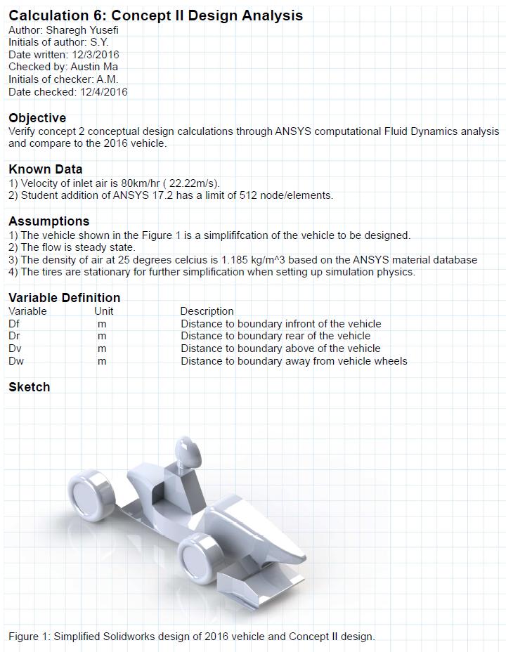
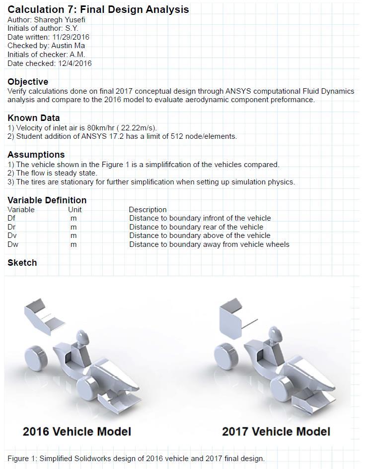
8 2 1.4 DESIGN CONSIDERATION REVISIONS Triple G Engineering recreated the CFD analysis for the 2016 vehicle using a simplified SolidWorks model. The same simplifications on the main body of the vehicle were used for the 2017 model so that consistent comparison can be made between the new and old aerodynamic components. Figure 1 shows the SolidWorks assemblies used for comparison. Figure 1: Simplified SolidWorks models for the 2016 and 2017 SAE vehicle. The results obtained from the CFD analysis of the 2016 vehicle were different from the values originally provided from the client in Phase I. Consequently, changes were made to the specification matrix to show the new values. The changes to the specification matrix are shown in an updated compliance matrix in section 4 of the report. These changes are also highlighted below. Downforce: CFD analysis showed that the 2016 vehicle produced only 490 N of downforce instead of the 547 N specified by the client. Downforce to Drag Ratio: The actual downforce to drag ratio of the 2016 vehicle is 1.47 instead of 1.85 specified by the client. Weight: A 0.7 mm thickness was used for the SolidWorks model of the carbon fibre components in the 2016 vehicle. This is unrealistic and a 3 mm thickness was used. As a result, the mass of the previous aerodynamic components increased to 25.6 kg.

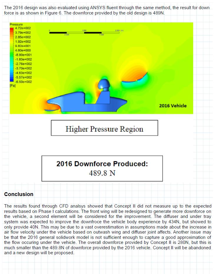
9 3 2 FINAL DESIGN 2.1 DESIGN SUMMARY The chosen final design was considered as an iterative process to meet the client specifications. Coming out of Phase II of the project, Concept II was considered and evaluated using ANSYS Fluent. The design composed of a front wing assembly with a new wing profile, outwash endplates, and an undertray-diffuser underbody as shown in Figure 2. Figure 2: Concept II vehicle and aerodynamic components Detailed CFD simulations showed that preliminary calculations which favoured Concept II were overestimated. The detailed calculations are shown in Appendix C Calculation 6. The error was due to a two reasons: overestimating the downforce expected from the effects of the outwash end plates and diffuser combination, and the 2016 vehicle model created for comparison did not capture the flow effects which actually occur under the vehicle. In order to meet the client s specifications, a variation of Concept 1 was considered and evaluated. Concept 1 consists of a front wing, rear wing, rear wing mounting system, and flat end plates for the wings as displayed in Figure 3.

10 4 Figure 3: Concept I and aerodynamic components Various wing profiles were considered to meet the desired increase in downforce from the 2016 vehicle. The design selection and evaluation was an iterative process as outlined in the process flow diagram below shown in Figure 4. Figure 4: Design process flow chart.
11 5 2.2 DESIGN REFINEMENTS After running simulations through ANSYS fluent, it was found that multi element wings were necessary for the front and rear wings to meet the desired downforce on the 2017 vehicle. Outwash endplates were considered to decrease drag effects on the vehicle to meet the desired downforce to drag ratio specified by the client. An aerodynamic mounting system was also designed to hold up the rear wing assembly Front and Rear Wing It was concluded through initial CFD analysis that the lift coefficient of the Liebeck LA5055 airfoil is not as high as originally assumed in Phase II. An overestimation of the ground effect had also been made which is why the front wing was not generating as much downforce as originally predicted. See Appendix C for analysis of the ground effect. A two element front and rear wing was implemented to meet the downforce requirements. Multiple CFD simulations were created to determine the main element angle, flap angle, and flap size to meet the downforce required. The CFD analysis for the wing was performed on ANSYS CFX Student Edition as shown in Appendix C. The downforce, drag force, and lift to drag ratio were calculated for the main element with 2 o, 6 o, 8 o, 9.5 o, and 12 o angles of attack as shown in Figure 5. Results showed that an angle of attack at roughly 9.5 o generated a large amount of downforce while also minimizing drag. Further increase in the angle of attack meant a small increase in downforce but a large decrease in lift to drag ratio.
12 Downforce (N) Lift to Drag Ratio Angle of Attack of Main Element (Degrees) Down Force L/D Figure 5: The downforce and lift to drag ratio for varying angle of attacks. CFD results showed that downforce can be increased by using a steep flap angle or a large flap; however, a steeper flap angle will result in a decrease in lift to drag ratio while a large flap will have little effect on the lift to drag ratio (Figure 6). Detailed analysis of the flap angle and size are shown in Appendix C. In this case, a large flap is used along with a steep angle of attack because the main objective is to maximize downforce. The decrease in the lift to drag ratio is justified because the implementation of front outwash wing are used to minimize drag of the overall vehicle.
13 Downforce Lift to Drag Ratio Angle of Attack of Flap Angle of Attack of Flap Figure 6: The downforce (left) and lift to drag ratio (right) plotted for different flap angles and sizes. The final sizes and angle of attacks for the front and rear wing is highlighted in Figure 7. A flap chord length ratio of 0.5 was used for both the front and rear wing. The angle of attacks for the main element and flap are 9.5 o and 40 o respectively for both wings. A larger rear wing was required because the rear wing is unable to take advantage of the ground effect. Figure 7: Dimensions and configuration for the front and rear wing.

 and final iteration (right) of outwash endplates By iteratively modifying the geometry of the outwash endplate, the final design was able to increase downforce by 40")
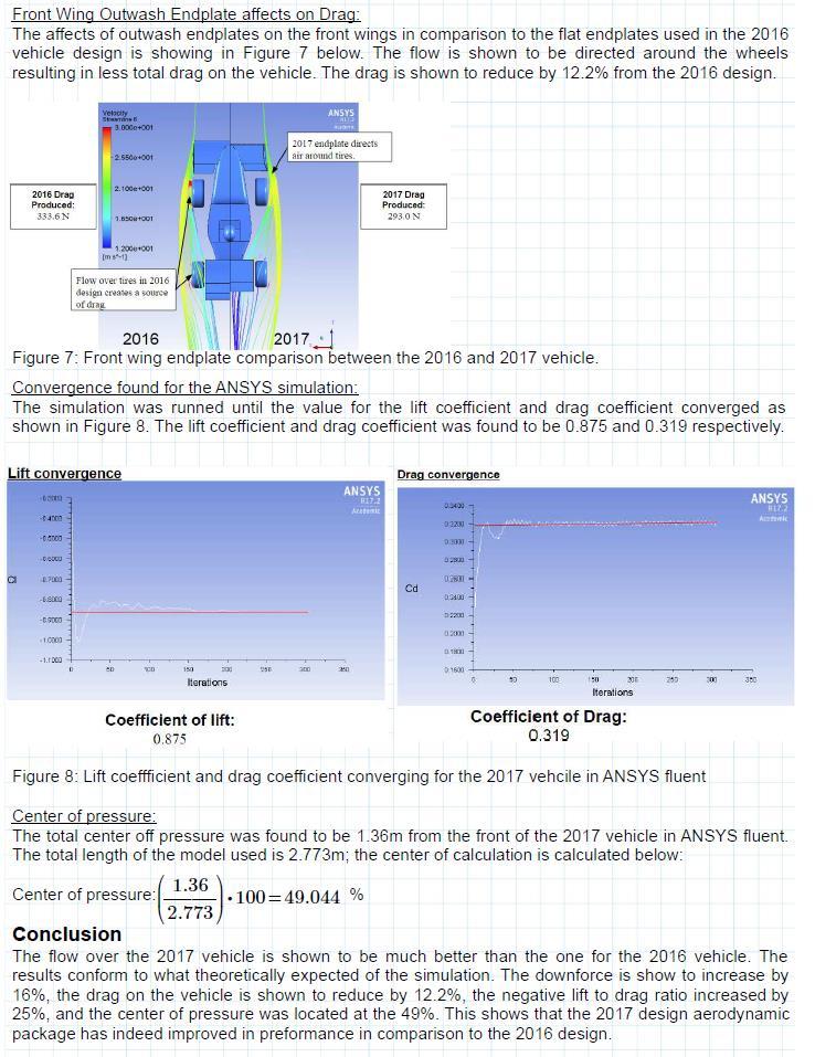
14 Outwash To determine the optimal geometric design of the outwash endplates, iterative CFD simulations were done on a half model that included the nose, front tires, and front wing in its geometry. Small changes were then made to the shape of the endplate. These changes were various plate angles, footplate curvature and cone lengths/cone angles. Figure 8 shows the comparison of the initial design to the final chosen design. Figure 8: First iteration (left) and final iteration (right) of outwash endplates By iteratively modifying the geometry of the outwash endplate, the final design was able to increase downforce by 40 N and reduce drag by 8 N. These end plates were then put into a model with the whole vehicle and a comparative analysis was done with the 2016 design. Figure 9 shows the velocity streamline comparison.

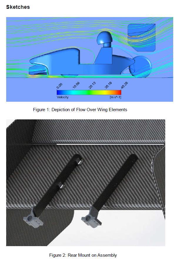
15 9 Figure 9: Streamline diagram showing the effect of front outwash endplates. As Figure 9 shows, air is clearly redirected around the tires and below the rear wing. The combined effect of the wing profiles chosen and the outwash endplates is a 12% decrease in drag force Rear Wing Mounting System The rear wing mounting assembly shown in Figure 10 is used to attach the rear wing to the chassis. The parts of the assembly are shown in Figure 11 in order of assembly, and it consists of two aluminum pipe brackets that attach to the pipe frame chassis of the vehicle and bolts to the carbon fiber plates. The carbon fiber plates themselves are attached to the rear wing through an aluminum connector that bolts to the rear wing and the carbon fiber plate. This assembly keeps the rear wing in position during operation.

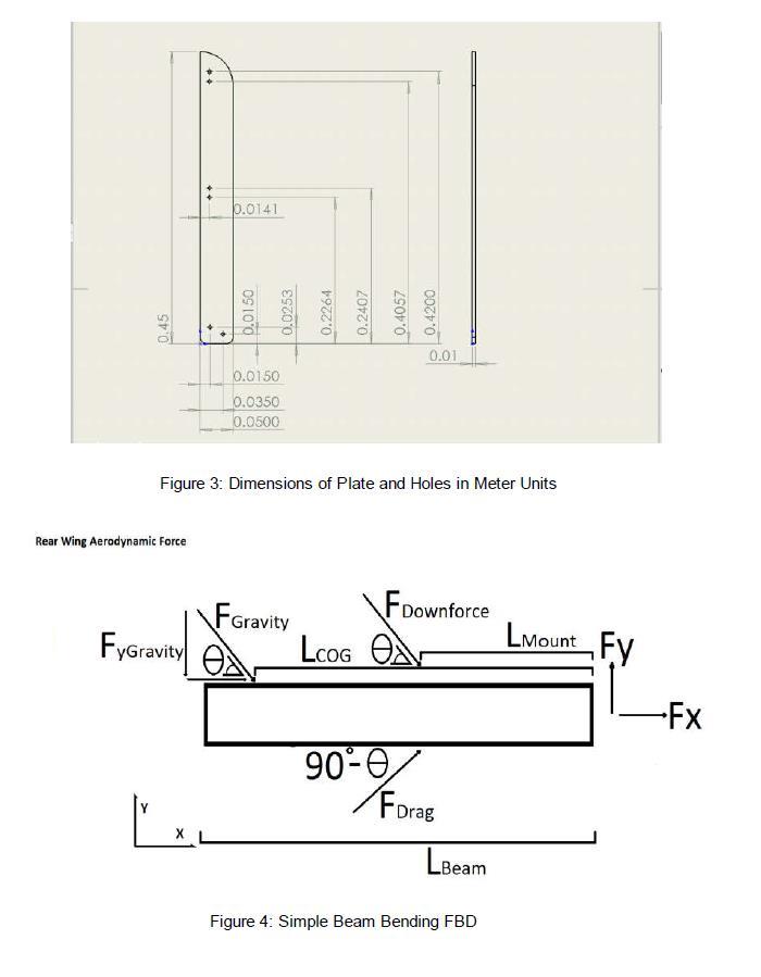
16 10 Figure 10: Rear wing mounting assembly. From Phase II the method of attaching the mount to the chassis was refined to a pipe bracket capable of mounting to the rear loop of the frame while compensating for the angular pipe orientation. The plate itself is was redefined into carbon fiber to reduce the geometry and weight and designed to a rectangular shape. This design allows the part to form from a single mold for ease of manufacturing, and to present minor effects to drag performance. The plates are designed to have a width of 50mm and thickness of 7.5mm. The plates experience a deflection of 0.17mm which is less than the 25mm limit given by FSAE Rule T9.7.1 [1]. These calculations can be found in Appendix B.

17 11 Figure 11: Exploded view of the rear mounting assembly. The effect of the Mounting assembly on the aerodynamic performance will be minimal due to mounting from the top edge and the thin rectangular shape of the mount. However the strength and stability of the component are much greater than required. 2.3 MATERIALS AND MANUFACTURING The aerodynamic package will be constructed using Hexcel 4ASC carbon fibre with T6 aluminum for framing. These materials were chosen due to their light weight, high strength in addition to low cost and easy accessibility through client sponsorships. The client provided a specific manufacturing method for carbon fiber wings that has been used to make wings in the past through the University of Alberta machine shop. Therefore Triple G Engineering designed the wings to be manufactured through this process which requires ordering carbon layers and epoxy. The manufacturing of aluminum components will be done by waterjet cutting stock aluminum sheets. 2.4 INSTALLATION AND TRANSPORTATION The mounting assembly for both the front and rear wing have separate components for mounting to the chassis and attaching to the wings. The wings are capable of being installed and removed easily for storage and transportation using bolts and nuts.


18 12 The 2017 assembly composes of a front inboard endplate which is bolted into the 2016 vehicle front wing mount sheer component; this is shown in Figure 12. The mounting brackets are bolted to the front inboard endplates to hold up the wing assembly. Figure 12: Front wing assembly installation components The rear wing is bolted into the mounting assembly through the use of mounting brackets as shown in Figure 13. The Mounting system is then bolted into the chassis through the mounting brackets. Figure 13: Rear wing assembly installation components
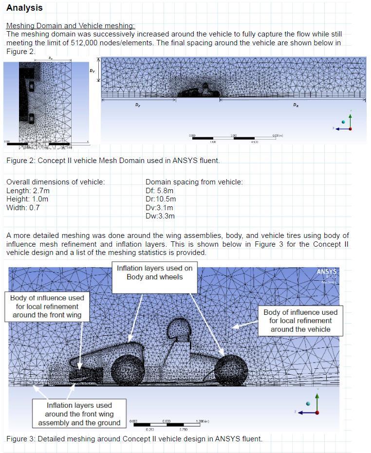
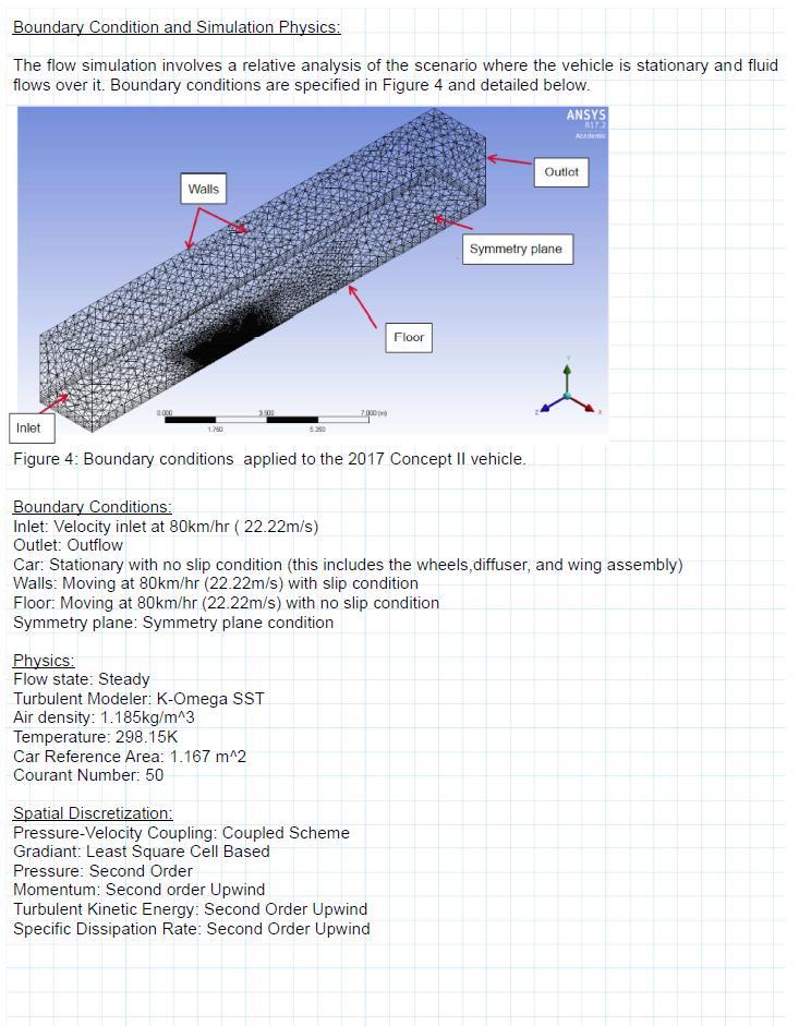
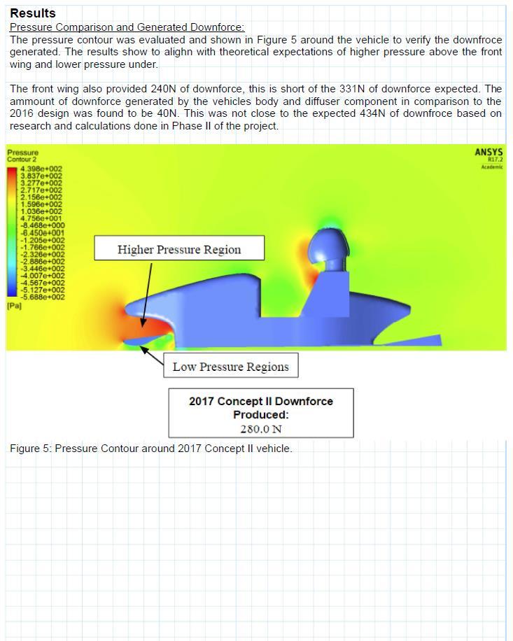
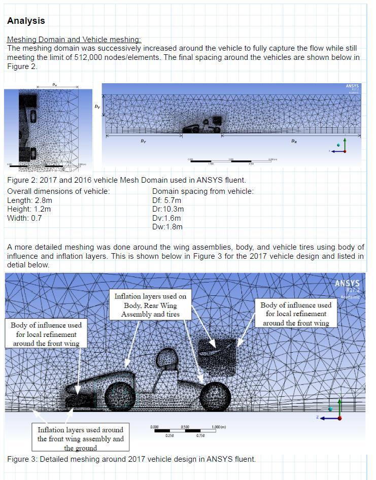
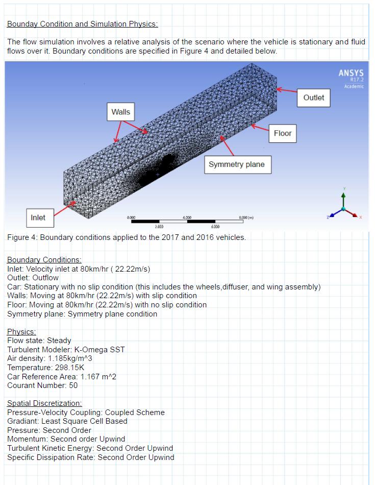
19 OTHER INDUSTRIAL DESIGN CONSIDERATIONS Almost all the components used in the aerodynamic package will be made from Hexcel 4ASC carbon fibre. Recycling carbon fibre is difficult due to the need to strip away the epoxy resin from the layers of fibre [2]. However, the environmental impact of the design is limited because only one aerodynamic package will be created for the 2017 Formula SAE vehicle. The front and rear wings are both hollow which minimizes the total amount of material used. Sustainability was not a design concern for the aerodynamic package because the vehicle will only be used for FSAE competitions. The aerodynamic components will be made mostly of carbon fibre which will provide durability. Regardless, a new vehicle is created by the University of Alberta FSAE team annually. The front and rear wing assembly can be reused for future vehicles if the Formula SAE team desires. Individual components such as the end plates, wings, and flaps are easily detached from their assembly so the FSAE team can reuse only the components they want in the future. The front and rear wing assembly can be attached to a new vehicle body by redesigning only the mounting system. 3 CRITICAL ANALYSIS 3.1 CFD ANALYSIS The vehicle used for in 2016 was simplified in SolidWorks and tested in ANSYS Fluent against the proposed 2017 design. Appendix C shows comparative analysis of the considered domain around the vehicle, specific meshing, and results of the simulations evaluated. The domain was successively increased around the vehicle to capture the flow without it being affected by the boundaries set. ANSYS 17.2 student edition was used, so there was a limit of nodes/elements; this limit was met when creating the domain. Finer meshing was done around the vehicle wing assemblies. Inflation layers were used to get more accurate simulation of flow effects on the vehicle. The flow was assumed to be steady state and the turbulence was modeled using k-omega SST. The courant number was chosen to be 50 for the simulation while employing second order upwind advection scheme. The final design model is depicted in Figure 14 below with labeled components.

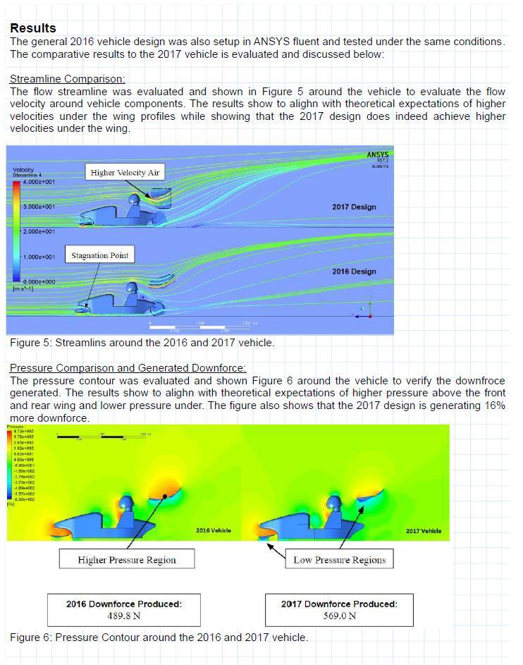
20 14 Figure 14: The final design with labeled key components. The results found for the 2016 and 2017 vehicle are displayed in Table 1. The 2017 design provides 569 N of downforce which is an increase by 16% from the 2016 design, the drag on the 2017 vehicle is shown to reduce by 12.2%, the negative lift to drag ratio increased by 25%, and the center of pressure was located at the 49%. The results shows that the 2017 design aerodynamic package has improved in performance from the 2016 design. The must have client specifications in performance are met. To meet the performance specifications weight and cost were compromised within reasonable margins. Table 1: Summary of results for the 2016 and 2017 vehicle. Specification 2016 Aero Package 2017 Aero Package Criteria Downforce N N 10% increase Drag Force N N Reduction in drag Lift to Drag Ratio Increase by 25% Total Mass kg kg Minimized Total Cost $ $ Minimized
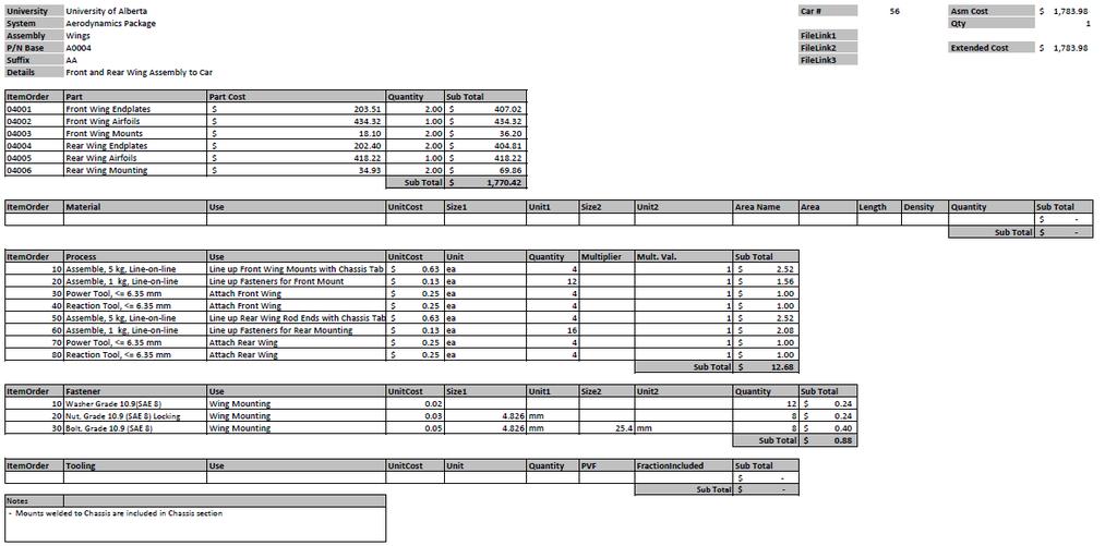
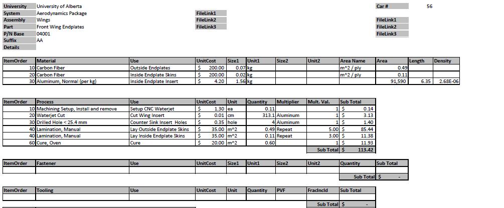
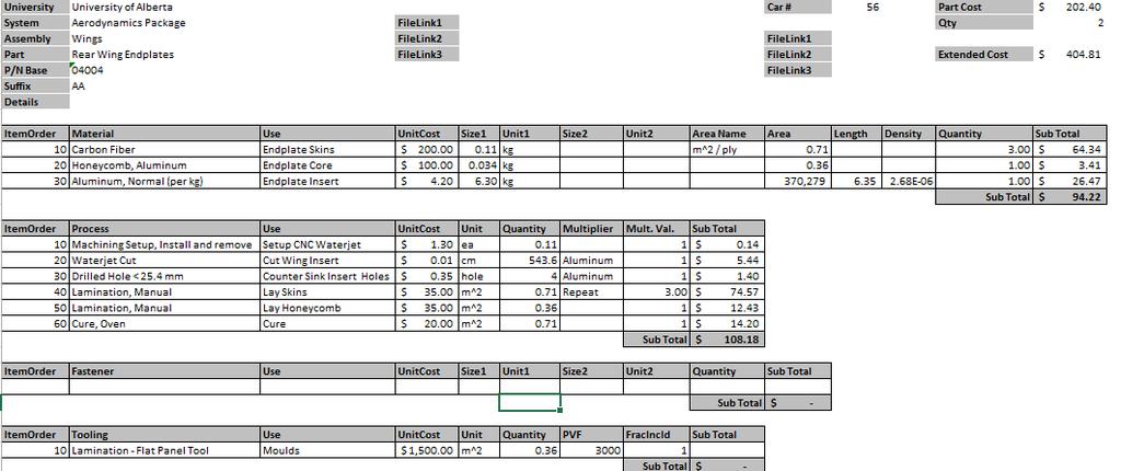
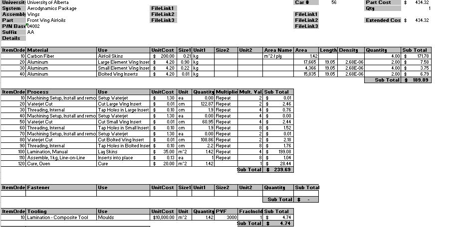
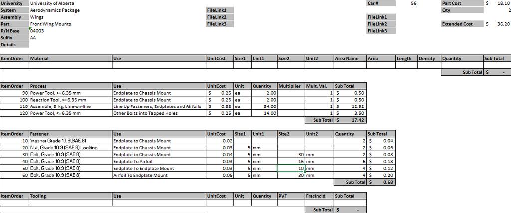
21 MANUFACTURING AND MATERIALS COST The total manufacturing and material cost for each component are shown in Table 2 below. Cost estimates are based on FSAE material and manufacturing rates which include sponsorship discounts. The total material cost is $751 which is an 18% increase from the former aerodynamic package. Total manufacturing cost is $1010, equating to an increase of 14%. Increase in both manufacturing and material cost was necessary for the implementation of larger, more complex endplates. Table 2: Total cost broken down by components. Part Part Cost Quantity Subtotal Front Wing Endplates $ $ Front Wing Airfoils $ $ Front Wing Mounts $ $36.20 Rear Wing Endplates $ $ Rear Wing Airfoils $ $ Rear Wing Mounting $ $69.86 Total $1, DESIGN COMPLIANCE MATRIX Triple G Engineering was able to meet all the physical specifications as required by the FSAE rules. At the same time, the final design of the aerodynamic package was able to meet almost all of the specifications requested by the client. The design compliance matrix is shown in Appendix A. 4.1 EVALUATION/DISCUSSION/CLIENT APPROVAL Triple G Engineering was able to meet all specifications that were assessed a weighting of 4 and higher (must haves). A 16% increase in downforce was generated by the final design, which is more than the 10% requested by the client. The downforce to drag ratio was also increased to Oversteering was achieved by generating a center of pressure that was located at the 49th percentile of the vehicle s length. An increase in both material and manufacturing cost was required to create more complex end plates. The total mass of the aerodynamic components also
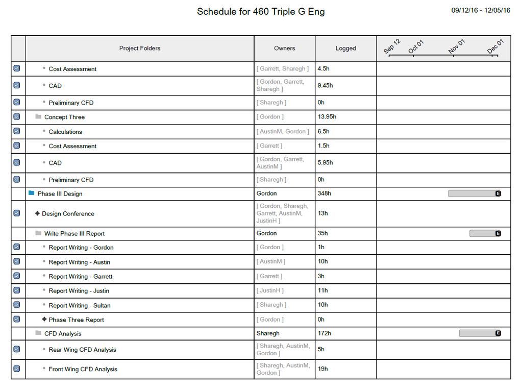
22 Hours 16 increased due to larger rear wing end plates. Increases in both cost and mass were justified within reasonable margin for the significant increase in performance. The design of the aerodynamic package has been approved by the client Chris Taschuk. 5 FUTURE WORK A finer analysis of the 2017 design should be done on the final design using the full ANSYS license for better accuracy. The project was limited in time and resources, so it is recommended that concept two diffuser analysis is further investigated. Further research into hollow carbon fiber endplates is recommended to decrease overall weight and cost of the design. 6 PROJECT MANAGEMENT 6.1 SCHEDULE At the end of Phase II, an estimated hours was required to complete the entire project; the actual total number of hours spent on the project was Majority of the time were spent on redesigning final concept to meet the client s criteria. A comparison between the total number of hours spent on the project and the estimated time required is shown in Figure 15 below Actual Time Updated Estimate Phase of Design Figure 15: Estimated and actual engineering hours
23 BUDGET Triple G Engineering has developed a total engineering cost of $60,525 based on the number of hours spent on designing the aerodynamic package. The number of hours spent on the project, broken down into the three phases, are shown in Table 3 below. There was no budget limit established by the client for the total engineering cost. The cost for engineering hours are $90 per hour for junior engineering and 150$ per hour for intermediate engineers. Table 3: Total engineering cost broken down by each phase. Stage Junior Engineer Hour Intermediate Engineer Hours Cost ($) Phase I ,755 Phase II ,770 Phase III ,000 Total ,525 7 CONCLUSION The aerodynamic package was designed through an iterative process. Concept II was initially evaluated and found to not meet the client specifications. Concept I was considered with improvements on the wing dimensions and endplates. The final design is a double element front and rear wing featuring outwash end plates and a mounting system. Results for the final design include a 16% increase in downforce, 12% decrease in drag, improvement in the lift to drag ratio by 25%, and a center of pressure located at the 49th percentile of the car length. An increase in cost and mass were needed for larger and more complex end plates; the design does meet the client specifications. A total of Engineering hours was provided for the project, this associates with a total cost of $60,525.
24 18 ACKNOWLEDGEMENT We would like to acknowledge Dr. Carlos Lange, Mr. Chris Taschuk, and Dr. Michael Lipsett for their guidance and cooperation with Triple G Engineering.
25 19 REFERENCES [1] Formula SAE Rules, SAE International, 2016, [Online]. Available: FSAE Rules PRELIMINARY.pdf. [Accessed: 29-Nov- 2016] [2] Recycling Carbon Fibre Composites, Materials Today, 2016, [Online]. Available: [Accessed: 03-Dec-2016]
26 20 APPENDIX A DESIGN COMPLIANCE MATRIX
27 21 Item Citeria Specification 1. Dimensions 1.1 Front Wing Width 1.2 Front Wing Forward Location 1.3 Front Wing Height 1.4 Rear Wing Width 1.5 Rear Wing Height 1.6 Rear Wing Forward Location Rear Wing Rearward 1.7 Location 2. Performance 2.1 Downforce 2.2 Weight 2.3 Downforce to Drag Ratio 2.4 Aerodynamic Balance 2.5 Force Transmission 2.6 Adjustable Angle of Attack 2.7 Outwash Wing Must not be wider than the outer face of the front tires Must not be further than 700 mm forward of the front tires Must not be higher than 250 mm from ground excluding the end plates Must not be wider than outer face of the rear tires Must not be higher than 1.2 m above ground without the driver Must be located behind the front face of the driver head restraint support Must not be further than 250 mm behind the rear tires 10% increase in total downforce (Currently 490 N 547 N at 80 kmh) Maintain or reduce weight of the current design (25.6 kg 8 kg) Maintain or improve the current downforce to drag ratio ( ) The center of pressure should be located in front of the center of mass in order to produce an oversteer Mount wings to transmit force directly to wheels Multiple angles of attack that can be easily adjusted to change the distribution of downforce Design front wing endplates to direct air around the tires Design Authority Weighting Specification Met? Formula SAE 5 Yes Formula SAE 5 Yes Formula SAE 5 Yes Formula SAE 5 Yes Formula SAE 5 Yes Formula SAE 5 Yes Formula SAE 5 Yes Client 4 Yes Client 3 No Client 4 Yes Client 4 Yes Triple G Engineering Triple G Engineering Triple G Engineering 2 Yes 1 Not Considered 2 Yes Final Design Specification The width of the front wing assembly is 1452mm, which is less than the outer face of the front tires (1455 mm). The front wing is located 652 mm from the front tires. The maximum height of the front wing is 249 mm from the ground. The width of the rear wing assembly is 790 mm, which is less than outer face of the rear tires (1307 mm). The maximum height of the rear wing is 1190 mm from the ground. Rear wing is located behind the front face of driver's head restraint support. The rear wing does not extend behind the rear tires. The downforce generated by the final design is N, which corresponds to a 16% increase in downforce. The total weight for the final design of the aerodynamic package is 27.7 kg. An overall downforce to drag ratio of 1.94 was obtained for the final design of the aerodynamic package. Center of pressure is at the 49%, the center of mass is at 50% with a 68 kg driver. Swan neck mounting was used for the rear wing to transmit downforce directly to the wheel. Not considered due to time constraint. The value added by this feature was considered minimal. Outwash endplates used for the front wing, reducing the overall drag force of the vehicle from 334 N to 293 N.
28 22 3. Safety 3.1 Minimum Radii 3.2 Overall Strength and Stability 3.3 Mounting Material 4. Cost 4.1 Material Cost Forward and horizontal edges must have a minimum radius of 5 mm. Vertical edges must have a minimum radius of 3 mm. 200 N may be applied and the resulting deflection should not be more than 25 mm and any permanent deflection must be less than 5 mm. Requires a yield strength of 180 MPa and ultimate strength of 300 MPa Maintain or reduce previous design cost of $ Maintain or reduce previous 4.2 Manufacturing Cost design cost of $ Other Design Considerations The front and rear wing should be easy to install and 5.1 Installation remove The front and rear wing should be removable for 5.2 Transportability transportation of the vehicle Must be able to mount onto Compatibility with the current chassis and 5.3 Current Design Frame suspension 5.4 Manufacturability 5.5 Aesthetics Must be simple to manufacture with the resource available to the Formula SAE team The appearance of the design can be unique and creative Formula SAE 5 Yes Formula SAE 5 Yes Formula SAE 5 Yes Client 3 No Client 3 No Triple G Engineering 2 Yes Client 3 Yes Client 4 Yes Client 4 Yes Triple G Engineering 1 Yes All forward and horizontal facing edges have a radius of greater than 5 mm. The maximum deflection occuring at the rear wing was calculated to be 15 mm. Mounting bracket material ultimate strength is 4.13 GPA. The total material cost for the final design of the aerodynamic package is $750. The total manufacturing cost for the final design of the aerodynamic package is $1000. Bolts and nuts are used for easy installation of the front and rear wing mounting system. Detachable assemblies for easy transportation. Mounts onto current chassis and suspension. Components will be manufactured using the same process as the previous aerodynamic package. Usage of complex front outwash end plates and multi element wings creates an aerodynamic look.
29 23 APPENDIX B HAND CALCULATIONS
30 24
31 25
32 26
33 27
34 28
35 29
36 30
37 31 Calculation 2: Fastener Analysis Author: G.S November 25, 2016 Checked by: A.M. December 4, 2016 Revision number: 02 December 4, 2016 Revision checked by: A.M. December 4, 2016 Objective The purpose of this calculation is to verify that the fasteners used to attach the wings and endplates will not fail under the forces generated by the aerodynamic package. Known Data 1. Force on fastener P 200N 2. Material Thickness t m 6.25mm 3. Preload fraction f p Washer Thickness t w 0mm 5. Material Modulus E a 70GPa 5.0 mm Grade 5.8 Bolts 6. Bolt diameter d 5mm 7. Proof Strength S p 380MPa 8. Yield Strength S y 420MPa 9. Ultimate Strength S ut 520MPa 10. Bolt Length l 30mm 11. Bolt Modulus E b 200GPa 12. Tensile Area of Bolt [Table 9-1] A t 14.18mm 13. Number of Bolts N 4 At and strengths from Figures 9-1 and 9-3 [1] Assumptions 1) Analysis is completed for highest stress fastener to ensure no fasteners will fail 2) Fasteners to hold for standard loading and are not expected to hold high impact loading as other components will yield first

38 32 Sketch Figure 1: Free body diagram of bolt. [2] Analysis
39 33
40 34 Conclusion The selected Grade 5.8 fasteners or ones of greater strength will be acceptable for all mounting connections on the aerodynamic package. References [1] Dr. James Carey MecE 360 Note Package [2] Image from
41 35 APPENDIX C CFD ANALYSES


42 36 Calculation 3: Investigating the Downforce Increase of Ground Effect Author: A.M. December 1, 2016 Checked by: S.Y. December 2, 2016 Revision number: 02 December 2, 2016 Revision checked by: S.Y. December 2, 2016 Objective The purpose of this analysis is to verify an assumption made about the ground effect in Phase II. According to Katz, a 50% increase in downforce is easily achieved if a wing is close to the ground [1]. Two simulations will be created for this analysis to show the effect of the ground on downforce. Since the rear wing is unable to take advantage of the ground effect, quantifying the ground effect will allow Triple G Engineering to size the rear wing accordingly. Known Data 1. The selected airfoil profile is Liebeck LA The density of air at 25 o C is kg/m 3 based on the ANSYS material database. 3. The width of the wing is 1.30 m. 4. The chord length of the main element used in the analysis is 375 mm. Assumptions 1. The flow is steady state. 2. The wing will be positioned 2.5 (63.5 mm) from the ground for the first simulation. 3. The wing will be positioned with at the center of the domain with 1 m clearance at the top and bottom. Variable Definition Variable Units Definition L N Downforce produced by the wing Sketch Figure 1: A comparison between the two domains used for the analysis. The left shows a domain with the wing placed close to the ground. The right shows a domain with the wing placed at the center.


43 37 Analysis Meshing Domain and Sizing For the first simulation, the wing is placed near the bottom wall with a clearance of 63.5 mm. This simulation will be used to determine the downforce generated by a wing that is close to the ground. Figure 2 shows the domain and mesh details of this simulation. The wing is placed at the center of the enclosure in the second simulation. Figure 3 shows the domain used for the second simulation. In both cases, there is a 2 m clearance from the inlet and outlet boundaries. A 375 mm Liebeck LA5055 airfoil with a 9.5 o angle of attack is used for both simulations. Figure 2: The domain and mesh detail used for first simulation to represent ground effect. Figure 3: The domain and mesh detail used for the second simulation where there is no ground effect. A cylindrical body of influence was placed around the wing so minimize the size of the mesh for the region around the wing. Inflation layers were used on the surface of main element, flap. Inflation was only used in the first simulation where the bottom wall was treated as the ground. Mesh statistics and settings for both simulations are provided in Table 1.
44 38 Table 1: A summary of the meshing used for the CFD analysis. Inflation at Wing Inflation at Ground Body of Influenc e Overall Meshing Details 1. Simulation with Ground Effect 2. Simulation without Ground Effect Number of Layers 5 Number of Layers 5 Growth Rate 1.2 Growth Rate 1.2 Maximum Thickness (m) 0.01 Maximum Thickness (m) 0.01 Number of Layers 5 Number of Layers N/A Growth Rate 1.3 Growth Rate N/A Maximum Thickness (m) 0.05 Maximum Thickness (m) N/A Element Size (m) Element Size (m) Size Function Uniform Size Function Uniform Growth Rate 1.2 Growth Rate 1.2 Size Function Uniform Size Function Uniform Min Size (m) Min Size (m) Max Face Size (m) Max Face Size (m) Max Tet Size (m) Max Tet Size (m) Growth Rate 1.2 Growth Rate 1.2 Nodes Nodes Elements Elements
45 39 Boundary Condition and Simulation Physics The setup for the CFD analysis and boundaries are shown in Figure 4. Inlet Walls Ground Outlet Figure 4: A schematic of the setup for the two simulations. Boundary Conditions: Inlet: Velocity inlet at 80 km/hr (22.22 m/s) Outlet: Zero pressure differential. Walls: Free slip wall Ground: No slip wall moving at 80 km/h (22.22 m/s) for the simulation with ground effect. Free slip wall for the simulation without ground effect. Wing: No slip stationary wall. Physics Flow state: Steady Turbulence Model: K-Omega Shear Stress Transport (SST) Air Density: kg/m 3 Temperature: K Advection Scheme: Pure Central Differencing Scheme The velocity underneath the wing was monitored for each iteration. Figure 5 shows the convergence of the velocity underneath the wing for both simulation. The small oscillations of the velocity is caused by the central differencing advection scheme. Note that the y-axis for both chart is zoomed in so the oscillations are small.
46 40 Figure 5: The x component of the velocity below the wing by iteration for both simulation. The left graph shows the convergence for simulation with ground effect. The right graph shows the convergence for simulation without ground effect. Results The results showed that the wing produced a downforce of 141 N with ground effect, and only 116 N without ground effect. This corresponds to a 21.4% increase in downforce. Conclusion The analysis shows that the ground effect will result in approximately 21% increase in downforce for a 375 mm long Liebeck LA5055 airfoil. The assumption that the ground effect will provide a 50% increase in downforce was an overestimation. As a result, a double element wing must be used to increase downforce performance of the front and rear wing. A larger rear wing will be used to compensate for the loss of downforce due to ground effect. References [1] J. Katz, Race Car Aerodynamics. Cambridge, MA, USA: R. Bentley, 1995.

47 41 Calculation 4: Selecting Angle of Attack for the Main Element Author: A.M. December 1, 2016 Checked by: S.Y. December 2, 2016 Revision number: 02 December 2, 2016 Revision checked by: S.Y. December 2, 2016 Objective The purpose of this calculation is to determine the optimum angle of the main element to maximize downforce and minimize drag. The front and rear wing will both use this angle of attack for the main element. Computational fluid dynamics (CFD) for this calculation was done using ANSYS CFX Student Edition. The downforce and drag force were computed for angle of attack of 2 o, 6 o, 8 o, 9.5 o, and 12 o. Known Data 5. The selected airfoil profile is Liebeck LA The density of air at 25 o C is kg/m 3 based on the ANSYS material database. 7. The width of the front and rear wing is 1.30 m. 8. The chord length of the main element used in the analysis is 375 mm. Assumptions 4. The flow is steady state. 5. The wing will be positioned 2.5 from the ground. Variable Definition Variable Units Definition D N Drag force produced by the wing L N Downforce produced by the wing L/D None Downforce to drag ratio α Degrees Angle of attack of the main element Sketch Figure 1: 3-D model of the Liebeck LA5055 main element.


48 42 Analysis Meshing Domain and Sizing The meshing domain was created to ensure that the flow around the wing and the wake region behind the wing are captured. A 2.5 clearance was placed between the wing and the bottom wall to model the ground effect of the front wing. There is a 2 m clearance in front and behind the wing to ensure both a fully developed flow when the air hits the wing and to capture the wake region behind the wing. The meshes were sized so that the flow around the wing is accurately captured while meeting the limit of 512,000 nodes for the student version of ANSYS. The domain used for the analysis is shown in Figure 2. Figure 2: The domain and mesh detail used for the analysis of the front wing. A cylindrical body of influence was placed around the wing to increase the accuracy of the flow around the wing. Inflation layers were also placed on the wing and at the ground to obtain a more accurate solution of the flow near the wall due to boundary layers. The effects of these refinement are shown in Figure 3. Statistics for the mesh are summarized in Table 1. Note that the number of nodes and elements for each simulation are different, so an approximate value was given. Inflation layers around the wing to capture the effect of boundary layer. Body of influence to refine mesh around the wing. Inflation layers on the ground to capture the effect of boundary layer. Figure 3: A close up view of the mesh around the wing and near the ground.
49 43 Table 1: A summary of the meshing used for the CFD analysis. Inflation Layer at Wing Number of Layers 5 Growth Rate 1.2 Maximum Thickness (m) 0.01 Inflation Layer at Ground Number of Layers 5 Growth Rate 1.2 Maximum Thickness (m) 0.01 Body of Influence Element Size (m) Size Function Uniform Growth Rate 1.2 Overall Meshing Detail Size Function Uniform Min Size (m) Max Face Size (m) Max Tet Size (m) Growth Rate 1.2 Nodes ~ Elements ~850000
 Outlet: Zero pressure differential.")
50 44 Boundary Condition and Simulation Physics The boundary conditions were set up to create a good representation of the real scenario. These boundary conditions are highlighted in Figure 4. Inlet Walls Ground Outlet Figure 4: Boundary conditions applied to the simulation of the wing. Boundary Conditions: Inlet: Velocity inlet at 80 km/hr (22.22 m/s) Outlet: Zero pressure differential. Walls: Free slip wall Ground: No slip wall moving at 80 km/h (22.22 m/s) Wing: No slip stationary wall. Physics Flow state: Steady Turbulence Model: K-Omega Shear Stress Transport (SST) Air Density: kg/m 3 Temperature: K Advection Scheme: Pure Central Differencing Scheme A monitoring point was also placed under the wing to monitor the convergence of the velocity. A sample convergence chart is shown below in Figure 5.
51 45 Figure 5: The x component of the velocity below the wing by iteration. Results The downforce, drag force, and lift to drag ratios were calculated for the wing at angle of attacks of 2 o, 6 o, 8 o, 9.5 o, and 12 o. These results are summarized in Table 2 and plotted in Figure 6. Table 2: The downforce, drag force, and lift to drag ratio for a Liebeck 5055 wing at different angle of attacks. Angle of Attack (degs) Down Force (N) Drag Force (N) L/D
52 L, Downforce (N) L/D, Lift to Drag Ratio α, Angle of Attack of Main Element (Degrees) Down Force L/D Figure 6: Downforce and lift to drag ratio plotted against varying angle of attacks. From the results shown in Figure 5, the downforce increase generated by increasing the angle of attack from 9.5 o to 12 o was minimal (+2.7% increase). On the other hand, by increasing the angle of attack from 9.5 o to 12 o, the lift to drag ratio decreased from 6.50 to An angle of attack of 9.5 o for the main element was selected because this provided a large amount of downforce while also minimizing the drag created. Conclusion The downforce, drag force, and lift to drag ratio were calculated for the main element for angle of attacks of 2 o, 6 o, 8 o, 9.5 o, and 12 o. Results showed that an angle of attack at roughly 9.5 o generated a large amount of downforce while also minimizing drag. Further increase in the angle of attack meant a small increase in downforce but a large decrease in lift to drag ratio.
53 47 Calculation 5: Selecting a Flap Angle and Flap Size Author: A.M. December 1, 2016 Checked by: S.Y. December 2, 2016 Revision number: 02 December 2, 2016 Revision checked by: S.Y. December 2, 2016 Objective The purpose of this calculation is to select a flap angle and flap size that produces the maximum downforce while minimizing drag. Computational fluid dynamics (CFD) for this calculation was done using ANSYS CFX Student Edition. Flap angles of 25 o, 30 o, 35 o, and 40 o were considered for the analysis. Flaps with a chord length ratio of 0.35, 0.40, 0.45, and 0.50 were considered. The analysis will be done on the front wing, but the rear wing will use a similar setup. Known Data 9. The selected airfoil profile is Liebeck LA The density of air at 25 o C is kg/m 3 based on the ANSYS material database. 11. The width of the front and rear wing is 1.30 m. 12. The chord length of the main element used in the analysis is 375 mm. 13. The required downforce for the front wing is 331 N Assumptions 6. The flow is steady state. 7. The wing will be positioned 2.5 from the ground for the analysis. 8. The wing will feature two elements, a main element and a flap. Variable Definition Variable Units Definition D N Drag force produced by the wing L N Downforce produced by the wing r None Ratio between flap length to main element length θ Degrees Angle of attack of the flap Sketch Main Element Flap Figure 1: A simple sketch of a two-element airfoil.


54 48 Analysis Meshing Domain and Sizing A 2.5 clearance was placed between the two element wing and the bottom wall to model the ground effect of the front wing. There is a 2 m clearance in front and behind the wing to ensure both a fully developed flow when the air hits the wing and to capture the wake region behind the wing. The meshes were sized so that the flow around the wing is accurately captured while meeting the limit of 512,000 nodes for the student version of ANSYS. The domain used for the analysis is shown in Figure 2. Figure 2: The domain and mesh detail used for the analysis of the multi element wing. A cylindrical body of influence was placed around the wing so minimize the size of the mesh for the region around the wing. Inflation layers were used on the surface of main element, flap, and at the ground to obtain a more accurate solution near the wall due to boundary layers. A zoomed in view of the mesh is provided in Figure 3. Mesh statistics are provided in Table 1. Note that the number of nodes and elements for each simulation are different, so an approximate value was given. Inflation layers around the wing to capture the effect of boundary layer. Body of influence to refine mesh around the wing. Inflation layers on the ground to capture the effect of boundary layer. Figure 3: A zoomed in view of the mesh around the wing and near the ground.
55 49 Table 1: A summary of the meshing used for the CFD analysis. Inflation Layer at Wing s Surface Number of Layers 5 Growth Rate 1.3 Maximum Thickness (m) 0.01 Inflation Layer at Ground Number of Layers 5 Growth Rate 1.2 Maximum Thickness (m) 0.05 Body of Influence Element Size (m) Size Function Uniform Growth Rate 1.2 Overall Meshing Detail Size Function Uniform Min Size (m) Max Face Size (m) Max Tet Size (m) Growth Rate 1.2 Nodes ~ Elements ~
56 50 Boundary Condition and Simulation Physics The boundary conditions were set up to create a good representation of the real scenario. These boundary conditions are highlighted in Figure 4. Inlet Walls Ground Outlet Figure 4: Boundary conditions used for the simulation of the multi-element wing. Boundary Conditions: Inlet: Velocity inlet at 80 km/hr (22.22 m/s) Outlet: Zero pressure differential. Walls: Free slip wall Ground: No slip wall moving at 80 km/h (22.22 m/s) Wing: No slip stationary wall. Physics Flow state: Steady Turbulence Model: K-Omega Shear Stress Transport (SST) Air Density: kg/m 3 Temperature: K Advection Scheme: Pure Central Differencing Scheme The velocity underneath the wing was monitored for each iteration. A sample chart showing the convergence of the velocity underneath the wing is shown in Figure 5. The small oscillations of the velocity is caused by the central differencing advection scheme.
57 51 Figure 5: The x component of the velocity below the wing by iteration. Results The downforce, drag force, and lift to drag ratios were calculated for the wing at angle of attacks of 2 o, 6 o, 8 o, 9.5 o, and 12 o. The effect of flap angle and flap size on the downforce are shown in Figure 6. Impact of flap angle and size on the lift to drag ratio is shown in Figure 7. Table 2: The downforce, drag force, and lift to drag ratio for a multi element wing for different flap angle and size. Flap Angle of Attack Down Force (N) Chord Length 0.35 Chord Length 0.45 Chord Length 0.50 Drag Force (N) L/D Down Force (N) Drag Force (N) L/D Down Force (N) Drag Force (N) L/D
58 L/D, Lift to Drag Ratio L, Downforce (N) θ, Angle of Attack of Flap (degrees) 0.35 Chord Ratio 0.45 Chord Ratio 0.50 Chord Ratio Figure 6: Downforce for different flap angles and chord lengths of flap θ, Angle of Attack of Flap (degrees) 0.35 Chord Ratio 0.45 Chord Ratio 0.50 Chord Ratio Figure 7: Lift to drag ratio for different flap angles and chord ratios. Results from the analysis showed that downforce can be increased by using a steep flap angle or a large flap. However, a steep flap results in a lower lift to drag ratio while using a larger flap has minimal effect
59 53 on the lift to drag ratio. In this case, a large flap along with a steep angle of attack will be used for the design of the front and rear wing because the main objective is to maximize downforce. Conclusion An angle of attack of 40 o and a flap that is half the size of the main element will be used for the front and rear wing. This is done so that the downforce is maximized. The decrease in the lift to drag ratio is justified because there are other methods used to minimize drag, such as the front outwash wing.
60 54
61 55
62 56
63 57
64 58
65 59
66 60
67 61
68 62
69 63
70 64
71 65
72 66 APPENDIX D PROJECT SCHEDULE
73 67
74 68
75 69
76 70
77 71
78 72
79 73 APPENDIX E MATERIALS AND MANUFACTURING COST
80 74
81 75
82 76
83 77
84 78
85 79 APPENDIX F DRAWING PACKAGE
86 FSAE Aerodynamic Package Front Wing Assembly Front Wing* Front Wing Insert Endplate Mount (2) Front Wing Insert Main Mount (2) Front Wing Flap (2) Front Wing Insert Flap (4) Front Inboard Endplate Insert (2) Front Inboard Endplate Skin (2) Front Fore Bracket (4) Flat Head Screw (32) Rear Wing Assembly Rear Wing Rear Wing Insert Endplate Mount (2)* Rear Wing Insert Main Mount (2) Rear Wing Flap Rear Wing Insert Flap (2) Endplate Insert (2)* Endplate Skin (2) Flat Head Screw (8) Outwash Endplate Outwash Plate (2)* Outwash Cone (2) Rear Mounting Assembly Carbon Fiber Plate (2)* Pipe Mount Bracket (4) Front Fore Bracket (4) Aluminum Plate (2) Flat Head Screw (28) Legend Subassembly Custom Part Purchased Part Hex Flange Nut (4) *Detail drawing attached. Additional detail drawings available upon request.
 1 2 Rear Endplate Insert 6061-T6 (SS) 2 3 Rear Endplate Skin Hexcel AS4C (3000 Filaments) 2 4 Rear Wing Insert 6061-T6 (SS) 2 5 Rear Wing Flap Hexcel AS4C")
87 D ITEM NO. PART NUMBER Material QTY. 1 Rear Wing Hexcel AS4C (3000 Filaments) 1 2 Rear Endplate Insert 6061-T6 (SS) 2 3 Rear Endplate Skin Hexcel AS4C (3000 Filaments) 2 4 Rear Wing Insert 6061-T6 (SS) 2 5 Rear Wing Flap Hexcel AS4C (3000 Filaments) 1 6 Rear Wing Insert - Flap 6061-T6 (SS) B18.6.7M - M5 x 0.8 x 30 Type I Cross Recessed FHMS --30N Rear Wing Insert - Main Mount Rear Mounting Assembly Stainless Steel T6 (SS) 2 2 D C C 610 B 4 B A SOLIDWORKS Educational Product. For Instructional Use Only Mec E 460 Instructors: Lipsett & (put your group supervisor here) Fall 2014 Comments: MATERIAL: FILE NAME: Rear Wing Assembly 4 UNLESS OTHERWISE SPECIFIED: DIMENSIONS ARE IN MM TOLERANCES: ANGULAR: 0.5 LINEAR X = 0.5 X.X = 0.1 X.XX = SURFACE FINISH m 0.6 DO NOT SCALE DRAWING 3 DRAWN BY: Garrett Schultz Group name Group number SM By Triple G Engineering 13 Garrett Schultz Reviewed by December 5, :50:05 AM November 20, :48:05 PM Gordon Miller 2 The Department of Mechanical Engineering UNIVERSITY OF ALBERTA TITLE: Rear Wing Assembly SIZE Part supplier/manufacturer REV B A SCALE: 1:15 Mass: SHEET 1 OF 1 1 A

88 D 30 R50 D C C x 5.0 THRU ALL 400 B B R10.0 TYP A SOLIDWORKS Educational Product. For Instructional Use Only Mec E 460 Instructors: Lipsett & Lange Fall 2016 Comments: MATERIAL: FILE NAME: Carbon Fibre Plate 4 UNLESS OTHERWISE SPECIFIED: DIMENSIONS ARE IN MM TOLERANCES: ANGULAR: 0.5 LINEAR X = 0.5 X.X = 0.1 X.XX = SURFACE FINISH m 0.6 DO NOT SCALE DRAWING Hexcel AS4C (3000 Filaments) 3 DRAWN BY: Garrett Schultz Group name Group number SM By Triple G Engineering 13 Justin Hansen Reviewed by December 5, :20:39 AM November 20, :43:07 PM Gordon Miller 2 The Department of Mechanical Engineering UNIVERSITY OF ALBERTA TITLE: Carbon Fibre Plate SIZE Part supplier/manufacturer REV B A SCALE: 1:3 Mass: SHEET 1 OF 1 1 A


89 D D C C B R10 B R10 TYP 2 x 4.2 THRU ALL M5-6H THRU ALL A 8 NOTE: REAR WING INSERT TO BE WATER JET CUT FROM 0.75" ALUMINUM SHEET. DEBUR, DRILL HOLES AND VERIFY REFERENCE DIMENSIONS AFTER WATER JET CUTTING. SOLIDWORKS Educational Product. For Instructional Use Only Mec E 460 Instructors: Lipsett & Lange Fall 2016 Comments: MATERIAL: 6061-T6 (SS) FILE NAME: Rear Wing Insert 4 UNLESS OTHERWISE SPECIFIED: DIMENSIONS ARE IN MM TOLERANCES: ANGULAR: 0.5 LINEAR X = 0.5 X.X = 0.1 X.XX = SURFACE FINISH m 0.6 DO NOT SCALE DRAWING 3 DRAWN BY: Garrett Schultz Group name Group number SM By Triple G Engineering 13 Garrett Schultz Reviewed by December 5, :40:51 AM November 8, :17:08 PM Gordon Miller 2 The Department of Mechanical Engineering UNIVERSITY OF ALBERTA TITLE: Rear Wing Insert SIZE Part supplier/manufacturer REV B A SCALE: 1:2 Mass: SHEET 1 OF 1 1 A

90 D D 614 C 46.5 A C R3.0 TYP 20.0 B B x 5.5 THRU ALL 10.4 X 90 DETAIL A SCALE 1 : 1 4 TYP A R72.5 TYP NOTE: REAR ENDPLATE INSERT TO BE WATER JET CUT FROM 0.25" ALUMINUM SHEET. DEBUR, VERIFY DIMENSIONS AND DRILL HOLES AFTER WATER JET CUTTING. SOLIDWORKS Educational Product. For Instructional Use Only Mec E 460 Instructors: Lipsett & Lange Fall 2016 Comments: MATERIAL: 6061-T6 (SS) FILE NAME: Rear Endplate Insert 4 UNLESS OTHERWISE SPECIFIED: DIMENSIONS ARE IN MM TOLERANCES: ANGULAR: 0.5 LINEAR X = 0.5 X.X = 0.1 X.XX = SURFACE FINISH m 0.6 DO NOT SCALE DRAWING 3 DRAWN BY: Garrett Schultz Group name Group number SM By Triple G Engineering 13 Garrett Schultz Reviewed by December 5, :46:56 AM December 1, :35:42 PM Gordon Miller 2 The Department of Mechanical Engineering UNIVERSITY OF ALBERTA TITLE: Rear Endplate Insert SIZE Part supplier/manufacturer REV B A SCALE: 1:5 Mass: 51.0 SHEET 1 OF 1 1 A
91 ITEM NO. PART NUMBER Material QTY. 1 Front Wing Hexcel AS4C (3000 Filaments) 1 D 3 2 Front Wing Insert - Endplate Mount 6061-T6 (SS) 2 3 Front Wing Insert 6061-T6 (SS) 2 D 2 4 Front Wing Insert - Main Mount 6061-T6 (SS) 2 5 Front Wing Flap Thornel Mat VMA Front Wing Insert - Flap Front Wing Mount Shear-M Front Inboard Endplate Insert 6061-T6 (SS) T6 (SS) T6 (SS) 2 9 Front Fore Bracket 6061-T6 (SS) 2 C 6 10 Front Inboard Endplate Skin Thornel Mat VMA 2 C 11 flat head screw_am hex flange nut_am 4 13 OutwashPlate Thornel Mat VMA Outwash Cone Thornel Mat VMA B B 510 A SOLIDWORKS Educational Product. For Instructional Use Only Mec E 460 Instructors: Lipsett & Lange Fall 2016 Comments: MATERIAL: FILE NAME: Front Wing Assembly 4 UNLESS OTHERWISE SPECIFIED: DIMENSIONS ARE IN MM TOLERANCES: ANGULAR: 0.5 LINEAR X = 0.5 X.X = 0.1 X.XX = SURFACE FINISH m 0.6 DO NOT SCALE DRAWING 3 DRAWN BY: Gordon Miller Group name Group number SM By Triple G Engineering 13 Gordon Miller Reviewed Garrett Schultz by Monday, December 5, :46:15 PM Tuesday, November 8, :53:50 PM 2 The Department of Mechanical Engineering UNIVERSITY OF ALBERTA TITLE: Front Wing Assembly SIZE Part supplier/manufacturer REV B A SCALE: 1:20 Mass: SHEET 1 OF 1 1 A

92 D D C C B DETAIL B SCALE 1 : 5 B B A A SOLIDWORKS Educational Product. For Instructional Use Only DETAIL A SCALE 1 : 2 5 Mec E 460 Instructors: Lipsett & Lange Fall 2016 Comments: MATERIAL: FILE NAME: Front Wing 4 UNLESS OTHERWISE SPECIFIED: DIMENSIONS ARE IN MM TOLERANCES: ANGULAR: 0.5 LINEAR X = 0.5 X.X = 0.1 X.XX = SURFACE FINISH m 0.6 DO NOT SCALE DRAWING Hexcel AS4C (3000 Filaments) 3 DRAWN BY: Gordon Miller Group name Group number SM By Triple G Engineering 13 Gordon Miller Reviewed Garrett Schultz by Wednesday, November 23, :24:13 PM Tuesday, November 8, :48:10 PM 2 The Department of Mechanical Engineering UNIVERSITY OF ALBERTA TITLE: Front Wing SIZE Part supplier/manufacturer REV B A SCALE: 1:10 Mass: SHEET 1 OF 1 1 A


93 D D C R40 C R40 R B B A SOLIDWORKS Educational Product. For Instructional Use Only Mec E 460 Instructors: Lipsett & Lange Fall 2016 Comments: MATERIAL: Thornel Mat VMA FILE NAME: OutwashPlate 4 UNLESS OTHERWISE SPECIFIED: DIMENSIONS ARE IN MM TOLERANCES: ANGULAR: 0.5 LINEAR X = 0.5 X.X = 0.1 X.XX = SURFACE FINISH m 0.6 DO NOT SCALE DRAWING 3 DRAWN BY: Gordon Miller Group name Group number SM By Triple G Engineering 13 Gordon Miller Reviewed Garrett Schultz by Saturday, December 3, :01:27 PM Tuesday, October 25, :31:12 AM 2 The Department of Mechanical Engineering UNIVERSITY OF ALBERTA TITLE: Outwash Plate SIZE Part supplier/manufacturer REV B A SCALE: 1:5 Mass: SHEET 1 OF 1 1 A
ANALYSIS OF AERODYNAMIC CHARACTERISTICS OF A SUPERCRITICAL AIRFOIL FOR LOW SPEED AIRCRAFT
 ANALYSIS OF AERODYNAMIC CHARACTERISTICS OF A SUPERCRITICAL AIRFOIL FOR LOW SPEED AIRCRAFT P.Sethunathan 1, M.Niventhran 2, V.Siva 2, R.Sadhan Kumar 2 1 Asst.Professor, Department of Aeronautical Engineering,
Computational Fluid Flow Analysis of Formula One Racing Car Triya Nanalal Vadgama 1 Mr. Arpit Patel 2 Dr. Dipali Thakkar 3 Mr.
 IJSRD - International Journal for Scientific Research & Development Vol. 3, Issue 02, 2015 ISSN (online): 2321-0613 Computational Fluid Flow Analysis of Formula One Racing Car Triya Nanalal Vadgama 1 Mr.
CFD Analysis of Giromill Type Vertical Axis Wind Turbine
 242 CFD Analysis Giromill Type Vertical Axis Wind Turbine K. Sainath 1, T. Ravi 2, Suresh Akella 3, P. Madhu Sudhan 4 1 Associate Pressor, Department Mechanical Engineering, Sreyas Inst. Engg. & Tech.,
Volume 2, Issue 5, May- 2015, Impact Factor: Structural Analysis of Formula One Racing Car
 Structural Analysis of Formula One Racing Car Triya Nanalal Vadgama 1, Mr. Arpit Patel 2, Dr. Dipali Thakkar 3, Mr. Jignesh Vala 4 Department of Aeronautical Engineering, Sardar Vallabhbhai Patel Institute
Workshop 1: Bubbly Flow in a Rectangular Bubble Column. Multiphase Flow Modeling In ANSYS CFX Release ANSYS, Inc. WS1-1 Release 14.
 Workshop 1: Bubbly Flow in a Rectangular Bubble Column 14. 5 Release Multiphase Flow Modeling In ANSYS CFX 2013 ANSYS, Inc. WS1-1 Release 14.5 Introduction This workshop models the dispersion of air bubbles
The Usage of Propeller Tunnels For Higher Efficiency and Lower Vibration. M. Burak Şamşul
 The Usage of Propeller Tunnels For Higher Efficiency and Lower Vibration M. Burak Şamşul ITU AYOC 2014 - Milper Pervane Teknolojileri Company Profile MILPER is established in 2011 as a Research and Development
Investigation on 3-D Wing of commercial Aeroplane with Aerofoil NACA 2415 Using CFD Fluent
 Investigation on 3-D of commercial Aeroplane with Aerofoil NACA 2415 Using CFD Fluent Rohit Jain 1, Mr. Sandeep Jain 2, Mr. Lokesh Bajpai 3 1PG Student, 2 Associate Professor, 3 Professor & Head 1 2 3
DOWNFORCE BALANCE. The Downforce Balance graph (shown at the left) illustrates which areas of the vehicle this product affects.
 illustrates which areas of the vehicle this product affects.") OVERVIEW Spanning 67 (or 61) inches over its optimized 3D airfoil shape, the APR Performance GTC-300 Adjustable Wing supplies maximum downforce in sports and touring car applications. DOWNFORCE BALANCE
OVERVIEW Spanning 67 (or 61) inches over its optimized 3D airfoil shape, the APR Performance GTC-300 Adjustable Wing supplies maximum downforce in sports and touring car applications. DOWNFORCE BALANCE
AERODYNAMICS ANALYSIS OF A FORMULA SAE CAR
 AERODYNAMICS ANALYSIS OF A FORMULA SAE CAR Sahil Gupta* and Kishal Saxena *Author for correspondence Department of Aerospace Engineering and Department of Engineering Design, Indian Institute of Technology
Experimental and Theoretical Investigation for the Improvement of the Aerodynamic Characteristic of NACA 0012 airfoil
 International Journal of Mining, Metallurgy & Mechanical Engineering (IJMMME) Volume 2, Issue 1 (214) ISSN 232 46 (Online) Experimental and Theoretical Investigation for the Improvement of the Aerodynamic
CFD Study of Solid Wind Tunnel Wall Effects on Wing Characteristics
 Indian Journal of Science and Technology, Vol 9(45), DOI :10.17485/ijst/2016/v9i45/104585, December 2016 ISSN (Print) : 0974-6846 ISSN (Online) : 0974-5645 CFD Study of Solid Wind Tunnel Wall Effects on
DESIGN AND ANALYSIS OF A COLD GAS PROPULSION SYSTEM FOR STABILIZATION
 DESIGN AND ANALYSIS OF A COLD GAS PROPULSION SYSTEM FOR STABILIZATION AND MANEUVERABILITY OF A HIGH ALTITUDE RESEARCH BALLOON COLLEGE OF ENGINEERING & APPLIED SCIENCES SENIOR DESIGN THESIS GREGORY A. NEFF
An Impeller Blade Analysis of Centrifugal Gas Compressor Using CFD
 An Impeller Blade Analysis of Centrifugal Gas Compressor Using CFD Vivek V. Kulkarni Department of Mechanical Engineering KLS Gogte Institute of Technology, Belagavi, Karnataka Dr. Anil T.R. Department
Centre for Offshore Renewable Energy Engineering, School of Energy, Environment and Agrifood, Cranfield University, Cranfield, MK43 0AL, UK 2
 Fluid Structure Interaction Modelling of A Novel 10MW Vertical-Axis Wind Turbine Rotor Based on Computational Fluid Dynamics and Finite Element Analysis Lin Wang 1*, Athanasios Kolios 1, Pierre-Luc Delafin
OPTIMIZATION OF SINGLE STAGE AXIAL FLOW COMPRESSOR FOR DIFFERENT ROTATIONAL SPEED USING CFD
 http:// OPTIMIZATION OF SINGLE STAGE AXIAL FLOW COMPRESSOR FOR DIFFERENT ROTATIONAL SPEED USING CFD Anand Kumar S malipatil 1, Anantharaja M.H 2 1,2 Department of Thermal Power Engineering, VTU-RO Gulbarga,
CFD SIMULATION STUDY OF AIR FLOW AROUND THE AIRFOIL USING THE MAGNUS EFFECT
 Magnus effect, simulation, air flow Patryk SOKOŁOWSKI *, Jacek CZARNIGOWSKI **, Paweł MAGRYTA *** CFD SIMULATION STUDY OF AIR FLOW AROUND THE AIRFOIL USING THE MAGNUS EFFECT Abstract The article presents
Numerical and Experimental Investigation of the Possibility of Forming the Wake Flow of Large Ships by Using the Vortex Generators
 Second International Symposium on Marine Propulsors smp 11, Hamburg, Germany, June 2011 Numerical and Experimental Investigation of the Possibility of Forming the Wake Flow of Large Ships by Using the
CFD ANALYSIS OF AIRFOIL SECTIONS
 CFD ANALYSIS OF AIRFOIL SECTIONS Vinayak Chumbre 1, T. Rushikesh 2, Sagar Umatar 3, Shirish M. Kerur 4 1,2,3 Student, Jain College of Engineering, Belagavi, Karnataka, INDIA 4Professor, Dept. of Mechanical
Návrh vratného kanálu u dvoustupňového kompresoru Return channel design of the two stage compressor
 Návrh vratného kanálu u dvoustupňového kompresoru Return channel design of the two stage compressor J. Hrabovský, J. Vacula, M. Komárek L. K. Engineering, s.r.o C. Drápela, M. Vacek, J. Klíma PBS Turbo
AERODYNAMIC CHARACTERISTICS OF NACA 0012 AIRFOIL SECTION AT DIFFERENT ANGLES OF ATTACK
 AERODYNAMIC CHARACTERISTICS OF NACA 0012 AIRFOIL SECTION AT DIFFERENT ANGLES OF ATTACK SUPREETH NARASIMHAMURTHY GRADUATE STUDENT 1327291 Table of Contents 1) Introduction...1 2) Methodology.3 3) Results...5
COMPUTATIONAL FLOW MODEL OF WESTFALL'S LEADING TAB FLOW CONDITIONER AGM-09-R-08 Rev. B. By Kimbal A. Hall, PE
 COMPUTATIONAL FLOW MODEL OF WESTFALL'S LEADING TAB FLOW CONDITIONER AGM-09-R-08 Rev. B By Kimbal A. Hall, PE Submitted to: WESTFALL MANUFACTURING COMPANY September 2009 ALDEN RESEARCH LABORATORY, INC.
Determination of the wind pressure distribution on the facade of the triangularly shaped high-rise building structure
 Determination of the wind pressure distribution on the facade of the triangularly shaped high-rise building structure Norbert Jendzelovsky 1,*, Roland Antal 1 and Lenka Konecna 1 1 STU in Bratislava, Faculty
Copyright by Turbomachinery Laboratory, Texas A&M University
 Proceedings of the 2 nd Middle East Turbomachinery Symposium 17 20 March, 2013, Doha, Qatar Effectiveness of Windage Features on High Speed Couplings Steven Pennington Global Engineering Manager John Crane
OPTIMIZING THE LENGTH OF AIR SUPPLY DUCT IN CROSS CONNECTIONS OF GOTTHARD BASE TUNNEL. Rehan Yousaf 1, Oliver Scherer 1
 OPTIMIZING THE LENGTH OF AIR SUPPLY DUCT IN CROSS CONNECTIONS OF GOTTHARD BASE TUNNEL Rehan Yousaf 1, Oliver Scherer 1 1 Pöyry Infra Ltd, Zürich, Switzerland ABSTRACT Gotthard Base Tunnel with its 57 km
Modulation of Vertical Axis Wind Turbine
 Modulation of Vertical Axis Wind Turbine Apurwa Gokhale 1, Nehali Gosavi 2, Gurpreet Chhabda 3, Vikrant Ghadge 4, Dr. A.P.Kulkarni 5 1,2,3,4 Vishwakarma Institute of Information Technology, Pune. 5 Professor,
ROSE-HULMAN INSTITUTE OF TECHNOLOGY Department of Mechanical Engineering. Mini-project 3 Tennis ball launcher
 Mini-project 3 Tennis ball launcher Mini-Project 3 requires you to use MATLAB to model the trajectory of a tennis ball being shot from a tennis ball launcher to a player. The tennis ball trajectory model
Design and Analysis of Rotary Lawn Mower
 Design and Analysis of Rotary Lawn Mower Vivek P Revi Vishnu N V Akhil K A Rohith P Kevin Rozario Abstract- KAMCO Industries, Athani, India is a reputed industry undertaken by Kerala state government producing
AIRFLOW GENERATION IN A TUNNEL USING A SACCARDO VENTILATION SYSTEM AGAINST THE BUOYANCY EFFECT PRODUCED BY A FIRE
 - 247 - AIRFLOW GENERATION IN A TUNNEL USING A SACCARDO VENTILATION SYSTEM AGAINST THE BUOYANCY EFFECT PRODUCED BY A FIRE J D Castro a, C W Pope a and R D Matthews b a Mott MacDonald Ltd, St Anne House,
Optimization of a Wing-Sail shape for a small boat
 STAR Global Conference 2014 Vienna, March 17-19 Optimization of a Wing-Sail shape for a small boat G. Lombardi, F. Cartoni, M. Maganzi Dept. of Civil and Industrial Engineering of Pisa Aeronautical Section
NUMERICAL INVESTIGATION FOR THE ENHANCEMENT OF THE AERODYNAMIC CHARACTERISTICS OF AN AEROFOIL BY USING A GURNEY FLAP
 Geotec., Const. Mat. & Env., ISSN:2186-2990, Japan, DOI: http://dx.doi.org/10.21660/2017.34.2650 NUMERICAL INVESTIGATION FOR THE ENHANCEMENT OF THE AERODYNAMIC CHARACTERISTICS OF AN AEROFOIL BY USING A
SUBPART C - STRUCTURE
 SUBPART C - STRUCTURE GENERAL CS 23.301 Loads (a) Strength requirements are specified in terms of limit loads (the maximum loads to be expected in service) and ultimate loads (limit loads multiplied by
Finite Element Analysis of an Aluminium Bike Frame
 Finite Element Analysis of an Aluminium Bike Frame Word Count: 1484 1 1. Introduction Each new bike model must pass a series of structural tests before being released for public retail. The purpose of
COMPUTATIONAL FLUID DYNAMIC ANALYSIS OF AIRFOIL NACA0015
 International Journal of Mechanical Engineering and Technology (IJMET) Volume 8, Issue 2, February 2017, pp. 210 219 Article ID: IJMET_08_02_026 Available online at http://www.iaeme.com/ijmet/issues.asp?jtype=ijmet&vtype=8&itype=2
Aerodynamic investigations on a wing in ground effect
 Aerodynamic investigations on a wing in ground effect A summary of NLR activities in the Seabus-Hydaer programme W.B. de Wolf Nationaal Lucht- en Ruimtevaartlaboratorium National Aerospace Laboratory NLR
Computational Analysis of Cavity Effect over Aircraft Wing
 World Engineering & Applied Sciences Journal 8 (): 104-110, 017 ISSN 079-04 IDOSI Publications, 017 DOI: 10.589/idosi.weasj.017.104.110 Computational Analysis of Cavity Effect over Aircraft Wing 1 P. Booma
PHASE 1 WIND STUDIES REPORT
 PHASE 1 WIND STUDIES REPORT ENVIRONMENTAL STUDIES AND PRELIMINARY DESIGN FOR A SUICIDE DETERRENT SYSTEM Contract 2006-B-17 24 MAY 2007 Golden Gate Bridge Highway and Transportation District Introduction
CFD AND EXPERIMENTAL STUDY OF AERODYNAMIC DEGRADATION OF ICED AIRFOILS
 Colloquium FLUID DYNAMICS 2008 Institute of Thermomechanics AS CR, v.v.i., Prague, October 22-24, 2008 p.1 CFD AND EXPERIMENTAL STUDY OF AERODYNAMIC DEGRADATION OF ICED AIRFOILS Vladimír Horák 1, Dalibor
Analysis of pressure losses in the diffuser of a control valve
 Analysis of pressure losses in the diffuser of a control valve Petr Turecký 1, Lukáš Mrózek 2*, Ladislav Taj 2, and Michal Kolovratník 3 1 ENVIROS, s.r.o., Dykova 53/10, 101 00 Praha 10-Vinohrady, Czech
A Numerical Simulation Comparing the Efficiencies of Tubercle Versus Straight Leading Edge Airfoils for a Darrieus Vertical Axis Wind Turbine
 A Numerical Simulation Comparing the Efficiencies of Tubercle Versus Straight Leading Edge Airfoils for a Darrieus Vertical Axis Wind Turbine By: Ross Neal Abstract: The efficiencies of sinusoidal and
Aerodynamic Analyses of Horizontal Axis Wind Turbine By Different Blade Airfoil Using Computer Program
 ISSN : 2250-3021 Aerodynamic Analyses of Horizontal Axis Wind Turbine By Different Blade Airfoil Using Computer Program ARVIND SINGH RATHORE 1, SIRAJ AHMED 2 1 (Department of Mechanical Engineering Maulana
Aerodynamics of Winglet: A Computational Fluid Dynamics Study Using Fluent
 Aerodynamics of : A Computational Fluid Dynamics Study Using Fluent Rohit Jain 1, Mr. Sandeep Jain, Mr. Lokesh Bajpai 1PG Student, Associate Professor, Professor & Head 1 Mechanical Engineering Department
CFD ANALYSIS AND COMPARISON USING ANSYS AND STAR-CCM+ OF MODEL AEROFOIL SELIG 1223
 International Journal of Mechanical Engineering and Technology (IJMET) Volume 8, Issue 11, November 2017, pp. 312 318, Article ID: IJMET_08_11_034 Available online at http://www.iaeme.com/ijmet/issues.asp?jtype=ijmet&vtype=8&itype=11
JAR-23 Normal, Utility, Aerobatic, and Commuter Category Aeroplanes \ Issued 11 March 1994 \ Section 1- Requirements \ Subpart C - Structure \ General
 JAR 23.301 Loads \ JAR 23.301 Loads (a) Strength requirements are specified in terms of limit loads (the maximum loads to be expected in service) and ultimate loads (limit loads multiplied by prescribed
External Tank- Drag Reduction Methods and Flow Analysis
 External Tank- Drag Reduction Methods and Flow Analysis Shaik Mohammed Anis M.Tech Student, MLR Institute of Technology, Hyderabad, India. G. Parthasarathy Associate Professor, MLR Institute of Technology,
Effect of High-Lift Devices on Aircraft Wing
 IOSR Journal of Engineering (IOSRJEN) ISSN (e): 2250-3021, ISSN (p): 2278-8719 PP 01-05 www.iosrjen.org Effect of High-Lift Devices on Aircraft Wing Gaurav B. Mungekar 1, Swapnil N. More 1, Samadhan V.
Designing a Model Rocket
 Designing a Model Rocket Design Components In the following pages we are going to look at the design requirements for a stable single stage model rocket. From the diagram here you can see that the rocket
Ermenek Dam and HEPP: Spillway Test & 3D Numeric-Hydraulic Analysis of Jet Collision
 Ermenek Dam and HEPP: Spillway Test & 3D Numeric-Hydraulic Analysis of Jet Collision J.Linortner & R.Faber Pöyry Energy GmbH, Turkey-Austria E.Üzücek & T.Dinçergök General Directorate of State Hydraulic
Numerical Analysis of Wings for UAV based on High-Lift Airfoils
 Numerical Analysis of Wings for UAV based on High-Lift Airfoils Sachin Srivastava Department of Aeronautical Engineering Malla Reddy College of Engineering & Technology, Hyderabad, Telangana, India Swetha
ZIN Technologies PHi Engineering Support. PHi-RPT CFD Analysis of Large Bubble Mixing. June 26, 2006
 ZIN Technologies PHi Engineering Support PHi-RPT-0002 CFD Analysis of Large Bubble Mixing Proprietary ZIN Technologies, Inc. For nearly five decades, ZIN Technologies has provided integrated products and
Design & Analysis of Natural Laminar Flow Supercritical Aerofoil for Increasing L/D Ratio Using Gurney Flap
 Design & Analysis of Natural Laminar Flow Supercritical Aerofoil for Increasing L/D Ratio Using Gurney Flap U.Praveenkumar 1, E.T.Chullai 2 M.Tech Student, School of Aeronautical Science, Hindustan University,
COMPUTER-AIDED DESIGN AND PERFORMANCE ANALYSIS OF HAWT BLADES
 5 th International Advanced Technologies Symposium (IATS 09), May 13-15, 2009, Karabuk, Turkey COMPUTER-AIDED DESIGN AND PERFORMANCE ANALYSIS OF HAWT BLADES Emrah KULUNK a, * and Nadir YILMAZ b a, * New
CFD Analysis of Effect of Variation in Angle of Attack over NACA 2412 Airfoil through the Shear Stress Transport Turbulence Model
 IJSRD - International Journal for Scientific Research & Development Vol. 5, Issue 02, 2017 ISSN (online): 2321-0613 CFD Analysis of Effect of Variation in Angle of Attack over NACA 2412 Airfoil through
Computational Analysis of the S Airfoil Aerodynamic Performance
 Computational Analysis of the 245-3S Airfoil Aerodynamic Performance Luis Velazquez-Araque and Jiří Nožička 2 Department of Mechanical Engineering National University of Táchira, San Cristóbal 5, Venezuela
AF100. Subsonic Wind Tunnel AERODYNAMICS. Open-circuit subsonic wind tunnel for a wide range of investigations into aerodynamics
 Open-circuit subsonic wind tunnel for a wide range of investigations into aerodynamics Page 1 of 4 Works with Computer, chair and work table shown for photographic purposes only (not included) Screenshot
Aerodynamic Analysis of a Symmetric Aerofoil
 214 IJEDR Volume 2, Issue 4 ISSN: 2321-9939 Aerodynamic Analysis of a Symmetric Aerofoil Narayan U Rathod Department of Mechanical Engineering, BMS college of Engineering, Bangalore, India Abstract - The
CIRCULATION CONTROLLED AIRFOIL ANALYSIS THROUGH 360 DEGREES ANGLE OF ATTACK
 Proceedings of the ASME 2009 3rd International Conference of Proceedings Energy Sustainability of ES2009 Energy Sustainability ES2009 July July 19-23, 2009, 2009, San San Francisco, California, USA ES2009-90341
Numerical and Experimental Investigations of Lift and Drag Performances of NACA 0015 Wind Turbine Airfoil
 International Journal of Materials, Mechanics and Manufacturing, Vol. 3, No., February 2 Numerical and Experimental Investigations of Lift and Drag Performances of NACA Wind Turbine Airfoil İzzet Şahin
Evaluation of aerodynamic criteria in the design of a small wind turbine with the lifting line model
 Evaluation of aerodynamic criteria in the design of a small wind turbine with the lifting line model Nicolas BRUMIOUL Abstract This thesis deals with the optimization of the aerodynamic design of a small
Computational Investigation of Airfoils with Miniature Trailing Edge Control Surfaces
 AIAA-24-5 Computational Investigation of Airfoils with Miniature Trailing Edge Control Surfaces Hak-Tae Lee, Ilan M. Kroo Stanford University, Stanford, CA 9435 Abstract Miniature trailing edge effectors
Numerical Fluid Analysis of a Variable Geometry Compressor for Use in a Turbocharger
 Special Issue Turbocharging Technologies 15 Research Report Numerical Fluid Analysis of a Variable Geometry Compressor for Use in a Turbocharger Yuji Iwakiri, Hiroshi Uchida Abstract A numerical fluid
Effect of Inlet Clearance Gap on the Performance of an Industrial Centrifugal Blower with Parallel Wall Volute
 International Journal of Fluid Machinery and Systems DOI: http://dx.doi.org/10.5293/ijfms.2013.6.3.113 Vol. 6, No. 3, July-September 2013 ISSN (Online): 1882-9554 Original Paper (Invited) Effect of Inlet
Racecar Rear Wing Setup Optimization via 2D CFD Simulations
 Racecar Rear Wing Setup Optimization via 2D CFD Simulations Simulating Systems Ground Transportation Motorsport Graduate Engineer Test & Development Lotus Cars STAR Global Conference 2014 Vienna Austria
Influence of rounding corners on unsteady flow and heat transfer around a square cylinder
 Influence of rounding corners on unsteady flow and heat transfer around a square cylinder S. K. Singh Deptt. of Mech. Engg., M. B. M. Engg. College / J. N. V. University, Jodhpur, Rajasthan, India Abstract
Improved Aerodynamic Characteristics of Aerofoil Shaped Fuselage than that of the Conventional Cylindrical Shaped Fuselage
 International Journal of Scientific & Engineering Research Volume 4, Issue 1, January-213 1 Improved Aerodynamic Characteristics of Aerofoil Shaped Fuselage than that of the Conventional Cylindrical Shaped
Research and optimization of intake restrictor for Formula SAE car engine
 International Journal of Scientific and Research Publications, Volume 4, Issue 4, April 2014 1 Research and optimization of intake restrictor for Formula SAE car engine Pranav Anil Shinde Mechanical Engineering,
A STUDY ON AIRFOIL CHRACTERISTICS OF A ROTOR BLADE FOR WIND MILL
 A STUDY ON AIRFOIL CHRACTERISTICS OF A ROTOR BLADE FOR WIND MILL Dhatchanamurthy.P 1, Karthikeyan.L.M 2, Karthikeyan.R 3 1 Department of Aeronautical Engineering, Kathir College of Engineering (India)
CFD study of section characteristics of Formula Mazda race car wings
 Mathematical and Computer Modelling 43 (2006) 1275 1287 www.elsevier.com/locate/mcm CFD study of section characteristics of Formula Mazda race car wings W. Kieffer a, S. Moujaes b,, N. Armbya b a MSME
Aerodynamic Analysis of Blended Winglet for Low Speed Aircraft
 , July 1-3, 2015, London, U.K. Aerodynamic Analysis of Blended Winglet for Low Speed Aircraft Pooja Pragati, Sudarsan Baskar Abstract This paper provides a practical design of a new concept of massive
Analysis of Shear Lag in Steel Angle Connectors
 University of New Hampshire University of New Hampshire Scholars' Repository Honors Theses and Capstones Student Scholarship Spring 2013 Analysis of Shear Lag in Steel Angle Connectors Benjamin Sawyer
CFD Analysis ofwind Turbine Airfoil at Various Angles of Attack
 IOSR Journal of Mechanical and Civil Engineering (IOSR-JMCE) e-issn: 2278-1684,p-ISSN: 2320-334X, Volume 13, Issue 4 Ver. II (Jul. - Aug. 2016), PP 18-24 www.iosrjournals.org CFD Analysis ofwind Turbine
CFD SIMULATIONS OF GAS DISPERSION IN VENTILATED ROOMS
 CFD SIMULATIONS OF GAS DISPERSION IN VENTILATED ROOMS T. Gélain, C. Prévost Institut de Radioprotection et de Sûreté Nucléaire (IRSN), Saclay, France Abstract In order to better understand the risks due
AE Dept., KFUPM. Dr. Abdullah M. Al-Garni. Fuel Economy. Emissions Maximum Speed Acceleration Directional Stability Stability.
 Aerodynamics: Introduction Aerodynamics deals with the motion of objects in air. These objects can be airplanes, missiles or road vehicles. The Table below summarizes the aspects of vehicle performance
Conceptual Design and Passive Stability of Tethered Platforms
 Conceptual Design and Passive Stability of Tethered Platforms Sara Smoot Advised by Ilan Kroo 1 Towed Bodies Definition: Two or more tethered objects immersed in a moving fluid. Aerostats Underwater towed
Aerodynamic Performance of Trains with Different Longitudinal Section Lines under Crosswind
 2017 2nd International Conference on Industrial Aerodynamics (ICIA 2017) ISBN: 978-1-60595-481-3 Aerodynamic Performance of Trains with Different Longitudinal Section Lines under Crosswind Taizhong Xie
Effect of Diameter on the Aerodynamics of Sepaktakraw Balls, A Computational Study
 ISSN 1750-9823 (print) International Journal of Sports Science and Engineering Vol. 03 (2009) No. 01, pp. 017-021 Effect of Diameter on the Aerodynamics of Sepaktakraw Balls, A Computational Study Zahari
A STUDY OF THE LOSSES AND INTERACTIONS BETWEEN ONE OR MORE BOW THRUSTERS AND A CATAMARAN HULL
 A STUDY OF THE LOSSES AND INTERACTIONS BETWEEN ONE OR MORE BOW THRUSTERS AND A CATAMARAN HULL L Boddy and T Clarke, Austal Ships, Australia SUMMARY CFD analysis has been conducted on a 100m catamaran hull
Grid Generation for Screw Compressors with Variable Geometry Rotors
 APCOM & ISCM 11-14 th December, 2013, Singapore Grid Generation for Screw Compressors with Variable Geometry Rotors Abstract *A. Kovacevic, S. Rane and N. Stosic City University London, Northampton Square,
International Journal of Technical Research and Applications e-issn: , Volume 4, Issue 3 (May-June, 2016), PP.
, PP.") DESIGN AND ANALYSIS OF FEED CHECK VALVE AS CONTROL VALVE USING CFD SOFTWARE R.Nikhil M.Tech Student Industrial & Production Engineering National Institute of Engineering Mysuru, Karnataka, India -570008
DESIGN AND ANALYSIS OF FEED CHECK VALVE AS CONTROL VALVE USING CFD SOFTWARE R.Nikhil M.Tech Student Industrial & Production Engineering National Institute of Engineering Mysuru, Karnataka, India -570008
Modelling the Output of a Flat-Roof Mounted Wind Turbine with an Edge Mounted Lip
 Modelling the Output of a Flat-Roof Mounted Wind Turbine with an Edge Mounted Lip S. J. Wylie 1, S. J. Watson 1, D. G. Infield 2 1 Centre for Renewable Energy Systems Technology, Department of Electronic
The effect of back spin on a table tennis ball moving in a viscous fluid.
 How can planes fly? The phenomenon of lift can be produced in an ideal (non-viscous) fluid by the addition of a free vortex (circulation) around a cylinder in a rectilinear flow stream. This is known as
Wind Flow Model of Area Surrounding the Case Western Reserve University Wind Turbine
 Wind Flow Model of Area Surrounding the Case Western Reserve University Wind Turbine Matheus C. Fernandes 1, David H. Matthiesen PhD *2 1 Case Western Reserve University Dept. of Mechanical Engineering,
Stress evaluation of a bicycle crank arm connection using BEM
 Stress evaluation of a bicycle crank arm connection using BEM C. J. Hoff, R. E. Dippery & 3. Knapp Department of Mechanical Engineering Kettering University, USA Abstract An interesting problem encountered
Analytical and Experimental Study of Parafoil Kite Force with Different Angle of Attack in ANSYS Environment for Wind Energy Generation
 Analytical and Experimental Study of Parafoil Kite Force with Different Angle of Attack in ANSYS Environment for Wind Energy Generation Roystan V Castelino 1, Suman Jana 2, and Ramesh Kumar 3 1,2,3 Electrical
Design of a Solid Wall Transonic Wind Tunnel
 Design of a Solid Wall Transonic Wind Tunnel David Wall * Auburn University, Auburn, Alabama, 36849 A solid wall transonic wind tunnel was designed with optical access from three sides to allow for flow
FLOW CONSIDERATIONS IN INDUSTRIAL SILENCER DESIGN
 FLOW CONSIDERATIONS IN INDUSTRIAL SILENCER DESIGN George Feng, Kinetics Noise Control, Inc., 3570 Nashua Drive, Mississauga, Ontario Vadim Akishin, Kinetics Noise Control, Inc., 3570 Nashua Drive, Mississauga,
Flight Corridor. The speed-altitude band where flight sustained by aerodynamic forces is technically possible is called the flight corridor.
 Flight Corridor The speed-altitude band where flight sustained by aerodynamic forces is technically possible is called the flight corridor. The subsonic Boeing 747 and supersonic Concorde have flight corridors
Numerical Simulation And Aerodynamic Performance Comparison Between Seagull Aerofoil and NACA 4412 Aerofoil under Low-Reynolds 1
 Advances in Natural Science Vol. 3, No. 2, 2010, pp. 244-20 www.cscanada.net ISSN 171-7862 [PRINT] ISSN 171-7870 [ONLINE] www.cscanada.org *The 3rd International Conference of Bionic Engineering* Numerical
Improvement of the Volumetric and Isentropic Efficiency Due to Modifications of the Suction Chamber
 Purdue University Purdue e-pubs International Compressor Engineering Conference School of Mechanical Engineering 2008 Improvement of the Volumetric and Isentropic Efficiency Due to Modifications of the
Autodesk Moldflow Communicator Process settings
 Autodesk Moldflow Communicator 212 Process settings Revision 1, 3 March 211. Contents Chapter 1 Process settings....................................... 1 Profiles.................................................
Static Extended Trailing Edge for Lift Enhancement: Experimental and Computational Studies
 Static Extended Trailing Edge for Lift Enhancement: Experimental and Computational Studies T. Liu, J. Montefort, W. Liou Western Michigan University Kalamazoo, MI 49008 and Q. Shams NASA Langley Research
Performance Analysis of the Flying Wing Airfoils
 Performance Analysis of the Flying Wing Airfoils PRISACARIU Vasile Henri Coandă Air Force Academy, Brașov, Romania, aerosavelli73@yahoo.com Abstract Flying wings flight performances depend directly on
CFD ANALYSIS OF FLOW AROUND AEROFOIL FOR DIFFERENT ANGLE OF ATTACKS
 www.mechieprojects.com CFD ANALYSIS OF FLOW AROUND AEROFOIL FOR DIFFERENT ANGLE OF ATTACKS PRESENTATION OUTLINE AIM INTRODUCTION LITERATURE SURVEY CFD ANALYSIS OF AEROFOIL RESULTS CONCLUSIONS www.mechieprojects.com
Preliminary Analysis of Drag Reduction for The Boeing
 Preliminary Analysis of Drag Reduction for The Boeing 747-400 By: Chuck Dixon, Chief Scientist, Vortex Control Technologies LLC 07. 31. 2012 Potential for Airflow Separation That Can Be Reduced By Vortex
Analysis of dilatometer test in calibration chamber
 Analysis of dilatometer test in calibration chamber Lech Bałachowski Gdańsk University of Technology, Poland Keywords: calibration chamber, DMT, quartz sand, FEM ABSTRACT: Because DMT in calibration test
Aerodynamic Performance Optimization Of Wind Turbine Blade By Using High Lifting Device
 Aerodynamic Performance Optimization Of Wind Turbine Blade By Using High Lifting Device Razeen Ridhwan, Mohamed Alshaleeh, Arunvinthan S Abstract: In the Aerodynamic performance of wind turbine blade by
Numerical Investigation of Multi Airfoil Effect on Performance Increase of Wind Turbine
 International Journal of Engineering & Applied Sciences (IJEAS) International Journal of Engineering Applied Sciences (IJEAS) Vol.9, Issue 3 (2017) 75-86 Vol.x, Issue x(201x)x-xx http://dx.doi.org/10.24107/ijeas.332075
Vertical Wind Energy Engineering Design and Evaluation of a Twisted Savonius Wind Turbine
 Design and Evaluation of a Twisted Savonius Wind Turbine Ian Duffett Jeff Perry Blaine Stockwood Jeremy Wiseman Outline Problem Definition Introduction Concept Selection Design Fabrication Testing Results
Injector Dynamics Assumptions and their Impact on Predicting Cavitation and Performance
 Injector Dynamics Assumptions and their Impact on Predicting Cavitation and Performance Frank Husmeier, Cummins Fuel Systems Presented by Laz Foley, ANSYS Outline Overview Computational Domain and Boundary
Influence of wing span on the aerodynamics of wings in ground effect
 Influence of wing span on the aerodynamics of wings in ground effect Sammy Diasinos 1, Tracie J Barber 2 and Graham Doig 2 Abstract A computational fluid dynamics study of the influence of wing span has
Computer Simulation Helps Improve Vertical Column Induced Gas Flotation (IGF) System
 System") JOURNAL ARTICLES BY FLUENT SOFTWARE USERS JA187 Computer Simulation Helps Improve Vertical Column Induced Gas Flotation (IGF) System Computer simulation has helped NATCO engineers make dramatic improvements
JOURNAL ARTICLES BY FLUENT SOFTWARE USERS JA187 Computer Simulation Helps Improve Vertical Column Induced Gas Flotation (IGF) System Computer simulation has helped NATCO engineers make dramatic improvements