Operation Guidance Temporary Traffic Management. Part. Level 3 Roads Dual Carriageways and Motorways. Draft June
|
|
|
- Adam Boyd
- 5 years ago
- Views:
Transcription
1 Operation Guidance Temporary Traffic Management Part 3 Level 3 Roads Dual Carriageways and Motorways Draft June
2 [Blank Page]
3 Table of Contents 3.1 Introduction Training Requirements Crew Structure Use of Job Instruction Pack and Pre-Works Briefing Establish and Communicate Location Traffic Flow Night-time Works Vehicles and Equipment IPV Static Traffic Management Mobile Lane Closures Static Traffic Management Ancillary Operations Setting Out Methodology Traffic Management Installations and 2+2 Carriageways Maintenance Removal Inspections Mobile Lane Closures Introduction Operating Methodology Applications of Mobile Operations Hazard Negotiation Verge and Median Works Summary Rev R11 June 2017 Page 3-i
4 [Blank Page]
5 3.1 Introduction Operations on motorways and dual carriageways (Level 3 roads) are covered in this part of the guidance documents. The relevant sub-levels, carriageway type and speed limit / speed are outlined in the following table. Main Level Sub Carriageway Type Speed Limit / Speed (km/h) Level 3 i Dual 80 ii Dual 100 Table 3.1.1: Level 3 Roads Sub-levels, Carriageway Type and Speed The approach is to give a simple step by step guide complemented with visuals where required. This gives a quick and easy reference on how to install, operate, amend and remove TTM operations in these areas. The following items are covered in this part of the guidance documents: General Information; Vehicles and Equipment; Static Operations; and Mobile Operations. Rev R11 June 2017 Page 3-1
6 3.1.1 Training Requirements Training requirements for TTM on Level 3 roads are outlined below. All Employees: o Safe Pass; and o Manual handling. Operatives: At least one operative on site must hold a three-day Signing, Lighting and Guarding at Roadworks Construction Skills Certification Scheme (SLG CSCS). All operatives must have successfully completed the LASNTG High Speed Roads Course or equivalent approved course. Operatives may work as part of a crew while training to get their card. It is recommended that there is a maximum of one trainee per crew of three persons. TTOS: A TTOS must hold a three-day Signing, Lighting and Guarding at Roadworks Construction Skills Certification Scheme (SLG CSCS) and also must have successfully completed the LASNTG High Speed Roads Course or equivalent approved course. The TTOS qualification as acquired through SLG is not sufficient to provide a person with the skills and knowledge to supervise works on high speed roads. A TTOS should also complete the LASNTG Supervisors Course. IPV Driver: To operative an IPV on static operations a driver must have successfully completed the LASNTG High Speed Roads Course or equivalent approved course as well as an IPV drivers course. To operate an IPV on mobile lane closures, a driver must have successfully completed both the IPV driver and mobile lane closure courses. Other Training: Employer policy may require that specific additional training be provided. A non-exhaustive list includes the following: o Traffic management equipment manual handling; and o Installation of temporary vehicle restraint barriers. Rev R11 June 2017 Page 3-2
7 3.1.2 Crew Structure The table below outlines the minimum crew structure required for typical TTM teams on Level 3 roads. Crew Size Qualified Supervisor Qualified Operatives Trainees 2 Man Crew Man Crew Man Crew Man Crew Man Crew 1 3 / 4 1 / 2 Table : Crew Structure Use of Job Instruction Pack and Pre-Works Briefing Job Instruction Pack A Job Instruction Pack should be provided to the TTOS and operatives before they prepare to go to site. This pack contains the information and instructions required by the TTOS and operatives to plan for and execute the works safely. Job instruction Pack must include: TTM Drawings; Risk Assessments / SSWP; Location and times of Operation; Contact numbers. Job instruction Pack may also include: Road space booking; SOP s / Method Statements ; and Other job specific information. The TTM plan should be implemented in accordance with the Job Instruction Pack. Site Induction A site induction is a short safety talk; There can be two separate site inductions; the first given at the start of the works and then a second while on site. The second usually involves instructions given to operatives; The aim of a site induction is to: o Communicate the SSWP and TTM Plan to the work crew; o Highlight specific hazards; o Raise the awareness of attendees; and o Inform attendees of the control measures put in place to mitigate risks and prevent accidents. Rev R11 June 2017 Page 3-3

8 It should be easily understood by those with reading or language difficulties; TTOS should keep it simple and encourage interaction with the attendees; and TTOS should check the level of understanding by having a quick questions and answers session at the end. There should be a sign off procedure of these checks with a record kept of the relevant paperwork Establish and Communicate Location The guidance given here for establishing and communicating your location can be applied during static, semi-static and mobile operations on Level 3 roads. Advance Directional Signs (ADS), chainage markings and plates can be used to quickly establish your location. Where present, chainage markings and plates should be used by crew members to establish their location. Chainage markers are set at 100m intervals and are located on the inside of the hard shoulder. Chainage plates are located every 500m on a post. The first number is the route number followed by N, S, E or W indicating the direction North, South, East or West bound carriageway. The arrow indicates the direction of the nearest Emergency Response Telephone (ERT). The numbers indicate the chainage from the start of the route (i.e km). Figure : Chainage and Emergency Telephone Marking Road studs (12m c/c) and median barrier reflectors (24m c/c) can also be used by crew members to set out TTM at the required intervals. Rev R11 June 2017 Page 3-4
9 3.1.5 Traffic Flow The table below indicates the maximum traffic flows permitted while undertaking TTM operations. It specifies permitted maximum allowable traffic flows dependant on lane closure and TTM type. Closure Dual Two Lane Carriageway Temporary Traffic Management Type Maximum Allowable Traffic Flow per Carriageway Veh / hr Veh / 3 min Lane 1 Static Static Lane 1 Direct*/Mobile Mobile / Direct Lane 1* Lane 2 All Types Static / Mobile Dual Three Lane Carriageway Lane 1 Static / Mobile Lane 3 Static / Mobile Lane 1+2 Static / Mobile Lane 2+3 Static / Mobile Dual Four Lane Carriageway Lane 1 Static / Mobile Lane 4 Static / Mobile Lane 1+2 Static / Mobile Lane 3+4 Static / Mobile Direct Lane 1 Taper Static / Mobile Table : Traffic Flow * Application of direct lane 1 taper is subject to restriction. Refer to relevant section of this document. Notes: 1. Where the HGV content is high, the above figures may need to be reduced. Typically HGV content is 15 to 20%. If the HGV content is 30% then the figures in this table should be reduced by 10%. 2. When working past slip roads the maximum flow on the slip road should not exceed 500 vehicles per hour (25 veh / 3 mins) without Garda Síochána assistance with traffic control. Rev R11 June 2017 Page 3-5
10 3.1.6 Night-time Works Lane availability requirements and safe traffic volumes may require TTM operations to be undertaken at night. This introduces additional risks and may require additional resources and different operating procedures than day time works. Lower traffic volumes generally mean that traffic related risks for the workforce are reduced during night-time works, however the risk of other work related accidents are increased due to the following: Fatigue; Ability to judge distances; and Reduced visibility. Additionally, the TTM crew may be under pressure to complete TTM operations before peak morning traffic and lane availability times. This means that safe operating procedures must be in place and followed by site personnel. The personnel for such works must be fit for the tasks they are to carry out, including adequate vision and hearing. Their training and skill development should include instruction on works during hours of darkness. The crew should have adequate rest periods both prior and after each work shift and as a minimum should comply with the working time directive. Pre-planning during daylight hours is essential, including: Determine and identifying stopping points for vehicles, particularly where there are narrow (or no) hard shoulders; Identify the location points for advance signage, start of tapers, and length of cone run. This should include an assessment of the width necessary to place signage and equipment, in particular for narrow medians, hard shoulder or narrow lane running. Preplacing of signage may be carried out during daylight hours for deployment during hours of darkness; Areas where sight lines or vision is restricted should be identified and made known to the TTM crew so that crossing the carriageway is avoided at those points; and Overhead obstructions and electric wires should be identified and a clear method statement for works at those locations marked and made available to the TTM crew. If it is practical to use an existing electricity supply to power lighting for night time works, then this should be used. If generators or batteries are to be used, then the fuel or charge should be checked to ensure it is sufficient to last the night. Work areas must be adequately lit, both in terms of lighting levels achieved and lighting consistency within the works areas, while avoiding dazzle for traffic. Rev R11 June 2017 Page 3-6
11 Erecting or moving lighting towers should be done during daylight hours. Lighting towers should be erected on a flat well compacted area to reduce the risk of them becoming unstable. If lighting towers need to be moved they must be lowered first. Contra-flows and cross overs must be lit for traffic to the required levels and consistency, including the approaches to these points. Lighting towers and generators located outside the works areas and near carriageway edges need to be guarded with vehicle restraint barriers. Crews must have hand torches, with fully charged batteries, available to them on-site. Batteries for road lamps must also be checked and fully charged before works begin. Night-time works also require that sign faces and other equipment is kept clean, as this adversely effects the visibility of the signage especially at night. Adequate stocks of replacement equipment should also be on hand so that damaged equipment can immediately be replaced. Finally, crews must have an adequate communication system available to them, and clear communication channels established between the traffic management crew, works crew, and supervisory staff. Rev R11 June 2017 Page 3-7

12 3.2 Vehicles and Equipment Vehicles and equipment are covered in this section under the headings of IPV, static operations and mobile operations IPV The IPV should display a light arrow and a Keep Left / Keep Right arrow at the rear, warning and instructing drivers of which side to pass the IPV, as shown in Figure When deployed, the IPV should display the light arrow when used in live lanes and in the hard shoulder. When the crash cushion is up, Road Maintenance text may be included at the rear of the IPV. It should not be used as a TTM vehicle when deployed as an IPV. There should be no operations on the back of the machine when it is operated as an IPV. Figure : IPV showing Keep Right arrow at the rear The main requirements for are IPV are: 10 tonne minimum on the road weight; Lorry mounted crash cushion; Automatic brake activation system; Light arrow sign; Adjustable blue arrow sign; ROADS MAINTENANCE sign to rear; Reflective yellow or red markings to rear; 80% minimum of the side of the vehicle to be reflective; Chevron markings to be red/yellow, red is reflective, yellow is fluorescent, but nonreflective; Must have rear mounted amber warning beacons; Rev R11 June 2017 Page 3-8
13 Reversing bleeper; CCTV for rearward vision; Should have a Road Traffic Specialised Permit for Particular Vehicles Regulations 2007, (SI 283 of 2007) from the Road Authority; Must be tested at 110km/h; and Should have 360 cameras. Must have driver restraint system; i.e. 3 point inertia seat belts and head restraints etc Static Traffic Management Prepare Loading Schedule Items required; Quantity of each item; Order in which Items should be loaded and to which vehicle; and Must take into account Plan(s), Method Statement(s) and Risk Assessment(s). Calculation of TTM Equipment Requirements and Weights The calculation of the equipment required for an operation should be done when the works type and its specific location on the road have been determined. The specific design parameters can then be referred to and the specific amount of equipment can be calculated for each area of a TTM operation. A calculation sheet such as the example given below should be used. When the totals for each type of equipment have been identified, the overall weight of the TTM equipment should be calculated. Rev R11 June 2017 Page 3-9


14 The typical equipment weights are: 1m cone 10kg; Sign frame (including bars) 15kg; Sand bag (wet) 15kg; 1200mm sign plate 12kg; Supplementary plate 5kg; and Lamp 1kg. Checks at Depot Drivers of vehicles should carry out daily walk around checks to ensure vehicles are in good working order; Check to make sure the equipment is clean and in good working order; Replace damaged equipment; Ensure the correct TTM equipment is loaded onto the TTM vehicle and in the correct order of installation as per the loading schedule; Calculate the total weight of the equipment to make sure the TTM vehicle used can carry the overall weight; and Driver should ensure the load is secure for transit. Batteries for lamps. Positioning Signage and Equipment When positioning signs next to live traffic the nearest edge of the sign should be 1.2m away from the traffic lane where possible. Where narrow medians / verges are present, a minimum of 0.6m should apply through the use of 900mm signs. Further reduction of sign size below 900mm is not permitted. Figure : Positioning of Signs Rev R11 June 2017 Page 3-10


15 Figure : Positioning of Signs on a Narrow Central Median TTM operatives should ensure that signs are visible with a clear minimum visibility of 90m for Level 3(i) roads and 160m for Level 3(ii) roads. Figure : Clear Visibility signs obstructed by bridge abutments and piers. In this instance, signs should be relocated to the upstream side of the abutment or pier Rev R11 June 2017 Page 3-11
.")
16 Securing Signage and Equipment Signs should be located and secured so that they do not pose a hazard to road users or road workers. The sign frame should be placed on a firm level footing. Where required, sand bags should be placed on the lower two sandbars of A frames (and not on upper frames). For frames where sandbars cannot be used, sandbags should be placed at the base of each frame leg. Where required for example lamped cones, double-based cones should be used rather than using sand bags. Equipment Checks on Road Should be carried out daily by the TTOS; Results should be recorded and reported; and Faults/defects should be rectified prior to use of equipment in the TTM operation Mobile Lane Closures Mobile Lane Closure Vehicles The vehicles used on a mobile lane closure are the following: Advance Warning Sign Vehicles/Trailers; IPV; Slip road vehicles; Lead pilot vehicles; and Works vehicles A mobile lane closure consists of three or more advance warning vehicles, an IPV fitted with a crash cushion, and the works vehicles. A lead pilot vehicle or slip road vehicle may also be required. Figure : Mobile Lane Closure Vehicles Rev R11 June 2017 Page 3-12

17 General Mobile Lane Closure Vehicles Requirements Yellow in colour, but not reflective; Rotating amber flashing beacon visible from 360 degrees; Equipped with a reliable communication system; and 3 point inertia seat belts & head restraints correctly positioned. Where rear facing high visibility markings may be obscured, additional markings may be applied to any face of the device which is displayed to the rear and other road users. Advance Warning Vehicles Advance warning vehicles are positioned in the verge or travelling along the hard shoulder. They carry signs at the rear warning and informing motorists of the roadworks and lane restrictions ahead. The requirements of advance warning vehicles are as follows: Advance Warning Signs can be vehicle mounted or towed on a trailer; The vehicle should be yellow or white (a conspicuous colour). Signs must be on a yellow non-reflective backing board and should not be directly illuminated. Orange sign face to be ULX / diamond grade. Four fold high intensity flashing lamps are required in the four corners of the backing board; The backing board should be 3m high and 2.3m wide; and The vehicle must have rotating amber flashing beacon visible from 360 degrees. Figure : Advance Warning Vehicle Rev R11 June 2017 Page 3-13


18 Lead Pilot Vehicle A lead pilot vehicle is normally used where there are workers on foot in the carriageway. Figure : Lead Pilot Vehicle Slip Road Vehicle A slip road vehicle follows the same specification as an advance warning vehicle as specified above. Figure : Slip Road Vehicle Rev R11 June 2017 Page 3-14


19 Signage Advance Warning Signs The first advance warning vehicle shall display sign WK001 (Roadworks Ahead), together with the appropriate sign depicting the lane closure and supplementary plate P001 indicating the distance to the closure. The remaining advance signs should display the appropriate lane closure sign and supplementary plate showing the remaining distance to the closure. Figure : Advance Warning Signs Figure : Advance Warning Signs Rev R11 June 2017 Page 3-15
 or RUS 002 (Keep")
20 Figure : Advance Warning Signs IPV Signs The IPV should display sign RUS 001 (keep left) or RUS 002 (Keep Right) at the rear, warning and instructing drivers which side to pass. Rev R11 June 2017 Page 3-16


21 Mobile Lane Closures Rolling Road Blocks Figure : IPV Vehicle Signage Rev R11 June 2017 Page 3-17

22 Works Vehicle and Lead Pilot Vehicle Signs The works vehicle should display a Keep Left (RUS 001) or Keep Right (RUS 002) at the rear, warning and instructing drivers to keep right or keep left. A light arrow may also be used as an alternative to these signs. Figure : Works Vehicle and Lead Pilot Vehicle Signs Vehicle Specifications for Rolling Road Block Monitor Vehicle - They need to be conspicuous in colour, have a roof mounted amber light bar and appropriate reflective markings. Hard Shoulder Vehicle - They need to be three tonne minimum on road weight, conspicuous colour, fitted with impact protection device, appropriate lamps/beacons and reflective markings, and carry a RUS002 sign to the rear (can be full size IPV). Rev R11 June 2017 Page 3-18


23 Figure : Hard Shoulder Vehicle Mounted Sign Slip Road Vehicle these can be either an IPV or the same specification as a monitor vehicle. Advance Warning Vehicle - these should be as per specification for a MLC advance warning vehicles and carry a Queues Likely sign to rear. Figure : Advance Warning Signs Impact Protection Vehicle these should be standard IPV specification and carry a No Overtaking sign to rear. Rev R11 June 2017 Page 3-19

24 Figure : Live Lane Vehicle Mounted Sign Rev R11 June 2017 Page 3-20
25 3.3 Static Traffic Management Ancillary Operations Cones, Vehicle Barriers, Vehicle Restraint Barriers Vehicle barriers may be used as a delineation device as an alternative to cones. These may include euro barriers and mass guard barriers. Where temporary vehicular restraint barriers, such as vario guard, are used, they should be installed as per the manufacturers specifications. Temporary Road Markings Temporary road markings shall be orange in colour. Where temporary road markings are used, the permanent road markings should be removed or masked where they conflict with the new layout. Temporary Road Studs Temporary road studs may be used to define temporary traffic lanes. They should be installed a maximum of 12m apart normally (maximum of 6m apart where there are radii of < 720m). They should be fixed to the road surface in a way that permits removal without damaging the surface. They may be installed either side of a traffic cylinder at a lateral distance of 0.7m or 1.2m, see Figure Where temporary road studs are used, permanent road studs may be removed where they conflict with the new layout. Traffic Cylinders Traffic cylinders should be red in colour, be either 750mm or 1m high and have a white reflective sleeve. They should be installed a maximum of 12m apart longitudinally. They can fit into existing road stud bases or can be fitted using heavy duty moulded base plates and double sided sticky pads. Lighting the Works Lamps used on Level 3 roads should be uni-directional (light in one direction only) and cone mounted ensuring that the reflective sleeve of the cone is not covered. Anti-vandalism cages over lamps are not permitted on Level 3 roads. Lamps should be a maximum of 24m apart longitudinally. Lamps on a longitudinal cone run may be replaced with reflectors. Lamps are required in unlit areas only. Use of Permanent Gantries and VMS Trailer mounted VMS used on Level 3 roads must be located so as not to present a hazard. Rev R11 June 2017 Page 3-21

26 3.3.2 Setting Out Methodology This section identifies and describes the aspects of static TTM layouts that are commonly used and referred to during operations on Level 3 roads. These aspects are shown together in Figure Refer to Part 0 of these guidance documents for general TTM elements such as safety zones, works access and works areas. Figure : TTM Elements Installing static TTM on Level 3 roads, normally requires combining a number of distinct TTM tasks into a carefully planned operation. The sequence in which these tasks are completed may vary depending on the works or site requirements, but will generally follow the steps outlined in Figure The method described assumes a 10 tonne IPV and a 7.5 tonne TTM vehicle. Other combinations of vehicles are equally possible. Rev R11 June 2017 Page 3-22


27 Figure : Typical Sequence of Static TTM Operations on Level 3 Roads Rev R11 June 2017 Page 3-23
 Setting Out Roadworks Ahead Sign (Lane 1/2/etc) Setting-out Roadworks Ahead signs must be provided on Level 3 roads with a speed limit of 80km/h and above to warn")

 Figure 3.3.2.")

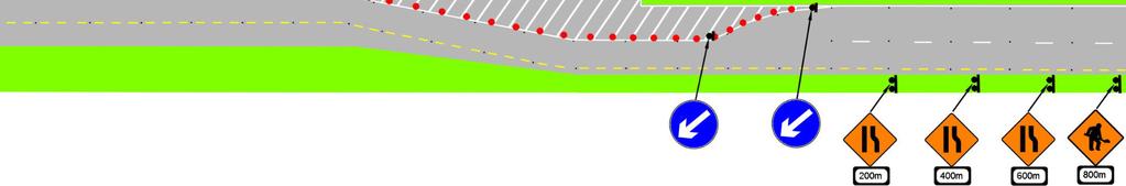
28 The individual elements of this sequence are outlined below. (i) Setting Out Roadworks Ahead Sign (Lane 1/2/etc) Setting-out Roadworks Ahead signs must be provided on Level 3 roads with a speed limit of 80km/h and above to warn road users that a live lane closure is being installed ahead. The Setting-out Roadworks Ahead signs remain in place until the installation is complete and then they are removed. The Setting-out Roadworks Ahead signs must be reinstalled for the removal of the live lane closure. Figure : Setting-Out Roadworks (Lane 1) Figure : Setting-Out Roadworks (Lane 2) For multiple lane dual carriageways and motorways, the Lane 2 Closed (WK 040) sign shown in Figure may be substituted with Lane 3 Closed (WK 042) sign or other appropriate lane closure sign. Mobile VMS may also be used if positioned behind a safety barrier in lieu of a sign. The Setting-Out Roadworks Ahead sign should be placed approximately 500m before the point that TTM operatives cross from / to the hard shoulder to install the first Roadworks Ahead sign in the central median. It can be trailer mounted, or represented on VMS. (ii) Placing Advance Signage Advance signage should be placed on both sides of a Level 3 road as shown below. Figure : Advance Warning Signs (Lane 1 Closure) Rev R11 June 2017 Page 3-24

29 TTM layouts should start in safe locations by avoiding hazardous positions such as close to a curve, slip road, junction or the crest of a hill. They should also ensure there is a minimum clearance of 1.2m between the edge marking of the live lane and where workers are expected to position signs, etc. Signs are placed, beginning with the 1km sign, in sequence towards the works site. Where the TTM will effect a live lane, during the installation operation, a TTM vehicle should be protected with a separate IPV operating m behind it, although this may be relaxed if the TTM will be on the hard shoulder only. Where the central median does not provide a sufficient lateral safety zone ( 1.2m), signs should be installed with the use of an IPV in the outside lane with TTM operatives crossing back to the hard shoulder (with a sufficient lateral safety zone). Alternatively, where crossing the carriageway on foot is not permitted, the TTM vehicle and IPV may be required to install the Advance Signage on the hard shoulder first, before circling back around and installing the signage on the central median. Where this is done all equipment relating to the hard shoulder closure/lane 1 closure is also pre-layed, before circling back around. Where an IPV is used for setting out signs for live lane closures, the Setting-Out Roadworks Ahead sign in Figure must be installed. (iii) Lead-in Tapers The location of a taper is an important component of TTM, as it guides the road user onto the temporary road layout. A lead-in taper should be 180m in length. However subject to a site specific risk assessment, a Designer may specify a longer taper. To ensure road users have enough time to see and react to a lead-in taper, the following rules should be followed: Do not place on tight curve; Do not place over the crest of a hill; and Do not place opposite merges, diverges or junctions or start chicane tapers off the point of a diverge / merge nosing. Generally the start point of tapers are kept 200m away from these locations. There are a number of installation methods that can be adopted, but all will generally involve the use of a TTM operative acting as a traffic hazard spotter working in conjunction with the TTM operative placing the equipment. An IPV should take up position m ahead of the live lane taper start point with the TTM vehicle taking up position at the start of the taper. Rev R11 June 2017 Page 3-25

30 A typical method installs a line of cones behind the TTM vehicle to give the operatives a safe place to work behind. A Keep Left / Right arrow is placed to begin. The TTM vehicle then continues dropping out cones at 3m centres along the inside edge of the closed lane, while walking out a cone from the inside edge to the live lane edge every 18m, again to provide operatives with a safe place to work behind. Once the end of the taper is reached another Keep Left / Right arrow is placed beside the live edge along with any other specified signage. Block lines of cones are placed laterally every 36m along the taper. These are placed from the inside edge, beginning with 1 cone at the very start of the taper and working up to 6 cones at the end of the taper. The outside cone of each block line may be replaced with a heavier traffic delineator panel if required. If night-time TTM is required in unlit areas, steady state lamps should be placed every 6m along the taper. Up to 6 sequential lamps may be placed to run from the start to the end of the taper, normally one at each block line of cones. Where sequential lamps are used, steady state lamps are omitted. Once the taper is installed, the IPV moves onto the hard shoulder, with the TTM vehicle stopped at the end of the taper. Rev R11 June 2017 Page 3-26

 80 100 H/S Width Length (m) (m) 2.5 50 3.0 60 2.5 75 3.0 90 Table 3.3.2.1: Dual Carriageway Hard Shoulder Taper Length Figure 3.")
31 Hard Shoulder Closure A hard shoulder taper is required to close off the hard shoulder on a dual carriageway. Typical lengths of dual carriageway hard shoulder taper lengths are given in Table below. Block lines are not required on a dual carriageway hard shoulder taper. The layout required for a motorway hard shoulder closure is shown in Figure A taper is not required on a motorway. Speed (km/h) H/S Width Length (m) (m) Table : Dual Carriageway Hard Shoulder Taper Length Figure : Dual Carriageway Hard Shoulder Taper Figure : Motorway Hard Shoulder Closure Rev R11 June 2017 Page 3-27
 Dual Carriageway Taper and (b) Motorway Hard Shoulder Closure (iv) Transition Length The transition length is the distance required between the first lead-in taper and the start of the next")
. Where a 7.5 tonne TTM vehicle is used (and to conserve the equipment payload for installing any remaining hard shoulder/lane 1/etc.")
32 Figure : (a) Dual Carriageway Taper and (b) Motorway Hard Shoulder Closure (iv) Transition Length The transition length is the distance required between the first lead-in taper and the start of the next taper (chicane) for the reduction of a number of lanes on multi-lane carriageways. A transition length is needed following each lane closed when two or more lanes are closed on the same carriageway. The transition length should be 360m (twice the taper length). Where a 7.5 tonne TTM vehicle is used (and to conserve the equipment payload for installing any remaining hard shoulder/lane 1/etc. tapers), the TTM vehicle continues to place cones at 12m centres for a further 60m. This is done by either walking them from the inside edge of the closed lane to the live edge or, if there is a coning well on the vehicle, can be dropped directly out along the live edge. The IPV can now pull in front of the TTM vehicle to lay the remaining equipment. Continue placing cones safely along the live edge at 12m centres for the length of the transition and at 6m centres along the live edge for the length of the back wall. Install the back wall by pulling cones from the edge of the live lane into their required positions beginning at the end of the back wall and working towards the start while working within the coned area. Rev R11 June 2017 Page 3-28


33 (v) Multi-Lane Tapers/ Further Transition Lengths Hard Shoulder and Facing Wall Tapers The IPV moves across to take up position m in advance of the start of the hard shoulder taper, followed by the TTM vehicle taking up position at the start of the taper. The TTM vehicle places cones and signs for the full length of the hard shoulder and facing wall taper along the verge. At this point the TTM vehicle will be stopped on the hard shoulder at the end of the facing wall taper, and if required can proceed to park in a safe location. Install the hard shoulder taper under the protection of the IPV. The IPV should now leave the hard shoulder, and may proceed to circle around to provide a rolling block for installing the facing wall taper. As it is not possible to use an IPV to protect the installation of the facing wall, a TTM operative must act as a traffic hazard spotter working in conjunction with the TTM operative placing the equipment. This task must be completed safely, and efficiently. Before proceeding, all cones must be brought to the live edge of the hard shoulder. The TTM operative and their spotter begin pulling the cones out to their required positions beginning at the start of the taper and working towards the end. The final positions of the cones are sighted in before the cones are moved. After 36m of the facing wall has been installed, which includes 1 block line, the IPV may be used to provide a rolling block affording the operatives around 30 seconds to continue to install the taper. Rev R11 June 2017 Page 3-29

34 This is generally referred to as the kick over. Time should not be wasted installing block lines during this period. The length of time achieved is dependent on the transition length. The remainder of the facing wall including block lines can then be installed. Multi-Lane Tapers and Transition Lengths On roads with three or more lanes, where tapers are used in conjunction with transition lengths, the methodology described in placing the lead-in taper may be used. A transition length should be used for Type A works. A direct multi-lane taper should be used for Type B works, therefore a transition length is not required in this scenario. In summary, this means a transition length is not required where the following criteria is met: Works are less than 12 hours duration; The traffic flow will remain less than carriageway capacity (1,200 to 1,300 vehicles / hour per lane left open); and A direct multi-lane taper to the hard shoulder is not permitted. Note: The restriction on one or two items of plant is not applicable on Level 3 roads. (vi) Longitudinal Safety Zone and Works Access The Longitudinal Safety Zone provides a passive safety area for errant vehicles ahead of the works area. It is measured from the end of the taper to the start of the works or the works access, whichever comes first. This must be 45m on an 80km/h road, or 60m on a 120km/h road. Generally 100m is provided if the longitudinal safety zone is to be used immediately ahead of a works access. This area must be kept clear of operatives, plant and materials. Rev R11 June 2017 Page 3-30
 sign or Site Access on Right (WK 053) sign should be installed approximately 100m")


35 Figure : Site Access Installation on a Lane 2 Closure of a 2 Lane Carriageway. Advance warning of a site access should be provided on roads with a speed limit of 80km/h or more. At the appropriate distance after the advance warning of a site access a Site Access On Left (WK 052) sign or Site Access on Right (WK 053) sign should be installed approximately 100m prior to the actual site access. The access point is usually indicated by two to three cones placed close together at an angle or the use of an alternative coloured cone. A flashing lamp may also be used to indicate to road users that this presents a hazard. The gap for the site access is governed by the speed of traffic and size of vehicles required to use it. The gap should be a minimum of 24m but can be extended to 48m. It is not advisable to exceed 48m as this may indicate to other road users that the lane is open. Sufficient room, generally 100m, should be allowed immediately after the site access within the coned area for vehicles entering the works to slow down/stop prior to the works area. Rev R11 June 2017 Page 3-31

36 (vii) Longitudinal Cone Run, Lateral Safety Zone and Signage Through the Site A longitudinal cone run serves as the main dividing line between the live traffic and the work zone. A longitudinal cone run should be installed from a TTM vehicle, preferably with a coning well, or low working platform, so that cones can be placed directly from the vehicle onto their required location, operating within the closed lane up to the end sign locations (initially 20-50m beyond the works exit, to be brought back once the end signage is erected). Required signage through the site is generally placed on the closed lane edge only (where only 1 lane is left open), to reduce the number of crossings required. If it is required to place signage through the site on a narrow median, then the use of a rolling block vehicle should be considered to provide the necessary time to complete the task, or alternative safe method of work used. For extensive linear works such as sweeping, road stud replacement, weed spraying, slot drain cleaning, it may be impractical to install a lateral safety zone for the full length of the works, therefore a risk assessment should be carried out to determine whether a lateral safety zone is required. Figure : Longitudinal Cone Run and Lateral Safety Zone Rev R11 June 2017 Page 3-32

, a rolling road block will be required to install the End sign on the")
 length of longitudinal cones are removed by reversing the TTM vehicle back towards the site while picking up the")
37 (viii) Install Works Exit and Roadworks Ends Signage The Roadworks End Signage should be erected from a point of safety by the extension of the longitudinal cone run described in the previous step. Where the signage needs to be erected on the other side of the carriageway, there needs to be a minimum clearance of 1.2m between the edge marking of the live lane and where workers are expected to position the signs. As such, where there is a no crossings policy, or a narrow central median (on a lane 1 closure), a rolling road block will be required to install the End sign on the other side of the carriageway. After the end signage is complete, the (additional) length of longitudinal cones are removed by reversing the TTM vehicle back towards the site while picking up the cones. The works exit can then be installed at the required location. The layout of the works exit is dependent on the lane being closed. An example is shown for hard shoulder, lane 1 and lane 2. Rev R11 June 2017 Page 3-33

38 (ix) Install Works Area and Internal Layouts To install a lateral safety zone, a second line of cones is dropped out along the length of the works area at a maximum distance of 12m apart. Figure shows an example of where a lateral safety zone is used. To create a physical divide, a safety line of suitable material is installed. The maximum length of continuous safety line is 50m. Double cones are used at these 50m intervals to begin new lengths of safety line. Installing a Diverge Nosing Splitter Installation of a diverge nosing splitter involves an additional hazard of having to place equipment between two live lanes of traffic. The installations need to be timed to comply with the traffic flow requirements described in this document, with crew members being fully briefed on their tasks and clear about what is expected from them, task timings, and the control measures that are going to be used. It is critical that all steps are completed quickly, without the need to rush or panic, and that the crew is protected from live traffic during the installation. Method 1 Method 1 is implemented by extending the line of longitudinal coning past the final location for the splitter, while still allowing a minimum of 100m in advance of the signage vehicle (between the front of the vehicle and the start of the ghost hatching) for traffic to continue to use the diverge. Figure : Installing a Diverge Nosing Splitter Method 1 The crew should erect the diverge splitter behind the vehicle under the protection of the longitudinal cone run. Coning to the front of the traffic management vehicle on both sides to provide a safe area for the next step. (Do not erect the pass either side sign until it is safe for traffic to do so during the next step). Rev R11 June 2017 Page 3-34


39 Figure : Installing a Diverge Nosing Splitter Method 1 Once the splitter is built, the crew can then begin to build the off-ramp taper. They pull the longitudinal cones into the taper from the start of the splitter working backwards, and safely under the protection of the preceding cones, towards the beginning of the final diverge taper. Figure : Installing a Diverge Nosing Splitter Method 1 Rev R11 June 2017 Page 3-35

40 When it is safe to do so, the crew can now cross over to the safe area of the splitter and continue to install the traffic management beyond the exit point. The 100m gap in front of the truck should be closed quickly when there is a gap in traffic. The crew need to be aware that traffic is now passing them on both sides, and in particular not to cross over the diverge without checking it is safe to do so first, when continuing to place cones on diverge hard shoulder. Figure : Installing a Diverge Nosing Splitter Method 1 Final Layout Alternative Method In some locations where there is insufficient length to allow the required distances in front of and behind the traffic management vehicle, or where there are visibility issues for the crew to see oncoming traffic, an alternative method may be required. This method will involve the use of a rolling block vehicle to introduce a working window to allow the crew to place equipment into the off-ramp splitter. With proper planning and sufficient crew, the amount of time required to place the necessary equipment (nosing cones, and splitter sign with sandbags) can be kept as low as one minute, but two additional minutes need to be factored in as a safety measure in calculating the total working window required. The length of the approach section required, where traffic will be under the control of the rolling block vehicle can be estimated from the following table. The rolling block vehicle should preferably travel at 50 km/h and not less than 30 km/h. Rev R11 June 2017 Page 3-36

41 Working Window (minutes) Rolling Block Vehicle Speed 30km/h 50km/h Control Distance (km) Table : Installing a Diverge Nosing Splitter Alternative Method Control Distance The exit taper is established on the hard shoulder side of the off-ramp, and equipment preplaced at the required crossing point in preparation for establishing the splitter. Figure : Installing a Diverge Nosing Splitter Alternative Method The rolling road block is started, communicated and confirmed with the crew with a spotter keeping look out for the point where crew must be off the road (indicated using red arrow in graphic). The spotter should be in direct communication with the rolling block vehicle. The crew place the necessary equipment. Rev R11 June 2017 Page 3-37


42 Figure : Installing a Diverge Nosing Splitter Alternative Method After the rolling road block vehicle has passed, the crew can continue to work behind the newly established off-ramp splitter. The crew need to be aware that traffic is now passing them on both sides, and in particular not to cross over the diverge without checking it is safe to do so first, when continuing to place cones on off-ramp hard shoulder. Figure : Installing a Diverge Nosing Splitter Alternative Method Rev R11 June 2017 Page 3-38

 across the hard shoulder may be used 25m and 50m in advance of the taper to deter drivers from using the hard shoulder. Figure 3.3.3.1: Hard Shoulder Closure on a motorway Rev R11 June 2017 Page 3-39")
43 3.3.3 Traffic Management Installations Hard Shoulder Closure Type A Advance signs must be placed on both sides of the carriageway. The IPV and TTM vehicle then move along the hard shoulder to the start of the taper where the first Directional Arrow is erected and cones are dropped out along the inside of the hard shoulder. Operatives then walk back to the start of the taper and walk each cone out to install the taper and close the hard shoulder. A second Directional Arrow and Lane Closed Board are erected. In addition to the taper, angled lines of cones (3 to 4 cones) across the hard shoulder may be used 25m and 50m in advance of the taper to deter drivers from using the hard shoulder. Figure : Hard Shoulder Closure on a motorway Rev R11 June 2017 Page 3-39

44 Type B Detail permitted layout for short duration works - scaled down static hard shoulder closure with no median signs required. Figure : Hard Shoulder Closure on a motorway with no median signage Type C Type C hard shoulder works are carried out under the protection of an IPV. Rev R11 June 2017 Page 3-40

45 Direct Lane 1 Closure on 2 Lane Carriageways The use of a direct lane 1 closure is subject to the following criteria being met: Traffic flow < 750 vehicles / hour per lane left open; Less than 6 hours duration; and Signage is still required on the verge and the median. Lane 1 Closure Firstly, using an IPV and a TTM vehicle, a lead-in taper, transition length and back wall taper are installed on lane 2. A longitudinal cone run and exit taper are installed to guide the traffic back into the open two lanes. A hard shoulder taper, facing wall, longitudinal safety zone, longitudinal cone run works access and works exit are then installed to complete the lane 1 closure. Refer to Figure In some cases it may be necessary to provide cones along the verge to prevent vehicles from driving into any particular hazards. To close lane 1 on a 3 lane Level 3 road, a merge to the right manoeuvre should be used. Refer to Figure This is only allowed where there are three or more lanes. A similar procedure to that used for a lane 2 closure is used, excluding the installations on lane 2. Figure : Lane 1 Closure on a 2 Lane Motorway Rev R11 June 2017 Page 3-41

46 Figure : Lane 1 Closure on a 3 Lane Motorway Rev R11 June 2017 Page 3-42

47 Lane 2 Closure Using an IPV and TTM, a lead in taper, longitudinal safety zone, works access, longitudinal cone run and exit taper are installed on lane 2. Where possible the hard shoulder should be used to accommodate traffic, but only if sufficient lane width is provided. Figure : Lane 2 Closure on a 2 Lane Carriageway Lane 3 Closure A lane 3 closure on a 3-lane carriageway should follow the principles of a lane 2 closure. Lane 4 Closure A lane 4 closure on a 4-lane carriageway should follow the principles of a lane 2 closure. Rev R11 June 2017 Page 3-43


48 Merges and Diverges Figure : Merge with Works in Lane 2 Figure : Merge with Works in Hard Shoulder Rev R11 June 2017 Page 3-44


49 Figure : Merge with Works in Hard Shoulder and Lane 1 Figure : Diverge with Works in Lane 1 and Hard Shoulder Figure : Works in Hard Shoulder and Lane 1 and longitudinal safety zone beyond Diverge Rev R11 June 2017 Page 3-45


50 Multi-Lane Closures Multi-lane closures are grouped in Type A works and Type B works. Refer to Section for installation method. Type A Works Figure : Lane 2 and 3 Closure on a 3 Lane Carriageway for Type A Works Figure : Lane 1 and 2 Closure on a 3 Lane Carriageway for Type A Works Type B Works A direct multi-lane taper should be used for Type B works, therefore a transition length is not required. This allows the closure of an auxiliary / Lane 1 and also Lane 2 by a direct taper from the hard shoulder without the requirement for transitions. Rev R11 June 2017 Page 3-46

51 Hard Shoulder Running Hard shoulder running is when TTM arrangements are installed to force traffic to run on the hard shoulder for a set length. Without proper planning and site controls there is a higher risk of TTM operatives getting struck due to disorientation and habit of working on the hard shoulder. Before installing, the hard shoulder should be checked for suitability as a running lane. The installation process is different from the standard installation process as the coning layout is completed entirely on the hard shoulder before the lead-in taper/transition length/lane 1 taper is installed. This installation includes the hard shoulder taper, hard shoulder back wall, and hard shoulder re-join taper. Note that block lines of cones are not used on the hard shoulder lead-in taper or re-join taper. The criteria are shown in the table below. Speed (km/h) H/S Width (m) H/S Lead-in Taper Length (m) H/S Re-Join Taper Length (m) Table : Hard Shoulder Running Criteria The lead in taper, transition length and lane 1 taper should then be installed as already described in Section Note that the cones separating the hard shoulder used as a running lane and the closed lane 1 must achieve the required lane widths, and are normally set back from the yellow line marking. Cones are normally used along the verge for the length of the hard shoulder running to protect the drainage channel. These should be spaced at 24m centres. When used, they must be installed immediately adjacent to the asphalt surface during the hard shoulder installation process. It is not permitted to work behind this line of cones. Rev R11 June 2017 Page 3-47


52 Lane Switches during Works Lane switches change the lanes that live traffic use during TTM operations. This operation needs to be well planned and coordinated between the TTM crew and the works crew. Consideration should be given to extending transition lengths at the initial setup to provide for a sufficient window to allow crews to execute the switch. Both crews need to be fully aware of which side of the cones they can work on during each stage of the switch. Layouts must begin with a merge to the left so that advance signage is consistent between switches. TTM operatives should construct the majority of the next phase within the existing closure to minimise the work required when the actual switch occurs. The required sign frames should be erected, but sign faces that could confuse the driver should not be erected until the switch is complete. Likewise, any existing sign faces on display that may confuse the road user should be taken down prior to the switch. To switch between hard shoulder running and lane 1 closure, the layout within the existing lane 1 and 2 closure is set up. A TTM vehicle provides cover under a rolling block for operatives to switch the gate between lane 1 and 2. If additional equipment is needed in the new taper, it can be installed after the gate has been switched. Any work by the works crew should be suspended during this operation. Once the new layout is established, the old TTM layout can be safely removed. The new layout and arrangement should be confirmed between the TTM crew and the works crew, including which side of the cones it is safe to work on. Rev R11 June 2017 Page 3-48


53 Narrow Lane System Works which encroach onto an adjacent lane require a narrow lanes system. This system can be from the verge, from a hard shoulder or from a central median. Advance Warning Signs A narrow lanes system requires advance warning signs which indicate the width of the narrow lanes. These are shown below. Figure : Typical Narrow Lanes System Advance Warning Signs In the above signage, lane 1 should be at the minimum width for all types of vehicles including HGVs but lane 2 at 2.75m would only be suitable for cars and light vehicles. Variations to the above allow for multiple lanes and for lanes that are diverted to the left. Narrow Lanes System Signs through the Works Road users should be informed and reminded of the narrow lane widths throughout the works. The intervals at which signs are repeated should not exceed 1km. Examples of the repeater signs are given below. Figure : Narrow Lanes System Repeater Signs Rev R11 June 2017 Page 3-49

54 The carriageway width displayed should be at least 150mm less than the actual lane width on the narrowest part of the road. Where the road is not straight, this clearance may need to be greater to allow for longer vehicles. Installing a Narrow Lanes System on a 2 Lane Carriageway from Hard Shoulder A hard shoulder running TTM arrangement is temporarily put in place first, closing both lanes 2 and 1. This allows the dashed white line and studs to be removed and orange temporary road markings and studs to be installed at the new lane widths. The location of the lead-in hard shoulder taper for this stage should be selected to correspond with the required position during the narrow lane system. Once the orange temporary road markings and studs are installed, traffic is switched from the hard shoulder into lane 2 using the method described. This allows the orange temporary edge line, temporary vehicle barrier etc. to be installed. Cones can then be pulled back to their required position working from the end of the works through the narrow lane section towards the beginning of the lane 1 narrowing taper. Any temporary vehicle barrier should be installed and set back 500mm from the temporary road marking line in orange and in accordance with manufacturer s specifications. Figure : Narrow Lanes System from Hard Shoulder The 1.6m width as shown above is a combination of a 500mm barrier width and the manufacturer s specifications requiring a 1.1m working width / safety zone. Rev R11 June 2017 Page 3-50

55 Narrow Lanes System on a 2 Lane Carriageway from Central Median Both lane 1 and the hard shoulder are closed first, to allow the orange temporary lining etc. work to be completed on these lanes. A lane switch is then completed between the lane 1 / hard shoulder closure and hard shoulder running. The locations of the hard shoulder back wall and re-join taper should correspond with the required locations during the final narrow lane running. This allows the orange temporary markings, barriers, cones etc to be installed in lane 2. This is completed internally within the lane 1 and 2 closure while the hard shoulder running is in place. The lane 1 and 2 closure can then be removed, while leaving the arrangements for the hard shoulder in place, exposing the newly installed narrow lane system. Figure : Narrow Lanes System from Central Median Rev R11 June 2017 Page 3-51

56 Lane Gain and Lane Drop A lane gain is when the merge runs straight into an additional parallel lane. A lane drop is when the left-most lane diverges off, leaving one less lane on the straight ahead. Where work is being carried out in the lane gain, it is important to close off the hard shoulder prior to installing a temporary acceleration lane. Road users should be given at least 100m warning and the ability to merge with traffic as if they would naturally. Figure : Lane Gain Layout Up and Overs Up and overs is when works are required at a junction overbridge and traffic is diverted from the mainline up onto the diverge and merge and then back onto the mainline. Control may be required at the junction to prevent traffic from queuing down the slip road. Rev R11 June 2017 Page 3-52
57 Figure : Up and Over Layout Rev R11 June 2017 Page 3-53


58 Road Closures A road closure is where the full carriageway is closed for works and road users are diverted from the carriageway, typically via a grade separated junction. Roundabouts Roundabout Installations Figure : Roundabout Installations Rev R11 June 2017 Page 3-54


59 Roundabout Layouts Figure : Works on Exit Lane 2 Figure : Works on Exit Lane 1 Rev R11 June 2017 Page 3-55


60 Figure : Works on Entry Lane 1 Rev R11 June 2017 Page 3-56
61 Working on the Hard Shoulder / Verge If working on the verge, vehicles should be parked off the carriageway completely where this is possible, ensuring there is a route for the vehicle to access the location safely without causing damage to the road assets (including drainage) or environment (eg vegetation). Access by operatives to and from the vehicle also needs to be considered. The parked vehicle should not adversely affect the performance of any safety barrier, including the required working width. Where vehicles cannot be parked off the carriageway, they should be parked on the hard shoulder or at the side of the road in such a way to maximise the lateral clearance between the vehicle and the trafficked carriageway. The desired minimum lateral clearance is 1.5m (1.2m lateral safety zone + 0.3m access width). It is not permitted to reduce this clearance below 0.5m. If required, the verge should be used to maximise this clearance, provided this can be achieved without damaging road assets or the environment. Vehicles parked on the hard shoulder must be liveried with warning beacons in operation, and be visible for minimum of 300m to approaching traffic. If the task will take <15 minutes these controls are sufficient. If the task will take > 15 minutes, then traffic management (hard shoulder closure) will be required to provide a safe area of work. If a series of stops (< 15 minutes) are made on the verge / hard shoulder, in support of activity such as walk through surveys or litter picking, a minimum separation distance of 1.2m must be maintained between personnel and the nearest live lane. This activity requires a risk assessment and appropriate controls need to be selected, including any of the following / or combination of the following: Lane closures, Use of IPV; and Coning along the verge. Rev R11 June 2017 Page 3-57


62 Contra-Flows A contra-flow system creates a sterile area free from traffic in which works may be carried out. It involves creating crossover points and switching traffic onto the opposite carriageway to allow works to be carried out safely. It is essential that appropriate preparation time is allowed for installing a contra-flow system which for major schemes may take up to two weeks. The same preparation time applies to switches and removal. Advance Warning Signs The Advance Warning Signs on approach to the lead in taper should be installed. TTM operatives should install signage to inform road users of the crossover at a distance approximately 200m from the crossover. The signage will depend on the set up being installed. For example, on a 2 lane carriageway where 1 lane is crossed over the One-lane Crossover (Out) (WK 010) sign with supplementary plate 200m should be placed in the transition lane and in the hard shoulder. TTM operatives should repeat this signage at a point close to the crossover. Figure : Standard 2 Lane Carriageway Crossover Signage Repeater signs should be erected at 500m intervals to reinforce the roadworks speed limit if applicable. TTM operatives should install a One-lane Crossover (Back) (WK 011) sign with supplementary plate 200m approximately 200m from the crossover. TTM operatives should install another One-lane Crossover (Back) sign at a point close to the crossover. These should be erected behind the barrier on the central median only. The signs in Figure may also be used where the contra-flow configuration is different to the layout described above. Rev R11 June 2017 Page 3-58


63 Figure : Crossover Signage Buffer Zone A buffer zone is an area provided between two opposing lanes of traffic travelling on the same carriageway at the start and end of a contra-flow operation. This buffer zone should preferably be a lane width but can be reduced to 1.2 or 0.7m. When installing the buffer zone for a contra-flow system on a 2 lane carriageway, traffic needs to be pushed into the hard shoulder to give workers the required 1.2m lateral safety zone. The buffer zone may be constructed using traffic cylinders and temporary road studs. A buffer zone may also be constructed using traffic cones and lamps/reflectors. This method is used where a full lane width is available as shown below. A third type of buffer zone may be constructed using temporary vehicular restraint barriers but the disadvantage of this method is that it may restrict access for the recovery of broken down vehicles. Rev R11 June 2017 Page 3-59


64 Figure : Buffer Zone and Emergency Zone Installing a Contra-flow System on a 2 Lane Carriageway Initially a lane 2 closure is required for both sides of the carriageway. Work should then begin on removing any delineation devices / barriers at the crossover points, such as sections of barrier, wire rope or bollards. The crossover points may require regulating and surfacing to ensure they are suitable for live traffic. TTM operatives should build the tapers for the crossover within the lane closures as shown in in the figure below. Figure : Step 1 - Create Crossover Points Rev R11 June 2017 Page 3-60


65 Step 2 - Switching Traffic Figure : Switch Traffic and install Works Area Completed Contra-flow The completed contra-flow should be as shown in the figure below. Figure : Completed Crossover Wide Loads Provision for wide loads negotiating a contra-flow system should be made. This may include installing Advance Warning Signs to notify road users of wide loads to stop in a designated area until an escort vehicle may be provided to accompany the load through the works. Rev R11 June 2017 Page 3-61


66 and 2+2 Carriageways Advance signage should be placed on a single side of the carriageway as shown in Figure The advance signage and the lane 2 closure should be installed as outlined in Section Signage should not to be placed over the wire rope barrier separating the two carriageways. On roads where drivers transition into a dual carriageway or motorway, drivers should be kept in a single file until they have passed the works area. Drivers can then take advantage of the second lane. Figure (a): Advance Signage on 2+1 Carriageway with Hard Shoulder Figure (b): Advance Signage on 2+1 Carriageway without Hard Shoulder Rev R11 June 2017 Page 3-62

 Transition")

67 Transition to 2+1 from Single Carriageway Figure : Transition to 2+1 from Single Carriageway (Example 1) Figure : Transition to 2+1 from Single Carriageway (Example 2) Transition to 2+2 from Single Carriageway Figure : Transition to 2+2 from Single Carriageway Rev R11 June 2017 Page 3-63
68 3.3.5 Maintenance Regular maintenance should be carried out to ensure the TTM layout continues to function correctly. Refer to Part 0 of these guidance documents for further guidance on TTM maintenance, inspections and audits. Cleaning Signs Sign faces should be cleaned by an operative with another person acting as a spotter. While cleaning signs, operatives should stand in a safe location clear of the live lane. Operatives should not stand on roadside furniture or safety barriers, the use of a long handled brush is recommended to reach large signs. Removal and Replacement of Damaged Equipment Where the TTM layout has been damaged, such as a taper being displaced by an errant vehicle, repairs may need to be carried out under the protection of an IPV. In this case the crew should notify the supervisor immediately to ensure the necessary works are carried out. Maintain Safety Zones The supervisor should ensure the safety zone is: Kept clear of plant; Not used to store materials; Site staff do not cross / lean against barriers; and Vehicles are not parked in the safety zone. Keeping Site Tidy and Running Surfaces Safe Due to the nature of construction work, dust and mud may be generated therefore regular cleaning of cones, signs, reflectors and road surfaces is required, as their reflectivity is greatly reduced by just a thin covering of dust or mud. Particular attention should be given to cleaning reflectors on temporary safety barriers. Also signs and cones can be knocked over or displaced and should be checked regularly and rectified. Rev R11 June 2017 Page 3-64
 sign as shown above should be repeated every 500m through the site. 3.")

69 Emergency Procedures (Recovery) Where a recovery of broken down vehicles service has been provided, the TTM crew should call the contact number in the event of a breakdown. The Free Recovery (WK 096) sign as shown above should be repeated every 500m through the site Removal No graphics required, principles type information Inspections Inspections Regular checks (standard) or as per contract; TTOS to record results in TTM diary. Record Keeping and Incident Reporting In order to keep an up to date record of incidents and TTM activities a site diary must be used. The information recorded in a site diary shall be as follows: What time the installation began; What time the installation was completed; All maintenance activities carried out; Time of any planned switches or modifications to the traffic management; All additional requests from the client; Any incidents or near misses that occurred; What time the removal process began; What time the removal process was completed; and Any issues that arose during the work day. To aid the record keeping of a TTOS, a system of internal reporting of all accidents and incidents of non-compliance with the safety and health management system should be set up within a TTM Crew so that the experience gained may be used to improve the management system. Rev R11 June 2017 Page 3-65
70 Responsibility and Handover between Works Crew and TTM Crew TTM Crew: The TTM crew on site has direct responsibility for implementation, maintenance, modification and removal of TTM arrangements. Works Crew The works crew has responsibility for any other health, safety and other site issues which are not connected to the implementation, maintenance, modification and removal of TTM arrangements. Site Handover/ Induction TTOS to contact Client/Contractor; Agree procedures for maintenance and interim requirements; Agree procedure for removal notification; and Record time of handover in the TTM diary. Audits Audits on Level 3 roads generally only require a drive through to review TTM. A review of dash cam footage may also be used as a means of reviewing the TTM. If an auditor is required to stop within the confines of the TTM, then they should inform the TTOS, obtain relevant site induction(s) and adhere to site rules. They should park their vehicle in a safe secure location where it is not an obstruction or impact on visibility of road users or road workers. They should exit the site as directed by the TTOS and as instructed at the site induction. Rev R11 June 2017 Page 3-66
71 3.4 Mobile Lane Closures Introduction Mobile operations are covered in this section. The purpose is to take the reader from being aware of the requirements of the design standards and layouts within Chapter 8 of the TSM to being able to implement safe operation methods for those layouts. The approach is to give a simple step by step guide complimented with visuals. This gives a quick and easy reference on how to install and remove different mobile operation scenarios. This section includes the following items: Operating Methodologies; Applications of Mobile Operations; Hazard Negotiation; and Verge and Median Works. Rev R11 June 2017 Page 3-67

72 3.4.2 Operating Methodology The operating methodology is summarised as follows: Figure : Mobile Lane Closures Operating Methodology Rev R11 June 2017 Page 3-68
73 Step 1: Equipment Checks Communication Equipment All members of the Mobile Lane Closure and the works vehicle driver must be issued with a communication device. This should be should be through an open channel 2 way radio system. The radio handles that are to be used to identify vehicles should be agreed in advance along with the terminology that will be used to issue instructions. Vehicles and Equipment A walk around check should be completed on each vehicle and trailer to be used during the closure. The trailers need to have the correct signs and the condition of trailer boards and signs need to checked. The use of abrasive weights to secure signs on trailers should be avoided as these tend to damage their surface condition. The operation of the light sensor (to change the light intensity between daylight and darkness) should be checked regularly. The rate of flashing of the 4 folds should also be checked regularly to ensure it is between 60 and 90 flashes per light per minute. IPV The IPV needs to have a minimum 10 tonne on the road weight. In some instances, this may require some equipment to be loaded onto and kept on the IPV during the lane closure. Along with the walk around checks, additional checks should be completed, normally with the aid of an operative in addition to the driver. These include: Lowering and raising the cushion from inside the cab (ensuring it is safe to do so); Checking the rear working lamp, sign, and light arrow; Checking the operation of the beacons; Testing the automatic brake system is functioning correctly; The operation of the light sensor (to change the light intensity between daylight and darkness) should be checked regularly; The rate of flashing of the light arrow should be checked regularly to ensure it is between 30 and 50 flashes per minute with each on period twice as long as the off period; The xenon flashing lamps must only flash on during the light arrows off period; and The in-cab voltage meter for the cushion and lights is checked. It is important that the automatic brake is switched off when travelling above 25 km/h or when crossing lanes on a live carriageway. Rev R11 June 2017 Page 3-69
74 Step 2: Plan the Mobile Operation There should be a clear safe operating procedure for the mobile lane closure. This should cover events that may arise during the mobile lane closure, including where the works vehicle needs to be stationary for 15 minutes, or other approved time. Where a hard shoulder is not available for over 400m, site specific arrangements need to be made. These arrangements may include: A site specific methodology for the mobile closure at that point; Suspension of the mobile lane closure at that point; and Coordination with a static traffic management arrangement at that point. Step 3: Brief TTM and Works Crew The crew need to be aware of the assembly points, start and stop points of the closure and other hazards and controls that are to be used during the closure. The works vehicle must be able to communicate with the mobile closure operation, and must operate between 50m and 100m ahead of the IPV. Where operatives will be on foot ahead of the IPV, they must also work within this distance and should have a Lead Pilot Vehicle ahead of them at a maximum distance of 100m ahead of the IPV. Step 4: Mobile Lane Closure Communication Proper communication is essential for the safe operation of a mobile lance closure. It is important to be clear and concise. During the Mobile Lane Closure radio channels should be kept clear of all communication that is not for the Mobile Lane Closure. Communication is generally passed up and down the line in sequence from the works vehicle/ipv through to trailer 3. As slip roads and hazards are encountered they are communicated backwards beginning with the works vehicle/ipv to trailer 3. Traffic information, such as counts or gaps in traffic are passed forwards beginning with trailer 3 to the works vehicle/ipv. Drivers should confirm that they have heard each communication in sequence. Identifying Location and Maintaining Station It is important when operating a Mobile Lane Closure that the advance warning trailers maintain the correct distance between them. The 1km trailer will normally operate between 900m and 1.1km in advance of the IPV; The 500m trailer will normally operate between 450m and 550m in advance of the IPV; The 250m trailer will normally operate between 225m and 275m in advance of the IPV; and The IPV should normally operate between 50m and 100m in advance of the works. Rev R11 June 2017 Page 3-70
75 These distances may be temporarily changed at locations where there are no hard shoulders, or obstructions such as crash barriers preventing a safe stopping location (subject to a maximum distance of 400m). Inter-visibility between 2 adjacent vehicles is still required in these circumstances. Mobile lane closure vehicle drivers should communicate their position by identifying roadside features such as signage or road markings to the rest of the mobile lane closure team. On roads where chainage markings and plates are present, the chainage markings are the best way of ensuring the vehicles maintain station. When travelling to or from site, signs should not be displayed and vehicle warning beacons should be switched off when driving in normal traffic conditions. The 4 fold lamps should be switched off. On the IPV, the cushion is up, light arrow board lowered, and automatic brake is switched off. (i) Static Signage Erected If required, static signage should be erected in advance of the lane closure and on slip roads. In some cases slip road vehicles, with mobile sign trailers, may be used. This is done under a Type C static operation on the verge/hard shoulder. (ii) Vehicles assemble at designated meeting point Before the lane closure operation begins, vehicles generally meet in advance of the lane closure starting point. This allows final assessment of traffic and conditions to be completed before beginning the closure. This assembly point may be on over/under bridges or roads adjoining the dual carriageway / motorway where there is a safe area for vehicles to park and for crews to exit and enter their vehicles (on the safe side). (iii) Traffic Counts Traffic counts should be carried out before the operation commences and every 15 minutes during the closure. The closure should be removed if: 2 successive counts are above the required level; or The traffic flows counts show a rising trend with the last one above the required level. Permissible 3 Minute Counts 2 lane 3 lane Lane Closure HGV Level If HGV Count HGV Level then Max Traffic Count If HGV Count HGV Level then Max Traffic Count Max HGV Count Permitted Lane Lane Lane Lane Lane Lane Rev R11 June 2017 Page 3-71
76 4 lane Lane Closure HGV Level If HGV Count HGV Level then Max Traffic Count If HGV Count HGV Level then Max Traffic Count Max HGV Count Permitted Lane Lane Lane Lane Table : Mobile Lane Closures - Permissible 3 Minute Counts Note that as HGV content increases, the permitted traffic count decreases. If the HGV count exceeds the permitted level, the closure should also be removed. When performing mobile lane closures on slip roads the maximum traffic count is 25 vehicles / 3 minutes whether it is a single lane or multi-lane slip. Visibility The minimum visibility requirement for a mobile lane closure is 500m, and there must be intervisibility between 2 adjacent vehicles at all times. A mobile lane closure is not a suitable procedure for curvilinear alignments with tight curves. Visibility may be effected by road spray, heavy rain and by a low sun dazzling approaching drivers. (iv) Establishing a Closure There are a number of methods that may be used to establish a closure dependant on site conditions and traffic flows. Broadly they all follow any of 2 outline methods. Signs are not displayed when travelling to or from the starting point. On the IPV, the cushion should be up, light arrow lowered, and automatic brake switched off to begin with. Vehicle warning beacons should only be switched on approximately 400m in advance of pulling into the hard shoulder. Vehicles should indicate they are pulling into the hard shoulder approximately 200m in advance. They should also use their 360 warning beacons when traveling on the hard shoulder and should not use their hazard lights, as this will impair the signalling by their indicators. Lane 1 and the hard shoulder must not be straddled while parked or travelling along the hard shoulder. Drivers should be aware of roadside features, such as filter drains, barriers and soft verges to avoid this occurring. Method 1 All mobile lane closure vehicles park in the hard shoulder in advance of the start of lane closure, normally 2km ahead of this point. The signs are displayed and the 4 fold lamps on the trailers are turned on and the vehicle warning beacons are switched off. The IPV lowers the crash cushion using a safe method, displays the Keep Right arrow, raises and turns on the keep right light arrow. The IPV and works vehicle move into the required lane when it is safe to do so, with the advance trailer vehicles taking up their required position and maintain station. The IPV and works vehicle need to ensure that the correct arrow signs and light arrow Rev R11 June 2017 Page 3-72
77 are displayed at the correct times during this operation. The IPV switches on its automatic braking system and the lane closure commences. Method 2 All vehicles may meet up at a designated assembly point prior to the lane closure. This may be on the hard shoulder, or where a hard shoulder is not available at another suitable point. The advance trailer vehicles take up their required positions at the start of the lane closure. The IPV lowers the crash cushion using a safe method before joining the live lane of traffic along with the works vehicle. The advance vehicle signs are displayed (without turning the 4 folds on, but keeping the vehicle warning beacons on) in advance of the IPV and works vehicle approaching the lane closure. The IPV and works vehicle approach the lane closure in the live lane. On approach, and coordinating via the communication equipment, the advance trailer 4 fold lamps are turned on, and the vehicle warning beacons are switched off. The IPV also raises and turns on the correct light arrow. The IPV and works vehicle move into the lane closure with the flow of traffic and reduce speed to the required amount. The IPV switches on its automatic braking system and the lane closure commences. In all methods, the IPV cannot deploy the cushion in a live lane. The IPV must dominate the lane it is in and not straddle into adjoining lanes, with the exception of a middle IPV within a 3 IPV multi-lane mobile closure. (v) Passing Slip Roads and Hazards If, at any point during a mobile lane closure vehicle comes to a stop and the period of that stop exceeds 20 seconds, the supervisor must be informed immediately and all mobile lane closure vehicles must stop accordingly to maintain the correct distances. Vehicles may stop on the hatched areas present at junctions, provided it is safe to do so. Vehicles communicate that they are approaching and have reached a junction, beginning with the IPV / works vehicle and subsequently each trailer vehicle, while maintaining their station. Vehicles cross over the slip road when it is safe to do so. Each vehicle communicates that they are going to commence and have completed this action. For diverges this is commonly known as jumping off and for merges as jumping on. Compact junctions do not have a hard shoulder for over 400m. This will require a pre-planned method to allow the mobile lane closure to pass it, with all operatives briefed on the method. Where the hard shoulder is blocked, vehicles should move out and around the hazard provided it is safe to do so, and there is a sufficient break in the traffic. Rev R11 June 2017 Page 3-73
78 Working on Slip Roads Where a mobile lane closure is used on slip roads with 2 or more lanes, the trailer vehicle drivers need to replace their distance supplementary plates with on slip sign along with the relevant lane closure sign, while maintaining station. The IPV and works vehicle should ensure that the correct arrow sign and light arrow is displayed. Moving Between Sites When working on separate sites that are 3km apart, the mobile lane closure should be kept in place with vehicles travelling at 20-25km/h to the next work site. When the next work site is > 3km away, the mobile lane closure should be stopped and all signs covered. In this instance vehicles move to the next arranged assembly point, prior to re-establishing a mobile lane closure. (vi) Removing the Lane Closure The IPV switches off the automatic braking system. The IPV and works vehicle move onto the hard shoulder when it is safe to do so. It is important to display the correct arrow sign and light arrow at the correct points during this operation. When the lane closure was in the right lane(s), this may require the IPV and works vehicle to accelerate in the lane and cross when a sufficient gap in traffic appears. The trailer vehicles continue to maintain station during this operation. (vii) Turning Off 4 Folds and Removing Signage When the lane closure is removed, all vehicles should stop on the hard shoulder or alternative safe location. They turn off their 4 folds, remove signage, and turn on their vehicle warning beacons. The IPV can lower it s light arrow and raise it s crash cushion, if it has not already done so, once it is ready to leave site. (viii) Equipment Secured and Transit Away From Site Trailers etc. should be checked and equipment securely stored for transit back to the depot. Using their indicators, vehicles should re-join the traffic, once it is safe to do so, and there is a sufficient break in the traffic. Vehicles should turn off their warning beacons once they have re-joined normal traffic. Vehicle beacons should be kept off when travelling back to the depot in normal traffic. Rev R11 June 2017 Page 3-74


79 3.4.3 Applications of Mobile Operations Hard Shoulder Closures For works carried out in a hard shoulder a roadworks ahead sign accompanied by a supplementary plate advising the public of the distance over which the works will extend must be placed at the beginning of the works. This sign can also be repeated if required. If repeated the distance plate must be accurate. Static signing can be pre-placed over a maximum distance of 10km. Figure : Static Signs for Hard Shoulder Works Hard Shoulder Safety Zone On hard shoulder works where an operative is on foot, the lead pilot vehicle or works vehicle is used to reduce the risk of a vehicle pulling in. Figure : Hard Shoulder Safety Zone Rev R11 June 2017 Page 3-75


80 Mobile Lane 1 Closures Figure : Mobile Lane 1 Closure on a 2 Lane Carriageway Figure : Mobile Lane 1 Closure on a 3 Lane Carriageway Rev R11 June 2017 Page 3-76
81 Mobile Lane 2 / Lane 3 Closures Figure : Mobile Lane 2 Closure on a 2 Lane Carriageway Figure : Mobile Lane 3 Closure on a 3 Lane Carriageway Rev R11 June 2017 Page 3-77

82 Multi-Lane Closures Figure : Mobile Lane 1+2 Closure on a 3 Lane Carriageway Figure : Mobile Lane 2+3 Closure on a 3 Lane Carriageway Rev R11 June 2017 Page 3-78


83 Slip Roads Works Diverge slip roads may be signed as shown below. A Roadworks End sign should be placed on the verge for road users exiting the main carriageway. Figure : Diverge Slip Road Negotiation Mobile Signage Merge slip roads should be signed as shown in the figures below. A Roadworks Ahead sign accompanied by a supplementary plate advising the public of the works taking place ahead shall be installed on the verge side for motorists entering the carriageway via the merge slip road. Figure : Merge Slip Roads Negotiation Static Signage The use of a slip road vehicle is also an option. When using a slip road vehicle there is no end sign placed on the diverge slip road. The slip road vehicle is in place just prior to the MLC train reaching the slip road and is removed just after the MLC train has passed. The operation remains entirely mobile with no static signs. Rev R11 June 2017 Page 3-79
84 Figure : Merge Slip Road Negotiation Mobile Signage Rev R11 June 2017 Page 3-80
85 Rolling Road Block Planning Establish the duration of the working window needed to complete the task. The working window should compromise of the time required to complete the task plus a safety margin of 2 minutes. In general the working window, including the safety margin should not exceed 7 minutes. The presence of any merge/diverge, lane gain, or lane drops in the length of the carriageway between the works area and the closure start point should be identified. The table below shows the distance upstream of the works area that the closure must start in order to provide the required working window, for closure speeds of 30km/h and 50km/h. The figures include an allowance of 2km for the closure vehicles to move into the required lanes safely and establish a rolling road block. Required Duration of Working Window (Minutes) Closure Start Point - Upstream of the Works Area (km) Closure Speed 30km/h 50km/h Table : Rolling Road Block Closures Below is an example of how vehicles used for a rolling road block should be positioned and how the table above is used to determine the correct distance prior to the works. The example used is for a 4 minute working window at 30km/h which results in a required distance prior to the works that the closure should start is 5.6km. Rev R11 June 2017 Page 3-81


86 Figure : Rolling Road Block Vehicle Positions Rolling Road Block Operation Sequence The IPV and works vehicle should be positioned on the hard shoulder as shown below. Figure : Rolling Road Block - IPV and Works Vehicle on Hard Shoulder Before the RRB commences the closure vehicles, advance warning vehicles and monitor vehicle should assemble in a safe place off the carriageway for final checks and briefing. The advance vehicles and monitor vehicles will then proceed to the agreed location. The TTOS then instructs the monitor vehicle driver to perform a traffic count (<60 veh/3 mins required to proceed) Monitor vehicle drives behind slowest moving vehicle and verifies it is travelling >80km/h. If speed is <80 km/h, the operation cannot proceed. Once the supervisor is satisfied that the operation can proceed he/she should inform the closure vehicles. The IPVs manoeuvre within normal traffic flow conditions to align laterally across the carriageway. Rev R11 June 2017 Page 3-82


87 Figure : Start of Closure Procedure Their speed is then gradually reduced to a pre-determined speed (usually 30-50km/h), slowing the traffic behind them. This creates a traffic free zone between the IPVs and the traffic in front of them. Figure : Start of Working Window The IPV s and traffic gradually come to a stop before the works area. Figure : End of Working Window Closing Merge Slip Roads When implementing a RRB, merge slip roads shall be securely closed for a brief period during the operation to prevent traffic entering the traffic free zone ahead of the closure vehicles. The slip road is closed just before the monitor vehicle passes and is re-opened again when the closure vehicles have passed. There is no Managers Order required for a slip road closure providing it is under 10 minutes duration. The length of the slip road, available sight lines, and the anticipated traffic flow need to be taken into account. This will help determine the methodology used to close the slip road. There are two methods for closing a slip road. The first option uses a number of advance static road signs, stop and go battens and an IPV. This operation is shown below. Rev R11 June 2017 Page 3-83

88 Figure : Merge Closure Option 1 The second method uses static traffic management equipment to close the slip road at its entry. Figure : Merge Closure Option 2 Where a MLC is required to close two lanes of a multiple lane carriageway, three number IPVs are required. The vehicles should be positioned 50m apart with the middle vehicle straddling the lane line to prevent road users driving between the other IPV s as shown below. Rev R11 June 2017 Page 3-84


89 Figure : Positioning IPVs to prevent road users driving between the other IPVs example shows a lane 2 and 3 closure Figure : Positioning IPVs to prevent road users driving between the other IPVs example shows a lane 1 closure Rev R11 June 2017 Page 3-85

90 3.4.4 Hazard Negotiation Slip Road Negotiation The following procedure should be followed where a MLC on the mainline passes entry or exit slip roads. Static or mobile advance warning signs must be installed on all entry slip roads. As the MLC vehicles approach the point where the slip road is to be crossed, the driver should make the necessary observations to ensure that it is safe to pass the slip road. If a vehicle within the MLC crew comes to a stop for 20 seconds or more, the TTOS must be informed immediately and all other vehicles should be stopped accordingly to maintain the correct distances. Figure : Slip Road Negotiation Works on a Two Lane Slip Road When working on slip roads the maximum allowable traffic flow is 25 vehicles / 3 minutes. When working is taking place coming up to a slip road the signage on the rear of the trailers is showing the work in lane 1 of the main carriageway. The operatives in that trailer should remove the distance supplementary plate and replace it with an On Slip Road sign. An example of this operation is shown below. Rev R11 June 2017 Page 3-86


91 Figure : Two Lane Slip Road Negotiation Passing Obstacles Where there is an obstacle in a hard shoulder, the IPV driver should communicate the details of the hazard to the other drivers. Trailer 1 then comes to a stop and informs the drivers of the other advance warning sign vehicles to maintain their positions. The procedure for passing the hazard is the same as for negotiating slip roads. When the hazard has been successfully passed, Trailer 1 should inform the other advance warning sign vehicles drivers and Trailer 2 and 3 can now move up to their correct station. This procedure is repeated for the other trailer drivers. Figure : Passing Obstacles Rev R11 June 2017 Page 3-87


92 Compact Junction Negotiation Compact Junctions like the one illustrated below generally have no hard shoulder between the merge and diverge slip roads. Negotiating these junctions can be tricky due to the distance the AWS trailer vehicles have to negotiate in the live traffic lane. Figure : Two Lane Slip Road Negotiation Operations where Hard Shoulder is not present Figure : Operations where a Hard Shoulder is not present Rev R11 June 2017 Page 3-88
Chapter 8 (2009) - Summary of key changes
 - Summary of key changes") Chapter 8 (2009) - Summary of key changes (Some sections and paragraphs in the revised edition have been renumbered to take account of new sections and paragraphs; section numbers below refer to the revised
Chapter 8 (2009) - Summary of key changes (Some sections and paragraphs in the revised edition have been renumbered to take account of new sections and paragraphs; section numbers below refer to the revised
Essential Standard No. 16. Streetworks - Short duration static works carried out from a vehicle
 Key Messages Short duration static works must not exceed 60 mins, including setting up and dismantling traffic management. A vehicle or vehicles should be used whenever possible to protect the workforce.
Temporary Vehicle Restraint System Policy
 Temporary Vehicle Restraint System Policy Prepared By; J Wilkinson H&S Manager, Civils Prepared for: Installation of TVRS on all triio highways projects including JV s. Page 1 of 8 Contents 1.0 Introduction
Developed by: The American Traffic Safety Services Association (ATSSA) 15 Riverside Parkway, Suite 100 Fredericksburg, VA
 15 Riverside Parkway, Suite 100 Fredericksburg, VA") Addendum Developed by: The American Traffic Safety Services Association (ATSSA) 15 Riverside Parkway, Suite 100 Fredericksburg, VA 22406-1022 800-272-8772 This material is based upon work supported by
Addendum Developed by: The American Traffic Safety Services Association (ATSSA) 15 Riverside Parkway, Suite 100 Fredericksburg, VA 22406-1022 800-272-8772 This material is based upon work supported by
Appendix Work Zone Traffic Control
 ppendix Work Zone Traffic Control The purpose of this appendix is to present basic guidelines for work zone traffic control and to supplement the Highway Work Zone Safety Checklist. This appendix presents
Temporary Traffic Management
 Draft June 2017 www.dttas.ie Operation Guidance Temporary Traffic Management [Blank Page] Temporary Traffic Management Operation Guidance REVISION CONTROL Revision First Draft Title Temporary Traffic Management
WORK ZONE TRAFFIC CONTROL PROCEDURES
 WORK ZONE SETUP / REMOVAL WORK ZONE TRAFFIC CONTROL PROCEDURES When installing a work zone, install the advance warning signs on all approaches prior to installing the traffic control devices. Perform
Generic Safe Method for placing TTM on MM-ALR
 Summary 1. This paper describes a generic safe method for setting up and taking down Temporary Traffic Management (TTM) on Managed Motorway All Lane Running (MM-ALR) schemes. 2. An understanding of how
GUIDELINES FOR EMERGENCY TRAFFIC CONTROL
 GUIDELINES FOR EMERGENCY TRAFFIC CONTROL TABLE OF Contents Page Introduction...1 Chapter 6I of the 2009 MUTCD...2 Reason for Control...6 Components of Incident Management Area...7 Traffic Control Devices
DEFINITIONS Activity Area - Advance Warning Area Advance Warning Sign Spacing Advisory Speed Approach Sight Distance Attended Work Space
 DEFINITIONS Activity Area - that part of a TTC zone activity area where the work actually takes place. It consists of the work space, traffic space and one or more buffer spaces. Advance Warning Area -
SECTION 12 ROAD MARKINGS AND DELINEATION
 SECTION 12 ROAD MARKINGS AND DELINEATION (Blank Page) MANUAL OF TRAFFIC SIGNS AND MARKINGS - Part III: Motorways and Expressways 12-1 12.1 GENERAL 12.1.1 INTRODUCTION The markings and delineation details
CHAPTER 6H. TYPICAL APPLICATIONS
 2006 Edition Page 6H-1 CHAPTER 6H. TYPICAL APPLICATIONS Section 6H.01 Typical Applications Support: Whenever the acronym TTC is used in this Chapter, it refers to temporary traffic control. Standard: The
DRAFT INTERIM ADVICE NOTE 150/17
 DRAFT INTERIM ADVICE NOTE 150/17 Guidance on Alternative Temporary Traffic Management Techniques for Relaxation Works on Dual Carriageways Summary Guidance for temporary traffic management (TTM), on the
Q&A for Safety Code. Prepared by the HAUC-UK Safety Code working group
 Q&A for Safety Code Prepared by the HAUC-UK Safety Code working group 1 What is the latest version of the Safety Code? At the time of writing, the last time any amendments were made to the Safety Code
INTERIM ADVICE NOTE 188/16
 INTERIM ADVICE NOTE 188/16 Guidance on Omission of Warning Lights (Road Danger Lamps) for Relaxation Works on Dual Carriageways Summary Guidance for omission of warning lights (road danger lamps) in temporary
SECTION 12 ROAD MARKINGS AND DELINEATION
 SECTION 12 20 June 2009 Part 3: Motorways and Expressways CONTENTS Reference Page Page Number Date SECTION 12: MARKINGS AND DELINEATION 12.1 GENERAL... 12-1 June 2009 12.1.1 INTRODUCTION... 12-1 June 2009
Including Revision 1 dated May 2012 and Revision 2 dated May 2012
 Including Revision 1 dated May 2012 and Revision 2 dated May 2012 Page 634 2009 Edition Notes for Figure 6H-1 Typical pplication 1 Work eyond the Shoulder 1. If the work space is in the median of a divided
TRAFFIC ACCOMMODATION IN WORK AREAS
 TRAFFIC ACCOMMODATION IN WORK AREAS TRAFFIC ACCOMMODATION IN WORK AREAS Copyright 2005 All rights reserved. Reproduction of this document in whole or in part by any means is prohibited, unless authorized
TRAFFIC CONTROL DEVICES
 TRAFFIC CONTROL DEVICES SIGNS Temporary traffic control work zone signs include regulatory, warning and guide signs utilized to provide regulations, warnings and guidance information to road users impacted
INTERSECTIONS AT GRADE INTERSECTIONS
 INTERSECTIONS 1 AT GRADE INTERSECTIONS INTERSECTIONS INTERSECTIONS = INTERRUPTED FACILITIES Definitions and key elements An intersection is defined as an area where two or more roadways join or cross.
INTERIM ADVICE NOTE 150/14 Revision 02. Guidance on Alternative Temporary Traffic Management Techniques for Relaxation Works on Dual Carriageways
 INTERIM ADVICE NOTE 150/14 Revision 02 Guidance on Alternative Temporary Traffic Management Techniques for Relaxation Works on Dual Carriageways Summary Guidance for temporary traffic management (TTM),
TRAFFIC CONTROL DEVICES MANUAL FOR WORK ZONES
 TRAFFIC CONTROL DEVICES MANUAL FOR WORK ZONES SUMMARY Flagpersons play an important role in the high level of traffic safety expected through work zones on Saskatchewan highway projects. Flagpersons are
Q&A for Safety Code. Prepared by the HAUC-UK Safety Code working group
 Q&A for Safety Code Prepared by the HAUC-UK Safety Code working group 1 What is the latest version of the Safety Code? At the time of writing, the last time any amendments were made to the Safety Code
RAILWAY LEVEL CROSSING CHECKLIST Road Safety Review of Railway Crossings
 RAILWAY LEVEL CROSSING CHECKLIST Road Safety Review of Railway Crossings Location: Crossing No. Date of On-Site Inspection: (Day) / / (Night) / / Weather: CHECKLIST 5. - GENERAL TOPICS Level of control
MUTCD Part 6G: Type of Temporary Traffic Control Zone Activities
 MUTCD Part 6G: Type of Temporary Traffic Control Zone Activities 6G.01 Typical Applications Each temporary traffic control (TTC) zone is different. Many variables, such as location of work, highway type,
CIRCULAR NO. O-13. Recommended Practices for Manual Protection of Highway/Railway Grade Crossings
 CIRCULAR NO. O-13 Recommended Practices for Manual Protection of Highway/Railway Grade Crossings Effective: October 1, 2004 CONTENTS 1. SCOPE 2. GENERAL PRINCIPLES 3. DEFINITIONS 4. PROTECTION REQUIRED
Traffic Control & Road Closures for Special Events
 Traffic Control & Road Closures for Special Events Application for Road Closures: Street closures and/or detours may be required for special events/parades. Approval shall be obtained from the Roads Operations
2009 Manual on Uniform Traffic Control Devices
 2009 Manual on Uniform Traffic Control Devices Tori Brinkly, PE Highway Safety Engineer WFL-FHWA April 20, 2010 Paragraphs are numbered. Standard Statements are bolded. Guidance statements are italicized.
CHAPTER 6H. TYPICAL APPLICATIONS
 Section 6H.01 Typical Applications Support: CHAPTER 6H. TYPICAL APPLICATIONS Chapter 6G contains discussions of typical temporary traffic control activities. Chapter 6H presents typical applications for
CHECKLIST 5: ROADWORK TRAFFIC SCHEME AUDIT
 CHECKLIST 5: ROADWORK TRAFFIC SCHEME AUDIT 5.1 General items 5.1.1 Alignment Are the roadworks located safely with respect to horizontal and vertical alignment? If not, does works signing cater for this?
Emergency Roadside Technician Dies When Struck by a Single-Unit Truck on an Interstate Shoulder. Incident Number: 05KY001
 Emergency Roadside Technician Dies When Struck by a Single-Unit Truck on an Interstate Shoulder Incident Number: 05KY001 Location on bridge where responder attempted to avoid semi. Kentucky Fatality Assessment
Proposed: Temporary Traffic Management Design Guidance
 Current Temporary Traffic Management Guidance Structure: Chapter 8 Traffic Signs Manual First published in 1996, updated 2007 Addendum in 2010 Guidance for the Control and Management of Traffic at Road
CONSTRUCTION SPECIFICATION
 CAPRICORN MUNICIPAL DEVELOPMENT GUIDELINES CONTROL OF TRAFFIC C201 CONSTRUCTION SPECIFICATION CAPRICORN MUNICIPAL DEVELOPMENT GUIDELINES C201 ISSUE: NO:1 October 2007 TABLE OF CONTENTS CLAUSE CONTENTS
CHECKLIST 2: PRELIMINARY DESIGN STAGE AUDIT
 CHECKLIST 2: PRELIMINARY DESIGN STAGE AUDIT 2.1 General topics 2.1.1 Changes since previous audit Do the conditions for which the scheme was originally designed still apply? (for example, no changes to
TRAFFIC CONTROL DEVICES MANUAL FOR WORK ZONES
 TRAFFIC CONTROL DEVICES MANUAL FOR WORK ZONES APPLICATION Delineation devices are used to warn and alert motorists of hazards created by work activities in or near the travelled way and to guide and direct
CW20-1D 48" X 48" (Flags- See note 1) G " X 24" (See note 2)
 G X 24 (See note 2)") CK: DW: CK: x for mph or less mph devices may be omitted if the work area is a minimum of from the nearest traveled way. (See notes 4 & 5) x for mph or less Work Space mph x for mph or less mph (See notes
CK: DW: CK: x for mph or less mph devices may be omitted if the work area is a minimum of from the nearest traveled way. (See notes 4 & 5) x for mph or less Work Space mph x for mph or less mph (See notes
Use of High Level Signs for Static Relaxation Works
 Transport Research Laboratory Use of High Level Signs for Static Relaxation Works by R Wood, M Palmer, C Reeves, I Rillie RPN2084 PSF E158 DRAFT PROJECT REPORT Transport Research Laboratory DRAFT PROJECT
SARF Engineering for Road Safety
 SARF Engineering for Road Safety 1 Road Traffic Signs Manual & Legislation National Road Traffic Act, Act 93 of 1996 National Regulations 2000 SADC and SA Road Traffic Signs Manuals No. Title SADCRTSM
Road Safety Audit training course. Motorways - safety issues of the motorway design
 Road Safety Audit training course Motorways - safety issues of the motorway design Jesper Mertner, Road safety auditor, COWI A/S 1 ROAD SAFETY AUDITING COURSE Content 1. Safety 2. Cross sections 3. Horizontal
Appendix C. TRAFFIC CALMING PROGRAM TOOLBOX
 Appendix C. TRAFFIC CALMING PROGRAM TOOLBOX PHASE I...2 Do Not Enter Sign...3 One-Way Sign...4 Turn Prohibition...5 Pavement Markings...6 Speed Monitoring Trailer...7 Neighborhood Speed Watch...8 Police
Q&A for Safety Code. Prepared by the HAUC-UK Safety Code working group
 Q&A for Safety Code Prepared by the HAUC-UK Safety Code working group Q1 What is the latest version of the Safety Code? The last time any amendments were made to the Safety Code was in June 2014. This
STREET and UTILITY REPAIRS WORK AREA PROTECTION GUIDE
 STREET and UTILITY REPAIRS WORK AREA PROTECTION GUIDE May 2006 Street and Utility Repairs Work Area Protection Guide TABLE OF CONTENTS 1. Introduction... 1 2. Typical Applications... 11 2.1 Use of Hand-Signaling
Safe Working On Roads Standard Operating Procedures
 Safe Working On Roads Standard Operating Procedures Operational Management Procedures Page 1 of 15 Safe Working on Roads SOPs Prepared by State Operations NSW Rural Fire Service 15 Carter Street, Lidcombe
Design Measures taken, or being taken to eliminate or reduce the hazard
 Part B: CDM 2007 MMFD Procedures Hazard Elimination and Management Schedule Project Title: Managed Motorways All Lanes Running (MM-ALR) Job No.: 1039092 Design Discipline: IAN161/12 Prepared By: Emma Clutterbuck
INTERIM ADVICE NOTE 150/12. Guidance for Alternative Temporary Traffic Management Techniques for Relaxation Schemes on Dual Carriageways.
 INTERIM ADVICE NOTE 150/12 Guidance for Alternative Temporary Traffic Management Techniques for Relaxation Schemes on Dual Carriageways Summary Guidance for temporary traffic management (TTM), on the approach
Introduction Methodology Study area and data collection Results and recommendation Conclusion References
 Introduction Methodology Study area and data collection Results and recommendation Conclusion References It is formal procedure for assessing accident potential and safety performance in the provision
MANUAL OF TEMPORARY TRAFFIC CONTROL ON CITY STREETS
 MANUAL OF TEMPORARY TRAFFIC CONTROL ON CITY STREETS PUBLIC WORKS DEPARTMENT 2015 REVISION 1-2016 REVISION SUMMARY - MARCH 2016 Introduction 1.05 - Specifications for Traffic Control Devices Temporary Traffic
CHECKLIST 6: EXISTING ROADS: ROAD SAFETY AUDIT
 CHECKLIST 6: EXISTING ROADS: ROAD SAFETY AUDIT 6.1 Road alignment and cross-section 6.1.1 Visibility; sight distance Is sight distance adequate for the speed of traffic using the route? Is adequate sight
// RoWSaF Making roads safer for road workers rowsaf.org.uk. RoWSaF Strategy 2015
 // RoWSaF Making roads safer for road workers rowsaf.org.uk Working in partnership with clients, industry and key stakeholders to improve worker safety Often working close to live traffic, activities conducted
2017 Changes to the 2011 MMUTCD January 2017
 2017 Changes to the 2011 MMUTCD January 2017 The design for the Weight Limit symbol sign (R12-5) has been modified to show a threeunit vehicle as the third line of the regulatory weight limit sign. This
Pass your Driving Test with confidence
 Pass your Driving Test with confidence Sample theory questions, and answers to help you prepare for your driving test. Q1. When should you not drive? While under the influence of alcohol, drugs (prescribed
Temporary Traffic Control for Highway Work Zones
 Temporary Traffic Control for Highway Work Zones MONTHLY DELMARVA MISS UTILITY MEMBER MEETING MARCH 20, 2014 PRESENTED BY: Adam Weiser, P.E. PTOE Safety Programs Manager Delaware Department of Transportation
Printed copies of this document may not be current. Refer to SafetyNet (Domino.Doc) for the official, controlled version.
 for the official, controlled version.") SASKPOWER TRAFFIC CONTROL PLANNING GUIDELINES INTRODUCTION page 3 DEFINITIONS page 3 PLANNING AND PREPARATION page 6 Pedestrian Safety within an Active Work Area page 7 Excavations page 8 Partial Lane
SASKPOWER TRAFFIC CONTROL PLANNING GUIDELINES INTRODUCTION page 3 DEFINITIONS page 3 PLANNING AND PREPARATION page 6 Pedestrian Safety within an Active Work Area page 7 Excavations page 8 Partial Lane
Regulatory traffic signs
 Section 21: Regulatory traffic signs This section includes the signs that show a road regulation is in place. These must be obeyed. Regulatory signs show the course a driver must follow and an action they
MINNESOTA FLAGGING HANDBOOK
 MINNESOTA FLAGGING HANDBOOK January, 2018 Flagging Handbook This Flagging Handbook has been developed following the guidelines of the 2011 edition of the Minnesota Manual on Uniform Traffic Control Devices,
Traffic signs used, including signs giving orders, warning signs, direction signs, information signs and road works signs.
 Traffic signs Traffic signs used, including signs giving orders, warning signs, direction signs, information signs and road works signs. Although The Highway Code shows many of the signs commonly in use,
Supplementary Appendix to ARTC Track & Civil Code of Practice. Establishing Minimum Protective Measures at Level Crossings ETF-16-01
 Discipline Engineering Specification Category Supplementary Appendix to ARTC Code of Practice Establishing Minimum Protective Measures at Level Crossings Applicability ARTC Network wide New South Wales
Traffic Control Inspection Checklist Segment:
 Traffic Control Inspection Checklist Segment: Simon Contractors Simon Contractors Originator: Description Reviewed by: Initials Date Distribution: Traffic Quality Manager, Site Assistant Traffic Manager
CHAPTER 1 STANDARD PRACTICES
 CHAPTER 1 STANDARD PRACTICES OBJECTIVES 1) Functions and Limitations 2) Standardization of Application 3) Materials 4) Colors 5) Widths and Patterns of Longitudinal Pavement Marking Lines 6) General Principles
Signs. signs, signals and road markings. in this chapter
 3 signs, signals and road markings in this chapter Signs regulatory signs school, playground and crosswalk signs lane use signs turn control signs parking signs reserved lane signs warning signs object
Interim Advice Note 115/08, Revision 1. Requirements and Guidance for Works on the Hard Shoulder and Road Side Verges on High Speed Dual Carriageways
 Interim Advice Note 115/08,. Requirements and Guidance for Works on the Hard Shoulder and Road Side Verges on High Speed Dual Carriageways Summary Requirements and guidance for works on the hard shoulder
Aiming for Zero Road Worker Safety. Mark Pooley Highways Agency Road Worker Safety Programme Manager Monday 11 June 2012
 Aiming for Zero Road Worker Safety Mark Pooley Highways Agency Road Worker Safety Programme Manager Monday 11 June 2012 1. Road Worker Safety Strategy. RWS Strategic Target No. 1: achieve a substantial
Section 3A.04 Colors. Section 3B.10 Approach Markings for Obstructions
 Section 3A.04 Colors Markings shall be yellow, white, red, or blue, or purple. The colors for markings shall conform to the standard highway colors. Black in conjunction with one of the above colors shall
Work Zone Traffic Safety
 Work Zone Traffic Safety Summary The Hazard: death or serious injury from being struck by vehicles or equipment in work zones. Who is at risk: streets/highways, utilities and other public works department
Draft letter to Designers and Managing Agents INTERIM ADVICE NOTE 43/02: CANTILEVER AND PORTAL GANTRY VMS
 Draft letter to Designers and Managing Agents INTERIM ADVICE NOTE 43/02: CANTILEVER AND PORTAL GANTRY VMS This Interim Advice Note announces amendments to a series of guidelines related to cantilever and
Traffic Signs and Signals
 CHAPTER FOUR Traffic Signs and Signals Traffic signs control traffic flow, making streets and highways safer for drivers, bicyclists and pedestrians. These signs, which are posted by the Indiana Department
REVOCABLE PERMIT FOR STREET BANNER APPLICATION PACKAGE
 Development Engineering 300 Richards Blvd., 3rd Floor Sacramento, CA 95811 Engineering Services Division REVOCABLE PERMIT FOR STREET BANNER APPLICATION PACKAGE Phone: 916-808-8300 Fax: 916-808-1984 Preparation
Road Markings. Lecture Notes in Transportation Systems Engineering. Prof. Tom V. Mathew
 Road Markings Lecture Notes in Transportation Systems Engineering Prof. Tom V. Mathew 1 Overview The essential purpose of road markings is to guide and control traffic on a highway. They supplement the
PLACEMENT OF SIGNS RECOMMENDED PRACTICES SUB-SECTION
 Page 1 of 6 RECOMMENDED PRACTICES PART SECTION SUB-SECTION HIGHWAY SIGNS GENERAL General Proper positioning of signs is an important element in the overall control of traffic within a roadway network.
New Trends In Temporary Traffic Control (TTC) Spring Occupational Safety & Health Committee Conference Philadelphia, PA
 Spring Occupational Safety & Health Committee Conference Philadelphia, PA") New Trends In Temporary Traffic Control (TTC) Spring Occupational Safety & Health Committee Conference Philadelphia, PA Michael Kelly Work history - Fire service member of 30 years (retired at the rank
New Trends In Temporary Traffic Control (TTC) Spring Occupational Safety & Health Committee Conference Philadelphia, PA Michael Kelly Work history - Fire service member of 30 years (retired at the rank
Technical note - Level 2 low speed (2LS) roads. Document name. Issued: 3 June 2016 Effective: 1 August 2016
 roads. Document name. Issued: 3 June 2016 Effective: 1 August 2016") Technical note - Level 2 low speed (2LS) roads Document name Issued: 3 June 2016 Effective: 1 August 2016 Page 1 Introduction of 2LS roads The mandate for change At the 1 October 2014 meeting of the CoPTTM
Technical note - Level 2 low speed (2LS) roads Document name Issued: 3 June 2016 Effective: 1 August 2016 Page 1 Introduction of 2LS roads The mandate for change At the 1 October 2014 meeting of the CoPTTM
Plan prepared for: Brennan Paving and Construction. Plan prepared by: Direct Traffic Management
 Traffic Control Plan Hwy 401 - Bridgeland Avenue / Site 37-283 Grading, Drainage, Garnular Base, Hot Mix Paving, Electrical, Structural and Plan prepared for: Plan prepared by: General Notes WB 401 Collector
Improving the Visibility of Manual Traffic Controllers Trials 2016
 ` Improving the Visibility of Manual Traffic Controllers Trials 2016 ` Improving the Visibility of Manual Traffic Controllers Trials 2016 Prepared By Jeff Kaye Fulton Hogan National Safety Training Manager
SLOUGH Stage 3 Road Safety Audit of A4 London Road, M4 J5 to Sutton Lane
 SLOUGH Stage 3 Road Safety Audit of A4 London Road, M4 J5 to Sutton Lane Exception Report Client Officer Rudo Beremauro Date 20 January 2015 RSA /Project Sponsor s Contents Section 3 Project Sponsor's
MANUAL OF TRAFFIC SIGNS AND MARKINGS SECTION 2
 MANUAL OF TRAFFIC SIGNS AND MARKINGS PART 1 SIGNS SECTION 2 September 2015 VERSION 1.0 - DRAFT FOR REVIEW Part 1 Signs REGULATORY SIGNS GENERAL CONTENTS SECTION 2: REGULATORY SIGNS GENERAL (DESIGN, POLICY
CHAPTER 2G. PREFERENTIAL AND MANAGED LANE SIGNS
 2011 Edition - Revision 2 Page 275 Section 2G.01 Scope CHAPTER 2G. PREFERENTIAL AND MANAGED LANE SIGNS 01 Preferential lanes are lanes designated for special traffic uses such as high-occupancy vehicles
Road Markings. Lecture Notes in Transportation Systems Engineering. Prof. Tom V. Mathew. 1 Overview 1. 2 Classification 2
 Road Markings Lecture Notes in Transportation Systems Engineering Prof. Tom V. Mathew Contents 1 Overview 1 2 Classification 2 3 Longitudinal markings 2 3.1 Center line.....................................
NOT TO SCALE PUBLIC WORKS STANDARD DETAILS CURB DETAILS DATE: MARCH 2013 FILE NAME: CURB.DWG
 NOT TO SCALE PUBLIC WORKS STANDARD DETAILS CURB DETAILS DATE: MARCH 2013 FILE NAME: CURB.DWG NOT TO SCALE PUBLIC WORKS STANDARD DETAILS SIDEWALK RAMPS DATE: MARCH 2013 FILE NAME: SIDEWALK RAMPS.DWG NOT
WORK ZONE TRAFFIC CONTROL & SAFETY
 WORK ZONE TRAFFIC CONTROL & SAFETY Purpose of Temporary Traffic Control 1. Warn motorists and pedestrians of hazards. 2. Advise proper travel path. 3. Delineate areas not to be used. 4. Separate the travel
MEWP - Boom Note: It is recommended that you read the Supporting Information page before you read this factsheet.
 MEWP - Boom Note: It is recommended that you read the Supporting Information page before you read this factsheet. Preparation for work (Preparation) Boom-type mobile elevated work platforms, commonly known
2C-3 Placement of Warning Signs
 C. WARNING SIGNS 2C-1 Application of Warning Signs Warning signs are used when it is deemed necessary to warn traffic of existing or potentially hazardous conditions on or adjacent to a highway or street.
STATE OF MARYLAND FLAGGER EXAM
 GRADE: NAME (PRINT): ADDRESS: CITY, STATE, ZIP HOME PHONE: INSTRUCTOR: DATE: YES, I give ATSSA permission to distribute my phone number through its national flagger database, which will be accessible to
0 CITY OF SANTA ANA 0
 : A traffic control plan (Plan) is required whenever work is to be performed within the public right-of-way and is deemed necessary by the City of Santa Ana's (City) Traffic Engineer. Work cannot start
REVISION 2 VIRGINIA WORK AREA PROTECTION MANUAL. Ginger Quinn & Paul Kelley April 11, 2018
 REVISION 2 VIRGINIA WORK AREA PROTECTION MANUAL Ginger Quinn & Paul Kelley April 11, 2018 ADA & District Traffic Engineer Added in various sections Work Zone Pedestrian and Bicycle Guidance document VDOT
(This page left intentionally blank)
") (This page left intentionally blank) 2011 Edition - Revision 1 Page 553 Section 5A.01 Function CHAPTER 5A. GENERAL 01 A low-volume road shall be defined for this Part of the Manual as follows: A. A low-volume
(This page left intentionally blank) 2011 Edition - Revision 1 Page 553 Section 5A.01 Function CHAPTER 5A. GENERAL 01 A low-volume road shall be defined for this Part of the Manual as follows: A. A low-volume
Intersection Safety 6/7/2015 INTERSECTIONS. Five basic elements should be considered in intersection design. Intersection Safety (continued)
") Intersection Safety S. M. SOHEL MAHMUD Assistant Professor Accident Research Institute (ARI), Bangladesh University of Engineering and Technology (BUET) Dhaka-1000, Bangladesh 1 Outline of the Presentation
Intersection Safety S. M. SOHEL MAHMUD Assistant Professor Accident Research Institute (ARI), Bangladesh University of Engineering and Technology (BUET) Dhaka-1000, Bangladesh 1 Outline of the Presentation
Work Zone Safety. Developed by HMTRI through cooperative agreement # 2 U45 ES with NIEHS
 Work Zone Safety Developed by HMTRI through cooperative agreement # 2 U45 ES006177-14 with NIEHS Goal Provide you with information to keep you: Safe in the work zone. Prevent e injury and death. 2 Introduction
AT403.1 Ancient monument Note 3 amended P500 Basic triangle New size 1800mm added
 AT403.1 P666 P874 P1028.4 P2509.1 P5001.2 P500 P672 P875 P1032 P2511.1 P5010 P530A P673 P876 P1033 P2512.1 P5011 P530.1 P784.1 P877 P1050 P2601.1 P7005 P543 P786 P878 P2010.1 P2601.1A P7009.1 P563.1 P787
Land Transport Rule: Traffic Control Devices 2004
 Rule 54002 Objective of the rule...2 Extent of consultation... 2 Material incorporated by reference... 3 Part 1 Rule requirements... 3 Section 1 Application...3 1.1 Title...3 1.2 Scope of the rule... 3
INTERIM ADVICE NOTE 150/11. Temporary Traffic Management Signing: Simplification of lane change zone signing for relaxation schemes.
 INTERIM ADVICE NOTE 150/11 Temporary Traffic Management Signing: Simplification of lane change zone signing for relaxation schemes Summary Guidance to those planning traffic management on omission of certain
Alternative Traffic Calming Methods
 Alternative Traffic Calming Methods In-street Pedestrian Crossing Sign Cost: approximately $300 per sign not including the installation cost Advantages of in-street pedestrian crossing signs 1. Typically
The Location and Layout of Lay-bys and Location Markers
 The Location and Layout of Lay-bys and Location Markers DN-GEO-03046 December 2010 DN Design Standards TRANSPORT INFRASTRUCTURE IRELAND (TII) PUBLICATIONS About TII Transport Infrastructure Ireland (TII)
Figure 3B-1. Examples of Two-Lane, Two-Way Marking Applications
 Figure 3B-1. Examples of Two-Lane, Two-Way Marking Applications A - Typical two-lane, two-way marking with passing permitted in both directions B - Typical two-lane, two-way marking with no-passing zones
Chapter 14 Challenging Driving Conditions
 Chapter 14 Challenging Driving Conditions 14-1 REDUCED VISIBILITY A. Complete each of the following sentences by writing the correct word or phrase in the space provided. 1. percent of a driver s ability
Transportation Planning Division
 Transportation Planning Division Presentation Outline Study Tasks Recap of Previous Meetings Data Collected Focus Areas within Study Limits Design Principles Tool Box Recommended Concepts Schedule Moving
TRAFFIC CONTROL DEVICES FOR LOW VOLUME ROADS
 PART 5. TRAFFIC CONTROL DEVICES FOR LOW VOLUME ROADS TABLE OF CONTENTS Chapter 5A. GENERAL Page Section 5A.1 Function............................................................... 5A-1 5A.2 Application............................................................
Lesson 7 4-Hour Version Slide: 4H-117
 Lesson 7 4-Hour Version Slide: 4H-117 Lesson Objectives 4-Hour Version Slide: 4H-118 Lesson Objective: -- 4-Hour Version Slide: 4H-119 Video: L7_V1 - OH Struck-By.wmv Ask/Discuss: Debrief the video As
Guidelines for flush medians RTS 4
 Guidelines for flush medians RTS 4 November 1991 Reprinted July 2001 Land Transport Safety Authority PO Box 2840 Wellington Telephone: 04 494 8600 Facsimile: 04 494 8601 ISSN: 1170-5337 ISBN: 0-477-05267-3
Draft North Industrial Area-Wide Traffic Plan
 Summary of North Industrial and Hudson Bay Industrial Recommended Improvements Table 1. Summary of s Item Location 1 2 3 4 5 6 7 8 9 10 11 12 Millar Ave north of 51st St Super 8 Motel back lane 400 Block
CITY OF ROCK HILL, SOUTH CAROLINA. Neighborhood Traffic Calming Program A Policy for Use of Traffic Calming on Local (Residential) Streets
 Streets") CITY OF ROCK HILL, SOUTH CAROLINA Neighborhood Traffic Calming Program A Policy for Use of Traffic Calming on Local (Residential) Streets I. Statement of Purpose: This program provides a process and a
CITY OF ROCK HILL, SOUTH CAROLINA Neighborhood Traffic Calming Program A Policy for Use of Traffic Calming on Local (Residential) Streets I. Statement of Purpose: This program provides a process and a