CHAPTER 6H. TYPICAL APPLICATIONS
|
|
|
- Ethelbert Holland
- 5 years ago
- Views:
Transcription
1 Section 6H.01 Typical Applications Support: CHAPTER 6H. TYPICAL APPLICATIONS Chapter 6G contains discussions of typical temporary traffic control activities. Chapter 6H presents typical applications for a variety of situations commonly encountered. While not every situation is addressed, the information illustrated can generally be adapted to a broad range of conditions. In many instances, an appropriate temporary traffic control plan is achieved by combining features from various typical applications. For example, work at an intersection might present a near-side work zone for one street and a far-side work zone for the other street. These treatments are found in two different typical applications, while a third typical application shows how to handle pedestrian crosswalk closures. Procedures for establishing temporary traffic control zones vary with such conditions as road configuration, location of the work, work activity, duration of work, road user volumes, road vehicle mix (buses, trucks, and cars), and road user speeds. Examples presented in this Chapter are guides showing how to apply principles and standards. Applying these guidelines to actual situations and adjusting to field conditions requires judgment. In general, the procedures illustrated represent minimum solutions for the situations depicted. Option: Other devices may be added to supplement the devices and device spacing may be adjusted to provide additional reaction time or delineation. Fewer devices may be used based on field conditions. Support: Figures and tables found throughout Part 6 provide information for the development of temporary traffic control plans. Table 6C-2 is used for the determination of taper lengths, while Table 6C-1 can be used for sign spacing for various area and roadway types. Table 6H-1 is an index of the 46 typical applications. Typical applications are shown on the right page with notes on the facing page to the left. The legend for the symbols used in the typical applications is provided in Table 6H-2. In many of the typical applications, sign spacings and other dimensions are indicated by letters using the criteria provided in Table 6H-3. Most of the typical applications show temporary traffic control devices for only one direction. 6H-1
2 Table 6H-1. Index to Typical Applications (Sheet 1 of 2) Typical Application Description Typical Application Number Work Outside of Shoulder (see Section 6G.05) Work Beyond the Shoulder TA-1 Very Low Volume Rural Road Short-Duration Operation TA-2 Work on the Shoulder (see Sections 6G.06 and 6G.07) Work on Shoulders TA-3 Short Duration or Mobile Operation on Shoulder TA-4 Shoulder Closure on Freeway TA-5 Shoulder Work with Minor Encroachment TA-6 Work Within the Traveled Way of Two-Lane Highways (see Section 6G.09) Road Closed with Diversion TA-7 Roads Closed with Off-Site Detour TA-8 Overlapping Routes with Detour TA-9 Lane Closure on Two-Lane Road Using Flaggers TA-10 Lane Closure on Low-Volume, Two-Lane Road TA-11 Lane Closure on Two-Lane Road Using Traffic Control Signals TA-12 Temporary Road Closure TA-13 Haul Road Crossing TA-14 Work in Center of Low-Volume Road TA-15 Surveying Along Centerline of Low-Volume Road TA-16 Mobile Operations on Two-Lane Road TA-17 Work Within the Traveled Way of Urban Streets (see Section 6G.10) Lane Closure on Minor Street TA-18 Detour for One Travel Direction TA-19 Detour for Closed Street TA-20 Work Within the Traveled Way at an Intersection and Sidewalks (see Section 6G.12) Lane Closure on Near Side of Intersection TA-21 Right Lane Closure on Far Side of Intersection TA-22 Left Lane Closure on Far Side of Intersection TA-23 Half Road Closure on Far Side of Intersection TA-24 Multiple Lane Closures at Intersection TA-25 Closure in Center of Intersection TA-26 Closure at Side of Intersection TA-27 Sidewalk Closures and Bypass Sidewalks TA-28 Crosswalk Closures and Pedestrian Detours TA-29 6H-2
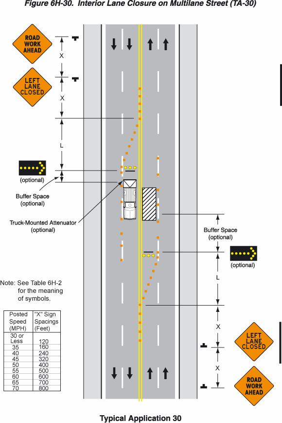
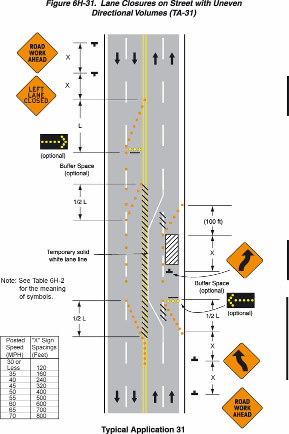
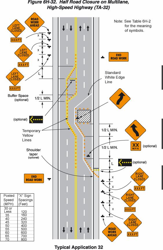
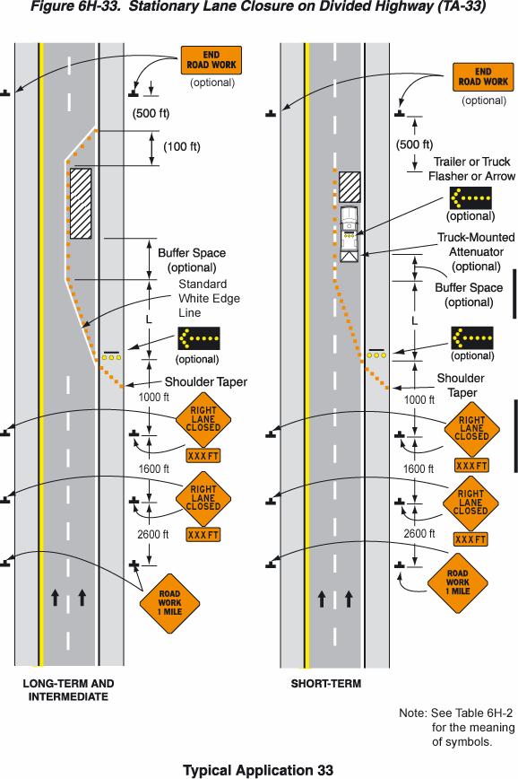
3 Table 6H-1. Index to Typical Applications (Sheet 2 of 2) Typical Application Description Typical Application Number Work Within the Traveled Way of Multilane Undivided Highways (see Section 6G.11) Interior Lane Closure on Multilane Street TA-30 Lane Closure on Street with Uneven Directional Volumes TA-31 Half Road Closure on Multilane, High-Speed Highway TA-32 Work Within the Traveled Way of Multilane Divided Highways (see Section 6G.11) Lane Closure on Divided Highway TA-33 Lane Closure with Temporary Traffic Barrier TA-34 Mobile Operation on Multilane Road TA-35 Work Within the Traveled Way of Expressways and Freeways (see Section 6G.13) Lane Shift on Freeway TA-36 Double Lane Closure on Freeway TA-37 DELETED DELETED Median Crossover on Freeway TA-39 Median Crossover for Entrance Ramp TA-40 Median Crossover for Exit Ramp TA-41 Work in Vicinity of Exit Ramp TA-42 Partial Exit Ramp Closure TA-43 Work in Vicinity of Entrance Ramp TA-44 Temporary Reversible Lane Using Movable Barriers TA-45 A & B Work in the Vicinity of Highway-Rail Grade Crossings (see Section 6G.18) Work in Vicinity of Highway-Rail Grade Crossing TA-46 6H-3
4 6H-4
5 Table 6H-3. Suggested Advance Warning Sign Spacing Road Classification Posted Speed (MPH) Sign Spacing (Feet) Conventional Highways * * * * * 900 Notes: Expressways or Freeways All Speeds *Distance between signs should be increased to have 1500 feet advance warning. **Distance between signs should be increased to have ½ mile or more advance warning. See Typical Applications** Formulas for L are as follows: For speed limits of 40 mph or less: L = WS 2) 60 For speed limits of 45 mph or greater: L = WS Where: L = taper length in feet W = width of offset in feet S = posted speed limit, or off-peak 85th-percentile speed prior to work starting, or the anticipated operating speed in mph 6H-5
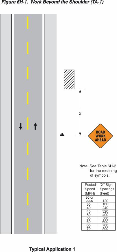
6 Notes for Figure 6H-1 Typical Application 1 Work Beyond the Shoulder 1. If the work space is in the median of a divided highway, an advance warning sign should also be placed on the left side of the directional roadway. Option: 2. The ROAD WORK AHEAD sign may be replaced with other appropriate signs such as the SHOULDER WORK sign. The SHOULDER WORK sign may be used for work adjacent to the shoulder. 3. The ROAD WORK AHEAD sign may be omitted where the work space is behind a barrier, more than 600 mm (24 in) behind the curb, or 4.5 m (15 ft) or more from the edge of any roadway. 4. For short-term, short-duration or mobile operation, all signs and channelizing devices may be eliminated if a vehicle with activated rotating lights or strobe lights is used. Standard: 5. Although vehicle hazard warning signals can be used to supplement the rotating lights or strobe lights, they shall not be used instead of rotating lights or strobe lights. 6H-6
7 6H-7
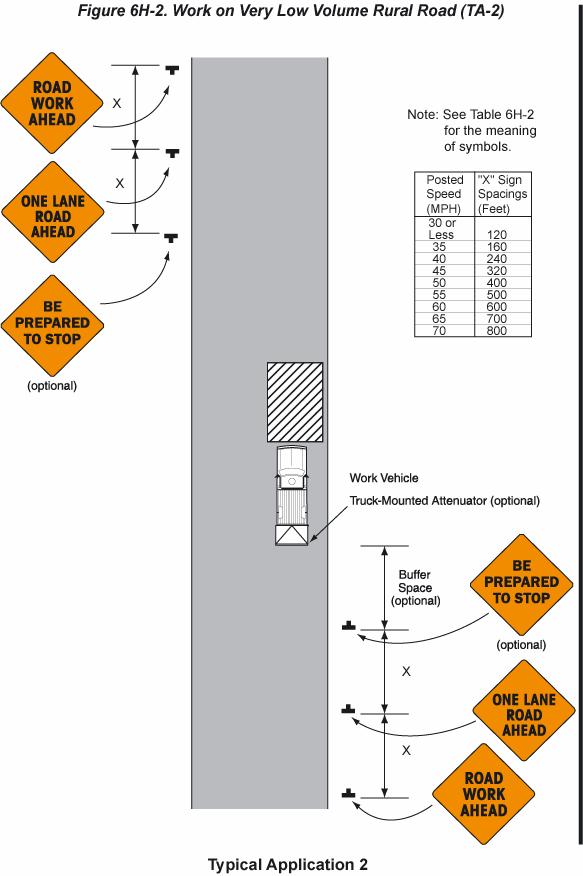
8 Notes for Figure 6H-2 Typical Application 2 Very Low Volume Rural Road Short-Duration Operation 1. The treatment shown should only be used in daytime conditions on very low volume (typically less than 100 ADT) self-regulating rural roads. 2. In situations where a single work vehicle/equipment is being used, adequate sight distance should be maintained. Option: 3. Flaggers or shadow vehicles may be necessary in areas of limited sight distance. Standard: 4. In areas where vehicle traffic cannot effectively self-regulate one or two flaggers shall be used as illustrated in Figure 6H Although vehicle hazard warning signals can be used to supplement the rotating lights or strobe lights, they shall not be used instead of rotating light or strobe lights. 6H-8
9 6H-9
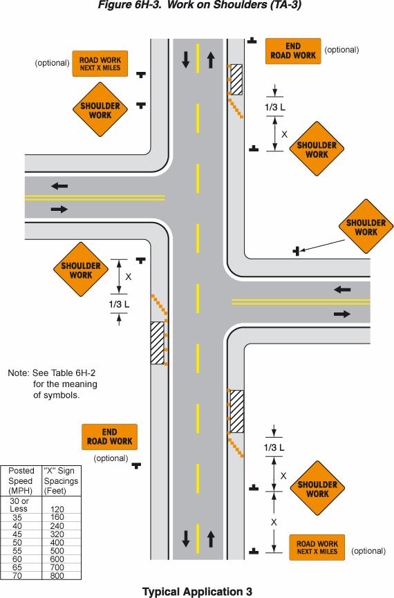
10 Notes for Figure 6H-3 Typical Application 3 Work on Shoulders 1. A SHOULDER WORK sign should be placed on the left side of the roadway for a divided or one-way street only if the left shoulder is affected. Option: 2. The Workers symbol signs may be used instead of SHOULDER WORK signs. 3. The SHOULDER WORK AHEAD sign on an intersecting roadway may be omitted where drivers emerging from that roadway will encounter another advance warning sign prior to this activity area. 4. For short-duration operations of 60 minutes or less, all signs and channelizing devices may be eliminated if a vehicle with activated rotating lights or strobe lights is used. Standard: 5. Although vehicle hazard warning signals can be used to supplement the rotating lights or strobe lights, they shall not be used instead of rotating lights or strobe lights. 6H-10
11 6H-11
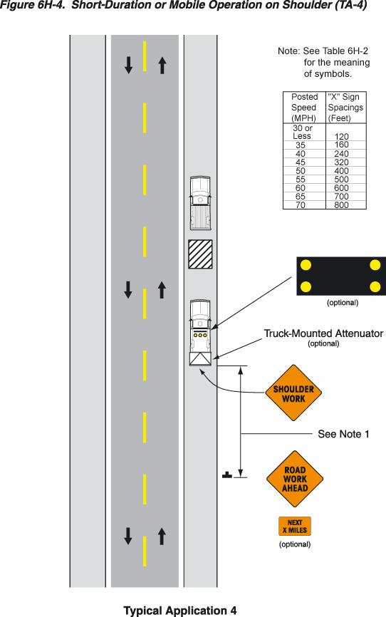
12 Notes for Figure 6H-4 Typical Application 4 Short-Duration or Mobile Operation on Shoulder 1. In those situations where multiple work locations within a limited distance make it practical to place stationary signs, the distance between the advance warning sign and the work should not exceed 3.2 km (2 mile maximum). Option: 2. Warning signs may be omitted when the work vehicle displays rotating lights or strobe lights if the distance between work locations is 1.6 km (1 mile) or more, and if the work vehicle travels at motor vehicle traffic speeds between locations. Standard: 3. Although vehicle hazard warning signals can be used to supplement the rotating lights or strobe lights, they shall not be used instead of rotating lights or strobe lights. 4. If an arrow panel is used for an operation on the shoulder, the caution mode shall be used. 6H-12
13 6H-13
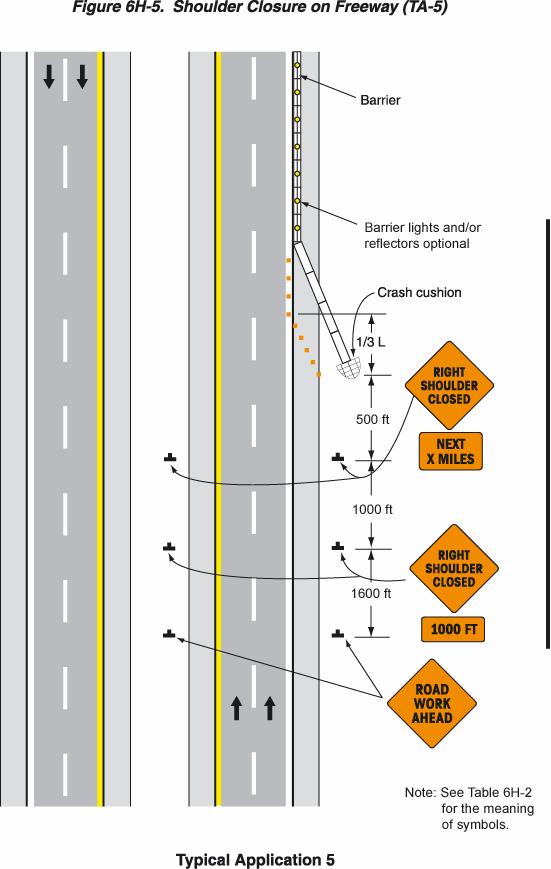
14 Notes for Figure 6H-5 Typical Application 5 Shoulder Closure on Freeway 1. SHOULDER CLOSED signs should be used on limited-access highways where there is no opportunity for disabled vehicles to pull off the roadway. 2. If drivers cannot see a pull-off area beyond the closed shoulder, information regarding the length of the shoulder closure should be provided in meters or kilometers (feet or miles), as appropriate. 3. The use of a temporary traffic barrier should be based on engineering judgment. (see Section 6F.75). Option: 4. The barrier shown in this typical application is an example of one method that may be used to close a shoulder of a long-term project. 5. The warning lights or reflectors shown on the barrier may be used. 6H-14
15 6H-15
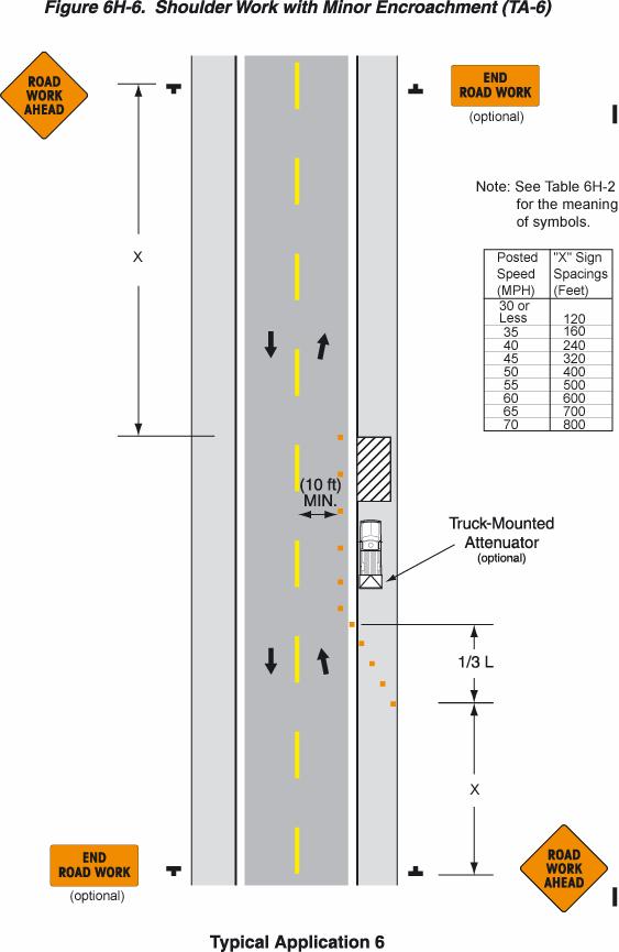
16 Notes for Figure 6H-6 Typical Application 6 Shoulder Work with Minor Encroachment 1. All lanes should be a minimum of 3 m (10 ft) in width as measured to the near face of the channelizing devices. 2. The treatment shown should be used on a minor road having low speeds. For higher-speed traffic conditions, a lane closure should be used. Option: 3. For short-term use on low-volume, low-speed roadways with motor vehicle traffic that does not include longer and wider heavy commercial vehicles, a minimum lane width of 2.7 m (9 ft) may be used. 4. Where the opposite shoulder is suitable for carrying motor vehicle traffic and of adequate width, lanes may be shifted by use of closely spaced channelizing devices, provided that the minimum lane width of 3 m (10 ft) is maintained. 5. Additional advance warning may be appropriate, such as a ROAD NARROWS sign. 6. Temporary traffic barriers may be used along the work space. 7. The shadow vehicle may be omitted if a taper and channelizing devices are used. 8. A truck-mounted attenuator may be used on the shadow vehicle. 9. For short-duration work, the taper and channelizing devices may be omitted if a shadow vehicle with activated rotating lights or strobe lights is used. Standard: 10. Although vehicle hazard warning signals can be used to supplement the rotating lights or strobe lights, they shall not be used instead of rotating lights or strobe lights. 6H-16
17 6H-17
18 Notes for Figure 6H-7 Typical Application 7 Road Closure with Diversion Standard: 1. Signs and object markers are shown for one direction of travel only. Devices similar to those depicted shall be placed for the opposite direction of travel. 2. Pavement markings no longer applicable shall be removed or obliterated as soon as practicable. 3. Roadside barriers and end treatment shall be crashworthy. 4. If the tangent distance along the temporary diversion is short and the curvature is sharp, the Winding Road sign should be used at the location of the first Reverse Curve sign. The second Reverse Curve sign should be omitted. 5. Where the temporary pavement and old pavement are different colors, the temporary pavement should start on the tangent of the existing pavement and end on the tangent of the existing pavement. 6. If the diversion has sharp curves with recommended speeds of 50 km/h (30 mph) or less, Reverse Turn signs should be used. Option: 7. Flashing warning lights and/or flags may be used to call attention to the warning signs. 8. Delineators or channelizing devices may be used along the diversion. 6H-18

19 6H-19
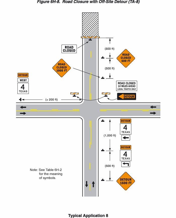
20 Notes for Figure 6H-8 Typical Application 8 Road Closure with Off-Site Detour 1. Regulatory traffic control devices should be modified as needed for the duration of the detour. 2. If the road is opened for some distance beyond the intersection and/or there are significant origin/destination points beyond the intersection, the ROAD CLOSED and DETOUR signs with Type III Barricades should be located at the edge of the traveled way. Option: 3. If the road is closed a short distance beyond the intersection and there are few origin/ destination points beyond (for example, a few residences), the ROAD CLOSED and DETOUR sign may be placed with a Type III Barricade placed in the center of the roadway. 4. A Route Marker Directional assembly may be placed on the far left corner of the intersection to augment or replace the one shown on the near right corner. 5. Flashing warning lights and/or flags may be used to call attention to the advance warning signs. 6H-20
21 6H-21
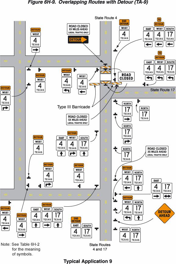
22 Notes for Figure 6H-9 Typical Application 9 Overlapping Routes with Detour Support: 1. Temporary traffic control devices are shown for one direction of travel only. Standard: 2. Devices similar to those depicted shall be placed for the opposite direction of travel. 3. STOP signs displayed to side roads should be installed as needed along the temporary route. 4. Cardinal direction plaques should be used with route markers. Option: 5. Flashing warning lights and/or flags may be used to call attention to the advance warning signs. 6H-22
23 6H-23
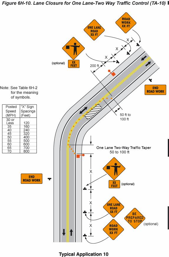
24 Notes for Figure 6H-10 Typical Application 10 Lane Closure for One Lane-Two Way Traffic Control Option: 1. For low-volume situations with short work zones on straight roadways where the flagger is visible to road users approaching from both directions, a single flagger, positioned to be visible to road users approaching from both directions, may be used (see Chapter 6E). 2. The ROAD WORK AHEAD and the END ROAD WORK signs may be omitted for shortduration operations. 3. Flashing warning lights and/or flags may be used to call attention to the advance warning signs. A BE PREPARED TO STOP sign may be added to the sign series. 4. A flagger or a law enforcement officer may be used at the highway-rail grade crossing to minimize the probability that vehicles are stopped within 4.5 m (15 ft) of the highway-rail grade crossing, measured from both sides of the outside rails. 5. Channelizing devices should be extended to a point where they are visible to approaching road users. 6. Floodlights should be provided as needed to mark flagger stations at night. 7. When used, the BE PREPARED TO STOP sign should be located between the Advance Flagger sign and the ONE LANE ROAD sign. 8. When a highway-rail grade crossing exists within or upstream of the transition area and it is anticipated that backups resulting from the lane closure might extend through the highway-rail grade crossing, the temporary traffic control zone should be extended so that the transition area precedes the highway-rail grade crossing. 9. When a highway-rail grade crossing equipped with active warning devices exists within the activity area, provisions should be made for keeping flaggers informed as to the activation status of these warning devices. 10. When a highway-rail grade crossing exists within the activity area, drivers operating on the left side of the normal centerline should be provided with comparable warning devices as for drivers operating on the right side of the normal centerline. 11. Early coordination with the railroad company should occur before work starts. 12. Access should be controlled throughout the construction or maintenance work zone. Closure of all entering intersections within the zone should be considered. Driveways create a problem that should be monitored by flaggers. Flaggers should have good visual contact or two-way radio contact with each other. 13. Length of work area should be based on the ability of flaggers to communicate. 6H-24
25 6H-25
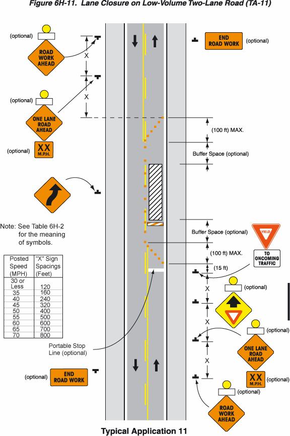
26 Notes for Figure 6H-11 Typical Application 11 Lane Closure on Low-Volume Two-Lane Road Option: 1. This temporary traffic control zone application may be used as an alternate temporary traffic control plan to the lane closure with flaggers (Figure 6H-10), when the following conditions exist: a. Motor vehicle traffic volume is such that sufficient gaps exist for motor vehicle traffic that must yield. b. Drivers from both directions are able to see approaching motor vehicle traffic through and beyond the work site. Standard: 2. When flaggers are used, the Flagger symbol sign shall be used in place of the YIELD AHEAD sign. Option: 3. The Type A flashing warning lights may be placed on the ROAD WORK AHEAD, ONE LANE ROAD AHEAD and the YIELD AHEAD signs whenever a night lane closure is necessary. 6H-26
27 6H-27
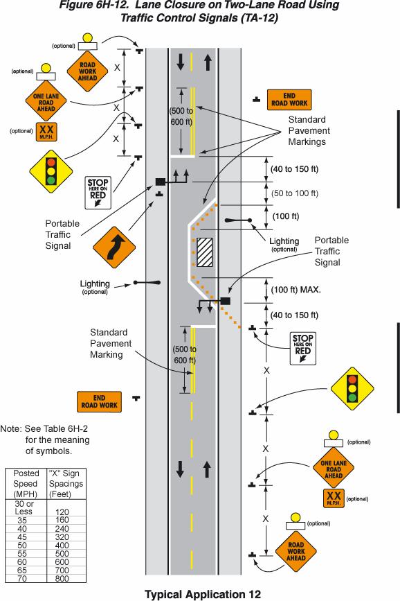
28 Notes for Figure 6H-12 Typical Application 12 Lane Closure on Two-Lane Road Using Traffic Control Signals Standard: 1. Temporary traffic control signals shall be installed and operated in accordance with the provisions of Part 4. Temporary traffic control signals shall meet the physical display and operational requirements of conventional traffic control signals. 2. Temporary traffic control signal timing shall be established by qualified officials. 3. When the temporary traffic control signal is changed to the flashing mode, either manually or automatically, red signal indications shall be flashed to both approaches. 4. Stop lines shall be installed with temporary traffic control signals. Existing conflicting pavement markings and raised pavement marker reflectors between the activity area and the stop line shall be removed. After the temporary traffic control signal is removed, the stop lines and other temporary pavement markings shall be removed and the permanent pavement markings restored. 5. Where no-passing lines are not already in place, they should be added. 6. Adjustments in the location of the advance warning signs should be made as needed to accommodate the horizontal or vertical alignment of the roadway, recognizing that the distances shown for sign spacings are minimums. Adjustments in the height of the signal heads should be made as needed to conform to the vertical alignment. Option: 7. Flashing warning lights shown on the ROAD WORK AHEAD and the ONE LANE ROAD AHEAD signs may be used. 8. Removable pavement markings may be used. Support: 9. Temporary traffic control signals are preferable to flaggers for long-term projects and other activities that would require flagging at night. 10. The maximum length of activity area for one-way operation under temporary traffic control signal control is determined by the capacity required to handle the peak demand. 6H-28
29 6H-29
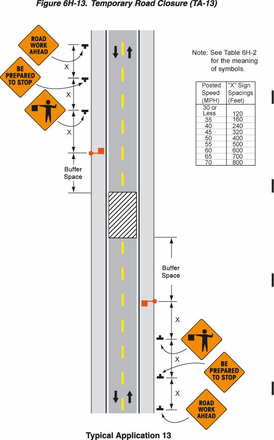
30 Notes for Figure 6H-13 Typical Application 13 Temporary Road Closure Support: 1. Conditions represented are a planned closure not exceeding 20 minutes during the daytime. Standard: 2. The flagger shall follow the procedures noted in Sections 6E.04 and 6E A BE PREPARED TO STOP sign shall be located before the Flagger symbol sign. Option: 4. A law enforcement officer and/or a changeable message sign may be used. 6H-30
31 6H-31
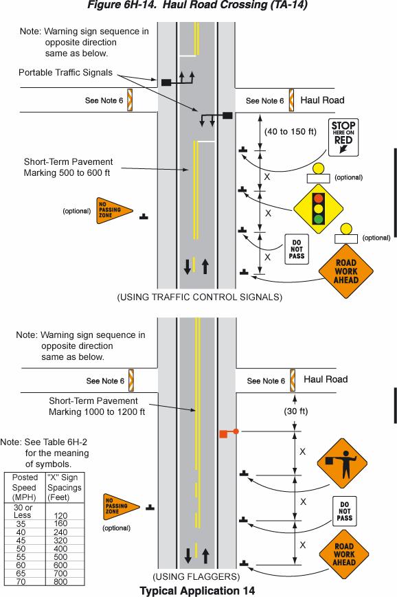
32 Notes for Figure 6H-14 Typical Application 14 Haul Road Crossing 1. Floodlights should be used to illuminate haul road crossings where existing light is inadequate. 2. Where no passing lines are not already in place, they should be added. Standard: 3. The traffic control method selected shall be used in both directions. Flagging Method 4. When a road used exclusively as a haul road is not in use, Type III barricades shall be in place and the Flagger symbol signs covered or removed. 5. The flagger shall follow the procedures noted in Sections 6E.04 and 6E.05. Signalized Method 6. When a road used exclusively as a haul road is not in use, Type III barricades shall be in place. The signals shall either flash yellow on the main road or be covered, and the Signal Ahead and STOP HERE ON RED signs shall be covered or hidden from view. 7. The temporary traffic control signals shall control both the highway and the haul road and shall meet the physical display and operational requirements of conventional traffic control signals as described in Part 4. Traffic control signal timing shall be established by authorized officials. 8. Stop lines shall be used on existing highway with temporary traffic control signals. 9. Existing conflicting pavements markings between the stop lines shall be removed. After the temporary traffic control signal is removed, the stop lines and other temporary pavement markings shall be removed and the permanent pavement markings restored. 6H-32
33 6H-33
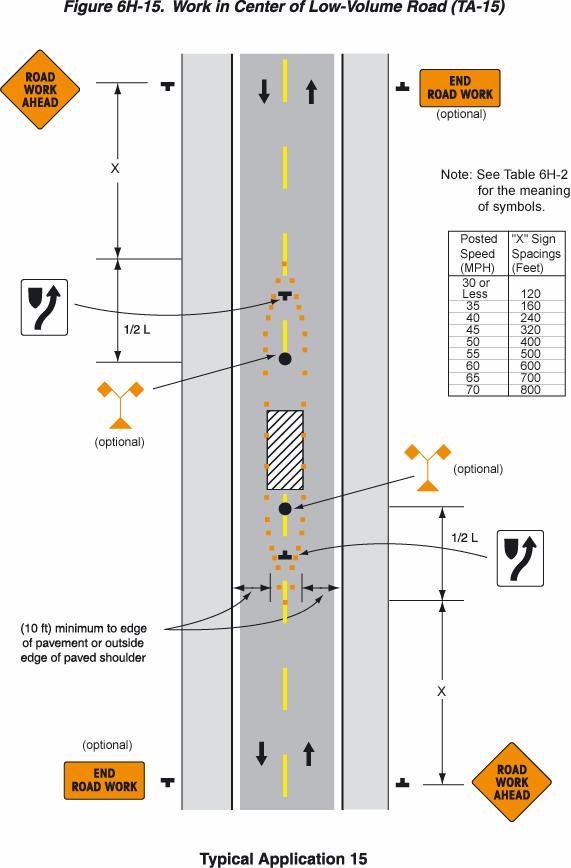
34 Notes for Figure 6H-15 Typical Application 15 Work in Center of Low-Volume Road 1. The lanes on either side of the center work space should have a minimum width of 3 m (10 ft) as measured from the near edge of the channelizing devices to the edge of pavement or the outside edge of paved shoulder. Option: 2. Flashing warning lights and/or flags may be used to call attention to the advance warning signs. 3. If the closure continues overnight, warning lights may be used on the channelizing devices. 4. A lane width of 2.7 m (9 ft) may be used for short-term stationary work on low-volume, low-speed roadways when motor vehicle traffic does not include longer and wider heavy commercial vehicles. 5. A work vehicle displaying rotating lights or strobe lights may be used instead of the channelizing devices forming the tapers or the high-level warning devices. Standard: 6. Although vehicle hazard warning signals can be used to supplement the rotating lights or strobe lights, they shall not be used instead of rotating lights or strobe lights. 6H-34
35 6H-35
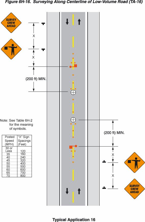
36 Notes for Figure 6H-16 Typical Application 16 Surveying Along Centerline of Low-Volume Road 1. Cones should be placed 150 mm (6 in) to 300 mm (12 in) on either side of the centerline. 2. Spacing of channelizing devices should not exceed a distance in feet equal to the speed limit (mph) when used for the taper channelization and a distance in feet of 2 times the speed limit (mph) when used for tangent channelization. 3. A flagger should be used to warn workers who cannot watch road users. 4. Workers in the roadway should wear high-visibility clothing. Standard: 5. For surveying on the centerline of a high-volume road, one lane shall be closed using the information illustrated in Figure 6H-10. Option: 6. A high-level warning device may be used to protect a surveying device, such as a target on a tripod. 7. Cones may be omitted for a cross-section survey. 8. ROAD WORK AHEAD signs may be used in place of the SURVEY CREW AHEAD signs. 9. Flags may be used to call attention to the advance warning signs. 10. If the work is along the shoulder, the flagger may be omitted. 11. For a survey along the edge of the road or along the shoulder, cones may be placed along the edge line. 12. A BE PREPARED TO STOP sign may be added to the sign series. 13. When used, the BE PREPARED TO STOP sign should be located before the Flagger symbol sign. 6H-36
37 6H-37
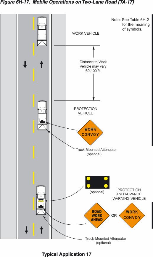
38 Notes for Figure 6H-17 Typical Application 17 Mobile Operations on Two-Lane Road Standard: 1. Vehicle-mounted signs shall be mounted with the bottom of the sign at a minimum height of 1,200 mm (48 in) above the pavement. Sign legends shall be covered or turned from view when work is not in progress. 2. Shadow and work vehicles shall display rotating lights or strobe lights. 3. The shadow vehicles shall also be equipped with two high-intensity flashing lights mounted on the rear, adjacent to the sign. 4. Where practical and when needed, the work and shadow vehicles should pull over periodically to allow motor vehicle traffic to pass. 5. Whenever adequate stopping sight distance exists to the rear, the shadow vehicle should maintain the minimum distance from the work vehicle and proceed at the same speed. The shadow vehicle should slow down in advance of vertical or horizontal curves that restrict sight distance. 6. A truck-mounted attenuator should be used on the shadow vehicle. Option: 7. The distance between the work and shadow vehicles may vary according to terrain, work activity and other factors. 8. Additional shadow vehicles to warn and reduce the speed of oncoming or opposing motor vehicle traffic may be used. Police patrol cars may be used for this purpose. 9. A truck-mounted attenuator may be used on the work vehicle. 10. If the work and shadow vehicles cannot pull over to allow motor vehicle traffic to pass frequently, a DO NOT PASS sign may be placed on the rear of the vehicle blocking the lane. Support: 11. Shadow vehicles are used to warn motor vehicle traffic of the operation ahead. 6H-38
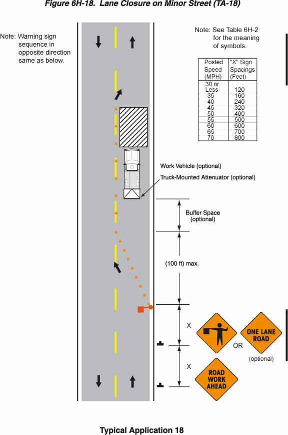
39 6H-39
40 Notes for Figure 6H-18 Typical Application 18 Lane Closure on Minor Street Standard: 1. This temporary traffic control shall be used only for low-volume, low-speed facilities. Option: 2. Where the work space is short, where drivers can see the roadway beyond, and where volume is low, motor vehicle traffic may be self-regulating. Standard: 3. Where motor vehicle traffic cannot effectively self-regulate, one or two flaggers shall be used as illustrated in Figure 6H-10. Option: 4. Flashing warning lights and/or flags may be used to call attention to the advance warning signs. 5. A truck-mounted attenuator may be used on the work vehicle and the shadow vehicle. 6H-40
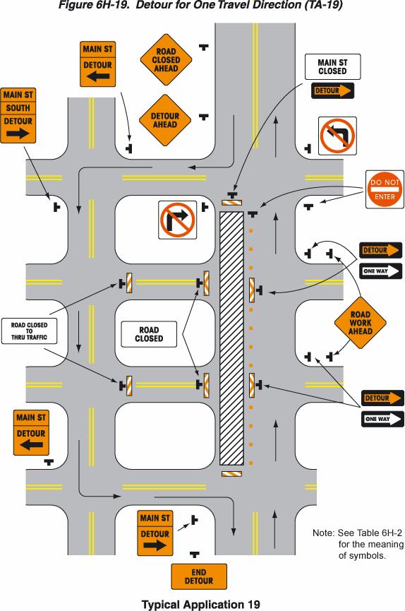
41 6H-41
42 Notes for Figure 6H-19 Typical Application 19 Detour for One Travel Direction Option: 1. The STREET CLOSED legend may be used in place of ROAD CLOSED. 2. Additional DO NOT ENTER signs may be used at intersections with intervening streets. 3. Warning lights may be used on Type III Barricades. 4. Detour signs may be located on the far side of intersections. 5. A Street Name sign may be mounted with the Detour sign. The Street Name sign may be either white on green or black on orange. Standard: 6. When used, the Street Name sign shall be placed above the Detour sign. 6H-42
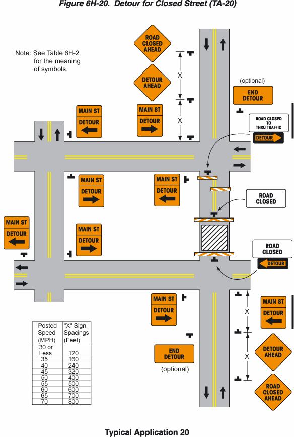
43 6H-43
44 Notes for Figure 6H-20 Typical Application 20 Detour for Closed Street 1. This plan should be used for streets without posted highway system route numbers. 2. On multilane streets, Detour signs with an Advance Turn Arrow should be used in advance of a turn. Option: 3. Flashing warning lights and/or flags may be used to call attention to the advance warning signs. 4. Flashing warning lights may be used on Type III Barricades. 5. Detour signs may be located on the far side of intersections. A Detour sign with an advance arrow may be used in advance of a turn. 6. A Street Name sign may be mounted with the Detour sign. The Street Name sign may be either white on green or black on orange. Standard: 7. When used, the Street Name sign shall be placed above the Detour sign. Support: 8. See Figure 6H-9 for the information for detouring a numbered highway. 6H-44
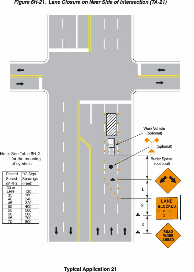
45 6H-45
46 Notes for Figure 6H-21 Typical Application 21 Lane Closure on Near Side of Intersection Standard: 1. The merging taper shall direct motor vehicle traffic into either the right or left lane, but not both. 2. In this typical application, a left taper should be used so that right-turn movements will not impede through motor vehicle traffic. However, the reverse should be true for left-turn movements. 3. If the work space extends across the crosswalk, the crosswalk should be closed using the information and devices shown in Figure 6H-29. Option: 4. Flashing warning lights and/or flags may be used to call attention to the advance warning signs. 5. A shadow vehicle with a truck-mounted attenuator may be used. 6. A work vehicle with rotating lights or strobe lights may be used with the high-level warning device. Standard: 7. Although vehicle hazard warning signals can be used to supplement the rotating lights or strobe lights, they shall not be used instead of rotating lights or strobe lights. 6H-46
47 6H-47
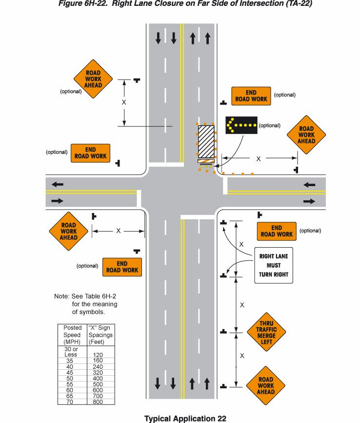
48 Notes for Figure 6H-22 Typical Application 22 Right Lane Closure on Far Side of Intersection 1. If the work space extends across the crosswalk, the crosswalk should be closed using the information and devices shown in Figure 6H-29. Option: 2. The normal procedure is to close on the near side of the intersection any lane that is not carried through the intersection. However, when this results in the closure of a right lane having significant right turning movements, then the right lane may be restricted to right turns only, as shown. This procedure increases the through capacity by eliminating right turns from the open through lane. 3. For intersection approaches reduced to a single lane, left-turning movements may be prohibited to maintain capacity for through motor vehicle traffic. 4. Flashing warning lights and/or flags may be used to call attention to the advance warning signs. 5. Where the turning radius is large, it may be possible to create a right-turn island using channelizing devices (see Figure 6H-24). 6H-48
49 6H-49
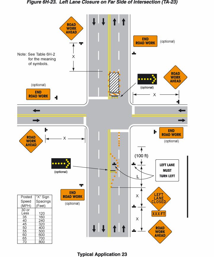
50 Notes for Figure 6H-23 Typical Application 23 Left Lane Closure on Far Side of Intersection 1. If the work space extends across the crosswalk, the crosswalk should be closed using the information and devices shown in Figure 6H-29. Option: 2. Flashing warning lights and/or flags may be used to call attention to the advance warning signs. 3. The normal procedure is to close on the near side of the intersection any lane that is not carried through the intersection. However, when this results in the closure of a left lane having significant left-turning movements, then the left lane may be converted to a turn bay for left turns only, as shown. Support: 4. By first closing off the left lane and then reopening it as a turn bay, an island is created with channelizing devices that allows the LEFT LANE MUST TURN LEFT sign to be repeated on the left adjacent to the lane that it controls. 6H-50
51 6H-51
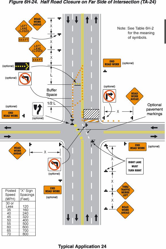
52 Notes for Figure 6H-24 Typical Application 24 Half Road Closure on Far Side of Intersection 1. If the work space extends across the crosswalk, the crosswalk should be closed using the information and devices shown in Figure 6H When turn prohibitions are implemented, two turn prohibition signs should be used, one on the near side and, space permitting, one on the far side of the intersection. Option: 3. A buffer space may be used between opposing directions of motor vehicle traffic as shown in this application. 4. The normal procedure is to close on the near side of the intersection any lane that is not carried through the intersection. However, if there is a significant right-turning movement, then the right lane may be restricted to right turns only, as shown. 5. Where the turning radius is large, a right-turn island using channelizing devices or pavement markings may be used, as shown. 6. There may be insufficient space to place the back-to-back Keep Right sign and No Left Turn symbol signs at the end of the row of channelizing devices separating opposing motor vehicle traffic flows. In this situation, the No Left Turn symbol sign may be placed on the right and the Keep Right sign may be omitted. 7. For intersection approaches reduced to a single lane, left-turning movements may be prohibited to maintain capacity for through motor vehicle traffic. 8. Flashing warning lights and/or flags may be used to call attention to advance warning signs. 9. Temporary pavement markings may be used to delineate the travel path through the intersection. Support: 10. Keeping the right lane open increases the through capacity by eliminating right turns from the open through lane. 11. A temporary turn island reinforces the nature of the temporary exclusive right-turn lane and enables a second RIGHT LANE MUST TURN RIGHT sign to be placed in the island. 6H-52
53 6H-53
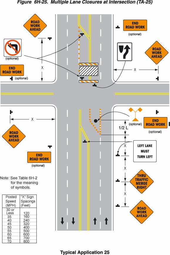
54 Notes for Figure 6H-25 Typical Application 25 Multiple Lane Closures at Intersection 1. If the work space extends across the crosswalk, the crosswalk should be closed using the information and devices shown in Figure 6H If the left through lane is closed on the near-side approach, the LEFT LANE MUST TURN LEFT sign should be placed in the median to discourage through motor vehicle traffic from entering the left-turn bay. Option: 3. The normal procedure is to close on the near side of the intersection any lane that is not carried through the intersection. If the left-turning movement that normally uses the closed turn bay is small and/or the gaps in opposing motor vehicle traffic are frequent, left turns may be permitted on that approach. 4. Flashing warning lights and/or flags may be used to call attention to the advance warning signs. 6H-54
55 6H-55
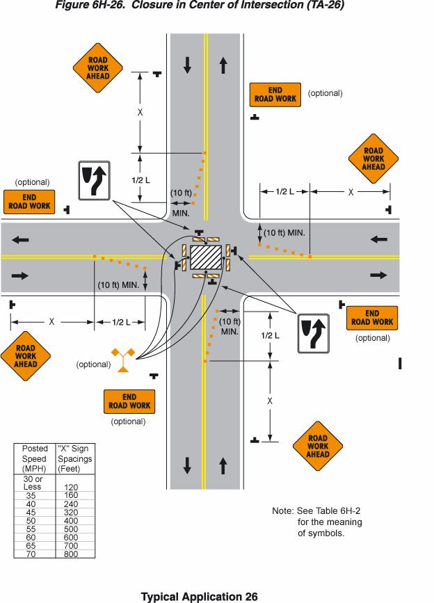
56 Notes for Figure 6H-26 Typical Application 26 Closure in Center of Intersection 1. A high-level warning device should be placed in the work space, if there is sufficient room. 2. All lanes should be a minimum of 3 m (10 ft) in width as measured to the near face of the channelizing devices. Option: 3. For short-term use on low-volume, low-speed roadways with motor vehicle traffic that does not include longer and wider heavy commercial vehicles, a minimum lane width of 2.7 m (9 ft) may be used. 4. Flashing warning lights and/or flags may be used to call attention to advance warning signs. 5. Unless the streets are wide, it may be physically impossible to turn left, especially for large vehicles. Left turns may be prohibited as required by geometric conditions. 6. For short-duration work operations, the channelizing devices may be eliminated if a vehicle displaying rotating lights or strobe lights is positioned in the work space. Standard: 7. Although vehicle hazard warning signals can be used to supplement the rotating lights or strobe lights, they shall not be used instead of rotating lights or strobe lights. 6H-56
57 6H-57
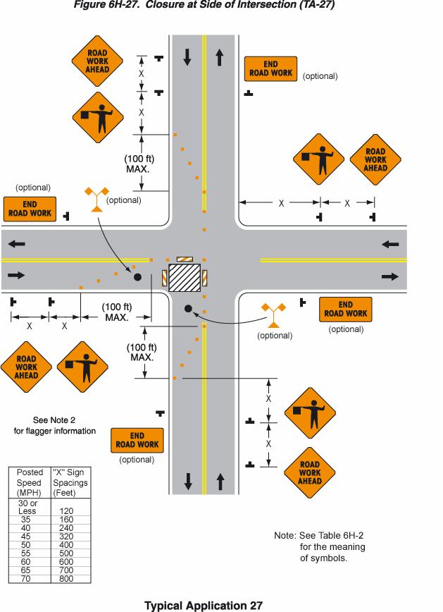
58 Notes for Figure 6H-27 Typical Application 27 Closure at Side of Intersection 1. The situation depicted can be simplified by closing one or more of the intersection approaches. If this cannot be done, and/or when capacity is a problem, through motor vehicle traffic should be directed to other roads or streets. 2. Depending on road user conditions, flagger(s) or uniformed law enforcement officer(s) should be used to direct road users within the intersection. Option: 3. ONE LANE ROAD AHEAD signs may also be used to provide adequate advance warning. 4. Flashing warning lights and/or flags may be used to call attention to the advance warning signs. 5. For short-duration work operations, the channelizing devices may be eliminated if a vehicle displaying rotating lights or strobe lights is positioned in the work space. 6. A BE PREPARED TO STOP sign may be added to the sign series. 7. When used, the BE PREPARED TO STOP sign should be located before the Flagger symbol sign. Support: 8. Turns can be prohibited as required by motor vehicle traffic conditions. Unless the streets are wide, it may be physically impossible to make certain turns, especially for large vehicles. Standard: 9. Although vehicle hazard warning signals can be used to supplement the rotating lights or strobe lights, they shall not be used instead of rotating lights or strobe lights. 6H-58
59 6H-59
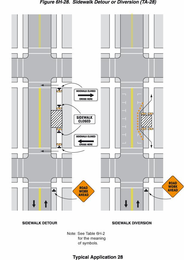
60 Notes for Figure 6H-28 Typical Application 28 Sidewalk Closures and Bypass Sidewalks Standard: 1. Where sidewalks exist, provisions shall be made for disabled pedestrians. 2. Where high speeds are anticipated, a temporary traffic barrier should be used to separate the temporary sidewalks from motor vehicle traffic. Option: 3. Street lighting may be considered. 4. Only the temporary traffic control devices related to pedestrians are shown. Other devices, such as lane closure signing or ROAD NARROWS signs, may be used to control motor vehicle traffic. 5. For nighttime closures, Type A Flashing warning lights may be used on barricades that support signs and close sidewalks. 6. Type C Steady-Burn warning lights may be used on channelizing devices separating the temporary sidewalks from motor vehicle traffic flow. 7. Signs, such as KEEP RIGHT (LEFT), may be placed along a temporary sidewalk to guide or direct pedestrians. 6H-60
61 6H-61
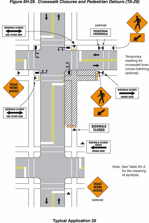
62 Notes for Figure 6H-29 Typical Application 29 Crosswalk Closures and Pedestrian Detours Standard: 1. Where sidewalks exist, provisions shall be made for disabled persons. 2. Curb parking shall be prohibited for at least 15 m (50 ft) in advance of the midblock crosswalk. 3. Pedestrian traffic signal displays controlling closed crosswalks should be covered or deactivated. Option: 4. Street lighting may be considered. 5. Only the temporary traffic control devices related to pedestrians are shown. Other devices, such as lane closure signing or ROAD NARROWS signs, may be used to control motor vehicle traffic. 6. For nighttime closures, Type A Flashing warning lights may be used on barricades supporting signs and closing sidewalks. 7. Type C Steady-Burn warning lights may be used on channelizing devices separating the work space from motor vehicle traffic. 8. In order to maintain the systematic use of the fluorescent yellow-green background for pedestrian, bicycle, and school warning signs in a jurisdiction, the fluorescent yellow-green background for pedestrian, bicycle, and school warning signs may be used in temporary traffic control zones. 6H-62
63 6H-63
64 Notes for Figure 6H-30 Typical Application 30 Interior Lane Closure on Multilane Street 1. This information applies to low-speed, low-volume urban streets. Where speed or volume is higher, additional signing such as LEFT LANE CLOSED XX M (FT) should be used between the signs shown. Option: 2. The closure of the adjacent interior lane in the opposing direction may not be necessary, depending upon the activity being performed and the work space needed for the operation. 3. Shadow vehicles with a truck-mounted attenuator may be used. 4. When a highway-rail grade crossing exists within or upstream of the transition area and it is anticipated that backups resulting from the lane closure might extend through the highway-rail grade crossing, the temporary traffic control zone should be extended so that the transition area precedes the highway-rail grade crossing. 5. Early coordination with the railroad company should occur before work starts. 6H-64
65 6H-65
66 Notes for Figure 6H-31 Typical Application 31 Lane Closure on Street with Uneven Directional Volumes Standard: 1. The illustrated information shall be used only when the motor vehicle traffic volume indicates that two lanes of motor vehicle traffic shall be maintained in the direction of travel for which one lane is closed. Option: 2. The procedure may be used during a peak period of motor vehicle traffic and then changed to provide two lanes in the other direction for the other peak. 3. For high speeds, a RIGHT/LEFT LANE CLOSED XX M (FT) sign should be added for motor vehicle traffic approaching the lane closure, as shown in Figure 6H Conflicting pavement markings should be removed for long-term projects. For short-term and intermediate-term projects where this is not practical, the channelizing devices in the area where the pavement markings conflict should be placed at a maximum spacing of 0.1 S km (0.5 S feet) where S is the speed. Temporary markings should be installed where needed. 5. If the lane shift has curves with recommended speeds of 50 km/h (30 mph) or less, Reverse Turn signs should be used. 6. Where the shifted section is long, a Reverse Curve sign should be used to show the initial shift and a second sign should be used to show the return to the normal alignment. 7. If the tangent distance along the temporary diversion is less than 180 m (600 ft), the Winding Road sign should be used at the location of the first Reverse Curve sign. The second Reverse Curve sign should be omitted. Option: 8. A longitudinal buffer space may be used in the activity area to separate opposing motor vehicle traffic. 9. As an alternative, a Double Lane Shift sign may be used displaying one arrow for each lane. An ALL LANES THRU supplemental plaque may be used to emphasize the point that all lanes shift and no lanes are closed. 10. A work vehicle or a shadow vehicle may be equipped with a truck-mounted attenuator. 6H-66
67 6H-67
68 Notes for Figure 6H-32 Typical Application 32 Half Road Closure on Multilane High-Speed Highway Standard: 1. Pavement markings no longer applicable shall be removed or obliterated as soon as practical. Except for intermediate-term and short-term situations, temporary markings shall be provided to clearly delineate the temporary travel path. For short-term and intermediate-term situations where it is not feasible to remove and restore pavement markings, channelization shall be made dominant by using a very close device spacing. 2. Where channelizing devices are used instead of pavement markings, the maximum spacing should be 0.1 S meters, where S is the speed in km/h (0.5 S feet where S is the speed in mph). Option: 3. Warning lights may be used to supplement channelizing devices at night. 4. When a highway-rail grade crossing exists within or upstream of the transition area and it is anticipated that backups resulting from the lane closure might extend through the highway-rail grade crossing, the temporary traffic control zone should be extended so that the transition area precedes the highway-rail grade crossing. 5. When a highway-rail grade crossing exists within the activity area, provisions should be made to provide drivers operating on the left side of the normal centerline with comparable warning devices as supplied for drivers operating on the right side of the normal centerline. 6. Early coordination with the railroad company should occur before work starts. Option: 7. A flagger may be used at the highway-rail grade crossing to minimize the probability that vehicles are stopped within 4.5 m (15 ft) of the highway-rail grade crossing, measured from both sides of the outside rails. 8. A truck-mounted attenuator may be used on the work vehicle and/or the shadow vehicle. 6H-68
69 6H-69
70 Notes for Figure 6H-33 Typical Application 33 Stationary Lane Closure on Divided Highway Standard: 1. This information also shall be used when work is being performed in the lane adjacent to the median on a divided highway. In this case, the LEFT LANE CLOSED signs and the corresponding LANE REDUCTION signs shall be substituted. 2. When a side road intersects the highway within the temporary traffic control zone, additional temporary traffic control devices shall be placed as needed. 3. All vehicles, equipment, workers and their activities should be restricted to one side of the pavement. Option: 4. A truck-mounted attenuator may be used on the work vehicle and/or shadow vehicle. 6H-70
71 6H-71
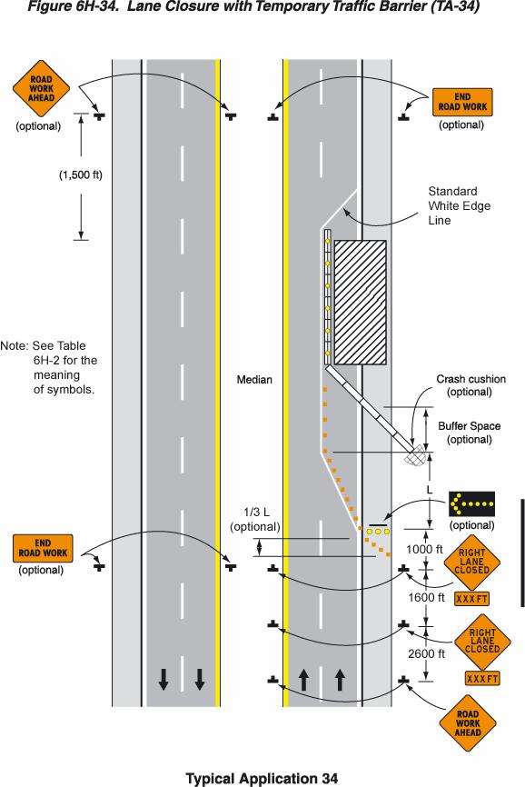
72 Notes for Figure 6H-34 Typical Application 34 Lane Closure with Temporary Traffic Barrier 1. For long-term lane closures on facilities with permanent edge lines, a temporary edge line should be installed from the start of the taper to the downstream point where the barrier crosses the permanent edge line, and conflicting pavement markings should be removed. 2. The use of a barrier should be based on engineering judgment. For end treatments of temporary traffic barriers, see Section 6F.75. Standard: 3. The barrier shall not be placed along the merging taper. The lane shall first be closed using channelizing devices and pavement markings. Option: 4. The barrier shown in this typical application is an example of one method that may be used to close a lane for a long-term project. If the work activity permits, a movable barrier may be used and relocated to the shoulder during nonwork periods or peak-period motor vehicle traffic conditions, as appropriate. 5. Type C Steady-Burn warning lights may be placed on channelizing devices and the barrier parallel to the edge of pavement for nighttime lane closures. Standard: 6. If a movable barrier is used, the temporary white edge line shown in the typical application shall not be used. During the period when the right lane is opened, the sign legends and the channelization shall be changed to indicate that only the shoulder is closed, as illustrated in Figure 6H-5. The arrow panel, if used, shall be placed at the end of the shoulder taper and shall display the caution mode. 7. If a movable barrier is used, the shift should be performed in the following manner. When closing the lane, the lane should be initially closed with channelizing devices placed along a merging taper using the same information employed for a stationary lane closure. The lane closure should then be extended with the movable-barrier transfer vehicle moving with motor vehicle traffic. When opening the lane, the movable-barrier transfer vehicle should travel against motor vehicle traffic from the termination area to the transition area. The merging taper should then be removed using the same information employed for a stationary lane closure. 6H-72
73 6H-73
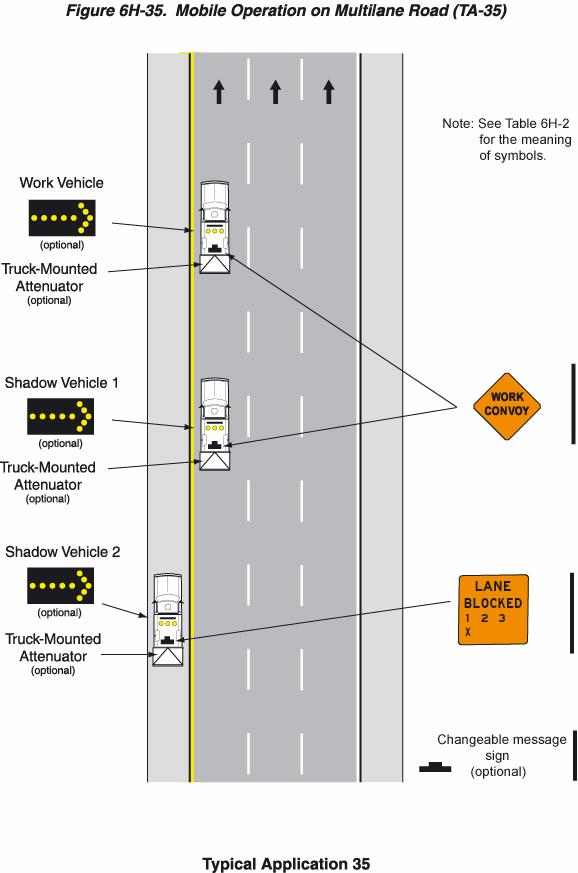
74 Notes for Figure 6H-35 Typical Application 35 Mobile Operation on Multilane Road Standard: 1. Arrow panels shall, as a minimum, be Type B, with a size of 1,500 x 750 mm (60 x 30 in). 2. Vehicles used for these operations should be made highly visible with appropriate equipment, such as: rotating lights, strobe lights, flags, signs, or arrow panels. 3. Shadow Vehicle 1 should be equipped with an arrow panel and truck-mounted attenuator. 4. Shadow Vehicle 2 should be equipped with an arrow panel. An appropriate lane closure sign should be placed on Shadow Vehicle 2 so as not to obscure the arrow panel. 5. Shadow Vehicle 2 should travel at a varying distance from the work operation so as to provide adequate sight distance for motor vehicle traffic approaching from the rear. 6. The spacing between the work vehicles and the shadow vehicles, and between each shadow vehicle should be minimized to deter road users from driving in between. 7. Work should normally be accomplished during off-peak hours. 8. When the work vehicle occupies an interior lane (a lane other than the far right or far left) of a directional roadway having a right shoulder 3 m (10 ft) or more in width, Shadow Vehicle 2 should drive the right shoulder with a sign indicating that work is taking place in the interior lane. Option: 9. A truck-mounted attenuator may be used on Shadow Vehicle On high-speed roadways, a third shadow vehicle (not shown) may be used with Shadow Vehicle 1 in the closed lane, Shadow Vehicle 2 straddling the edge line, and Shadow Vehicle 3 on the shoulder. 11. Where adequate shoulder width is not available, Shadow Vehicle 3 may drive partially in the lane. 6H-74
75 6H-75
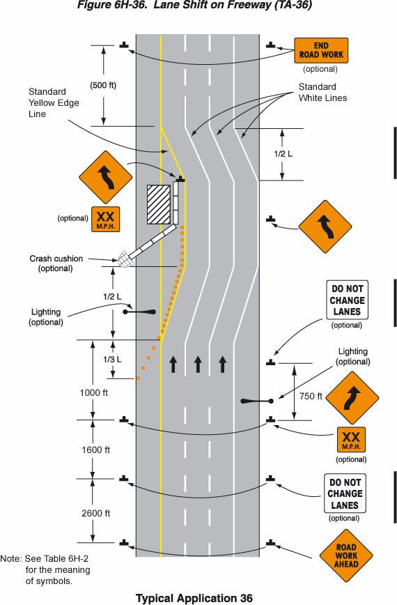
76 Notes for Figure 6H-36 Typical Application 36 Lane Shift on Freeway 1. The lane shift should be used when the work space extends into either the right or left lane of a divided highway and it is not practical, for capacity reasons, to reduce the number of available lanes. 2. When a lane shift is accomplished by using (1) geometry that meets the operational speed at which the permanent highway was designed, (2) full normal cross-section (full lane width and full shoulders), and (3) complete pavement markings, then only the initial general workzone warning sign is required. 3. When the conditions in Note 2 are not met, the information shown in the typical application should be employed and all the following notes apply. Standard: 4. A warning sign shall be used to show the changed alignment. 5. Where the shifted section is longer than 180 m (600 ft), one set of Reverse Curve signs should be used to show the initial shift and a second set should be used to show the return to the normal alignment. If the tangent distance along the temporary diversion is less than 180 m (600 ft), the Winding Road sign should be used instead of the first Reverse Curve sign. The second Reverse Curve sign should be omitted. 6. If a STAY IN LANE sign is used, then solid white lane lines should be used. Standard: 7. The minimum width of the shoulder lane shall be 3 m (10 ft). 8. For long-term stationary work, existing conflicting pavement markings shall be removed and temporary markings shall be installed before traffic patterns are changed. Option: 9. For short-term stationary work, lanes may be delineated by channelizing devices or removable pavement markings instead of temporary pavement markings. 10. Triple Lane Shift signs may be used in place of the Reverse Curve signs. ALL LANES THRU supplemental plaques may be used to emphasize the point that all lanes shift and no lanes are closed. 11. If the shoulder cannot adequately accommodate trucks, trucks may be directed to use the travel lanes. 12. The barrier shown in this typical application is one method that may be used to close a lane for a long-term project (see Section 6F.75 for end treatments). 13. The use of a barrier should be based on engineering judgment. Option: 14. Type C Steady-Burn warning lights may be placed on channelizing devices and the barrier parallel to the edge of pavement for nighttime lane closures. 6H-76
77 6H-77
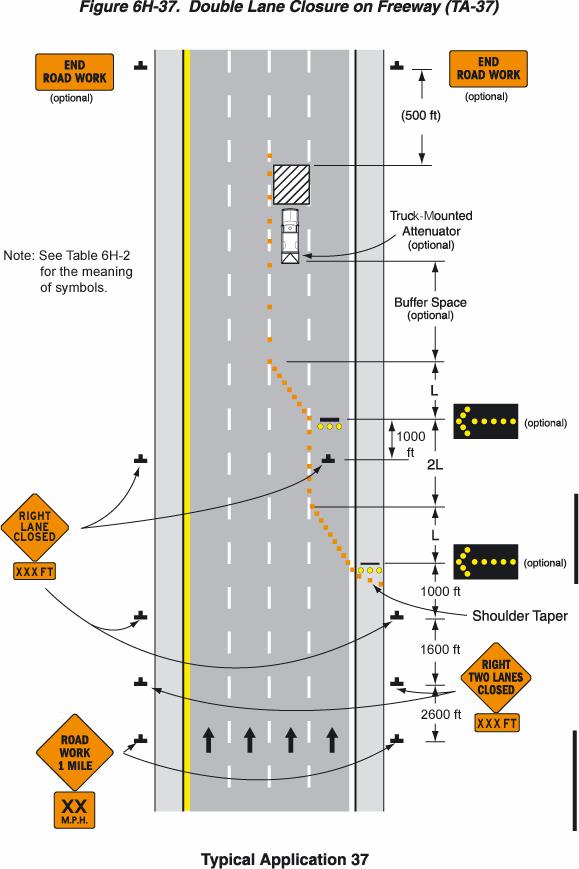
78 Notes for Figure 6H-37 Typical Application 37 Double Lane Closure on Freeway 1. Ordinarily, the preferred position for the second arrow panel is in the closed interior lane at the beginning of the second merging taper. However, the second arrow panel should be placed in the closed exterior lane at the end of the second merging taper in the following situations: Option: a. When a shadow vehicle is used in the interior closed lane, and the second arrow panel is mounted on the shadow vehicle; b. If alignment or other conditions create any confusion as to which lane is closed by the second arrow panel; and c. When the first arrow panel is placed in the closed exterior lane at the end of the first merging taper (the alternative position when the shoulder is narrow). 2. Flashing warning lights and/or flags may be used to call attention to the initial warning signs. 3. A truck-mounted attenuator may be used on the shadow vehicle. 4. If a paved shoulder having a minimum width of 3 m (10 ft) and sufficient strength is available, the left and center lanes may be closed and motor vehicle traffic carried around the work space on the right lane and a right shoulder. 5. If the shoulder cannot adequately accommodate trucks, trucks may be directed to use the travel lanes. 6H-78
79 6H-79
80 Figure 6H-38 - DELETED 6H-80
81 Figure 6H-38 - DELETED 6H-81
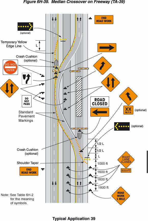
82 Notes for Figure 6H-39 Typical Application 39 Median Crossover on Freeway Standard: 1. Channelizing devices or temporary traffic barriers shall be used to separate opposing motor vehicle traffic. 2. For long-term work on high-speed, high-volume highways, consideration should be given to using a temporary traffic barrier to separate opposing motor vehicle traffic. Option: 3. When a temporary traffic barrier is used to separate opposing motor vehicle traffic, the Two- Way Traffic, DO NOT PASS, KEEP RIGHT, and DO NOT ENTER signs may be eliminated. 4. The alignment of the crossover may be designed as a reverse curve. 5. When the crossover follows a curved alignment, the design criteria contained in the AASHTO "Policy on the Geometric Design of Highways and Streets" should be used (see Section 1A.11). 6. When channelizing devices have the potential of leading motor vehicle traffic out of the intended traffic space, the channelizing devices should be extended a distance in meters (feet) of 0.4 times the speed limit in km/h (2 times the speed limit in mph) beyond the end of the transition area as depicted. 7. Where channelizing devices are used, the Two-Way Traffic signs should be repeated every 1.6 km (1 mi). Option: 8. NEXT X KM (MILES) Supplemental Distance plaques may be used with the Two-Way Traffic signs, where X is the distance to the end of the two-way section. Support: 9. When the distance is sufficiently short that drivers entering the section can see the far end of the section, they are less likely to forget that there is opposing motor vehicle traffic. 10. The sign legends for the four pairs of signs approaching the lane closure for the noncrossover direction of travel are not shown. They are similar to the series shown for the crossover direction, except that the left lane is closed. 6H-82
83 6H-83
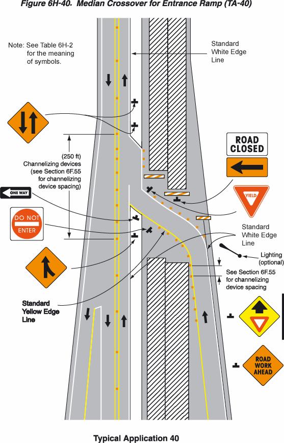
84 Notes for Figure 6H-40 Typical Application 40 Median Crossover for Entrance Ramp 1. The typical application illustrated should be used for carrying an entrance ramp across a closed directional roadway of a divided highway. 2. A temporary acceleration lane should be used to facilitate merging. 3. When used, the YIELD or STOP sign should be located far enough forward to provide adequate sight distance of oncoming mainline motor vehicle traffic to select a safe gap. Also, a longer acceleration lane should be provided beyond the sign to reduce the gap size needed. Option: 4. If motor vehicle traffic conditions allow, the ramp may be closed. 5. broken edge line may be carried across the temporary entrance ramp to assist in defining the through motor vehicle traffic lane. 6. When a temporary traffic barrier is used to separate opposing motor vehicle traffic, the Two- Way Traffic signs and the DO NOT ENTER signs may be eliminated. 6H-84
85 6H-85
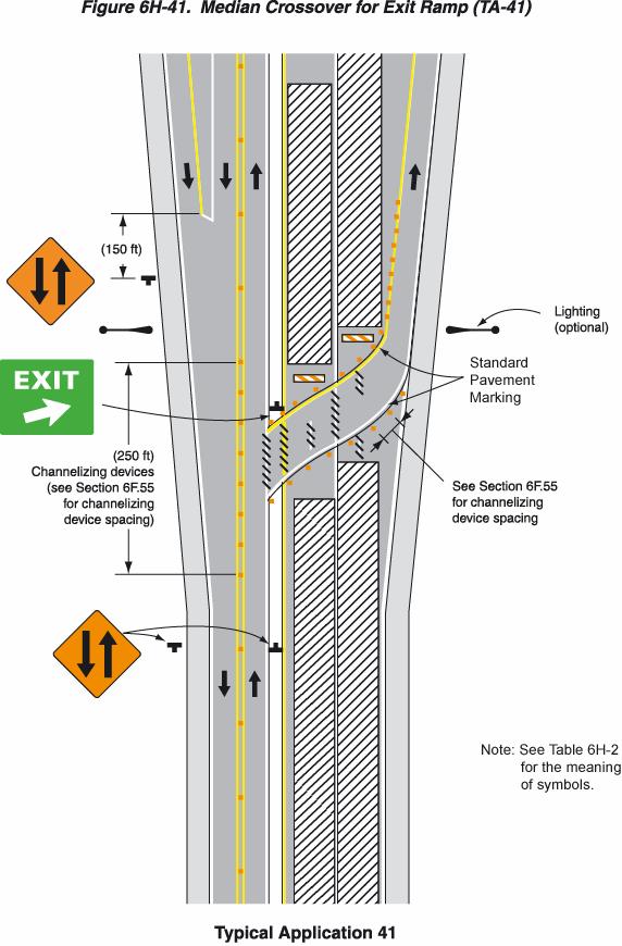
86 Notes for Figure 6H-41 Typical Application 41 Median Crossover for Exit Ramp 1. This typical application should be used for carrying an exit ramp across a closed directional roadway of a divided highway. The design criteria contained in the AASHTO "Policy on the Geometric Design of Highways and Streets" (see Section 1A.11) should be used for determining the curved alignment. 2. The guide signs should indicate that the ramp is open, and where the temporary ramp is located. Conversely, if the ramp is closed, guide signs should indicate that the ramp is closed. 3. A black on orange EXIT CLOSED panel should be placed diagonally across the interchange/intersection guide signs. 4. In the situation (not shown) where channelizing devices are placed along the mainline roadway, the devices' spacing should be reduced in the vicinity of the off ramp to emphasize the opening at the ramp itself. Channelizing devices and/or temporary pavement markings should be placed on both sides of the temporary ramp where it crosses the median and the closed roadway. 5. Advance guide signs providing information related to the temporary exit should be relocated or duplicated adjacent to the temporary roadway. Standard: 6. A temporary EXIT sign shall be located in the temporary gore. For better visibility, it shall be mounted a minimum of 2.1 m (7 ft) from the pavement surface to the bottom of the sign. Option: 7. Guide signs referring to the exit may need to be relocated to the median. 8. The temporary EXIT sign placed in the temporary gore may be either black on orange or white on green. 9. In some instances, a temporary deceleration lane may be useful in facilitating the exiting maneuver. 10. When a temporary traffic barrier is used to separate opposing motor vehicle traffic, the Two- Way Traffic signs may be omitted. 6H-86
87 6H-87
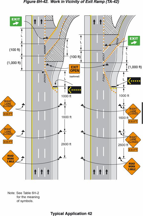
88 Notes for Figure 6H-42 Typical Application 42 Work in Vicinity of Exit Ramp 1. The guide signs should indicate that the ramp is open, and where the temporary ramp is located. However, if the ramp is closed, guide signs should indicate that the ramp is closed. 2. A black on orange EXIT CLOSED panel should be placed diagonally across from the interchange/intersection guide signs. 3. The design criteria contained in the AASHTO "Policy on the Geometric Design of Highways and Streets" should be used for determining the curved alignment (see Section 1A.11). Standard: 4. A temporary EXIT sign shall be located in the temporary gore. For better visibility, it shall be mounted a minimum of 2.1 m (7 ft) from the pavement surface to the bottom of the sign. Option: 5. An alternative procedure is to channelize exiting motor vehicle traffic onto the right shoulder and close the lane as necessary. 6. If a paved shoulder having a minimum width of 3 m (10 ft) and sufficient strength is available, the left and center lanes may be closed and motor vehicle traffic carried around the work space on the right lane and a right shoulder. 7. If the shoulder cannot adequately accommodate trucks, trucks may be directed to use the travel lanes. 8. A buffer may be used. 6H-88
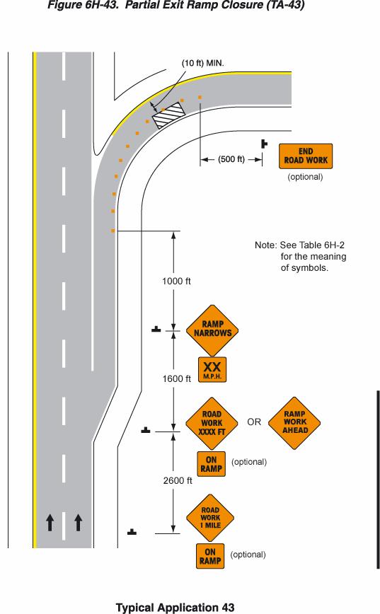
89 6H-89
90 Notes for Figure 6H-43 Typical Application 43 Partial Exit Ramp Closure 1. Truck off-tracking should be considered when determining whether the minimum lane width of 3 m (10 ft) is adequate. 6H-90
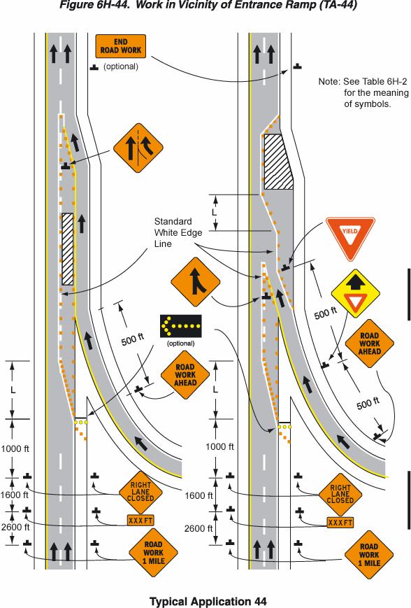
91 6H-91
92 Notes for Figure 6H-44 Typical Application 44 Work in Vicinity of Entrance Ramp 1. An acceleration lane of sufficient length should be provided whenever possible as shown on the left diagram. Standard: 2. For the information shown on the right diagram of the typical application, where inadequate acceleration distance exists for the temporary entrance, the YIELD sign shall be replaced with STOP signs (one on each side of the approach). 3. When used, the YIELD or STOP sign should be located so that ramp motor vehicle traffic has adequate sight distance of oncoming mainline motor vehicle traffic to select a safe gap in the mainline motor vehicle traffic flow. Also, a longer acceleration lane should be provided beyond the sign to reduce the gap size needed. If insufficient gaps are available, consideration should be given to closing the ramp. 4. Where STOP signs are used, a temporary stop line should be placed across the ramp at the desired stop location. 5. The right lane should be closed sufficiently in advance to stabilize motor vehicle traffic flow before encountering the merge. 6. The mainline merging taper with the arrow panel at its starting point should be located sufficiently in advance so that the arrow panel is not confusing to drivers on the entrance ramp, and so that the mainline merging motor vehicle traffic from the lane closure has the opportunity to stabilize before encountering the motor vehicle traffic merging from the ramp. 7. If the ramp curves sharply to the right, warning signs with Advisory Speed Limits located in advance of the entrance terminal should be placed in pairs (one on each side of the ramp). Option: 8. A type B high-intensity warning flasher with a red lens may be placed above the STOP sign. 9. Where the acceleration distance is significantly reduced, a supplemental plaque may be placed below the YIELD AHEAD sign reading NO MERGE AREA. 6H-92
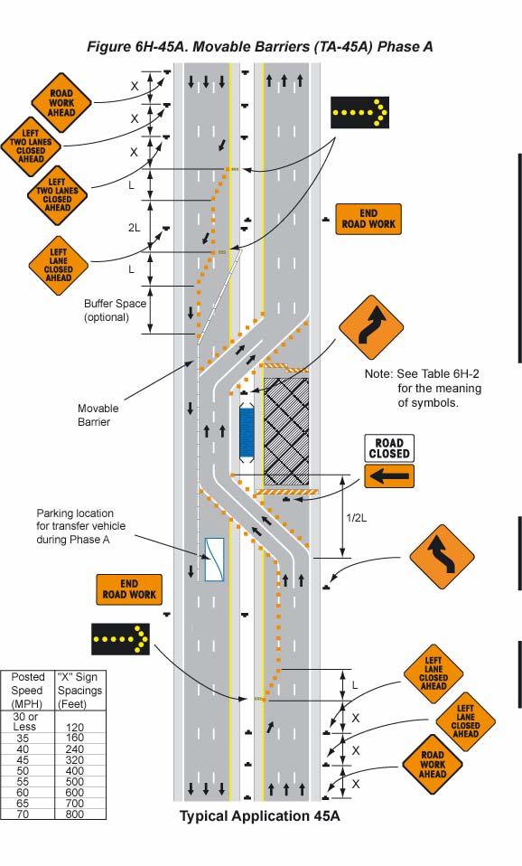
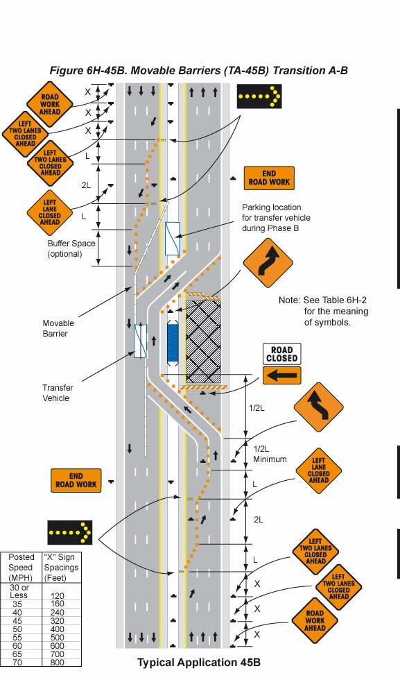
93 6H-93
94 Notes for Figure 6H-45 Typical Application 45 Temporary Reversible Lane Using Movable Barriers Support: 1. This application addresses one of several uses for movable barriers in highway work zones. In this example, one side of a 6-lane divided highway is closed to perform the work operation, and motor vehicle traffic is carried in both directions on the remaining 3-lane roadway by means of a median crossover. To accommodate unbalanced peak-period motor vehicle traffic volumes, the direction of travel in the center lane is switched to the direction having the greater volume, with the transfer typically being made twice daily. Thus, there are four motor vehicle traffic phases described as follows: a. Phase A - two travel lanes northbound and one lane southbound; b. Transition A to B - one travel lane in each direction; c. Phase B - one travel lane northbound and two lanes southbound; and d. Transition B to A - one travel lane in each direction. The typical application on the left illustrates the placement of devices during Phase A. The typical application on the right shows conditions during the transition (Transition A to B) from Phase A to Phase B. 2. For the reversible-lane situation depicted, the ends of the movable barrier should terminate in a protected area or a crash cushion should be provided. During Phase A, the transfer vehicle should be parked behind the end of the movable barrier. During Phase B, the transfer vehicle should be parked behind the end of the movable barrier. The transition shift from Phase A to B should be as follows: a. Change the signs in the northbound advance warning area and transition area from a LEFT LANE CLOSED AHEAD to a LEFT TWO LANES CLOSED AHEAD. b. Place channelizing devices to close the northbound center lane. c. Move the transfer vehicle from south to north to shift the movable barrier from the west side to the east side of the reversible lane. d. Remove the channelizing devices closing the southbound center lane. e. Change the signs in the southbound transition area and advance warning area from a LEFT TWO LANES CLOSED AHEAD to LEFT LANE CLOSED AHEAD. 3. Where the lane to be opened and closed is an exterior lane (adjacent to the edge of the traveled way or the work space), the lane shift should begin by closing the lane with channelizing devices placed along a merging taper using the same information employed for a stationary lane closure. The lane closure should then be extended with the movable-barrier transfer vehicle moving with motor vehicle traffic. When opening the lane, the transfer vehicle should travel against motor vehicle traffic. The 6H-94
95 merging taper should be removed in a method similar to a stationary lane closure. This Page Intentionally Left Blank 6H-95
96 6H-96
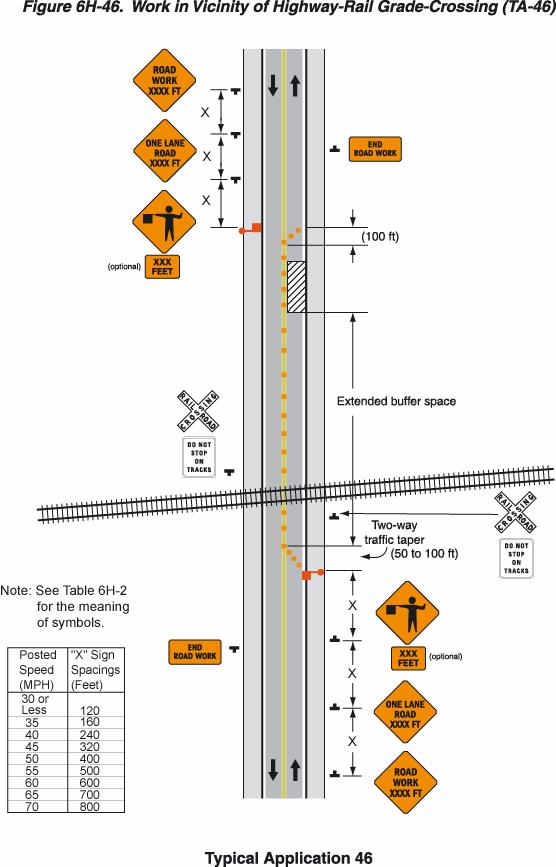
97 6H-97
98 Notes for Figure 6H-46 Typical Application 46 Work in Vicinity of Highway-Rail Grade Crossing 1. When highway-rail grade crossings exist either within or in the vicinity of roadway work activities, extra care should be taken to minimize the probability of conditions being created, either by lane restrictions, flagging or other operations, where vehicles might be stopped within the highway-rail grade crossing, considered as being 4.5 m (15 ft) on either side of the closest and farthest rail. Standard: 2. If the queuing of vehicles across active rail tracks cannot be avoided, a law enforcement officer or flagger shall be provided at the highway-rail grade crossing to prevent vehicles from stopping within the highway-rail grade crossing (as described in Note 1), even if automatic warning devices are in place. 3. Early coordination with the railroad company should occur before work starts. 4. In the example depicted, the buffer space of the activity area should be extended upstream of the highway-rail grade crossing (as shown) so that a queue created by the flagging operation will not extend across the highway-rail grade crossing. 5. The DO NOT STOP ON TRACKS sign should be used on all approaches to a highway-rail grade crossing within the limits of a temporary traffic control zone. Option: 6. Flashing warning lights and/or flags may be used to call attention to the advance warning signs. 7. A BE PREPARED TO STOP sign may be added to the sign series. 8. When used, the BE PREPARED TO STOP sign should be located before the Flagger symbol sign. 9. Lighting should be provided as needed to adequately illuminate flagger stations at night. 6H-98
99 6H-99
Developed by: The American Traffic Safety Services Association (ATSSA) 15 Riverside Parkway, Suite 100 Fredericksburg, VA
 15 Riverside Parkway, Suite 100 Fredericksburg, VA") Addendum Developed by: The American Traffic Safety Services Association (ATSSA) 15 Riverside Parkway, Suite 100 Fredericksburg, VA 22406-1022 800-272-8772 This material is based upon work supported by
Addendum Developed by: The American Traffic Safety Services Association (ATSSA) 15 Riverside Parkway, Suite 100 Fredericksburg, VA 22406-1022 800-272-8772 This material is based upon work supported by
CHAPTER 6H. TYPICAL APPLICATIONS
 2006 Edition Page 6H-1 CHAPTER 6H. TYPICAL APPLICATIONS Section 6H.01 Typical Applications Support: Whenever the acronym TTC is used in this Chapter, it refers to temporary traffic control. Standard: The
Including Revision 1 dated May 2012 and Revision 2 dated May 2012
 Including Revision 1 dated May 2012 and Revision 2 dated May 2012 Page 634 2009 Edition Notes for Figure 6H-1 Typical pplication 1 Work eyond the Shoulder 1. If the work space is in the median of a divided
STREET and UTILITY REPAIRS WORK AREA PROTECTION GUIDE
 STREET and UTILITY REPAIRS WORK AREA PROTECTION GUIDE May 2006 Street and Utility Repairs Work Area Protection Guide TABLE OF CONTENTS 1. Introduction... 1 2. Typical Applications... 11 2.1 Use of Hand-Signaling
Appendix Work Zone Traffic Control
 ppendix Work Zone Traffic Control The purpose of this appendix is to present basic guidelines for work zone traffic control and to supplement the Highway Work Zone Safety Checklist. This appendix presents
MUTCD Part 6G: Type of Temporary Traffic Control Zone Activities
 MUTCD Part 6G: Type of Temporary Traffic Control Zone Activities 6G.01 Typical Applications Each temporary traffic control (TTC) zone is different. Many variables, such as location of work, highway type,
CW20-1D 48" X 48" (Flags- See note 1) G " X 24" (See note 2)
 G X 24 (See note 2)") CK: DW: CK: x for mph or less mph devices may be omitted if the work area is a minimum of from the nearest traveled way. (See notes 4 & 5) x for mph or less Work Space mph x for mph or less mph (See notes
CK: DW: CK: x for mph or less mph devices may be omitted if the work area is a minimum of from the nearest traveled way. (See notes 4 & 5) x for mph or less Work Space mph x for mph or less mph (See notes
CHAPTER 1 STANDARD PRACTICES
 CHAPTER 1 STANDARD PRACTICES OBJECTIVES 1) Functions and Limitations 2) Standardization of Application 3) Materials 4) Colors 5) Widths and Patterns of Longitudinal Pavement Marking Lines 6) General Principles
WORK ZONE TRAFFIC CONTROL PROCEDURES
 WORK ZONE SETUP / REMOVAL WORK ZONE TRAFFIC CONTROL PROCEDURES When installing a work zone, install the advance warning signs on all approaches prior to installing the traffic control devices. Perform
DEFINITIONS Activity Area - Advance Warning Area Advance Warning Sign Spacing Advisory Speed Approach Sight Distance Attended Work Space
 DEFINITIONS Activity Area - that part of a TTC zone activity area where the work actually takes place. It consists of the work space, traffic space and one or more buffer spaces. Advance Warning Area -
Figure 3B-1. Examples of Two-Lane, Two-Way Marking Applications
 Figure 3B-1. Examples of Two-Lane, Two-Way Marking Applications A - Typical two-lane, two-way marking with passing permitted in both directions B - Typical two-lane, two-way marking with no-passing zones
REVOCABLE PERMIT FOR STREET BANNER APPLICATION PACKAGE
 Development Engineering 300 Richards Blvd., 3rd Floor Sacramento, CA 95811 Engineering Services Division REVOCABLE PERMIT FOR STREET BANNER APPLICATION PACKAGE Phone: 916-808-8300 Fax: 916-808-1984 Preparation
2017 Changes to the 2011 MMUTCD January 2017
 2017 Changes to the 2011 MMUTCD January 2017 The design for the Weight Limit symbol sign (R12-5) has been modified to show a threeunit vehicle as the third line of the regulatory weight limit sign. This
(This page left intentionally blank)
") (This page left intentionally blank) 2011 Edition - Revision 1 Page 553 Section 5A.01 Function CHAPTER 5A. GENERAL 01 A low-volume road shall be defined for this Part of the Manual as follows: A. A low-volume
(This page left intentionally blank) 2011 Edition - Revision 1 Page 553 Section 5A.01 Function CHAPTER 5A. GENERAL 01 A low-volume road shall be defined for this Part of the Manual as follows: A. A low-volume
CONSTRUCTION ENCROACHMENT PERMIT APPLICATION AND PROCESSING INSTRUCTIONS
 'HYHORSPHQW (QJLQHHULQJ 5LFKDUGV %OYG UG )ORRU 6DFUDPHQWR &$ Phone: 916-808-8300 Fax: 916-808-1984 (QJLQHHULQJ 6HUYLFHV 'LYLVLRQ CONSTRUCTION ENCROACHMENT PERMIT APPLICATION AND PROCESSING INSTRUCTIONS
NOT TO SCALE PUBLIC WORKS STANDARD DETAILS CURB DETAILS DATE: MARCH 2013 FILE NAME: CURB.DWG
 NOT TO SCALE PUBLIC WORKS STANDARD DETAILS CURB DETAILS DATE: MARCH 2013 FILE NAME: CURB.DWG NOT TO SCALE PUBLIC WORKS STANDARD DETAILS SIDEWALK RAMPS DATE: MARCH 2013 FILE NAME: SIDEWALK RAMPS.DWG NOT
GUIDELINES FOR EMERGENCY TRAFFIC CONTROL
 GUIDELINES FOR EMERGENCY TRAFFIC CONTROL TABLE OF Contents Page Introduction...1 Chapter 6I of the 2009 MUTCD...2 Reason for Control...6 Components of Incident Management Area...7 Traffic Control Devices
PART 5. TRAFFIC CONTROL DEVICES FOR LOW-VOLUME ROADS TABLE OF CONTENTS
 2005 Edition Page TC5-1 PART 5. TRAFFIC CONTROL DEVICES FOR LOW-VOLUME ROADS TABLE OF CONTENTS CHAPTER 5A. Section 5A.01 Section 5A.02 Section 5A.03 Section 5A.04 CHAPTER 5B. GENERAL Page Function...5A-1
Temporary Traffic Control for Highway Work Zones
 Temporary Traffic Control for Highway Work Zones MONTHLY DELMARVA MISS UTILITY MEMBER MEETING MARCH 20, 2014 PRESENTED BY: Adam Weiser, P.E. PTOE Safety Programs Manager Delaware Department of Transportation
CHAPTER 2G. PREFERENTIAL AND MANAGED LANE SIGNS
 2011 Edition - Revision 2 Page 275 Section 2G.01 Scope CHAPTER 2G. PREFERENTIAL AND MANAGED LANE SIGNS 01 Preferential lanes are lanes designated for special traffic uses such as high-occupancy vehicles
Concise Handbook for Temporary Traffic Control - Construction, Maintenance, and Utility Operations
 Purdue University Purdue e-pubs Indiana Local Technical ssistance Program (LTP) Publications Indiana Local Technical ssistance Program (LTP) 5-2016 Concise Handbook for Temporary Traffic Control - Construction,
2003 Edition Page 6F-1
 2003 Edition Page 6F-1 CHAPTER 6F. TEMPORARY TRAFFIC CONTROL ZONE DEVICES Section 6F.01 Types of Devices Whenever the acronym TTC is used in this Chapter, it refers to temporary traffic control. The needs
CHAPTER 6G. TYPE OF TEMPORARY TRAFFIC CONTROL ZONE ACTIVITIES Section 6G.01 Typical Applications
 May 20, 2011 DRAFT 6G-1 CHAPTER 6G. TYPE OF TEMPORARY TRAFFIC CONTROL ZONE ACTIVITIES Section 6G.01 Typical Applications 01 Each TTC zone is different. Many variables, such as location of work, highway
MUTCD Part 6: Temporary Traffic Control
 MUTCD Part 6: Temporary Traffic Control OMUTCD English units are preferred. OHIO MANUAL OF UNIFORM TRAFFIC CONTROL DEVICES TABLE OF CONTENTS PREFACE INTRODUCTION TABLE OF CONTENTS PART 1. GENERAL Chapter
TRAFFIC CONTROL DEVICES FOR LOW VOLUME ROADS
 PART 5. TRAFFIC CONTROL DEVICES FOR LOW VOLUME ROADS TABLE OF CONTENTS Chapter 5A. GENERAL Page Section 5A.1 Function............................................................... 5A-1 5A.2 Application............................................................
Section 3A.04 Colors. Section 3B.10 Approach Markings for Obstructions
 Section 3A.04 Colors Markings shall be yellow, white, red, or blue, or purple. The colors for markings shall conform to the standard highway colors. Black in conjunction with one of the above colors shall
Guidelines for Traffic Control in Work Zones
 Guidelines for Traffic Control in Work Zones pril 2007 Guidelines for Traffic Control in Work Zones Table of Contents Introduction...1 Major Traffic Control Considerations...2 Fundamental Principles...3
New Trends In Temporary Traffic Control (TTC) Spring Occupational Safety & Health Committee Conference Philadelphia, PA
 Spring Occupational Safety & Health Committee Conference Philadelphia, PA") New Trends In Temporary Traffic Control (TTC) Spring Occupational Safety & Health Committee Conference Philadelphia, PA Michael Kelly Work history - Fire service member of 30 years (retired at the rank
New Trends In Temporary Traffic Control (TTC) Spring Occupational Safety & Health Committee Conference Philadelphia, PA Michael Kelly Work history - Fire service member of 30 years (retired at the rank
CHAPTER 3A. GENERAL PAGE CHAPTER 3B. PAVEMENT AND CURB MARKINGS PAGE
 Virginia Supplement to the 2009 MUTCD Revision 1 Page TC-3-1 PART 3. MARKINGS CHAPTER 3A. GENERAL PAGE Section 3A.01 Functions and Limitations Section 3A.02 Standardization of Application Section 3A.03
Sign Designs and Markings Manual (TEM 295-2) Page 8-3
 Page 8-3") Sign Designs and Markings Manual (TEM 295-2) Page 8-3 TEMPORARY TRAFFIC CONTROL SIGNS INDEX Regulatory Signs R1-1 STOP R1-2 YIELD R1-2a TO ONCOMING TRAFFIC R2-1 SPEED LIMIT R2-H2a VEHICLES OVER 4 TONS
Sign Designs and Markings Manual (TEM 295-2) Page 8-3 TEMPORARY TRAFFIC CONTROL SIGNS INDEX Regulatory Signs R1-1 STOP R1-2 YIELD R1-2a TO ONCOMING TRAFFIC R2-1 SPEED LIMIT R2-H2a VEHICLES OVER 4 TONS
Edison Electric Institute. Work Zone Safety October 4-7, 2009
 Edison Electric Institute Work Zone Safety October 4-7, 2009 1 Your Presenter Mike Kelly Fire Department Battalion Chief (Retired 7/05) Member NCUTCD (Chapter 6) Director/Owner of START Group Consultant
REVISION 2 VIRGINIA WORK AREA PROTECTION MANUAL. Ginger Quinn & Paul Kelley April 11, 2018
 REVISION 2 VIRGINIA WORK AREA PROTECTION MANUAL Ginger Quinn & Paul Kelley April 11, 2018 ADA & District Traffic Engineer Added in various sections Work Zone Pedestrian and Bicycle Guidance document VDOT
PERFORMANCE ACTIVITY 405 LIMB MANAGEMENT
 PERFORMANCE ACTIVITY 405 LIMB MANAGEMENT 405 LIMB MANAGEMENT ACTIVITY DESCRIPTION Cut and/or remove and/or grind tree limbs from the right-of-way. TRAFFIC CONTROL Utilize intermittent mobile operations
Guide for Law Enforcement Personnel in Work Zones
 Guide for Law Enforcement Personnel in Work Zones Table of Contents Introduction........................... 3 Roles and Responsibilities................ 5 Most Common Law Enforcement Services in Work
TEMPORARY TRAFFIC CONTROL
 (MI) PART 6 TEMPORARY TRAFFIC CONTROL CHAPTER 6A GENERAL Section 6A.01 General... 547 CHAPTER 6B FUNDAMENTAL PRINCIPLES... 549 CHAPTER 6C TEMPORARY TRAFFIC CONTROL ELEMENTS...551............ 554... 554...
PART 6. TEMPORARY TRAFFIC CONTROL CHAPTER 6A. GENERAL
 2012 Edition Page 623 Section 6A.01 General PART 6. TEMPORARY TRAFFIC CONTROL CHAPTER 6A. GENERAL 01 Whenever the acronym TTC is used in Part 6, it refers to temporary traffic control. 02 The needs and
(This page left intentionally blank)
") (This page left intentionally blank) 2011 Edition - Revision 2 Page 569 Section 6A.01 General PART 6 TEMPORARY TRAFFIC CONTROL CHAPTER 6A. GENERAL 01 Whenever the acronym TTC is used in Part 6, it refers
(This page left intentionally blank) 2011 Edition - Revision 2 Page 569 Section 6A.01 General PART 6 TEMPORARY TRAFFIC CONTROL CHAPTER 6A. GENERAL 01 Whenever the acronym TTC is used in Part 6, it refers
CHAPTER 2B. REGULATORY SIGNS
 CHAPTER 2B. REGULATORY SIGNS Section 2B.01 Application of Regulatory Signs Regulatory signs shall be used to inform road users of selected traffic laws or regulations and indicate the applicability of
2009 Manual on Uniform Traffic Control Devices
 2009 Manual on Uniform Traffic Control Devices Tori Brinkly, PE Highway Safety Engineer WFL-FHWA April 20, 2010 Paragraphs are numbered. Standard Statements are bolded. Guidance statements are italicized.
TRAFFIC CONTROL DEVICES
 TRAFFIC CONTROL DEVICES SIGNS Temporary traffic control work zone signs include regulatory, warning and guide signs utilized to provide regulations, warnings and guidance information to road users impacted
2003 Edition Page 2B-1
 2003 Edition Page 2B-1 CHAPTER 2B. REGULATORY SIGNS Section 2B.01 Application of Regulatory Signs Regulatory signs shall be used to inform road users of selected traffic laws or regulations and indicate
MANUAL ON UNIFORM TRAFFIC CONTROL DEVICES INTRODUCTION
 2011 Edition Page I-1 MANUAL ON UNIFORM TRAFFIC CONTROL DEVICES INTRODUCTION 01 Traffic control devices shall be defined as all signs, signals, markings, and other devices used to regulate, warn, or guide
Accommodating Pedestrians in the Work Zone
 Accommodating Pedestrians in the Work Zone Guidance for Section C Plan Preparers Some impacts cannot be avoided and those impacts apply to residents, businesses, motorists, and pedestrians alike. However,
PART 10. TRAFFIC CONTROLS FOR HIGHWAY-LIGHT RAIL TRANSIT GRADE CROSSINGS TABLE OF CONTENTS
 Part 10. Traffic Controls for Highway-Light Rail Transit Grade Crossings Page 10TC-1 PART 10. TRAFFIC CONTROLS FOR HIGHWAY-LIGHT RAIL TRANSIT GRADE CROSSINGS TABLE OF CONTENTS CHAPTER 10A. GENERAL..........................................
Sign Design Manual (TEM 295-2)
") TEMPORARY TRAFFIC CONTROL SIGNS INDEX Regulatory Signs R1-1 R-1 STOP R1-2 R-2 YIELD R1-2a R-2A TO ONCOMING TRAFFIC R4-1 R-33 DO NOT PASS R4-2 R-34 PASS WITH CARE R4-3 R-35 SLOWER TRAFFIC KEEP RIGHT R4-9
TEMPORARY TRAFFIC CONTROL SIGNS INDEX Regulatory Signs R1-1 R-1 STOP R1-2 R-2 YIELD R1-2a R-2A TO ONCOMING TRAFFIC R4-1 R-33 DO NOT PASS R4-2 R-34 PASS WITH CARE R4-3 R-35 SLOWER TRAFFIC KEEP RIGHT R4-9
ADA on Construction. Guidance for Section C Plan Preparers
 ADA on Construction Guidance for Section C Plan Preparers Some impacts cannot be avoided and those impacts apply to residents, businesses, motorists, and pedestrians alike. However, good planning can minimize
Traffic Control Devices
 533372 Highway Engineering Traffic Control Devices Traffic Control Devices o The media by which traffic engineers communicate with drivers o Every traffic law, regulation, or operating instruction must
MUTCD Part 6D: Pedestrian and Worker Safety
 MUTCD Part 6D: Pedestrian and Worker Safety Section 6D.01 Pedestrian and Worker Safety The needs and control of all road users (motorists, bicyclists, and pedestrians) within the highway, including persons
CURBSIDE ACTIVITY DESIGN
 5 CURBSIDE ACTIVITY DESIGN This chapter provides design guidance for separated bike lanes adjacent to curbside activities including parking, loading and bus stops. Typical configurations are presented
Signs. signs, signals and road markings. in this chapter
 3 signs, signals and road markings in this chapter Signs regulatory signs school, playground and crosswalk signs lane use signs turn control signs parking signs reserved lane signs warning signs object
SECTION TRAFFIC REGULATIONS
 SECTION 01550 TRAFFIC REGULATIONS PART 1 - GENERAL 1.01 OBJECTIVES A. The Contractor shall provide for safe movement of vehicular, bicycle and pedestrian traffic, including persons with disabilities in
TEMPORARY TRAFFIC CONTROL ELEMENTS
 PART 6. TEMPORARY TRAFFIC CONTROL TABLE OF CONTENTS Page CHAPTER 6A. Section 6A.01 CHAPTER 6B. GENERAL General...6A-1 FUNDAMENTAL PRINCIPLES Section 6B.01 Fundamental Principles of Temporary Traffic Control...
TRAFFIC ACCOMMODATION IN WORK AREAS
 TRAFFIC ACCOMMODATION IN WORK AREAS TRAFFIC ACCOMMODATION IN WORK AREAS Copyright 2005 All rights reserved. Reproduction of this document in whole or in part by any means is prohibited, unless authorized
Part 8. TRAFFIC CONTROL FOR RAILROAD AND LIGHT RAIL TRANSIT GRADE CROSSINGS
 Part 8. TRAFFIC CONTROL FOR RAILROAD AND LIGHT RAIL TRANSIT GRADE CROSSINGS TABLE OF CONTENTS MN Rev. 6 MN Rev. 6 MN Rev. 6 Chapter 8A. GENERAL Page Section 8A.1 Introduction............................................................
CHAPTER 2F. TOLL ROAD SIGNS. Table 2F-1. Toll Road Sign and Plaque Minimum Sizes
 2011 Edition Page 249 Section 2F.01 Scope CHAPTER 2F. TOLL ROAD SIGNS 01 Toll highways are typically limited-access freeway or expressway facilities. A portion of or an entire route might be a toll highway,
Section 9A.07 Meaning of Standard, Guidance, Option, and Support
 2012 Edition Page 895 PART 9. TRAFFIC CONTROLS FOR BICYCLE FACILITIES CHAPTER 9A. GENERAL Section 9A.01 Requirements for Bicyclist Traffic Control Devices 01 General information and definitions concerning
Chapter #4 Traffic Control Devices and Laws
 Chapter #4 Traffic Control Devices and Laws Chapter #4 Overview Unit 4 will introduce the student to traffic control devices, including signs, signals and pavement markings, as well as traffic laws specific
Traffic Signs and Signals
 CHAPTER FOUR Traffic Signs and Signals Traffic signs control traffic flow, making streets and highways safer for drivers, bicyclists and pedestrians. These signs, which are posted by the Indiana Department
Attachment No. 13. National Committee on Uniform Traffic Control Devices RWSTC RECOMMENDATION FOLLOWING SPONSOR COMMENTS
 1 2 3 4 Attachment No. 13 5 6 7 8 9 10 11 12 13 14 15 16 17 18 19 20 21 22 23 24 25 26 27 28 29 30 31 32 33 34 35 36 37 38 39 40 41 42 43 RWSTC agenda item IV. 2 June 2011 National Committee on Uniform
TRAFFIC LINE MANUAL. June 2011 TRAFFIC-ROADWAY SECTION
 TRAFFIC LINE MANUAL TRAFFIC-ROADWAY SECTION TABLE OF CONTENTS Foreword...iv Section A: General Principles A-1 Functions and Limitations... 1 A-2 Colors... 1 A-3 Colored Pavements... 1 A-4 Functions, Widths,
WORK ZONE TRAFFIC CONTROL & SAFETY
 WORK ZONE TRAFFIC CONTROL & SAFETY Purpose of Temporary Traffic Control 1. Warn motorists and pedestrians of hazards. 2. Advise proper travel path. 3. Delineate areas not to be used. 4. Separate the travel
INTERSECTIONS AT GRADE INTERSECTIONS
 INTERSECTIONS 1 AT GRADE INTERSECTIONS INTERSECTIONS INTERSECTIONS = INTERRUPTED FACILITIES Definitions and key elements An intersection is defined as an area where two or more roadways join or cross.
PART 7. TRAFFIC CONTROLS FOR SCHOOL AREAS CHAPTER 7A. GENERAL
 2012 Edition Page 825 Section 7A.01 Need for Standards January 13, 2012 PART 7. TRAFFIC CONTROLS FOR SCHOOL AREAS CHAPTER 7A. GENERAL 01 Regardless of the school location, the best way to achieve effective
Guidelines for Temporary Traffic Control in Work Zones
 Guidelines for Temporary Traffic Control in Work Zones ugust, 2008 Guidelines for Traffic Control in Work Zones Table of Contents Introduction...1 Major Traffic Control Considerations...2 Fundamental Principles...3
Plan prepared for: Brennan Paving and Construction. Plan prepared by: Direct Traffic Management
 Traffic Control Plan Hwy 401 - Bridgeland Avenue / Site 37-283 Grading, Drainage, Garnular Base, Hot Mix Paving, Electrical, Structural and Plan prepared for: Plan prepared by: General Notes WB 401 Collector
MINNESOTA FLAGGING HANDBOOK
 MINNESOTA FLAGGING HANDBOOK January, 2018 Flagging Handbook This Flagging Handbook has been developed following the guidelines of the 2011 edition of the Minnesota Manual on Uniform Traffic Control Devices,
PERFORMANCE ACTIVITY 306 DRAINAGE PIPE WORK DESCRIPTION 4
 PERFORMANCE ACTIVITY 306 DRAINAGE PIPE WORK DESCRIPTION 1 WORK DESCRIPTION 2 WORK DESCRIPTION 3 WORK DESCRIPTION 4 Repair Install Remove Clean 306 DRAINAGE PIPE ACTIVITY DESCRIPTION Install, repair, clean,
Temporary Traffic Control Handbook
 InTrans Project Reports Institute for Transportation 3-2016 Temporary Traffic Control Handbook Paul Wiegand Iowa State University, pwiegand@iastate.edu Beth Richards Iowa State University, brich@iastate.edu
SECTION 12 ROAD MARKINGS AND DELINEATION
 SECTION 12 ROAD MARKINGS AND DELINEATION (Blank Page) MANUAL OF TRAFFIC SIGNS AND MARKINGS - Part III: Motorways and Expressways 12-1 12.1 GENERAL 12.1.1 INTRODUCTION The markings and delineation details
Chapter 2B. REGULATORY SIGNS
 Chapter 2B. REGULATORY SIGNS TABLE OF CONTENTS Chapter 2B. Regulatory Signs Page Section 2B.1 Application of Regulatory Signs............................................ 2B-1 2B.2 Design of Regulatory
November 2012: The following Traffic and Safety Notes were revised:
 CHANGE LIST for MDOT Traffic and Safety, TRAFFIC AND SAFETY NOTES Located at http://mdotcf.state.mi.us/public/tands/plans.cfm JANUARY 2014: The following Traffic and Safety Note was added: Note 705A Angled
TRAFFIC CONTROLS FOR BICYCLE FACILITIES
 Part 9. TRAFFIC CONTROLS FOR BICYCLE FACILITIES TABLE OF CONTENTS Chapter 9A. GENERAL Page Section 9A.1 Requirements for Bicyclist Traffic Control Devices............................. 9A-1 9A.2 Scope.................................................................
CHAPTER 2B. REGULATORY SIGNS, BARRICADES, AND GATES Section 2B.01 Application of Regulatory Signs Standard:
 2011 Edition Page 45 CHAPTER 2B. REGULATORY SIGNS, BARRICADES, AND GATES Section 2B.01 Application of Regulatory Signs 01 Regulatory signs shall be used to inform road users of selected traffic laws or
Off-road Trails. Guidance
 Off-road Trails Off-road trails are shared use paths located on an independent alignment that provide two-way travel for people walking, bicycling, and other non-motorized users. Trails specifically along
Appendix C. TRAFFIC CALMING PROGRAM TOOLBOX
 Appendix C. TRAFFIC CALMING PROGRAM TOOLBOX PHASE I...2 Do Not Enter Sign...3 One-Way Sign...4 Turn Prohibition...5 Pavement Markings...6 Speed Monitoring Trailer...7 Neighborhood Speed Watch...8 Police
Minnesota Manual on Uniform Traffic Control Devices
 Minnesota Manual on Uniform Traffic Control Devices MN MUTCD January 2014 MINNESOTA MANUAL ON UNIFORM TRAFFIC CONTROL DEVICES MN MUTCD January 2014 Minnesota Department of Transportation Office of Traffic,
Oregon Supplement to the Manual on Uniform Traffic Control Devices. Adopted July 2005 by OAR
 Oregon Supplement to the Manual on Uniform Traffic Control Devices Adopted July 2005 by OAR 734-020-0005 2003 Edition Oregon Supplement to the MUTCD Page 2 INTRODUCTION Traffic control devices installed
TRAFFIC LINE MANUAL Edition Revision 1 June 2012 TRAFFIC-ROADWAY SECTION
 TRAFFIC LINE MANUAL 2011 Edition Revision 1 June 2012 TRAFFIC-ROADWAY SECTION TABLE OF CONTENTS Foreword...iv Section A: General Principles A-1 Functions and Limitations... 1 A-2 Colors... 1 A-3 Colored
Part 6 TEMPORARY TRAFFIC CONTROL. March 16, 2011
 Part 6 TEMPORARY TRAFFIC CONTROL March 16, 2011 Delaware MUTCD 2 Federal MUTCD published in Dec. 2009 DE MUTCD committee began meeting in Jan. 2010 to establish DE-specific guidance DE MUTCD submitted
Ohio Department of Transportation Edition of the OMUTCD It s Here!
 Ohio Department of Transportation John R. Kasich, Governor Jerry Wray, Director 2012 Edition of the OMUTCD It s Here! June 6, 2012 Here are reasons why we have a Manual of Uniform Traffic Control Devices
Attachment No. 17 GMI No. 1. National Committee on Uniform Traffic Control Devices GMI SIGNS TECHNICAL COMMITTEE RECOMMENDATION
 1 2 3 Attachment No. 17 GMI No. 1 4 5 6 7 8 9 10 11 12 13 14 15 16 17 18 19 20 21 22 23 24 25 26 27 28 29 30 31 32 33 34 35 36 37 GMI agenda item II.H.2., January 19, 2012 National Committee on Uniform
Module 1: Work Zone Traffic Control
 Module 1: Work Zone Traffic Control Overview of Module 1 Underlying principles of work zone traffic control Manual of Uniform Traffic Control Device (MUTCD) Features of work zone traffic control Hazards
Errata Date February 2016 Errata Edition Field. Ontario Traffic Manual Book 7 Field Edition (FE) - ERRATA
 - ERRATA") Errata Date February 2016 Errata Edition Field Ontario Traffic Manual Book 7 Field Edition (FE) - ERRATA Errata Reference Number Item Number 100 Page No. 39 Errata 7FE/001/16 The first bullet point under
Errata Date February 2016 Errata Edition Field Ontario Traffic Manual Book 7 Field Edition (FE) - ERRATA Errata Reference Number Item Number 100 Page No. 39 Errata 7FE/001/16 The first bullet point under
(This page left intentionally blank)
") (This page left intentionally blank) 2011 Edition - Revision 2 Page 771 Section 8A.01 Introduction PART 8 TRAFFIC CONTROL FOR RAILROAD AND LIGHT RAIL TRANSIT GRADE CROSSINGS CHAPTER 8A. GENERAL 01 Whenever
(This page left intentionally blank) 2011 Edition - Revision 2 Page 771 Section 8A.01 Introduction PART 8 TRAFFIC CONTROL FOR RAILROAD AND LIGHT RAIL TRANSIT GRADE CROSSINGS CHAPTER 8A. GENERAL 01 Whenever
Beginning School Bus Driver Curriculum UNIT IX. FIELD TRIPS and TRAFFIC CONTROL DEVICES. Revised 09/2011 Revised 10/2013 (Instructional Content)
") Beginning School Bus Driver Curriculum UNIT IX FIELD TRIPS and TRAFFIC CONTROL DEVICES Revised 09/2011 Revised 10/2013 (Instructional Content) Unit IX FIELD TRIPS AND TRAFFIC CONTROL DEVICES TABLE OF CONTENTS
Beginning School Bus Driver Curriculum UNIT IX FIELD TRIPS and TRAFFIC CONTROL DEVICES Revised 09/2011 Revised 10/2013 (Instructional Content) Unit IX FIELD TRIPS AND TRAFFIC CONTROL DEVICES TABLE OF CONTENTS
City of Albert Lea Policy and Procedure Manual 4.10 ALBERT LEA CROSSWALK POLICY
 4.10 ALBERT LEA CROSSWALK POLICY PURPOSE: Pedestrian crosswalks are an integral part of our transportation infrastructure. To be effective and promote safety, marked crosswalks must be installed after
Traffic Signs and Markings. Instructor: Dr. Yahya Sarraj Associate Prof. Of Transportation
 and Markings Instructor: Dr. Yahya Sarraj Associate Prof. Of Transportation Definition; A traffic sign is defined as a device mounted on a fixed or portable support whereby a specific message is conveyed
Traffic Control Inspection Checklist Segment:
 Traffic Control Inspection Checklist Segment: Simon Contractors Simon Contractors Originator: Description Reviewed by: Initials Date Distribution: Traffic Quality Manager, Site Assistant Traffic Manager
ATTACHMENT NO. 18 GMI-C. National Committee on Uniform Traffic Control Devices GMI SIGNS TECHNICAL COMMITTEE RECOMMENDATION
 1 2 3 ATTACHMENT NO. 18 GMI-C 4 5 6 7 8 9 10 11 12 13 14 15 16 17 18 19 20 21 22 23 24 25 26 27 28 29 30 31 32 33 34 35 36 37 38 39 GMI agenda item II.H.2., January 19, 2012 National Committee on Uniform
Alberta Infrastructure HIGHWAY GEOMETRIC DESIGN GUIDE AUGUST 1999
 Alberta Infrastructure HIGHWAY GEOMETRIC DESIGN GUIDE AUGUST 1999,1'(; A ACCELERATION Data on acceleration from stop D-29 Effects of grade D-35 Intersections D-97, D-99 Lanes D-97, F-5, F-7, F-15, F-21,
10.0 CURB EXTENSIONS GUIDELINE
 10.0 CURB EXTENSIONS GUIDELINE Road Engineering Design Guidelines Version 1.0 March 2017 City of Toronto, Transportation Services City of Toronto Page 0 Background In early 2014, Transportation Services
Road Markings. Lecture Notes in Transportation Systems Engineering. Prof. Tom V. Mathew
 Road Markings Lecture Notes in Transportation Systems Engineering Prof. Tom V. Mathew 1 Overview The essential purpose of road markings is to guide and control traffic on a highway. They supplement the
MEMORANDUM. Date: 9/13/2016. Citywide Crosswalk Policy
 MEMORANDUM Date: 9/13/2016 Re: Citywide Crosswalk Policy Foreword Through the s Circulation Element and Complete Streets Policy, it is the City s goal to promote walking trips and provide safe facilities
CIRCULAR NO. O-13. Recommended Practices for Manual Protection of Highway/Railway Grade Crossings
 CIRCULAR NO. O-13 Recommended Practices for Manual Protection of Highway/Railway Grade Crossings Effective: October 1, 2004 CONTENTS 1. SCOPE 2. GENERAL PRINCIPLES 3. DEFINITIONS 4. PROTECTION REQUIRED
INDEX. Geometric Design Guide for Canadian Roads INDEX
 Acceleration lane, see Lanes, Acceleration Access, 8.1 Access Management and Functional Classification 8.2 Access Management by Design Classification 8.3 Access Configuration 8.4 Building Set-Back Guidelines
(This page left intentionally blank)
") (This page left intentionally blank) 2011 Edition- Revision 2 Page 813 CHAPTER 9A. GENERAL Section 9A.01 Requirements for Bicyclist Traffic Control Devices 01 General information and definitions concerning
(This page left intentionally blank) 2011 Edition- Revision 2 Page 813 CHAPTER 9A. GENERAL Section 9A.01 Requirements for Bicyclist Traffic Control Devices 01 General information and definitions concerning
Access Location, Spacing, Turn Lanes, and Medians
 Design Manual Chapter 5 - Roadway Design 5L - Access Management 5L-3 Access Location, Spacing, Turn Lanes, and Medians This section addresses access location, spacing, turn lane and median needs, including
TEMPORARY TRAFFIC CONTROL GUIDELINES FOR HIGHWAY-RAIL GRADE CROSSINGS
 TEMPORARY TRAFFIC CONTROL GUIDELINES FOR HIGHWAY-RAIL GRADE CROSSINGS 1.0 INTRODUCTION 1.1 Purpose The Southern California Regional Rail Authority (SCRRA) is the designated track owner of the Metrolink
Minnesota Manual on Uniform Traffic Control Devices
 Minnesota Manual on Uniform Traffic Control Devices MN MUTCD February 2018 MINNESOTA MANUAL ON UNIFORM TRAFFIC CONTROL DEVICES MN MUTCD February 2018 Minnesota Manual on Uniform Traffic Control Devices
Roadway Design Manual
 Roadway Design Manual Manual Notice Archive by Texas Department of Transportation (512) 302-2453 all rights reserved Manual Notice 2009-1 From: Manual: Mark A. Marek, P.E Roadway Design Manual Effective