SPARE PART AND OPERATION MANUAL FOOD MIXER Models W30(A), W40(A), W40P, W60(A) and W60P. Form /2009
|
|
|
- Giles Byrd
- 5 years ago
- Views:
Transcription
, W40(A), W40P, W60(A) and")
1 Form /2009 SPARE PART AND OPERATION MANUAL FOOD MIXER Models W30(A), W40(A), W40P, W60(A) and W60P
2 Caution -READ BEFORE OPERATING- Caution Varimixer recommends that mixer operators be at least 18 years of age and be thoroughly trained on the use of the mixer. Varimixer recommends that the following precautions be adopted to help make the mixer operation safer and more efficient....- All operators should be at least 18 years of age. - All operators should be thoroughly trained before being allowed to operate the mixer. - NEVER reach into the bowl when the mixer is running. - Do not wear loose clothing or rings while operating the mixer. - Stop the mixer and lower the bowl before adding ingredients, scraping the bowl, removing the...agitator, or removing the product. - Stop the mixer before removing or installing attachments into the drive hub. - Do not attempt to assemble or disassemble attachments while mounted into the drive hub. - Always use the pusher plate with the slicer/meat grinder attachments. - NEVER bypass the safety mechanisms supplied on the mixer. Doing so can cause injury and...is the responsibility of the user to insure these safety mechanisms are operating properly.
3 LIMITED WARRANTY Varimixer warrants its commercial mixers to the original purchaser against defects in material or manufacture for a period of one year from the date of original purchase, subject to the following exclusions and limitations. The warranties provided by Varimixer do not apply in the following instances: EXCLUSIONS 1. In the event that the equipment is improperly installed. Proper installation is the responsibility of the installer, proper installation procedures are covered in the Varimixer Spare Parts and Operations Manual.. 2. In the event that the equipment is improperly maintained. Proper maintenance is the responsibility of the user. Proper maintenance procedures are covered in the Varimixer Spare Parts and Operations Manual. 3. In the event that failure or malfunction of the appliance or any part thereof is caused by abnormal use or is otherwise not attributable to a defect in material or manufacture. 4. In the event that the appliance, by whatever cause, has been materially altered from the condition in which it left the factory. 6. On parts which would normally be worn or replaced under normal conditions.. 7. With regard to adjustments and/or calibrations. Checking of and changes in adjustments and calibrations are the responsibility of the installer, Proper installation is the responsibility of the installer, proper installation procedures are covered in the Varimixer Spare Parts and Operations Manual. If any oral statements have been made regarding the appliance, such statements do not constitute warranties and are not part of the contract of sale. This Limited Warranty constitutes the complete, final and exclusive statement with regard to warranties...this LIMITED WARRANTY IS EXCLUSIVE AND IS IN LIEU OF ALL OTHER WARRANTIES WHETHER....WRITTEN, ORAL OR IMPLIED, INCLUDING, BUT NOT LIMITED TO, ANY WARRANTY OF....MERCHANTABILITY OR FITNESS FOR PARTICULAR PURPOSE OR WARRANTY AGAINST LATENT.... DEFECTS. LIMITATIONS OF LIABILITY In the event of warranty claim or otherwise, the sole obligation of Varimixer shall be the repair and/or replacement at the option of Varimixer, of the appliance or component or part thereof Such repair or replacement shall be the expense of Varimixer except that travel over 100 miles or two hours, overtime, and holiday charges shall be,, the expense of the purchaser. Any repair or replacement under this warranty does not constitute an extension of the origin, warranty for any period for the appliance or for any component part thereof. Parts to be replaced under this warranty will be repaired or replaced at the option of Varimixer with new or functionally operative parts. The liability of Varimixer on any claim of any kind, including claims based on warranty, expressed or implied, contract, negligence, strict liability or any other theories shall be solely and exclusively the repair or replacement of the product as stated herein, an such liability shall not include, and purchaser specifically renounces any rights to recover, special, incidental, consequential or other damages of any kind whatsoever, including, but not limited to, injuries to persons or damage to property, loss of profits or anticipated profits, or loss of use of the product. TO SECURE WARRANTY SERVICE If you claim a defect covered by this Limited Warranty, first direct your claim to the local Authorized Service Agency, giving model, serial and code numbers, voltage, a description of the problem and your sales slip. If this procedure fails to be satisfactory to you, you may write to the Varimixer National Service Manager, 5489 Campus Dr, Shreveport, Louisiana 71129; you should include the information listed above.
4 TABLE OF CONTENTS Installation Instructions...2 Operating Instructions...3 Cleaning-Maintenance...4 Belt Adjustments and Removal...5 Adjusting the Bowl Height...7 Machine Column...9 Bowl Arms...11 Planetary Head...13 Transmission...15 Speed Lever Assembly...17 Single Speed Transmission...19 Attachment Drive...21 Instrument Panel...23 Bowl Screen...27 Bowl Scraper...29 Tools and Bowls...33 Bowl Truck...33 Electrical Diagrams

5 Read this page entirely BEFORE beginning installation. VARIMIXER INSTALLATION INSTRUCTIONS UNDER NO CIRCUMSTANCES ARE THE SPEED LEVER, BOWL LIFT LEVER, OR THE BOWL ARMS TO BE USED TO MOVE THE MIXER INTO PLACE. DAMAGE WILL RESULT TO THE UNIT. IT IS RECOMMENDED THAT THE TOP LID BE REMOVED BEFORE MOVING THE UNIT. The mixer must be mounted with the rubber feet, which neutralize both shaking and rusting. Spacers can be inserted under the mixer s feet if the floor is uneven. The mixer can be bolted to the floor if d esired. Before the mixer is connected to power, it should be checked that the voltage and frequency on the rating plate is correct in relation to the place of installation. A unit labeled 220V 3 Phase will operate from 208V to 240V 3 phase safely. The rating plate is located on the rear right side of the mixer. The electrical connection box is located at the top rear of the mixer. WARNING Electrical and grounding connections must comply with applicable portions of the National Electrical Code and/or other local electrical codes...ire Wire Color Codes White-Phase 1 Red -Phase 2 Black-Phase 3 Green-Ground No Neutral is used 1. Lower the bowl lift lever. 2. Remove the bowl and all tools. 3. Raise the bowl lift. 4. Close bowl screen if equipped. 5. Turn timer to 10 minutes and push start. 6. Insure cover is rotating in the correct direction. 2
6 OPERATION OF THE MIXER: A) Open the bowl screen and place the bowl in the bowl arms. Note: The bowl arms must be in lowest position and the bowl must be pushed all the way into the bowl arms. (Fig.3). B) Place the mixing tool in the bayonet shaft. The pin on the tool must be turned into the bayonet hole (fig.2). C) The bowl is raised to working position, ensure that the bowl is placed correctly. Close the bowl screen. If the mixer is equipped with a timer, set the mixing time required by turning the timer (fig 1) clockwise. The mixer will stop automatically, when the time runs out. When the mixer has timed out, the "procedure for starting after emergency stop" is used before the mixer is re-started. D) Start the mixer by pressing the green start button (fig.1) The mixer will only start when the bowl is in the "up" position, the bowl screen is "closed", and the timer is set to time or "hold". E) Turn the speed selector lever (fig. 4) to the rear until the required speed has been obtained, (notice the recommended maximum speeds on page 3). F) Before the mixer is stopped, the speed selector lever must be moved back to lowest speed (fig.4). G) Stop the mixer by pressing the red stop button (fig.1) PROCEDURE FOR STARTING AFTER EMERGENCY STOP: 1) This procedure must be used in cases where the mixer has been interrupted in high speed. 2) Lower the bowl and remove the tool from the bayonet. 3) Raise the bowl arms, either empty or with the bowl. 4) Close the bowl screen, start the mixer and move the speed selector lever back to lowest speed. Switch off the mixer. Now the mixer can be started as usual. OVERLOAD Do not overload the mixer. Sticky and heavy doughs may reduce the capacity of the bowl by 75%. The capacity is further reduced if the speed of the mixing tool is increased beyond recommended values or if an incorrect mixing tool is used. Large lumps of fat or cooled ingredients MUST be cut into small parts before they are placed into the bowl or damage can occur to the mixing tool(s). 3

7 Correct use of tools: Whips should never be struck against hard objects, this will decrease the life of the tool. Recommended applications for tools: Whip Beater Hook Cakes Waffles Muffins and the like. Cream Egg Whites Mayonnaise and the like. NOTE: Speed should never exceed 150 RPM when using the dough hook. Our dough hook is designed to give you optimum product on low speed. Cleaning: Pizza Bread Donut Doughs and the like. The mixer should be cleaned daily or after use.the mixer should be cleaned with a soft cloth and clean water. Sulphonated soaps should be used with caution as they destroy the mixer's lubricants. Never use high pressure cleaning for the mixer. Bowls and tools of aluminium must not be washed with strong alkaline detergents (ph should not exceed 9.0). The soap suppliers can recommend the correct type of soap. The mixer should be unplugged before cleaning to prevent accidental starting while cleaning. Maintenance and Lubrication: The variable speed pulleys must be lubricated regularly, i.e. a lubrication interval of approx. 60 hours of operation. Lubrication of variable speed pulleys: -Start the mixer and increase the speed to approx. 50%. Stop the mixer and open the lid on the top of the mixer. On the top of each of the two pulley set shafts is a grease nipple (fig. 5 point 1). Press grease through the grease nipples until the grease gun feels hard to press or until grease comes out between the shaft and the pulleys. -Start the mixer, and set the speed back to low..speed. -Stop the mixer and fill the grease gun with new grease so that it is ready for next time. Lubrication of other movable parts: The movable parts of the bowl arms, the shaft and the lifting rod must also be lubricated with oil. Remove the rear covering and lubricate the marked points with an oil can. (fig.5 pkt.2) Grease Types: -Grease for the pulley set shafts: Lubriplate # On repair of the planetary head: Grease the toothed wheel and the toothed rim with Nye Gel 868VH,(PN 868VH), the needle bearings in the planetary head must not be lubricated with this type of grease, they should be lubricated with PN Sapphire 2. Do not use any another type of grease than the one stated here. -On repair of the attachment drive: Fill the attachment drive with Tribol Molub 860/150-0, (PN 860/150-0). Fig.5 The inside of the beater shaft should be cleaned once a day with warm, soapy water. Dough hook Cleaning: Special care should be given to cleaning the dough hook. We recommend that it be cleaned and sanitized in a commercial dish machine. An alternate cleaning procedure is to vigorously scrub the hook with a hot.water and detergent solution. Use a heavy bristled brush. After cleaning, sanitize the hook by rinsing it with a 50 ppm solution of sodium hypochlorite. 4
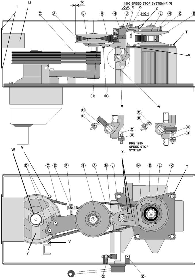
8 Belt Adjustments and Removal To remove V-belts or tooth belt: 1. Remove the 4 screws (T) from the control panel. 2. Remove the front control (U) from mixer and let hang from cables. 3. Open lid. 4. Remove nut (J) and washers (H). 5. Remove fork assembly (X). 6. Roll belt (A) off of the the pulleys and remove. 7. Lossen jam nut (E) and tension bolt (F). 8. Loosen bolts (D). 9. Remove 3 V-belts or single tooth belt from planetary pulley (Y) and pedestal assembly (S). To install V-belts or single tooth belt: 1. Install the 3 V-belts (C) on the pedestal pulley and planetary pulley (Y). 2. Tighten the 2 bolts (D) on the pedestal assembly, insure the v-belts are tight. 3. Install special v-belt (A). 4. Install fork assembly (X). 5. Install washers (G) (H) and nut (J). DO NOT TIGHTEN NUT! 6. On the front pulley set, the stud (K) on the varispeed collar (L) must be placed inside the lower fork (M), and outside...the fork on the rear pulley set (N). 7. Start the mixer and tighten the nut (J). 8. Using the speed adjustment lever, lower the speed until the belt (A) is 1/8 from the outside edge of the front var-... speed pulley (S). THIS IS LOW SPEED. Adjust the 2 jamnuts (R) against the fork (X) and tighten. This is your low... speed setting. 9. Using the speed adjustment lever, increase the speed until the belt (A) is 1/8 from the outside edge of the rear var-... speed pulley (L). THIS IS HIGH SPEED. Adjust the bolt (O) down against the motor plate and tighten the jamnut. This... is the high speed setting. 10. Using the speed adjustment lever, lower the speed to low. Turn off mixer and set the speed indicator arrow to R.P.M. 5
9 6

10 ADJUSTMENT OF BOWL HEIGHT: The distance (X) is measured from the bottom side of the bayonet hole to the surface on the bowl arms on which the bowl rests (fig.7a). The bowl arms must be lifted to normal working position. W30 = 6 3/8 (X): W40 = 6 3/8 W60 = 6 15/16 Lower the bowl arms down on a wooden block so that the weight of the bowl arms are not loading the lifting system. Loosen the counter nut (1), (fig.7b). Take out the cotter pin (2). Take out the lifting rod (3). The lifting bolt (4) is now loose and can be turned out or into the lifting nut (5), until the correct height of the bowl arms has been reached. ADJUSTMENT OF BOWL FIXING: The bowl arms must be raised to normal working position. Loosen the counter nuts (1) and remove the cotter pins (2). Turn the bolt (3) until correct fixing of the bowl is achieved. By turning the bolts out of the extension tube the fixing is increased. Start by turning one of the bolts half a revolution. ADJUSTMENT OF BOWL CENTERING: Loosen the counter nuts (1) and remove the cotter pins (2). Turn the bolt (3) until the bowl is in the center of the mixer. After the fixing of the bowl, one of the bolts must be turned out of the extension tube and the other into the extension tube. Use the flat beater to check that the bowl is correctly centered and turn the planetary head with your hand before the voltage is connected. Fig.7A 7
11 8
12 9 PN PN PN
13 MACHINE COLUMN DESCRIPTION PART NUMBER W30(A) W40(A) W40P W60(A) W60P 1. Bowl Lift Microswitch See Figure See Figure See Figure See Figure See Figure 2. Mounting Screws STA 5270 STA 5270 STA 5270 STA 5270 STA Top Lid Threaded Bushing STA 6580 STA 6580 STA 6580 STA 6580 STA Knee Pad 30N N N N N Intermediate Piece 6 MM 30N N N N N Indicator Arrow Column 30N-22 30N-22 30N-22 60N-22 60N Lift Lever Bushings STA 2515 STA 2515 STA 2515 STA 2515 STA Bowl Arm Shaft Bushings STA 2520 STA 2520 STA 2520 STA 2520 STA Intermediate Piece 3 MM 30N N N N N Foot 30N N N N N Lid Screw STA 5017 STA 5017 STA 5017 STA 5017 STA Access Plate Screw STA 5080 STA 5080 STA 5080 STA 5080 STA Ground Screw STA 5232 STA 5232 STA 5232 STA 5232 STA Rear Access Plate Top Lid Plug Button Rear Screen Plug Button No Hub Upper NSF Plate Cover Lower NSF Plate Cover Lock Nut NSF Plate STA 5834 STA 5834 STA 5834 STA 5834 STA Washer STA 6027 STA 6027 STA 6027 STA 6027 STA Motor Mount M M M M M4 28. Motor Mount Bolt STA 5625 STA 5625 STA 5625 STA 5625 STA Lock Washer STA 6056 STA 6056 STA 6056 STA 6056 STA Roll Pin
14 11
15 BOWL ARMS FIG. NO. DESCRIPTION PART NUMBER W30 (A) W40 (A) W40P W60 (A) W60P 1. Bowl Arm Left (Pre 1993) A. Bowl Arm Right (Pre 1993) B. Bowl Arm Left 30N-23 40N-23 40N-23 60N-23 60N-23 1C. Bowl Arm Right 30N-24 40N-24 40N-24 60N-24 60N Shock Absorber 40P-600M 40P-600M 40P-600M M M 3. Crank Arm Bowl Arm Shaft Lifting Rod Assembly 30-65M 30-65M 30-65M 60-65M 60-65M, 6. Bowl Lift Lever 27-62M 27-62M 27-62M 60-62M 60-62M 7. Extension Tube Assembly 30-69M 30-69M 30-69M 60-69M 60-69M 8. Red Ball STA 3308 ST A3308 STA 3308 STA 3308 STA Key B6 x 6 x 15 STA 2020 STA 2020 STA 2020 STA 2020 STA Washer (s) STA 6044 STA 6044 STA 6044 STA 6044 STA Snap Ring STA 3407 STA 3407 STA 3407 STA 3407 STA Lifting Nut Cotter Pin STA 6205 STA 6205 STA 6205 STA 6205 STA JamNut STA 5827 STA 5827 STA 5827 STA 5827 STA Extension Tube Shoulder Bolt STA 5690 STA 5690 STA 5690 STA 5690 STA Eyebolt Lifting Bolt C-Clip STA 3580 STA 3580 STA 3580 STA 3580 STA Lift Bolt Pin P Bowl Arm Bushing STA 2522 STA 2522 STA 2522 STA 2525 STA Bowl Arm Roller Screw STA 5088 STA 5088 STA 5088 STA 5088 STA Bowl Arm Roller Bowl Arm Roller Shaft Snap Ring STA 3467 STA 3467 STA 3467 STA 3460 STA White Bowl Arm Microswitch Black Bowl Arm Microswitch
16 13 33A
17 FIG. NO A. 1B A. 4B A DESCRIPTION V-Belt (60 HZ) 3 per unit V-Belt (50 HZ) 3 per unit V-Belt Single Cog Belt Snap Ring Washer Planetary Pulley (60 HZ ) Planetary Pulley (50 HZ ) Pulley Single Cog Belt Bearing Snap Ring Bolt M10 x 40 MM Washer Main Bearing Distance Tube Gear Wheel Rim Screw for Grey Cover Planetary Cover Grey Plastic Planetary Head Assembly Plan. Upper Half Assembly Plan. Lower 1/2 Assembly Distance Piece Snap Ring Snap Ring Eccentric Disc Bearing Needle Bearing Key 8 x 7 x 20 mm Upper Rim Pinion Lower Rim Pinion Main Shaft Bearing Race Lower Half Eccentric Head Lockwasher Bolt Seal Needle Bearing w/ race Allen Bolt (if under headcap ) Hex Bolt (if over headcap) Distance Piece Bearing Snap Ring Key(s) Bayonet Shaft S/S Headcap Black Rubber Ring Needle Bearing Grease for *-101 and *-96. Grease for nylon gears PLANETARY HEAD PART NUMBER per MODEL NUMBER W30 (A) W40 (A) W40P W60 (A) (A29) (710LA) STA 3425 STA A STA 3520 STA 5346 STA STA P 30-2M 30-3M M STA 3520 STA STA See Item STA 6055 STA R STA 5641 STA STA 3522 STA D Sapphire 2 868VH (A29) (710LA) STA 3425 STA A STA 3526 STA 5346 STA STA P 40-2M 40-3M M STA 3520 STA STA See Item STA 6057 STA R STA 5646 STA STA 3526 STA D Sapphire 2 868VH (A29) (710LA) 40P-90.1 STA 3425 STA A P-129A STA 3526 STA 5346 STA STA P 40-2M 40-3M M STA 3520 STA STA See Item STA 6057 STA R STA 5646 STA STA 3526 STA D Sapphire 2 868VH (A35) (SPA 850) STA 3427 STA A STA 3528 STA 5346 STA STA P 60-2M 60-3M M STA 3523 STA STA N See Item STA 6057 STA R STA 5650 STA STA 3526 STA 2034 (2) 60-33D Sapphire 2 868VH W60P (A35) STA 3427 STA A STA 3528 STA 5346 STA STA P 60-2M 60-3M M STA 3523 STA STA N See Item STA 6057 STA R STA 5650 STA STA 3526 STA 2034 (2) 60-33D Sapphire 2 868VH 14
18 15
19 FIG. NO A DESCRIPTION Washer Upper Pulley for Pedestal Pin Bearing Lower Pulley Bushing V-Belt Pulley Single Cog Belt Pulley Shaft Key Grease Nipple Snap Ring Bearing Snap Ring Fork Ring Distance Piece Arm for Bearing Bolt Washer Vari-Drive Belt Bearing Reducer (22mm X 1.50) Grease Nipple (12mm x 1.75) Washer Lower Motor Pully Pin for Motor Pulley Lower Motor Pulley Assembly Upper Motor Pulley Assembly Upper Pulley Bushing Fork Ring Clamping Ring Key Motor plate mount screw Screw Motor Mount Plate Rack Bracket Nut Washer Nut Stud Bolt Low Speed Trestle Stop Bolt High Speed Washer Bolt Front Fork Rear Fork Spring Rack Nut Snap Ring Belt Tension Washers Bolt Washer Motor Pulley Assembly Upper Center Pulley Assembly Lower Center Pulley Assembly Center Pulley Assembly TRANSMISSION PART NUMBER per MODEL NUMBER W30 (A) W40 (A) W40P W60 (A) STA M M STA STA 2022 STA 3220 STA STA STA 5348 STA STA 3220 STA 6018 See figure M 15-15M See figure 27 STA STA 2011 STA 5018 STA STA 5812 STA N STA 5444 STA 6010 STA STA 5815 STA 3407 STA 6040 STA 5433 STA M 15-13M 15-15M 27-6M STA M M STA STA 2022 STA 3220 STA STA STA 5348 STA STA 3220 STA 6018 See figure M 15-15M See figure 27 STA STA 2011 STA 5018 STA STA 5812 STA N STA 5444 STA 6010 STA STA 5815 STA 3407 STA 6040 STA 5433 STA M 15-13M 15-15M 27-6M STA M M STA P STA 2022 STA 3220 STA STA STA 5348 STA STA 3220 STA 6018 See figure M 15-15M See figure 27 STA STA 2011 STA 5018 STA STA 5812 STA N STA 5444 STA 6010 STA P STA 5815 STA 3407 STA 6040 STA 5433 STA M 15-13M 15-15M 27-6M STA M M STA STA 2022 STA 3220 STA STA STA 5348 STA STA 3220 STA 6018 See figure M M See figure 27 STA STA 2011 STA 5018 STA STA 5812 STA N STA 5444 STA 6010 STA P STA 5815 STA 3407 STA 6040 STA 5433 STA M 60-13M 60-15M 60-6M W60P STA M M STA STA 2022 STA 3220 STA STA STA 5348 STA STA 3220 STA 6018 See figure M M See figure 27 STA STA 2011 STA 5018 STA STA 5812 STA N STA 5444 STA 6010 STA P STA 5815 STA 3407 STA 6040 STA 5433 STA M 60-13M 60-15M 60-6M 16
20 17
21 SPEED LEVER ASSEMBLY FIG. NO DESCRIPTION Speed Lever Disc with Arrow White Clamp Black Knob Snap Ring Screw PART NUMBER per MODEL NUMBER W30 (A) W40 (A) W40P W60 (A) 30N-47M 30N N STA 3306 STA 3414 STA N-47M 30N N STA 3306 STA 3414 STA N-47M 30N N STA 3306 STA 3414 STA N-47M 30N N STA 3306 STA 3414 STA 5247 W60P 60N-47M 30N N STA 3306 STA 3414 STA
22 Drive System for Model W40PI and W60PI Special Single Speed Transmission-Pizza 18 19
23 FIG. NO DESCRIPTION Motor Pulley Screw Motor Plate Belts Center Pulley Snap Ring Pedestal Shaft Key Pulley Snap Ring Bearing Snap Ring Washer Distance Tube Arm for Bearing Bolt Assembly (Items 6-11) SINGLE SPEED TRANSMISSION W40PI 33V315 STA VX400 33V80 STA STA STA STA 3514 STA STA S-6M W60PI 33V315 STA VX425 33V80 STA STA STA STA 3514 STA STA S-6M PART NUMBER 20
24 33 33A 35 35A 34 34A 21
25 FIG. NO A A A A A. 33B. 33C. 33D. 33E A A. 36. DESCRIPTION Bearing Hub Wormwheel Gear Case Gear Case Cover Worm Gear Gear Shaft Attachment Drive Shaft # 17 Attachment Drive Shaft # 12 Key Bearing Seal Gasket Gasket Gasket Key Key Snap Ring Screw Bearing Bolt Seal Washer Washer Washer Lock Washer Rubber Ring End Cover #17 End Cover #12 Hub #17 Hub #12 Bolt Thumbscrew #17 Thumbscrew #12 Washer Roll Pin #17 Hub Only Motor Mount Plate Motor Pulley Assembly Motor 2HP 1 phase 115V Motor 2HP 1 phase 230V Motor 3HP 3 phase 208V-240V Motor 3HP 3 phase 480V Motor 4HP 3 phase 208V-240V Motor 4HP 3 phase 480V Att. Drive Assembly #17 Att. Drive Assembly #12 Att. Shaft Assembly #17 Att. Shaft Assembly #12 Gear Cover Assembly ATTACHMENT DRIVE GEARBOX PART NUMBER W30 (A) W40 (A) W40P W60 (A) STA Use RTV Silicone Use RTV Silicone Use RTV Silicone STA 2007 STA 2011 STA 3410 STA STA 5433 STA 5908 STA 6020 STA 6054 STA C STA 5322 STA R-125 STA 6056 STA M cccc M M 15-5M 30-5M 15-11M STA Use RTV Use RTV Use RTV STA 2007 STA 2011 STA 3410 STA STA 5433 STA 5908 STA 6020 STA 6054 STA C STA 5322 STA R-125 STA 6056 STA M ccc M M 15-5M 30-5M 15-11M c STA Use RTV Use RTV Use RTV STA 2007 STA 2011 STA 3410 STA STA 5433 STA 5908 STA 6020 STA 6054 STA C STA 5322 STA R-125 STA 6056 STA M c ccc M M 15-5M 30-5M 15-11M STA Use RTV Use RTV Use RTV STA 2007 STA 2011 STA 3410 STA STA 5433 STA 5908 STA 6020 STA 6054 STA C STA 5322 STA R-125 STA 6056 STA M cccc M M 15-5M 30-5M 15-11M W60P STA Use RTV Use RTV Use RTV STA 2007 STA 2011 STA 3410 STA STA 5433 STA 5908 STA 6020 STA 6054 STA C STA 5322 STA R-125 STA 6056 STA M M M 15-5M 30-5M 15-11M 22
26 23
27 FIG. NO a A A. 15B. 15C A. 17B. 17C DESCRIPTION Electrical Control Assembly V 3 Phase Electrical Control Assembly 230V 1 Phase Timer Assembly V Timer Assembly 480V Start Button Green Stop Button Orange Pilot Light Front Panel Timer Scale S crew Timer Knob Screw Cable Inlet Nut Thermal Overload 3 Ph. 220V Thermal Overload 3 Ph. 480V Thermal Overload 1 Ph. 230V Thermal Overload 1 Ph. 115V Auxilary Start Switch Contactor 3 Ph. 220V Contactor 3 Ph. 480V Contactor 1 Ph. 230V Contactor 1 Ph. 115V Screw Screw Plug Button Screw Contactor Bracket ELECTRICAL PANEL JUNE 1998 PART NUMBER W30 (A) W40 (A) W40P W60 (A) 40P-149M M M STA STA 5627 STA 3000 STA STA 5080 STA 5614 STA 6131 STA P-149M M M STA STA 5627 STA 3000 STA STA 5080 STA 5614 STA 6131 STA P-149M M M STA STA 5627 STA 3000 STA STA 5080 STA 5614 STA 6131 STA P-149M M M STA STA 5627 STA 3000 STA STA 5080 STA 5614 STA 6131 STA W60P 40P-149M M M STA STA 5627 STA 3000 STA STA 5080 STA 5614 STA 6131 STA
28 25 19
29 FIG. NO A. 15B. 15C A. 16B. 16C DESCRIPTION Front Panel Start Switch Assembly Stop Switch Assembly Timer Assembly 220V Timer Scale Screw Nut Cable Inlet Cable Inlet Cover Nut Timer Knob Grounding Clamp Screw Contactor 3 Ph. 220V Contactor 3 Ph. 480V Contactor 1 Ph. 230V Contactor 1 Ph. 115V Thermal Overload 3 Ph. 220V Thermal Overload 3 Ph. 480V Thermal Overload 1 Ph. 230V Thermal Overload 1 Ph. 115V Screw Screw Auxiliary Start Switch ELECTRICAL PANEL JULY PRESENT PART NUMBER W30 (A) W40 (A) W40P W60 (A) 30N STA 5232 STA 5897 STA 3000 STA STA STA STA 6483 STA N STA 5232 STA 5897 STA 3000 STA STA STA STA 6483 STA N STA 5232 STA 5897 STA 3000 STA STA STA STA 6483 STA N STA 5232 STA 5897 STA 3000 STA STA STA STA 6483 STA W60P 30N STA 5232 STA 5897 STA 3000 STA STA STA STA 6483 STA
30 27
31 BOWL SCREEN PRESENT FIG. NO DESCRIPTION Bowl Screen Kit Nut Knob Lock Washer Bowl Screen Front Chute Bowl Screen Rear Cam Set Screw Bracket Assembly Screw Nut Microswitch Jam Nut Screw Nut for Bushing Notched Cam Body Bushing PART NUMBER W30 (A) W40 (A) W40P W60 (A) 225/30A STA 5810 STA 3307 STA /30F 56G /30R 56SN30-23 STA P30-15 STA G SN20-30 STA 5819 STA SN SN SN /40A STA 5810 STA 3307 STA /40F 56G /40R 56SN30-23 STA P30-15 STA G SN20-30 STA 5819 STA SN SN SN /40A STA 5810 STA 3307 STA /40F 56G /40R 56SN30-23 STA P30-15 STA G SN20-30 STA 5819 STA SN SN SN /60 STA 5810 STA 3307 STA /60F 56G /60R 56SN30-23 STA P30-15 STA G SN20-30 STA 5819 STA SN SN SN30-21 W60P 225/60 STA 5810 STA 3307 STA /60F 56G /60R 56SN30-23 STA P30-15 STA G SN20-30 STA 5819 STA SN SN SN
32 29
33 BOWL SCRAPER (SCREW TYPE) Fig. No. Description Part Number W30 Part Number W40/40P Part Number W60/60P 1. Scraper Holder 42RN30-101M 42R40-101M 42R60-101M 2. Bowl Scraper 224/30A 224/40A 224/60 3. Bowl Scaper (downsize) 224/15 224/20B 224/30B 4. Holder w/blade 42RN R R Holder w/blade (downsize) 42RN30A R40A R60A Nylon Blade 42RN R R Nylon Blade (downsize) NLA NLA NLA 30
34 31
35 KEYHOLE BOWL SCRAPER Fig. No. Description Part Number W30 Part Number W40/40P Part Number W60/60P 1. Scraper Holder 42R30-101M 42R40-101M 42R60-101M 2. Bowl Scraper 224/30A 224/40A 224/60 3. Bowl Scaper (downsize) 224/15 224/20B 224/30B 4. Holder w/blade 42RN R R Holder w/blade (downsize) 42RN30A R40A R60A Nylon Blade 42RN R R Nylon Blade (downsize) 42RN30A R40A R60A
36 33
37 FIG. NO A DESCRIPTION Stainless Steel Bowl (Standard) Stainless Steel Bowl (Downsize) Dough Hook (Single Pin) Dough Hook (Single Pin,downsize) Tool Pin (Single) Dough Hook (Double Pin) Dough Hook (Single Pin,downsize) Tool Pin (Double) Flat Beater (Aluminum) Flat Beater (Downsize, Aluminum) Tool Pin Wire Whip Wire Whip (Downsize) Wire Whip (Heavy Duty) Wire Whip (Downsize, Heavy Duty) Wing Whip Wing Whip (Downsize) S/S Flat Beater S/S Flat Beater (Downsize) Bowl Truck Bowl Truck (Downsize Bowl) Bowl Truck Handle Plug Button Set Screw Bowl Truck Frame Screw Spacer (For Standard Bowl) Spacer (For Downsize Bowl) Castor Castor f/ Krispy Kreme Bolt Rubber Block (3 per bowl truck) ATTACHMENTS AND OPTIONAL PRODUCTS PART NUMBER W30 (A) W40 (A) W40P W60 (A) 203/30A 203/15 213/30A 213/ /30D 213/ D 205/30A 205/15 STA /30A 207/15 221/30A 209/30A 204/30A 204/15 215/30A 215/15 22R270 STA 6513 STA R30-40 STA R W 22R W 22R R STA /40A 2 03/20A 213/40A 213/20A /40D 213/20B 40-79D 205/40A 205/20B STA /40A 207/20B 221/40A 209/40A 204/40A 204/20B 215/40A 215/20B 22R270 STA 6513 STA R30-40 STA R W 22R W 22R R STA /40A 2 03/20A 213/40A 213/20A /40D 213/20B 40-79D 205/40A 205/20B STA /40A 207/20B 221/40A 209/40A 204/40A 204/20B 215/40A 215/20B 22R270 STA 6513 STA R30-40 STA R W 22R W 22R R STA / /30B 213/60 213/30B /60D 213/30B 60-79D 205/60 205/30B STA /60 207/30B 221/60 221/30B 209/60 209/30B 204/60 204/30B 215/ /30B 22R270 STA 6513 STA R30-40 STA R R W 22R R STA W60P 203/60 203/30B 213/60 213/30B /60D 213/30B 60-79D 205/60 205/30B STA /60 207/30B 221/60 221/30B 209/60 209/30B 204/60 204/30B 215/60 215/30B 22R270 STA 6513 STA R30-40 STA R R W 22R R STA
38 June Phase 35
39 June Phase 36
40 Present 1 Phase 37
41 Present 3 Phase 38
 635-3131 Fax www.varimixer.")
42 5489 Campus Drive Shreveport LA (800) (318) Fax
310 SERIES TILT-TO-LOAD ROTATOR. The Specialist In Drum Handling Equipment
 OPERATOR S MANUAL FOR MORSE TILT-TO-LOAD DRUM ROTATOR SAFETY INFORMATION: While Morse Manufacturing Co. drum handling equipment is engineered for safety and efficiency, a high degree of responsibility
Cocoa Patio Pond with Lit Spillway
 Cocoa Patio Pond with Lit Spillway REMINDER CALL 1-888-755-5641 BEFORE RETURNING TO STORE. PACKAGE CONTENTS ITEM # GQSPPB/GQSPPW Questions, problems, missing parts? Before returning to your retailer, call
Reproduction. Not for 27" & 29" TWO STAGE INTERMEDIATE SNOWTHROWERS Parts Manual for M1227E M1227EX M1529E
 Parts Manual for 27" & 29" TWO STAGE INTERMEDIATE SNOWTHROWERS 2011 Model No. Description 1696001 M1227E 1696002 M1227EX 1696003 M1529E Briggs & Stratton Yard Power Products Group 535 Macon Road McDonough,
DISASSEMBLING & REASSEMBLING CARTRIDGE INSTALLING SEATPOST ON BIKE
 INTRODUCTION BILL OF MATERIALS SPECIFICATIONS & TOOLS PROCEDURES DISASSEMBLING & REASSEMBLING CARTRIDGE INSTALLING SEATPOST ON BIKE OPERATION OF SEATPOST GIANT LIMITED WARRANTY 1 INTRODUCTION Congratulations
Parts Manual STRIKER Striker 2840 Parts List - PN Printed in USA 03/18/08
 Parts Manual STRIKER 2840 Striker 2840 Parts List - PN 238155 - Printed in USA 03/18/08 Standard Parts Recommended General Wear Parts Ref No Part Description Qty Part No 1 Squeegee Hose Assembly
ATV 90 Y-12 YOUTH 2-STROKE RED (A2004ATB2BUSR) Page 1 of 52 A-ARM, FLOOR PANEL, AND BUMPER ASSEMBLY
 Page 1 of 52 A-ARM, FLOOR PANEL, AND BUMPER ASSEMBLY") 2004 ATV 90 Y-12 YOUTH 2-STROKE RED (A2004ATB2BUSR) Page 1 of 52 A-ARM, FLOOR PANEL, AND BUMPER ASSEMBLY 2004 ATV 90 Y-12 YOUTH 2-STROKE RED (A2004ATB2BUSR) Page 2 of 52 A-ARM, FLOOR PANEL, AND BUMPER
2004 ATV 90 Y-12 YOUTH 2-STROKE RED (A2004ATB2BUSR) Page 1 of 52 A-ARM, FLOOR PANEL, AND BUMPER ASSEMBLY 2004 ATV 90 Y-12 YOUTH 2-STROKE RED (A2004ATB2BUSR) Page 2 of 52 A-ARM, FLOOR PANEL, AND BUMPER
600 / 600FC OWNER'S MANUAL
 PROGRESSION 600 / 600FC OWNER'S MANUAL Issue 2 / Version E - Dec. 10, 1997 Copyright 1997 GAMMA Sports - All Rights Reserved PROGRESSION 600 / 600FC OWNER'S MANUAL TABLE OF CONTENTS PAGE 1... WARRANTY
R152SVBBC. Spare parts Ersatzteile Pièces détachées Reserve onderdelen Repuestos Reservdelar I S E R V I C E
 S E R V I C E 5 I0500103 IPL, R152SVBBC, 2005-04, 544 08 36-01 95417024202 R152SVBBC Spare parts Ersatzteile Pièces détachées Reserve onderdelen Repuestos Reservdelar 544 08 36-01 2 NO. NO. DESCRIPTION
1650EXLT, ,
 1650EXLT, 96193008901, 2012-10 "CHASSIS, ENGINE & PULLEYS" - 000 00 00-00 W/O DESCRIPTION 1 B&S 21M307-0135-F1 FOR SERVICE & PARTS 1-800-233-3723 1 532 42 92-03 FRAME 1 2 532 15 04-06 BOLT 1 3 532 42 88-67
INTRODUCTION BILL OF MATERIALS SPECIFICATIONS & TOOLS PROCEDURES OPERATION OF SEATPOST GIANT LIMITED WARRANTY
 INTRODUCTION BILL OF MATERIALS SPECIFICATIONS & TOOLS PROCEDURES OPERATION OF SEATPOST GIANT LIMITED WARRANTY 1 INTRODUCTION Congratulations on the purchase of your new GIANT CONTACT SWITCH seatpost. This
DM-RD (English) Dealer s Manual. ROAD Rear Derailleur RD-9000 RD-6800 RD-5800 RD-4700
 Dealer s Manual. ROAD Rear Derailleur RD-9000 RD-6800 RD-5800 RD-4700") (English) DM-RD0003-09 ROAD Rear Derailleur Dealer s Manual RD-9000 RD-6800 RD-5800 RD-4700 CONTENTS IMPORTANT NOTICE...3 TO ENSURE SAFETY...4 LIST OF TOOLS TO BE USED...6 INSTALLATION...8 Chain length...
(English) DM-RD0003-09 ROAD Rear Derailleur Dealer s Manual RD-9000 RD-6800 RD-5800 RD-4700 CONTENTS IMPORTANT NOTICE...3 TO ENSURE SAFETY...4 LIST OF TOOLS TO BE USED...6 INSTALLATION...8 Chain length...
Index Table. Model 794. Installation, Operating and Maintenance Instructions
 CLOCKWISE MANUAL MAKING INTO CCW TABLE Index Table Model 794 Installation, Operating and Maintenance Instructions Black & Webster Products Division 545 Hupp Ave. P.O. Box 831, Jackson, Michigan 49204 2009
OPERATING and MAINTENANCE INSTRUCTIONS MAXIS 3K Puller (M3K-M)
") OPERATING and MAINTENANCE INSTRUCTIONS MAXIS 3K Puller (M3K-M) 04/17 (M3K-M) READ AND UNDERSTAND ALL OF THE INSTRUCTIONS AND SAFETY INFORMATION IN THIS MANUAL BEFORE OPERATING OR SERVICING THIS TOOL TABLE
OPERATING and MAINTENANCE INSTRUCTIONS MAXIS 3K Puller (M3K-M) 04/17 (M3K-M) READ AND UNDERSTAND ALL OF THE INSTRUCTIONS AND SAFETY INFORMATION IN THIS MANUAL BEFORE OPERATING OR SERVICING THIS TOOL TABLE
Santa Fe Cycles Assembly Guide Introduction
 Santa Fe Cycles Assembly Guide Introduction Congratulations on your purchase of your new Santa Fe bicycle. You have purchased a bicycle that has many features and qualities. Please take a few minutes and
MAGNETIC INDOOR CYCLING BIKE
 MAGNETIC INDOOR CYCLING BIKE SF-B1805 USER MANUAL IMPORTANT! Please retain owner s manual for maintenance and adjustment instructions. Your satisfaction is very important to us, PLEASE DO NOT RETURN UNTIL
OPERATING and MAINTENANCE INSTRUCTIONS MAXIS 6K Puller (M6K-M)
") OPERATING and MAINTENANCE INSTRUCTIONS MAXIS 6K Puller (M6K-M) READ AND UNDERSTAND ALL OF THE INSTRUCTIONS AND SAFETY INFORMATION IN THIS MANUAL BEFORE OPERATING OR 04/17 (M6K-M) SERVICING THIS TOOL TABLE
OPERATING and MAINTENANCE INSTRUCTIONS MAXIS 6K Puller (M6K-M) READ AND UNDERSTAND ALL OF THE INSTRUCTIONS AND SAFETY INFORMATION IN THIS MANUAL BEFORE OPERATING OR 04/17 (M6K-M) SERVICING THIS TOOL TABLE
BELT DRIVE INDOOR CYCLING BIKE SF-B1712 USER MANUAL
 BELT DRIVE INDOOR CYCLING BIKE SF-B1712 USER MANUAL IMPORTANT! Please retain owner s manual for maintenance and adjustment instructions. Your satisfaction is very important to us, PLEASE DO NOT RETURN
REPAIR PARTS MANUAL MODEL NO. BH55Y21RH MFG. ID. NO Rotary Lawn Mower
 REPAIR PARTS MANUAL MODEL NO. BH55Y21RH MFG. ID. NO. 96141000100 Rotary Lawn Mower 532 19 53-42 Rev. 1 12.08.04 BY Printed in U.S.A. ROTARY LAWN MOWER - - MODEL NO. BH55Y21RH (96141000100) - PRODUCT NO.
DIRECT DRIVE DIXIE DOUBLE SEAMER Model 25D
 OPERATOR'S MANUAL DIRECT DRIVE DIXIE DOUBLE SEAMER Model 25D LUBRICATE DAILY: A. Gears inside gear housing at chuck shaft (1) Oil B. Seam rolls and cam rolls (4) - Oil C. Seam roll levers through gear
7130 Lancer Rear Drive Magnetic Commercial Indoor Cycling Bike
 7130 Lancer Rear Drive Magnetic Commercial Indoor Cycling Bike Owner s Manual Made in Taiwan INDEX IMPORTANT SAFETY INFORMATION... 1 EXPLODED DRAWING... 2 PARTS LIST... 3 ASSEMBLY INSTRUCTION... 4-9 USER
Yoke Block Instruction Manual
 Yoke Block Instruction Manual ! WARNING IMPORTANT: READ MANUAL COMPLETELY BEFORE OPERATING THIS DEVICE This manual contains instructions on periodically required checks to be performed by the user. These
BELT DRIVE INDOOR CYCLING BIKE SF-B1712
 BELT DRIVE INDOOR CYCLING BIKE SF-B1712 USER MANUAL IMPORTANT! Read all instructions carefully before using this product. Retain owner s manual for future reference. For customer service, please contact:
Replaces Lesco 300 & 500 Parts
 Replaces Lesco 300 & 500 Parts ItemNo R&R PartNo PartNo Description Req. Qty Price R&R Reels Available, Lifetime Guaranteed 1 R502871 020800 R&R Reel, 9 Blade, Fits 300 1 32,100 1 R502871H R&R Only R&R
REPAIR PARTS MANUAL MODEL NO. EDITION 1 MFG. ID. NO Rotary Lawn Mower
 REPAIR PARTS MANUAL MODEL NO. EDITION 1 MFG. ID. NO. 96141011700 Rotary Lawn Mower 532 40 27-08 Rev. 1 01.06.06 BY Printed in U.S.A. ROTARY LAWN MOWER - - MODEL NO. EDITION 1 (96141011700) - PRODUCT NO.
OPERATOR S MANUAL & PARTS LIST
 OPERATOR S MANUAL & PARTS LIST PAS17BA (Base Unit Only) PAS17BA-BC (with Batteries and Charger) WARNING: OPERATOR MUST READ AND UNDERSTAND THIS MANUAL COMPLETELY BEFORE OPERATING THIS EQUIPMENT. Tacony
DLx1200, DLx1500, DLx1900, DLx2300 PULLING WINCHES. U.S. Patent Canadian Patent Model #DLx1200
 DLx1200, DLx1500, DLx1900, DLx2300 PULLING WINCHES U.S. Patent 6116580 Canadian Patent 2378538 Model #DLx1200 WARNING READ INSTRUCTIONS CAREFULLY BEFORE ATTEMPTING TO INSTALL, OPERATE OR SERVICE THIS WINCH.
DM-MBRD (English) Dealer's Manual. ROAD MTB Trekking. City Touring/ Comfort Bike. Rear Derailleur SLX RD-M7000 DEORE RD-M6000
 Dealer's Manual. ROAD MTB Trekking. City Touring/ Comfort Bike. Rear Derailleur SLX RD-M7000 DEORE RD-M6000") (English) DM-MBRD001-04 Dealer's Manual ROAD MTB Trekking City Touring/ Comfort Bike URBAN SPORT E-BIKE Rear Derailleur SLX RD-M7000 DEORE RD-M6000 CONTENTS IMPORTANT NOTICE... 3 TO ENSURE SAFETY... 4
(English) DM-MBRD001-04 Dealer's Manual ROAD MTB Trekking City Touring/ Comfort Bike URBAN SPORT E-BIKE Rear Derailleur SLX RD-M7000 DEORE RD-M6000 CONTENTS IMPORTANT NOTICE... 3 TO ENSURE SAFETY... 4
DM-RARD (English) Dealer's Manual. ROAD MTB Trekking. City Touring/ Comfort Bike. Rear Derailleur DURA-ACE RD-R9100 ULTEGRA RD-R8000
 Dealer's Manual. ROAD MTB Trekking. City Touring/ Comfort Bike. Rear Derailleur DURA-ACE RD-R9100 ULTEGRA RD-R8000") (English) DM-RARD001-03 Dealer's Manual ROAD MTB Trekking City Touring/ Comfort Bike URBAN SPORT E-BIKE Rear Derailleur DURA-ACE RD-R9100 ULTEGRA RD-R8000 CONTENTS IMPORTANT NOTICE... 3 TO ENSURE SAFETY...
(English) DM-RARD001-03 Dealer's Manual ROAD MTB Trekking City Touring/ Comfort Bike URBAN SPORT E-BIKE Rear Derailleur DURA-ACE RD-R9100 ULTEGRA RD-R8000 CONTENTS IMPORTANT NOTICE... 3 TO ENSURE SAFETY...
accidents which arise due to non-observance of these instructions and the safety information herein. SPECIFICATIONS
 18 GAUGE 1-1/4 INCH BRAD NAILER Model: 7611 CALIFORNIA PROPOSITION 65 WARNING: You can create dust when you cut, sand, drill or grind materials such as wood, paint, metal, concrete, cement, or other masonry.
REPAIR PARTS MANUAL MODEL NUMBER BH55Y21RHA. Rotary Lawn Mower Rev BY Printed in U.S.A.
 REPAIR PARTS MANUAL MODEL NUMBER BH55Y21RHA Rotary Lawn Mower 532 18 92-21 Rev. 1 02.11.04 BY Printed in U.S.A. 2 ROTARY LAWN MOWER - - MODEL NO. BH55Y21RH (BH55Y21RHA) - PRODUCT NO. 964 77 46-01 ROTARY
Bike Rack and Spare Tire Carrier 1-1/4" Receiver
 Bike Rack and Spare Tire Carrier 1-1/4" Receiver OWNER'S MANUAL Rev: 11.15.2017 Page 1 Bike Tire Carrier 1.25 Owners Manual TABLE OF CONTENTS Safety Information 2 Product Information 2 Installation 3 Installation
SPECIFICATIONS Type: Twin stack, single phase Tank: 4 gallon Air Output: PSI; PSI Max PSI: 125 PSI HP: 1.
 2 GALLON TWIN STACK AIR COMPRESSOR Model: 9526 DO NOT RETURN TO STORE. Please CALL 800-348-5004 for parts and service. CALIFORNIA PROPOSITION 65 WARNING: You can create dust when you cut, sand, drill or
Hand winch MANIBOX VS
 Hand wormgear winch Hand winch MANIBOX VS Instruction manual UK -.09/ PRODUCT DEVELOPED AND MANUFACTURED ACCORDING TO STANDARD NF EN INSTRUCTION MANUAL FOR COMMISSIONING AND MAINTENANCE In an endeavour
SSS SWEEPERS MODELS MS-31 & MS-39
 SSS SWEEPERS MODELS MS-31 & MS-39 INTRODUCTION OPERATING & MAINTENANCE INSTRUCTIONS READ THIS BOOK This operator s book has important information for the use and safe operation of this machine. Read this
DM-MARD (English) Dealer's Manual. ROAD MTB Trekking. City Touring/ Comfort Bike REAR DERAILLEUR XTR RD-M9100 RD-M9120
 Dealer's Manual. ROAD MTB Trekking. City Touring/ Comfort Bike REAR DERAILLEUR XTR RD-M9100 RD-M9120") (English) DM-MARD001-00 Dealer's Manual ROAD MTB Trekking City Touring/ Comfort Bike URBAN SPORT E-BIKE REAR DERAILLEUR XTR RD-M9100 RD-M9120 CONTENTS CONTENTS...2 IMPORTANT NOTICE...3 TO ENSURE SAFETY...4
(English) DM-MARD001-00 Dealer's Manual ROAD MTB Trekking City Touring/ Comfort Bike URBAN SPORT E-BIKE REAR DERAILLEUR XTR RD-M9100 RD-M9120 CONTENTS CONTENTS...2 IMPORTANT NOTICE...3 TO ENSURE SAFETY...4
K Page 1 of 48 Air Intake - Pg. 17
 K532-53168 Page 1 of 48 Air Intake - Pg. 17 Ref # Part Number Qty Description 24 25 041 06-S 1 Gasket, elbow 25 48 054 09 1 Elbow, air cleaner Discontinued not available at Kohler Co. 35 277116-S 1 Brace,
Revolution Gurney Attachment
 Revolution Gurney Attachment PART NUMBER: F-30RSA-S2 (2nd SERIES) WEIGHT CAPACITY: 350 POUNDS - STANDARD REVOLUTION 300 POUNDS - DEEP DRAFT REVOLUTION MANDATORY LEAVE THIS MANUAL WITH LIFT OWNER Read &
Replaces Lesco 300 & 500 Parts Cutting Unit
 Replaces Lesco 300 & 500 Parts 3A 11 10 10 11 17 3 1 15 2 13 1 20 1 20 1 21 2 2 22 1B 30 1A 10 14 31 25 23 24 10 4 27 23 25 26 14 24 10 13A 5 5A 4A 16 0 R&R Reels Available, Lifetime Guaranteed 1 R50271
OWNER'S MANUAL. Copyright 1999 ATS - All Rights Reserved
 OWNER'S MANUAL AL Issue 2 - August 19, 1999 Copyright 1999 ATS - All Rights Reserved OWNER'S MANUAL TABLE OF CONTENTS PAGE 1... WARRANTY PAGE 2... ASSEMBLY INSTRUCTIONS PAGE 4... MOUNTING THE RACQUET PAGE
User Instruction Manual
 User Instruction Manual 4500 psi Air Compressor Ver 2, 1.18 Contents Parts Included...3 Assembly Instructions...3-5 Operation Instructions...6-7 Oil Change Intervals...8 Air Filter Replacement...9 Setting
INDOOR BIKE MANUAL
 INDOOR BIKE 91022 MANUAL 91022 INSTRUCTIONS FOR USE 1) The model 91022 is designed to be used as light commercial use or home use. It has a fixed wheel driven flywheel and should be used under professional
OPERATIONS MANUAL IMPORTANT SAFETY INFORMATION
 OPERATIONS MANUAL IMPORTANT SAFETY INFORMATION Please read, understand and follow all safety information contained in these instructions prior to the use of this tool. Retain these instructions for further
The MAXX Press DIGITAL CAP OPERATOR S MANUAL
 The MAXX Press DIGITAL CAP OPERATOR S MANUAL Safety Instructions When using your heat press, basic precautions should always be followed, including the following:.. 3. 4. 5. 6. 7. 8. 9. 0.. Read all instructions.
R152SVH. Spare parts Ersatzteile Pièces détachées Reserve onderdelen Repuestos Reservdelar
 SERVICE I0700098 IPL, R152 SVH, 2007-03, 544 39 00-02 96141013300 R152SVH Spare parts Ersatzteile Pièces détachées Reserve onderdelen Repuestos Reservdelar 544 39 00-02 2 4 3 1 532 19 05-82 Handle, Grassbag,
Repair instructions. Pivot bushing replacement. XL-AS10001RM-en-DE Rev B
 Repair instructions Pivot bushing replacement XL-AS10001RM-en-DE Rev B Table of contents Table of contents 1 General information... 3 1.1 Safety information...3 1.2 Legal information...4 1.3 Order and
Hand winch MANIBOX GR
 Hand spurgear winch Hand winch MANIBOX GR Instruction manual UK 34-331.09/9 PRODUCT DEVELOPED AND MANUFACTURED ACCORDING TO STANDARD NF EN 13157 In an endeavour to improve its products, HUCHEZ reserves
OPERATIONS/PARTS MANUAL FOR PATTERSON'S WWP75H-10 HYDRAULIC WINCH.
 W. W. Patterson Company 3 Riversea Road Pittsburgh, PA 15233 Phone: 800-322-2018 FAX: 412-322-2785 OPERATIONS/PARTS MANUAL FOR PATTERSON'S WWP75H-10 HYDRAULIC WINCH. Please fill in the following blanks
OPERATOR'S MANUAL DIRECT DRIVE DIXIE DOUBLE SEAMER Model 10D
 OPERATOR'S MANUAL DIRECT DRIVE DIXIE DOUBLE SEAMER Model 10D OIL DAILY: A. Gears inside gear housing through oil groove in gear housing at cut surface of chuck shaft. (Oil through #517 gear housing cover
Freedom8 ShoeBox Compressor Manual
 Freedom8 ShoeBox Compressor Manual Warning!! This product is not a toy! Use or misuse can cause severe injury or death! Use only with adult supervision. This unit is only to be used with tanks, hoses and
Model 23H Hand Crank Seamer
 OPERATOR'S MANUAL Model 23H Hand Crank Seamer If you are not experienced with your seamer, please read and understand this manual before operating the machine. If you have a question discuss it with your
Rear Drive System SERVICE INSTRUCTION. Specifications SI-R670B
 - SERVICE INSTRUCTION SI-R670B t Rear Drive System Before use, read these instructions carefully, and follow them for correct use. In order to realize the best performance, we recommend that the following
VERSA BIKE RACK INSTRUCTIONS
 VERSA BIKE RACK INSTRUCTIONS Models #8, 8 Important This rack is designed for use with a or. receiver hitch. The rack is designed to hold a maximum of two bicycles. Do not use it for anything other than
A U T O O P E N S E R I E S C A P P R E S S O P E R A T O R S M A N U A L
 A U T O O P E N S E R I E S C A P P R E S S O P E R A T O R S M A N U A L Safety Instructions When using your heat press, basic precautions should always be followed, including the following:.. 3. 4. 5.
EVO Solid Downtube. Operators Manual for Downtubes fitted with zinc plated springs June 2004
 EVO Solid Downtube Operators Manual for Downtubes fitted with zinc plated springs June 2004 Read this manual fully before operating the EVO Solid Downtube For all EVO Shearing Plants Head Office 46 Miguel
accidents which arise due to non-observance of these instructions and the safety information herein. SPECIFICATIONS
 18 GAUGE 2 INCH BRAD NAILER Model: 7555 CALIFORNIA PROPOSITION 65 WARNING: You can create dust when you cut, sand, drill or grind materials such as wood, paint, metal, concrete, cement, or other masonry.
Key No. Description Part No.
 ENGINE ASSEMBLY 45 319042 10 (SEE ENGINE MANUAL) ENGINE 12 SCREW, 5/16 18 710024 13 WASHER 120638 41 GUIDE, ROD BELT 3949 42 PLASTIC WASHER 6711 43 WASHER 120638 44 SCREW, 5/16 24X 1.00 910828 45 SPACER
Congratulations on your purchase of a JC Series Performer trike! The Performer JC Series is designed for everything from touring to commuting and
 Congratulations on your purchase of a JC Series Performer trike! The Performer JC Series is designed for everything from touring to commuting and shopping in the city. The JC Series frames are made of
Nexus. Dealer's Manual. ROAD MTB Trekking. City Touring/ Comfort Bike SG-3R40 SG-3R45 SG-3R75 SG-3R75-A SG-3R75-B SG-3D55 SG-3C41
 (English) DM-SG0005-01 Dealer's Manual ROAD MTB Trekking City Touring/ Comfort Bike URBAN SPORT E-BIKE Nexus SG-3R40 SG-3R45 SG-3R75 SG-3R75-A SG-3R75-B SG-3D55 SG-3C41 SL-3S35-E SL-3S41-E SL-3S42-E SM-BC03
OPERATOR'S MANUAL Model 23 or 24 Belt Drive Electric Seamer
 OPERATOR'S MANUAL Model 23 or 24 Belt Drive Electric Seamer Model 23-500 (shown) If you are not experienced with your seamer, please read and understand this manual before operating the machine. If you
Parts Manual. Frusheez Machines
 Parts Manual Frusheez Machines Model No. 1414 and 1416 Model 1414 Model 1416 10700 Medallion Drive, Cincinnati, Ohio 45241-4807 USA Part No. 110007 ORDERING SPARE PARTS 1. Identify the needed part by checking
Lock-N-Load. Bullet Feeder
 Lock-N-Load Bullet Feeder table of contents steps Overview... 2 List of required hand tools... 2 1: Mounting the Bullet Feeder to the Bench... 3 2: Mounting the Bullet Feed Hopper... 4 3: Bullet Feed Hopper
SIGNATURE DEF REELS Models: Bare Reel Reel Reel Reel
 SERVICE BULLETIN SB2023 Rev C 7/11 SIGNATURE DEF REELS Models: 2400-006 Bare Reel 2400-007 16 Reel 2400-008 20 Reel 2400-009 30 Reel Thoroughly read and understand this manual before installing, operating
INDOOR CYCLING BIKE SF-B1110 USER MANUAL
 INDOOR CYCLING BIKE SF-B1110 USER MANUAL IMPORTANT! Read all instructions carefully before using this product. Retain owner s manual for future reference. For customer service, please contact: support@sunnyhealthfitness.com
A. TO PREPARE THE MACHINE FOR USE.
 INSTRUCTION MANUAL FOR THE ML120 STRINGING MACHINE. CONTENTS: A. TO PREPARE THE MACHINE FOR USE. 1. The assembly of frame with console and tooltray. 2. Fixing the lever of the tension unit. 3. Putting
MASTER TRUING STAND TS-3. Optional Dial indicator set with brackets Dial indicator bracket set only
 MASTER TRUING STAND TS-3 3 2 1 3 8 9 4 10 7 6 5 12 13 Optional 1555-1 Dial indicator set with brackets 1556-1 Dial indicator bracket set only 49 11 16 14 15 48 32 31 37 38 20 19 17 18 34 39 21 36 22 33
C - SERIES. Height Adjustable Portable Goal Supports. Installation & Owner s Instructions C1000 C2000. Made in the USA
 C - SERIES Height Adjustable Portable Goal Supports C1000 C2000 Installation & Owner s Instructions Made in the USA This manual explains the proper installation, operation, and maintenance of your Schutt
48 Mower Wheel Horse 5xi Garden Tractor Attachment
 Form No. 6-565 8 Mower Wheel Horse 5xi Garden Tractor Attachment Model No. 786 Serial No. 000000 and Up Model No. 786 Serial No. 000000 and Up Operator s Manual Domestic English (EN) Contents Page Introduction................................
OWNER'S MANUAL. Copyright 2003 GAMMA - All Rights Reserved
 OWNER'S MANUAL AL Issue 1 - December 2003 Copyright 2003 GAMMA - All Rights Reserved OWNER'S MANUAL TABLE OF CONTENTS PAGE 1... WARRANTY PAGE 2... ASSEMBLY INSTRUCTIONS PAGE 4... MOUNTING THE RACQUET PAGE
Fontaine Fifth Wheel Ultra LT Rebuild Procedures
 Fontaine Fifth Wheel Ultra LT Rebuild Procedures Disassembly Assembly Adjustments 800-874-9780 2010 LT-147 January 2010 Dissassembly Cover plate removed for clarity. Refer to exploded view of assembly
Installation, Operating, Inspection and Maintenance Instructions Ladder Climber s Safety System. Warning
 OWNER'S MANUAL Installation, Operating, Inspection and Maintenance Instructions Ladder Climber s Safety System Model # s: 6000, 6001, 6010 Warning You must read and fully understand all instructions, or
ATD /8 x 50 Retractable Air Hose Reel Owner s Manual
 ATD-31166 3/8 x 50 Retractable Air Hose Reel Owner s Manual Features Heavy-gauge, all-steel reel assembly 8-position ratchet mechanism locks reel at desired hose length 5-position adjustable roller outlet
602 STRINGING MACHINE OWNER'S MANUAL
 PROGRESSION 602 STRINGING MACHINE OWNER'S MANUAL AL Issue 1- April 2000 Copyright 2000 GAMMA Sports - All Rights Reserved PROGRESSION 602 STRINGING MACHINE TABLE OF CONTENTS PAGE 1... WARRANTY PAGE 2...
FIRST TEAM SPORTS, INC Storm Portable Series Assembly Instructions
 FIRST TEAM SPORTS, INC Storm Portable Series Assembly Instructions WARNING! WARNING! WARNING! THIS BASKETBALL SYSTEM IS SPRING LOADED AND SHIPPED UNDER TENSION. ATTEMPTING TO ASSEMBLE OR DISASSEMBLE ANY
Special instruction of installation for SAINT FH-M800/RD-M800 and FH-M805/RD-M805
 Technical Service Instructions SI-5VB0E t RD-M805 / RD-M800 Rear derailleur Special instruction of installation for SAINT FH-M800/RD-M800 and FH-M805/RD-M805 A hub axle is an essential component for the
 WARNING!! The attached Gold Medal Manual is for reference only and is not intended for any other purpose. The information contained in these on line manuals is subject to change at any time. Improvements
SIX R (P ) AND SEVEN R (P ) POSITION CYLINDERS Service Information
 AND SEVEN R (P ) POSITION CYLINDERS Service Information") SIX R431006322 (P -063892-00001) AND SEVEN R431006321 (P -063981--00002) POSITION CYLINDERS Service Information The six and seven position cylinders are medium duty pneumatic positioning devices that operate
SIX R431006322 (P -063892-00001) AND SEVEN R431006321 (P -063981--00002) POSITION CYLINDERS Service Information The six and seven position cylinders are medium duty pneumatic positioning devices that operate
AMP Oil Free Manual AMP 50-8-TC AMP 50-6-D AMP General User and Maintenance Instructions
 AMP Oil Free Manual AMP 50-8-TC AMP 50-6-D AMP 50-24 General User and Maintenance Instructions Silentaire Technology 8614 Veterans Memorial Dr. Houston, TX 77088 800-972-7668 Fax 832-327-0669 www.silentaire.com
Parts and Owners Manual
 Parts and Owners Manual MOWER MODEL: SERIAL: ENGINE MODEL & HP: DATE PURCHASED: PURCHASED FROM: You must receive special training from the dealer before operating this mower. 9/30/2005 Commercial Mower
100C Air Compressor Kit
 10010 100C Air Compressor (standard mounting bracket, CE Spec) 10014 100C Air Compressor (no leader hose or check valve, CE Spec) 10016 100C Air Compressor (with Omega Bracket, CE Spec) IMPORTANT: It is
MODEL # PANTHER 15B MICRO SCRUBBER
 OWNER S MANUAL IMPORTANT: READ OWNER S MANUAL CAREFULLY MODEL # PANTHER 5B MICRO SCRUBBER FOR YOUR CONVENIENCE, RECORD THE FOLLOWING IMPORTANT INFORMATION MODEL: SERIAL NUMBER: DATE PURCHASED: PURCHASED
Parts: Included in the parts box: Inner Rear Tire Tray. Inner Front Tire Tray. Trail Doc Clamp. Pivot Assembly. Trail Doc Post.
 NV 2.0 2 Parts: Outer Front Tire Tray Inner Front Tire Tray Outer Rear Tire Tray Inner Rear Tire Tray Pivot Assembly Trail Doc Clamp Trail Doc Post Included in the parts box: 6mm Allen Wrench M6 Lock Washer
TrekMill USER'S MANUAL MM5050
 Read the safety and comfort guide in this manual before using this equipment. USER'S MANUAL TrekMill MM5050 Serial Number: Date Purchased: Find the serial number in the location shown below. CONTENTS Safety
3/8" Dr. Air Butterfly Impact Wrench
 8192106 3/8" Dr. Air Butterfly Impact Wrench Owner s Manual Read and understand all instructions before use. Retain this manual for future reference. Specifications Construction: Polished aluminum and
Thank you for purchasing a WIKE BOX BIKE!
 Thank you for purchasing a WIKE BOX BIKE! Contents Safety.....3 Front wheel.4 Kickstand..5 Handle Bar & Box 6 Seat post and Saddle 7 Final pre-ride check 8 Tools needed to assemble Bike: -High table or
MANUAL SEALLESS STEEL STRAPPING TOOL MODEL A
 OPERATION MANUAL / SPARE PARTS LIST MANUAL SEALLESS STEEL STRAPPING TOOL MODEL A337.0001 13.1912.01 13191201.en/MAS/ 10.02 INDEX PAGE 1 SAFETY INSTRUCTIONS 2 2 WARRANTY CONDITIONS AND LIABILITY 4 3 APPROPRIATE
Operation Manual. PEGAS NovoTap, PEGAS NovoTap+
 Operation Manual PEGAS NovoTap, PEGAS NovoTap+ www.beerinnovations.com Operation Manual 3 1. Assembling Diagram PEGAS NovoTap Assembling Diagram 1. Body 2. Front part of the body 3. Front part of the body
DAKOTA 2006 DUMP BOX ILLUSTRATED PARTS MANUAL
 DAKOTA 00 DUMP BOX ILLUSTRATED PARTS MANUAL Copyright 00 Dakota Peat and Equipment, Inc. p/n 0 INTRODUCTION To ensure optimum performance and safety, always purchase genuine DAKOTA replacement parts and
SETTING THE HANDLE HEIGHT ON THE ROLLATOR
 Model No: Maximum User Weight: 10910C (Lightweight) 10928C (Heavy duty) 125kg (20st) (Lightweight) 170kg (27st) (Heavy duty) Height of handles: 780-915mm (30.5-36 ) (Lightweight) 790-930mm (31-36.5 ) (Heavy
Sunset Swings By Health in Motion, LLC
 Sunset Swings By Health in Motion, LLC Model 421 Lounge Swing Assembly and Operation Manual Record Serial Number Here www.sunsetswings.com by Health In Motion, LLC. 1/30/2013 Caution: READ! VERY IMPORTANT
D I G I T A L C L A M
 The MAXX Press D I G I T A L C L A M OPERATOR S MANUAL 6 x0 x5 5 x5 Safety Instructions When using your heat press, basic precautions should always be followed, including the following:.. 3.. 5. 6. 7.
2,500/4,000 LB Easy Riser Vertical Cable Feighner Lift
 2,500/4,000 LB Easy Riser Vertical Cable Feighner Lift CAUTION - PUT SAFETY FIRST 1. Before attempting to install or operate this lift, study and fully understand the proper operating procedures and safety
OPERATOR S MANUAL SPREADER. CSS, VNQ [For Combine Harvester AW82V] Original instructions
![OPERATOR S MANUAL SPREADER. CSS, VNQ [For Combine Harvester AW82V] Original instructions](/thumbs/90/102423265.jpg "OPERATOR S MANUAL SPREADER. CSS, VNQ [For Combine Harvester AW82V] Original instructions") OPERATOR S MANUAL SPREADER CSS, VNQ [For Combine Harvester AW82V] en Original instructions Introduction Introduction Please read this operator s manual before using your spreader. We would first like to
OPERATOR S MANUAL SPREADER CSS, VNQ [For Combine Harvester AW82V] en Original instructions Introduction Introduction Please read this operator s manual before using your spreader. We would first like to
44 Mower Wheel Horse 5xi Tractor Attachment
 Form No. -660 44 Mower Wheel Horse 5xi Tractor Attachment Model No. 7857 890000 and Up Model No. 7858 890000 and Up Operator s Manual Domestic English (EN) Introduction We want you to be completely satisfied
OPERATIONS/PARTS MANUAL FOR PATTERSON'S WWP50-H-14 HYDRAULIC WINCH.
 W. W. Patterson Company 3 Riversea Road Pittsburgh, PA 15233 Phone: 800-322-2018 FAX: 412-322-2785 OPERATIONS/PARTS MANUAL FOR PATTERSON'S WWP50-H-14 HYDRAULIC WINCH. Please fill in the following blanks
12S 1st Stage. -Maintenance Procedure-
 12S 1st Stage -Maintenance Procedure- 1 Warning! All maintenance and repair procedures MUST be performed by a Mares authorized Service Center and/or Distributor. Therefore, the information provided below
Foldable Magne c Exercise Bike
 ASSEMBLY INSTRUCTIONS Foldable Magne c Exercise Bike CAUTION! Please make sure the pedals are attached to the correct sides, L to left and R to right. Screw in the right pedal clockwise and the left counter-clockwise.
Pressure Dump Valve Service Kit for Series 2300 Units
 Instruction Sheet Pressure Dump Valve Service Kit for Series 00 Units. Overview The Nordson pressure dump valve is used to relieve hydraulic pressure instantly in Series 00 applicator tanks when the unit
Pressure Dump Valve Service Kit for Series 3000 Units
 Instruction Sheet Pressure Dump Valve Service Kit for Series 000 Units. Overview The Nordson pressure dump valve is used to relieve hydraulic pressure instantly in Series 00, 400, 500, and 700 applicator
QUALITY ALUMINUM BOAT LIFTS, INC. INSTRUCTIONS. Dominator Lake Lift
 INSTRUCTIONS Dominator Lake Lift PHONE:251-986-3882 * FAX:251-986-3136 QABLDOMINATORINST.2014 P a g e 1 Quality Aluminum Boat Lifts, INC. Installation Instructions: Dominator Lake Lift Thank you for your
OPERATION and MAINTENANCE Guide
 Catalog No. AIR1000 Winch and Hoist OPERATION and MAINTENANCE Guide Cat. No. AIR1000 1250 Lb. Single Line Pull READ THIS BEFORE OPERATING UNIT INSTALLATION: Mount on clean, flat surface. Use 1/2" mounting