Group Project Flume Airfoil Flow
|
|
|
- Bernard Cunningham
- 5 years ago
- Views:
Transcription


1 Group Project Flume Airfoil Flow Alexander B. Meyer Mechanical Engineering
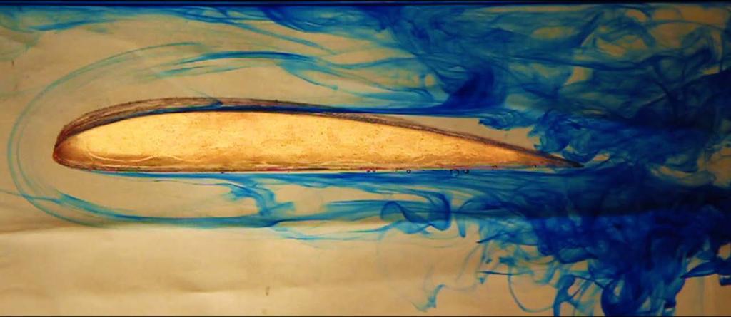
2 I. Background This project was the first team assignment of our Flow Visualization course at the University of Colorado at Boulder. The purpose of the project was to capture the fluid flow behavior of a Clark Y airfoil in a water flume. We attempted to visualize the shift of the separation point on the back of the wing as the angle of attack was increased. The angle of attack is the elevation from horizontal that the wing is tilted, and the separation point moves up from the back of the wing towards the front as this angle is increased. At the critical angle of attack, the wing is stalled and lift is decreased significantly (Gal-Or 1990). We also sought to capture the eloquence of the wave and vortex patterns present in the airfoil flow. This footage was captured with the collaborative effort of Shweta Maurya, Jeffrey Pilkington, and Dillon Thorse at the University of Colorado at Boulder on March 4, II. Flow Analysis The Clary Y airfoil was made from a source CAD file cut out of an acrylic sheet with a laser cutter (Nelson 2013). To capture the desired flow phenomena, the airfoil was placed in a water flume with a ventilated overshot weir downstream of the foil to create slow, more visible flow conditions. The airfoil was approximately five inches in chord length and one inch tall. Figure 1 shows the general flow pattern around the airfoil at a low angle of attack. The separation point is near the back tip of the wing when the angle of attack is approximately zero degrees, as seen in the first half of the video. In Figure 2, the angle of attack is increased to near the stalling point of the airfoil. The separation point shifts up the foil, inducing a turbulent boundary layer. When the critical angle of attack is achieved, the fluid flow no longer provides lift to the airfoil. Separation point Flow Airfoil QuickTime and a decompressor are needed to see this picture. Figure 1: Schematic of fluid flow over airfoil in water flume at a low angle of attack. Water is contained on three sides by the flume, with the surface of the water open to atmospheric pressure. 1
3 Separation point Flow QuickTime and a decompressor are needed to see this picture. Airfoil Turbulent region Figure 2: Schematic of fluid flow over airfoil in water flume at a high angle of attack. The separation point is high on the wing with a turbulent region formed near the back of the wing. The flow conditions in the experiment were controlled by the flume and pump. The flume channel was 3.31 inches (8.41 cm) wide and filled with water to a height of 5.7 inches (14.48 cm), yielding a rectangular cross sectional area of square inches ( cm 2 ). The pump circulated water through the flume at a flow rate of 2.17 L/s. Under these conditions, the Reynolds number for flow through an open channel can approximate the behavior of the fluid flow (Inamdar 2012): Re = vl υ (1) In Equation 1, v is the velocity of the flow through the flume, which can be approximately by dividing the flow rate, 2.17 L/s or 2,170 cm 3 /s, by the cross sectional area, cm 2. This yields a fluid velocity of 17.8 cm/s or m/s. The kinematic viscosity of the fluid is represented by υ, which is approximately E-6 m 2 /s for water at 20 C. The final quantity of the Reynolds number is the hydraulic radius of the channel, L, which is approximately by the following equation for open channel flow (Inamdar 2012): L = A WP = cm 2 = 2.66cm (2) 2(8.41cm) + 2(14.48cm) These values allow the Reynolds number to be calculated for the flow in front of the foil: Re = (0.178m /s)(0.0266m) ( m 2 /s) 4,716 2
4 The Reynolds number is a ratio of the kinematic to viscous forces within the fluid. This result indicates turbulent flow for the open channel, as Reynolds numbers greater than 2,000 are considered turbulent. However, this flow is not extremely turbulent, which is clear in the video, and still shows the transition of flow over the foil quite clearly due to the drastic difference in turbulence before and after the separation point. The fluid flow over the airfoil creates some very interesting fluid phenomena. In the first part of the video when the angle of attack is near zero, represented in Figure 1, a horseshoe vortex becomes apparent at the front of the wing as the dye travels over the foil. This phenomenon is the horseshoe-shaped dye shape visible at the front of the foil in the photo on the cover page of this report. The horseshoe vortex is formed by a constantly rotating bound vortex that travels with the foil, followed by two trailing vortices that form the sides of the horseshoe. The trailing vortices induce drag on the airfoil and are a component of the downwash (McCormick 1979). This phenomenon can also been seen in the context of tall buildings standing in the wind (Penwarden et al 1975). A second phenomenon is clearly visible in the second part of the video when the angle of attack is increased to near the stalling point, represented by Figure 2. The extreme turbulence created behind the separation point forms curling patterns known as Tollmien-Schlichting waves. These waves form as an instability at the boundary layer where the fluid transitions to turbulence (Baines et al 1996). Tollmien-Schlichting wave instabilities were illustrated very clearly in the second part of the video, where some of the waves became fully developed vortices downstream of the foil. With improved flow conditions and visualization techniques, both of these phenomena could be observed in even greater detail and clarity. III. Visualization Technique The flow over the airfoil was primarily visualized with blue food dye. The dye was dropped into the flume in volumetric additions of approximately one cubic centimeter at a distance of approximately 0.5 m upstream from the foil. This allowed the dye to disperse vertically within the flume and flow over both the top and bottom of the foil. The water circulated through the flume was at approximately room temperature (20 C), and was diffused through a bed of marbles at the top of the flume to reduce turbulence upstream of the airfoil. To light the flow, two 500 W tungsten bulbs were used to backlight a piece of white fabric used as a backdrop, which was attached to the side of the flume. This combination of visualization techniques provided nice contrast between the dye and the rest of the fluid, allowing the desired fluid phenomena to be captured clearly. 3
5 IV. Photographic Technique and Settings The field of view used to capture the footage was approximately 6 x 10 inches across, with the foil at a distance of approximately one meter from the lens of the camera. The footage was captured on an EF-S mm zoom lens at a focal length of 60 mm. A Canon EOS 60D DSLR camera was used to shoot the original footage that was 5184 x 3456 pixels in resolution. The video footage was captured at f/6.3 and 2500 ISO at 60 fps. Post processing was done in Adobe Aftereffects by providing fade in/out effects, cropping the frame, as well as making adjustments to the vibrance and contrast curves of the image. The final video is in 1080 x 720 resolution played back in a lossless video format. V. Conclusions The footage of the flow over the airfoil reveals how the separation point shifts up the wing as the angle of attack increases. After the foil reaches the critical angle of attack, the separation point is at the very front of the wing, which results in a dramatic decrease in lift and an increase in the amount of turbulence behind the wing. The airfoils also show fluid phenomena such as horseshoe vortices and Tollmien-Schlichting waves quite clearly. The contrast between the dye and the rest of the fluid visualizes the flow very well, which can be mostly attributed to the lighting method in combination with the dark color of the dye. To improve this experiment, one could adjust the flow parameters until the fluids Reynolds number is well within the laminar region, which would allow the transition to turbulence to be seen more clearly. Also, the video could be played back at a slower frame rate to more easily visualize the flow over the foil if desired. There is a lot to be learned about fluid flow over airfoils, including how fluid behavior changes with the use of different airfoils and fluid properties. Overall this project provided great insight into how an airfoil works, as well as what visualization techniques are the most effective. Baines, P. G., Majumdar, S. J., & Mitsudera, H. (1996).The mechanics of the tollmien-schlichting wave. Informally published manuscript, Department of Applied Mathematics and Theoretical Physics, University of Cambridge, Cambridge, United Kingdom. Retrieved from Gal-Or, Benjamin, "Vectored Propulsion, Supermaneuverability, and Robot Aircraft", Springer Verlag, 1990, ISBN 1990, ISBN , ISBN Inamdar, S. (2012). Open channel flow. Unpublished manuscript, Bioresources Engineering, University of Delaware, Newark, DE, Retrieved from McCormick, Barnes W., (1979), Aerodynamics, Aeronautics, and Flight Mechanics, John Wiley & Sons, Inc. New York ISBN Nelson, David. "Aerofoil (Clark Y)." GrabCAD. GrabCAD, 21 Feb Web. 3 Mar Penwarden, A.D., Wise, A.F.E., (1975) Wind environment around buildings, HMSO, London ISBN
Dillon Thorse Flow Visualization MCEN 4047 Team Poject 1 March 14th, 2013
 Dillon Thorse Flow Visualization MCEN 4047 Team Poject 1 March 14 th, 2013 1 Introduction I have always been entranced by flight. Recently I have been taking flying lessons, and I have been learning the
The effect of back spin on a table tennis ball moving in a viscous fluid.
 How can planes fly? The phenomenon of lift can be produced in an ideal (non-viscous) fluid by the addition of a free vortex (circulation) around a cylinder in a rectilinear flow stream. This is known as
Aerodynamic Analysis of Blended Winglet for Low Speed Aircraft
 , July 1-3, 2015, London, U.K. Aerodynamic Analysis of Blended Winglet for Low Speed Aircraft Pooja Pragati, Sudarsan Baskar Abstract This paper provides a practical design of a new concept of massive
AE Dept., KFUPM. Dr. Abdullah M. Al-Garni. Fuel Economy. Emissions Maximum Speed Acceleration Directional Stability Stability.
 Aerodynamics: Introduction Aerodynamics deals with the motion of objects in air. These objects can be airplanes, missiles or road vehicles. The Table below summarizes the aspects of vehicle performance
Low Speed Wind Tunnel Wing Performance
 Low Speed Wind Tunnel Wing Performance ARO 101L Introduction to Aeronautics Section 01 Group 13 20 November 2015 Aerospace Engineering Department California Polytechnic University, Pomona Team Leader:
Keywords: dynamic stall, free stream turbulence, pitching airfoil
 Applied Mechanics and Materials Vol. 225 (2012) pp 103-108 Online available since 2012/Nov/29 at www.scientific.net (2012) Trans Tech Publications, Switzerland doi:10.4028/www.scientific.net/amm.225.103
Applications of Bernoulli s principle. Principle states that areas with faster moving fluids will experience less pressure
 Applications of Bernoulli s principle Principle states that areas with faster moving fluids will experience less pressure Artery o When blood flows through narrower regions of arteries, the speed increases
Computational Analysis of Cavity Effect over Aircraft Wing
 World Engineering & Applied Sciences Journal 8 (): 104-110, 017 ISSN 079-04 IDOSI Publications, 017 DOI: 10.589/idosi.weasj.017.104.110 Computational Analysis of Cavity Effect over Aircraft Wing 1 P. Booma
Principles of glider flight
 Principles of glider flight [ Lecture 1: Lift, drag & glide performance ] Richard Lancaster Email: Richard@RJPLancaster.net Twitter: @RJPLancaster ASK-21 illustrations Copyright 1983 Alexander Schleicher
Experimental and Theoretical Investigation for the Improvement of the Aerodynamic Characteristic of NACA 0012 airfoil
 International Journal of Mining, Metallurgy & Mechanical Engineering (IJMMME) Volume 2, Issue 1 (214) ISSN 232 46 (Online) Experimental and Theoretical Investigation for the Improvement of the Aerodynamic
Lecture # 08: Boundary Layer Flows and Drag
 AerE 311L & AerE343L Lecture Notes Lecture # 8: Boundary Layer Flows and Drag Dr. Hui H Hu Department of Aerospace Engineering Iowa State University Ames, Iowa 511, U.S.A y AerE343L #4: Hot wire measurements
Reduction of Skin Friction Drag in Wings by Employing Riblets
 Reduction of Skin Friction Drag in Wings by Employing Riblets Kousik Kumaar. R 1 Assistant Professor Department of Aeronautical Engineering Nehru Institute of Engineering and Technology Coimbatore, India
Basic Fluid Mechanics
 Basic Fluid Mechanics Chapter 7B: Forces on Submerged Bodies 7/26/2018 C7B: Forces on Submerged Bodies 1 Forces on Submerged Bodies Lift and Drag are forces exerted on an immersed body by the surrounding
Preliminary Analysis of Drag Reduction for The Boeing
 Preliminary Analysis of Drag Reduction for The Boeing 747-400 By: Chuck Dixon, Chief Scientist, Vortex Control Technologies LLC 07. 31. 2012 Potential for Airflow Separation That Can Be Reduced By Vortex
No Description Direction Source 1. Thrust
 AERODYNAMICS FORCES 1. WORKING TOGETHER Actually Lift Force is not the only force working on the aircraft, during aircraft moving through the air. There are several aerodynamics forces working together
Lift for a Finite Wing. all real wings are finite in span (airfoils are considered as infinite in the span)
") Lift for a Finite Wing all real wings are finite in span (airfoils are considered as infinite in the span) The lift coefficient differs from that of an airfoil because there are strong vortices produced
Lift for a Finite Wing all real wings are finite in span (airfoils are considered as infinite in the span) The lift coefficient differs from that of an airfoil because there are strong vortices produced
8d. Aquatic & Aerial Locomotion. Zoology 430: Animal Physiology
 8d. Aquatic & Aerial Locomotion 1 Newton s Laws of Motion First Law of Motion The law of inertia: a body retains its state of rest or motion unless acted on by an external force. Second Law of Motion F
ROAD MAP... D-1: Aerodynamics of 3-D Wings D-2: Boundary Layer and Viscous Effects D-3: XFLR (Aerodynamics Analysis Tool)
") Unit D-1: Aerodynamics of 3-D Wings Page 1 of 5 AE301 Aerodynamics I UNIT D: Applied Aerodynamics ROAD MAP... D-1: Aerodynamics of 3-D Wings D-: Boundary Layer and Viscous Effects D-3: XFLR (Aerodynamics
Unit D-1: Aerodynamics of 3-D Wings Page 1 of 5 AE301 Aerodynamics I UNIT D: Applied Aerodynamics ROAD MAP... D-1: Aerodynamics of 3-D Wings D-: Boundary Layer and Viscous Effects D-3: XFLR (Aerodynamics
Parasite Drag. by David F. Rogers Copyright c 2005 David F. Rogers. All rights reserved.
 Parasite Drag by David F. Rogers http://www.nar-associates.com Copyright c 2005 David F. Rogers. All rights reserved. How many of you still have a Grimes rotating beacon on both the top and bottom of the
Measurement of Pressure. The aerofoil shape used in wing is to. Distribution and Lift for an Aerofoil. generate lift due to the difference
 Measurement of Pressure Distribution and Lift for an Aerofoil. Objective The objective of this experiment is to investigate the pressure distribution around the surface of aerofoil NACA 4415 and to determine
Induced Drag Reduction for Modern Aircraft without Increasing the Span of the Wing by Using Winglet
 International Journal of Mechanical & Mechatronics Engineering IJMME-IJENS Vol:10 No:03 49 Induced Drag Reduction for Modern Aircraft without Increasing the Span of the Wing by Using Winglet Mohammad Ilias
AERODYNAMICS I LECTURE 7 SELECTED TOPICS IN THE LOW-SPEED AERODYNAMICS
 LECTURE 7 SELECTED TOPICS IN THE LOW-SPEED AERODYNAMICS The sources of a graphical material used in this lecture are: [UA] D. McLean, Understanding Aerodynamics. Arguing from the Real Physics. Wiley, 2013.
Design & Analysis of Natural Laminar Flow Supercritical Aerofoil for Increasing L/D Ratio Using Gurney Flap
 Design & Analysis of Natural Laminar Flow Supercritical Aerofoil for Increasing L/D Ratio Using Gurney Flap U.Praveenkumar 1, E.T.Chullai 2 M.Tech Student, School of Aeronautical Science, Hindustan University,
A Numerical Simulation Comparing the Efficiencies of Tubercle Versus Straight Leading Edge Airfoils for a Darrieus Vertical Axis Wind Turbine
 A Numerical Simulation Comparing the Efficiencies of Tubercle Versus Straight Leading Edge Airfoils for a Darrieus Vertical Axis Wind Turbine By: Ross Neal Abstract: The efficiencies of sinusoidal and
Effect of Co-Flow Jet over an Airfoil: Numerical Approach
 Contemporary Engineering Sciences, Vol. 7, 2014, no. 17, 845-851 HIKARI Ltd, www.m-hikari.com http://dx.doi.org/10.12988/ces.2014.4655 Effect of Co-Flow Jet over an Airfoil: Numerical Approach Md. Riajun
Aerofoil Design for Man Powered Aircraft
 Man Powered Aircraft Group Aerofoil Design for Man Powered Aircraft By F. X. Wortmann Universitat Stuttgart From the Second Man Powered Aircraft Group Symposium Man Powered Flight The Way Ahead 7 th February
COMPUTER-AIDED DESIGN AND PERFORMANCE ANALYSIS OF HAWT BLADES
 5 th International Advanced Technologies Symposium (IATS 09), May 13-15, 2009, Karabuk, Turkey COMPUTER-AIDED DESIGN AND PERFORMANCE ANALYSIS OF HAWT BLADES Emrah KULUNK a, * and Nadir YILMAZ b a, * New
A COMPUTATIONAL STUDY ON THE DESIGN OF AIRFOILS FOR A FIXED WING MAV AND THE AERODYNAMIC CHARACTERISTIC OF THE VEHICLE
 28 TH INTERNATIONAL CONGRESS OF THE AERONAUTICAL SCIENCES A COMPUTATIONAL STUDY ON THE DESIGN OF AIRFOILS FOR A FIXED WING MAV AND THE AERODYNAMIC CHARACTERISTIC OF THE VEHICLE Jung-Hyun Kim*, Kyu-Hong
Relationship of roll and pitch oscillations in a fin flapping at transitional to high Reynolds numbers
 Supplementary Information: Relationship of roll and pitch oscillations in a fin flapping at transitional to high Reynolds numbers Authors: Promode R. Bandyopadhyay, David N. Beal, J. Dana Hrubes, and Arun
Welcome to Aerospace Engineering
 Welcome to Aerospace Engineering DESIGN-CENTERED INTRODUCTION TO AEROSPACE ENGINEERING Notes 4 Topics 1. Course Organization 2. Today's Dreams in Various Speed Ranges 3. Designing a Flight Vehicle: Route
Numerical Simulation And Aerodynamic Performance Comparison Between Seagull Aerofoil and NACA 4412 Aerofoil under Low-Reynolds 1
 Advances in Natural Science Vol. 3, No. 2, 2010, pp. 244-20 www.cscanada.net ISSN 171-7862 [PRINT] ISSN 171-7870 [ONLINE] www.cscanada.org *The 3rd International Conference of Bionic Engineering* Numerical
Available online at Procedia Engineering 200 (2010) (2009) In situ drag measurements of sports balls
 (2009) In situ drag measurements of sports balls") Available online at www.sciencedirect.com Procedia Engineering 200 (2010) (2009) 2437 2442 000 000 Procedia Engineering www.elsevier.com/locate/procedia 8 th Conference of the International Sports Engineering
Available online at www.sciencedirect.com Procedia Engineering 200 (2010) (2009) 2437 2442 000 000 Procedia Engineering www.elsevier.com/locate/procedia 8 th Conference of the International Sports Engineering
CFD Study of Solid Wind Tunnel Wall Effects on Wing Characteristics
 Indian Journal of Science and Technology, Vol 9(45), DOI :10.17485/ijst/2016/v9i45/104585, December 2016 ISSN (Print) : 0974-6846 ISSN (Online) : 0974-5645 CFD Study of Solid Wind Tunnel Wall Effects on
THEORY OF WINGS AND WIND TUNNEL TESTING OF A NACA 2415 AIRFOIL. By Mehrdad Ghods
 THEORY OF WINGS AND WIND TUNNEL TESTING OF A NACA 2415 AIRFOIL By Mehrdad Ghods Technical Communication for Engineers The University of British Columbia July 23, 2001 ABSTRACT Theory of Wings and Wind
HEFAT th International Conference on Heat Transfer, Fluid Mechanics and Thermodynamics July 2012 Malta
 HEFAT212 9 th International Conference on Heat Transfer, Fluid Mechanics and Thermodynamics 16 18 July 212 Malta AN EXPERIMENTAL STUDY OF SWEEP ANGLE EFFECTS ON THE TRANSITION POINT ON A 2D WING BY USING
SOARING AND GLIDING FLIGHT OF THE BLACK VULTURE
 [ 280 ] SOARING AND GLIDING FLIGHT OF THE BLACK VULTURE BY B. G. NEWMAN* Department of Engineering, University of Cambridge {Received 10 September 1957) INTRODUCTION In 1950 Raspet published an interesting
EXPERIMENTAL INVESTIGATION OF THE EFFECT OF VARIOUS WINGLET SHAPES ON THE TOTAL PRESSURE DISTRIBUTION BEHIND A WING
 24 TH INTERNATIONAL CONGRESS OF THE AERONAUTICAL SCIENCES EXPERIMENTAL INVESTIGATION OF THE EFFECT OF VARIOUS WINGLET SHAPES ON THE TOTAL PRESSURE DISTRIBUTION BEHIND A WING Mohammad Reza Soltani, Kaveh
Aerodynamic Performance Optimization Of Wind Turbine Blade By Using High Lifting Device
 Aerodynamic Performance Optimization Of Wind Turbine Blade By Using High Lifting Device Razeen Ridhwan, Mohamed Alshaleeh, Arunvinthan S Abstract: In the Aerodynamic performance of wind turbine blade by
AN EXPERIMENTAL STUDY OF THE EFFECTS OF SWEPT ANGLE ON THE BOUNDARY LAYER OF THE 2D WING
 AN EXPERIMENTAL STUDY OF THE EFFECTS OF SWEPT ANGLE ON THE BOUNDARY LAYER OF THE 2D WING A. Davari *, M.R. Soltani, A.Tabrizian, M.Masdari * Assistant Professor, Department of mechanics and Aerospace Engineering,
STUDY OF MICROBUBBLES FOR SKIN-FRICTION DRAG REDUCTION. *
 STUDY OF MICROBUBBLES FOR SKIN-FRICTION DRAG REDUCTION Yan Yao 1 *, Jin-ling Luo 1,Kun Zhu 1, Hai-bo He 1, Rui Wu 2, Shi-jie Qin 3 1 Beijing Electromechanic Engineering Institute, Beijing, 100074, China
2-D Computational Analysis of a Vertical Axis Wind Turbine Airfoil
 2-D Computational Analysis of a Vertical Axis Wind Turbine Airfoil Akshay Basavaraj1 Student, Department of Aerospace Engineering, Amrita School of Engineering, Coimbatore 641 112, India1 Abstract: This
Jet Propulsion. Lecture-17. Ujjwal K Saha, Ph. D. Department of Mechanical Engineering Indian Institute of Technology Guwahati
 Lecture-17 Prepared under QIP-CD Cell Project Jet Propulsion Ujjwal K Saha, Ph. D. Department of Mechanical Engineering Indian Institute of Technology Guwahati 1 Lift: is used to support the weight of
Theory of Flight Stalls. References: FTGU pages 18, 35-38
 Theory of Flight 6.07 Stalls References: FTGU pages 18, 35-38 Review 1. What are the two main types of drag? 2. Is it possible to eliminate induced drag? Why or why not? 3. What is one way to increase
Lesson: Airspeed Control
 11/20/2018 Airspeed Control Page 1 Lesson: Airspeed Control Objectives: o Knowledge o An understanding of the aerodynamics related to airspeed control o Skill o The ability to establish and maintain a
Kinematics of Vorticity
 Kinematics of Vorticity Vorticity Ω Ω= V 2 circumferentially averaged angular velocity of the fluid particles Sum of rotation rates of perpendicular fluid lines Non-zero vorticity doesn t imply spin.ω=0.
STUDY OF VARIOUS NACA SERIES AEROFOIL SECTIONS AND WING CONTOUR GENERATION USING CATIA V5
 STUDY OF VARIOUS NACA SERIES AEROFOIL SECTIONS AND WING CONTOUR GENERATION USING CATIA V5 Pawan Kumar Department of Aeronautical Engineering, Desh Bhagat University, Punjab, India ABSTRACT Aerofoil is
Lab 4: Pressure Gradients over a Wing
 2009 Lab 4: Pressure Gradients over a Wing Innovative Scientific Solutions Inc. 2766 Indian Ripple Road Dayton, OH 45440 (937)-429-4980 Lab 4: Pressure Gradients over a Wing Introduction: Like the previous
Aerodynamic Terms. Angle of attack is the angle between the relative wind and the wing chord line. [Figure 2-2] Leading edge. Upper camber.
![Aerodynamic Terms. Angle of attack is the angle between the relative wind and the wing chord line. [Figure 2-2] Leading edge. Upper camber.](/thumbs/82/86661300.jpg "Aerodynamic Terms. Angle of attack is the angle between the relative wind and the wing chord line. [Figure 2-2] Leading edge. Upper camber.") Chapters 2 and 3 of the Pilot s Handbook of Aeronautical Knowledge (FAA-H-8083-25) apply to powered parachutes and are a prerequisite to reading this book. This chapter will focus on the aerodynamic fundamentals
Chapters 2 and 3 of the Pilot s Handbook of Aeronautical Knowledge (FAA-H-8083-25) apply to powered parachutes and are a prerequisite to reading this book. This chapter will focus on the aerodynamic fundamentals
CFD AND EXPERIMENTAL STUDY OF AERODYNAMIC DEGRADATION OF ICED AIRFOILS
 Colloquium FLUID DYNAMICS 2008 Institute of Thermomechanics AS CR, v.v.i., Prague, October 22-24, 2008 p.1 CFD AND EXPERIMENTAL STUDY OF AERODYNAMIC DEGRADATION OF ICED AIRFOILS Vladimír Horák 1, Dalibor
CIRCULATION PRODUCTION AND SHEDDING FROM VERTICAL AXIS WIND TURBINE BLADES UNDERGOING DYNAMIC STALL
 June 3 - July 3, 5 Melbourne, Australia 9 7D-3 CIRCULATION PRODUCTION AND SHEDDING FROM VERTICAL AXIS WIND TURBINE BLADES UNDERGOING DYNAMIC STALL Abel-John Buchner,,, Julio Soria,3, Alexander J. Smits,
ScienceDirect. Investigation of the aerodynamic characteristics of an aerofoil shaped fuselage UAV model
 Available online at www.sciencedirect.com ScienceDirect Procedia Engineering 90 (2014 ) 225 231 10th International Conference on Mechanical Engineering, ICME 2013 Investigation of the aerodynamic characteristics
What happens to a fluid (water or air) when it moves from entering a wide opening to entering a narrow opening?
 when it moves from entering a wide opening to entering a narrow opening?") What happens to a fluid (water or air) when it moves from entering a wide opening to entering a narrow opening? The water (or air) speeds up. Since the same amount of water/air has to travel through a
What happens to a fluid (water or air) when it moves from entering a wide opening to entering a narrow opening? The water (or air) speeds up. Since the same amount of water/air has to travel through a
The subsonic compressibility effect is added by replacing. with
 Swept Wings The main function of a swept wing is to reduce wave drag at transonic and supersonic speeds. Consider a straight wing and a swept wing in a flow with a free-stream velocity V. Assume that the
Quantification of the Effects of Turbulence in Wind on the Flutter Stability of Suspension Bridges
 Quantification of the Effects of Turbulence in Wind on the Flutter Stability of Suspension Bridges T. Abbas 1 and G. Morgenthal 2 1 PhD candidate, Graduate College 1462, Department of Civil Engineering,
AF100. Subsonic Wind Tunnel AERODYNAMICS. Open-circuit subsonic wind tunnel for a wide range of investigations into aerodynamics
 Open-circuit subsonic wind tunnel for a wide range of investigations into aerodynamics Page 1 of 4 Works with Computer, chair and work table shown for photographic purposes only (not included) Screenshot
AERODYNAMIC CHARACTERISTICS OF NACA 0012 AIRFOIL SECTION AT DIFFERENT ANGLES OF ATTACK
 AERODYNAMIC CHARACTERISTICS OF NACA 0012 AIRFOIL SECTION AT DIFFERENT ANGLES OF ATTACK SUPREETH NARASIMHAMURTHY GRADUATE STUDENT 1327291 Table of Contents 1) Introduction...1 2) Methodology.3 3) Results...5
Air Craft Winglet Design and Performance: Cant Angle Effect
 Journal of Robotics and Mechanical Engineering Research Air Craft Winglet Design and Performance: Cant Angle Effect Eslam Said Abdelghany 1, Essam E Khalil 2*, Osama E Abdellatif 3 and Gamal elhariry 4
Avai 193 Fall 2016 Laboratory Greensheet
 Avai 193 Fall 2016 Laboratory Greensheet Lab Report 1 Title: Instrumentation Test Technique Research Process: Break into groups of 4 people. These groups will be the same for all of the experiments performed
Investigation on 3-D Wing of commercial Aeroplane with Aerofoil NACA 2415 Using CFD Fluent
 Investigation on 3-D of commercial Aeroplane with Aerofoil NACA 2415 Using CFD Fluent Rohit Jain 1, Mr. Sandeep Jain 2, Mr. Lokesh Bajpai 3 1PG Student, 2 Associate Professor, 3 Professor & Head 1 2 3
ANALYSIS OF AERODYNAMIC CHARACTERISTICS OF A SUPERCRITICAL AIRFOIL FOR LOW SPEED AIRCRAFT
 ANALYSIS OF AERODYNAMIC CHARACTERISTICS OF A SUPERCRITICAL AIRFOIL FOR LOW SPEED AIRCRAFT P.Sethunathan 1, M.Niventhran 2, V.Siva 2, R.Sadhan Kumar 2 1 Asst.Professor, Department of Aeronautical Engineering,
Computational Analysis of the S Airfoil Aerodynamic Performance
 Computational Analysis of the 245-3S Airfoil Aerodynamic Performance Luis Velazquez-Araque and Jiří Nožička 2 Department of Mechanical Engineering National University of Táchira, San Cristóbal 5, Venezuela
C-1: Aerodynamics of Airfoils 1 C-2: Aerodynamics of Airfoils 2 C-3: Panel Methods C-4: Thin Airfoil Theory
 ROAD MAP... AE301 Aerodynamics I UNIT C: 2-D Airfoils C-1: Aerodynamics of Airfoils 1 C-2: Aerodynamics of Airfoils 2 C-3: Panel Methods C-4: Thin Airfoil Theory AE301 Aerodynamics I : List of Subjects
CFD ANALYSIS OF FLOW AROUND AEROFOIL FOR DIFFERENT ANGLE OF ATTACKS
 www.mechieprojects.com CFD ANALYSIS OF FLOW AROUND AEROFOIL FOR DIFFERENT ANGLE OF ATTACKS PRESENTATION OUTLINE AIM INTRODUCTION LITERATURE SURVEY CFD ANALYSIS OF AEROFOIL RESULTS CONCLUSIONS www.mechieprojects.com
SEMI-SPAN TESTING IN WIND TUNNELS
 25 TH INTERNATIONAL CONGRESS OF THE AERONAUTICAL SCIENCES SEMI-SPAN TESTING IN WIND TUNNELS S. Eder, K. Hufnagel, C. Tropea Chair of Fluid Mechanics and Aerodynamics, Darmstadt University of Technology
AN EXPERIMENTAL INVESTIGATION OF SPILLING BREAKERS
 AN EXPERIMENTAL INVESTIGATION OF SPILLING BREAKERS Prof. James H. Duncan Department of Mechanical Engineering University of Maryland College Park, Maryland 20742-3035 phone: (301) 405-5260, fax: (301)
A comparison of NACA 0012 and NACA 0021 self-noise at low Reynolds number
 A comparison of NACA 12 and NACA 21 self-noise at low Reynolds number A. Laratro, M. Arjomandi, B. Cazzolato, R. Kelso Abstract The self-noise of NACA 12 and NACA 21 airfoils are recorded at a Reynolds
Incompressible Potential Flow. Panel Methods (3)
") Incompressible Potential Flow Panel Methods (3) Outline Some Potential Theory Derivation of the Integral Equation for the Potential Classic Panel Method Program PANEL Subsonic Airfoil Aerodynamics Issues
Incompressible Potential Flow Panel Methods (3) Outline Some Potential Theory Derivation of the Integral Equation for the Potential Classic Panel Method Program PANEL Subsonic Airfoil Aerodynamics Issues
Numerical Investigation of Multi Airfoil Effect on Performance Increase of Wind Turbine
 International Journal of Engineering & Applied Sciences (IJEAS) International Journal of Engineering Applied Sciences (IJEAS) Vol.9, Issue 3 (2017) 75-86 Vol.x, Issue x(201x)x-xx http://dx.doi.org/10.24107/ijeas.332075
DEFINITIONS. Aerofoil
 Aerofoil DEFINITIONS An aerofoil is a device designed to produce more lift (or thrust) than drag when air flows over it. Angle of Attack This is the angle between the chord line of the aerofoil and the
THREE DIMENSIONAL STRUCTURES OF FLOW BEHIND A
 The Seventh Asia-Pacific Conference on Wind Engineering, November 8-12, 29, Taipei, Taiwan THREE DIMENSIONAL STRUCTURES OF FLOW BEHIND A SQUARE PRISM Hiromasa Kawai 1, Yasuo Okuda 2 and Masamiki Ohashi
Incompressible Flow over Airfoils
 Road map for Chap. 4 Incompressible Flow over Airfoils Aerodynamics 2015 fall - 1 - < 4.1 Introduction > Incompressible Flow over Airfoils Incompressible flow over airfoils Prandtl (20C 초 ) Airfoil (2D)
Improved Aerodynamic Characteristics of Aerofoil Shaped Fuselage than that of the Conventional Cylindrical Shaped Fuselage
 International Journal of Scientific & Engineering Research Volume 4, Issue 1, January-213 1 Improved Aerodynamic Characteristics of Aerofoil Shaped Fuselage than that of the Conventional Cylindrical Shaped
Application of vortex generators in ship propulsion system design M. Oledal
 Application of vortex generators in ship propulsion system design M. Oledal TecAWogy, TV- 74JO E-mail: marcus.oledal@termo.unit.no Abstract An experimental study of vortex generators for hydraulic applications
Aerodynamic characteristics around the stalling angle of the discus using a PIV
 10TH INTERNATIONAL SYMPOSIUM ON PARTICLE IMAGE VELOCIMETRY PIV13 Delft, The Netherlands, July 1-3, 2013 Aerodynamic characteristics around the stalling angle of the discus using a PIV Kazuya Seo 1 1 Department
Aerodynamic behavior of a discus
 Available online at www.sciencedirect.com Procedia Engineering 34 (2012 ) 92 97 9 th Conference of the International Sports Engineering Association (ISEA) Aerodynamic behavior of a discus Kazuya Seo a*,
The Effect of Gurney Flap Height on Vortex Shedding Modes Behind Symmetric Airfoils
 The Effect of Gurney Flap Height on Vortex Shedding Modes Behind Symmetric Airfoils Daniel R. Troolin 1, Ellen K. Longmire 2, Wing T. Lai 3 1: TSI Incorporated, St. Paul, USA, dan.troolin@tsi.com 2: University
Aerodynamically Efficient Wind Turbine Blade S Arunvinthan 1, Niladri Shekhar Das 2, E Giriprasad 3 (Avionics, AISST- Amity University, India)
") International Journal of Engineering Science Invention ISSN (Online): 2319 6734, ISSN (Print): 2319 6726 Volume 3 Issue 4ǁ April 2014ǁ PP.49-54 Aerodynamically Efficient Wind Turbine Blade S Arunvinthan
International Journal of Engineering Science Invention ISSN (Online): 2319 6734, ISSN (Print): 2319 6726 Volume 3 Issue 4ǁ April 2014ǁ PP.49-54 Aerodynamically Efficient Wind Turbine Blade S Arunvinthan
EXPERIMENTAL ANALYSIS OF FLOW OVER SYMMETRICAL AEROFOIL Mayank Pawar 1, Zankhan Sonara 2 1,2
 EXPERIMENTAL ANALYSIS OF FLOW OVER SYMMETRICAL AEROFOIL Mayank Pawar 1, Zankhan Sonara 2 1,2 Assistant Professor,Chandubhai S. Patel Institute of Technology, CHARUSAT, Changa, Gujarat, India Abstract The
Unsteady airfoil experiments
 Unsteady airfoil experiments M.F. Platzer & K.D. Jones AeroHydro Research & Technology Associates, Pebble Beach, CA, USA. Abstract This paper describes experiments that elucidate the dynamic stall phenomenon
CHAPTER-1 INTRODUCTION
 CHAPTER-1 INTRODUCTION 1 1.1 Introduction This investigation documents the aerodynamic characteristics of four profiles, as cylinder, sphere, symmetrical aerofoil (NACA 0015) and cambered aerofoil (NACA
Influence of rounding corners on unsteady flow and heat transfer around a square cylinder
 Influence of rounding corners on unsteady flow and heat transfer around a square cylinder S. K. Singh Deptt. of Mech. Engg., M. B. M. Engg. College / J. N. V. University, Jodhpur, Rajasthan, India Abstract
Experimental investigation on the aft-element flapping of a two-element airfoil at high attack angle
 Experimental investigation on the aft-element flapping of a two-element airfoil at high attack angle Tan Guang-kun *, Shen Gong-xin, Su Wen-han Beijing University of Aeronautics and Astronautics (BUAA),
Vortical Patterns in the Wake of an Oscillating Airfoil
 1200 AIAA JOURNAL VOL. 27, NO. 9, SEPTEMBER 1989 Vortical Patterns in the Wake of an Oscillating Airfoil Manoochehr M. Koochesfahani* California Institute of Technology, Pasadena, California The vortical
Wing-Body Combinations
 Wing-Body Combinations even a pencil at an angle of attack will generate lift, albeit small. Hence, lift is produced by the fuselage of an airplane as well as the wing. The mating of a wing with a fuselage
PRE-TEST Module 2 The Principles of Flight Units /60 points
 PRE-TEST Module 2 The Principles of Flight Units 1-2-3.../60 points 1 Answer the following questions. (20 p.) moving the plane (4) upward / forward. Opposed to that is 1. What are the names of the four
Flow Field Phenomena about Lift and Downforce Generating Cambered Aerofoils in Ground Effect
 16 th Australasian Fluid Mechanics Conference Crown Plaza, Gold Coast, Australia 2-7 December 2007 Flow Field Phenomena about Lift and Downforce Generating Cambered Aerofoils in Ground Effect J.W. Vogt,
EXPERIMENTAL ANALYSIS OF THE CONFLUENT BOUNDARY LAYER BETWEEN A FLAP AND A MAIN ELEMENT WITH SAW-TOOTHED TRAILING EDGE
 24 TH INTERNATIONAL CONGRESS OF THE AERONAUTICAL SCIENCES EXPERIMENTAL ANALYSIS OF THE CONFLUENT BOUNDARY LAYER BETWEEN A FLAP AND A MAIN ELEMENT WITH SAW-TOOTHED TRAILING EDGE Lemes, Rodrigo Cristian,
AERODYNAMIC CHARACTERISTICS OF SPIN PHENOMENON FOR DELTA WING
 ICAS 2002 CONGRESS AERODYNAMIC CHARACTERISTICS OF SPIN PHENOMENON FOR DELTA WING Yoshiaki NAKAMURA (nakamura@nuae.nagoya-u.ac.jp) Takafumi YAMADA (yamada@nuae.nagoya-u.ac.jp) Department of Aerospace Engineering,
EXPERIMENTAL STUDY ON SNOW BEHAVIOR AROUND FENCES INSTALLED ALONG ELEVATED HIGHWAY
 ISTP-16, 25, PRAGUE 16 TH INTERNATIONAL SYMPOSIUM ON TRANSPORT PHENOMENA EXPERIMENTAL STUDY ON SNOW BEHAVIOR AROUND FENCES INSTALLED ALONG ELEVATED HIGHWAY Akinori Nakata*, Haruo Soeda*, Junji Onishi*,
Wind tunnel effects on wingtip vortices
 48th AIAA Aerospace Sciences Meeting Including the New Horizons Forum and Aerospace Exposition 4-7 January 2010, Orlando, Florida AIAA 2010-325 Wind tunnel effects on wingtip vortices Xin Huang 1, Hirofumi
A child places a car of mass 95 g on the track. She adjusts the controller to a power of 4.2 W so the car accelerates from rest for 0.40 s.
 1 The picture shows a track for racing toy electric cars. A guide pin fits in a groove in the track to keep the car on the track. A small electric motor in the car is controlled, with a hand-controller,
Preliminary design of a high-altitude kite. A flexible membrane kite section at various wind speeds
 Preliminary design of a high-altitude kite A flexible membrane kite section at various wind speeds This is the third paper in a series that began with one titled A flexible membrane kite section at high
It should be noted that the symmetrical airfoil at zero lift has no pitching moment about the aerodynamic center because the upper and
 NAVWEPS -81-8 and high power, the dynamic pressure in the shaded area can be much greater than the free stream and this causes considerably greater lift than at zero thrust. At high power conditions the
Bioreactor System ERT 314. Sidang /2011
 Bioreactor System ERT 314 Sidang 1 2010/2011 Chapter 2:Types of Bioreactors Week 4 Flow Patterns in Agitated Tanks The flow pattern in an agitated tank depends on the impeller design, the properties of
DEPARTMENT OF THE NAVY NAVAL UNDERSEA WARFARE CENTER DIVISION NEWPORT
 DEPARTMENT OF THE NAVY NAVAL UNDERSEA WARFARE CENTER DIVISION NEWPORT gsop P OFFICE OF COUNSEL (PATENTS) 14 1176 HOWELL STREET Q w BUILDING 112T, CODE OOOC NEWPORT, RHODE ISLAND 02841-1708 PHONE: 401 832-4736
Aerodynamic Basics Larry Bogan - Jan 2002 version MECHANICS
 Aerodynamic Basics Larry Bogan - Jan 2002 version MECHANICS Vectors Force, displacement, acceleration, and velocity Inertia and Velocity Inertia is a property of mass. (When there is no force on an object,
Figure 1. Curtis 1911 model D type IV pusher
 This material can be found in more detail in Understanding Flight 1 st and 2 nd editions by David Anderson and Scott Eberhardt, McGraw-Hill, 2001, and 2009 A Physical Description of Flight; Revisited David
BUILD AND TEST A WIND TUNNEL
 LAUNCHING INTO AVIATION 9 2018 Aircraft Owners and Pilots Association. All Rights Reserved. UNIT 2 SECTION D LESSON 2 PRESENTATION BUILD AND TEST A WIND TUNNEL LEARNING OBJECTIVES By the end of this lesson,
High Swept-back Delta Wing Flow
 Advanced Materials Research Submitted: 2014-06-25 ISSN: 1662-8985, Vol. 1016, pp 377-382 Accepted: 2014-06-25 doi:10.4028/www.scientific.net/amr.1016.377 Online: 2014-08-28 2014 Trans Tech Publications,
Aerofoils, Lift, Drag and Circulation
 Aerofoils, Lift, Drag and Circulation 4.0 Introduction In Section 3.3 we saw that the assumption that blade elements behave as aerofoils allows the analysis of wind turbines in terms of the lift and drag