Relationship of roll and pitch oscillations in a fin flapping at transitional to high Reynolds numbers
|
|
|
- Bartholomew Washington
- 5 years ago
- Views:
Transcription

1 Supplementary Information: Relationship of roll and pitch oscillations in a fin flapping at transitional to high Reynolds numbers Authors: Promode R. Bandyopadhyay, David N. Beal, J. Dana Hrubes, and Arun Mangalam This supplementary information comprises Part 1: Data and Part 2: Video. Part 1: Data 1.1 Nomenclature: The fin profiles were measured at different spans to confirm that the fin twisted without the production of any camber, as shown in figure SI1. Therefore, the results are free of cambering effects. t Figure SI1. Schematic of camberless twisting of fin. 1
2 1.2 Dye visualization: Dot dye: Sigma Aldrich Brilliant Green Dye B-6756 (research grade, not food grade) was used in the early work with non-twisting fins (see figure 5 in paper). Dissolvable dye buttons were created, following inspiration from Ellington. On the stove a sucrose solution was created and dye was added until a smooth consistency with a deep color was achieved. This thick paste was immediately applied as dots or buttons at various locations on the fin and allowed to dry overnight. During flow visualization tests, the dye buttons dissolved in the surrounding water and created visualization trails. Dye injection: In the later visualizations (figure 9 to 11) comparing the leading-edge vortex in twisting and non-twisting fins during hovering, liquid dye was plumbed through holes on the fin surface. See figure SI2. Figure SI2a shows the dimensions of the flexible fin and the dye port layout. Figure SI2b shows the dye plumbing. Figure SI2c shows a photograph of the dye injection apparatus. Red and blue dyes were injected slightly under pressure, each on opposing sides of the fin near the leading edge and through five surface-flush ports along the span. The dyes used were Hilton- Davis FD&C Red #40 certified food color and Sigma Aldrich Brilliant Green Dye B A minimum amount was dissolved in water to produce a vivid visualization image. Whole milk of less than 10% fat content was added to inhibit diffusion of the dye mixture in water. We had a spray unit with a hand pump that had a capacity of approximately 1 gallon. It is the type of spray bottle used in the yard to spray insecticide. That output was used to simultaneously pressurize two separate bottles that contained the two different color dyes. Each output of the two dye bottles ran through a controlling needle valve which then fed to the foil. A few test runs were made to find the optimum setting for each needle valve resulting in the desired dye flow rate. For each run, the pressure was pumped to a predetermined value while monitoring a pressure gauge and the duration of the run was short to keep the feed pressure and flow rate nearly constant. 2
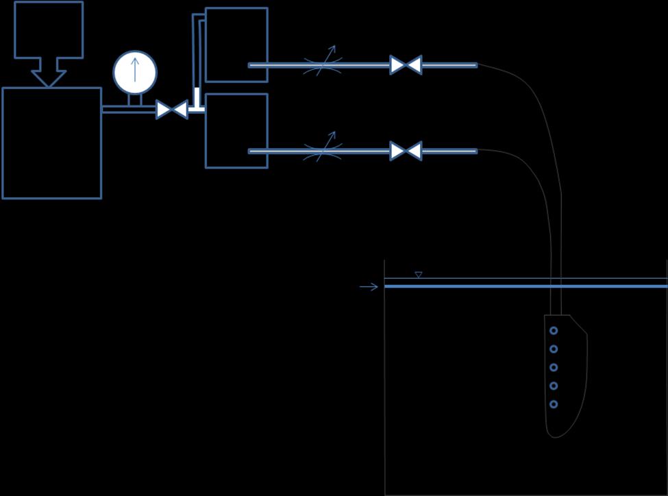
3 (a) (b) 3

4 (c) Figure SI2. Layout of the injection holes on the flexible fin (a); the dimensions are in cm. Dye injection plumbing: (b) schematic; (c) photograph. Camera: We used two Sony Handy-Cam Camcorders and using manual focus control, but we used automatic exposure control so the f-stop is unknown. The lens focal length was unknown, because we just used the zoom lens to frame the desired image. The frame rate was standard 30 frames/second and the resolution was standard 640 by 480 pixels. 4

5 1.3 Wall-shear stress gauge array layout: Figure SI3a shows a photograph of the rigid fin populated with the surface hot-film array. Figure SI3b shows the layout of the array. Note that the array is closely spaced near the leading edge. (a) 5
 Photograph of the fin (NACA0012-34 section with slightly thickened trailing edge). The chord (10.16 cm) runs vertically, and the span (20.")
6 (b) Figure SI3. Layout of the staggered surface hot-film array on the fin. (a) Photograph of the fin (NACA section with slightly thickened trailing edge). The chord (10.16 cm) runs vertically, and the span (20.32 cm) runs horizontally. (b) Chordwise and spanwise stagger of the 6

7 film locations. The hot-film gauge spacing is narrower near the leading edge. The gauges are denoted by the numbers in the red circles. They are sequenced left to right above the broken line marked leading edge and right to left below that. There are inactive gauges in rows 5 10, counting from the top. Static Calibration: Figure SI4 shows the time traces of the ho-film outputs; the vertical axis contains the sensor numbers (S-01, ). Figure SI4 shows that the data acquisition and signal analysis are capturing the phase reversal at the stagnation point at pitch amplitude of 0. The point of stagnation lies between sensors 5 and 12 (see figure SI3 above), whose strip-chart voltage recordings are shown in the second and third rows, respectively. 7
8 Figure SI4. Phase reversal verification between sensors 5 (S-05) and 12 (S-12) (second and third strip-charts from top); pitch amplitude is zero degrees. Figure SI5 shows the results of data analysis for obtaining the static relationship between the location of the stagnation point and lift. Obtaining all the stagnation point locations over the entire range of pitch angles (-20 to 20 in 2 increments) produces figure SI5 (a). The stagnation point location in figure SI5 (a) is essentially a range between two sensor locations determined through the phase reversal, as shown in figure SI4. The curve-fit in lift is a fifthorder polynomial fit. (a) Stagnation point location. 8
9 (b) Distribution of lift coefficient. 9
10 (c) Comparison of measured and calculated lift. The equation in section 2.2 of the paper (equation 13 in the paper) is a fit to the data as shown above. Figure SI5. Static relationship between the location of the stagnation point and lift. 10
11 1.4. Relationship between St, pitch amplitude, angle of attack at the average span, thrust and efficiency: Measurements of efficiency and thrust are shown in Figures SI6 to SI9. In Figures SI6 and SI7, the axes are Strouhal number versus pitch amplitude, and in figures SI8 and SI9, the axes are Strouhal number versus angle of attack at the average radial location of the fin span. Figures SI6 and SI8 show efficiency and figures SI7 and SI9 show thrust. In figure SI6, note that efficiency reaches the maximum value (> 0.57) in a narrow region of Strouhal number and pitch amplitude (shown by the solid line). Figure SI7 shows the direction where thrust drops. Figure SI8 marks the region where efficiency is > Figure SI9 marks the region where efficiency is maximum (> 0.57). Figures SI8 and 9 also show the region where thrust is a maximum, but efficiency is low. 11
12 Figure SI6. There are blue regions at both high and low St boundaries. So, there is a ridge in between. This figure shows that for high eta (deep red) you get a steep ridge. We are seeing how resonance is optimizing the flow. Untwisted fin. The blue line shows where efficiency is a maximum. All data are for tow. 12
13 Figure SI7. Figure shows when thrust drops. Untwisted fin. All data are for tow. 13
.")
14 Figure SI8. Efficiency drops rapidly at the St boundaries of the marked high η region. Untwisted fin. Note that St and η during hovering are based on the induced velocity which was modeled assuming disk flow (Wakeling & Ellington 1997). The hovering data follow the trend of the tow data. 14
15 Figure SI9. Figure shows the direction of drop in thrust in the favored St region. Very high thrust is produced at high angles of attack, but that is not an efficient region. Untwisted fin. Note that St and CT,wing (=CX,wingin the manuscript) during hovering are based on the induced velocity which are modeled assuming disk flow (Wakeling & Ellington 1997). The hovering data follow the trend of the tow data. 15
16 1.5 Quasi-steady modeling Figures SI10 and 11 show detailed results of the modeling. The former shows the variations of forces and power when twist amplitudes are 0 (a), (b) 10, (c) 20, and (d) 40. The latter shows similar information but at different spanwise panels. (a) (b) 16

17 (c) (d) Figure SI10. Comparison of measurements and quasi-steady model at twist angles θ t0 of (a) 0, (b) 10, (c) 20, and (d) 40. The angles of attack are computed values. They are at panels along the span with color changing from blue at the root to red at the fin tip. Fin kinematics: 0 = 30, R avg = 40, f = 1.00 Hz, U = 1.00 m/s, St = (a) (b) 17
18 (c) (d) Figure SI11. Variation of the angle of attack, force coefficients, and power with twist, in panels along the span estimated using the cross-flow vortex model. Color: Root (blue), tip (red). Fin kinematics are: 0 = 30, R = 40, f = 1.00 Hz, U = 1.00 m/s, St = avg Twist angles θ t0 are: (a) 0, (b) 10, (c) 20, and (d)
19 Part 2: Video Video SI1: Disturbance rejection by flapping fin driven by van der Pol oscillator: File Names: (a) Fin Oscillator Roll vs Pitch Bandyopadhyay; (b) van der Pol Disturbance Rejection xload yload traces Bandyopadhyay Size and Format: (a) 326 KB Windows Media Video File (b) 2,467 KB with Audio Windows Media Video File The fin is given a square pulse of external disturbance. Reference: Bandyopadhyay et al. 2008b IEEE Jou. Oceanic Engrg. Video SI2: Leading-Edge Vortex Dye Visualization in Rigid and Twisting Fins During Hovering: File Name: LEV-Final.mov Size: 8,638 KB Format: Quick Time Movie 19
EFFECT OF CORNER CUTOFFS ON FLOW CHARACTERISTICS AROUND A SQUARE CYLINDER
 EFFECT OF CORNER CUTOFFS ON FLOW CHARACTERISTICS AROUND A SQUARE CYLINDER Yoichi Yamagishi 1, Shigeo Kimura 1, Makoto Oki 2 and Chisa Hatayama 3 ABSTRACT It is known that for a square cylinder subjected
Group Project Flume Airfoil Flow
 Group Project Flume Airfoil Flow Alexander B. Meyer Mechanical Engineering I. Background This project was the first team assignment of our Flow Visualization course at the University of Colorado at Boulder.
Aerodynamic Terms. Angle of attack is the angle between the relative wind and the wing chord line. [Figure 2-2] Leading edge. Upper camber.
![Aerodynamic Terms. Angle of attack is the angle between the relative wind and the wing chord line. [Figure 2-2] Leading edge. Upper camber.](/thumbs/82/86661300.jpg "Aerodynamic Terms. Angle of attack is the angle between the relative wind and the wing chord line. [Figure 2-2] Leading edge. Upper camber.") Chapters 2 and 3 of the Pilot s Handbook of Aeronautical Knowledge (FAA-H-8083-25) apply to powered parachutes and are a prerequisite to reading this book. This chapter will focus on the aerodynamic fundamentals
Chapters 2 and 3 of the Pilot s Handbook of Aeronautical Knowledge (FAA-H-8083-25) apply to powered parachutes and are a prerequisite to reading this book. This chapter will focus on the aerodynamic fundamentals
PRESSURE DISTRIBUTION OF SMALL WIND TURBINE BLADE WITH WINGLETS ON ROTATING CONDITION USING WIND TUNNEL
 International Journal of Mechanical and Production Engineering Research and Development (IJMPERD ) ISSN 2249-6890 Vol.2, Issue 2 June 2012 1-10 TJPRC Pvt. Ltd., PRESSURE DISTRIBUTION OF SMALL WIND TURBINE
DEFINITIONS. Aerofoil
 Aerofoil DEFINITIONS An aerofoil is a device designed to produce more lift (or thrust) than drag when air flows over it. Angle of Attack This is the angle between the chord line of the aerofoil and the
C-1: Aerodynamics of Airfoils 1 C-2: Aerodynamics of Airfoils 2 C-3: Panel Methods C-4: Thin Airfoil Theory
 ROAD MAP... AE301 Aerodynamics I UNIT C: 2-D Airfoils C-1: Aerodynamics of Airfoils 1 C-2: Aerodynamics of Airfoils 2 C-3: Panel Methods C-4: Thin Airfoil Theory AE301 Aerodynamics I : List of Subjects
Signature redacted Signature of Author:... Department of Mechanical Engineering
 Review of Flapping Foil Actuation and Testing of Impulsive Motions for Large, Transient Lift and Thrust Profiles by Miranda Kotidis Submitted to the Department of Mechanical Engineering in Partial Fulfillment
COMPUTER-AIDED DESIGN AND PERFORMANCE ANALYSIS OF HAWT BLADES
 5 th International Advanced Technologies Symposium (IATS 09), May 13-15, 2009, Karabuk, Turkey COMPUTER-AIDED DESIGN AND PERFORMANCE ANALYSIS OF HAWT BLADES Emrah KULUNK a, * and Nadir YILMAZ b a, * New
Results and Discussion for Steady Measurements
 Chapter 5 Results and Discussion for Steady Measurements 5.1 Steady Skin-Friction Measurements 5.1.1 Data Acquisition and Reduction A Labview software program was developed for the acquisition of the steady
Low Speed Wind Tunnel Wing Performance
 Low Speed Wind Tunnel Wing Performance ARO 101L Introduction to Aeronautics Section 01 Group 13 20 November 2015 Aerospace Engineering Department California Polytechnic University, Pomona Team Leader:
The effect of back spin on a table tennis ball moving in a viscous fluid.
 How can planes fly? The phenomenon of lift can be produced in an ideal (non-viscous) fluid by the addition of a free vortex (circulation) around a cylinder in a rectilinear flow stream. This is known as
Aerodynamic Analyses of Horizontal Axis Wind Turbine By Different Blade Airfoil Using Computer Program
 ISSN : 2250-3021 Aerodynamic Analyses of Horizontal Axis Wind Turbine By Different Blade Airfoil Using Computer Program ARVIND SINGH RATHORE 1, SIRAJ AHMED 2 1 (Department of Mechanical Engineering Maulana
HYDRAULICS. H89.8D - Hydraulic Bench
 HYDRAULICS H89.8D - Hydraulic Bench 1. General The H89.8D and ancillary equipment have been developed to provide a comprehensive range of experiments in fluid mechanics. The bench is of robust construction
Dillon Thorse Flow Visualization MCEN 4047 Team Poject 1 March 14th, 2013
 Dillon Thorse Flow Visualization MCEN 4047 Team Poject 1 March 14 th, 2013 1 Introduction I have always been entranced by flight. Recently I have been taking flying lessons, and I have been learning the
AE2610 Introduction to Experimental Methods in Aerospace AERODYNAMIC FORCES ON A WING IN A SUBSONIC WIND TUNNEL
 AE2610 Introduction to Experimental Methods in Aerospace AERODYNAMIC FORCES ON A WING IN A SUBSONIC WIND TUNNEL Objectives The primary objective of this experiment is to familiarize the student with measurement
STUDIES ON THE OPTIMUM PERFORMANCE OF TAPERED VORTEX FLAPS
 ICAS 2000 CONGRESS STUDIES ON THE OPTIMUM PERFORMANCE OF TAPERED VORTEX FLAPS Kenichi RINOIE Department of Aeronautics and Astronautics, University of Tokyo, Tokyo, 113-8656, JAPAN Keywords: vortex flap,
Cover Page for Lab Report Group Portion. Lift on a Wing
 Cover Page for Lab Report Group Portion Lift on a Wing Prepared by Professor J. M. Cimbala, Penn State University Latest revision: 17 January 2017 Name 1: Name 2: Name 3: [Name 4: ] Date: Section number:
Cover Page for Lab Report Group Portion. Head Losses in Pipes
 Cover Page for Lab Report Group Portion Head Losses in Pipes Prepared by Professor J. M. Cimbala, Penn State University Latest revision: 02 February 2012 Name 1: Name 2: Name 3: [Name 4: ] Date: Section
It should be noted that the symmetrical airfoil at zero lift has no pitching moment about the aerodynamic center because the upper and
 NAVWEPS -81-8 and high power, the dynamic pressure in the shaded area can be much greater than the free stream and this causes considerably greater lift than at zero thrust. At high power conditions the
Computational Investigation of Airfoils with Miniature Trailing Edge Control Surfaces
 AIAA-24-5 Computational Investigation of Airfoils with Miniature Trailing Edge Control Surfaces Hak-Tae Lee, Ilan M. Kroo Stanford University, Stanford, CA 9435 Abstract Miniature trailing edge effectors
AF100. Subsonic Wind Tunnel AERODYNAMICS. Open-circuit subsonic wind tunnel for a wide range of investigations into aerodynamics
 Open-circuit subsonic wind tunnel for a wide range of investigations into aerodynamics Page 1 of 4 Works with Computer, chair and work table shown for photographic purposes only (not included) Screenshot
ScienceDirect. Investigation of the aerodynamic characteristics of an aerofoil shaped fuselage UAV model
 Available online at www.sciencedirect.com ScienceDirect Procedia Engineering 90 (2014 ) 225 231 10th International Conference on Mechanical Engineering, ICME 2013 Investigation of the aerodynamic characteristics
Experimental Investigation of the Aerodynamics of a Modeled Dragonfly Wing Section
 Region I-MA Student Conference AIAA - 2005 April 8-9, 2005 / Charlottesville, Virginia Experimental Investigation of the Aerodynamics of a Modeled Dragonfly Wing Section Michelle Kwok * and Rajat Mittal
Measurement of Pressure. The aerofoil shape used in wing is to. Distribution and Lift for an Aerofoil. generate lift due to the difference
 Measurement of Pressure Distribution and Lift for an Aerofoil. Objective The objective of this experiment is to investigate the pressure distribution around the surface of aerofoil NACA 4415 and to determine
Aerodynamic Analysis of a Symmetric Aerofoil
 214 IJEDR Volume 2, Issue 4 ISSN: 2321-9939 Aerodynamic Analysis of a Symmetric Aerofoil Narayan U Rathod Department of Mechanical Engineering, BMS college of Engineering, Bangalore, India Abstract - The
Flow in a shock tube
 Flow in a shock tube April 30, 05 Summary In the lab the shock Mach number as well as the Mach number downstream the moving shock are determined for different pressure ratios between the high and low pressure
A Numerical Simulation Comparing the Efficiencies of Tubercle Versus Straight Leading Edge Airfoils for a Darrieus Vertical Axis Wind Turbine
 A Numerical Simulation Comparing the Efficiencies of Tubercle Versus Straight Leading Edge Airfoils for a Darrieus Vertical Axis Wind Turbine By: Ross Neal Abstract: The efficiencies of sinusoidal and
Static Extended Trailing Edge for Lift Enhancement: Experimental and Computational Studies
 Static Extended Trailing Edge for Lift Enhancement: Experimental and Computational Studies T. Liu, J. Montefort, W. Liou Western Michigan University Kalamazoo, MI 49008 and Q. Shams NASA Langley Research
VORTEX SHEDDING AND VORTEX FORMATION FROM A PAIR OF IN-LINE FORCED OSCILLATING TANDEM ARRANGED CIRCULAR CYINDERS IN A UNIFORM FLOW
 5 th International Symposium on Flow Visualization June 5-8,, Minsk, Belarus VORTEX SHEDDING AND VORTEX FORMATION FROM A PAIR OF IN-LINE FORCED OSCILLATING TANDEM ARRANGED CIRCULAR CYINDERS IN A UNIFORM
Aerodynamic Forces on a Wing in a Subsonic Wind Tunnel. Learning Objectives
 Aerodynamic Forces on a Wing in a Subsonic Wind Tunnel AerodynamicForces Lab -1 Learning Objectives 1. Familiarization with aerodynamic forces 2. Introduction to airfoil/wing basics 3. Use and operation
AERODYNAMIC CHARACTERISTICS OF SPIN PHENOMENON FOR DELTA WING
 ICAS 2002 CONGRESS AERODYNAMIC CHARACTERISTICS OF SPIN PHENOMENON FOR DELTA WING Yoshiaki NAKAMURA (nakamura@nuae.nagoya-u.ac.jp) Takafumi YAMADA (yamada@nuae.nagoya-u.ac.jp) Department of Aerospace Engineering,
Incompressible Potential Flow. Panel Methods (3)
") Incompressible Potential Flow Panel Methods (3) Outline Some Potential Theory Derivation of the Integral Equation for the Potential Classic Panel Method Program PANEL Subsonic Airfoil Aerodynamics Issues
Incompressible Potential Flow Panel Methods (3) Outline Some Potential Theory Derivation of the Integral Equation for the Potential Classic Panel Method Program PANEL Subsonic Airfoil Aerodynamics Issues
Unsteady airfoil experiments
 Unsteady airfoil experiments M.F. Platzer & K.D. Jones AeroHydro Research & Technology Associates, Pebble Beach, CA, USA. Abstract This paper describes experiments that elucidate the dynamic stall phenomenon
Walking with coffee: when and why coffee spills
 Walking with coffee: when and why coffee spills Hans C. Mayer and Rouslan Krechetnikov Department of Mechanical Engineering University of California at Santa Barbara February 20-24, 2012 Page 1/25 Motivation
AE Dept., KFUPM. Dr. Abdullah M. Al-Garni. Fuel Economy. Emissions Maximum Speed Acceleration Directional Stability Stability.
 Aerodynamics: Introduction Aerodynamics deals with the motion of objects in air. These objects can be airplanes, missiles or road vehicles. The Table below summarizes the aspects of vehicle performance
PRESSURE FLUCTUATIONS ACTING ON A TAPERED TALL BUILDING
 The Seventh Asia-Pacific Conference on Wind Engineering, November 8-12, 29, Taipei, Taiwan PRESSURE FLUCTUATIONS ACTING ON A TAPERED TALL BUILDING Young-Moon Kim 1, Ki-Pyo You 1, Jang-Youl You 2 and Chang-Hyun
Energy from wind and water extracted by Horizontal Axis Turbine
 Energy from wind and water extracted by Horizontal Axis Turbine Wind turbines in complex terrain (NREL) Instream MHK turbines in complex bathymetry (VP East channel NewYork) Common features? 1) horizontal
HEFAT th International Conference on Heat Transfer, Fluid Mechanics and Thermodynamics July 2012 Malta
 HEFAT212 9 th International Conference on Heat Transfer, Fluid Mechanics and Thermodynamics 16 18 July 212 Malta AN EXPERIMENTAL STUDY OF SWEEP ANGLE EFFECTS ON THE TRANSITION POINT ON A 2D WING BY USING
ROAD MAP... D-1: Aerodynamics of 3-D Wings D-2: Boundary Layer and Viscous Effects D-3: XFLR (Aerodynamics Analysis Tool)
") Unit D-1: Aerodynamics of 3-D Wings Page 1 of 5 AE301 Aerodynamics I UNIT D: Applied Aerodynamics ROAD MAP... D-1: Aerodynamics of 3-D Wings D-: Boundary Layer and Viscous Effects D-3: XFLR (Aerodynamics
Unit D-1: Aerodynamics of 3-D Wings Page 1 of 5 AE301 Aerodynamics I UNIT D: Applied Aerodynamics ROAD MAP... D-1: Aerodynamics of 3-D Wings D-: Boundary Layer and Viscous Effects D-3: XFLR (Aerodynamics
Development of High-speed Gas Dissolution Device
 Development of High-speed Gas Dissolution Device Yoichi Nakano*, Atsushi Suehiro**, Tetsuhiko Fujisato***, Jun Ma**** Kesayoshi Hadano****, Masayuki Fukagawa***** *Ube National College of Technology, Tokiwadai
THE FLOW ON THE SURFACE OF ROTATING PROPELLER BLADE IN LOW REYNOLDS NUMBER REGION Nobuyuki ARAI* and Katsumi HIRAOKA* *Tokai University
 27 TH INTERNATIONAL CONGRESS OF THE AERONAUTICAL SCIENCES THE FLOW ON THE SURFACE OF ROTATING PROPELLER BLADE IN LOW REYNOLDS NUMBER REGION Nobuyuki ARAI* and Katsumi HIRAOKA* *Tokai University Keywords:
Pressure distribution of rotating small wind turbine blades with winglet using wind tunnel
 Journal of Scientific SARAVANAN & Industrial et al: Research PRESSURE DISTRIBUTION OF SMALL WIND TURBINE BLADES WITH WINGLET Vol. 71, June 01, pp. 45-49 45 Pressure distribution of rotating small wind
THREE DIMENSIONAL STRUCTURES OF FLOW BEHIND A
 The Seventh Asia-Pacific Conference on Wind Engineering, November 8-12, 29, Taipei, Taiwan THREE DIMENSIONAL STRUCTURES OF FLOW BEHIND A SQUARE PRISM Hiromasa Kawai 1, Yasuo Okuda 2 and Masamiki Ohashi
CIRCULATION PRODUCTION AND SHEDDING FROM VERTICAL AXIS WIND TURBINE BLADES UNDERGOING DYNAMIC STALL
 June 3 - July 3, 5 Melbourne, Australia 9 7D-3 CIRCULATION PRODUCTION AND SHEDDING FROM VERTICAL AXIS WIND TURBINE BLADES UNDERGOING DYNAMIC STALL Abel-John Buchner,,, Julio Soria,3, Alexander J. Smits,
Avai 193 Fall 2016 Laboratory Greensheet
 Avai 193 Fall 2016 Laboratory Greensheet Lab Report 1 Title: Instrumentation Test Technique Research Process: Break into groups of 4 people. These groups will be the same for all of the experiments performed
Development of Fish type Robot based on the Analysis of Swimming Motion of Bluefin Tuna Comparison between Tuna-type Fin and Rectangular Fin -
 Development of Fish type Robot based on the Analysis of Swimming Motion of Bluefin Tuna Comparison between Tuna-type Fin and Rectangular Fin - Katsuya KUGAI* Abstract The swimming motion of Tuna type fishes
CENTER PIVOT EVALUATION AND DESIGN
 CENTER PIVOT EVALUATION AND DESIGN Dale F. Heermann Agricultural Engineer USDA-ARS 2150 Centre Avenue, Building D, Suite 320 Fort Collins, CO 80526 Voice -970-492-7410 Fax - 970-492-7408 Email - dale.heermann@ars.usda.gov
DETRMINATION OF A PLUNGER TYPE WAVE MAKER CHARACTERISTICE IN A TOWING TANK
 The 9 th International Conference on Coasts, Ports and Marine Structures (ICOPMAS 2010) 29 Nov.-1 Dec. 2010 (Tehran) DETRMINATION OF A PLUNGER TYPE WAVE MAKER CHARACTERISTICE IN A TOWING TANK sayed mohammad
EFFECT OF GURNEY FLAPS AND WINGLETS ON THE PERFORMANCE OF THE HAWT
 Chapter-6 EFFECT OF GURNEY FLAPS AND WINGLETS ON THE PERFORMANCE OF THE HAWT 6.1 Introduction The gurney flap (wicker bill) was a small flat tab projecting from the trailing edge of a wing. Typically it
Effects of Planform Geometry and Pivot Axis Location on the Aerodynamics of Pitching Low Aspect Ratio Wings
 Fluid Dynamics and Co-located Conferences June 4-7,, San Diego, CA 4rd Fluid Dynamics Conference AIAA -99 Effects of Planform Geometry and Pivot Axis Location on the Aerodynamics of Pitching Low Aspect
THE COLLEGE OF AERONAUTICS CRANFIELD
 THE COLLEGE OF AERONAUTICS CRANFIELD AERODYNAMIC CHARACTERISTICS OF A 40 SWEPT BACK WING OF ASPECT RATIO 4.5 by P. S. BARNA NOTE NO. 65 MAY, 1957 CRANFIELD A preliminary report on the aerodynamic characteristics
THE BRIDGE COLLAPSED IN NOVEMBER 1940 AFTER 4 MONTHS OF ITS OPENING TO TRAFFIC!
 OUTLINE TACOMA NARROWS BRIDGE FLOW REGIME PAST A CYLINDER VORTEX SHEDDING MODES OF VORTEX SHEDDING PARALLEL & OBLIQUE FLOW PAST A SPHERE AND A CUBE SUMMARY TACOMA NARROWS BRIDGE, USA THE BRIDGE COLLAPSED
AerE 343L: Aerodynamics Laboratory II. Lab Instructions
 AerE 343L: Aerodynamics Laboratory II Lab Instructions Lab #2: Airfoil Pressure Distribution Measurements and Calibration of a Small Wind Tunnel Instructor: Dr. Hui Hu Department of Aerospace Engineering
TESTING APPLICATION STANDARD (TAS)
") TESTING APPLICATION STANDARD (TAS) No. 00(A)-9 TEST PROCEDURE FOR WIND AND WIND DRIVEN RAIN RESISTANCE AND/OR INCREASED WINDSPEED RESISTANCE OF SOFFIT VENTILATION STRIP AND CONTINUOUS OR INTERMITTENT VENTILATION
TESTING APPLICATION STANDARD (TAS) No. 00(A)-9 TEST PROCEDURE FOR WIND AND WIND DRIVEN RAIN RESISTANCE AND/OR INCREASED WINDSPEED RESISTANCE OF SOFFIT VENTILATION STRIP AND CONTINUOUS OR INTERMITTENT VENTILATION
Effect of Flapping Frequency and Leading Edge Profile on Airfoil Leading Edge Vortical Structures
 Effect of Flapping Frequency and Leading Edge Profile on Airfoil Leading Edge Vortical Structures Wesley N. Fassmann Brigham Young University Scott L. Thomson Brigham Young University Abstract By varying
Three-dimensional Vortical Structures in the Wake of a Flexible Flapping Foil
 Three-dimensional Vortical Structures in the Wake of a Flexible Flapping Foil by Matthew J. Krueger Submitted to the Department of Mechanical Engineering in Partial Fulfillment of the Requirements for
Welcome to Aerospace Engineering
 Welcome to Aerospace Engineering DESIGN-CENTERED INTRODUCTION TO AEROSPACE ENGINEERING Notes 4 Topics 1. Course Organization 2. Today's Dreams in Various Speed Ranges 3. Designing a Flight Vehicle: Route
Low Speed Thrust Characteristics of a Modified Sonic Arc Airfoil Rotor through Spin Test Measurement
 Technical Paper Int l J. of Aeronautical & Space Sci. 13(3), 317 322 (2012) DOI:10.5139/IJASS.2012.13.3.317 Low Speed Thrust Characteristics of a Modified Sonic Arc Airfoil Rotor through Spin Test Measurement
The Aerodynamic Drag of Parafoils
 The Aerodynamic Drag of Parafoils A. C. Carruthers and A. Filippone The University of Manchester Manchester M60 1QD United Kingdom Introduction The parafoil is an aerodynamic decelerator that uses the
Lab 4: Pressure Gradients over a Wing
 2009 Lab 4: Pressure Gradients over a Wing Innovative Scientific Solutions Inc. 2766 Indian Ripple Road Dayton, OH 45440 (937)-429-4980 Lab 4: Pressure Gradients over a Wing Introduction: Like the previous
CFD ANALYSIS OF AIRFOIL SECTIONS
 CFD ANALYSIS OF AIRFOIL SECTIONS Vinayak Chumbre 1, T. Rushikesh 2, Sagar Umatar 3, Shirish M. Kerur 4 1,2,3 Student, Jain College of Engineering, Belagavi, Karnataka, INDIA 4Professor, Dept. of Mechanical
Subsonic Wind Tunnel 300 mm
 aerodynamics AF1300 An open circuit suction subsonic wind tunnel with a working section of 300 mm by 300 mm and 600 mm long Screenshot of the optional VDAS software Saves time and money compared to full-scale
Aalborg Universitet. Published in: Proceedings of Offshore Wind 2007 Conference & Exhibition. Publication date: 2007
 Aalborg Universitet Design Loads on Platforms on Offshore wind Turbine Foundations with Respect to Vertical Wave Run-up Damsgaard, Mathilde L.; Gravesen, Helge; Andersen, Thomas Lykke Published in: Proceedings
 et al. [25], Noack et al. [26] for circular cylinder flows, Van Oudheusden [27] for square cylinder and Durgesh [28] for a flat plate model. The first two modes appear as phase-shifted versions of each
Effect of Different Design Parameters On Lift, Thrust and Drag of an Ornithopter
 Proceedings of the World Congress on Engineering 2010 Vol II Effect of Different Design Parameters On Lift, Thrust and Drag of an Ornithopter M Afzaal Malik 1, Farooq Ahmad 2 Abstract Research in the field
Conventional Ship Testing
 Conventional Ship Testing Experimental Methods in Marine Hydrodynamics Lecture in week 34 Chapter 6 in the lecture notes 1 Conventional Ship Testing - Topics: Resistance tests Propeller open water tests
Improved Aerodynamic Characteristics of Aerofoil Shaped Fuselage than that of the Conventional Cylindrical Shaped Fuselage
 International Journal of Scientific & Engineering Research Volume 4, Issue 1, January-213 1 Improved Aerodynamic Characteristics of Aerofoil Shaped Fuselage than that of the Conventional Cylindrical Shaped
PRE-TEST Module 2 The Principles of Flight Units /60 points
 PRE-TEST Module 2 The Principles of Flight Units 1-2-3.../60 points 1 Answer the following questions. (20 p.) moving the plane (4) upward / forward. Opposed to that is 1. What are the names of the four
THE DESIGN OF WING SECTIONS
 THE DESIGN OF WING SECTIONS Published in "Radio Control Model News" Issue Number 8 Winter 93 Aerofoil section design has advanced a great deal since great pioneers like Horatio Phillips experimented with
2. Determine how the mass transfer rate is affected by gas flow rate and liquid flow rate.
 Goals for Gas Absorption Experiment: 1. Evaluate the performance of packed gas-liquid absorption tower. 2. Determine how the mass transfer rate is affected by gas flow rate and liquid flow rate. 3. Consider
Saphir Guided Session #8
 Ecrin v4.30 - Doc v4.30.05 - KAPPA 1988-2013 Saphir Guided Session #8 SapGS08-1/11 Saphir Guided Session #8 A01 Introduction This Guided Session illustrates the minifrac option available for analysis of
Experimental Investigation of End Plate Effects on the Vertical Axis Wind Turbine Airfoil Blade
 Experimental Investigation of End Plate Effects on the Vertical Axis Wind Turbine Airfoil Blade Rikhi Ramkissoon 1, Krishpersad Manohar 2 Ph.D. Candidate, Department of Mechanical and Manufacturing Engineering,
Research on Small Wind Power System Based on H-type Vertical Wind Turbine Rong-Qiang GUAN a, Jing YU b
 06 International Conference on Mechanics Design, Manufacturing and Automation (MDM 06) ISBN: 978--60595-354-0 Research on Small Wind Power System Based on H-type Vertical Wind Turbine Rong-Qiang GUAN a,
Preliminary design of a high-altitude kite. A flexible membrane kite section at various wind speeds
 Preliminary design of a high-altitude kite A flexible membrane kite section at various wind speeds This is the third paper in a series that began with one titled A flexible membrane kite section at high
Subsonic Wind Tunnel 300 mm
 aerodynamics AF1300 TecQuipment s AF1300 Subsonic Wind Tunnel. See also AF300S starter set that includes AF1300Z Basic Lift and Drag Balance and a set of AF1300J Three Dimensional Drag Models with the
Biomechanics of Parkour: The Vertical Wall-Run Technique
 University of Colorado, Boulder CU Scholar Undergraduate Honors Theses Honors Program Spring 2015 Biomechanics of Parkour: The Vertical Wall-Run Technique Integrative Physiology, Peter.Lawson@Colorado.EDU
Cover Page for Lab Report Group Portion. Drag on Spheres
 Cover Page for Lab Report Group Portion Drag on Spheres Prepared by Professor J. M. Cimbala, Penn State University Latest revision: 29 September 2017 Name 1: Name 2: Name 3: [Name 4: ] Date: Section number:
The Aerodynamic Improvement of a Flexible Flapping Wing
 The Aerodynamic Improvement of a Flexible Flapping Wing Tadateru ISHIDE 1, Kazuya NAGANUMA 1, Ryo FUJII 1 and Kazuo MAENO 1 1 Department of Mechanical Engineering, National Institute of Technology, Kisarazu
CFD ANALYSIS OF FLOW AROUND AEROFOIL FOR DIFFERENT ANGLE OF ATTACKS
 www.mechieprojects.com CFD ANALYSIS OF FLOW AROUND AEROFOIL FOR DIFFERENT ANGLE OF ATTACKS PRESENTATION OUTLINE AIM INTRODUCTION LITERATURE SURVEY CFD ANALYSIS OF AEROFOIL RESULTS CONCLUSIONS www.mechieprojects.com
Improvement of an Artificial Stall Warning System for Sailplanes
 Improvement of an Artificial Stall Warning System for Sailplanes Loek M. M. Boermans and Bart Berendsen Delft University of Technology, Faculty of Aerospace Engineering P.O.Box 5058, 2600 GB Delft, The
EXPERIMENTAL INVESTIGATION OF WAKE SURVEY OVER A CYLINDER WITH DIFFERENT SURFACE PROFILES
 EXPERIMENTAL INVESTIGATION OF WAKE SURVEY OVER A CYLINDER WITH DIFFERENT SURFACE PROFILES Abdul Ahad Khan 1, Abhishek M. B 2, Tresa Harsha P George 3 1 Under Graduate student, Department of Aeronautical
Technical Note. Determining the surface tension of liquids by measurements on pendant drops
 Technical Note Pendant Drop Measurements Technical note: TN316e Industry section: all Author: FT, TW Date: 12/2010 Method: Drop Shape Analyzer DSA100 Keywords: Methods, surface tension, interfacial tension,
Designing a Model Rocket
 Designing a Model Rocket Design Components In the following pages we are going to look at the design requirements for a stable single stage model rocket. From the diagram here you can see that the rocket
DEVELOPMENT OF A THREE-DIMENSIONAL INVERSE SAIL DESIGN METHOD
 rd High Performance Yacht Design Conference Auckland, 2- December, 2008 DEVELOPMENT OF A THREE-DIMENSIONAL INVERSE SAIL DESIGN METHOD Julien Pilate, julien_pilate@hotmail.com Frederik C. Gerhardt 2, fger00@aucklanduni.ac.nz
University of Bristol - Explore Bristol Research. Publisher's PDF, also known as Version of record
 Liu, X., Azarpeyvand, M., & Joseph, P. (2015). On the acoustic and aerodynamic performance of serrated airfoils. Paper presented at The 22nd International Congress on Sound and Vibration, Florence, France.
Truck-mounted Mass Flow Metering for LPG Delivery
 Truck-mounted Mass Flow Metering for LPG Delivery Itron, Inc. 1310 Emerald Rd. Greenwood, SC 29646 Introduction The mathematician Gustave De Coriolis first described the Coriolis Effect, which is an inertial
Xactix XeF2 OPERATION MANUAL
 General Information The Xactix e-1 is a xenon difluoride (XeF 2) isotropic silicon etcher. XeF 2 is a vapor phase etch, which exhibits very high selectivity of silicon to photo-resist, silicon dioxide,
CHEMICAL ENGINEERING LABORATORY CHEG 239W. Control of a Steam-Heated Mixing Tank with a Pneumatic Process Controller
 CHEMICAL ENGINEERING LABORATORY CHEG 239W Control of a Steam-Heated Mixing Tank with a Pneumatic Process Controller Objective The experiment involves tuning a commercial process controller for temperature
Evaluation of aerodynamic criteria in the design of a small wind turbine with the lifting line model
 Evaluation of aerodynamic criteria in the design of a small wind turbine with the lifting line model Nicolas BRUMIOUL Abstract This thesis deals with the optimization of the aerodynamic design of a small
Incompressible Flow over Airfoils
 Road map for Chap. 4 Incompressible Flow over Airfoils Aerodynamics 2015 fall - 1 - < 4.1 Introduction > Incompressible Flow over Airfoils Incompressible flow over airfoils Prandtl (20C 초 ) Airfoil (2D)
This test shall be carried out on all vehicles equipped with open type traction batteries.
 5.4. Determination of hydrogen emissions page 1 RESS-6-15 5.4.1. This test shall be carried out on all vehicles equipped with open type traction batteries. 5.4.2. The test shall be conducted following
International Journal of Technical Research and Applications e-issn: , Volume 4, Issue 3 (May-June, 2016), PP.
, PP.") DESIGN AND ANALYSIS OF FEED CHECK VALVE AS CONTROL VALVE USING CFD SOFTWARE R.Nikhil M.Tech Student Industrial & Production Engineering National Institute of Engineering Mysuru, Karnataka, India -570008
DESIGN AND ANALYSIS OF FEED CHECK VALVE AS CONTROL VALVE USING CFD SOFTWARE R.Nikhil M.Tech Student Industrial & Production Engineering National Institute of Engineering Mysuru, Karnataka, India -570008
J. Szantyr Lecture No. 21 Aerodynamics of the lifting foils Lifting foils are important parts of many products of contemporary technology.
 J. Szantyr Lecture No. 21 Aerodynamics of the lifting foils Lifting foils are important parts of many products of contemporary technology. < Helicopters Aircraft Gliders Sails > < Keels and rudders Hydrofoils
Numerical Investigation of Multi Airfoil Effect on Performance Increase of Wind Turbine
 International Journal of Engineering & Applied Sciences (IJEAS) International Journal of Engineering Applied Sciences (IJEAS) Vol.9, Issue 3 (2017) 75-86 Vol.x, Issue x(201x)x-xx http://dx.doi.org/10.24107/ijeas.332075
29 Pressure, Temperature relationship of a gas
 Chemistry Sensors: Loggers: Gas Pressure, Temperature Any EASYSENSE Logging time: EasyLog Teacher s notes 29 Pressure, Temperature relationship of a gas Read The ideal gas laws tell us that if we keep
AERODYNAMICS I LECTURE 7 SELECTED TOPICS IN THE LOW-SPEED AERODYNAMICS
 LECTURE 7 SELECTED TOPICS IN THE LOW-SPEED AERODYNAMICS The sources of a graphical material used in this lecture are: [UA] D. McLean, Understanding Aerodynamics. Arguing from the Real Physics. Wiley, 2013.
Numerical and Experimental Investigation of the Possibility of Forming the Wake Flow of Large Ships by Using the Vortex Generators
 Second International Symposium on Marine Propulsors smp 11, Hamburg, Germany, June 2011 Numerical and Experimental Investigation of the Possibility of Forming the Wake Flow of Large Ships by Using the
Numerical Simulation And Aerodynamic Performance Comparison Between Seagull Aerofoil and NACA 4412 Aerofoil under Low-Reynolds 1
 Advances in Natural Science Vol. 3, No. 2, 2010, pp. 244-20 www.cscanada.net ISSN 171-7862 [PRINT] ISSN 171-7870 [ONLINE] www.cscanada.org *The 3rd International Conference of Bionic Engineering* Numerical
Air entrainment in Dip coating under vacuum
 Air entrainment in Dip coating under vacuum M.I. Khan, R. Patel, H. Benkreira, IRC, School of Engineering, Design and Technology, University of Bradford, BD7 1DP, Abstract Air entrainment studies in dip
A Practice of Developing New Environment-friendly System by Composites
 A Practice of Developing New Environment-friendly System by Composites Yun-Hae Kim, Dong-Hun Yang, Young-Dae Jo, Seung-Jun An, Se-Ho Park, Sung-Won Yoon Department of Materials Engineering, Korea Maritime