AND MAINTENANCE MANUAL
|
|
|
- Toby Wilkins
- 6 years ago
- Views:
Transcription
1 WING INSTRUCTION AND MAINTENANCE MANUAL DYNAMIC 450 Wing n... Model :... Year :... MAUT EN DYN 450 Edition : June 2005 Copyright DTA DTA ULM AU
2 SECTION 0 / PREAMBLE PAGE INDEX Symbols DANGER Identifies an instruction which, if not observed, can cause damage having fatal consequences. ATTENTION Identifies a significant instruction which, if not followed, can cause very serious damage. Rappel, Note: GMP CF Underlines a useful instruction which must be observed for the proper use and operation of this DYNAMIC 450 Wing Group Motor/Propeller See Warning The information and the descriptions contained in this Handbook correspond to the current design. It is in no case exhaustive. DTA improves its production constantly, and reserves the right to modify the specification, the drawing, the characteristics, the model and/or the equipment, in the interests of Quality Assurance, without incurring obligation. The specifications are given in the metric system. Note: DTA SARL, a limited liability company, will not be held responsible for errors in translation. The original and reference version of this document is in the French language, and held by DTA SARL Copyright Details: French Version DTA SARL France 2005 English Version DTA ULM Australia Australia 2005 No unauthorized copying of this document can be done with out consent, written or verbal, of DTA SARL France. MAUT-EN VOYAGEUR II Edition : June 2005 Section : 0-02
3 Index des pages SECTION DESIGNATION PAGE DATE MISE A JOUR SECTION 0 PREAMBULE INDEX DES PAGES Symbols - Warning Page Index JUNE 05 SECTION 1 GENERAL Regulatory Reminder - Safety - Address Adaptation to other trikes - Description Three Plan Views Structure JUNE 05 SECTION 2 LIMITATIONS Maximum load at 450 kg Maximum load at kg Flight Envelope Limits Koch Diagram JUNE 05 SECTION 3 USE Wing Assembly/Disassembly Wing Photographs assembly/disassembly Hang Bracket Position Washout Tension Dissymmetry Vibrations - Modifications PREFLIGHT Wing Use - Pitch - Roll - Yaw Takeoff - Cruise - Landing - Stalls - Load - Rain - Strong wind Tie-down JUNE 05 SECTION 4 MAINTENANCE - GUARANTEES Transport - Maintenance - Storage Ageing - Periodic controls Revised Guarantees JUNE 05 SECTION 5 APPENDICES Nomenclature Maintenance Log (Example) JUNE 05 MAUT DYN 450 Edition : June 2005 Section : 0-03
4 SECTION 1 / GENERAL This Maintenance and Instruction manual is supplemented by the Users and Maintenance Handbooks specific to the airframe, the engine and, if fitted, the parachute. These handbooks define the conditions of use, as well as the maintenance regime required to maintain the airworthiness and serviceability of this aircraft. The Pilot-in-Command (PIC): - will use this aircraft (ULM) for sport, leisure and air work only - is responsible for the state of airworthiness of the aircraft (ULM) which he pilots - is holder of a valid current certificate and/or license, necessary to the particular activity - is the holder of an endorsement for this type of aircraft - will abide by the Regulations and Rules pertaining to Aviation in the country of use and/or registration. - will conform to the recommendations stated in the Maintenance and Instruction manuals relating to this aircraft (ULM), relating to, amongst other things, the flight envelope, the flight and weight limitations and maintenance requirements - will make sure that the aircraft (ULM) is used in conformity with its identification card and that it has not been modified (it is forbidden to modify a whole or a part of the elements composing the aircraft or to add elements by modifying the estimate of weight) - will check that the identification/registration card is valid and that the identification markings (a minimal height of 50 cm for France), attached to the under-surface of the aerofoil, are easily readable - will observe the elementary rules of flight safety: a thorough PRE-FLIGHT, PRE-TAKEOFF, PRE- LANDING and PRE-MANOEVER procedures and fly always with reference to the CONE OF FLIGHT SAFETY, etc. This document was drawn up in accordance with the current French Regulations, relating to ultra/microlight (ULM) aircraft. Note: Be aware of the Regulations regarding the maintenance of Microlight (ULM) aircraft and the responsibilities of the Pilot in Command and/or owner of a Microlight (ULM) in the country of registration of the Aircraft. DTA SARL will NOT be held responsible. Be aware that Microlights (ULM) in France are not, subject to certification. Safety The information given by the instrumentation can be erroneous. The engine can break down. The movement of air by nature is unpredictable. It can be sudden and violent and thus compromise the safety of the aircraft. To pilot an aircraft (ULM) is an activity which can involve dangers and which requires adequate training. Address D.T.A SARL Aérodrome F MONTELIMAR Tél. ** 33 (0) Fax ** 33 (0) dta.ulm@wanadoo.fr MAUT EN DYN 450 Edition : June 2005 Section : 1-01
5 Adaptation to other Airframes: The DYNAMIC 450 Wing can be adapted for use on other airframes (trike base) than those manufactured by DTA SARL (a limited liability company) subject to the compliance with the following points: The Maximum Take-Off Weight of the wing is observed (including wing weight). the engine power rating is at least 37 kw minimum required for safe two-seater flight. The flight tests are progressive and MUST be carried out SOLO, in stable conditions and without wind, on a large/long runway with ample emergency egress. This will make it safer to adapt the wing to the trike-body. Complete wing and keel clearance is essential, both in pitch and roll, Control Bar full back and Control Bar full forward. The minimum safe distance from the propeller arc to the wing keel, from the lower rear longitudinal cables and at the trailing edge of the wing MUST be at least 10 cm, this MUST factor all possible wing positions and include flight positions. In flight - position of the control bar at cruise speed with maximum loading: at least 20 cm from the belly of the pilot in fast flight, and 30 cm from the front strut in slow flight. in hang bracket position n 2 (CF section 3 03). Note: The person/s who choose/s to use a non-dta airframe will assume ALL the responsibilities related to the adaptation for the non-dta airframe to the DTA wing as well as the flight testing. Attention: poorly mounted powerful engines, the fitting of badly dimensioned or badly positioned fairing can cause interaction between the wing and the airframe which can cause the flight behaviour of the aircraft to change abruptly and render it uncontrollable. Description DYNAMIC 450: Delta-wing billow shift aerofoil, double surfaced with integrated transverse partitions Surface: 15,50 m² Type of profile: 80%double surface (enclosed cross spars) Wingspan: 10,20 m Nose Angle: 125 Aspect Ratio: 5,40 Overall length: 3,00 m Height of Control Frame: 1.54 m Overall height: 2.70 m Upper Battens: 30 Lower Battens: 08 Empty weight 59 kg Acceptable maximum weight in flight : 450 kg (472.5 kg with parachute) Acceptable Max. weight suspended under wing : 391 kg (413.5 kg with parachute) Wing load with the maximum weight : kg (30, kg) Max. Empty Weight (Wing + Airframe): 260 kg Operational Load limit to 450 kg : + 4g - 0 g (- 2 g in turbulence) MAUT EN DYN 450 Edition : June 2005 Section : 1-02
6 3 Plan Views MAUT EN DYN 450 Edition : June 2005 Section : 1 03
7 Structure Wing-tip Assembly Kingpost Cross spar tensioning cables Cross spar cable tensioning lever Upper front cable Cross spar left Keel Upper side cable Washout tube Lower side cable Inner leading edge - LEFT Outer leading edge sleeve - LEFT Lower rear cables Control frame Control bar Front lower cables Nose (nose cap, nose plates, tensioning lever ) MAUT DYN 450 Edition : June 2005 Section : 1-04
8 SECTION 2 / PERFORMANCE At the MTOW (Maximum Take-Off Weight) of 450 kg DYNAMIC 450 Wing Standard Conditions 15 C ,2 hpa Engine Type Rotax 503 Rotax 582 Hirth 3701ES Rotax 912 Rotax 912S Rated Engine Power 37 kw 48 kw 74 kw 59,6 kw 73,5 kw Maximum Weight 450 kg 450 kg 450 kg 450 kg 450 kg Stalling speed (VSO) 62 km/h 62 km/h 62 km/h 62 km/h 62 km/h Maximum Shown speed 177 km/h 177 km/h 177 km/h 177 km/h 177 km/h Maximum speed Never exceed (VNE) 160 km/h 160 km/h 160 km/h 160 km/h 160 km/h Maximum speed of operation (VA) 110 km/h 110 km/h 110 km/h 110 km/h 110 km/h Maximum speed in turbulent air (VC) 110 km/h 110 km/h 110 km/h 110 km/h 110 km/h Horizontal maximum speed (VH) 115 km/h 126 km/h 138 km/h 130 km/h 138 km/h Landing distance 70 m 70 m 70 m 70 m 70 m Landing distance from 15 m 190 m 190 m 190 m 190 m 190 m Minimum rate of fall 3 m/s 3 m/s 3 m/s 3 m/s 3 m/s Speed of minimum rate of fall 70 km/h 70 km/h 70 km/h 70 km/h 70 km/h Glide ratio 6,5 6,5 6,5 6,5 6,5 Take-off Roll 85 m 80 m 70 m 75 m 70 m Take-off Distance to 15 m 210 m 190 m 170 m 180 m 170 m Rate of rise at 75 km/h 2,5 m/s 3,5 m/s 4,5 m/s 4 m/s 4,5 m/s Roll Rate (45 /45 ) at 75 km/h 3,5 s 3,5 s 3,5 s 3,5 s 3,5 s Roll Rate (45 /45 ) at VA 3 s 3 s 3 s 3 s 3 s Cross-wind Limit 20 km/h 20 km/h 20 km/h 20 km/h 20 km/h The performance data indicated are average performances. The model of airframe and the presence of fairing can modify the data slightly. MAUT EN DYN 450 Edition : June 2005 Section : 2-01
9 At the MTOW (Maximum Take-Off Weight) of kg (with parachute - French regulation) DYNAMIC 450 Wing Standard Conditions 15 C ,2 hpa Engine Type Rotax 582 Hirth 3701ES Rotax 912 Rotax 912S Rated Engine Power 48 kw 74 kw 59,6 kw 73,5 kw Maximum Weight 472,5 kg 472,5 kg 472,5 kg 472,5 kg Stalling speed (VSO) 64 km/h 64 km/h 64 km/h 64 km/h Maximum Shown speed 177 km/h 177 km/h 177 km/h 177 km/h Maximum speed Never exceed (VNE) 160 km/h 160 km/h 160 km/h 160 km/h Maximum speed of operation (VA) 110 km/h 110 km/h 110 km/h 110 km/h Maximum speed in turbulent air (VC) 110 km/h 110 km/h 110 km/h 110 km/h Horizontal maximum speed (VH) 126 km/h 138 km/h 130 km/h 138 km/h Landing distance 75 m 75 m 75 m 75 m Landing distance from 15 m 195 m 195 m 195 m 195 m Minimum rate of fall 3,2 m/s 3,2 m/s 3,2 m/s 3,2 m/s Speed of minimum rate of fall 70 km/h 70 km/h 70 km/h 70 km/h Glide ratio Take-off Roll 85 m 75 m 80 m 75 m Take-off Distance to 15 m 195 m 175 m 185 m 175 m Rate of rise at 75 km/h 3 m/s 4 m/s 3,5 m/s 4 m/s Roll Rate (45 /45 ) at 75 km/h 3,5 s 3,5 s 3,5 s 3,5 s Roll Rate (45 /45 ) at VA 3 s 3 s 3 s 3 s Cross-wind Limit 20 km/h 20 km/h 20 km/h 20 km/h The performance data indicated are average performances. The model of airframe and the presence of fairing can modify the data slightly. MAUT EN DYN 450 Edition : June 2005 Section : 2-02
10 Limits of the flight envelope Maximum Angle of Bank NOT to exceed: 60 Maximum Pitch Angle NOT to exceed: + / - 45 The observation of the limits if the flight envelope is imperative. This Aircraft (ULM) is NOT designed for Aerobatic flight. Inverted flight is completely prohibited. Beyond these limits (Bank 60 - pitch ± 45 ), the loss of stability or of control, structural failure, or tumbling could occur. Koch Diagram The higher the elevation and/or an increase in ambient temperature, the greater the takeoff distance required for your aircraft (ULM). MAUT EN DYN 450 Edition : June 2005 Section : 2-03
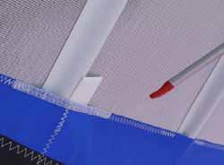
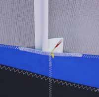
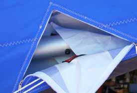
11 SECTION 3 / USAGE Wing Assembly (Rigging) The wing assembly is the start of a thorough PREFLIGHT. The assembly operation must be carried out unhurriedly, without using force and methodically: position the wing nose into wind, open the cover Turn the wing over, Control frames on the ground (on canvas, grass, a smooth surface) remove the cover fit the king-post to the keel, between the cross spar tensioning cables (2) hang the upper-longitudinal rear cable near the king-post, without crossing the cables Note: the part small diameter of the hook will be directed upwards (3) position the nose batten on the head of the CHC 6 front screw pull the leading edges outwards, grasping them in the middle, without raising or forcing them (1) pull the control frame outwards, checking that no cable passes inside the frame fit the control bar using the M8 bolt (wing nut + safety ring) Note: preferably position the wing nut towards the nose of the wing so as not to tear the front seat cover when the control bar rests against it slide upper wing surface battens into their respective sleeves Note: the leading edge batten ends are colour-coded, red for the port (left) side and black, green or white, for the starboard (right) side check the position of the side and longitudinal cables pull on the cross spars tensioning cables Note: to facilitate this operation, raise the tip of one of the leading edges to knee height (i.e. give the wing a little dihedral) lock the tension lever (or goose neck) using the pit-pin (2). Note: the end of the tension lever is divided, lock it immediately. On the level of the king post, the left tensioning cable of must be higher than that located on the right. tighten the upper surface battens, pass the shock-cord in double (4, 5). raise the wing by the back of the keel, by making it swivel on its bar of control tension the front cables and lock the tension lever using the pit-pin. place the nose of the gently on the ground, nose into wind slip the under-surface battens into their respective sleeves (6, 8). Note: the batten tip is spoon shaped, with the hollow side, cupped towards the leading edge (7). Red tip to the left; black, white or green, to the right insert the washout tubes (dive sticks) in the leading edge close the wing ends attach the nose cap. Note: the absence of the nose cap creates an internal pressure variation in the wing which causes fundamental changes in the wing profile and makes the wing heavier to control. Note: in moderate or strong winds secure the wing by its nose. Attaching the wing to the Airframe See the Airframe Instruction manual. Wing Disassembly (De-rigging) Follow the Wing Assembly procedure, except in reverse. Before placing the wing on the ground, the hang bracket protection on the top of the control frame must be fitted to the keel and the undersurface battens and the hang block remove (10). Before folding up both sides of the wing, to withdraw the washout tubes from their sockets and fold back them along the leading edge. MAUT DYN 450 Edition : June 2005 Section : 3-01


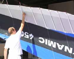
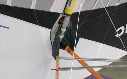
12 MAUT DYN 450 Edition : June 2005 Section : 3-02
13 Adjustments Hang Bracket Position : Hang Bracket Position: there are 4 hang bracket positions: The wing becomes faster «brisk» by moving the wing hitching cubes forward. In flight, the control bar, hands free (neutral bar position), will tend to move back from 3 to 5 centimeters per adjustment step. Position 4 (closest to the front) is the fastest. While parked, the control bar rests against the pilot seat. The wing becomes slower, more «placid» by moving the wing hitching cubes backwards. In flight, the control bar, hands free (neutral bar position), will tend to move forwards from 3 to 5 centimeters per adjustment step. Position 1 (closest the rear), is the most sedate. While parked, the control bar rest against the wing stop on the top of the mast/pylon. Two sets of horizontally drilled holes, spaced at 28 mm centers, allow 2 hang positions, positions 1 and 3. The other two hang positions are obtained (2 and 4) by turning the two keel blocking rings 90. The two nylon blocking rings restrict the forward/aft movement of the hitching cubes. The blocking ring drill holes are spaced at 14 mm centres. The M6 Nylock self-locking nuts MUST be changed after each use. Each position change will increase or decrease the hands free speed by 5 km/h to 7 km/h. Position n 2 is the standard position (i.e. the position where roll and pitch is most consistent.) Address It is not recommend that the Aircraft be flown at MTOW in position n 1, because the hands free speed will be very close to the wing s stall speed. Control deflections must be subtle. The effort required to pull the control bar in will be more significant than in hang position n 2. At MTOW in position n 4, full front, the effort required to push the control bar out will be more significant than in position of centering n 2. This effort MUST especially be taken into account during takeoff and landing. Washout: the wing tip assembly is restrained using a screw. This adjustment is carried out during the wing flight tests before delivery. It does not have to be changed. Tension: to correct a slight tendency of the wing to fly to the right or the left in flight, it is only necessary to modify the tension of the shock cord of the upper-surface wing battens. Work on the first 8 battens from the keel, by 2 battens at a time, conduct a flight test after each batten retension. Tighten the inside wing (the wing which is lower in a turn). Loosen the outside wing (the wing which is higher in a turn) Tightening the shock-cords causes the batten to compress, which increase the thickness of the wing profile, increasing lift and therefore correcting the tendency to turn. The tension of the shock-cords of the three last (outboard) upper surface battens, as well as the batten at the wing tip (thicker cord), must be tight and identical on both the right and the left. (CF Vibration). Tension adjustments to the end of the leading edges (CHC 6 Screw) must be carried out identically on both the right and on the left, at scheduled maintenance times (CF section 4 01). Note: the influence this these adjustments on flight symmetry is unimportant. MAUT DYN 450 Edition : June 2005 Section : 3-03
14 Non-Symmetrical Flight: correction example If your wing tends to fly to the right You could tighten the shock cord on this side or you could slacken the shock cord on this side Vibration: the appearance, at high speed, of a vibration of the wing trailing edges is a result of insufficient tension on the shock cord of the battens where the vibration occurs. Modification: No modification should be undertaken on the wing. The batten profile (curve) should not have to be modified. MAUT EN DYN 450 Edition : June 2005 Section : 3-04
15 PREFLIGHT INSPECTION: A Pre-flight inspection must be done before each flight, without haste and methodically. Any Microlight (ULM) Flight Training Course teaches that the beginning of Flight Safety is a good and thorough PREFLIGHT. You must apply this teaching. Note: the cables should be checked by sliding your hand along them; also turn the swaged cable end hearts to detect signs of wear. Start at the nose of the wing. Raise the nose cap and check the security of the connection of the upper and lower cables Verify the security of the tension lever, the pit pin and its safety cap. Replace the nose cap. Move towards the end of the wing sliding you hand along the leading edge to check that it is not deformed, and that the leading edge fabric does not show any trace of impact, of tears or non-standard wear. In the event of abnormal wear or of impact marks, the tubes of leading edge MUST BE CHECKED. The wing MUST be disassembled. Check the sail is securely fastened at the wingtip (2 countersunk M6 bolts + 1 CHC 6 bolt which is protected by a cap rubber) Open the hatch at the wing tip and verify that the washout tube/dive stick is correctly inserted in the leading edge tube then immediately close the hatch again Walking towards the keel and visually check the batten position and the shock cord (5). Open then close under-surface hatch to verify the condition of the leading edge / cross spar connection, upper and lower side cables, the protection.(9) Check the state of the luff cables et their position on the trailing edge and at the head of mast. The larger diameter end of the hook of the luff lines should be downwards (3). Check that no cables are entangled or around the mast. At the back of the keel, check that the upper cable and the lower cables, the two cross spar tensioning cables, the security and the position of the tensioning lever, the security of the pit pin and the safety cap (2), Check the airworthy condition of the keel pocket of skittle and the safety strap Check that the mast is properly seated, positioned in the middle of the 2 cross spar tensioning cables. Note : the right cable is lower than the left. Slide your hand along the lower rear stay cables to the control bar Check the control bar knuckles and their airworthiness Slide your hand along the lower front stay cables to the nose of the wing Check the other wing in an identical manner. MAUT EN DYN 450 Edition : June 2005 Section : 3-05
16 Check the control frame side tubes. Check that the upper surface retension strap, in front of the top of the control frame, is slipped between the fabric of the under-surface and keel tube. Only this section of the strap will be visible. Check the state of the cross spar safety strap on the keel. Verify the base/wing connection (hang bracket) (CF MAUT EN of Airframe) Wing Use Pitch : when the pilot pushes on the control bar, it raises the nose of the wing what increases the incidence and involves a reduction in speed. When the pilot draws the control bar towards them self, the nose of the wing lowers, which decreases the angle of incidence and increases speed. Roll: when the pilot pushes the control bar laterally, it moves the airframe under the wing, initiating a rolling movement (Control Bar of operated towards the right centre of gravity moved towards the left => roll towards the left). Yaw : the yaw is induced by the roll action caused by the pilot s roll input. When the aircraft is placed in a turn a light thorough progressive increase in pitch must be initiated. (The control bar pushed out by approximately to 5 to 8 cm), in order to balance the turn. An increase in engine power is necessary to maintain the altitude. The increase in pitch and engine power will be more pronounced as the angle of bank of the turn increases. Reminder: Angle of Bank of 60 increases the load factor to 2 g Takeoff : the wing held horizontal with a very slight pitch angle. When airspeed reaches 50 km/h, increase the angle of incidence of the wing gradually. As soon as the wheels leave the ground, draw the control bar back (towards the pilot) in order to preserve a trajectory parallel with the runway. Let the Microlight (ULM) accelerate up to 80 km/h before climbing out. The climb out airspeed should not be lower than 75 km/h. When entering Straight and Level flight, power reduction should be progressive. Avoid any brutal reduction in power or engine shutdowns whilst on climb out: the alteration of course will be a function of the pitch of the aircraft. Reminder: pitch maximum + / 45 Cruise: bar neutral, the wing flies at a speed which is a function of the hang point on the keel, weight in flight and of the state of the air (CF Hang-Bracket Positioin section 3-03 as well as the wing Test Form). The VNE is fixed at 160 km/h. The manoeuvring speed or in turbulent air MUST not exceed 110 km/h. Landing: the approach should take place with an idling engine, at a speed equal to 1.3 the VSO, approximately 85 km/h. as the ground approaches push the control bar incrementally forward to decrease speed by increasing the angle of incidence of the wing. The wheels will touch down at less that 65 km/h. The wind conditions (gradient), turbulence, altitude, the temperature (variation in temperature), the load, are some of the many factors which will lead the pilot to increase the approach speed. Short takeoffs and landings: The techniques are overall identical to that which is explained above. On takeoff, apply maximum power before releasing the brakes then gradually increase pitch until at maximum. With the landing the approach speed will be reduced and the round-off begun earlier in order to touch the aft wheels in a full pitch-up position, at the stalling speed. Pull the control bar in to the maximum, while decelerating; which will make it possible to benefit from aerodynamic braking. MAUT- EN DYN 450 Edition : June 2005 Section : 3-06
17 Stalls : The stall will be all the more easy to reach when the hang position of the wing is in back position and with significant load. The onset of a stall appears as an intensification of the effort required to push the control bar out and some jolts/bumps. It is enough to decrease the pressure on the control bar so that the wing gains airspeed. The loss of altitude will be limited to a few tens of meters. If the bar pressure is maintained throughout the stall, the stall can become a more pronounced manoeuvre. A non-symmetrical (wing drop left or right) is possible. All stall practice should be carried out with a minimum of 1500 ft altitude (AGL), in a gentle descent, engine power reduced, with a gradual and controlled reduction in speed, with a simultaneous and progressive outward pressure on the control bar. Violently pulling the control bar towards oneself during a stall or attempting an aggravated stall during a climb increases the risk of tumbling, this is due to the poor pitch damping effect of the weight shift delta wings. NOTE: It is PROHIBITED to undertake a series of connected stalls. Load: Any increase of load will increase the effort required to pilot the aircraft, as well as an increase in stalling speed. The control bar neutral position will be slightly forward. Rain, dew, frost, ice: any layer water on the leading edge and the upper wing surface disturbs the air flow. The stall angle of the wing will be decreased. The associated stall speed will increase by approximately 10 km/h. If you wipe the leading edges before the flight, wipe both sides of the wing (right and left). Strong wind: when taxiing into wind hold the wing flat, control bar drawn slightly towards the pilot. When taxiing with the wind: push the control bar forwards in order to avoiding having the aircraft being blown over. Crosswind: lower the into-wind wing slightly. Grip the control bar firmly: it may be necessary to exert significant force to maintain control of the wing. Tie-down: Gentle breeze: it is possible to leave the wing on the airframe, lowering a wing into the wind, or face the Microlight, with the control bar secured to the seat, into wind (the angle of attack will therefore be nil). The control bar is secured by fastening the control bar against the front seat using the seatbelt. Moderate wind: it is preferable that the wing be lowered and to place the control bar on the ground close to the front wheel. (Nil angle of attack). The wing should be secured to the ground at both ends of the keel and by the outside cross spars, which are accessible through the hatches in the wing s under-surface. The control bar should be secured to the the nose wheel, and the keel behind the mast/pylon. In the event of seriously degraded weather conditions: the wing should be lowered to the ground, facing into wind, battens removed, sail de-tensioned. Weighted down or firmly secured to the ground. MAUT EN DYN 450 Edition : June 2005 Section : 3-07
18 SECTION 4 / MAINTENANCE - GUARANTEES Maintenance Caution: the two outer sections of the leading edge are not identical. They must be attached to their correct leading edge tube. If they are reversed it will modify the angle of the washout tubes ( dive sticks ), possibly making the wing uncontrollable. Transport: one of the principal causes of wear on the wings is vehicle transport. To minimize this risk, use the provided protective padding during the disassembly and folding of the wing, use a ladder (or similar) sufficiently padded, and avoid having the wing overhang the ends. Maintenance: cleaning is done with mild soap and water. Regularly wash the wing in fresh water if you fly at the seaside. In this case the frequency of the periodic maintenance must be increased. In tropical regions, it can be useful to clean with a liquid fungicide. After cleaning, the wing must be allowed to dry. It MUST NEVER placed in its cover when it is wet. Glue spots, of an old registration marking, for example, can be effectively removed by using a rag soaked in trichloroethylene. Storage: in a dry dark area, or safe from the light (heat and UV), after making sure that the the wing is completely dry. Ageing: exposure to ultraviolet radiation emitted by the sun and reflected by the moon, cause the ageing of the fabric and the seams. As far as possible, park your aircraft under shelter, out of the sun, between flights. Four upper-surface fabric samples, composed of two fabric parts joined by a seam, are stitched into the trailing edge, on both sides of the center of the wing. These bands can be cut out, if necessary, during periodic maintenance in order to carry out resistance tests. Periodic Checks: Every 50 hours you must visually check: The luff lines, the mast attachment hook and the trailing edge connections All wing cables, the stainless swages and hearts The nose plates The upper-surface and keel-pocket (center of the wing) seams All articulation and attaching bolts The batten shock cord The tension (very firm) of the outboard battens After any violent or «heavy» landing, it is imperative that you check: The nose plates the straightness of the leading edges (a disassembly is necessary) The straightness of the keel The straightness of the control frame riser tubes The straightness of the control bar, The straightness of the cross spars The profile of the battens (between right side and left side) The nuts and bolts The absence of any deformation thimble hearts of all the cables The seams of the sail, in particular at the center of the wing The hang assembly MAUT EN DYN 450 Edition : June 2005 Section : 4-01
19 Revision: The complete revision wing is MANDATORY every 200 hours of flight or every 2 years. The side cables * MUST be changed every 400 hours or 6 years. The revision is carried out by a complete disassembling of the wing structure, the replacement of all nuts and bolts *, a check of all the different components: straightness of the tubes, the state of the cables, checking of the batten profiles, etc. * Nuts, bolts, cables, tubes, plates, knuckles, sail, MUST be replaced by original parts sold by DTA SARL, and refitted in an identical manner. Any used NYLOCK self-locking nut must be replaced and be fitted using standard Loctite. Guarantee The guarantee of DTA SARL on the wing is limited to a duration of one (1) year starting from the date on the commercial invoice. During the delivery, the delivery documentation must be filled out and signed by the customer. The guarantee only applies if the use of the aircraft conforms to the instructions stated in the User's manuals or any technical document stating the conditions of use of the aircraft given to the purchaser. The breaking of any regulatory provisions of the Civil Aviation Code or any related legislation of the country of registration of the aircraft, having as a consequence an accident or incident, exonerates DTA SARL (a limited liability company) of any guarantee with respect to the operator/owner/pilot infringing said Civil Aviation regulations or provisions. Normal wear of renewable components is not included in any guarantee. Any modification of the aircraft by the purchaser, as well as the replacement of parts by parts not being original, will involve the forfeiture of the guarantee by DTA SARL unless the modification has been approved, in writing, by DTA SARL. The guarantee is limited to the replacement or repair in the workshops of DTA SARL or by a workshop approved by DTA SARL. The guarantee covering the engine and its accessories, the propeller, the accessories not built by DTA SARL, will be guaranteed by the conditions and limits fixed by the manufacturers of those products. The obligations of DTA limited liability companies stated above constitute the limit of the granted guarantees. MAUT EN DYN 450 Edition : June 2005 Section : 4-02
20 SECTION 5 / ADDITIONAL DOCUMENTS Nomenclature Item Description Item Description Cables Bolts, shackle, carabinier E1030 CROSS SPAR WIRES 450 (2) E MM LENGHT Ø 6 STAINLESS PIN CRS CHANNEL E1031 CROSS SPAR WIRES 450 E7014 W STAINLESS STEEL TENSIONNING SHACKLE E1032 UPPER FRONT WIRE 450 E7021 RUBBER EXTENSIBLE SPRING FOR WHASHOUT TUBE E1033 UPPER REAR WIRE 450 E7025 KINGPOST CARABINIER E1034 SHORT LUFF LINE 450 E7026 LM SHORT STAINLESS STEEL SHACKLE E1035 MIDDLE LUFF LINE 450 E7029 LM MIDDLE STAINLESS STEEL SHACKLE E1036 LONG LUFF LINE 450 E MM LENGHT STAINLESS STEEL PUSH-PIN E1037 LOWER FRONT WIRE 450 E7160 FHC 8X100/12 CRS / CRS JUNCTION E1038 FRONT LOWER SIDE WIRE 450 E7161 FHC 6X78/9 REAR NOS PLATE/KEEL TUBE E1039 REAR LOWER SIDE WIRE 450 E7162 FHC 6X76/10 FRONT NOS PLATE / KEEL TUBE E1159 LOWER REAR WIRES 450 (2) E7163 FHC 6X85/11 OUTSIDE CROSS SPAR SLEEVE E1194 CROSS SPAR WIRE 450 E7164 FHC 6X65/25 TENSIONNING CHANNEL / KEEL TUBE Tubes E7165 FHC 6X70/12 CHANNEL/KEEL/UPPER REAR WIRE E2080 CONTROL FRAME BASE TUBE E7166 FHC 6X70/25 SAIL / TIP LEADING EDGE E2091 OUTSIDE KEEL SLEEVE E7167 CHC 6X42/10 CTR KNUCKLE/LOWER SIDE WIRE E2092 KEEL 450 E7170 CHC 8X98/13 CROSS SPAR PLATE E2093 LEFT CROSS SPAR 450 E7171 CHC 8X78/12 NOSE PLATE / LEADING EDGE E2094 RIGHT CROSS SPAR 450 E7172 CHC 6X34/11 MANILLE / COL DE CIGNE NEZ E2095 RIGHT LEADING EDGE FRONT SECTION 450 E7173 CHC 6X73/12 L.E / CROSS SPAR CHANNEL E2096 LEFT LEADING EDGE FRONT SECTION 450 E7174 CHC 10X80/24 RCROSS SPAR / LEADING EDGE JOINT E2097 TIP LEADING EDGE 450 E7175 CHC 6X38/13 SHACKLE / CROSS SPAR LOCK E2100 WHASHOUT TUBE 450 E7176 CHC 6X80/25 PLASTIC CENTERING RING / KEEL E2195 RIGHT LEADING EDGE REAR SECTION 450 E7177 CHC 6X80/12 CONTROL FRAME CHANNEL / KEEL E2196 LEFT LEADING EDGE REAR SECTION 450 E7178 CHC 6X37/8 CONTROL FRAME SIDE / UPPER KNUCKLE E3210 TIP TENSIONNING RIB E7179 CHC 10X90/14 CTR FRAME / CTR FRAME CHANNEL E3211 LOWER RIB N E7180 CHC 8X38/12 CTR FRAME BASE / LOWER KNUCKLE E3213 NOSE RIB E7181 CHC 8X38/12P. CTR FRAME BASE / LOWER KNUCKLE E3214 UPPER RIB N E7182 CHC 8X62/12 CTR FRAME SIDE / BASE TUBE KNUCKLE E4090 KINGPOST 450 E7183 CHC 6x57/13 CTR FRAME SIDE / LOWER KNUCKLE E4101 CONTROL FRAME SIDE E7184 CHC 6X80/36 TIP LEADING EDGE TENSIONNING Hard ware Sail, strap, plastic parts E5121 CROSS SPAR PLATE E8043 CROSS SPAR SAFETY STRAP E5122 SPAR PLATE COUNTERSINK E8218 NOSE CONE E5125 CROSS SPAR TENSIONNING CHANNEL E8221 JOINT CROSS SPAR PROTECTIVE FABRIC E5126 NOSE PLATE 450 E8222 JOINT LEADING EDGE / CROSS SPAR PROTECTIVE E5128 SHORT LOCK E8225 CROSS SPAR / KEEL STRAP E5131 LOWER FRONT WIRES CHANNEL E8232 SAIL 450 E5134 CONTROL FRAME CHANNEL E8601 LEADING EDGE RODHOID E5137 LEADING EDGE / CROSS SPAR CHANNEL E9061 PLASTIC KINGPOST UPPER E6103 CONTROL FRAME SIDE LOWER KNUCKLE 450 E9062 PLASTIC KINGPOST LOWER E6130 ALUMINIUM WING TIP PLUG E9064 CONTROL FRAME SIDE FITTING E X10/28 CONTROL FRAME CHANNEL SPACER E9065 RUBBER CONTROL FRAME BASE TUBE SHOE E X8/7 LOWER FRONT / REAR WIRES SPACER E9066 HANG BLOCK E6135 CONTROL FRAME SIDE UPPER KNUCKLE E9067 NEVERKING E6136 ALUMINIUM 10/50 L.E / CRS SADDLE WASHER E9072 TUBE Ø 25 MM PLASTIC SADDLE WASHER E X10/23.7 L.E / CRS CHANNEL SPACER E9075 TUBE Ø 48 MM WRAPING END PLUG E X8/48 CRS/CRS SPACER E9079 TUBE Ø 50 MM PLASTIC SADDLE WASHER E6141 CONTROL FRAME BASE TUBE KNUCKLE 450 E9102 PLASTIC CENTERING RING F0186 CONTROL FRAME BASE TUBE SLEEVE MAUT DYN 450 Edition : June 2005 Section : 5-01
21 Maintenance Log Date Hours Operations carried out Sign MAUT DYN 450 Edition : June 2005 Section : 5-02
INSTRUCTION AND MAINTENANCE HANDBOOK. Wing Type FUN 14. II) Technical specifications - Performances
 Technical specifications - Performances") INSTRUCTION AND MAINTENANCE HANDBOOK Wing Type FUN 14 I) Drawings II) Technical specifications - Performances III) Instructions for use IV) Maintenance Instruction and Maintenance Handbook FUN 14 EDITION
INSTRUCTION AND MAINTENANCE HANDBOOK Wing Type FUN 14 I) Drawings II) Technical specifications - Performances III) Instructions for use IV) Maintenance Instruction and Maintenance Handbook FUN 14 EDITION
INSTRUCTION AND MAINTENANCE HANDBOOK. Wing Type MILD 16. II) Technical specifications - Performances
 Technical specifications - Performances") INSTRUCTION AND MAINTENANCE HANDBOOK Wing Type MILD 16 I) Drawings II) Technical specifications - Performances III) Instructions for use IV) Maintenance Instruction and Maintenance Handbook MILD 16 EDITION
INSTRUCTION AND MAINTENANCE HANDBOOK Wing Type MILD 16 I) Drawings II) Technical specifications - Performances III) Instructions for use IV) Maintenance Instruction and Maintenance Handbook MILD 16 EDITION
INSTRUCTION AND MAINTENANCE HANDBOOK. Wing Type FUN 450. Technical specifications - Performances
 INSTRUCTION AND MAINTENANCE HANDBOOK Wing Type FUN 450 I) Drawings II) Technical specifications - Performances III) Instructions for use IV) Maintenance Instruction and Maintenance Handbook FUN 450 EDITION
Wing Type ixess 15 and ixess Training
 INSTRUCTION AND MAINTENANCE HANDBOOK Wing Type ixess 15 and ixess Training I) Drawings II) Technical specifications - Performances III) Instructions for use IV) Maintenance Instruction and Maintenance
Wing assemblyfinal Master 4/29/04 11:20 PM Page 1. Issued January 1, Sabre Aircraft. Assembly Manual. Sabre 16ss Wing
 Wing assemblyfinal Master 4/29/04 11:20 PM Page 1 Issued January 1, 2002 Sabre Aircraft Assembly Manual Sabre 16ss Wing Wing assemblyfinal Master 4/29/04 11:20 PM Page 2 1. 2. 1. Unzip the cover and remove
INSTRUCTION AND MAINTENANCE HANDBOOK. Wing Type ifun 16
 INSTRUCTION AND MAINTENANCE HANDBOOK Wing Type ifun 16 I) Drawings II) Technical specifications - Performances III) Instructions for use IV) Maintenance GDMANiFUN16-1G Version 0010 PAGE: 1 I) Drawings
INSTRUCTION AND MAINTENANCE HANDBOOK. Wing Type ifun 13
 INSTRUCTION AND MAINTENANCE HANDBOOK Wing Type ifun 13 I) Drawings II) Technical specifications - Performances III) Instructions for use IV) Maintenance GDMANiFUN13-1G Version 0010 PAGE: 1 I) Drawings
TRIKE WING PROFI TL MANUAL
 TRIKE WING PROFI TL MANUAL Size: Manufactured by: AEROS Ltd. Tel: (380 44) 455 41 18, Post-Volynskaya St. 5 Fax: (380 44) 455 41 16 Kiev 03061 E-mail: aerosint@aerosint.kiev.ua, UKRAINE http://www.aeros.com.ua
XI.C. Power-Off Stalls
 References: FAA-H-8083-3; POH/AFM Objectives Key Elements Elements Schedule Equipment IP s Actions SP s Actions Completion Standards The student should develop knowledge of stalls regarding aerodynamics,
TOPLESS OWNER S MANUAL
 LA MOUETTE GLIDERS TOPLESS OWNER S MANUAL CONTENTS 1. Description of design--------------------------------------------- 2 2. Specifications ----------------------------------------------------- 2 3. Operating
Falcon 3 145, 170, 195 and Tandem Owner / Service Manual
 Falcon 3 145, 170, 195 and Tandem Owner / Service Manual January 2007 - Second Edition Removing The Sail From The Airframe And Short Packing The Glider Many maintenance and repair procedures will require
XI.B. Power-On Stalls
 XI.B. Power-On Stalls References: AC 61-67; FAA-H-8083-3; POH/AFM Objectives Key Elements Elements Schedule Equipment IP s Actions SP s Actions Completion Standards The student should develop knowledge
BRAKE WINCH RUP 503-[T/BT] EQUIPMENT FOR LIFTING LOADS. AT 053-[T/BT] xx
![BRAKE WINCH RUP 503-[T/BT] EQUIPMENT FOR LIFTING LOADS. AT 053-[T/BT] xx](/thumbs/88/115945274.jpg "BRAKE WINCH RUP 503-[T/BT] EQUIPMENT FOR LIFTING LOADS. AT 053-[T/BT] xx") Reference number: BRAKE WINCH RUP 503-[T/BT] EQUIPMENT FOR LIFTING LOADS DESIGNATED USE The brake winch RUP 503-[...]T series is a load lifting / lowering device. Device is equipped with safety brake for
Reference number: BRAKE WINCH RUP 503-[T/BT] EQUIPMENT FOR LIFTING LOADS DESIGNATED USE The brake winch RUP 503-[...]T series is a load lifting / lowering device. Device is equipped with safety brake for
Eurofly Snake Pilot Operating Handbook
 Eurofly Snake Pilot Operating Handbook Version 1.0 (March 2018) Congratulations on purchasing the nanolight Eurofly Snake trike. Designed and manufactured by a company with over 30 years of experience
7130 Lancer Rear Drive Magnetic Commercial Indoor Cycling Bike
 7130 Lancer Rear Drive Magnetic Commercial Indoor Cycling Bike Owner s Manual Made in Taiwan INDEX IMPORTANT SAFETY INFORMATION... 1 EXPLODED DRAWING... 2 PARTS LIST... 3 ASSEMBLY INSTRUCTION... 4-9 USER
INSTRUCTION MANUAL. January 23, 2003, Revision 0
 INSTRUCTION MANUAL Model 810A In-Vitro Test Apparatus for 310B Muscle Lever January 23, 2003, Revision 0 Copyright 2003 Aurora Scientific Inc. Aurora Scientific Inc. 360 Industrial Parkway S., Unit 4 Aurora,
Логотип. Hangglider PHANTOM. Manual
 Логотип Hangglider PHANTOM Manual Kiev, Ukraine 2005 TABLE OF CONTENTS Section 1. General information 1.1. Introduction 1.2. Main data 1.3. Operation limitations 1.4. Flying tests Section 2. Set up procedure
User Manual Important, read before use!
 EN User Manual Important, read before use! SMART Congratulations on your new rollator! Volaris Smart The Volaris Smart will make your life easier in many ways. We ask you to read carefully through this
Pectoral Machine. User manual E S S E N T I A L S T R E N G T H
 E L E M E N T and the cable E S S E N T I A L S T R E N G T H User manual 1 and the cable and The identification plate of and manufacturer, affixed on the back panel of the weight stack, gives the following
Brief Maintenance Manual DAR-Solo
 Brief Maintenance Manual DAR-Solo Sofia 2009 Page: 1 TABLE OF CONTENTS Introduction 3 Limitations and safety information 4 General view of DAR-Solo prototype 7 Technical Data 8 Inspection before and after
NORMAL TAKEOFF AND CLIMB
 NORMAL TAKEOFF AND CLIMB CROSSWIND TAKEOFF AND CLIMB The normal takeoff is one in which the airplane is headed directly into the wind or the wind is very light, and the takeoff surface is firm with no
CIVIL AIR PATROL United States Air Force Auxiliary Cadet Program Directorate. Cessna 172 Maneuvers and Procedures
 CIVIL AIR PATROL United States Air Force Auxiliary Cadet Program Directorate Cessna 172 Maneuvers and Procedures This study guide is designed for the National Flight Academy Ground School. The information
Aerodynamic Terms. Angle of attack is the angle between the relative wind and the wing chord line. [Figure 2-2] Leading edge. Upper camber.
![Aerodynamic Terms. Angle of attack is the angle between the relative wind and the wing chord line. [Figure 2-2] Leading edge. Upper camber.](/thumbs/82/86661300.jpg "Aerodynamic Terms. Angle of attack is the angle between the relative wind and the wing chord line. [Figure 2-2] Leading edge. Upper camber.") Chapters 2 and 3 of the Pilot s Handbook of Aeronautical Knowledge (FAA-H-8083-25) apply to powered parachutes and are a prerequisite to reading this book. This chapter will focus on the aerodynamic fundamentals
Chapters 2 and 3 of the Pilot s Handbook of Aeronautical Knowledge (FAA-H-8083-25) apply to powered parachutes and are a prerequisite to reading this book. This chapter will focus on the aerodynamic fundamentals
QUALITY ALUMINUM BOAT LIFTS, INC. INSTRUCTIONS. Dominator Lake Lift
 INSTRUCTIONS Dominator Lake Lift PHONE:251-986-3882 * FAX:251-986-3136 QABLDOMINATORINST.2014 P a g e 1 Quality Aluminum Boat Lifts, INC. Installation Instructions: Dominator Lake Lift Thank you for your
PERFORMANCE MANEUVERS
 Ch 09.qxd 5/7/04 8:14 AM Page 9-1 PERFORMANCE MANEUVERS Performance maneuvers are used to develop a high degree of pilot skill. They aid the pilot in analyzing the forces acting on the airplane and in
CHAPTER 9 PROPELLERS
 CHAPTER 9 CHAPTER 9 PROPELLERS CONTENTS PAGE How Lift is Generated 02 Helix Angle 04 Blade Angle of Attack and Helix Angle Changes 06 Variable Blade Angle Mechanism 08 Blade Angles 10 Blade Twist 12 PROPELLERS
MANUAL SEALLESS STEEL STRAPPING TOOL MODEL A
 OPERATION MANUAL / SPARE PARTS LIST MANUAL SEALLESS STEEL STRAPPING TOOL MODEL A337.0001 13.1912.01 13191201.en/MAS/ 10.02 INDEX PAGE 1 SAFETY INSTRUCTIONS 2 2 WARRANTY CONDITIONS AND LIABILITY 4 3 APPROPRIATE
HANG GLIDER OWNER / SERVICE MANUAL. Size: Date of production: Serial number: Manufactured by: AEROS Ltd., Post-Volynskaya St. 5., Kiev, 03061, UKRAINE
 HANG GLIDER OWNER / SERVICE MANUAL Size: Date of production: Serial number: Manufactured by: AEROS Ltd., Post-Volynskaya St. 5., Kiev, 03061, UKRAINE Tel: (380 44) 455 41 18, Fax: (380 44) 455 41 16 E-mail:
LAMINAR Hanggliders - User's Manual Page # 1 / /05/00 Rev.99, jul. Laminar. Instructions Manual. Rev
 LAMINAR Hanggliders - User's Manual Page # 1 / 25 Laminar Instructions Manual Rev.2000.1 1 LAMINAR Hanggliders - User's Manual Page # 2 / 25 Congratulations on buying an Icaro 2000 hang-glider! We re confident
BELT DRIVE INDOOR CYCLING BIKE SF-B1712 USER MANUAL
 BELT DRIVE INDOOR CYCLING BIKE SF-B1712 USER MANUAL IMPORTANT! Please retain owner s manual for maintenance and adjustment instructions. Your satisfaction is very important to us, PLEASE DO NOT RETURN
BELT DRIVE PREMIUM INDOOR CYCLING BIKE SF-B1509 USER MANUAL
 BELT DRIVE PREMIUM INDOOR CYCLING BIKE SF-B1509 USER MANUAL IMPORTANT! Read all instructions carefully before using this product. Retain owner s manual for future reference. For customer service, please
600 / 600FC OWNER'S MANUAL
 PROGRESSION 600 / 600FC OWNER'S MANUAL Issue 2 / Version E - Dec. 10, 1997 Copyright 1997 GAMMA Sports - All Rights Reserved PROGRESSION 600 / 600FC OWNER'S MANUAL TABLE OF CONTENTS PAGE 1... WARRANTY
MAGNETIC INDOOR CYCLING BIKE
 MAGNETIC INDOOR CYCLING BIKE SF-B1805 USER MANUAL IMPORTANT! Please retain owner s manual for maintenance and adjustment instructions. Your satisfaction is very important to us, PLEASE DO NOT RETURN UNTIL
LAA TYPE ACCEPTANCE DATA SHEET TADS 315 EV-97 AND EV-97A EUROSTAR. Issue 6 SB EV97-UK-08 and 09 added dated
 Issue 6 SB EV97-UK-08 and 09 added dated 26.3.08 1. UK contact Nigel Beale, Cosmik Aviation, Burnside, Deppers Bridge, Southam, Warks, CV47 2SU. Tel: 07940 266521. E-mail: cosmik@skydrive.co.uk 2. Description
Installation and Training Manual
 AirForce1 Tower Kit Installation and Training Manual FuturEnergy Limited Ettington Park Business Centre Stratford upon Avon CV37 8BT +44 (0)1789 451070 Table of Contents Safety Notes... 3 Parts Supplied
FIREFIGHTING EQUIPMENT
 FIREFIGHTING EQUIPMENT User Manual ANTENOR 3000 Base or portable Trailer DOC 1974 En Rev.B - 22/10/13 Tel : 03 25 39 84 78 - Fax : 03 25 39 84 90 - Email : france@pok.fr - Web : www.pok.fr Identification
contents introduction
 contents 1. Contents 2. Introduction 3. Parts Description 4. Personal Safety 5. Transportation & Assembly 6. Adjustments for Comfort 7. Brake Operation 8. Care and Maintenance 9. Specification 10. Warranty
BASIC AIRCRAFT STRUCTURES
 Slide 1 BASIC AIRCRAFT STRUCTURES The basic aircraft structure serves multiple purposes. Such as aircraft aerodynamics; which indicates how smooth the aircraft flies thru the air (The Skelton of the aircraft
RS Important Notes. Contact. Bicycle Maintenance Stand instructions manual. Warranty Period : 1 year (from the date of your purchase)
") Warranty Period : 1 year (from the date of your purchase) RS-1700 Bicycle Maintenance Stand instructions manual (ver.1.2 2016/12) For more details, read the attached "Minoura Limited Warranty Policy" card.
Warranty Period : 1 year (from the date of your purchase) RS-1700 Bicycle Maintenance Stand instructions manual (ver.1.2 2016/12) For more details, read the attached "Minoura Limited Warranty Policy" card.
LITERIDER 2&3 IMPORTANT WARNING. 2Bike (1x) Bolt (1x) Nut (1x) Small Hex Wrench (1x)
 Bolt (1x) Nut (1x) Small Hex Wrench (1x)") LITERIDER 2&3 3 Bike (1x) Bolt (1x) Flat Washer (2x) Nut (1x) Large Hex Wrench (1x) 2Bike (1x) wrench (1x) Small Hex Wrench (1x) keys (2x) Long Strap (1x) 2-Zip Strips (6x) 3-Zip Strips (9x) Wheel strap
LITERIDER 2&3 3 Bike (1x) Bolt (1x) Flat Washer (2x) Nut (1x) Large Hex Wrench (1x) 2Bike (1x) wrench (1x) Small Hex Wrench (1x) keys (2x) Long Strap (1x) 2-Zip Strips (6x) 3-Zip Strips (9x) Wheel strap
BELT DRIVE INDOOR CYCLING BIKE SF-B1712
 BELT DRIVE INDOOR CYCLING BIKE SF-B1712 USER MANUAL IMPORTANT! Read all instructions carefully before using this product. Retain owner s manual for future reference. For customer service, please contact:
LIGHTWEIGHT TRIWALKER OWNER S HANDBOOK
 LIGHTWEIGHT TRIWALKER OWNER S HANDBOOK Triwalker Owner s Handbook (Z25987 Rev A) Page 1 of 12 CONTENTS 1. Contents 2. Introduction 3. Parts Description 4. Personal Safety 5. Adjustments for Comfort 6.
INSTALLATION MANUAL JAPANESE ENGLISH GERMAN FRENCH ITALIAN SPANISH. Before installation. Installation INSTALLATION MANUAL: B700
 Thank you for purchasing this product. Please read this installation manual before assembling and using the product, and be sure to use the product properly. An accident or injury can result if the product
Ottawa Remote Control Club Wings Program
 + Ottawa Remote Control Club Wings Program Guide line By Shahram Ghorashi Chief Flying Instructor Table of Contents Rule and regulation Quiz 3 Purpose of the program 4 Theory of flight Thrust 4 Drag 4
Bladerider X8 Assembly Help Notes
 2.1 Remove All Parts & Have Some Tools Handy Remove all items from the box and identify each part as per the packing sheet and check that nothing is missing. If there is something missing, please email
Item N o.: Item N am e:40cm Boys Rival Bike
 Item N o.:42272892 Item N am e:40cm Boys Rival Bike 9 bell 8 grip 30 crash pad 10 brake lever 26 wheel reflector 22 saddle 23 seat post 25 rear reflector 24 quick release 6 handle bar 7 stem 2 top tube
222 Schwinn Recumbent Exercise Bike Parts List Full Size Hardware Chart Product Illustration Assembly Instructions
 222 Schwinn Recumbent Exercise Bike Parts List Full Size Hardware Chart Product Illustration Assembly Instructions FITNESS SAFEGUARDS AND WARNINGS Before starting any exercise program, consult with your
C-130 Reduction in Directional Stability at Low Dynamic Pressure and High Power Settings
 C-130 Reduction in Directional Stability at Low Dynamic Pressure and High Power Settings The C-130 experiences a marked reduction of directional stability at low dynamic pressures, high power settings,
POWERED FLIGHT HOVERING FLIGHT
 Once a helicopter leaves the ground, it is acted upon by the four aerodynamic forces. In this chapter, we will examine these forces as they relate to flight maneuvers. POWERED FLIGHT In powered flight
4SE MODEL. High-tech walking aid for better life Nice Walker. Owner's Operator & Maintenance Manual. Senior friendly products
 www.nicetech.net Senior friendly products KC(Korea Certification) Q-Mark Certification Venture company Certification ISO 9001, 14001, 13485 Certification High-tech walking aid for better life Nice Walker
OPERATOR S MANUAL SPREADER. CSS, VNQ [For Combine Harvester AW82V] Original instructions
![OPERATOR S MANUAL SPREADER. CSS, VNQ [For Combine Harvester AW82V] Original instructions](/thumbs/90/102423265.jpg "OPERATOR S MANUAL SPREADER. CSS, VNQ [For Combine Harvester AW82V] Original instructions") OPERATOR S MANUAL SPREADER CSS, VNQ [For Combine Harvester AW82V] en Original instructions Introduction Introduction Please read this operator s manual before using your spreader. We would first like to
OPERATOR S MANUAL SPREADER CSS, VNQ [For Combine Harvester AW82V] en Original instructions Introduction Introduction Please read this operator s manual before using your spreader. We would first like to
DISCLAIMER: This scanned version of the Schweizer 2-33A Sailplane manual is provided without warranty of completeness or accuracy.
 DISCLAIMER: This scanned version of the Schweizer 2-33A Sailplane manual is provided without warranty of completeness or accuracy. It is solely as a service to builders of scale model aircraft who are
SG-7R46 SG-7R45 BR-IM41-R CJ-7S40 WARNING CAUTION SERVICE INSTRUCTIONS. Inter-7 Hub. Inter-M Brake Cassette joint NOTE:
 t WARNING It is important to completely understand the operation of your bicycle's brake system. Improper use of your bicycle's brake system may result in a loss of control or an accident, which could
THE OWNER'S MANUAL IS IN TWO VOLUMES: VOLUME 2 TECHNICAL SPECIFICATIONS - ASSEMBLY PROCEDURE ZODIAC
 CAUTION NOTICE: CAREFULLY READ THIS MANUAL BEFORE OPERATING YOUR BOAT. THIS OWNER S MANUAL IS IN TWO VOLUMES THAT MUST BE KEPT TOGETHER. THE OWNER'S MANUAL IS IN TWO VOLUMES: - VOLUME 1 DEALS WITH OPERATING
BR-2444 ROWING MACHINE
 BR-2444 ROWING MACHINE Important Safety Information Please keep this manual in a safe place for reference. 1. It is important to read this entire manual before assembling and using the equipment. Safe
ASSEMBLY MANUAL HOBIE CATSY
 ASSEMBLY MANUAL HOBIE CATSY HOBIE CAT EUROPE ZI Toulon Est, BP 50 8078 Toulon cedex 9, France Tel : + (0)9 08 78 78 - Fax : + (0)9 08 99 Email : hobiecat@hobie-cat.net - http://www.hobie-cat.net ASSEMBLY
TARGET MANUAL HANG GLIDER. Size: Manufactured by: AEROS Ltd. Post-Volynskaya St. 5. Kiev, UKRAINE
 HANG GLIDER TARGET MANUAL Rev. 2012.08.08 Size: Manufactured by: AEROS Ltd. Post-Volynskaya St. 5. Kiev, 03061 UKRAINE Tel: (380 44) 455 41 18 Fax: (380 44) 455 41 16 E-mail: aerosint@aerosint.kiev.ua
Build This World Record Fuselage Model
 Build This World Record Fuselage Model Here You Have Complete Instructions and Plans to Build a Plane of Sure-fire Performance that Established a World Record at the 1932 National Airplane Model Competition
Manual winch MANISTOR 100 and 200
 Manual wall winch Manual winch MANISTOR 100 and 200 Instruction manual UK 173-192.10-3 PRODUCT DEVELOPED AND MANUFACTURED ACCORDING TO NF EN 13157 STANDARD REGISTERED DESIGN To ensure the constant improvement
Installation, Operating, Inspection and Maintenance Instructions Ladder Climber s Safety System. Warning
 OWNER'S MANUAL Installation, Operating, Inspection and Maintenance Instructions Ladder Climber s Safety System Model # s: 6000, 6001, 6010 Warning You must read and fully understand all instructions, or
Thule RideAlong Mini Front Child Bike Seat
 Congratulations on your purchase of the Thule RideAlong Mini front child bike seat. This is a premium product with every detail carefully designed for high safety and easy use. We wish you and your child
Building Instructions ME 163 B 1a M 1:5 Turbine
 Building Instructions ME 163 B 1a M 1:5 Turbine Thank you for choosing our kit of the Me-163B. We ask you to read the instruction once in advance before building this kit in order to avoid mistakes. Make
Bob's Card Models and [Resources]
![Bob's Card Models and [Resources]](/thumbs/89/98525234.jpg "Bob's Card Models and [Resources]") + Bob's Card Models www.bobscardmodels.altervista.org and www.zealot.com [Resources] Sikorsky S-40 (1:72) The Sikorsky S-40 was an American amphibious flying boat built by Sikorsky in the early 1930s for
+ Bob's Card Models www.bobscardmodels.altervista.org and www.zealot.com [Resources] Sikorsky S-40 (1:72) The Sikorsky S-40 was an American amphibious flying boat built by Sikorsky in the early 1930s for
8MAY15 US RACK, Inc Falcon Drive, Madera, CA
 8MAY15 US RACK, Inc. - 2850 Falcon Drive, Madera, CA 93637-559-661-3050 INSTRUCTIONS for Bedrail-mounted MOTORCYCLE RACK, Model 2001-4TRA WARNING: Do NOT attempt to install or use this rack without following
Quattrocycle BV. Quattrocycle. User Manual. Last update February Quattrocycle BV Bremkant EJ Middelbeers. User Manual Quattrocycle 1
 Quattrocycle User Manual Last update February 2010 Quattrocycle BV Bremkant 6 5091 EJ Middelbeers User Manual Quattrocycle 1 Table of Contents Page Chapter 1: Introduction 3 Chapter 2: Instructions for
Assembly Instructions And User Guide
 EZ-1/EZ-CLASSIC QUADRIBENT By Blackbird Designs Inc. Mark 5.2 June 2011 Assembly Instructions And User Guide 1 The Quadribent is 2-seat, side-by-side, human powered vehicle that enables almost anyone to
INSTALLATION INSTRUCTIONS FOR ROLLOVER PROTECTION SYSTEM (ROPS)
") INSTALLATION INSTRUCTIONS FOR ROLLOVER PROTECTION SYSTEM (ROPS) This manual contains assembly, operating, maintenance and safety instructions for your ROPS. Before Installing the ROPS or operating a machine
INSTALLATION INSTRUCTIONS FOR ROLLOVER PROTECTION SYSTEM (ROPS) This manual contains assembly, operating, maintenance and safety instructions for your ROPS. Before Installing the ROPS or operating a machine
VERSA BIKE RACK INSTRUCTIONS
 VERSA BIKE RACK INSTRUCTIONS Models #8, 8 Important This rack is designed for use with a or. receiver hitch. The rack is designed to hold a maximum of two bicycles. Do not use it for anything other than
A. TO PREPARE THE MACHINE FOR USE.
 INSTRUCTION MANUAL FOR THE ML120 STRINGING MACHINE. CONTENTS: A. TO PREPARE THE MACHINE FOR USE. 1. The assembly of frame with console and tooltray. 2. Fixing the lever of the tension unit. 3. Putting
ROLLATOR (R6 and R8) OWNER S HANDBOOK
 OWNER S HANDBOOK") C O N T E N T S The Drive Medical lightweight 4- wheeled rollator is designed to aid the user to walk and, as an option, carry items such as shopping. The R6 is ideal for indoor use, whilst the R8 is suitable
C O N T E N T S The Drive Medical lightweight 4- wheeled rollator is designed to aid the user to walk and, as an option, carry items such as shopping. The R6 is ideal for indoor use, whilst the R8 is suitable
Flight Control Systems Introduction
 Flight Control Systems Introduction Dr Slide 1 Flight Control System A Flight Control System (FCS) consists of the flight control surfaces, the respective cockpit controls, connecting linkage, and necessary
PHOENIX, ARIZONA USA
 NEW PRODUCTS MODEL: US-AASS-80 DESCRIPTION: Cantilever Arm 80 MEETS OSHA & ANSI Z359.14 CLASS B 1-800-850-5914 PHOENIX, ARIZONA USA WWW.ULTRASAFEUSA.COM CANTILEVER ARM The Ultra-Safe cantilever arm has
II.E. Airplane Flight Controls
 References: FAA-H-8083-3; FAA-8083-3-25 Objectives Key Elements Elements Schedule Equipment IP s Actions SP s Actions Completion Standards The student should develop knowledge of the elements related to
GRAVITY BIKE RACK ASSEMBLY & OPERATING INSTRUCTIONS
 GRAVITY BIKE RACK 94479 ASSEMBLY & OPERATING INSTRUCTIONS Due to continuing improvement, actual product may differ slightly from the product described herein. 3491 Mission Oaks Blvd., Camarillo, CA 93011
USER S MANUAL QUESTIONS? CAUTION. Model No. FMEX Serial No. Write the serial number in the space above for reference. Serial Number Decal
 Model No. FMEX81110.0 Serial No. Write the serial number in the space above for reference. USER S MANUAL Serial Number Decal QUESTIONS? If you have questions, or if parts are damaged or missing, please
RESCUE LIFTING DEVICE RUP 503-[...] AT 053-[...] xx
![RESCUE LIFTING DEVICE RUP 503-[...] AT 053-[...] xx](/thumbs/90/102827869.jpg "RESCUE LIFTING DEVICE RUP 503-[...] AT 053-[...] xx") EN 1496:2006 / B Reference number: RESCUE LIFTING DEVICE RUP 503-[...] AT 053-[...] xx DESIGNATED USE The rescue lifting device RUP 503-[...] series is a component of rescue system. Using this device the
EN 1496:2006 / B Reference number: RESCUE LIFTING DEVICE RUP 503-[...] AT 053-[...] xx DESIGNATED USE The rescue lifting device RUP 503-[...] series is a component of rescue system. Using this device the
SUBPART C - STRUCTURE
 SUBPART C - STRUCTURE GENERAL CS 23.301 Loads (a) Strength requirements are specified in terms of limit loads (the maximum loads to be expected in service) and ultimate loads (limit loads multiplied by
DM-RD (English) Dealer s Manual. ROAD Rear Derailleur RD-9000 RD-6800 RD-5800 RD-4700
 Dealer s Manual. ROAD Rear Derailleur RD-9000 RD-6800 RD-5800 RD-4700") (English) DM-RD0003-09 ROAD Rear Derailleur Dealer s Manual RD-9000 RD-6800 RD-5800 RD-4700 CONTENTS IMPORTANT NOTICE...3 TO ENSURE SAFETY...4 LIST OF TOOLS TO BE USED...6 INSTALLATION...8 Chain length...
(English) DM-RD0003-09 ROAD Rear Derailleur Dealer s Manual RD-9000 RD-6800 RD-5800 RD-4700 CONTENTS IMPORTANT NOTICE...3 TO ENSURE SAFETY...4 LIST OF TOOLS TO BE USED...6 INSTALLATION...8 Chain length...
INSTRUCTION MANUAL CZ 630/631
 INSTRUCTION MANUAL CZ 630/631 Before handling the air rifle read this manual carefully and observe the following safety instructions. Improper and careless handling of the air rifle could result in unintentional
DIRECCION DE PERSONAL AERONAUTICO DPTO. DE INSTRUCCION PREGUNTAS Y OPCIONES POR TEMA
 MT DIREION DE PERSONL ERONUTIO DPTO. DE INSTRUION PREGUNTS Y OPIONES POR TEM 1 TEM: 0292 FLT/DSP - (HP. 03) ERODYNMIS OD_PREG: PREG20084823 (8324) PREGUNT: When are inboard ailerons normally used? Low-speed
CLASS CYCLE P8000 OWNER'S MANUAL JOHNSON HEALTH TECH. CO., LTD.
 CLASS CYCLE P8000 JOHNSON HEALTH TECH. CO., LTD. No.26, Ching Chuan Rd., Taya Hsiang, Taichung Hsien 428, Taiwan, R.O.C. TEL: +886-4-2566700 FAX: +886-4-2560087 E-mail: sales@johnsonfitness.com http://www.johnsonfitness.com
Front Cover Picture Mark Rasmussen - Fotolia.com
 Flight Maneuvers And Stick and Rudder Skills A complete learn to fly handbook by one of aviation s most knowledgeable and experienced flight instructors Front Cover Picture Mark Rasmussen - Fotolia.com
LS4-a VH-XOK INFORMATION FOR PILOTS
 LS4-a VH-XOK INFORMATION FOR PILOTS John Hudson (Revised April 2017) TABLE OF CONTENTS 1. General Information/Specifications 2. Rigging 3. Handling Notes 4. Water Ballast System 5. Radio The LS4a XOK is
Tiger Moth basic handling notes
 Tiger Moth basic handling notes by David Phillips To move the aeroplane, lift the tail by the tailplane strut, gripping as close as possible to the fuselage. The aeroplane will be neutrally balanced when
SUPPLEMENT TO AIRCRAFT FLIGHT MANUAL FOR MOTOR-DRIVEN ROPE WINCH TYPE RPM 11/01
 SUPPLEMENT TO AIRCRAFT FLIGHT MANUAL FOR MOTOR-DRIVEN ROPE WINCH TYPE RPM 11/01 (Langenthaler-Winch) Aircraft-Manufacturer: Avions Robin SA Type of Aircraft: Robin DR 300-180R DR400-180R DR 400-200R DR
Final Assembly Instructions Bikes with Quill Stems
 Final Assembly Instructions Bikes with Quill Stems Thank you for buying your new bicycle from L.L.Bean. Read these instructions carefully before beginning the final assembly. Prior to shipping, our expert
Stand-N-Fish FULL DETAIL INSTALLATION INSTRUCTIONS
 1 Stand-N-Fish FULL DETAIL INSTALLATION INSTRUCTIONS Thank you for purchasing the incredible new Stand-N-Fish Kayak Fishing System. Once installed on your kayak the Stand-N-Fish will take your kayak fishing
Universal Elevator Mount Owners Manual Customer Service Center N53 W24700 South Corporate Circle Sussex, WI U.S.A.
 REQUIRED TOOLS AND MATERIALS: 2 Capable Adults Carpenter s Level 15 Tape Measure Pencil Universal Elevator Mount Owners Manual Customer Service Center N53 W2400 South Corporate Circle Sussex, WI 530 U.S.A.
INSTALLATION INSTRUCTIONS. Parts List. Tools Required. Before You Begin. Installation. Customer Information BICYCLE ATTACHMENT JUL.
 INSTALLATION INSTRUCTIONS JUL. 2006 Parts List Bicycle attachment Key plates (2) Tools Required Phillips screwdriver Flat-tip screwdriver Before You Begin Customer Information This Bicycle Attachment is
CESSNA 172-SP PRIVATE & COMMERCIAL COURSE
 CESSNA 172-SP PRIVATE & COMMERCIAL COURSE University of Dubuque INTENTIONALLY LEFT BLANK Revision 1 Standard Operating Procedures 1 CALLOUTS CONDITION Parking Brake Released After Takeoff Power has been
INTERNATIONAL SUNFISH CLASS ORGANIZATION CLASS RULES
 INTERNATIONAL SUNFISH CLASS ORGANIZATION November 2017 CLASS RULES 1. GENERAL The design and development of the Sunfish sailboat was directed to the creation of a one-design class where the true test is
Contents. Technical Data. Permittable load. Suspension height. 45 cm, incl. carabiner. Speed System. Weight (without rescue system) 7 kg (size L)
 7 kg (size L)") Manual/Service 13 Contents Technical Data Fundamentals of the RANGE Technical Data Intended Use Permittable load Suspension height Glider Harness 120 kg 45 cm, incl. carabiner Speed System Rescue System
Manual/Service 13 Contents Technical Data Fundamentals of the RANGE Technical Data Intended Use Permittable load Suspension height Glider Harness 120 kg 45 cm, incl. carabiner Speed System Rescue System
Trampoline & Enclosure Assembly Instructions
 Trampoline & Enclosure Assembly Instructions Safe user weight 250 lbs (115 kg) Version 718602 The information in this document is subject to change without notice. Copyright Springfree Trampoline Inc.
RATCHET RELEASE SHACKLE
 RATCHET RELEASE SHACKLE INNOVATIVE PILING EQUIPMENT HYDRAULIC PILING HAMMERS EURO RATCHET RELEASE SHACKLE FOR STEEL ERECTION OPERATORS INSTRUCTIONS & SPARE PARTS LIST EXCAVATOR MOUNTED VIBRATORS EXCAVATOR
This propeller is available in : Two-bladed, Three-bladed. Diameter : 1400 à 1745 mm. Weight : Three-bladed INCONEL: HUB :
 DUC PROPELLER CARACTERISTICS PROPELLERS : This propeller is available in : Two-bladed, Three-bladed. Diameter : 1400 à 1745 mm. Weight : Two-bladed STD: Three-bladed STD: Two-bladed INCONEL: Three-bladed
SERIES 2 RAMP OWNER S MANUAL TOOLS REQUIRED: BEFORE YOU BEGIN... Read and understand these instructions before beginning a ramp setup.
 SERIES 2 RAMP OWNER S MANUAL BEFORE YOU BEGIN... Read and understand these instructions before beginning a ramp setup. Use caution and care for your back when lifting, pushing, pulling, folding or unfolding
Instruction Manual for ZY-021 Height adjustable Acrylic Backboard with Chain net
 Instruction Manual for ZY-021 Height adjustable Acrylic Backboard with Chain net WARNING: IMPROPER INSTALLATION OR SWINGING ON THE RING MAY CAUSE SERIOUS INJURY OR DEATH Notice to assemblers: All basketball
RO LLATO R (R6 and R8) O W NER S HANDBO O K
 O W NER S HANDBO O K") RO LLATO R (R6 and R8) O W NER S HANDBO O K R6/R8 Owner s Handbook (Z25988 Rev B) Page 1 of 12 C O N T E N T S 1. Contents 2. Introduction 3. Parts Description 4. Personal Safety 5. Adjustments for Comfort
RO LLATO R (R6 and R8) O W NER S HANDBO O K R6/R8 Owner s Handbook (Z25988 Rev B) Page 1 of 12 C O N T E N T S 1. Contents 2. Introduction 3. Parts Description 4. Personal Safety 5. Adjustments for Comfort
TAILWHEEL AIRPLANES LANDING GEAR TAXIING
 Ch 13.qxd 5/7/04 10:04 AM Page 13-1 TAILWHEEL AIRPLANES Tailwheel airplanes are often referred to as conventional gear airplanes. Due to their design and structure, tailwheel airplanes exhibit operational
Magnetic Bike. Model No: AENERGISER BODY WORX. Retain this owner s manual for future reference Read and follow all instructions in this owner s manual
 BODY WORX Magnetic Bike Model No: AENERGISER Retain this owner s manual for future reference Read and follow all instructions in this owner s manual Version A 1 EXPLODE DRAWING -02- PARTS LIST AND TOOLS