RIVAL S/X Wing Manual
|
|
|
- James Bailey
- 5 years ago
- Views:
Transcription

1 Manufacturer: Evolution Aircraft Inc South Ave Zephyrhills, FL USA Phone : website: Evolutiontrikes@yahoo.com Rev 1.1 June 1 st 2017 Page 1
2 Table of Contents 1. About This Manual About the Reflex Series Trike Wing Re-Assembly from Shipping Crate (Short Pack) Setup Procedure (Long Pack, normal) Preflight Procedure Fold Down Procedure About Flying the RIVAL S Wing Flight Limitations Wing Tuning Transportation and Storage Regular Maintenance Schedule Sail Maintenance Monthly Inspection Twice Yearly Inspection Annual Inspection Wing Retirement Limitation of Liability Technical Specifications Owner s Maintenance Log...34 Rev 1.1 June 1 st 2017 Page 2
3 1. About This Manual Most everything the pilot needs to know about the RIVAL S and X wings from Evolution Aircraft Inc. is contained within this manual. It is recommended that you thoroughly familiarize yourself with the entire manual before you use your new wing for the first time. It is very important that you become familiar with the set-up procedure for the RIVAL S and X wings, or it is possible to damage them. Please take the time to look through the appropriate setup sections before attempting assembly. Most importantly, you are reminded that this manual is not intended as an instructional device on how to fly weight-shift control trikes. Rather, as the purchaser of this product, in the spirit of our self-regulated sport, you are responsible for bringing with you the expertise required to safely operate this vehicle. If your trike is a Light Sport aircraft you need the proper Light Sport documentation to fly your Trike legally. By purchasing or operating this product, you assume complete liability for its safe operation. Evolution Aircraft Inc. offers this owner s manual simply to assist you with the features particular to this model of trike wing regarding its unique assembly, flying characteristics, care and maintenance, and technical specifications. For those looking to advance or refine their particular flying skills, consult the fine line of instructional books dedicated to knowledge and skill-building published by the FAA (Weight Shift Control Flying Handbook) or other Civil Aviation Authorities (CAA) around the world that have a weight-shift-control or flex-wing micro-light category, or the factory can recommend any number of professional flight training centers. Please practice safe aviation! Rev 1.1 June 1 st 2017 Page 3
4 2. About the RIVAL S Wing The RIVAL S wing is 12.4 sq m and recommended for experienced pilots or pilots who were trained with the RIVAL S. This means a beginner or even high time pilots who were trained and soloed on a larger and or less responsive wings should not attempt to fly a RIVAL S wing without transition training. The RIVAL S REQUIRES all turns to be coordinated by pushing the bar forward after banking the wing. Flight schools around the world are using the RIVAL S wing to teach new students to fly a trike, and as a result many of those students are safely soloing with the RIVAL S wing and continuing to fly and own the RIVAL S as their first wing. Trike pilots should have an instructor s approval before flying a RIVAL S wing or a high degree of skill to transition to this wing. The RIVAL S wing has very sensitive controls and WE RECOMMEND TRANSITION TRAINING. Under all circumstances a pilot s first flight should be made in absolute calm winds avoiding any mid day convection if they are to try and transition themselves to fly this wing. Due to muscle memory, many high time trike pilots cannot resist over controlling this wing and will NEED, transition training. Small movements allow the wing to be flown with fingertip and hand movements as opposed to full arm movements when controlling the roll. The combination of precision handling, low sink rate, a docile stall, and excellent energy retention combined with a very wide speed range makes the RIVAL S one of the finest high performance, recreational trike flex-wings in the market today. About the RIVAL X Wing The RIVAL X wing is 14.0 sq m and recommended for beginner through advanced pilots. The RIVAL X is nearly identical to the RIVAL S with 2 feet of wing area added to the center of the wing and 7 degrees of fixed flaps making it an excellent short field version of the wing. The longer wing span also dampens the roll and makes the wing much harder to over control at any speed. The roll rate is still faster than most wings when the controls are applied forcefully and pushing out to coordinate most rapid turns is still required which may require some transition training for pilots that learned on other wings not requiring such an input after banking. The RIVAL S and X wings achieves exceptional speed range and superb handling for many reasons. The sail and cut are composed of a carefully selected and applied field-proven synthesis of the latest materials that are matched to the leading edge curve. The sail features a leading edge pocket Internally, reinforced with a Mylar sheet insert. Drag is reduced with a pair of faired wing struts. Washout is controlled via large diameter, multi-sleeved leading edge tubes and a PX 10 band that runs span-wise on the top surface of the wing. The trailing edge is also reinforced with a PX sewn in strip. Traditional batten cords have been found to be the most reliable means of securing the battens. Airfoil shaped down tubes/uprights also cleans the form further. Vortex generators or rubber turbulators near the leading edge of the wing enhance slower speed control and decrease stall speed. Lastly this wing has been designed to fly 1160 pounds and handles optimally at this weight. When coupled to the REVO, best handling and stability will be achieved 2 up with the gross weight close to, or at, 1160 pounds. Rev 1.1 June 1 st 2017 Page 4
 and right (green) outer leading edge assemblies.")
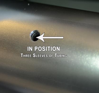
5 3. Re-Assembly from Shipping Crate (Short Pack) Carefully undo the crate packing so as not to damage the wing inside. ie: Do not cut into the box. With the wing out of the box find the control bar, battens and outer leading edge tubing assemblies. Separate the left (red) and right (green) outer leading edge assemblies. Place the wing on its back side so the down tubes/uprights are facing upwards. After removing the temporarily installed hardware from the leading edge connection and the rubber caps from the cross tube and leading edge, which is inside the fabric of the wing, put one of the removed rubber caps on the outboard leading edge to protect the sail as you slide it into place. Slide the outer leading edge tubing assemblies into the sail from the sail tip carefully and slowly. Note that the notched out end on the leading edge tubes is the side that slides into the existing leading edge tubing present inside the sail. Remove the rubber cap once the leading edge is in position. Slide the rear section of the leading edge into the front section until the hole lines up (see photos). Install bolt from the bottom up (remember the wing is inverted, *see photo below), wrap the mylar protector around the LE. After the bolt is through the leading edge put the hole in the mylar protector over the threaded bolt end and pull around and over the leading edge and bolt head and then back to the threaded end of the bolt with the other hole in the mylar protector. It does not matter which way the shield goes so long as the bolt head is shielded when finished. Now thread the nut on over the 2 ends of the mylar (top of the leading edge) and tighten snug. CAUTION: Do not over tighten or you may deform the tube. WARNING: It is possible to put the bolt in with the leading edge slid out a few inches. Many people make this mistake because they see 2 tubes when they look through the hole. When in fact both tubes belong to the outboard leading edge and the inboard leading edge will slide between these tubes making all 3 holes per side line up. Failing to line up the hole will leave the leading edge approximately 1 too long and stretch the sail beyond its design and damage the sail. Furthermore the wing will be unsafe to fly in this configuration as the leading edge would then be allowed to rotate causing a long list of problems. PLEASE BE 100% SURE the leading edges are assembled properly before flying this wing. Rev 1.1 June 1 st 2017 Page 5


6 Rev 1.1 June 1 st 2017 Page 6

7 Now install the large pivot bolt through the cross tube and channel bracket on the leading edge. Slide the cross tube onto the 3/8 bolt with the large Nylon washer between them. Note: the first side will be easy and the second side may require manipulation to line up the holes. To line up the second hole simply move the keel from side to side until the holes line up and the bolt slides through. Follow the pictures in order. First is the white nylon washer (between the bracket and cross tube), then the cross tube. On the inside of the cross tube you will have the Half moon plastic spacer, SS fender washers, then a std. small AN washer, then the castle nut and the safety pin. Note line up the hole for the safety pin so it slides in easily, then rotate the entire bolt 180 degrees to latch the safety pin. IMPORTANT: this bolt needs to be tight enough that the cross tube cannot rock back and forth. Failure to do so will cause the wing struts to be able to change angle, which WILL cause a turn in flight. Rev 1.1 June 1 st 2017 Page 7


8 4. Setup Procedure (Long Pack, Normal) 1. ASSEMBLE THE CONTROL FRAME or A-FRAME: Place the wing on the ground. Unzip the cover bag if it is in the bag. Assemble the control frame (if assembling for the first time from a short pack the control bar needs to be installed). Check the lower cable rigging to ensure that it is not tangled kinked or wrapped inside the A-frame. Caution: The down tubes can scratch the hang block when rotated into position if the hang block is not centered between them. Once in position no scratching can occur. 2. ROLL THE WING OVER Stand wing on the control frame (do not attach the lower front control frame wires at this time). Note the assembled A Frame will try to fall over and turn 90 degrees to its proper orientation. Try to limit the amount of stress put on the upper down tube connection. Rev 1.1 June 1 st 2017 Page 8


9 3. ATTACH THE FRONT FLYING WIRES Ensure that all the lower rigging is untangled first. Then make sure the hang block is slid to the aft position on the keel. This will allow extra slack in the cables and make the swan catch easy to connect. Position the forged hoop into the swan catch; install the bolt, castle nut and safety pin. 3. SPREAD WINGS PARTIALLY Carefully walk each wing out to 1/2 of it s own approximate flying position. This is the most convenient time to install the vortex generators by pushing them up through the grommets from inside the wing and then pulling them through from the top. 4. ATTACH WING STRUTS Before attaching the struts, check to make sure the cotter pin inside the lower strut fitting is properly secured. This may be the last time it is visible for preflight inspection while the wing is assembled. You must rotate the fitting to reveal the cotter pin through the sight hole. Once the wing is assembled, the cotter pin may not be visible through the sight hole. See photo on next page. Rev 1.1 June 1 st 2017 Page 9


10 Attach the upper strut fitting to the eyebolt FIRST. This eyebolt is located on the cross tube. It may be helpful to pull up some slack in the sail to have room to work inside connecting the strut. It may also help to rotate the strut and turn the eyebolt head once the pin is in to gain clearance for fingers to secure the safety ring. Once the upper struts are connected, the lower strut fittings can be connected. The front and rear cables will be extremely loose allowing the strut to be pulled several inches forward to the male fitting on the A frame. The angle of the rotating fitting must be rotated until they align. When done properly they will effortlessly slide together. 5. INSTALL THE YELLOW WING TIP STRAPS Install the wingtip sail strap (yellow) over the end of the plastic tip cap. Note: You MUST take the sail nose screws out of the metal grommet to make it possible to put the yellow webbing over the plastic tip cap. Make sure that the webbing is in the 1" inch wide shallow slot in the plastic end cap. See picture. After the webbing is over tip run a string from grommet to grommet and around the nose plate and tighten the line to create tension in the sails leading edge. You may skip this step, but the yellow strap may fall back off before opening the wing. Secure the white Velcro tabs around the leading edge. Rev 1.1 June 1 st 2017 Page 10


11 Note: After the wing is completely set up with exception of the nose battens being removed you can reinstall the sail nose screws. These screws stop the nose battens from coming off their perches during flight and also keep the wing sail secured at the tips when folded. It is only during the initial build that the yellow straps can fall off when the wing is folded. 6. POSSITION WING ON ITS NOSE Open the wing and place on its nose. Be sure that the yellow webbing does not fall off in the process. The white Velcro straps that loop around the leading edge are all that is holding the yellow webbing on until the wing is open if you did not use the temporary string though the metal grommets. Once the nose screws are installed (last step) the wing can be opened and closed without the chance of the yellow webbing falling off. NOTE: the nose screws will not line back up to re-secure the sail until the wing is completely built. In order to get the wing on its nose, it is best to have 3 people. One on each wing tip to lift up to head height, and one on the nose. The 2 people on the tips should lift the wing and spread it open while watching the yellow tip straps to ensure they are not twisted, fully seated and not falling off. Once the wing is spread open with the tips at eye level the yellow straps will be snug, the wing will be nearly balanced and the person standing at the nose can take the wing and slowly lower it to the ground. Once the wing is installed on the REVO we do not recommend removing the wing for transport. Beyond the initial build, there should never be a need for assistance to fold and transport the wing. Set up and break down of the RIVAL S wing on the REVO is a 1 person job even if you remove the wing from the REVO, so long as there is no need to short pack the wing again. Rev 1.1 June 1 st 2017 Page 11

12 7. INSERT ALL UPPER BATTENS Install all of the upper battens; battens with white front ends on the right side, black on the left. Insert the battens from root to tip with gentle pressure, moving the sail s trailing edge up or down as necessary to help the front of the battens up over the cross tube and leading edge. Battens 12 and 13 may get stuck. DO NOT FORCE or you can tear the batten pocket (sail). Pushing the cross tube down at the hinge joint (unzip zipper and push down with your foot) may allow the batten to slide in easily. If it doesn t, find the tip of the batten by feeling inside the wing with your hand and lift it from inside the wing up and over the cross tube to help it slide all of the way in. The wing can be tilted to allow the leading edge to lay flat on the floor to be able to easily access all of the batten pockets. An alternative set up method would be to install the wing on the trike with a short bungee loosely securing the haul back cable to the latch before installing the battens. Failure to temporarily secure the haul back if the wing does not remain on its nose can result in the wing to collapse. Secure all batten strings before tensioning the sail. 8. HOOK UP the haul back cable If using the first method with the wing on its nose, use a step ladder placed inside the A frame to reach the haul back cable. Remember, once the wing is on the REVO the wing will be level when you haul it back to fold and unfold the wing and no ladder will be needed. Pull the cable all the way back, until you can latch the cable shackle into the spring catch. Make sure the wing tip yellow webbing is completely in the 1 slot on the wing tip cap before tightening the wing with the haul-back cable. Rev 1.1 June 1 st 2017 Page 12
.")

13 7. LOCATE SPROGS INTO POSITION Rotate the four sprogs out to center of the transversal batten. Now put the Velcro loop around the end of the sprogs. Leave Velcro loops slightly loose (approximately 1/2 gap). Not having the lower battens in will allow you to reach into the sail to get to the sprogs. If you cannot reach the inboard sprog, go in through the strut zipper and swing the sprog out as far as possible, then pull it out from the trailing edge while lifting up on the trailing to get the sprog under the transverse batten. Rev 1.1 June 1 st 2017 Page 13
 of equal length.")
14 8. UNDER SURFACE BATTENS Install the under surface battens from longest to shortest. Make sure the back ends are inserted back into the slot at the rear. The spoon shape should be spoon up or convex side down. NOTE: The 3 rd longest set of battens have 2 sets (4 battens) of equal length. It is important to realize that one set is ½ thick and the other set is 3/8 thick. These battens can accidentally fit into the wrong batten pockets since they are the same length. The ½ battens start at the root and there are 3 per side, then the 3/8 battens start at the 100% double surface section of the sail and go all the way to the tip. 9. TIP BATTENS The sprogs MUST be in place to make tip batten tension adjustments. Failure to do so will give a false tension and cause the struts to be adjusted too short. Install the upper tip battens in the upper leading edge hook. Fold the tip batten by pulling back the spring loaded slide by compressing the spring and hinging the strut. The open end of the strut goes on the top hook and the plastic fitting goes inside the pocket sewn into the corner of the upper surface. The tension of these tip battens is fairly critical for tuning purposes. They should be just snug when straitened. The undersurface tip battens slide into the open pocket sewn into the undersurface fabric and then slid onto the leading edge hook. The back of the lower tip batten with the bungee cord loop. Secure all bungee cord loops at this time. This includes the tip battens and the 100% double surface sections of the wing a that has provided bungees. NOTE: Be sure to place the lower tip batten BETWEEN the bungees spanning from upper to lower surface, then pull the bungee on the top of the upper surface to the batten tip and pull the bungee below the bottom surface to the same batten tip. When done properly this closes the trailing edge together with no gap. The bungees will hold the undersurface sail tension as well as hold the upper and lower surfaces together. Rev 1.1 June 1 st 2017 Page 14
 and then lift the nose of the wing until the hang block hole lines up with the")


15 The wing is now ready to install on the trike carriage. Simply drive the trike carriage nose wheel over the control bar with the mast down (see REVO POH manual) and then lift the nose of the wing until the hang block hole lines up with the mast s hang bolt hole. The hang bolt must go through the rear hole of the hang block. Once the wing is connected to the REVO, allow the trike base to roll backwards over the control bar again and the keel will meet the back side of the mast. This will in effect lock the wing in a position to lift it as well as stabilize the wing and allow the front of the nose area to be within an easy reach. NOTE: If your wing is equipped with the optional electric trim system. This is a good time while the center battens are out to install the linear actuator. The linear actuator is secured at the top nose channel bracket with a ¼ Clevis pin and safety ring as shown in the pictures below. On the top of the keel tube of the wing near the nose where the linear actuator will sit, the keel is protected by a strip of sticky industrial Velcro (soft side).. Rev 1.1 June 1 st 2017 Page 15

 that sits above the top nose")
16 POSITION THE NOSE BATTEN AND NOSE CONE Put the nose ribs on the 1/4 stud located front top of keel tube. With the nose cone in hand start with the two top Velcro tabs and gently pull the nose cone down and around the nose plate to connect the two bottom Velcro tabs on the nose cone to its corresponding Velcro sewn on the under surface below the keel. CAUTION: the nose cone is required for flying the RIVAL S 11. CHECK AND CONNECT THE ELECTRIC TRIM SYSTEM IF APPLICABLE The electric trim system consists of a linear electrical actuator with a 4 inch stroke, (3 on earlier models) that sits above the top nose plate. It connects its stroke arm to a machined cylindrical fitting using a ¼ pin. This fitting is tapped to accept threaded ¼ x 28 male studs with crimped on cable assembly that run to the slider plate directly behind the hang block via (6) AN-4 nuts. It is critical that the trim cables are properly routed. The correct routing of the cables is through the cross tube strap (thin black strap) and outside the keel strap (thick white strap). The linear actuator can be removed easily by removing the two pins and undoing the electrical connector. The non lock nuts are used in front and behind the slider plates and then tightened against the plates by using 2 wrenches after proper length has been established. The slider plates should be just or almost touching the aft limit stop bolt that is in the keel when the trim motor is in full slow (completely extended). You can leave approximately 1/8 gap to allow for stretch in the system. Once the nuts are tight hold the nut in front of the slider plate and thread on a locking nut to the trim cable. WARNING: Removal of the linear actuator is necessary for folding the wing whether attached to the trike carriage or off the trike carriage or for bagging the wing in its bag. Otherwise the cross tube hinge will impact the linear actuator when the wing is folded and cause damage. Also note that after removing the linear actuator from the wing, the cylindrical barrel that is attached to the cables should be routed through the cross-tube hinge cover assembly that has a black strap loosely tying the cross-tube to the keel. If this is not done you will feel some resistance to folding the wing back. Do not force anything. Take the time to figure things out and where the hang up is coming from if resistance is felt. If something seems to be Rev 1.1 June 1 st 2017 Page 16


17 binding and you cannot locate the problem, be patient and ask for support from the dealer or factory. WARNING: The electric trim linear actuator MUST be removed when folding the wing. This is done by taking the pin out of the actuator s main body, removing the machined round cylindrical barrel that has two cables screwed into it and unplugging the electric. There are no short cuts around this step without causing damage. CAUTION: Make sure all zippers are closed after you pre-flight your wing and before you fly. Rev 1.1 June 1 st 2017 Page 17
18 5. Preflight Procedure A thorough preflight procedure is mandatory with all aircraft. The best technique is a circular walk around. Start at one location, the nose, and check each assembly point available for inspection. Sight along both leading edges, checking for similar curves. Walk towards the tip, feeling for dents in the leading edge tube. Pause at the wing bolts and look into the sail through the zipper inspection access. Check side struts fittings and safety rings. Continue to the tip and check the sail tip area for proper seating on the leading edge tube, and sail integrity. Verify that the sprog tubes are positioned correctly and Velcro straps are in place. Insure that the tip battens are properly seated on the leading edge hooks, and that the tension is set just snug. Walk to the keel, checking each of the battens to ensure that they are properly secured. Check the haul back cable catch connection. Repeat first half inspection as you work your way back around the nose. Check the swan catch at the nose. Check the nose cone for secure attachment. Check all the lower cable rigging for proper routing about the control frame. Check that the control frame uprights are straight and that the set up bolt is correctly assembled with castle nut and safety ring through the base bar and forked end fitting Check the cross tube center bolt/plates to insure that they are properly attached. Check the hang block and all bolts in the block. Make sure you zip up the center zipper after inspection. Flying the wing with the center zipper open (or any zipper) will result in loss of lift and pitch stability and cause dangerous flight handling!! Generally site the entire wing for symmetry. If you see something that does not look right, stop and investigate. 6. Fold Down Procedure It is very important to note that the RIVAL S wing does NOT fold all of the way back (wing tips together) with its wing struts attached. The wing may be folded and trailered, but the tips will remain no less than 4 feet apart. This wing is designed to work with the REVO trike dolly for transport in an enclosed trailer. The wing can be folded all of the way back to put in its bag once the wing struts are removed after removing the wing from the trike carriage. Always fold the wings together symmetrically, bringing both leading edges back together at the same time. An alternative Rev 1.1 June 1 st 2017 Page 18
19 to having someone help bringing in both leading edges at once, is to bring in one a bit, then the other a bit more, in three to four incremental steps. If you find resistance folding in the wings, check that the haul back cable is free to run forward through the cable hole center of the sail. To fold the wing back by yourself with the REVO on its trike dolly, once it is time to fold the wing back, (see photo on next page) simply attach a 20 rope or tie down strap to the wing tip strap handles, and pull the wing tips back by walking backwards away from the back of the trike with both ropes in one hand. The wing is very level in this position so the wing tips will tend to stay where you leave them WARNING: Do not fold the wing with optional electric trim linear actuator attached above the keel tube. This can cause damage. WARNING: Do NOT attempt to fold the wing tips all the way together with the wing struts still installed. To fold down your RIVAL S wing, just follow the reverse set up procedure steps as described in the previous section. Included below are a few guidelines to follow which will save you time and prevent wear areas on your sail. So tip battens are removed first, then the sprogs, next comes the undersurface battens, and then the haul back etc. REMOVE LINEAR ACTUATOR 1) Take the Dacron nose cone off and open the bottom zipper. 2) Pull up the nose battens from their perches on top of the nose plate and take them out towards the front. This should make it easy to put your hands in through the front and from the bottom 3) Put your hands in and take the safety ring off for the linear actuator Clevis pin attaching it to the top nose channel and on the cylindrical fitting (attached to cables) in front part of linear actuator (movable shaft side) 4) Disconnect the linear actuator electrical connection and pull the linear actuator out of the wing leaving the cables with the machined cylindrical barrel inside 5) Take the machined cylindrical barrel and cables and guide them back through the black loop that keeps the cross-tube hinge and wing keel tube together. To do this you may have to gently lift the cross-tube hinge up by hand just a bit and slide the cables back. See pictures on FOLDING THE SAIL Once the frame is folded with all of the battens out the wing sail will naturally fall between the keel and the leading edges. The sail must be pulled up and routed outside of the leading edges so that there is little fabric between the leading edges and the keel. Once the sail is pulled to the outside of the wing, the sail can be rolled up tightly and then tucked inside the leading edge. The important thing is to get the sail neatly stowed inside the leading edge pocket as shown in the photo below. Rev 1.1 June 1 st 2017 Page 19

20 REVO dolly cart shown ATTACHING SAIL TIES Fasten the first tie just aft of the rear cable. By keeping the keel tube outside of the tie, it will make it easier to organize the control bar in this area after the wing is flipped over. The forward tie is located splitting the distance between the control frame apex and nose plate. Pull the leading edge pocket up over the top of the wing so the top of the LE Mylar pocket is touching and/or overlapped. The third sail tie goes about 2 feet inboard from the leading edge tips. 7. About Operating RIVAL S/X Wing Taxiing the RIVAL S and RIVAL X with the the wing level (control bar straight) while in a crosswind will require excessive strength. Most trike wings require the upwind wingtip to be lowered, however due to the high amount of anhedral designed into the RIVAL S, and X it requires the up wind wing to be held close to parallel to the horizon (still slightly down). This will appear to look as if the wing is being banked AWAY from the wind contrary to the technique used with most other wings. On takeoff the wing should banked in this attitude and be leveled just before the bar is pushed forward to lift off. Using this technique will eliminate any additional workload on the ground while taxiing in the wind. Once the trike lifts off the ground the force required on the control bar will be eliminated entirely and only minimal control force will be needed to bank the wing. Rev 1.1 June 1 st 2017 Page 20
21 The RIVAL S wing flies between 55 and 100 MPH hands off trim with the optional electric trim and the RIVAL X flies MPH with the optional electric trim. This is where the trim limits are set on the keel. Adjust the trike on the keel to fly the speed of your choosing. It is recommended that you trim the wing between MPH if you are using a fixed hang point. In order to use a fixed hang point (no electric trim) a collar is clamped aft of the hang block to stop the hang block from sliding back beyond this point. There is no need to put a collar in front of the hang block as it will slide back to the clamp collar in flight and remain there. A good starting point on the keel will be 75% back between the fast and slow stops. Due to variations in tuning there is no exact hang point for a particular speed. At gross load the RIVAL S/X may stall at slightly higher than published speeds based on the tuning of the wing (looser than middle hole on hall back adjustment or less than 3/8 shims in both wings, looser batten tension than factory set). The takeoff ground roll on pavement for the RIVAL S/X wing varies greatly based on many factors such as weight, HP, atmospheric conditions and tuning. (see the REVO POH for performance figures on the REVO carriage). Taking off in grass, downwind, uphill, or with a crosswind especially coming from over tree tops will further increase the takeoff distance well beyond many pilot s guestimates, so be sure you have more than enough runway. It is important to get to a safe climb out speed before leaving ground effect which is around a bar position no less than 9 from full bar forward. For REVO and REVOLT trike carriages please see the REVO or REVOLT POH. It is advised that as speed builds up the pilot leans forward out of the seat with their back straight in order to keep a bend in his/her arms (no locked elbows). Push the bar forward ALL of the way to touch the compression strut of the trike carriage if equipped with one PRIOR to lift off speed and then wait for the nose to lift as speed increases. As the nose wheel lifts, pull back and relax the control bar to a position of no less than 9 from the compression strut ideally before the trike reaches from the ground. Never leave ground effect with the control bar at or less than 9 from the compression strut. These high angle of attack maneuvers are safe at or below and above 1000 AGL giving the pilot enough time to recover from an inadvertent stall. Stalling the RIVAL S/X wings at or below 12 should provide a very soft landing. Stalling from should be avoided, but will not cause damage unless the bar is pulled in during the stall. WARNING: Leaving the bar pushed out after the trike takes off can cause a possible stall. Please note RIVAL S wings manufactured before July 2014 did NOT include an extra set of NOVICE #1 battens. These wings came standard with the advanced #1 battens only which were NOT labeled. Please contact Evolution Aircraft Inc. to order a pair of novice battens if desired. Roll control on the RIVAL S wing should be done with extremely small horizontal bar movement when not using the special NOVICE battens in the #1 batten pocket. We recommend flying the RIVAL S with the novice #1 battens in place even if you are not a novice until familiar with the flying characteristics of the RIVAL S. When using the ADVANCED #1 battens we recommend holding pressure to turn. This works much more precisely than bumping the controls from side to side. It is very common for even advanced pilots to over control The RIVAL S during the first Rev 1.1 June 1 st 2017 Page 21
22 minutes of flight on the new wing. We suggest flying the RIVAL S in calm conditions and making an effort to move the control bar no more than 1 from side to side until the pilot has the feel of the wing and is comfortable with the responsiveness. If able to get transition training from an experienced instructor we highly recommend it. The controls are not difficult to use in the advanced mode as much as they are extremely light and responsive compared to the vast majority of trike wings on the market today. Flying in the advanced mode simply allows movements to be small enough and light enough to reduce fatigue so long as the pilot does not over-control the wing which creates perpetual effort to continue flight. Moving the bar 1 and holding pressure for 4 seconds works much better than moving the bar 4 for 1 second. The RIVAL S will want to continue rolling in the direction the pilot initiated the bank. Once the trike rolls to the desired bank angle PUSH THE BAR STRAIGHT FORWARD. This will coordinate the turn and stop the trike from continuing to roll into the turn. If the bar is pushed forward too abruptly, the trike will start leveling back out. Pilots that give opposite roll input (move the control bar to the right to stop the trike from banking too steeply to the right) will cause the wing to Dutch roll which will cause additional control force needed on the control bar. This technique is highly inefficient and will cause the RIVAL S to slip sideways through the air. Understanding how to coordinate turns with the RIVAL S is one of the keys to mastering this wings capabilities. As your skills with the RIVAL S advance you can make fast turns using the J maneuver and experience over 75 degrees of roll rate per second. This technique should be learned from an experienced instructor. The RIVAL S has the capability to radically bank faster than most trike pilots will ever want, small soft inputs result in smooth controlled turns. Radical jerks to the control bar will result in radical bank angles. However fast roll rate is one reason the RIVAL S can be flown quite effortlessly in high turbulence with minimal effort. The RIVAL X can be flown with much larger side to side bar movements and will tend to stop rolling as soon as bar pressure is released. When rolling quickly it is necessary to push the bar forward to coordinate the turn. Slow banks will tend not to require such coordinating of the turn. The safe operation of this or any trike wing ultimately rests with the pilot in command. Because the responsibility of flying and maintaining the wing rests entirely with you, the risk of damage or injury you may cause to others and to yourself also rests entirely with you. We believe that in order to safely participate and practice the sport of flying, you must maturely accept responsibility for yourself and others. We recommend to fly conservatively, and avail yourself of all safety equipment (i.e.; parachute, strobes, etc.) appropriate to the conditions and terrain you fly in. No wing on the market is totally infallible. It is entirely possible to push any aircraft beyond its limitations and damage or even break a wing. Very strong weather conditions may also cause structural failure. WARNING: Aerobatic maneuvers, pitch angles beyond 30 degrees nose up or down, bank angles exceeding 60 degrees, aggressive stalls, and spins are maneuvers that should never be attempted under any circumstance. Rev 1.1 June 1 st 2017 Page 22
23 WARNING: Do not exceed (86 MPH RIVAL S) and (74 MPH on the RIVAL X)I n rough air or make large or fast control bar movements above these speeds. If you encounter turbulence at high speed, lift off the throttle immediately, then reduce airspeed by pushing the bar forward and then relieve the bar pressure by adjusting the electric trim if equipped. WARNING: RIVAL S Vne NEVER EXCEED SPEED 115 MPH RIVAL X Vne NEVER EXCEED SPEED 105 MPH RIVAL S Va MAXIMUM MANEUVERING SPEED 86MPH RIVAL X Va MAXIMUM MANEUVERING SPEED 74MPH Structural damage is possible if these limitations are exceeded. Respect these limitations. 8. Flight Limitations Operations and limitation for the RIVAL S/X wing on the Light Sport Aircraft such as the Revo or REVOLT is available in the POH manual. The wing performance placard bearing test flight information and operating limits is located on the wing s left cross tubes. Special care should be taken to note the operating limitations, which are clearly stated on the flight operation placard. As with any wing, special care should be taken to note the operating limitations, which have been ascertained by careful testing. Flight operations should not exceed those laid down in the operating limits specified within this manual. No wing is totally infallible; there are inherent risks involved in flying a trike wing. It is quite possible to fly the RIVAL S wing beyond its operating limits using deliberate flying skills. The responsibility for safety rests ultimately with the pilot alone who must decide whether the wing they are about to fly has been properly maintained, and is in air worthy condition. FLIGHT OPERATIONS: Should be limited to non-aerobatics maneuvers -- those in which the pitch angle will not exceed either 30 degrees nose up or nose down of the horizon and in which the bank will not exceed 60 degrees. WARNING: The owner and operator must understand that due to the inherent risk involved in flying such a unique vehicle, no warranty is made or implied of any kind against accidents, bodily injury, or death. Operations such as aerobatics maneuvers or erratic pilot technique may Rev 1.1 June 1 st 2017 Page 23
24 ultimately produce equipment failure and are strongly discouraged. NEVER FLY FASTER THAN VNE: To verify the speeds you are achieving, you should fly with an accurate airspeed indicator. During certification testing, test pilots found that it would be possible to exceed VNE during smooth acceleration. The most typical cause of exceeding VNE is rapid acceleration performing aerobatics maneuvers and steep spiral dives. Rev 1.1 June 1 st 2017 Page
25 9. Wing Tuning When a wing is new and from time to time it may be necessary to tune the wing to get rid of small turns etc. Flex-wings unlike rigid wings stretch over time or with load and this can happen unevenly over time and turns can develop. When folding, packing the wing, the operator should note how things were so when the wing is unfolded to get it in its flying format, all things are roughly put back in the same scheme as before. Thus it is invaluable for the operator to take some pictures of different areas at some point when the wing is flying well and keep them handy in case the operator needs to refer back to these pictures for anything. Tuning of the wing should be done in calm conditions and only one thing should be changed, logged and a test flight be performed to note its proper effect. This section is by no means a complete guide on tuning. The idea is to give guidance on the most basic tuning for the most common problems. If the wing develops a severe turn all of a sudden or is divergent, the operator needs to think about what happened or changed last? If there was a hard landing or crash, was there a thorough inspection done of the tubing for straightness? What about a sail inspection? After a crash, the sail of the wing could stretch so unevenly that it may not be possible to bring the wing back in tune easily at all without changing to a new sail or getting it back to the manufacturer for testing and tuning. If any adjustments are made on your wing, we recommend that they be noted in your Maintenance Log or aircraft logbook. It is then easy to go back and trace occasional problems. Please bear in mind that certain adjustments, like the cross tube sweep setting, are very critical and often create trade-offs in handling, performance, or --more seriously-- safety. Never make more than one change at a time. This is a basic rule in test flying, which allows you to keep track of the progress made. Trouble shooting: the most common need for tuning is from a turn. It is advised that if a turn develops that you trace back ANY asymmetry that was previously done for tuning purposes. There is nothing worse than tuning a wing that is already tuned and the second tuning job is done to compensate for the first tuning. Instead, it is usually best to set the wing back to stock. In order to do this there are several things that must be checked: 1) battens are set to the batten chart 2) leading edge shims are equal (3/8 shims are standard and recommended on both sides) 3) tip twist. The Factory setting is 40 degrees relative to the keel 4) inboard sprog angle is 10 degrees relative to the keel 5) outboard sprog angle is 20 degrees to the keel 6) webbing straps or internal bridging fully lapped Velcro 7) keel strap fully lapped Velcro 8) batten string tension snug and consistent, especially on both sides of wing 9) trim tab on wheel pant straight Rev 1.1 June 1 st 2017 Page 25
26 Turn in Wing Many factors such as asymmetrical wheel pants or asymmetrical windscreen from poor mounting or a twisted mast from wear and tear or a leading edge strike can cause the trike to have a turn. The thrust line can be mis-adjusted as well causing an unwanted turn in flight. The wing may not be the source of the problem. It is always best to fix the source of the problem and not tune the wing to fix the problem if the source of the problem is not in the wing. Having said that, it may be difficult for an end user to find the source of the problem. If the trike has been rebuilt, had a roll over or the control bar does not appear to be straight (perpendicular to the main trike carriage keel) these factors should be considered before making adjustments to the wing. When making adjustments, if there is no result from the tuning, DO NOT leave the adjustment in the wing if it is different than the factory setting. Return the wing to the factory setting when no result is achieved from making a change. 1) We have found the most effective way to tune out a turn specifically on a RIVAL S wing is to open the webbing strap at the upper wing strut connection point zipper by ½ at a time with a maximum of 2 of Velcro showing from fully lapped (closed). Although this is very effective the next webbing strap in towards the root can be opened in the same manner. The wing that raises during flight is the side you open the webbing strap on. This may seem contradictory to what might be expected from this adjustment. Again this is a specific result to the RIVAL S. For the RIVAL X batten tension is the best way to tune for a turn. Tighten the string tension on the low wing all the way down the wing or loosen the strigns on the high wing. It is advised to seach for the tightest strings on the high wing and loosen them first and find the loosest strings on the low wing and tighten them first. 2) If step 1 does not eliminate the turn entirely, we suggest the trim tab on the REVO be adjusted. To eliminate a left turn, bend the trim tab out on the left wheel pant. This will work especially well for a high speed left turn. If the REVO is equipped with an electric roll trim option simply press and hold the trim until the trim tab eliminates the turn during flight. For REVOLT trikes batten 5&6 can have the camber increased on the low wing and 5&6 camber decreased on the high wing. It is recommended that the front curve match the batten template and then the straight tail of the batten stray away and end up either up to 2 above or below the end of the batten end point on the template. 3) As a last resource, adding reflex to the descending wing can also be done. When adding camber only battens 5&6 should be adjusted as they have little effect on the pitch stability of the wing. However we have found best handling to come from a symmetrical airfoil. Please consult the manufacturer before bending battens as this can make the wing unsafe to fly in some cases if the battens are bent too much. A good rule of thumb is NOT to raise the high point of the camber more than ¾ and if reflexing the batten, not to make the tail of the batten 1 higher than the standard profile on the batten chart. If the terms above are unfamiliar or unclear DO NOT attempt to alter the batten profile yourself. Find someone with experience to help. Rev 1.1 June 1 st 2017 Page 26

27 4) Although we have found twisting the tip caps or lengthening or shortening the tip cap out with different sized shims to be ineffective, there are always exceptions where this may be needed. However we recommend you contact Evolution Aircraft Inc. if you have not resolved an unwanted turn by step #4 * To modify leading edge tension, slip the tip webbing off the plastic end cap and slide the sail forward. You will need to remove the leading edge screws under the nose cone and fold the wing slightly with the battens removed to get the yellow strap off. You will see that between the plastic end cap and the leading edge tube there is a piece of tubing cut to 1/8 up to 1/2 long, these are shims. These are what change the LE tension. TO remove the end cap, back out BOTH Phillips head screws 3/8 then hit the screw driver in to make the screws go flush. Hitting one screw should make both go flush. DO NOT ATTEMPT THIS WITH ONE SCREW STILL TIGHT. The plastic end cap can now rotate freely and be pulled out to swap shims. Replace the plastic end cap and the yellow tip webbing. Remember the angle of the tip cap must be re set before tightening the 2 screws back up. There are marks on the leading edge or use a protractor to set them at 40 degrees to the keel. NOTE: Make sure to mark the stock 40 degree position on the metal leading edge. And also mark where the rotation was before it was removed so it can be set back to where it was. The rotation of these caps is very important! Rev 1.1 June 1 st 2017 Page 27
28 The Wing Flies Too Slow 1) If equipped with electric trim ensure the trim system is operating to full fast position with the front of the HB touching the forward limit through bolt in the keel. If collars are used for a fixed trim speed setting, move the collars forward ½ at a time. 2) Tighten the haul back cable. There are 3 holes to choose from for the adjustment pin which is under the neoprene cover near the haul back handle. Simply unhook the haul back, adjust the cable length, and retention the wing. 3) Loosen the internal webbing straps 1 at the wing strut zipper on both sides. Possibly loosen up the next inboard webbing strap up 1 if needed. These webbing straps very much control the speed of the RIVAL S as well as having the ability to induce a turn. 4) Loosen the keel strap. Loosen it ½ at a time not to exceed 1 of unlapped Velcro 5) Twist the tip caps down (increase the AOA) adjust these in small increments of 5 degrees. Do not twist below 30 degrees relative to the keel. The Wing is Divergent (flies with unlimited or increasing speed) 1) Tighten all webbing straps to fully lapped (stock setting) 2) Loosen the haul back cable 3) Tighten keel strap to fully lapped (stock setting) 4) Twist tips up to 40 degrees relative to the keel (stock setting) 5) Reflex battens 13 and possibly batten 12 and 11 as well. This step should not be needed but will effectively increase the pitch stability of the RIVAL S Contact Evolution Aircraft if you need further detail 10. Transportation and Storage The RIVAL S/X wing bag is NOT waterproof. We do offer a waterproof bag that goes on the outside of the standard wing bag. Avoid hard spots pressing on the wing during transportation or storage and have as many supports as possible; we recommend using a well padded three-point support system, with less than four feet of unsupported wing extending off either end. Use flat tie down straps, at least 1 width rather than elastic or rope to secure the wing, and tie both ends of the wing to a support or down to the ends of the vehicle in order to prevent the wing from flexing. Take care to not over tighten the wing tie- downs, as this can crimp your Mylar leading edges. A good technique is to squeeze and compress the wing s Mylar, sail, and leading edges into a snug bundle as it gets tied down, rather than using the wing tie-downs to compress the wing within the bag. It is preferable to keep the wing dry. Definitely ensure that it is dry before storing for longer than just overnight. Any contact with salt water, of course, requires immediate rinsing with fresh water to prevent corrosion to hardware, rigging and tubes. Rev 1.1 June 1 st 2017 Page 28
29 We highly recommend using the REVO trike dolly on REVOs to transport the RIVAL S/X wings on the trike in an enclosed trailer. Instructions for using the Dolly and folding the wing on the trike can be found in the Dolly manual. Also the website provides videos on the wing page for transport with the dolly. 11. Regular Maintenance Schedule The RIVAL S/X wings will require very little in the way of maintenance if you care for it properly in your day-to-day use. Following are some general points to follow in maintaining your new wing which will help ensure the safety of your flying and the performance retention of your wing; we suggest you follow this maintenance schedule faithfully -- your ongoing care will pay off in the future. A note on use of silicone spray: This lubricant is useful in that it can minimize friction on zipper pulls. Care must be exhibited, however, in that if you do not wipe off excessive silicon application, the fluid will act essentially as a dust and dirt magnet. Due in particular to the problems associated with silicon attracting foreign material, we recommend against the practice of using silicon on your wing s battens. Clean, dry battens all by themselves are the best ways to prolong the life of the high wear area of the sail batten pockets. Probably the best way to prolong those batten pockets under adverse conditions is to wipe off the battens with a clean dry cloth prior to each insertion. 12. Sail Maintenance If you must wash the sail, wash it with a light detergent only. Better still; wipe the sail down frequently with a soft, damp cloth keeping detergent washing to a minimum. Because of the acids in their system bug grime should be cleaned immediately to prevent long- term deterioration of the sail. To renew the luster of Dacron, you can use the product called Sail Bright available from marine hardware stores. Use as directed. Apply sail repair tape to small (less than 1 ) holes in sail. This will prevent fraying on the edges where the opening is located. Any small rips located at stress points (i.e. the trailing edge or critical seams) should be professionally repaired to insure that the structural integrity of the unit is not compromised. Any rip in the trailing edge seam area is cause for grounding the wing until repaired. CAUTION: Sun and weather cause more deterioration than hours of flying. Keep your wing covered when not in use. Wing covers are available. 13. Monthly Inspection Check Nose battens against the airfoil maintenance blueprint if any turns or undesirable handling characteristics develop. Rev 1.1 June 1 st 2017 Page 29
30 Inspect all batten tensioning cords Lubricate the zippers on the sail and cover bag. Rev 1.1 June 1 st 2017 Page 30
31 14. Twice Yearly Inspection Remove the cross tube center junction scuff pad to inspect all cross tube support cable components: tangs, pins, nuts, bolts, cross tube and cable itself. Tighten nuts if loose. Check all tubing, especially the control bar frame, for possible damage, which could occur during, set up, fold down, or transportation. Closely inspect the sail mounting grommets and webbing at the tips. Inspect the sprog cable for wear and/or undue stretch. Inspect all rigging and components. Replace any worn, bent or corroded bolts or locknuts connecting two moving parts together: cross tube plate junction bolt, cross tube clamp bolt, etc. A professional sail maker should mend critical sail tears. 15. Annual Inspection The only way to thoroughly and completely inspect all of the components of your wing is to completely remove the sail from the frame, to allow visual and physical access to everything. Even if yours is the best-kept RIVAL S wing, you should have the sail removed for a complete inspection at least once every three (3) years or 500 hours whichever comes first and then every 250 hours or 2 years thereafter. This should be done by an authorized service center or a qualified mechanic. With the sail off the airframe, you can more thoroughly perform all of the inspection points listed for the six-month inspection. Additionally, you should inspect inside the tubes for corrosion. If discoloration indicating that corrosion is present, you will need to arrest this process immediately. We have tested and approved boiled linseed oil (commonly found in most hardware stores) as an effective coating/film to apply on the inside wall surface of the tubes. Clean the tubes first, allow to dry and then apply the linseed oil. Inspect the entire inner sail body, and in particular examine the batten pockets for wear points, especially at their stops at the front of each pocket. Rev 1.1 June 1 st 2017 Page 31
32 WING INSPECTION Mark P for pass or F fail at each line Cable System RIVAL S/X Wing Manual The cables must be checked for broken/kinked wires (frays), corrosion, niko and thimble condition. If any defect is observed, no matter how small, the cable in question MUST BE REPLACED. It is recommended that the entire cable system be replaced once every eight (5) years or 500 hours irrespective of service conditions except backup cabling. Cables can be obtained from the wing manufacturer or assembled by a repair station with proper expertise and equipment. Alternately they can be assembled to custom lengths and thicknesses by aviation supply stores such as Aircraft Spruce Cables and Cable Maintenance The cables which support the wing s airframe are critical components of the wing s structure, and must be maintained in an air worthy condition. It is a general practice in the design of aircraft structures to design to an ultimate strength of 1.5 times the highest expected load in normal service. Cables, like other structural components on the wing, are typically designed with a structural safety factor of only about 50% above the expected maximum load. No significant loss in cable strength can be tolerated. A cable with even a single broken strand must be replaced before the wing is flown again. A cable which has been bent sharply enough to have taken a permanent set must also be replaced immediately. Some degree of fatigue due to repeated bending of cables is almost unavoidable in an aircraft that is assembled and disassembled with every flight. Sail Check-Up Check the sail surface and seams there should be no cuts, ruptures, threadbare holes and torn seams on the sail. Any torn seams should be re-stitched. Cuts and ruptures on the leading edge and under surface of the sail that are not longer than 1.25 (30 mm) can be patched up with selfadhesive Dacron sail appropriately. The Dacron must be of a weight of not less than 100 g/m. Larger cuts and ruptures are to be repaired by stitching on a reinforcing piece of the same fabric (stitched along the edges). Any rupture shorter than 8 can be repaired in this manner, but more complicated repairs and all cuts near the trailing edge should be carried out in an approved and authorized manner or via the manufacturer of the aircraft. Rev 1.1 June 1 st 2017 Page 32
33 Sail Strength An annual Bettsometer test with a inch diameter needle (1 to 1.2 mm), with wing sails fitted and tensioned for flight is to be conducted Upper & lower surface: 3 lbs or 1360 gm. There are test panels sewn on the top surface of our wings where this test can be conducted Stitches: 3 lbs or 1360 gm using a inch (1 to 1.2 mm) diameter hook, pull upwards. Besides the annual check there are several criteria for testing of sails dependent on the conditions that the sail fabric is exposed to. The pilot/operator of the aircraft is responsible for determining the level of exposure that the sail experiences. UV is the killer of sailcloth and is to be avoided as much as possible. Annual testing is adequate except in cases where a more harsh and exposed environment warrants more frequent testing. In such cases every 200 operating hours regardless of time (annual or not), the Bettsometer testing should be conducted to see if sail and stitch passes. Keep an eye on the sail grommets/eyelets and all areas of the sail that are subject to extra stress, especially the wing keel section, the nose section of leading edge and the outer tip section of leading edge. There are test panels sewn on the top surface of our wings and if there is any question or doubt, these panels can be cut out and sent to the factory for testing strength of the sail material for airworthiness. Tubing and Structure Check all nuts, bolts, safety pins, and hardware on the wing. Check all tubing visually for corrosion, straightness, dings cracks etc. If there is absolutely any doubt, check the tubing as described below in full tubing inspection. Check all brackets and connections in the structure for cracks etc. Full tubing inspection (at 500 hours since new and then every 250 hours thereafter) At 500 hours and then every 250 hours thereafter or if it is known that the wing has had hard landing or the trike has flipped over due to adverse weather conditions when outside, it is imperative that tubing and brackets be inspected fully with sail-off in the following manner: To check the condition of the wing tubes the sail should be removed from the wing frame by unlocking all the fasteners that secures outside cabling and/or struts to the wing structure, removing the hang block plates or hang block as applicable so the keel pocket can slide through the keel tube, close the wing in so its in packed position and snaking the fabric off the structure. Then the tubes should be detached at the joints. The tubes are to be inspected visually. When there is suspicion of damage, the points in question should be inspected using a magnifying glass of (5-10) X magnification. A straight edge may be used on the tubing to ascertain straightness. There should be no trace of corrosion, cracks, bends or dents Take all battens out, loosen all fasteners, struts, cabling and cross tube and leading edge junction, hardware, straps and hang block elements that hinder the sail from coming off the tube structure Rev 1.1 June 1 st 2017 Page 33

34 After closing the wing, the frame can now be snaked out through the nose of the sail. Fasteners Check all fasteners (bolts, screws, rollers, nuts, splint pins etc.) for corrosion. Any corroded/rusted fasteners should be replaced. Bolts should not be worn and/or bent. Key bolts should be checked most thoroughly for cracks between the head and the bolt body. These are the bolts at the control bar side and bottom joints, the cross tube tensioning cable attach point and there are cable attachment point on the keel tube. If any cracks are observed REPLACE IMMEDIATELY! Battens and Batten Tips and Batten Cords The batten profiles should be checked if the user complains of a turn against the template and the bends should be adjusted if necessary to the template. Check all the plastic batten heads and tails and replace if necessary. Batten templates can be ordered from the manufacturer. Only those battens that are known to be bent beyond the original template for wing tuning purposes and logged in aircraft maintenance log as such should be allowed to deviate from the manufacturer batten template. If any of the batten tightening cords are torn or heavily worn they must be replaced. The cord is 400 pounds spear fishing line available at many scuba shops or can be ordered from the factory. Any batten trailing edge tips that are worn should be replaced if applicable and can be ordered from the factory WARNING: WHEN REPLACING PARTS OR INSPECTING, NEVER REUSE A NYLOCK Rev 1.1 June 1 st 2017 Page 34
Falcon 3 145, 170, 195 and Tandem Owner / Service Manual
 Falcon 3 145, 170, 195 and Tandem Owner / Service Manual January 2007 - Second Edition Removing The Sail From The Airframe And Short Packing The Glider Many maintenance and repair procedures will require
Wing assemblyfinal Master 4/29/04 11:20 PM Page 1. Issued January 1, Sabre Aircraft. Assembly Manual. Sabre 16ss Wing
 Wing assemblyfinal Master 4/29/04 11:20 PM Page 1 Issued January 1, 2002 Sabre Aircraft Assembly Manual Sabre 16ss Wing Wing assemblyfinal Master 4/29/04 11:20 PM Page 2 1. 2. 1. Unzip the cover and remove
L-23 Super Blanik Rigging (assembly/disassembly) Guide Maj Carl Kerns
 Guide Maj Carl Kerns") L-23 Super Blanik Rigging (assembly/disassembly) Guide Maj Carl Kerns The L-23 Blanik is a difficult Sailplane to rig (assemble). The wings are heavy and are secured via a single
L-23 Super Blanik Rigging (assembly/disassembly) Guide Maj Carl Kerns The L-23 Blanik is a difficult Sailplane to rig (assemble). The wings are heavy and are secured via a single
Butler Tactical Parachute Systems, LLC
 Butler Tactical Parachute Systems, LLC A division of Butler Parachute Systems Group, Inc. TT-600 TETHERED TANDEM BUNDLE DELIVERY SYSTEM PACKING MANUAL (REVISION A ) Page 1 of 62 INTRODUCTION This manual
EZee Glider Manual. Tools needed for Assembly: Wrench (included) Philips Screwdriver (not included) Assembly Instructions
 Philips Screwdriver (not included) Assembly Instructions") EZee Glider Manual Congratulations on your purchase of the EZee Glider! Your glider is designed for years of nearly carefree use by your child. These instructions include how to set up your glider and
EZee Glider Manual Congratulations on your purchase of the EZee Glider! Your glider is designed for years of nearly carefree use by your child. These instructions include how to set up your glider and
Stand-N-Fish FULL DETAIL INSTALLATION INSTRUCTIONS
 1 Stand-N-Fish FULL DETAIL INSTALLATION INSTRUCTIONS Thank you for purchasing the incredible new Stand-N-Fish Kayak Fishing System. Once installed on your kayak the Stand-N-Fish will take your kayak fishing
TOPLESS OWNER S MANUAL
 LA MOUETTE GLIDERS TOPLESS OWNER S MANUAL CONTENTS 1. Description of design--------------------------------------------- 2 2. Specifications ----------------------------------------------------- 2 3. Operating
Mini Glider Manual. Your Glider comes partially assembled. The front wheel and the handlebars require assembly.
 Mini Glider Manual Congratulations on your purchase of the Mini Glider! Your glider is designed for years of nearly carefree use by your child. These instructions include how to set up your glider and
Логотип. Hangglider PHANTOM. Manual
 Логотип Hangglider PHANTOM Manual Kiev, Ukraine 2005 TABLE OF CONTENTS Section 1. General information 1.1. Introduction 1.2. Main data 1.3. Operation limitations 1.4. Flying tests Section 2. Set up procedure
Installation Instructions
 116-3027, 116-3017 X-Pando Adjustable Steel Protector Installation Instructions 1404 N. Marshall Ave. El Cajon CA. 92020 For technical support call us at (800) 368-3075 NB 6/28/10 607-0112 Step 1. Mounting
E-trike Li Assembly Guide
 PREPARATION 1. Read this assembly manual BEFORE commencing assembly. 2. Carefully remove all the components and packaged hardware from the shipping boxes. 3. Unpack the contents of the large double box
TARGET MANUAL HANG GLIDER. Size: Manufactured by: AEROS Ltd. Post-Volynskaya St. 5. Kiev, UKRAINE
 HANG GLIDER TARGET MANUAL Rev. 2012.08.08 Size: Manufactured by: AEROS Ltd. Post-Volynskaya St. 5. Kiev, 03061 UKRAINE Tel: (380 44) 455 41 18 Fax: (380 44) 455 41 16 E-mail: aerosint@aerosint.kiev.ua
SERIES 2 RAMP OWNER S MANUAL TOOLS REQUIRED: BEFORE YOU BEGIN... Read and understand these instructions before beginning a ramp setup.
 SERIES 2 RAMP OWNER S MANUAL BEFORE YOU BEGIN... Read and understand these instructions before beginning a ramp setup. Use caution and care for your back when lifting, pushing, pulling, folding or unfolding
On the Go Swing System Instruction Manual
 On the Go Swing System Instruction Manual WARNING READ ENTIRE MANUAL BEFORE USE. THIS SWING IS NOT A TOY. THIS SWING IS ONLY TO BE USED BY TRAINED PERSONNEL, SUCH AS AN OCCUPATIONAL THERAPIST, PHYSICAL
HANG GLIDER OWNER / SERVICE MANUAL. Size: Date of production: Serial number: Manufactured by: AEROS Ltd., Post-Volynskaya St. 5., Kiev, 03061, UKRAINE
 HANG GLIDER OWNER / SERVICE MANUAL Size: Date of production: Serial number: Manufactured by: AEROS Ltd., Post-Volynskaya St. 5., Kiev, 03061, UKRAINE Tel: (380 44) 455 41 18, Fax: (380 44) 455 41 16 E-mail:
Instruction Manual. Features. Specification: Length: 730mm Width: 500mm Height: 1000mm Sail Area: 0.15m 2. Weight: 692g (w/o battery & receiver)
") AN UNBELIEVABLE SPEED MACHINE Instruction Manual Features Specification: Length: 730mm Width: 500mm Height: 1000mm Sail Area: 0.15m 2 Weight: 692g (w/o battery & receiver) Thank you for purchasing your
AN UNBELIEVABLE SPEED MACHINE Instruction Manual Features Specification: Length: 730mm Width: 500mm Height: 1000mm Sail Area: 0.15m 2 Weight: 692g (w/o battery & receiver) Thank you for purchasing your
Thank you for purchasing a Porta-Dock product! *Please read and follow these instructions step by step*
 PG 1 OF 9 PORTA-DOCK, INC. 74A ABL/APW 1056 & 44A FLB APW 1056 PORTA-LIFT Thank you for purchasing a Porta-Dock product! *Please read and follow these instructions step by step* STEP 1. Separate and group
TRIKE WING PROFI TL MANUAL
 TRIKE WING PROFI TL MANUAL Size: Manufactured by: AEROS Ltd. Tel: (380 44) 455 41 18, Post-Volynskaya St. 5 Fax: (380 44) 455 41 16 Kiev 03061 E-mail: aerosint@aerosint.kiev.ua, UKRAINE http://www.aeros.com.ua
FIX ROAD & FIX STRAP cargo securing systems Operating Instruction Manual
 FIX ROAD & FIX STRAP cargo securing systems Operating Instruction Manual NWE NETWORK ENGINEERING OY AB VAT: FI 09628099 1 Introduction Please ensure you read these instructions and understand them fully
CamRT Sun Top Bimini Installation Instructions
 CamRT Sun Top Bimini Installation Instructions C910-07 & C910-08 Rev. 16-Jun-15 Information: info@roswellglobal.com Warranty: warranty@roswellglobal.com Questions? Please call us at (31) 638-1331 Setup:
On the Go Swing System Instruction Manual
 On the Go Swing System Instruction Manual WARNING READ ENTIRE MANUAL BEFORE USE. THIS SWING IS NOT A TOY. THIS SWING IS ONLY TO BE USED UNDER ADULT SUPERVISION. CONSULT WITH A CHILD S THERAPIST ON HOW
Assembly, Fitting, Care & Maintenance
 Assembly, Fitting, Care & Maintenance Assembly 1.1 Remove All Parts and Tools from Packaging 1.2 Part and Tools required for assembly 1.3 Check Foot & Leg Assembly 1.4 Adjust Upper-Leg-Support (ULS) Height
Final Assembly Instructions Bikes with Threaded Headsets
 Final Assembly Instructions Bikes with Threaded Headsets Thank you for buying your new bicycle from L.L.Bean. Read these instructions carefully before beginning the final assembly. Prior to shipping, our
Marine 6-Boat Free-Standing Racks SKU: Updated November 2011
 Marine 6-Boat Free-Standing Racks SKU: 30-061 Updated November 011 Contains: Marine -Boat Free-Standing Racks (SKU 1-003) Marine 3 rd Boat Expansion Racks (SKU 1-0303) Marine Back Legs (SKU -001) 3 Sets
Final Assembly Instructions Bikes with Quill Stems
 Final Assembly Instructions Bikes with Quill Stems Thank you for buying your new bicycle from L.L.Bean. Read these instructions carefully before beginning the final assembly. Prior to shipping, our expert
w w w.ro swellmarine. com Part 1 Installation Part # C # C
 w w w.ro swellmarine. com Pro Bimini Part 1 Installation Part # C915-119151 # C915-119152 Information: info@roswellmarine.com If you have any questions please call : 1-321-638-1331 REV 16-JUL-18 Moomba
LITERIDER 2&3 IMPORTANT WARNING. 2Bike (1x) Bolt (1x) Nut (1x) Small Hex Wrench (1x)
 Bolt (1x) Nut (1x) Small Hex Wrench (1x)") LITERIDER 2&3 3 Bike (1x) Bolt (1x) Flat Washer (2x) Nut (1x) Large Hex Wrench (1x) 2Bike (1x) wrench (1x) Small Hex Wrench (1x) keys (2x) Long Strap (1x) 2-Zip Strips (6x) 3-Zip Strips (9x) Wheel strap
LITERIDER 2&3 3 Bike (1x) Bolt (1x) Flat Washer (2x) Nut (1x) Large Hex Wrench (1x) 2Bike (1x) wrench (1x) Small Hex Wrench (1x) keys (2x) Long Strap (1x) 2-Zip Strips (6x) 3-Zip Strips (9x) Wheel strap
Butler Parachute Systems, Inc
 Butler Parachute Systems, Inc A division of Butler Parachute Systems Group, Inc. TT-600 GEN 1 & 2 TETHERED TANDEM BUNDLE DELIVERY SYSTEM ASSEMBLY MANUAL 1 JUN 2010 INTRODUCTION This manual contains all
Before you start! Is iwalk 2.0 right for you?
 Before you start! Is iwalk 2.0 right for you? Physical Abilities Requirements 1. Stair Test Before your injury, could you easily walk up and down stairs at normal speed, without using the hand rail? 2.
VERSA BIKE RACK INSTRUCTIONS
 VERSA BIKE RACK INSTRUCTIONS Models #8, 8 Important This rack is designed for use with a or. receiver hitch. The rack is designed to hold a maximum of two bicycles. Do not use it for anything other than
Rigging the Pitts by Doug Sowder, IAC #14590
 Rigging the Pitts by Doug Sowder, IAC #14590 Pitts not flying so straight anymore? Don t believe that a Pitts can fly hands-off? Maybe you need to set aside a Saturday and do some rigging. The maintenance
600 / 600FC OWNER'S MANUAL
 PROGRESSION 600 / 600FC OWNER'S MANUAL Issue 2 / Version E - Dec. 10, 1997 Copyright 1997 GAMMA Sports - All Rights Reserved PROGRESSION 600 / 600FC OWNER'S MANUAL TABLE OF CONTENTS PAGE 1... WARRANTY
U STAND INSTALLATION INSTRUCTIONS
 U STAND INSTALLATION INSTRUCTIONS Thank you for purchasing the incredible new U STAND by Stand N Fish. Once installed on your kayak the U STAND will enhance your kayak fishing enjoyment to a whole new
DO NOT use any Alien Flier Zip Line Products or Accessories until you read and understand these SAFETY WARNINGS!
 ! WARNING DO NOT use any Alien Flier Zip Line Products or Accessories until you read and understand these SAFETY WARNINGS! A zip line can be very dangerous. Do not use this kit if you do not understand
BEAMGUARD SAFETY POST TM INSTRUCTIONS
 BEAMGUARD SAFETY POST TM INSTRUCTIONS READ THESE WARNINGS BEFORE USING THE BEAMGUARD SAFETY POST! 1. Before use of this system, read and understand all instructions, warnings, cautions and notes marked
INSTRUCTION AND MAINTENANCE HANDBOOK. Wing Type FUN 14. II) Technical specifications - Performances
 Technical specifications - Performances") INSTRUCTION AND MAINTENANCE HANDBOOK Wing Type FUN 14 I) Drawings II) Technical specifications - Performances III) Instructions for use IV) Maintenance Instruction and Maintenance Handbook FUN 14 EDITION
INSTRUCTION AND MAINTENANCE HANDBOOK Wing Type FUN 14 I) Drawings II) Technical specifications - Performances III) Instructions for use IV) Maintenance Instruction and Maintenance Handbook FUN 14 EDITION
5200 Lawrence Place Hyattsville, Maryland 20781, USA Toll Free: Phone: Fax:
 5200 Lawrence Place Hyattsville, Maryland 20781, USA Toll Free: 1-888-416-0174 Phone: 301-277-3888 Fax: 301-277-3323 www.premierkites.com Congratulations on your purchase of the Osprey sport kite. The
COMBAT-2 COMBAT-L HANG GLIDER OWNER / SERVICE MANUAL. Size: Date of production: Serial number: Manufactured by:
 HANG GLIDER COMBAT-2 COMBAT-L OWNER / SERVICE MANUAL Size: Date of production: Serial number: Manufactured by: AEROS Ltd., Post-Volynskaya St. 5., Kiev, 03061, UKRAINE Tel: (380 44) 455 41 18 Fax: (380
MAN-032 Rev 0. Performance Designs Zero Packing Manual
 Performance Designs Zero Packing Manual Packing your PD ZERO Before you begin packing, please first review PD s Ram-Air Parachute Owner s Manual. Pay careful attention to the warning/ discussion on pages
5200 Lawrence Place Hyattsville, Maryland 20781, USA Toll Free: Phone: Fax:
 5200 Lawrence Place Hyattsville, Maryland 20781, USA Toll Free: 1-888-416-0174 Phone: 301-277-3888 Fax: 301-277-3323 www.premierkites.com Congratulations on your purchase of the Wolf NG sport kite. The
THOR 10 HAMMER CAGE INSTRUCTIONS
 75 " 7m 78 4" m 6" 8.8m 45 ".70m 4.9deg 6 4" 6m 44 4".67m 75 " 7m 9 4" 0m 44".m 497 4".64m The 70, Thor Hammer Cage, consists of four heavy duty aluminum net poles. The unique pole structure reduces the
Chapter 2 Rigging. Cutting Wire Rope. Anchoring Wire Rope to Drum. Winding Wire Rope Onto Drum
 Chapter 2 Rigging Cutting Wire Rope The wire rope must be tightly seized on both sides of the point where the wire rope will be cut, as shown in Figure 2-1. Seize the wire rope with either seizing wire
HoldUp Plus2. Safety Kit included: See additional instructions for installation. REAR WHEEL TRAY. BASE (1x) lock WASHER (1x) KEY (2x) SAFETY CLIP (1x)
 lock WASHER (1x) KEY (2x) SAFETY CLIP (1x)") HoldUp Plus2 InsTAll This product on 2" hitch version of the HoldUp Front WHEEL TRAY assembly (1x) REAR WHEEL TRAY assembly (1x) wrench (1x) BASE (1x) bolt (8X) Lock WASHER (8X) Washer (8x) KEY (2x) SAFETY
HoldUp Plus2 InsTAll This product on 2" hitch version of the HoldUp Front WHEEL TRAY assembly (1x) REAR WHEEL TRAY assembly (1x) wrench (1x) BASE (1x) bolt (8X) Lock WASHER (8X) Washer (8x) KEY (2x) SAFETY
Exxtacy. Repair and Tuning Manual. Exxtacy Construction Basics
 1 of 20 Exxtacy Repair and Tuning Manual Construction Basics D Cell Repair Rib Repair Tuning Exxtacy Construction Basics The Exxtacy is built with carbon fiber and Kevlar/Aramide honeycomb. The Exxtacy
REPLACING THE AFT RUDDER CABLES
 REPLACING THE AFT RUDDER CABLES Note: You must have the assistance of a qualified Aircraft Mechanic to perform this procedure. A logbook entry with the mechanics signature is required. Please read these
Pre Solo Written For Schweizer 2-33 Glider. Eagles Sport Aviation Club
 Pre Solo Written For Schweizer 2-33 Glider Eagles Sport Aviation Club Student Date: Instructor 1) What is the maximum gross weight for the 2-33? Empty Weight? 2) What position should the trim level be
FIRST TEAM SPORTS, INC Storm Portable Series Assembly Instructions
 FIRST TEAM SPORTS, INC Storm Portable Series Assembly Instructions WARNING! WARNING! WARNING! THIS BASKETBALL SYSTEM IS SPRING LOADED AND SHIPPED UNDER TENSION. ATTEMPTING TO ASSEMBLE OR DISASSEMBLE ANY
Table of content Introduction 5 1. Part 1. Assembly Tools needed for Assembly Glossary Hulls Mounting the beams 7
 Table of content Introduction 5 1. Part 1. Assembly 6 1.1. Tools needed for Assembly 6 1.2. Glossary 6 1.3. Hulls 7 1.3.1. Mounting the beams 7 1.3.2. Fixing the mast rotation cleats 8 1.3.3. Placing the
Southern Eagles Soaring
 Southern Eagles Soaring N56LS Standard Cirrus Disassembly / Assembly Procedure. Version 2, 2017 You landed out so what now? First, hopefully you made arrangements with someone who has a hitch on their
Trilogy Theory of Operation
 INSTALLATION & OVERVIEW... 2 Load Height... 2 Approach Angle... 2 Footprint... 3 Protrusion... 3 Mounting the... 4 General Torque Specs... 4 OPERATION OF BIKE RACK... 5 Loading Bikes... 5 Unloading Bikes...
8MAY15 US RACK, Inc Falcon Drive, Madera, CA
 8MAY15 US RACK, Inc. - 2850 Falcon Drive, Madera, CA 93637-559-661-3050 INSTRUCTIONS for Bedrail-mounted MOTORCYCLE RACK, Model 2001-4TRA WARNING: Do NOT attempt to install or use this rack without following
SETTING THE HANDLE HEIGHT ON THE ROLLATOR
 Model No: Maximum User Weight: 10910C (Lightweight) 10928C (Heavy duty) 125kg (20st) (Lightweight) 170kg (27st) (Heavy duty) Height of handles: 780-915mm (30.5-36 ) (Lightweight) 790-930mm (31-36.5 ) (Heavy
NORMAL TAKEOFF AND CLIMB
 NORMAL TAKEOFF AND CLIMB CROSSWIND TAKEOFF AND CLIMB The normal takeoff is one in which the airplane is headed directly into the wind or the wind is very light, and the takeoff surface is firm with no
HANG GLIDER COMBAT-09
 HANG GLIDER COMBAT-09 OWNER / SERVICE MANUAL Size: Date of production: Serial number: Manufactured by: AEROS Ltd., Post-Volynskaya St. 5., Kiev, 03061, UKRAINE Tel: (380 44) 455 41 18 Fax: (380 44) 455
Drive Belt Instructions
 Drive Belt Safety Do not roll, pry, twist, invert or bend the belt back on itself. Do not zip tie the belt. The acceptable temperature range for your belt drive is -53 C to 85 C. Do not lubricate the belt
#59114 Rola 2-Bike Rack Carrier (Shown Assembled) (A) (C) (B)
 (A) (C) (B)") Use for Parts: #59114 Rola -Bike Rack System #59115 Rola 1-Bike Add-On TOOLS REQUIRED 10mm or 13/3 Socket & Wrench #59114 Rola -Bike Rack Carrier (Shown Assembled) Tray Attachment Hardware: (3) Plastic
Use for Parts: #59114 Rola -Bike Rack System #59115 Rola 1-Bike Add-On TOOLS REQUIRED 10mm or 13/3 Socket & Wrench #59114 Rola -Bike Rack Carrier (Shown Assembled) Tray Attachment Hardware: (3) Plastic
Instruction Manual for ZY-021 Height adjustable Acrylic Backboard with Chain net
 Instruction Manual for ZY-021 Height adjustable Acrylic Backboard with Chain net WARNING: IMPROPER INSTALLATION OR SWINGING ON THE RING MAY CAUSE SERIOUS INJURY OR DEATH Notice to assemblers: All basketball
Vac Bagger Wheelhorse 42 and 48 Mowers for Classic Garden Tractors
 Form No. -80 Vac Bagger Wheelhorse and 8 Mowers for Classic Garden Tractors Model No. 790 000000 & Up Operator s Manual Domestic English (EN) Contents Page Introduction................................
2,500/4,000 LB Easy Riser Vertical Cable Feighner Lift
 2,500/4,000 LB Easy Riser Vertical Cable Feighner Lift CAUTION - PUT SAFETY FIRST 1. Before attempting to install or operate this lift, study and fully understand the proper operating procedures and safety
Final Assembly Instructions Bikes with Threaded Headsets
 Final Assembly Instructions Bikes with Threaded Headsets Thank you for buying your new bicycle from L.L.Bean. Read these instructions carefully before beginning the final assembly. Prior to shipping, our
Lectric Cycles Mid-Drive Electric Motor Installation
 Lectric Cycles Mid-Drive Electric Motor Installation This write-up describes the installation of a Lectric Cycles electric motor. The model is the e-rad Mid-Drive 750 Watt conversion kit, installed on
222 Schwinn Recumbent Exercise Bike Parts List Full Size Hardware Chart Product Illustration Assembly Instructions
 222 Schwinn Recumbent Exercise Bike Parts List Full Size Hardware Chart Product Illustration Assembly Instructions FITNESS SAFEGUARDS AND WARNINGS Before starting any exercise program, consult with your
icreasepro Creaser Operators Manual
 6-2013 Version 3.0 icreasepro Creaser Operators Manual WWW.MBMCORP.COM 800-223-2508 TABLE OF CONTENTS SPECIFICATIONS.1a SAFETY PROCEDURES/CARE & MAINTENANCE..1b COMPONENT IDENTIFICATION 2 TOUCH SCREEN
INSTRUCTION AND MAINTENANCE HANDBOOK. Wing Type MILD 16. II) Technical specifications - Performances
 Technical specifications - Performances") INSTRUCTION AND MAINTENANCE HANDBOOK Wing Type MILD 16 I) Drawings II) Technical specifications - Performances III) Instructions for use IV) Maintenance Instruction and Maintenance Handbook MILD 16 EDITION
INSTRUCTION AND MAINTENANCE HANDBOOK Wing Type MILD 16 I) Drawings II) Technical specifications - Performances III) Instructions for use IV) Maintenance Instruction and Maintenance Handbook MILD 16 EDITION
2012 K9100 COMPACT Worldwide Cycling Solutions Through Creative Innovations.
 Home Instruction Sheet Step-1Please check for any missing parts. Model K9100 COMPACT (Basic AirCaddy) aircaddy web page 20 04/03/12 98% (1) T3230-00 METAL WHEEL TRUCK Model K8350 (Aircraft Kit) (Optional)
Using Your Bike Friday : Folding Rear Rack
 Using Your Bike Friday : Folding Rear Rack Green Gear Cycling, Inc. 3364 W. 11th Ave. Eugene, OR 97402 800-777-0258 USA & Canada +1-541-687-0487 Int l +1-541-687-0403 Fax www.bikefriday.com info@bikefriday.com
TUNE YOUR SAILS SPEED. Optimist Tuning Guide. Photo Wavelength
 TUNE YOUR SAILS FOR OUTRIGHT SPEED Photo Wavelength PEAK / HEAD THROAT TACK CLEW THANK YOU for choosing North Sails for your Optimist. Whether you are just starting out in an Optimist you are an experienced
OWNER'S MANUAL. Copyright 2003 GAMMA - All Rights Reserved
 OWNER'S MANUAL AL Issue 1 - December 2003 Copyright 2003 GAMMA - All Rights Reserved OWNER'S MANUAL TABLE OF CONTENTS PAGE 1... WARRANTY PAGE 2... ASSEMBLY INSTRUCTIONS PAGE 4... MOUNTING THE RACQUET PAGE
MASTER TRUING STAND TS-3. Optional Dial indicator set with brackets Dial indicator bracket set only
 MASTER TRUING STAND TS-3 3 2 1 3 8 9 4 10 7 6 5 12 13 Optional 1555-1 Dial indicator set with brackets 1556-1 Dial indicator bracket set only 49 11 16 14 15 48 32 31 37 38 20 19 17 18 34 39 21 36 22 33
Shoreline Cantilever Lift 2500lb Capacity Models: (108" inside width) - Part # (120" inside width) - Part #
 - Part # (120 inside width) - Part #") Shoreline Cantilever Lift 2500lb Capacity Models: 25108 (108" inside width) - Part # 1017402 25120 (120" inside width) - Part # 1017403 1. 2. 3. 4. 5. CAUTION - PUT SAFETY FIRST Before attempting to install
Shoreline Cantilever Lift 2500lb Capacity Models: 25108 (108" inside width) - Part # 1017402 25120 (120" inside width) - Part # 1017403 1. 2. 3. 4. 5. CAUTION - PUT SAFETY FIRST Before attempting to install
Steps for W17, W14,W07, Wing Assembly Sonex #815
 CAUTION: This document is in no way a publication of Sonex Aircraft LLC. or any other corporation. All products mentioned are not necessarily recommended for use, but are included for informational purposes
READ ALL INSTRUCTIONS AND WARNINGS BEFORE USING THIS PRODUCT.
 Drywall Stills DS1830 Max Weight Capacity 225 Lb READ ALL INSTRUCTIONS AND WARNINGS BEFORE USING THIS PRODUCT. This manual provides important information on proper operation & maintenance. Every effort
ESOCCI RIGGING MANUAL
 ESOCCI RIGGING MANUAL 1 Spray Covers Hull Rear Iako Forward Iako Ama ESOCCI RIGGING MANUAL 2 When training & racing in outrigger canoes, the canoe is your protector on the water and therefore it is imperative
RAVE SUP STAND UP PADDLE BOARD User Guide/Owner s Manual
 RAVE SUP STAND UP PADDLE BOARD User Guide/Owner s Manual ! W A R N I N G This product is not a lifesaving device. Always wear a nationally approved personal floatation device when using this product. Not
OWNER'S MANUAL. Copyright 1999 ATS - All Rights Reserved
 OWNER'S MANUAL AL Issue 2 - August 19, 1999 Copyright 1999 ATS - All Rights Reserved OWNER'S MANUAL TABLE OF CONTENTS PAGE 1... WARRANTY PAGE 2... ASSEMBLY INSTRUCTIONS PAGE 4... MOUNTING THE RACQUET PAGE
CRUZBIKE Quest 2.0 Assembly
 CRUZBIKE Quest 2.0 Assembly CRUZBIKE Quest 2.0 Assembly... 1 General notes on assembly... 2 Un box and evaluate the frame and major parts... 2 Unfold the rear swing arm and arrange the frame... 3 Rear
2019 MADONE ASSEMBLY MANUAL
 2019 MADONE ASSEMBLY MANUAL 2019 MADONE Rim brakes and Di2 drivetrain Rim brakes and mechanical drivetrain Disc brakes and Di2 drivetrain Disc brakes and mechanical drivetrain TABLE OF CONTENTS Common
-- SGP (NOVA TEAM SQUARE)
") -- SGP-100 -- (NOVA TEAM SQUARE) Installation Instructions Call Jaypro Sports Equipment at 1-800-243-0533 during regular business hours for technical support. www.jaypro.com Rev-B Page 1 of 9 JAYPRO SPORTS
-- SGP-100 -- (NOVA TEAM SQUARE) Installation Instructions Call Jaypro Sports Equipment at 1-800-243-0533 during regular business hours for technical support. www.jaypro.com Rev-B Page 1 of 9 JAYPRO SPORTS
Santa Fe Cycles Assembly Guide Introduction
 Santa Fe Cycles Assembly Guide Introduction Congratulations on your purchase of your new Santa Fe bicycle. You have purchased a bicycle that has many features and qualities. Please take a few minutes and
Tru Trak Sulky Proline Mid Size Mower Attachment
 Form No. -7 Tru Trak Sulky Proline Mid Size Mower Attachment Model No. 00 000000 and Up Operator s Manual Domestic English (EN) Contents Page Introduction................................ Safety.....................................
walk with independence
 walk with independence Lightweight www.novamedicalproducts.com WARNING Failure to follow any or all safety instructions may result in serious injury or death. adjustment and usage yourself or ambulate
Semi Freddo Snow kite [Ram Air]
![Semi Freddo Snow kite [Ram Air]](/thumbs/89/97639710.jpg "Semi Freddo Snow kite [Ram Air]") User manual Semi Freddo Snow kite [Ram Air] This manual gives you detailed instructions on how to use your new Semi Freddo kite. We recommend you take your time to read the instructions. In case you have
User manual Semi Freddo Snow kite [Ram Air] This manual gives you detailed instructions on how to use your new Semi Freddo kite. We recommend you take your time to read the instructions. In case you have
2. Note that the ropes from the rigging board are secured in the cam cleats of the jib fairleads.
 VII 1. Place the hull, bow into wind, on its trailer, a soft surface, or a rigging board. We strongly recommend making a rigging board; it is simple and inexpensive and greatly simplifies rigging and working
Congratulations on your purchase of a JC Series Performer trike! The Performer JC Series is designed for everything from touring to commuting and
 Congratulations on your purchase of a JC Series Performer trike! The Performer JC Series is designed for everything from touring to commuting and shopping in the city. The JC Series frames are made of
3. Fit. 1 Owner s manual
 3. Fit NOTE: Correct fit is an essential element of bicycling safety, performance and comfort. Making the adjustments to your bicycle which result in correct fit for your body and riding conditions requires
Final Assembly Instructions Bikes with 16 Wheel Size
 Final Assembly Instructions Bikes with 16 Wheel Size Thank you for buying your new bicycle from L.L.Bean. Read these instructions carefully before beginning the final assembly. Prior to shipping, our expert
1 Tuning Platform Reseating Beam Pads Rudder alignment Noisy Foils Rig Tension...
 Contents 1 Tuning... 2 1.1 Platform... 2 1.2 Reseating Beam Pads... 2 1.3 Rudder alignment... 3 1.4 Noisy Foils... 3 1.5 Rig Tension... 4 1.6 Mast rake... 4 1.7 Spreader rake... 5 1.8 Diamond tension...
Bladerider X8 Assembly Help Notes
 2.1 Remove All Parts & Have Some Tools Handy Remove all items from the box and identify each part as per the packing sheet and check that nothing is missing. If there is something missing, please email
F-1279-R UPPER RIGHT SKIN F-1280-R RIGHT SIDE SKIN F-1281-R LOWER RIGHT SKIN F-1208-R FUSELAGE FRAME
 F-1282-R BOTTOM RIGHT SKIN F-1283C J-STIFFENER F-1278 TOP SKIN F-00009-L ADAHRS BRACKET F-00009-R ADAHRS BRACKET F-1279-R UPPER RIGHT SKIN F-1280-R RIGHT SIDE SKIN SECTION 10: TAILCONE F-1279-L UPPER LEFT
DISCLAIMER: This scanned version of the Schweizer 2-33A Sailplane manual is provided without warranty of completeness or accuracy.
 DISCLAIMER: This scanned version of the Schweizer 2-33A Sailplane manual is provided without warranty of completeness or accuracy. It is solely as a service to builders of scale model aircraft who are
Model: 5100 OmniSteel Volleyball System
 Model: 5100 OmniSteel Volleyball System Installation, Operation and Maintenance Instructions Please read all instructions before attempting installation or operation of these units SAVE THESE INSTRUCTIONS
Universal Elevator Mount Owners Manual Customer Service Center N53 W24700 South Corporate Circle Sussex, WI U.S.A.
 REQUIRED TOOLS AND MATERIALS: 2 Capable Adults Carpenter s Level 15 Tape Measure Pencil Universal Elevator Mount Owners Manual Customer Service Center N53 W2400 South Corporate Circle Sussex, WI 530 U.S.A.
User Manual GRI- 1500Li
 User Manual GRI- 1500Li Your Cart Tek caddy cart was thoroughly quality control checked and road tested before being shipped to your address. We do everything possible to assure that your caddy is in perfect
Specifications Testing & Adjusting Disassembly & Assembly
 SB4191E00 Jul. 2005 Specifications Testing & Adjusting Supplement for Quad Lift Mast D20/25/30/32/33S-3 G/GC20/25/30/32P-3 G/GC20/25/30/32E-3 Important Safety Information Most accidents involving product
Co-Motion Co-Pilot Bicycles for travel
 Revised October 2014 Co-Motion Co-Pilot Bicycles for travel Packing and travel instructions Eugene Oregon USA Toll free 1-866-282-6336 www.co-motion.com Congratulations! A Co-Motion Co-Pilot is a great
User s Manual. Model SWTC800. CAUTION: Adult Assembly Required
 User s Manual Model SWTC800 CAUTION: Adult Assembly Required Model SWTC800...3...4...4...5...6.........8...9...10-11 Part Identification Chart... 12 Exploded Drawing and Parts List...13-14 Ordering Replacement
Read Instructions carefully before use. Rollator is designed for indoor & outdoor use. Do NOT use as a wheelchair or as a transport chair.
 Charcoal Red Seat Height 500-10191 500-10195 19 500-10211 500-10215 21 500-10241 500-10245 24 User Manual Read Instructions carefully before use. Rollator is designed for indoor & outdoor use. Do NOT use
RUDDER KIT INSTRUCTIONS
 C I N S T R U C T I O N S RUDDER KIT INSTRUCTIONS PAMLICOS-0,0,T, T, 60T, Excel Rotomolded Pamlico 0, 0, T, T, 60T, Excel The addition of a rudder to a kayak results in additional control and efficiency,
Pico rigging manual 2007.doc Page 1 of 28
 Pico rigging manual 2007.doc Page 1 of 28 Pico Rigging Instructions The Pico rigging instructions are a guide to rigging your boat. Due to production supplies certain parts may be slightly modified from
X-6 STRINGING MACHINE OWNER'S MANUAL. Issue 1 - May Copyright 2004 GAMMA Sports - All Rights Reserved
 X-6 STRINGING MACHINE OWNER'S MANUAL Issue 1 - May 2004 Copyright 2004 GAMMA Sports - All Rights Reserved OWNER'S MANUAL GAMMA X-6 TABLE OF CONTENTS PAGE 1... WARRANTY PAGE 2... FEATURES PAGE 3...ASSEMBLY