Part specifications...6 Installation...8 Installing the instrument...9 First start (only in a Nexus Network)...13 Operation...14 Calibration...
|
|
|
- Isaac Hudson
- 5 years ago
- Views:
Transcription
1 0
2 1
3 2
4 Introduction Thank you for choosing FI-30 Wind Data instrument. We are convinced that you will appreciate all the valuable information either you are a cruiser or a racer. It is important that you are following this instruction regarding installation and operation. If the instrument are to be used in a Nexus Network, there are some systems settings that are dependent on where the transducers are installed, i.e. at the instrument or at the Server. 3
5 1 2 3 Part specifications...6 Installation...8 Installing the instrument Installing cable Connections in Nexus Network Connection of log transducer First start (only in a Nexus Network) Initialising the instrument Re-initialising the instrument Operation About this manual How to use the 5 push-buttons PAGE MINUS PLUS SET Clear Calibration Lighting Main function Analogue function Sub-functions Apparent Wind Speed [AWS] True Wind Speed [TWS] True maximum Wind speed Velocity Made Good (VMG) Battery voltage [BAT], option Boat speed [BSP], option Trip log [TRP], option Water temperature [TMP], option Trim function for optimum Wind angle or speed, option More functions in a Nexus Network Geographic Wind direction (TWD) WCV, Waypoint Closing Velocity X-track error, XTE HDC / NXT, Course after tack or jibe BTW / NXT, Bearing and angle deviation relative next course Calibration C10 User settings C11 Select the dampening C12 Select main information C13 Displaying boat speed, trip log and temperature, option C14 Display NAV functions, option C15 Beep when SET is pressed C20 Calibration of Log C21 Select unit for speed C22 Calibration of log transducer C23 Unit for temperature
6 6.2.4 C24 Temperature offset C30 Compass Settings C31 True or magnetic course C32 Magnetic deviation C33 Reference for Compass, static or GPS C50 Wind Settings C51 Network setting of true or apparent Wind angle C52 Unit for Wind speed C53 Wind speed calibration C54 Adjustment of Wind angle C55-C62 Calibration table for the Wind transducer C63 Speed reference, water or GPS C64 Wind trim reference C68 Roll adjustment C69 Pitch adjustment C70 Configure FI C71 Wind-master C72 Log-master C73 Function on terminal In Connection of trim button C74 Demo PAGE Maintenance and fault finding Maintenance Fault finding General Fault - action Error messages Specifications Technical specifications Nexus Network introduction and user policy Equipment Lists Abbreviations
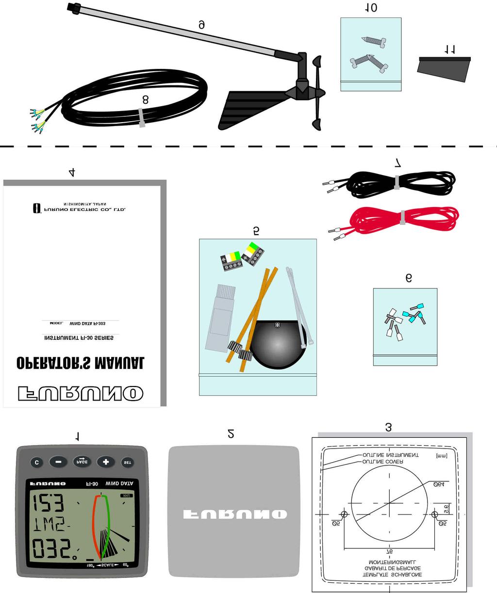
7 1 Part specifications FI-30 Wind Data is delivered with all parts for mounting. Check prior to installation. Wind Data instrument Qty Description Reference Instrument, FI-30 Wind Data Instrument front cover Drill template Operator s Manual Pin bolts for instrument mounting Nuts for instrument mounting Tube of silicon grease Connection cover 4-pol screw terminal Extra wire protectors, 0,25 mm (1/100 ) Extra wire protectors, 0,75 mm (1/32 ) Power cable, red and black, 3 m (9 ft) Additional in Wind Data complete with transducer Mast top cable. 25m (83 ft) Wind transducer FI-30 Mounting screws for mast bracket Mast head bracket
8 7
9 2 Installation You can install the FI-30 Wind Data in three different ways: The wind transducer connected directly to the FI-30 Wind Data instrument By using the connection kit when both log and wind transducers are installed with a single Wind Data. The installation may also include a FI-30 Server where all transducers may be connected. All data including power will pass along one cable. The installation includes 6 major steps: Read the installation and operation manual. Plan where to install the transducers and instruments. Run the cables. Install the transducers and instruments. Take a break and admire your installation. Learn the functions and calibrate your system. Before you begin drilling... think about how you can make the installation as neat and simple as your boat will allow. Plan where to position the transducers, Server and instruments. Think about leaving space for additional instruments in the future. A few do nots you should consider: Do not cut the cables too short. Allow extra cable length at the Server so it can be disconnected for inspection without having to disconnect all attached cables. Do not place sealant behind the display. The instrument gasket eliminates the need for sealant. Do not run cables in the bilge, where water can appear. Do not run cables close to fluorescent light sources, engine or radio transmitting equipment to avoid electrical disturbances. Do not rush, take your time. A neat installation is easy to do. The following material is needed: Wire cutters and strippers. Small and large Philips and small flat head screw driver. Hole saw for the instrument clearance hole 63 mm (2½ "). 1 5 mm ( /4") drill for the mounting holes. Plastic cable ties If you are doubtful about the installation, obtain the services of an experienced technician. 8
 hole saw to machine the clearance hole for the instrument connection socket. Remove the template.")
10 3 Installing the instrument Place the adhesive drill template on the desired location for the instrument. Drill 1 the 2 holes using a 5 mm ( /4") drill for the two pin bolts. Use a 63 mm (2½ ") hole saw to machine the clearance hole for the instrument connection socket. Remove the template. Screw the two pinbolts to the instrument Put the instrument in place Screw the two nuts from the back Note! The two nuts must just be tighten by hand Run the Nexus Network cable from the Server to the instrument. If you want to cut the Nexus Network cable to length, disconnect 4-pole jack plug and cut the cable. Peel off about 35 mm (1.4") of the cable insulation. Remove about 6 mm (1/4") from the 3 isolated wires (the 4th wire is an earth / screen). Attach the 4 cable protectors to the wires using a pair of flat pliers. Connect the 4 cable protectors to the 4-pole jack plug as shown. Apply silicon paste on all locations as shown. Note: Must be done to avoid corrosion. 9 Silicon paste

11 Apply silicon paste to the instrument connection pins at the back of the instrument. Press the jack plug onto the instrument pins. Press the cable in to the cable leads. Mount the connection back cover with the screw. Your instrument installation is done! 10
12 3.1 Installing cable The power cable is connected via a 3A fuse from the battery or at the boats fuse panel and direct to the instrument or Server. One red and one black power wire is included. Note, set C71 On (see 6.5.1) Scree n Black Green Yellow White Red 3A Fuse Always connect a 3 AMP fuse between Power supply and instrument. 3.2 Connections in Nexus Network If you already have a Nexus Network i.e. a Server, it is more practical to connect the transducer to the Server due to the single instrument cable installation. Note, set C71 OFF (see 6.5.1) Server Transducer The instrument is then connected to the Server s Nexus Network terminal (pin 5, 6, 7 and 8) or any instrument. From Server or other FURUNO instrument 11

13 3.3 Connection of log transducer If you have an other log instrument i.e. a FI-30 log, you may connect the single log pulse wire from that instrument to the Wind Data instrument terminal 4. From log transducer 3A Fuse If you don t have a log instrument, but want to install a log transducer, use the connection box. 12
14 4 First start (only in a Nexus Network) 4.1 Initialising the instrument At power on, the instrument will perform a self test. The display will first show all segments, then the software version number and the Nexus Network ID number. At first power on after installation, you will be asked to press SET [PrSSET]. This will give the instrument a logical ID number on the Nexus Network. To initialise the instrument, press SET on all installed digital instruments, one at the time. Note: Always wait for the text Init OK to be displayed, before you press SET on the next instrument! The Server automatically gives the first unit ID number 16, then 17 and so on. The order in which you press SET is the same order as the instruments will be given a logical ID number on the Nexus Network. The example shows that the instrument version number is 1.00 and the given logical ID number is Re-initialising the instrument If two instruments by mistake have the same ID number, this can cause disturbance and block the information on the Nexus Network. To re-initialise the instrument, press MINUS and PLUS together during the power up sequence when version and ID numbers are displayed. The display self test is then re-started on all instruments and you will be asked to press SET on each instrument as explained above. Note! If you do not succeed to re-initialise, we suggest you disconnect all but one instrument with the same ID number, then repeat the above procedure. 13
15 5 Operation 5.1 About this manual Each time a push-button are referred to in this manual, the push-button name will appear in bold and CAPITAL letters, e.g. PAGE. Unless otherwise stated, the push-button presses are momentary. Each time a function is mentioned in the text, it will be in brackets and in the same format, where possible, as displayed, e.g. [AWA]. This manual has been written to be: Compatible with Wind Data instrument from software version 1.0. All functions followed by the text option is not valid in a factory set-up instrument. See calibration to be able to display these functions. Note! We have put in a lot of effort in order to make this manual correct and complete. But since we continuously make our products better, some information can differ from the products functions. If you need further information contact your national distributor. 14
16 5.2 How to use the 5 push-buttons MAIN FUNCTION APPARENT WIND ANGLE INFOTEXT TRUE WIND ANGLE SUBFUNCTION TRIM FUNCTION CLEAR MINUS SET PLUS PAGE PAGE A press on PAGE change the PAGE of the graphical display. It scrolls in a circular pattern, one step for every press. The PAGE button is also used to move the cursor when in edit PAGE. A press on PAGE moves the cursor in a circular pattern, one step to the right for every press. A press on PAGE and MINUS together, back steps cursor to the preceding step. When in editing PAGE a long press (>2sec) on PAGE will escape from that editing PAGE MINUS A press on MINUS moves to the next sub-function. In edit PAGE it decreases to previous digit PLUS A press on PLUS moves to the previous sub-f unction. In edit PAGE it increases to next digit. 15

17 5.2.4 SET A press on SET unlocks a digit to access edit PAGE. When unlocked, the digits are active (flashes) and can be edited by pressing MINUS, PLUS and PAGE as required. When finished editing, lock the digit by another press on SET Clear A press on C, clear digits Calibration To access calibration PAGE, press and hold SET more than 2 seconds. To return to main function PAGE, press SET when the text return [RET] is shown Lighting The instrument uses red back lighting for the display and the 5 push-buttons. The lighting can be set at 4 different levels. 2 sec 2 sec To quick access the light control, press and hold PAGE for more than 2 seconds. The flashing text [Lit OFF] will be displayed and the display will be lit momentarily. To select between the 4 light levels, press PLUS: [LOW], [MID], [MAX] and [OFF]. To lock the selected level, press SET. The selected light level will be copied to all FI-30 instruments connected to the system. When the lighting is on, it is not possible to reduce or turn off the lighting on an individual instrument. 16
18 5.3 Main function Top data is relative Wind angle, [AWA] (Apparent Wind Angle). As an alternative to [AWA] the following can be displayed: [AWS] (Apparent Wind Speed). [TWA] (True Wind Angle) if the log transducer is connected. [TWS] (True Wind Speed) if the log transducer is connected. To change between these functions, see C12, Analogue function Change Wind scale between 180 and 60 with PAGE. Selected scale is shown with the LCD arrow pointing at scale. The text [APP] displays selected main function as apparent Wind angle or Wind speed. MIX 180 The text MIX 180 means that both APP and TRUE Wind angle is displayed in scale 180. MIX 60 The text MIX 60 means that both APP and TRUE is displayed in scale 60. The scale can be altered between 60 and 180 to get more accurate readings. At 2 scale 180 each sector represent 5 and at scale 60 each sector represent 1 /3. See the example below. WIND 17
19 5.5 Sub-functions Select sub-function with PLUS or MINUS. Information text for the sub-function is displayed. You may also park your favourite function so it will automatically be displayed after power on. Press both PAGE and SET to park the displayed function. The display will flash once to confirm that you have parked the function Apparent Wind Speed [AWS] The text [AWS] (Apparent Wind Speed) and its value is displayed below. The text [AWS] is toggled with the text [KTS] (KnoTS), [M/S] (Metres/S) or [BF] (Beaufort) True Wind Speed [TWS] The text [TWS] (True Wind Speed) and its value is displayed below. The text [TWS] (True Wind Speed) is toggled with the text [KTS] (KnoTS), [M/S] (Metres/s) or [BF] (BeauFort) True maximum Wind speed Press the SET in the sub-function: [TWS] to display maximum true Wind speed. After 5 seconds the display will go back to [TWS] again. Re-set or clear the [MAX] Wind speed value by pressing CLEAR or switch off the power Velocity Made Good (VMG) The text [VMG] (Velocity Made Good) is displayed with the actual boat speed towards or against the Wind. The water speed information from the log transducer is needed. The speed information can be taken from the log transducer or from Nexus Network. VMG = 0.0 knots when the true Wind angle is perpendicular to the boat. 18 WIND WIND
20 5.5.5 Battery voltage [BAT], option The text [BAT] will display battery voltage. The voltage is measured inside the instrument and will not compensate for any voltage drop caused by installation Boat speed [BSP], option The text [BSP] will display boat speed (water speed). The text [BSP] will toggle with selected unit, i.e. (KTS), (KMH) or (MPH). As an option, you may add or remove displaying boat speed [BSP], trip log [TRP] and water temperature [TMP]. See further under calibration Trip log [TRP], option The text [TRP] is displayed and will show trip distance from 0.00 to 99.9 nautical miles, kilometre or miles. After 99.9, 0.00 is displayed. Clear trip by pressing CLEAR Water temperature [TMP], option The text [TMP] is displayed with water temperature in Celsius or Fahrenheit. This function require a FI-30 log transducer Trim function for optimum Wind angle or speed, option The text [TRM] and [OFF] is displayed when this function is off. The trim function can be used as an aid to keep the correct tacking angle or to discover speed changes caused by sail or rig trimming. Some of the functions can only be used when the Wind Data is connected to Nexus Network. As the first example we will use [TRM AWA] (TRiM Apparent Wind Angle). To trim on wind angle deviation, select the text: Press CLEAR, the display will flash. Select [AWA] with MINUS and confirm with SET. Select the level of dampening [d0-d9] and confirm with the SET. The default (or latest used) Wind angle is displayed. You may accept the proposed angle by pressing the SET or enter a new Wind angle with PLUS, MINUS and PAGE before confirming with SET. The entered Wind angle will be lost when power off. You may however select a default Wind angle in set-up. See C Every time you select this function, or after power up, the pre-set value is proposed. 19
21 On the display you will see the text TRM and AWA toggling together with your Wind angle. On the graphic part you will see your reference angle as one straight horizontal segment when actual angle is equal to the pre-set angle. At the same time you will see apparent and true Wind angle. The deviation is displayed visible upwards or downwards from the horizontal line to +/-15. The maximum visible deviation is 15. When the deviation is between 15 and 30 the 15 sector is lit. When larger then 30 the segment sector is blanked out. Trim on speed: Each sector represents 2% Select the trim function. Press CLEAR. Select text (BSP) by pressing PLUS and confirm with SET. There is a number of different speeds to be used for trimming. The most common is [BSP] (Boat SpeeD) and [VMG] (Velocity Made Good). The Wind Data instrument can also display deviation from optimum calculated boat speed [TBS] or (Target Boat Speed). The TBS is normally calculated by use of polar diagram on PC with racing software. The value Target Boat Speed is transmitted through the FI-30 Server on the NMEA 0183 input. The Server will then transmit TBS on the Nexus Network. On the Wind Data display you will see both the digital value in % and the graphical value as a 2% variation for each segment. You may select speeds to TRIM, from this list: BSP AWS TWS SOG DRF Boat speed Apparent Wind Speed True Wind Speed Speed Over Ground Drift WCV VMG TBS Speed towards a waypoint Velocity Made Good Optimum speed based on polar diagram OFF Function is OFF Log transducer! Log transducer! Navigator! Log transducer + Compass + Navigator! Navigator! Log transducer! PC + NMEA 0183 through FI-30 Server! When [BSP] (or other function) is selected, the dampening [d3] is flashing. Select dampening level and confirm with SET. The text [% OFF] is then displayed to show that the function is selected, but no reference is yet set. 20
22 Press SET to set [BSP] reference. The display will now show you the text [%] toggling with text [BSP] or whatever trim you have selected. The speed variation is expressed in % from set value. Press the SET every time you wish to set a new trim reference value. There is an option to use an external trim button to set a new trim reference. See more in the calibration. Each sector represents 2% 5.6 More functions in a Nexus Network By adding (or using) the Wind Data instrument in the Nexus Network, more functions will be added if the corresponding transducer is connected. The Wind Data functions may be added or removed by the user. The Wind Data instrument can be used in a small Network together with the Multi, Log or analogue instrument, without a Server. In order to make the installation easy when using both log and Wind transducer in a small Network we recommend you to install with connection kit art.no Only one cable will carry the signals to the instrument, then there is one Network/power cable to the Multi or Log instrument. (See 3.3). When using the Wind Data in a bigger Network with more then 3 transducers, we recommend you to use the FI-30 Server. Only one cable will be used to connect all instruments. You will also have the NMEA 0183 input/output. If you need to be able to read the depth information on more then one instrument, the Server is the only choice. Network bonus function: If you are using the race timer on the Multi or Log instrument you will have a graphical 60 second countdown timer popping up on this instrument. In this example there is 45 second to start. 21
23 5.6.1 Geographic Wind direction (TWD) To get this function, set NAV = On C14 (See 6.1.4). Text [TWD] is displayed shortly, then is the abbreviation for Wind directions displayed, [SSW], [NO], [WNW] etc. together with the numerical direction below. The graphic direction is also displayed by pressing PAGE one or more times until the display to the right is displayed together with the pointer. If the Compass transducer is missing but there is a GPS installed, you may use the GPS as a reference for heading under the criteria that the vessel must be moving. Change C33 from USE Hdc to USE COG. (See 6.3.3) When the boat is laying still, the TWD will be random readings if COG is used. You may also check long term geographical Wind shifts by entering a marker at present Wind direction as a remainder. The marker will stay until power off or by clearing the function. A Wind shift of 5 will be easy to detect after hours of sailing. Select function [TWD 360 ] with PAGE, and when the text [TWD] is flashing press SET. The marker is now set. When there is a constant Wind shift, you will see this marker as a slow blinking reminder of the origin Wind direction. Each sector represents WCV, Waypoint Closing Velocity To get this function, set NAV = On C14 (See 6.1.4). The text [WCV] is displayed with the actual speed towards your Waypoint if a Waypoint is selected in your GPS navigator. 22
24 5.6.3 X-track error, XTE To get this function, set NAV = On C14 (See 6.1.4). The text [XTE] is displayed shortly when this function is selected, then a symbolic boat is displayed on one side of the road which is displayed as three vertical lines. Your boat will be displayed on the right or left side of the road. The distance is also displayed and can be in either Nautical mile, Km or Miles HDC / NXT, Course after tack or jibe To get this function, set NAV = On C14 (See 6.1.4). This function also needs a Compass connected to the FI-30 Server If the Compass sensor is missing, the HDC may be replaced by the COG (Course over ground) by setting the reference in COG. (See C ). The text [HDC] is displayed with actual magnetic or true heading. After 4secs. the text [NXT] together with the true or magnetic course to keep after tack or jibe. Note! The boat s drift must be included in your decision when to tack, to reach the mark. After a tack, it will take some minute before the new tack angle is steady due to the dampening. The functions [HDC] and [NXT] is toggling, but they can be locked or unlocked by use of the SET. 23
25 5.6.5 BTW / NXT, Bearing and angle deviation relative next course To get this function, set NAV = On C14 (See 6.1.4). This function is using both the Compass and the navigator information to calculate the angle deviation between the bearing and the course after tack. i.e. the angle deviation is exactly what you should expect after the tack. [BTW] is showing the actual Bering to Waypoint and [NXT] is showing the negative [-], positive tack or downwind angle that you would expect if you where tacking or jibing. You may use COG but our recommendation is to use the Compass since the response and accuracy is superior. If you use COG without a differential GPS you will loose too much accuracy in the information. [BTW] and [NXT] is toggling. TACK : Example: If you expect your drift to be 05, your tack should be made when you read [NXT 05 ] to be on (and stay on) lay line. While you are approaching the proper angle, the value is negative, i.e. -12 and then increasing to 00 which is on lay line after tack except for the drift which is the margin you must add to compensate for the drift. Note! This function is only used on the last leg. WIND 24
26 Down Wind: When sailing down Wind, the boat can always be sailing at the highest WCV (speed towards the mark). When [NXT] is [00 ] you should jibe because your drift is not important. The functions [BTW] and [NXT] is toggling, but can be locked or unlocked by use of the SET. Note! This function is only used on the last leg. WIND 25
27 6 Calibration To get the most out of your FI-30 instrument, it is important to carefully calibrate the instrument. The calibration values are stored in a non volatile memory. To access calibration PAGE, press and hold SET more than 2 seconds. To select a calibration code, press MINUS, PLUS and PAGE as required. To return to normal operation PAGE, press SET when the text return (RET) is displayed. The different calibration routines are divided into five groups: C10 - C15 = USR, User settings. C20 - C24 = BSP, Log transducer and temp calibrations. C30 - C33 = HDC, Compass settings. C50 - C64 = WND, Wind transducer settings/calibrations. C70 - C74 = CON, Configuration of the FI-30 system. To change a calibration value, press SET. To select calibration value, press MINUS, PLUS and PAGE as required. To lock the selected value, press SET. 6.1 C10 User settings To return to normal PAGE, press SET when the text [ret] is displayed C11 Select the dampening The dampening will affect Wind angle, Wind speed, boat speed and VMG. Dampening is between d0 (0s) and d9 (1 20). To change the dampening, press SET and change with PLUS or MINUS and enter with SET C12 Select main information Select function to be display at the top left of the LCD display. There is five options. AWA Apparent Wind Angle. TWA True Wind angle by the use of log transducer. AWS Apparent Wind speed. TWS True Wind speed by use of log transducer. WIA Main setting for the FI-30 system. When selected, all instruments using WIA will be system affected and following the set-up in the Multi Control setting C51. 26
28 6.1.3 C13 Displaying boat speed, trip log and temperature, option When set to OFF, the functions will be removed from the display. The Wind Data instrument may be used as a Server in the Nexus Network, transmitting the log and temp to other FI-30 instruments without having the information displayed in this instrument C14 Display NAV functions, option NAV functions are only useful when the Wind Data is connected in a Nexus Network with Compass transducer and a navigator. The selection NAV On will add the functions BTW, XTE etc C15 Beep when SET is pressed Setting On will make a beep at every key press, while OFF is silent. 6.2 C20 Calibration of Log To return to normal PAGE, press SET when the text [ret] is displayed C21 Select unit for speed Unit for speed, knots (KTS), km/h (K/h) or miles/h (m/h) C22 Calibration of log transducer Calibration value for speed and distance ( ). Drive the boat a measured distance at normal speed. Compare the distance with the trip counter. Calculate the value with the following formula. True distance from the sea chart: Log trip counter distance: The current calibration value: New calibration value: T L C N If you suspect a current in the water, drive the boat in both directions and divide trip counter distance by two. If the Wind Data is installed with FI-30 Server where the log is already calibrated, no further calibration is needed. 27
29 6.2.3 C23 Unit for temperature Select degree Celsius [C] or degree Fahrenheit [F] C24 Temperature offset By adding a positive or [-] negative value here, it will be added as an offset before displayed as the temperature. 6.3 C30 Compass Settings To return to normal PAGE, press SET when the text [ret] is displayed C31 True or magnetic course This function is only used when the instrument is connected in the Nexus Network. [MAG On] will display bearing, course and Wind direction as magnetic. The LCD indication is (MAG). Select [OFF] to display all as true C32 Magnetic deviation Set the deviation direction first, i.e. [+E] (East) or [W] (West), then enter the magnetic value in 1/10 of a degree C33 Reference for Compass, static or GPS Select heading Compass [Hdc] when the Compass transducer is connected to the Nexus Network (recommended). Select course over ground [COG] when a GPS navigator is connected, but no Compass. Select STA for static use at fixed installations, such as at the yacht club, airfield, ferry berth and so on. In static PAGE you may mount the transducer in the direction of North, or if not possible, you may adjust the transducer electronically. See C54, Note! [COG] as reference will only operate properly when the boat is doing speed over ground. 28
30 6.4 C50 Wind Settings To return to normal PAGE, press SET when the text [ret] is displayed C51 Network setting of true or apparent Wind angle Select true [TWA] or apparent Wind angle [AWA] as main function. The optional analogue Wind instrument will display the same selection. All Multi Control instruments which have the calibration code 63 set to [WIA] will display what is selected in C C52 Unit for Wind speed Unit for Wind speed [KTS] for (KnoTS), [M/S] for (Metres/S) and [BF] for (Beaufort) C53 Wind speed calibration Do not change this factory setting C54 Adjustment of Wind angle Mast top unit misalignment adjust value or the so called A-fault, makes it possible to adjust any horizontal angle. Example: If the Wind angle is +4 when you sail/drive the boat straight into the Wind, set the calibration value in C54 to C55-C62 Calibration table for the Wind transducer In channels C55 to C62 you set the calibration values for the mast top unit. Each mast top unit is individually calibrated for best accuracy. See the separate Wind calibration certificate supplied with each mast top unit. Each of the inter-cardinal directions are calibrated. C55 C56 C57 C58 C59 C60 C61 C Set the calibration value according to the provided calibration certificate 29
31 6.4.6 C63 Speed reference, water or GPS This function is only used when the instrument is connected in the Nexus Network. When [BSP] is selected, the reference is water speed provided by the log transducer for calculation of true Wind speed and angle, VMG and NXT function together with the BTW. When [SOG] is selected, the reference is speed over ground. Note! the boat must be moving to give correct readings. We also recommend you to use differential GPS to get good readings C64 Wind trim reference This default reference for Wind angle trim. Each time the instrument is powered up and apparent Wind angle is selected as trim reference this value will be pre-set C68 Roll adjustment This adjustment is valid only if roll is selected in C73 (you have to exit and enter the calibration again after C73 is set to Roll.) Adjustment of the roll offset. Mount the roll transducer according to the instructions. Adjust the offset so the roll is displaying 00 when the boat is horizontal. By entering a minus sign [-] in front of the value the roll will be decreased by the value. When the offset is without a minus sign, it will be added. When a roll transducer is connected the Wind- speed and angle will be compensated for roll and accuracy is increased. The roll sensor is not yet available (at the time for this manual) C69 Pitch adjustment This adjustment is valid only if roll is selected in C73 (you have to exit and enter the calibration again after C73 is set to Roll). Adjustment of the pitch offset. Mount the pitch transducer according to the instructions. Adjust the offset so the pitch is displaying 00 when the boat is horizontal. By entering a minus sign [-] in front of the value the roll will be decreased by the value. When the offset is without a minus sign, it will be added. When a pitch transducer is connected the Wind speed and angle will be compensated for pitch and accuracy is increased. Pitch does not affect Wind speed and angle as much as roll. 30
32 6.5 C70 Configure FI-30 To return to normal PAGE, press SET when the text [ret] is displayed. In the configuration you will be able to tell the Nexus Network where you have installed the log and Wind transducer. This is important because you may optionally install those transducers at the Server too C71 Wind-master [On] = the Wind transducer is connected at the Wind Data instrument. [OFF] = the Wind transducer is connected at the FI-30 Server C72 Log-master [On] = the log transducer is connected at the Wind Data instrument. [OFF] = the log transducer is connected at the FI-30 Server C73 Function on terminal In3 Select function on the terminal pin 3. The following functions are available: [TMP] [TRM] [SPT] [MOB] [Roll] Standard temperature function from the log transducer. Use the external trim button for the STEER Pilot function. Use the external trim button for the SPEED TRIM function. Use the external trim button for the M.O.B. function. Use the roll sensor to compensate Wind speed and angle. (Not yet available, at the time for this manual). When the selection roll is made, further settings in calibration can be made to correct the offset angle. See C You may still use the water temperature by connecting the log transducer at the Server. When Speed Trim [SPT] is selected, a press on the external trim button will transmit the trim command on the Network to all instrument. To be able to set both the STEER reference and the TRIM reference, the optimum way is to connect one trim button for speed to the Wind instrument and connect one trim button for Compass and Wind angle to the Server. Such a installation gives you the opportunity to trim speed and angle at two separate buttons. 31
33 6.5.4 Connection of trim button Connect the trim button as per the drawing. The button should make connection when pressed. It is also possible to connect more than one button in parallel, for example one on starboard and one on port. Article number for the push button: C74 Demo PAGE The Wind Data instrument has a built in demonstration PAGE. All values are simulated in this PAGE. It is convenient to learn the functions of the instrument by using this PAGE. Every 7th second the text DEM will appear to alert you that demo PAGE is selected. 32
34 7 Maintenance and fault finding 7.1 Maintenance To clean the instrument, use only mild soap solution and rinse with water. Do not use detergents or high pressure washing equipment. At least once a year, check all your connections and apply additional silicon paste at each connection point. Always use the instrument cover for protection, when not in use. Storing transducers and instruments when not in use for longer periods: It is advisable to remove the instruments and transducers, and store them inside the boat or at home in room temperature, if possible. 7.2 Fault finding Before you contact your FURUNO dealer, and to assist your dealer to give you a better service, please check the following points and make a list of: All connected instrument and transducers, including their software version numbers. Instrument software version number. Nexus Network data bus ID numbers for each instrument (displayed at power up) General In most cases, the reason for faults in electronic equipment is the installation or poor connections. Therefore, always first check that: Installation and connection is made per instructions for instrument and transducers, (see 3.3). Screw terminals are carefully tightened. No corrosion on any connection points. No loose ends in the wires causing short cuts to adjacent wires. Cables for damage, that no cables are squeezed or worn. Battery voltage is sufficient, should be at least 10 V DC. The fuse is not blown and the circuit-breaker has not opened. The fuse is of the right type. Two instruments do not have the same ID number, (see 4.2). Check the following important settings: C13, C14, C33, C63, C71 and C72. 33
35 7.2.2 Fault - action 1. Wind: No reading [ --- ] If inaccurate Wind data is received, check the connections (separate through deck connection or below decks connection), are properly made. Make sure the transducer is aligned correctly, (see C54, 6.4.4). Measure with a voltmeter, at the screw terminal pin 1 and ground, and between pin 2 and ground. If the voltmeter shows 1.5 to 4 V DC (minimum Wind speed 3 m/s) at both measuring points, the transducer and the connections are OK. If the voltmeter shows 0 or 5 V DC at both measuring points, the transducer or the connections are defect. Contact you FURUNO dealer with this information. 2. Speed and distance functions: No reading [ --- ] C13 should be ON. See If you have a voltmeter available, you can check the condition of the transducer. When measuring with voltmeter make sure everything is connected, that the power is on and make sure the paddle wheel is rotating. At the back of the instrument, measure between pin 4 and ground. When not rotating, the value should be fixed at either about 0 or 5 V DC. When rotating very slowly, by hand, the value should flip between 0 and 5 V DC. When rotating faster, the value should average around 2.5 V DC. Irregular values: Check the speed damping (SEA), (see C11, 6.1.1). 3. Compass functions: No reading [ --- ] C14 should be ON. See Error messages The following error messages can appear on the display: ERROR 2 ERROR 3 ERROR 10 ERROR 11 Nexus Network is missing, check colour coded connections No Network data received within a given time. Range error caused by bad format, e.g Remote command that can not be performed. If other error messages than the above appears on the Wind Data instrument, contact your FURUNO dealer. 34
36 8 Specifications 8.1 Technical specifications Dimensions: Wind Data instrument: 113 x 113 mm. (4.3x4.3 inch) Instrument cable: Power supply: Power consumption Instrument: Log- and temp sensor: Wind transducer: Temperature range: Weight: Enclosure: 12 V DC (10-16 V). The instrument is polarity protected W 0.8 W (at max illumination) 12 mw 50 mw Storage: From -30 C to +80 C.( -22 F to 176 F) Operation: From -10 C to +70 C. (14 F to 158 F) Instrument: 283 g (9.98 oz). Transducer: 293 g (10.33 oz). Instrument. Water proof CE approval The products conforms to the EMC requirements for immunity and emission according to EN , 8.2 Nexus Network introduction and user policy Introduction: The Nexus Network is a Multi talker Multi receiver data bus specially designed for marine navigation applications. It utilises the RS485 standard with up to 32 senders and/or receivers to form a Local Area Network. Data is transmitted synchronously with 1 start-bit, 8-data-bits, 1 parity-bit, two stop-bits in 9600 baud. User policy: The Nexus Network is open for new users and applications without the licence or a licence fee. The data bus however is, the property of the manufacturer, which means the specification must be followed in order to protect the manufacturer s commitments to the Nexus Network performance and safety. For most PC-applications, the full duplex interface, will be a very useful tool for monitoring real time data, to edit and store Waypoints to PC-file or to Server. The interface is supplied with a cable for connection from PC to the Server or FI-30 instruments. A 9-pole D-sub connector is connected to the RS232 port on the PC. 35
37 9 Equipment Lists INSTRUMENT SERIES PART # MODEL FI FI-301-SERVER FI-301-SERVER/SENSOR FI FI-302-SENSOR FI FI-303-SENSOR FI FI FI FI FI FI FI-310 MULTI CONTROL MULTI CONTROL W/SERVER MULTI CONTROL W/SERVER & SENSORS SPEED SPEED W/ST SENSOR WIND DATA WIND DATA W/WIND SENSOR COMPASS DATA MULTI XL ANALOG WIND ANGLE STEER PILOT SPEED TRIM RUDDER ANGLE ANALOG COMPASS ACCESSORIES PART # MODEL FI-3001-DEPTH FI-3002-LOG FI-3003-WIND FI-3004-COMPASS FI-3005-SERVER FI-3006-DEMO-SERVER FI-3007-BUZZER FI-3008-MOB FI-3009-CABLE-100M FI-3010-CABLE-8M FI-3011-CABLE-0.3M FI-3014-MASTCABLE-25M DEPTH TRANSDUCER ST SENSOR WIND SENSOR FLUXGATE COMPASS SERVER SERVER SIMULATOR EXTERNAL ALARM BUZZER MOB BUTTON INTERCONNECTION CABLE 100M INTERCONNECTION CABLE 8M INTERCONNECTION CABLE 0.3M WIND MAST CABLE 25M 36
38 10 Abbreviations BSP BTW C F KM KTS MH LCD LOW MID MAX RET SOG TRP _ Boat Speed Bearing To Waypoint Celsius Fahrenheit KiloMetre KnoTS Miles per Hour Liquid Crystal Display LOW MID MAX RETurn Speed Over Ground TRiP Minus Plus 37
39 38
40 Edidtion 1 39
WIND. - Instrument - Installation and Operation Manual English
 - Instrument - Installation and Operation Manual 1 Introduction Thank you for choosing Star Wind instrument. We are convinced that you will appreciate all the valuable information either you are a cruiser
performance by NEXUS NETWORK WIND Data - Instrument - Installation and Operation Manual English
 performance by NEXUS NETWORK WIND Data - Instrument - Installation and Operation Manual English 4-1 Introduction Thank you for choosing NX2 Wind Data instrument. We are convinced that you will appreciate
Compass. - Instrument - Installation and Operation Manual English
 Compass - Instrument - Installation and Operation Manual COMPASS 5-1 COMPASS Introduction Thank you for choosing NX2 Compass instrument. We are convinced that you will appreciate all the valuable information
INTRODUCTION TO NETWORK WIND 3 MOUNTING THE UNIT 14 SELECTING THE DISPLAY MODE 5 ABBREVIATIONS AND DEFINITIONS 17
 CONTENTS CONTENTS 1 INSTALLATION 14 GENERAL INTRODUCTION TO B&G NETWORK 2 SITING THE UNIT 14 INTRODUCTION TO NETWORK WIND 3 MOUNTING THE UNIT 14 EXAMPLE SYSTEMS USING NETWORK WIND 4 SPECIFICATION 16 SELECTING
performance by NEXUS NETWORK Compass - Instrument - Installation and Operation Manual English
 performance by NEXUS NETWORK Compass - Instrument - Installation and Operation Manual COMPASS 5-1 COMPASS Introduction Thank you for choosing NX2 Compass instrument. We are convinced that you will appreciate
- Instrument and Server - Installation and Operation Manual
 - Instrument and Server - Installation and Operation Manual 0 Navigation terms BOD: Bearing origin destination BTW: Bearing to Waypoint CMG: Course made good COG. Course over ground CTS: Course to steer
Multi Control - Instrument -
 Multi Control - Instrument - Installation and Operation Manual English English 1 Navigation terms 2 This manual is written for NX2 Multi Control version 3.1 5.0 Edition: March 2007 3 1 Part specification...
PART 5 - OPTIONS CONTENTS 5.1 SYSTEM EXPANSION 5-3
 PART 5 - OPTIONS CONTENTS Para Page 5.1 SYSTEM EXPANSION 5-3 5.2 SENSORS 5-3 5.2.1 Trim Angle Sensor 5-3 5.2.2 Mast Rotation Sensor 5-3 5.2.3 Heel Angle Sensor 5-3 5.2.4 Barometric Pressure Sensor 5-3
TOP BLEED Position for SeaTalk 2 colour logo ST 30. COMPASS Operation and Installation
 Distributed by Any reference to Raytheon or RTN in this manual should be interpreted as Raymarine. The names Raytheon and RTN are owned by the Raytheon Company. TOP BLEED Position for SeaTalk 2 colour
GNX 20/21. Owner s Manual
 GNX 20/21 Owner s Manual Table of Contents Introduction...1 Device Overview... 1 Using the Race Timer... 1 Profiles... 1 Selecting a Profile... 1 Restoring Profiles to their Default Settings... 1 Instrument
GNX Wind. Owner s Manual
 GNX Wind Owner s Manual February 2016 190-02003-00_0A All rights reserved. Under the copyright laws, this manual may not be copied, in whole or in part, without the written consent of Garmin. Garmin reserves
GNX 120/130. Owner s Manual
 GNX 120/130 Owner s Manual March 2016 190-01846-00_0B All rights reserved. Under the copyright laws, this manual may not be copied, in whole or in part, without the written consent of Garmin. Garmin reserves
- Course Processor R
 http://nex / /Autopilot/dig_auto.tif Autopilot - Course Processor R-1600 - Installation and Operation Manual AUTOPILOT 8-1 AUTOPILOT This manual is written for NX2 Autopilot version 1.00 Edition: May 2012
mn100 Analog Display
 mn100 Analog Display uu040 rev. 8 mn100 Analog Display EMC Conformance All Tacktick equipment is designed to the best industry standards for use in the recreational marine environment. The design and manufacture
CONTENTS STEER TO VANE MODE...
 CONTENTS GENERAL INTRODUCTION TO B&G NETWORK... 2 INTRODUCTION TO NETWORK PILOT... 3 SWITCHING THE NETWORK PILOT ON... 3 NETWORK PILOT DISPLAY UNIT... 4 NETWORK PILOT HAND-HELD CONTROLLER... 5 JOYSTICK
Sail Racing Instruments. Aspect 40
 Sail Racing Instruments www.nexusmarine.se Presentation Nexus Marine is a leading manufacturer of navigation instrumentation for racing and cruising yachts. Nexus brings with it seventy years of experience
WIND CLIPPER KTS ILLUM SCALE INC DEC CLIPPER WIND SYSTEM
 CLIPPER WIND KTS ILLUM SCALE DEC INC CLIPPER WIND SYSTEM TABLE OF CONTENTS INTRODUCTION PRE-TEST OF INSTRUMENT INSTALLING THE MASTHEAD SENSOR UNIT INSTALLING THE DISPLAY NORMAL OPERATION CHANGING THE
GNX 20/21. Owner s Manual
 GNX 20/21 Owner s Manual March 2016 190-01659-00_0C All rights reserved. Under the copyright laws, this manual may not be copied, in whole or in part, without the written consent of Garmin. Garmin reserves
Copyright 2004 by the Thomas G. Faria Corporation, Uncasville CT No part of this publication may by reproduced in any form, in an electronic
 Copyright 2004 by the Thomas G. Faria Corporation, Uncasville CT No part of this publication may by reproduced in any form, in an electronic retrieval system or otherwise, without the prior written permission
USER GUIDE FOR DATALINE-X SDX. Stowe Marine Ltd. Tel +44(0)
") USER GUIDE FOR DATALINE-X SDX Stowe Marine Ltd. www.stowemarine.com Tel +44(0)1590 610071 Dataline-X SDX Manual, Part Number 05707SM, Issue 2, Dec 1995. Warning The equipment to which this manual applies
USER GUIDE FOR DATALINE-X SDX Stowe Marine Ltd. www.stowemarine.com Tel +44(0)1590 610071 Dataline-X SDX Manual, Part Number 05707SM, Issue 2, Dec 1995. Warning The equipment to which this manual applies
frequently asked questions
 Hydra Pilot Fault Codes What do the fault codes for the Hydra Pilot mean? Fault Cause FAULT 100 FAULT 101 FAULT 102 FAULT 103 FAULT 104 FAULT 105 FAULT 106 FAULT 108 FAULT 109 FAULT 110 FAULT 111 FAULT
TECNAUTIC_GmbH. Display Functions with the PB100/200 connected: -- GND Speed -- GND Course -- Heading (Gyro option is recommended) 2 m
 2 m") PB100/200 Sonic Wind Wind, GPS, Compass Display Config: SE=12 di=00 df=20,91,30,34,(61) 35,36,81 Gr=01 n0=00 n1=07 n2=07**) n3=00 Display Functions with the PB100/200 connected: -- Apparent Wind -- True
PB100/200 Sonic Wind Wind, GPS, Compass Display Config: SE=12 di=00 df=20,91,30,34,(61) 35,36,81 Gr=01 n0=00 n1=07 n2=07**) n3=00 Display Functions with the PB100/200 connected: -- Apparent Wind -- True
OPERATION AND INSTALLATION MANUAL
 AP46 Autopilot OPERATION AND INSTALLATION MANUAL www.tmq.com.au TMQ AP46 Autopilot Page 1 of 34 Ver1.0 07/03/2007 This page is Blank TMQ AP46 Autopilot Page 2 of 34 Ver1.0 07/03/2007 WARNING!...4 INTRODUCTION...5
Before installing to a boat of aluminum or steel construction, please contact your Tacktick dealer.
 Analogue Display mn100 Analogue Display EMC Conformance All Tacktick equipment is designed to the best industry standards for use in the recreational marine environment. The design and manufacture of Tacktick
GNX 20/21 Owner s Manual
 GNX 20/21 Owner s Manual February 2014 190-01659-00_0B Printed in Taiwan All rights reserved. Under the copyright laws, this manual may not be copied, in whole or in part, without the written consent of
EMC Conformance. Important
 Digital Display mn100 Digital Display EMC Conformance All Raymarine equipment is designed to the best industry standards for use in the recreational marine environment. The design and manufacture of Raymarine
Steer to Wind angle, Wind Mode, when connected to the h1000 Wind Interface
 h1000 pilot introduction overview Congratulations on your purchase of the h1000 Pilot from B&G. The h1000 Pilot is the latest in autopilots from B&G and represents B&G s commitment to providing our customers
Depth sensor. Product reference : REV 1. USER GUIDE and INSTALLATION GUIDE. nke Sailing competition
 Depth sensor Product reference : 90-60-456 REV 1 USER GUIDE and INSTALLATION GUIDE nke Sailing competition Z.I. Kerandré Rue Gutenberg 56700 HENNEBONT- FRANCE http://www.nke.fr After sale service n 33
TS-202 FFU Lever Remote Part Number & Operation & Installation Instructions Version 2.1
 R TS-202 FFU Lever Remote Part Number 20310020 & 20310029 Operation & Installation Instructions Version 2.1 ComNav Marine Ltd. 15 13511 Crestwood Place. Richmond, B.C. Canada. V6V-2G1 Document PN 29010046
h1000 system user manual
 h1000 system user manual HB-1000D Issue: 0001 h1000 introduction overview Congratulations on your purchase of the h1000 System from B&G. The h1000 navigation system combines clever thinking with incredibly
Tacktick Wireless Instruments
 Tacktick Wireless Instruments 2 The wireless revolution has already begun Across the globe, sailors and boat owners are experiencing the benefits of Tacktick s groundbreaking Micronet wireless and solar
ST40 Bidata Instrument Owner s Handbook. Document number: Date: March 2006
 Bidata Instrument Owner s Handbook Document number: 81159-3 Date: March 2006 Raymarine, and SeaTalk are trademarks of Raymarine UK Ltd Handbook contents copyright Raymarine UK Ltd. Preface i Important
USER MANUAL. Premier Way, Abbey Park Romsey Hampshire, SO51 9DH, UK. Tel: (+44) Fax: (+44)
 Fax: (+44)") USER MANUAL Premier Way, Abbey Park Romsey Hampshire, SO51 9DH, UK Tel: (+44) 01590 689699 Fax: (+44) 01590 610072 www.bandgservice.co.uk Brookes and Gatehouse Ltd. 2000 The copyright of this Manual is
USER MANUAL Premier Way, Abbey Park Romsey Hampshire, SO51 9DH, UK Tel: (+44) 01590 689699 Fax: (+44) 01590 610072 www.bandgservice.co.uk Brookes and Gatehouse Ltd. 2000 The copyright of this Manual is
iregatta User Manual
 iregatta User Manual iregatta User Manual This manual may not always be up to date with the latest version of iregatta available in Apples App Store, as minor additions or bug fixes may be published without
MANUAL. P C - C E N T E R Version Copyright by Dinand van het Reve CONTENTS
 P C - C E N T E R Version 4.00 Copyright 1995-2004 by Dinand van het Reve CONTENTS 1. Introduction 2. Installing PC-CENTER 3. Licence 4. Using PC-CENTER 5. Description of 'Small Windows' 6. Main Menu Description
User s Guide. Leisure Pilots 715, 730 & 740. for. Issue 06 for use with version V3.00 software (or later) in the Pilot Computer
 in the Pilot Computer") User s Guide for Leisure Pilots 715, 730 & 740 Issue 06 for use with version V3.00 software (or later) in the Pilot Computer Welcome... All of us at would like to welcome you to the reliable world of our
User s Guide for Leisure Pilots 715, 730 & 740 Issue 06 for use with version V3.00 software (or later) in the Pilot Computer Welcome... All of us at would like to welcome you to the reliable world of our
Autopilot setup. VRF (Virtual Rudder Feedback) calibration. Software setup NSS evo2 Installation Manual
 calibration. Software setup NSS evo2 Installation Manual") Autopilot setup Verifying the autopilot connection When an AC12N, AC42N, or SG05 is connected to the NSS evo2 system, the NSS evo2 will automatically detect the autopilot and an Autopilot menu icon will
Autopilot setup Verifying the autopilot connection When an AC12N, AC42N, or SG05 is connected to the NSS evo2 system, the NSS evo2 will automatically detect the autopilot and an Autopilot menu icon will
SG33KTL-M Quick Installation Guide. 1 Unpacking and Inspection
 SG33KTL-M Quick Installation Guide This guide provides a general instruction of the installation procedures of SG33KTL-M. In no case shall this guide substitute for the user manual or related notes on
INSTALLING THE ECHO SOUNDER TRANSDUCER CHANGING THE OPERATING CONFIGURATION
 INTRODUCTION INSTALLING THE DISPLAY INSTALLING THE LOG PADDLE WHEEL UNIT INSTALLING THE ECHO SOUNDER TRANSDUCER NOTES ON ELECTRICAL INTERFERENCE USING THE INSTRUMENT SETTING THE MINIMUM DEPTH ALARM SETTING
INSTALLATION INSTRUCTIONS AND REFERENCE HANDBOOK
 INSTALLATION INSTRUCTIONS AND REFERENCE HANDBOOK APPLICATION NOTES WIND MEASURING SYSTEMS Document no.: 4189340577BC SW version AGC 3.4X0.X0 or later and AGC 4.00.0 or later Document no.: 4189350050A Table
SG36KTL-M Quick Installation Guide. 1 Unpacking and Inspection
 SG36KTL-M Quick Installation Guide This guide provides a general instruction of the installation procedures of SG36KTL-M. In no case shall this guide substitute for the user manual or related notes on
Installation, Compensation and Maintenance Instructions for. RITCHIE Compasses. Made In U.S.A
 Installation, Compensation and Maintenance Instructions for RITCHIE Compasses Made In U.S.A All Magnetic Compasses are vulnerable to magnetic interference, which will produce errors, called deviation.
S100 Controller. User guide. English Date: Document number: EN 2006 Raymarine UK Limited
 S100 Controller User guide English Date: 06-2006 Document number: 81242-4-EN 2006 Raymarine UK Limited 1 - Getting Started Changing the Controller batteries... 5 The S100 Autopilot Controller... 6 How
SP-110 Autopilot OPERATION
 SP-110 Autopilot OPERATION www.si-tex.com Warning! WHEN USING THE AUTOPILOT AN ADEQUATE WATCH SHOULD BE MAINTAINED AT ALL TIMES. THE AUTOPILOT MUST BE PLACED IN MANUAL MODE WHEN EVER THE VESSEL IS STATIONARY
GHC Remote Control Instructions manual
 GHC Remote Control Instructions manual Instructions What s In The Box Before installing your remote, confirm that your package includes these items. GHC Remote Control Two GHC Remote Control cradles Four
Race Master System User Guide
 User Guide EMC Conformance All Tacktick equipment is designed to the best industry standards for use in the recreational marine environment. The design and manufacture of Tacktick equipment conforms to
ST70 Autopilot Controller User Reference Guide
 ST70 Autopilot Controller User Reference Guide Document reference: 81288-2 Date: May 2010 ii iii Contents Preface Warnings and cautions WARNING: Product installation & operation This equipment must be
APPLICATION NOTES. WIND MEASURING SYSTEMS using XDi-N indicators. Document no.: B
 APPLICATION NOTES WIND MEASURING SYSTEMS using XDi-N indicators Document no.: 4189350080B Table of contents GENERAL INFORMATION... 4 WARNINGS, LEGAL INFORMATION AND SAFETY... 4 LEGAL INFORMATION AND DISCLAIMER...
Dual Digital Display
 Dual Digital Display mn100 Dual Digital Display EMC Conformance All Tacktick equipment is designed to the best industry standards for use in the recreational marine environment. The design and manufacture
LX Compass module 3 Electronic compass device User manual
 LX Compass module 3 Electronic compass device User manual LX navigation d.o.o., Tkalska 10 SLO 3000 Celje, tel: + 386 3 490 46 70, fax: + 386 3 490 46 71 info@lxnavigation.si, http://www.lxnavigation.com
GV Standard X-Vent. Setup, Commissioning & Installation Guide
 GV Standard X-Vent Setup, Commissioning & Installation Guide Technical experts in the design, manufacture and supply of precision engineered, architectural rooflights for residential and commercial buildings.
ST60+ Depth Instrument Owner s Handbook
 ST60+ Depth Instrument Owner s Handbook Document reference: 81262-2 Date: December 2005 Raymarine, ST60+ and SeaTalk are trademarks of Raymarine UK Limited Handbook contents copyright Raymarine UK Limited
Dual Maxi Display User Guide
 User Guide EMC Conformance All Tacktick equipment is designed to the best industry standards for use in the recreational marine environment. The design and manufacture of Tacktick equipment conforms to
S1000+ / S2000+ Tiller Pilots
 S1000+ / S2000+ Tiller Pilots Owner s handbook English Date: 12-2013 Document number: 81130-7-EN 2013 Raymarine UK Limited 1 Contents Contents... 1 Chapter 1: Introduction...3 1.1 Overview... 3 1.2 Specifications...
ST60 Depth Instrument Owner s Handbook. Document number: Date: 1 April 2004
 ST60 Depth Instrument Owner s Handbook Document number: 81038-4 Date: 1 April 2004 Raymarine, ST60 and SeaTalk are trademarks of Raymarine Limited Handbook contents copyright Raymarine Limited 2004 Preface
SmartPilot X-Series. Commissioning & Setup Guide (SeaTalk) for SPX-10, SPX-30, SPX-SOL & SPX-CAN Systems
 for SPX-10, SPX-30, SPX-SOL & SPX-CAN Systems") SmartPilot X-Series Commissioning & Setup Guide (SeaTalk) for SPX-10, SPX-30, SPX-SOL & SPX-CAN Systems Document reference: 81307-1 Date: December 2007 SeaTalk is a registered trademark of Raymarine Ltd.
SmartPilot X-Series Commissioning & Setup Guide (SeaTalk) for SPX-10, SPX-30, SPX-SOL & SPX-CAN Systems Document reference: 81307-1 Date: December 2007 SeaTalk is a registered trademark of Raymarine Ltd.
Pilot 3380 A U T O P I L O T. Operation Manual NAVMAN
 Pilot 3380 A U T O P I L O T Operation Manual w w w. n a v m a n. c o m NAVMAN FCC Statement Note: This equipment has been tested and found to comply with the limits for a Class B digital device, pursuant
ST1000 Plus & ST2000 Plus Tiller Pilots Owner s Handbook. Document number: Date: June 2001
 Distributed by Any reference to Raytheon or RTN in this manual should be interpreted as Raymarine. The names Raytheon and RTN are owned by the Raytheon Company. ST1000 Plus & ST2000 Plus Tiller Pilots
S1000+ / S2000+ Tiller Pilots. Owner s manual
 S1000+ / S2000+ Tiller Pilots Owner s manual Chapter 1: Introduction Chapter 1: Introduction 1.1 Overview D5557-2 Your Raymarine tiller pilot is a totally self-contained autopilot designed for tiller steered
HERCULES 390 OWNERS HANDBOOK Volume 1 Primary System
 HERCULES 390 OWNERS HANDBOOK Volume 1 Primary System CONTENTS 1 DESCRIPTION 1.1 INTRODUCTION 1.2 PRIMARY SYSTEM 1.2.1 Computer Unit 1.2.2 Master Display Unit 1.2.3 Multifunction display 1.2.4 Analogue
AP55 Display OPERATION AND INSTALLATION MANUAL.
 AP55 Display OPERATION AND INSTALLATION MANUAL www.tmq.com.au Index INDEX... 2 INTRODUCTION... 3 System configuration... 3 System Block Diagram... 4 Definition of Terms... 6 Overview of Operation... 8
STARLOG. Capacitive Water Depth Probe
 STARLOG Capacitive Water Depth Probe Model 6521 User Manual Supplement 6219 Revision D July 10. 1998 Copyright Notice Copyright Unidata Australia 1998. All rights reserved. No part of this publication
Operating Manual /2013
 Operating Manual 1.2-01/2013 INDICE Introduction page 3 Functions esa: main screens page 6 Initial pages page 8 Main screens: navigation data, target, tgt polar, wind history page 10 Main screens: starting
A4 Operation Manual. Fig.1-1 Controller Socket Diagram
 A4 Operation Manual Safety Instruction Please read this manual carefully, also with related manual for the machinery before use the controller. For installing and operating the controller properly and
Instructions for Use
 Select-380 T-Auto T-Auto Contents Page Instructions for Use Ref: 3.0 IFU 380 T-Auto Mar 18 2 Schematic layout of the doser 3 Quick-fit instructions 4 Description/Installation/Operation Pump tubes & Water
ST7000 Plus Autopilot Control Unit Owner s Handbook
 ST7000 Plus Autopilot Control Unit Owner s Handbook Document number: 81118_1 Date: 20 January 1999 Preface i Raytheon Electronics, as part of its commitment to continuous improvement and updating, reserve
REACTOR 40 MECHANICAL Configuration Guide
 REACTOR 40 MECHANICAL Configuration Guide Important Safety Information WARNING See the Important Safety and Product Information guide in the product box for product warnings and other important information.
ECHO MANUAL WARNING. L B A ltim e te rs. ECHO is a trademark of LB Altimeters, Denmark
 ECHO MANUAL L B A ltim e te rs ECHO is a trademark of LB Altimeters, Denmark LB Altimeters operates a policy of continuous development Therefore, we reserve the right to make changes and improvements to
A4s Operation Manual
 A4s Operation Manual Safety Instruction Please read this manual carefully, also with related manual for the machinery before use the controller. For installing and operating the controller properly and
Maxi Display User Guide
 Maxi Display User Guide Maxi Display EMC Conformance All Raymarine equipment is designed to the best industry standards for use in the recreational marine environment. The design and manufacture of Raymarine
UBEC 1AT. AUTO TANK Fill System Installation, Operation, & Setup Instructions
 Document Number: XE-ATA5PM-R1A UBEC 1AT AUTO TANK Fill System 08899155 Installation, Operation, & Setup Instructions Rev170906-EB-FRC PHYSICAL: 1302 WEST BEARDSLEY AVE ELKHART, IN 46514 WWW.ELKHARTBRASS.COM
MAXIMIZING YOUR PERFORMANCE AT SEA
 MAXIMIZING YOUR PERFORMANCE AT SEA Instruction Manual M A N U A L Simrad TillerPilots TM TP10 & TP22 &TP32 Tillerpilots E04818 Issue 1.0 III Tillerpilots TP10/TP22/TP32 2005 Simrad Ltd The technical data,
Manual Weighingblock VB2 series and Uniscale
 Manual Weighingblock VB2 series and Uniscale Note: At page 8 in this manual you will find a short form instruction. Normally the only instruction shipped together with the Scale. Overview different ranges.
WELCOME TO THE REVOLUTION
 USER GUIDE WELCOME TO THE REVOLUTION THANK YOU FOR CHOOSING THE GCQUAD We listened to what you wanted - and created the most accurate, versatile and game-enhancing ball and club analysis solution available
˵à Êé OPERATOR'S MANUAL. Autopilot
 KAP-833 KAP833 ˵à Êé OPERATOR'S MANUAL Autopilot Warning! Automatic pilots are designed to be a navigational aid. As an automatic steering aid, an autopilot can alleviate the boredom of hand steering.
ST600R Autopilot Control Unit Owner s Handbook. Document number: Date: May 2001
 ST600R Autopilot Control Unit Owner s Handbook Document number: 81134-3 Date: May 2001 -10-1 +10 +1 Preface i stdby auto track Raymarine, as part of its commitment to continuous improvement and updating,
T i m i n g S y s t e m s. RACEAMERICA, Inc. P.O. Box 3469 Santa Clara, CA (408)
") RACEAMERICA T i m i n g S y s t e m s Demo Tree Controller Owner s Manual Models 3204D, 3204DW & 3204DX Rev D RACEAMERICA, Inc. P.O. Box 3469 Santa Clara, CA 95055-3469 (408) 988-6188 http://www.raceamerica.com
RACEAMERICA T i m i n g S y s t e m s Demo Tree Controller Owner s Manual Models 3204D, 3204DW & 3204DX Rev D RACEAMERICA, Inc. P.O. Box 3469 Santa Clara, CA 95055-3469 (408) 988-6188 http://www.raceamerica.com
Triton2. Operator Manual. ENGLISH
 Triton2 Operator Manual ENGLISH www.bandg.com Preface Disclaimer As Navico is continuously improving this product, we retain the right to make changes to the product at any time which may not be reflected
Digital Melting Point Apparatus
 Digital Melting Point Apparatus Heating Plateau Ramping Start/Stop Plateau set Ramp stop Hold User Guide Version 1.1 Heating Viewing tube Sample Chamber IEC power inlet socket Power on/off Temperature
ST30 Round Bidata Owner s Handbook
 ST30 Round Bidata Owner s Handbook Document number: 81075_4 Date: 1st April 2001 Copyright Raymarine Limited 2001 Preface i Important information WARNING Although your ST30 instrument is designed to give
Installation, operating and maintenance Instructions for Seemag bypass level indicator
 Issue: S Date: 05-09-14 Type G35 General information The Seetru bypass magnetic level indicator, abbreviate SEEMAG, serves to show the filling level of fluids in tanks, basins, tubes etc. The Seemag operates
BAPI Pressure Line of Products - FAQs
 Table of Contents 1. Several manufacturers produce pressure transmitters, why should I purchase from BAPI?... p. 2 2. BAPI makes several styles of pressure transmitters. What are the features of each?...
TEL/jlRE" Introduction. Display Features and Modes. Startup Procedure. Power-Up Procedure. Adjustment Modes
 TEL/jlRE" Introduction The Telaire 7001 CO 2 /T emperature monitor (shown in Fi gt u e 1 below) is an easy to use hand-held instnunent, which provides stable and highly accurate readings due to Telaire
How to set up and use DeWiggler Analyst
 How to set up and use DeWiggler Analyst The most important mission of an instrument system is correctly reporting wind direction (see http://www.ockam.com/functrue.html). DeWiggler Analyst is an application
Tactical Compass Overview
 Tactical Compass Overview Clay Babcock Mar 8 th, 2018 3/9/18 1 Overview WYC Philosophy Compass Background Types of Compasses The Art of Going Upwind Well Other Device Functions Tactical Compasses Reviewed
Operating Instructions Part No
 DIGITAL AUTOMATIC TYRE INFLATOR Operating Instructions Part No. 11.0578 Thank you for selecting this Jamec Pem Automatic Tyre Inflator. Please read this manual before carrying out any installation or service
Roller AC Servo System
 Safely Instruction Roller AC Servo System HMI-15 User Manual Please read this manual carefully, also with related manual for the machinery before use the controller. For installing and operating the controller
SECTION 6-16 FLIGHT INSTRUMENTS
 SECTION 6-16 SYSTEMS DESCRIPTION Index Page Pitot-Static System... 6-16-2 Airspeed Indicator... 6-16-4 Vertical Speed Indicator... 6-16-4 Instantaneous Vertical Speed Indicator IVSI (Optional)... 6-16-5
AUTOPILOT. NAVpilot-500
 AUTOPILOT NAVpilot-500 Your Local Agent/Dealer 9-52 Ashihara-cho, Nishinomiya, Japan Telephone : 0798-65-2111 fax : 0798-65-4200 ( HIMA All rights reserved. PUB.No. OME-72500 ) NAVPILOT-500 Printed in
Model 130M Pneumatic Controller
 Instruction MI 017-450 May 1978 Model 130M Pneumatic Controller Installation and Operation Manual Control Unit Controller Model 130M Controller is a pneumatic, shelf-mounted instrument with a separate
GHC 20. Owner s Manual
 GHC 20 Owner s Manual 2013 Garmin Ltd. or its subsidiaries All rights reserved. Under the copyright laws, this manual may not be copied, in whole or in part, without the written consent of Garmin. Garmin
PROPORTIONING VALVE. Model 150 INSTRUCTION MANUAL. March 2017 IMS Company Stafford Road
 PROPORTIONING VALVE Model 150 INSTRUCTION MANUAL March 2017 IMS Company 10373 Stafford Road Telephone: (440) 543-1615 Fax: (440) 543-1069 Email: sales@imscompany.com 1 Introduction IMS Company reserves
AHE58/59 AC Servo System
 AHE58/59 AC Servo System HMI-12 User Manual Safely INstruction Please read this manual carefully, also with related manual for the machine head before use. For perfect operation and safety, installing
Instruction and Practice Manual
 Instruction and Practice Manual Axiom Sports Manufacturing A Division of Fitec International 3525 Ridge Meadow Parkway Memphis, TN 38175 (901) 366-9144 www.axiomsports.com 1 Thank you for purchasing the
Ultrasonic Wind Sensor
 CV7-L Ultrasonic Wind Sensor Page 1 of 8 1. Installation Prepare the mast head for the mechanical installation. Use the template for the bracket s screwing. Align the bracket in order to have the CV7-L
Product Manual. Cyl-Tel and Tank-Tel Liquid Level Gauges. Designed and Built by: Chart Inc th Street NW New Prague, MN USA (800)
") Product Manual Cyl-Tel and Tank-Tel Liquid Level Gauges Designed and Built by: Chart Inc. 407 7th Street NW New Prague, MN 56071 USA (800) 400-4683 Part Number 20544482 Rev. C 2016 Chart Inc. Product
Product Manual Cyl-Tel and Tank-Tel Liquid Level Gauges Designed and Built by: Chart Inc. 407 7th Street NW New Prague, MN 56071 USA (800) 400-4683 Part Number 20544482 Rev. C 2016 Chart Inc. Product
DRILL MONITOR DM-100 OPERATIONS MANUAL
 DRILL MONITOR DM-100 OPERATIONS MANUAL 1 INSTALLATION AND SETUP The Drill Monitor comes complete with the following parts: 1 Drill Monitor unit 1 Mounting bracket for Drill Monitor 1 Encoder 1 Encoder
Air Bubbler Depth Gauge DG2200 Installation and Reference Manual
 Air Bubbler Depth Gauge DG2200 Installation and Reference Manual Rev. 3.2.2 06/2011 Installation and Reference Manual Page 2 Contents Chapter 1: Installation and Overview... 3 1.1 DG2200 Location Diagram...
OxyScan Graphic. Operating Instructions. UMS Micro-oxygen sensor 501. Microprocessor instrument
 OxyScan Graphic Operating Instructions UMS Micro-oxygen sensor 501 Microprocessor instrument Introduction Thank you for choosing the UMS Micro Oxygen Sensor 501 - a highly advanced product! Please read
1.0 General Guide WARNING!
 User Manual 1.0 General Guide Thank you for purchasing your new ADC. We recommend reading this manual, and practicing the operations before using your ADC in the field. The ADC is designed to provide you