DOC TU5300 sc/tu5400 sc. 03/2017, Edition 4. User Manual
|
|
|
- Scott Smith
- 5 years ago
- Views:
Transcription
1 DOC TU5300 sc/tu5400 sc 03/2017, Edition 4 User Manual
2
3 Table of Contents Specifications... 3 General information... 4 Safety information... 4 Use of hazard information... 5 Precautionary labels... 5 Class 1 laser product... 5 RFID module... 6 Safety information for RFID modules... 6 FCC conformance for RFID... 7 Certification...7 Product overview... 8 Status indicator light... 9 Product components Installation Installation guidelines Installation overview Wall mount Install with the wall mount bracket Install directly on a wall...14 Install the desiccant cartridge Replace the cleaning lid screws Install the service bracket Install the flow sensor (optional) Install the automatic cleaning module (optional)...18 Connect to an SC controller...18 Plumbing Plumb the instrument...19 Set the flow rate...21 User navigation Operation Configure the instrument Show instrument information Compare process and laboratory measurements...23 Collect a grab sample Compare measurements with RFID Compare measurements with Link2SC Configure the Link2SC settings Calibration Configure the calibration settings Calibrate with a syringe Make 4000-NTU Formazin stock solution Prepare Formazin standards Calibrate with StablCal vials with RFID Prevent vial contamination Calibrate with vials without RFID
4 Table of Contents Prepare the standard vial(s) Prepare Formazin standards Calibration procedure vials without RFID Verification Configure the verification settings...36 Do a calibration verification with a syringe...36 Do a calibration verification with a sealed vial or glass rod Show the calibration or verification history Maintenance Maintenance schedule Clean spills Clean the instrument...41 Clean the vial Clean the vial with the optional wiper Clean the vial compartment Replace the vial Replace the desiccant cartridge Replace the tubing Troubleshooting Reminders Warnings...46 Errors Replacement parts and accessories
5 Specifications Specifications are subject to change without notice. Specification Measurement method Primary compliance method Enclosure Dimensions (W x D x H) Weight Power requirements Protection class Details Nephelometry with scattered light collected at a 90-degree angle to the incident light and 360 degrees around the sample vial DIN EN ISO 7027 Material: ASA Luran S 777K / RAL7000, TPE RESIN Elastocon STK40, Thermoplastic Elastomer TPS-SEBS (60 Shore) and stainless steel 268 x 249 x 190 mm (10.6 x 9.8 x 7.5 in.) Instrument with the process head: 2.7 kg (6.0 lb); Instrument with the optional automatic cleaning module: 5.0 kg (11.0 lb) 12 VDC, 14 VA supplied by the SC controller III Pollution degree 2 Installation category Mounting Operating temperature Storage temperature Humidity II Indoor on a wall 0 to 50 C (32 to 122 F) 40 to 60 C ( 40 to 140 F) 5 to 95% relative humidity, non-condensing Sensor cable length 1.6 m (5.25 ft) 1 Laser Optical light source Fittings Tubing requirements Measurement units Range Method detection limit Response time Accuracy Class 1 laser product: Contains a non user-serviceable class 1 laser. 850 nm, maximum 0.55 mw Sample inlet and outlet: ¼-in. OD tubing Polyethylene, polyamide or polyurethane tubing. Calibrated ¼ in. OD, or 0.1 mm ( or in.) TU5300 sc: NTU, FNU, TE/F, EBC or FTU; TU5400 sc: NTU, mntu 2, FNU, mfnu, TE/F, EBC, FTU or mftu. 0 to 1000 NTU, FNU, TE/F and FTU; 0 to 250 EBC TU5300 sc: FNU at 25 C (77 F) ( < FNU range); TU5400 sc: FNU at 25 C (77 F) ( < FNU range) T90 < 30 seconds at 100 ml/min ± 2% or ± 0.01 FNU (the larger value) from 0 to 40 FNU ± 10% of reading from 40 to 1000 FNU based on Formazin primary standard at 25 C (77 F) Linearity Better than 1% for 0 to 40 NTU based on Formazin primary standard at 25 C (77 F). 1 Extension cables are available. The maximum sensor cable length is 50 m (164 ft) when no accessories are connected to the instrument. 2 1 mntu = NTU English 3
6 Specification Repeatability Stray light Resolution Air bubble compensation Sample requirements Calibration options Verification options Verification (RFID or Link2SC ) Certifications Warranty Details TU5300 sc: FNU or 1% (the larger value) at 25 C (77 F) ( > FNU range); TU5400 sc: FNU or 1% (the larger value) at 25 C (77 F) ( > FNU range) < 0.01 FNU FNU ( to /1.000 to 9.999/10.00 to 99.99/100.0 to 1000 FNU) Default: TU5300 sc: FNU and TU5400 sc: FNU Physical, mathematical Temperature: 2 to 60 C (35.6 to 140 F) Conductivity: 3000 µs/cm maximum at 25 C (77 F) Flow rate 3 : 100 to 1000 ml/min; optimal flow rate: 200 to 500 ml/min Pressure: 6 bar (87 psi) maximum compared to air, 2 to 40 C (35.6 to 104 F) sample; 3 bar (43.5 psi) maximum compared to air, 40 to 60 C (104 to 140 F) sample StablCal or Formazin: 1-point calibration (20 FNU) for 0 to 40 FNU measurement range, 2-point calibration (20 and 600 FNU) for 0 to 1000 FNU (full) measurement range or 2- to 6-point custom calibration for a measurement range of 0 FNU to the highest calibration point. Glass verification rod (solid secondary standard) 0.1 NTU, StablCal or Formazin Verification of the measurement value by comparison of the process and lab measurements with RFID or Link2SC. CE compliant; US FDA accession number: xxx. This product complies with IEC/EN and to 21 CFR in accordance with Laser Notice No. 50. Australian RCM. 1 year (EU: 2 years) General information In no event will the manufacturer be liable for direct, indirect, special, incidental or consequential damages resulting from any defect or omission in this manual. The manufacturer reserves the right to make changes in this manual and the products it describes at any time, without notice or obligation. Revised editions are found on the manufacturer s website. Safety information N O T I C E The manufacturer is not responsible for any damages due to misapplication or misuse of this product including, without limitation, direct, incidental and consequential damages, and disclaims such damages to the full extent permitted under applicable law. The user is solely responsible to identify critical application risks and install appropriate mechanisms to protect processes during a possible equipment malfunction. Please read this entire manual before unpacking, setting up or operating this equipment. Pay attention to all danger and caution statements. Failure to do so could result in serious injury to the operator or damage to the equipment. Make sure that the protection provided by this equipment is not impaired. Do not use or install this equipment in any manner other than that specified in this manual. 3 For the best results, operate the instrument at a flow rate of 200 ml/min when the maximum particle size is 20 µm. For larger particles (150 µm maximum), the best flow rate is 350 to 500 ml/min. 4 English
7 Use of hazard information D A N G E R Indicates a potentially or imminently hazardous situation which, if not avoided, will result in death or serious injury. W A R N I N G Indicates a potentially or imminently hazardous situation which, if not avoided, could result in death or serious injury. C A U T I O N Indicates a potentially hazardous situation that may result in minor or moderate injury. N O T I C E Indicates a situation which, if not avoided, may cause damage to the instrument. Information that requires special emphasis. Precautionary labels Read all labels and tags attached to the instrument. Personal injury or damage to the instrument could occur if not observed. A symbol on the instrument is referenced in the manual with a precautionary statement. Electrical equipment marked with this symbol may not be disposed of in European domestic or public disposal systems. Return old or end-of-life equipment to the manufacturer for disposal at no charge to the user. This symbol, if noted on the instrument, references the instruction manual for operation and/or safety information. This symbol indicates the need for protective eye wear. This symbol indicates a laser device is used in the equipment. This symbol indicates that the marked item can be hot and should not be touched without care. This symbol identifies a risk of chemical harm and indicates that only individuals qualified and trained to work with chemicals should handle chemicals or perform maintenance on chemical delivery systems associated with the equipment. This symbol indicates radio waves. Class 1 laser product D A N G E R Personal injury hazard. Never remove covers from the instrument. This is a laser-based instrument and the user risks injury if exposed to the laser. English 5


8 Class 1 laser product, IEC :2014, 850 nm, maximum 0.55 mw Location: Rear of the instrument. Conforms to U.S. regulations 21 CFR and in accordance with Laser Notice No. 50. Location: Rear of the instrument. This instrument is a Class 1 Laser product. There is invisible laser radiation when the instrument is defective and when the instrument lid is open. This product complies with EN , "Safety Requirements for Electrical Equipment for Measurement, Control and Laboratory Use" and with IEC/EN , "Safety of Laser Products" and with 21 CFR in accordance with Laser Notice No. 50. Refer to the labels on the instrument that supply laser information. RFID module Instruments with the optional RFID module receive and transmit information and data. The RFID module operates with a frequency of MHz. RFID technology is a radio application. Radio applications are subject to national conditions of authorization. The use of instruments with the optional RFID module is currently permitted in the regions that follow: EU (European Union) countries, EFTA (European Free Trade Association) countries, Turkey, Serbia, Macedonia, Australia, Canada, US, Chile, Ecuador, Venezuela, Mexico, Brazil, South Africa, India, Singapore, Argentina, Columbia, Peru and Panama The use of instruments with the optional RFID module outside of the above-mentioned regions can violate national laws. The manufacturer reserves the right also to get authorization in other countries. In case of doubt, contact the manufacturer. Safety information for RFID modules W A R N I N G Multiple hazards. Do not disassemble the instrument for maintenance. If the internal components must be cleaned or repaired, contact the manufacturer. W A R N I N G Electromagnetic radiation hazard. Do not use the instrument in dangerous environments. N O T I C E This instrument is sensitive to electromagnetic and electromechanical interference. These interferences can have an effect on the analysis performance of this instrument. Do not put this instrument near equipment that can cause interference. Obey the safety information that follows to operate the instrument in accordance with local, regional and national requirements. Do not operate the instrument in hospitals and equivalent establishments or near medical equipment, such as pace makers or hearing aids. Do not operate the instrument near highly flammable substances, such as fuels, highly flammable chemicals and explosives. Do not operate the instrument near combustible gases, vapors or dust. 6 English
9 Keep the instrument away from strong vibration or shock. The instrument can cause interference in immediate proximity to televisions, radios and computers. The warranty does not cover improper use or wear. FCC conformance for RFID This instrument may contain a registered radio frequency identification device (RFID). Refer to Table 1 for the Federal Communications Commission (FCC) registration information. Table 1 Registration information Parameter FCC identification number (FCC ID) IC Frequency Value YCB-ZBA A-ZBA MHz Certification Canadian Radio Interference-Causing Equipment Regulation, IECS-003, Class A: Supporting test records reside with the manufacturer. This Class A digital apparatus meets all requirements of the Canadian Interference-Causing Equipment Regulations. Cet appareil numérique de classe A répond à toutes les exigences de la réglementation canadienne sur les équipements provoquant des interférences. FCC Part 15, Class "A" Limits Supporting test records reside with the manufacturer. The device complies with Part 15 of the FCC Rules. Operation is subject to the following conditions: 1. The equipment may not cause harmful interference. 2. The equipment must accept any interference received, including interference that may cause undesired operation. Changes or modifications to this equipment not expressly approved by the party responsible for compliance could void the user's authority to operate the equipment. This equipment has been tested and found to comply with the limits for a Class A digital device, pursuant to Part 15 of the FCC rules. These limits are designed to provide reasonable protection against harmful interference when the equipment is operated in a commercial environment. This equipment generates, uses and can radiate radio frequency energy and, if not installed and used in accordance with the instruction manual, may cause harmful interference to radio communications. Operation of this equipment in a residential area is likely to cause harmful interference, in which case the user will be required to correct the interference at their expense. The following techniques can be used to reduce interference problems: 1. Disconnect the equipment from its power source to verify that it is or is not the source of the interference. 2. If the equipment is connected to the same outlet as the device experiencing interference, connect the equipment to a different outlet. 3. Move the equipment away from the device receiving the interference. 4. Reposition the receiving antenna for the device receiving the interference. 5. Try combinations of the above. English 7
10 Product overview D A N G E R Chemical or biological hazards. If this instrument is used to monitor a treatment process and/or chemical feed system for which there are regulatory limits and monitoring requirements related to public health, public safety, food or beverage manufacture or processing, it is the responsibility of the user of this instrument to know and abide by any applicable regulation and to have sufficient and appropriate mechanisms in place for compliance with applicable regulations in the event of malfunction of the instrument. The TU5300 sc and the TU5400 sc turbidimeters are used with an SC controller to measure lowrange turbidity mostly in finished drinking water applications. Refer to Figure 1. The TU5300 sc and the TU5400 sc turbidimeters measure scattered light at an angle of 90 in a 360 radius around the axis of the incident light beam. An optional RFID module and an automatic system check option are available 4. The RFID module is shown in Figure 1. The RFID module lets process and laboratory turbidity measurements be easily compared. A description of the automatic system check option is given in Configure the instrument on page 22. PROGNOSYS predictive diagnostic software is available for the TU5300 sc and TU5400 sc turbidimeters. To use PROGNOSYS, connect the turbidimeter to an SC controller with PROGNOSYS. Videos on how to install, operate and do maintenance and troubleshooting on the TU5300 sc and the TU5400 sc turbidimeters are available on the TU5 Series Turbidimeters playlist at The accessories are shown in Installation overview on page The RFID module and automatic system check option is only available at the time of purchase. 8 English
 4 Cleaning lid screws (3x) 11 Process head (closed) 5 Cleaning lid 12 Channels for cables 6 Sample inlet 13 Extension connector for accessories 7 Sample outlet 14 Sensor cable Status indicator")
11 Figure 1 Product overview 1 Programmable button 8 Process head 2 Status indicator light (refer to Status indicator light on page 9) 9 Overflow drain 3 RFID module indicator (optional) 10 Process head (open) 4 Cleaning lid screws (3x) 11 Process head (closed) 5 Cleaning lid 12 Channels for cables 6 Sample inlet 13 Extension connector for accessories 7 Sample outlet 14 Sensor cable Status indicator light The status indicator light shows the instrument status. Refer to Table 2 for status descriptions. Note: The status indicator light is only on when the SC controller power is set to on and the sensor cable is connected to the sc controller. Table 2 Status indicator light Color Green (stable) Green (flashes) Status The instrument is in operation. The instrument status is ok no warnings, errors or reminders. Calibration is complete. The instrument status is ok. Verification is complete. The instrument status is ok. Yellow (stable) Yellow (flashes) Read the warning that shows on the controller display. Refer to Warnings on page 46 for the warning description and solution. The instrument is in Service Mode. An automatic cleaning is in progress. English 9
12 Table 2 Status indicator light (continued) Color Yellow (flashes slow) Yellow (flashes fast) Red (stable) Red (flashes) Status The optional flow sensor has identified that there is no sample flow or the sample flow is lower than the limit. Read the warning that shows on the controller display. Refer to Warnings on page 46 for the warning description and solution. The optional flow sensor has identified that the sample flow rate is higher than the limit. Read the warning that shows on the controller display. Refer to Warnings on page 46 for the warning description and solution. Read the error that shows on the controller display. Refer to Errors on page 47 for the error description and solution. Calibration or verification was not completed. The instrument cannot start calibration or verification for one or more reason that follows. The standard expired. The first measurement of the verification standard was done with a different method (EPA/ISO). The first measurement value of the verification standard is missing. Blue (stable) Blue (flashes) Blue (flashes fast) A calibration or verification is started. A calibration or verification measurement is started. A calibration or verification is started with RFID. Product components Make sure that all components have been received. Refer to Figure 2. If any items are missing or damaged, contact the manufacturer or a sales representative immediately. Figure 2 Product components 1 TU5300 sc or TU5400 sc 6 Cleaning lid screws and washers for hot water applications 2 Wall mount bracket (two tubing clips on bracket) 7 Vial replacement tool 3 Tubing clips 8 Flow regulator 4 Tubing clip screws, 2.2 x 6 mm 9 Service bracket 5 Mounting screws, 4 x 16 mm 10 Desiccant cartridge 10 English
13 Installation C A U T I O N Multiple hazards. Only qualified personnel must conduct the tasks described in this section of the document. Installation guidelines N O T I C E Make sure that there is a floor drain near the instrument. Examine the instrument daily for leaks. This instrument is rated for an altitude of 3100 m (10,710 ft) maximum. Use of this instrument at an altitude higher than 3100 m can slightly increase the potential for the electrical insulation to break down, which can result in an electric shock hazard. The manufacturer recommends that users with concerns contact technical support. Installation overview Figure 3 shows the installation overview with all of the accessories and the clearances necessary. English 11
14 Figure 3 Installation overview with accessories 1 Service bracket 6 Flow sensor (accessory) 2 Automatic cleaning module (accessory) 7 Bubble trap overflow 3 SC controller 8 Sample outlet 4 Bubble trap (accessory) 9 Sample inlet 5 Flow regulator 5 10 TU5300 sc or TU5400 sc 5 Not used with the bubble trap. 12 English

15 Wall mount Install the instrument on a wall in a vertical position. Install the instrument so that it is level. Install with the wall mount bracket Refer to the illustrated steps that follow to install the instrument on a wall with the wall mount bracket. The mounting hardware to install the wall mount bracket on a wall is supplied by the user. If a 1720D, 1720E, or FT660 instrument is replaced, remove the instrument from the wall. Then do steps 2 to 4 of the illustrated steps that follow to install the instrument on the existing hardware. Note: When the accessories are used, the installation location of the tubing clips is different. Refer to the documentation supplied with the accessories for tubing clip installation. English 13


16 Install directly on a wall As an alternative, refer to the illustrated steps that follow to install the instrument directly on a wall. The mounting hardware is supplied by the user. Remove the thin, plastic film from the mounting holes on the back of the instrument. 14 English

17 Install the desiccant cartridge N O T I C E Make sure that the desiccant cartridge is installed or damage to the instrument will occur. For initial installation, complete the steps below. For replacement, refer to the documentation supplied with the desiccant cartridge. 1. Look at the install by date on the packaging. Refer to Figure 4. Do not use if the current date is past the install by date. 2. Make sure that the indicator on the new desiccant cartridge is blue. Refer to Figure Install the new desiccant cartridge. Refer to the illustrated steps that follow. Figure 4 Examine the desiccant cartridge 1 Install by date (mm.yyyy = month and year) 2 Indicator (blue = not expired, pink = expired) English 15

18 16 English
, the cleaning lid screws will become hot.")
 when it is not installed on the instrument.")
19 Replace the cleaning lid screws N O T I C E Do not overtighten the screws or breakage will occur. Hand tighten the screws. If the sample temperature is 40 to 60 C (104 to 140 F), the cleaning lid screws will become hot. To prevent burns, replace the standard cleaning lid screws with the cleaning lid screws and washers for hot water. Refer to Figure 1 on page 9 for the location of the cleaning lid screws. Install the service bracket The service bracket holds the process head (or the optional automatic cleaning module) when it is not installed on the instrument. Refer to Installation overview on page 11 to install the service bracket the correct distance from the instrument. Refer to the illustrated steps that follow to install the service bracket. English 17

 The automatic cleaning module cleans the inside of the process vial at a selected time interval. Install the optional automatic cleaning module.")
20 Install the flow sensor (optional) The optional flow sensor identifies if the sample flow is within specifications. A warning shows on the controller display and the status indicator light when a no flow, low flow or high flow warning occurs. Install the optional flow sensor. Refer to the documentation supplied with the optional flow sensor. Install the automatic cleaning module (optional) The automatic cleaning module cleans the inside of the process vial at a selected time interval. Install the optional automatic cleaning module. Refer to the documentation supplied with the automatic cleaning module. Connect to an SC controller C A U T I O N Personal injury hazard. Do not look into the vial compartment when the instrument is connected to power. 1. Install the latest software version on the SC controller before the instrument is connected to the SC controller. Get the latest software version from Refer to the software installation instructions supplied in the box or supplied in the software download for the SC controller. 2. Remove power to the SC controller. 3. Connect the sensor cable to the quick-connect fitting of the SC controller. Refer to Figure 5. Keep the connector cap for later use. 4. Supply power to the SC controller. The SC controller looks for the instrument. 5. When the SC controller finds the instrument, push enter. On the main screen, the controller shows the turbidity value measured by the turbidimeter. Figure 5 Connect the sensor cable to the SC controller 18 English
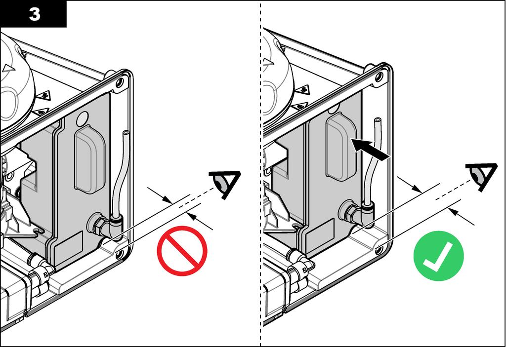
21 Plumbing Plumb the instrument W A R N I N G Explosion hazard. Make sure that the drain tube is free of all obstructions. If the drain tube has a blockage or is pinched or bent, high pressure can build up in the instrument. W A R N I N G Personal injury hazard. The sample line contains water under high water pressure that can burn skin if hot. Qualified personnel must remove the water pressure and wear personal protective equipment during this procedure. N O T I C E Do not let water get in the vial compartment or instrument damage will occur. Before the process head is installed on the instrument, make sure that there are no water leaks. Make sure that all tubing is fully seated. Make sure that the vial nut is tight. N O T I C E Before the instrument is plumbed, make sure that the desiccant cartridge and vial are installed. Items supplied by the user: Flow shutoff valve Tubing 6 Tubing cutter 1. Plumb the instrument. Refer to the illustrated steps that follow and Figure 6. Note: To plumb the instrument with accessories, refer to the documentation supplied with the accessories. 2. If a service bracket is not installed near the instrument, do the steps that follow: a. Do not do illustrated steps 1 and 2. b. Do illustrated steps 3 and 4 with the process head on the instrument. c. Before step 5, remove the process head from the instrument. d. Hold the process head so that it is not above the instrument or put the process head on the optional process head holder. e. Do illustrated steps 5 and 6. f. When there are no leaks from the process head or the flow regulator, install the process head on the instrument (illustrated step 8). 6 Refer to Specifications on page 3 for the tubing requirements. English 19


22 Figure 6 Plumbing overview no accessories 1 Service bracket 4 Flow regulator 2 Sample inlet 5 Flow shutoff valve 3 Sample outlet 20 English


23 Set the flow rate 1. Measure the flow with the flow regulator fully open. Make sure that the flow is in the middle of the flow specification. Refer to Specifications on page Slowly close the flow regulator until the flow decreases by 20 to 30%. Note: The flow regulator causes back pressure in the tubing and decreases the quantity of bubbles that can form in the vial. English 21
24 User navigation Refer to the controller documentation for keypad description and navigation information. Operation Configure the instrument Select the location name, signal averaging, measurement units, resolution, bubble reject, logger interval, programmable button function and more. 1. Push menu. 2. Select SENSOR SETUP>TU5x00 sc>configure. 3. Select an option. Option LOCATION SIGNAL AVG MEAS UNITS RESOLUTION BUBBLE REJECT LOGGER INTERVAL CLEANING SET DEFAULTS BUTTON FUNCTION FLOW SENSOR Description Sets the name or location of the sample source. The name or location entered shows on the measurement screen (16 characters maximum, default: serial number). When enabled, the turbidity reading that shows on the controller display is an average of the values measured during the time interval selected. Options: 5 to 90 seconds (default: 30 seconds). Note: The manufacturer recommends that the Signal Average setting be set to 30 seconds or less because of the fast response of the instrument. Selects the measurement units that show on the controller display and that are recorded to the data log. TU5300 sc options: NTU, FNU, TE/F, EBC or FTU. TU5400 sc options: NTU, mntu, FNU, mfnu, TE/F, EBC, FTU or mftu. Default: FNU for TU5300 sc or mfnu for TU5400 sc. Selects the number of decimal places that show on the controller display. Options: or TU5300 sc default: TU5400 sc default: Sets the bubble reject to on (default) or off. When set to on, high turbidity readings caused by bubbles in the sample are not shown or saved to the data log. Sets the frequency that the turbidity reading is saved to the data log. Options: 5 or 30 seconds or 1, 2, 5, 10 (default), 15 or 30 minutes. Configures the optional automatic cleaning module settings. Refer to the documentation supplied with the automatic cleaning module to configure the CLEANING setting. This option only shows when CLEANING MODULE is set to ON. Sets the instrument settings to the factory defaults. Sets the function of the programmable button. Refer to Figure 1 on page 9. SERVICE When the button is pushed, changes the output mode to HOLD if the output mode is currently ACTIVE and changes the output mode to ACTIVE if the output mode is currently HOLD. LINK2SC When the button is pushed, makes a Link2SC job file. Refer to Compare measurements with Link2SC on page 24. OFF (default) Disables the button. In addition, when CLEANING MODULE is set to ON, the options that follow show. START WIPE When the button is pushed, start a wiper cleaning cycle. WIPER REPLACE When the button is pushed, puts the wiper in the position for wiper replacement. Enables or disables the flow signal to show on the measurement screen and the DIAG/TEST>SIGNALS screen. Enables or disables flow signal warnings and errors to occur. When the optional flow sensor is installed, set to ON (default: OFF). 22 English
25 Option CLEANING MODULE AUTO-CHECK Description Enables or disables the automatic cleaning module menu options. When the optional automatic cleaning module is installed, set to ON (default: OFF). When this option is set to ON, the START WIPE option shows in the main SENSOR SETUP menu. Sets the time interval and sensitivity of the automatic system check. This option only shows when the instrument has the automatic system check option. CHECK INTERVAL Sets the time interval between automatic system checks. The automatic system check examines the condition of the vial. If the condition of the vial is bad, a warning message shows on the controller display. Options: OFF, 1, 2 (default), 3, 6, 12 hours or 1 day. SENSITIVITY Sets the sensitivity of the automatic system check to the condition of the vial. Options: HIGH or LOW. Show instrument information Show instrument information and the instrument status to get diagnostic information. 1. Push menu. 2. Select SENSOR SETUP>TU5x00 sc>diag/test. 3. Select an option. Option SENSOR INFO SIGNALS COUNTERS MAINTENANCE Description Shows the sensor name, location, serial number, type (EPA or ISO), model number, software version and measurement device version. Shows real-time values for turbidity, flow rate 7, the humidity set point and the air system humidity and temperature. Shows the vial condition (condensation and clarity) and the vial status (installed or not installed). Shows the lid type installed (calibration lid or process head). Shows the total operational time of the instrument, remaining number of wiper cycles, date the vial was installed/replaced, date the vial was cleaned, date of calibration, date of verification, operational time of the desiccant, remaining desiccant life, operational time of the air pump and date factory service was done. Note: The counters are reset when menu-guided maintenance is done. Refer to the MAINTENANCE option that follows. Starts menu-guided maintenance to replace or clean the vial, replace the wiper or replace the desiccant cartridge. START WIPE Starts a wiper cleaning when the optional automatic cleaning module is installed. OUTPUT MODE Selects the output behaviour during maintenance (default: HOLD). FACTORY SERVICE For service use only. Compare process and laboratory measurements Compare process and laboratory measurements with RFID or Link2SC. Make sure that the process and lab instrument are calibrated with the same number of calibration points and with the same standards. Make sure that the calibrations are not expired. Collect a grab sample Collect a 100-mL sample (minimum) from the sample outlet tubing of the process instrument. Collect the sample in a clean glass bottle with a tight-fitting cap. Do not collect samples directly into a sample vial. 1. Rinse the glass bottle a minimum of three times with water from the sample outlet tubing of the process instrument. Let the bottle overflow with the sample. 2. Collect a 100-mL sample (minimum) in the glass bottle from the sample outlet tubing of the process instrument. 7 A value less than 0.1 shows if the optional flow sensor is not installed. English 23
26 3. Put the cap on the sample bottle. 4. Analyze the grab sample immediately with the laboratory instrument to prevent settling, bacteria growth and temperature changes. Compare measurements with RFID When the process instrument and laboratory instrument have the optional RFID module, compare process and laboratory measurements with RFID. Items to collect: TU5300 sc or TU5400 sc with the optional RFID module TU5200 with the optional RFID module TU5200 sample vials Glass sample bottle with a sample RFID sticker Operator RFID tag (optional) 1. At the process instrument, put the operator RFID tag (if available) near the RFID module. Refer to Figure 1 on page 9 for the location of the RFID module. 2. Put a sample RFID sticker on the sample bottle. 3. Collect a grab sample. Refer to Collect a grab sample on page At the process instrument, put the RFID sticker that is on the sample bottle near the RFID module. The instrument gives a sound signal. The status indicator light changes to blue. The turbidity reading, operator ID (if available), location of the process instrument and the date and time are recorded on the RFID sticker. 5. Move the grab sample bottle to the laboratory instrument. 6. On the TU5200, push Options>Reading Setup. 7. Push Bubble Reject, then set bubble reject to on. 8. If the grab sample is 1 NTU or less, push Reading>Minimum Mode, then select 60 seconds. Note: In minimum mode, readings are done continuously for 60 seconds when a measurement is done. The smallest reading within 60 seconds is saved to the data log. 9. At the laboratory instrument, put the operator RFID tag (if available) near the RFID module to log in. 10. Put the RFID sticker that is on the sample bottle near the RFID module. The instrument gives a sound signal. The turbidity reading from the process instrument shows on the display. 11. Prepare a grab sample vial. Refer to Prepare a sample vial in the TU5200 documentation. 12. Measure the turbidity of the grab sample with the laboratory instrument. Refer to the TU5200 documentation. If the difference between the process and laboratory measurements is not more than the selected acceptance range, "Measurement values match." shows on the display. Refer to the TU5200 documentation to select the acceptance range. If "Measurement values do not match." shows on the display, click the link to show the troubleshooting steps. 13. To show the compare log, push Options>Compare Log. Refer to the TU5200 documentation for more options. 14. To send the verification data to external devices that are connected to the instrument, push Options>Send Data. Refer to the TU5200 documentation for more options. Compare measurements with Link2SC When the process instrument and laboratory instrument do not have the optional RFID module, compare the process and laboratory measurements with Link2SC. 24 English
27 Items to collect: TU5300 sc or TU5400 sc TU5200 TU5200 sample vials SD card 8 (or a LAN connection at the SC controller 9 and the laboratory instrument 10 ) USB adapter for the SD card (if used) 1. Collect a grab sample. Refer to Collect a grab sample on page If the SC controller and laboratory instrument do not have a LAN connection, install the SD card in the SC controller. Refer to the SC controller documentation to install the SD card. 3. At the SC controller, make a Link2SC job file as follows: a. Push menu. b. Select LINK2SC>CREATE A NEW JOB>TU5x00 sc. The SC controller makes a Link2SC job file. The turbidity reading, operator ID (if available), location of the process instrument and the date and time are recorded to the job file. In addition, the temperature, calibration settings, bubble reject setting, vial clarity and desiccant cartridge life are recorded to the Link2SC job file. 4. Push OK, then YES. 5. Select JOB>LAB. The Link2SC job file is saved to the SD card (if available) or sent to the laboratory instrument (when the SC controller and laboratory instrument have a LAN connection). To see the Link2SC job files on the SD card, select JOBS FROM CARD. 6. If the SC controller and laboratory instrument do not have a LAN connection, complete the steps that follow. a. Remove the SD card from the SC controller. b. At the laboratory instrument, put the SD card in the USB adapter. Then put the USB adapter in a USB port type A on the laboratory instrument. 7. Move the grab sample bottle to the laboratory instrument. 8. On the TU5200, push Options>Reading Setup. 9. Push Bubble Reject, then set bubble reject to on. 10. If the grab sample is 1 NTU or less, push Reading>Minimum Mode, then select 60 seconds. Note: In minimum mode, readings are done continuously for 60 seconds when a measurement is done. The smallest reading within 60 seconds is saved to the data log. 11. At the laboratory instrument, push the LINK2SC to show the job list. 12. Select the latest Link2SC job file. The turbidity measurement from the process instrument shows on the right side of the display. 13. Prepare a grab sample vial. Refer to Prepare a sample vial in the TU5200 documentation. 14. Measure the turbidity of the grab sample with the laboratory instrument. Refer to the TU5200 documentation. If the difference between the process and laboratory measurements is not more than the selected acceptance range, "Measurement values match." shows on the display. Refer to to select the acceptance range. If "Measurement values do not match." shows on the display, click the link to show the troubleshooting steps. 8 Refer to the SC controller documentation for the SD card requirements. 9 Refer to the SC controller documentation to set up a LAN connection at the SC controller. 10 Refer to the TU5200 documentation to set up a LAN connection at the laboratory instrument. English 25
28 15. To show the compare log, push Options>Compare Log. Refer to the TU5200 documentation for more options. 16. To send the verification data to external devices that are connected to the instrument, push Options>Send Data. Refer to the TU5200 documentation for more options. Configure the Link2SC settings Select the acceptance range permitted when process and laboratory measurements are compared with Link2SC. 1. Push menu. 2. Select SENSOR SETUP>TU5x00 sc>link2sc. 3. Select an option. Option Description ACCEPT. UNIT Sets the units used to compare the process and laboratory measurements. Options: %, NTU or LAB. Select LAB when the acceptance range is supplied by the laboratory instrument. ACCEPT. RANGE Sets the maximum difference permitted between the process and laboratory measurements. Options: 1 to 50% (default: 10%). This option only shows when ACCEPT. UNIT is set to % or NTU. Calibration W A R N I N G Chemical exposure hazard. Obey laboratory safety procedures and wear all of the personal protective equipment appropriate to the chemicals that are handled. Refer to the current safety data sheets (MSDS/SDS) for safety protocols. The instrument is factory calibrated and the laser light source is stable. The manufacturer recommends that a calibration verification be done periodically to make sure that the system operates as intended. The manufacturer recommends calibration as local regulations require and after repairs or comprehensive maintenance work. Use the optional calibration lid and a vial(s) with a StablCal standard or Formazin standard to calibrate the instrument. As an alternative, use a syringe and StablCal standard or Formazin standard to calibrate the instrument. Configure the calibration settings Select the calibration curve, calibration interval, output behavior during calibration and more. 1. Push menu. 2. Select SENSOR SETUP>TU5x00 sc>calibration>setup. 3. Select an option. Option MENU GUIDED Description Sets menu-guided calibration to SEALED VIAL, SYRINGE or OFF (default). Calibration instructions show on the controller display during calibration when set to SEALED VIAL or SYRINGE. 26 English
29 Option CAL CURVE VER AFTER CAL CAL REMINDER OUTPUT MODE CAL POINTS VALUES OFFSET 11 FACTOR 11 SET FACT CAL Description Selects the type of standard and the calibration curve (range). STABLCAL 0 40 FNU (default) 1-point calibration (20 FNU) with StablCal. STABLCAL FNU 2-point calibration (20 FNU and 600 FNU) with StablCal. FORMAZIN 0 40 FNU 2-point calibration (20 FNU and dilution water) with Formazin. FORMAZIN FNU 3-point calibration (20 FNU and 600 FNU and dilution water) with Formazin. CUSTOM 2- to 6-point calibration (0.02 to 1000 FNU) with StablCal or Formazin. The user selects the number of calibration points and the value of each calibration point. Sets the instrument to start a verification immediately after the instrument is calibrated. When set to on, the verification standard is measured immediately after a calibration is done. Default: ON. Sets the time interval between calibrations. The controller will show a reminder when a calibration is due. When a calibration is done, the calibration time is set to zero. Options: OFF(default), 1 day, 7 days, 30 days or 90 days. Selects the output behavior during calibration. ACTIVE-The outputs continues to agree with the operating conditions. HOLD (default)-keeps the outputs at the last known value when communication is lost. SET TRANSFER-Sets the outputs to the Set Transfer value selected in the controller settings. When the CAL CURVE setting is set to CUSTOM, this option sets the number of calibration points (2 to 6). This option only shows when the CAL CURVE setting is set to CUSTOM. Selects the value of each custom calibration point (0 to 700 NTU). This option only shows when the CAL CURVE setting is set to CUSTOM. Enables the offset function when set to on (default: OFF). When enabled, the selected offset value is added to each reading. To enter an offset value, set to ON then push back to exit the SETUP menu. Select OFFSET and enter an offset value (default: 0.0). Enables the factor function when set to on (default: OFF). When enabled, the selected factor value is used as a slope to the turbidity reading. To enter a factor value, set to ON then push back to exit the SETUP menu. Select FACTOR and enter a factor value (default: 1.0). Sets the calibration settings to the factory defaults. Calibrate with a syringe Pre-requisite: Configure the calibration settings. Refer to Configure the calibration settings on page 26. W A R N I N G Chemical exposure hazard. Obey laboratory safety procedures and wear all of the personal protective equipment appropriate to the chemicals that are handled. Refer to the current safety data sheets (MSDS/SDS) for safety protocols. Items to collect: StablCal standard or prepared Formazin standard at the same ambient temperature as the sensor Calibration syringe and tubing 11 This option is only available on ISO models of the instrument. This option only shows when the CAL CURVE setting is set to STABLCAL or FORMAZIN. English 27
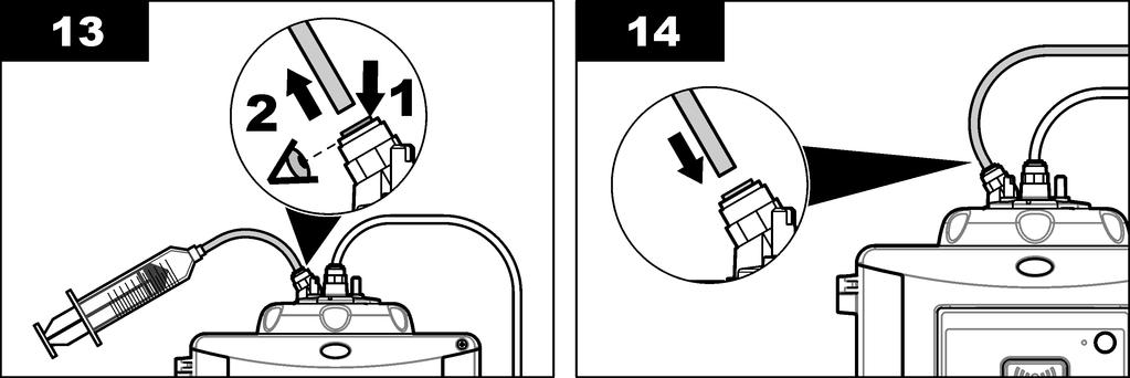
30 To prepare a Formazin standard(s), refer to Prepare Formazin standards on page 30. To make 4000-NTU Formazin stock solution, refer to Make 4000-NTU Formazin stock solution on page Push menu. 2. Select SENSOR SETUP>TU5x00 sc>calibration>setup>menu GUIDED>SYRINGE. 3. Select SENSOR SETUP>TU5x00 sc>calibration>start. 4. Complete the steps shown on the display. Refer to the illustrated steps that follow to complete the steps shown on the display. At illustrated step 4, enter the measured turbidity value of the standard. If the standard value that shows on the display is correct, push confirm. The status indicator light changes to blue. At illustrated step 15, fully open the flow regulator. Then slowly close the flow regulator until the flow decreases by 20 to 30%. 28 English
31 English 29
32 Make 4000-NTU Formazin stock solution W A R N I N G Chemical exposure hazard. Obey laboratory safety procedures and wear all of the personal protective equipment appropriate to the chemicals that are handled. Refer to the current safety data sheets (MSDS/SDS) for safety protocols. Note: The manufacturer recommends that Formazin stock solution is not made from raw materials. Preparation of Formazin stock solution is temperature and technique sensitive. Use Hach Formazin stock solution to get the best instrument performance and analytical standard accuracy. 1. Dissolve grams of reagent grade hydrazine sulfate ((NH 2 ) 2 H 2 SO 4 ) in about 400 ml of demineralized water. 2. Dissolve grams of reagent grade hexamethylenetetramine in approximately 400 ml of demineralized water. 3. Quantitatively, pour the two solutions in a 1-liter volumetric flask, and dilute to volume with demineralized water. Mix fully. 4. Let the solution stand for 48 hours at 25 ± 1 C (77 ± 1 F). Prepare Formazin standards Prepare Formazin standards immediately before a calibration and discard after use. 1. Prepare a 20 NTU Formazin standard as follows: a. Use a pipet to add 5.0 ml of 4000 NTU Formazin standard solution in a 1-L volumetric flask. b. Dilute to the mark with deionized water or distilled water with a turbidity of less than 0.5 NTU. Put in the stopper and mix well. 2. When the sample turbidity range is 40 to 700 NTU 12, prepare a 600 NTU Formazin standard as follows: a. Use a pipet to add 15.0 ml of 4000 NTU Formazin standard solution in a 100-mL volumetric flask. b. Dilute to the mark with deionized water or distilled water with a turbidity of less than 0.5 NTU. Put in the stopper and mix well mntu = NTU 30 English
33 Calibrate with StablCal vials with RFID 1. Invert the 20 NTU StablCal vial for 2 to 3 minutes. Refer to the documentation supplied with the StablCal vials. 2. Clean and dry the vial with a no-lint cloth. Refer to Prevent vial contamination on page Put the vial in front of the RFID module. The status indicator light flashes blue. The instrument records the value, the lot number, the expiration date and the Certificate of Analysis information from the RFID vial to the data log. 4. Remove the process head (or the automatic cleaning module). 5. Put the vial in the vial compartment. 6. Install the calibration lid. Make sure that the calibration lid is in the closed position. 7. Push the button on the front of the instrument. 8. When the status indicator light flashes green, remove the calibration lid. 9. Push the button on the front of the instrument to accept the calibration value. 10. Remove the vial. 11. If the display shows 600 NTU (or 600 FNU), do steps 1 to 10 again with the 600 NTU StablCal vial. 12. When the value of the verification standard shows on the display, do steps 2 to 10 again to measure the verification standard. English 31
34 13. Install the process head (or the automatic cleaning module). Prevent vial contamination N O T I C E Do not to touch or scratch the glass of the sample vial. Contamination or scratches on the glass can cause measurement errors. The glass must stay clean and have no scratches. Use a no-lint cloth to remove dirt, fingerprints or particles from the glass. Replace the sample vial when the glass has scratches. Refer to Figure 7 to identify where not to touch the sample vial. Always keep the sample vials in the vial stand to prevent contamination on the bottom of the vial. Figure 7 Sample vial overview 1 Measurement surface Do not touch. Calibrate with vials without RFID Prepare the standard vial(s) C A U T I O N Chemical exposure hazard. Dispose of chemicals and wastes in accordance with local, regional and national regulations. N O T I C E Always put a cap on the sample vial to prevent spills in the vial compartment. To use sealed vials for calibration, immediately go to Calibration procedure vials without RFID on page 34. To use unsealed vials for calibration, prepare the standard vial(s) as follows: 32 English
. Refer to the illustrated steps that follow.")
 calibration Three vials: formazin 20 NTU, formazin, 600 NTU and the dilution water 13 used to prepare the formazin standards STABLCAL 0-40 NTU (or 0 40 FNU)")
35 1. For formazin calibration, prepare the formazin standards with 4000-NTU formazin stock solution. Refer to Prepare Formazin standards on page 30. Note: To make 4000-NTU formazin stock solution, refer to Make 4000-NTU Formazin stock solution on page Prepare the standard vial(s). Refer to the illustrated steps that follow. FORMAZIN 0 40 NTU (or 0 40 FNU) calibration Two vials: formazin 20 NTU and dilution water 13 used to prepare the formazin standard. FORMAZIN NTU (or FNU) calibration Three vials: formazin 20 NTU, formazin, 600 NTU and the dilution water 13 used to prepare the formazin standards STABLCAL 0-40 NTU (or 0 40 FNU) calibration One vial: StablCal 20 NTU STABLCAL NTU (or FNU) calibration Two vials: StablCal 20 NTU and StablCal 600 NTU Make sure that the standard is at the same ambient temperature as the sensor. If there is contamination in the sample vial after it is rinsed with the sample, clean the sample vial. Refer to the TU5200 documentation for vial cleaning instructions. 13 Make sure that the vial contains dilution water for a minimum of 12 hours before the procedure. English 33

36 Prepare Formazin standards Prepare Formazin standards immediately before a calibration and discard after use. 1. Prepare a 20 NTU Formazin standard as follows: a. Use a pipet to add 5.0 ml of 4000 NTU Formazin standard solution in a 1-L volumetric flask. b. Dilute to the mark with deionized water or distilled water with a turbidity of less than 0.5 NTU. Put in the stopper and mix well. 2. When the sample turbidity range is 40 to 700 NTU 14, prepare a 600 NTU Formazin standard as follows: a. Use a pipet to add 15.0 ml of 4000 NTU Formazin standard solution in a 100-mL volumetric flask. b. Dilute to the mark with deionized water or distilled water with a turbidity of less than 0.5 NTU. Put in the stopper and mix well. Calibration procedure vials without RFID 1. Push menu. Select SENSOR SETUP> TU5x00 sc> CALIBRATION> SETUP> MENU GUIDED> SEALED VIAL. 2. Select SENSOR SETUP> TU5x00 sc> CALIBRATION> START. The status indicator light changes to blue. 3. Read the controller display to identify which vial to put in the vial compartment. 4. Carefully invert the vial a minimum of three times. For StablCal vials, invert the 20 NTU StablCal vial for 2 to 3 minutes. Refer to the documentation supplied with the StablCal vials mntu = NTU 34 English
37 5. Clean and dry the vial with a no-lint cloth. Refer to Prevent vial contamination on page Remove the process head (or the automatic cleaning module). 7. Put the vial in the vial compartment. 8. Install the calibration lid. Make sure that the calibration lid is in the closed position. 9. If the standard value that shows on the display is not correct, enter the accurate turbidity value of the standard from the certificate of analysis. 10. Complete the steps that show on the controller display. 11. When the status indicator light changes to green, remove the calibration lid. 12. Remove the vial. If the standard value that shows on the display is correct, push enter. 13. Do steps 3 to 12 again until all of the standard vials are measured. 14. If the value of the verification standard shows on the display, do steps 4 to 12 again to measure the verification standard. 15. Install the process head (or the automatic cleaning module). Verification Use the optional calibration lid and a sealed-vial 10-NTU StablCal standard (or a StablCal 10 NTU standard and a syringe) to do a primary calibration verification. As an alternative, use the optional calibration lid and the optional glass verification rod (< 0.1 NTU) to do a secondary calibration verification. English 35
38 Configure the verification settings Measure the value of the verification standard. Set the acceptance range and measurement units for verification. Set the verification reminder and type of menu guided verification. Set the output behavior during verification. 1. Push menu. 2. Select SENSOR SETUP>VERIFICATION>SETUP. 3. Select an option. Option MENU GUIDED DEFINE STD VAL ACCEPT. UNIT ACCEPT. RANGE VERIF REMINDER OUTPUT MODE Description Sets menu-guided verification to SEALED VIAL, SYRINGE or OFF (default). Verification instructions show on the controller display during verification when set to SEALED VIAL or SYRINGE. Select SEALED VIAL for verification with the glass verification rod. Measures the verification standard. The results are recorded to the instrument. For the best results, measure the verification standard immediately after calibration. Sets the acceptance range for verification to a percentage (1 to 99%) or an NTU value (0.015 to NTU). Options: % or NTU (or mntu). Sets the maximum difference permitted between the recorded value of the verification standard and the measured value of the verification standard during verification. Options: 1 to 99% or to NTU. Sets the time interval between calibration verifications. The display will show a reminder when a verification is due. Options: OFF(default), 1 day, 7 days, 30 days or 90 days. When a verification is done, the verification time is set to zero. Sets the output behavior during verification. ACTIVE-The outputs continues to agree with the operating conditions. HOLD (default)-keeps the outputs at the last known value when communication is lost. SET TRANSFER-Sets the outputs to the Set Transfer value selected in the controller settings. Do a calibration verification with a syringe Pre-requisite: Configure the verification settings. Refer to Configure the verification settings on page 36. W A R N I N G Chemical exposure hazard. Obey laboratory safety procedures and wear all of the personal protective equipment appropriate to the chemicals that are handled. Refer to the current safety data sheets (MSDS/SDS) for safety protocols. Items to collect: StablCal 10 NTU standard at the same ambient temperature as the sensor Calibration syringe and tubing 1. Push menu. 2. Select SENSOR SETUP>TU5x00 sc>verification>setup>menu GUIDED>SYRINGE. 3. Select SENSOR SETUP>TU5x00 sc>verification>start. 4. Complete the steps shown on the display. Refer to the illustrated steps that follow to complete the steps shown on the display. At illustrated step 4, enter the measured turbidity value of the verification standard. If the verification standard value that shows on the display is correct, push confirm. The status indicator light changes to blue. 36 English

39 At illustrated step 15, fully open the flow regulator. Then slowly close the flow regulator until the flow decreases by 20 to 30%. English 37

40 38 English
 to do a secondary calibration verification. 1. Push menu.")
41 Do a calibration verification with a sealed vial or glass rod Use the optional calibration lid and a sealed-vial 10-NTU StablCal standard to do a primary calibration verification. As an alternative, use the optional calibration lid and the optional glass verification rod (< 0.1 NTU) to do a secondary calibration verification. 1. Push menu. Select SENSOR SETUP> TU5x00 sc> VERIFICATION> SETUP>MENU GUIDED> SEALED VIAL. 2. Select SENSOR SETUP> TU5x00 sc> VERIFICATION> START. 3. If the verification standard value that shows on the display is not correct, enter the accurate turbidity value of the verification standard from the certificate of analysis for the sealed-vial StablCal standard or from the last recorded value from the <0.1 NTU glass rod. If the verification standard value that shows on the display is correct, push confirm. The status indicator light changes to blue. 4. If the verification standard is a liquid standard, carefully invert the verification standard vial a minimum of three times. 5. Clean and dry the verification standard vial with a no-lint cloth. Refer to Prevent vial contamination on page Remove the process head (or the automatic cleaning module). 7. Put the vial in the vial compartment. 8. Install the calibration lid. Make sure that the calibration lid is in the closed position. English 39
42 9. Complete the steps that show on the controller display. 10. When the status indicator light changes to green, remove the calibration lid. 11. Remove the vial. 12. Install the process head (or the automatic cleaning module). Show the calibration or verification history To show the historical data for the last four calibrations, push menu and select SENSOR SETUP>TU5x00 sc>calibration>cal LOG. To show the historical data for the last four verifications, push menu and select SENSOR SETUP>TU5x00 sc>verification>verif LOG. Maintenance W A R N I N G Burn hazard. Obey safe handling protocols during contact with hot liquids. C A U T I O N Multiple hazards. Only qualified personnel must conduct the tasks described in this section of the document. C A U T I O N Personal injury hazard. Never remove covers from the instrument. This is a laser-based instrument and the user risks injury if exposed to the laser. C A U T I O N Personal injury hazard. Glass components can break. Handle with care to prevent cuts. N O T I C E Do not disassemble the instrument for maintenance. If the internal components must be cleaned or repaired, contact the manufacturer. N O T I C E Stop the sample flow to the instrument and let the instrument become cool before maintenance is done. To set the output behavior during maintenance, push menu and select SENSOR SETUP>TU5x00 sc>diag/test>maintenance>output MODE. 40 English
43 Maintenance schedule Table 3 shows the recommended schedule of maintenance tasks. Facility requirements and operating conditions may increase the frequency of some tasks. Table 3 Maintenance schedule Task 1 to 3 months 1 to 2 years As necessary Clean the vial on page 41 Note: The cleaning interval is dependent on the water quality. X Clean the vial compartment on page 43 X Replace the vial on page 43 Replace the desiccant cartridge on page 45 Note: The replacement interval is dependent on the ambient humidity, ambient temperature and sample temperature. X X 15 Replace the tubing on page 46 X Clean spills C A U T I O N Chemical exposure hazard. Dispose of chemicals and wastes in accordance with local, regional and national regulations. 1. Obey all facility safety protocols for spill control. 2. Discard the waste according to applicable regulations. Clean the instrument Clean the exterior of the instrument with a moist cloth and a mild soap solution and then wipe the instrument dry as necessary. Clean the vial W A R N I N G Chemical exposure hazard. Obey laboratory safety procedures and wear all of the personal protective equipment appropriate to the chemicals that are handled. Refer to the current safety data sheets (MSDS/SDS) for safety protocols. When the turbidity reading shows that there is contamination in the process vial or "VIAL CLARITY" shows on the controller display, clean the vial. 1. Push menu. 2. Select SENSOR SETUP>TU5x00 sc>diag/test>maintenance>vial CLEANING. 3. Complete the steps that show on the controller display. The date the vial was cleaned is automatically saved after the last screen shows. 4. If the optional automatic cleaning module is installed, push menu and select SETUP>TU5x00 sc>start WIPE to start the automatic cleaning process. 5. If the optional automatic cleaning module is not installed, clean the vial with the optional vial wiper if available. Refer to Clean the vial with the optional wiper on page Two years or as identified by instrument notification. English 41


44 6. If the turbidity readings do not go back to the original values, do the illustrated steps that follow to clean the vial. Note: Hold the output values of the SC controller as necessary before the illustrated steps are done. Refer to the SC controller documentation to hold the outputs. Clean the vial with the optional wiper N O T I C E Carefully remove most of the water in the vial. Carefully put the vial wiper into the process vial so that no water spills out. Clean the process vial with the optional vial wiper as shown in the illustrated steps that follow. 42 English


45 Clean the vial compartment Clean the vial compartment only when the compartment has contamination. Make sure that the tool to clean the vial compartment has a soft surface and does not damage the instrument. Table 4 shows the options on how to clean the vial compartment. Table 4 Cleaning options Contaminant Dust Liquid, oil Options Vial compartment wiper, micro fiber cloth, lint-free cloth Cloth, water and cleaning agent Replace the vial N O T I C E Keep water out of the vial compartment or instrument damage will occur. Before the automatic cleaning module is installed on the instrument, make sure that there are no water leaks. Make sure that all tubing is fully seated. Make sure that the vial nut is tight. N O T I C E Hold the automatic cleaning module vertically when it is installed on the instrument or the vial can break. If the vial breaks, water will get in the vial compartment and instrument damage will occur. N O T I C E Do not to touch or scratch the glass of the process vial. Contamination or scratches on the glass can cause measurement errors. Note: Make sure that no particles fall into the vial compartment. English 43


46 1. Push menu. 2. Select SENSOR SETUP>DIAG/TEST>MAINTENANCE>VIAL REPLACEMENT. 3. Complete the steps that show on the controller display. The date the vial was replaced is automatically saved after the last screen shows. Refer to the illustrated steps that follow to replace the vial. To protect the new vial from contamination, use the vial replacement tool to install the vial. At illustrated step 3, put the process head on its side on a flat surface if a service bracket is not installed near the instrument. 44 English


47 Replace the desiccant cartridge The controller display will show when a desiccant cartridge replacement is due. Refer to the documentation included in the desiccant cartridge bag to replace the desiccant cartridge. English 45
48 Replace the tubing Replace the tubing when the tubing has a blockage or has damage. Turn the flow shutoff valve to stop flow to the instrument. Then refer to Plumb the instrument on page 19 to replace the tubing. Troubleshooting More troubleshooting information is available online. Go to then click Support to go to Hach Support Online. Reminders Reminders show on the controller display. To see all of the reminders, push menu then select DIAGNOSTICS>TU5x00 sc>reminder. Message Description Solution DRYER RANGE The desiccant cartridge capacity is low. Replace the desiccant cartridge. Refer to the documentation supplied with the desiccant cartridge. PERFORM CAL A calibration is due. Do a calibration. Refer to Calibration on page 26. PERFORM VER A verification is due. Do a verification. Refer to Verification on page 35. WIPER REPLACE A wiper replacement is due in the automatic cleaning module. Replace the wiper in the automatic cleaning module. Refer to the documentation supplied with the automatic cleaning module to replace the wiper. Warnings Warnings show on the controller display. To see all of the active warnings, push menu then select DIAGNOSTICS>TU5x00 sc>warning LIST. Warning Description Solution DRYER The drying circuit has a malfunction. Contact technical support. Measurements with limited validity are still available. CLEANING MODULE DESICCANT OLD The automatic cleaning module does not operate correctly. The desiccant cartridge is more than 2 years old. Make sure that the wiper head is installed correctly and the wiper arm can move up and down. Replace the desiccant cartridge. Refer to the documentation supplied with the desiccant cartridge. DRYER EXHAUS'D The desiccant cartridge life is zero. Replace the desiccant cartridge. Refer to the documentation supplied with the desiccant cartridge. HIGH FLOW HUM PCB SC LASER-TEMP HIGH LASER-TEMP SENS LOW FLOW The flow rate is higher than the limit (more than 1250 ml/min). There is humidity on the interior electronics of the instrument. The laser temperature is higher than the limit. The laser temperature sensor has a malfunction. The flow rate is lower than the limit (less than 75 ml/min). Adjust the flow regulator as necessary. Make sure that the flow regulator does not have a malfunction. Contact technical support. Measurements with limited validity are still available. Decrease the environmental temperature of the instrument. Contact technical support. Measurements with limited validity are still available. Examine the tubing for blockages that decrease the flow rate. Remove the blockages. Adjust the flow regulator as necessary. Make sure that the flow regulator does not have a malfunction. 46 English
49 Warning Description Solution NO FLOW The flow rate is less than 10 ml/min. Examine the tubing for blockages stop the flow. Remove the blockages. NOT DRYING PUMP SENS.DRY: FUNC SENS.DRY: HUM SENS.DRY: TEMP TURB TOO HIGH WIPER REPLACE The instrument cannot regulate the internal humidity. The air pump for the drying circuit has a malfunction. The air system of the drying system has a malfunction. The humidity value from the air sensor is not correct. The temperature value from the air sensor is not correct. The turbidity reading is not within the calibration range. A wiper replacement is due in the automatic cleaning module. Replace the desiccant cartridge. Refer to Replace the desiccant cartridge on page 45. If the error continues, contact technical support. Measurements with limited validity are still available. Contact technical support. Measurements with limited validity are still available. Contact technical support. Measurements with limited validity are still available. Contact technical support. Measurements with limited validity are still available. Contact technical support. Measurements with limited validity are still available. Make sure that the calibration range selected is applicable to the turbidity value of the sample. Replace the wiper in the automatic cleaning module. Refer to the documentation supplied with the automatic cleaning module to replace the wiper. VIAL CLARITY The vial or vial compartment is dirty. Clean or dry the vial and the vial compartment. Errors Errors show on the controller display. To see all of the active errors, push menu then select DIAGNOSTICS>TU5x00 sc>error LIST. Error Description Solution AU COMM An internal communication error occurred. Set the controller power to off and then on again. Contact technical support. AUTOCHK. NO FUNC CLEANING MODULE EE RSRVD ERR FLASH FAIL The automatic system check does not complete. The automatic cleaning module has a malfunction. There is a problem with the internal memory. The internal calibration memory is corrupted. Contact technical support. Contact technical support. Contact technical support. Contact technical support. HUMIDITY PCB There is humidity or water in the instrument. Contact technical support. LASER TOO LOW The laser has a malfunction. Contact technical support. MEAS ELECTRONIC PROC HEAD OPEN TURB TOO HIGH There is a measurement error. There is a problem in the electronics unit. The process head is in the open position or the process head detector has a malfunction. The turbidity reading is higher than the measurement range of the instrument (1000 FNU maximum). Contact technical support. Turn the process head to the closed position. Make sure that the turbidity value of the sample is within the measurement range of the instrument. English 47
50 Error Description Solution VIAL PRESENT There is no vial in the vial compartment. Install a vial in the vial compartment. VIAL CLARITY The vial or vial compartment is dirty. Clean or dry the vial and the vial compartment. WATER INGRESS There is water in the instrument. Immediately stop flow to the instrument. Disconnect the sensor cable. Contact technical support. Replacement parts and accessories W A R N I N G The desiccant cartridge can become hot. Only touch and remove the desiccant cartridge when it is at room temperature. Personal injury hazard. Use of non-approved parts may cause personal injury, damage to the instrument or equipment malfunction. The replacement parts in this section are approved by the manufacturer. Note: Product and Article numbers may vary for some selling regions. Contact the appropriate distributor or refer to the company website for contact information. Recommended standards Description Quantity Item no. Verification standard, < 0.1 NTU, glass verification rod (solid secondary standard) each LZY901 StablCal 800 mntu Standard 1 L StablCal 10 NTU Standard 500 ml StablCal 20 NTU Standard 1 L StablCal 20-NTU sealed vial with RFID each LZY837 StablCal 20-NTU sealed vial without RFID each LZY899 StablCal kit, sealed vials with RFID, includes: 10, 20 and 600 NTU vials StablCal kit, sealed vials without RFID, includes: 10, 20 and 600 NTU vials each each LZY835 LZY898 Replacement parts Description Quantity Item no. Cleaning lid screws and washers, hot water, includes: Cleaning lid screws (3x) and washers (3x) 3 LZY905 Desiccant cartridge each LZY876 Mounting set, includes: Mounting screws (4x), tubing clip screws (2x) and tubing clips (2x) each LZY870 Nut, process vial each LZY917 Seal, automatic cleaning module each LZY914 Seal, process head each LZV969 Seal, process vial each LZY English
51 Replacement parts (continued) Description Quantity Item no. Service bracket each LZY873 Flow regulator kit, includes: flow regulator and tube ¼-in. OD 0.13 m (5.11 in.) each LZY963 Vial with no seal, process each LZY834 Vial replacement tool each LZY906 Wall mount bracket kit, includes: Wall mount bracket (two tubing clips on bracket), mounting screws (4x), tubing clips (2x) and tubing clip screws (2x) each LZY871 Accessories Description Quantity Item no. Automatic cleaning module each LQV Bubble trap each LZY Calibration lid each LZY Extension cable, sensor cable, 1 m (3.3 ft) each Extension cable, sensor cable, 5 m (16.40 ft) each LZX848 Extension cable, sensor cable, 10 m (32.81 ft) each LZX849 Flow sensor kit, includes: flow sensor, flow sensor cap, mounting screws and 1 m (3.3 ft) of ¼ in. OD tubing Maintenance kit for post-filter applications, includes: Case, calibration lid, micro fiber cloth, 20 NTU StablCal sealed vial, verification glass rod, vial wiper, vial compartment wiper, mobile service bracket, glass verification rod ( 0.1 NTU) and vial replacement tool each each LQV LZY907 Micro fiber cloth, vial cleaning each LZY945 Process head holder each LZY946 RFID tags, operator 2/pkg LZQ066 RFID stickers, black 16 3/pkg LZQ067 Syringe with tubing, calibration and verification each LZY953 Tubing adapter, ¼ in. to 6 mm each LZY954 Tubing, bubble trap to TU5x00 sc, ¼ in. OD 1 m LZQ134 Tubing set, ULTRATURB replacement each LZY912 Tubing, inlet of bubble trap, 3/8 in. OD 4 m LZY947 Tubing, inlet and outlet of TU5x00 sc, ¼ in. OD 4 m LZY911 Vial wiper each LZY903 Vial compartment wiper each LZY Other colors are available. English 49
52 50 English
53
 2 11 52 88-320 Fax +49 (0) 2 11 52 88-210 info-de@hach.com www.de.hach.com HACH LANGE Sàrl 6, route de Compois 1222 Vésenaz SWITZERLAND Tel.")
54 *DOC * HACH COMPANY World Headquarters P.O. Box 389, Loveland, CO U.S.A. Tel. (970) (800) (U.S.A. only) Fax (970) HACH LANGE GMBH Willstätterstraße 11 D Düsseldorf, Germany Tel. +49 (0) Fax +49 (0) info-de@hach.com HACH LANGE Sàrl 6, route de Compois 1222 Vésenaz SWITZERLAND Tel Fax Hach Company/Hach Lange GmbH, All rights reserved.
DOC TU5300 sc/tu5400 sc. 03/2017, Edition 4. Basic User Manual
 DOC023.53.90501 TU5300 sc/tu5400 sc 03/2017, Edition 4 Basic User Manual Table of contents Specifications on page 3 Calibration on page 21 General information on page 4 Verification on page 21 Installation
User Manual Pocket Pro + Multi 1
 User Manual Pocket Pro + Multi 1 DOC022.53.80398 1 Specifications Specification Dimensions (W x D x H) Enclosure rating Weight Specifications are subject to change without notice. Details 37 x 30 x 170
Instruction Sheet. Calibration of Multiple 1720 and FT660 Turbidimeters
 Instruction Sheet 26596-89 Calibration of Multiple 1720 and FT660 Turbidimeters Overview This instruction sheet describes the calibration of up to eight 1720C, 1720D, or 1720E turbidimeters, or up to three
LDO II AQ 2/2014, Edition 1.5
 9623800 LDO II AQ 2/2014, Edition 1.5 USER MANUAL Table of Contents Specifications on page 2 General information on page 3 Product overview on page 4 Installation on page 5 Operation on page 7 Maintenance
ASE SOLVENT CONTROLLER INSTALLATION INSTRUCTIONS Dionex Corporation
 ASE SOLVENT CONTROLLER INSTALLATION INSTRUCTIONS 2000 Dionex Corporation Document No. 031277 Revision 03 April 2000 2000 Dionex Corporation All rights reserved worldwide. Printed in the United States of
Bante821 Portable Dissolved Oxygen Meter Instruction Manual
 Bante821 Portable Dissolved Oxygen Meter Instruction Manual BANTE INSTRUMENTS CO., LTD Bante821 Portable Dissolved Oxygen Meter 1 Introduction Thank you for selecting the Bante821 portable dissolved oxygen
Bante810 Benchtop Dissolved Oxygen Meter Instruction Manual
 Bante810 Benchtop Dissolved Oxygen Meter Instruction Manual BANTE INSTRUMENTS CO., LTD Bante810 Benchtop Dissolved Oxygen Meter 1 Introduction Thank you for selecting the Bante810 benchtop dissolved oxygen
RAM 4021-DPX Operation Manual
 RAM 4021-DPX Operation Manual Worldwide Manufacturer of Gas Detection Solutions TABLE OF CONTENTS ABL 4021-DPX / RAM 4021-DPX For Your Safety... 3 Description... 3 Setup Mode... 4 Lights/Alarms... 4 Operation...
Digital Melting Point Apparatus
 Digital Melting Point Apparatus Heating Plateau Ramping Start/Stop Plateau set Ramp stop Hold User Guide Version 1.1 Heating Viewing tube Sample Chamber IEC power inlet socket Power on/off Temperature
Bante820 Portable Dissolved Oxygen Meter Instruction Manual
 Bante820 Portable Dissolved Oxygen Meter Instruction Manual BANTE INSTRUMENTS CO., LTD Bante820 Portable Dissolved Oxygen Meter 1 Introduction Thank you for selecting the Bante820 portable dissolved oxygen
BGA158 Series CE Approved Class A Shutoff Gas Valve
 Installation Instructions BGA158 Issue Date August 24, 2011 BGA158 Series CE Approved Class A Shutoff Gas Valve Applications The BGA158 Series shutoff gas valve is an electrically operated gas valve that
SPECIFICATIONS PARTICLE SENSOR KS-18F Higashimotomachi, Kokubunji, Tokyo , Japan
 SPECIFICATIONS PARTICLE SENSOR KS-18F 3-20-41 Higashimotomachi, Kokubunji, Tokyo 185-8533, Japan No. 05083-5E 18-01 Printed in Japan Outline The KS-18F is a sensor which uses the light scattering method
G92 Series BASOTROL Automatic Pilot Gas Valve
 Installation Instructions Issue Date September 17, 2008 G92 Series BASOTROL Automatic Pilot Gas Valve Installation IMPORTANT: Only qualified personnel should install or service BASO Gas Products. These
SPECIFICATIONS PARTICLE SENSOR KS-19F Higashimotomachi, Kokubunji, Tokyo , Japan
 SPECIFICATIONS PARTICLE SENSOR KS-19F 3-20-41 Higashimotomachi, Kokubunji, Tokyo 185-8533, Japan No. 13012-3E 17-06 Printed in Japan Outline The KS-19F is a sensor which uses the light scattering method
Dual Solenoid Gas Valve Installation
 Installation IMPORTANT: These instructions are intended as a guide for qualified personnel installing or servicing FLYNN Gas Products. Carefully follow all instructions in this bulletin and all instructions
RAM 4021 Operation Manual
 RAM 4021 Operation Manual Worldwide Manufacturer of Gas Detection Solutions TABLE OF CONTENTS RAM 4021 For your safety...3 Description...3 Set-up mode...4 Annunciator lights/alarms...4 Operation...5 Calibration...6
FireHawk M7 Interface Module Software Instructions OPERATION AND INSTRUCTIONS
 FireHawk M7 Interface Module Software Instructions OPERATION AND INSTRUCTIONS WARNING THE WARRANTIES MADE BY MSA WITH RESPECT TO THE PRODUCT ARE VOIDED IF THE PRODUCT IS NOT USED AND MAINTAINED IN ACCORDANCE
Armfield Distillation Column Operation Guidelines
 Armfield Distillation Column Operation Guidelines 11-2016 R.Cox Safety SAFETY GLASSES ARE REQUIRED WHEN OPERATING THE DISTILLATION COLUMN Wear gloves when mixing alcohol feedstock The column will become
BGA158 Series CE Approved Class B Shutoff Gas Valve
 Installation Instructions BGA158 Issue Date March 22, 2016 BGA158 Series CE Approved Class B Shutoff Gas Valve Applications The BGA158 Series shutoff gas valve is an electrically operated shutoff valve
SMART Oxygen Analyzer. User Manual
 SMART Oxygen Analyzer User Manual TABLE OF CONTENTS 1 WELCOME... 3 2 NITROXBUDDY2 OVERVIEW... 3 3 WARNINGS... 3 4 BEFORE FIRST USE... 3 5 QUICK GUIDE... 3 6 SETTINGS... 4 6.1 BUTTON... 4 6.2 DISPLAY...
BGA244 Binary Gas Analyzer
 Quick Start Guide Revision 1.0 Certification Warranty Service certifies that this product met its published specification at the time of shipment. This product is warranted against defects in materials
Welcome to the World of In-Home Gardening! Simple Steps to Get Your AeroGarden Up and Growing (No Tools Required)
") Quick Setup Guide Welcome to the World of In-Home Gardening! Simple Steps to Get Your AeroGarden Up and Growing (No Tools Required) Harvest Model number: 100690-BLK / GRY / WHT / RED Harvest 360 Model
Quick Setup Guide Welcome to the World of In-Home Gardening! Simple Steps to Get Your AeroGarden Up and Growing (No Tools Required) Harvest Model number: 100690-BLK / GRY / WHT / RED Harvest 360 Model
Pressure Automated Calibration Equipment
 GE Measurement & control Pressure Automated Calibration Equipment Safety Instructions and User Guide - K0447 PACE5000 PACE6000 K0447 Issue No. 9 1 10 1 PACE5000 1 2 3 4 5 PACE6000 2 6 7 8 3 4 5 6 7 8 9
RGC-IR Remote Gas Calibrator for IR400
 Remote Gas Calibrator for IR400 The information and technical data disclosed in this document may be used and disseminated only for the purposes and to the extent specifically authorized in writing by
RAM Operation Manual
 RAM 4021-1 Operation Manual Worldwide Manufacturer of Gas Detection Solutions TABLE OF CONTENTS RAM 4021-1 For Your Safety... 2 Description... 2 Setup Mode... 3 Lights/Alarms... 3 Operation... 4 Calibration...
RAM Operation Manual. Worldwide Manufacturer of Gas Detection Solutions
 RAM 4021 Operation Manual Worldwide Manufacturer of Gas Detection Solutions TABLE OF CONTENTS RAM 4021 For Your Safety... 2 Description.... 2 Setup Mode.... 2 Lights/Alarms.... 3 Operation.... 4 Calibration....
6900 Maintenance Instruction System Flush
 Equipment Required FA74005 Damper Drain Tube FA16005 Cover Removal Tool FA900005 Beaker 0.25 Litre FA900003 Solvent Cleaning Bottle FA940021 Syringe Polypropylene 50 ml as required FA999045 Gloves Latex
RAM 4021-PR. Operation Manual. Worldwide Manufacturer of Gas Detection Solutions
 RAM 4021-PR Operation Manual Worldwide Manufacturer of Gas Detection Solutions TABLE OF CONTENTS RAM 4021-PR For Your Safety... 2 Description.... 2 Setup Mode.... 2 Lights/Alarms.... 3 Operation.... 4
Resusci Anne Simulator
 EN Resusci Anne Simulator Important Product Information www.laerdal.com Cautions and Warnings A Caution identifies conditions, hazards, or unsafe practices that can result in minor personal injury or damage
SDX Submersible Depth Transmitter User Manual
 SDX Submersible Depth Transmitter User Manual July 2017 USER INFORMATION Stevens makes no warranty as to the information furnished in these instructions and the reader assumes all risk in the use thereof.
Norrsken Family Booklet
 Section 1: Introduction Low Energy Designs produce efficient and effective LED based lighting products for commercial, retail and industry purposes. Each product may contain specific details on its operation
RAM Operation Manual. Worldwide Manufacturer of Gas Detection Solutions
 RAM 4021 Operation Manual Worldwide Manufacturer of Gas Detection Solutions TABLE OF CONTENTS RAM 4021 For Your Safety... 2 Description.... 2 Setup Mode.... 2 Lights/Alarms.... 3 Operation.... 4 Calibration....
SDX Submersible Depth Transmitter User Manual
 SDX Submersible Depth Transmitter User Manual October 2007 USER INFORMATION Stevens makes no warranty as to the information furnished in these instructions and the reader assumes all risk in the use thereof.
User Manual. Quantos Automated Dosing Liquid Module
 User Manual Liquid Module 1 Safety Information 1.1 Definition of warnings and symbols Signal Words WARNING for a hazardous situation with medium risk, possibly resulting in severe injuries or death if
Digital Vacuum Regulator
 Temperature Control for Research and Industry Digital Vacuum Regulator User s Manual Model 300 INDEX SECTION PAGE 1. QUICK OPERATING INSTRUCTIONS........................... 3 Safety Notices.................................................
TR Electronic Pressure Regulator. User s Manual
 TR Electronic Pressure Regulator Page 2 of 13 Table of Contents Warnings, Cautions & Notices... 3 Factory Default Setting... 4 Quick Start Procedure... 5 Configuration Tab... 8 Setup Tab... 9 Internal
UsER manual for Watersens ph -REDOX
 UsER manual for Watersens -REDOX Cl 8 1 2 6 3 3 7 7 4 4 4 4 Parts List 1 Redox Probe 1 x 2 PH Probe 1 x 5 Tube Weight 2 x 6 Connection Valve 1 x chlorine 3 Chlorine and Pumps 2 x 7 Dosing Valve 2 x 5 5
BI-680 Online Dissolved Oxygen Controller Instruction Manual
 BI-680 Online Dissolved Oxygen Controller Instruction Manual BANTE INSTRUMENTS CO., LTD BI-680 Online Dissolved Oxygen Controller 1 Introduction Thank you for selecting the BI-680 online dissolved oxygen
Overview. Front Panel: Keypad and Display
 Overview The GA-200B is an analyzer that integrates a gas sampling system with sensors to measure and display the concentrations of oxygen and carbon dioxide in a sample as the percentage of a gas in the
Welcome to the World of In-Home Gardening! Simple Steps to Get Your AeroGarden Up and Growing (No Tools Required)
") Quick Setup Guide Welcome to the World of In-Home Gardening! Simple Steps to Get Your AeroGarden Up and Growing (No Tools Required) Harvest Elite Model number: 100691-PPL / BSS / PCP / PSG Harvest Elite
Quick Setup Guide Welcome to the World of In-Home Gardening! Simple Steps to Get Your AeroGarden Up and Growing (No Tools Required) Harvest Elite Model number: 100691-PPL / BSS / PCP / PSG Harvest Elite
Pneumatic high-pressure controller Model CPC7000
 Calibration technology Pneumatic high-pressure controller Model CPC7000 WIKA data sheet CT 27.63 Applications Healthcare and avionics industry Industry (laboratory, workshop and production) Transmitter
Instructions for Assembly, Installation, and Operation of the Gas Addition Kit Accessory with the CEM Discover Systems
 Corporation Issued: 5/09 P/N: 600104 Rev. 2 Instructions for Assembly, Installation, and Operation of the Gas Addition Kit Accessory with the CEM Discover Systems The Gas Addition Accessory permits the
H15 Series BASO 100% Shutoff, Automatic Pilot Valve
 Installation Instructions Issue Date February 22, 2013 H15 Series BASO 100% Shutoff, Automatic Pilot Application The H15 Series pilot valves provide safe lighting and complete shutoff of pilot and main
Installation, Operating & Maintenance Instructions. Variable leak valve with manual actuator. Series 590 DN 16 mm (I. D. ⅝") E
 E") Installation, Operating & Maintenance Instructions Variable leak valve with manual actuator DN 16 mm (I. D. ⅝") This manual is valid for the following product ordering numbers: 59024-. E01 -... Sample
Installation, Operating & Maintenance Instructions Variable leak valve with manual actuator DN 16 mm (I. D. ⅝") This manual is valid for the following product ordering numbers: 59024-. E01 -... Sample
Instruction Manual 742 5/1/2009. Eclipse Ratio Regulators ES Series Version 1
 Instruction Manual 742 5/1/2009 Eclipse Ratio Regulators ES Series Version 1 Copyright Copyright 1997 by Eclipse, Inc. All rights reserved worldwide. This publication is protected by federal regulation
QUICK START GUIDE TO DRINKING WATER MONITORING
 APPENDIX F QUICK START GUIDE TO DRINKING WATER MONITORING Introduction: This Quick Start guide is designed to allow users who are already familiar with the basic use of YSI 6-series sondes for surface
User s Guide Temperature Sensor Converter TSC-599
 User s Guide Temperature Sensor Converter TSC-599 ILX Lightwave Corporation 31950 Frontage Road Bozeman, MT, U.S.A. 59715 U.S. & Canada: 1-800-459-9459 International Inquiries: 406-556-2481 Fax 406-586-9405
Installation and Use Manual
 Installation and Use Manual EMASMB & LMASMB Surface Mount Bottle Filling Stations Model EMASMB IMPORTANT THIS IS AN INDOOR APPLICATION ONLY! ALL SERVICE TO BE PERFORMED BY AN AUTHORIZED SERVICE PERSONNEL.
In Vivo Scientific, LLC INSTRUCTION MANUAL
 CO 2 Controller In Vivo Scientific, LLC INSTRUCTION MANUAL CONTENTS CONTENTS...1 ABOUT THIS MANUAL...2 INTRODUCTION...2 Cautions and Warnings...2 Parts List...2 Unpacking...2 INSTRUMENT DESCRIPTION...3
Appendix D: SOP of INNOVA 1412 Photoacoustic Multi-Gas Monitor. Description and Principle of Operation
 Page 1 of 19 : SOP of INNOVA 1412 Photoacoustic Multi-Gas Monitor Description and Principle of Operation The photoacoustic multi-gas monitor (INNOVA 1412, Innova AirTech Instruments, Denmark) is a highly
Stirring Water Bath. Instruction Manual
 Stirring Water Bath Instruction Manual Catalog Nos. SWB-10L-1-110 / 220 SWB-10L-2-110 / 220 SWB-20L-1-110 / 220 SWB-20L-3-110 / 220 www.majorsci.com service@majorsci.com Version 01A October 20, 2009 Un
Peak Pressure Indicator MSI-3
 Peak Pressure Indicator MSI-3 Operating Instructions Cylinder Pressure Monitoring Digital Pressure Indicator DPI No installation Ready to use High quality sensor Large memory Easy handling Cost effective.com
ACV-10 Automatic Control Valve
 ACV-10 Automatic Control Valve Installation, Operation & Maintenance General: The Archer Instruments ACV-10 is a precision automatic feed rate control valve for use in vacuum systems feeding Chlorine,
Read this first. Zetasizer nano series Self installation and Quick start guide MRK825-02
 ! Read this first Zetasizer nano series Self installation and Quick start guide I N S T R U M E N T S MRK825-02 Zetasizer Nano series Self installation and Quick start guide MAN0383 Issue 1.1 July 2007
User's Manual. Heavy Duty Dissolved Oxygen Meter. Model
 User's Manual Heavy Duty Dissolved Oxygen Meter Model 407510 Introduction Congratulations on your purchase of Extech's Heavy Duty Dissolved Oxygen / Temperature Meter which simultaneously displays Dissolved
NB/NBR NITROGEN BOOSTER FOR AVIATION SERVICE
 NB/NBR NITROGEN BOOSTER FOR AVIATION SERVICE INSTALLATION, OPERATION & MAINTENANCE MANUAL INTERFACE DEVICES, INC. 230 Depot Road, Milford, CT 06460 Ph: (203) 878-4648, Fx: (203) 882-0885, E-mail: info@interfacedevices.com
BGA158, BGA171 and BGA110 Series Shutoff Gas Valve
 Installation Instructions BGA Series Issue Date October 3, 2017 BGA158, BGA171 and BGA110 Series Shutoff Gas Valve Applications The BGA Series shutoff gas valve is an electrically operated gas valve that
CSA Sample Draw Aspirator Adapter Operator s Manual
 30-0951-CSA Sample Draw Aspirator Adapter Operator s Manual Part Number: 71-0367 Revision: 0 Released: 4/30/15 www.rkiinstruments.com WARNING Read and understand this instruction manual before operating
Pegas 4000 MF Gas Mixer InstructionManual Columbus Instruments
 Pegas 4000 MF Gas Mixer InstructionManual Contents I Table of Contents Foreword Part I Introduction 1 2 1 System overview... 2 2 Specifications... 3 Part II Installation 4 1 Rear panel connections...
Dual-gas Oxygen and Carbon Monoxide SMART Analyzer User Manual
 Dual-gas Oxygen and Carbon Monoxide SMART Analyzer User Manual TABLE OF CONTENTS 1 WELCOME... 3 2 COOTWO OVERVIEW... 3 3 WARNINGS... 3 4 BEFORE FIRST USE... 3 5 QUICK GUIDE... 4 6 SETTINGS... 4 6.1 BUTTON...
Water Weir Flow Controller. Introduction. Safety Precautions. Mounting the Hardware
 57007-88 Introduction Safety Precautions This instruction sheet describes how to set up and use the Hach (Figure 1). A water weir is a device that raises or diverts water to regulate the flow. Hach s water
Instruction Sheet. Important Note: Information that requires special emphasis. Note: Information that supplements points in the main text.
 Hach LDO Sensor Instruction Sheet 00745589 Safety Precautions Please read this entire instruction sheet before operating this sensor. Pay particular attention to all danger and caution statements. Failure
OUS31. Technical Information
 Technical Information OUS Turbidity sensor Installation and immersion sensor for drinking water and industrial water according to the 90 scattered light method Application All phases of drinking water
OPERATING INSTRUCTIONS MANUAL FOR QACV PNEUMATIC DOSING PUMP
 This operating instructions contains safety information that if ignored can endanger life or result in serious injury. They are indicated by this icon. Use of this pump with radioactive chemicals is forbidden!
DOscan10 Pocket Dissolved Oxygen Tester Instruction Manual
 DOscan10 Pocket Dissolved Oxygen Tester Instruction Manual BANTE INSTRUMENTS CO., LTD DOscan10 Pocket Dissolved Oxygen Tester 1 Thank you for selecting the DOscan10 pocket dissolved oxygen tester. This
Instruction Manual. CG16K Barometrically Compensated Capsule Dial Gauge. CG16K Capsule Dial Gauge, 0 to 25 mbar
 Instruction Manual D356-10-880 Issue G Original CG16K Barometrically Compensated Capsule Dial Gauge Description CG16K Capsule Dial Gauge, 0 to 1040 mbar CG16K Capsule Dial Gauge, 0 to 125 mbar CG16K Capsule
AUTOMATIC TIRE INFLATOR # MW-60, MW-60-4WAY & MW-64HP
 USER MANUEL AUTOMATIC TIRE INFLATOR # MW-60, MW-60-4WAY & MW-64HP TIRE EQUIPMENT MANUFACTURER 1.866.409.RACK WWW.MARTINSINDUSTRIES.COM info@martinsindustries.com PARTS Verify that the following components
Troubleshooting Guide: 640 Pediatric Exam Table with Midmark Scale
 Troubleshooting Guide: 640 Pediatric Exam Table with Midmark Scale Contents Description Refer To: Scale Troubleshooting Chart Troubleshooting Error Codes Error Messages Adjustments / Repair Procedures
EC214 EC215 - EC215R Bench Conductivity Meters
 Instruction Manual EC214 EC215 - EC215R Bench Conductivity Meters http://www.hannainst.com These Instruments are in Compliance with the CE Directives Dear Customer, Thank you for choosing a Hanna Instruments
MP15 Jockey Pump Controller
 Setup and Operating Instructions MP15 Jockey Pump Controller This manual provides general information, installation, operation, maintenance, and system setup information for Metron Model MP15 Jockey Pump
SMART Carbon Monoxide Analyzer. User Manual
 SMART Carbon Monoxide Analyzer User Manual TABLE OF CONTENTS 1 WELCOME... 3 2 MONOX OVERVIEW... 3 3 WARNINGS... 3 4 BEFORE FIRST USE... 3 5 QUICK GUIDE... 3 6 SETTINGS... 4 6.1 BUTTON... 4 6.2 DISPLAY...
Calibration Requirements for Direct Reading Confined Space Gas Detectors
 : Calibration Requirements for Direct Reading Confined Space Gas Detectors However, the definition of bump test has always been a little slippery. Some manufacturers differentiate between a bump test that
92831 TEL: (714) FAX:
 FAX:") Document No. 1800-75 Respiration Test Chamber Copyright 2010 Terra Universal Inc. All rights reserved. Revised September 2010 Terra Universal, Inc. TerraUniversal.com 800 S. Raymond Ave. Fullerton, CA
Document No. 1800-75 Respiration Test Chamber Copyright 2010 Terra Universal Inc. All rights reserved. Revised September 2010 Terra Universal, Inc. TerraUniversal.com 800 S. Raymond Ave. Fullerton, CA
Sterisil Ac+ Installation & Operating Manual
 Sterisil Ac+ Installation & Operating Manual 719 622 7200 Sterisil.com Arbor Dental Associates 2 Table of Contents Introduction 4 Sterisil Ac + Features 5 Installation Instructions 6 Maintenance 10 Troubleshooting
Vapor Sorption Analyzer
 Vapor Sorption Analyzer Quick Start Guide 1. Getting Started Place the AquaLab VSA on a flat surface. Use the bubble level(figure 1: Adjustment and bubble level) and use the adjustable feet to level the
Operating Instructions Part No
 DIGITAL AUTOMATIC TYRE INFLATOR Operating Instructions Part No. 11.0578 Thank you for selecting this Jamec Pem Automatic Tyre Inflator. Please read this manual before carrying out any installation or service
Nothing's as cool, as a freshwater pool. easychem 770 ORP and ph Controller for Pools and Spas with Timer Output for Pool Pump
 Page 1 of 6 TPS Australia - Quality hand-made instruments since 1968. Nothing's as cool, as a freshwater pool easychem 770 ORP and ph Controller for Pools and Spas with Timer Output for Pool Pump Automatic
SPECIFICATIONS ATTENTION
 VPS 504 S06 Installation Manual - P/N 80122 - Ed. 01/09 VPS 504 S06 and S05 Valve Proving System Installation Instructions VPS 1 6 Gases Natural gas, air and other inert gases. NOT suitable for butane
Model GFC 7000T CO 2 Analyzer (Addendum to GFC 7000TA Manual, PN 07272)
") Manual Addendum Model GFC 7000T CO 2 Analyzer (Addendum to GFC 7000TA Manual, PN 07272) P/N M07273 DATE 06/11/13 TELEDYNE ELECTRONIC TECHNOLOGIES Analytical Instruments 16830 Chestnut Street City of Industry,
Manual Addendum Model GFC 7000T CO 2 Analyzer (Addendum to GFC 7000TA Manual, PN 07272) P/N M07273 DATE 06/11/13 TELEDYNE ELECTRONIC TECHNOLOGIES Analytical Instruments 16830 Chestnut Street City of Industry,
User Manual. Quantos Automated Dosing Powder Module
 User Manual Powder Module 1 Introduction Thank you for purchasing the Quantos dosing system. Quantos is based on the renowned and reliable XPE series balances from METTLER TOLEDO. Besides the highly accurate
Instruction Manual No. 742, 8/98
 Instruction Manual No. 742, 8/98 Eclipse Ratio Regulators ES Series COPYRIGHT Copyright I997 by Eclipse Combustion, Inc. All rights reserved worldwide. This publication is protected by federal regulation
INSTRUCTION MANUAL MP4AR Remote Convection Gauge Range: 1 x 10⁻³ Torr to 1 x 10+3 Torr
 INSTRUCTION MANUAL MP4AR Remote Convection Gauge Range: 1 x 10⁻³ Torr to 1 x 10+3 Torr A DIVISION OF THE FREDERICKS COMPANY 2400 PHILMONT AVE. HUNTINGDONVALLEY, PA 19006 PARTS LIST 1 3 4 2 # QTY ITEM DESCRIPTION
User Manual. Quantos Automated Dosing Liquid Module
 User Manual Quantos Automated Dosing Liquid Module Overview Liquid module 4 2 1 3 5 6 7 Legend Liquid Module Pump module with bottle Liquid kit with liquid dosing head 1 Pump module (QL2) 4 Top glass
User Manual PTW-DensiX. D / Di/Zi
 User Manual PTW-DensiX D148.131.0/3 2005-05 Di/Zi General Information General Information The product bears the CE-mark "CE-0124" in accordance with the Council Directive 93/42/EEC about Medical Devices
Type 3709 Pneumatic Lock-up Valve. Translation of original instructions. Mounting and Operating Instructions EB 8391 EN
 Type 3709 Pneumatic Lock-up Valve Translation of original instructions Mounting and Operating Instructions EB 8391 EN Edition July 2017 Note on these mounting and operating instructions These mounting
4 and 8 Station PDS Control Installation & Operators Manual
 4 and 8 Station PDS Control Installation & Operators Manual 1402-15 11/2000 June 2003 MW1402C Chore-Time Warranty 4 and 8 Station PDS Control Chore-Time Warranty Chore-Time Equipment ( Chore-Time ) warrants
Type Operating Instructions. 2/2-way solenoid valve 2/2-Wege Magnetventil Electrovanne 2/2 voies.
 2/2-way solenoid valve 2/2-Wege Magnetventil Electrovanne 2/2 voies We reserve the right to make technical changes without notice. Technische Änderungen vorbehalten. Sous réserve de modifications techniques.
Media-Isolated Mag Plus Probe Low Pressure-ISO Kit
 Manual No: 577013-975 Revision: B Media-Isolated Mag Plus Probe Low Pressure-ISO Kit Installation Guide Notice Veeder-Root makes no warranty of any kind with regard to this publication, including, but
Agilent 1290 Infinity Pump Head Maintenance
 Agilent 1290 Infinity Pump Head Maintenance Technical Note Agilent Technologies Notices Agilent Technologies, Inc. 2012-2015, 2016 No part of this manual may be reproduced in any form or by any means (including
D10S/D20S Wall/Post Mount Inflator Quick Start Manual
 PART NUMBER SERIAL NUMBER D10S/D20S Wall/Post Mount Inflator Quick Start Manual Please read and save these instructions. Read carefully before attempting to assemble, install, operate or maintain the product
ATEX, IECEx and MET (Class I, Division 1) Safety Instructions icam502
 Safety Instructions icam502") ATEX, IECEx and MET (Class I, Division 1) Safety Instructions icam502 This device complies with part 15 of the FCC Rules. Operation is subject to the following two conditions: (1) This device may not cause
ATEX, IECEx and MET (Class I, Division 1) Safety Instructions icam502 This device complies with part 15 of the FCC Rules. Operation is subject to the following two conditions: (1) This device may not cause
Pneumatic high-pressure controller Model CPC7000
 Calibration technology Pneumatic high-pressure controller Model CPC7000 WIKA data sheet CT 27.63 Applications Automotive and avionics industry Industry (laboratory, workshop and production) Transmitter
HUMOR 20. High-precision Humidity Calibrator HUMOR 20. Operation
 High-precision Humidity Calibrator The role of humidity calibrations that are accurate, reproducible, and documentable is becoming more and more important. ISO quality guidelines and regulations according
WELCOME TO THE REVOLUTION
 USER GUIDE WELCOME TO THE REVOLUTION THANK YOU FOR CHOOSING THE GCQUAD We listened to what you wanted - and created the most accurate, versatile and game-enhancing ball and club analysis solution available
PitchTracker User Guide. Model: DKPT01 User Guide
 PitchTracker User Guide Model: DKPT01 User Guide PACKAGE CONTENTS What Comes in the Box USING YOUR SMART BALL Turn On Your Smart Ball Pair your Smart Ball Turn Off Your Smart Ball Charge your Smart Ball
5000TOC Sensor Standard Operating Procedure for TOC Calibration Conductivity Calibration Temperature Calibration Flow Rate Calibration
 Part No. 84468 5000TOC Sensor Standard Operating Procedure for TOC Calibration Conductivity Calibration Temperature Calibration Flow Rate Calibration This document contains proprietary information, which
Operating Instructions. Ball valve fitting according to ZB For pressure transmitter VEGABAR 82. Document ID: 50027
 Operating Instructions Ball valve fitting according to ZB 2553 For pressure transmitter VEGABAR 82 Document ID: 50027 Contents Contents 1 About this document 1.1 Function... 3 1.2 Target group... 3 1.3
ATS430 turbidity sensor Retractable insertion assembly
 A MEASUREMENT & ANALYTICS INSTRUCTION ATS430 turbidity sensor Retractable insertion assembly Measurement made easy 1 Introduction This publication details installation procedures for the retractable insertion
Pressure Injection Cell Operator s Manual
 Pressure Injection Cell Operator s Manual Operator s Manual Pressure Injection Cell CONGRATULATIONS! Congratulations on your purchase of a Next Advance Pressure Injection Cell. Please read this operator
Dextens Thermo Conductivity Sensors. Type 52101, 54101, 55101
 Dextens Thermo Conductivity Sensors Type 52101, 54101, 55101 Operating Manual May 2012 Table of Content 1 GENERAL INFORMATION...4 1.1 DISCLAIMER...4 1.2 SYMBOLS AND CONVENTIONS...4 1.3 SERVICES AND REPAIRS...4