DOC TU5300 sc/tu5400 sc. 03/2017, Edition 4. Basic User Manual
|
|
|
- Merryl Payne
- 5 years ago
- Views:
Transcription
1 DOC TU5300 sc/tu5400 sc 03/2017, Edition 4 Basic User Manual
2
3 Table of contents Specifications on page 3 Calibration on page 21 General information on page 4 Verification on page 21 Installation on page 10 Maintenance on page 21 User navigation on page 20 Troubleshooting on page 27 Operation on page 20 Additional information An expanded user manual is available on the manufacturer's website. Videos on how to install, operate and do maintenance and troubleshooting on the TU5300 sc and the TU5400 sc turbidimeters are available on the TU5 Series Turbidimeters playlist at Specifications Specifications are subject to change without notice. Specification Measurement method Primary compliance method Enclosure Dimensions (W x D x H) Weight Power requirements Protection class Details Nephelometry with scattered light collected at a 90-degree angle to the incident light and 360 degrees around the sample vial EPA approved Hach Method Material: ASA Luran S 777K / RAL7000, TPE RESIN Elastocon STK40, Thermoplastic Elastomer TPS-SEBS (60 Shore) and stainless steel 268 x 249 x 190 mm (10.6 x 9.8 x 7.5 in.) Instrument with the process head: 2.7 kg (6.0 lb); Instrument with the optional automatic cleaning module: 5.0 kg (11.0 lb) 12 VDC, 14 VA supplied by the SC controller III Pollution degree 2 Installation category Mounting Operating temperature Storage temperature Humidity II Indoor on a wall 0 to 50 C (32 to 122 F) 40 to 60 C ( 40 to 140 F) 5 to 95% relative humidity, non-condensing Sensor cable length 1.6 m (5.25 ft) 2 Laser Optical light source Fittings Class 2 laser product: Contains a non user-serviceable class 2 laser. 650 nm, maximum 0.43 mw Sample inlet and outlet: ¼-in. OD tubing Extension cables are available. The maximum sensor cable length is 50 m (164 ft) when no accessories are connected to the instrument. English 3
4 Specification Tubing requirements Measurement units Range Method detection limit Response time Accuracy Details Polyethylene, polyamide or polyurethane tubing. Calibrated ¼ in. OD, or 0.1 mm ( or in.) TU5300 sc: NTU, FNU, TE/F, EBC or FTU; TU5400 sc: NTU, mntu 3, FNU, mfnu, TE/F, EBC, FTU or mftu. 0 to 700 NTU, FNU, TE/F and FTU; 0 to 175 EBC TU5300 sc: NTU at 25 C (77 F) ( < NTU range); TU5400 sc: NTU at 25 C (77 F) ( < NTU range) T90 < 30 seconds at 100 ml/min ± 2% or ± 0.01 NTU (the larger value) from 0 to 40 NTU ± 10% of reading from 40 to 700 NTU based on Formazin primary standard at 25 C (77 F) Linearity Better than 1% for 0 to 40 NTU based on Formazin primary standard at 25 C (77 F). Repeatability Stray light Resolution Air bubble compensation Sample requirements Calibration options Verification options Verification (RFID or Link2SC ) Certifications Warranty TU5300 sc: NTU or 1% (the larger value) at 25 C (77 F) ( > NTU range); TU5400 sc: NTU or 1% (the larger value) at 25 C (77 F) ( > NTU range) < 0.01 NTU NTU ( to /1.000 to 9.999/10.00 to 99.99/100.0 to 700 NTU) Default: TU5300 sc: NTU and TU5400 sc: NTU Physical, mathematical Temperature: 2 to 60 C (35.6 to 140 F) Conductivity: 3000 µs/cm maximum at 25 C (77 F) Flow rate 4 : 100 to 1000 ml/min; optimal flow rate: 200 to 500 ml/min Pressure: 6 bar (87 psi) maximum compared to air, 2 to 40 C (35.6 to 104 F) sample; 3 bar (43.5 psi) maximum compared to air, 40 to 60 C (104 to 140 F) sample StablCal or Formazin: 1-point calibration (20 NTU) for 0 to 40 NTU measurement range, 2-point calibration (20 and 600 NTU) for 0 to 700 NTU (full) measurement range or 2- to 6-point custom calibration for a measurement range of 0 NTU to the highest calibration point. Glass verification rod (solid secondary standard) 0.1 NTU, StablCal or Formazin Verification of the measurement value by comparison of the process and lab measurements with RFID or Link2SC. CE compliant; US FDA accession number: xxx. This product complies with IEC/EN and to 21 CFR in accordance with Laser Notice No. 50. Australian RCM. 1 year (EU: 2 years) General information In no event will the manufacturer be liable for direct, indirect, special, incidental or consequential damages resulting from any defect or omission in this manual. The manufacturer reserves the right to 3 1 mntu = NTU 4 For the best results, operate the instrument at a flow rate of 200 ml/min when the maximum particle size is 20 µm. For larger particles (150 µm maximum), the best flow rate is 350 to 500 ml/min. 4 English
5 make changes in this manual and the products it describes at any time, without notice or obligation. Revised editions are found on the manufacturer s website. Safety information N O T I C E The manufacturer is not responsible for any damages due to misapplication or misuse of this product including, without limitation, direct, incidental and consequential damages, and disclaims such damages to the full extent permitted under applicable law. The user is solely responsible to identify critical application risks and install appropriate mechanisms to protect processes during a possible equipment malfunction. Please read this entire manual before unpacking, setting up or operating this equipment. Pay attention to all danger and caution statements. Failure to do so could result in serious injury to the operator or damage to the equipment. Make sure that the protection provided by this equipment is not impaired. Do not use or install this equipment in any manner other than that specified in this manual. Use of hazard information D A N G E R Indicates a potentially or imminently hazardous situation which, if not avoided, will result in death or serious injury. W A R N I N G Indicates a potentially or imminently hazardous situation which, if not avoided, could result in death or serious injury. C A U T I O N Indicates a potentially hazardous situation that may result in minor or moderate injury. N O T I C E Indicates a situation which, if not avoided, may cause damage to the instrument. Information that requires special emphasis. Precautionary labels Read all labels and tags attached to the instrument. Personal injury or damage to the instrument could occur if not observed. A symbol on the instrument is referenced in the manual with a precautionary statement. Electrical equipment marked with this symbol may not be disposed of in European domestic or public disposal systems. Return old or end-of-life equipment to the manufacturer for disposal at no charge to the user. This symbol, if noted on the instrument, references the instruction manual for operation and/or safety information. This symbol indicates the need for protective eye wear. This symbol indicates a laser device is used in the equipment. English 5


6 This symbol indicates that the marked item can be hot and should not be touched without care. This symbol identifies a risk of chemical harm and indicates that only individuals qualified and trained to work with chemicals should handle chemicals or perform maintenance on chemical delivery systems associated with the equipment. This symbol indicates radio waves. Class 2 laser product D A N G E R Personal injury hazard. Never remove covers from the instrument. This is a laser-based instrument and the user risks injury if exposed to the laser. Class 2 laser product, IEC :2014, 650 nm, maximum 0.43 mw Location: Rear of the instrument. Conforms to U.S. regulations 21 CFR and in accordance with Laser Notice No. 50. Location: Rear of the instrument. Caution Class 2 laser radiation when the lid is open. Do not look into the laser beam. Location: Top of the vial compartment. This instrument is a Class 2 Laser product. There is only visible laser radiation when the instrument is defective and when the instrument lid is open. This product complies with EN , "Safety Requirements for Electrical Equipment for Measurement, Control and Laboratory Use" and with IEC/EN , "Safety of Laser Products" and with 21 CFR in accordance with Laser Notice No. 50. Refer to the labels on the instrument that supply laser information. RFID module Instruments with the optional RFID module receive and transmit information and data. The RFID module operates with a frequency of MHz. RFID technology is a radio application. Radio applications are subject to national conditions of authorization. The use of instruments with the optional RFID module is currently permitted in the regions that follow: EU (European Union) countries, EFTA (European Free Trade Association) countries, Turkey, Serbia, Macedonia, Australia, Canada, US, Chile, Ecuador, Venezuela, Mexico, Brazil, South Africa, India, Singapore, Argentina, Columbia, Peru and Panama 6 English
7 The use of instruments with the optional RFID module outside of the above-mentioned regions can violate national laws. The manufacturer reserves the right also to get authorization in other countries. In case of doubt, contact the manufacturer. Safety information for RFID modules W A R N I N G Multiple hazards. Do not disassemble the instrument for maintenance. If the internal components must be cleaned or repaired, contact the manufacturer. W A R N I N G Electromagnetic radiation hazard. Do not use the instrument in dangerous environments. N O T I C E This instrument is sensitive to electromagnetic and electromechanical interference. These interferences can have an effect on the analysis performance of this instrument. Do not put this instrument near equipment that can cause interference. Obey the safety information that follows to operate the instrument in accordance with local, regional and national requirements. Do not operate the instrument in hospitals and equivalent establishments or near medical equipment, such as pace makers or hearing aids. Do not operate the instrument near highly flammable substances, such as fuels, highly flammable chemicals and explosives. Do not operate the instrument near combustible gases, vapors or dust. Keep the instrument away from strong vibration or shock. The instrument can cause interference in immediate proximity to televisions, radios and computers. The warranty does not cover improper use or wear. FCC conformance for RFID This instrument may contain a registered radio frequency identification device (RFID). Refer to Table 1 for the Federal Communications Commission (FCC) registration information. Table 1 Registration information Parameter FCC identification number (FCC ID) IC Frequency Value YCB-ZBA A-ZBA MHz Certification Canadian Radio Interference-Causing Equipment Regulation, IECS-003, Class A: Supporting test records reside with the manufacturer. This Class A digital apparatus meets all requirements of the Canadian Interference-Causing Equipment Regulations. Cet appareil numérique de classe A répond à toutes les exigences de la réglementation canadienne sur les équipements provoquant des interférences. FCC Part 15, Class "A" Limits Supporting test records reside with the manufacturer. The device complies with Part 15 of the FCC Rules. Operation is subject to the following conditions: English 7
8 1. The equipment may not cause harmful interference. 2. The equipment must accept any interference received, including interference that may cause undesired operation. Changes or modifications to this equipment not expressly approved by the party responsible for compliance could void the user's authority to operate the equipment. This equipment has been tested and found to comply with the limits for a Class A digital device, pursuant to Part 15 of the FCC rules. These limits are designed to provide reasonable protection against harmful interference when the equipment is operated in a commercial environment. This equipment generates, uses and can radiate radio frequency energy and, if not installed and used in accordance with the instruction manual, may cause harmful interference to radio communications. Operation of this equipment in a residential area is likely to cause harmful interference, in which case the user will be required to correct the interference at their expense. The following techniques can be used to reduce interference problems: 1. Disconnect the equipment from its power source to verify that it is or is not the source of the interference. 2. If the equipment is connected to the same outlet as the device experiencing interference, connect the equipment to a different outlet. 3. Move the equipment away from the device receiving the interference. 4. Reposition the receiving antenna for the device receiving the interference. 5. Try combinations of the above. Product overview D A N G E R Chemical or biological hazards. If this instrument is used to monitor a treatment process and/or chemical feed system for which there are regulatory limits and monitoring requirements related to public health, public safety, food or beverage manufacture or processing, it is the responsibility of the user of this instrument to know and abide by any applicable regulation and to have sufficient and appropriate mechanisms in place for compliance with applicable regulations in the event of malfunction of the instrument. The TU5300 sc and the TU5400 sc turbidimeters are used with an SC controller to measure lowrange turbidity mostly in finished drinking water applications. Refer to Figure 1. The TU5300 sc and the TU5400 sc turbidimeters measure scattered light at an angle of 90 in a 360 radius around the axis of the incident light beam. An optional RFID module and an automatic system check option are available 5. The RFID module is shown in Figure 1. The RFID module lets process and laboratory turbidity measurements be easily compared. A description of the automatic system check option is given in the expanded user manual on the manufacturer's website. PROGNOSYS predictive diagnostic software is available for the TU5300 sc and TU5400 sc turbidimeters. To use PROGNOSYS, connect the turbidimeter to an SC controller with PROGNOSYS. Videos on how to install, operate and do maintenance and troubleshooting on the TU5300 sc and the TU5400 sc turbidimeters are available on the TU5 Series Turbidimeters playlist at For the accessories, refer to the expanded user manual on the manufacturer's website. 5 The RFID module and automatic system check option is only available at the time of purchase. 8 English
 5 Cleaning lid 12 Channels for cables 6 Sample inlet 13 Extension connector for accessories 7 Sample outlet 14 Sensor cable Product components Make sure that all components have")
9 Figure 1 Product overview 1 Programmable button 8 Process head 2 Status indicator light 6 9 Overflow drain 3 RFID module indicator (optional) 10 Process head (open) 4 Cleaning lid screws (3x) 11 Process head (closed) 5 Cleaning lid 12 Channels for cables 6 Sample inlet 13 Extension connector for accessories 7 Sample outlet 14 Sensor cable Product components Make sure that all components have been received. Refer to Figure 2. If any items are missing or damaged, contact the manufacturer or a sales representative immediately. 6 Shows the instrument status. Refer to the expanded user manual on the manufacturer's website for more information. English 9
10 Figure 2 Product components 1 TU5300 sc or TU5400 sc 6 Cleaning lid screws and washers for hot water applications 2 Wall mount bracket (two tubing clips on bracket) 7 Vial replacement tool 3 Tubing clips 8 Flow regulator 4 Tubing clip screws, 2.2 x 6 mm 9 Service bracket 5 Mounting screws, 4 x 16 mm 10 Desiccant cartridge Installation C A U T I O N Multiple hazards. Only qualified personnel must conduct the tasks described in this section of the document. Installation guidelines N O T I C E Make sure that there is a floor drain near the instrument. Examine the instrument daily for leaks. This instrument is rated for an altitude of 3100 m (10,710 ft) maximum. Use of this instrument at an altitude higher than 3100 m can slightly increase the potential for the electrical insulation to break down, which can result in an electric shock hazard. The manufacturer recommends that users with concerns contact technical support. Installation overview Figure 3 shows the installation overview with no accessories and the clearances necessary. Refer to the expanded manual on the manufacturer's website for the system overview with all of the accessories. 10 English
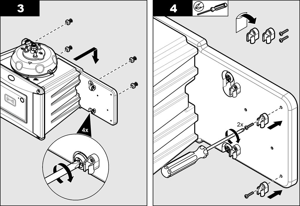
11 Figure 3 Installation overview with no accessories 1 Service bracket 5 Sample inlet 2 Process head 6 Sample outlet 3 SC controller 7 TU5300 sc or TU5400 sc 4 Flow regulator Wall mount Install the instrument on a wall in a vertical position. Install the instrument so that it is level. Install with the wall mount bracket Refer to the illustrated steps that follow to install the instrument on a wall with the wall mount bracket. The mounting hardware to install the wall mount bracket on a wall is supplied by the user. If a 1720D, 1720E, or FT660 instrument is replaced, remove the instrument from the wall. Then do steps 2 to 4 of the illustrated steps that follow to install the instrument on the existing hardware. Note: When the accessories are used, the installation location of the tubing clips is different. Refer to the documentation supplied with the accessories for tubing clip installation. English 11

12 12 English

13 Install directly on a wall As an alternative, refer to the illustrated steps that follow to install the instrument directly on a wall. The mounting hardware is supplied by the user. Remove the thin, plastic film from the mounting holes on the back of the instrument. Install the desiccant cartridge N O T I C E Make sure that the desiccant cartridge is installed or damage to the instrument will occur. For initial installation, complete the steps below. For replacement, refer to the documentation supplied with the desiccant cartridge. 1. Look at the install by date on the packaging. Refer to Figure 4. Do not use if the current date is past the install by date. 2. Make sure that the indicator on the new desiccant cartridge is blue. Refer to Figure Install the new desiccant cartridge. Refer to the illustrated steps that follow. English 13

")
14 Figure 4 Examine the desiccant cartridge 1 Install by date (mm.yyyy = month and year) 2 Indicator (blue = not expired, pink = expired) 14 English


15 English 15
, the cleaning lid screws will become hot.")
 when it is not installed on the instrument.")
16 Replace the cleaning lid screws N O T I C E Do not overtighten the screws or breakage will occur. Hand tighten the screws. If the sample temperature is 40 to 60 C (104 to 140 F), the cleaning lid screws will become hot. To prevent burns, replace the standard cleaning lid screws with the cleaning lid screws and washers for hot water. Refer to Figure 1 on page 9 for the location of the cleaning lid screws. Install the service bracket The service bracket holds the process head (or the optional automatic cleaning module) when it is not installed on the instrument. Refer to Installation overview on page 10 to install the service bracket the correct distance from the instrument. Refer to the illustrated steps that follow to install the service bracket. Install the flow sensor (optional) The optional flow sensor identifies if the sample flow is within specifications. A warning shows on the controller display and the status indicator light when a no flow, low flow or high flow warning occurs. Install the optional flow sensor. Refer to the documentation supplied with the optional flow sensor. Install the automatic cleaning module (optional) The automatic cleaning module cleans the inside of the process vial at a selected time interval. Install the optional automatic cleaning module. Refer to the documentation supplied with the automatic cleaning module. Connect to an SC controller C A U T I O N Personal injury hazard. Do not look into the vial compartment when the instrument is connected to power. 16 English

17 1. Install the latest software version on the SC controller before the instrument is connected to the SC controller. Get the latest software version from Refer to the software installation instructions supplied in the box or supplied in the software download for the SC controller. 2. Remove power to the SC controller. 3. Connect the sensor cable to the quick-connect fitting of the SC controller. Refer to Figure 5. Keep the connector cap for later use. 4. Supply power to the SC controller. The SC controller looks for the instrument. 5. When the SC controller finds the instrument, push enter. On the main screen, the controller shows the turbidity value measured by the turbidimeter. Figure 5 Connect the sensor cable to the SC controller Plumbing Plumb the instrument W A R N I N G Explosion hazard. Make sure that the drain tube is free of all obstructions. If the drain tube has a blockage or is pinched or bent, high pressure can build up in the instrument. W A R N I N G Personal injury hazard. The sample line contains water under high water pressure that can burn skin if hot. Qualified personnel must remove the water pressure and wear personal protective equipment during this procedure. N O T I C E Do not let water get in the vial compartment or instrument damage will occur. Before the process head is installed on the instrument, make sure that there are no water leaks. Make sure that all tubing is fully seated. Make sure that the vial nut is tight. N O T I C E Before the instrument is plumbed, make sure that the desiccant cartridge and vial are installed. Items supplied by the user: Flow shutoff valve English 17
18 Tubing 7 Tubing cutter 1. Plumb the instrument. Refer to the illustrated steps that follow and Figure 6. Note: To plumb the instrument with accessories, refer to the documentation supplied with the accessories. 2. If a service bracket is not installed near the instrument, do the steps that follow: a. Do not do illustrated steps 1 and 2. b. Do illustrated steps 3 and 4 with the process head on the instrument. c. Before step 5, remove the process head from the instrument. d. Hold the process head so that it is not above the instrument or put the process head on the optional process head holder. e. Do illustrated steps 5 and 6. f. When there are no leaks from the process head or the flow regulator, install the process head on the instrument (illustrated step 8). Figure 6 Plumbing overview no accessories 1 Service bracket 4 Flow regulator 2 Sample inlet 5 Flow shutoff valve 3 Sample outlet 7 Refer to Specifications on page 3 for the tubing requirements. 18 English


19 English 19


20 Set the flow rate 1. Measure the flow with the flow regulator fully open. Make sure that the flow is in the middle of the flow specification. Refer to Specifications on page Slowly close the flow regulator until the flow decreases by 20 to 30%. Note: The flow regulator causes back pressure in the tubing and decreases the quantity of bubbles that can form in the vial. User navigation Refer to the controller documentation for keypad description and navigation information. Operation Refer to the expanded user manual on the manufacturer's website to configure the instrument settings and to compare process and lab measurements. 20 English
21 Calibration W A R N I N G Chemical exposure hazard. Obey laboratory safety procedures and wear all of the personal protective equipment appropriate to the chemicals that are handled. Refer to the current safety data sheets (MSDS/SDS) for safety protocols. When the instrument is used for US EPA regulatory reporting, calibrations must be done according to US EPA guidance documents and methodologies. Contact local regulating authorities for additional compliance regulations. The instrument is factory calibrated and the laser light source is stable. The manufacturer recommends that a calibration verification be done periodically to make sure that the system operates as intended. The manufacturer recommends calibration as local regulations require and after repairs or comprehensive maintenance work. Use the optional calibration lid and a vial(s) with a StablCal standard or Formazin standard to calibrate the instrument. As an alternative, use a syringe and StablCal standard or Formazin standard to calibrate the instrument. Refer to the expanded user manual on to calibrate the instrument and configure the calibration settings. Verification Use the optional calibration lid and a sealed-vial 10-NTU StablCal standard (or a StablCal 10 NTU standard and a syringe) to do a primary calibration verification. As an alternative, use the optional calibration lid and the optional glass verification rod (< 0.1 NTU) to do a secondary calibration verification. Do a calibration verification immediately after each calibration to measure the verification standard and record the measured value to the instrument. Do calibration verifications between calibrations according to the regulatory recommendations to identify if the instrument operates correctly and is calibrated. When a calibration verification is done between calibrations, the verification standard is measured. The measured value is compared to the recorded value of the verification standard. Refer to the expanded user manual on to do a verification and configure the verification settings. Maintenance W A R N I N G Burn hazard. Obey safe handling protocols during contact with hot liquids. C A U T I O N Multiple hazards. Only qualified personnel must conduct the tasks described in this section of the document. C A U T I O N Personal injury hazard. Never remove covers from the instrument. This is a laser-based instrument and the user risks injury if exposed to the laser. English 21
22 C A U T I O N Personal injury hazard. Glass components can break. Handle with care to prevent cuts. N O T I C E Do not disassemble the instrument for maintenance. If the internal components must be cleaned or repaired, contact the manufacturer. N O T I C E Stop the sample flow to the instrument and let the instrument become cool before maintenance is done. To set the output behavior during maintenance, push menu and select SENSOR SETUP>TU5x00 sc>diag/test>maintenance>output MODE. Maintenance schedule Table 2 shows the recommended schedule of maintenance tasks. Facility requirements and operating conditions may increase the frequency of some tasks. Table 2 Maintenance schedule Task 1 to 3 months 1 to 2 years As necessary Clean the vial on page 23 Note: The cleaning interval is dependent on the water quality. X Clean the vial compartment on page 24 X Replace the vial on page 25 Replace the desiccant cartridge on page 27 Note: The replacement interval is dependent on the ambient humidity, ambient temperature and sample temperature. X X 8 Replace the tubing on page 27 X Clean spills C A U T I O N Chemical exposure hazard. Dispose of chemicals and wastes in accordance with local, regional and national regulations. 1. Obey all facility safety protocols for spill control. 2. Discard the waste according to applicable regulations. Clean the instrument Do not use solvents to clean the instrument. N O T I C E The instrument is maintenance free. Regular cleaning is not necessary for normal operation. If the exterior of the instrument becomes dirty, wipe the instrument surfaces with a clean, moist cloth. 8 Two years or as identified by instrument notification. 22 English
 for safety protocols.")

23 Clean the vial W A R N I N G Chemical exposure hazard. Obey laboratory safety procedures and wear all of the personal protective equipment appropriate to the chemicals that are handled. Refer to the current safety data sheets (MSDS/SDS) for safety protocols. When the turbidity reading shows that there is contamination in the process vial or "VIAL CLARITY" shows on the controller display, clean the vial. 1. Push menu. 2. Select SENSOR SETUP>TU5x00 sc>diag/test>maintenance>vial CLEANING. 3. Complete the steps that show on the controller display. The date the vial was cleaned is automatically saved after the last screen shows. 4. If the optional automatic cleaning module is installed, push menu and select SETUP>TU5x00 sc>start WIPE to start the automatic cleaning process. 5. If the optional automatic cleaning module is not installed, clean the vial with the optional vial wiper if available. Refer to Clean the vial with the optional wiper on page If the turbidity readings do not go back to the original values, do the illustrated steps that follow to clean the vial. Note: Hold the output values of the SC controller as necessary before the illustrated steps are done. Refer to the SC controller documentation to hold the outputs. English 23


24 Clean the vial with the optional wiper N O T I C E Carefully remove most of the water in the vial. Carefully put the vial wiper into the process vial so that no water spills out. Clean the process vial with the optional vial wiper as shown in the illustrated steps that follow. Clean the vial compartment Clean the vial compartment only when the compartment has contamination. Make sure that the tool to clean the vial compartment has a soft surface and does not damage the instrument. Table 3 shows the options on how to clean the vial compartment. 24 English
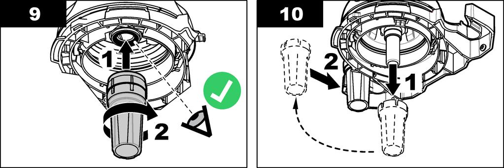
25 Table 3 Cleaning options Contaminant Dust Liquid, oil Options Vial compartment wiper, micro fiber cloth, lint-free cloth Cloth, water and cleaning agent Replace the vial N O T I C E Keep water out of the vial compartment or instrument damage will occur. Before the automatic cleaning module is installed on the instrument, make sure that there are no water leaks. Make sure that all tubing is fully seated. Make sure that the vial nut is tight. N O T I C E Hold the automatic cleaning module vertically when it is installed on the instrument or the vial can break. If the vial breaks, water will get in the vial compartment and instrument damage will occur. N O T I C E Do not to touch or scratch the glass of the process vial. Contamination or scratches on the glass can cause measurement errors. Note: Make sure that no particles fall into the vial compartment. 1. Push menu. 2. Select SENSOR SETUP>DIAG/TEST>MAINTENANCE>VIAL REPLACEMENT. 3. Complete the steps that show on the controller display. The date the vial was replaced is automatically saved after the last screen shows. Refer to the illustrated steps that follow to replace the vial. To protect the new vial from contamination, use the vial replacement tool to install the vial. At illustrated step 3, put the process head on its side on a flat surface if a service bracket is not installed near the instrument. English 25


26 26 English


27 Replace the desiccant cartridge The controller display will show when a desiccant cartridge replacement is due. Refer to the documentation included in the desiccant cartridge bag to replace the desiccant cartridge. Replace the tubing Replace the tubing when the tubing has a blockage or has damage. Turn the flow shutoff valve to stop flow to the instrument. Then refer to Plumb the instrument on page 17 to replace the tubing. Troubleshooting Refer to the expanded user manual on for troubleshooting information. English 27
28 28 English
29
 2 11 52 88-320 Fax +49 (0) 2 11 52 88-210 info-de@hach.com www.de.hach.com HACH LANGE Sàrl 6, route de Compois 1222 Vésenaz SWITZERLAND Tel.")
30 *DOC * HACH COMPANY World Headquarters P.O. Box 389, Loveland, CO U.S.A. Tel. (970) (800) (U.S.A. only) Fax (970) HACH LANGE GMBH Willstätterstraße 11 D Düsseldorf, Germany Tel. +49 (0) Fax +49 (0) info-de@hach.com HACH LANGE Sàrl 6, route de Compois 1222 Vésenaz SWITZERLAND Tel Fax Hach Company/Hach Lange GmbH, All rights reserved. Printed in Germany.
DOC TU5300 sc/tu5400 sc. 03/2017, Edition 4. User Manual
 DOC343.53.90477 TU5300 sc/tu5400 sc 03/2017, Edition 4 User Manual Table of Contents Specifications... 3 General information... 4 Safety information... 4 Use of hazard information... 5 Precautionary labels...
User Manual Pocket Pro + Multi 1
 User Manual Pocket Pro + Multi 1 DOC022.53.80398 1 Specifications Specification Dimensions (W x D x H) Enclosure rating Weight Specifications are subject to change without notice. Details 37 x 30 x 170
LDO II AQ 2/2014, Edition 1.5
 9623800 LDO II AQ 2/2014, Edition 1.5 USER MANUAL Table of Contents Specifications on page 2 General information on page 3 Product overview on page 4 Installation on page 5 Operation on page 7 Maintenance
ASE SOLVENT CONTROLLER INSTALLATION INSTRUCTIONS Dionex Corporation
 ASE SOLVENT CONTROLLER INSTALLATION INSTRUCTIONS 2000 Dionex Corporation Document No. 031277 Revision 03 April 2000 2000 Dionex Corporation All rights reserved worldwide. Printed in the United States of
Instruction Sheet. Calibration of Multiple 1720 and FT660 Turbidimeters
 Instruction Sheet 26596-89 Calibration of Multiple 1720 and FT660 Turbidimeters Overview This instruction sheet describes the calibration of up to eight 1720C, 1720D, or 1720E turbidimeters, or up to three
Digital Melting Point Apparatus
 Digital Melting Point Apparatus Heating Plateau Ramping Start/Stop Plateau set Ramp stop Hold User Guide Version 1.1 Heating Viewing tube Sample Chamber IEC power inlet socket Power on/off Temperature
Resusci Anne Simulator
 EN Resusci Anne Simulator Important Product Information www.laerdal.com Cautions and Warnings A Caution identifies conditions, hazards, or unsafe practices that can result in minor personal injury or damage
Norrsken Family Booklet
 Section 1: Introduction Low Energy Designs produce efficient and effective LED based lighting products for commercial, retail and industry purposes. Each product may contain specific details on its operation
BGA158 Series CE Approved Class A Shutoff Gas Valve
 Installation Instructions BGA158 Issue Date August 24, 2011 BGA158 Series CE Approved Class A Shutoff Gas Valve Applications The BGA158 Series shutoff gas valve is an electrically operated gas valve that
Fish Farming Water Quality Test Kit
 DOC326.97.00098 Fish Farming Water Quality Test Kit FF-1A (243002) 11/2017, Edition 1 User Manual Table of Contents General information... 3 Safety information... 3 Use of hazard information...3 Product
Dual Solenoid Gas Valve Installation
 Installation IMPORTANT: These instructions are intended as a guide for qualified personnel installing or servicing FLYNN Gas Products. Carefully follow all instructions in this bulletin and all instructions
SDX Submersible Depth Transmitter User Manual
 SDX Submersible Depth Transmitter User Manual July 2017 USER INFORMATION Stevens makes no warranty as to the information furnished in these instructions and the reader assumes all risk in the use thereof.
RGC-IR Remote Gas Calibrator for IR400
 Remote Gas Calibrator for IR400 The information and technical data disclosed in this document may be used and disseminated only for the purposes and to the extent specifically authorized in writing by
User Manual. Quantos Automated Dosing Liquid Module
 User Manual Liquid Module 1 Safety Information 1.1 Definition of warnings and symbols Signal Words WARNING for a hazardous situation with medium risk, possibly resulting in severe injuries or death if
G92 Series BASOTROL Automatic Pilot Gas Valve
 Installation Instructions Issue Date September 17, 2008 G92 Series BASOTROL Automatic Pilot Gas Valve Installation IMPORTANT: Only qualified personnel should install or service BASO Gas Products. These
Agilent 1290 Infinity Pump Head Maintenance
 Agilent 1290 Infinity Pump Head Maintenance Technical Note Agilent Technologies Notices Agilent Technologies, Inc. 2012-2015, 2016 No part of this manual may be reproduced in any form or by any means (including
USER MANUAL LTH-255A Hand Piece
 USER MANUAL LTH-255A Hand Piece 250 Corporate Blvd.,Suite B Newark, DE 19702, USA Tel 302-709-0408 Fax 302-709-0409 http://www.companiontherapylaser.com LBL000037C USER MANUAL LTH-255A Hand Piece DCN000049
SDX Submersible Depth Transmitter User Manual
 SDX Submersible Depth Transmitter User Manual October 2007 USER INFORMATION Stevens makes no warranty as to the information furnished in these instructions and the reader assumes all risk in the use thereof.
Installation, Operating & Maintenance Instructions. Variable leak valve with manual actuator. Series 590 DN 16 mm (I. D. ⅝") E
 E") Installation, Operating & Maintenance Instructions Variable leak valve with manual actuator DN 16 mm (I. D. ⅝") This manual is valid for the following product ordering numbers: 59024-. E01 -... Sample
Installation, Operating & Maintenance Instructions Variable leak valve with manual actuator DN 16 mm (I. D. ⅝") This manual is valid for the following product ordering numbers: 59024-. E01 -... Sample
BGA158 Series CE Approved Class B Shutoff Gas Valve
 Installation Instructions BGA158 Issue Date March 22, 2016 BGA158 Series CE Approved Class B Shutoff Gas Valve Applications The BGA158 Series shutoff gas valve is an electrically operated shutoff valve
Instruction Manual. CG16K Barometrically Compensated Capsule Dial Gauge. CG16K Capsule Dial Gauge, 0 to 25 mbar
 Instruction Manual D356-10-880 Issue G Original CG16K Barometrically Compensated Capsule Dial Gauge Description CG16K Capsule Dial Gauge, 0 to 1040 mbar CG16K Capsule Dial Gauge, 0 to 125 mbar CG16K Capsule
User Manual. Quantos Automated Dosing Liquid Module
 User Manual Quantos Automated Dosing Liquid Module Overview Liquid module 4 2 1 3 5 6 7 Legend Liquid Module Pump module with bottle Liquid kit with liquid dosing head 1 Pump module (QL2) 4 Top glass
Peak Pressure Indicator MSI-3
 Peak Pressure Indicator MSI-3 Operating Instructions Cylinder Pressure Monitoring Digital Pressure Indicator DPI No installation Ready to use High quality sensor Large memory Easy handling Cost effective.com
4 and 8 Station PDS Control Installation & Operators Manual
 4 and 8 Station PDS Control Installation & Operators Manual 1402-15 11/2000 June 2003 MW1402C Chore-Time Warranty 4 and 8 Station PDS Control Chore-Time Warranty Chore-Time Equipment ( Chore-Time ) warrants
Type 0404 / /2-way solenoid valve 2/2-Wege-Magnetventil Électrovanne 2/2 voies Operating Instructions Bedienungsanleitung Manuel d utilisation
 Type 0404 / 5404 2/2-way solenoid valve 2/2-Wege-Magnetventil Électrovanne 2/2 voies Operating Instructions Bedienungsanleitung Manuel d utilisation 1 OPERATING INSTRUCTIONS The operating instructions
User Manual PTW-DensiX. D / Di/Zi
 User Manual PTW-DensiX D148.131.0/3 2005-05 Di/Zi General Information General Information The product bears the CE-mark "CE-0124" in accordance with the Council Directive 93/42/EEC about Medical Devices
Instruction Manual 742 5/1/2009. Eclipse Ratio Regulators ES Series Version 1
 Instruction Manual 742 5/1/2009 Eclipse Ratio Regulators ES Series Version 1 Copyright Copyright 1997 by Eclipse, Inc. All rights reserved worldwide. This publication is protected by federal regulation
SDS -Series 4C-D201/-D202 Supplemental Drying System User s Manual
 SDS -Series 4C-D201/-D202 Supplemental Drying System User s Manual 8 Executive Drive P.O. Box 2105 Toms River, NJ 08754 (732) 244-0010 (800) 337-3762 fax (732) 244-8140 www.permapure.com info@permapure.com
U S E R M A N U A L CAUTION. SAVE THESE INSTRUCTIONS Federal (USA) law restricts this device to sale by or on the order of a physician.
 law restricts this device to sale by or on the order of a physician.") U S E R M A N U A L 1600 SERIES OXYGEN REGULATOR 168715G (Shown) SAVE THESE INSTRUCTIONS Federal (USA) law restricts this device to sale by or on the order of a physician. 300 Held Drive Tel: (+001) 610-262-6090
U S E R M A N U A L 1600 SERIES OXYGEN REGULATOR 168715G (Shown) SAVE THESE INSTRUCTIONS Federal (USA) law restricts this device to sale by or on the order of a physician. 300 Held Drive Tel: (+001) 610-262-6090
Refillable ORP/Redox Probe: Model MTC30101 or MTC30103
 User Manual Refillable ORP/Redox Probe: Model MTC30101 or MTC30103 DOC022.53.80026 Safety information Precautionary labels Read all labels and tags attached to the instrument. Personal injury or damage
SPECIFICATIONS PARTICLE SENSOR KS-18F Higashimotomachi, Kokubunji, Tokyo , Japan
 SPECIFICATIONS PARTICLE SENSOR KS-18F 3-20-41 Higashimotomachi, Kokubunji, Tokyo 185-8533, Japan No. 05083-5E 18-01 Printed in Japan Outline The KS-18F is a sensor which uses the light scattering method
SMART Oxygen Analyzer. User Manual
 SMART Oxygen Analyzer User Manual TABLE OF CONTENTS 1 WELCOME... 3 2 NITROXBUDDY2 OVERVIEW... 3 3 WARNINGS... 3 4 BEFORE FIRST USE... 3 5 QUICK GUIDE... 3 6 SETTINGS... 4 6.1 BUTTON... 4 6.2 DISPLAY...
BGA158, BGA171 and BGA110 Series Shutoff Gas Valve
 Installation Instructions BGA Series Issue Date October 3, 2017 BGA158, BGA171 and BGA110 Series Shutoff Gas Valve Applications The BGA Series shutoff gas valve is an electrically operated gas valve that
U S E R M A N U A L AIR FLOWMETER. MODELS: 1MFA2001 (shown) 1MFA9001 CAUTION. ISO Certified
 1MFA9001 CAUTION. ISO Certified") U S E R M A N U A L AIR FLOWMETER MODELS: 1MFA2001 (shown) 1MFA9001 ISO 13485 Certified Authorized Your EU local Representative: distributor: EMERGO EUROPE, INC. Molenstraat 15 2513866 BH -624 The -3952
U S E R M A N U A L AIR FLOWMETER MODELS: 1MFA2001 (shown) 1MFA9001 ISO 13485 Certified Authorized Your EU local Representative: distributor: EMERGO EUROPE, INC. Molenstraat 15 2513866 BH -624 The -3952
SPECIFICATIONS PARTICLE SENSOR KS-19F Higashimotomachi, Kokubunji, Tokyo , Japan
 SPECIFICATIONS PARTICLE SENSOR KS-19F 3-20-41 Higashimotomachi, Kokubunji, Tokyo 185-8533, Japan No. 13012-3E 17-06 Printed in Japan Outline The KS-19F is a sensor which uses the light scattering method
INSTRUCTION MANUAL MP4AR Remote Convection Gauge Range: 1 x 10⁻³ Torr to 1 x 10+3 Torr
 INSTRUCTION MANUAL MP4AR Remote Convection Gauge Range: 1 x 10⁻³ Torr to 1 x 10+3 Torr A DIVISION OF THE FREDERICKS COMPANY 2400 PHILMONT AVE. HUNTINGDONVALLEY, PA 19006 PARTS LIST 1 3 4 2 # QTY ITEM DESCRIPTION
Instruction manual. for. high purity gas pigtails 200 bar / 300 bar
 Instruction manual for high purity gas pigtails 200 bar / 300 bar Contents Contents... 2 1. Preface... 3 1.1 Overview... 3 1.2 General... 3 1.3 Intended use... 4 1.4 Personnel requirements... 4 2. For
Pressure Injection Cell Operator s Manual
 Pressure Injection Cell Operator s Manual Operator s Manual Pressure Injection Cell CONGRATULATIONS! Congratulations on your purchase of a Next Advance Pressure Injection Cell. Please read this operator
AUTOMATIC TIRE INFLATOR # MW-60, MW-60-4WAY & MW-64HP
 USER MANUEL AUTOMATIC TIRE INFLATOR # MW-60, MW-60-4WAY & MW-64HP TIRE EQUIPMENT MANUFACTURER 1.866.409.RACK WWW.MARTINSINDUSTRIES.COM info@martinsindustries.com PARTS Verify that the following components
H15 Series BASO 100% Shutoff, Automatic Pilot Valve
 Installation Instructions Issue Date February 22, 2013 H15 Series BASO 100% Shutoff, Automatic Pilot Application The H15 Series pilot valves provide safe lighting and complete shutoff of pilot and main
G196 Series BASOTROL Redundant Combination Gas Valve with Manual Shutoff Valve
 Installation Instructions Issue Date August 19, 2008 G196 Series BASOTROL Redundant Combination Gas Valve with Manual Shutoff Valve Application The G196 valves are suitable for use with natural gas, Liquefied
Instruction Manual No. 742, 8/98
 Instruction Manual No. 742, 8/98 Eclipse Ratio Regulators ES Series COPYRIGHT Copyright I997 by Eclipse Combustion, Inc. All rights reserved worldwide. This publication is protected by federal regulation
Type Operating Instructions. 2/2-way solenoid valve 2/2-Wege Magnetventil Electrovanne 2/2 voies.
 2/2-way solenoid valve 2/2-Wege Magnetventil Electrovanne 2/2 voies We reserve the right to make technical changes without notice. Technische Änderungen vorbehalten. Sous réserve de modifications techniques.
Customer Responsibilities. Important Customer Information. Cary 4000/5000/6000i UV-Vis spectrophotometer Site Preparation Checklist
 Thank you for purchasing an Agilent instrument. To get you started and to assure a successful and timely installation, please refer to this specification or set of requirements. Correct site preparation
UsER manual for Watersens ph -REDOX
 UsER manual for Watersens -REDOX Cl 8 1 2 6 3 3 7 7 4 4 4 4 Parts List 1 Redox Probe 1 x 2 PH Probe 1 x 5 Tube Weight 2 x 6 Connection Valve 1 x chlorine 3 Chlorine and Pumps 2 x 7 Dosing Valve 2 x 5 5
G196 Series BASOTROL Redundant Combination Gas Valve with Manual Shutoff Valve
 Installation Instructions Issue Date March 13, 2013 G196 Series BASOTROL Redundant Combination Gas Valve with Manual Shutoff Valve Application The G196 valves are suitable for use with natural gas, Liquefied
AS950 Portable Sampler
 DOC346.53.80492 AS950 Portable Sampler 02/2015, Edition 2 Installation and Maintenance Table of Contents Specifications... 3 AS950 portable sampler... 3 AS950 controller... 3 General information... 5
Pressure Automated Calibration Equipment
 GE Measurement & control Pressure Automated Calibration Equipment Safety Instructions and User Guide - K0447 PACE5000 PACE6000 K0447 Issue No. 9 1 10 1 PACE5000 1 2 3 4 5 PACE6000 2 6 7 8 3 4 5 6 7 8 9
Operating Instructions Part No
 DIGITAL AUTOMATIC TYRE INFLATOR Operating Instructions Part No. 11.0578 Thank you for selecting this Jamec Pem Automatic Tyre Inflator. Please read this manual before carrying out any installation or service
CSA Sample Draw Aspirator Adapter Operator s Manual
 30-0951-CSA Sample Draw Aspirator Adapter Operator s Manual Part Number: 71-0367 Revision: 0 Released: 4/30/15 www.rkiinstruments.com WARNING Read and understand this instruction manual before operating
Measurement accessories METPOINT OCV for the measurement in systems up to 40 bar
 EN - english Instructions for installation and operation Measurement accessories METPOINT OCV for the measurement in systems up to 40 bar Dear customer, Thank you for deciding in favour of the METPOINT
Safety. Operating instructions Solenoid valve for gas VG 6 VG 15/10 DANGER. Contents WARNING CAUTION. Changes to edition 09.14
 15 Elster GmbH Edition 7.15 Translation from the German 519 D F NL I E DK S N P GR TR CZ PL RUS H www.docuthek.com Operating instructions Solenoid valve for gas VG VG 15/1 Contents Solenoid valve for gas
Media-Isolated Mag Plus Probe Low Pressure-ISO Kit
 Manual No: 577013-975 Revision: B Media-Isolated Mag Plus Probe Low Pressure-ISO Kit Installation Guide Notice Veeder-Root makes no warranty of any kind with regard to this publication, including, but
Installation and Use Manual
 Installation and Use Manual EMASMB & LMASMB Surface Mount Bottle Filling Stations Model EMASMB IMPORTANT THIS IS AN INDOOR APPLICATION ONLY! ALL SERVICE TO BE PERFORMED BY AN AUTHORIZED SERVICE PERSONNEL.
Welcome to the World of In-Home Gardening! Simple Steps to Get Your AeroGarden Up and Growing (No Tools Required)
") Quick Setup Guide Welcome to the World of In-Home Gardening! Simple Steps to Get Your AeroGarden Up and Growing (No Tools Required) Harvest Elite Model number: 100691-PPL / BSS / PCP / PSG Harvest Elite
Quick Setup Guide Welcome to the World of In-Home Gardening! Simple Steps to Get Your AeroGarden Up and Growing (No Tools Required) Harvest Elite Model number: 100691-PPL / BSS / PCP / PSG Harvest Elite
SkillGuide. User Guide. English
 SkillGuide User Guide English SkillGuide SkillGuide is a feedback device designed to provide real-time and summative feedback on CPR performance. www.laerdal.com Items included SkillGuide and User Guide.
Pressure maintenance valve SDV-P / SDV-P-E
 Translation of the original manual Pressure maintenance valve SDV-P / SDV-P-E Assembly and Operating Manual Superior Clamping and Gripping Imprint Imprint Copyright: This manual remains the copyrighted
RADROVER REAR RACK INSTALLATION MANUAL
 RADROVER REAR RACK INSTALLATION MANUAL WWW.RADPOWERBIKES.COM We are here to help! Please contact us at SUPPORT@RADPOWERBIKES.COM or 1-800-939-0310 if you have questions. REV022216 Welcome Thanks you for
Golf Performance Monitors. PureContact Operating Guide. Version of 9
 PureContact Operating Guide Version 5.1 www.zelocity.com 1 of 9 PureContact Metrics: Measured Ball Velocity Carry Distance Other PureContact Features: Instantly, Accurately Displays & Records Critical
AC1810 / AC1810-A TECHNICAL SPECIFICATIONS. Operating Pressure psi ( kgs/cm²) [AC1810] Displacement. Net Weight
![AC1810 / AC1810-A TECHNICAL SPECIFICATIONS. Operating Pressure psi ( kgs/cm²) [AC1810] Displacement. Net Weight](/thumbs/83/88369739.jpg "AC1810 / AC1810-A TECHNICAL SPECIFICATIONS. Operating Pressure psi ( kgs/cm²) [AC1810] Displacement. Net Weight") Technical Specifications Operating Instructions Maintenance Information Troubleshooting Guide Parts Diagrams AC1810 / AC1810-A THE EVOLUTION OF PERFECTION CAUTION: Before attempting to use or service this
Technical Specifications Operating Instructions Maintenance Information Troubleshooting Guide Parts Diagrams AC1810 / AC1810-A THE EVOLUTION OF PERFECTION CAUTION: Before attempting to use or service this
3M Liqui-Cel EXF-14x28 and 14x40 Series Membrane Contactor
 Membrane Contactors 3M Liqui-Cel EXF-14x28 and 14x40 Series Membrane Contactor Assembly and Disassembly Instructions 3M.com/Liqui-Cel TABLE OF CONTENTS I. Safety Information 3 II. Required Materials 4
Type 3709 Pneumatic Lock-up Valve. Translation of original instructions. Mounting and Operating Instructions EB 8391 EN
 Type 3709 Pneumatic Lock-up Valve Translation of original instructions Mounting and Operating Instructions EB 8391 EN Edition July 2017 Note on these mounting and operating instructions These mounting
Type C-CUT. Quickstart. English Deutsch Français
 Capillary modules for micro and ultrafiltration Kapillarmodule für die Mikro- und Ultrafiltration Modules capillaires pour micro- et ultrafiltration Quickstart English Deutsch Français We reserve the right
GM-7000 Series CE Approved Gas Control Valve
 Installation Instructions GM-7000 Issue Date November 9, 2012 GM-7000 Series CE Approved Gas Control Valve Installation IMPORTANT: These instructions are intended as a guide for qualified personnel installing
E2K-L. Liquid Level Sensor That Is Unaffected by the Color of the Pipe or Liquid. Liquid Level Sensor. Ordering Information
 Liquid Level EK-L CSM_EK-L_DS_E 3 Liquid Level That Is Unaffected by the Color of the or Liquid Mount to bypass pipes. Fit a wide range of pipe diameters: 8 to mm or to mm Built-in Amplifiers to save space.
BGA244 Binary Gas Analyzer
 Quick Start Guide Revision 1.0 Certification Warranty Service certifies that this product met its published specification at the time of shipment. This product is warranted against defects in materials
INSTRUCTION MANUAL. Pedometer Downloadable Model: HJ-323U ENGLISH
 INSTRUCTION MANUAL Pedometer Downloadable Model: HJ-323U ENGLISH TABLE OF CONTENTS Before Using the Monitor Introduction....3 Important Safety Information...4 Operating The Device....4 Care And Maintenance....5
6900 Maintenance Instruction System Flush
 Equipment Required FA74005 Damper Drain Tube FA16005 Cover Removal Tool FA900005 Beaker 0.25 Litre FA900003 Solvent Cleaning Bottle FA940021 Syringe Polypropylene 50 ml as required FA999045 Gloves Latex
92831 TEL: (714) FAX:
 FAX:") Document N0. 1800-03 Copyright 2010 Terra Universal Inc. All rights reserved. Revised Sept. 2010 Terra Universal, Inc. TerraUniversal.com 800 S. Raymond Ave. Fullerton, CA 92831 TEL: (714) 578-6000 FAX:
Document N0. 1800-03 Copyright 2010 Terra Universal Inc. All rights reserved. Revised Sept. 2010 Terra Universal, Inc. TerraUniversal.com 800 S. Raymond Ave. Fullerton, CA 92831 TEL: (714) 578-6000 FAX:
testo Leakage detector for refrigerants Instruction manual
 testo 316-3 Leakage detector for refrigerants Instruction manual 2 1 Contents 1 Contents 1 Contents... 3 2 Safety and the environment... 4 2.1. About this document... 4 2.2. Ensure safety... 4 2.3. Protecting
Type BBS-03, BBS-05, BBS-06, BBS-25
 Type BBS-03, BBS-05, BBS-06, BBS-25 Sterile connection elements Sterile Verbindungselemente Raccords union stériles Operating Instructions Bedienungsanleitung Manuel d utilisation 1. THE OPERATING INSTRUCTIONS
Type 2000 INOX. Quickstart. English Deutsch Français. 2/2-way angle seat valve 2/2-Wege Schrägsitzventil Vanne à siège incliné 2/2 voies
 Type 2000 INOX 2/2-way angle seat valve 2/2-Wege Schrägsitzventil Vanne à siège incliné 2/2 voies Quickstart English Deutsch Français Contents 1 QUICKSTART... 2 2 CONTACT ADDRESS... 2 3 INTENDED USE...
Calibration Requirements for Direct Reading Confined Space Gas Detectors
 : Calibration Requirements for Direct Reading Confined Space Gas Detectors However, the definition of bump test has always been a little slippery. Some manufacturers differentiate between a bump test that
Welcome to the World of In-Home Gardening! Simple Steps to Get Your AeroGarden Up and Growing (No Tools Required)
") Quick Setup Guide Welcome to the World of In-Home Gardening! Simple Steps to Get Your AeroGarden Up and Growing (No Tools Required) Harvest Model number: 100690-BLK / GRY / WHT / RED Harvest 360 Model
Quick Setup Guide Welcome to the World of In-Home Gardening! Simple Steps to Get Your AeroGarden Up and Growing (No Tools Required) Harvest Model number: 100690-BLK / GRY / WHT / RED Harvest 360 Model
G96 Series BASOTROL Dual Operator Valve
 Installation Instructions 9. Issue Date February 22, 2013 G96 Series BASOTROL Dual Operator Valve Applications The G96 valves are combination, dual operator, automatic valves available with or without
1. CONDITIONS FOR USE 2. SAFETY
 1. CONDITIONS FOR USE This micro abrasive blaster may only be operated: Indoors; Below 6500 ft above sea level altitude; Ambient air temperature between 40-105 F (5-40 C); Maximum relative humidity of
Freedom8 ShoeBox Compressor Manual
 Freedom8 ShoeBox Compressor Manual Warning!! This product is not a toy! Use or misuse can cause severe injury or death! Use only with adult supervision. This unit is only to be used with tanks, hoses and
Water Weir Flow Controller. Introduction. Safety Precautions. Mounting the Hardware
 57007-88 Introduction Safety Precautions This instruction sheet describes how to set up and use the Hach (Figure 1). A water weir is a device that raises or diverts water to regulate the flow. Hach s water
PROPORTIONING VALVE. Model 150 INSTRUCTION MANUAL. March 2017 IMS Company Stafford Road
 PROPORTIONING VALVE Model 150 INSTRUCTION MANUAL March 2017 IMS Company 10373 Stafford Road Telephone: (440) 543-1615 Fax: (440) 543-1069 Email: sales@imscompany.com 1 Introduction IMS Company reserves
Bante810 Benchtop Dissolved Oxygen Meter Instruction Manual
 Bante810 Benchtop Dissolved Oxygen Meter Instruction Manual BANTE INSTRUMENTS CO., LTD Bante810 Benchtop Dissolved Oxygen Meter 1 Introduction Thank you for selecting the Bante810 benchtop dissolved oxygen
OUS31. Technical Information
 Technical Information OUS Turbidity sensor Installation and immersion sensor for drinking water and industrial water according to the 90 scattered light method Application All phases of drinking water
User s Guide Temperature Sensor Converter TSC-599
 User s Guide Temperature Sensor Converter TSC-599 ILX Lightwave Corporation 31950 Frontage Road Bozeman, MT, U.S.A. 59715 U.S. & Canada: 1-800-459-9459 International Inquiries: 406-556-2481 Fax 406-586-9405
INSTRUCTION MANUAL. January 23, 2003, Revision 0
 INSTRUCTION MANUAL Model 810A In-Vitro Test Apparatus for 310B Muscle Lever January 23, 2003, Revision 0 Copyright 2003 Aurora Scientific Inc. Aurora Scientific Inc. 360 Industrial Parkway S., Unit 4 Aurora,
Operating Instructions. Ball valve fitting according to ZB For pressure transmitter VEGABAR 82. Document ID: 50027
 Operating Instructions Ball valve fitting according to ZB 2553 For pressure transmitter VEGABAR 82 Document ID: 50027 Contents Contents 1 About this document 1.1 Function... 3 1.2 Target group... 3 1.3
WARNING: Read this manual in it s entirety before using this product. Improper use could result in damage to the product or lead to injury.
 QUICK START GUIDE 2015 Saris Cycling Group, Inc. 5253 Verona Road Madison, WI 53711 All rights reserved. No part of this publication may be copied, photographed, reproduced, translated, transmitted electronically
RAM 4021-DPX Operation Manual
 RAM 4021-DPX Operation Manual Worldwide Manufacturer of Gas Detection Solutions TABLE OF CONTENTS ABL 4021-DPX / RAM 4021-DPX For Your Safety... 3 Description... 3 Setup Mode... 4 Lights/Alarms... 4 Operation...
92831 TEL: (714) FAX:
 FAX:") Document No. 1800-75 Respiration Test Chamber Copyright 2010 Terra Universal Inc. All rights reserved. Revised September 2010 Terra Universal, Inc. TerraUniversal.com 800 S. Raymond Ave. Fullerton, CA
Document No. 1800-75 Respiration Test Chamber Copyright 2010 Terra Universal Inc. All rights reserved. Revised September 2010 Terra Universal, Inc. TerraUniversal.com 800 S. Raymond Ave. Fullerton, CA
OSAT Series. Intrinsically Safe Infrared Temperature Sensor Operator's Guide
 OSAT Series Intrinsically Safe Infrared Temperature Sensor Operator's Guide Issue L Jan 2017 Introduction OSAT Series intrinsically safe non-contact infrared temperature sensors measure the temperature
RAM 4021 Operation Manual
 RAM 4021 Operation Manual Worldwide Manufacturer of Gas Detection Solutions TABLE OF CONTENTS RAM 4021 For your safety...3 Description...3 Set-up mode...4 Annunciator lights/alarms...4 Operation...5 Calibration...6
T EK-SUB 4800C 19 mm Submersible Level Transmitter
 Technology Solutions T EK-SUB 4800C 19 mm Submersible Level Transmitter Instruction Manual Document Number: IM-4800C www.tek-trol.com Table of Contents 1 Safety Instructions... 2 1.1 Intended Use... 2
OPERATING INSTRUCTIONS MANUAL FOR QACV PNEUMATIC DOSING PUMP
 This operating instructions contains safety information that if ignored can endanger life or result in serious injury. They are indicated by this icon. Use of this pump with radioactive chemicals is forbidden!
Read This First. SurfLink Media Controls Overview. Back View
 MEDIA Read This First SurfLink Media can be connected to most media sources, including televisions, radios, and MP3 players. This guide provides easy step-by-step instructions for connecting and using
Dextens Thermo Conductivity Sensors. Type 52101, 54101, 55101
 Dextens Thermo Conductivity Sensors Type 52101, 54101, 55101 Operating Manual May 2012 Table of Content 1 GENERAL INFORMATION...4 1.1 DISCLAIMER...4 1.2 SYMBOLS AND CONVENTIONS...4 1.3 SERVICES AND REPAIRS...4
INSTRUCTION MANUAL MST AFTERCOOLER SYSTEM MODEL
 INSTRUCTION MANUAL MST AFTERCOOLER SYSTEM MODEL 8059601 To be used with MST Model 8050501 Ambient Air Pump 7/12/05 2 TABLE OF CONTENTS GENERAL INFORMATION... 3 WARNING...4,5 UNPACKING AND AFTERCOOLER ASSEMBLY
AIR COMPRESSOR. Failure to follow all instructions as listed below may result in electrical shock, fire, and/or serious personal injury.
 2 GALLON AIR COMPRESSOR Model: 7517 DO NOT RETURN TO STORE. Please CALL 800-348-5004 for parts and service. CALIFORNIA PROPOSITION 65 WARNING: You can create dust when you cut, sand, drill or grind materials
PROCESS ANALYSERS. SERVOPRO PureGas. Gas Purifier. Operator Manual. Part Number: A Revision: 0 Language: UK English
 PROCESS ANALYSERS SERVOPRO PureGas Gas Purifier Operator Manual Part Number: 02005001A Revision: 0 Language: UK English This page is intentionally blank LIST OF CONTENTS 1 DESCRIPTION AND DEFINITIONS...
Agilent 1220 Infinity II LC Mobile Upgrade Kit
 Agilent 1220 Infinity II LC Mobile Upgrade Kit Note 1220 Infinity II LC Mobile Upgrade Kit This note describes the procedures to install an Mobile Upgrade kit to an existing Agilent 1220 Infinity II LC.
Precision pressure sensor Basic version Model CPT6020
 Calibration Precision pressure sensor Basic version Model CPT6020 WIKA data sheet CT 25.13 Applications Calibration technology High-accuracy pressure monitoring Pressure sensing in critical applications
INSTRUCTION MANUAL. Gas Salamander
 INSTRUCTION MANUAL Gas Salamander This manual contains important information regarding your unit. Please read this manual thoroughly prior to equipment set-up, operation and maintenance. Failure to comply
Operating Instructions for BAIR22-6 AIR-POWERED CRIMPING TOOL
 Operating Instructions for BAIR22-6 AIR-POWERED CRIMPING TOOL Read and understand all of the instructions and safety information in this manual before operating or servicing this tool. Table of Contents