CIRAS-3. Portable Photosynthesis System. Operation Manual. Version PP Systems. All Rights Reserved. 24 th April 2018.
|
|
|
- Mabel Blair
- 5 years ago
- Views:
Transcription

1 CIRAS-3 Portable Photosynthesis System Operation Manual Version PP Systems. All Rights Reserved 24 th April 2018 PP Systems 110 Haverhill Road, Suite 301 Amesbury, MA U.S.A. Tel: Fax: URL:
2 Contents Welcome How do I know which console software version is running on my CIRAS-3? User Registration Service & Warranty Returning equipment to PP Systems Contact Information Unpacking and Storage of Your Equipment Unpacking Storage Section 1. Technical Specification CIRAS-3 Portable CO 2 /H 2 O Gas Analysis System PLC3 Leaf Cuvettes PLC3 LED Light Unit (RGBW) CFM-3 Chlorophyll Fluorescence Module Section 2. CIRAS-3 Tutorial Measurement of Leaf Gas Exchange Introduction and Overview Let s Get Started Charge internal battery packs Inspect desiccants Insert a fresh CO 2 cartridge How do I determine CO 2 cartridge state of charge? Connect the PLC3 Universal Leaf Cuvette to the CIRAS-3 console Connect light unit to PLC3 Universal Leaf Cuvette Power up the CIRAS-3 System System Configuration Configuring the CIRAS-3 System based on Application System Warm up Survey Measurements Some Tips CIRAS-3 Operation Manual V support@ppsystems.com
3 Configuring the Graph display for data plots Configuring the Custom display Let s check out the Gas Exchange, Graph and Custom display Gas Exchange Measured and Calculated Data Let s experiment with the environmental controls Adding Notes/Comments to data files It s about time we start recording live data on a real plant Placing the leaf inside the cuvette What should I be looking for at this point? Measurement of Leaf Gas Exchange and Chlorophyll Fluorescence Recording Leaf Gas Exchange and Chlorophyll Fluorescence Data Section 3. Quick Start Section 4. Summary of System Design Overview and Theory Section 5. System Hardware CIRAS-3 Main Console System Power Power Supply Adapter Battery Pack Battery Pack Installation Charging Batteries inside the CIRAS-3 Console CIRAS-3 Rear Console USB Flash Drive Ports Battery Charging Socket (EXT PWR) and LED Power Mini-USB (PC) PLC Connections CO 2 Cartridge Holder CO 2 Cartridges CIRAS-3 Operation Manual V support@ppsystems.com
4 Gas Ports and Link Pipe Auxiliary Connector Zero Column CO 2 /H 2 O Control Columns and H 2 O Equilibrator PLC3 Series Leaf Cuvettes PLC3 Universal Leaf Cuvette PLC3 Narrow Leaf Cuvette PLC3 Conifer Leaf Cuvette PLC3 Temperature Control Temperature Measurement Temperature Control Type LCD on Leaf Cuvette PAR Measurement Connection of PLC3 Leaf Cuvettes to the CIRAS Light Control (Optional) PLC3 Universal LED Light Unit (RGBW) Connection of Light Units and CFM-3 Chlorophyll Fluorescence Module to CIRAS PLC3 Narrow and Conifer LED Light Unit CFM-3 Chlorophyll Fluorescence Module SRC-2 Soil Respiration Chamber CPY-5 Canopy Assimilation Chamber Connection of Closed System Chambers to the CIRAS Insect Respiration Chamber Connection of the Insect Respiration Chamber to the CIRAS Section 6. Navigation and General Overview System Navigation System Help Main Data Viewing Displays Section 7. Operations (F1) CIRAS-3 Operation Manual V support@ppsystems.com
5 Rec Options (F2) Manual Recording Data Storage and Filenames Timed Recording Response Curves Data Management Transfer Data (F6) Response Curve Scripts Creation and Execution CIRAS-3 Console Response Curves Default Response Curve Scripts PC Utility Software Response Curves Z-Diff Bal (F7) Set Clock (F3) View Saved (F4) Calibration (F5) Recalibrate Calibration Setup CO 2 Calibration H 2 O Calibration Find Max C (F3) Store Diff Bal (F4) LED Calibrate (F5) PAR Calibrate (F6) Diagnostics (F6) IRGA (F2) PLC (F3) Flow (F4) Power (F5) APA (F6) CIRAS-3 Operation Manual V support@ppsystems.com
6 Report (F7) Firmware Upgrade (F7) Section 8. Settings (F2) Application Configuration Settings Analyzer Only Settings Chlorophyll Fluorescence CFM-3 Controls Settings Closed System Settings Gas Exchange and Chlorophyll Fluorescence CFM-3 Recording Settings CFM-3 Controls Settings Gas Exchange Settings Gas Exchange (Insect Respiration) Section 9. Controls (F3) Adding Notes/Comments to data files Set Graph (F6) Set Custom (F5) Toggle View (F4) Section 10. CIRAS-3 - Measurement of Gas Exchange Gas Exchange Measured and Calculated Data Inspect Desiccants and Absorber Columns Section 11. CIRAS-3 - Measurement of Gas Exchange and Chlorophyll Fluorescence Chlorophyll Fluorescence Measured and Calculated Data Section 12. CIRAS-3 - Closed System Measurement Closed System Measurement Sequence Initial Test Measurement Sequence (Recommended) Soil Respiration Data Do I Use Linear versus Quadratic CIRAS-3 Operation Manual V support@ppsystems.com
7 Net Canopy CO 2 Flux Data Section 13. CIRAS-3 Insect Respiration Measurements Insect Respiration Data Section 14. CIRAS-3 Chlorophyll Fluorescence Measurements Chlorophyll Fluorescence Data Section 15. CIRAS-3 Analyzer Only Gas Analyzer Data Section 16. Data Output Application Closed System Application Chlorophyll Fluorescence Application Gas Exchange and Chlorophyll Fluorescence Application Gas Exchange and Analyzer Only Application Insect Respiration Section 17. Troubleshooting & Diagnosis System Power CO 2 Measurement and Control H 2 O Measurement and Control Temperature Measurement and Control PAR Measurement and Control Flow Control Data Management Status Codes Displayed on the CIRAS-3 LCD Other Status Codes/Messages Section 18. CIRAS-3 Console and PC Utility Software CIRAS-3 Console Software Uninstall Instructions Installation Instructions for Main CIRAS-3 Console PC Utility Software Installation Instructions for PC Utility CIRAS-3 Operation Manual V support@ppsystems.com
8 Uninstall Instructions PC Utility Operation Create/Edit Response Scripts Create/Edit Settings Files Remote Display Section 19. Routine Maintenance CIRAS-3 Main Console Battery Pack (Li-ion Battery) Battery Removal Battery Storage Battery Disposal External Battery Pack (For extended operation in the field) Air Sampling Pumps (Reference and Analysis) Replacement of Reference and Analysis Pump Servicing the Air Sampling Pump (Reference & Analysis) Air Supply Pump Air Filters External Air Inlet Filter Assembly (Part Number STD558) Desiccants and Absorber Columns Zero Column Assembly CO 2 & H 2 O Control Column Soda Lime Drierite Molecular Sieve Molecular Sieve Repackaging Foam Filters Absorber Filters O Rings CO 2 Regulator CIRAS-3 Operation Manual V support@ppsystems.com
9 CO 2 Calibration H 2 O Calibration PLC3 Leaf Cuvettes Cuvette Gaskets Checking For Leaks Associated With the PLC PLC3 Leaf Cuvette Head Adjustment PLC3 Pneumatic Connector Environmental Sensors Temperature PAR Boundary Layer Determination (r b ) Changing PLC3 Universal Head Plates Replacement of PLC3 Glass Window (For Use with CFM-3) Section 20. Consumables/Spares Desiccants and Absorber Columns Pumps & Air Filters CO 2 /H 2 O Control Batteries & Power Supplies Cables/Data Storage Leaf Cuvette Accessories Appendix A. Leaf Gas Exchange Equations Mass Flow Transpiration Leaf Temperature Saturation Vapor Pressure Stomatal Conductance Net Photosynthesis Intercellular CO 2 Concentration Definition of Symbols and Physical Constants Used in Equations CIRAS-3 Operation Manual V support@ppsystems.com
10 References Appendix B. Chlorophyll Fluorescence Calculations The Basics Calculations Used for Chlorophyll Fluorescence Parameters Measurement of Fm with CIRAS References Appendix C. Soil Respiration and Canopy Flux Equations Theory Correction for water vapor increase on CO 2 efflux FCO 2 Units for measurement of Soil CO 2 Efflux References Appendix D. Insect Respiration Equations CIRAS-3 Operation Manual V support@ppsystems.com

11 Welcome Thank you very much for purchasing our CIRAS-3 Portable Photosynthesis System. We greatly appreciate your business and we look forward to working with you and your research team for many years to come. This product is manufactured in accordance with CE requirements. For more information on system conformity please get in contact with PP System. This operation manual is based on our software Version 2.00 and above. To check which software and firmware versions are currently installed on your CIRAS-3 go to Help (F8) > About (F2): For users running V console software along with latest firmware, future software and firmware updates can be made locally without the need to return the system to our factory. Our latest software and documentation can be downloaded free of charge from our website if you are registered with us (See User Registration on page 13). For users running older software and firmware versions, the CIRAS-3, PLC3, Light Unit or CFM-3 (if applicable) may need to be returned to PP Systems for a factory update which will bring your system up to date and allow you to perform future updates locally without having to return the instruments to our factory. CIRAS-3 Operation Manual V support@ppsystems.com

12 How do I know which console software version is running on my CIRAS-3? Well that is actually quite easy to determine. If your numeric display looks like this:. you are running our older software prior to Version 2.00 and you should update when it is convenient to do so. If your display looks like this:. then you are running Version 2.00 or higher. Please contact PP Systems if you have any questions. Information contained in this operation manual is subject to change without notice. Registered users of PP Systems products and instruments may obtain updated documentation and software by visiting the Users Area of our website. See the User Registration below. CIRAS-3 Operation Manual V support@ppsystems.com
13 This manual and the information contained within are copyrighted to PP Systems. No part of the manual may be copied, stored, transmitted or reproduced in any way or by any means including, but not limited to, photocopying, photography, magnetic or other mechanical or electronic means, without the prior written consent of PP Systems, Inc. For applications where failure of this equipment to function correctly would lead to consequential damage, the equipment must be checked for correct operation and calibration at intervals appropriate to the circumstances. The PP Systems' equipment warranty is limited to replacement of defective components, and does not cover injury to persons or property or other consequential damage. This manual is provided to help you install and operate the equipment. Every effort has been made to ensure that the information it contains is accurate and complete. PP Systems does not accept any liability for losses or damages resulting from the use of this information. It is the operator s responsibility to review this information prior to installation and operation of the equipment. Otherwise, damage may be caused which is not covered under our normal warranty policy. User Registration It is very important that ALL new users register with us. If you are a PP Systems user, please go to and click on Customer Registration in the upper left hand corner and complete the short form. Only REGISTERED users will be allowed access to the protected Users section of our web site. This section will contain important product information including technical documentation, software, hardware/software updates, Application Notes, newsletters, etc. Thank you in advance for your cooperation. CIRAS-3 Operation Manual V support@ppsystems.com
14 Service & Warranty PP Systems' equipment warranty is limited to replacement of defective components, and does not cover injury to persons or property or other consequential damage. The equipment is covered under warranty for one complete year, parts and labor included. This, of course, is provided that the equipment is properly installed, operated and maintained in accordance with written instructions (i.e. Operation Manual). The warranty excludes all defects in equipment caused by incorrect installation, operation or maintenance, misuse, alteration, and/or accident. If for some reason, a fault is covered under warranty, it is the responsibility of the customer to return the goods to PP Systems or an authorized agent for repair or replacement of the defective part(s). Prior to returning equipment to PP Systems for service, you must first get in contact with our Service Manager (service@ppsystems.com) to request a case number for reference and tracking purposes. Returning equipment to PP Systems Before returning equipment to PP Systems it is very important that you pay close attention to the following procedure: 1. Contact PP Systems directly by (service@ppsystems.com) or by telephone ( ) to obtain a Case Number for tracking and reference purposes. You will receive a Service Return Form that must be completed and included with the return of your equipment. 2. If you have any stored data on your instrument that is important to you please retrieve it prior to packing up your equipment. PP Systems is not responsible for any loss of data. 3. Safely pack your equipment in a rugged carton/case with suitable packing materials (bubble pack, etc.). Remember to include the Service Return Form. PP Systems is not responsible for any shipping related charges for equipment being returned to PP Systems (Amesbury, MA) regardless of whether or not it is covered under warranty. 4. Notify the PP Systems Service Department when the equipment is packed and ready to be shipped. CIRAS-3 Operation Manual V support@ppsystems.com
15 Please also note the following: We strongly recommend using UPS door to door service for all returns. PP Systems is not responsible for any unnecessary shipping related charges caused by incorrect preparation of shipment documentation. If you have any questions regarding the return of your equipment please consult with PP Systems prior to shipping the equipment. Remove all batteries contained in the equipment. We don t need them and this will eliminate any problems associated with shipments containing Li-ion batteries. There is also no need to return the power supply adapter or any cables. Remove the CO 2 cartridge from the CO 2 cartridge holder. To save on weight and shipping costs you can remove the desiccants from all absorber columns. Make sure that the PLC3 cuvette head is open so that the gaskets are not compressed or damaged when received. Prior to performing any service on your equipment we must have an acceptable purchase order or credit card information on file (Visa or MasterCard). Contact Information PP Systems, Inc. 110 Haverhill Rd, Suite 301 Amesbury, MA USA Tel: Fax: Sales: sales@ppsystems.com Support: support@ppsystems.com Service: service@ppsystems.com URL: CIRAS-3 Operation Manual V support@ppsystems.com
 for a detailed list of spares and accessories that are included with your order.")
16 Unpacking and Storage of Your Equipment Unpacking It is extremely important that you check the contents of your equipment immediately upon receipt to ensure that your order is complete and that it has arrived safely. Please refer to the checklist supplied (if applicable) for a detailed list of spares and accessories that are included with your order. DO NOT DISCARD ANY OF THE PACKAGING MATERIAL UNTIL ALL OF THE ITEMS LISTED ARE ACCOUNTED FOR. WE RECOMMEND THAT YOU RETAIN THE ORIGINAL PACKING FOR FUTURE USE. If you suspect that any of the items listed on the packing list or checklist are not included or damaged, you must contact PP Systems or your authorized distributor immediately. Storage We highly recommend storing your equipment in a safe, dry location. If you store your system in the black transport case supplied with your system, please refer to the very important tip below. Tip If the CO 2 cartridge is pressurized we STRONGLY suggest removing the entire CO 2 cartridge holder and regulator from the console and store it separately. See CO2 Regulator on page 217. Otherwise CO 2 will slowly accumulate overnight inside the case resulting in absorption into the PLC tubing as well as the internal case foam material affecting CO 2 measurements the following day. The system should only be stored in the case when a CO 2 cartridge is empty and fully exhausted. CIRAS-3 Operation Manual V support@ppsystems.com
17 Section 1. Technical Specification CIRAS-3 Portable CO 2 /H 2 O Gas Analysis System Technical Specification Analysis Method Non-dispersive infrared, configured as an absolute absorptiometer with microprocessor control of linearization. Four independent gas analyzers simultaneously measure absolute CO 2 and H 2 O for both the reference and analysis gas streams. All measurements corrected for temperature and pressure. CO 2 Measurement Range µmol mol -1 (Optimized for µmol mol -1 ) CO 2 Precision 0.2 µmol mol -1 at 300 µmol mol µmol mol -1 at 1750 µmol mol µmol mol -1 at µmol mol -1 CO 2 Control Range µmol mol -1 H 2 O Measurement Range 0-75 mb H 2 O Precision mb at 0 mb mb at 10 mb mb at 50 mb H 2 O Control Range 0-Dewpoint or 0-100% Ambient Pressure Range kpa Air Sampling User adjustable from cc min -1 using integral DC pumps. Both analysis and reference pumps fitted with mass flow controllers. Cuvette Air Supply Unit cc min -1 measured and controlled by a mass flow meter. (Integral) Auxiliary Port For connection to the SRC-2 Soil Respiration Chamber and CPY-5 Canopy Assimilation Chamber. Digital Output USB-Mini b (Host) 2 Ea. USB for use with external devices (USB Flash Drive, USB Mouse, etc.). Data Storage 512 MB flash memory for programming and data storage. Unlimited data storage using USB Flash Drive (Thumb Drive). Microprocessor Speed 800 MHz Display 7.0 WSVGA transflective, color LCD User Input 27 tactile keys CIRAS-3 Operation Manual V support@ppsystems.com
18 Technical Specification (Continued) Power Supply Two internal, rechargeable 7.2V Li-ion battery pack providing up to 12 hours continuous use. Power supply/charger included. Please note that the system is capable of being powered by one battery pack for up to 6 hours continuous use. Operating Temperature Range Enclosure Dimensions Weight Note. Older CIRAS-3 systems were supplied with a single, 7.2V Li-ion battery capable of providing up to 8 hours continuous use. These instruments can be updated to the latest battery technology. Contact PP Systems for more information o C, non-condensing. In dirty environments, external air filtration may be required. Rugged, ergonomic, lightweight aluminum with polyurethane base. 28 cm (W) x 14.5 cm (D) x 24 cm (H) 4.3 kg (including 1 battery pack). 4.5 kg (including 2 battery packs). CIRAS-3 Operation Manual V support@ppsystems.com
19 PLC3 Leaf Cuvettes Technical Specification Construction Handle - Aluminum Leaf Gasket - Closed cell foam Impeller Aluminum fan blade Window PLC3 Universal Glass IR interference filter (Calflex) 7 mm x 25 mm (1.75 cm 2 ) 18 mm diameter (2.5 cm 2 ) 18 x 25 mm (4.5 cm 2 ) PLC3 Narrow: Glass IR interference filter (Calflex) PLC3 Conifer: Scratch resistant glass LCD Display Keypad PAR Sensor (Internal) 2 x 16 character LCD for display of user defined parameters Two tactile feel keys for recording and LCD selection PLC3 Universal: 2 miniature, silicon photodiode sensors PLC3 Narrow and Conifer: 1 miniature, silicon photodiode sensor Response: nm Range µmol m -2 s -1 Precision 10 µmol m -2 s -1 PAR Sensor (External) Filtered, silicon cell (cosine corrected) Response: nm Range µmol m -2 s -1 Precision 10 µmol m -2 s -1 Air Temperature Sensor Range: -10 o C to 50 o C Precision Thermistor Accuracy - ± 0.5 o C at 25 o C Temperature Control Approximately 10 o C below ambient to +15 o C above ambient. Temperature control limits 0 o C to 45 o C Leaf Temperature Sensor PLC3 Universal: Radiation sensor for non-contact measurement Accuracy - ± 0.5 o C at 25 o C PLC3 Narrow and Conifer: Precision thermistor Accuracy - ± 0.5 o C at 25 o C Dimensions (General) Weight 32 cm (L) x 3.8 cm (Handle diameter) PLC3 Universal: kg PLC3 Narrow and Conifer: 1 kg CIRAS-3 Operation Manual V support@ppsystems.com
20 PLC3 LED Light Unit (RGBW) Technical Specification Automatic Control Range PLC3 Universal µmol m -2 s -1 PLC3 Narrow/Conifer Leaf Cuvette µmol m -2 s -1 LED Specification Red Peak Wavelength: 625 nm (± 5 nm) Green Peak Wavelength: 528 nm (± 8 nm) Blue Peak Wavelength: 475 nm (± 10 nm) White: nm Dimensions PLC3 Universal: 6.4 cm (L) x 6 cm (W) x 5.1 (H) PLC3 Conifer/Narrow: 6.5 cm (L) x 10.6 cm (W) x 6 (H) Weight PLC3 Universal: 0.2 kg PLC3 Conifer/Narrow: 0.3 kg CFM-3 Chlorophyll Fluorescence Module Technical Specification Modulating Beam 625 nm ± 5 nm (Red) Saturation Light µmol m -2 s -1 Far Red Light 2 x 750 nm LEDs Detector PIN Photodiode with > 700 nm filter Detector Method Rapid pulse peak tracking Leaf Area 1.75 cm 2, 2.5 cm 2 and 4.5 cm 2 Dimensions Weight 8 cm (L) x 6 cm (W) x 6.2 cm (H) 0.3 kg PP Systems is a registered trademark of PP Systems, Inc. PP Systems is continuously updating its products and reserves the right to amend product specifications without notice. All brand names are trademarks of their respective owners. CIRAS-3 Operation Manual V support@ppsystems.com
21 Section 2. CIRAS-3 Tutorial Measurement of Leaf Gas Exchange Introduction and Overview We know from experience over the past 30+ years that many people don t have the time or energy to plow through operation manuals from cover to cover especially those with hundreds of pages. With that in mind we strongly encourage you to take the time to step through this quick and simple tutorial to learn about the general features and operation of the CIRAS-3 system. Who knows? You may even find something that is cool and awesome about the CIRAS-3 that you weren t aware of! After about 1-2 hours exploring this short tutorial you are going to know how to complete the following tasks: Configure and prepare the CIRAS-3 system for leaf gas exchange measurements Set up and modify all environmental controls (CO 2, H 2 O, temperature and light) Navigate and become more familiar with the user interface, displays and dialogs Store and retrieve/transfer data from memory For tutorial purposes this section will be based on the following system hardware to make it easier to follow along and comprehend: CIRAS-3 Main Console Part Number CRS300 PLC3 Universal Leaf Cuvette Part Number CRS301 PLC3 Universal Light Unit (LED) Part Number CRS304 CIRAS-3 Operation Manual V support@ppsystems.com
22 If you have our CFM-3 Chlorophyll Fluorescence Module it can be used exactly the same as our PLC3 Universal Light Unit. In addition to the above 3 main system components we recommend that you have the following items available: CIRAS-3 power supply adapter One CO 2 cartridge USB flash drive Small Tabletop tripod to hold PLC3 Universal Leaf Cuvette PC or laptop computer A well-watered, healthy plant for actual measurements. We recommend a plant that likes high light (i.e. tomato, sunflower, etc.) and is typically found growing outdoors for best results. Please Note The measured and calculated data that is shown in this tutorial should be similar but not 100% identical to what you will witness. Actual results will be based on the biological state and type of plant that you use and its response to the environmental conditions presented. However, what is most important is that you should observe stable and comparable results. CIRAS-3 Operation Manual V support@ppsystems.com

23 Let s Get Started Charge internal battery packs Before taking your system to the field for measurements it is critical that the internal batteries are fully charged. We recommend charging the batteries the night prior to use. Connect the power supply adapter supplied with the system to the EXT PWR socket on the CIRAS-3 console to charge the internal batteries. Make sure that the connection is secure. The indicating LED should be steady green in color indicating secure connection and that the internal batteries are being charged. Inspect desiccants Make sure that all desiccants are fresh before beginning measurements and that all columns are properly seated in their respective manifolds. The soda lime can be either self-indicating or non-indicating. If using non-indicating soda lime we recommend changing out more regularly to play it safe. The Drierite will be blue in color when fresh. It turns from blue to pink as it becomes exhausted. The Molecular Sieve is white and non-indicating. The Molecular Sieve should always be discarded when changing out the Drierite. Refer to Desiccants and Absorber Columns on page 211 for more details on storage and management of desiccants and absorbers. To play it safe and for best results we recommend that you change out the Molecular Sieve desiccant on a daily basis prior to performing measurements to ensure accurate Auto Zero and long term accuracy and stability of the CO 2 and H 2 O gas analyzers. Insert a fresh CO 2 cartridge CO 2 cartridges allow for accurate and precise control of CO 2 and we highly recommend using them for best results. Unscrew the CO 2 cartridge holder and insert a new CO 2 cartridge as shown below. Next, screw the holder into the CO 2 regulator turning clockwise until snug. If you hear a small hiss (indicating the cartridge is being pierced) continue to turn the holder until snug to ensure that the cartridge is both CIRAS-3 Operation Manual V support@ppsystems.com
. They can easily be sourced from many different suppliers around the world.")
24 pierced and sealed properly into the regulator assembly. Each CO 2 cartridge will last at least 24 hours from the time it is installed. We use 8g CO 2 cartridges which are manufactured by a company called ISI ( They can easily be sourced from many different suppliers around the world. If you have any questions or problems related to these CO 2 cartridges please contact PP Systems. We do not recommend removing a CO 2 cartridge for at least 24 hours after it was inserted and with the CO 2 regulator assembly fitted to the CIRAS-3 console. If you do, the pressurized cartridge will make a loud popping noise and the pressure may cause the internal tubing associated with the gas blender to be removed from the back of the CO 2 regulator or gas mixing diverter valve. How do I determine CO 2 cartridge state of charge? This is a common question that is asked especially when several different people are using the CIRAS-3 and it is unknown as to when a new cartridge was inserted into the CIRAS-3. We can t meter the cartridge precisely so it s impossible to know exactly how much gas remains after operating the system. The high concentration gas slowly diffuses through the regulator nozzle even when you are not operating CIRAS-3. The rule of thumb is that a newly inserted CO 2 cartridge will last at least one full day of operation. The actual life of an individual CO 2 cartridge is dependent on: 1. Hours of operation 2. CO 2 control range For instance, if the CIRAS-3 is operating for long periods throughout the day and at high CO 2 concentrations, we would expect that when you turn on the system the following day the CO 2 cartridge CIRAS-3 Operation Manual V support@ppsystems.com
, you will likely have enough CO 2 to get you several more hours of use the day after a CO 2 cartridge is installed.")
25 will be low and it is safe to change out. If the CIRAS-3 is operating for just a short period of time throughout the day (i.e. less than 4 hours in total) and at approximate ambient CO 2 concentration (i.e. 390 µmol mol -1 ), you will likely have enough CO 2 to get you several more hours of use the day after a CO 2 cartridge is installed. If unsure of how much CO 2 is still available from the cartridge, we recommend the following simple test: 1. Power up the CIRAS-3 system. 2. After warm up and with the Gas Exchange display on the console LCD, press Controls (F3). 3. Set the CO2 Reference to 2000 and hit Accept (F2). Monitor the CO2r (CO 2 Reference) value. After a minute or so, it should reach If the CO2r reaches 2000 you can proceed with measurements without having to change out the CO 2 cartridge. Note, keep an eye on the CO2r during your measurements and if you observe the CO2r starting to drop slowly this is a good indication that the cartridge is exhausting and we recommend changing it. If it does not reach 2000, this is a good indication that the CO 2 is low or starting to get low and it is safe to change out the cartridge as the CO2r will likely become unstable within a short period of time. Another quick and simple check to see if you have a pressurized CO 2 cartridge is to remove the entire CO 2 cartridge holder and regulator assembly from the CIRAS-3 console. To do so, turn the cartridge holder a quarter-turn counterclockwise and pull the entire assembly out from the console. Next put a small piece of flexible tubing on the end as shown here and place the tip of the tubing in the water. If a CO 2 cartridge is pressurized you should see a steady bubble at approximately 1 second intervals. If the CO 2 cartridge is not pressurized you will not see any bubbling indicating that it is safe to change out. Is it possible to perform measurements under ambient conditions without using a CO 2 cartridge? Yes and it is very easy. To do so make sure that the CO 2 cartridge holder is empty and that the soda lime is removed from the CO 2 /H 2 O control column on the CIRAS-3 console. The empty soda lime column will ensure that ambient air is used for your reference air and the column will simply act as a smoothing volume. An Ambient Air Sampling Intake Pole (Part No. STD569) is available from PP Systems to smooth the reference air eliminating problems associated with fluctuating reference CO 2 (CO2r) as a CIRAS-3 Operation Manual V support@ppsystems.com

26 result of localized effects (breathing, etc.). Refer to Settings Gas Exchange on page 143 (CO2 Reference- Ambient (Remove Chemicals). Is it possible to perform measurements under ambient H 2 O conditions in addition to ambient CO 2? Yes and again this is quite easy. To do so make sure that the CO 2 cartridge holder is empty and that both the soda lime and Drierite is removed from the CO 2 /H 2 O control column on the CIRAS-3 console. The empty columns will ensure that ambient air is used for your reference air and the columns will act as smoothing volumes. Refer to Settings Gas Exchange on page 143 (H2O Reference- Ambient (Remove Chemicals). Connect the PLC3 Universal Leaf Cuvette to the CIRAS-3 console Connect the black, 4 pin electrical plug from the PLC3 to the Signal socket on the CIRAS-3 console. Be careful to align the arrow on the black signal plug with the top center console socket on the CIRAS-3 console. Next connect the white pneumatic connector to the PLC Gas port on the CIRAS-3. Press down on the silver tab at the top of the port and the plug will snap into place. Close the cuvette head. The black link pipe should already be in place connecting the REF IN and AIR OUT gas ports below the CO 2 cartridge holder. Do not use excessive force when connecting/disconnecting the white, plastic PLC pneumatic connector. Damage may occur if not handled properly. CIRAS-3 Operation Manual V support@ppsystems.com

27 Connect light unit to PLC3 Universal Leaf Cuvette Step 1 Step 2 Step 3 First, mount the light unit by aligning it to the front of the cuvette upper jaw as shown below. Slide the light unit back towards the heat sink and fan on the leaf cuvette locking it in place using the two ball-head screws shown below. Connect electrically by gently pressing the connector in. Pay special attention to align the red dots on the plug and connector. Power up the CIRAS-3 System Press the ON/OFF switch in the upper left hand corner on the rear of the console. A blue ring around the switch should illuminate. After approximately 30 seconds the Welcome Screen will appear on the LCD. F1 F2 F3 F4 F5 F6 F7 F8 Press Continue (F1) to start the CIRAS-3 software. Next press Settings (F2) and configure the system for Gas Exchange measurements using the PLC3 Universal Leaf Cuvette with 18 x 25 mm window (as supplied from the factory). CIRAS-3 Operation Manual V support@ppsystems.com
28 System Configuration The CIRAS-3 has a number of different global settings based on the user-defined Application and Configuration selections under Settings (F2). It is very important that you select the appropriate settings associated with your leaf cuvette. For this section of the manual we are going to focus on the global settings associated with typical leaf gas exchange measurements using the CIRAS-3, PLC3 Universal Leaf Cuvette and PLC3 Universal Light Unit. See Settings (F2) on page 119 for more information. Also note that there is a small delay of approximately 4 seconds when you press Settings (F2) before the Settings dialog window appears. Configuring the CIRAS-3 System based on Application Press Settings (F2) and select Gas Exchange for the Application and PLC3 Universal Leaf Cuvette 18 x 25 mm Window. Next proceed through the Settings dialog making the selections as shown below. Pressing the TAB key allows you to navigate from field to field. At this time, press TAB to navigate from field to field and create a Settings file exactly as you see below. When in any field, use the up/down arrow keys to change the setting and you can press the Expand List (F4) to see all available options for that field. Numerical fields are changed by using the number keypad. For Boundary Layer Resistance enter the value for your PLC3. This value is noted on the green Tested label on your PLC3 handle for the 18 x 25 mm head plate that is normally in place from the factory. Once complete press Accept (F2). F1 F2 F3 F4 F5 F6 F7 F8 System Warm up We recommend allowing the system to warm up for at least minutes. It normally takes the system approximately 10 minutes for the IRGAs to reach the required operating temperature of 55 o C and also during this period the system will perform several Zero and Diff Bal cycles to ensure that everything is CIRAS-3 Operation Manual V support@ppsystems.com
29 working perfectly. The system performs more frequent Zero and Diff Bal cycles during the first 30 minutes and then after that they will be performed much less frequently (depending on Settings) or when there is a large change in CO 2 (100 µmol mol -1 ) and/or H 2 O (4 mb) concentration. During warm up note the dashes for all data. This occurs during system warm up, Zero and Diff Bal cycles. The numbers don t mean anything during this period so don t be alarmed. Also note the IRGA warm up message in the lower left hand corner and the battery status in the lower right hand corner of the display. F1 F2 F3 F4 F5 F6 F7 F8 At the completion of warm-up you should begin to begin to hear a clicking sound from the CO 2 and H 2 O gas mixing valves switching at a rate of 4 Hz. The amount of time the valve is on (the duty cycle) varies to generate the correct CO 2 mix ratio. Just after the system warms up the mixer starts to generate the requested ratios. H 2 O control is silent (completely on or off) at settings of 0 and 100%, but any other setting produces a noticeable clicking sound. You will also notice that the data fields in the Gas Exchange display are now updating with live data approximately every 2 seconds. Data will continuously update on the display except when the system is performing a Zero or Diff Bal. While CO2d and/or H2Od=0.00 is ideal, it is common to see a small differential even under the best of circumstances. With experience, you will be in the best position to decide what is or is not an acceptable differential, and to take action to try to correct it. Whether an empty chamber differential is acceptable or not is often dependent on the scale of gas exchange rates expected over the course of your measurements. A small differential will hardly be noticed when it occurs along with high photosynthetic rates, but could present a significant problem if the focus of your data is miniscule rates of gas exchange, such as occur near light compensation points and with dark respiration. CIRAS-3 Operation Manual V support@ppsystems.com
30 If during this test CO2d >0.5 µmol mol -1 you can try waiting a little longer in case this is being caused by small fluctuations in CO 2 control. In theory, a CO2r fluctuation of even 0.1 µmol mol -1 will result in a small transient differential. If CO2d remains >0.5 and stable, try running Diff Bal (F7). Other causes could be imperfect gaskets or improper tension adjustment of the cuvette. Keep in mind also that CO 2 in air surrounding the cuvette is more likely to enter the Analysis gas stream if strong gradients exist. For example, suppose your CO 2 control value is 390 µmol mol -1 and the test location is indoors where the CO 2 concentration is µmol mol -1. CO 2 in the surrounding air can enter the chamber through any existing leak. Cuvette flow rate is another factor that influences the magnitude of detectable leaks. Higher flow rates create a slight chamber overpressure that can slow or prevent CO 2 in surrounding air from diffusing through the gaskets. From this you might deduce that the most rigorous leak test involves creating a large gradient of CO 2 between the air inside and outside of the leaf chamber, while supplying the lowest flow rate to the chamber. Survey Measurements Some Tips There are a few basic points to consider before you begin recording data. In many instances, the leaf blade/vegetation may extend beyond the foam gasket surrounding the leaf area opening. Try approaching the leaf from the side with the cuvette head open to avoid accidental injury to the leaf. Approach the leaf from its side margin, not the leaf tip, to avoid crushing it in the rear section of the leaf chamber. Try to orient the cuvette to the leaf and do not severely twist the petiole. Use a tripod if practical this way you will have both hands free and avoid unnecessary changes to natural leaf orientation, and you can position all leaves in a uniform orientation to the sun when the LED light unit is not in use. When a leaf is enclosed in the cuvette you should quickly notice a series of dynamic leaf responses, assuming ideal physiological conditions. Also be aware that leaf tissue that is enclosed but not in the window will respire and affect rates of photosynthesis. Sub-stomatal CO 2 concentration (Ci) will begin to fall, after being initially equal to or higher than the reference CO 2 concentration (CO2r). When Ci<CO2r there is an instantaneous change in calculated net photosynthesis (A), from a negative rate (respiration) to a positive rate. Simultaneously, the differential CO 2 concentration (CO2d) will go into negative values while differential humidity (H2Od) becomes positive the leaf is both fixing carbon dioxide and transpiring water vapor. Be aware of the leaf s light history and consider how that affects the chamber acclimation phase a highly-shade tolerant plant or shade leaf will require different acclimation in the leaf chamber than a shade-intolerant or sun leaf. Please note that species, plant and leaf age, growth environment and measurement environment (especially light, CO2, water status, temperature and humidity) can all impact rates of assimilation. Note that some physiological variables, especially A, gs (stomatal conductance) and CO2d will continue changing as the leaf adjusts and approaches a stable state. This can require several seconds and as CIRAS-3 Operation Manual V support@ppsystems.com
31 long as several minutes. This depends largely on the preconditioned state of the plant relative to the environmental conditions inside the cuvette. A useful illustration of this can be seen with a highly shadeadapted plant that is suddenly exposed to strong light intensities in the leaf chamber. In this case, delayed gas exchange responses can be expected compared to a plant (or leaf) accustomed to more intense light conditions. If your goal is to collect a large quantity of relatively short duration measurements from a large sample group of plants/leaves, especially when allowing ambient light and/or temperature conditions to prevail, you will probably use the Manual Recording option. This allows you maximum flexibility as to when to capture a reading and when to wait. Configuring the Graph display for data plots You have complete flexibility to plot any parameter against time or any parameter against another parameter. You can also set up to 3 different graph plots along with up to 4 user-defined parameters. Press Settings (F2) > Set Graph (F6) to configure your graphical display. TAB from field to field and configure your graph display exactly as shown below. When in the Min field for CO2d press F3 to insert the negative (-) character (Graph2). Press Clear (F5) > Left Arrow > Yes > OK > Accept (F2) > Accept (F2). This will reset all graph plots back to time 0. Again, when you are in any field you can press the Expand List (F4) to see all available options for the accessory selected. F1 F2 F3 F4 F5 F6 F7 F8 Configuring the Custom display A Custom display can also be configured based on user-defined parameters allowing the user to focus on specific data. Again you have complete flexibility and can view up to 20 user-defined parameters. Press Settings (F2) > Set Custom (F5) to configure your Custom display. The initial screen should look similar to the first screen on the following page. CIRAS-3 Operation Manual V support@ppsystems.com
 to see all available parameters.")
32 F1 F2 F3 F4 F5 F6 F7 F8 TAB from field to field and configure the Custom display to appear exactly as shown below. Again, when you are in any field you can press the Expand List (F4) to see all available parameters. F1 F2 F3 F4 F5 F6 F7 F8 Press Accept (F2) and Accept (F2) again to return to the main Gas Exchange display. CIRAS-3 Operation Manual V

33 Let s check out the Gas Exchange, Graph and Custom display So by this time you will have everything up and running with the proper system settings and will now be in a great position to establish a baseline to determine that everything is good to go. Make sure the PLC3 leaf cuvette is closed without any leaf in place. After about 3-4 minutes your Gas Exchange display should look similar to this one below with an empty cuvette. Please note that the H 2 O concentrations and temperatures will be based on your local conditions. Gas Exchange Display F1 F2 F3 F4 F5 F6 F7 F8 Please observe the following: CO2r, CO2a, H2Or and H2Oa are stable CO2d and H2Od should be at or very close to 0 (± 0.5) and stable. If not and at any time perform a manual Diff Bal (Z-Diff Bal (F7) > Right Arrow to select Diff Bal and then OK) Tamb and Tleaf should be the same (± 0.2 o C) PARi should be reading 1200 (± 1-3 µmol m -2 s -1 ) Do not worry about the calculated data at this point. These calculated values do not matter at all because there is no leaf in the chamber so do not be alarmed when you see these values jumping around. These values can change quite dramatically when there is no leaf present so this is normal. CIRAS-3 Operation Manual V support@ppsystems.com
34 Gas Exchange Measured and Calculated Data Measured Data CO2r CO 2 Reference (µmol mol -1 ) CO2a CO 2 Analysis (µmol mol -1 ) CO2d CO 2 Differential (µmol mol -1 ) H2Or H 2 O Reference (mb) H2Oa H 2 O Analysis (mb) H2Od H 2 O Differential (mb) Tamb Temperature Ambient ( o C) Tcuv Temperature in Cuvette ( o C) Tleaf Leaf Temperature ( o C) PARi PAR Internal (µmol m -2 s -1 ) PARe PAR External (µmol m -2 s -1 ) RH% Relative Humidity inside Leaf Chamber (%) Flow Cuvette Flow Rate (cc min -1 ) Leaf Area Leaf Area (cm 2 ) Calculated Data A Assimilation (µmol CO 2 m -2 s -1 ) Ci Sub-Stomatal CO 2 Concentration (µmol mol -1 ) gs Stomatal Conductance (mmol H 2 O m -2 s -1 ) E Transpiration (mmol H 2 O m -2 s -1 ) VPD Leaf to air Vapor Pressure Deficit (kpa) WUE Photosynthetic Water Use Efficiency (mmol CO 2 mol -1 H 2 O) Press Toggle View (F4) to view the Custom display which should look similar to the display at the top of the next page based on your choices under Settings (F2) > Set Custom (F5). CIRAS-3 Operation Manual V support@ppsystems.com

.")
35 Custom Display F1 F2 F3 F4 F5 F6 F7 F8 Press Toggle View (F4) to view the Graph display which should look similar to the following display after several minutes. Note the stability of the CO2r, CO2d and Flow. This display will be based on the settings you created in Set Graph (F6). Graph Display F1 F2 F3 F4 F5 F6 F7 F8 CIRAS-3 Operation Manual V
36 Let s experiment with the environmental controls You will be amazed at how easy it is to dynamically control all environmental parameters with your CIRAS-3 system. Press Controls (F3). In addition to controlling the environment you can also set the flow rate and leaf area from this screen if required. This is ideal when you want to change any of the environmental controls quickly and easily for rapid measurements without having to go back to Settings (F2). We highly recommend using Controls (F3) when performing manual response curves due to the ease and speed at which you can make changes to all environmental controls. Press the TAB key and TAB from field to field updating the environmental controls as shown below. F1 F2 F3 F4 F5 F6 F7 F8 Adding Notes/Comments to data files It is very easy to add notes or comments to data files. When the Controls dialog is opened as shown above press the TAB key down to Recording Comments and highlight Yes. When highlighted press Comment (F5) to launch the built-in alpha-numeric keypad as shown below: CIRAS-3 Operation Manual V support@ppsystems.com
37 To add characters simply highlight the character using the arrow keys and press the green OK key on the keypad. As characters are entered they will appear in the box below the characters as shown below. When finished press the TAB key and with Submit highlighted press the green OK key on the keyboard. If you would like to experiment with this by adding a comment feel free to do so. Press Accept (F2) to return to the Graph display and press Toggle View (F4) to return to the main Gas Exchange display. The new control settings will be updated and you will begin to see the changes made taking place within seconds. Also note that due to the large change in reference CO 2 and H 2 O control the system will perform a Diff Bal automatically when the system gets close to the new control settings. Also note the new, bold control values for CO2r, H2Or and PARi located in the upper right hand corner of each measurement field as shown below: F1 F2 F3 F4 F5 F6 F7 F8 CIRAS-3 Operation Manual V support@ppsystems.com

38 Press Toggle (F4) twice to view the Graph display based on the new settings. After 1-2 minutes you should see your new control settings take effect and after about 2-3 minutes the values should stabilize and your Graph display should look similar to the one below. F1 F2 F3 F4 F5 F6 F7 F8 Note that the graph traces show a bold line during an Auto Zero or Diff Bal to indicate that data is not valid during these intervals. If at any time you are unable to get the CO 2 or H 2 O differentials (CO2d and H2Od) down close to 0 you can always perform a manual Diff Bal by pressing Zero-Diff Bal (F7) > Right Arrow and then OK. The flow rate should also be very stable. Press Toggle (F4) to get to the main Gas Exchange display again. Let s revert to our original environmental controls for CO 2, H 2 O, temperature and light based on our initial Settings. Press Controls (F3) and TAB from field to field making changes exactly as shown at the top of the following page. CIRAS-3 Operation Manual V support@ppsystems.com
39 F1 F2 F3 F4 F5 F6 F7 F8 When finished press Accept (F2). Again, you will be returned to the Gas Exchange display and after a few moments the system will perform an automatic Diff Bal as the CO2r and H2Or values approach their new target values. After approximately 2-3 minutes the system should stabilize and as discussed earlier should look similar to the display below. Again, note the new environmental control settings and stable CO2d and H2Od readings. F1 F2 F3 F4 F5 F6 F7 F8 CIRAS-3 Operation Manual V support@ppsystems.com
40 It s about time we start recording live data on a real plant Now that we ve established that everything is working well and you are a bit more comfortable with the CIRAS-3 it is time to get set up to begin taking measurements on a real plant. Press Operations (F1) > Rec Options (F2) to create a data file where all readings will be saved to. Data can be recorded manually (by default), timed or as part of a response curve. For this exercise we are going to keep things simple and perform manual measurements with the data saved to Internal Memory as shown below. Make sure that you have Manual Recording selected and Data File Folder is set to Internal Memory. F1 F2 F3 F4 F5 F6 F7 F8 Observe the following: Manual Recording is selected as indicated by the black highlighted radio button. The data file will be saved to Internal Memory (as indicated by the black highlighted radio button) and the data file name is provided by default. Note that the default data file name always starts with C3XXXX_YYYYMMDD_00 where: C3XXXX The serial number of your CIRAS-3 console YYYYMMDD Year/Month/Day 00 All data files start at 00 and count up from there (i.e. 01, 02, 03, etc.) unless changed by the user. To begin a recording session press Start (F2) > Back (F1). Please note that you can change the name of the data file if you prefer to use something different than the default name. CIRAS-3 Operation Manual V support@ppsystems.com

41 Placing the leaf inside the cuvette Now would be a good time to get that small tabletop tripod unless you prefer to hold the leaf cuvette for upcoming measurements. You will find a standard tripod thread on the bottom of the leaf cuvette. Secure the cuvette to the tripod and open the leaf cuvette head and carefully place the leaf inside the cuvette and close the cuvette as shown here. Don t be alarmed when you see the CO2a and H2Oa values change causing large fluctuations in CO2d and H2Od. This is to be expected as you are temporarily sampling ambient air which will likely be higher than your reference air for a brief moment. This will flush through the system fairly quickly once you close the chamber head. If possible it is best to fill the entire chamber window with your leaf to eliminate time consuming post-leaf area analysis and recalculation of results. If the leaf fills the window completely then leaf area is clearly defined and there will be no need to recalculate data based on leaf area. Also note that leaf tissue enclosed but not in the window will respire and affect rates of photosynthesis. What should I be looking for at this point? With the leaf cuvette head closed on your healthy leaf you should observe the following after about 5 seconds: The CO2a and H2Oa will slowly return to previous levels and the CO2d will slowly approach 0 before going negative indicating CO 2 uptake resulting in positive Assimilation (A). The H2Od value may also change quite dramatically but will also slowly approach 0 before going positive indicating an increase in H 2 O due to leaf transpiration which should result in an increase in stomatal conductance (gs) and evaporation or transpiration (E). After approximately seconds you should start to see the CO2d and H2Od values stabilize indicating that the leaf has reached equilibrium. At this stage the calculated data should also be very stable as shown on the following page. CIRAS-3 Operation Manual V support@ppsystems.com
42 F1 F2 F3 F4 F5 F6 F7 F8 Assuming that you are seeing similar readings for your leaf now would be a good time to record a measurement. Press Record (F6) on the CIRAS-3 console or the R key on the PLC3 to record data and then proceed to record 4 more measurements on the same leaf for a total of 5 measurements. After the 5 th record press End Record (F5). Note if you happen to look at the graph display, small red triangles are placed into each graph trace to indicate recorded data points. In the example above there was a reasonable amount CO 2 uptake (CO2d) and small H2Od. If you are testing on a very healthy, wellwatered and light adapted plant you will likely observe higher differentials for both CO 2 (CO2d) and H 2 O (H2Od) resulting in higher rates of photosynthesis (A) and stomatal conductance (gs). How do I know when it is time to record a measurement? Good question. Generally speaking, the usual rule of thumb is that a healthy leaf reaches equilibrium when CO 2 differential (CO2d) stabilizes (changing back and forth at same concentration for 5-10 seconds). Normally, this is a good time to record a measurement. The actual equilibration time varies based on the state of the plant at time of measurement and environmental controls. Having said that, normal healthy leaves tend to equilibrate and stabilize in approximately seconds. In the field and when working under ambient sunlight conditions it is very important to try and keep the cuvette head in a steady position throughout the course of measurement to minimize changes in light intensity. Changes in light intensity will definitely have an impact on photosynthesis. With that being said it is also a good rule of thumb to maintain the same CO 2 and H 2 O controls and flow rate during each measurement as any change to environmental conditions and flow rate will have an effect on the plant s equilibration and subsequent results. CIRAS-3 Operation Manual V support@ppsystems.com
 into the USB 2 port as shown below (actually both USB ports will work just the same).")
43 As mentioned earlier the data was saved to internal memory as an.xml file so that is where we need to go to retrieve the data. Insert your USB flash drive (supplied by PP Systems) into the USB 2 port as shown below (actually both USB ports will work just the same). On the CIRAS-3 console press Operations (F1) > Rec Options (F2) > Transfer (F6). Under Internal Memory Files locate your data file using the up/down arrows on the keyboard if necessary and press OK to select it. Note the check box next to the file. F1 F2 F3 F4 F5 F6 F7 F8 Press Export (F3) to transfer the file to your USB Flash Drive. You should now see the data file on your USB flash drive as shown below. In future, if you want to move multiple files at once simply select all the data files that you want to move and select Export (F3). CIRAS-3 Operation Manual V support@ppsystems.com

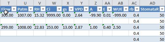
44 F1 F2 F3 F4 F5 F6 F7 F8 It is now safe to remove the USB flash drive from the CIRAS-3. Most people use Microsoft Excel to analyze the data. We are going to do the same here. Insert the USB flash drive into the USB port on your PC. Open Excel and go to File > Open and navigate to the USB flash drive and locate your data file in the Ciras-3\Data folder. Follow the instructions to open the file in Excel. Once retrieved your data should look similar to the following: RecType ExcelTime Comment CO2r CO2a CO2d H2Or H2Oa H2Od R R R R R PARi PARe Red Green Blue White Tamb Tcuv Tleaf Aleaf CIRAS-3 Operation Manual V support@ppsystems.com
45 Flow Patm RH Ci gs VPD A E WUE rb StomataR Tsensor Tcontrol Lcontrol PLC Status IR LA LED U IR LA LED U IR LA LED U IR LA LED U IR LA LED U There are 35 columns associated with leaf gas exchange data. Some variation may apply depending on the Excel software version that you are running. Also if you had entered comments to be included with your data they would appear in the Comment column. For this exercise we did not enter a comment so the column is blank. For more information on data leaf gas exchange data output refer to Application Gas Exchange and Analyzer Only on page 178. If you have our CFM-3 Chlorophyll Fluorescence Module and would like a quick tutorial on simultaneous measurement of leaf gas exchange and chlorophyll fluorescence please refer to the next section of the manual (see Measurement of Leaf Gas Exchange and Chlorophyll Fluorescence on page 46. Congratulations! You should now feel quite comfortable with the general operation of your CIRAS-3 system. If you have any questions whatsoever please feel free to get in contact with one of our technical staff for further assistance. Good luck with your research! CIRAS-3 Operation Manual V support@ppsystems.com
.")

 Part Number CRS301 CFM-3 Chlorophyll Fluorescence Module Part Number CRS306 Measurement of leaf gas exchange is identical to what is discussed in the previous section.")
46 Measurement of Leaf Gas Exchange and Chlorophyll Fluorescence In order to perform simultaneous measurement of leaf gas exchange and chlorophyll fluorescence you must have our CFM-3 Chlorophyll Fluorescence Module (Part No. CRS306). The CFM-3 has all the required light sources and detector for measurement of chlorophyll fluorescence based on the pulseamplitude modulated (PAM) measurement principle. The CFM-3 can also be used exactly the same as our LED light unit for automatic control of light intensity. For tutorial purposes this section will be based on the following system hardware to make it easier to follow along and comprehend: CIRAS-3 Main Console Part Number CRS300 PLC3 Universal Leaf Cuvette (with glass window in place) Part Number CRS301 CFM-3 Chlorophyll Fluorescence Module Part Number CRS306 Measurement of leaf gas exchange is identical to what is discussed in the previous section. However, in addition to making the appropriate selections under Settings (F2) for measurement of leaf gas exchange you also need to go to Set CFM-3 (F7) to configure the system for measurement of chlorophyll fluorescence. You must also make sure that the plain glass window is in place. If you purchased the CFM-3 with your CIRAS-3 system then the plain glass window is already fitted to your PLC3 Universal leaf Cuvette. In future if you change out the window for any reason refer to Replacement of PLC3 Glass Window (For Use with CFM-3) on page 227. For this tutorial we are going to set up the system to perform the following chlorophyll fluorescence measurements in addition to leaf gas exchange: Initial Fluorescence Measurement: F v /F m Repeated Fluorescence Measurement: ϕ PSII-SP Concluding Fluorescence Measurement: F o CIRAS-3 Operation Manual V support@ppsystems.com

 to configure the graph display as shown on the following page.")
47 Go to Settings (F2) and make the following selections: F1 F2 F3 F4 F5 F6 F7 F8 Next, go to Set CFM-3 (F7) and make the following selections: F1 F2 F3 F4 F5 F6 F7 F8 Once properly configured chlorophyll fluorescence measurements will be performed each time a leaf gas exchange measurement is performed after the initial F v /F m. After making your selections press Accept (F2). Next, press Set Graph (F6) to configure the graph display as shown on the following page. When in the Min field for CO2d press F3 to insert the negative (-) character (Graph2). CIRAS-3 Operation Manual V support@ppsystems.com
 to configure the Custom display as shown below: F1 F2 F3 F4 F5 F6 F7 F8 Press Accept (F2) > Accept (F2) when all selections are complete.")
48 F1 F2 F3 F4 F5 F6 F7 F8 Press Accept (F2) when all selections are complete. Next press Set Custom (F5) to configure the Custom display as shown below: F1 F2 F3 F4 F5 F6 F7 F8 Press Accept (F2) > Accept (F2) when all selections are complete. If you are not already at the Gas Exchange display press Toggle (F4) until you get to it. Close the leaf cuvette head without a leaf inserted. After approximately 2-3 minutes the system should stabilize and as discussed earlier should look similar to the display at the top of the following page. Note the environmental control settings and stable CO2d and H2Od readings with empty cuvette. CIRAS-3 Operation Manual V support@ppsystems.com
49 Recording Leaf Gas Exchange and Chlorophyll Fluorescence Data Now that we ve established that everything is working well and you are a bit more comfortable with the CIRAS-3 it is time to get set up to begin taking measurements on a real plant. Press Operations (F1) > Rec Options (F2) to create a data file where all readings will be saved to. Data can be recorded manually (by default), timed or as part of a response curve. For this exercise we are going to keep things simple and perform manual measurements of leaf gas exchange and chlorophyll fluorescence based on your selections under Settings (F2) and Set CFM-3 (F7) with the data saved to Internal Memory as shown at the top of the following page. Make sure that you have Manual Recording selected and Data File Folder is set to Internal Memory. CIRAS-3 Operation Manual V support@ppsystems.com
 and the data file is provided by default.")
50 F1 F2 F3 F4 F5 F6 F7 F8 Observe the following: Manual Recording is selected as indicated by the black highlighted radio button. The data file will be saved to Internal Memory (as indicated by the black highlighted radio button) and the data file is provided by default. Note that the default data file always starts with C3XXXX_YYYYMMDD_00 where: C3XXXX The serial number of your CIRAS-3 console YYYYMMDD Year/Month/Day 00 All data files start at 00 and count up from there (i.e. 01, 02, 03, etc.) unless changed by the user. Now would be a good time to place your leaf into the cuvette and close the head. To begin a recording session press Start (F2) > Back (F1) and then Record (F6) or R on the PLC3 Universal Leaf Cuvette. Please note that you must press Record (F6) or R in order to initiate a measurement sequence that involves measurement of chlorophyll fluorescence. Otherwise the system will not begin with the Initial Fluorescence Measurement which in this case is a F v /F m with a 30 minute initial dark adapt period as indicated in the status bar in the lower left hand corner of the display. The system will continue to count down until you reach the end of the dark adapt period after which it will perform the initial F v /F m measurement. CIRAS-3 Operation Manual V support@ppsystems.com
51 F1 F2 F3 F4 F5 F6 F7 F8 At the conclusion of the 30 minute dark adapt period the system will perform a F v /F m. Press Toggle View (F4) to see the values associated with F v /F m recorded. Also note that the status bar also confirms that the measurement was saved to the data file as shown below. F1 F2 F3 F4 F5 F6 F7 F8 All recorded measurements are confirmed in this area when stored to the data file. Press Toggle (F4) until you return to the Gas Exchange display. Next, wait for the plant to stabilize (approx. 60 seconds) after adjusting to the environmental conditions previously set under Settings (F2) and observe the following: CIRAS-3 Operation Manual V support@ppsystems.com
52 CO2d and H2Od should stabilize indicating that the leaf has reached equilibrium. Photosynthesis (A) & Stomatal Conductance (gs) should also stabilize. F1 F2 F3 F4 F5 F6 F7 F8 When readings are stable press Record (F6) on the CIRAS-3 console or the R key on the PLC3 to record leaf gas exchange data. Immediately after recording a leaf gas exchange measurement the system will next perform a Repeated Fluorescence Measurement ϕ PSII-SP and the data will be saved to the file as shown on the following page. This will continue each and every time you record a leaf gas exchange measurement per your Set CFM-3 (F7) settings. CIRAS-3 Operation Manual V support@ppsystems.com
53 F1 F2 F3 F4 F5 F6 F7 F8 At the conclusion of your leaf gas exchange measurements press End Record (F5) to allow the system to perform the Concluding Fluorescence Measurement F o per your Set CFM-3 (F7) settings to terminate the recording session. At completion you can press Toggle View (F4) to view the Chlorophyll Fluorescence display to view all final readings as shown below. F1 F2 F3 F4 F5 F6 F7 F8 Retrieving and transferring data from internal memory to a USB Flash Drive is simple and easy as described in the previous section highlighting measurement of leaf gas exchange (beginning on page 43). When the file is opened in Excel it should look similar to below. CIRAS-3 Operation Manual V support@ppsystems.com


54 CIRAS-3 Operation Manual V

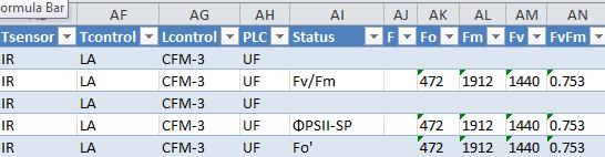
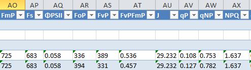
55 There are 55 columns of data associated with Gas Exchange and Chlorophyll Fluorescence measurements. Note that the Status column shows the row containing the fluorescence related data associated with Fv/Fm, ϕ PSII-SP and F o. For more information on data output that is associated with gas exchange and chlorophyll fluorescence measurements go to Application Gas Exchange and Chlorophyll Fluorescence on page 177. CIRAS-3 Operation Manual V support@ppsystems.com
 familiarize yourself with the basic CIRAS-3 set-up and operational functions and B) to ensure that the system")
56 Section 3. Quick Start We highly recommend that you take a few moments to run this simple test to A) familiarize yourself with the basic CIRAS-3 set-up and operational functions and B) to ensure that the system is performing perfectly before starting any measurement campaign. 1. Insert a new CO 2 cartridge, ensure all chemicals are fresh and connect the CIRAS-3 power supply to the CIRAS-3 main console (this will help to preserve the battery). 2. Connect the PLC3 Leaf Cuvette gas and signal connectors to the CIRAS-3 main console, close the cuvette (with no leaf present) and press the CIRAS-3 On/Off switch to power up the system and then Continue (F1) when the welcome screen appears. 3. Allow the system to warm up for approximately 30 minutes. Press Settings (F2) and make sure that that Application is set to Gas Exchange and Configuration is set to the appropriate leaf cuvette (change if necessary). Assuming that you are using the PLC3 Universal Leaf Cuvette (with 18x25mm window) and PLC3 Universal LED Light Unit set up as follows and press Accept (F2). For this simple test set the light source intensity to 500 µmol m -2 s -1 and to best simulate sunlight we recommend the following RGBW control settings: Red: 38% / Green: 37% / Blue: 25% / White: 0% CIRAS-3 Operation Manual V support@ppsystems.com
57 Allow the system a few minutes to stabilize at the values that were created under Settings (F2). Once stabilized, your display should look something similar to this. Observe the following: All measured data match up well with all environmental controls. The CO2r should be close to the set value of 390 (± 1.0 µmol m -1 ) and H2Or should be a reasonable value based on your local ambient %RH. The CO2d is close to 0 (± 0.5 µmol m -1 ) and H2Od is also close to 0 (± 0.05 mb). Tamb and Tleaf are reading similarly (± 0.2 o C) because you set the Temperature Control Type to Track Leaf to Ambient under Settings (F2). PARi is reading 500 µmol m -2 s -1 and stable (± 1-2 µmol m -2 s -1 ). If everything looks like this you should be good to go. Good luck! CIRAS-3 Operation Manual V support@ppsystems.com

58 Section 4. Summary of System Design Overview and Theory CIRAS-3 is designed to function as a self-contained open-system gas analyzer, manufactured and calibrated for high-precision detection of CO 2 and H 2 O gases. CIRAS stands for Combined Infra-Red Analysis System. Its open-path design allows for continuous, unattended air sampling, as the pumps introduce fresh sample gas to the essential components, the IRGAs. CIRAS-3, like previous generations of CIRAS, has four non-dispersive IRGAs (Infra-Red Gas Analyzers) CO 2 Reference, CO 2 Analysis, H 2 O Reference, H 2 O Analysis, a true differential analyzer. The IRGAs form the core of gas analysis systems that measure CO 2 and water vapor (i.e. Portable photosynthesis system, eddy covariance, soil CO 2 efflux, etc.). Non-Dispersive, Infra-Red (NDIR) refers to the transmission of broad-band infra-red wavelengths from the IRGAs source lamps. A single IRGA consists of four basic components: Infra-red source Sample cell of known path length and volume Optical interference filter Infra-red detector The theory itself is quite simple light from mid-infra-red wavelengths is produced by the source and pulsed through a gold plated cell. The interference filter narrows the bandwidth of the IR source received by the detector to the signature wavelength absorbed by the target gas molecule, e.g. CO 2. The CO 2 and H 2 O cells each employ a unique optical filter. As the sample gas fills the cell, it absorbs IR, and the reduction in IR source strength is measured instantaneously by the detector. The higher the target gas concentration, the lower the infra-red signal received at the detector, as defined by the Lambert-Beer Law of Attenuation. CIRAS-3 Operation Manual V support@ppsystems.com
59 Both H 2 O and CO 2 molecules have diverse absorption spectra, so we use two prominent absorption peaks, seen below at 2.60 and 4.26 µm, respectively. CIRAS-3 s electronics could be considered the fifth component, which processes raw analog-to-digital (A/D) information from the IRGAs detectors, accurately translating this information into gas concentrations. The gas sample is of course a mixture of gas molecules, and this can present problems in terms of accurate detection of concentrations of a specific gas, such carbon dioxide. This effect, foreign gas broadening (FGB), must be corrected to ensure accurate measurement of gas concentrations. With FGB, the CO 2 gas in the IRGA cell is somewhat diluted by the increased air volume induced by water vapor. This effect is about 0.1 µmol mol -1 CO 2 mb -1 H 2 O. The presence of water vapor also causes an increase in infra-red absorption, which is detected as an apparent increase in [CO 2 ]. This is of a similar magnitude, but opposite to the dilution effect, and CIRAS-3 automatically corrects these FGB effects. CIRAS-3 s IRGAs are quite stable owing to their construction, calibration and thermal environment, but various circumstances can cause apparent changes over time. Some changes may require recalibration, although one of the strengths of CIRAS-3 is that recalibration is not a routine (annual) maintenance task. The factory calibration ranges of µmol mol -1 CO 2 and 0-75 mb water vapor are ideally suited for most typical gas exchange applications. CIRAS-3 Operation Manual V support@ppsystems.com
60 Factory linearization of the IRGA cells is standard, but slight differences between IRGAs are inherent due to the uniqueness of optical filters and reflection characteristics of the cells - this is common to all differential analyzers. Still, the Reference and Analysis cells should be made to match a standard such as Zero air, and CIRAS-3 s Auto Zero function corrects for nearly all changes that result in calibration drifts. Auto Zero minimizes effects on span (gas sensitivity), of sample cell contamination, lamp ageing, changes in detector sensitivity, amplifier gains and reference voltages. Measurements are ratioed to the Zero reading before IR absorbance is determined. From the relationship between absorbance and concentration determined in the factory for each instrument, and the current calibration factor, the sample concentration is determined. We overcome short-term drifts by use of a second mode, called Differential Balancing or Diff Bal. Using Diff Bal temporarily diverts only Reference air through all cells (Reference and Analysis). If existing offsets are detected between the Reference and Analysis cells while measuring the same Reference gas sample, appropriate correction factors are calculated to equalize the readings of each cell pair. This way, you can have confidence that a reported differential between the Reference and Analysis cell pair is real and not artificial. An overview of the gas circuit design of CIRAS-3 configured for leaf-level photosynthesis is shown in the schematic on the following page. Sample air, denoted as AIR IN, entering the console and is first pumped and its flow rate metered, then directly conditioned by passing through CO 2 and water vapor absorbent chemicals. At this point CO 2 can be added to the gas stream in a precise mixture from the CO 2 source cartridge, while existing water vapor can be removed from the gas stream or allowed to remain at its current partial pressure, measured in mb. One portion of the mixed air (AIR OUT) is then passed along downstream to be measured at the Reference IRGAs. The other portion is sent to the leaf chamber before returning to the Analysis IRGAs. REF (Reference) and AN (Analysis) air are drawn into the IRGAs at precisely controlled flow rates by respective REF and AN pumps. The IRGAs are contained in a rugged, sealed case and taken together form the thermally-stable optical bench. CIRAS-3 Operation Manual V support@ppsystems.com
61 As you can see, the delivery and measurement of the gas depends on a system of three pumps working together. For the main air supply pump we use a diaphragm type pump, and for the Reference and Analysis cells we use rotary vane pumps. All pumps are under user control, allowing you to determine and set an optimal flow rate of air to the cuvette and leaf (air supply pump) as well as the sampling rate by the IRGAs (reference and analysis pumps). We also ensured that the different path lengths of the REF and AN gases from source to IRGA are accounted for, and with only a very small delay in response time, the displayed console REF and AN readings are nearly instantaneous. In addition, Zero valves are periodically activated for Zero or Diff Bal functions, diverting the gas streams from their normal paths. CIRAS-3 Operation Manual V support@ppsystems.com
62 Section 5. System Hardware CIRAS-3 Main Console The CIRAS-3 console houses the IRGAs, gas circuit including absorber columns with chemicals, gas and electrical connections, on-board computer, color display and keypad. The console is the base instrument for several different possible applications including leaf gas exchange, chlorophyll fluorescence, canopy assimilation, soil respiration, analyzer platform for custom-built chambers (both closed- and open-system) and direct measurement of gaseous CO 2 and H 2 O. A C B A. Large, full color, transflective LCD optimized for field use.. B. Tactile feel keypad and function keys for system navigation and user inputs. C. Battery compartment and main access to internal components. On the front side of the console you find the user interface with its 30 display and keypad group used to navigate the CIRAS-3 console menus. Access to the Li-ion battery pack(s) and internal mechanical and electrical components is achieved by loosening the two captive screws (turn counter-clockwise to release) and gently lowering the door. CIRAS-3 Operation Manual V support@ppsystems.com


63 System Power Power Supply Adapter An AC power supply adapter (120/240 VAC / 50/60 Hz) is included with the CIRAS-3. If mains power is available the system can be operated continuously using the power supply adapter. This same adapter is also used to charge the internal battery packs. You must use the power supply adapter supplied by PP Systems as other types may cause damage to the instrument. Battery Pack For field use the system is powered by internal, rechargeable battery packs. Up until June 2017 the CIRAS-3 was powered by a single, internal rechargeable 7.2V Li-ion battery pack (Aved) providing system operation up to 8 hours. Starting in July 2017 we began supplying instruments with two 7.2V (8.7 Ah, 63 Wh) Li-ion battery packs (Inspired Energy) improving system operation for up to 12 hours (actual operation time will vary depending on environmental control settings). If users want to update to our latest battery technology they should get in direct contact with PP Systems. Battery Pack (Aved) Part Number Battery Pack (Inspired Energy) Part Number ALWAYS MAKE SURE THE BATTERY PACKS ARE FULLY CHARGED THE NIGHT BEFORE USE. CIRAS-3 Operation Manual V support@ppsystems.com

64 Please note that batteries are shipped only partially charged due to shipping regulations. We highly recommend that you charge them to full capacity upon receipt to avoid any potential damage or loss of battery life. TIP To reduce the weight of the CIRAS-3 console approximately 0.2 kg you can remove one of the battery packs providing up to 6 hours of continuous use (depending on settings and controls) in the field. We recommend 2 battery packs for normal use but if one battery pack is used it must be placed in the lower battery compartment which is the one that is flush with the inside battery compartment door as shown above. There are two major factors that influence battery capacity: Environmental control CFM-3 Chlorophyll Fluorescence Module For field use, it is extremely important to make sure that the internal battery(s) are fully charged. We also offer a nice, lightweight external battery pack that can clip easily to your belt for extended operation time in the field. See External Battery Pack (For extended operation in the field) on page 207 for more details. CIRAS-3 Operation Manual V support@ppsystems.com


65 Battery Pack Installation When systems are first supplied the batteries are packed inside the CIRAS-3 console in Ship Mode. Upon receipt of your new instrument you must remove the packs from each compartment to put them into Run Mode as shown below. Ship Mode Run Mode Instructions: 1. Open battery compartment door on the front of the CIRAS-3 console (2 smalls screws) to access the internal battery packs and gently drop down the door. 2. Remove battery retaining bracket which is currently in the Ship position. 3. Remove both battery packs from each compartment by pulling on the black TAB. 4. Flip each battery pack over and re-insert into each compartment to snap into place with the groove facing downwards towards the battery compartment door. The battery gauge should be facing outwards and the battery removal black TAB should be on the top of the battery pack. 5. Secure in place with the retaining bracket in the Run position. 6. Close battery compartment. CIRAS-3 Operation Manual V
 has a charge indicator gauge on the side to show the level of charge. When all 5 bars are dark it indicates that the pack is fully charged (see below).")
66 Charging Batteries inside the CIRAS-3 Console An AC power supply adapter (120/240 VAC / 50/60 Hz) is supplied with the CIRAS-3 for charging the internal battery packs. Each battery pack (Inspired Energy type) has a charge indicator gauge on the side to show the level of charge. When all 5 bars are dark it indicates that the pack is fully charged (see below). Please note that the CIRAS-3 also reports the state of the battery packs in the lower right hand corner of the display when the instrument is powered on. See Battery Pack (Li-ion Battery) on page 205 for instructions on battery removal, storage and disposal. CIRAS-3 Operation Manual V support@ppsystems.com

67 CIRAS-3 Rear Console The CIRAS-3 rear console contains all of the essential components including power, gas and electrical connections, USB ports, charger socket, desiccants (scrubbers) and CO 2 cartridge holder. Battery charging socket and LED USB flash drive ports Power Mini USB PLC connections CO 2 cartridge holder Gas ports and link pipe Auxiliary connector for use with SRC-1/2 and CPY-4/5 Zero columns CO 2 /H 2 O control columns and H 2 O equilibrator USB Flash Drive Ports There are two USB flash drive ports labeled USB1 and USB2. These are used for downloading/uploading stored data files and for transfer of settings and response script files. CIRAS-3 Operation Manual V support@ppsystems.com

68 Battery Charging Socket (EXT PWR) and LED The power supply adapter connects to the EXT PWR socket to charge the internal batteries and to power the system continuously. The LED should be steady green indicating secure connection and that the internal batteries are getting charged. Power The ON/OFF power button is a push-and-release type switch that will illuminate blue when the instrument is turned on. Mini-USB (PC) The Mini-PCB socket (PC) is a communication port for connection to a laptop or desktop computer and is commonly used with the PC Utility Software for CIRAS-3 remote operation and display. A suitable USB cable is included with the CIRAS-3. See PC Utility Software on page 195. PLC Connections The white plastic gas connector on the PLC3 connects to the port labeled PLC GAS and the 4 pin black electrical plug connects to the socket labeled PLC SIGNAL. Both the reference and analysis gas lines are built into this single pneumatic connector which is secured by a locking connector. Push firmly in until you hear a click and to release press down on the silver TAB at the top of the connector and pull the connector out. DO NOT USE EXCESSIVE FORCE WHEN CONNECTING OR DISCONNECTING THE PNEUMATIC CONNECTOR AS IT MAY RESULT IN DAMAGE. The black electrical signal connector has a small black arrow used to align the connector with the SIGNAL socket. Align the arrow to the top center position and push in until it locks. Pull gently on the connector s sliding lock barrel to remove. CO 2 Cartridge Holder The CO 2 cartridge fits inside the cartridge holder which threads into the regulator body in the opening labeled CO 2 on the CIRAS-3 console. CO 2 Cartridge Holder CO 2 Cartridge CO 2 Regulator CIRAS-3 Operation Manual V support@ppsystems.com

69 CO 2 Cartridges We supply and recommend the CO 2 cartridges that are manufactured by a company called ISI. The cartridges are 8g and are normally supplied in boxes of 10 as shown here. A fresh CO 2 cartridge has a very high pressure when it is first introduced into the CIRAS-3 console. We do not recommend changing the cartridge for at least 24 hours from the time it is inserted due to this high pressure. Use precaution when changing the CO 2 cartridge. If you attempt to change a highly pressurized CO 2 cartridge you will observe a very rapid escape (and loud pop) of gas from the cartridge when you slowly unscrew the cartridge holder from the CIRAS-3. You will also observe that the cartridge will be quite cold. Manufacturer Contact Information ISI Kürschnergasse 4 A-1217 Vienna, Austria Tel: Fax: info@isi.at URL: NOT ALL CO 2 CARTRIDGES ARE THE SAME AND SOME MAY EVEN CAUSE DAMAGE IF USED WITH THE CIRAS-3. They come in all different sizes, shapes and contents (some even have oil) and are commonly used for things like pellet guns, soda siphons, etc. If you have any questions whatsoever regarding the CO 2 cartridges you are urged to get in contact directly with PP Systems. Gas Ports and Link Pipe AIR IN is the entry port for ambient air or introduced air from an external gas cylinder (i.e. experimental air containing 2% oxygen). A short link pipe connects AIR OUT with REF IN. This is actually the reference air supply air for both the reference IRGAs and the leaf cuvette. For leaf gas exchange measurements using any of our PLC3 leaf cuvettes and for insect respiration measurements, this link pipe must be connected between the REF IN and AIR OUT. The AN OUT and REF OUT ports allow sampled air to exhaust to atmosphere. Auxiliary Connector The 4 pin AUX socket is reserved for use with the SRC-1/SRC-2 Soil Respiration Chambers and the CPY-4/CPY-5 Canopy Assimilation Chambers. CIRAS-3 Operation Manual V support@ppsystems.com
70 Please note that the SRC-1 Soil Respiration Chamber and CPY-4 Canopy Assimilation Chamber also require an additional piece of hardware called the Auxiliary Probe Adapter (APA) to work with CIRAS-3. Contact PP Systems for more details if you would like to use the SRC-1 and CPY-4 with CIRAS-3. Zero Column The Zero column contains 3 clearly marked desiccants labeled CO2 Absorber (soda lime), H2O Absorber (Drierite) and MS (Molecular Sieve) which are used for the analyzer Zero ensuring long term stability and accuracy of the CO 2 and H 2 O gas analyzers. Therefore it is critical that these desiccants are maintained properly to ensure system accuracy. See Desiccants and Absorber Columns on page 211 for more information related to this column and management of desiccants. To play it safe and for best results we recommend that you change out the Molecular Sieve desiccant on a daily basis prior to performing measurements to ensure accurate Auto Zero and long term accuracy and stability of the CO 2 and H 2 O gas analyzers. CO 2 /H 2 O Control Columns and H 2 O Equilibrator The CO 2 /H 2 O control columns contain 2 clearly marked desiccants labeled CO2 Absorber (soda lime) and H2O Absorber (Drierite) which are used to control CO 2 and H 2 O. See Desiccants and Absorber Columns on page 211 for more information related to this column and management of desiccants. TIP To play it safe and for best results we recommend that you change out the Molecular Sieve desiccant on a daily basis prior to performing measurements to ensure accurate Auto Zero and long term accuracy and stability of the CO 2 and H 2 O gas analyzers. See Desiccants and Absorber Columns on page 211. We also strongly recommend performing a leak test every time you change the desiccants. To do so insert a fresh CO 2 cartridge, connect the PLC3 Leaf Cuvette electronically and pneumatically and close the cuvette head. Go to Controls (F3) and set the CO 2 reference to 0. The CO2r and CO2a values should drop close to 0 (± 2 ppm) after a few minutes with a 0 CO2d (± 0.5 ppm). If any problems persist perform additional leak tests to try and isolate the source of the leak (See Checking For Leaks Associated With the PLC3 on page 221. CIRAS-3 Operation Manual V support@ppsystems.com

.")
71 PLC3 Series Leaf Cuvettes There are 3 standard leaf cuvettes commonly used with the CIRAS-3 for measurement of leaf gas exchange: PLC3 Universal Leaf Cuvette For measurement on flat, broad leaves. It is supplied as standard with 3 windows measuring 25 x 7 mm, 25 x 18 mm and 18 mm diameter. PLC3 Narrow Leaf Cuvette For measurement on grasses, long needles and narrow leaves. PLC3 Conifer Leaf Cuvette For measurement on conifers and short needle vegetation. All 3 PLC3s connect to the PLC Gas and Signal connectors on the CIRAS-3 console. Prior to use, make sure that the gas and signal connections are made and that the appropriate PLC3 is selected under Settings (F2). See Settings Gas Exchange on page 143 for measurement of gas exchange and Application Gas Exchange and Chlorophyll Fluorescence on page 131 for measurements of gas exchange and chlorophyll fluorescence. When selected, the default values for that leaf cuvette will be used. This is very important as there are some differences between the PLC3s. All 3 leaf cuvettes have a similar handle, electronics, sensors, LCD, record (R) and switch (S) keys on the open/close lever, ambient temperature sensor, temperature control range and external PAR sensor. Measurements can be recorded from all PLCs by pressing the R key and parameters can be toggled on the LCD by pressing the S key. CIRAS-3 Operation Manual V support@ppsystems.com
72 PLC3 Temperature Control All PLC3s include temperature control as standard. Each PLC includes a built-in Peltier heating/cooling module which allows a wide range of temperature control. Optimal control depends on the ambient air temperature due to power requirements to heat or cool the cuvette or leaf to temperatures that are much different than ambient. With full power available you can usually control cuvette temperature (Tcuv) from approximately 10 C below ambient to 15 C above ambient, but within the absolute temperature range of 0 to 45 C. Note that slight differences are expected between sensor-based and calculation-based methods. Automatic control of leaf temperature is heavily influenced by the following 3 variables: 1. Leaf transpiration in the cuvette 2. Light (incident radiation) 3. Size and construction of the PLC window At lower light intensities, leaf temperature control is wider and at high light intensities it is much tighter. We recommend that when using Leaf Temperature as the Temperature Control Type under Settings (F2) that you do so maintaining leaf temperature (Tleaf) at or near ambient levels especially at high light intensities and transpiration rates. Although all PLC3s include temperature control as standard, there are some key differences between each type as described in the following sections. Temperature Measurement PLC3 Universal Includes an IR sensor for accurate, non-contact measurement of leaf temperature and energy balance for calculation of leaf temperature. We recommend the IR sensor as long as the entire cuvette window is covered with leaf material. If the cuvette window is not covered 100% with leaf material, you must select energy balance. The Energy Balance calculation estimates leaf temperature by equating energy flux into the leaf with energy flux out of the leaf. The model includes incident solar radiation, leaf re-radiation, convective heat transfer, and transpiration. PLC3 Narrow and Conifer Includes a leaf thermistor for direct measurement of leaf temperature and energy balance for calculation of leaf temperature. We recommend the energy balance method. Temperature Control Type PLC3 Universal Five control options are available: Leaf temperature Track Leaf to Ambient Cuvette Temperature Track Cuvette to Ambient Disable Temperature Control CIRAS-3 Operation Manual V support@ppsystems.com

73 PLC3 Narrow and Conifer Three control options are available: TIP Cuvette Temperature Track Cuvette to Ambient Disable Temperature Control The PLC3 ambient temperature sensor will represent the approximate ambient temperature for reference purposes only. Tamb may vary 1-3 o C from actual ambient depending on local conditions and orientation of the cuvette. LCD on Leaf Cuvette All PLCs include an LCD for display of parameters. Press the S button located on the cuvette open/close lever to toggle between displays to view additional parameters. Display 1 A (Assimilation) Ci (Intercellular CO 2 ) E (Evaporation) ) gs (Stomatal Conductance) Display 2 CO2r (CO 2 Reference) H2Or (H 2 O Reference) Display 3 CO2d (CO 2 Differential) H2Od (H 2 O Differential) Press R to record a measurement if in record mode. CIRAS-3 Operation Manual V support@ppsystems.com
 for measurement of ambient PAR. This reading will be most reliable with the cuvette held on a horizontal plane relative to the ground.")
 by the window.")
74 PAR Measurement The PLC3 leaf cuvettes also feature two ways of measuring light in the nm wavelengths commonly referred to as Photosynthetically Active Radiation or PAR. All PLC3s include a cosinecorrected external PAR sensor (PARe) for measurement of ambient PAR. This reading will be most reliable with the cuvette held on a horizontal plane relative to the ground. PLC3 Universal - Includes two mini-silicon photodiode sensors beneath the cuvette window (PARi). The silicon photodiode sensors are close to the leaf plane and used to average the irradiance beneath the cuvette window. Irradiance is somewhat attenuated (approx. 10% attenuation) by the window. This affects the amount of light reaching the leaf if the light source is ambient sunlight, but not if our LED light unit is the source. This is because the internal PAR sensors are on an electronic feedback loop with the light unit, so the desired light intensity entered by the user is always achieved. PLC3 Conifer and Narrow Includes a single, cosine corrected PAR sensor beneath the cuvette window (PARi). It is used to give an indication of the PAR inside the leaf cuvette and as an electronic feedback loop to control light intensity when our light unit is used. PLC3 Universal Leaf Cuvette PARe PLC3 Conifer and Narrow Leaf Cuvette PARe PARi PARi TIP The PARi sensor will normally read about 10% lower than the PARe sensor due to attenuation of the cuvette window. CIRAS-3 Operation Manual V support@ppsystems.com

 An optional LED Light Unit is available for all PLC3s.")
75 Connection of PLC3 Leaf Cuvettes to the CIRAS-3 All PLC3 leaf cuvettes connect electrically to the 4 pin PLC SIGNAL socket on the CIRAS-3 console via the black 4 pin plug. This connection has a notch at the top so make sure you line up the arrow on the top of the black plug to the top middle section of the SIGNAL socket on the console. A white pneumatic gas connector mates to the PLC Gas port on the CIRAS-3. It will snap into place. A link pipe between REF IN and AIR OUT must be in place as shown here when performing gas exchange measurements. Light Control (Optional) An optional LED Light Unit is available for all PLC3s. PLC3 Universal LED Light Unit (RGBW) This LED light unit features 48 LEDs, 12 each of RGBW (redgreen-blue-white) color. You are able to set any single color from 0-100% using the light source, or you can combine colors in any proportion to recreate the spectral distribution of a specific natural or artificial light source. With full power available to the cuvette the normal intensity output range will be µmol m -2 s -1. Caution: do not look directly at illuminated LEDs, even with the light unit set to lower intensity control levels. Please note. Maximum light intensity and range of temperature control is dependent on RGBW settings. CIRAS-3 Operation Manual V support@ppsystems.com


76 Connection of Light Units and CFM-3 Chlorophyll Fluorescence Module to CIRAS-3 The PLC3 Universal LED light unit and CFM-3 Chlorophyll Fluorescence Module are designed to connect to the PLC3 Universal Leaf Cuvette exactly the same quickly and easily. Step 1 First, mount the light unit by aligning it to the front of the cuvette upper jaw as shown below. Step 2 Slide the light unit back towards the heat sink and fan on the leaf cuvette locking it in place using the two ball-head screws shown below. Step 3 Connect electrically by gently pressing the connector in. Pay special attention to align the red dots on the plug and connector. PLC3 Narrow and Conifer LED Light Unit This LED light unit for the PLC3 Narrow and Conifer leaf cuvettes feature 96 LEDs, 24 each of RGBW (red-green-blue-white) color. You are able to set any single color from 0-100% of the light source, or you can combine colors in any proportion to recreate the spectral distribution of a specific natural or artificial light source. With full power available to the cuvette the normal intensity output range will be µmol m -2 s -1 (ranges are dependent on selection of red-green-blue-white LEDs). Caution: do not look directly at illuminated LEDs, even with the light unit set to lower intensity control levels. CIRAS-3 Operation Manual V support@ppsystems.com


77 The PLC3 Narrow and Conifer LED light unit is designed to mate quickly and easily with the PLC3 Conifer or Narrow leaf cuvette. Step 1 Secure light unit to notches on cuvette head. Step 2 Pull light unit over cuvette and secure locking screw. Step 3 Connect electrically by gently pressing the connector in. Pay special attention to align the red dots on the plug and connector. Please note. Maximum light intensity and range of temperature control is dependent on RGBW settings. Also, due to the distance between the LEDs in the light unit and the PLC3 Narrow and Conifer internal PAR sensor, maximum light intensity may be lower than 2000 µmol m -2 s -1 depending on mixture of red, green, blue and white LEDs. CFM-3 Chlorophyll Fluorescence Module The CFM-3 Chlorophyll Fluorescence Module looks very similar to the PLC3 Universal LED Light Unit. The major difference being the inclusion of all fluorescence associated light sources and detection capability that is built directly into the light unit. Attachment and connection to the PLC3 Universal Leaf Cuvette is identical to that described above with the PLC3 Universal LED Light Unit. See Connection of Light Units and CFM-3 Chlorophyll Fluorescence Module to CIRAS-3 on page TIP The CFM-3 can also be used as an actinic light source for gas exchange measurements if required. CIRAS-3 Operation Manual V support@ppsystems.com

 Range: 0-50 o C Accuracy: ± 0.")
78 SRC-2 Soil Respiration Chamber Our SRC-2 Soil Respiration Chamber is available for use with the CIRAS-3 for measurement of soil CO 2 efflux (Closed System). The SRC-2 Soil Respiration Chamber is constructed out of rugged PVC with a convenient handle for placement on the soil surface. An aluminum ring provides a good seal on the soil surface or on collars. Dimensions: 150 mm (Height) x 100 mm (Diameter) Volume: 1171 ml Area: 78 cm 2 Cable Length: 1.5 meters It includes a temperature sensor for measurement of air temperature near the soil surface. Optional soil collars are available from PP Systems. Temperature Sensor (Precision Thermistor) Range: 0-50 o C Accuracy: ± 0.3 o C at 25 o C CPY-5 Canopy Assimilation Chamber Our CPY-5 Canopy Assimilation Chamber is available for use with the CIRAS-3 for measurement of net canopy CO 2 flux (Closed System). It connects electrically direct to the 4 pin AUX socket on the CIRAS-3 console via the black 4 pin plug. The CPY-5 Canopy Assimilation Chamber is constructed out of rugged polycarbonate. An aluminum ring provides a good seal on the soil surface or on collars. It also includes sensors for air temperature and PAR (Photosynthetically Active Radiation) inside the chamber near the soil surface. Optional collars are available from PP Systems. Dimensions: 145 mm (Height) x 146 mm (Diameter) Area: 167 cm 2 Cable Length: 1.5 meters Temperature Sensor (Precision Thermistor) Range: 0-50 o C Accuracy: ± 0.3 o C at 25 o C CIRAS-3 Operation Manual V support@ppsystems.com


79 PAR Sensor Fully cosine corrected Range: µmol m -2 s- 1 Accuracy: ± 10 µmol m -2 s- 1 We recommend recalibration of the PAR sensor every 2 years. The temperature sensor should not require recalibration. Connection of Closed System Chambers to the CIRAS-3 Both the SRC-2 Soil Respiration Chamber and CPY-5 Canopy Assimilation Chamber connect electrically to the 4 pin AUX socket on the CIRAS-3 console via the black 4 pin plug. This connection has a notch at the top so make sure you line up the arrow on the top of the black plug to the top middle section of the AUX socket on the console. The link pipe between REF IN and AIR OUT must be removed to allow connection to the REF IN port for both the SRC-2 and CPY-5. Connect the Gas In line to the REF IN and Gas Out to the REF OUT gas ports on the CIRAS-3 console. The CPY-5 Canopy Assimilation Chamber is also supplied with a water vapor equilibrator which we recommend for use in high humidity environments. The water vapor equilibrator should be plumbed on the REF IN line as shown here. When in use, the equilbrator should be positioned in a way to allow air to flow through the venting to allow the moisture to equilibrate with the ambient. Do not let it sit flat on the ground. CIRAS-3 Operation Manual V support@ppsystems.com
 or H 2 O (Drierite) with some of our CO 2 gas analyzer products.")

80 Insect Respiration Chamber A chamber is available for use with the CIRAS-3 for measurement of insect respiration. The chamber is basically one of our standard absorber columns normally used with desiccants for scrubbing CO 2 (soda lime) or H 2 O (Drierite) with some of our CO 2 gas analyzer products. It works perfectly for measurement of insect respiration by simply placing an insect(s) inside the chamber. The black end caps can be removed by simply pulling on it from either end making it very easy to introduce insects into the chamber. Chamber Volume: 33 cm 3 (Not including gas tubing) Chamber Dimensions: 15.1 cm (L) x 25 cm (Diameter) Chamber Weight: 65 g Connection of the Insect Respiration Chamber to the CIRAS-3 There are no electrical connections required. Connect the white pneumatic connector to the PLC Gas port on the CIRAS-3. It will snap into place. Connect the short gas tubing labeled A to one end of the chamber and the longer length tubing on the Y connector to the other end of the chamber. The small length of tubing on the Y connector is used as a vent to atmosphere. A link pipe between REF IN and AIR OUT must be in place as shown here when performing gas exchange measurements. A link pipe between REF IN and AIR OUT must be in place as shown here when performing insect respiration measurements CIRAS-3 Operation Manual V support@ppsystems.com

81 Section 6. Navigation and General Overview System Navigation The CIRAS-3 console software is very user-friendly and incredibly intuitive with context-sensitive help available throughout the software. All CIRAS-3 functions are accessed and implemented by the same easy-to-understand software structure Settings, Controls, Recording, Data Transfer, Diagnostics, Calibrations and other useful functions. The CIRAS-3 Console software is the system s command interface, based on function keys linked to sub level menus. Once you become familiar with how the menus are organized, navigation through menus becomes simple decide what you want to do and with a few key presses make your selections. Navigation Function Keys (F1-F8) TAB DEL OK ESC Arrow Keys There are 8 function keys located on the main keyboard labeled F1-F8. Function keys form the top level for menu selections. Function keys are context-sensitive, so as you go deeper into a menu their assigned functions may change. The TAB key is typically used to navigate from field to field within a dialog. Once in a field you can use the keypad to enter numeric values or delete characters. Also, you can use the Expand List (F4) key to expand the list of available selections within a field if applicable. Allows you to delete characters in a field or to simply backspace in the field. Confirms your selection from a dropdown list or from within a window that may appear from time to time. Closes down the dropdown list within fields. Used to move up and down one item at a time within a list, or to move horizontally to make selections from buttons that may be displayed CIRAS-3 Operation Manual V support@ppsystems.com

82 Select Accept (F2) when you are ready to accept any changes to dialogs or Cancel (F1) to reject changes. After accepting changes a message will be displayed in the lower left hand corner of the display confirming the changes. System Help System help is available from any screen and is context-sensitive to the functions being displayed or performed. Press Help (F8) whenever you have a question or concern about the information that is being displayed at any given point in time. For example, if you have the Settings dialog displayed press Help (F8) for help related to this dialog. Within the Help screen press Page Up (F3) or Page Down (F4) to read more content if applicable. Press Display Log (F5) to see a running log of your session that saves calibration functions, warnings and error messages with time stamps. Press Display Help (F5) to return to the Help dialog. F1 F2 F3 F4 F5 F6 F7 F8 CIRAS-3 Operation Manual V support@ppsystems.com
83 Main Data Viewing Displays All five CIRAS-3 Applications include at least one numeric and one graph display to view measured and calculated data. For several Applications including Chlorophyll Fluorescence, Gas Exchange and Gas Exchange and Chlorophyll Fluorescence we offer one additional custom display which allows users to determine only the parameters that they want displayed. All measured and calculated data displayed on the screens are based on both the Application and Configuration selections under Settings (F2). Users can toggle from display to display by pressing Toggle View (F4). Numeric Display (Gas Exchange) F1 F2 F3 F4 F5 F6 F7 F8 You will see that parameter fields have either a light blue header or dark blue header. Generally speaking, any fields with a light blue header are measured parameters and fields with dark blue headers are calculated parameters. CIRAS-3 Operation Manual V support@ppsystems.com

84 Numeric Display (Chlorophyll Fluorescence) F1 F2 F3 F4 F5 F6 F7 F8 Graph Display F1 F2 F3 F4 F5 F6 F7 F8 CIRAS-3 Operation Manual V
85 Custom Display F1 F2 F3 F4 F5 F6 F7 F8 CIRAS-3 Operation Manual V
 From any numeric, graph or custom display press Operations (F1) to access numerous system functions including: Recording Options (Rec Options - F2) Set Clock (F3) View saved data")
86 Section 7. Operations (F1) From any numeric, graph or custom display press Operations (F1) to access numerous system functions including: Recording Options (Rec Options - F2) Set Clock (F3) View saved data (View Saved - F4) Calibration (F5) Diagnostics (F6) Firmware Upgrade (FW Upgrade - F7) Help (F8) Rec Options (F2) Press Operations (F1) > Rec Options (F2) to set up a recording session. There are 3 options available as follows: Manual Recording Normally used for individual leaf level gas exchange measurements. Timed Recording For performing measurements at user-defined time intervals. Response Curves For automated, pre-programmed scripts for A/C i curves, light response, etc. F1 F2 F3 F4 F5 F6 F7 F8 CIRAS-3 Operation Manual V support@ppsystems.com
87 Manual Recording Select the desired recording option at the top of the dialog by using the right and left arrow keys. Highlight Manual Recording and press TAB to select it and move to Data File Folder. For most leaf gas exchange measurements in the field this method of recording is most common. Data Storage and Filenames Data File Folder Start Recording Data File Data can be saved to Internal Memory or directly to a USB Flash Drive. Highlight the desired storage location and press TAB to select it. A default data file name will appear here. Note that the default data file always starts with C3XXXX_YYYYMMDD_00 where: C3XXXX The serial number of your CIRAS-3 console YYYYMMDD Year/Month/Day 00 All data files start at 00 and count up from there (i.e. 01, 02, 03, etc.) unless changed by the user. FOLDER: \Flash Disk\Ciras3\Data\ Folder: \USB Storage\Ciras3\Data\ You can the change the filename if required using the DEL key to backspace and delete characters and using the keyboard enter your own numeric filename. You cannot overwrite an existing data file. Later, you can export the file and rename it using alpha characters if required. Indicates the Internal Memory location where data files are stored and the box beneath it lists all currently stored data files. Indicates the USB Flash Drive location where data files are stored and the box beneath it lists all currently stored data files on the USB Flash Drive. If a USB Flash Drive is not in place in one of the two available USB ports on the CIRAS-3 rear panel the message USB Flash Drive Not Detected will appear in this box. Press Start (F2) to begin recording data you are automatically returned to the Operations dialog. The status bar indicates that you are now in Record mode. Press Back (F1) to return to the Numeric Display (or the last display you were in prior to initiating a recording session). Measurements can be initiated and recorded by pressing Record (F6) on the CIRAS-3 console. If using one of our PLC3 Leaf Cuvettes you can also press the R key on the cuvette s open/close lever to record data. A message Recording will appear on the small PLC display indicating the data was recorded. CIRAS-3 Operation Manual V support@ppsystems.com
88 When a measurement is recorded a message similar to the following will be displayed in the status bar in the lower left hand corner of the display: Record 1 Saved to File: C30235_ _00.xml If viewing the graph display a red triangle will also appear in the graph each time a measurement is recorded. To terminate a measurement session press End Record (F5). TIP Under Settings (F2), if the Application selected is Chlorophyll Fluorescence or Gas Exchange and Chlorophyll Fluorescence recording begins by pressing Start (F2) > Back (F1) > Record (F6) or R on the PLC3 Universal Leaf Cuvette to initiate a measurement sequence. If you forget to press Record (F6) or R the system will not begin a measurement sequence. Also, Manual Recording is the only available recording option for the Application Chlorophyll Fluorescence. Timed Recording Using the right and left arrow keys highlight Timed Recording and press TAB to select it and move to Time Intervals. Press Expand List (F4) to drop down the available selections in the list. Data can be recorded automatically at intervals from 2 seconds to 30 minutes. Select your recording interval and press TAB to select it and move to Data File Folder. F1 F2 F3 F4 F5 F6 F7 F8 CIRAS-3 Operation Manual V support@ppsystems.com
89 Recording, data storage and filenames are treated exactly the same as described in Data Storage and Filenames on page 87. When measurements are under way the status bar in the lower left hand corner of the display will show the countdown to the next record: Next record in Timed Recording will continue indefinitely at the selected recording interval unless you press End Record (F5) to terminate a recording session or if you pause a recording session. To pause a recording session press Operations (F1) > Rec Options (F2) > Pause (F3). To resume a recording session press Resume (F3) to continue Timed Recording. Response Curves Using the right and left arrow keys highlight Response Curves and press TAB to select it and move to Response Curve Scripts. Press Expand List (F4) to view and select available scripts stored on the CIRAS-3 console using the up and down arrow keys. After selecting the required script press the TAB key to advance to the Data File Folder. The CIRAS-3 is supplied with several simple default scripts stored on the console which can be executed, modified or overwritten. F1 F2 F3 F4 F5 F6 F7 F8 Recording, data storage and filenames are treated exactly the same as described in Data Storage and Filenames on page 87. CIRAS-3 Operation Manual V support@ppsystems.com

90 TIP When performing automatic response curves involving chlorophyll fluorescence measurements, all settings (Settings (F2) > CFM-3 Settings (F7)) must be set up and saved prior to starting a measurement sequence in order to take effect. There are multiple options available to create and edit your own response curve protocols to automatically run response curves. This can be done on the CIRAS-3 console, on a computer using the PC Utility Software supplied with the system and also with any external xml editor. You can also find Help on how to edit these files outside of the console on your own computer, and then transfer the files to the console. See Response Curve Scripts Creation and Execution on page 92. Data Management Transfer Data (F6) Data management is made simple and easy with the CIRAS-3. Press Operations (F1) > Rec Options (F2) and Transfer (F6). Any stored data files will appear under Internal Data Files or USB Flash Drive Files (if a USB Flash Drive is in place in one of the two available USB ports on the CIRAS-3 console. If there are no data files the fields will be blank). Data files can be stored to internal memory or directly to an external USB Flash Drive. Use the TAB key to move back and forth between the two file locations. Within any field use the up and down arrow keys to highlight files and once highlighted press OK to select it. A check mark will appear next to the file indicating that you have selected it for transfer. F1 F2 F3 F4 F5 F6 F7 F8 CIRAS-3 Operation Manual V support@ppsystems.com
91 Data files can be managed easily by using the following Function keys. Function Keys F2 F3 F5 F6 F7 Press F2 to import checked USB data files to Internal Memory. Press F3 to export checked internal data files to the external USB Flash Drive. Press F5 to delete USB Flash Drive files from memory. Press F6 to delete checked internal files from memory. Press F7 to scan the USB Flash Drive for data files. To transfer CIRAS-3 settings files press Settings (F2) > Transfer (F3) and follow the instructions above. To transfer CIRAS-3 response curve scripts, press Operations (F1) > Rec Options (F2) > Edit Rsp Crv (F5) > Transfer (F5) and follow the instructions above. CIRAS-3 Operation Manual V

92 Response Curve Scripts Creation and Execution Response scripts can be created or overwritten on the CIRAS-3 console or by using our PC Utility software. It is much easier to navigate and create/modify scripts on your PC so we strongly recommend using the PC Utility software for this function. CIRAS-3 Console Response Curves Press Operation (F1) > Rec Options (F2) and highlight Response Curves and press TAB to drop down to Response Curve Scripts. Press Expand List (F4) to view response scripts that are already loaded on the console. If no changes are required scripts can be executed immediately by pressing Start (F2) and Back (F1) to return to the numeric display. If you would like to edit or create new response scripts press Edit Rsp Crv (F5) to display the Response Curve Scripts editor display. Press Expand List (F4) to show all available scripts and using the up and down arrows navigate to the script that you want to edit and when highlighted press OK. F1 F2 F3 F4 F5 F6 F7 F8 Response Curve Scripts Editor Ramp Response Script This feature is available using the PC Utility program supplied with the system. Refer to the Application Note available from PP Systems for setup and operational instructions featuring our high-speed CO 2 ramping for rapid measurement of A/C i. Several scripts are included with CIRAS-3 by default. You can use them as templates to edit on the console, or export them for external editing and renaming. CIRAS-3 Operation Manual V support@ppsystems.com
93 Response Curve Scripts Editor (Continued) Level These fields are the starting and ending points of your response curve, representing the total number of steps. If your response curve has 15 steps enter 1 of 15 in the fields. Each entry from this point forward will apply uniformly to the entire response curve, through all Levels. By doing this you create the basic structure of the curve, before you enter the specific changes you want to introduce (independent variable) at each successive level. Records per Level Decide how many data points you want to record at each level. Entering more than 1 will allow for averaging and other summary statistics and will extend the total time of the response curve. Acclimation Enter the time in seconds that the leaf must acclimate to the conditions you create in the leaf chamber prior to taking your first data point. This is not as easy as it may seem as it is dependent on the initial physiological state of the plant, the response curve parameter being changed, and the magnitude of that change. Determining suitable acclimation times often requires one or more test runs of the response curve. Record Interval Enter the time in seconds between recorded data points if you are taking more than just one data point at each level (Records per Level n>1). CO2 Select your desired (starting) CO 2 concentration. Remember that this example describes an A/C i curve, so we will return to this parameter once you finish setting up the basic structure of curve. Increase/Decrease Allows you to apply uniform step changes through the curve s progression. Example, enter 100 in the Decrease field and CO 2 will automatically change from a starting concentration of e.g. 400 µmol mol -1 to 300, 200, 100, 0 through Levels 1-5. Of course, it cannot continue lower than 0, although the Table will indicate -100, -200, etc. for successive levels. H2O Select your desired H 2 O control value as a percent of the reference air, held constant throughout the A/C i curve. Leaf Temperature Select your desired temperature control value, held constant throughout the A/Ci curve. Recall that you can effectively control leaf temperature from ~10 C below ambient to ~15 C above ambient, within the absolute temperature range of 0-45 C. Remember that the temperature control is highly dependent on ambient temperature and light intensity. Light Intensity Enter a saturating light intensity held constant throughout the A/C i curve. RGBW Enter your desired LED color distribution, summing to 100%. CIRAS-3 Operation Manual V support@ppsystems.com

94 Press TAB to enter the Table, and use the Up, Down, Left, Right arrows to scroll vertically and horizontally within the Table. Press TAB again to return to Level. Enter any number to edit that Level. For example, in the case of the CO2 parameter, enter Level 6 to correct the negative CO2 entries. Enter 400 for CO2 at Level 6, and increase by 200 so that Levels will increase to a max µmol mol -1 at Level 14. TAB once again through the fields and back to Level enter 14 to complete a simple 14-step A/Ci curve. Again, this is a simplified example of the architecture of an A/Ci curve. Press Save As (F3) to create a new response curve script, or Overwrite (F2) to overwrite an existing script that you have edited. Save As (F3) will preserve the original file and call the new file filename copy0.xml, filename copy1.xml, etc. Press Set CFM-3 (F6) to access settings associated with chlorophyll fluorescence measurements (only applicable if you are using the CFM-3 Chlorophyll Fluorescence Module). Also make sure that you have proper selections under Settings Gas Exchange and Chlorophyll Fluorescence on page 131. F1 F2 F3 F4 F5 F6 F7 F8 See CFM-3 Recording Settings on page 137 for information related to options and settings. For reference purposes also refer to CFM-3 Controls on page 141 to see how to change modulation gain and modulation level dynamically if required to do so during the course of measurements. Press Accept (F2) to accept changes and return to the main Settings dialog. CIRAS-3 Operation Manual V support@ppsystems.com
95 Default Response Curve Scripts The CIRAS-3 is supplied with 5 built-in response curve scripts by default as follows: Response Curve Scripts - Defaults A Ci C3 Ramp A Ci C3 Script A Ci C4 Ramp A Ci C4 Script Light Response Curve Script A typical ramp for performing rapid measurement of A/C i on C3 plants (Nonsteady state). A typical CO2 response curve on C3 plants (Steady state). A typical ramp for performing rapid measurement of A/C i on C4 plants (Nonsteady state). A typical CO 2 response curve on C4 plants (Steady state). A typical light response curve. To access these built-in scripts go to Operations (F1) > Rec Options (F2) > Edit Rsp Crv (F5). Users have the ability to execute the default scripts as presented or they can be modified and edited to meet the requirements of your experiment. Scripts can also be created from scratch if required. TIP We strongly recommend that prior to running a response script that varies CO2 concentration, go to Settings (F2) and set Zero, Diff Bal Mode to Auto Zero, Stored Diff Bal. Refer to Settings Gas Exchange on page 143 and Store Diff Bal on page 103. This will allow you to execute faster response curves without Diff Bal interruptions between levels. Please note that the system will still automatically perform an Auto Zero every 30 minutes throughout the response. To minimize interruptions during a response curve (especially when performing high-speed CO 2 ramping for rapid measurement of A/C i ) we recommend performing a Manual Zero prior to the start of each measurement and in between subsequent measurements to avoid Auto Zero interruptions. PC Utility Software Response Curves See Create/Edit Response Scripts on page 197 for more information related to creating and editing response curves using the PC Utility Software. Z-Diff Bal (F7) To manually access either Zero or Diff Bal functions at any time during measurements, press Z-Diff Bal (F7). Press the arrow keys to select Zero or Diff Bal and OK to perform the task. Press ESC to cancel. CIRAS-3 Operation Manual V support@ppsystems.com

96 Use Diff Bal when you have selected Manual Zero/Diff Bal Mode and you are prompted to run Diff Bal with a message in the status bar, Diff Bal required, ensure CO2r is stable. Otherwise, run Diff Bal as often as is practical, for instance when sampling very small leaf areas or generally when your data suggests very low gas exchange rates. Zero and Diff Bal will otherwise be performed automatically at regular 30 minute intervals by CIRAS-3. A Diff Bal cycle will also take place when there is a large change in CO 2 (100 µmol mol -1 ) or H 2 O (4 mb) concentration. Diff Bal will help ensure that detectable Analysis (sample) gas differentials are real, and not simply artifacts of unbalanced IRGA cells. Be sure that CO2r is not changing at the time that you run Diff Bal. Remember that Diff Bal diverts the Reference gas stream through both Reference and Analysis cells and corrects for any small differences between the Reference and Analysis cells measuring the same gas sample. If CO2r was changing substantially during the Diff Bal process, the resulting difference and applied offset would be artificial, a bit like trying to hit a moving target versus a stationary target. In this sense, it is possible to perform a bad Diff Bal. Run Diff Bal more frequently if you are operating at very fine tolerances in your gas exchange data, for example, if it is important to detect differences in assimilation rate that are < µmol m -2 s -1. TIP Prior to measurements on small leaf area or whenever you expect very low rates of photosynthesis and when CO2d is showing a small differential (± 1-2 µmol mol -1 ), perform a manual Diff Bal (F7) to get closer to a 0 CO2d. Typical sources for differentials in CO 2 and H 2 O are: Instrument not at stable operating temperature Leak around leaf chamber gaskets Exhausted chemicals (particularly the molecular sieve) Fluctuating CO2r Multiple Diff Bals may be required to get closer to 0.0 µmol mol -1 for CO2d. CIRAS-3 Operation Manual V support@ppsystems.com

97 Set Clock (F3) Press Operations (F1) > Set Clock (F3) to view the system clock. To change the date or time, highlight the item needing to be changed and use the up and down arrows to set. Use the TAB key to move through the selections and when finished press Accept F2. F1 F2 F3 F4 F5 F6 F7 F8 TIP It is very important to have the correct date and time set on the CIRAS-3 as the default data files use this information as part of the file name. See Manual Recording on page 87. View Saved (F4) Press Operations F1 > View Saved (F4) to view data stored on internal memory or on the USB. This feature of CIRAS-3 allows almost immediate review of recorded data on the console, in both tabular and graphical formats. The most recently saved.xml data file opens automatically. The location of the file is selected by using the left and right arrow keys to move between Data file folder: Internal Memory or USB Flash Drive. The next field shows the internal memory default location and the most recently created data file, e.g. File: \Flash Disk\Ciras3\Data\0000_ _02.xml. With this field highlighted press Expand List (F4) and scroll down to an earlier file if desired. CIRAS-3 Operation Manual V

98 Press TAB to move to the data Table, use the Down arrow to scroll through the Table. The Table column headings indicate its content, which for practical reasons displays most, but not all of the full.xml data file. Press TAB to move to the Y axis variable field. Here you can press Expand List (F4) to see available variables, or press the Down arrow sequentially to display the variables one at time, as single-variable graphs. The Y axis is auto-scaled and the default X axis is a time span. As in Recording, the data points in the graph appear as red triangle markers. Press TAB to highlight the X axis variable field. The default variable is time (HH:MM:SS) and it can be changed to a measured or calculated variable to create a two-variable scatter plot, in which case the X axis is also auto-scaled. Press View Table (F2) to display only tabular data press View Graph (F2) again to display only graphical data. Press View Both (F2) to return to the default combined display. Press Back (F1) to exit View Saved Data. F1 F2 F3 F4 F5 F6 F7 F8 Calibration (F5) Press Operations (F1) > Calibration (F5). This is where users can calibrate the CIRAS-3 CO 2 and H 2 O infrared gas analyzers, PAR sensors on the PLC3 and the LED light unit, as well as perform a stored Diff Bal and Find Max C. Recalibrate To recalibrate the CO 2 and H 2 O gas analyzers, press Recalibrate (F2). Also, the link pipe must be removed from the REF IN gas port on the CIRAS-3 console to allow the CO 2 and H 2 O gas to pass through the reference cell for calibration purposes. CIRAS-3 Operation Manual V support@ppsystems.com

99 F1 F2 F3 F4 F5 F6 F7 F8 TIP All CIRAS-3 systems receive a thorough factory calibration before it is shipped and it features our innovative Auto-Zero facility. What does this mean? You should never have to worry about recalibration unless damage has occurred or if you simply want to check the calibration. The Auto-Zero ensures that the system maintains IRGA calibration and long term stability for many, many years. It is important that you properly maintain the desiccants to ensure that they are fresh in order for the CIRAS-3 to perform Auto-Zero. Simple, periodic checks of all CO 2 and H 2 O gas analyzers calibration are recommended. CIRAS-3 Operation Manual V support@ppsystems.com
 of compressed gas containing CO 2 in air (not CO 2 in nitrogen).")
100 Calibration Setup Vent Pipe Incoming CO 2 or H 2 O calibration gas mixture ( cc/min) CO 2 Calibration For CO 2 recalibration we recommend a certified, accurate gas mixture (< 1.0% accuracy) of compressed gas containing CO 2 in air (not CO 2 in nitrogen). Generally speaking, it is recommended that your calibration gas mixture contains a CO 2 concentration slightly above your normal measurement range. For instance, if most of your measurements are made near CO 2 levels in the range of µmol mol -1, a calibration mixture of 500 µmol mol -1 would be recommended. 1. Ensure that all chemicals are fresh. 2. Connect the CO 2 calibration mixture to the REF IN gas port on the CIRAS-3 console as shown above. We recommend using flexible tubing to easily connect to the gas port and a flow rate of cc/min. Be sure to include a vent pipe between your calibration gas mixture and the CIRAS-3 to avoid overpressure. 3. Enter the CO 2 gas concentration of your calibration mixture in the CO2 box and press Start CO2 (F2). 4. Monitor the CO2r and CO2a values and when steady, press Data Steady (F4). If the new scaling factors are outside the expected range, the following message will appear: CIRAS-3 Operation Manual V support@ppsystems.com
101 Otherwise if all goes well new scaling factors for both the Reference and Analysis CO 2 IRGAs will be determined and displayed. To accept the new calibration press Accept Cal (F5) or Quit (F1) to abort the calibration. If you choose to Quit the calibration, the message CIRAS-3 Reject new calibration will appear. Press OK. You always have the option to reset the CO 2 IRGAs back to factory calibration by selecting Factory Cal (F6). H 2 O Calibration For H 2 O recalibration we recommend using an accurate humidity generator or water vapor generator. 1. Ensure that all chemicals are fresh. 2. Connect the H 2 O calibration mixture to the REF IN gas port on the CIRAS-3 console as shown above. We recommend using flexible tubing to easily connect to the gas port and a flow rate of cc/min. Be sure to include a vent pipe between your calibration gas mixture and CIRAS- 3 to avoid overpressure. 3. Enter the H 2 O gas concentration of your calibration mixture in the H2O box and press Start H2O (F3). 4. Monitor the H2Or and H2Oa values and when steady, press Data Steady (F4). New scaling factors for both the Reference and Analysis H 2 O IRGAs will be determined and displayed. To accept the new calibration, press Accept Cal (F5) or Quit (F1) to abort the calibration. If you choose to Quit the calibration, you will be prompted with CIRAS-3 Reject new calibration. Press OK. You always have the option to reset the H 2 O IRGAs back to factory calibration by selecting Factory Cal (F6). CIRAS-3 Operation Manual V support@ppsystems.com
102 TIP Make sure that the flow rate from your CO 2 or H 2 O calibration gas mixture is at least 250 cc/min. Otherwise atmospheric air could be drawn into the vent pipe leading to errors in calibration. Find Max C (F3) This process determines the maximum CO 2 level that can be achieved with the CIRAS-3. This should be performed prior to using Approximate Reference Air for CO 2 Reference for optimal control (Refer to Settings Gas Exchange on page 143). Prior to starting this process, make sure that you have inserted a fresh CO 2 cartridge and that all chemicals are fresh. Press Operations (F1) > Calibration (F5) > Find Max C (F3) > Start (F2) to begin the process. F1 F2 F3 F4 F5 F6 F7 F8 The entire process is automated. After starting the process, you should see the CO 2 concentration start to climb. The message Calibration in Progress will be displayed at the top next to the measured CO2 concentration (CO2r). Eventually the CO2 concentration will max out at a CO2 level above 2000 µmol mol -1. The instrument will then perform a Zero. If this process is successful, you will receive a message as follows: CIRAS-3 Operation Manual V support@ppsystems.com
103 Press OK to accept and then Back (F1). If you are not successful and you get a message that says it can t find Max C, check your chemicals again, tighten the CO 2 cartridge holder to ensure that the cartridge was pierced when inserted and perform a new Max C. You can now proceed to Settings (F2) and select Approximate Reference Air for CO2 Reference. TIP You must always perform a MAX C prior to using Approximate Reference Air for CO 2 Reference under Settings (See Settings Gas Exchange on page 143). This will ensure that you are always within µmol mol -1 of your CO 2 reference set value and stable which is very important when performing response curves. Store Diff Bal (F4) For response curves with varying CO 2 concentration, we recommend using Auto Zero/Stored Diff Bal for Zero/Diff Bal Mode under Settings (F2). Prior to using this option, you MUST first perform a Store Diff Bal before starting measurements. This process allows you to store Diff Bals in advance to avoid disruptions during a response. To begin the process press Operations (F1) > Calibration (F5) > Store Diff Bal (F4). TIP A new Store Diff Bal should be performed once per day after the CIRAS-3 has been fully warmed up and running for at least 30 minutes. If you perform a Store Diff Bal at the beginning of the day you should be good to go all day without having to perform any further Store Diff Bals saving valuable time. Please note that the system will still perform periodic Auto Zero every 30 minutes. Therefore for users performing response curves (especially those performing high-speed CO 2 ramping for rapid measurement of A/C i we recommend performing a manual Zero before each measurement sequence to avoid interruptions. CIRAS-3 Operation Manual V support@ppsystems.com

104 F1 F2 F3 F4 F5 F6 F7 F8 To begin, enter the minimum and maximum ranges for both CO 2 and H 2 O. For instance, if the working CO 2 range is , enter 200 for CO2 Min and 1000 for CO2 Max. The same applies for H 2 O. Press the TAB key to advance to each setting. Make sure the desiccants are fresh and the PLC3 leaf cuvette head is closed with no leaf in the chamber prior to starting the Stored Diff Bal process. When ready, press Start (F2). The process is automated taking approximately 20 minutes to complete beginning with an initial Zero before proceeding through 6 levels. The status bar for each level will be highlighted when complete as shown below. CIRAS-3 Operation Manual V support@ppsystems.com

105 F1 F2 F3 F4 F5 F6 F7 F8 When the entire process is completed after Level 6 and if successful, the following is displayed: F1 F2 F3 F4 F5 F6 F7 F8 After the Stored Diff Bal Calibration is complete, the Stored Diff Bal Results screen is presented for review. The user can choose to Accept the results by pressing OK > Accept (F4) which will allow the new Stored Diff Bal Coefficients to be used when the CIRAS-3 is in Stored Diff Bal mode. The user can also choose to Reject the results by pressing OK > Cancel (F1) and return to the Stored Diff Bal Calibration display for another attempt at the Stored Diff Bal Calibration. If the new results are rejected and there was a previous set of Stored Diff Bal Coefficients (labeled Old in the Stored Diff Bal Results CIRAS-3 Operation Manual V support@ppsystems.com
106 screen), the old coefficients will be used if the user cancels out of the Stored Diff Bal Coefficients display. The upper half of the Stored Diff Bal Results display shows new and old Stored Diff Bal Coefficients. The lower half of the display shows the data recorded during the Stored Diff Bal Calibration, and the computed offsets based on the new coefficients. The 2 nd through 7 th row of data in this lower section show the actual Ref and Offset recorded at each step of the calibration. The first row of data represents the lowest limit of reference readings that are allowed for these Stored Diff Bal Coefficients. The lower limit is fixed in software to 100 ppm less than the lowest CO 2 Ref reading and 4 mbar less than the H 2 O Ref reading. The last row of data represents the upper limit of reference readings that are allowed 100 ppm more than the highest CO 2 Ref reading and 4 mbar higher than the highest H 2 O reading. The column labeled Stored Offset represents the calculated offset computed for that row s Reference reading using the new Stored Diff Bal Coefficients. These first and last rows also show the calculated offsets for these upper/lower limit reference readings which are extrapolated past the actual recorded offsets. Users should review this lower part of the display prior to accepting data for the following criteria: 1. Measured offsets at each point should be less than 20 ppm and 0.5 mbar. 2. Measured offsets should show a trend - gradually increasing or decreasing over the six points. 3. The computed Stored Offsets in the 3 rd and 6 th columns should match the measured offsets in the 2 nd and 5 th columns within about 1 ppm or 0.5 mbar. 4. The first and last row Stored Offsets should not be significantly higher or lower than the other values and should follow the trend observed in the actual data. Since these calculated offsets are extrapolated beyond the actual recorded offsets, they might be unrealistic if the least square curve fit has a high quadratic term. If this does occur, the new coefficients could still be used, but the user should be sure to limit the operational settings CO2Ref and H2ORef to be within the range where the Stored Offsets seem valid. Tip If you see a Cuvette RH > 70%, decrease reference H2O message during the Stored Diff Bal calibration you can simply ignore it. This message is more relevant when performing measurements on live plants when chamber humidity can get quite high depending on the environmental conditions and state of the plant. CIRAS-3 Operation Manual V support@ppsystems.com
 to begin the calibration process. Test in progress. will appear in the lower left hand corner of the display and the calibration process will begin.")
107 LED Calibrate (F5) Press LED Calibrate (F5) to recalibrate the LED light unit. F1 F2 F3 F4 F5 F6 F7 F8 Initially the current light level will appear as shown above. Press Start (F2) to begin the calibration process. Test in progress. will appear in the lower left hand corner of the display and the calibration process will begin. F1 F2 F3 F4 F5 F6 F7 F8 CIRAS-3 Operation Manual V

108 If the calibration is successful, a message Test passed. will appear in the lower left hand corner of the display. It normally takes approximately 4-5 minutes for this automated calibration to take place. If the calibration is not successful and you receive a Test failed message in the lower left hand corner contact PP Systems. PAR Calibrate (F6) Press PAR Calibrate (F6) to recalibrate the external and internal PAR sensors. F1 F2 F3 F4 F5 F6 F7 F8 The calibration of the external and internal PAR sensors on your PLC3 will only be accurate if comparing to a calibrated PAR reference sensor. Please ensure that your reference sensor is calibrated prior to recalibrating the PLC3 sensors and the light level that you are calibrating to is at least 1000 µmol m -2 s -1. Steps to Recalibrate PLC3 PAR Sensors. 1. Place your reference sensor as close to the PLC3 external PAR sensor in the same orientation to your light source (i.e. sun). Be careful not to shade either sensor. 2. Enter the PAR value from your reference sensor in the Reference PAR Sensor field on the CIRAS-3 console. 3. Select the appropriate window type for your PLC3 as follows: PLC3 Universal Calflex Window or Plain window (if fitted for CFM-3) PLC3 Narrow Calflex Window. PLC3 Conifer Plain Window. CIRAS-3 Operation Manual V support@ppsystems.com
. 5. A new calibration factor (New factor) will be displayed and the Observed PAR should now match the Reference PAR Sensor. 6.")
109 4. Under External PAR Calculation wait for the Observed PAR value to stabilize. If this value is similar to the reference PAR sensor (± 2%) then there is no need to recalibrate. If it is outside this range, press Cal External (F2). 5. A new calibration factor (New factor) will be displayed and the Observed PAR should now match the Reference PAR Sensor. 6. Under Internal PAR Calculation compare the Corrected PAR Target to the Observed PAR value. If the values are similar (± 2%), then there is no need to recalibrate. If the values are outside this range, press Cal Internal (F3). 7. A new calibration factor (New factor) will be displayed and the Observed PAR should now match the Corrected PAR Target. If you are unsure about your calibration, you can always press Restore Original Calibration (F7) to restore the original factory calibration factors. Diagnostics (F6) Press Diagnostics (F6). The CIRAS-3 contains numerous sensors to measure CO 2, H 2 O, leaf environment, signals from external probes and gas flow through the instrument. The Diagnostics function collects the signals from each of these sensors and summarizes them. This information is extremely valuable in troubleshooting systems remotely and can be compared with factory records to identify any minor or major changes in the system over time from the time it was manufactured. IRGA (F2) Press IRGA (F2) to view readings associated with the IRGAs. F1 F2 F3 F4 F5 F6 F7 F8 CIRAS-3 Operation Manual V support@ppsystems.com

110 Diagnostics IRGA Measure (F2) Diff (F3) Zero (F4) Auto Zero (F5) Stored Zeros (F6) Reset Zeros (F7) Press Measure (F2) to show A/D readings in Measure mode. Values in the Measure column are dependent on current CO 2 and H 2 O gas concentrations but should be between and for CO2 Ref, CO2 An, H2O Ref and H2O An. Press Diff (F3) to show A/D readings in Differential mode. Values in the Diff column are dependent on current gas CO 2 and H 2 O gas concentrations but should be between and for CO2 Ref, CO2 An, H2O Ref and H2O An. Press Zero (F4) to show A/D readings in Zero mode. Values in the Zero column should be the highest values and in the range of ( ± 20000) for CO2 Ref, CO2 An, H2O Ref and H2O An. Press Auto Zero (F5) to execute a Zero. At the conclusion of the Zero the readings in Diagnostics will update. Press Stored Zeros (F6) to display the history of Stored Zeros. Press Reset Zeros (F7) to reset the stored Zeros. PLC (F3) Press PLC (F3) to view readings associated with the PLC Leaf Cuvette. F1 F2 F3 F4 F5 F6 F7 F8 CIRAS-3 Operation Manual V support@ppsystems.com
 sensor on PLC3 Universal Leaf Cuvette (µmol m -2 s -1 ).")
111 Diagnostics PLC General Ambient PAR PAR reading from external PAR (PARe) sensor (µmol m -2 s -1 ). Left PAR PAR reading from left internal PAR (PARi) sensor on PLC3 Universal Leaf Cuvette (µmol m -2 s -1 ). Right PAR PAR reading from right internal PAR (PARi) sensor on PLC3 Universal Leaf Cuvette (µmol m -2 s -1 ). Record Key Status indicator for the Record (R) key on the PLC3. It should read 37 by default. When you press the R key on the PLC3 it should read 167 indicating that the key is working properly. Select Key Status indicator for the Select (S) key on the PLC3. It should read 1 and when you press the S key it should increment by 1 each time (i.e. 2, 3, 4, etc.) indicating that the key is working properly. Close switch Status indicator for the open/close switch on the PLC3. It should read 1 when the cuvette head is open and 0 when closed. Status, (hex) Indicates system status. To further test temperature control settings, press Temperature (F2). The PLC3 head must be closed for temperature control to operate. F1 F2 F3 F4 F5 F6 F7 F8 CIRAS-3 Operation Manual V support@ppsystems.com

112 Diagnostics PLC Temperatures Temperature (F2) General (F3) Temperature setting ( o C) - With the above displayed, press the TAB key to place cursor in the Temperature Setting box. This is where you can enter the temperature that you want to control to. Enter a value between 0 and 40 and hit OK to accept. Note that the box will be empty again after hitting OK. In the Table above you should see the entered value for Temperature setting ( o C). Temperature control mode - After entering a temperature above, press the TAB key to place cursor in the Temperature control mode box. This is where you set the temperature control similarly to in settings. Enter the control mode desired and press OK. Note that the box will be empty again after hitting OK. In the Table above you should see the entered value for Temperature control mode. Refers to the opening dialog showing readings associated with the PLC3. Flow (F4) Press Flow (F4) to view readings associated with the pumps and flow rates. F1 F2 F3 F4 F5 F6 F7 F8 CIRAS-3 Operation Manual V support@ppsystems.com
113 Diagnostics Flow Analyzer flow Reference flow Analysis pump flow rate (cc min -1 ). The Analyzer flow and Reference flow should be identical if operating properly. Reference pump flow rate (cc min -1 ). The Analyzer flow and Reference flow should be identical if operating properly. ASU flow Air supply pump flow rate (cc min -1 ) Cuvette flow Cuvette flow rate (cc min -1 ) Cuvette flow setting Press TAB to place cursor into this box. Enter a value between 150 and 500 and then OK to check the cuvette flow circuit. In the Table above, the Cuvette flow and Cuvette flow setting should be close to your set value. IRGA flow setting Press TAB to place cursor into this box. Enter a value between 50 and 100 and then OK to check the IRGA flow circuit. In the Table above, the Analyzer flow, Reference flow and IRGA flow setting should be close to your set value. CO2 valve PWM Press TAB to place cursor into this box. Enter 0 to turn off the CO 2 valve and to open the valve completely. Values that are in between 0 and H2O valve PWM are based on the currently set CO 2 control value. When the CO 2 valve is set to 0 or 32000, there should not be any clicking of the CO 2 valve. Press TAB to place cursor into this box. Enter 0 to turn off the H 2 O valve and to open the valve completely. Values that are in between 0 and are based on the currently set H 2 O control value. When the H 2 O valve is set to 0 or 32000, there should not be any clicking of the H 2 O valve. CIRAS-3 Operation Manual V support@ppsystems.com
114 Power (F5) Press Power (F5) to view readings associated with the system power. F1 F2 F3 F4 F5 F6 F7 F8 Diagnostics Power External voltage System voltage Battery voltage Battery current Battery charge Battery remaining Displays the voltage from an external power source (i.e. CIRAS-3 AC Adapter/charger). When the CIRAS-3 power supply adapter is connected to the console EXT/PWR socket, this should read approximately 15V. When disconnected, it should read 0.00V Displays the current voltage of the main control PCB. Normally, this value will be similar to the Battery voltage reading. Displays the current voltage of the internal, rechargeable Li-ion battery packs. A fully charged system should read approximately 8V. Displays the current status of the internal, rechargeable Li-ion battery pack. A negative value represents the drain on the battery and a positive value represents the charging current. Displays the current state of charge of the internal, rechargeable Li-ion battery pack. A value of 100 represents a fully charged battery and likely connected to the AC Adapter/charger. Displays the estimated system operation time remaining which is based on current environmental control settings (i.e. temperature control, light control, etc.). CIRAS-3 Operation Manual V support@ppsystems.com
.")
115 APA (F6) Press APA (F6) to view readings associated with the Auxiliary Probe Adapter (APA). This piece of hardware is required to use the SRC-1 and CPY-4 with the CIRAS-3. F1 F2 F3 F4 F5 F6 F7 F8 Diagnostics APA Probe type PAR Temperature 1 Temperature 2 Displays the probe type for different sensors that can be used with the CIRAS-3 (i.e. SRC-1 Soil Respiration Chamber or CPY-4 Canopy Assimilation Chamber). Displays the measured PAR value (µmol m -2 s -1 ) from the sensor on the accessory (if applicable). Displays the temperature ( o C) from the sensor on the accessory (if applicable). Displays the temperature ( o C) from the sensor on the accessory (if applicable). CIRAS-3 Operation Manual V support@ppsystems.com
.")
116 Report (F7) Press Report (F7) to generate a Diagnostics report. F1 F2 F3 F4 F5 F6 F7 F8 Press F2 to have the report sent to internal memory or F3 to send it to the USB flash drive (a USB flash drive must be inserted into either USB1 or USB2 on the console). A message similar to below will appear on the CIRAS-3 display if the file is sent to the USB flash drive: Press OK to complete the transfer. The file will be saved as a.xml file which can then be ed directly to PP Systems for further analysis to assist in troubleshooting and prompt diagnosis. CIRAS-3 Operation Manual V support@ppsystems.com
 on your USB flash drive.")

117 Firmware Upgrade (F7) Press FW Upgrade (F7). This feature allows you to upgrade CIRAS-3 system modules easily in the field. Firmware modules are available from our web site and can be downloaded and copied to the appropriate folder (\CIRAS3\Firmware) on your USB flash drive. Once the files are on the USB flash drive insert it into the USB1 or USB2 slot on the CIRAS-3 console. By default No is highlighted so you will need to press the Left Arrow > Yes > OK to view both the currently installed firmware versions and available versions on the USB flash drive. If you have not yet inserted the USB flash drive into the CIRAS-3 console you can do so now and then press Scan USB (F7) to view the available files. To upgrade or downgrade (depending on your requirements) to a new firmware version for a particular CIRAS-3 module use the arrow keys to select the module, press OK to check it and then hit Upgrade (F3). F1 F2 F3 F4 F5 F6 F7 F8 CIRAS-3 Operation Manual V support@ppsystems.com
118 There are 5 CIRAS-3 firmware modules that can be upgraded/downgraded as follows: Console Firmware associated with the CIRAS-3 main console. Air/Flow Firmware associated with pumps and flow rates. PLC Firmware associated with the PLC3 series leaf cuvettes. IRGA Firmware associated with the optical bench (infrared gas analyzers) APA Firmware associated with the Auxiliary Probe Adapter (APA) If you have any questions related to firmware compatibility, please get in direct contact with PP Systems. CIRAS-3 Operation Manual V support@ppsystems.com
 Settings, also commonly referred to as global settings are essentially defined as operational environments and settings that are recreated each time that CIRAS-3 is powered on.")
119 Section 8. Settings (F2) Settings, also commonly referred to as global settings are essentially defined as operational environments and settings that are recreated each time that CIRAS-3 is powered on. The options that you choose here are based on the Application selected and your typical working conditions and preferences. It is also likely that you will need to change and adapt for different leaf samples, species and environmental conditions, as well as for imposing experimental conditions on the leaf. Please note that there is a slight delay of approximately 4-5 seconds after selecting Settings (F2). Application First you must select the appropriate Application suitable to your research. All subsequent Configuration and available settings/options are based on the Application selected by the user. There are 5 different Applications available to users as shown in the table below. Application Application Analyzer Only If you want to use the CIRAS-3 as a stand-alone CO 2 /H 2 O Gas Analyzer. Chlorophyll Fluorescence If you want to use the CIRAS-3 for measurement of chlorophyll fluorescence only. Closed System For survey measurement of soil respiration (SRC-2 Soil Respiration Chamber) and canopy assimilation (CPY-5 Canopy Assimilation Chamber). Customers can also use our SRC-1 Soil Respiration Chamber, STP-1 Soil Temperature Probe and CPY-4 Canopy Assimilation Chamber if used with our Auxiliary Probe Adapter. Gas Exchange and Chlorophyll Fluorescence For simultaneous measurement of photosynthesis and chlorophyll fluorescence. The PLC3 Universal Leaf Cuvette and CFM-3 Chlorophyll Fluorescence Module are required for this Application. Gas Exchange For measurement of leaf gas exchange using any of our PLC3 leaf cuvettes and light units. CIRAS-3 Operation Manual V support@ppsystems.com
120 With the appropriate Application highlighted press TAB to select it. Next you need to select the appropriate leaf cuvette or chamber under Configuration. Configuration Options available to users are dependent upon the Application selected. Configuration Analyzer Only CIRAS-3 Portable CO2/H2O Gas Analyzer Chlorophyll CFM-3 Measurement Only, 18 mm Window Fluorescence CFM-3 Measurement Only, 18x25 mm Window CFM-3 Measurement Only, 7x25 mm Window Closed System CPY-4 Canopy Assimilation Chamber CPY-4 Canopy Assimilation Chamber, STP-1 CPY-5 Canopy Assimilation Chamber SRC-1 Soil Respiration Chamber SRC-1 Soil Respiration Chamber, STP-1 SRC-2 Soil Respiration Chamber Gas Exchange and PLC3 Universal Leaf Cuvette, 18 mm Window, CFM-3 Chlorophyll PLC3 Universal Leaf Cuvette, 18x25 mm Window, CFM-3 Fluorescence PLC3 Universal Leaf Cuvette, 7x25 mm Window, CFM-3 PLC3 Universal/Bryophyte Leaf Cuvette, 18 mm Window, CFM-3 PLC3 Universal/Bryophyte Leaf Cuvette, 18x25 mm Window, CFM-3 PLC3 Universal/Bryophyte Leaf Cuvette, 7x25 mm Window, CFM-3 Gas Exchange Insect Respiration PLC3 Conifer Leaf Cuvette PLC3 Narrow Leaf Cuvette PLC3 Universal Leaf Cuvette, 18 mm Window PLC3 Universal Leaf Cuvette, 18x25 mm Window PLC3 Universal Leaf Cuvette, 7x25 mm Window PLC3 Universal/Bryophyte Leaf Cuvette, 18 mm Window PLC3 Universal/Bryophyte Leaf Cuvette, 18x25 mm Window PLC3 Universal/Bryophyte Leaf Cuvette, 7x25 mm Window PLC3 Whole Plant Cuvette CIRAS-3 Operation Manual V
. Use the up and down arrows to move through the alphabetical list.")
121 It is very important to select the proper cuvette or chamber under Configuration because default settings are built into the software for each item. To select the correct item from the dropdown list, press Expand List (F4). Use the up and down arrows to move through the alphabetical list. When the appropriate leaf cuvette or chamber is highlighted press the TAB key to reveal the available settings and controls associated with that selection, Settings Analyzer Only F1 F2 F3 F4 F5 F6 F7 F8 Settings Analyzer Only Zero/Diff Bal Mode Manual - You will be prompted when to perform a Zero or Diff Bal. Automatic - Zeros and Diff Bals will be performed automatically every 30 minutes. We recommend this mode if small CO 2 and H 2 O is anticipated and for less experienced users. A Diff Bal cycle will also take place when there is a large change in CO 2 (100 µmol mol -1 ) or H 2 O (4 mb) concentration. Auto Zero, Stored Diff Bal - This option can be useful and is highly recommended for situations where large step changes in chamber CO 2 and H 2 O are intended, such as occurs with CO 2 in A/Ci curves. Prior to using this option, you must perform a Stored Diff Bal (See Store Diff Bal on page 103). Analyzer Flow Constant flow rate of sample gas introduced to IRGAs. The default value is 100 cc min -1 and this is normally the value for most gas exchange Applications using a cuvette and should not need to be changed. CIRAS-3 Operation Manual V support@ppsystems.com

122 Settings Chlorophyll Fluorescence F1 F2 F3 F4 F5 F6 F7 F8 Settings Chlorophyll Fluorescence Light Source RGBW Control Temperature Sensor Measurement Select your desired light intensity from µmol m -2 s -1. Maximum light intensity will be dependent on type of light unit. Allows you to set your desired LED color distribution. An individual color can be set to 100%, or any color combination may be selected with a combined distribution of red-green-blue-white to equal 100%. Here you can mimic the spectral quality of sunlight, LED light banks, and other light sources, or create experimental irradiance (i.e. stomatal physiology work). The best settings to use to simulate sunlight are 38% Red, 37% Green, 25% Blue and 0% White which are also the default values. IR Sensor - To use the PLC3 Universal cuvette s internal infrared sensor (but only if the leaf covers the entire window opening). Do not select IR Sensor and instead select Energy Balance if, for example, you are trying to place narrow leaf blades in parallel (such as grass leaves) or a leaf that does not fill the entire window. Energy Balance - Must be selected when the cuvette window does not have complete coverage by the leaf. Energy Balance can be used at any time. CIRAS-3 Operation Manual V support@ppsystems.com
123 Settings Chlorophyll Fluorescence (Continued) Temperature Sensor Control Type Leaf Temperature - There are several options by which to control the temperature in the leaf chamber. Temperature can be held fixed or allowed to vary with ambient depending on experimental objectives. Leaf temperatures allow fixed inputs in 1 C increments. Select Leaf Temperature to hold the leaf at a fixed temperature that you enter under Set Temperature (see below). Track Leaf to Ambient - Allows the leaf temperature to follow ambient temperature as measured by the cuvette s handle-mounted thermistor sensor. Cuvette Temperature - Used to control the air in the cuvette at a fixed temperature that you enter under Set Temperature (see below). Track Cuvette to Ambient - Allows the cuvette temperature to follow air temperature as measured by the cuvette s handle-mounted sensor. Leaf Area Disable Temperature Control - Intended mainly for diagnostic purposes but can also be used for field measurements if required or to conserve the batteries. This option is not recommended for conditions that include high ambient temperature and/or high light intensities as it will cause the cuvette to heat up. The default value will be based on your cuvette selection under Configuration. This is very important. For the PLC3 Universal Leaf Cuvette the total area is known based on the Window size so if you fill the entire window with leaf material simply use the default values. If you do not fill the window area and don t know the actual leaf area of your sample then enter a lower estimate. For the PLC3 Conifer and Narrow leaf cuvettes it is very difficult to know the actual leaf area so again enter a lower estimate for leaf area prior to taking measurements. All calculations are based on leaf area so if you don t know the actual leaf area at time of measurement you will need to perform leaf area analysis at the conclusion of measurements and have the data recalculated. PP Systems can supply a simple CIRAS-3 Excel spreadsheet program for recalculation of results. When Chlorophyll Fluorescence is the selected Application there are additional control settings available. Press Set CFM-3 (F7). CIRAS-3 Operation Manual V support@ppsystems.com

124 F1 F2 F3 F4 F5 F6 F7 F8 Settings - CFM-3 Recording Settings Record to File Calc Fluorescence - Will be grayed out indicating that fluorescence data must be written to the data file. Raw Fluorescence - Refers to the instantaneous fluorescence counts that can be written to the data file, from 3 seconds before to 3 seconds after the fluorescence measurement. CIRAS-3 Operation Manual V support@ppsystems.com
125 Settings - CFM-3 Recording Settings (Continued) Initial Fluorescence ϕpsii-single-pulse - If selected there is no need to dark adapt the leaf and measurements can begin right away and a single, saturating pulse applied to the light-adapted leaf sample. The single pulse duration and intensity can be set in the lower part of the display under Saturating Light. ϕpsii-multipulse - If selected there is no need to dark adapt the leaf and a MultiPulse sequence can begin right away with multiple, saturating pulses applied to the light-adapted leaf sample. The MultiPulse duration and intensity settings (up to 5 steps) can be set in the lower part of the display under Saturating Light. Fv/Fm - If selected you will need to allow the plant to dark acclimate prior to measurement. If performing Fv/Fm measurements we recommend doing so at night or before sunrise to save time. This will ensure that the leaves are completely dark adapted and will allow for more measurements to be taken over shorter periods. As an added precaution you can cover the CFM-3 with a dark cloth to ensure that the inside chamber is completely dark. Set the Initial Dark Adapt Period of your choosing. Longer dark adapt period are required for plants that have been exposed to high light and shorter periods for plants that have been in the dark or low light. To determine the effective dark adaptation period you will need to identify the point at which F v /F m does not increase with an associated increase of the dark adaptation period. In the example below, the leaf sample is sufficiently darkadapted after 20 minutes, since longer dark adaptation periods did not result in higher F v /F m values. Note that prior light exposure (intensity, duration) significantly affects the minimum effective dark adaptation period required to fully re-oxidize (open) PSII photochemistry in the leaf sample. DA period (minutes) F v /F m CIRAS-3 Operation Manual V support@ppsystems.com
126 Settings - CFM-3 Recording Settings (Continued) Concluding Fluorescence Measurement This defines the final measurement when recording is terminated. None - If this is selected, there will be no concluding chlorophyll fluorescence measurement and the sequence will terminate after the last photosynthesis measurement. Fo - If selected, far-red light will be applied to the leaf sample. Saturating Light Fv/Fm - If selected, you must allow the leaf to dark adapt prior to making the measurement. Enter the time (in minutes) at Concluding Dark Adapt Period and we recommend dark adapting the leaf for at least minutes for best results. Single Pulse Measurements Single Pulse Duration - The time (in seconds) for the Single Pulse Duration saturating light to be applied. Single Pulse Intensity - The saturation pulse intensity ( µmol m -2 s -1 ). MultiPulse Measurements MultiPulse Duration - The time (in seconds) for each multiple pulse duration saturating light to be applied. For MultiPulse measurements, you have up to 5 steps but you must set at least 3 steps. Based on our testing, we recommend at least one step above 3000 µmol m -2 s -1 at the high end and one step below 1500 µmol m -2 s -1 at the lower end with an even distribution of light in between the high and low light settings. CIRAS-3 Operation Manual V support@ppsystems.com
127 Settings - CFM-3 Recording Settings (Continued) Modulating Light Gain - Used to adjust the resolution of the fluorescence signal. We recommend that the gain be set to a % that achieves a steady F o value between Please note that users can dynamically change the gain during a measurement sequence under Controls (F3) > CFM-3 Cntrl if required to save time. Modulation Level - Modulation Level (1-4) determines the frequency of sample fluorescence counts. Higher levels have better signal to noise, while lower levels have poor signal to noise but have no actinic effect. For example, greater noise due to a lower modulating frequency can have a large effect on measuring the lowest two values used to arrive at an average of Fo under farred light. Please note that users can dynamically change the Modulation Level during a measurement sequence under Controls (F3) > CFM-3 Cntrl if required to save time. CFM-3 Controls There are some additional CFM-3 related controls available to users under Controls (F3) > CFM-3 Cntrl (F7) to allow users to dynamically perform additional functions during measurement sequences. F1 F2 F3 F4 F5 F6 F7 F8 CIRAS-3 Operation Manual V support@ppsystems.com
128 CFM-3 Controls J Parameters These are parameters used for calculation of electron transport rate. Leaf abs. factor The default leaf absorbance factor is set to 0.84 but can be determined by use of an integrating sphere if required. Modulating Light PSII abs. factor - The default PSII absorbance factor is set to 0.5 but a known range of values exist for different plant types. Gain - Used to adjust the resolution of the fluorescence signal. We recommend that the gain be set to a % that achieves a steady F o value between End Dark A (F3) Mod Lt Off (F6) Mod Lt On (F7) Modulation Level - Modulation Level (1-4) determines the frequency of sample fluorescence counts. Higher levels have better signal to noise, while lower levels have poor signal to noise but have no actinic effect. For example, greater noise due to a lower modulating frequency can have a large effect on measuring the lowest two values used to arrive at an average of Fo under far-red light. To manually terminate the dark adaption period before the elapsed time under CFM-3 Recording Settings. This will cause the modulating lights to switch on for a fixed period of 1.5 seconds, followed by the saturating pulse pre-defined in CFM Settings or CFM-3 Control Turns the modulating light source off. Turns the modulating light source on. CIRAS-3 Operation Manual V support@ppsystems.com
129 Settings Closed System SRC-2 Soil Respiration Chamber F1 F2 F3 F4 F5 F6 F7 F8 CPY-5 Canopy Assimilation Chamber F1 F2 F3 F4 F5 F6 F7 F8 CIRAS-3 Operation Manual V
130 Please note that the settings for both the SRC1/SRC-2 and CPY-4/CPY are very similar but there are a few minor differences as described below. Settings Closed System Chamber Volume The default value for the SRC-1 and SRC-2 is 1171 (cc). The default value for the CPY-4 and CPY-5 is 2344 (cc). Chamber Area The default for the value for the SRC-1 and SRC-2 is 78.5 (cm 2 ). The default value for the CPY-4 and CPY-5 is 167 (cm 2 ). Collar Volume If using a collar you need to account for the additional volume for proper calculation of results (cc). Collar Area If using a collar you need to account for the additional area for proper calculation of results (cm 2 ). CO2 Enter a CO 2 value (µmol mol -1 ) that you want to use to terminate the measurement sequence when the CO2 reaches this value. Time Enter a time value (seconds) that you want to use to terminate the measurement sequence when the Time reaches this value. Surface Temperature Only applicable when using the SRC-1 Soil Respiration Chamber. Users must enter the air temperature in this field for proper calculation of data. The SRC-2 has a built-in temperature sensor so the temperature is automatically measured and recorded by the CIRAS-3. Soil Select the units that you want to have soil evapotranspiration recorded. Evapotranspiration (g m -2 hr -1 or mmol m -2 s -1 ). Units (SRC-1 and SRC-2) FCO2 Units Select the units that you want to have flux rates recorded (SRC-1 and SRC-2) (g m -2 hr -1 or µmol m -2 s -1 ). Evapotranspiration Select the units that you want to have transpiration recorded Units (g m -2 hr -1 or mmol m -2 s -1 ). (CPY-4 and CPY-5) Assimilation Units Select the units that you want to have assimilation recorded (CPY-4 and CPY-5) (g m -2 hr -1 or µmol m -2 s -1 ). Important note. If using collars with our chambers you must make sure that you update the Collar Volume and Collar area fields for accurate results. If not using collars, the above system defaults should be used for all calculations and should not need updating. CIRAS-3 Operation Manual V support@ppsystems.com

131 Also, it is important to take note of the measurement units that you have selected for Soil Evapotranspiration and FCO2 used with the SRC-1/SRC-2 Soil Respiration Chambers and Evapotranspiration and Assimilation used with the CPY-4/CPY-5 Canopy Assimilation Chamber for later data analysis. Settings Gas Exchange and Chlorophyll Fluorescence F1 F2 F3 F4 F5 F6 F7 F8 Settings Gas Exchange and Chlorophyll Fluorescence Zero/Diff Bal Mode Manual - You will be prompted when to perform a Zero or Diff Bal. Automatic - Zeros and Diff Bals will be performed automatically every 30 minutes. We recommend this mode if small CO 2 and H 2 O is anticipated and for less experienced users. A Diff Bal cycle will also take place when there is a large change in CO 2 (100 µmol mol -1 ) or H 2 O (4 mb) concentration. Auto Zero, Stored Diff Bal - This option can be useful and is highly recommended for situations where large step changes in chamber CO 2 and H 2 O are intended, such as occurs with CO 2 in A/Ci curves. Prior to using this option, you must perform a Stored Diff Bal (See Store Diff Bal on page 103). CIRAS-3 Operation Manual V support@ppsystems.com
132 Settings Gas Exchange and Chlorophyll Fluorescence (Continued) CO2 Reference Approximate Reference Air - The CO 2 supplied to the leaf chamber from CIRAS-3 s internal CO 2 source will generally be within µmol mol -1 from the actual set value within the control range of µmol mol -1. Prior to using this option, you should perform a Max C (See Find Max C on page 101) for optimal accuracy and control. For response curves or in situations that require frequent, large changes in CO 2 levels, this option is recommended because it settles near the set value very quickly (within 1-2 minutes). Exact Reference Air - The CO 2 supplied to the leaf chamber from CIRAS-3 s internal CO 2 source will be within 2 µmol mol -1 from the actual set value within the control range of µmol mol -1. If working at the same CO 2 level throughout a measurement sequence or for long periods, this option is ideal. Fixed Analysis Air - Allows CO 2 control on the analysis gas (feedback from the leaf) as it is measured by the Analysis side IRGA. Ambient (Remove Chemicals) - This option is frequently used to supply the natural outdoor CO 2 to the leaf chamber. Several considerations are involved whenever the stable internal CO 2 source (CO 2 cartridge) is not used. If this option is selected, the CO 2 regulator should be empty but in place and the soda lime must be removed from the CO 2 /H 2 O control column as shown below. Humidity control can still be available if the H 2 O Absorber column is filled with Drierite. CO 2 regulator in place (without CO 2 cartridge inserted) Empty CO 2 absorber column for ambient measurement of CO 2 Note, H 2 O control is still available with Drierite in this absorber column CIRAS-3 Operation Manual V support@ppsystems.com
133 Settings Gas Exchange and Chlorophyll Fluorescence (Continued) H2O Reference (chamber humidity) Fixed % of Reference - This option is most common. Leaves add water vapor to the air stream so the incoming air must be drier than ambient for the leaf s humidity environment to match outside. Stomatal conductance and the change in humidity due to the leaf vary widely for different types of leaves and environmental conditions. We recommend a setting of 80% to begin with. The %RH in the leaf chamber is calculated and displayed so you can make necessary adjustments based on that. If ambient air in your surroundings is typically dry, set to 100% of reference (the system s reference air is usually slightly more humid than ambient because of the soda lime reaction). At times you may see a warning in the instrument status bar (lower left) that leaf chamber humidity >70%. If this message does not go away, you should reduce the incoming %RH until you get below 70%. Fixed Reference mb - Allows you to choose a specific saturation partial pressure value of chamber air, from 0 mb to dewpoint, depending on the state of saturation of the ambient air. Constant VPD - Automatically adjusts chamber humidity to maintain a consistent leaf-to-air vapor pressure deficit between the absolute range mb (0-10 kpa). The target VPD that can be achieved will be dependent on dynamic leaf physiological factors and not only on how dry you make the incoming reference air. Ambient (Remove Chemicals) - To supply water vapor unaltered from the surrounding environment to the leaf chamber. Several considerations are involved whenever stable, internally generated water is not used. CO 2 regulator in place (without CO 2 cartridge inserted) Empty CO 2 absorber column for ambient measurement of CO 2 Empty H 2 O absorber column for ambient measurement of H 2 O CIRAS-3 Operation Manual V support@ppsystems.com
134 TIP Often, the desired environment for photosynthesis measurements is for the leaf cuvette to be controlled to ambient humidity conditions outside the cuvette. If instead, it is desired to have the leaf cuvette humidity above ambient, it can be accomplished easily and safely by adding moisture-holding foam around the water vapor equilibrator on the outside of the CIRAS-3 enclosure. An Application Note is available from PP Systems highlighting this feature and it is available to everyone from our web site. Settings Gas Exchange and Chlorophyll Fluorescence (Continued) Cuvette Flow Reference gas flow rate entering the cuvette within the range of 150 to 500 cc min -1. Changing flow rate during an experiment is not recommended. Instead, determine an optimal flow rate before beginning important measurements and then maintain that flow rate throughout the experiment. Remember that the CIRAS-3 controls water vapor, chamber humidity and VPD through the desiccants and not by increasing or decreasing flow rate. Analyzer Flow Constant flow rate of sample gas introduced to IRGAs. The default value is 100 cc min -1 and this is normally the value for most gas exchange applications using a cuvette and should not need to be changed. Light Intensity Select your desired light intensity from µmol m -2 s -1. RGBW Control Allows you to set your desired LED color distribution. An individual color can be set to 100%, or any color combination may be selected with a combined distribution of red-green-blue-white to equal 100%. Here you can mimic the spectral quality of sunlight, LED light banks, and other light sources, or create experimental irradiance (i.e. stomatal physiology work). The best settings to use to simulate sunlight are 38% Red, 37% Green, 25% Blue and 0% White which are also the default values. Temperature Sensor IR Sensor - To use the PLC3 Universal cuvette s internal infrared sensor (but Measurement only if the leaf covers the entire window opening). Do not select IR Sensor and instead select Energy Balance if, for example, you are trying to place narrow leaf blades in parallel (such as grass leaves) or a leaf that does not fill the entire window. Energy Balance - Must be selected when the cuvette window does not have complete coverage by the leaf. Energy Balance can be used at any time. CIRAS-3 Operation Manual V support@ppsystems.com
135 Settings Gas Exchange and Chlorophyll Fluorescence (Continued) Temperature Sensor Control Type Leaf Temperature - There are several options by which to control the temperature in the leaf chamber. Temperature can be held fixed or allowed to vary with ambient depending on experimental objectives. Leaf temperatures allow fixed inputs in 1 C increments. Select Leaf Temperature to hold the leaf at a fixed temperature that you enter under Set Temperature (see below). Track Leaf to Ambient - Allows the leaf temperature to follow ambient temperature as measured by the cuvette s handle-mounted thermistor sensor. Cuvette Temperature - Used to control the air in the cuvette at a fixed temperature that you enter under Set Temperature (see below). Track Cuvette to Ambient - Allows the cuvette temperature to follow air temperature as measured by the cuvette s handle-mounted sensor. Set Temperature Disable Temperature Control - Intended mainly for diagnostic purposes but can also be used for field measurements if required or to conserve the batteries. This option is not recommended for conditions that include high ambient temperature and/or high light intensities as it will cause the cuvette to heat up. Available if Temperature Sensor Control Type is set to control Leaf Temperature or Cuvette Temperature. Enter a temperature value that is between ~10 C below ambient to 15 C above ambient. The absolute control range is between 0-45 C. Ability to control at a stable temperature will depend on whether you are operating the system from AC power or battery, the charge state of the internal battery(s) and the following: Leaf transpiration in the cuvette Light (incident radiation) Size and construction of the PLC window CIRAS-3 Operation Manual V support@ppsystems.com
136 Settings Gas Exchange and Chlorophyll Fluorescence (Continued) Leaf Area Boundary Layer Resistance Stomatal Ratio The default value will be based on your cuvette selection under Configuration. This is very important. For the PLC3 Universal Leaf Cuvette the total area is known based on the Window size so if you fill the entire window with leaf material simply use the default values. If you do not fill the window area and don t know the actual leaf area of your sample then enter a lower estimate. For the PLC3 Conifer and Narrow leaf cuvettes it is very difficult to know the actual leaf area so again enter a lower estimate for leaf area prior to taking measurements. All calculations are based on leaf area so if you don t know the actual leaf area at time of measurement you will need to perform leaf area analysis at the conclusion of measurements and have the data recalculated. PP Systems can supply a simple CIRAS-3 Excel spreadsheet program for recalculation of results. This value is determined at the factory prior to shipment and the value noted on the PLC3 Tested label on your leaf cuvette. This value is based on the default PLC3 Universal 18 x 25 mm window or the conifer or narrow cuvette supplied. Users should measure the boundary layer when changing out the PLC3 Universal windows as this value will vary from window to window. See Boundary Layer Determination (rb) on page 224. Enter a known or estimated value of % upper leaf surface stomata for your leaf sample. If you are unsure, it will help if you can determine if your leaf sample is representative of a hypostomatous or amphistomatous plant species before entering an estimate. When Gas Exchange and Chlorophyll Fluorescence is the selected Application there are additional control settings available for measurement of chlorophyll fluorescence. Press Set CFM (F7). CIRAS-3 Operation Manual V support@ppsystems.com

137 CFM-3 Recording Settings F1 F2 F3 F4 F5 F6 F7 F8 Settings - CFM-3 Recording Settings Record to File Calc Fluorescence - Will be grayed out, indicating that fluorescence data must be written to the data file. Raw Fluorescence - Refers to the instantaneous fluorescence counts that can be written to the data file, from 3 seconds before to 3 seconds after the fluorescence measurement. Gas Exchange To include gas exchange data with recorded measurements. CIRAS-3 Operation Manual V support@ppsystems.com
138 Settings - CFM-3 Recording Settings (Continued) Initial Fluorescence ϕpsii-single-pulse - If selected, there is no need to dark adapt the leaf and measurements can begin right away and a single, saturating pulse applied to the light-adapted leaf sample. The single pulse duration and intensity can be set in the lower part of the display under Saturating Light. ϕpsii-multipulse - If selected, there is no need to dark adapt the leaf and a MultiPulse sequence can begin right away with multiple, saturating pulses applied to the light-adapted leaf sample. The MultiPulse duration and intensity settings (up to 5 steps) can be set in the lower part of the display under Saturating Light. Fv/Fm - If selected you will need to allow the plant to dark acclimate prior to measurement. If performing Fv/Fm measurements we recommend doing so at night or before sunrise to save time. This will ensure that the leaves are completely dark adapted and will allow for more measurements to be taken over shorter periods. As an added precaution you can cover the CFM-3 with a dark cloth to ensure that the inside chamber is completely dark. Set the Initial Dark Adapt Period of your choosing. Longer dark adapt period are required for plants that have been exposed to high light and shorter periods for plants that have been in the dark or low light. To determine the effective dark adaptation period you will need to identify the point at which F v /F m does not increase with an associated increase of the dark adaptation period. In the example below, the leaf sample is sufficiently darkadapted after 20 minutes, since longer dark adaptation periods did not result in higher F v /F m values. Note that prior light exposure (intensity, duration) significantly affects the minimum effective dark adaptation period required to fully re-oxidize (open) PSII photochemistry in the leaf sample. DA period (minutes) F v /F m CIRAS-3 Operation Manual V support@ppsystems.com
139 Settings - CFM-3 Recording Settings (Continued) Repeated Fluorescence Measurement Only one valid selection can be made and the measurement recorded at recording intervals of your choosing. This will be influenced by your choice of Recording mode (Manual, Timed, or Response Curve). None. If selected, there will be no chlorophyll fluorescence measurements performed after a photosynthesis measurement has been recorded. ϕpsii-sp (Single-Pulse) - If selected, a single, saturating pulse will be applied to the light-adapted leaf sample. The single pulse duration and intensity can be set in the lower part of the screen under Saturating Light. ϕpsii-mp (MultiPulse) - If selected, multiple, saturating pulses will be applied to the light-adapted leaf sample. The MultiPulse duration and intensity settings (up to 5 steps) can be set in the lower part of the screen under Saturating Light. Fs - If this is selected, the steady state fluorescence will be recorded after a photosynthesis measurement is recorded. CIRAS-3 Operation Manual V support@ppsystems.com
140 Settings - CFM-3 Recording Settings (Continued) Concluding Fluorescence Measurement This defines the final measurement when recording is terminated. None - If this is selected, there will be no concluding chlorophyll fluorescence measurement and the sequence will terminate after the last photosynthesis measurement. Fo - If selected, far-red light will be applied to the leaf sample. Saturating Light Fv/Fm - If selected, you must allow the leaf to dark adapt prior to making the measurement. Enter the time (in minutes) at Concluding Dark Adapt Period and we recommend dark adapting the leaf for at least minutes for best results. Single Pulse Measurements Single Pulse Duration - The time (in seconds) for the Single Pulse Duration saturating light to be applied. Single Pulse Intensity - The saturation pulse intensity ( µmol m -2 s -1 ). MultiPulse Measurements MultiPulse Duration - The time (in seconds) for each multiple pulse duration saturating light to be applied. For MultiPulse measurements, you have up to 5 steps but you must set at least 3 steps. Based on our testing, we recommend at least one step above 3000 µmol m -2 s -1 at the high end and one step below 1500 µmol m -2 s -1 at the lower end with an even distribution of light in between the high and low light settings. CIRAS-3 Operation Manual V support@ppsystems.com

141 Settings - CFM-3 Recording Settings (Continued) Modulating Light Gain - Used to adjust the resolution of the fluorescence signal. We recommend that the gain be set to a % that achieves a steady F o value between Please note that users can dynamically change the gain during a measurement sequence under Controls (F3) > CFM-3 Cntrl if required to save time. Modulation Level - Modulation Level (1-4) determines the frequency of sample fluorescence counts. Higher levels have better signal to noise, while lower levels have poor signal to noise but have no actinic effect. For example, greater noise due to a lower modulating frequency can have a large effect on measuring the lowest two values used to arrive at an average of Fo under farred light. Please note that users can dynamically change the Modulation Level during a measurement sequence under Controls (F3) > CFM-3 Cntrl if required to save time. CFM-3 Controls There are some additional CFM-3 related controls available to users under Controls (F3) > CFM-3 Cntrl (F7) to allow users to dynamically perform additional functions during measurement sequences. F1 F2 F3 F4 F5 F6 F7 F8 CIRAS-3 Operation Manual V support@ppsystems.com
142 CFM-3 Controls J Parameters These are parameters used for calculation of electron transport rate. Leaf abs. factor The default leaf absorbance factor is set to 0.84 but can be determined by use of an integrating sphere if required. Modulating Light PSII abs. factor - The default PSII absorbance factor is set to 0.5 but a known range of values exist for different plant types. Gain - Used to adjust the resolution of the fluorescence signal. We recommend that the gain be set to a % that achieves a steady F o value between End Dark A (F3) Mod Lt Off (F6) Mod Lt On (F7) Modulation Level - Modulation Level (1-4) determines the frequency of sample fluorescence counts. Higher levels have better signal to noise, while lower levels have poor signal to noise but have no actinic effect. For example, greater noise due to a lower modulating frequency can have a large effect on measuring the lowest two values used to arrive at an average of Fo under far-red light. To manually terminate the dark adaption period before the elapsed time under CFM-3 Recording Settings. This will cause the modulating lights to switch on for a fixed period of 1.5 seconds, followed by the saturating pulse pre-defined in CFM Settings or CFM-3 Control Turns the modulating light source off. Turns the modulating light source on. CIRAS-3 Operation Manual V support@ppsystems.com
143 Settings Gas Exchange F1 F2 F3 F4 F5 F6 F7 F8 Settings Gas Exchange Zero/Diff Bal Mode Manual - You will be prompted when to perform a Zero or Diff Bal. Automatic - Zeros and Diff Bals will be performed automatically every 30 minutes. We recommend this mode if small CO 2 and H 2 O is anticipated and for less experienced users. A Diff Bal cycle will also take place when there is a large change in CO 2 (100 µmol mol -1 ) or H 2 O (4 mb) concentration. Auto Zero, Stored Diff Bal - This option can be useful and is highly recommended for situations where large step changes in chamber CO 2 and H 2 O are intended, such as occurs with CO 2 in A/Ci curves. Prior to using this option, you must perform a Stored Diff Bal (See Store Diff Bal on page 103). CIRAS-3 Operation Manual V support@ppsystems.com
144 Settings Gas Exchange (Continued) CO2 Reference Approximate Reference Air - The CO 2 supplied to the leaf chamber from CIRAS-3 s internal CO 2 source will generally be within µmol mol -1 from the actual set value within the control range of µmol mol -1. Prior to using this option, you should perform a Max C (See Find Max C on page 101) for optimal accuracy and control. For response curves or in situations that require frequent, large changes in CO 2 levels, this option is recommended because it settles near the set value very quickly (within 1-2 minutes). Exact Reference Air - The CO 2 supplied to the leaf chamber from CIRAS-3 s internal CO 2 source will be within 2 µmol mol -1 from the actual set value within the control range of µmol mol -1. If working at the same CO 2 level throughout a measurement sequence or for long periods, this option is ideal. Fixed Analysis Air - Allows CO 2 control on the analysis gas (feedback from the leaf) as it is measured by the Analysis side IRGA. Ambient (Remove Chemicals) - This option is frequently used to supply the natural outdoor CO 2 to the leaf chamber. Several considerations are involved whenever the stable internal CO 2 source (CO 2 cartridge) is not used. If this option is selected, the CO 2 regulator should be empty but in place and the soda lime must be removed from the CO 2 /H 2 O control column as shown below. Humidity control can still be available if the H 2 O Absorber column is filled with Drierite. CO 2 regulator in place (without CO 2 cartridge inserted) Empty CO 2 absorber column for ambient measurement of CO 2 Note, H 2 O control is still available with Drierite in this absorber column CIRAS-3 Operation Manual V support@ppsystems.com
145 Settings Gas Exchange (Continued) H2O Reference (chamber humidity) Fixed % of Reference - This option is most common. Leaves add water vapor to the air stream so the incoming air must be drier than ambient for the leaf s humidity environment to match outside. Stomatal conductance and the change in humidity due to the leaf vary widely for different types of leaves and environmental conditions. We recommend a setting of 80% to begin with. The %RH in the leaf chamber is calculated and displayed so you can make necessary adjustments based on that. If ambient air in your surroundings is typically dry, set to 100% of reference (the system s reference air is usually slightly more humid than ambient because of the soda lime reaction). At times you may see a warning in the instrument status bar (lower left) that leaf chamber humidity >70%. If this message does not go away, you should reduce the incoming %RH until you get below 70%. Fixed Reference mb - Allows you to choose a specific saturation partial pressure value of chamber air, from 0 mb to dewpoint, depending on the state of saturation of the ambient air. Constant VPD - Automatically adjusts chamber humidity to maintain a consistent leaf-to-air vapor pressure deficit between the absolute range mb (0-10 kpa). The target VPD that can be achieved will be dependent on dynamic leaf physiological factors and not only on how dry you make the incoming reference air. Ambient (Remove Chemicals) - To supply water vapor unaltered from the surrounding environment to the leaf chamber. Several considerations are involved whenever stable, internally generated water is not used. CO 2 regulator in place (without CO 2 cartridge inserted) Empty CO 2 absorber column for ambient measurement of CO 2 Empty H 2 O absorber column for ambient measurement of H 2 O CIRAS-3 Operation Manual V support@ppsystems.com
146 TIP Often, the desired environment for photosynthesis measurements is for the leaf cuvette to be controlled to ambient humidity conditions outside the cuvette. If instead, it is desired to have the leaf cuvette humidity above ambient, it can be accomplished easily and safely by adding moisture-holding foam around the water vapor equilibrator on the outside of the CIRAS-3 enclosure. An Application Note is available from PP Systems highlighting this feature and it is available to everyone from our web site. Settings Gas Exchange (Continued) Cuvette Flow Analyzer Flow Light Source Reference gas flow rate entering the cuvette within the range of 150 to 500 cc min -1. Changing flow rate during an experiment is not recommended. Instead, determine an optimal flow rate before beginning important measurements and then maintain that flow rate throughout the experiment. Remember that the CIRAS-3 controls water vapor, chamber humidity and VPD through the desiccants and not by increasing or decreasing flow rate. Constant flow rate of sample gas introduced to IRGAs. The default value is 100 cc min -1 and this is normally the value for most gas exchange applications using a cuvette and should not need to be changed. LED - Select this if using one of our standard LED light units. Select your desired light intensity from µmol m -2 s -1. Maximum light intensity will be dependent on type of light unit. RGBW Control Ambient - For measurements under natural light conditions (No light unit). Allows you to set your desired LED color distribution. An individual color can be set to 100%, or any color combination may be selected with a combined distribution of red-green-blue-white to equal 100%. Here you can mimic the spectral quality of sunlight, LED light banks, and other light sources, or create experimental irradiance (i.e. stomatal physiology work). The best settings to use to simulate sunlight are 38% Red, 37% Green, 25% Blue and 0% White which are also the default values. CIRAS-3 Operation Manual V support@ppsystems.com
147 Settings Gas Exchange (Continued) Temperature Sensor Measurement (Available options are dependent on PLC3 type) IR Sensor - to use the PLC3 Universal cuvette s internal infrared sensor (but only if the leaf covers the entire window opening). Do not select IR Sensor and instead select Energy Balance if, for example, you are trying to place narrow leaf blades in parallel (such as grass leaves) or a leaf that does not fill the entire window. Temperature Sensor Control Type (Available options are dependent on PLC3 type) Energy Balance - must be selected when the cuvette window does not have complete coverage by the leaf. Energy Balance can be used at any time. Leaf Temperature - There are several options by which to control the temperature in the leaf chamber. Temperature can be held fixed or allowed to vary with ambient depending on experimental objectives. Leaf temperatures allow fixed inputs in 1 C increments. Select Leaf Temperature to hold the leaf at a fixed temperature that you enter under Set Temperature (see below). Track Leaf to Ambient - Allows the leaf temperature to follow ambient temperature as measured by the cuvette s handle-mounted thermistor sensor. Cuvette Temperature - Used to control the air in the cuvette at a fixed temperature that you enter under Set Temperature (see below). Track Cuvette to Ambient - Allows the cuvette temperature to follow air temperature as measured by the cuvette s handle-mounted sensor. Disable Temperature Control - Intended mainly for diagnostic purposes but can also be used for field measurements if required or to conserve the batteries. This option is not recommended for conditions that include high ambient temperature and/or high light intensities as it will cause the cuvette to heat up. CIRAS-3 Operation Manual V support@ppsystems.com
148 Settings Gas Exchange (Continued) Set Temperature (Available options are dependent on PLC3 type) Leaf Area Boundary Layer Resistance Stomatal Ratio Available if Temperature Sensor Control Type is set to control Leaf Temperature or Cuvette Temperature. Enter a temperature value that is between ~10 C below ambient to 15 C above ambient. The absolute control range is between 0-45 C. Ability to control at a stable temperature will depend on whether you are operating the system from AC power or battery, the charge state of the internal battery(s) and the following: Leaf transpiration in the cuvette Light (incident radiation) Size and construction of the PLC window The default value will be based on your cuvette selection under Configuration. This is very important. For the PLC3 Universal Leaf Cuvette the total area is known based on the Window size so if you fill the entire window with leaf material simply use the default values. If you do not fill the window area and don t know the actual leaf area of your sample then enter a lower estimate. For the PLC3 Conifer and Narrow leaf cuvettes it is very difficult to know the actual leaf area so again enter a lower estimate for leaf area prior to taking measurements. All calculations are based on leaf area so if you don t know the actual leaf area at time of measurement you will need to perform leaf area analysis at the conclusion of measurements and have the data recalculated. PP Systems can supply a simple CIRAS-3 Excel spreadsheet program for recalculation of results. This value is determined at the factory prior to shipment and the value noted on the PLC3 Tested label on your leaf cuvette. In future this will also be available in software. Users should measure the boundary layer when changing out the PLC3 Universal window as this value will vary from window to window. See Boundary Layer Determination (rb) on page 224. Enter a known or estimated value of % upper leaf surface stomata for your leaf sample. If you are unsure, it will help if you can determine if your leaf sample is representative of a hypostomatous or amphistomatous plant species before entering an estimate. CIRAS-3 Operation Manual V support@ppsystems.com

149 Settings Gas Exchange (Insect Respiration) F1 F2 F3 F4 F5 F6 F7 F8 Settings Gas Exchange (Insect Respiration) Zero/Diff Bal Mode Manual - You will be prompted when to perform a Zero or Diff Bal. For insect respiration measurements this is the default Zero type and the method we recommend. Automatic - Zeros and Diff Bals will be performed automatically every 30 minutes. We recommend this mode if small CO 2 and H 2 O is anticipated and for less experienced users. A Diff Bal cycle will also take place when there is a large change in CO 2 (100 µmol mol -1 ) or H 2 O (4 mb) concentration. Auto Zero, Stored Diff Bal - This option can be useful and is highly recommended for situations where large step changes in chamber CO 2 and H 2 O are intended. Prior to using this option, you must perform a Stored Diff Bal (See Store Diff Bal on page 103). CIRAS-3 Operation Manual V support@ppsystems.com

150 Settings Gas Exchange - Insect Respiration (Continued) CO2 Reference Approximate Reference Air - The CO 2 supplied to the insect chamber from CIRAS-3 s internal CO 2 source will generally be within µmol mol -1 from the actual set value within the control range of µmol mol -1. Prior to using this option, you should perform a Max C (See Find Max C on page 101) for optimal accuracy and control. Exact Reference Air - The CO 2 supplied to the insect chamber from CIRAS-3 s internal CO 2 source will be within 2 µmol mol -1 from the actual set value within the control range of µmol mol -1. If working at the same CO 2 level throughout a measurement sequence or for long periods, this option is ideal. Fixed Analysis Air Not applicable for insect respiration measurements and should not be selected. Ambient (Remove Chemicals) - This option is frequently used to supply the natural outdoor CO 2 to the insect chamber. Several considerations are involved whenever the stable internal CO 2 source (CO 2 cartridge) is not used. If this option is selected, the CO 2 regulator should be empty but in place and the soda lime must be removed from the CO 2 /H 2 O control column as shown below. Humidity control can still be available if the H 2 O Absorber column is filled with Drierite. CO 2 regulator in place (without CO 2 cartridge inserted) Empty CO 2 absorber column for ambient measurement of CO 2 Note, H 2 O control is still available with Drierite in this absorber column CIRAS-3 Operation Manual V support@ppsystems.com

151 Gas Exchange - Insect Respiration (Continued) H2O Reference (chamber humidity) Fixed % of Reference - This option is most common and can be set to produce a chamber humidity from 0-100% of ambient. Fixed Reference mb - Allows you to choose a specific saturation partial pressure value of chamber air, from 0 mb to dewpoint, depending on the state of saturation of the ambient air. Constant VPD Not applicable for insect respiration measurements and should not be selected. Ambient (Remove Chemicals) - To supply water vapor unaltered from the surrounding environment to the insect chamber. Several considerations are involved whenever stable, internally generated water is not used. CO 2 regulator in place (without CO 2 cartridge inserted) Empty CO 2 absorber column for ambient measurement of CO 2 Empty H 2 O absorber column for ambient measurement of H 2 O CIRAS-3 Operation Manual V support@ppsystems.com
152 Gas Exchange - Insect Respiration (Continued) Cuvette Flow Reference gas flow rate entering the chamber within the range of 150 to 500 cc min -1. Changing flow rate during an experiment is not recommended. Instead, determine an optimal flow rate before beginning important measurements and then maintain that flow rate throughout the experiment. Analyzer Flow Constant flow rate of sample gas introduced to IRGAs. The default value is 100 cc min -1 and this is normally the value for most gas exchange Applications using a cuvette and should not need to be changed. Insect Weight Weight of insects (g). Enter the weight in this field for proper calculation of results. Number of Insects The number of insects placed inside the chamber. Enter the number of insects in this field for proper calculation of results. Make sure that the link pipe is in place connecting the REF IN and AIR OUT as shown below when performing measurement of insect respiration in order to take advantage of the internal gas blender and air supply. CIRAS-3 Operation Manual V support@ppsystems.com
 One of the many powerful features with the CIRAS-3 system is the ability to quickly, accurately and independently control CO 2, H 2 O, temperature and light for Gas Exchange and")
153 Section 9. Controls (F3) One of the many powerful features with the CIRAS-3 system is the ability to quickly, accurately and independently control CO 2, H 2 O, temperature and light for Gas Exchange and Chlorophyll Fluorescence applications. Controls (F3) allows you to dynamically change many of the default options you have made previously under Settings (F2) without reverting the system back to its initial set of values in the Settings dialog. Use Controls to establish system stability (empty leaf chamber) by altering CO 2, H 2 O, light factors, temperature, flow rate and leaf area. Press Controls (F3) to enter the Controls dialog and make necessary changes then press Accept (F2). The status bar in the lower left corner will display the message Updating Environmental Control Values indicating the new control values have been accepted. F1 F2 F3 F4 F5 F6 F7 F8 Controls CO2 Reference Options are identical to those described in Settings (Refer to Settings Gas Exchange on page 143). H2O Reference Options are identical to those described in Settings (Refer to Settings Gas Exchange on page 143). Light Intensity Options are identical to those described in Settings (Refer to Settings Gas Exchange on page 143). RGBW Control Options are identical to those described in Settings (Refer to Settings Gas Exchange on page 143). Set Temperature Options are identical to those described in Settings (Refer to Settings Gas Exchange on page 143). CIRAS-3 Operation Manual V support@ppsystems.com
154 Controls (Continued) Cuvette Flow Alteration to an existing flow rate causes transient disruption of CO 2 control which in turn affects calculated assimilation rate and Ci so wait a minute or so for the system to readjust before collecting data. If the new Control value is ± 20% of the old value a brief message will appear in the status bar: Cuvette Flow 20% Out from Set Value. This is simply a transient that will disappear as the new target flow is approached. Leaf Area Options are identical to those described in Settings (Refer to Settings Gas Exchange on page 143). Adding Notes/Comments to data files It is very easy to add notes or comments to data files up to 32 characters in length. When the Controls dialog is opened as shown above press the TAB key down to Recording Comments and highlight Yes. When highlighted press Comment (F5) to launch the built-in alpha-numeric keypad as shown below: To add characters simply highlight the character using the arrow keys and press the green OK key on the keypad. As characters are entered they will appear in the box below the characters as shown on the following page. If the field is already populated with a previous comment simply place the cursor in the field and press Del on the built-in alpha-numeric keypad (not the DEL key on the CIRAS-3 console keypad) to delete the previous comment and enter the new one. CIRAS-3 Operation Manual V support@ppsystems.com

155 When finished press the TAB key and with Submit highlighted press the green OK key on the keyboard. Set Graph (F6) Press Controls (F3) > Set Graph (F6) to change your Graph display options. You have complete flexibility to plot any parameter against time or any parameter against another parameter. You can also set up to 3 different graph plots along with up to 4 user-defined parameters. Press Settings (F2) > Set Graph (F6) to configure your graphical display. F1 F2 F3 F4 F5 F6 F7 F8 When you are in any field you can press the Expand List (F4) to see all available options for the parameter selected. Use the up and down arrows to move quickly through the list. The first variable in the list is None. Select None if you do not want a parameter displayed or make a selection and press OK. Once this has been configured it will be very easy for you to focus on the measured and calculated parameters that are of most importance to you. Because the dynamic range of a leaf sample s CIRAS-3 Operation Manual V support@ppsystems.com
156 physiology may be unknown to you, it might be difficult to set the correct Y-axis scale (i.e. to keep constant oversight of rapid changes and trends over time). Here, Set Graph (F6) will allow you to make quick corrections to Y-axis scales. The options are identical to those described in Settings (F2)> Set Graph (F6). Press Controls (F3) > Graph Set (F6) > Clear (F5) at any time to refresh plotted data in the graphs. The graph or graphs that you choose to display can be customized in two basic ways: the parameters that will be shown and the numeric min-max scaling or time scale. Press the TAB key to move down to Graph1. Y Axis is the first dropdown list containing all available parameters. Again, with the dropdown box highlighted, make your selection. Press TAB again to enter a value in the Min field and the same for the Max field. Press the +/- (F3) function key to enter a negative value after you make your entry, which is normally in the Min field. Note that if you clear the field by pressing the DEL (delete) key the selection defaults to Auto, which will auto-scale that entry. X Axis is the next dropdown list. The first variable that it contains is Time Span choose this if you want a single-variable plot, displayed over a period of between 2 and 60 minutes. Enter the time in the next field, Span. Min and Max will be grayed out. Enter any variable except Time Span if you prefer a twovariable scatter plot, then enter the Min and Max scales for that variable. The Span field will be grayed out. The first variable in the Y Axis list is None. Select None if you do not want the graph displayed. For example, if you set up Graph1 as described above and select None for both Graph2 and Graph3, you will see a single large graph. Select None for Graph3 to display two graphs only, etc. Set Custom (F5) A custom display is available for the following 3 Applications: Chlorophyll Fluorescence Gas Exchange and Chlorophyll Fluorescence Gas Exchange The custom display can be configured based on user-defined parameters allowing you to focus on specific data. Again you have complete flexibility and can view up to 20 user-defined parameters. Press Settings (F2) > Set Custom (F5) to configure your Custom display. Select None for any field if you don t want a parameter displayed for that particular field. CIRAS-3 Operation Manual V support@ppsystems.com
157 F1 F2 F3 F4 F5 F6 F7 F8 Toggle View (F4) Toggle View (F4) is a simple function key used to switch between Gas Exchange, Chlorophyll Fluorescence, Graph and Custom displays. CIRAS-3 Operation Manual V support@ppsystems.com
158 Section 10. CIRAS-3 - Measurement of Gas Exchange Measurement of leaf gas exchange with our PLC3 leaf cuvettes is one of the most popular applications for CIRAS-3. Prior to performing leaf gas exchange measurements make sure that you have selected Gas Exchange for your Application and the proper leaf cuvette is selected in Configuration under Settings (F2). See Settings Gas Exchange on page 143. Refer to Measurement of Leaf Gas Exchange Introduction and Overview on page 21 for instructions and advice related to the measurement of leaf gas exchange. This step by step tutorial steps you through just about everything you will need to know for measurement of leaf gas exchange. We also strongly recommend that you refer to Section 1. Quick Start on page 56 for some simple, pre-measurement system checks to ensure that the system is working properly. F1 F2 F3 F4 F5 F6 F7 F8 Gas Exchange Measured and Calculated Data Gas Exchange Measured Data CO2r CO 2 Reference (µmol mol -1 ) CO2a CO 2 Analysis (µmol mol -1 ) CO2d CO 2 Differential (µmol mol -1 ) H2Or H 2 O Reference (mb) H2Oa H 2 O Analysis (mb) CIRAS-3 Operation Manual V support@ppsystems.com
159 Gas Exchange Measured Data (Continued) H2Od H 2 O Differential (mb) Tamb Temperature Ambient ( o C) Tcuv Temperature in Cuvette ( o C) Tleaf Leaf Temperature ( o C) PARi PAR Internal (µmol m -2 s -1 ) PARe PAR External (µmol m -2 s -1 ) RH% Relative Humidity inside Leaf Chamber (%) Flow Cuvette Flow Rate (cc min- 1 ) Leaf Area Leaf Area (cm 2 ) Gas Exchange Calculated Data A Assimilation (µmol CO 2 m -2 s -1 ) Ci Sub-stomatal CO 2 Concentration (µmol mol -1 ) gs Stomatal Conductance (mmol H 2 O m -2 s -1 ) E Transpiration (mmol H 2 O m -2 s -1 ) VPD Leaf to Air Vapor Pressure deficit (kpa) WUE Photosynthetic Water Use Efficiency (mmol CO 2 mol -1 H 2 O) Inspect Desiccants and Absorber Columns This is perhaps one of the most important system checks that can be performed prior to starting a measurement campaign. The desiccants are not only used for controlling CO 2 and H 2 O but also for Auto- Zero which is a critical part of the system. The Auto-Zero is performed periodically throughout the measurement process to ensure the long term stability and accuracy of the internal CO 2 and H 2 O gas analyzers. As long as the Zero column desiccants (soda lime, Drierite and molecular sieve) are fresh and maintained properly the system will receive good zero A/D readings during Auto-Zero cycles and everything should perform as expected. However, if any of the desiccants (especially the molecular sieve) are exhausted this will lead to inaccurate zero A/D readings during Auto-Zero cycles and will result in a drift in CO 2 and H 2 O readings which will lead to errors. Refer to Recording Options on page 86 to set up your recording options prior to performing measurements. Refer to Application Gas Exchange and Analyzer Only on page 178 for information related to output of stored data. Refer to Gas Exchange Equations Used in CIRAS-3 on page 231 for information related to gas exchange equations and calculations used in CIRAS-3. CIRAS-3 Operation Manual V support@ppsystems.com
160 Section 11. CIRAS-3 - Measurement of Gas Exchange and Chlorophyll Fluorescence Prior to performing gas exchange and chlorophyll fluorescence measurements you must make sure that you have selected Gas Exchange and Chlorophyll Fluorescence for your Application and the proper leaf cuvette (based on window size) in Configuration under Settings (F2). See Settings Gas Exchange and Chlorophyll Fluorescence on page 131. The CFM-3 Chlorophyll Fluorescence Module (Part Number CRS306) is an optional accessory that can be used with the PLC3 Universal Leaf Cuvette for simultaneous measurement of photosynthesis and chlorophyll fluorescence. Prior to measurement of chlorophyll fluorescence, we strongly recommend a review of the following publication: Baker NR (2008) Chlorophyll Fluorescence: A Probe of Photosynthesis In Vivo. Annu. Rev. Plant Biol. 59: Important Note When performing measurement of chlorophyll fluorescence you MUST make sure that the glass window (supplied by PP Systems) is fitted to the leaf cuvette head. This window will have the letter P etched in the lower left hand corner. To verify or change the window on your PLC3 Leaf Cuvette refer Replacement of PLC3 Glass Window (For Use with CFM-3) on page 227 for instructions on how to replace the window. Refer to Measurement of Leaf Gas Exchange and Chlorophyll Fluorescence on page 46 for instructions and advice related to the measurement of leaf gas exchange and chlorophyll fluorescence. This step by step tutorial steps you through just about everything you will need to know for measurement of leaf gas exchange and chlorophyll fluorescence. We also strongly recommend that you refer to Section 1. Quick Start on page 56 for some simple, pre-measurement system checks to ensure that the system is working properly. The measurement process, leaf cuvette connection and displays are very similar to measurement of leaf gas exchange. However, in addition to the additional fluorescence related settings there is one additional numeric display showing all the chlorophyll fluorescence measured and calculated data as shown on the following page. CIRAS-3 Operation Manual V support@ppsystems.com
161 F1 F2 F3 F4 F5 F6 F7 F8 Chlorophyll Fluorescence Measured and Calculated Data Chlorophyll Fluorescence Data Parameter Measured or Calculated Description F Measured Fluorescence signal (current) F s Measured Fluorescence steady state (Steady-state Fluorescence Yield) F o Measured Fluorescence origin (Minimum Fluorescence Yield) F v Calculated Fluorescence variable (Variable Fluorescence Yield) F m Measured Fluorescence maximum (Maximum Fluorescence Yield) F v /F m Calculated Maximal photochemical efficiency of PSII F o Measured Fluorescence origin prime (Minimal Fluorescence Yield, sample illuminated by far-red light) F v Calculated Fluorescence variable prime (Variable Fluorescence Yield, sample illuminated by far-red light and requires F o ) F m Calculated Fluorescence maximum prime (Maximum Fluorescence Yield, sample illuminated) F v /F m Calculated Photochemical efficiency of PSII, sample illuminated by farred light and requires F o ϕpsii Calculated Photochemical efficiency of PSII, sample illuminated J Calculated Thylakoid electron transport rate (µmol e - m -2 s -1 ) CIRAS-3 Operation Manual V support@ppsystems.com
162 Chlorophyll Fluorescence Data (Continued) Parameter Measured or Calculated Description qp Calculated Photochemical quenching coefficient,correlates to proportion of open PSII reaction centers in puddle antenna model and requires F o qnp Calculated Non-photochemical quenching, older term, insensitive to higher quenching values and requires F o NPQ Calculated Non-photochemical quenching, correlates to heat dissipation via xanthophyll cycle and PsbS protein ql Calculated Photochemical quenching coefficient, correlates to proportion of open PSII reaction centers in lake antenna mode, requires F o Ꞌ (Kramer calculation) ϕno Calculated Non-photochemical quenching due to aggregate constitutive non-regulatory processes, lake antenna model, requires F o Ꞌ (Kramer calculation) ϕnpq-k Calculated Non-photochemical quenching due to down-regulatory (ph, xanthophyll) processes, lake antenna model, requires F o Ꞌ (Kramer calculation) ϕfd Calculated Non-photochemical quenching due to aggregate constitutive non-regulatory processes, equally applicable to puddle and antenna models (Genty calculation) ϕnpq-g Calculated Non-photochemical quenching due to down-regulatory (ph, xanthophyll) processes, equally applicable to puddle and antenna models (Genty calculation) When this application is selected the CIRAS-3 has additional options and controls available (CFM-3 Recording Settings and CFM-3 Controls) under Settings (F2) to allow the CIRAS-3 to perform a userdefined measurement of chlorophyll fluorescence at the same time a gas exchange measurement is recorded. Prior to making any measurements you must make sure that both your gas exchange settings and CFM-3 recording settings are in place and ready to go. The gas exchange settings are identical to those described in the previous section with the only difference being that there is no option to select the type of light unit. Instead you are only required to enter a Light Intensity (See Settings Gas Exchange and Chlorophyll Fluorescence on page 131) to set up before recording data. Go to Settings (F2) > Set CFM (F7) to set up user-defined settings associated with measurement of chlorophyll fluorescence. CIRAS-3 Operation Manual V support@ppsystems.com
163 Refer to Recording Options on page 86 to set up your recording options prior to performing measurements. Refer to Application Gas Exchange and Chlorophyll Fluorescence on page 177 for information related to output of stored data. Refer to Chlorophyll Fluorescence Calculations Used in CIRAS-3 on page 237 for information related to chlorophyll fluorescence equations and calculations used in CIRAS-3. CIRAS-3 Operation Manual V
164 Section 12. CIRAS-3 - Closed System Measurement Prior to performing closed system measurement of soil respiration (with SRC-1 or SRC-2 Soil Respiration Chambers) or net canopy flux (CPY-4 and CPY-5 Canopy Assimilation Chambers) you must make sure that you have selected Closed System for your Application and the proper chamber in Configuration under Settings (F2). See Settings Closed System on page 129. See SRC-2 Soil Respiration Chamber on page 78 and CPY-5 Canopy Assimilation Chamber on page 78 for connecting up to the CIRAS-3. Closed System Measurement Sequence The measurement sequence for both soil respiration and canopy assimilation is virtually identical and online instructions are provided in the status bar (lower left hand corner of the display) on the CIRAS-3 console. The complete measurement sequence is as follows: 1. Begin CPY/SRC 2. Hold Chamber in Air to Flush Data collection begins in x Sec 3. Position Chamber On Soil 4. Chamber Equilibrating 5. Data Collection Started 6. Sequence Complete. The CIRAS-3 does not start collecting data until 45 seconds has elapsed from the time you hit Start (F6). For the first 25 seconds the chamber flushes followed by another 20 seconds to allow you to place the chamber on the soil or collar and then to allow the system to equilibrate before measurements begin to be recorded. Initial Test Measurement Sequence (Recommended) A test measurement sequence can be performed initially to establish a base line prior to recording data if required. This can be very helpful in determining the CO2 Max and Time Max expected for your soil or vegetation. Simply press Start and follow the prompts displayed in the status bar in the lower left hand corner of the display. During data collection, Data point xx calculated will be displayed until the end of measurement followed by a Sequence Complete message. The following will be displayed until the end of measurement which is determined by user settings of CO2 Max or Time Max. The sequence can be aborted at any time by pressing Abort (F6). Note, data is not recorded during this sequence. CIRAS-3 Operation Manual V support@ppsystems.com


165 Numeric Display (SRC-2 Soil Respiration Chamber) F1 F2 F3 F4 F5 F6 F7 F8 Graph Display (SRC-2 Soil Respiration Chamber) F1 F2 F3 F4 F5 F6 F7 F8 - CIRAS-3 Operation Manual V support@ppsystems.com
166 Soil Respiration Data Measured Data CO2r Current CO 2 concentration (µmol mol -1 ). CO2 Change in CO 2 concentration from the beginning of the measurement sequence (µmol mol -1 ). The CO2 value in Settings is displayed in bold in the upper right hand corner of the field. H2Or Current H 2 O concentration (mb) H2O Change in H 2 O concentration from the beginning of the measurement sequence (mb). Tsoil / Tsurface Soil temperature if STP-1 is used ( o C) or Surface temperature if SRC-2 is used ( o C). Time Change in time during measurement sequence (Seconds). The Time value in Settings is displayed in bold in the upper right hand corner of the field. Calculated Data FCO2q Efflux rate of soil CO 2 based on quadratic fit (g m -2 hr -1 or µmol m -2 s -1 ). FCO2l Efflux rate of soil CO 2 based on linear fit (g m -2 hr -1 or µmol m -2 s -1 ). Esoil Rate of change in evaporation (g m -2 hr -1 or mmol m -2 s -1 ). RH% Relative humidity based on Tsurface (%). Do I Use Linear versus Quadratic The CIRAS-3 system automatically collects soil efflux data based on both a linear (FCO2I) or quadratic (FCO2q) fit. In the past quadratic fitting was most popular but at the request of some customers we have now also introduced a linear fitting. As discussed in the theory section, on theoretical grounds, the relationship is likely to deviate from a linear response, especially at high assimilation rates. Generally speaking, if your rates are low we recommend using the linear fit. For most measurements with higher flux rates the quadratic fit is normally recommended. See Soil Respiration and Canopy Flux Equations Used in CIRAS-3 on page 241. CIRAS-3 Operation Manual V support@ppsystems.com
167 Numeric Display (CPY-5 Canopy Assimilation Chamber) F1 F2 F3 F4 F5 F6 F7 F8 Net Canopy CO 2 Flux Data Measured Data CO2r Current CO 2 concentration (µmol mol -1 ). CO2 Change in CO 2 concentration from the beginning of the measurement sequence (µmol mol -1 ). The CO2 value in Settings is displayed in bold in the upper right hand corner of the field. H2Or Current H 2 O concentration (mb) H2O Change in H 2 O concentration from the beginning of the measurement sequence (mb). PARi Measurement of Photosynthetically Active Radiation (PAR) inside the CPY- 4/CPY-5 (µmol m -2 s -1 ). Time Change in time during measurement sequence (Seconds). The Time value in Settings is displayed in bold in the upper right hand corner of the field. Tchamber Air temperature inside the CPY-4/CPY-5 ( o C). Tsoil Soil temperature if STP-1 is used ( o C). CIRAS-3 Operation Manual V support@ppsystems.com
168 Calculated Data (Continued) Acan Canopy Assimilation rate (g m -2 hr -1 or µmol m -2 s -1 ). Ecan Evapotranspiration rate (g m -2 hr -1 or mmol m -2 s -1 ). RH% Relative humidity based on Tsurface (%). WUE Water use efficiency (Assimilation/Evapotranspiration). Note that WUE can only be calculated if the Evapotranspiration Units are set to mmol m -2 s -1 and Assimilation Units set to µmol m -2 s -1 under Settings (F2). Refer to Recording Options on page 86 to set up your recording options prior to performing measurements. Refer to Application Closed System on page 175 for information related to output of stored data. Refer to Soil Respiration and Canopy Flux Equations Used in CIRAS-3 on page 241 for information related to closed system equations and calculations used in CIRAS-3. CIRAS-3 Operation Manual V support@ppsystems.com

169 Section 13. CIRAS-3 Insect Respiration Measurements Prior to performing insect respiration measurements you must make sure that you have selected Gas Exchange for your Application and Insect Respiration in Configuration under Settings (F2). See Settings Gas Exchange for Insect Respiration on page 149. See Insect Respiration Chamber on page 80 for connecting the insect respiration chamber to the CIRAS-3. F1 F2 F3 F4 F5 F6 F7 F8 Insect Respiration Data Measured Data CO2r CO 2 Reference (µmol mol -1 ) CO2a CO 2 Analysis (µmol mol -1 ) CO2d CO 2 Differential (µmol mol -1 ) H2Or H 2 O Reference (mb) H2Oa H 2 O Analysis (mb) H2Od H 2 O Differential (mb) Ins Wt Weigh of insect (g) Flow Flow rate to the chamber (cc min -1 ) CIRAS-3 Operation Manual V support@ppsystems.com
170 Calculated Data (Continued) Resp/Wt Respiration rate per weight of insect (µg CO 2 g -1 min -1 ) RespI Respiration rater per number of insects (µg CO 2 g -1 min -1 ) Refer to Recording Options on page 86 to set up your recording options prior to performing measurements. Refer to Application Insect Respiration on page 180 for information related to output of stored data. Refer to Insect Respiration - Flux Equations and Calculations on page 245 for information related to insect respiration equations and calculations used in CIRAS-3. CIRAS-3 Operation Manual V support@ppsystems.com

171 Section 14. CIRAS-3 Chlorophyll Fluorescence Measurements Prior to performing chlorophyll fluorescence measurements you must make sure that you have selected Chlorophyll Fluorescence for your Application and the proper leaf cuvette (based on window size) in Configuration under Settings (F2). See Settings Chlorophyll Fluorescence on page 122. The measurement process, leaf cuvette connections and displays are exactly as described in the previous section CIRAS-3 - Measurement of Leaf Gas Exchange. However, there is another numeric display showing all the chlorophyll fluorescence data. F1 F2 F3 F4 F5 F6 F7 F8 Chlorophyll Fluorescence Data Chlorophyll Fluorescence Data Parameter Measured or Calculated Description F Measured Fluorescence signal (current) F s Measured Fluorescence steady state (Steady-state Fluorescence Yield) F o Measured Fluorescence origin (Minimum Fluorescence Yield) F v Calculated Fluorescence variable (Variable Fluorescence Yield) F m Measured Fluorescence maximum (Maximum Fluorescence Yield) F v /F m Calculated Maximal photochemical efficiency of PSII CIRAS-3 Operation Manual V support@ppsystems.com
172 Chlorophyll Fluorescence Data (Continued) Parameter Measured or Calculated Description F o Measured Fluorescence origin prime (Minimal Fluorescence Yield, sample illuminated by far-red light) F v Calculated Fluorescence variable prime (Variable Fluorescence Yield, sample illuminated by far-red light and requires F o ) F m Calculated Fluorescence maximum prime (Maximum Fluorescence Yield, sample illuminated) F v /F m Calculated Photochemical efficiency of PSII, sample illuminated by farred light and requires F o ϕpsii Calculated Photochemical efficiency of PSII, sample illuminated J Calculated Thylakoid electron transport rate (µmol e - m -2 s -1 ) qp Calculated Photochemical quenching coefficient,correlates to proportion of open PSII reaction centers in puddle antenna model and requires F o qnp Calculated Non-photochemical quenching, older term, insensitive to higher quenching values and requires F o NPQ Calculated Non-photochemical quenching, correlates to heat dissipation via xanthophyll cycle and PsbS protein ql Calculated Photochemical quenching coefficient, correlates to proportion of open PSII reaction centers in lake antenna mode, requires F o Ꞌ (Kramer calculation) ϕno Calculated Non-photochemical quenching due to aggregate constitutive non-regulatory processes, lake antenna model, requires F o Ꞌ (Kramer calculation) ϕnpq-k Calculated Non-photochemical quenching due to down-regulatory (ph, xanthophyll) processes, lake antenna model, requires F o Ꞌ (Kramer calculation) ϕfd Calculated Non-photochemical quenching due to aggregate constitutive non-regulatory processes, equally applicable to puddle and antenna models (Genty calculation) ϕnpq-g Calculated Non-photochemical quenching due to down-regulatory (ph, xanthophyll) processes, equally applicable to puddle and antenna models (Genty calculation) CIRAS-3 Operation Manual V support@ppsystems.com
173 Refer to Recording Options on page 86 to set up your recording options prior to performing measurements. Refer to Application Chlorophyll Fluorescence on page 176 for information related to output of stored data. Refer to Chlorophyll Fluorescence Calculations Used in CIRAS-3 on page 237 for information related to chlorophyll fluorescence equations and calculations used in CIRAS-3. CIRAS-3 Operation Manual V

174 Section 15. CIRAS-3 Analyzer Only Prior to performing stand-alone CO 2 /H 2 O gas analysis measurements you must make sure that you have selected Analyzer Only for your Application and CIRAS-3 CO2/H2O Gas Analyzer in Configuration under Settings (F2). See Settings Analyzer Only on page 121. Also note that link pipe between REF IN and AIR OUT required for leaf gas exchange measurements must be removed. F1 F2 F3 F4 F5 F6 F7 F8 Gas Analyzer Data Measured Data CO2r CO 2 Reference (µmol mol -1 ) CO2a CO 2 Analysis (µmol mol -1 ) CO2d CO 2 Differential (µmol mol -1 ) H2Or H 2 O Reference (mb) H2Oa H 2 O Analysis (mb) H2Od H 2 O Differential (mb) Refer to Recording Options on page 86 to set up your recording options prior to performing measurements. Refer to Application Gas Exchange and Analyzer Only on page 178 for information related to output of stored data. CIRAS-3 Operation Manual V support@ppsystems.com
175 Section 16. Data Output Stored data can be output in several formats depending on the Application and Configuration selected under Settings (F2). Record Types (RecType) R M m1 m2 m3 m4 m5 m8 m9 Data associated with gas exchange and analyzer only measurements. Data associated with closed system measurements. Data associated with the raw fluorescence signal. Note the rawf in the Status column. Data associated with a F v /F m measurement. Note the F v /F m in the Status column. Not in use at this time. Data associated with a F o measurement. Note the F o in the Status column. Data associated with a ϕpsii-sp measurement. Note the ϕpsii-sp in the Status column. Data associated with F s (fluorescence signal). Note the F s in the Status column. Data associated with a ϕpsii-mp (Apparent F m ) measurement. Note the ϕpsii-mp in the Status column. Application Closed System Column Header Units Column Header Units 1 Rec Type M 13 Patm mb 2 Excel Time Date/Time 14 RH % 3 Comments User-defined 15 FCO2I µmol m -2 s -1 or g m -2 s -1 4 Time Seconds 16 FCO2q 5 CO2r µmol mol Esoil mmol m -2 s -1 or g m -2 s -1 6 CO2 µmol mol Acan µmol m -2 s -1 7 H2Or mb 19 Ecan mmol m -2 s -1 8 H2O mb 20 WUE A/E 9 Tamb o C 21 CO2Max µmol mol Tch o C 22 TimeMax Seconds 11 Tsoil o C 23 Tsurface 12 PARi µmol m -2 s Status Error Status o C CIRAS-3 Operation Manual V support@ppsystems.com
176 Please note that only the fields applicable to the chamber selected under Configuration will populate. For instance, when the SRC-2 Soil Respiration Chamber is selected the columns for Tamb, PARi, Acan, Ecan and WUE will be blank. When the CPY-5 Canopy Assimilation Chamber is selected under Configuration the columns for FCO2I, FCO2q and Esoil will be blank. Application Chlorophyll Fluorescence Column Header Units Column Header Units 1 Rec Type m2-m9 24 Status Error Status 2 Excel Time Date/Time 25 PARi µmol m -2 s -1 3 Comments User-defined 26 PARe µmol m -2 s -1 4 F F 27 Intensity µmol m -2 s -1 5 F o F o 28 Red % 6 F m F m 29 Green % 7 F v F v 30 Blue % 8 F v /F m F v /F m 31 White % 9 F m F m 32 Tamb 10 F s F s 33 Tcuv 11 ϕpsii ϕpsii 34 Tleaf 12 F o F o 35 Aleaf cm 2 13 F v F v 36 Mgain NA* 14 F v /F m F v /F m 37 Mlevel NA* 15 J J 38 Spulse µmol m -2 s qp qp 39 SpulseD Seconds 17 qnp qnp 40 Mpulse1 µmol m -2 s NPQ NPQ 41 Mpulse2 µmol m -2 s ql ql 42 Mpulse3 µmol m -2 s ϕno ϕno 43 Mpulse4 µmol m -2 s ϕnpqk ϕnpqk 44 Mpulse5 µmol m -2 s ϕfd ϕfd 45 MpulseD Seconds 23 ϕnpqg ϕnpqg o C o C o C *NA Not Applicable CIRAS-3 Operation Manual V support@ppsystems.com
177 Application Gas Exchange and Chlorophyll Fluorescence Column Header Units Column Header Units 1 Rec Type R and m2-29 rb m 2 s mol -1 m9 2 Excel Time Date/Time 30 StomataR % 3 Comments User-defined 31 Tsensor See tables below 4 CO2r µmol mol Tcontrol See tables below 5 CO2a µmol mol Lcontrol See tables below 6 CO2d µmol mol PLC See tables below 7 H2Or mb 35 Status Error Status 8 H2Oa mb 36 F F 9 H2Od mb 37 F o F o 10 PARi µmol m -2 s F m F m 11 PARe µmol m -2 s Fv Fv 12 Red % 40 F v /F m F v /F m 13 Green % 41 F m F m 14 Blue % 42 F s F s 15 White % 43 ϕpsii ϕpsii 16 Tamb o C 44 F o F o 17 Tcuv o C 45 F v F v 18 Tleaf o C 46 F v /F m F v /F m 19 Aleaf cm 2 47 J J 20 Flow cc min qp qp 21 Patm mb 49 qnp qnp 22 RH % 50 NPQ NPQ 23 Ci µmol mol ql ql 24 gs mmol m -2 s ϕno ϕno 25 VPD kpa 53 ϕnpqk ϕnpqk 26 A µmol m -2 s ϕfd ϕfd 27 E mmol m -2 s ϕnpqg ϕnpqg 28 WUE A/E CIRAS-3 Operation Manual V support@ppsystems.com
178 Application Gas Exchange and Analyzer Only Column Header Units Column Header Units 1 Rec Type R 19 Aleaf cm 2 2 Excel Time Date/Time 20 Flow cc min -1 3 Comments User-defined 21 Patm mb 4 CO2r µmol mol RH % 5 CO2a µmol mol Ci µmol mol -1 6 CO2d µmol mol gs mmol m -2 s -1 7 H2Or mb 25 VPD kpa 8 H2Oa mb 26 A µmol m -2 s -1 9 H2Od mb 27 E mmol m -2 s PARi µmol m -2 s WUE A/E 11 PARe µmol m -2 s rb m 2 s mol Red % 30 StomataR % 13 Green % 31 Tsensor See tables below 14 Blue % 32 Tcontrol See tables below 15 White % 33 Lcontrol See tables below 16 Tamb o C 34 PLC See tables below 17 Tcuv o C 35 Status Error Status 18 Tleaf o C All of the above fields will populate when Gas Exchange is the selected Application in Settings (F2). If Analyzer Only is selected under Settings (F2) Fields 1-9, 21 and 34 will populate. Please also note that we include two Microsoft Excel spreadsheet programs on the USB Flash Drive supplied with the system for easy recalculation of photosynthesis results and for post-processing of data for rapid measurement of A/C i using our high-speed CO 2 ramping technique. Refer to Section 18. CIRAS-3 Console and PC Utility Software on page 194 for more information. For support related issues, we also include information related to temperature sensor measurement, temperature control type, light control type and type of PLC3 used in the data output (see below). The last column labeled Status is there to report any errors that may have been reported during a measurement. Normally this field is empty but if an error is reported it will show up in this column. CIRAS-3 Operation Manual V support@ppsystems.com
179 Temperature Sensor Measurement IR EB TH Infrared Sensor. Only available with the PLC3 Universal Leaf Cuvette. Energy Balance. Available with all PLC3 leaf cuvettes. Thermistor. Only available with the PLC3 Narrow and Conifer Leaf Cuvettes. Temperature Control Type LT LA CT CA D Leaf temperature control Track leaf to ambient. Cuvette temperature control. Track cuvette to ambient. Disable temperature control. Light Control Type LED CFM-3 AMB Standard LED Light Unit CFM-3 Chlorophyll Fluorescence Module Ambient. No light unit in use. PLC3 Used U C AMB A P UF PLC3 Universal Leaf Cuvette PLC3 Conifer Leaf Cuvette Ambient. No light unit in use. Analyzer only. Probe (Accessory) PLC3 Universal Leaf Cuvette with CFM-3 Other StomataR rb Stomata Ratio Boundary Layer Resistance CIRAS-3 Operation Manual V support@ppsystems.com
180 Application Insect Respiration Column Header Units Column Header Units 1 Rec Type 8 H2Oa mb 2 Excel Time Date/Time 9 H2Od mb 3 Comments User-defined 10 Flow cc min -1 4 CO2r µmol mol IW g 5 CO2a µmol mol RESPW µg CO 2 g -1 min -1 ) 6 CO2d µmol mol RESPI µg CO 2 g -1 min -1 ) 7 H2Or mb CIRAS-3 Operation Manual V support@ppsystems.com
181 Section 17. Troubleshooting & Diagnosis System Power The CIRAS-3 will not turn on when attempting to power up The internal batteries are either missing or not charged. Connect the power supply adapter to the CIRAS-3 and charge the batteries. Also check to make sure that the electrical connection is intact. Internal batteries are in Ship mode and need to be put into Run mode. See Battery Pack Installation on page 65. The batteries are fully charged but the system can only operate for a couple of hours and not anywhere near normal expected times You may be putting a high drain on the batteries (controlling temperature and/or light control) which will have an impact on batteries. This is a fact of life unfortunately as temperature control especially will put a large drain on the battery especially when cooling temperatures well below ambient. Old battery might be losing some juice over time and may require replacement. I charged the batteries overnight but the batteries are not charged Check the power supply adapter and when connected to mains power the indicating LED on it should be a steady green. If it is not or if it is flashing it could mean a faulty charger. Also make sure that your wall outlet or surge protector is on. Make sure that the indicating LED on the console is showing a steady green indicating secure connection. Ensure batteries are seated properly in the battery compartment and the battery cable is connected. The EXT/PWR indicating LED on the CIRAS-3 console is flickering It is possible that the CIRAS-3 was not powered off when the battery was extremely low and it continued to drain beyond normal levels. If this happens the batteries may require a longer charging period to get back to full charge status. CIRAS-3 Operation Manual V support@ppsystems.com
182 CO 2 Measurement and Control CO2r levels are reading higher than expected There is a leak somewhere in the gas circuit allowing external ambient air into the system. Usually this is associated with the absorber columns and the result of a recent desiccant change. Check that both absorber column assemblies are firmly fitted to the CIRAS-3 console and check all O rings to ensure that they are all firmly seated and not pinched off or cracked. Did you store the CIRAS-3 console in the black transport case with a partially pressurized CO 2 cartridge? See Storage on page 16. CO2r levels are reading lower than expected The soda lime or molecular sieve in the Zero column is exhausted and require replacement. Check soda lime and molecular sieve and replace accordingly. If any of the columns are approximately 50% exhausted they should be replaced. Pay special attention to the molecular sieve as this desiccant is non-indicating and should be replaced when replacing the Drierite in the same column. The CO 2 cartridge is slowly exhausting or missing. The cartridge was put in use at least 1 day before and most likely is getting low in pressure. See CO2 Cartridge Status on page 159 for more details. Replace CO 2 cartridge if low in pressure or empty. Check to make sure that the cartridge holder is snug to ensure that the cartridge is pierced. My CO2r is more than 20 µmol mol -1 from my set point You likely forgot to perform a Max C calibration. See Find Max C on page 102 and perform a Max C calibration. My CO2r is more than 20 µmol mol -1 from my set point and in my Settings I m set to Exact reference air for CO2 Reference Are you sure? Go back to Settings to confirm. It is likely set to Approximate reference air. My CO2r or CO2a readings are fluctuating First I would check your desiccants and change out if exhausted. Your reference or sampling pump might be dirty or dusty and require cleaning or replacement. See Servicing the Air Sampling Pump (Reference & Analysis). On page 208. Another quick trick is to simply swap the pumps to see if the problem follows the pump. CIRAS-3 Operation Manual V support@ppsystems.com
183 Dirty air supply unit hydrophobic filter. See Air Filters on page 210 for more details. CO 2 exhausts from the cartridge quicker than usual and doesn t last a full day Slow leak around the regulator. Check regulator for leaks especially around the O ring at the back. See CO2 Regulator on page 217. Bad or worn gasket seal. Replace the seal. See CO2 Regulator on page 217. Problem with piercing pin. Check that the piercing pin is in place and not broken or bent. See CO2 Regulator on page 217. CO 2 exhausts from the cartridge rapidly as soon as I attempt to install a fresh cartridge Check the piercing pin to see if it is broken or missing. See CO2 Regulator on page 217. Bad or worn gasket seal. Replace the seal. See CO2 Regulator on page 217. My CO 2 readings are drifting Exhausted soda lime. Replace. My CO2d readings are fluctuating Check your CO2r and CO2a readings. If one of them is fluctuating this will result in a fluctuating CO2d and you should service the one that is fluctuating. See Servicing the Air Sampling Pump (Reference & Analysis). On page 208. A leak in the gas circuit usually associated with the leaf cuvette gaskets. See Checking For Leaks Associated With the PLC3 on page 221 to see if the problem is associated with the PLC3 or CIRAS-3. Check leaf cuvette gaskets and replace if necessary. Cracked or missing O ring on the PLC3 pneumatic connector. Replace and periodically lubricate the O rings with silicone grease. See PLC3 Pneumatic Connector on page 223. My CO2d readings are always reading positive even with an empty cuvette and the head closed You most likely stored your CIRAS-3 in the black transport case with a pressurized CO 2 cartridge. If so you will need to allow the system to equilibrate for a period of time before proceeding with measurements. See Storage on page 16 for more details. CIRAS-3 Operation Manual V support@ppsystems.com
184 It is taking longer than normal for my CO2r levels to settle Under settings your CO2 Reference is likely set to Fixed analysis air. Change to Fixed reference air. With a healthy leaf in the chamber I am not detecting any differentials for CO2 (CO2d) or H2O (H2Od)? Even if I breathe into the chamber I am not detecting any differentials? Check the white pneumatic gas connector on the PLC3 and make sure that when it is inserted into the CIRAS-3 console you hear it snap into place. It is likely not seated and locked in properly. I am unable to achieve a Max C calibration above 2000 ppm and it is failing Your CO 2 cartridge is low and needs to be replaced. Your desiccants are exhausted and require replacement. Replace all desiccants. H 2 O Measurement and Control My H2Or levels are reading higher than expected There may be a leak somewhere in the gas circuit allowing external ambient air into the system. Usually this is associated with the absorber columns and the result of a recent desiccant change. Check that both absorber column assemblies are firmly fitted to the CIRAS-3 console and check all O rings to ensure that they are all firmly seated and not pinched off or cracked. Exhausted H 2 O scrubber in the Zero column. Check the Drierite and replace. My H2Or levels are reading lower than expected Exhausted H 2 O scrubber in the Zero column. Replace the Drierite and Molecular Sieve. My H2Or or H2Oa values are fluctuating First I would check your desiccants and change out if exhausted. There may be a leak somewhere in the gas circuit allowing external ambient air into the system. Usually this is associated with the absorber columns and the result of a recent desiccant change. Check that both absorber column assemblies are firmly fitted to the CIRAS-3 console and check all O rings to ensure that they are all firmly seated and not pinched off or cracked. CIRAS-3 Operation Manual V support@ppsystems.com
185 Your reference or sampling pump might be dirty or dusty and require cleaning or replacement. See Servicing the Air Sampling Pump (Reference & Analysis). On page 208. Another quick trick is to simply swap the pumps to see if the problem follows the pump. Dirty air supply unit hydrophobic filter. See Air Filters on page 210 for more details. My H 2 O readings are drifting Exhausted H 2 O scrubber in the Zero column. Replace the Drierite and Molecular Sieve. My H 2 O readings are fluctuating First I would check your desiccants and change out if exhausted. There may be a leak somewhere in the gas circuit allowing external ambient air into the system. Usually this is associated with the absorber columns and the result of a recent desiccant change. Check that both absorber column assemblies are firmly fitted to the CIRAS-3 console and check all O rings to ensure that they are all firmly seated and not pinched off or cracked. Check your H2Or and H2Oa readings. If one of them is fluctuating this will result in a fluctuating H2Od and you should service the one that is fluctuating. See Servicing the Air Sampling Pump (Reference & Analysis). On page 208. A leak in the gas circuit usually associated with the leaf cuvette gaskets. See Checking For Leaks Associated With the PLC3 on page 221 to see if the problem is associated with the PLC3 or CIRAS-3. Check leaf cuvette gaskets and replace if necessary. Cracked or missing O ring on the PLC3 pneumatic connector. Replace and periodically lubricate the O rings with silicone grease. See PLC3 Pneumatic Connector on page 223. Temperature Measurement and Control My leaf temperature readings appear to be incorrect Are you using the IR Thermometry for measurement of leaf temperature? One possibility is that you are not completely filling the cuvette window with leaf area which will lead to errors in temperature measurement. In order to use IR Thermometry you must fill the chamber with leaf area. If you are working with small vegetation and you are unable to fill the chamber then you should select Energy Balance for leaf temperature. CIRAS-3 Operation Manual V support@ppsystems.com
186 My Tamb value is reading much different than actual ambient The Tamb sensor is located at the back of the cuvette handle and is likely in close proximity to something that is either cooler or warmer than ambient. Try to keep this area of the cuvette away from any temperature influencing areas. Make sure that nothing is covering the small hole at the base of the cuvette handle that contains the Tamb sensor. I am unable to achieve my Tcuv set point You are working outside the temperature control limits of 0-45 o C. The set point is not achievable because it is outside the temperature control range of ~10 o C below ambient to +15 o C above ambient. More than likely you are unable to cool the chamber to your set point as a result of high incident light or your batteries are getting low. I am unable to achieve my Tleaf set point You are working outside the temperature control limits of 0-45 o C. The set point is not achievable because it is outside the temperature control range of ~10 o C below ambient to +15 o C above ambient. More than likely you are unable to cool the chamber to your set point as a result of high incident light or your batteries are getting low. PAR Measurement and Control Why does my PARi reads lower than PARe This is normal. The PARi sensor is located inside the cuvette head and below the window and should therefore read approximately 10% lower than PARe. Make sure that nothing is obstructing the PARi sensors. I am using the light unit but I am unable to control light intensity Check to make sure that the electrical connection is in place. Go to Settings and make sure that you have the proper light source selected CIRAS-3 Operation Manual V support@ppsystems.com
187 My PARe readings do not seem accurate The sensor likely requires recalibration. Check the calibration against another PAR sensor that you trust and believe to be calibrated. Recalibrate if necessary. See PAR Calibrate on page 108. Flow Control I am unable to achieve the set cuvette flow rate The absorber column assemblies may not be seated properly. This is a common problem just after replacement of desiccants. Check to make sure that both columns (Zero and CO 2 /H 2 O control) are properly seated and secured. Possible ASU pump failure. Replace. The internal tubing between the back of the CO 2 regulator and diversion solenoid on the main flow board has disconnected. This can happen when someone attempts to change out a pressurized CO2 cartridge. When this happens you will hear a loud pop and the pressure will cause the internal tubing to become disconnected. Look for this and reconnect the tubing between the solenoid and regulator. My pumps seem to be running harder and louder than normal Most likely cause is a restriction in the gas circuit. Open the battery compartment door and inspect the internal tubing for any kinked piping. Also inspect for any pieces of tubing that may have slipped off one of the pumps or is cracked around the pump fittings. One of the absorber columns is not firmly seated in the manifold. Check both columns and ensure that they are properly seated. Blocked filters. Start with the air supply unit hydrophobic filter as this is the one that might be blocked and if this doesn t correct the problem start checking the other filters. See Air Filters on page 210. My reference pump is not running Check the electrical connection to the PCB. If it is connected properly try tapping on it with a small screwdriver or pen and see if that gets it going. Sometimes the internal vanes get stuck and a simple tap is all it takes to get it back up and running especially if the system was not in use for some time. If that does not get it up and running and you are properly connected it likely means you have a seized pump and it requires replacement. CIRAS-3 Operation Manual V support@ppsystems.com
188 My analysis pump is not running Check the electrical connection to the PCB. If it is connected properly try tapping on it with a small screwdriver or pen and see if that gets it going. Sometimes the internal vanes get stuck and a simple tap is all it takes to get it back up and running especially if the system was not in use for some time. If that does not get it up and running and you are properly connected it likely means you have a seized pump and it requires replacement. Data Management I am unable to record any measurements from either both the console and the PLC3 You haven t initiated a recording session. To do so go to Operations (F1) >Rec Options (F2) and select the recording type (Manual, Timed, Response curves) and create a data file and then hit Start (F2) to begin a recording session. Very important. Always click End Record (F5) when using Manual recording to terminate a session to safely preserve all stored data. I can t find my data on the USB flash drive (memory stick) You likely saved your data to internal memory by mistake. Not a big problem. Check the CIRAS- 3 internal memory and when you find your file simply transfer it to your USB flash drive (Operations (F1) >Rec Options (F2) > Transfer Data (F6)). I can t find my data stored in internal memory You likely saved your data to the USB Flash Drive (external memory) by mistake. Not a big problem. Put the USB flash drive into the USB1 or USB2 ports on the back of the CIRAS-3 console and transfer it to internal memory if you want to keep a back-up of the file on the CIRAS- 3 (Operations (F1) >Rec Options (F2) > Transfer Data (F6)). CIRAS-3 Operation Manual V support@ppsystems.com
189 Status Codes Displayed on the CIRAS-3 LCD From time to time the CIRAS-3 may send a status code (message) to either A) recommend that the user perform a certain task or B) to report a suspected problem. Some messages that get sent include just the Code or the Description (with code) as shown below. Code Description What it means / Action 00 System OK. Cuvette open if present [00] No action required. Indicates that the PLC3 Leaf Cuvette is in the open position. 01 Diff-Bal Required. Under Zero, Diff Bal Mode you are operating under Manual mode. You should perform a Diff Bal as recommended (Z-Diff Bal (F7) > Diff Bal). This is critical to ensure calibration stability and accuracy. 02 Zero Required. Under Zero, Diff Bal Mode you are operating under Manual mode. You should perform a manual Zero (Z-Diff Bal (F7) > Zero). This is critical to ensure calibration stability and accuracy. 10 Normal Running PLC Closed [10] No action required. Indicates that the PLC3 Leaf Cuvette is in the closed position. 20 Record Key Pressed, System OK [20] No action required. Indicates that a measurement was recorded. 50 CMAX success No action required. Indicates that the CIRAS-3 has achieved a good MaxC. 51 CMAX Failure Indicates that the CIRAS-3 has not achieved a good MaxC. Make sure you have a fresh CO 2 cartridge and try performing another MaxC. If problem persists contact PP Systems. 61 Chamber Par 1 not reading (Left) The left PAR sensor inside the PLC3 Universal Leaf Cuvette is not reading properly. Access the internal PLC3 PCB in the handle and check electrical connections at pads 44, 45 and Chamber Par 2 not reading (Right) The right PAR sensor inside the PLC3 Universal Leaf Cuvette is not reading properly. Access the internal PLC3 PCB in the handle and check electrical connections at pads 47, 48 and 49. CIRAS-3 Operation Manual V support@ppsystems.com
190 Code Description What it means / Action 63 Test Mode in progress No action required. 64 Test Passed No action required. 65 Test Failed No action required. 80 Cuvette % Rel Humidity > 70% The RH% is getting high in the cuvette and we recommend drying the air further to keep levels below 70%. 85 CO2 Concentration Out of Range On Stored Diff-Bal [85] The CO 2 range is outside 10 µmol mol -1 during stored Diff Bal routine. Abort and try again. If problem persists contact PP Systems. 86 H 2 O Concentration Out of Range On Stored Diff-Bal [86] The H 2 O range is outside 0.5 mb during stored Diff Bal routine. Abort and try again. If problem persists contact PP Systems. 87 Analysis/Reference Pressure Difference > 20mb [87] Restriction on the reference or analysis gas circuit. Check all gas connections and look for kinks or to see if a connection has been broken. 88 Time Out on Diff-Bal [88] The CO2r or H2Or concentration is fluctuating too much during DIFF BAL and the system is unable to achieve a good fit. Perform manual Zero (Z-Diff Bal F7) > Zero) and Diff Bal (Z-Diff Bal F7) > Diff Bal). If you are operating in Manual mode for Zero and Diff Bal, we recommend changing this to Automatic. 89 Diff-Bal (CO 2 ) Out of Range [89] The DIFF BAL value for CO2 is > 10 ppm. Typically this is due to inaccurate recalibration or deterioration of the internal sample cell due to dust, dirt, water. It might just be a transient message that disappears and if it does you are ok. If the message does not disappear after 5-6 seconds perform a manual Diff Bal (Z-Diff Bal F7) > Diff Bal). If problem persists contact PP Systems. Also ensure that all desiccants are fresh and that the absorber columns are firmly seated in their respective manifolds. CIRAS-3 Operation Manual V support@ppsystems.com
191 Code Description What it means / Action 90 Diff-Bal (H 2 O) Out of Range [90] The DIFF BAL value for H2Or is > 0.5 mb. Typically this is due to inaccurate recalibration or deterioration of the internal sample cell due to dust, dirt, water. It might just be a transient message that disappears and if it does you are ok. If the message does not disappear after 5-6 seconds perform a manual Diff Bal (Z-Diff Bal F7) > Zero). If problem persists contact PP Systems. Also ensure that all desiccants are fresh and that the absorber columns are firmly seated in their respective manifolds. 91 Cuvette Flow 20% out from set value [91] Normally this is just a transient and the message disappears after 5 or 6 seconds and is quite common after a change in flow rate. If the message does not disappear check for restrictions in the gas circuit associated with the ASU pump (kinked piping). 92 Zero too Low [92] Exhausted chemicals in the Zero column. Replace soda lime, Drierite and especially the Molecular Sieve. 93 Board supply voltage < 6.4 V [93] Internal battery(s) are low. Charge the battery(s) using the power supply adapter provided by PP Systems. 94 Flow Rate through the Reference Cell too High [94] Check the reference pump (including electrical connection) and any kinks that might be causing restriction. Clean or replace the reference pump. See Servicing the Air Sampling Pump (Reference & Analysis). On page 208. Also check that the Zero and CO 2 /H 2 O control manifolds are properly seated in their respective manifolds and all associated O rings are not pinched off or cracked. Also check the internal hydrophobic filter. CIRAS-3 Operation Manual V support@ppsystems.com
192 Code Description What it means / Action 95 Flow Rate through the Reference Cell too Low [95] Check the reference pump (including electrical connection). Clean with alcohol (to remove built up dust or dirt) or replace the reference pump. See Servicing the Air Sampling Pump (Reference & Analysis). On page 208. Also check that the Zero and CO 2 /H 2 O control manifolds are properly seated in their respective manifolds and all associated O rings are not pinched off or cracked. Also check the internal hydrophobic filter. 96 Flow Rate through the Analysis Cell too High [96] Check the analysis pump (including electrical connection) and any kinks that might be causing restriction. Clean or replace the analysis pump. See Servicing the Air Sampling Pump (Reference & Analysis). On page 208. Also check that the Zero and CO 2 /H 2 O control manifolds are properly seated in their respective manifolds and all associated O rings are not pinched off or cracked. Also check the internal hydrophobic filter. 97 Flow Rate through the Analysis Cell too Low [97] Check the analysis pump (including electrical connection). Clean with alcohol (to remove built up dust or dirt) or replace the analysis pump. See Servicing the Air Sampling Pump (Reference & Analysis). On page 208. Also check that the Zero and CO 2 /H 2 O control manifolds are properly seated in their respective manifolds and all associated O rings are not pinched off or cracked. Also check the internal hydrophobic filter. 98 Analysis Temperature > 65 [98] IRGA temperature has exceeded the normal 55 o C indicating a thermostat failure. Contact PP Systems. 99 Analysis Temperature < 50 [99] IRGA temperature not reaching the normal 55 o C indicating a thermostat failure. Contact PP Systems. CIRAS-3 Operation Manual V support@ppsystems.com
193 Other Status Codes/Messages Message Divide by Zero Stored DIFF BAL CO2 out of range Stored Diff Bal H2O out of range What it Means / Action Possible corruption of system data pointers or calculation error. Download any stored data from internal memory and then clear the internal memory. If problem persists contact PP Systems. The maximum reference CO 2 concentration has changed and is significantly higher than the maximum reference CO 2 recorded when you performed a Stored Diff Bal Calibration. This is common when there is a change in desiccants after initial Stored Diff Bal Calibration. Perform a new Stored Diff Bal Calibration with the new desiccants. The maximum reference H 2 O concentration has changed and is significantly higher than the maximum reference H 2 O recorded when you performed a Stored Diff Bal Calibration. This is common when there is a change in desiccants after initial Stored Diff Bal Calibration. Perform a new Stored Diff Bal Calibration with the new desiccants. CIRAS-3 Operation Manual V support@ppsystems.com
194 Section 18. CIRAS-3 Console and PC Utility Software The software provided for the operation of the CIRAS-3 is provided as two applications. One Application runs on Windows CE6 which executes on the CIRAS-3 main console. The file name is Ciras3_Console.exe. The second application runs on desktop computers running Windows XP, Vista or Win7/8 and 10 which have the.net v2 libraries installed. The file name is Ciras3_PC_Utility.exe. Both are available on a USB Flash Drive that is included with each new system. In addition, we also include two additional Microsoft Excel Spreadsheet programs on the USB Flash Drive as follows: CIRAS-3 Recalculation Spreadsheet CIRAS-3 High-Speed CO 2 Ramp Post Processing Spreadsheet Allows users to easily recalculate stored CIRAS-3 data if required (i.e. leaf area, etc.). Allows users to easily post-process stored CIRAS-3 data for generation of A/C i curves (Non-steady state). An Application Note is available from PP Systems with full instructions on performing high-speed CO 2 ramping and post-processing of data. CIRAS-3 Console Software Uninstall Instructions These instructions assume that the Ciras3_Console Application was previously installed and that the purpose of the new Install is to update the Application. One should first uninstall the prior version of Ciras3_Console.exe. It is easiest to do this via the use of a USB mouse attached to the console. 1. When console software is either at the Welcome Screen window or one of the display windows press ESC and Yes to leave the CIRAS-3 program. Next go to the Windows desktop. Attach a USB mouse to USB Slot 1 for convenience. 2. Open My Device on the console desktop. Navigate to folder: 3. \Flash Disk\InstalledFiles\PP Systems CIRAS3_Console_vxxx 4. Where vxxx is the prior installed version. 5. Copy PP Systems CIRAS3_Console_vxxx.unload file. 6. Navigate to \Windows folder and paste the unload file. 7. Close My Device window. 8. Use Start Settings Control Panel Remove Programs. Select PP Systems CIRAS3_Console_vxxx from the list and click Remove button. CIRAS-3 Operation Manual V support@ppsystems.com
195 Installation Instructions for Main CIRAS-3 Console 1. Insert the USB thumb drive (memory stick) provided by PP Systems into the USB port on the CIRAS-3 main console (we recommend USB slot 2). The USB thumb drive is included with the CIRAS-3 spares kit. 2. Open My Device and copy the Ciras3_Console_vxxx.cab file from the CIRAS3_Console_SW folder to the root directory of the console file system. Note the exact location is not important as the cab file will be erased when installation is complete. 3. Remove the USB thumb drive from console. 4. Right click on cab file and ensure it is not Write protected. 5. Double click on the cab file to execute the install. Accept all defaults by using the OK button. 6. When installation is complete, power off the console for a few seconds and then power it on again. The new version of the console Application should start automatically. To install the newer console Application, refer to the instructions in the previous section (See Installation Instructions for Main CIRAS-3 Console on page 195). TIP If the CIRAS-3 console software (Ciras3_Console.exe) is already installed you MUST uninstall it prior to loading new versions. PC Utility Software The PC Utility Software provided by PP Systems allows users to perform the following 3 functions: 1. Create/Edit Response Scripts 2. Create/Edit Settings Files 3. Remote Display of CIRAS-3 Installation Instructions for PC Utility The CIRAS-3 PC Utility Software is provided as a Setup.exe file and a MSI file named Ciras3_PC_Utility_vxxx.msi. 1. Insert the USB flash drive (memory stick) provided by PP Systems into a USB port on your desktop PC or laptop computer. The USB flash drive is included with the CIRAS-3 spares kit. 2. Navigate to the folder \CIRAS3_PC_Utility_SW which contains the Setup.exe and Ciras3_PC_Utility_Vxxx.msi files. CIRAS-3 Operation Manual V support@ppsystems.com

196 3. Double click on the Setup.exe file to begin the installation process and follow the onscreen instructions until complete. A CIRAS-3 icon should now appear on your desktop. For Vista, Win7,Win8 or Windows 10 Operating Systems Once installation is complete, find the shortcut link on the desktop named Ciras3 Utility as shown below. Right click and select Properties. Select Compatibility and enable Run as administrator. If you do not do this, many errors and exceptions will occur when you run the program! Uninstall Instructions 1. On your Windows desktop computer, go to Start> Control Panel >Add Remove Programs. Wait for list to populate. 2. Select Ciras3_PC_Utility and click the Remove button. 3. Exit Control Panel. TIP If the CIRAS-3 PC Utility software is already installed on your desktop PC or laptop you MUST uninstall it prior to loading new versions. PC Utility Operation To run this Application, double click on the CIRAS-3 icon on your desktop. The following very unexciting screen should be displayed. CIRAS-3 Operation Manual V support@ppsystems.com
\pp Systems\CIRAS-3 PC Utility\Response on your computer, and click OK.")
197 Help is also available at any time by clicking on Help > Contents. Create/Edit Response Scripts Click on File>Open Scripts Folder, browse to the location C:\Program Files (x86)\pp Systems\CIRAS-3 PC Utility\Response on your computer, and click OK. This opens the Script window where you can select, create or edit response scripts which can then be easily transferred to your CIRAS-3 main console. CIRAS-3 Operation Manual V

198 Gas Exchange Script Settings CFM-3 Script Settings Click the CFM TAB at the top to display the settings associated for measurement of chlorophyll fluorescence using the integral CFM-3. You must have purchased the CFM-3 Chlorophyll Fluorescence Module and have it properly selected under Settings in order to perform fluorescence measurements. Click the arrow button to expand the dropdown list at the Script File item. Edit the script just as you would if you were working from the CIRAS-3 Console. Then click File >Save, or Save As to rename it. The next step would be to Export the new or updated script file to the CIRAS-3 main console. The easiest way to do this is to export the files to a USB thumb drive. 1. Click on File>Export to bring up the following window: CIRAS-3 Operation Manual V support@ppsystems.com
 are located and then click OK. 5. Remove the USB flash drive from your PC and insert it into USB1 or USB2 on the main console to transfer the files. 6.")
199 2. Click on Scripts. 3. Navigate to the location where you saved the scripts file and select one or more script files and then Open. The following window should appear: 4. Click on the appropriate drive where the file(s) are located and then click OK. 5. Remove the USB flash drive from your PC and insert it into USB1 or USB2 on the main console to transfer the files. 6. On the CIRAS-3 console, click on Operations (F1)>Rec Options (F2)>Edit Rsp Crv (F5)>Transfer (F5). 7. TAB over to USB Memory Files, arrow down to the file(s) and select them by hitting OK. There should now be a check mark next to the files that you want to import. 8. Press Import (F2) to copy it from the USB flash drive to CIRAS-3 console internal memory. Now the file is available for use on the CIRAS-3 console. Create/Edit Settings Files Click on File>Open Settings Folder and browse to the location C:\Program Files (x86)\pp Systems\CIRAS-3 PC Utility\Settings on your computer, and click OK. This opens the Settings File window where you can select, create or edit settings files which can then be easily transferred to your CIRAS-3 main console. Select from the default list of Settings in the Settings File dropdown list. Note that for each type of Settings File there are two windows that can be edited, and two TABs that allow access to these CIRAS-3 Operation Manual V support@ppsystems.com


200 windows. For example, PLC3 or PLC3-CFM settings files used for open system leaf-level photosynthesis and chlorophyll fluorescence have a global Settings window TAB labeled CFM (chlorophyll fluorescence). Click the arrow button to expand the dropdown list at the Settings File and Accessory. Edit the script just as you would if you were working from the CIRAS-3 Console. You can also click on the Graph View TAB for graph settings. Then click File >Save, or Save As to rename it. Settings Graph View Settings Press the Graph View TAB under Accessory to set up the graphical screen. CIRAS-3 Operation Manual V support@ppsystems.com
201 The next step would be to Export the new or updated script file to the CIRAS-3 main console. The easiest way to do this is to export the files to a USB flash drive. 1. Click on File>Export to bring up the following window: 2. Click on Settings. 3. Navigate to the location where you saved the settings file and select one or more settings files and then Open. The following window should appear: 4. Click on the appropriate drive where the file(s) are located and then click OK. 5. Remove the USB flash drive from your PC and insert it into USB1 or USB2 on the main console to transfer the files. 6. On the CIRAS-3 console, click Settings (F2)>Transfer (F3). 7. TAB over to USB Flash Disk Files, arrow down to the file(s) and select them by hitting OK. There should now be a check mark next to the files that you want to import. 8. Press Import (F2) to copy it from the USB thumb drive to CIRAS-3 console internal memory. Now the file is available for use on the CIRAS-3 console. CIRAS-3 Operation Manual V support@ppsystems.com
202 Remote Display This feature allows the user to view all screens of the CIRAS-3 using an external device such as a PC computer or projector. This can be very useful when presenting information to a large group or for teaching applications. The connection between the CIRAS-3 console and the external device is made via a USB connection using the USB cable provided by PP Systems. To start remote viewing of a CIRAS-3 console on an external device, first select View > Remote Display in the CIRAS-3 PC Utility software. A message will appear to Please connect a USB cable between your desktop and the CIRAS-3 before using this function. If the USB cable is not connected connect it at this time and wait for Windows Mobile Device Center window (green window below) to appear, indicating the device is successfully connected. Note: For initial installation, the Windows Mobile Device Center requires access to the internet. CIRAS-3 Operation Manual V support@ppsystems.com

203 Next, select click the CIRAS-3 PC Utility to attain focus on that window and select OK in the original message window. If you have previously connected the USB cable before starting the software, there is no need to wait for the Windows Mobile Device Center window just select OK in the original message window to continue. Next two windows will appear. On the left, the initial remote window is displayed and also the message, The OS or CPU of this device is unknown to this Application, will appear. Select OK to bypass this message and the screen that is currently on the CIRAS-3 will now be displayed on your PC in the initial remote window. CIRAS-3 Operation Manual V
204 Use the Function keys on your PC keyboard to simulate the Function keys on the CIRAS-3 console. Windows XP and Prior Operating Systems In Window XP and prior versions, you must download ActiveSync from the Microsoft site and install it to your PC in order to run this Application. Windows Vista, Windows 7, Windows 8 and Windows 10 Operating Systems The Windows Mobile Device Center (WMDC) replaces ActiveSync. Please note that Microsoft no longer supports Windows Mobile Device Center (WMDC) but it does in fact work with the CIRAS-3. If you experience any problems running our application on a Windows 10 machine with Windows Mobile Device Center (WMDC) please get in contact with PP Systems as extra steps may be necessary depending on the configuration/settings on your computer. CIRAS-3 Operation Manual V support@ppsystems.com

205 Section 19. Routine Maintenance The section refers to many areas that can be addressed and serviced fairly easily by users without the need to return equipment to PP Systems or authorized distributors. If it has been determined that a problem or fault can only be resolved by factory service at PP Systems please refer to Returning equipment to PP Systems on page 14. CIRAS-3 Main Console Most internal components can easily be accessed by loosening the 2 small screws on the front of the CIRAS-3 main console and gently pulling back on the door as shown below. A - Analysis Pump B - Reference Pump A B C D E C Air Supply Pump D Air Supply Unit Hydrophobic Filter (white plastic) E CO 2 Regulator Holder F F Battery Pack Compartment The only internal components that may require local user-maintenance are as follows: Li-ion battery packs Air sampling pumps (Reference and Analysis) Hydrophobic filter Battery Pack (Li-ion Battery) Up until June 2017 the CIRAS-3 was powered by a single, 7.2V Li-ion battery (Manufacturer: Aved) which is capable of delivering up to 8 hours continuous use in the field (dependent on environmental controls). This should last for many years. Starting in July 2017 we began supplying instruments with two 7.2V (8.7 Ah, 63 Wh) Li-ion battery packs (Manufacturer: Inspired Energy) providing system operation up to 12 hours. CIRAS-3 Operation Manual V support@ppsystems.com

206 Battery Pack (Aved) Part Number Battery Pack (Inspired Energy) Part Number We recommend that the battery is charged every night when the system is in regular use to ensure that it is operating at full capacity. If the instrument is not going to be used for weeks or months then we recommend that the internal battery packs have at least 25-50% charge capacity before storing away. A power supply is included with the CIRAS-3 for charging the internal battery(s) or for extended operation. To charge the internal battery(s), connect the power supply to the EXT PWR plug on the back of the CIRAS-3 main console. The indicating LED above the plug shows the charge status of the internal battery. It will illuminate a steady green when charging and when the battery is fully charged. The battery capacity can be observed in the lower right hand corner of the display when the system is up and running with the measurement or graphical display on the LCD. If you need to order a replacement battery pack please make sure that you are ordering the correct type as highlighted earlier. Battery Removal If a battery needs to be removed or replaced, simply open the front battery cover and allow the door to gently drop down. Grasp the black TAB on the battery and pull it out of the compartment. See Battery Pack Installation on page 65 for information on installation of battery packs. Battery Storage Li-ion batteries do not have a memory so there is no need to fully discharge them after use. If the instrument is not going to be used for weeks or months then we recommend that the internal battery packs have at least 25-50% charge capacity before storing away. Battery Disposal Proper and safe disposal of Lithium-ion batteries is critical as improper disposal may cause damage to human health or the environment. Please check your local area for Lithium-Ion battery recycling locations to learn how you can safely dispose of the batteries. Material Safety Data Sheets (MSDS) are available from the battery manufacturer if required. Please contact PP Systems for more information. CIRAS-3 Operation Manual V support@ppsystems.com
 Connection to CIRAS-3 via EXT PWR socket Re-Order Information Part Number STD551 Description Belt Pack Kit Battery, Charger and Power Supply Air Sampling Pumps (Reference and")
207 External Battery Pack (For extended operation in the field) A convenient battery pack (STD551) can also be used for extended operation in the field. Battery Pack (STD551) Connection to CIRAS-3 via EXT PWR socket Re-Order Information Part Number STD551 Description Belt Pack Kit Battery, Charger and Power Supply Air Sampling Pumps (Reference and Analysis) The CIRAS-3 has 2 rotary vane pumps used for sampling the reference and analysis air and should be inspected periodically. Rotary vane pump components wear with prolonged use and material from the vanes may build up over time within the pumps. The risk of this situation from occurring can be minimized by regular pump cleaning with alcohol. Typically, the following symptoms are attributed to a worn or faulty reference or analysis pump: 1. Noise a worn pump usually sounds rough or vibrates. 2. Temperature the outer casing (near the pump serial number) feels warm compared to other pumps. Please note. We changed over to a new air sampling pump in July All instruments supplied prior to July 2017 would have been supplied with Part Number (Manufacturer: Thomas) and all systems supplied starting July 2017 would have been supplied with Part Number (Manufacturer: Schwarzer). CIRAS-3 Operation Manual V support@ppsystems.com

208 Air Sampling Pump (Thomas) Part Number Air Sampling Pump (Schwarzer) Part Number Replacement of Reference and Analysis Pump It is very easy to replace the reference and analysis pumps. First, trace the electrical connection to the pump and disconnect the 2-pin connector from the terminal on the CIRAS-3 Flow board. Analysis Pump Connected to connector labeled AN PUMP Reference Pump - Connected to connector labeled REF PUMP The electrical connector is removed by gently bending back the connector lock and sliding out the connector. Please note the orientation of the electrical connector for proper reconnection. The pumps are secured in position by the gas tubing and pump retaining bracket. The pump can be removed by gently pulling the gas tubing off both the inlet and exhaust ports on the pump and gently prying the pump out from the securing pump bracket. Please note the gas in and out tubing to the pump. To replace simply plumb the pump to the correct gas in and out tubing, secure the pump in the retaining bracket and reconnect to the appropriate electrical connector on the Flow board. Servicing the Air Sampling Pump (Reference & Analysis) During pro-longed operation the vanes inside the pump may wear and deposit material inside the pump. If these pumps are running erratically or sound louder than normal, we recommend cleaning the pump(s) by flushing them through with iso-propyl alcohol. The following procedure can be adopted: 1. Remove the gas tubing from the inlet and exhaust ports on the pump and remove the pump from the CIRAS-3 console. Fit a small piece of tubing on both the inlet and exhaust ports on the pump. 2. Hold the pump above a beaker of iso-propyl alcohol and dip the tube into the alcohol. 3. Using a laboratory power supply, simply apply 5-6V to both pins on the black electrical connector to power the pump. CIRAS-3 Operation Manual V support@ppsystems.com
209 Run the pump to draw alcohol through it for a minute or so to ensure that any material is removed. Please note that the pumps are not sealed, so it is normal to see alcohol leak through the sides of them during this procedure. When finished, run the pump in air for at least 15 minutes to allow any residual alcohol to evaporate. Ideally, let the pumps dry outside of the CIRAS-3 overnight. If the pumps are reconnected prematurely, the absorber chemicals will be exhausted quicker than usual. Re-connect the gas tubing to the pumps and secure in place inside the console using the pump bracket. If the reference or analysis pump is seized, it may be freed by tapping it on the bench or by reversing the voltage to run it backwards. If this does not work, pump replacement is usually required. Re-Order Information Part Number Description Air Sampling Pump (Thomas) Air Sampling Pump (Schwarzer) If you need to order a replacement pump please make sure that you are ordering the correct style as highlighted earlier (See Air Sampling Pumps (Reference and Analysis) on page 207. Air Supply Pump The main air supply pump (ASU) is a diaphragm style pump and should not require replacement or routine maintenance. It is located to the right of the reference air sampling pump and secured in place by Velcro and tubing. The electrical connector is labeled ASU PUMP and can be removed by gently bending back the connector lock and sliding out the connector. Please note the orientation of the electrical connector for correct re-fitting of the pump. The pump itself is secured in position by Velcro and gas tubing. These can be removed by gently pulling the pump from the rubber tubing and gently pulling back on the Velcro. Re-Order Information Part Number Description Air Supply Pump (Gast) CIRAS-3 Operation Manual V support@ppsystems.com
 1 Ea.")
210 Air Filters The internal optics and gas circuit are protected by a total of 5 internal air filters located inside the main console. 2 Ea. Air filters for Reference and Analysis air (5 micron) 2 Ea. Air filters for Gas Blender air (25 micron) 1 Ea. Air filter for Air Supply Unit air (25 micron) Reference & Analysis Filters - Blue (5 micron) Gas Blender Air Filters- Blue Air Supply Unit Hydrophobic Filter (white plastic) (25 Micron) Optical Bench The blue air filters (Gas Blender, Reference and Analysis) and Air Supply Unit Hydrophobic Filter is held in place by the gas tubing and can easily be changed by separating from the gas tubing. We recommend that for optimal operation that these filters are changed regularly per the following schedule: Air Supply Unit Hydrophobic Filter Heavy use (daily) in clean environments Every 3 months Heavy use (daily) in dirty or dusty environments Every 1 month Minimal use (once or twice per week) Every 6 months Minimal use (once or twice per week) in dirty or dusty environments Every 3 months Blue Reference and Analysis Air Filters (5 micron) Once every year. Gas Blender Air Filters (25 micron) Should not require replacement. CIRAS-3 Operation Manual V support@ppsystems.com

211 External Air Inlet Filter Assembly (Part Number STD558) Beginning in May 2014, we started supplying an external air inlet filter assembly to improve the CIRAS-3 resistance to dirty, dusty environments. As described above, the internal gas circuit and optics are protected with several filters but this external filter also provides added protection and can easily be changed. It easily connects to the CIRAS-3 AIR IN port as shown below: This assembly is supplied with a filter element, 48 um, blue (Part Number STD556) as standard. For severe dusty environments, we recommend the filter element, 10 um, Yellow (Part Number STD555). Re-Order Information Part Number Description Filter Assembly (Air Supply) Air Filter, 5 micron Air Filter, 25 micron STD558 External Air Inlet Filter Assembly STD555 Filter Element, 10 um, Yellow (For severe dusty environments) STD556 Filter Element, 48 um, Blue Desiccants and Absorber Columns The CIRAS-3 has two well labeled absorber column assemblies (total of 4 absorber columns) for analyzer Zero and CO 2 and H 2 O control. CIRAS-3 Operation Manual V support@ppsystems.com
 Column Identifiers H 2 O Absorber: Drierite MS: Molecular Sieve CO 2 Absorber: Soda Lime One column is filled with Drierite and Molecular Sieve and the")
212 Zero Column Assembly The Zero column assembly contains 3 desiccants which are used for the analyzer ZERO ensuring long term stability and accuracy of the CO 2 and H 2 O gas analyzers. Zero Column Assembly (Part Number ) Column Identifiers H 2 O Absorber: Drierite MS: Molecular Sieve CO 2 Absorber: Soda Lime One column is filled with Drierite and Molecular Sieve and the other with soda lime. Drierite removes H 2 O from the air stream and soda lime removes CO 2 from the air. During the Zero process, the Drierite adds in a small bit of CO 2 and the soda lime adds a small bit of H 2 O which is why Molecular Sieve desiccant is required. After passing Zero air through the soda lime and Drierite, the air finally passes through Molecular Sieve which absorbs any remaining traces of CO 2 and H 2 O for very accurate Zero. ALWAYS change self-indicating desiccants when the column is approximately 50% exhausted. If using nonindicating desiccants, we recommend changing them out prior to each measurement campaign to play it safe. Part Number Description Absorber Cap Assembly Zero Absorber Block Fitting O-ring 4.76 x O-ring 20.8 x Filter Foam Pan hd Sealing M3 x 6mm CIRAS-3 Operation Manual V support@ppsystems.com
 Column Identifiers H 2 O Absorber: Drierite CO 2 Absorber: Soda Lime One column is filled with Drierite (for control of H 2 O) and one with")
213 CO 2 & H 2 O Control Column The CO 2 & H 2 O Control column assembly contains 2 desiccants which are used for controlling CO 2 and H 2 O. It also includes a water vapor equilibrator. CO 2 & H 2 O Control Column Assembly (Part Number ) Column Identifiers H 2 O Absorber: Drierite CO 2 Absorber: Soda Lime One column is filled with Drierite (for control of H 2 O) and one with soda lime (for CO 2 control). Drierite removes H 2 O from the air stream and soda lime removes CO 2 from the air to achieve levels requested by the user. This assembly also includes a water vapor equilibrator containing NAFION tubing which should not require replacement and is used to equilibrate the humidity with the ambient. ALWAYS change self-indicating desiccants when the column is approximately 50% exhausted. If using non-indicating desiccants, we recommend changing them out prior to each measurement campaign to play it safe. Part Number Description Absorber Cap Assembly Main Absorber Block Fitting Cover Vent O-ring 4.76 x O-ring 20.8 x Equilibrator, NAFION Filter Foam Pan hd Sealing M3 x 6mm CIRAS-3 Operation Manual V support@ppsystems.com
214 Re-Order Information Part Number Description Absorber Control Column Assembly (Complete) Zero Column Assembly (Complete For individual absorber column parts (i.e. filters, O-rings, etc.), please refer to the above drawings. Soda Lime Soda lime (Sodium Hydroxide) is used to remove CO 2 from air entering the CIRAS-3. Both self-indicting and non-indicating Soda Lime can be can be used with the CIRAS-3. Soda Lime cannot be regenerated and should be discarded after exhaustion. Type: Sofnolime, mm, self-indicating (white to violet), 1 kg Manufacturer: Molecular Products. ( For the latest Material Safety Data Sheet, please visit and request the latest MSDS or contact PP Systems. For the latest MSDS on alternative types of soda lime, please contact the manufacturer directly or contact PP Systems. Take caution to wash your hands completely after handling soda lime. Re-Order Information Part Number STD007W Description Sofnolime, white to violet, 1 kg Drierite Drierite (anhydrous 97% calcium sulfate (CaSO 4 ) and 3% cobalt chloride) is an excellent H 2 O absorber making it an ideal choice for analyzer ZERO and for controlling H 2 O. Both self-indicting (blue to pink) and non-indicating Drierite can be can be used with the CIRAS-3. It can be regenerated easily by simply spreading out the granules one layer deep and placed in a preheated oven for 90 minutes at 230 C or 425 F. The regenerated material should be returned to the original glass container and sealed while hot. The color of the self-indicating Drierite may become less distinct on successive regenerations due to the migration of the indicator into the interior of the granule and sublimation of the indicator. CIRAS-3 Operation Manual V support@ppsystems.com
215 Type: 8 mesh, self-indicating (blue to pink) or non-indicating, 1 lb. Jar Manufacturer: W.A. Hammond Drierite Company Ltd. ( For the latest Material Safety Data Sheet, please visit and request the latest MSDS or contact PP Systems. For the latest MSDS on alternative types of Drierite, please contact the manufacturer directly or contact PP Systems. Take caution to wash your hands completely after handling Drierite. Re-Order Information Part Number STD008 Description Drierite, 1 Lb. Molecular Sieve Molecular Sieve is used to finally filter any remaining CO 2 and H 2 O from the air supply during analyzer ZERO to ensure system stability and accuracy for CO 2 and H 2 O. Unfortunately, Molecular Sieve is not self-indicating and there is no obvious way to see that it is exhausted. It is therefore best to always change the Molecular Sieve when changing the Drierite in the ZERO column. Molecular Sieve can easily become contaminated through absorption of CO 2 and H 2 O from atmospheric air. It is therefore strongly recommended and advised that Molecular Sieve is decanted into small airtight, glass containers sealed by electrical tape to minimize any exposure to air. The ZERO absorber columns should be placed in a sealed polythene bag if the CIRAS-3 is not going to be used for an extended period (i.e. days) to preserve the desiccants. Type: Molecular Sieve, 13X 1/16, 1.25 lb. container Manufacturer: UOP. ( For the latest Material Safety Data Sheet, please visit and request the latest MSDS or contact PP Systems. Take caution to wash your hands completely after handling Drierite. Re-Order Information Part Number STD006 Description Molecular Sieve, 1.25 lb. When changing out desiccants, the user must take care to ensure that the columns are properly seated in the correct manifolds, the proper desiccant is used in appropriate columns which are clearly marked and CIRAS-3 Operation Manual V support@ppsystems.com

216 that all O rings are in place and slightly lubricated with silicone grease. Any leakage of ambient air into the gas circuit generally results in error messages during ZERO or fluctuating CO2r values during measurement. Molecular Sieve Repackaging The Molecular Sieve is originally supplied by PP Systems in tin packaging. After initial opening, we strongly urge all users to repackage the Molecular Sieve in small glass containers with a screw top to seal the desiccant from room air. This desiccant saturates very quickly in room air and if not properly stored it will cause it to go bad and subsequently affect CO 2 readings and calibration. To ensure a good seal, we also recommend putting some electrical tape around the screw top as shown here. If you have any questions, get in contact with PP Systems. TIP To play it safe and for best results we recommend that you change out the Molecular Sieve desiccant on a daily basis prior to performing measurements to ensure accurate Auto Zero and long term accuracy and stability of the CO 2 and H 2 O gas analyzers. Each absorber column includes the following items which should be checked periodically and replaced when necessary. Foam Filters The gray foam filters used inside the absorber columns become worn over time and should be inspected regularly and replaced when torn or reduced in size. The foam must be of an open celled type, such as packing foam. The foam filters at the bottom of each column will likely require more frequent changes versus the upper foam filters. CIRAS-3 Operation Manual V support@ppsystems.com
217 Re-Order Information Part Number Description Filter Foam Absorber Filters Each absorber end cap contains a white plastic filter disk. Generally these do not need to be replaced but should be checked periodically. However, they must be present to prevent any of the column contents being drawn with the gas stream causing damage to the instrument. O Rings All O Rings on the absorber columns should periodically (every couple of weeks) receive a slight smear of silicone grease to aid ease of fitting, improve the seal and extend the life of the O rings and to keep them from cracking or breaking. Once sealed, end fittings should be checked to ensure that the O-rings are seated correctly in their groove and that they are not trapped or pinched resulting in system leaks. Re-Order Information Part Number Description O-ring 4.76 x O-ring 20.8 x 2.4 CO 2 Regulator The CO 2 regulator should not require any routine maintenance. The CO 2 cartridge seals on the face of the 8g CO 2 cartridge and these seals should last for many years. Each system is supplied with gasket CO 2 seals (Part No ) if replacement is necessary. If you suspect a faulty seal, follow the instructions below. Before attempting to service the CO 2 regulator, check to make sure that there is not a pressurized CO 2 cartridge present. See How do I determine the state of the CO2 cartridge? on page 24. Depending on pressure, you may here a small hiss when loosening the cylinder holder from the regulator body which is normal. CIRAS-3 Operation Manual V support@ppsystems.com


218 Step 1. Remove CO 2 Cartridge holder and regulator from main console by turning the holder ¼ counter clockwise and pull out. Step 2. Separate cartridge holder from regulator as shown below. Cartridge Holder Piercing Pin Red Gasket CO 2 Seal Step 3. Insert small coin in notch in regulator and turn counterclockwise to remove inner fitting as shown below. Step 4. Using small flat screwdriver, remove red gasket seal and fit replacement making sure to secure it in place around the piercing pin. Re-Order Information Part Number Description STD549 Cartridge Holder STD546 Regulator Assembly Gasket CO 2 Seal CIRAS-3 Operation Manual V support@ppsystems.com
219 CO 2 Calibration The CO 2 gas analyzers should not require recalibration due to our built-in, innovative Auto-Zero function. During normal operation, the CIRAS-3 periodically passes CO 2 free air through the CO 2 gas analyzers ensuring long term stability, accuracy and calibration of the gas analyzers. This function corrects for nearly all changes that can affect calibration including cell reflectivity, changes in electronics, etc. The most common cause of a drift in CIRAS-3 readings is an incorrect Zero due to either exhausted chemicals, leaks on the Zero columns from pinched or damaged O-rings or the Zero absorber assembly is not properly seated in the console manifold. Another likely cause of drift in calibration is contamination of the sample cell (liquid water) which is more serious though fortunately less common. We do recommend periodic checks of the gas analyzers by simply passing an accurate CO 2 gas mixture through the instrument. Another simple way to check of the CO 2 analyzers is to sample ambient air in an area away from any CO 2 influences or disturbances (i.e. roadways, air conditioning/ventilation systems, individuals breathing, etc.). We know that the typical ambient CO 2 concentration is approximately µmol mol -1. To check the CO 2 analyzers using ambient air as your reference: Power up the CIRAS-3 console on its own (no leaf cuvette attached and no CO 2 cartridge installed) and allow the instrument to warm up for 30 minutes. 1. Ensure that all desiccants are fresh. 2. Go to Settings (F2) and at Settings File, select Analyzer Only and OK. 3. Press Accept to return to the main measurement screen and observe the CO2r and CO2a values. Both values should be approximately 390 µmol mol -1 or close to your local ambient CO 2 concentration. If the values are close to what you would expect then the analyzers are more than likely fine. If the readings are far off from the expected ambient CO 2 concentration, a local or factory recalibration is recommended. If CO 2 recalibration is required, an accurate gas mixture is required. Refer to CO2 Calibration on page 100 for instructions. It is critical that the Zero columns are fresh before performing CO 2 recalibration. It is always best to recalibrate the analyzer using a gas mixture that is slightly above your normal measurement range. For instance, if you routinely make measurements around µmol mol -1, use a gas calibration mixture around 500 µmol mol -1. CIRAS-3 Operation Manual V support@ppsystems.com

220 H 2 O Calibration For H 2 O calibration, an air supply of known water vapor concentration is required (mb). Refer to H2O Calibration on page 101 for instructions. Typically this is achieved using a commercially available humidity generator or water vapor generator. If you do not have a device for H 2O recalibration, please contact PP Systems and we will be happy to recommend some. PP Systems can also perform H 2 O recalibration services at our factory. PLC3 Leaf Cuvettes Cuvette Gaskets The most common part requiring routine inspection and replacement are the leaf cuvette gaskets. This is also the place where leaks are often discovered leading to fluctuations in CO 2 and H 2 O readings. Over time, plant material can cause the gasket material to crack or even deform requiring replacement. Upper head gasket Lower head gasket Rear gasket Leaf gaskets can easily be removed using a fine screwdriver to pry them out of their respective channels in the cuvette head. Open the leaf cuvette head as shown above and using a fine screwdriver and gently pry the worn gasket material from the head. Take care to remove all debris, old gasket material or anything else that will prohibit you from clean replacement of the new gaskets. Peel the new gasket from the white backing and carefully place it in the appropriate location on the cuvette head and seal it in place. We recommend applying a very light smear of silicone grease to preserve the gaskets and to provide a good seal. CIRAS-3 Operation Manual V support@ppsystems.com
 STD525 PLC3 Universal Gaskets, 25 mm x 18 mm (Qty.")
 Checking For Leaks Associated With the PLC3 Leaf Cuvette Simulator How do I know if there is a leak in the system? Good question.")
221 When the leaf cuvettes are not in use, remember to leave the cuvette head open to avoid compression of the leaf gaskets. Re-Order Information Part Number Description STD524 PLC3 Universal Gaskets, 18 mm diameter (Qty. 10) STD525 PLC3 Universal Gaskets, 25 mm x 18 mm (Qty. 10) STD526 PLC3 Universal Gaskets, 25 mm x 7 mm (Qty. 10) STD527 PLC3 Universal Rear Gaskets, 50 mm x 35 mm (Qty. 10) STD529 PLC3 Narrow/Conifer Gaskets, 88 mm x 40 mm (Qty. 10) Checking For Leaks Associated With the PLC3 Leaf Cuvette Simulator How do I know if there is a leak in the system? Good question. If you have the leaf cuvette closed with no leaf present, you should observe a CO 2 differential (CO2d) close to 0 (± 0.5 µmol mol -1 and stable). If your CO2d is this and fluctuating this usually is the result of a leak. To help isolate the leak and to determine if the leak is associated with the CIRAS-3 console or the PLC3, we include a simple Leaf Cuvette Simulator (Part No. STD553) with each new system that can be very helpful. To checks for leaks, connect the cuvette simulator to the PLC Gas port on the CIRAS-3 console as shown here to the right. This will allow you to sample the same air in both the reference and analysis cells of the infrared gas analyzer. When the simulator is connected to the CIRAS-3 you should observe stable CO2r, CO2a, H2Or and H2Oa readings and the CO 2 differential (CO2d) should be close to 0 (± 0.5 µmol mol -1 and stable). For more information on checking for stability and leaks, refer to Checking Stability - Before You Place a Leaf in the Chamber on page Error! Bookmark not defined.. If you observe a CO2d value close to 0 and stable with the Leaf Cuvette Simulator and you do not when the PLC3 leaf cuvette is connected to the CIRAS-3, the leak is likely associated with the PLC3 leaf cuvette. As described earlier, PLC3 leaks are normally associated with the leaf cuvette gaskets. To isolate the leak, take a small piece of tubing and gently breathe around the gaskets and CIRAS-3 Operation Manual V support@ppsystems.com

222 monitor the CO2d on the CIRAS-3 console. If you see a spike or increase in CO2d you have found the leak. Replace the gaskets (see Cuvette Gaskets on page 220. Also, you should check to make sure that the head is closing and sealing properly. If the head is not sealing properly, you may need to adjust the tension on the head. Refer to PLC3 Leaf Cuvette Head Adjustment on page 222. If you observe a fluctuating CO2d value that is also > 1.0 µmol mol -1 with the leaf cuvette simulator connected, the leak is likely associated with the CIRAS-3 console. Normally leaks associated with the console can be found around absorber columns especially after a recent change in chemicals. Gently blow around the absorber columns and the H2O equilibrator to isolate leaks. PLC3 Leaf Cuvette Head Adjustment If the leaf cuvette head is not closing properly, a minor adjustment can be made using the adjustment screw located below the cuvette open/close lever as shown below. Cuvette head adjustment screw For older leaf cuvettes use a small hex wrench to adjust the screw tension if needed to accommodate leaves of varying thicknesses. Turn the screw counter-clockwise to tighten and clockwise to loosen the tension. Normally no more than ¼ turn in either direction is needed. For newer leaf cuvettes starting in late 2015 we replaced the hex screw with a thumb screw making it easier to adjust with your fingers. The goal is to establish a good seal without causing extreme pressure on the leaf or allowing ambient air to leak around the foam gaskets. Certain leaf types are inherently difficult to seal in the PLC3 cuvette: e.g. succulent plants, cacti, leaves with large midrib veins, woody shoots, presence of leaf exudates. The PLC3 cuvette is designed specifically to accommodate planar leaf laminae <3 mm in thickness. CIRAS-3 Operation Manual V support@ppsystems.com
 apply a slight smear of silicone grease to keep the O rings mildly lubricated to keep them from getting to dry causing them to crack or even break")
223 PLC3 Pneumatic Connector Each PLC3 pneumatic connector has two O rings that provide a good seal when connected to the PLC Gas connector on the CIRAS-3 console. We recommend that you periodically (every few weeks) apply a slight smear of silicone grease to keep the O rings mildly lubricated to keep them from getting to dry causing them to crack or even break apart. Environmental Sensors Temperature All PLC3 leaf cuvettes are equipped with sensors for measuring air and leaf temperature. These sensors should not require recalibration. If you suspect a problem with any temperature measurements you are encouraged to get in direct contact with PP Systems. The only replaceable sensor that may break or go missing is the Leaf Temperature Thermistor commonly used with the PLC3 Narrow and Conifer leaf cuvettes. Re-Order Information Part Number STD015 Description Leaf Temperature Thermistor including Plug PAR All PLC3 leaf cuvettes include sensors for measurement of PAR internal (PARi) and PAR external (PARe). PAR sensors do require frequent checks and recalibration is often necessary usually after 2 years. A simple check is to periodically compare readings with an accurate PAR sensor that is known to be calibrated and accurate. If the readings are not close, simple recalibration can be performed at your site on these sensors. See PAR Calibrate on page CIRAS-3 Operation Manual V support@ppsystems.com
, stomatal conductance (g s ) (Equation A11 and A12) and sub-stomatal CO 2 concentration (C i ) (Equation A.16). (Refer to Appendix A.")
224 Boundary Layer Determination (r b ) A close approximation of r b is required for three important gas exchange calculations used in CIRAS-3 firmware: leaf temperature derived from the Energy Balance method (Equation A.6), stomatal conductance (g s ) (Equation A11 and A12) and sub-stomatal CO 2 concentration (C i ) (Equation A.16). (Refer to Appendix A. Gas Exchange Equations starting on page 231). Gas mixing efficiency in leaf cuvettes is tested in the factory by measuring the boundary layer resistance (r b ) over an area of exposed wet filter paper, which simulates a leaf. This is based on the method of Parkinson (1985) and Parkinson & Day (1990). For a PLC3 Universal cuvette with the 18 x 25 mm window, the area of filter paper is 4.5 cm 2 exposed on both surfaces. For a PLC3 (Narrow or Conifer) the filter paper area is 3 x 1 cm (3 cm 2 projected area), forming the center part of a 1 cm wide simulated leaf which is suspended across the entire width of the cuvette exposed on both surfaces. The factory-calculated r b value is always provided with your system documentation. The r b value should be recalculated if it is lost and periodically checked as the cuvette is used. An appropriate typical value can be used temporarily, with the understanding that any data must be recalculated using the correct r b value. Typical r b values for the following cuvette types are: PLC Type r b (m 2 s mol -1 ) PLC3 Universal Cuvette PLC3 Narrow Cuvette PLC3 Conifer Cuvette The leaf simulant can be a simple water-resistant envelope or filter paper with an 18 x 25 mm rectangular opening. The envelope may be constructed of plastic sheet or thin aluminum foil, or by using clear tape. It can be closed on 3 sides, allowing new filter paper to be exchanged with older, dirty filter paper, or sealed on all 4 sides and discarded after a few uses. The area dimensions of the sample plastic envelope shown here are 18 x 25 mm. The cuvette upper and lower foam rubber gaskets must not come into contact with the filter paper once it is placed in the cuvette, as seen below, right. CIRAS-3 Operation Manual V support@ppsystems.com
225 Remove the LED light unit from the PLC3 and connect the CIRAS-3 to mains power using the external power supply provided by PP Systems. Go to Settings (F2) and set the following environmental controls: Environmental Control Settings (F2) CO2 Reference Exact Reference Air and set to 0 H2O Reference Fixed % of Reference and set to 0 Cuvette Flow Set to 470 Light Source LED and set to 0 Temperature Sensor Measurement Set to IR Sensor Temperature Control Type Set to Cuvette Temperature Set Temperature Set to 25 o C Perform a Zero and Diff Bal cycle. Set up the graph display to plot H2Od (H 2 O differential). Wait until Tcuv is 25 o C (+/- 0.5 o C). With a syringe or moist cotton swab, carefully wet the exposed filter paper area. Avoid water on the aluminum foil or plastic frame of the envelope. Do not wet the closed cell foam cuvette gasket - wetting the gasket will increase the leaf chamber humidity and result in a failed test. Open the cuvette and place the leaf stimulant envelope in the cuvette. Align the filter paper area of the envelope with the opening. Close the cuvette and cover the leaf chamber with a dark cloth (PAR sensors read 0). You should observe a rapid rise in the cuvette water vapor differential (H2Od) followed by a short stability phase of perhaps 1 minute duration, depending on the degree of wetness of the filter paper. Note this average H2Od value. As the paper dries due to evaporation the positive differential will fall back towards Zero. Open the RbCal.xls file available on the USB thumb drive (supplied by PP Systems when you first purchased your system or visit our web site and download it) and enter the required values. For Air Temperature, enter the cuvette temperature C (Tcuv). Note that the evaporation rate (mmol m -2 s -1 ) will be much higher than typical leaf transpiration rates. Ensure that r b is 0.5 m 2 s mol -1. Typical results range from If not, rewet the filter paper (if dry) and rerun the test. CIRAS-3 Operation Manual V support@ppsystems.com
 Each head plate has a top and bottom so carefully note which one is the top and bottom. They look very similar but they are slightly different.")
226 Changing PLC3 Universal Head Plates The PLC3 Universal is supplied with 3 different head plates: 25 mm x 7 mm (1.75 cm 2 ) 18 mm Diameter (2.5 cm 2 ) 25 mm x 18 mm (4.5 cm 2 ) Each head plate has a top and bottom so carefully note which one is the top and bottom. They look very similar but they are slightly different. Each plate is held in place by 6 small Philips type screws. Top Plate Bottom Plate Open the cuvette head to maximum position and using a long, thin Philips screwdriver, remove the top and bottom head plates. To ensure an air-tight seal, we recommend putting a slight smear of silicone grease between the head plate and cuvette head prior to securing the 6 screws. A slight smear of silicone grease can also be applied to the leaf gaskets themselves for improved leak tight performance. CIRAS-3 Operation Manual V support@ppsystems.com

227 Replacement of PLC3 Glass Window (For Use with CFM-3) For most leaf gas exchange measurements a Calflex window is used with the PLC3 Universal Leaf Cuvette. However, for measurement of chlorophyll fluorescence using the CFM-3 the Calflex window must be replaced with a plain glass window. When the CFM-3 is purchased with the CIRAS-3 the glass window is already fitted to the PLC3 Universal Leaf Cuvette. To remove the Calflex window plate remove the four Philips type screws and replace with the plain glass window plate as shown here. To ensure an air-tight seal, we recommend putting a slight smear of silicone grease under the head plate prior to fitting it to the leaf cuvette head. Check to make sure that the letter P is etched in the lower left hand corner prior to measurement of chlorophyll fluorescence. After replacement of the window, we suggest that you perform a simple leak test to ensure that the system is air tight as follows: Set CO2r to 0 and H2Or to 100%. Close the leaf cuvette head with no leaf present. Monitor the CO2r, CO2d and H2Od. After a couple of minutes, the CO2r should be close to 0 (± 1 µmol mol -1 ), CO2d should read approximately 0 (± 1 µmol mol -1 ) and H2Od should also read approximately 0 (± 0.5 mb). CIRAS-3 Operation Manual V support@ppsystems.com
GasSense NDIR User Manual
 INDEX INDEX... 1 1. OVERVIEW... 2 2. TECHNICAL DATA... 3 3. SPECIFICATIONS... 4 4. PRODUCT DESCRIPTION... 5 4.1 Mechanical details... 5 4.2 Piping... 7 4.3 Connections... 7 5. INSTALLATION... 10 6. CALIBRATION
CIRAS-2 Portable Photosynthesis System Operator s Manual. Version 2.04
 CIRAS-2 Portable Photosynthesis System Operator s Manual Version 2.04 For Remote Control Software (RCS) Version 1.07 or greater. 2010 PP Systems. All Rights Reserved 12 th May 2010 PP Systems, Inc. 110
SRC-1 Soil Respiration System. Operators Manual for CIRAS-2. Version 4.01
 SRC-1 Soil Respiration System Operators Manual for CIRAS-2 Version 4.01 2002 PP Systems. All Rights Reserved 9th October 2002 Europe North America PP Systems PP Systems Inc. Unit 2, Glovers Court, Bury
to the LI-6400 Sensor Head
 3 Interfacing Custom Chambers to the LI-6400 Sensor Head APPLICATION NOTE LI-6400 Portable Photosynthesis System Introduction The LI-6400 can use custom-made chambers for a wide variety of applications.
Columbus Instruments
 0215-003M Portable O 2 /CO 2 /CH 4 Meter User s Manual Columbus Instruments 950 NORTH HAGUE AVENUE TEL:(614) 276-0861 COLUMBUS, OHIO 43204, USA FAX:(614) 276-0529 1 www.colinst.com TOLL FREE 1-800-669-5011
RM-80 respiration monitor
 RM-80 respiration monitor User Manual September 18, 2015 0025-003M 950 North Hague Avenue Columbus, Ohio 43204-2121 USA Sales: sales@colinst.com Service: service@colinst.com Phone: (614) 276-0861 Fax:
OxyScan Graphic. Operating Instructions. UMS Micro-oxygen sensor 501. Microprocessor instrument
 OxyScan Graphic Operating Instructions UMS Micro-oxygen sensor 501 Microprocessor instrument Introduction Thank you for choosing the UMS Micro Oxygen Sensor 501 - a highly advanced product! Please read
Met One E-BAM Particulate Monitor
 STANDARD OPERATING PROCEDURES Met One E-BAM Particulate Monitor AMBIENT AIR MONITORING PROGRAM for the 130 LIBERTY STREET DECONSTRUCTION PROJECT LOWER MANHATTAN DEVELOPMENT CORPORATION 1 Liberty Plaza
Overview. Front Panel: Keypad and Display
 Overview The GA-200B is an analyzer that integrates a gas sampling system with sensors to measure and display the concentrations of oxygen and carbon dioxide in a sample as the percentage of a gas in the
Datasheet: K-30 ASCII Sensor
 Datasheet: K-30 ASCII Sensor The K30 ASCII sensor is a low cost, infrared and maintenance free transmitter module intended to be built into different host devices that require CO2 monitoring data. The
The ultra compact photosynthesis system
 The ultra compact photosynthesis system Designed for field use Ultra compact Weighs only 2kg Miniaturised analyser in chamber head New Graphic display Advanced data capture and output capabilities Wide
RAM 4021 Operation Manual
 RAM 4021 Operation Manual Worldwide Manufacturer of Gas Detection Solutions TABLE OF CONTENTS RAM 4021 For your safety...3 Description...3 Set-up mode...4 Annunciator lights/alarms...4 Operation...5 Calibration...6
RAM Operation Manual. Worldwide Manufacturer of Gas Detection Solutions
 RAM 4021 Operation Manual Worldwide Manufacturer of Gas Detection Solutions TABLE OF CONTENTS RAM 4021 For Your Safety... 2 Description.... 2 Setup Mode.... 2 Lights/Alarms.... 3 Operation.... 4 Calibration....
The HumiPyc ( Model 2) - Gas Pycnometer; Density, Moisture, Permeation Analyzer; Filter Integrity Tester; RH sensor Calibrator
 - Gas Pycnometer; Density, Moisture, Permeation Analyzer; Filter Integrity Tester; RH sensor Calibrator") The HumiPyc ( Model 2) - Gas Pycnometer; Density, Moisture, Permeation Analyzer; Filter Integrity Tester; RH sensor Calibrator Designed, built, and supported by InstruQuest Inc. Universal pycnometer, no
The HumiPyc ( Model 2) - Gas Pycnometer; Density, Moisture, Permeation Analyzer; Filter Integrity Tester; RH sensor Calibrator Designed, built, and supported by InstruQuest Inc. Universal pycnometer, no
RAM 4021-DPX Operation Manual
 RAM 4021-DPX Operation Manual Worldwide Manufacturer of Gas Detection Solutions TABLE OF CONTENTS ABL 4021-DPX / RAM 4021-DPX For Your Safety... 3 Description... 3 Setup Mode... 4 Lights/Alarms... 4 Operation...
The HumiSys. RH Generator. Operation. Applications. Designed, built, and supported by InstruQuest Inc.
 The HumiSys RH Generator Designed, built, and supported by InstruQuest Inc. Versatile Relative Humidity Generation and Multi-Sensor System The new HumiSys with single or dual RH probes capabilities is
Bante820 Portable Dissolved Oxygen Meter Instruction Manual
 Bante820 Portable Dissolved Oxygen Meter Instruction Manual BANTE INSTRUMENTS CO., LTD Bante820 Portable Dissolved Oxygen Meter 1 Introduction Thank you for selecting the Bante820 portable dissolved oxygen
In Vivo Scientific, LLC INSTRUCTION MANUAL
 CO 2 Controller In Vivo Scientific, LLC INSTRUCTION MANUAL CONTENTS CONTENTS...1 ABOUT THIS MANUAL...2 INTRODUCTION...2 Cautions and Warnings...2 Parts List...2 Unpacking...2 INSTRUMENT DESCRIPTION...3
RAM Operation Manual
 RAM 4021-1 Operation Manual Worldwide Manufacturer of Gas Detection Solutions TABLE OF CONTENTS RAM 4021-1 For Your Safety... 2 Description... 2 Setup Mode... 3 Lights/Alarms... 3 Operation... 4 Calibration...
Bante821 Portable Dissolved Oxygen Meter Instruction Manual
 Bante821 Portable Dissolved Oxygen Meter Instruction Manual BANTE INSTRUMENTS CO., LTD Bante821 Portable Dissolved Oxygen Meter 1 Introduction Thank you for selecting the Bante821 portable dissolved oxygen
Ruskinn Hypoxia and Anoxia Workstations. innovation in incubation
 Ruskinn Hypoxia and Anoxia Workstations The Ruskinn range of hypoxia workstations has been designed to replicate low oxygen in vivo physiology providing the ideal research platform for cell biologists
Running the LiCor 6400 Infra Red Gas Analyzer (IRGA) with 4 whole-plant cuvettes attached
 with 4 whole-plant cuvettes attached") Running the LiCor 6400 Infra Red Gas Analyzer (IRGA) with 4 whole-plant cuvettes attached Note: You must read the Primer manual Sections 1-6 before using the IRGA. The manual is located in the wall cabinet
Running the LiCor 6400 Infra Red Gas Analyzer (IRGA) with 4 whole-plant cuvettes attached Note: You must read the Primer manual Sections 1-6 before using the IRGA. The manual is located in the wall cabinet
Pegas 4000 MF Gas Mixer InstructionManual Columbus Instruments
 Pegas 4000 MF Gas Mixer InstructionManual Contents I Table of Contents Foreword Part I Introduction 1 2 1 System overview... 2 2 Specifications... 3 Part II Installation 4 1 Rear panel connections...
Bante810 Benchtop Dissolved Oxygen Meter Instruction Manual
 Bante810 Benchtop Dissolved Oxygen Meter Instruction Manual BANTE INSTRUMENTS CO., LTD Bante810 Benchtop Dissolved Oxygen Meter 1 Introduction Thank you for selecting the Bante810 benchtop dissolved oxygen
WELCOME TO THE REVOLUTION
 USER GUIDE WELCOME TO THE REVOLUTION THANK YOU FOR CHOOSING THE GCQUAD We listened to what you wanted - and created the most accurate, versatile and game-enhancing ball and club analysis solution available
RAM Operation Manual. Worldwide Manufacturer of Gas Detection Solutions
 RAM 4021 Operation Manual Worldwide Manufacturer of Gas Detection Solutions TABLE OF CONTENTS RAM 4021 For Your Safety... 2 Description.... 2 Setup Mode.... 2 Lights/Alarms.... 3 Operation.... 4 Calibration....
RAM 4021-PR. Operation Manual. Worldwide Manufacturer of Gas Detection Solutions
 RAM 4021-PR Operation Manual Worldwide Manufacturer of Gas Detection Solutions TABLE OF CONTENTS RAM 4021-PR For Your Safety... 2 Description.... 2 Setup Mode.... 2 Lights/Alarms.... 3 Operation.... 4
Model GFC 7000T CO 2 Analyzer (Addendum to GFC 7000TA Manual, PN 07272)
") Manual Addendum Model GFC 7000T CO 2 Analyzer (Addendum to GFC 7000TA Manual, PN 07272) P/N M07273 DATE 06/11/13 TELEDYNE ELECTRONIC TECHNOLOGIES Analytical Instruments 16830 Chestnut Street City of Industry,
Manual Addendum Model GFC 7000T CO 2 Analyzer (Addendum to GFC 7000TA Manual, PN 07272) P/N M07273 DATE 06/11/13 TELEDYNE ELECTRONIC TECHNOLOGIES Analytical Instruments 16830 Chestnut Street City of Industry,
The HumiPyc - Model 1 - Gas Pycnometer; Density, Moisture, Permeation Analyzer; RH sensor Calibrator
 The HumiPyc - Model 1 - Gas Pycnometer; Density, Moisture, Permeation Analyzer; RH sensor Calibrator Designed, built, and supported by InstruQuest Inc. Temperature controlled, multi-technique volumetric
Pneumatic high-pressure controller Model CPC7000
 Calibration technology Pneumatic high-pressure controller Model CPC7000 WIKA data sheet CT 27.63 Applications Healthcare and avionics industry Industry (laboratory, workshop and production) Transmitter
Pneumatic high-pressure controller Model CPC7000
 Calibration technology Pneumatic high-pressure controller Model CPC7000 WIKA data sheet CT 27.63 Applications Automotive and avionics industry Industry (laboratory, workshop and production) Transmitter
with O 2 Controller Instruction Manual
 14500 Coy Drive, Grass Lake, Michigan 49240 734-475-2200 E-mail: sales@coylab.com www.coylab.com Hypoxic Cabinets (In-Vivo / In-Vitro) with O 2 Controller Instruction Manual Index Page Warranty 2 Warnings
User's Manual. Heavy Duty Dissolved Oxygen Meter. Model
 User's Manual Heavy Duty Dissolved Oxygen Meter Model 407510 Introduction Congratulations on your purchase of Extech's Heavy Duty Dissolved Oxygen / Temperature Meter which simultaneously displays Dissolved
Calibration Gas Instrument INSTRUCTION MANUAL. Release I. Advanced Calibration Designs, Inc.
 Advanced Calibration Designs, Inc. Calibration Gas Instrument INSTRUCTION MANUAL Release I www.goacd.com Instruction Manual Gas Generator Release I TABLE OF CONTENTS I. General Description Page 2 II. Start-Up
Constant Pressure Inlet (CCN) Operator Manual
 Operator Manual") Constant Pressure Inlet (CCN) Operator Manual DOC-0125 Revision J 2545 Central Avenue Boulder, CO 80301-5727 USA C O P Y R I G H T 2 0 1 1 D R O P L E T M E A S U R E M E N T T E C H N O L O G I E S, I
Constant Pressure Inlet (CCN) Operator Manual DOC-0125 Revision J 2545 Central Avenue Boulder, CO 80301-5727 USA C O P Y R I G H T 2 0 1 1 D R O P L E T M E A S U R E M E N T T E C H N O L O G I E S, I
Mini-Pro CO2 Sensor User s Manual - ANALOG MODEL -
 Mini-Pro CO2 Sensor User s Manual - ANALOG MODEL - Table of Contents 1. Introduction 3 2. Instrument Setup 4 2.1 Instrument Checklist 4 2.2 Optional Accessories 4 2.3 Gas Concentration Ranges Available
Automatic Isokinetic Sampler. ST5 Evo
 Automatic Isokinetic Sampler ST5 Evo Automatic Isokinetic Sampler ST5 Evo Moreover, in case of pump failure, the CU can work with a spare Dado PU unit or with any pump capable to supply the needed flowrate,
Superconducting Susceptometer (MPMS-5S) Quantum Design Room 296 (MPMS)
 Quantum Design Room 296 (MPMS)") Superconducting Susceptometer (MPMS-5S) Quantum Design Room 296 (MPMS) Sensitivity: 1x10 11 A m 2 Applied DC fields: 0 T to 5 T Applied AC fields: 0 G to 3 G (zero-to-peak), 0.01 Hz to 1000 Hz Temperatures
Superconducting Susceptometer (MPMS-5S) Quantum Design Room 296 (MPMS) Sensitivity: 1x10 11 A m 2 Applied DC fields: 0 T to 5 T Applied AC fields: 0 G to 3 G (zero-to-peak), 0.01 Hz to 1000 Hz Temperatures
SomnoSuite FAQ. Setup. Calibration 4. What are the calibration requirements for the SomnoSuite? Settings
 SomnoSuite FAQ V1.3 January 2015 Setup 1. How do I connect the SomnoSuite to my oxygen source? 2. Is there a way to speed up the downward movement of the pusher block when setting the empty position? 3.
ACV-10 Automatic Control Valve
 ACV-10 Automatic Control Valve Installation, Operation & Maintenance General: The Archer Instruments ACV-10 is a precision automatic feed rate control valve for use in vacuum systems feeding Chlorine,
HumiSys HF High Flow RH Generator
 HumiSys HF High Flow RH Generator Designed, built, and supported by InstruQuest Inc. Versatile Relative Humidity Generation and Multi-Sensor System The HumiSys HF is a high flow version of the previously
PTG100 Precision Test Gauge
 PTG100 Precision Test Gauge User Manual PD1007 Rev B 03/28/2014 Palmer Instruments Inc. 234 Old Weaverville Road Asheville, NC 28804 Toll Free: 800-421-2853 Phone: 828-658-3131 Fax: 828-658-0728 Email:
Technical Data Sheet MF010-O-LC
 Technical Data Sheet MF010-O-LC - 1 - 1. Properties The oxygen measuring system MF010-O-LC determines the oxygen content in gas mixtures up to a temperature of 250 C. It is particularly suitable for the
The intelligent portable photosynthesis system
 LCpro+ The intelligent portable photosynthesis system Unparalleled portability, uncompromised performance Fully programmable environmental control True field portability Miniaturised IRGA in leaf chamber
SDM-2012 Docking Station Standalone Configuration Operator s Manual
 SDM-2012 Docking Station Standalone Configuration Operator s Manual Part Number: 71-0254RK Revision: P5 Released: 10/5/12 www.rkiinstruments.com Warranty RKI Instruments, Inc. warrants gas alarm equipment
FLUORESCENCE DETERMINATION OF OXYGEN
 FLUORESCENCE DETERMINATION OF OXYGEN Objectives This experiment will familiarize the students with the principles of fluorescence quenching as well as the Ocean Optics FOXY Fiber Optic Sensor System. Spectra
Specifications and information are subject to change without notice. Up-to-date address information is available on our website.
 www.smar.com Specifications and information are subject to change without notice. Up-to-date address information is available on our website. web: www.smar.com/contactus.asp LD302 - AssetView HMI LD302
Instructions for Assembly, Installation, and Operation of the Gas Addition Kit Accessory with the CEM Discover Systems
 Corporation Issued: 5/09 P/N: 600104 Rev. 2 Instructions for Assembly, Installation, and Operation of the Gas Addition Kit Accessory with the CEM Discover Systems The Gas Addition Accessory permits the
BI-680 Online Dissolved Oxygen Controller Instruction Manual
 BI-680 Online Dissolved Oxygen Controller Instruction Manual BANTE INSTRUMENTS CO., LTD BI-680 Online Dissolved Oxygen Controller 1 Introduction Thank you for selecting the BI-680 online dissolved oxygen
DPC-30 DPC-100. Reference Manual
 DPC-30 DPC-100 Reference Manual 1. Introduction 1.1 Description The Martel DPC Digital Pneumatic Calibrator improves upon traditional dial gauge pneumatic calibrators. The Martel DPC improves accuracy,
Digital Melting Point Apparatus
 Digital Melting Point Apparatus Heating Plateau Ramping Start/Stop Plateau set Ramp stop Hold User Guide Version 1.1 Heating Viewing tube Sample Chamber IEC power inlet socket Power on/off Temperature
Optical Dissolved Oxygen Meter
 Optical Dissolved Oxygen Meter HI764113 Rugged Optical Dissolved Oxygen Probe for Fresh and Saltwater Applications Digital, weighted probe No membranes No electrolytes No oxygen consumption No flow dependence
T i m i n g S y s t e m s. RACEAMERICA, Inc. P.O. Box 3469 Santa Clara, CA (408)
") RACEAMERICA T i m i n g S y s t e m s Demo Tree Controller Owner s Manual Models 3204D, 3204DW & 3204DX Rev D RACEAMERICA, Inc. P.O. Box 3469 Santa Clara, CA 95055-3469 (408) 988-6188 http://www.raceamerica.com
RACEAMERICA T i m i n g S y s t e m s Demo Tree Controller Owner s Manual Models 3204D, 3204DW & 3204DX Rev D RACEAMERICA, Inc. P.O. Box 3469 Santa Clara, CA 95055-3469 (408) 988-6188 http://www.raceamerica.com
Operating Manual Body fat balance
 KERN & Sohn GmbH Ziegelei 1 D-72336 Balingen email: info@kern-sohn.com Phone: +49-[0]7433-9933-0 Fax: +49-[0]7433-9933-149 Internet: www.kern-sohn.com Operating Manual Body fat balance KERN MFB Version
Nothing's as cool, as a freshwater pool. easychem 770 ORP and ph Controller for Pools and Spas with Timer Output for Pool Pump
 Page 1 of 6 TPS Australia - Quality hand-made instruments since 1968. Nothing's as cool, as a freshwater pool easychem 770 ORP and ph Controller for Pools and Spas with Timer Output for Pool Pump Automatic
MODEL CALIBRATION GAS DELIVERY SYSTEM
 MODEL 1200-26 CALIBRATION GAS DELIVERY SYSTEM Sierra Monitor Corporation 1991 Tarob Court, Milpitas, CA 95035 (408) 262-6611 MODEL 1200-26 CALIBRATION GAS DELIVERY SYSTEM APPLICABILITY & EFFECTIVITY This
OxyCheq Expedition-X Oxygen Analyzer. Operator s Manual
 OxyCheq Expedition-X Oxygen Analyzer Operator s Manual OxyCheq 3528 Russell Road Marianna, Florida 32446 USA Tel: 850.482.0385 Email: oxy@oxycheq.com Web: http://oxycheq.com CONTENTS 1.0 Introduction..
PERSONAL AIR BREATHING UNIT
 PERSONAL AIR BREATHING UNIT Operation & Maintenance Manual MARTECH SERVICES C O M P A N Y 1-800-831-1525 Table of Contents INTRODUCTION: Page 2 COMPONENTS DRAWING: Page 3 START UP: Page 4 OPERATION: Page
Vapor Sorption Analyzer
 Vapor Sorption Analyzer Quick Start Guide 1. Getting Started Place the AquaLab VSA on a flat surface. Use the bubble level(figure 1: Adjustment and bubble level) and use the adjustable feet to level the
The intelligent portable photosynthesis system
 The intelligent portable photosynthesis system True field portability Fully programmable environmental control Miniaturised analyser in chamber head Graphic display Advanced data capture and output capabilities
UNITY 2 TM. Air Server Series 2 Operators Manual. Version 1.0. February 2008
 UNITY 2 TM Air Server Series 2 Operators Manual Version 1.0 February 2008 1. Introduction to the Air Server Accessory for UNITY 2...2 1.1. Summary of Operation...2 2. Developing a UNITY 2-Air Server method
Instruction Manual. Model DSP-Ex Portable Dewpoint Meter. Alpha Moisture Systems Alpha House 96 City Road Bradford BD8 8ES England
 Model DSP-Ex Portable Dewpoint Meter Instruction Manual Alpha Moisture Systems Alpha House 96 City Road Bradford BD8 8ES England Tel: +44 1274 733100 Fax: +44 1274 733200 Email: info@amsytems.co.uk Web:
SRC-1 / CPY-2 Closed System Chambers. For Use With All EGM s (1/2/3/4) And CIRAS-1. Operator s Manual. Version 3.31
 And CIRAS-1. Operator s Manual. Version 3.31") SRC-1 / CPY-2 Closed System Chambers For Use With All EGM s (1/2/3/4) And CIRAS-1 Operator s Manual Version 3.31 2005 PP Systems. All Rights Reserved 31st March 2005 Europe North America PP Systems PP
SRC-1 / CPY-2 Closed System Chambers For Use With All EGM s (1/2/3/4) And CIRAS-1 Operator s Manual Version 3.31 2005 PP Systems. All Rights Reserved 31st March 2005 Europe North America PP Systems PP
BUYER S GUIDE AQUAlogger 530WTD
 OCEAN & ENVIRONMENTAL BUYER S GUIDE AQUAlogger 530WTD Wireless Temperature and Depth Logger AQUAlogger 530WTD The AQUAlogger 530WTD has an innovative design that includes the ability to transfer stored
92831 TEL: (714) FAX:
 FAX:") Document N0. 1800-03 Copyright 2010 Terra Universal Inc. All rights reserved. Revised Sept. 2010 Terra Universal, Inc. TerraUniversal.com 800 S. Raymond Ave. Fullerton, CA 92831 TEL: (714) 578-6000 FAX:
Document N0. 1800-03 Copyright 2010 Terra Universal Inc. All rights reserved. Revised Sept. 2010 Terra Universal, Inc. TerraUniversal.com 800 S. Raymond Ave. Fullerton, CA 92831 TEL: (714) 578-6000 FAX:
BGA244 Binary Gas Analyzer
 Quick Start Guide Revision 1.0 Certification Warranty Service certifies that this product met its published specification at the time of shipment. This product is warranted against defects in materials
PM105 PRESSURE METER USER S MANUAL
 PM105 PRESSURE METER USER S MANUAL Manual revision: 15 March, 2001 SCSMANP015 Copyrighted 2001 Thank you for purchasing a Tek Know pressure meter. The Tek Know products are manufactured by Scan-Sense AS
Operating Instructions Part No
 DIGITAL AUTOMATIC TYRE INFLATOR Operating Instructions Part No. 11.0578 Thank you for selecting this Jamec Pem Automatic Tyre Inflator. Please read this manual before carrying out any installation or service
FRDS GEN II SIMULATOR WORKBOOK
 FRDS GEN II SIMULATOR WORKBOOK Trotter Control Inc 2015 Document# Revision Revised 9001-0038 FRDS GEN II Simulator Workbook E 02/15/2015 by DC FRDS GEN II Simulator Workbook This workbook is a follow-on
FireHawk M7 Interface Module Software Instructions OPERATION AND INSTRUCTIONS
 FireHawk M7 Interface Module Software Instructions OPERATION AND INSTRUCTIONS WARNING THE WARRANTIES MADE BY MSA WITH RESPECT TO THE PRODUCT ARE VOIDED IF THE PRODUCT IS NOT USED AND MAINTAINED IN ACCORDANCE
MASK INTEGRITY TEST ACCESSORY (MITA) MODEL 8120
 MODEL 8120") MASK INTEGRITY TEST ACCESSORY (MITA) MODEL 8120 QUICK START GUIDE P/N 6006154, REVISION C MAY 2013 Model 8120 Mask Integrity Tester is patented under U.S. Patent No. 8,312,761. Additional patents are pending.
MASK INTEGRITY TEST ACCESSORY (MITA) MODEL 8120 QUICK START GUIDE P/N 6006154, REVISION C MAY 2013 Model 8120 Mask Integrity Tester is patented under U.S. Patent No. 8,312,761. Additional patents are pending.
Application Note AN-107
 SPEC Sensor TM Characterization & Calibration Considerations Scope This document is provided to describe the considerations needed to characterize, calibrate, verify and validate the measurement performance
Discontinued. Powers Controls. Technical Instructions Document No P25 RV Rev. 1, May, RV 201 Pressure Reducing Valves.
 Powers Controls RV 201 Pressure Reducing Valves Description Features Product Numbers Dual Pressure PRV Technical Instructions Document No. 155-049P25 RV 201-1 Single Pressure PRV The RV 201 Pressure Reducing
AUTOMATIC TIRE INFLATOR # MW-60, MW-60-4WAY & MW-64HP
 USER MANUEL AUTOMATIC TIRE INFLATOR # MW-60, MW-60-4WAY & MW-64HP TIRE EQUIPMENT MANUFACTURER 1.866.409.RACK WWW.MARTINSINDUSTRIES.COM info@martinsindustries.com PARTS Verify that the following components
TEL/jlRE" Introduction. Display Features and Modes. Startup Procedure. Power-Up Procedure. Adjustment Modes
 TEL/jlRE" Introduction The Telaire 7001 CO 2 /T emperature monitor (shown in Fi gt u e 1 below) is an easy to use hand-held instnunent, which provides stable and highly accurate readings due to Telaire
LogIT Dissolved Oxygen Probe
 LogIT Dissolved Oxygen Probe INTRODUCTION The LogIT Dissolved Oxygen Probe (DO2) has been designed especially for LogIT and is easy to set up and use. It features simple single control calibration and
MP15 Jockey Pump Controller
 Setup and Operating Instructions MP15 Jockey Pump Controller This manual provides general information, installation, operation, maintenance, and system setup information for Metron Model MP15 Jockey Pump
Model PDT Dewpoint Transmitter
 Model PDT Dewpoint Transmitter Instruction Manual Alpha Moisture Systems Alpha House 96 City Road Bradford BD8 8ES England Tel: +44 1274 733100 Fax: +44 1274 733200 email: mail@amsytems.co.uk web: www.amsystems.co.uk
NEULOG OXYGEN LOGGER SENSOR GUIDE
 NeuLog oxygen logger sensor NUL-205 The oxygen sensor can be used for any science experiment or activity where oxygen levels, dissolved or gaseous, are required. Some fields of study include Chemistry,
Read this first. Zetasizer nano series Self installation and Quick start guide MRK825-02
 ! Read this first Zetasizer nano series Self installation and Quick start guide I N S T R U M E N T S MRK825-02 Zetasizer Nano series Self installation and Quick start guide MAN0383 Issue 1.1 July 2007
9A5N Solid State CW Paddle
 9A5N Solid State CW Paddle User manual Table of contents: 1. General description 2. Before you begin 3. Finger piece and/or battery installation 4. Interconnection 5. Lever(s) sensitivity adjustment 6.
Description. Measuring Device 3760XBI USP. Balancing
 Measuring Device 3760XBI Description 3760XBI comprises from a differential pressure unit with an integrated true differential pressure sensor for the exact measuring of both differential and static pressures
testo Leakage detector for refrigerants Instruction manual
 testo 316-3 Leakage detector for refrigerants Instruction manual 2 1 Contents 1 Contents 1 Contents... 3 2 Safety and the environment... 4 2.1. About this document... 4 2.2. Ensure safety... 4 2.3. Protecting
AMT-Ex Dewpoint Transmitter
 AMT-Ex Dewpoint Transmitter Instruction Manual Alpha Moisture Systems Alpha House 96 City Road Bradford BD8 8ES England Tel: +44 1274 733100 Fax: +44 1274 733200 email: mail@amsytems.co.uk web: www.amsystems.co.uk
Chemical Feed Equipment Floor-Mounted Gas Dispenser - Series CH4200
 Specification Bulletin (rev.01) Series CH4200 Chemical Feed Equipment Floor-Mounted Gas Dispenser - Series CH4200 Easy, fast& accurate digital with 11 points calibration Laser sensor offering actual feed
DOscan10 Pocket Dissolved Oxygen Tester Instruction Manual
 DOscan10 Pocket Dissolved Oxygen Tester Instruction Manual BANTE INSTRUMENTS CO., LTD DOscan10 Pocket Dissolved Oxygen Tester 1 Thank you for selecting the DOscan10 pocket dissolved oxygen tester. This
ECHO MANUAL WARNING. L B A ltim e te rs. ECHO is a trademark of LB Altimeters, Denmark
 ECHO MANUAL L B A ltim e te rs ECHO is a trademark of LB Altimeters, Denmark LB Altimeters operates a policy of continuous development Therefore, we reserve the right to make changes and improvements to
COMBAT SWIM BOARD. RJE International, Inc. RJE International Feb 1, TAC-300 Revision 6
 COMBAT SWIM BOARD RJE International, Inc. YOUR SOURCE FOR DIVER NAVIGATION AND UNDERWATER RELOCATION EQUIPMENT RJE International Feb 1, 2017 12 TAC-300 Revision 6 RJE International, Inc. 15375 Barranca
Model 130M Pneumatic Controller
 Instruction MI 017-450 May 1978 Model 130M Pneumatic Controller Installation and Operation Manual Control Unit Controller Model 130M Controller is a pneumatic, shelf-mounted instrument with a separate
Heavy Duty Dissolved Oxygen Meter
 User's Manual Heavy Duty Dissolved Oxygen Meter Model 407510 Test Equipment Depot - 800.517.8431-99 Washington Street Melrose, MA 02176 FAX 781.665.0780 - TestEquipmentDepot.com Introduction Congratulations
Hand-held pressure calibrator with integrated pump Model CPH6600
 Calibration technology Hand-held pressure calibrator with integrated pump Model CPH6600 WIKA data sheet CT 16.01 Applications Calibration service companies and service industry Measurement and control
CONSOLE-320 ENGLISH. 230A: CONSOLE-320 with cable data output Item 230B: CONSOLE-320 with cable + wireless radio data output
 CONSOLE-320 Item 230A: CONSOLE-320 with cable data output Item 230B: CONSOLE-320 with cable + wireless radio data output Table of contents 1. INTRODUCTION...2 1.1 Power supply...2 1.2 Connections...2 1.3
TR Electronic Pressure Regulator. User s Manual
 TR Electronic Pressure Regulator Page 2 of 13 Table of Contents Warnings, Cautions & Notices... 3 Factory Default Setting... 4 Quick Start Procedure... 5 Configuration Tab... 8 Setup Tab... 9 Internal
HPFM GEN3 - High Pressure Flow Meter
 HPFM GEN3 - High Pressure Flow Meter Principle of Measurement Specifications System overview Features & Benefits Operation Procedure Calibration Applications HPFM - Hydraulic Conductance The HPFM is an
EPP4 Pressure Regulator Basic G 1/4"
 EPP4 Pressure Regulator Basic G 1/4" Flow Curve 1/4" Dimensions Outlet pressure - bar 9 8 7 6 5 4 3 2 1 0 0 20 40 60 70 80 100 120 Flow rate - Nm 3 /h The male connector adopted on the EPP4 is a standard
Heat Engine. Reading: Appropriate sections for first, second law of thermodynamics, and PV diagrams.
 Heat Engine Equipment: Capstone, 2 large glass beakers (one for ice water, the other for boiling water), temperature sensor, pressure sensor, rotary motion sensor, meter stick, calipers, set of weights,
#LZ400 LEAKALYZER. Water Loss Sensor INSTRUCTION MANUAL Country Dr. #190 St. Paul, MN
 #LZ400 LEAKALYZER Water Loss Sensor INSTRUCTION MANUAL 2885 Country Dr. #190 St. Paul, MN 55117 800-348-1316 www.leaktools.com Your Partner in Swimming Pool Water Conservation Product Purpose: 2 The Leakalyzer
Getting to know your Sureshotgps micro V3
 Getting to know your Sureshotgps micro V3 Battery State Symbol Satellite Signal Shows distance to front, centre and rear of each green Hole Number Real Time Power on and Enter Key Down (backward) Key 1
Additel 761 Automated Pressure Calibrators Selection Guide
 / Process Calibration Equipment Automated Calibrators Selection Guide Model Features Range Module 1 761-LLP 761-D 761-L 761-LA 761-M 761-MA 761-H 761-HA 761-BP -2.5 to 2.5 mbar (-1 to 1 inh 2 O) -0.95
PHOENIX L300i Best-in-class Helium Leak Detectors
 180.85.02 Best-in-class Helium Leak Detectors The perfect Helium leak detector matching your demands The helium leak detector opens up new dimensions of productivity and reliability for your applications.