INTERNAL LEAKAGE CHECK OF THE FLIGHT GMA
|
|
|
- Elmer Wesley McDonald
- 5 years ago
- Views:
Transcription

1 SU/GP-B P0931 Rev A STANFORD UNIVERSITY W.W. HANSEN EXPERIMENTAL PHYSICS LABORATORY GRAVITY PROBE B, RELATIVITY GYROSCOPE EXPERIMENT STANFORD, CALIFORNIA INTERNAL LEAKAGE CHECK OF THE FLIGHT GMA GP-B ENGINEERING PROCEDURE P0931 Rev A 13 September, 2002 PREPARED R. Stephenson, GMA Engineer Date APPROVED C. Gray, GMA REE Date APPROVED D. Ross, Quality Assurance Date APPROVED R. Brumley, Hardware Manager Date
2 REVISION RECORD REVISION ECO PAGES DATE A 1384 Added Table and pressure sensor check after 9/13/02 step 3.5 Made provisions for the GMA being connected to the GAF, Space vehicle, or free standing. Changed order of some steps to match the "wait" steps in the CSTOL script. Moved GDS connection. This means that the GDS is only connected if necessary. Removed "Put valves into flight configuration" from end of procedure. TABLE OF CONTENTS A SCOPE 4 B SAFETY 4 C QUALITY ASSURANCE 4 C.1 QA Notification 4 C.2 Red-line Authority 4 C.3 Discrepancies 4 D TEST PERSONNEL 4 E REQUIREMENTS 4 E.1. Electrostatic Discharge Requirements 4 E.2. Lifting Operation Requirements 4 E.3. Hardware/Software Requirements 5 E.4. Instrument Pretest Requirements 5 E.5. Configuration Requirements 5 E.6. Optional Non-flight Configurations 5 E.7. Verification/ Success Criteria 5 E.8. Constraints and Restrictions 5 F REFERENCE DOCUMENTS 5 F.1. Drawings 5 F.2. Supporting documentation 5 F.3. Additional Procedures 6 G OPERATIONS 6 G.1. Verify Appropriate QA Notification 6 G.2. Verify Configuration Requirements 6 G.3 Setting Up the GMA 6 G.4 GMA Internal Leakage Test. 8 G.5 GMA Final Configuration 12 G.6 Tables 14 G.7 Diagrams 15 G.8 PRE-TEST CHECKLIST 19 G.9 POST-TEST CHECKLIST 20 Page 2 of 21
3 H PROCEDURE SIGN OFF 21 Page 3 of 21
4 A SCOPE This procedure checks the internal through leak rate of the solenoid valves on the flight Gas Management Assembly. A leak detector is connected downstream, and the solenoids are pressurized to a 20 psi differential and the steady state leak rate measured. This mimics exactly the leak test performed by Moog. B SAFETY The GMA is a gas pressure vessel. Under normal operations, the GMA requires no safety measures or equipment beyond those required for the use of a supply gas cylinder. When any of the systems are pressurized and connected to a vacuum system, be cautious not to vent high pressure through the pumping portions of the system. Only allow high pressure to vent through approved ports and make sure that these are open at time of venting. Note that the GMA is an extremely high value piece of space flight equipment. The GMA tanks are also fracture critical items, so care must be taken not to damage them in any way. C QUALITY ASSURANCE C.1 QA Notification This test will be conducted on a formal basis to approved and released procedures. The QA program office and ONR representative shall be notified 24 hours prior to the start of this procedure. A Quality Assurance Representative, designated by D. Ross shall be present during the procedure and shall review any discrepancies noted and approve their disposition. Upon completion of this procedure, the QA Program Engineer, D. Ross or her designate, will certify her concurrence that the effort was performed and accomplished in accordance with the prescribed instructions by signing and dating in the designated place(s) in this document. C.2 Red-line Authority Authority to redline (make minor changes during execution) this procedure is given solely to the Test Engineer or his designate and shall be approved by the QA Representative. C.3 Discrepancies Discrepancies will be recorded in a D-log or as a DR per Quality Plan P0108. D TEST PERSONNEL The Test Director shall be Chris Gray or an alternate that he shall designate. The Engineer has overall responsibility for the implementation of this procedure and shall sign off the completed procedure and relevant sections within it. E REQUIREMENTS E.1. N/A E.2. N/A Electrostatic Discharge Requirements Lifting Operation Requirements Page 4 of 21
5 E.3. Hardware/Software Requirements ECU Flight Equivalent Unit (FEU) P0931 Rev A Appropriate software for controlling GMA on the spacecraft, this includes a null script which enables command-line control of the GMA. Flight Gas Management Assembly (GMA) Gas Delivery System (GDS) GMA Fill Manifold GMA Spin up Outlet Manifold. Vacuum leak detector Alcatel pump cart (or equivalent dry pumping system) Clean manual valve Plumbing lines, cleaned consistently with Class 100 practices VCR gender changers, elbows, etc. as required, cleaned consistently with Class 100 practices Class 100 down flow hood, if required Hand held particle counter, if required E.4. Instrument Pretest Requirements All test equipment used in taking data shall be in calibration at time of test. E.5. Configuration Requirements GMA work will be performed under Class 100 flow hood or in clean room. E.6. N/A E.7. Optional Non-flight Configurations Verification/ Success Criteria Procedure must measure a leak rate for every GMA solenoid valve (ie. Table 2 is completely filled out). E.8. Constraints and Restrictions Normal clean room practices apply under down flow hood and in clean room. F REFERENCE DOCUMENTS F.1. Drawings GMA Schematic, Dwg. Number F.2. Supporting documentation S0699 GMA Leakage Test CSTOL S0681 CSTOL Scripts for GMA Testing Page 5 of 21
6 F.3. Additional Procedures P0886 GDS Operations P0923 Connecting and Disconnecting the GMA and the GAF P0942 Bleed Down of the GMA High Pressure G OPERATIONS G.1. Verify Appropriate QA Notification QA Notified G.2. Verify Configuration Requirements ONR Notified Verify GMA is situated in a Class 1000 or better clean room or under a Class 100 or better flow hood. If GMA is under flow hood, verify the environment with a hand held particle counter. Counts under the hood must average better than 5 per 0.1 liter measured of size 0.5 micron or greater. G.3 Setting Up the GMA Started on: Note: Mark off each step of procedure as it is completed. Quality WARNING HELIUM USED IN THE GRAVITY PROBE-B PROGRAM REPRESENTS A HAZARDOUS MATERIAL FOR THE PERSONNEL INVOLVED IN TESTING AND CRYOGENIC SYSTEM OPERATIONS. EXTREME CARE SHOULD BE USED WHEN WORKING AROUND OR WITH HELIUM. 3.1 Connect the ECU FEU to the GMA and start up the ECU and appropriate software. Record script used here: Note: Do not cycle any GMA solenoid valves at this time. 3.2 Use the ECU to read GMA pressure sensors GP1, GP2, GP3, GP4, GP5, and GP Record their values here: Table 1, GMA pressures, PSIA: Expected >20 Pressure GP1 GP2 GP3 GP4 GP5 GP6 0 >200 >20 0 <30 <30 <30 Page 6 of 21
7 3.4 If GP4, GP5, and GP6 are above 30 psia, bleed the pressure out. Use procedure P0942, if appropriate. Bleed until GP4, GP5, and GP6 pressure is at about 20 psia and record final pressures here: Table 1A, GMA pressures, PSIA: GP1 GP2 GP3 GP4 GP5 GP6 Expected >20 Pressure 0 >200 >20 0 ~20 ~20 ~ If GP1 reads below 200 psia, connect the GDS and the GMA fill manifold to the GMA, if necessary, and use the GDS to fill the tanks to about 250 psia using P0886 for both processes. 3.6 If GMA is installed on the space vehicle, verify that GSE is connected per diagram 2 (Note: the GDS may not be necessary). For this purpose, OMG1, OMG2, OMG3 etc. manual valves (see diagram 1) will be understood as S1, S2, S3 etc. (see diagram 2). 3.7 If the GMA is connected to the GAF, verify that plumbing is connected according to Diagram If the GMA is not connected to either, perform the following operations: Verify that the spin up outlet manifold (including OMP1A and OMVent) is connected to the GMA. If it is not, connect it using procedure P Connect the pump cart to OMVent per diagram 4, using P0923, if necessary Plumb the P1A line together with the spin up manifold, and connect to the and leak detector per diagram 3 using a manual valve designated DP Verify all outlet manifold manual valves are closed Open DP1 (and FF1 if connected to GAF, see drawing 4) or PC1, if appropriate, and use leak detector to evacuate this plumbing Open outlet manifold manual valves OMG1, OMG2, OMG3, OMG4, and OMP1A and evacuate this area with the leak detector Use the ECU to verify that V1 and V2 are closed Open GMA solenoid valves V3 through V Use the leak detector to evacuate the downstream portion of the GMA Calibrate the leak detector and record here: date value 3.16 Use ECU to close GMA solenoid valves V3, V4, V5, and V6. Wait for the background leak rate to come down to a reasonable level. Record background leak rate here: Page 7 of 21
8 3.17 Close DP1. GMA now ready for leakage test. G.4 GMA Internal Leakage Test. Page 8 of 21 Quality Started on: Note: Mark off each step of procedure as it is completed. All GMA solenoid valves will be opened with the ECU Automatic vent on the leak detector should be disabled for this entire section PC2 is equivalent to OMvent when GMA is connected to the space vehicle. 4.1 Verify that GMA is in the same configuration as in the end of section G.3 (solenoid valves V1 through V6 closed, and V7 through V30 open, outlet manifold valves OMG1, OMG2, OMG3, OMG4, and OMP1A open and under vacuum). 4.2 Use the ECU to open GMA solenoid valves V3 and V Open manual valve DP1. Start leak detector. 4.4 Wait ten minutes or until a stable leak rate is reached. 4.5 Record leak rate from V1 in Table Open solenoid valves V4 and V Close solenoid valves V3 and V Wait ten minutes or until a stable leak rate is reached. 4.9 Record leak rate from V2 in Table Close solenoid valves V4 and V Open solenoid valve V Wait ten minutes or until a stable leak rate is reached Record leak rate from V3 and V5 in Table Close GMA solenoid valve V Verify automatic vent is disabled and stop leak detector Open solenoid valves V3 and V5 and start leak detector to evacuate After leak detector goes into test mode, wait one minute Close solenoid valves V3 and V Wait for a sufficiently low background leak rate. Record background here Open solenoid valve V Wait ten minutes or until a stable leak rate is reached Record leak rate from V4 and V6 in Table Close solenoid valves V7, V8, and V10-V30 (note: leave V9 open) Close Outlet manifold manual valves OMG2, OMG3, OMG4, and OMP1A.
9 4.25 Open solenoid valves V1, V2, V3, V4, V5, and V Wait ten minutes or until a stable leak rate is reached Record leak rate from V7 in Table Close solenoid valve V9 and open solenoid valve V Wait ten minutes or until a stable leak rate is reached Record leak rate from V8 in Table Close solenoid valve V10 and open solenoid valve V Wait ten minutes or until a stable leak rate is reached Record leak rate from V9 in Table Close solenoid valve V Verify automatic vent is disabled and stop leak detector Open V Start leak detector to evacuate Wait one minute after leak detector goes into test mode and close V Wait for a sufficiently low background leak rate. Record background here Open solenoid valve V Wait ten minutes or until a stable leak rate is reached Record leak rate from V10 in Table Close solenoid valve V Close Outlet Manifold Manual Valve OMG Open Outlet Manifold Manual Valve OMG Open V Wait ten minutes or until a stable leak rate is reached Record leak rate from V11 in Table Close V13 and open V Wait ten minutes or until a stable leak rate is reached Record leak rate from V12 in Table Close V14 open V Wait ten minutes or until a stable leak rate is reached Record leak rate from V13 in Table Close solenoid valve V Verify automatic vent is disabled and stop leak detector Open V13. Page 9 of 21
10 4.58 Start leak detector to evacuate Wait one minute after leak detector goes into test mode and close V Wait for a sufficiently low background leak rate. Record background here Open solenoid valve V Wait ten minutes or until a stable leak rate is reached Record leak rate from V14 in Table Close V Close OMG2 and open OMG Open V Wait ten minutes or until a stable leak rate is reached Record leak rate from V15 in Table Close V17 and open V Wait ten minutes or until a stable leak rate is reached Record leak rate from V16 in Table Close V18 and open V Wait ten minutes or until a stable leak rate is reached Record leak rate from V17 in Table Close solenoid valve V Verify automatic vent is disabled and stop leak detector Open V Start leak detector to evacuate Wait one minute after leak detector goes into test mode and close V Wait for a sufficiently low background leak rate. Record background here Open solenoid valve V Wait ten minutes or until a stable leak rate is reached Record leak rate from V18 in Table Close V Close OMG3 and open OMG Open V Wait ten minutes or until a stable leak rate is reached Record leak rate from V19 in Table Close V21 and open V Wait ten minutes or until a stable leak rate is reached. Page 10 of 21
11 4.91 Record leak rate from V20 in Table Close V22 and open V Wait ten minutes or until a stable leak rate is reached Record leak rate from V21 in Table Close solenoid valve V Verify automatic vent is disabled and stop leak detector Open V Start leak detector to evacuate Wait one minute after leak detector goes into test mode and close V Wait for a sufficiently low background leak rate. Record background here Open solenoid valve V Wait ten minutes or until a stable leak rate is reached Record leak rate from V22 in Table Close V Close OMG4 and open OMP1A Open V Wait ten minutes or until a stable leak rate is reached Record leak rate from V23 in Table Close V25 and open V Wait ten minutes or until a stable leak rate is reached Record leak rate from V24 in Table Close V26 and open V Wait ten minutes or until a stable leak rate is reached Record leak rate from V25 in Table Close solenoid valve V Verify automatic vent is disabled and stop leak detector Open V Start leak detector to evacuate Wait one minute after leak detector goes into test mode and close V Wait for a sufficiently low background leak rate. Record background here Open solenoid valve V Wait ten minutes or until a stable leak rate is reached Record leak rate from V26 in Table 2. Page 11 of 21
12 4.124 Close V Close OMP1A and DP1 and disconnect leak detector Connect leak detector to BV Open BV1 and start leak detector to evacuate plumbing After leak detector goes into test mode, verify automatic vent is disabled and stop leak detector Open OMvent and start leak detector Open V Wait ten minutes or until a stable leak rate is reached Record leak rate from V27 in Table Close V29 and open V Wait ten minutes or until a stable leak rate is reached Record leak rate from V28 in Table Close V30 and open V Wait ten minutes or until a stable leak rate is reached Record leak rate from V29 in Table Close solenoid valve V Verify automatic vent is disabled and stop leak detector Open V Start leak detector to evacuate Wait one minute after leak detector goes into test mode and close V Wait for a sufficiently low background leak rate. Record background here Open solenoid valve V Wait ten minutes or until a stable leak rate is reached Record leak rate from V30 in Table Close OMvent and BV Stop the leak detector without venting. G.5 GMA Final Configuration Started on: Note: Mark off each step of procedure as it is completed. 5.1 Verify Table 2 is completely filled out. 5.2 Read GP1 using the ECU and record final pressure here: 5.3 If desired, the tank pressure may be bled out using P0942. Page 12 of 21 Quality
13 5.4 Verify all outlet manifold manual valves are closed. 5.5 Use the ECU to close all solenoid valves. 5.6 The GMA is now safely filled to about 20 psia downstream. 5.7 Shut down the leak detector and remove any unneeded GSE. Quality Page 13 of 21
14 G.6 Tables Table 2, Solenoid valve leak rates Solenoid Valve Leak rate SCCS Test Engineer initial Quality Stamp Solenoid Valve Leak rate SCCS Test Engineer initial Quality Stamp V1* V17 V2* V18 V3 + V5 V4 +V6 V7 V8 V9 V10 V11 V12 V13 V14 V15 V16 V19 V20 V21 V22 V23 V24 V25 V26 V27 V28 V29 V30 *200+ psi differential Page 14 of 21
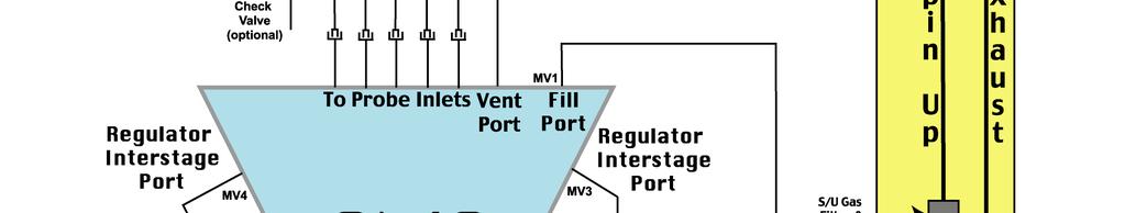
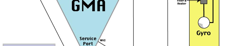
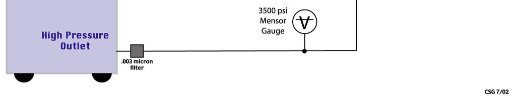
15 G.7 Diagrams Diagram 1, GMA Schematic Zone Zone Zone Zone Zone Zone OMG1 GAS SUPPLY BOTTLE 2000 PSI OMG2 GAS SUPPLY BOTTLE 2000 PSI OMG3 OMG4 Zone OMP1A Outlet Manifold Manual Valve Page 15 of 21
16 Diagram 2, GMA and Space Vehicle Page 16 of 21
17 Diagram 3, Vacuum system Plumbing Spinup outlets P1A outlets DP1 Leak Detector Vent outlet BV1 Leak Detector OMVent Page 17 of 21


18 Diagram 4, GMA and GAF Schematic Page 18 of 21
19 G.8 PRE-TEST CHECKLIST DATE PROCEDURE # CHECKLIST ITEM COMPLETED REMARKS 1. VERIFY THE TEST PROCEDURE BEING USED IS THE LATEST REVISION. 2. VERIFY ALL CRITICAL ITEMS IN THE TEST ARE IDENTIFIED AND DISCUSSED WITH THE TEST TEAM. 3. VERIFY ALL REQUIRED MATERIALS AND TOOLS ARE PRE- STAGED AND AVAILABLE IN THE TEST AREA. 4. VERIFY ALL HAZARDOUS MATERIALS INVOLVED IN THE TEST ARE IDENTIFIED TO THE TEST TEAM. 5. IF HELIUM IS TO BE USED VERIFY THAT A BLUE HELIUM TAG IS AROUND THE NECK OF THE HELIUM CYLINDER. 6. VERIFY ALL HAZARDOUS STEPS TO BE PERFORMED ARE IDENTIFIED TO THE TEST TEAM. 7. VERIFY EACH TEAM MEMBER KNOWS THEIR INDIVIDUAL RESPONSIBILITIES. 8. CONFIRM THAT EACH TEST TEAM MEMBER CLEARLY UNDERSTANDS THAT HE/SHE HAS THE AUTHORITY TO STOP THE TEST IF AN ITEM IN THE PROCEDURE IS NOT CLEAR. NOTE: DURING A HAZARDOUS OPERATION THE TEST WILL ONLY BE STOPPED WHEN IT IS SAFE TO DO SO. 9. CONFIRM THAT EACH TEST TEAM MEMBER CLEARLY UNDERSTANDS THAT HE/SHE HAS THE AUTHORITY TO STOP THE TEST IF THERE IS ANY ANOMALY OR SUSPECTED ANOMALY NOTE: DURING A HAZARDOUS OPERATION THE TEST WILL ONLY BE STOPPED WHEN IT IS SAFE TO DO SO 10. NOTIFY MANAGEMENT OF ALL DISCREPANCY REPORTS OR D-LOG ITEMS IDENTIFIED DURING THE PROCEDURE. IN THE EVENT AN INCIDENT OCCURS DURING PROCEDURE PERFORMANCE, MANAGEMENT WILL BE NOTIFIED IMMEDIATELY. 11. CONFIRM THAT EACH TEST TEAM MEMBER UNDERSTANDS THAT THERE WILL BE A POST-TEST TEAM MEETING. TEAM LEAD SIGNATURE: Page 19 of 21
20 G.9 POST-TEST CHECKLIST DATE PROCEDURE # CHECKLIST ITEM COMPLETED REMARKS 1- VERIFY ALL STEPS IN THE PROCEDURE WERE SUCCESSFULLY COMPLETED. 2- VERIFY ALL MINOR/MAJOR DISCREPANCIES DISCOVERED DURING TESTING ARE PROPERLY DOCUMENTED. 3- ENSURE MANAGEMENT HAS BEEN NOTIFIED OF ALL MINOR/MAJOR DISCREPANCIES. 4- ENSURE THAT ALL STEPS THAT WERE NOT REQUIRED TO BE PERFORMED ARE PROPERLY IDENTIFIED. 5- IF APPLICABLE SIGN-OFF TEST COMPLETION. TEAM LEAD SIGNATURE Page 20 of 21
21 H PROCEDURE SIGN OFF The results obtained in the performance of this procedure are acceptable: Test Director date: Discrepancies if any: Approved: date: C. Gray, GMA REE Approved: date: QA Representative Approved: date: D. Ross, QA Page 21 of 21
BLEED DOWN OF THE HIGH GMA PRESSURE
 SU/GP-B STANFORD UNIVERSITY W.W. HANSEN EXPERIMENTAL PHYSICS LABORATORY GRAVITY PROBE B, RELATIVITY GYROSCOPE EXPERIMENT STANFORD, CALIFORNIA 94305-4085 BLEED DOWN OF THE HIGH GMA PRESSURE GP-B ENGINEERING
STANFORD UNIVERSITY W.W. HANSEN EXPERIMENTAL PHYSICS LABORATORY GRAVITY PROBE B, RELATIVITY GYROSCOPE EXPERIMENT STANFORD, CALIFORNIA
 SU/GP-B P0930 Rev STANFORD UNIVERSITY W.W. HANSEN EXPERIMENTAL PHYSICS LABORATORY GRAVITY PROBE B, RELATIVITY GYROSCOPE EXPERIMENT STANFORD, CALIFORNIA 94305-4085 GMA SLEEP PROCEDURE GP-B ENGINEERING PROCEDURE
TEST OF GMA SPINUP ASSEMBLY PRESSURE SENSOR CALIBRATION
 P0828 Rev. March 14, 2001 STANFORD UNIVERSITY W.W. HANSEN EXPERIMENTAL PHYSICS LABORATORY GRAVITY PROBE B, RELATIVITY GYROSCOPE EXPERIMENT STANFORD, CALIFORNIA 94305-4085 TEST OF GMA SPINUP ASSEMBLY PRESSURE
GMA SLEEP PROCEDURE AT VAFB
 SU/GP-B P0962 Rev STANFORD UNIVERSITY W.W. HANSEN EXPERIMENTAL PHYSICS LABORATORY GRAVITY PROBE B, RELATIVITY GYROSCOPE EXPERIMENT STANFORD, CALIFORNIA 94305-4085 GMA SLEEP PROCEDURE AT VAFB GP-B ENGINEERING
GDS OPERATING PROCEDURE
 SU/GP-B P0886 Rev A 4 September, 2002 STANFORD UNIVERSITY W.W. HANSEN EXPERIMENTAL PHYSICS LABORATORY GRAVITY PROBE B, RELATIVITY GYROSCOPE EXPERIMENT STANFORD, CALIFORNIA 94305-4085 GDS OPERATING PROCEDURE
BLEED DOWN OF THE GMA HIGH PRESSURE AT VAFB
 SU/G-B 0968 Rev - STANFORD UNIVERSITY W.W. HANSEN EXERIMENTAL HYSICS LABORATORY GRAVITY ROBE B, RELATIVITY GYROSCOE EXERIMENT STANFORD, CALIFORNIA 94305-4085 BLEED DOWN OF THE GMA HIGH RESSURE AT VAFB
SCRUB LAUNCH RECOVERY PROCEDURE FOR THE GMA
 SU/GP-B STANFORD UNIVERSITY W.W. HANSEN EXPERIMENTAL PHYSICS LABORATORY GRAVITY PROBE B, RELATIVITY GYROSCOPE EXPERIMENT STANFORD, CALIFORNIA 94305-4085 SCRUB LAUNCH RECOVERY PROCEDURE FOR THE GMA GP-B
CALIBRATING THE GMA PRESSURE SENSORS AND THE ECU ENGINEERING UNIT
 P0807 Rev. STANFORD UNIVERSITY W.W. HANSEN EXPERIMENTAL PHYSICS LABORATORY GRAVITY PROBE B, RELATIVITY GYROSCOPE EXPERIMENT STANFORD, CALIFORNIA 94305-4085 CALIBRATING THE GMA PRESSURE SENSORS AND THE
GMA FUNCTIONAL TEST SETTING & TESTING OF SPIN UP PARAMETERS. P0586 REV -- 20, June 2000 GPB SCIENCE MISSION PROCEDURE
 P0586 Rev. June 20, 2000 STANFORD UNIVERSITY W.W. HANSEN EXPERIMENTAL PHYSICS LABORATORY GRAVITY PROBE B, RELATIVITY GYROSCOPE EXPERIMENT STANFORD, CALIFORNIA 94305-4085 GMA FUNCTIONAL TEST SETTING & TESTING
GMA TO SPACE VEHICLE PLUMBING HOOKUP
 SU/GP-B P0945 Rev 7 October, 2002 STANFORD UNIVERSITY W.W. HANSEN EXPERIMENTAL PHYSICS LABORATORY GRAVITY PROBE B, RELATIVITY GYROSCOPE EXPERIMENT STANFORD, CALIFORNIA 94305-4085 GMA TO SPACE VEHICLE PLUMBING
GMA VENT EXTENSION SERVICE PROCEDURE
 SU/GP-B P0973 Rev STANFORD UNIVERSITY W.W. HANSEN EXPERIMENTAL PHYSICS LABORATORY GRAVITY PROBE B, RELATIVITY GYROSCOPE EXPERIMENT STANFORD, CALIFORNIA 94305-4085 GMA VENT EXTENSION SERVICE PROCEDURE GP-B
GMA PREPARATION FOR E28 TESTING
 SU/G-B 970 Rev 2 January, 2003 STANFORD UNIVERSITY W.W. HANSEN EXERIMENTAL HYSICS LABORATORY GRAVITY ROBE B, RELATIVITY GYROSCOE EXERIMENT STANFORD, CALIFORNIA 94305-4085 GMA REARATION FOR E28 TESTING
STANFORD UNIVERSITY W.W. HANSEN EXPERIMENTAL PHYSICS LABORATORY GRAVITY PROBE B, RELATIVITY GYROSCOPE EXPERIMENT STANFORD, CALIFORNIA
 P0738 Rev. August 14. 2000 SU/GP-B P0738 Rev- STANFORD UNIVERSITY W.W. HANSEN EXPERIMENTAL PHYSICS LABORATORY GRAVITY PROBE B, RELATIVITY GYROSCOPE EXPERIMENT STANFORD, CALIFORNIA 94305-4085 GMA CLEANING
DESIGN VERIFICATION AND QUALIFICATION OF NEW POPPET AND BUSHING ON GMA FLIGHT SOLENOID VALVES
 STANFORD UNIVERSITY W.W. HANSEN EXPERIMENTAL PHYSICS LABORATORY GRAVITY PROBE B, RELATIVITY GYROSCOPE EXPERIMENT STANFORD, CALIFORNIA 94305-4085 DESIGN VERIFICATION AND QUALIFICATION OF NEW POPPET AND
GSE CAGING AND SPINUP BUFFER LINE INSTALLATION
 Stanford University Program Operation Order No. GRAVITY PROBE B PROCEDURE FOR PAYLOAD VERIFICATION GSE CAGING AND SPINUP BUFFER LINE INSTALLATION Sept. 28, 2000 Prepared by: B. Muhlfelder Approvals Program
Vibration/leak Test 2.5 and 6 Vatterfly Valves (3179 and 3223) spare units. GP-B Engineering Procedure P0761 Rev.-
 spare units. GP-B Engineering Procedure P0761 Rev.-") Ops Order No. W. W. Hansen Experimental Physics Laboratory STANFORD UNIVERSITY STANFORD, CALIFORNIA 94305-4085 Gravity Probe B Relativity Mission Vibration/leak Test 2.5 and 6 Vatterfly Valves (3179 and
Ops Order No. W. W. Hansen Experimental Physics Laboratory STANFORD UNIVERSITY STANFORD, CALIFORNIA 94305-4085 Gravity Probe B Relativity Mission Vibration/leak Test 2.5 and 6 Vatterfly Valves (3179 and
GSE CAGING BALLAST SYSTEM INSTALLATION
 Stanford University Gravity Probe B Program Procedure No. P0621 Rev. Operation Order No. GRAVITY PROBE B PROCEDURE FOR PAYLOAD VERIFICATION GSE CAGING BALLAST SYSTEM INSTALLATION October 26, 1999 Prepared
(PTP) PROBE PRESSURE MEASUREMENT SYSTEM INSTALLATION AND LEAK CHECK PROCEDURE
 PROBE PRESSURE MEASUREMENT SYSTEM INSTALLATION AND LEAK CHECK PROCEDURE") Stanford University Gravity Probe B Program Procedure No. P0558 Rev. A Operation Order No. GRAVITY PROBE B PROCEDURE FOR PAYLOAD VERIFICATION (PTP) PROBE PRESSURE MEASUREMENT SYSTEM INSTALLATION AND LEAK
Stanford University Gravity Probe B Program Procedure No. P0558 Rev. A Operation Order No. GRAVITY PROBE B PROCEDURE FOR PAYLOAD VERIFICATION (PTP) PROBE PRESSURE MEASUREMENT SYSTEM INSTALLATION AND LEAK
LOW PRESSURE VOLTAGE BREAKDOWN TEST PROCEDURE FOR GSS FSU FLIGHT SPARE HVA BOARD October 28, P0938 Rev
 W. W. Hansen Experimental Physics Laboratory STANFORD UNIVERSITY STANFORD, CALIFORNIA 94305-4085 Gravity Probe B Relativity Mission LOW PRESSURE VOLTAGE BREAKDOWN TEST PROCEDURE FOR GSS FSU FLIGHT SPARE
PROCEDURE FOR THERMAL CYCLING IN LIQUID NITROGEN
 STANFORD UNIVERSITY W.W. HANSEN EXPERIMENTAL PHYSICS LABORATORY GRAVITY PROBE B, RELATIVITY GYROSCOPE EXPERIMENT STANFORD, CALIFORNIA 94305-4085 P0063 SU/GP-B P0063 PROCEDURE FOR THERMAL CYCLING IN LIQUID
CLEANLINESS TEST OF PROBE SPINUP EXHAUST LINES
 SU/GP-B P0388 Rev STANFORD UNIVERSITY W.W. HANSEN EXPERIMENTAL PHYSICS LABORATORY GRAVITY PROBE B, RELATIVITY GYROSCOPE EXPERIMENT STANFORD, CALIFORNIA 94305-4085 CLEANLINESS TEST OF PROBE SPINUP EXHAUST
CHECK READOUT LOOP CONTINUITY IN PROBE C
 P0726 August 02, 2000 STANFORD UNIVERSITY W.W. HANSEN EXPERIMENTAL PHYSICS LABORATORY GRAVITY PROBE B, RELATIVITY GYROSCOPE EXPERIMENT STANFORD, CALIFORNIA 94305-4085 CHECK READOUT LOOP CONTINUITY IN PROBE
Proton Monitor Thermal Vacuum Test Procedure GP-B P0635
 Procedure Number P0635 Rev Page Count: 7 W. W. Hansen Experimental Physics Laboratory STANFORD UNIVERSITY STANFORD, CALIFORNIA 94305-4085 Gravity Probe B Relativity Mission Proton Monitor Thermal Vacuum
GUARD TANK PRESSURIZATION FOR TRANSPORT
 Stanford University P0801 Rev. January 18, 2001 Operation No. GRAVITY PROBE-B PAYLOAD TESTING PROCEDURE GUARD TANK PRESSURIZATION FOR TRANSPORT P0801 Rev- January 18, 2001 Prepared by Jim Maddocks Cryogenic
PROBE-C CAGING VALVE INSTALLATION
 SU/GP-B STANFORD UNIVERSITY W.W. HANSEN EXPERIMENTAL PHYSICS LABORATORY GRAVITY PROBE B, RELATIVITY GYROSCOPE EXPERIMENT STANFORD, CALIFORNIA 94305-4085 PROBE-C CAGING VALVE INSTALLATION GP-B SCIENCE MISSION
(PTP) REMOVE PROBE SPINUP GAS/VAC. LINES (HORIZ.)
 REMOVE PROBE SPINUP GAS/VAC. LINES (HORIZ.)") Stanford University Gravity Probe B Program Procedure No. P0647 Rev. A Operation Order No. GRAVITY PROBE B PROCEDURE FOR PAYLOAD VERIFICATION (PTP) REMOVE PROBE SPINUP GAS/VAC. LINES (HORIZ.) Prepared
Stanford University Gravity Probe B Program Procedure No. P0647 Rev. A Operation Order No. GRAVITY PROBE B PROCEDURE FOR PAYLOAD VERIFICATION (PTP) REMOVE PROBE SPINUP GAS/VAC. LINES (HORIZ.) Prepared
ASSEMBLY OF GAS FLOW HARDWARE INTO SM GMA
 SU/GP-B P0578 Rev STANFORD UNIVERSITY W.W. HANSEN EXPERIMENTAL PHYSICS LABORATORY GRAVITY PROBE B, RELATIVITY GYROSCOPE EXPERIMENT STANFORD, CALIFORNIA 94305-4085 ASSEMBLY OF GAS FLOW HARDWARE INTO SM
IEP SENSOR BRACKET CHECKOUT AND VERIFICATION. This is a non-hazardous test.
 Page 1 of 20 NEXT GENERATION GAS SYSTEM (NGGS ) IEP SENSOR BRACKET CHECKOUT AND VERIFICATION PROCEDURE 870-PROC-623 Revision A Goddard Space Flight Center Greenbelt, Maryland 20771 FEBRUARY 13, 2002 This
POROUS PLUG CHARACTERIZATION TEST
 Page 1 of 28 GRAVITY PROBE B PROCEDURE FOR PAYLOAD VERIFICATION POROUS PLUG CHARACTERIZATION TEST Prepared by: Rose LaLanne PROCEDURE NO. P0537 REV. - 05/28/99 Approvals Program Responsibility Signature
PROCEDURE TO MEASURE READOUT LOOP RESISTANCE
 Stanford University Gravity Probe B Program October 19, 1998 GRAVITY PROBE B PROCEDURE FOR GYROSCOPE COMMISIONING P0426 REV. - PROCEDURE TO MEASURE READOUT LOOP RESISTANCE Prepared by: Robert W. Brumley
PREPARE FOR CRYO OPS FOLLOWING TRANSPORT TO B1610 To be performed at Vandenberg Air Force Base building 1610
 Stanford University ` Program Op. Order No. GRAVITY PROBE B PROCEDURE FOR SCIENCE MISSION DEWAR PREPARE FOR CRYO OPS FOLLOWING TRANSPORT TO B1610 To be performed at Vandenberg Air Force Base building 1610
Proto-qual Vibration Test Procedure 2.5 and 6 Vacuum Valves (3179 and 3223) Retest of Flight Spare Valves. GP-B P0735 Rev.-
 Retest of Flight Spare Valves. GP-B P0735 Rev.-") P0735Rev. August 09, 2000 W. W. Hansen Experimental Physics Laboratory STANFORD UNIVERSITY STANFORD, CALIFORNIA 94305-4085 Gravity Probe B Relativity Mission Proto-qual Vibration Test Procedure 2.5 and
P0735Rev. August 09, 2000 W. W. Hansen Experimental Physics Laboratory STANFORD UNIVERSITY STANFORD, CALIFORNIA 94305-4085 Gravity Probe B Relativity Mission Proto-qual Vibration Test Procedure 2.5 and
GRAVITY PROBE B PROCEDURE FOR SCIENCE MISSION DEWAR. Spacecraft Battery Magnetic Field Survey
 Stanford University GRAVITY PROBE B PROCEDURE FOR SCIENCE MISSION DEWAR Spacecraft Battery Magnetic Field Survey This operation to be performed in VAFB building 1610 THIS DOCUMENT CONTAINS NON-HAZARDOUS
GRAVITY PROBE B PROCEDURE FOR SCIENCE MISSION DEWAR. Prepare Payload for Mass/CG Measurements and Condition Payload During Spin Balance Test
 Stanford University GRAVITY PROBE B PROCEDURE FOR SCIENCE MISSION DEWAR and Condition Payload During Spin Balance Test THIS DOCUMENT CONTAINS THE USE OF HAZARDOUS MATERIALS Rev. - Jan 20, 2003 Written
GRAVITY PROBE B PROCEDURE FOR SCIENCE MISSION DEWAR DISCONNECT MAIN TANK VENT LINE FROM GAS MODULE MAIN TANK SUBATMOSPHERIC
 Stanford University May 08, 2000 GRAVITY PROBE B PROCEDURE FOR SCIENCE MISSION DEWAR DISCONNECT MAIN TANK VENT LINE FROM GAS MODULE MAIN TANK SUBATMOSPHERIC May 8, 2000 Prepared by: Date Jim Maddocks Cryogenic
GRAVITY PROBE B PROCEDURE FOR SCIENCE MISSION DEWAR. Install Fill Line Burst Disk on SMD
 Stanford University P0795 RevA GRAVITY PROBE B PROCEDURE FOR SCIENCE MISSION DEWAR Install Fill Line Burst Disk on SMD P0795A ECO# 1311 December 5th, 2001 Revised by: Date Ned Calder Cryogenic Test Checked
GRAVITY PROBE B PROCEDURE FOR SCIENCE MISSION DEWAR. Install Fill Line Relief Assembly on SMD
 Stanford University P0823 Rev. February 26, 2001 Operation No. GRAVITY PROBE B PROCEDURE FOR SCIENCE MISSION DEWAR Install Fill Line Relief Assembly on SMD February 26, 2001 Written by Date Jim Maddocks
Pressurize Well to One Atmosphere with Probe Installed
 Stanford University GRAVITY PROBE B PROCEDURE FOR SCIENCE MISSION DEWAR Pressurize Well to One Atmosphere with Probe Installed ECO 1089 September 25, 2000 Revised by Date Jim Maddocks Cryogenic Test Checked
GRAVITY PROBE B PROCEDURE FOR SCIENCE MISSION DEWAR REGULATE GUARD TANK PRESSURE
 Stanford University P0797 Rev. January 24, 2001 Operation No. GRAVITY PROBE B PROCEDURE FOR SCIENCE MISSION DEWAR REGULATE GUARD TANK PRESSURE January 24, 2001 Written by Date Jim Maddocks Cryogenic Test
DRAFT. Operating Procedures for the NPDGamma Liquid Hydrogen Target in TA-53, Building MPF-35
 Operating Procedures for the NPDGamma Liquid Hydrogen Target V0.03 11/26/05 1 DRAFT Operating Procedures for the NPDGamma Liquid Hydrogen Target in TA-53, Building MPF-35 Version 0.03 November 26, 2005
NPDGamma LH2 Target OJT Lesson Plan: Senior Operator for the NPDGamma LH2 Target Operators
 0. Introduction Object of this on-the-job Training (OJT) Lesson Plan is to train Senior Operators for the NPDGamma LH2 target system. After successful of this OJT and authorization by line management Senior
SEMASPEC Test Method for Determination of Cycle Life of Automatic Valves for Gas Distribution System Components
 SEMASPEC Test Method for Determination of Cycle Life of Automatic Valves for Gas Distribution System Components Technology Transfer 90120395B-STD and the logo are registered service marks of, Inc. 1996,
D R A F T. Operating Procedures for the NPDGamma Liquid Hydrogen Target at the BL 13. Version 1.00
 D R A F T Operating Procedures for the NPDGamma Liquid Hydrogen Target at the BL 13 Version 1.00 October 06, 2010 Operating Procedures for the NPDGamma Liquid Hydrogen Target V1.00 6/10/10 2 Table of Content
GRAVITY PROBE B PROCEDURE FOR SCIENCE MISSION DEWAR STOP PUMPING ON SMD VACUUM SHELL / DISCONNECT VACUUM MODULE
 Stanford University GRAVITY PROBE B PROCEDURE FOR SCIENCE MISSION DEWAR STOP PUMPING ON SMD VACUUM SHELL / DISCONNECT VACUUM MODULE ECO 1293 August 9, 2001 Revised by Date Jim Maddocks Cryogenic Test Checked
AcornVac Vacuum Plumbing Systems - Trouble Shooting Guide
 AcornVac Vacuum Plumbing Systems - Trouble Shooting Guide 1. Accumulators Problem Accumulator is overflowing If Accumulator continues to overflow Correction 1. Push and hold the manual activation button
GRAVITY PROBE B PROCEDURE FOR SCIENCE MISSION DEWAR CONNECT VACUUM MODULE / PUMP ON SMD VACUUM SHELL
 Stanford University P0213D GRAVITY PROBE B PROCEDURE FOR SCIENCE MISSION DEWAR CONNECT VACUUM MODULE / PUMP ON SMD VACUUM SHELL P0213 REV. D ECO 1403 March 13, 2003 Revised by Date Ned Calder Cryogenic
GRAVITY PROBE B PROCEDURE FOR SCIENCE MISSION DEWAR
 Stanford University GRAVITY PROBE B PROCEDURE FOR SCIENCE MISSION DEWAR CONNECT MAIN TANK VENT LINE TO GAS MODULE MAIN TANK SUBATMOSPHERIC June 15, 2000 Prepared by: Date Jim Maddocks Cryogenic Test Checked
CERTIFICATION OF THE TEMPERATURE MONITOR AND ALARM
 GRAVITY PROBE-B PROCEDURE FOR SCIENCE MISSION DEWAR CERTIFICATION OF THE TEMPERATURE MONITOR AND ALARM To be performed at Vandenberg Air Force Base building 1610/MST THIS DOCUMENT CONTAINS NON HAZARDOUS
Annual Inspection and Calibration Checklist VAF Oilcon MK-6(M) MEPC.108(49) Page 1 of 5
 MEPC.108(49) Page 1 of 5") Page 1 of 5 Vessel Name: Serial number MCU: Serial Number EPU: Serial Number Skid: Mains Supply: V AC @ Hz Software version MCU: Software version EPU: K-factor Cell: K-factor Skid Flowmeter: P/L Maximum
Page 1 of 5 Vessel Name: Serial number MCU: Serial Number EPU: Serial Number Skid: Mains Supply: V AC @ Hz Software version MCU: Software version EPU: K-factor Cell: K-factor Skid Flowmeter: P/L Maximum
Reduce Liquid Level in Main Tank- Liquid at NBP To be performed at Vandenberg Air Force Base building 1610
 Stanford University GRAVITY PROBE B PROCEDURE FOR SCIENCE MISSION DEWAR Reduce Liquid Level in Main Tank- Liquid at NBP To be performed at Vandenberg Air Force Base building 1610 This document contains
HYDROSTATIC LEAK TEST PROCEDURE
 This information is proprietary and shall not be disclosed outside your organization, nor shall it be duplicated, used or disclosed for purposes other than as permitted under the agreement with Kinetics
STANDARD OPERATING PROCEDURES
 PAGE: 1 of 9 CONTENTS 1.0 SCOPE AND APPLICATION 2.0 METHOD SUMMARY 3.0 SAMPLE PRESERVATION, CONTAINERS, HANDLING AND STORAGE 3.1 Canister Receipt 3.2 Canister Storage 4.0 INTERFERENCE AND POTENTIAL PROBLEMS
R I T. Title: STS ASE Semiconductor & Microsystems Fabrication Laboratory Revision: Original Rev Date: 01/21/ SCOPE 2 REFERENCE DOCUMENTS
 Approved by: Process Engineer / / / / Equipment Engineer 1 SCOPE The purpose of this document is to detail the use of the STS ASE. All users are expected to have read and understood this document. It is
OPERATION OF LIQUID PARTICLE COUNTER. GP-B P0045 Rev -
 1 W. W. Hansen Experimental Physics Laboratory STANFORD UNIVERSITY STANFORD, CALIFORNIA 94305-4085 Gravity Probe B Relativity Mission OPERATION OF LIQUID PARTICLE COUNTER GP-B P0045 Rev - May 23, 1997
GRAVITY PROBE B PROCEDURE FOR SCIENCE MISSION DEWAR. Configure SMD for Transport to SLC-2W To be performed at Vandenberg Air Force Base building 1610
 Stanford University Op. No. GRAVITY PROBE B PROCEDURE FOR SCIENCE MISSION DEWAR Configure SMD for Transport to SLC-2W To be performed at Vandenberg Air Force Base building 1610 THIS DOCUMENT DOES NOT CONTAIN
E2.14 Control of Hazardous Energy. Effective Date: 03/01/2018
 University Policy Volume E2: Environment, Health, Safety and Security E2.14 Control of Hazardous Energy Responsible Office: Facilities Management Responsible Officer: Safety Officer POLICY STATEMENT All
LAKOS Waterworks. PWC Series Sand Separators. Installation & Operation Manual LS-829 (10/12)
") LAKOS Waterworks PWC Series Sand Separators Installation & Operation Manual LS-829 (10/12) Table of Contents Separator Operation... 3 Individual Model Details.... 4 Flow vs. Pressure Loss Chart 4 Installation
LAKOS Waterworks PWC Series Sand Separators Installation & Operation Manual LS-829 (10/12) Table of Contents Separator Operation... 3 Individual Model Details.... 4 Flow vs. Pressure Loss Chart 4 Installation
CO 2. (R744) Service Station Presentation. Contents. Goals Basic functions Specification Recovery R477 Vacuum Charge Safety Other features Prototype
 Service Station Presentation. Contents. Goals Basic functions Specification Recovery R477 Vacuum Charge Safety Other features Prototype") (R744) Service Station Presentation Contents Goals Basic functions Specification Recovery R477 Vacuum Charge Safety Other features Prototype Page 1 (R744) Service Station Goals Usability Full automatic
(R744) Service Station Presentation Contents Goals Basic functions Specification Recovery R477 Vacuum Charge Safety Other features Prototype Page 1 (R744) Service Station Goals Usability Full automatic
OPERATING INSTRUCTIONS
 OPERATING INSTRUCTIONS MODEL GS2000 / GS2001 OIL-LESS REFRIGERANT RECOVERY UNIT NATIONAL REFRIGERATION PRODUCTS 985 WHEELER WAY LANGHORNE, PA 19047 (215) 638-8909 FAX (215) 638-9270 R01099 GS2000.DOC NRP-OM-GS2000
Inert Air (N2) Systems Manual
 Systems Manual") INSTRUCTION MANUAL Inert Air (N2) Systems Manual N2-MANUAL 2.10 READ AND UNDERSTAND THIS MANUAL PRIOR TO OPERATING OR SERVICING THIS PRODUCT. GENERAL INFORMATION Positive pressure nitrogen gas pressurizing
INSTRUCTION MANUAL Inert Air (N2) Systems Manual N2-MANUAL 2.10 READ AND UNDERSTAND THIS MANUAL PRIOR TO OPERATING OR SERVICING THIS PRODUCT. GENERAL INFORMATION Positive pressure nitrogen gas pressurizing
Constant Pressure Inlet (CCN) Operator Manual
 Operator Manual") Constant Pressure Inlet (CCN) Operator Manual DOC-0125 Revision J 2545 Central Avenue Boulder, CO 80301-5727 USA C O P Y R I G H T 2 0 1 1 D R O P L E T M E A S U R E M E N T T E C H N O L O G I E S, I
Constant Pressure Inlet (CCN) Operator Manual DOC-0125 Revision J 2545 Central Avenue Boulder, CO 80301-5727 USA C O P Y R I G H T 2 0 1 1 D R O P L E T M E A S U R E M E N T T E C H N O L O G I E S, I
Piped Air SCBA Refilling System Standard
 WALT WHITE Fire Chief 5770 Freeport Blvd., Suite 200 Sacramento, CA 95822-3516 Ph: (916) 808-1300 Fax: (916) 808-1629 www.sacfire.org Piped Air SCBA Refilling System Standard SCOPE: This specification
PUMP DOWN MAIN TANK TO SUBATMOSPHERIC CONDITION
 Stanford University GRAVITY PROBE B PROCEDURE FOR SCIENCE MISSION DEWAR PUMP DOWN MAIN TANK TO SUBATMOSPHERIC CONDITION ECO 1093 June 21, 2000 Revised by Date Jim Maddocks Cryogenic Test Checked by Date
The latest automotive systems require innovative leak test methods and fixturing.
 Leak Testing Auto Parts The latest automotive systems require innovative leak test methods and fixturing. In the past, automobile manufacturers only required basic forms of leak testing to check standard
Significant Change to Dairy Heat Treatment Equipment and Systems
 Significant to Dairy Heat Treatment September 2008 Page 1 Significant to Dairy Heat Treatment Equipment and Systems September 2008 1 Background Requirements for the assessment of dairy heat treatment equipment
INSTRUCTION MANUAL. FLOW CONTROL DRAWERS MANUAL / PLC CONTROL SERIES Model Version Perma Pure LLC Tel:
 PERMA PURE INSTRUCTION MANUAL FLOW CONTROL DRAWERS MANUAL / PLC CONTROL SERIES Model 3300 Version 4.06 Perma Pure LLC Tel: 732-244-0010 P.O. Box 2105, 8 Executive Drive Tel: 800-337-3762 (toll free US)
Early evap monitors. Photo courtesy Toyota Motor Sales, U.S.A., Inc.; diagram courtesy University of Toyota
 Early evap monitors checked for leaks greater than.040 in. (1mm), but starting in model year 2000, the allowable leak was reduced to.020 in. (.5mm), which was phased in over several years. The reduced
Gas Cabinets and Valve Manifold Boxes: Applying CGA G13- Rev 2015 to Gas Delivery Equipment
 Gas Cabinets and Valve Manifold Boxes: Applying CGA G13- Rev 2015 to Gas Delivery Equipment The Standard Governing the Storage & Use of Silane: Compressed Gas Association s Publication CGA G-13 2015: Storage
GRAVITY PROBE B PROCEDURE FOR SCIENCE MISSION DEWAR
 Stanford University GRAVITY PROBE B PROCEDURE FOR SCIENCE MISSION DEWAR CONNECT VACUUM MODULE / PUMP ON SMD VACUUM SHELL To be performed in Vandenberg Air Force Base building 1610 WARNING: This document
American Society of Sanitary Engineering PRODUCT (SEAL) LISTING PROGRAM
 LISTING PROGRAM") American Society of Sanitary Engineering PRODUCT (SEAL) LISTING PROGRAM ASSE STANDARD #1048 - REVISED: 2009 Double Check Detector Fire Protection Backflow Prevention Assemblies Separate, complete laboratory
American Society of Sanitary Engineering PRODUCT (SEAL) LISTING PROGRAM ASSE STANDARD #1048 - REVISED: 2009 Double Check Detector Fire Protection Backflow Prevention Assemblies Separate, complete laboratory
Hazards associated with the gas system and how to mitigate them
 Hazards associated with the gas system and how to mitigate them Do not enter the gas shack if the rotating red light at the entrance is on. This warns of an oxygen deficiency. In General the Gas Mixing
Compiled by: B Beard. Approved by: SH Carstens. Description of requirements and procedures for compact provers to be used as verification standards.
 1. Scope Description of requirements and procedures for compact provers to be used as verification standards. 2. Reference documents Trade Metrology Act SANS1698 3. Policy A. BASIC REQUIREMENTS Compact
Ag Leader Technology Proportional Valve
 NOTE: Indented items indicate parts included in an assembly listed above Part Name/Description Part Number Quantity Valve Assembly Open-Center 4003819 Manifold Open-Center 4003816 1 Valve Parker D3FW 4003818
The Discussion of this exercise covers the following points:
 Exercise 5-3 Wet Reference Leg EXERCISE OBJECTIVE Learn to measure the level in a vessel using a wet reference leg. DISCUSSION OUTLINE The Discussion of this exercise covers the following points: Measuring
GRAVITY PROBE B PROCEDURE FOR SCIENCE MISSION DEWAR MAIN TANK SUBATMOSPHERIC FILL FROM NBP SUPPLY DEWAR GUARD TANK PRECOOL
 Stanford University GRAVITY PROBE B PROCEDURE FOR SCIENCE MISSION DEWAR MAIN TANK SUBATMOSPHERIC FILL FROM NBP SUPPLY DEWAR GUARD TANK PRECOOL April 24, 2001 Prepared by Date Jim Maddocks Cryogenic Test
Lockout/Tagout Training Overview. Safety Fest 2013
 Lockout/Tagout Training Overview Safety Fest 2013 Purpose of Lockout/Tagout The standard covers the servicing and maintenance of machine and equipment in which the unexpected energization or start up of
GRAVITY PROBE B PROCEDURE FOR SCIENCE MISSION DEWAR. Upright SMD (Rotate from Horizontal to Vertical Orientation)
") Stanford University GRAVITY PROBE B PROCEDURE FOR SCIENCE MISSION DEWAR Upright SMD (Rotate from Horizontal to Vertical Orientation) ECO 1291 August 8 2001 Prepared by Date Jim Maddocks Cryogenic Test
Stanford University GRAVITY PROBE B PROCEDURE FOR SCIENCE MISSION DEWAR Upright SMD (Rotate from Horizontal to Vertical Orientation) ECO 1291 August 8 2001 Prepared by Date Jim Maddocks Cryogenic Test
HumiSys HF High Flow RH Generator
 HumiSys HF High Flow RH Generator Designed, built, and supported by InstruQuest Inc. Versatile Relative Humidity Generation and Multi-Sensor System The HumiSys HF is a high flow version of the previously
American Society of Sanitary Engineering PRODUCT (SEAL) LISTING PROGRAM
 LISTING PROGRAM") American Society of Sanitary Engineering PRODUCT (SEAL) LISTING PROGRAM ASSE STANDARD #1019 - REVISED: 2011 Wall Hydrant with Backflow Protection and Freeze Resistance MANUFACTURER: CONTACT PERSON: E-MAIL:
American Society of Sanitary Engineering PRODUCT (SEAL) LISTING PROGRAM ASSE STANDARD #1019 - REVISED: 2011 Wall Hydrant with Backflow Protection and Freeze Resistance MANUFACTURER: CONTACT PERSON: E-MAIL:
Exercise 5-2. Bubblers EXERCISE OBJECTIVE DISCUSSION OUTLINE. Bubblers DISCUSSION. Learn to measure the level in a vessel using a bubbler.
 Exercise 5-2 Bubblers EXERCISE OBJECTIVE Learn to measure the level in a vessel using a bubbler. DISCUSSION OUTLINE The Discussion of this exercise covers the following points: Bubblers How to measure
ASSE International Product (Seal) Listing Program. ASSE Performance Requirements for Air Valve and Vent Inflow Preventer
 Listing Program. ASSE Performance Requirements for Air Valve and Vent Inflow Preventer") ASSE International Product (Seal) Listing Program ASSE 1063-2016 Performance Requirements for Air Valve and Vent Inflow Preventer Manufacturer: Contact Person: E-mail: Address: Laboratory: Laboratory File
ASSE International Product (Seal) Listing Program ASSE 1063-2016 Performance Requirements for Air Valve and Vent Inflow Preventer Manufacturer: Contact Person: E-mail: Address: Laboratory: Laboratory File
Drift-Chamber Gas System Controls Development for the CEBAF Large Acceptance Spectrometer
 Drift-Chamber Gas System Controls Development for the CEBAF Large Acceptance Spectrometer M. F. Vineyard, T. J. Carroll, and M. N. Lack Department of Physics University of Richmond, VA 23173 ABSTRACT The
(PTP) Un-vented Rate of Temperature Rise Using Guard Tank
 Un-vented Rate of Temperature Rise Using Guard Tank") Stanford University Operations No. GRAVITY PROBE B PROCEDURE FOR SCIENCE MISSION DEWAR (PTP) Un-vented Rate of Temperature Rise Using Guard Tank May 22, 2001 Prepared by Date Dave Murray Cryogenic Test
Stanford University Operations No. GRAVITY PROBE B PROCEDURE FOR SCIENCE MISSION DEWAR (PTP) Un-vented Rate of Temperature Rise Using Guard Tank May 22, 2001 Prepared by Date Dave Murray Cryogenic Test
PERFORMANCE SPECIFICATION PROPELLANT, HYDROGEN
 METRIC 17 May 2013 SUPERSEDING MIL-PRF-27201D 07 February 2007 PERFORMANCE SPECIFICATION PROPELLANT, HYDROGEN This specification is approved for use by all Departments and Agencies of the Department of
Vacuum Pumpdown and Venting Procedure, CRaTER Thermal Vacuum System. Dwg. No
 Rev. ECO Description Checked Approval Date 01 32- Release M. Smith Vacuum Pumpdown and Venting Procedure, CRaTER Thermal Vacuum System Dwg. No. 32-06003.05 Revision 01 June 18, 2007 1 1. Introduction 1.1.
NGP-250/500 Nitrogen Generator Quick Start Guide
 NGP-250/500 Nitrogen Generator Quick Start Guide Version: A July 2013 Potter Electric Signal Company, LLC 5757 Phantom Dr., Suite 125 P. O. Box 42037 Hazelwood, MO 63042 Phone: (314) 595-6900 Document
OPERATION MANUAL BFX-2
 OPERATION MANUAL BFX-2 Brake Fluid Exchanger IMPORTANT Test drive vehicle after service to verify proper brake system performance. MAHLE Aftermarket Inc., Service Solutions 10 Innovation Drive York, PA
FE Petro vs. New Red Jacket Competitive Comparison
 FE Petro vs. New Red Jacket Competitive Comparison Price & Performance Comparison 1-1/2 HP FE Petro vs. New Red Jacket 140 120 1-1/2 HP Fixed Speed Pump Performance FE Petro STP150 "New" Red Jacket P150U1
IMPROVED XENON LOADING EQUIPMENT WITH LOADING CAPACITY UP TO 1200 KG FOR ALPHABUS
 IMPROVED XENON LOADING EQUIPMENT WITH LOADING CAPACITY UP TO 1200 KG FOR ALPHABUS Patrick BRAVAIS, Roland SALOME +, Cécile GELAS + * AIR LIQUIDE DTA + CNES Toulouse Abstract Plasmic propulsion systems
Every things under control High-Integrity Pressure Protection System (HIPPS)
") Every things under control www.adico.co info@adico.co Table Of Contents 1. Introduction... 2 2. Standards... 3 3. HIPPS vs Emergency Shut Down... 4 4. Safety Requirement Specification... 4 5. Device Integrity
Every things under control www.adico.co info@adico.co Table Of Contents 1. Introduction... 2 2. Standards... 3 3. HIPPS vs Emergency Shut Down... 4 4. Safety Requirement Specification... 4 5. Device Integrity
MASSACHUSETTS STATE POLICE CRIME LABORATORY. Certificate of Calibration Procedure for the Alcotest 9510
 MASSACHUSETTS STATE POLICE CRIME LABORATORY Certificate of Calibration Procedure for the Alcotest 9510 Effective Date: May 10, 2017 Page 1 of 23 TABLE OF CONTENTS 1 INTRODUCTION... 3 2 ABBREVIATIONS...
Proper Pump Installation Practices
 Proper Pump Installation Practices 80-779, Rev. 10/08 There is a Reason Every Unit Comes With This Bright Orange Tag! Proper Alignment and Coupling Installation Do Not Drive Coupling Onto Shaft Pump Alignment
STANDARD OPERATING PROCEDURES
 PAGE: 1 of 14 CONTENTS 1.0 SCOPE AND APPLICATION 2.0 METHOD SUMMARY 3.0 SAMPLE PRESERVATION, CONTAINERS, HANDLING, AND STORAGE 4.0 INTERFERENCES AND POTENTIAL PROBLEMS 5.0 EQUIPMENT/APPARATUS 5.1 Subatmospheric
Canadian Light Source Inc. Vacuum Component Leak Test Technical Procedure
 Canadian Light Source Inc. Vacuum Component Leak Test Technical Procedure CLSI Document 8.7.33.2 Rev. 2 Date: 2006-03-08 Copyright 2006, Canadian Light Source Inc. This document is the property of Canadian
Energy Control Procedures Lockout/Tagout 29 CFR
 Energy Control Procedures Lockout/Tagout 29 CFR 1910.147 Paul Schlumper, PE, CSP Georgia Tech Research Institute What is covered? Servicing and maintenance Normal production operations where: Employees
LESER Deutschland Standard Functional Tightness Test (Cryo) Content
 Content") Page 1/10 Content 1 Purpose... 1 2 Scope... 1 3 Range of Application... 1 4 Normative Background... 2 5 Terms and Definitions... 2 6 Test Equipment... 3 7 Test Procedure... 5 8 Acceptance Criteria... 8
Page 1/10 Content 1 Purpose... 1 2 Scope... 1 3 Range of Application... 1 4 Normative Background... 2 5 Terms and Definitions... 2 6 Test Equipment... 3 7 Test Procedure... 5 8 Acceptance Criteria... 8
Instructions for Assembly, Installation, and Operation of the Gas Addition Kit Accessory with the CEM Discover Systems
 Corporation Issued: 5/09 P/N: 600104 Rev. 2 Instructions for Assembly, Installation, and Operation of the Gas Addition Kit Accessory with the CEM Discover Systems The Gas Addition Accessory permits the
API MPMS Chapter 17.6 Guidelines for Determining the Fullness of Pipelines between Vessels and Shore Tanks
 API MPMS Chapter 17.6 Guidelines for Determining the Fullness of Pipelines between Vessels and Shore Tanks 1. Scope This document describes procedures for determining or confirming the fill condition of
1020 Industrial Drive, Orlinda, TN fax
 Operation Manual Ultrafiltration for High Purity Distribution K-A-HPTUF Series 615-654-4441 sales@specialtyh2o.com 615-654-4449 fax TABLE OF CONTENTS Section 1 GENERAL 1.1 Warnings and Cautions... 1 1.2
NO SMOKING WHEN OXYGEN IS IN USE.
 GENERAL NO SMOKING WHEN OXYGEN IS IN USE. The oxygen system provides oxygen as required for up to 19 passengers and 2 cockpit crew members. Therapeutic oxygen outlets are also available in the cabin. OXYGEN