During the research and realisation of new products, CSA has always focused his efforts on: - Listening to the customer s needs and finding the best
|
|
|
- Godwin Robert Nicholson
- 5 years ago
- Views:
Transcription

1 Water air valves


2 The company was founded in 987 by transforming the former CSA, which was a trading company dealing with pipes and valves for water networks, into a manufacturing company, through the research and realization of pillar fire hydrants. These were compliant with the UNI 948 regulation, which was at the approval stage. Since then many other products have been added. The history of our company is characterised by years of technical and coercial research, which have enabled us to offer a complete range of valves designed for controlling, regulating and protecting the pipelines under pressure in both waterworks and sewage lines as well as fire hydrants. Our many industrial patents and innovative technical solutions, together with modern and attractive style of design, have made it possible to differentiate our products from those offered by competitors and have allowed us to become a point of reference in our sector. Flexibility and reliability have been the key points of CSA s rapid growth over the last few years. We are perfectly aware that we are managing the world s most precious resource and, motivated by this responsibility and the coitment towards our customers, we have dedicated ourselves to constantly improving our products, placing them at the highest levels of quality. Quality In the manufacturing business today, quality is the fundamental requirement for achieving and maintaining a growing market share. For this reason we have always aimed at developing a synergy between the various sectors of the company and thus ensuring: - Quick and precise answers; - Evaluation of data received and iediate response; -Rigorous control of incoming and outgoing products. Since 998 CSA is certified according to regulation ISO 900 by RINA (Italian Naval Registry) recently converted into ISO 900/2008.


3 During the research and realisation of new products, CSA has always focused his efforts on: - Listening to the customer s needs and finding the best solution both at the design and operational phases. - Guiding our R&D department to develop ranges of modern, reliable and complementary products. - Adopting production techniques that, even while complying with the severest quality standards, would allow us to reduce delivery times. - Guaranteeing complete technical support for our customers and prompt after-sales assistance. This philosophy characterizes us not only as a valve manufacturer but also as a reliable partner whom you can always depend on for consulting and solutions. The production cycle, aimed at the constant improvement of our products and complete customer satisfaction, ensures predetermined margins of tolerance by establishing production standards, which guarantee that the semi finished products reach the next production stage with the required specifications. All our valves are made of ductile cast iron GJS 400- / 00-7 in absolute compliance with European standards, and are suitable for PN 2-40 bar. The manufacturing process is carried out exclusively by means of numerically controlled lathes, mills, and horizontal machining units. Subsequent step-by-step controls are based on strict quality procedures. Painting, pre-treated by sand blasting grade SA 2., is carried out inside a fluidized bed containing epoxy powder, which guarantees maximum surface protection. All our products are tested under water pressure and certified. 3
4 Combination air valve Mod. FOX 3F The CSA air valve Mod. FOX 3F will ensure the proper operation of the pipeline network allowing the release of air pockets during working conditions, the evacuation and entrance of large volumes of air during filling and draining operations. Technical features and benefits Body in ductile cast iron, PN 40 bar rated, provided with internal ribs for consistent and accurate guiding of the mobile block. In general supplied with fixed flanges and, for some DN only, mobile flanges (according to EN 92/2) that can be changed to suit different pressure conditions. Drainage valve, produced by CSA, for chamber control and pressure relief during maintenance. Mobile block composed of a cylindrical float and upper disk in solid polypropylene, joined together by the CSA air release system in AISI 36 (pat. Pending). The solid cylindrical floats, obtained by CNC machining, avoid deformations and ensure a great sliding precision inside the body processed ribs and a perfectly vertical thrust. Nozzle and gasket holder, part of CSA air release system, entirely made in AISI 36 and designed with gasket compression control to prevent aging process and consequent leakage during working conditions. Maintenance can be easily performed from the top, without removing the air valve from the pipe. Mesh and cap in for the M version only. Applications Main transmission lines. Water distribution networks. Irrigation systems. In general this model is used on changes in slope descending and at the high points of the pipeline.

5 Operating principle Discharge of large volumes of air During the pipe filling it is necessary to discharge air as water flows in. The FOX 3F, thanks to an aerodynamic full port body and deflector, will make sure to avoid premature closures of the mobile block during this phase. Optional Air release during working conditions During operation the air produced by the pipeline is accumulated in the upper part of the air valve. Little by little it is compressed and the pressure arrives to water pressure, therefore its volume increases pushing the water level downwards allowing the air release through the nozzle. Entrance of large volumes of air During pipeline draining, or pipe bursts, it is necessary to bring in as much air as the quantity of outflowing water to avoid negative pressure and serious damages of the pipeline, and to the entire system. Vacuum breaker version Mod. FOX 2F, to allow the entrance and discharge of large volumes of air only. This model is normally recoended in changes in slope ascending, long ascending segments, dry fire systems, and wherever the air release won t be required. Version for submerged applications, SUB series, available both for FOX 3F and 2F Models, with elbow for air conveyance. The design sprang from the necessity of having an air valve performing also in case of flood, without the risk of contaminated water entering the pipeline. Another benefit of SUB is to avoid the spray effect, conveying spurts coming from the rapid closure of the air valve. Version for air discharge only EO series, available both for FOX 3F and 2F models. The most important application of EO is to allow the air valve installation in those locations of the system where HGL may drop below the pipe profile, and to any other node where for project requirements air entrance must be avoided. Version for air entrance only IO series, available for FOX 2F model only. The most important application of IO is to allow the air valve installation in those locations of the system where, for project requirements, air discharge and release must be avoided.
6 Air flow performance charts AIR DISCHARGE DURING PIPE FILLING bar DN DN2 /0/6 DN80,,4 DN0 DN0R,3,2,,0 0, m3/h 0,9 0,8 0,7 0,6 bar O / O,2 / O, / O,8 / , DN DN2 /0/6 DN80 DN0 AIR ENTRANCE DURING PIPE DRAINING DN0R Q (nl/s) AIR RELEASE DURING WORKING CONDITIONS AIR DISCHARGE DURING PIPE FILLING bar DN0/200R DN200/20R DN20/300R, DN300/30R DN30/400R,4,3,2,, m 3 /h,0 0,9 0,8 0,7 0,6 bar O2,4 / O3,0 / O4,0 / 0, DN0/200R DN200/20R DN20/300R DN300/30R AIR ENTRANCE DURING PIPE DRAINING DN30/400R Q (nl/s) AIR RELEASE DURING WORKING CONDITIONS Working conditions Treated water max. 60 C; Max. pressure 40 bar; Min. pressure 0,3 bar; Low pressure version to 0,9 bar on request. Standard Designed in compliance with EN-74/4 and AWWA C-2. Flanges according to EN 92/2. Epoxy painting applied through fluidized bed technology blue RAL 00. Changes and variations on the flanges and painting details available on request. CONNECTION inch/ Threaded Threaded 2 Flanged 0 Flanged 6 Flanged 80 Flanged 0 Flanged 0R Flanged 0 Flanged 200R Flanged 200 Flanged 20R Flanged 20 Flanged 300R Flanged 300 Flanged 30R Flanged 30 Flanged 400R A B C* C** D Weight Kg = = CH 4 3, = = CH 7 6, = 8, = 8, =, = 8, = 34, = 49, =, = 94, = 400 = 2, = 40 = 2, = 48 = 27, = = 240, = 80 = 20, = 80 = 29, = 660 = 304,0 B A C * M.F. = mobile flanges version ** F.F. = fixed flanges version D
7 Technical details Version with cap and mesh in, M series, available from up to DN Version with cap in ductile, C series, available from up to DN 0. N. Component Material Standard Body Cap O-ring O-ring Seat Nozzle Subset Upper flat Float Studs Bolts Washer Diffuser Screws Drain valve Spacers Filter ductile cast iron / ductile cast iron NBR NBR polypropylene polypropylene GJS 00-7 / GJS 00-7 AISI 36 A2/A4/AISI 36 A2/A4/AISI 36 A2/A4/AISI 36 A2/A4/AISI 36 AISI 304
8 Anti water haer combination air valve Mod. FOX 3F - AS The CSA air valve Mod. FOX 3F AS will ensure the proper operation of the pipeline network allowing the release of air pockets during working conditions, the entrance of large volumes of air during draining operations and pipeline bursts and the air discharge with controlled speed, to prevent water haer. Technical features and benefits Body in ductile cast iron, PN 40 bar rated, provided with internal ribs for consistent and accurate guiding of the mobile block. Drainage valve produced by CSA, for chamber control and pressure relief during maintenance. Mobile block composed of a cylindrical float and upper disk in solid polypropylene, joined together by the CSA air release system in AISI 36 (pat. Pending). The solid cylindrical floats, obtained by CNC machining only, avoid deformations and ensure a great sliding precision inside the body processed ribs and a perfectly vertical thrust. Nozzle and gasket holder, part of CSA air release system, entirely made in AISI 36 and designed with gasket compression control to prevent aging process and consequent leakage during working conditions. Maintenance can be easily performed from the top, without removing the air valve from the pipe. Anti water haer system (also called AS function), never in contact with water, obtained by a spring and shaft in, disk with adjustable sonic nozzles for air flow control. Applications Main transmission lines. Water distribution networks. Irrigation systems. In general this model is used near pumps, on changes in slope ascending, and at the high points of the pipeline subjected to water haer.


9 Operating principle Controlled air discharge During the pipe filling it is necessary to avoid rapid closures, responsible of water haer effects. The FOX 3F AS, thanks to the anti-shock feature, will control the air outflow thus reducing the velocity of the approaching water column. The risk of overpressure will therefore be minimized. Optional Air release during working conditions During operation the air produced by the pipeline is accumulated in the upper part of the air valve. Little by little it is compressed and the pressure arrives to water pressure, therefore its volume increases pushing the water level downwards allowing the air release through the nozzle. Entrance of large volumes of air During pipeline draining, or pipe bursts, it is necessary to bring in as much air as the quantity of outflowing water to avoid negative pressure and serious damages of the pipeline, and to the entire system. Vacuum breaker version Mod. FOX 2F AS, to allow the entrance of large volumes of air and the controlled outflow only. This model is normally recoended in changes in slope ascending, long ascending segments, dry fire systems. Version for submerged applications, SUB series, available both for FOX 3F AS and 2F AS Models, with elbow for air conveyance. The design sprang from the necessity of having an air valve performing also in case of flood, without the risk of contaminated water entering the pipeline. Another benefit of SUB is to avoid the spray effect, conveying spurts coming from the closure away from the air valve. The counteracting spring force as well as the sonic nozzles, both responsible of the proper operation of the AS device, can be modified on request according to the project conditions and the transient analysis.
10 Air flow performance charts AIR DISCHARGE DURING PIPE FILLING bar DN DN2 /0/6 DN80,,4 DN0 DN0R,3,2,, m 3 /h m 3 /h,0 0,9 0,8 0,7 0,6 bar O / O,2 / O, / O,8 / , DN DN2 /0/6 DN80 AIR ENTRANCE DURING PIPE DRAINING AIR DISCHARGE DURING PIPE FILLING bar DN0/200R DN200/20R DN20/300R, DN300/30R DN0 DN30/400R DN0R Q (nl/s) AIR RELEASE DURING WORKING CONDITIONS,4,3,2,, m 3 /h m3/h,0 0,9 0,8 0,7 0,6 bar O2,4 / O3,0 / O4,0 / 0, DN0/200R DN200/20R DN20/300R AIR ENTRANCE DURING PIPE DRAINING Working conditions Treated water max. 60 C; Max. pressure 40 bar; Min. pressure 0,3 bar; Low pressure version to 0,9 bar on request. DN300/30R Standard DN30/400R Q (nl/s) AIR RELEASE DURING WORKING CONDITIONS Designed in compliance with EN-74/4 and AWWA C-2. Flanges according to EN 92/2. Epoxy painting applies through fluidized bed technology blue RAL 00. Changes and variations on the flanges and painting details available on request. CONNECTION inch/ Threaded Threaded 2 Flanged 0 Flanged 6 Flanged 80 Flanged 0 Flanged 0R Flanged 0 Flanged 200R Flanged 200 Flanged 20R Flanged 20 Flanged 300R Flanged 300 Flanged 30R Flanged 30 Flanged 400R A B C* C** D Weight Kg = = CH 4 3, = = CH 7 6, = 8, = 8, =, = 8, = 34, = 49, =, = 94, = 400 = 2, = 40 = 2, = 48 = 27, = = 240, = 80 = 20, = 80 = 29, = 660 = 304,0 B A C * M.F. = mobile flanges version ** F.F. = fixed flanges version D

11 Technical details Version with cap and mesh in, M series, available from up to DN Version with cap in ductile, C series, available from up to DN 0. N. Component Material Standard Body Cap O-ring O-ring Seat Nozzle subset Upper flat Float Studs Nuts Washer Diffuser Screws Drainage valve Spacers Filter Nut Spring AS shaft Guiding plate (from DN0R) Guiding nut (from DN0R) AS flat ductile cast iron / ductile cast iron NBR NBR polypropylene polypropylene GJS 00-7 / GJS 00-7 A2/A4 A2/A4 A2/A4 A2/A4 AISI 304

12 Combination air valve with rapid filling preventer mechanism Mod. FOX 3F - RFP The CSA air valve Mod. FOX 3F RFP will ensure the proper operation of the system allowing the release of air pockets during working conditions and the entrance of large volumes of air during draining. In addition to that this model will always maintain the air outflow within a safety limit, without the risk of water haer. Technical features and benefits Uncontrolled pipeline filling operations and transient events will inevitably generate the rapid closure of the air valves installed along the system, with consequent damages. The CSA air valve FOX 3F RFP will automatically adjust the outflow capacity, thus reducing the velocity of the incoming water column minimizing the risk of water haer. The spray effect during closure and the risk of air valve drowning, due to low pressure and possible rapid filling, is avoided. Body in ductile cast iron, PN 40 bar rated, provided with internal ribs for consistent and accurate guiding of the mobile block. Mobile block composed of the main float and upper disk, joined together by the CSA air release system in AISI 36 (pat. pending), and an additional anti surge obturator. Nozzle and gasket holder, part of CSA air release system, entirely made in AISI 36 and designed with gasket compression control to prevent aging process and consequent leakage during working conditions. Applications Main transmission lines. Water distribution networks. Irrigation systems. In general this model is used, in combination with CSA AS technology, on changes in slope and high points of the profile to provide the best air control and safety of the pipeline.

13 Operating principle Discharge of large volumes of air During the pipe filling it is necessary to discharge air as water flows in. The FOX 3F RFP, thanks to an aerodynamic full port body and deflector, will make sure to avoid premature closures of the mobile block during this phase. Air release during working conditions During operation the air produced by the pipeline is accumulated in the upper part of the air valve. Little by little it is compressed and the pressure arrives to water pressure, therefore its volume increases pushing the water level downwards allowing the air release through the nozzle. Controlled outflow If the differential pressure of air, during pipe filling, i n c r e a s e s a b ove a certain value without control there is the risk of water haer and damages to the system. Should that happen the RFP upper float will rise automatically, reducing the outflow and consequently the velocity of the approaching water column. Entrance of large volumes of air During pipeline draining, or pipe bursts, it is necessary to bring in as much air as the quantity of outflowing water to avoid negative pressure and serious damages of the pipeline, and to the entire system. Optional Vacuum breaker version Mod. FOX 2F RFP, to allow the entrance of large volumes of air and the controlled outflow only. This model is normally recoended in changes in slope ascending, long ascending segments, dry fire systems, and wherever the water haer effect has to be reduced without the necessity of air release. Version for submerged applications, SUB series, available both for FOX 3F RFP and 2F RFP Models, with elbow for air conveyance. The design sprang from the necessity of having an air valve performing also in case of flood, without the risk of contaminated water entering the pipeline. Another benefit of SUB is to avoid the spray effect, conveying spurts coming from the closure away from the air valve. Version for air discharge only EO series, available both for FOX 3F and 2F models. The most important application of EO is to allow the air valve installation in those locations of the system where HGL may drop below the pipe profile, and to any other node where for project requirements air entrance must be avoided.
14 Air flow performance charts AIR DISCHARGE DURING PIPE FILLING bar DN DN2 /0/6 DN80 DN0 DN0R,,4,3,2,, m3/h,0 0,9 0,8 0,7 0,6 bar O / O,2 / O, / O,8 / , DN AIR ENTRANCE DURING PIPE DRAINING AIR DISCHARGE DURING PIPE FILLING bar, DN0 /200R DN200 /20R DN20 /300R DN300 /30R DN30 /400R DN2 /0/6 DN80 DN0 DN0R Q (nl/s) AIR RELEASE DURING WORKING CONDITIONS,4,3,2,, m 3 /h,0 0,9 0,8 0,7 0,6 bar O2,4 / O3,0 / O4,0 / 0, AIR ENTRANCE DURING PIPE DRAINING Working conditions Treated water max. 60 C; Max. pressure 40 bar; Min. pressure 0,3 bar; Low pressure version to 0,9 bar on request. DN0 /200R DN200 /20R DN20 /300R DN300 /30R DN30 /400R Standard Q (nl/s) AIR RELEASE DURING WORKING CONDITIONS Designed in compliance with EN-74/4 and AWWA C-2. Flanges according to EN 92/2. Epoxy painting applies through fluidized bed technology blue RAL 00. Changes and variations on the flanges and painting details available on request. CONNECTION inch/ Threaded Threaded 2 Flanged 0 Flanged 6 Flanged 80 Flanged 0 Flanged 0R Flanged 0 Flanged 200R Flanged 200 Flanged 20R Flanged 20 Flanged 300R Flanged 300 Flanged 30R Flanged 30 Flanged 400R A B C* C** D Weight Kg = = CH 4 3, = = CH 7 6, = 8, = 8, =, = 8, = 34, = 49, =, = 94, = 400 = 2, = 40 = 2, = 48 = 27, = = 240, = 80 = 20, = 80 = 29, = 660 = 304,0 B A C * M.F. = mobile flanges version ** F.F. = fixed flanges version D

15 Technical details Version with cap and mesh in, M series, available from up to DN Version with cap in ductile, C series, available from up to DN 0. N. Component Material Standard Body Cap O-ring O-ring Seat Nozzle Subset RFP flat Upper flat Float Studs Bolts Washers Diffuser Screws Drain valve Spacers Filter ductile cast iron / ductile cast iron NBR NBR polypropylene polypropylene polypropylene GJS 00-7 / GJS 00-7 A2/A4 A2/A4 A2/A4 A2/A4 AISI 304
16 Combination air valve Mod. FOX 3F - HP The CSA air valve Mod. FOX 3F HP will ensure the proper operation of the pipeline network allowing the release of air pockets during working conditions, the evacuation and entrance of large volumes of air during filling and draining operations. Technical features and benefits Body in carbon welded steel, PN 64 bar rated, provided with internal spacers for consistent and accurate guiding of the mobile block. In general supplied with fixed flanges according to EN 92/2 or different on request. Mobile block composed of a cylindrical float and upper disk in solid polypropylene, joined together by the CSA air release system in AISI 36 (pat. Pending). The solid cylindrical floats, obtained by CNC machining, avoid deformations and ensure a great sliding precision inside the body processed ribs and a perfectly vertical thrust. Nozzle and gasket holder, part of CSA air release system, entirely made in AISI 36 and designed with gasket compression control to prevent aging process and consequent leakage during working conditions. Maintenance can be easily performed from the top, without removing the air valve from the pipe. Mesh and cap in. Applications Main transmission lines. Mines. Dams and high pressure systems In general this model is used on changes in slope descending and at the high points of the pipeline for those locations exposed to high pressure conditions when ductile cast iron is not acceptable.

17 Operating principle Discharge of large volumes of air During the pipe filling it is necessary to discharge air as water flows in. The FOX 3F HP, thanks to an aerodynamic deflector, will make sure to avoid premature closures of the mobile block during this phase. Optional Air release during working conditions During operation the air produced by the pipeline is accumulated in the upper part of the air valve. Little by little it is compressed and the pressure arrives to water pressure, therefore its volume increases pushing the water level downwards allowing the air release through the nozzle. Entrance of large volumes of air During pipeline draining, or pipe bursts, it is necessary to bring in as much air as the quantity of outflowing water to avoid negative pressure and serious damages of the pipeline, and to the entire system. Vacuum breaker version Mod. FOX 2F HP to allow the entrance and discharge of large volumes of air only. This model is normally recoended in changes in slope ascending, long ascending segments, dry fire systems, and wherever the air release won t be required. Version for submerged applications, SUB series, available both for FOX 3F HP and 2F HP Models, with elbow for air conveyance. The design sprang from the necessity of having an air valve performing also in case of flood, without the risk of contaminated water entering the pipeline. Another benefit of SUB is to avoid the spray effect, conveying spurts coming from the rapid closure of the air valve. Version for air discharge only EO series, available both for FOX 3F HP and 2F HP models. The most important application of EO is to allow the air valve installation in those locations of the system where HGL may drop below the pipe profile, and to any other node where for project requirements air entrance must be avoided. Version for air entrance only IO series, available for FOX 2F HP model only. The most important application of IO is to allow the air valve installation in those locations of the system where, for project requirements, air discharge and release must be avoided.
18 Air flow performance charts AIR DISCHARGE DURING PIPE FILLING BAR, DN DN2 /0/6 DN80 DN0,4,4,3 DN0,3,2,2,,, ,9 0,9 0,8 0,8 0,7 0,7 0,6 0,6 0, BAR 0, DN DN2 /0/6 DN80 DN0 DN0 AIR ENTRANCE DURING PIPE DRAINING m 3 /h Working conditions Treated water 70 C max.; Maximum pressure 64 bar; Minimum pressure 0,2 bar; bar O / O,2 / O, / O,8 / Standard Designed in compliance with EN-74/4. Flanges according to EN 92/2, ANSI. Epoxy painting applied through fluidized bed technology blue RAL 00. Changes and variations on the flanges and painting details available on request Q (nl/s) AIR RELEASE DURING WORKING CONDITIONS A CONNECTION inch/ A B C Weight Kg Threaded Threaded 2 Flanged 0 Flanged 6 Flanged 80 Flanged 0 Flanged , , , , , , ,0 B C

19 Technical details N. Component Material Standard Body Cap O-ring O-ring Seat Nozzle Subset Upper flat Float Nut Washers Screws Screws Drain valve Spacers Filter steel NBR NBR polypropylene polypropylene Fe 37 AISI 36 A2/A4/AISI 36 A2/A4/AISI 36 A2/A4/AISI 36 A2/A4/AISI 36 AISI 304

20 Anti water haer combination air valve Mod. FOX 3F - AS - HP The CSA air valve Mod. FOX 3F AS HP will ensure the proper operation of the pipeline network allowing the release of air pockets during working conditions, the entrance of large volumes of air during draining operations and pipeline bursts and the air discharge with controlled speed, to prevent water haer. Technical features and benefits Body in carbon welded steel, PN 64 bar rated, provided with internal spacers for consistent and accurate guiding of the mobile block. In general supplied with fixed flanges according to EN 92/2 or different on request. Mobile block composed of a cylindrical float and upper disk in solid polypropylene, joined together by the CSA air release system in AISI 36 (pat. Pending). The solid cylindrical floats, obtained by CNC machining only, avoid deformations and ensure a great sliding precision inside the body processed ribs and a perfectly vertical thrust. Nozzle and gasket holder, part of CSA air release system, entirely made in AISI 36 and designed with gasket compression control to prevent aging process and consequent leakage during working conditions. Maintenance can be easily performed from the top, without removing the air valve from the pipe. Anti water haer system (also called AS function), never in contact with water, obtained by a spring and shaft in, disk with adjustable sonic nozzles for air flow control. Applications Main transmission lines. Mines. Dams and high pressure systems. In general this model is used on changes in slope ascending, and at the high points of the pipeline subjected to water haer.

21 Operating principle Controlled air discharge During the pipe filling it is necessary to avoid rapid closures, responsible of water haer effects. The FOX 3F AS HP, thanks to the anti-shock feature, will control the air outflow thus reducing the velocity of the approaching water column. The risk of overpressure will therefore be minimized. Optional Air release during working conditions During operation the air produced by the pipeline is accumulated in the upper part of the air valve. Little by little it is compressed and the pressure arrives to water pressure, therefore its volume increases pushing the water level downwards allowing the air release through the nozzle. Entrance of large volumes of air During pipeline draining, or pipe bursts, it is necessary to bring in as much air as the quantity of outflowing water to avoid negative pressure and serious damages of the pipeline, and to the entire system. Vacuum breaker version Mod. FOX 2F AS HP, to allow the entrance of large volumes of air and the controlled outflow only. This model is normally recoended in changes in slope ascending, long ascending segments, dry fire systems. Version for submerged applications, SUB series, available both for FOX 3F AS HP and 2F AS HP Models, with elbow for air conveyance. The design sprang from the necessity of having an air valve performing also in case of flood, without the risk of contaminated water entering the pipeline. Another benefit of SUB is to avoid the spray effect, conveying spurts coming from the closure away from the air valve. The counteracting spring force as well as the sonic nozzles, both responsible of the proper operation of the AS device, can be modified on request according to the project conditions and the transient analysis.
22 Air flow performance charts AIR DISCHARGE DURING PIPE FILLING BAR, DN DN2 /0/6 DN80 DN0,4,4,3 DN0,3,2,2,,, m 3 /h m 3 /h 0,9 0,9 0,8 0,8 0,7 0,7 0,6 0,6 0, BAR 0, DN DN2 /0/6 DN80 DN0 DN0 AIR ENTRANCE DURING PIPE DRAINING Working conditions Treated water 70 C max.; Maximum pressure 64 bar; Minimum pressure 0,2 bar; bar O / O,2 / O, / O,8 / Standard Designed in compliance with EN-74/4. Flanges according to EN 92/2, ANSI. Epoxy painting applied through fluidized bed technology blue RAL 00. Changes and variations on the flanges and painting details available on request Q (nl/s) AIR RELEASE DURING WORKING CONDITIONS A CONNECTION inch/ A B C Weight Kg Threaded Threaded 2 Flanged 0 Flanged 6 Flanged 80 Flanged 0 Flanged , , , , , , ,0 B C
23 Technical details N. Component Material Standard Body Cap O-ring O-ring Seat Nozzle subset Upper flat Float Screws Nuts Washer Screws Spacers Filter Nut Spring AS shaft Guiding plate (in DN0) Guiding nut (in DN0) AS flat steel NBR NBR polypropylene polypropylene Fe 37 A2/A4/AISI 36 A2/A4/AISI 36 A2/A4/AISI 36 A2/A4/AISI 36 AISI 304

24 Air release valve Mod. VENTOLO The CSA air release valve Ventolo will ensure the proper operation of the system allowing the release of air pockets accumulating during working conditions. Technical features and benefits Body and cover in ductile cast iron, PN 40 bar rated. Float in. Lever and pivots in. Nozzle in. Compass lever technology to allow large air release capacity through the nozzle. Double o-ring to guarantee the perfect water tightness during working conditions. Gasket compression control thanks to the adjustable nozzle. Nuts and bolts in A2/ AISI 36. Minimum working pressure 0, bar. Applications Water distribution systems, irrigation, buildings. Pumps case. Control valves and modulating devices. In general only when the air release function is required, it can be combined with CSA air valves FOX series for the kinetic functions of air outflow and inflow.


25 Technical details N. Component Material Standard Body Cap O-ring Nozzle Nut O-ring Upper lever Pivot Lower lever Nozzle gasket Float Nut Screw Ball valve Flange ductile cast iron ductile cast iron NBR NBR NBR ductile cast iron GJS 00-7 GJS 00-7 AISI 36 AISI 36 GJS 00-7 Working conditions Treated water max. 70 C; Max. pressure 40 bar; Min. pressure 0, bar. Standard Designed in compliance with EN-74/4. Standard connection, flanged on request. Flanges according to EN 92/2. Epoxy painting applies through fluidized bed technology blue RAL 00. Changes and variations on the flanges and painting details available on request. Air flow performance charts p (bar) O, / AIR RELEASE DURING WORKING CONDITIONS O,7 / Q (nl/s)

26 Combination air valve Mod. EOLO The CSA combination air valve Eolo will ensure the proper operation of the system allowing the release of air pockets accumulating during working conditions, the entrance and discharge of large volumes of air during pipe draining and filling. Technical features and benefits Upper and lower bodies in ductile cast iron GJS 00/7 PN 2 rated. Float in AISI 304 covered with vulcanized NBR. Patented air release system with gasket compression control in brass/ AISI 304. Guiding shaft of the air release system in AISI 304. Nuts and bolts in A/2. Simple and compact. Applications Water distribution systems. Irrigation, cooling systems. Buildings. In general where the air release function is necessary along with a certain air flow capacity, limited to the kinetic passage of this model for which please see the air charts on the next page.


27 Technical details N. Component Material Standard Lower body Upper body O-ring Float Nozzle body O-ring Tap Shaft Studs O-ring Screws, washers and bots Ball valve Flange ductile cast iron ductile cast iron NBR /NBR brass/ NBR brass/ brass NBR ductile cast iron GJS 00-7 GJS 00-7 AISI 36 OT 8/ OT 8/ OT 8 AISI 36 GJS 00-7 Working conditions Treated water max. 70 C, higher temperature on request; Max. pressure 2 bar; Min. pressure 0,3 bar. Standard Designed in compliance with EN-74/4. Standard connection, flanged on request. Flanges according to EN 92/2. Epoxy painting applies through fluidized bed technology blue RAL 00. Changes and variations on the flanges and painting details available on request. Air flow performance charts AIR RELEASE DURING WORKING CONDITIONS p (bar) 2 20 O, / AIR DISCHARGE AND ENTRANCE DURING PIPE FILLING AND DRAINING p (bar) 0, Air discharge (m 3 /h) 82 0,2 6 0,3 20 0,4 0, AIr entrance (m 3 /h) Q (nl/s)

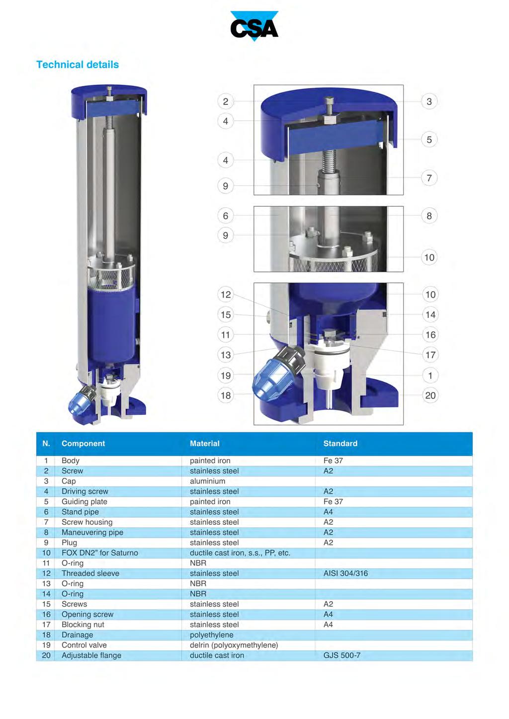
28 Water combination air valve underground version Mod. Saturno The Saturno air valve has been designed to provide the proper solution for underground installations, without the need of any sectioning devices to be installed on the pipe, when for cost savings or simply for practical reasons digging and chambers are not possible. The air valve will ensure the proper operation of the pipeline networks allowing the release of air pockets during working conditions, the evacuation and the entrance of large volumes of air during filling and draining operations. Technical features and benefits A new and reliable solution compared to the conventional way of installing air valves, requiring deep excavation to house concrete structures and whatever necessary to create the proper pit like TE piece, sectioning devices, the air valves itself and more. Saturno's innovative concept is based on the possibility of installing it directly on the TE piece before filling up the trench without any sectioning device, therefore dramatically reducing the overall cost. A simple manhole on the ground ( DN 300 is recoended) is sufficient to carry out proper maintenance. Standpipe in firmly secured to the basement to protect the air valves inside of it, and to hold the upper guide connected to the maneuvering system. Flanged basement to hold the check valve and the exhaust pipe 3/8" to avoid the accumulation of water into the standpipe. The combination air valve FOX housed into the flanged basement where its movement is controlled by a shaft, connected to its cover and whose water tightness is ensured by two o-rings. The system allows for proper maintenance simply by sectioning the flow rotating the maneuvering screw from the top, and extracting it from above. Applications Water distribution networks. Pressurized system with treated water.


29 Operating principle. Discharge of large volumes of air During the pipe filling it is necessary to discharge air as water flows in. The FOX 3F, thanks to an aerodynamic full port body and deflector, will make sure to avoid premature closures of the mobile bloc k during this phase. 2. Air release during working conditions During operation the air produced by the pipeline is accumulated in the upper part of the air valve. Little by little it is compressed and the pressure arrives to water pressure, therefore its volume increases pushing the water level downwards allowing the air release through the nozzle Entrance of large volumes of air During pipeline draining, or pipe bursts, it is necessary to bring in as much air as the quantity of outflowing water to avoid negative pressure and serious damages of the pipeline, and to the entire system. Installation The installation of Saturno simply requires a derivation from the main pipe, a manhole on top to allow for maintenance operations. The picture depicts the proper installation where the drain port plays a fundamental role, allowing for the water discharge from the main pipe. Normally supplied with 3/8 connection it should be positioned within a layer of small stones to facilitate the draining. Air valve removal The design of the underground air valve Saturno allows for a maintenance and replacement without removing the air valve from the pipe, simply acting on the cap and maneuvering key from above as shown on the picture on the right. All the components will be pulled out from the top without the need of digging and further operations.
30 Air flow performance charts AIR DISCHARGE DURING PIPE FILLING BAR,,4,4,3,3,2,2,,, m 3 /h 0,9 0,9 0,8 0,8 0,7 0,7 0,6 0,6 0, BAR 0, AIR ENTRANCE DURING PIPE DRAINING Working conditions Treated water 60 C max.. Maximum pressure 6 bar. Minimum pressure 0,3 bar. Standard Designed in compliance with EN-74/4 and AWWA C-2. Flanges according to EN 92/2, ANSI. Epoxy painting applied through fluidized bed technology blue RAL 00. Changes and variations on the flanges and painting details available on request. bar O / O,2 / O, / O,8 / Q (nl/s) AIR RELEASE DURING WORKING CONDITIONS A DN A B C D Weight Kg , 22, 20, , 82, 22, 22, 23,2 2,3 B , 22, 28, , 22, , 22, 24,7 26, , 30, D C
31


32 Advanced testing facilities Designed to reproduce real conditions of modern water distribution systems the CSA testing facility is able to assess the dynamic performances of automatic control valves, direct acting pressure control valves, air valves and anti water haer valves. Provided with a high capacity booster pumps station, and linked to an advanced high frequency pressure transducers and flow meters, the testing rig allows for a real time visualization of pressure and flow evolutions. Water haer events can also be simulated and recorded to prove the efficacy of CSA fast acting relief valve, in addition to level control for which, using an auxiliary stilling tank, a part of the pipeline system is entirely dedicated. The PLC and control station allows for the operation of step by step and solenoid operated valves to determine the sensitivity of such kind of application and pressure management solutions. Thanks to this important and powerful tool valves can be customized, simulated and set according to the project requirements assuring the perfect performance and accuracy. The testing process All our valves undergo severe tests according to EN standards to ensure they are mechanically resistant, watertight, and high performing. After testing every valve is identified by means of a metallic tag or sticker, and duly registered and certified. 30


33 Water haer analysis CSA Hyconsult CSA Hyconsult was founded to provide designers and consultants, involved in the design of water distribution and sewage systems, with accurate and unique technical support. CSA Hyconsult has specialized in hydraulic modelling and transients analysis, entirely through the use of modern computational tools and advanced algorithms. Simulations are essential to predict system responses to events under a wide range of conditions without disrupting the actual system. Using simulations, problems can be anticipated in possible or existing situations, and solutions can be evaluated in order to invest time, money and material in the most productive manner. Research and innovation CSA has always regarded knowledge as being indispensable for the kind of research that consistently feeds innovation at all levels. The R&D department at CSA constantly strives to improve product performance and continually searches for new solutions to meet our customer's needs. Twenty years of experience in valve design and sizing, supported by advanced computational tools, cooperation with external entities at the highest level, and test facilities for the verification of theoretical results which are available for our customers, guarantee our professionalism and reliability. 3
 -")
34 CSA s.r.l. - Strada San Giuseppe, - località Ponteghiara Salsomaggiore Terme (PR) - Italy TEL FAX info@csasrl.it
Wastewater combination air valve in stainless steel AISI 316 Mod. SCS
 Wastewater combination air valve in Mod. SCS The air valve guarantees the proper operation of sewage/industrial lines allowing the entrance of large quantity of air in case of pipe bursting or draining,
BERMAD Waterworks. Combination Air Valve. Air Valves Series. Typical Applications. Features & Benefits. Additional Features.
 BERMA Waterworks Combination Air Valve Model C7 BERMA C7 is a high quality combination air valve for a variety of water networks and operating conditions. It evacuates air during pipeline filling, allows
Working with air valves
 Working with air valves The company was founded in 1987 by transforming the former CSA, which was a trading company dealing with pipes and valves for water networks, into a manufacturing company, through
Flanged pressure reducer/stabilizer VRCD
 Flanged pressure reducer/stabilizer VRCD 2 This unit reduces and stabilizes the upstream pressure by operating on its load losses with a constant downstream pressure irrespective of the rate of flow value.
Serie ECO 3F. Flanged back flow preventer with controllable reduced pressure zone. made in. Application fields. Protection
 Flanged back flow preventer with controllable reduced pressure zone made in Application fields WATER FIRE FIGHTING DRINKING WATER 64 www.brandoni.it The ECO 3F flanged backflow preventers, which have a
BERMAD Waterworks. Level Control Valve with Altitude Pilot. 700 Series. Model X. Features and Benefits. Major Additional Features
 Level Control Valve with Altitude Pilot High level reservoirs & water towers Energy cost critical systems Systems with poor water quality Inherent refreshing Level sustaining at reservoir outlet The Level
DAV - MP DAV - MP. Metallic-Shield Air Valves. Product Catalogue. (Metallic-Shield Air Valves) DAV - MP
 DAV - MP") DAV - MP Metallic-Shield Air Valves Product Catalogue DAV - MP DAV - MP (Metallic-Shield Air Valves) Edition 9/ DAV Series DAV-MP Overview General The presence of trapped air in a pressurized pipeline
DAV - MP Metallic-Shield Air Valves Product Catalogue DAV - MP DAV - MP (Metallic-Shield Air Valves) Edition 9/ DAV Series DAV-MP Overview General The presence of trapped air in a pressurized pipeline
Serie ECO 3T. Threaded end back flow preventer with controllable reduced pressure zone. made in. Application fields. Protection E U R O P E
 Serie ECO T Threaded end back flow preventer with controllable reduced pressure zone BRANDONI made in E U R O P E Application fields WATER FIRE FIGHTING DRINKING WATER 74 www.brandoni.it Serie ECO T The
Combination Air Valve
 Combination Air Valve For Sewage and Wastewater Model C50 Installation, Operation and Maintenance Manual (IOM) Table of Contents General... Page 2 Safety... Page 2 Operational Data... Page 3 Materials
DAV - P. Product Catalogue DAV - P. Air release & Vacuum Break Valves. (Plastic Air Valves) DAV - P. Edition 2012
 DAV - P. Edition 2012") Product Catalogue DAV - P DAV - P Air release & Vacuum Break Valves Edition 1 DAV - P (Plastic Air Valves) DAV Series Overview General The presence of trapped air in a pressurized pipeline can have serious
Product Catalogue DAV - P DAV - P Air release & Vacuum Break Valves Edition 1 DAV - P (Plastic Air Valves) DAV Series Overview General The presence of trapped air in a pressurized pipeline can have serious
AIR RELIEF VALVES NETWORK PROTECTION
 AIR RELIEF VALVES NETWORK PROTECTION AIR RELIEF VALVES NETWORK PROTECTION Problems caused by the presence of air in networks may be solved by fitting suitable equipment. BELGICAST can supply a wide range
DAV Series. DAV-MH Air Release & Vacuum Break Valves
 DAV-MH Air Release & Vacuum Break Valves ISO 9 AVFI Pty Ltd 4 Enterprise Drive Bundoora Vic 383 p: 3 8467 f: 3 8467 99 e: avfi@avfi.com.au w: www.avfi.com.au General DAV-MH Air Release and Vacuum Break
NEW TYPE M PRESSURE RELIEF DEVICE
 NEW TYPE M PRESSURE RELIEF DEVICE M PRESSURE RELIEF DEVICE ACCORDING TO EN 50216-5/A2 PATENTED 2 PRESSURE RELIEF DEVICE TYPE 50 M Section A-A 170 139 Transformer tank F 41.5 3 ø48.3 ø166 A P.R.D. TAG A
DAV - WP DAV - WP. Wastewater Air Valves. Product Catalogue. (Wastewater Air Valves) DAV - WP
 DAV - WP") DAV - WP Wastewater Air Valves DAV - WP (Wastewater Air Valves) Product Catalogue DAV - WP DAV Series??? DAV-WP General DAV-WP Wastewater Air Valves The DAV-WP valve has been designed for efficient discharge
DAV - WP Wastewater Air Valves DAV - WP (Wastewater Air Valves) Product Catalogue DAV - WP DAV Series??? DAV-WP General DAV-WP Wastewater Air Valves The DAV-WP valve has been designed for efficient discharge
Size : Connection Ends : Min Temperature : Max Temperature : Materials : Cast iron body
 Size : Connection Ends : Min Temperature : Max Temperature : DN 50 to 200 Flanged ISO PN 10/16 ( ISO PN16 for DN200 ) 0 C + 50 C Max Pressure : 16 Bars Specifications : Tangential type Dry dial Magnetic
Combination Air Valve Model
 Combination Air Valve Model Model C10 /C11 Installation, Operation and Maintenance Manual (IOM) Table of Contents General...Page 2 Safety...Page 2 Operational Data...Page 3 Materials and Connections...Page
Description. Functions. Technical data. Applications. Tests. On-Off 2 levels float control valve, closing at high level and opening at low level.
 DN 0 to 1000 - Serie K3 0 On-Off levels float control valve, closing at high level and opening at low level. Functions Prevents overflowing and closes at a constant and adjustable high level. Remains closed
Ball valve HKSF-W100. Ball valve HKSF-W100. RMA Kehl GmbH & Co. KG Oststrasse 17 D Kehl / Germany
 Ball valve HKSF-W100 RMA Kehl GmbH & Co. KG Oststrasse 17 D-77694 Kehl / Germany info@rma-kehl.de www.rma-armaturen.de 1 Design Features: RMA-ball valves type HKSF-W are fully welded and completely maintenance-free
Installation and operation Manual. Bermad Surge Anticipation Valve. Model No 435
 Instruction manual Bermad surge anticipation manual Model No 435 Installation and operation Manual Bermad Surge Anticipation Valve Model No 435 Bermad Water Technologies Rev 0 5/05/2015 7 Inglewood Drive,
SAN ANTONIO WATER SYSTEM I.H. 10 Ground Storage Tank Rehabilitation and Painting Project SAWS Job No Solicitation No.
 SAN ANTONIO WATER SYSTEM I.H. 10 Ground Storage Tank Rehabilitation and Painting Project SAWS Job No. 13-0118 Solicitation No. B-16-014-GC September 1, 2016 TO BIDDER OF RECORD: The following changes,
Product Catalogue DAV - P DAV - P. Air release & Vacuum Break Valves. (Plastic Air Valves) DAV - P
 DAV - P") Product Catalogue DAV - P DAV - P Air release & Vacuum Break Valves DAV - P (Plastic Air Valves) DAV Series??? Overview General The presence of trapped air in a pressurized pipeline can have serious effects
Product Catalogue DAV - P DAV - P Air release & Vacuum Break Valves DAV - P (Plastic Air Valves) DAV Series??? Overview General The presence of trapped air in a pressurized pipeline can have serious effects
INSTALLATION, OPERATION AND MAINTENANCE HANDBOOK
 INSTALLATION, OPERATION AND MAINTENANCE HANDBOOK XLC 430 FLOW CONTROL VALVE INSTALLATION, OPERATION AND MAINTENANCE HANDBOOK Model XLC 430 This handbook provides information about the installation, operation
CAST IRON SAFETY VALVE TYPE 6301
 CHARACTERISTICS The 6301 safety valve is dedicated to protect the equipment from potential overpressure. This is an automatic device that closes when the pressure conditions are back to normal. It is a
Size : Ends : Min Temperature : Max Temperature : Materials : Cast iron body
 Size : Ends : Min Temperature : Max Temperature : DN 40 to DN 300 Flanges R.F. PN10/16-10 C + 80 C Max Pressure : 16 Bars up to DN200 Specifications : Removable stainless steel filter Bolted bonnet with
Water. VAG DUOJET Automatic Air Valve Single-chamber type PN 10/16/25/40 - DN KAT-A 1912
 Water VAG DUOJET Automatic Air Valve Single-chamber type Product characteristics and benefits Resilient seated With flange end acc. to EN 1092-2 Single chamber air valve in compact design Very high discharge
Air Valves Head Office : İşçiler Caddesi No: 124 Yenişehir / İZMİR-TURKEY Phone: (pbx)
") Air Valves Head Office : İşçiler Caddesi No: 124 Yenişehir / İZMİRTURKEY Phone: 0232 457 57 08 (pbx) Fax: 0232 4 23 50 Branch : 1203/4 Sokak No: 1/C Yenişehir / İZMİRTURKEY Phone: 0232 44 31 30 Factory
Air Valves Head Office : İşçiler Caddesi No: 124 Yenişehir / İZMİRTURKEY Phone: 0232 457 57 08 (pbx) Fax: 0232 4 23 50 Branch : 1203/4 Sokak No: 1/C Yenişehir / İZMİRTURKEY Phone: 0232 44 31 30 Factory
756 Safety Relief Valves
 756 S a fe t y R e l i e f Va l ve s INTRODUCTION 756 Safety Relief Valves The effects of exceeding safe pressure levels in an unprotected pressure vessel or system, can have catastrophic effects on both
Pressure and Flow Control Valves DBGM, German and European Patents
 Pressure and Flow Control Valves DBGM, German and European Patents Absolutely Reliable Pressure and Flow Control In water mains of sizes DN 50 to DN 150, ERHARD Control Valves in straight or angle pattern
MITIGATING PIPE AND RISER HYDRAULIC PIPELINE ISSUES WITH THE I-RISER PLUS
 24 TH July 2013 MITIGATING PIPE AND RISER HYDRAULIC PIPELINE ISSUES WITH THE I-RISER PLUS Vern Costelow Business Development Consultant AWMA Water Control Solutions INTRODUCTION Surface irrigation is still
SUBMITTAL NOTES PROJECT: Ross Model 50RWR-A Pilot Operated Surge Relief Valve with Hydraulic Anticipation. Size: inch / mm
 SUBMITTAL NOTES PROJECT: Ross Model 50RWR-A Pilot Operated Surge Relief Valve with Hydraulic Anticipation Size: inch / mm Every Ross Valve shall be hydrostatically tested for body integrity and tight seating
VACUVENT VE SERIES CATALOGUE
 VACUVENT VE SERIES CATALOGUE October 2018 " ba f wa e " The Triple Function Air Valve Vacuvent offers a tri function air valve that not only breaks vacuum, but also reduces surge on pipeline filling and
Materials : Carbon steel ASTM A216 WCB
 Certificate 3.1 Size : Ends : Min Temperature : Max Temperature : DN 50 to DN 400 ( NPS 2" to 16" ) Flanges R.F. Class 150 (PN20) - 29 C + 425 C Max Pressure : 20 Bars Specifications : Removable stainless
A soft sealed atmospheric safety valve with large flow capacity and soft seat tightness for steam condenser and turbine applications
 SAPAG A soft sealed atmospheric safety valve with large flow capacity and soft seat tightness for steam condenser and turbine applications Features The Sapag Series 1100 steam safety valve is used for
Filling valves AL, ALM Series Automatic filling units ALOMDIW, ALOMDNW Series
 Filling valves AL, ALM Series Automatic filling units ALOMDIW, ALOMDNW Series Main features Designed for automatic filling of sealed heating systems and for protection of the water mains from risk of contamination.
700 SIGMA SERIES ENGINEERING DATA
 700 SIGMA SERIES ENGINEERING DATA CONTENT 700 SIGMA EN/ES 2-8 700 SIGMA EN/ES 2 Exploded View 3 Material Specifications 4 Principle of Operation 5 Plug Options 6 Cavitation 7 Cavitation Cage 8 700 SIGMA
BERMAD Fire Protection Hydraulic Control Valves
 BERMAD Fire Protection Hydraulic Control Valves Control Solutions with the Power to Protect BERMAD - The Company Since its foundation in 1965, BERMAD has focused its efforts on innovation, quality and
AIR AND VACUUM VALVES
 MINING DIVISION AIR AND VACUUM VALVES FOR HIGH FLOW K-6NS SERIES DESCRIPTION The K-6NS Series Air and Vacuum Valve discharges air during the filling or charging of the system and admits air into the system
E 328 E 498 Tank top mounting Connection up to G1½ / -24 SAE and SAE 2 Nominal flow rate up to 600 l/min / gpm
 Return-Suction Filters E 8 E 98 Tank top mounting Connection up to G½ / - SE and SE Nominal flow rate up to 6 l/min / 8. gpm Description pplication For operation in units with hydrostatic drives, when
776 Cryogenic Safety Valve
 776 Cryogenic Safety Valve INTRODUCTION 776 Cryogenic Safety Valve The effects of exceeding safe pressure levels in an unprotected pressure vessel or system, can have catastrophic effects on both plant
Materials : Stainless steel ASTM A351 CF8M
 Certificat 3.1 Size: Ends : Min Temperature : Max Temperature : DN 15 to DN 200 PN16 Flanges R.F. - 20 C + 200 C Max Pressure : 16 Bars Specifiations : Removable stainless steel filter Bolted bonnet with
Plumbing Products FLOOR DRAIN CLEANOUT GATE VALVE BALL VALVE.
 Plumbing Products FLOOR DRAIN CLEANOUT GATE VALVE BALL VALVE www.wilsontaylor.co INTRODUCTION Wilson Taylor Asia Pacific, headquartered in Singapore with a subsidiary based in Hong Kong and a representative
INDUSTRIAS IBAIONDO, HYDROPNEUMATIC TANKS
 IBAIONDO, HYDROPNEUMATIC TANKS IBAIONDO, INTRODUCTION Hydropneumatic tanks are designed to be used in potable water supply installations as a part of the pressure booster set in order to ensure the adequate
Consult with manufacturers concerning permeation of the pipe walls, jointing materials, valve seats, etc.
 Design Manual Chapter 4 - Water Mains 4C - Facility Design 4C-1 Facility Design A. General Water mains and appurtenances, including hydrants and valves, should be provided along all streets including connections
Size : Ends : Min Temperature : Max Temperature : Materials : Cast iron body
 Size : Ends : Min Temperature : Max Temperature : DN 15 to DN 400 Flanges GN10/16-10 C + 120 C Max Pressure : 16 Bars up to DN 200 ( 10 bars over ) Specifications : Removable stainless steel filter Bolted
300 Series. Automatic Hydraulic Control Valves
 Automatic Hydraulic Control Valves AVFI Pty Ltd 54 Enterprise Drive Bundoora Vic 3083 p: 03 8467 0000 f: 03 8467 0099 e: avfi@avfi.com.au w: www.avfi.com.au 300 Series General 300 SERIES Automatic Hydraulic
TECHNOLOGIES. M Series. Positive return metering pumps [API675]
![TECHNOLOGIES. M Series. Positive return metering pumps [API675]](/thumbs/90/101415964.jpg "TECHNOLOGIES. M Series. Positive return metering pumps [API675]") M Series Positive return metering pumps [API675] Hydraulic double diaphragm metering pump in AISI 316L stainless steel A line of plunger and hydraulic double diaphragm metering pumps designed according
M Series Positive return metering pumps [API675] Hydraulic double diaphragm metering pump in AISI 316L stainless steel A line of plunger and hydraulic double diaphragm metering pumps designed according
Slam Shut Valves SCN
 Slam Shut Valves SCN SCN > Slam shut valves Introduction SCN is a compact safety device (SAV) which quickly intercept gas flow whenever the pressure under monitoring reaches a pre-set limits, or whenever
IFS NUVENT SERIES IWF FOR POTABLE WATER ANTI SLAM AIR RELEASE AND VACUUM BREAK AIR VALVES
 IFS NUVENT SERIES IWF FOR POTABLE WATER ANTI SLAM AIR RELEASE AND VACUUM BREAK AIR VALVES CONTENTS About IFS High volume air discharge Curves and operation Anti slam air discharge Curves and operation
HEAVY DUTY KNIFE GATE VALVE
 HEAVY DUTY KNIFE GATE VALVE The (SER.22) model knife gate is a bi-directional lug type valve designed according to MSS-SP-81 and TAPPI TIS 405-8 for industrial service applications. The completely new
RAPHAEL is a company of AIR VALVES
 RAPHAEL is a company of AIR VALVES DESCRIPTION and TECHNICAL Air Valves General : What is an Air Valve? : An air valve is a valve mounted in TEE configuration on a pipeline to discharge or admit air into
Journal of Applied Fluid Transients, Vol 1-1, April 2014 (3-1)
") Modeling and Field Verification Study of Air Slam Conditions on kalanit Pipeline System By Yiftach Brunner & Sathish Kumar ir valves are integral part of long water transmission mains and are essential
Modeling and Field Verification Study of Air Slam Conditions on kalanit Pipeline System By Yiftach Brunner & Sathish Kumar ir valves are integral part of long water transmission mains and are essential
CSA waterworks line. Flow rate automatic control valve. Mod. XLC 430
 CSA waterworks line Flow rate automatic control valve Mod. XLC 0 Introduction This manual will provide you with the information to properly install and maintain CSA automatic control valves XLC 00 series.
Pressure reducing valves Index
 Index General information page Introduction 506 General introduction 507 for a steam plant 509 Product information BSP thread page Brass 510 ; BSP female thread 511 ; BSP male thread 513 Stainless steel
Dean Pump Self-Priming Chemical Process Pumps
 Bulletin C 1.2.34.7 Dean Pump Self-Priming Chemical Process Pumps php Series HEAD CAPACITY RANGE CHARTS php Self Primer - 2 Pole 3500 RPM 500 CAPACITY M 3 /HR 2900 RPM 50 HERTZ 25 50 75 125 150 400 TOTAL
E 084 Tank top mounting Connection up to G1 / -16 SAE Nominal flow rate up to 80 l/min / 21.1 gpm
 Return-Suction Filters E 08 Tank top mounting Connection up to G / -6 SE Nominal flow rate up to 80 l/min /. gpm Description pplication For operation in units with hydrostatic drives, when the return flow
FITTINGS AND VALVES Düker Plunger Valve RKV Type 7015 Professional control of flow rates, reservoir levels and pressures Safe, hygienic and durable!
 FITTINGS AND VALVES Düker Plunger Valve RKV Type 7015 Professional control of flow rates, reservoir levels and pressures Safe, hygienic and durable! 1 The New Düker Plunger Valve Type 7015 St Plunger valves
Air Eliminators and Combination Air Eliminators Strainers
 Description Air Eliminators and Combination Air Eliminator Strainers are designed to provide separation, elimination and prevention of air in piping systems for a variety of installations and conditions.
Installation, operation & maintenance manual - original version
 Installation, operation & maintenance manual - original version AVK gate valves for water and wastewater Series 01, 02, 06, 12, 15, 18, 20, 26, 32, 33, 36, 38, 50, 55 and 636 COPYRIGHT AVK GROUP A/S 2018
CA10S, CA14 and CA14S Air and Gas Traps
 1448150/9 IM-P148-13 ST Issue 9 CA10S, CA14 and CA14S Air and Gas Traps Installation and Maintenance Instructions 1. Safety information 2. General product information 3. Installation 4. Commissioning 5.
USER MANUAL. 1. Principle of operation. 2. Delivery condition. SPRING-LOADED SAFETY VALVES zarmak. Edition: 07/2016 Date: V (ex.
 ZETKAMA Sp. z o.o. ul. 3 Maja 12 PL 57-410 Ścinawka Średnia SPRING-LOADED SAFETY VALVES zarmak USER MANUAL 782V (ex. 782) Edition: 07/2016 Date: 01.07.2016 TABLE OF CONTENTS 1. Principle of operation 2.
PRODUCTS CATALOGUE 2017 / Torino - Strada Settimo 388/15 Tel (+39) /43 Fax (+39)
 /43 Fax (+39)") PRODUCTS CATALOGUE 2017 / 2018 10156 Torino - Strada Settimo 388/15 Tel (+39) 011.223.68.42 /43 Fax (+39) 011.223.67.67 info@ebarbero.com www.ebarbero.com CATALOGO INDEX PRODOTTI 2017 / 2018 Pumps for
PRODUCTS CATALOGUE 2017 / 2018 10156 Torino - Strada Settimo 388/15 Tel (+39) 011.223.68.42 /43 Fax (+39) 011.223.67.67 info@ebarbero.com www.ebarbero.com CATALOGO INDEX PRODOTTI 2017 / 2018 Pumps for
ANNEX AMENDMENTS TO THE INTERNATIONAL CODE FOR FIRE SAFETY SYSTEMS (FSS CODE) CHAPTER 15 INERT GAS SYSTEMS
 CHAPTER 15 INERT GAS SYSTEMS") Annex 3, page 2 ANNEX AMENDMENTS TO THE INTERNATIONAL CODE FOR FIRE SAFETY SYSTEMS (FSS CODE) CHAPTER 15 INERT GAS SYSTEMS The text of existing chapter 15 is replaced by the following: "1 Application This
Annex 3, page 2 ANNEX AMENDMENTS TO THE INTERNATIONAL CODE FOR FIRE SAFETY SYSTEMS (FSS CODE) CHAPTER 15 INERT GAS SYSTEMS The text of existing chapter 15 is replaced by the following: "1 Application This
E 328 E 498 Tank top mounting Connection up to G1½ and SAE 2 Nominal flow rate up to 600 l/min
 Return-Suction Filters E 8 E 98 Tank top mounting Connection up to G½ and SE Nominal flow rate up to 6 l/min Description pplication For operation in units with hydrostatic drives, when the return flow
WATER METERS.
 WATER METERS Can be installed Pulse output with both plug & play system horizontal and vertical No straight Higher sections accuracy required U0 D0 Water engineering High resistance Its operation is based
SYSTEM REGULATING VALVES PRESSURE RELIEF VALVE - SRV BRASS & S/STEEL ADJUSTABLE
 SYSTEM REGULATING VALVES PRESSURE RELIEF VALVE - SRV BRASS & S/STEEL ADJUSTABLE This piston style pressure relief valve with conical shaped needle seat for accurate adjustment is available up to 3 in size.
TECHNICAL DATA. Q = C v P S
 Page 1 of 13 1. DESCRIPTION The Viking 6 Model G-6000 Dry Valve Riser Assembly consists of a small profile, light weight, pilot operated valve that is used to separate the water supply from the dry sprinkler
Ø248 Ø Series. R 2.00 R 2 Hydraulic Control Valves R 3 R 6 SEE "SEAT DE T DETAIL NO. 2" CONTROL VALVES
 Ø290 Ø248 Ø240 RAM Ø201 400 Series R 2.00 R 2 Hydraulic Control Valves R 3 G 50 92 30 R 6 SEE "SEAT DE T DETAIL NO. 2" Ø290 Ø248 Ø240 Ø201 30 i n d e x How To Order R 2.00 R 2 2 Company profile 4 Hydraulic
Telefon (+45) Telefax (+45)
 Telefax (+45)") Uni-Valve A /S VENTILER & INSTRUMENTER Telefon (+45) 43 43 82 00 Telefax (+45) 43 43 74 75 mail@uni-valve.com www.uni-valve.com UNI-S83 / S84 3/4-way ball valve Installation and Operating manual 3/4-WAY
Uni-Valve A /S VENTILER & INSTRUMENTER Telefon (+45) 43 43 82 00 Telefax (+45) 43 43 74 75 mail@uni-valve.com www.uni-valve.com UNI-S83 / S84 3/4-way ball valve Installation and Operating manual 3/4-WAY
Pressure Regulating Valves. Models 44, 77 & 68 PS\ UL. Pressure Relief Valve. Dorot Fire Protection Division. Certification & compliance by design
 Fire Protection Div. Dorot Fire Protection Division Models, & 6 PS\ UL Pressure Relief Valve Certification & compliance by design -PS\UL ANSI FCI - Class VI seat leakage class Fire tested to EN ISO 6-:6
CSA waterworks line. Direct acting downstream pressure reducer-stabilizer in stainless steel. Mod. VRCD-FF
 CSA waterworks line Direct acting downstream pressure reducer-stabilizer in stainless steel Mod. VRCD-FF 1 Introduction This manual will provide you with the information to properly install and maintain
ROTATING DISK VALVES INSTALLATION AND MAINTENANCE 1. SCOPE 3 2. INFORMATION ON USAGE 3 3. VALVE TYPES 3 4. OPERATORS 5 5. VALVE CONSTRUCTION 6
 Sub Section INDEX Page Number 1. SCOPE 3 2. INFORMATION ON USAGE 3 3. VALVE TYPES 3 4. OPERATORS 5 5. VALVE CONSTRUCTION 6 6. INSTALLATION AND OPERATION 6 7. MAINTENANCE 8 8. REPAIR 9 9. ASSEMBLY 10 10.
S300 Series. Valve Link. Features. Fisher Controls
 S0 Series Self-Operated Type VL FIELDVUE Regulators Valve Link Fisher Controls May 198 Bulletin 71.1:S0 The S0 Series self-operated, spring-loaded regulators are used for pressure-reducing control in a
Series RGX "ANTI - SURGE" AIR RELEASE & VACUUM BREAK VALVES CATALOGUE INDEX PAGE
 CONTENT Series RGX "ANTI - SURGE" AIR RELEASE & VACUUM BREAK VALVES CATALOGUE INDEX PAGE OPERATION -SERIES RGX 1-2 RECOMMENDED INSTALLATION ARRANGEMENTS -SERIES RGX 3 AVAILABLE DISCHARGE CONNECTIONS -SERIES
Solenoid valves, two-step on/off Type PMLX REFRIGERATION AND AIR CONDITIONING. Technical leaflet
 Solenoid valves, two-step on/off PMLX REFRIGERATION AND AIR CONDITIONING Technical leaflet Contents Page Introduction........................................................................................3
Homestead Series 820 AWWA Butterfly Valves
 Homestead Series 820 AWWA Butterfly Valves Dependable Valves for Water & Wastewater Service BODY: The ductile iron body meets or exceeds the design strength requirements of the AWWA C504 standards. Flange
627 Series Pressure Reducing Regulators
 627 Series Pressure Reducing Regulators Introduction The 627 Series direct-operated pressure reducing regulators (Figure 1) are for low and high-pressure systems. These regulators can be used with natural
CSO/STORMWATER MANAGEMENT. HYDROVEX FluidMoon Self-Adjusting Knife-Gate Regulator
 CSO/STORMWATER MANAGEMENT HYDROVEX FluidMoon Self-Adjusting Knife-Gate Regulator HYDROVEX FLUIDMOON SELF-ADJUSTING KNIFE-GATE REGULATOR APPLICATION The Hydrovex FluidMoon Self-Adjusting Knife-Gate Regulator
Self-operated Pressure Regulators Type 2405 Pressure Reducing Valve
 Self-operated Pressure Regulators Type 2405 Pressure Reducing Valve ANSI version Application Pressure reducing valve for set points from 0.075 to 150 psi (5 mbar to 10 bar) Valve size NPS ½ to 2 1) (DN
Self-operated Pressure Regulators Type 2405 Pressure Reducing Valve
 Self-operated Pressure Regulators Type 2405 Pressure Reducing Valve Application Pressure reducing valve for set points from 5 mbar to 10 bar Nominal size DN 15 to 50 Nominal pressure PN 16 to 40 Suitable
TEST SPECIFICATION NYT-909-C
 748 Starbuck Ave, Watertown, NY 13601 Phone: +1-315-786-5200 Engineering Fax: +1-315-786-5673 TEST SPECIFICATION NYT-909-C CODE OF TESTS FOR TESTING "AB" TEST RACK P/N 702546 & 702612 ISSUE NO. 5 1.0 THE
RMG 5020 Gas Pressure Regulator Enabling Dependable Gas Operations
 RMG 5020 Gas Pressure Regulator Enabling Dependable Gas Operations Proven Technology. Superior Performance. Today s natural gas industry has a growing demand for operational excellence. Pilot-operated
SCA Series Inverted Bucket Steam Traps
 0770050/5 IM-P077-06 ST Issue 5 SCA Series Inverted Bucket Steam Traps Installation and Maintenance Instructions 1. General safety information 2. General product information 3. Installation 4. Commissioning
INSTRUCTION MANUAL Pressure Relief Device LPT
 INSTRUCTION MANUAL Pressure Relief Device LPT 5COV475800 LPT REV00 CONTENT: 1 SAFETY 1.1 Safety instructions 2 1.2 Specified applications 2 1.3 Safety notes on the equipment operation 2 2 PRESSURE RELIEF
High Performance BSP Dial Up Pattern Pressure Reducing Valve
 See our full range online at: www.vip-ltd.co.uk High Performance BSP Dial Up Pattern Pressure Reducing Valve VIP Product Code 31/0103 FUNCTION Pressure reducing valves are devices which, when installed
E 158 E 198 E 248. Tank top mounting Connection up to G11 / 4 Nominal flow rate up to 250 l/min e d
 R e t u r n - S u c t i o n F i l t e rs E 158 E 198 E 248 Tank top mounting Connection up to G11 / 4 Nominal flow rate up to 250 l/min 20.90-5e 0.0-2d D e s c r i p t i o n Application For operation in
Normal Safety Valves with spring loading. (AN) Model 295 and 296
 Model 295 and 296") GB-1 EN Model 295 Model 296 Thread connection Flange connection The valve works as an automatic pressure releasing regulator activated by the static pressure existing at the entrance to the valve and is
GB-1 EN Model 295 Model 296 Thread connection Flange connection The valve works as an automatic pressure releasing regulator activated by the static pressure existing at the entrance to the valve and is
DN 1/2" to 2" Female BSP + 0 C C Max Pressure : 16 Bars Specifications : Stainless steel removable filter Female / Female With draining valve
 Size : Ends : Min Temperature : Max Temperature : DN 1/2" to 2" Female BSP + 0 C + 120 C Max Pressure : 16 Bars Specifications : Stainless steel removable filter Female / Female With draining valve Materials
Auxiliary valve QDS6 Sequence valve, 3-way. Catalogue (GB) (US) October 1998
 (US) October 1998") Auxiliary valve Sequence valve, 3-way Catalogue 9129 8542-02 (GB) 9129 8542-06 (US) October 1998 Sequence valve, 3-way Applications The sequence valve is designed to open or close a hydraulic pilot signal
Auxiliary valve Sequence valve, 3-way Catalogue 9129 8542-02 (GB) 9129 8542-06 (US) October 1998 Sequence valve, 3-way Applications The sequence valve is designed to open or close a hydraulic pilot signal
Ref GAS WAFER BUTTERFLY VALVE. Model/Ref:
 Model/Ref: 1141 www.lauridsenindustri.com Size : Ends : Min Temperature : Max Temperature : DN 32/40 to 200 mm Between ISO PN10/16 and ANSI150 flanges - 20 C + 60 C Max Pressure : 5 Bars Specifications
PRESSURE REDUCING VALVE EUROBRASS 143 FF
 Scheda prodotto Eurobrass 143 ENG Rev. 5 09/2012 PRESSURE REDUCING VALVE EUROBRASS 143 FF Direct acting brass pressure reducing valve; PN 25; Adjustable outlet pressure between 0,5 and 6 bar; Brass diaphragm
1805 Series Relief Valves
 Instruction Manual Form 1211 1805 Series October 2011 1805 Series Relief Valves! WARNING Failure to follow these instructions or to properly install and maintain this equipment could result in an explosion
POP Safety Valve. POP Safety Valve INTRODUCTION DEFINITIONS
 POP Safety Valve POP Safety Valve INTRODUCTION The effects of exceeding safe pressure levels in an unprotected pressure vessel or system, can have catastrophic effects on both plant and personnel. Safety
Guideline No.M-05(201510) M-05 AIR COMPRESSOR. Issued date: 20 October China Classification Society
 M-05 AIR COMPRESSOR. Issued date: 20 October China Classification Society") Guideline No.M-05(201510) M-05 AIR COMPRESSOR Issued date: 20 October 2015 China Classification Society Foreword This Guideline constitutes the CCS rules, and establishes the applicable technical requirements
Guideline No.M-05(201510) M-05 AIR COMPRESSOR Issued date: 20 October 2015 China Classification Society Foreword This Guideline constitutes the CCS rules, and establishes the applicable technical requirements
i n f b e r m a d. c o m w w w. b e r m a d. c o m
 asic Valve IR-900-M ydrometer with Magnetic Drive The ERMAD Model IR-900-M is a unique product integrating both a vertical turbine oltman-type water meter and a diaphragm actuated hydraulic control valve.
T 2523 EN Type 2406 Excess Pressure Valve Self-operated Pressure Regulators ANSI version
 T 2523 EN Type 2406 Excess Pressure Valve Self-operated Pressure Regulators ANSI version Application Excess pressure valve for set points from 0.075 to 150 psi (5 mbar to 10 bar) Valve size NPS ½ to 2
Dual position solenoid valve Type ICSH 25-80
 Data sheet Dual position solenoid valve Type ICSH 25-80 ICSH dual position solenoid valve belongs to the ICV family and consists of an ICV housing, an ICS insert together with an ICSH top cover with 2
BERMAD Waterworks. Pressure Reducing Valve. 700 Series. Model 720. Features and Benefits. Major Additional Features
 Pressure Reducing Valve Flow and leakage reduction Cavitation damage protection Throttling noise reduction Burst protection System maintenance savings The Pressure Reducing Valve is a hydraulically operated,
Section GATE VALVES
 Section 02521 PART 1 GENERAL 1.01 SUMMARY This Section includes the furnishing and installation of gate valves for isolation and dead-end service as shown on Plans and as specified herein. 1.02 MEASUREMENT
Fig 1, Fig 12, Fig 13, Fig 14HP, Fig 16, Fig 16HP and Fig 16L Strainers
 16355/8 IM-S6-17 ST Issue 8 Fig 1, Fig 12, Fig 13, Fig 14HP, Fig 16, Fig 16HP and Fig 16L Strainers Installation and Maintenance Instructions 1. Safety information 2. General product information 3. Installation
MUELLER A A Non-Adjustable. Vertical Indicator Posts. Reliable Connections. General Information 2. Technical Data 3.
 Installation Instructions manual MUELLER table of contents PAGE A-20808 General Information 2 Technical Data 3 Dimensions 4 A-20809 Non-Adjustable Installation 5-6 Parts 7 Maintenance 8 Vertical Indicator