INDUSTRIAS IBAIONDO, HYDROPNEUMATIC TANKS
|
|
|
- Ariel Quinn
- 6 years ago
- Views:
Transcription


1 IBAIONDO, HYDROPNEUMATIC TANKS
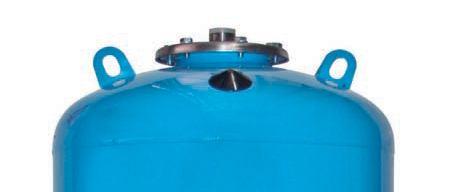
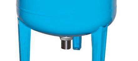
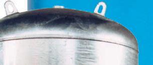
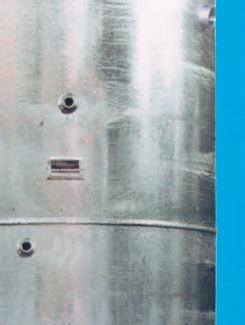
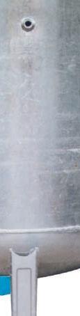
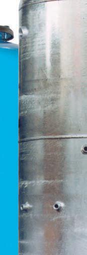
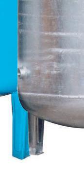
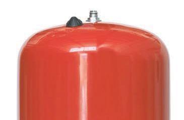
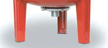
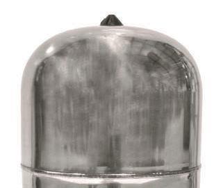
2 IBAIONDO, INTRODUCTION Hydropneumatic tanks are designed to be used in potable water supply installations as a part of the pressure booster set in order to ensure the adequate water supplies to buildings, houses, etc. Apart from keeping a pressurized water stock, the hydropneumatic tanks allow a longer life of the pumping unit due to the reduction of the starting and stopping operations involving a significant energy saving. Hydropneumatic tanks are manufactured by Industrias Ibaiondo, S.A, according to the safety standards of the European 97/23/EC Directive required for pressure units, guaranteeing the use of high quality materials and the proven experience of a highly skilled staff. The most important technical features of the hydropneumatic tanks and any other information related to manufacturing is shown on the identification label attached to the product. This label must not be changed or removed in any case. Every tank is also supplied with the operating instructions manual and the EC conformity certificate. DESCRIPTION Steel tanks manufactured according to the European 97/23/EC Directive regulations for pressure units. They are made with two embedded roots and a curved metal plate joined together by welding flanges and suitable to withstand loosely design working pressure. The tightness and resistance of the tanks are tested at 1.5 times higher than the maximum working pressure. The hydropneumatic tanks have inside a synthetic rubber bladder manufactured according to the physicalchemical features and to the legal requirements for sanitary water gathered in the DIN 4807 Norm. Bladders isolate permanently water from air/ nitrogen and they are designed to be almost entirely filled with water and to fit the shape of the tanks (maximum volumetric expansion), so that they ensure minimum elongation and prevent the material wear. This differential factor along with the thickness and composition of the manufacturing material guarantee the minimum loss of the tank precharge pressure. The threaded (DIN-259) or flanged (En 1,092-1) water connections are properly protected from corrosion. The bladder water tanks are provided with a valve for the pressure regulation of the air/nitrogen chamber. The outer coating consists of a minimum of 40 microns thick oven cured paint applied on the phosphated steel.

, the pressure switch, cuts power and the flow of water between the pump and the tank is stopped at this time.")
.")
3 IBAIONDO, OPERATION The drinking water collected directly from the water system, also from the pressure tanks series AMR-DUO, DG or DX is driven to the storage water tank by the pumping set. As the water enters the hydropneumatic tank, it is stored inside the bladder which separates tightly the water chamber from air/nitrogen chamber. This water inflow, causes a reduction of the initial volume of the enclosed air/ nitrogen in the tank which involves a pressure increase. When desired maximum pressure has been reached (stop pressure of the pump), the pressure switch, cuts power and the flow of water between the pump and the tank is stopped at this time. The stored energy of the enclosed air/ nitrogen inside the tank will lead the water inside the membrane to the consumption sites according to user needs. As the water flows and the bladder empties, the air/nitrogen pressure decreases till reaching the minimum set pressure (starting pressure of the pump). At that moment, the water feed flows again from the pumping set to the hydropneumatic tank. This cycle runs automatically as long as the minimum and maximum pressures are reached.


4 IBAIONDO, HYDROPNEUMATIC TANK VOLUME CALCULATION In order to obtain the volume of the hydropneumatic tank, it is necessary to know the following parameters: Q: Average flow of the pump in liters / minute. Zmax: Maximum pump-starting frequency allowed per hour. Pp: Pump stop pressure (Absolute) Pa: Pump start pressure (Absolute) Pc: Precharge pressure (Absolute) It is suggested Pc=Pa The volume of the tank will be calculated according to: HYDROPNEUMATIC TANK USEFUL VOLUME CALCULATION start pump pressure can be calculated as follows: Example: We have an overpressure installation equipped with a 300 lts/min flow pump (5 lts/sec) and pressure switches working with the following values: Pump starting pressure Pa = 3 Bar Pump stopping pressure Pp = 6 Bar Maximum pump - starting frequency allowed per hour Zmax = 12 The useful water volume: SELECTION CHART OF HYDROPNEUMATIC TANK DEPENDING ON USEFUL WATER VOLUME Switch minimum prressure Bar Capacity Switch minimum prressure Bar NOTE: In order to calculate pressure tanks without bladder or water hammer arrestors consult factory.

5 IBAIONDO, INSTALLATION & ASSEMBLY Before proceeding to the assembly, it is necessary to ensure that the volume of the hydropneumatic tank has been correctly calculated by the authorized technical staff, taking into account the booster set features. Hydropneumatic tank must be mounted by a professional installer bearing in mind the instructions provided with the product and the label. Hydropneumatic tank needs to be installed in a weather protected place which disposes of the necessary access dimensions in order to facilitate tank inspection. Air valve, connection sleeve and label must be easy to check. In the case of hydropneumatic tanks without feet or bracket, fastening system will be designed to be able to hold the tank weight completely full of water. Safety valve and manometer must be compulsorily installed. Safety valve will be calibrated according to the maximum system pressure and never higher to the maximum allowable pressure of the tank. Hydropneumatic tanks, depending on the model selected, will be connected straight to the pipe line at the lower side of the pump or directly on the pipe line at the pump impulsion.
6 IBAIONDO, COMMISSIONING Hydropneumatic bladder tanks are supplied from the factory with a pre-charge pressure indicated on the label added on product. However, in order to guarantee the right performance of the system, this value must be adjusted taking into account the characteristics of the installation: In the case of hydropneumatic tanks placed at the impulsion (High side) of the booster system, pre-charge value will be as follows: Pre-charge (Bar) = Pump start pressure 0,2 Bar In the case of the hydropneumatic tanks placed at the aspiration (Lower side) of the booster system, pre-charge value will be as follows: Pre-charge (Bar) = Pump start pressure 0,3 Bar If the pre-charge value is higher than the precharge pressure to which it has been supplied from the factory, previously to the air recharging operation, it will be necessary to introduce water through the inlet/outlet connection of the tank until cover the bottom coupling. Not to proceed in this way, could result in damage to the membrane as consequence of its extrusion. Once first step is done, we will isolate the hydropneumatic tank of the driving through closing the valve provided for this purpose. From this moment, air recharging will be made through the inflating valve of the tank, until pre-charge pressure is reached. Once pressure is adjusted, tank will be connected to the installation. Once the tank is connected, it works automatically MAINTENANCE Maintenance must be carried out exclusively by authorized staff. At least once a year, pre-charge pressure of the air/nitrogen side needs to be checked to confirm that it is between the right values indicated in previous points. Temperature contrasts should be similar. For that, it will be necessary to close the valve which communicates the tank with the installation and then empty the water of the tank. In case of the pre-charge and measured pressure varies around 20%, it needs to be adjust to the original value, pre-charge pressure, following the instructions pointed in previous points. DISASSEMBLY In no case the tank will be disassembly without depressurizing and emptying the system. In case that working pressure is higher than 3 bar, precautions must be taken to prevent the extrusion of the membrane.
 and the membrane is specifically designed")
.")


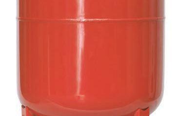
7 PRODUCT RANGE INDUSTRIAS IBAIONDO, HMF series tanks are used as complement of hydrocarbons booster sets (diesel oil pumps) and the membrane is specifically designed for this use. External finish: epoxy powder coating (red color). AMR - SS series are manufactured in stainless steel (AISI 304). DX stainless series and DG galvanized series without membrane are installed in combination of an injector equipment. AHN series (water hammer shock absorbers) are installed in all water pipes to reduce into permissible values overpressure and underpressure waves expanded through the pipes, because of suddenly closing valves or pumps stop/start maneuvers. on the model. Optional magnetic level. The installation of a water hammer shock absorber increase the life of the installations, reduce its costs and guarantees its protection. NOTE: Water shock arrestors designed for waste water are also available.
")


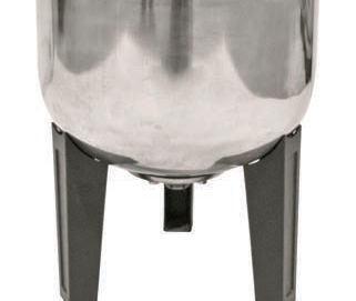
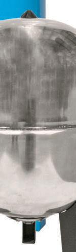
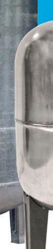
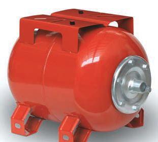
8 IBAIONDO, AMR SERIES Hydropneumatic tanks for booster sets - Replaceable bladder (potable water) - Galvanized threaded connection - Pre-charge: 1.5 bar - External finish: epoxy powder coating (red color) Models without feet Bar Models with feet 8-10 Bar Horizontal models with support 10 Bar
 - Upper inspection hole - Min. / Max. - Pre-charge: 1.")
 Flange connection DN 65 PN16 Manhole Other")
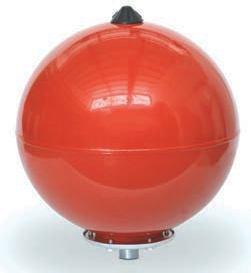
9 IBAIONDO, AMR SERIES Hydropneumatic tanks for booster sets, heating & cooling systems - Replaceable bladder (potable water) - Upper inspection hole - Min. / Max. - Pre-charge: 1.5 bar - External finish: epoxy powder coating (red color) Vertical large models Bar NEW Optional: Threaded connection stainless steel (AISI 316) Flange connection DN 65 PN16 Manhole Other capacities or vertical models, consult factory.
 - Brass or stainless steel (AISI 316) threaded")
 Vertical models")

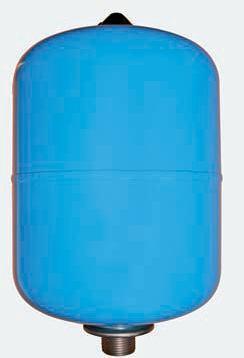
10 IBAIONDO, AMR SERIES Hydropneumatic tanks for booster sets - Replaceable bladder (potable water) - Brass or stainless steel (AISI 316) threaded connection - Min. / Max. - Pre-charge: 1.5 bar - External finish: epoxy powder coating (red color) Vertical models Bar HMF SERIES Hidrocarbons hydropneumatic tanks - Fixed membrane, suitable for hydrocarbons - Pre-charge: 1.5 bar - External finish: epoxy powder coating (red color) Models without feet Bar
INDUSTRIAS IBAIONDO, S.A. PRODUCT GUIDE Expansion vessels. Hydropneumatic tanks. Buffer storage tanks Compressed air tanks
 INUSTIAS POUCT GUIE 2014 Expansion vessels ydropneumatic tanks Buffer storage tanks Compressed air tanks INUSTIAS INEX YOPNEUMATIC TANKS AMF Series... 16 AM - PLUS Series... 17 AM - UO Series... 17 AM
Airfix D-E-B Installation and operating instructions
 www.flamco.nt-rt.ru Airfix D-E-B Installation and operating instructions Dear Customer, With the Airfix D-E-B membrane expansion vessel you have acquired a Flamco quality product. This expansion vessel
Model MTB-ASME Vertical Bladder Tanks
 DATA SHEET Model MTB-ASME Vertical Bladder Tanks Features n UL Listed for use with various proportioners and foam concentrates n 175 psi (12.1 bar) maximum allowable working pressure (design pressure)
Model MTB-ASME Vertical Bladder Tanks
 DATA SHEET Model MTB-ASME Vertical Bladder Tanks Features n UL Listed for use with various proportioners and foam concentrates n 175 psi (12.1 bar) maximum allowable working pressure (design pressure)
Horizontal Bladder Tanks
 DATA SHEET Horizontal Bladder Tanks Features UL Listed and FM Approved for use with various ANSUL proportioners and foam concentrates 175 psi (12.1 bar) maximum allowable working pressure (design pressure)
Vertical Bladder Tanks
 DATA SHEET Vertical Bladder Tanks Features UL Listed and FM Approved for use with various ANSUL proportioners and foam concentrates 175 psi (12.1 bar) maximum allowable working pressure (design pressure)
Model MTB-ASME Horizontal Bladder Tanks
 DATA SHEET Model MTB-ASME Horizontal Bladder Tanks Features n UL Listed and FM Approved for use with various proportioners and foam concentrates n 175 psi (12.1 bar) maximum allowable working pressure
Expansion Vessels for Potable Installations
 4. Expansion Vessels for Potable Installations Domestic installations lose millions of litres of potable water due to expansion water leaking from the vent and expansion pipe. Flamco s Airfix diaphragm
TP1 and TP2 Temporary Cone Shaped Strainers
 1698051/2 IM-P169-07 ST Issue 2 TP1 and TP2 Temporary Cone Shaped Strainers Installation and Maintenance Instructions TP1 1. Safety information 2. General product information 3. Installation and commissioning
AUTOMATIC HOSE TEST UNIT, TYPE SPU
 VALVES AND FITTINGS UP TO 14,000 BAR TEST AND CONTROL EQUIPMENT H IGH PRESSURE TECHNOLOGY AUTOMATIC HOSE TEST UNIT, TYPE SPU Pressure range from 1 up to 10,000 bar User-friendly touch panel operation HIGH-PRESSURE
G type DUCTED EXHAUST SAFETY VALVE 2871 AND 288X SERIES. Model/Ref:
 Model/Ref: 28713 www.lauridsenindustri.com CHARACTERISTICS The G type safety valves are dedicated to protect the equipment from potential overpressure. They are automatic and close when the pressure conditions
Pressure surge absorption
 Pressure surge absorption Product range for drinking water, waste water and the chemical industry With remote monitoring, everything is fully under control. Willy Zahnd, WARET AG PRESSURE SURGE ABSORPTION
Size : Ends : Min Temperature : Max Temperature : Materials : Cast iron body
 Size : Ends : Min Temperature : Max Temperature : DN 40 to DN 300 Flanges R.F. PN10/16-10 C + 80 C Max Pressure : 16 Bars up to DN200 Specifications : Removable stainless steel filter Bolted bonnet with
Spiratec ST14, ST16 and ST17 Sensor Chambers and sensors
 0862050/1 IM-P086-18 MI Issue 1 Spiratec ST14, ST16 and ST17 Sensor Chambers and sensors Installation and Maintenance Instructions 1. Safety Information 2. General product information 3. Installation 4.
Serie ECO 3F. Flanged back flow preventer with controllable reduced pressure zone. made in. Application fields. Protection
 Flanged back flow preventer with controllable reduced pressure zone made in Application fields WATER FIRE FIGHTING DRINKING WATER 64 www.brandoni.it The ECO 3F flanged backflow preventers, which have a
SABERINDO PACIF SABERINDO PACIFIC CIFIC SABERINDO PA. A Tyco International Company
 CIF A Tyco International Company 1 Foam Concentrate CIF 3% AFFF -UL Listed -UL Canada Listed 6% AFFF 6 parts AFFF concentrate to 94 parts water -UL Listed- Foam Liquid -UL Canada Listed 3% FLUOROPROTEIN
BIMBAR INFLATABLE PACKERS AND ACCESSORIES
 BIMBAR INFLATABLE PACKERS AND ACCESSORIES Geopro supplies a complete range of inflatable packers in nine different diameters from 28 up to 170mm. All our packers made of BIMBAR rubber technology are reinforced
Pressure Reducing Valve DMV 755
 Pressure Reducing Valve DMV 755 Nominal size DN 10 50 Nominal size 3/8 2 Nominal pressure PN 10 bar Features pressure setting range 1 to 9 bar control valve for reliable reduction of system pressures to
Differential Pressure Regulator Type Type 45-6 (0.1 to 1 bar, DN 15) Mounting and Operating Instructions EB 3226 EN
 Mounting and Operating Instructions EB 3226 EN") Differential Pressure Regulator Type 45-6 Type 45-6 (0.1 to 1 bar, DN 15) Mounting and Operating Instructions EB 3226 EN Edition March 2008 Contents Contents Page 1 Design and principle of operation...................
Differential Pressure Regulator Type 45-6 Type 45-6 (0.1 to 1 bar, DN 15) Mounting and Operating Instructions EB 3226 EN Edition March 2008 Contents Contents Page 1 Design and principle of operation...................
IX1 Spirax-Monnier International Compressed Air Filter Installation and Maintenance Instructions
 0575050/2 IM-P057-04 CH Issue 2 IX1 Spirax-Monnier International Compressed Air Filter Installation and Maintenance Instructions 1 Safety information 2 General product information 3 Installation and commissioning
Flamco Airfix D-E. Installation and operating instructions. 1999, Flamco eps
 Airfix D-E 6442.eps GB Installation and operating instructions 1999, Exclusion of liability All operation and maintenance related technical information, data and instructions contained in these installation
Measurement accessories METPOINT OCV for the measurement in systems up to 40 bar
 EN - english Instructions for installation and operation Measurement accessories METPOINT OCV for the measurement in systems up to 40 bar Dear customer, Thank you for deciding in favour of the METPOINT
CAST IRON SAFETY VALVE TYPE 6301
 CHARACTERISTICS The 6301 safety valve is dedicated to protect the equipment from potential overpressure. This is an automatic device that closes when the pressure conditions are back to normal. It is a
Size : Ends : Min Temperature : Max Temperature : Materials : Cast iron body
 Size : Ends : Min Temperature : Max Temperature : DN 15 to DN 400 Flanges GN10/16-10 C + 120 C Max Pressure : 16 Bars up to DN 200 ( 10 bars over ) Specifications : Removable stainless steel filter Bolted
6301 TYPE CAST IRON SAFETY VALVES
 Pressure (bar) 6301 TYPE CAST IRON SAFETY VALVES FEATURES The 6301 type safety valve is a device designed to protect installations against possible overpressure. It operates automatically and closes when
Serie ECO 3T. Threaded end back flow preventer with controllable reduced pressure zone. made in. Application fields. Protection E U R O P E
 Serie ECO T Threaded end back flow preventer with controllable reduced pressure zone BRANDONI made in E U R O P E Application fields WATER FIRE FIGHTING DRINKING WATER 74 www.brandoni.it Serie ECO T The
TECHNICAL DATA. TRIMPAC Model B-5 & B-5B
 September 16, 2013 Trimpac 250a 1. DESCRIPTION DEsCRIPTIoN is a factory assembled trim package for a ed an electric/pneumatic release module in a metal enclosure. The standard trim normally required on
Instruction Manual Contact Pressure Vacuum Gauge
 MS10 Instruction Manual Contact Pressure Vacuum Gauge Table of Contents 1. Safety Instructions 2. Intended Applications 3. Product Description and Functions 4. Installation 5. Commissioning 6. Maintenance
TECHNICAL DATA. Trimpac 251a. Spetember 16, 2013
 Spetember 16, 2013 Trimpac 251a 1. DEsCrIpTION DESCRIPTION TRIMPAC Model B-6 and B-6B is a factory assembled trim package for a double interlocked preaction system with an electric/pneu-lectric release
TECHNICAL DATA. Trimpac 257a. September 16, 2013
 September 16, 2013 Trimpac 257a 1. DESCrIpTION DESCRIPTION The Viking Double SUREFIRE SIngle Interlock Preaction TRIMPAC Model D-2 and D-2B used with either a Model E or F Deluge Valve (A.1), a Viking
GUKO FDA. einfach. gut. beraten.
 GUKO FDA Size : Ends : Min Temperature : Max Temperature : DN 25 to 300 Flanges PN10/16-25 C + 90 C Max Pressure : 16 Bars Specifications : Absorb vibrations and noise Linear and angular compansion Inner
Materials : Carbon steel ASTM A216 WCB
 Certificate 3.1 Size : Ends : Min Temperature : Max Temperature : DN 50 to DN 400 ( NPS 2" to 16" ) Flanges R.F. Class 150 (PN20) - 29 C + 425 C Max Pressure : 20 Bars Specifications : Removable stainless
Materials : Dichromate zinc plated steel flanges or AISI 316
 Size : Ends : Min Temperature : Max Temperature : DN 25 to 300 Flanges PN10/16-35 C + 90 C Max Pressure : 16 Bars (10 bars at 90 C) Specifications : Absorb vibrations and noise Linear and angular compansion
Grundfos GT TANK Keep it safe
 GRUNDFOS GT TANK Grundfos GT TANK Keep it safe Long-life tanks for all needs Grundfos pressure tanks are all ideally suited and approved for use with drinking water. The material used ensures that there
Materials : Galvanized steel flanges
 Size : Ends : Min Temperature : Max Temperature : DN 32 to 200 Flanges PN10/16-10 C + 80 C Max Pressure : 16 Bars Specifications : Absorb vibrations and noises Linear and angular compansion Single NBR
Serie 06-M6. Swing wafer check valve. made in. Application fields. Check valves E U R O P E WATER CONDITIONING INDUSTRY
 Swing wafer check valve BRANDONI made in E U R O P E Application fields WATER CONDITIONING INDUSTRY HEATING 38 www.brandoni.it The valves in series 06 are swing wafer check valves, manufactured in accordance
Application and Sizing
 Application and Sizing Energy accumulator: It is improbable that an hydraulic system use all of its capacity without interruptions. An hydropneumatic accumulator can store a certain amount of fluid that
Unit 24: Applications of Pneumatics and Hydraulics
 Unit 24: Applications of Pneumatics and Hydraulics Unit code: J/601/1496 QCF level: 4 Credit value: 15 OUTCOME 2 TUTORIAL 9 ACCUMULATORS The material needed for outcome 2 is very extensive so there are
VERTICAL BLADDER TANK
 Balanced Pressure Proportioning System Reliable Foam System Requiring Only Water Power Perfect For Tight Spaces UL Listed, ASME, National Board Registered Bladder-UL162 Approved, High Tensile Pressure
Materials : Dichromate zinc plated steel flanges
 Size : Ends : Min Temperature : Max Temperature : DN 25 to 300 Flanges PN10/16-35 C + 130 C Max Pressure : 16 Bars up to DN150, 10 bars over Specifications : Absorb vibrations and noise Linear and angular
TECHNICAL DATA. Trimpac 244a. September 16, 2013
 September 16, 2013 Trimpac 244a 1. DEsCrIpTION DESCRIPTION TRIMPAC Model B-1 and B-1B is a factory-assembled trim package with an electric release module in a metal enclosure. The standard trim normally
Installation, Operation and Maintenance Instructions Buffer Vessel OM006
 Installation, Operation and Maintenance Instructions Buffer Vessel OM006 Calorifiers Heat Exchangers Pressurisation Units Sales Tel: 01457 835700 Sales Fax: 01457 832700 E-mail: sales@gmsthermal.co.uk
OFFICINE OROBICHE S.p.A. 1/9
 OFFICINE OROBICHE S.p.A. 1/9 INSTRUCTIONS MANUAL FOR LEVEL SWITCHES SERIES 7000 mod. 7250 AND 7400 Electric 1. INSTRUMENT DESCRIPTION Series 7000 level switches have been designed for external lateral
Size : Ends : Min Temperature : Max Temperature : Materials : Galvanized steel flanges
 Size : Ends : Min Temperature : Max Temperature : DN 32 to 600 Flanges ISO PN10/16-10 C + 100 C for EPDM and + 80 C for NBR Max Pressure : 16 Bars up to DN 300 Specifications : Absorb vibrations and noises
FLUID POWER FLUID POWER EQUIPMENT TUTORIAL ACCUMULATORS. This work covers part of outcome 2 of the Edexcel standard module:
 FLUID POWER FLUID POWER EQUIPMENT TUTORIAL ACCUMULATORS This work covers part of outcome 2 of the Edexcel standard module: UNIT 21746P APPLIED PNEUMATICS AND HYDRAULICS The material needed for outcome
Materials : Electro galvanized steel flanges
 Size : Ends : Min Temperature : Max Temperature : DN 32 to 600 Flanges PN10/16-10 C + 100 C for EPDM and + 80 C for NBR Max Pressure : 16 Bars up to DN 300 Specifications : Absorb vibrations and noises
DCV6 Disc Check Valve
 1342050/6 IM-P134-22 ST Issue 6 DCV6 Disc Check Valve Installation and Maintenance Instructions Printed IM-P134-22 in the UK ST Issue 6 Copyright 20101 Safe operation of this product can only be guaranteed
HUPF Series DESCRIPTION APPLICATION INSTRUCTION SHEET GAS PRESSURE REGULATOR WITH INCORPORATED FILTER EN1C-0003NL05 R1205.
 HUPF Series GAS PRESSURE REGULATOR WITH INCORPORATED FILTER INSTRUCTION SHEET DESCRIPTION Spring-loaded regulator with inlet pressure compensation and zero shut-off. The outlet pressure is kept constant
ATS430 turbidity sensor Retractable insertion assembly
 A MEASUREMENT & ANALYTICS INSTRUCTION ATS430 turbidity sensor Retractable insertion assembly Measurement made easy 1 Introduction This publication details installation procedures for the retractable insertion
KBV21i and KBV40i Key Operated Boiler Blowdown Valves Installation and Maintenance Instructions
 4059051/3 IM-P405-48 EMM Issue 3 KBV21i and KBV40i Key Operated Boiler Blowdown Valves Installation and Maintenance Instructions 1. Safety information 2. General product information 3. Installation 4.
Ref GAS WAFER BUTTERFLY VALVE. Model/Ref:
 Model/Ref: 1141 www.lauridsenindustri.com Size : Ends : Min Temperature : Max Temperature : DN 32/40 to 200 mm Between ISO PN10/16 and ANSI150 flanges - 20 C + 60 C Max Pressure : 5 Bars Specifications
TECHNICAL DATA PILOT PRESSURE REGULATED DELUGE SYSTEM CONTROLLED BY PNEUMATIC RELEASE. 1. DESCRIPTION (Refer to Figures 1, 2 or 3.
 Page 1 of 8 1. DESCRIPTION A Viking Pilot Pressure Regulated Deluge System utilizes a Viking Flow Control Valve to control water flow into the deluge system. The flow control valve must be installed with
Size : Ends : Min Temperature : Max Temperature : Materials : Cast iron EN GJL 250 body. Reinforced lug for DN200 :
 Reinforced lug for DN200 : Size : Ends : Min Temperature : Max Temperature : DN 50 to 200 mm Between flanges ISO PN10/16 ( PN10 for DN200 ) - 10 C + 110 C Max Pressure : 10 Bars Specifications : Long neck
DCV10 Stainless Steel Disc Check Valve for use with Condensate Pumps
 6018050/1 IM-P601-33 ST Issue 1 DCV10 Stainless Steel Disc Check Valve for use with Condensate Pumps Installation and Maintenance Instructions 1. Safety information 2. General product information 3. Installation
Overview of types. T5-R B2/R B2 en v Subject to changes 1 / 4. k vs (Sequence 2)
") Technical data sheet R3015-..-..-B2 / R3020-..-..-B2 Characterised control valves, 6-way, with internal threads Two sequences (cooling/heating) With a rotary actuator 90 Water-side switching or modulating
Technical data sheet R3015-..-..-B2 / R3020-..-..-B2 Characterised control valves, 6-way, with internal threads Two sequences (cooling/heating) With a rotary actuator 90 Water-side switching or modulating
Self-operated Regulators Accessories Differential Pressure and Flow Regulators
 Self-operated Regulators Accessories Differential Pressure and Flow Regulators Compression-type fittings Needle valves Compensation chambers Orifice plates Welding neck flanges Control lines Application
TECHNICAL DATA. Trimpac 256a. October 31, 2013
 October 31, 2013 Trimpac 256a 1. DESCRIPTION The Viking SUREFIRE SIngle Interlock Preaction TRIMPAC Model D-1 and D- 1B used with either a Model E or F Deluge Valve (A.1), a Viking Easy Riser check valve
Airfix. Flamco. Flamco. Pressure expansion vessels for sanitary appliances and potable water systems AIRFIX A AIRFIX D AIRFIX D-E
 AIRFIX EXPANSION VESSELS Flamco Airfix Pressure expansion vessels for sanitary appliances and potable water systems AIRFIX A AIRFIX AIRFIX -E Flamco Edition 2005 / EXP Flamco Flamco offers you a wide choice
Flow controller Type ED/CCB311 Instruction manual
 Flow measurement Flow controller Type ED/CCB311 1. GENERAL DESCRIPTION page 4 2. DETAILED DESCRIPTION page 4 3. PIPE - EXPLOITATION page 5 4. PREVENTIVE MAINTENANCE page 5 5. REPLACEMENT OF THE CONTACT
WATER HEATER THERMAL EXPANSION TANKS Owner s Manual. Safety Instructions Installation Maintenance Warranty. Models: 2-5 Gallon Capacity
 WATER HEATER THERMAL EXPANSION TANKS Owner s Manual Safety Instructions Installation Maintenance Warranty Models: 2-5 Gallon Capacity Thank You for purchasing this Thermal Expansion Tank. Properly installed
VALFONTA INSTRUCTIONS: OPERATION AND INSTALLATION PRESSURE REDUCING VALVE MODEL PRV44
 INSTRUCTIONS: OPERATION AND INSTALLATION PRESSURE REDUCING VALVE MODEL PRV44 Pressure Reducing Valve PRV44 - Operation and Installation - 1 - manual PRV44-16-ENG JULY 2016 INDEX PAGE 1 IDENTIFICATION PLATE
Installation, operation & maintenance manual - original version
 Installation, operation & maintenance manual - original version AVK gate valves for water and wastewater Series 01, 02, 06, 12, 15, 18, 20, 26, 32, 33, 36, 38, 50, 55 and 636 COPYRIGHT AVK GROUP A/S 2018
HORIZONTAL BLADDER TANK
 Balanced Pressure Proportioning System Reliable Foam System Requiring Only Water Power Perfect For Low Ceilings UL Listed, ASME, National Board Registered Bladder-UL162 Approved, High Tensile Pressure
Flanged pressure reducer/stabilizer VRCD
 Flanged pressure reducer/stabilizer VRCD 2 This unit reduces and stabilizes the upstream pressure by operating on its load losses with a constant downstream pressure irrespective of the rate of flow value.
Accessories. Finger Guards 134. Filter Guards grille 139. Accessories 140. Technology. DC Axial Fans. DC Radial Fans. Specials.
 13 Technology Finger Guards 134 Filter Guards grille 139 140 Specials DC Axial Fans DC Radial Fans Everything that you need for your fan. ebm-papst provides an extensive range of accessories for optimum
Materials : Stainless steel ASTM A351 CF8M
 Certificat 3.1 Size: Ends : Min Temperature : Max Temperature : DN 15 to DN 200 PN16 Flanges R.F. - 20 C + 200 C Max Pressure : 16 Bars Specifiations : Removable stainless steel filter Bolted bonnet with
Magnetic level switch type MR783 Instruction Manual
 Magnetic level switch Magnetic level switch type MR783 1. DESCRIPTION page 3 1.1 Operation page 3 1.2 Application page 3 1.3 Description page 3 2. SPECIFICATIONS page 3 2.1 Service Conditions page 4 2.2
Instruction Manual Differential Pressure Transmitter
 DE13 Instruction Manual Differential Pressure Transmitter Table of Contents 1. Safety Instructions 2. Intended Applications 3. Product Description and Functions 4. Installation 5. Commissioning 6. Maintenance
Combined Pressure / Vacuum Relief Valve KITO VD/o
 KITO VD/o DN D H kg* vacuum setting (mbar) pressure DIN ANSI DIN ANSI min max min max** 50 PN 16 2 220 332 351 11 3 50 10 75 80 PN 16 3 260 367 387 145 3 50 10 70 100 PN 16 4 260 368 393 178 3 50 10 80
AVM7 Stainless Steel Thermostatic Air Vent
 1231850/4 IM-P123-23 ST Issue 4 AVM7 Stainless Steel Thermostatic Air Vent Installation and Maintenance Instructions 1. Safety information 2. General product information 3. Installation 4. Commissioning
OPERATING INSTRUCTIONS
 0/05 OPERATING INSTRUCTIONS for gas pressure regulators PN0 with integrated slam shut valve (SSV) and integrated limited capacity safety relief valve (RV) MR 25 F0, MR 25 SF0 p e 20 kpa - 0 MPa (0,2-0
P-04 Stainless Steel Corrugated Hoses and Metal Bellows Expansion Joints
 Guideline No.P-04 (201510) P-04 Stainless Steel Corrugated Hoses and Metal Bellows Expansion Joints Issued date: 20 th October 2015 China Classification Society Foreword This Guideline is a part of CCS
Diaphragm Accumulators
 Diaphragm Accumulators HYDAC Diaphragm Accumulators Index Page 1. Description 3 Introduction 3 Construction 3 2. Applications 4 3. Technical Data 6 Operation 6 Technical Specifications 6 Temperature Effect
C Lite CAD SERIES. ACS Approved. Patented CAD-2 diaphragm technology. Rugged copolymer polypropylene base. Quality brass air stem with o-ring seal
 2 C Lite CAD SERIES Patented CAD-2 diaphragm technology Unique 3 piece construction Reinforced Plastic Connection Durable continuous strand fiberglass sealed with epoxy resin NSF Standard 61, CE/PED, WRAS,
Pressure Reducing Valve DMV 750 set range: bar
 Pressure Reducing Valve DMV 750 set range:.0-6.0 bar Advantage pressure setting possible at any time, also during operation hermetically sealed by valve diaphragm high level of operating safety and long
TECHNICAL DATA MAINTENANCE AIR COMPRESSOR MODEL G-1
 Dry 131h 1. DESCRIPTION The Viking Model G-1 Maintenance Air Compressor is an electric motor-driven, aircooled, single-stage, oil-less compressor. The unit is equipped with a check valve and provides a
Technical data sheet. Type overview. Technical data. Safety notes. T5-R2.. Open-close en v Subject to changes 1 / 3
 Technical data sheet R2.. Open-close ball valves, 2-way, with internal thread for open and closed cold and warm water systems for shut-off functions on the water side and 2-point controls in air-handling
Differential Pressure Control Valve (DPCV)
") Differential Pressure Control Valve (DPCV) PATENTED Technical Data and Installation Instructions Page 1 V2 The modulating valves ART 241 balance and control the differential pressure (DPCV) automatically
Differential Pressure Control Valve (DPCV) PATENTED Technical Data and Installation Instructions Page 1 V2 The modulating valves ART 241 balance and control the differential pressure (DPCV) automatically
Gas powered stop valves, type GPLX REFRIGERATION AND AIR CONDITIONING. Technical leaflet
 Gas powered stop valves, type GPLX 80-150 REFRIGERATION AND AIR CONDITIONING Technical leaflet Technical leaflet Gas powered stop valves, type GPLX 80-150 Contents Page Introduction........................................................................................3
KBV21i and KBV40i Air Actuated Boiler Blowdown Valves
 4059051/1 IM-P405-48 AB Issue 1 KBV21i and KBV40i Air Actuated Boiler Blowdown Valves Installation and Maintenance Instructions 1. Safety information 2. General product information 3. Installation 4. Commissioning
CVS10 Sanitary Check Valves
 0299050/4 IM-P029-11 ST Issue 4 CVS10 Sanitary Check Valves Installation and Maintenance Instructions 1. Safety information CVS10 with soft seat 2. General product information 3. Operation 4. Installation
INSTRUCTION MANUAL Pressure Relief Device LPT
 INSTRUCTION MANUAL Pressure Relief Device LPT 5COV475800 LPT REV00 CONTENT: 1 SAFETY 1.1 Safety instructions 2 1.2 Specified applications 2 1.3 Safety notes on the equipment operation 2 2 PRESSURE RELIEF
PULSATION DAMPENER / SUPPRESSOR SERIES PDS PROVIDES MULTIPLE SYSTEM SAFEGUARDS
 PULSATION / SUPPRESSOR SERIES PDS PROVIDES MULTIPLE SYSTEM SAFEGUARDS FUNCTIONS: 1. Pulsation Dampener smooths pump flow 2. Surge Suppressor absorbs shocks and vibrations 3. Water Hammer Arrestor eliminates
Installation, commissioning and servicing instructions
 48323 www.caleffi.com Pre-adjustable pressure reducing valve with self-contained cartridge Copyright 2015 Caleffi 5350..H AUS series Installation, commissioning and servicing instructions Function Pressure
TECHNICAL DATA SINGLE INTERLOCKED PREACTION SYSTEM WITH PNEUMATIC RELEASE
 1 of 10 1. DESCRIPTION (Refer to Figures 1-3.) Viking supervised Single Interlocked Preaction Systems utilize a Viking Deluge Valve and a pneumatically pressurized automatic sprinkler system. The system
Pressure Independent Control Series
 Document No. 155-522 Pressure Independent Control Series Two-Way Cast Iron Flanged Bodies, ANSI 125 and 250 Description Siemens Pressure Independent Control Valves integrate three functions into a single
Steam Trap BK 15 (DN40, DN 50) Original Installation Instructions English
 Original Installation Instructions English") Steam Trap BK 15 (DN40, DN 50) EN English Original Installation Instructions 810682-03 1 Contents Page Important Notes Usage for the intended purpose... 4 Safety note... 4 Danger... 4 Attention... 4 Application
Steam Trap BK 15 (DN40, DN 50) EN English Original Installation Instructions 810682-03 1 Contents Page Important Notes Usage for the intended purpose... 4 Safety note... 4 Danger... 4 Attention... 4 Application
TECHNICAL DATA. Page 1 of 12
 Page 1 of 12 1. DESCRIPTION The Viking Regulating Valve is a direct-acting, single-seated, spring-loaded diaphragm valve. When installed as a pilot regulating valve on a Viking Model H or J Flow Control
6-5 Maintenance Manual
 Non Return Valve 6-5 Maintenance Manual Contents 1. PRODUCT DESCRIPTION... 1 1.1 How it works... 1 1.2 Overall dimensions... 3 1.3 Technical datasheet... 4 1.3.1 Push flow situation... 4 1.3.2 Pull flow
Vibration isolated tables. Individually tailored to your requirements.
 68 Vibration isolated tables Individually tailored to your requirements. LTH laboratory table Particularly robust and resistant n Adjustable leveling mounts n Rigid, welded steel subframe n BiAir membrane
Pipe Thread Connection 1/2 inch NPT. Friction Loss Refer to Figure 3
 Worldwide Contacts www.tyco-fire.com Model B-1 Pipe Line Strainer General Description The Model B-1 Pipe Line Strainers (Ref. Figures 1 and 2) are designed for installation in the water supply connection
National Marine Manufacturers Association
 1. All of the following would be considered as a compliant seacock except a. an in-line ball valve with a lever type handle operating through a 180 arc b. a flanged sea valve which mounts directly to the
Manual Actuated Boiler Blowdown Valves
 Manual Actuated Boiler Blowdown Valves Installation and Maintenance Instructions 1. Safety information 2. General product information 3. Installation 4. Operation 5. Maintenance 6. Spare parts p.1 1. Safety
DCV1, DCV3 and DCV3LT Disc Check Valves Installation and Maintenance Instructions
 1340050/7 IM-P134-07 CMGT Issue 7 DCV1, DCV3 and DCV3LT Disc Check Valves Installation and Maintenance Instructions 1. Safety information 2. General product information 3. Installation 4. Commissioning
Installation, Operation and Maintenance Manual for Back Pressure Regulator
 Installation, Operation and Maintenance Manual for Back Pressure Regulator Model 8860 2009 Groth Corporation IOM-8860 Rev. B 12541 Ref. ID: 95565 Page 2 of 13 Table of Contents I. INTRODUCTION 3 II. DESIGN
Type overview. R B2 en-gb subject to changes 1
 Technical data sheet R30..-..-..-B2 Characterised control valve, 6-way, Internal thread Two sequences (cooling/heating) with one 90 rotary actuator Switching or modulating control on the water side of
HERZ - Compact Flow Controller with
 HERZ - Compact Flow Controller with Integrated Control Valve Data sheet for flanged compact PIBCV PN 16, Issue 0616 Dimensions in mm min. 200 mm control valve cone valve seat H flow controller cone actuator
InnovDos Foam proportioning system
 InnovDos Lorrie 9 NL - 1724 BL Oudkarspel T: +31 88 9112 112 F: +31 88 9112 119 info@innovfoam.com www.innovfoam.com 1 1. General Information System Composition The InnovDos is made up of two main components
Automatic balancing valves ASV
 Automatic balancing valves ASV ASV-P ASV-PV ASV-PV ASV-PV ASV-I ASV-M 15-40 15-40 50 65-100 15-50 15-50 Description / Application ASV balancing valves are used for dynamic hydronic balance in heating and
InnoVfoam B.V. InnovDos Foam Proportioning System
 1724 BL Oudkarspel F. +31 (0)88 9112 119 info@innovfoam.com 1 1. GENERAL INFORMATION SYSTEM COMPOSITION The InnovDos system is made up of two main components (see flow schedule on page 4) that can be integrated