INDUSTRIAS IBAIONDO, S.A. PRODUCT GUIDE Expansion vessels. Hydropneumatic tanks. Buffer storage tanks Compressed air tanks
|
|
|
- Phillip Lloyd
- 5 years ago
- Views:
Transcription


1 INUSTIAS POUCT GUIE 2014 Expansion vessels ydropneumatic tanks Buffer storage tanks Compressed air tanks
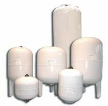
2 INUSTIAS INEX YOPNEUMATIC TANKS AMF Series AM - PLUS Series AM - UO Series AM Series MF Series AM SS Series G Series X Series AN Series Accesories & Spare parts EXPANSION VESSELS CMF Series AM-C-A Series AM-B-A / AM- Aux Series CM Series SMF/SM Series PC/P Series VI Series Accesories & Spare parts BUFFE STOAGE TANKS AN COMPESSE AI TANKS A - A Series PF/PF Series ACET Series ACES Series C Series Spare parts
3 INUSTIAS 2
4 3 INUSTIAS

5 INUSTIAS 4


6 INUSTIAS YOPNEUMATIC TANKS FO BOOSTE SYSTEMS AN WATE AMME ABSOBES EXPANSION VESSELS FO EATING, SW AN SOLA SYSTEMS BUFFE TANKS FO SOLA, COOLING AN COMPESSE AI SYSTEMS 5


7 INUSTIAS IBAIONO IN TE WOL EUOPE AMEICA AFICA OCEANIA ASIA Germany Andorra Belgium Bulgaria Cyprus enmark Spain Finland France Greece olland ungary United Kingdom Ireland Italy Norway Poland Argentina Chile Ecuador Peru Puerto ico Uruguay Venezuela Mexico Algeria Egypt Mali Morocco Mauritania Tunisia INUSTIAS Australia Saudi Arabia United Arab Emirates Bahrein China South Korea ong Kong India Iran Kuwait The Lebanon Qatar Singapur Sri Lanka Thailand Jordan Portugal omania Sweden Switzerland 6


8 INUSTIAS YOPNEUMATIC TANKS 7
9 INUSTIAS INTOUCTION ydropneumatic tanks are designed to be used in potable water supply installations as a part of the pressure booster set in order to ensure the adequate water supplies to buildings, houses, etc. Apart from keeping a pressurized water stock, the hydropneumatic tanks allow a longer life of the pumping unit due to the reduction of the starting and stopping operations involving a significant energy saving. ydropneumatic tanks are manufactured by Industrias Ibaiondo, S.A, according to the safety standards of the European 97/23/EC irective required for pressure units, guaranteeing the use of high quality materials and the proven experience of a highly skilled staff. The most important technical features of the hydropneumatic tanks and any other information related to manufacturing is shown on the identification label attached to the product. This label must not be changed or removed in any case. Every tank is also supplied with the operating instructions manual and the EC conformity certificate. ESCIPTION Steel tanks manufactured according to the European 97/23/EC irective regulations for pressure units. They are made with two embedded roots and a curved metal plate joined together by welding flanges and suitable to withstand loosely design working pressure. The tightness and resistance of the tanks are tested at 1.5 times higher than the maximum working pressure. The hydropneumatic tanks have inside a synthetic rubber bladder manufactured according to the physicalchemical features and to the legal requirements for sanitary water gathered in the IN 4807 Norm. Bladders isolate permanently water from air/ nitrogen and they are designed to be almost entirely filled with water and to fit the shape of the tanks (maximum volumetric expansion), so that they ensure minimum elongation and prevent the material wear. This differential factor along with the thickness and composition of the manufacturing material guarantee the minimum loss of the tank precharge pressure. The threaded (IN-259) or flanged (En 1,092-1) water s are properly protected from corrosion. The bladder water tanks are provided with a valve for the pressure regulation of the air/nitrogen chamber. The outer coating consists of a minimum of 40 microns thick oven cured paint applied on the phosphated steel. 8
10 INUSTIAS OPEATION The drinking water collected directly from the water system, also from the pressure tanks series AM-UO, G or X is driven to the storage water tank by the pumping set. As the water enters the hydropneumatic tank, it is stored inside the bladder which separates tightly the water chamber from air/nitrogen chamber. This water inflow, causes a reduction of the initial volume of the enclosed air/ nitrogen in the tank which involves a pressure increase. When desired maximum pressure has been reached (stop pressure of the pump), the pressure switch, cuts power and the flow of water between the pump and the tank is stopped at this time. The stored energy of the enclosed air/ nitrogen inside the tank will lead the water inside the membrane to the consumption sites according to user needs. As the water flows and the bladder empties, the air/nitrogen pressure decreases till reaching the minimum set pressure (starting pressure of the pump). At that moment, the water feed flows again from the pumping set to the hydropneumatic tank. This cycle runs automatically as long as the minimum and maximum pressures are reached. 9
 Pa: Pump start pressure (Absolute) Pc: Precharge pressure (Absolute) It is suggested Pc=Pa - 0.")
 and pressure switches working with the following values: Pump")
11 INUSTIAS YOPNEUMATIC TANK VOLUME CALCULATION In order to obtain the volume of the hydropneumatic tank, it is necessary to know the following parameters: Q: Average flow of the pump in liters / minute. Zmax: imum pump-starting frequency allowed per hour. Pp: Pump stop pressure (Absolute) Pa: Pump start pressure (Absolute) Pc: Precharge pressure (Absolute) It is suggested Pc=Pa P= Pp- Pa The volume of the tank will be calculated according to: YOPNEUMATIC TANK USEFUL VOLUME CALCULATION The volume of available water V into the hydropneumatic tank between stop and start pump pressure can be calculated as follows: Example: We have an overpressure installation equipped with a 300 lts/min flow pump (5 lts/sec) and pressure switches working with the following values: Pump starting pressure Pa = 3 Bar Pump stopping pressure Pp = 6 Bar imum pump - starting frequency allowed per hour Zmax = 12 The useful water volume: V SELECTION CAT OF YOPNEUMATIC TANK EPENING ON USEFUL WATE VOLUME Switch minimum prressure Bar Switch minimum prressure Bar NOTE: In order to calculate pressure tanks without bladder or water hammer arrestors consult factory. 10
12 INUSTIAS INSTALLATION & ASSEMBLY Before proceeding to the assembly, it is necessary to ensure that the volume of the hydropneumatic tank has been correctly calculated by the authorized technical staff, taking into account the booster set features. ydropneumatic tank must be mounted by a professional installer bearing in mind the instructions provided with the product and the label. ydropneumatic tank needs to be installed in a weather protected place which disposes of the necessary access dimensions in order to facilitate tank inspection. Air valve, sleeve and label must be easy to check. In the case of hydropneumatic tanks without feet or bracket, fastening system will be designed to be able to hold the tank weight completely full of water. Safety valve and manometer must be compulsorily installed. Safety valve will be calibrated according to the maximum system pressure and never higher to the maximum allowable pressure of the tank. ydropneumatic tanks, depending on the model selected, will be connected straight to the pipe line at the lower side of the pump or directly on the pipe line at the pump impulsion. 11
13 INUSTIAS COMMISSIONING ydropneumatic bladder tanks are supplied from the factory with a pre-charge pressure indicated on the label added on product. owever, in order to guarantee the right performance of the system, this value must be adjusted taking into account the characteristics of the installation: In the case of hydropneumatic tanks placed at the impulsion (igh side) of the booster system, pre-charge value will be as follows: Pre-charge = Pump start pressure 0,2 Bar In the case of the hydropneumatic tanks placed at the aspiration (Lower side) of the booster system, pre-charge value will be as follows: Pre-charge = Pump start pressure 0,3 Bar If the pre-charge value is higher than the precharge pressure to which it has been supplied from the factory, previously to the air recharging operation, it will be necessary to introduce water through the inlet/outlet of the tank until cover the bottom coupling. Not to proceed in this way, could result in damage to the membrane as consequence of its extrusion. Once first step is done, we will isolate the hydropneumatic tank of the driving through closing the valve provided for this purpose. From this moment, air recharging will be made through the inflating valve of the tank, until pre-charge pressure is reached. Once pressure is adjusted, tank will be connected to the installation. Once the tank is connected, it works automatically MAINTENANCE Maintenance must be carried out exclusively by authorized staff. At least once a year, pre-charge pressure of the air/nitrogen side needs to be checked to confirm that it is between the right values indicated in previous points. Temperature contrasts should be similar. For that, it will be necessary to close the valve which communicates the tank with the installation and then empty the water of the tank. In case of the pre-charge and measured pressure varies around 20%, it needs to be adjust to the original value, pre-charge pressure, following the instructions pointed in previous points. ISASSEMBLY In no case the tank will be disassembly without depressurizing and emptying the system. In case that working pressure is higher than 3 bar, precautions must be taken to prevent the extrusion of the membrane. 12
14 PALLETIZING INUSTIAS AM / AMF / MF SEIES (no feet) / eference Units / Pallet 5 AM / 5 AMF / / pcs. 8 AM / 8 AMF / pcs. 15 AM / 12 AMF / pcs. 20 AM / 20 AMF / pcs. 24 AM - E / 25 AMF / / pcs. 35 AM / 35 AMF / pcs. 50 AM / 50 AMF / pcs. 1 MF pcs. 2 MF / 5 MF / pcs. 8 MF pcs. 15 MF pcs. 25 MF pcs. AM / AMF SEIES (horizontals) / eference Units / Pallet 20 AM-S / 20 AMF-S / pcs. 50 AM-S / 50 AMF-S / pcs. 80 AM-S pcs. 100 AM-S pcs. AM / AMF / AM-PLUS / AM-UO SEIES (verticals) / eference Units / Pallet 35 AM-P / 35 AMF-P / pcs. 50 AM-P / 50 AMF-P / pcs. 80 AM-P pcs. 80 AM-PLUS pcs. 100 AM-P / 100 AM-P-A / pcs. 150 AM-B90 (M/F) pcs. 200 AM-B90 (M/F) pcs. 300 AM-B160 (M/F) pcs. 500 AM-B160 (M/F) pcs. 100 AM-16 Bar / 100 AM-PLUS / pcs. 150 AM-PLUS / 150 AM-UO / pcs. 220 AM-PLUS / 220 AM-UO / pcs. 13
 according to IN 4807. Stainless steel water (1 ). imum pressure: 8-10 bar. Min / temperature: -10 ºC + 100ºC. Pre-charge pressure: 3 bar (nitrogen).")

.")
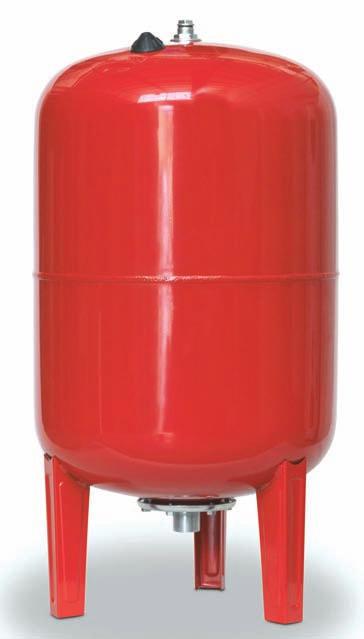
15 INUSTIAS POUCT ANGE AMF series tanks are manufactured to guarantee a long life of the pressure booster sets. Volume: 2-50 liters. s: no feet / with feet / horizontal with bracket. Non-replaceable butyl membrane (bladder) according to IN Stainless steel water (1 ). imum pressure: 8-10 bar. Min / temperature: -10 ºC + 100ºC. Pre-charge pressure: 3 bar (nitrogen). External finish: epoxy powder coating, suitable for outdoor (blue color AL 5012). esigned and manufactured according to 97/23/EC irective. AM-PLUS series tanks incorporate improvements comparing with conventional AM series. All improvements are leaded to increase the correct performance and to reduce maintenance. Volume: liters. s: vertical / horizontal eplaceable bladder, suitable for potable water, specially designed in dimensions and thickness to get adapted without stretching to the total volume of the tank (IN 4807). 1 brass threaded. 1 threaded upper cup with special coating against corrosion. Min / temperature: -10 C +70 C. imum pressure: 10 bar. Pre-charge pressure: 3 bar (nitrogen). External finish: epoxy powder coating (blue color AL 5012), suitable for outdoor. esigned and manufactured according to 97/23/EC irective. AM-UO series tanks are designed to be installed at the lower side of pressure booster systems as alternative solution to the conventional open tanks in order to guarantee the sanitary conditions of the system. Volume: liters. s: vertical They are provided with two water s of 1 1/2 in stainless steel (AISI 316-L): upper side (water inlet) and lower side (water outlet) to ensure the full flowthrough. eplaceable bladder suitable for potable water (IN 4807). Min / temperature: -10 C +100 C. Pre-charge pressure: 3 bar (nitrogen). External finish: epoxy powder coating (blue color), suitable for outdoor. esigned and manufactured according to 97/23/EC irective. AM series tanks with: Volume: liters. s: no feet / with feet / vertical / horizontal /high pressure / big tanks eplaceable membrane (bladder) according to IN 4807 for potable water. Min / temperature: -10 ºC + 100ºC. imun pressure: 10 bar. Pre-charge pressure: 1,5 bar. 100 AM-P-A to 700 AM-B 160: upper threaded coupling ( GM G) AM to 8000 AM in 6,10 and 16 bar with inspection hole on the top, manometer and drain valve. 2 2 s (painted or stainless steel): top attachment with stainless steel threaded External finish: epoxy powder coating (red color). esigned and manufactured according to 97/23/EC irective. 14

 according to IN 4807 for potable water. Threaded water in stainless steel (AISI 304). Min / temperature: -10ºC + 100ºC.")


16 POUCT ANGE INUSTIAS MF series tanks are used as complement of hydrocarbons booster sets (diesel oil pumps) and the membrane is specifically designed for this use. Volume: 1-25 liters. No feet models. Fixed membrane, according to IN 4807, suitable to contain hydrocarbons. imum pressure: bar. Min / temperature: - 10 ºC ºC. Pre-charge pressure: 1,5 bar. External finish: epoxy powder coating (red color). esigned and manufactured according to 97/23/EC irective. AM - SS series are manufactured in stainless steel (AISI 304). Volume: liters. s: no feet / with feet / with bracket eplaceable membrane (bladder) according to IN 4807 for potable water. Threaded water in stainless steel (AISI 304). Min / temperature: -10ºC + 100ºC. imum pressure: 10 bar. Pre-charge pressure: 1,5 bar. esigned and manufactured according to 97/23/EC irective. X stainless series and G galvanized series without membrane are installed in combination of an injector equipment. Volume: liters. Vertical models. orizontal models consult in factory. X series are manufactured in stainless steel (AISI 304 or AISI 316) without bladder. G series are manufactured in hot galvanized steel without bladder. Set of connectors (female thread). Min / temperature: -10ºC +100ºC. imum pressure: 8-10 bar. esigned and manufactured according to 97/23/EC irective. AN series (water hammer shock absorbers) are installed in all water pipes to reduce into permissible values overpressure and underpressure waves expanded through the pipes, because of suddenly closing valves or pumps stop/start maneuvers. Volume: 0, liters. s: orizontal / Vertical. eplaceable membrane (bladder) according to in 4807 for potable water. Threaded or flanged water depending on the model. Min / temperature: - 10 ºC +100ºC. imum pressure: bar. External water level indicator, isolating and drainage valve depending on the model. Optional magnetic level. esigned and manufactured according to 97/23/EC irective. The installation of a water hammer shock absorber increase the life of the installations, reduce its costs and guarantees its protection. NOTE: shock arrestors designed for waste water are also available. 15
 s without feet 8-10")

17 INUSTIAS AMF SEIES ydropneumatic tanks for any type of booster sets - Non-replaceable butyl membrane (Bladder) - Min. /. temperature: -10ºC + 100ºC - Pre-charge: 3 bar nitrogen - Cover and sleeve in stainless steel - External finish: Epoxy powder coating, suitable for outdoor (blue color AL 5012) s without feet 8-10 Bar 0, AMF " 2 2, AMF " AMF " 3, AMF " AMF , AMF AMF AMF s with feet 10 Bar AMF-P " AMF-P " orizontal models 10 Bar L 6 12 L AMF-S " AMF-S " 16


18 AM - PLUS SEIES idropneumatic tanks for booster sets (igh side) - eplaceable bladder (potable water) - Brass threaded - 1 upper cap and sleeve with especial coating against corrosion Vertical models 10 Bar INUSTIAS - Min. /. temperature: -10 C C - Pre-charge: 3 bar nitrogen - External finish: epoxy powder coating (blue color AL 5012), suitable for outdoor AM-PLUS / 2 New AM-PLUS / 2 " AM-PLUS / 2 " AM-PLUS / 2 " AM-PLUS / 2 " AM-PLUS / 2 " AM-PLUS / 2 " AM-PLUS / 2 " AM-PLUS / 2 orizontal models 10 Bar L AM-PLUS / 2 " AM-PLUS / 2 " AM-PLUS / 2 " New 1 L AM-PLUS / 2 " AM-PLUS / 2 " AM-PLUS / 2 " AM-PLUS / 2 AM - UO SEIES ydropneumatic tanks for booster sets (Lower side) - eplaceable bladder (potable water) - Pre-charge: 3 bar nitrogen - Stainless steel threaded s (AISI 316) - External finish: epoxy powder coating (Upper and bottom) (blue color AL 5012), suitable for outdoor - Min. /. temperature: -10 C C AM-UO x 1 1 / 2 " AM-UO x 1 1 / 2 " AM-UO x 1 1 / 2 " AM-UO x 1 1 / 2 " AM-UO x 1 1 / 2 " AM-UO x 1 1 / AM-UO x 1 1 / 2 New 17
 s without feet 8-10 - 16 Bar 2 2 2,5 4 4,5 9 10 01005013 5 AM 5 10 200 245 3 / 4 01005014 5 AM 5 10 200 245 1 \" 01008021 8 AM 8 10 200 350 1")

 300 10 650 1180 1 1 / 4 71 03500801 500 AM-B160 (M/F) 500 10 750 1450 1 1 / 2 78 03700501 700 AM-B160 (M/F) 700 8 750 1750 1 1 / 2 orizontal models with support 10 Bar 6 12 16 L (mm 01020281 20")
19 INUSTIAS AM SEIES ydropneumatic tanks for booster sets - eplaceable bladder (potable water) - Galvanized threaded - Min. /. temperature: -10 C C - Pre-charge: 1.5 bar - External finish: epoxy powder coating (red color) s without feet Bar 2 2 2,5 4 4, AM / AM " AM " AM " AM AM " AM AM " 4, AM-E / 4 " 4, AM-E s with feet 8-10 Bar AM-P " AM-P " AM-P " AM-P " AM-P-A / AM-B90 (M/F) / AM-B90 (M/F) / AM-B160 (M/F) / AM-B160 (M/F) / AM-B160 (M/F) / 2 orizontal models with support 10 Bar L (mm AM-S " AM-S " AM-S " L AM-S " 18
 Vertical large models 6-10 -16 Bar 260 340 545 650 830 985 1090 1310 01100031 1000 AM 1000 6 850 2225 2\" 01140031 1400 AM 1400 6 1000 2210 2\"")
20 INUSTIAS AM SEIES ydropneumatic tanks for booster sets, heating & cooling systems - eplaceable bladder (potable water) - Upper inspection hole - Min. /. temperature: -10 C C - Pre-charge: 1.5 bar - External finish: epoxy powder coating (red color) Vertical large models Bar AM " AM " AM /2" AM /2" AM /2" AM /2" AM /2" AM /2" NEW AM " AM " AM /2" AM /2" AM /2" AM /2" AM /2" AM /2" AM " AM " AM /2" AM /2" AM /2" AM /2" AM /2" AM /2" Optional: Threaded stainless steel (AISI 316) Flange N 65 PN16 Manhole Other capacities or vertical models, consult factory. 19
 Vertical models 16-20 Bar 33 55 62 79 165 233 341 500 625 70 90 153 234 328 605 666 05100031 100 AM 100 16 485 805 1 1 / 2 05150031 150 AM")

21 INUSTIAS AM SEIES ydropneumatic tanks for booster sets - eplaceable bladder (potable water) - Brass or stainless steel (AISI 316) threaded - Min. /. temperature: -10 C C - Pre-charge: 1.5 bar - External finish: epoxy powder coating (red color) Vertical models Bar AM / AM / AM / AM / AM / AM / AM / AM AM AM / AM / AM / AM / AM / AM AM MF SEIES idrocarbons hydropneumatic tanks - Fixed membrane, suitable for hydrocarbons - Min. /. temperature: -10 C C - Pre-charge: 1.5 bar - External finish: epoxy powder coating (red color) s without feet Bar 1 1,5 2 2,5 3,2 4, MF / MF / MF / MF / MF / MF /4 20


22 AM-SS SEIES ydropneumatics tanks AISI 304 for booster sets - eplaceable bladder (potable water) - Min. /. temperature: -10 C C - Pre-charge: 1.5 bar - tanks manufactured in stainless steel INUSTIAS s without feet 8-10 Bar 4,5 4,5 4, AM polished 24 AM-E polished 24 AM-E blasted AM polished s with feet 10 Bar AM-P polished 100 AM-P polished orizontal models with support 10 Bar AM-S polished 50 AM-S polished 100 AM-S polished L L 21
23 INUSTIAS G SEIES Galvanized water pressure tanks - tanks without membrane - Min. /. Temperature: -10 C + 60 C - Manufactured in hot galvanized steel Vertical models 8 Bar Connection a - u v -s b c G / / 2 1 / / G / / 2 1 / / G / / 2 1 / / Connection a - u v -s b c G / 2 1 / / G / 2 1 / / G / 2 1 / / G / / 2 1 / / G / / / G / / G / / G / / 2 (*) For tanks from liters 22

24 G SEIES Galvanized water pressure tanks - tanks without membrane - Min. /. Temperature: -10 C + 60 C - Manufactured in hot galvanized steel INUSTIAS Vertical models 10 Bar Connection a - u v -s b c G / / 2 1 / / G / / 2 1 / / G / / 2 1 / / G / / 2 1 / / G / / 2 1 / / G / / 2 1 / / Connection a - u v -s b c G / 2 1 / / G / 2 1 / / G / 2 1 / / G / / 2 1 / / G / / / G / / G / / G / / 2 (*) For tanks from liters consumption 23
 - Optional (AISI 316) Vertical models 10 Bar (Industrial finish) 32 46 71 82 105 141 190 270 Connection a - u v -s b")
25 INUSTIAS X SEIES Stainless steel water pressure tanks - tanks without membrane - Min. /. Temperature: -10 C C - tanks manufactured in stainless steel (AISI 304) - Optional (AISI 316) Vertical models 10 Bar (Industrial finish) Connection a - u v -s b X / / 4 1 / X / / 4 1 / X / / 2 1 / X / / 2 1 / X / / 2 1 / X / / 2 1 / X / / 2 1 / X / / 2 1 / Connection a - u v -s-d b X / 2 1 / X / 2 1 / X / / 2 1 / X / / 2 1 / X / 2 1 / 2 (*) For tanks from liters Vertical models 10 Bar (Blasted finish) S 32 Connection a - u v -s b G 100 X / / 4 1 / 2 b G 200 X / / 4 1 / G 300 X / / 2 1 / G 400 X / / 2 1 / 2 b b b G 500 X / / 2 1 / G 600 X / / 2 1 / G 750 X / / 2 1 / 2 u G 1000 X / / 2 1 / 2 V 24
 0,5 07000691 V-160 0,16 16 85 105 1 / 2 s without feet 20-25 - 30 Bar - eplaceable bladder, suitable for potable water - Min. /. temperature: -10 C + 100 C - Pre-charge: 3.")

26 AN SEIES hammer shock absorbers INUSTIAS Miniflex model 16 Bar - Fixed membrane, suitable for potable water - Min. /. temperature: -10 C C - Pre-charge: 3.5 bar - Manufactured in stainless steel (AISI 304) 0, V-160 0, / 2 s without feet Bar - eplaceable bladder, suitable for potable water - Min. /. temperature: -10 C C - Pre-charge: 3.5 bar - External finish: epoxy powder coating (red color) 14,5 29, /N AN AN AN N AN N AN N /N AN AN N AN N AN N /N AN AN N AN N AN N 100 /N 25
,purge and isolating valve - Optional: Magnetic level indicator - External finish: epoxy powder coating (red color) Vertical models 10-16 -")

27 INUSTIAS AN SEIES hammer shock absorbers - eplaceable bladder, suitable for potable water - Min. /. temperature: -10 C C - level indicator set (external),purge and isolating valve - Optional: Magnetic level indicator - External finish: epoxy powder coating (red color) Vertical models Bar N AN-P N AN-P N AN-P N AN-P N AN-P N N AN-P N AN-P N AN-P N AN-P N AN-P N N AN-P N AN-P N AN-P N AN-P N AN-P N 100 N Vertical models Bar N AN-P N AN-P N AN-P N AN-P N AN-P N 150 N AN-P N AN-P N AN-P N AN-P N AN-P N N AN-P N AN-P N AN-P N AN-P N AN-P N 150 NOTE: For larger volumes, consult factory. 26
 19000001 PUMP SEAT - 0")


28 ACCESOIES AN SPAE PATS For better identification consult factory INUSTIAS Collectors (galvanized) Ø d Ø d1 A mm B mm / / / Supports (galvanized) PUMP SEAT PUMP SEAT - 1B ELECTIC BOA SUPPOT AM / AM - SS Membranes ef. d AM/E AM-E AM-E-E x AM x AM - P/S AM-P/S AM-P/S d M Membranes ef. d N 5 M - E NB M - E d 27


29 INUSTIAS ACCESOIES AN SPAE PATS For better identification consult factory AM / AM-PLUS / AM-UO Membranes ef. d AM - P - A AM - B AM - B /700 AM - B ef. AN Membranes d AM - 16 / AM - PLUS AM - PLUS / UO AM - PLUS / UO AM - PLUS / UO AM - PLUS / UO x AM ef. d AN AN AN AN d d d NOTE: For other volumes, consult factory. Valves AM AN / AM > 16 bar AM Special AM - INOX AM AM Special AN / AM > 16 bar 28


 1000-1400 100-1000 10-16 - 20 10-16 2")
30 ACCESOIES AN SPAE PATS For better identification consult factory Lower flanges for water inlet Bar INUSTIAS Top flanges for accesories iameter Ø Connection AM-E / AM / M-E / AM-E/M 3 / AM-E AM / AM-S / AM-P AM AM-P-A / AM-B / AM-B / AM-B / SS iameter Ø AM FLANGE + CUP Connection AM - PLUS FLANGE + CUP AM / AM AM Bladder fastening Coupling Nut Cap AM-P-A AM B90 / B160 inlet coupling Bar Connection / 4 Connection Coupling AN Nut AM / AM- / AM - PLUS / Coupling Locknut Nut seat Coupling Nut AM / AM- SS (AISI 316) / 2 29
31 INUSTIAS NOTES 30

32 INUSTIAS EXPANSION VESSELS 31


33 INUSTIAS INTOUCTION Expansion vessels are designed to be used in atmospheric closed circuits with non corrosive water in order to absorb water dilatations produced by the temperature variations of the heating fluid. They are, therefore, designed to compensate the water volume increases, avoiding the system pressure to overpass the nominal pressure of its components. Expansion vessels are manufactured by Industrias Ibaiondo, S.A, according to the especial safety requirements established by the 97/23/EC irective for pressure systems, employing high quality materials, procedures and qualified and authorized staff. ESCIPTION Steel tanks manufactured according to the European 97/23/EC irective regulations for pressure units. They are made with two embedded roots and a curved metal plate joined together by welding flanges and suitable to withstand loosely design working pressure. The tightness and resistance of the tanks are tested at 1.5 times higher than the maximum working pressure. Expansion vessels have inside a synthetic rubber bladder manufactured according to the physical and mechanical features of the European Norm. Bladders or membranes holding in permanent isolation the water from the air, are calculated to be filled of water until fitting the geometric shape of the expansion vessel guaranteeing a minimum elongation and avoiding material wear. This factor, joined to material thickness and composition which they are made of, ensure a minimum loss of the precharge pressure of the expansion vessel. Vessels are provided with a duly protected valve for the right pressure regulation of the air side. External coating consists in the application over the steel, previously phosphated, of a minimum of 40 microns of oven cured paint. OPEATION Expansion vessels are essential elements in heating system to keep the installation pressure and TO absorb the water volume increase produced as consequence of temperature variations. So that, they avoid the system pressure to overpass the nominal pressure of its components and the potential dangerous risks. Between membrane and metallic part of the vessel there is an air chamber submitted initially to the precharge pressure. When water temperature inside the circuit increases, the expansion of the heating fluid pushes the membrane, gets into the vessel and the air mass is compressed. When water temperature decreases, the air chamber forces water to return into the system. This allows the system to keep the pressure, involving energy saving and avoiding pressure circuit to overpass allowable limits Note: Oxygen inlet into the closed heating or cooling circuit must be minimized with a correct design of the installation and a correct maintenance. 32
34 EXPANSION VESSEL VOLUME CALCULATION CMF Series V t (Lts): Total water volume in the circuit (boilers, pipes, radiators, etc.). e : Expansion coefficient for maximum temperature of the system. V res (Lts): eserve volume = 0,02 * V t ( P F 0 +1) p : factor = 1 ( P max +1) P o : Precharge pressure of the vessel = ((m) / 10) + 0,2 bar. (m): Length between the expansion vessel and the highest point of the installation. P vs : Tared pressure of the safety valve. P max : imum pressure of the system = P vs 0,5 bar (when P vs 5 bar) = P vs * 0,9 bar (when P vs > 5 bar) INUSTIAS V N [( V t * e) + V res ] F p SM / SMF Series V t (Lts): Total water volume in the solar circuit (collectors, pipes, puffer tanks, etc.). e : Expansion coefficient for maximum temperature of the system. V res (Lts): eserve volume = 0,02 * V t V vap (Lts): Evaporation volume= solar collector volume (Lts.) + collector pipes volume (Lts.) F p : factor = 1 ( P 0 +1) ( P max +1) P o : Precharge pressure of the vessel = ((m) / 10) + 0,2 bar. (m): Length between the expansion vessel and the highest point of the installation. P vs : Tared pressure of the safety valve. P max : imum pressure of the system = P vs 0,5 bar (when P vs 5 bar) = P vs * 0,9 bar (when P vs > 5 bar) V N [( V t * e) + V res + V vap ] F p CM Series V t (Lts): ot Sanitary total volume. e : Expansion coefficient for maximum temperature of the system. F p : factor = 1 ( P 0 +1) ( P max +1) P o : Precharge pressure of the vessel = P 1-0,3 P 1 : Precharge pressure of the vessel (Keep steady with a pressure reducer). P vs : Tared pressure of the safety valve. P max : imum pressure of the system = P vs 0,5 bar (when P vs 5 bar) = P vs * 0,9 bar (when P vs > 5 bar) V N [( V t * e) F p 33
 e (glicol 40%) 10 0.0004 0.0064 0.0128 20 0.0018 0.0082 0.0146 30 0.0044 0.0108 0.0172 40 0.0078 0.")


35 INUSTIAS expansion coefficient depending on the maximum temperature of the system Temperature (ºC) e (glicol 0%) e (glicol 20%) e (glicol 40%) INSTALLATION AN ASSEMBLY Before proceeding to the assembly, it is necessary to ensure that the right volume of the expansion vessel has been calculated and verified by technical authorized staff, taking into account the system features. Expansion vessel will be placed in an indoor with the right measures for an easy access in order to facilitate inspection of the air valve, sleeve and labels. It will never be placed a valve which closure the performance of the expansion vessel. Expansion vessels without feet are installed straight to the water pipeline or preferably through a bracket designed for this purpose (see page 48) and always with the water inlet sleeve in the upper side in order to avoid air bags. The system must be designed to endure vessel weight completely filled. 34

.")


36 INUSTIAS It is recommended to place CMF expansion vessel in the return PIPE line as close as possible to the boiler and preferably on the suction side of the pump. In case of SMF/SM series, it is recommended to be placed in the return pipe of the solar system as far as possible from the solar collectors. In the case of CM series, they must be placed in the cold water inlet, setting them between safety valve and SW accumulator. It is recommended to install an isolating valve to avoid emptying the circuit during maintenance or vessels replacement (see page 48). It will never be placed a valve which closure the performance of the expansion vessel. Safety valve and manometer must be installed. Safety valve will be installed in the boiler or on the round duct as close as possible of it and above its highest level. It will be tared according to the maximum pressure of the installation and never higher than maximum pressure of the expansion vessel. eight difference between manometer and the expansion vessel must be the minimum possible. It is recommended to install drainage valves and/or air separators to avoid the accumulation of air. Prevent straight radiations over the expansion vessel to protect the membrane from high temperatures. If it is foreseen the return temperature overpass 70 C (heating) or 100 C (solar), it is recommended to install an intermediate vessel (VI series). In order to avoid corrosion caused by electrolysis is necessary to protect conveniently (use of dielectric joints and materials). COMMISSIONING CMF y SMF/SM Series Optimum range 1. Setting of the inflating pressure: The expansion vessels are delivered from the factory with an inflating indicated on the label. owever, this value should be adjusted according to the characteristics of the installation. P0 (bar) = ( (m)/10) + 0,2 bar = eight between the expansion vessel and the highest point of the installation. This formula is used when the vessel is installed on the lower side of the recirculating pump. If it is installed on the high side, the value of the precharge pressure (Po) must be increased with the pressure of the pump. The coefficient of evaporation is not taken into account. o not exceed the maximum pressure shown on the label of the product under any case. 2. filling of the system (Initial pressure): The expansion vessel should always contain a minimum volume of water. Fill slowly the circuit with cold water draining the circuit through the provided points. The filling pressure at the height of the expansion vessel should exceed 0.3 bar the precharge pressure (Po) vessel. Pa (bar) = P0 (bar) + 0,3 bar 35
.")
37 INUSTIAS 3. efilling water of the installation (maximum pressure): - un the installation at the maximum working temperature allowed, draining the air regularly. - Turn off the pump and purge. - efill the circuit with water till reaching the maximum pressure( P max ). If P vs 5 bar: P max (bar) P vs - 0,5 If P vs > 5 bar: P max (bar) P vs *0,9 CM Series Precharge pressure adjustment: CM expansion vessels are delivered with an precharge pressure from factory of 3 bar. owever, this value must be adjusted depending on the installation characteristics P1 = mains input. P0 (bar) = P1-0,3 bar It is recommended to keep steady the supply pressure of the network installing a pressure reducer. Under any circumstances overpass the maximum pressure indicated on the label of the product. AM-C-A Series Consult factory. MAINTENANCE At least once a year, expansion vessel shall be checked through the inflating valve that the pressure of the air chamber is kept in the right values (precharge pressure) with caution of doing it contrasting the values at a similar temperature and with the vessel empty of water. In case of a deviation higher than +/- 20%, adjust to its original value. To avoid expansion vessels corrosion it is appropriated to purge the circuit periodically. The possible entry of outside air shall be minimized through periodically maintenance operations ISSASEMBLY In no case the expansion vessel will be dismantled without previous depressurizing, emptying and at water temperature less than 35 C. 36

38 INUSTIAS PALLETIZING CMF / VI SEIES eference Units / Pallet 5 CMF / 5 VI / pcs. 8 CMF / 8 VI / pcs. 12 CMF / 12 VI / pcs. 18 CMF / 18 VI / pcs. 25 CMF / 24 VI / pcs. 35 CMF / 35 VI / pcs. CMF / VI SEIES eference Units / Pallet 35 CMF-P pcs. 50 CMF / 50 VI / pcs. 80 CMF pcs. 100 CMF pcs. 140 CMF / 100 VI / pcs. 200 CMF / 200 VI / pcs. 250 CMF pcs. 300 CMF / 300 VI / pcs. 400 CMF pcs. CM / SMF / SM SEIES eference Units / Pallet 5 CM / 5 SMF / pcs. 8 CM / 8 SMF / pcs. 11 CM / 12 SMF / pcs. 18 CM / 18 SMF / pcs. 24 CM / 24 SMF / pcs. 35 CM / 35 SM / pcs. 50 CM / 50 SM / pcs. 80 CM / 80 SM / pcs. 100 CM / 100 SM / pcs. 150 CM pcs. 220 CM / 220 SM / pcs. 37
39 INUSTIAS POUCT ANGE CMF series vessels are designed to be used in atmospheric closed circuits with non-corrosive water in heating and cooling system. Volume: liters. s: no feet / with feet. Non eplaceable Fixed bladder, according to IN 4807 (non potable). s between 5 and 35 liters are installed straight to the pype (manufactured without feet). ( ) s between 35 and 400 liters are installed on the floor. (manufactured with feet and sleeve on the top). ( 1 ) s between 500 and Liters are also installed on the floor. (with feet and sleeve at the bottom of the tank). Min. /. temperature: -10º ºC. pressure: bar. Pre-charge pressure 1,5 bar. Epoxy powder coating (red color). esigned and manufactured according to 97/23/EC irective. AM-C-A AM-B-A & AM-AUX series are designed to be used in atmospheric closed circuits with non corrosive water heating systems. It complements itself with and electronic equipment, one compressor and all the necessary elements to check the pressure and water inside the vessel. Volume: liters. s: with compressor /with pump/ auxiliary tanks. AM-C-A: 10 Bar / Compressor unit: 6 Bar (Standard) 10 Bar. AM-B-A: 6Bar / Pump unit: 6 Bar. eplaceable membrane according to IN Expansion vessel with an automatic pressure system (no maintenance required). Guarantees steady pressure. Electronic control chart. It can be used with antifreeze up to 50%., flexible stainless tube. Optional: automatic filled water. Min. /. temperature: -10º C + 100ºC. Epoxy powder coating (red color). esigned and manufactured according to 97/23/EC irective. PC/P series are manufactured as necessary components for boilers in heating systems. Volume: 5-12 liters. s: circular / rectangular. Non eplaceable Fixed bladder, according to IN temperature: + 100º C. imum pressure: 3 Bar. Precharge pressure: 1 Bar. Epoxi powder coating (red color). esigned and manufacturated according to 97/23/EC irective. 38

40 INUSTIAS POUCT ANGE CM series vessels are designed to be used in open circuits in hot sanitary water installations SW. Volume: 0, liters. s: no feet / with feet. Membrane according to IN 4807, suitable to contain sanitary water. s from 2 to 24 liters have fixed bladder and stainless steel water AISI 304. Installed directly to the tube (manufactured without feet).( ) s from 35 to 100 liters have replaceable bladder with stainless steel flange (AISI 304). s from 150 to 700 liters have replaceable bladder and stainless steel water AISI 316. (manufactured with feet and sleeve at the bottom of the tank). Min / Temperature: - 10ºC + 100ºC. imum pressure: 8-10 bar. Epoxy powder coating (white color). esigned and manufactured according to 97/23/EC irective. SMF/SM series models are designed to be used in atmospheric closed circuits with non-corrosive water solar systems. It is recommended to place the expansion vessel in the return pipe of the solar installation, as far as possible from the collectors. Volume: liters. s: no feet / with feet. Membrane according to IN 4807 suitable for solar energy, not potable. s from 2 to 24 liters have fixed membrane, non-replaceable. They are installed directly to the tube (manufactured without feet).( ) s from 35 to 700 liters have replaceable bladder. They are installed on the floor (manufactured with feet and sleeve at the bottom of the tank).(1-1 ) It allows to reach a temperature peaks of 130ºC (during an hour). Suitable for the use of antifreeze. Min. /. temperature: 10ºC + 100ºC. imum pressure: 10 bar. Pre-charge pressure: 2,5 bar. Epoxy powder coating (white color). esigned and manufactured according to 97/23/EC irective. VI series models are intermediate vessels designed to be used in closed atmospheric circuits with non-corrosive water in heating and solar system installations. Volume: liters. s: no feet / with feet. It is recommended to install when return temperature of the heating system overpass 70ºC, solar system 100ºC or below 0ºC in cooling sytems. It is installed directly to the tube, between the collector and the expansion vessel. Its function is to avoid the membrane aging, consequence of the high and low temperatures. Intermmediate vessels without membrane. Inlet and outlet water of, 1 or 1 depending on the model. Epoxy powder coating (white color). esigned and manufactured according to 97/23/EC irective. 39
 - Min. /.")


41 INUSTIAS CMF SEIES eating and cooling systems expansion vessels in closed circuits - Fixed bladder, non-replaceable according to IN (non potable) - Galvanized water (5-35 CMF) - Min. /. temperature: -10ºC + 100ºC - Pre-charge: 1,5 bar - Epoxy powder coating (red color) s without feet 5 Bar (Non-replaceable bladder) 2 2,5 3,2 4 4, CMF /4 " CMF /4 " CMF /4 " CMF /4 " CMF / CMF /4 s with feet 4-6 Bar (Non-replaceable bladder) 7 7, CMF /4 " CMF /4 " CMF " CMF " CMF CMF CMF CMF CMF CMF " CMF " CMF CMF

 - Optional: Auto filling NEW 93 104 134 202 04022422 220 AM-C-A 200 10 485 1465 1 04035422 350 AM-C-A 300 10 485 2020 1 04050422 500 AM-C-A 500 10 600 2160 1 \"")
42 AM-C-A SEIES Expansion vessels with compressor for heating and cooling systems (closed circuits) Standard models 10 bar INUSTIAS - Closed expansion vessel with external pressure generation unit to guarantee a steady pressure in the system - eplaceable bladder according to IN imum service pressure: 10 bar - Min. /. temperature: -10º C + 100º C - Suitable to use antifreeze up to 50 % - Compressor unit standard (6 bar) - Load cell - and volume display - Voltage three phase 220 / 380 V - : flexible stainless steel tube - Epoxy powder coating (red color) - Optional: Auto filling NEW AM-C-A AM-C-A AM-C-A " AM-C-A " Large models 10 bar - Closed expansion vessel with external pressure generation guarantee a steady pressure - eplaceable bladder according to IN imum service pressure: 10 bar - Min. /. temperature: -10º C + 100º C - Suitable to use antifreeze up to 50 % - Compressor unit - Load cell - and volume display - Voltage three phase 220 / 380 V - : flexible stainless steel tube - Epoxy powder coating (red color) - Optional: Auto filling / N AM-C-A AM-C-A AM-C-A N AM-C-A N AM-C-A N65 N YOU MUST INICATE TE GEOMETIC EIGT FO POGAMMING TE CONTOL UNIT. MOE TAN 60 METES, CONSULT FACTOY 41

 - Optional: Auto filling New 88 98 128 200 04022428 220 AM-B-A 200 6 485 1465 1\" 04035428 350 AM-B-A 300 6 485 2020 1\" 04050428 500 AM-B-A 500 6 600 2160 1\" 04070428 700 AM-B-A")
43 INUSTIAS AM-B-A SEIES Expansion vessels with pump unit for heating and cooling systems ( close circuits) - Opened expansion vessel with external pressure generation unit to guarantee a steady pressure in the system - eplaceable bladder according to IN imum service pressure: 6 bar - Min. /. temperature: -10º C + 100º C - Suitable to use antifreeze up to 50 % - Pump unit - Load cell - and volume display - Voltage three phase 220 / 380 V - : flexible stainless steel tube - Epoxy powder coating (white color) - Optional: Auto filling New AM-B-A " AM-B-A " AM-B-A " AM-B-A " SEIE AM-AUX Auxiliary expansion vessel for heating and cooling systems (close circuits) - Auxiliary expansion vessels to install with automatic expansion tanks AM-C-A and AM-B-A as secondary vessel in heating and cooling close circuits - eplaceable bladder according to IN imum service pressure: 10 bar - Min. /. temperature: -10º C + 100º C - Suitable to use antifreeze up to 50 % - : flexible stainless steel tube - Epoxy powder coating (red color) New AM-AUX " AM-AUX " AM-AUX " AM-AUX " 42
 - Min. /.")

44 CM SEIES Expansion vessels for hot sanitary water installations INUSTIAS - Expansion vessels for hot sanitary water in opened circuits - Fixed membrane (non-replaceable) and replaceable, depending on the model - Membrane according to IN 4807 suitable to contain sanitary water - Special (plastic line or stainless steel fitting) - Min. /. temperature: -10ºC + 100ºC - Pre-charge: 3 bar - Epoxy powder coating (white color) s without feet 8-10 Bar (Non-replaceable bladder) 0,5 0,8 2 2,5 3, V-160 CM 0, / CM / CM / CM / CM / CM / 4 4, CM / 4 s with feet 10 Bar (eplaceable bladder) CM " CM CM " CM " CM / CM / CM / CM / CM / 2 43
 - Galvanized or brass water - It allows to reach peaks of 130 ºC (during an hour) - Suitable to use antifreezes (up")
 s without feet 8-10 Bar (Non-replaceable bladder) 0,8 2 2,5 3,2 4 4,5 02002070 2 SMF 2 10 110 245 3 / 4 02005070 5 SMF 5")
 10 12 16 18 01035070 35 SM-P 35 10 360 615 1 01050070 50 SM-P 50 10 360 750 1 03080070 80 SM-P 80 10 450 750 1 03100070 100 SM-P 100 10 450 850 1 49 60 90 158")
45 INUSTIAS SMF / SM SEIES Solar expansion vessels - Expansion vessels for solar energy systems in closed circuits - Fixed membrane, non-replaceable and replaceable depending on the model - Membrane according to IN special for solar energy (non potable) - Galvanized or brass water - It allows to reach peaks of 130 ºC (during an hour) - Suitable to use antifreezes (up to 50%) - Pre-charge: 2,5 bar - Min. /. temperature: -10ºC + 100ºC - Epoxy powder coating (white color) s without feet 8-10 Bar (Non-replaceable bladder) 0,8 2 2,5 3,2 4 4, SMF / SMF / SMF / SMF / SMF / SMF / 4 s with feet 10 Bar (eplaceable bladder) SM-P SM-P SM-P SM-P SM / SM / SM / SM / 2 44


46 PC/P SEIES Expansion vessels for boilers - Fixed membrane, non-replaceable, according to IN Temperature: -10º C + 100º C - Pre-charge: 1 Bar INUSTIAS Circular models PCS-T / PCS / PCS M PCS / PCS / PCA / PCA / PCA / PCA / 4 NOTE: Supplied on request. Minimum order of 100 pieces. ectangular models ---- A B P / ,5 P 7, / PM / 8 A P / P / A B PS-T M-12 B PS-T / PS / 2 NOTE: Supplied on request. Minimum order of 100 pieces. 45


47 INUSTIAS VI SEIES Intermediate vessels (no bladder) - Intermediate tanks for heating, cooling and solar systems (closed circuits). - When the return temperature of the heating system exceed 70ºC, in solar energy system 100ºC and below 0ºC in cooling systems is recomended to instal intermediate vessels - They are used to avoid the quick deterioration of the expansion vessel bladder due to the high or very low temperature - Intermediate vessel without membrane - Inlet and outlet water s without feet 10 Bar 2 2,5 3,2 4 4,5 s with feet 10 Bar VI x 3 / VI x 3 / VI x 3 / VI x 3 / VI x 3 / VI-P x VI-P x VI-P x VI-P x 1 1 / VI-P x 1 1 / 2 To obtain the volume of the intermediate vessel VI, it is necessary to know the following parameters: e = expansion coefficient (glycol % if necessary) at the highest temperature of the system. Vsystem = volume of the installation. Vcolectors = volume of the solar collectors An approximate way to obtain the volume of the intermediate vessel VI is the following: eating: VI = VIntermediate = e * Vsystem Solar Energy: Without evaporation: VI = VIntermediate = e * Vsystem With evaporation: VI = VIntermediate = e*(vsystem+vcollectors) 46
48 INUSTIAS ACCESOIES & SPAE PATS For better identification, consult factory CM bladders ef. d x CM x CM CM CM ef. d CM CM CM CM SM bladders ef. d E 35 SM-P E 50 SM-P x SM-P E 100 SM-P ef. AM - C - A bladders d SM SM SM ef. d AM-C-A / B AM-C-A / B AM-C-A / B x AM-C-A PU 1400 AM-C-A PU 2000 AM-C-A PU 3000 AM-C-A PU 5000 AM-C-A

 19011051 Big support 25 l.")


49 INUSTIAS ACCESOIES & SPAE PATS For a better identification, consult factory Expansion vessels supports. Isolating valve Support Support + Isolating valve Not suitable for CM Isolating valve Medium support 5-18 l. (CMF) Big support 25 l. (CMF) inlet flanges iameter Ø Connection Ø SM plug cover SM SS CM SS CM inlet couplings Connection Ø nut sleeve sleeve nut SM / 2 SS CM / 2 Valves Normal SM / CM SM CM CMF CMF Special SPECIAL SM CM

50 INUSTIAS BUFFE STOAGE TANKS & COMPESSE AI TANKS 49


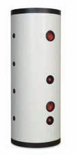
51 INUSTIAS POUCT ANGE The A-A buffer storage tanks are designed to store cooling water to supply air conditioning and heat pump systems respectively. The aim is to ensure a steady temperature reducing the starting and stopping operations of the cooling or boiling systems when there are rapid temperature variations. There is no any anti-corrosion internal treatment (No internal coating) bear in mind the A series tanks are used in closed circuit without any adding air. The A-A are manufactured by Industrias Ibaiondo S.A. according to the required procedures and certified staff and in strict compliance with the 97/23/EC irective. Outside thermal insulation consisting of polyurethane rigid foam direct injection (CFC free), with a minimum thickness of 50 mm in tanks up to Liters and polyethylene linner of 19 mm thickness from Liters up to Liters. Standard external finish with aluminium lining from 30 Liters up to 1500 Liters and detachable grey PVC jacket from liters up to Liters and top cover. All sleeves are protected with trims and caps. The inlet fittings arrangement and design favors the hot water stratification and a correct energetic efficiency Temperature: +60ºC. imum pressure: 6 Bar. esigned and manufactured according to irective 97/23/EC (art 3.3). Centr al FCooling r igorí funit ica Para ver esta pel cula, debe Para ver esta pel cula, debe disponer de QuickTimeª y de disponer de QuickTimeª de un descompresor. un descompresor. Caldera Boiler unit Para ver esta pel cula, debe Para ver esta pel cula, debe disponer de QuickTimeª y de disponer de QuickTimeª de un descompresor. un descompresor. Buffer - Cooling system Buffer-boiler system 50


52 A - A SEIES Cold water tanks (cooling systems and heating pumps) INUSTIAS Tanks with polyurethane rigid foam and aluminium lining 6 Bar Connection e - r t - s p - v A-A / 2 1 / A-A / 2 1 / A-A / 4 1 / / A-A / 2 1 / / A-A / / A-A / / A-A / / A-A / / A-A / / 4 Tanks with polyethylene lining and PVC jacket 6 Bar Connection e - r t - s p - v A-A / / A-A / / A-A / / A-A / / 4 NOTE: Optionally available with outdoor coating A-A A-A 51


53 INUSTIAS POUCT ANGE PF/PF Buffer tanks are specifically designed for the production and storage of heating hot water in centralized storage solar systems when large scale storage of heating water is required. PF/PF Buffer tanks are connected to the heating system to store hot water produced from the solar panels in primary circuit. ue to the lack of inner protection, they can never be used in hot sanitary and drinking supply systems. PF/ PF Buffer tanks are widely used in current solar systems due to the high performance and the reduction of the space required for their installation. The use with a sanitary water tanks avoids legionella. PF version incorporates carbon steel fixed heat exchanger of high capacity. There is no any anti-corrosion internal treatment (No internal coating) bear in mind the PF/PF series buffer tanks are used in closed circuit without any adding air. Outside thermal insulation consisting of polyurethane rigid foam direct injection (CFC free), with a minimum thickness of 50 mm in tanks up to Liters and flexible polyurethane 80 mm thickness from Liters up to Liters. Standard external finish with detachable grey PVC jacket and top cover. All sleeves are protected with trims and caps. The inlet fittings arrangement and design favors the hot water stratification and a correct energetic efficiency Temperature: +100ºC. imum pressure: 6 Bar. esigned and manufactured according to directive 97/23/EC (art 3.3). 52
54 PF / PF SEIES Solar buffer tanks INUSTIAS Buffer storage tanks PF 6 Bar Connection e - r t - s p - v PF ¼ 1 / / PF ½ 1 / / PF / / PF / / PF / / PF / / PF / / Connection e - r t - s p - v PF / / PF / / PF / / PF / / 4 Buffer tanks with heat exchanger PF 6 Bar Exchanger Surface m PF , PF PF PF PF , PF / PF 2000 / 5000 PF PF 53
 must be connected with the heating system (primary circuit).")
55 INUSTIAS POUCT ANGE ACES-ACET series are specifically designed for double use, the production and storage of hot water (heating) and hot sanitary water in combined systems. ACET series, commonly known as tank in tank, are made of two tanks, one inside the other. The carbon steel buffer (External tank) must be connected with the heating system (primary circuit). ue to the lack of inner protection, they can never be connect in hot sanitary and drinking supply systems directly. The inside replaceable sanitary tank (SW) is made of stainless steel AISI 316 L. ACES series are made of an external tank which joins inside one coil. The carbon steel buffer (External tank) must be connected with the heating system (primary circuit). ue to the lack of inner protection, they can never be connect in hot sanitary and drinking supply systems directly. The inside replaceable corrugate stainless steel coil is made (SW) of stainless steel AISI 316 L. ACET-ACES series offer the possibility of adding one or two fixed heat exchangers, giving the possibility to connect them to boilers or solar systems Guarantee: 5 years ACET series (ACET-0, ACET-1, ACET-2): Buffer tank (External tank): Black steel according to directive 97/23/EC. No internal treatment. Upper flange N / temperature max (Buffer): 6 bar / 100ºC.. / temperature max (Exchanger): 10 bar / 100ºC. Stainless Steel tank characteristics, SW: Stainless steel replaceable tank (AISI 316L).. / temperature max: 10 bar / 95ºC. ACET-1 & ACET-2: Incorporates one or two carbon steel fixed heat exchanger. er. ACES series (ACES-0, ACES-1, ACET-2): Buffer tank (External tank): Black steel according to directive 97/23/EC. No internal treatment. Upper flange N / temperature (Buffer): 6 bar / 100ºC.. / temperature (Exchanger): 10 bar / 100ºC Stainless steel Coil characteristics, SW: Stainless steel replaceable coil (AISI 316 L).. / temperature max: 10 bar / 95ºC. Every model is supplied with a detachable flexible polyurethane foam (100 mm thinckness) and grey detachable PVC finish jacket. ACES-1 & ACES-2: Incorporates one or two carbon steel fixed heat exchanger. er.. 54


56 ACET SEIES ot sanitary water buffer INUSTIAS Buffer tanks without exchanger ACET Lower Exchanger Surface (m 2 ) Upper Exchanger Surface (m 2 ) ACET ACET ACET ACET ACET Buffer tanks with one exchanger ACET Lower Exchanger Surface (m 2 ) Upper Exchanger Surface (m 2 ) ACET ACET , ACET , ACET , ACET ,3 -- Buffer tanks with two exchanger ACET Lower Exchanger Surface (m 2 ) Upper Exchanger Surface (m 2 ) ACET , ACET ,5 1, ACET , ACET ,2 2, ACET ,3 2,1 55
 16950000 500 ACES-0 500 6 700 1950 3,8 -- -- 16975000 750 ACES-0 750 6 950 1850 3,8 -- -- 16910000 1000 ACES-0 1000 6 950 2320 5 -- -- 16912500 1250 ACES-0 1250 6 1160 2050 5 -- --")

57 INUSTIAS ACES SEIES BUFFE ACS (ot sanitary and solar systems) Buffer tanks without exchanger ACES SW Exchanger Surface (m 2 ) Lower Exchanger Surface (m 2 ) Upper Exchanger Surface (m 2 ) ACES , ACES , ACES ACES ACES , Buffer tanks with one exchanger ACES SW Exchanger Surface (m 2 ) Lower Exchanger Surface (m 2 ) Upper Exchanger Surface (m 2 ) ACES , ACES ,8 2, ACES , ACES , ACES ,3 4,3 -- Buffer tanks with two exchanger ACES SW Exchanger Surface (m 2 ) Lower Exchanger Surface (m 2 ) Upper Exchanger Surface (m 2 ) ACES ,8 2 1, ACES ,8 2,5 1, ACES , ACES ,2 2, ACES ,3 4,3 2,1 56

58 SEIE C Compressed air tanks INUSTIAS - Tank made of steel S-275-J - esigned for the storage and distribution of compressed air - External finish: red primer coating - esigned and manufactured according to 97/23/EC or 87/404/EC Vertical Tanks 10 Bar Connection a - u v - s m - p lc / / 2 1 / lc / / 2 1 / lc / / 2 1 / lc / / 2 1 / C / / 2 1 / C / / 2 1 / C / / 2 1 / C / 2 1 / C / 2 1 / C / 2 1 / 2-3 / 4 Vertical Tanks 15 Bar Connection a - u v - s m - p lc / / 2 1 / lc / / 2 1 / C / / 2 1 / C / / 2 1 / C / / 2 1 / C / / 2 1 / C / 2 1 / C / 2 1 / C / 2 1 / 2-3 / 4 57


59 INUSTIAS SPAE PATS Covers Accessories A-A / PF 460 Cover A-A / PF / PF 650 Cover A-A / PF / PF 700 Cover A-A / PF 910 Cover A-A / PF / PF 950 Cover A-A / PF / PF 1160 Cover A-A / PF / PF 1360 Cover A-A / PF 1660 Cover A-A / PF 1960 Cover Embellisher Accessories Connection A-A / PF / PF Embellisher 1 / A-A / PF / PF Embellisher 1 1 / A-A / PF / PF Embellisher A-A / PF / PF Embellisher A-A / PF / PF Embellisher Ø A-A / PF / PF Embellisher Ø A-A / PF Embellisher 1 1 / 4 58
60 ACCESOIES & SPAE PATS Orange PVC jacket with zipper INUSTIAS Accessories A-A / PF / PF Orange jacket A-A / PF / PF Orange jacket A-A / PF / PF Orange jacket A-A / PF / PF Orange jacket A-A / PF / PF Orange jacket Grey PVC jacket with zipper Accessories PF Grey jacket PF Grey jacket PF / PF Grey jacket PF / PF Grey jacket PF / PF Grey jacket PF / PF Grey jacket Outside grey jacket Accessories A - A / PF / PF Outside jacket A - A / PF / PF Outside jacket A - A / PF / PF Outside jacket A - A / PF / PF Outside jacket A - A / PF / PF Outside jacket Grey jacket (flexible foam) PF Ø 1260 X PF Ø 1460 X PF Ø 1560 X PF Ø 1760 X 3000 Orange jacket for polyethylene insulation Accessories A - A AJUSTABLE A - A AJUSTABLE A - A AJUSTABLE A - A AJUSTABLE 59
61 INUSTIAS GENEAL SALES CONITIONS (2 years guarantee) 1.-INTOUCTION The current Sales Conditions will be applied to every offer and sale of products in which IBAIONO takes part as vendor. The conditions suggested by the Purchaser in the order or in any other document will be only included in the contract when they had been clearly accepted in writing by IBAIONO. 2.- CATALOGUES All the data, measurements, technical details, photographs and so on provided in our catalogues and website, are only for guidance and they are liable to modifications without notice. The reference of this information will have to be expressly shown in the offer or contract to be binding. 3.- OFFES Save any specifi cation in the offers, their validity is for 30 days from the date of issue. Without prejudice to the aforementioned, Industrias IBAIONO can cancel his offers at any time before having received the approval of the purchaser. The current valid VAT will be applied to every price. 4.- OES The orders will be preferably placed by fax, or through our website. They will have to mention exactly the code reference number of the requested product and the delivery address. IBAIONO will not assume the responsibility for the possible faulty identification of the orders. It is compulsory to receive the Order Confirmation Sheet ( C- 458) duly signed by the Client to deal with the manufacture of the products made on request. Ibaiondo reserves the right to accept any order within a period of 30 days from its reception. 5.- ELIVEY The agreed delivery date means the scheduled date of goods shipment from IBAIONO. The delivery time will always be approximate. Ibaiondo is entitled to make partial deliveries. If there is not any delivery date agreement, it will be carried out according to the manufacturing capacity of IBAIONO. If there was a delay of more than three months from the scheduled delivery time, the Purchaser is entitled to cancel the order in writing by early warning to IBAIONO with no possibility of compensation in damages by way of delay or NON ELIVEY. 6.- SIGNIFICANCE OF TE SUPPLYING The following matters are responsibility of IBAIONO: The offered product and the technical documentation legally required or the documents decided by both parts. The following matters are responsibility of the purchaser: The transport of the goods, unless it was indicated in the offer otherwise. The installation and Starting unless it was indicated in the offer otherwise. Cranes and necessary means for unloading the supplied merchandise. Free access of the truck which carries the product to the Installation place. Installation Civil Works In general, everything which is not expressly and particularly included in the offer. 7.- TANSPOT AN TANSFE OF TE ISK Unless something else had been agreed, it is understood that the sale is carried out EX-WOKS terms from IBAIONO Warehouse. The risk of loss or damage of the material as well as the risks related to the storage and use of the goods, are transferred to the Purchaser at the delivery time. The goods are carried accordingly at Addressee s own risk regardless of the transport terms: Carriage paid or fr eight forward. The Buyer must make sure of the delivery approval and the right conditions of the products before assuming the delivery and unloading of the merchandise. In case of being a loss, breaking or damage of some of the products, the Purchaser will have to request to the carrier the examination of the merchandise and to have that minuted. If the items show a noticeable fault of quantity or quality at a glance, the Purchaser will have to notify it to IBAIONO in writing within a period of FIVE days from the delivery date. If the damages are not visually obvious, the provided on the paragraph of GUAANTEE will be applied. 8.- SAFETY IBAIONO products, with regards to the manufacturing and design, fulfil all the safety requirements for pressure vessels specified in the Guidelines: 97/23/CE 0-87/404/CE. 9.- GUAANTEE All IBAIONO products will be replaced or repaired free of charge in case of manufacturing faults within the guarantee period arranged in the offer, or failing him, in the catalogues in force. The following cases are not under guarantee: The bad or wrong use of a product, the inappropriate handling, when the maximum pressure or temperature have been exceeded or in general when any of the starting, use or maintenance instruction included in the provided documents, had not been respected. IBAIONO is not responsible for the direct or indirect damages caused by fault or defect of their products and of any other claim resulted from these reasons unless the law provides compulsory the contrary. When the requested instructions had been followed, IBAIONO will opt for repairing the fault and defect of the products for delivering new items free of charge. IBAIONO will also be empowered to pay the total value of the faulty products or the lacks of them to the Purchaser. The faulty items will be sent back at the request of IBAIONO before carrying out the delivery of the new product AFTE SALES SEVICE The Purchaser must cooperate with the Technical adviser department of IBAIONO for the right defi nition of the failure in order to analyse previously the necessity of a technical supervision in situ before displacing the maintenance engineers. The maintenance costs caused by the supervision of products under guarantee or the starting confi rmed by contract will be on Purchaser s own account on the assumption that the technicians had already been displaced with no possibility to perform their duties due to reasons attributed to the Purchaser 11.- PAYMENT The fi xed terms of payment will not be interrupted in case the starting or the shipment of the products should not carry out within the scheduled delivery time, due to reasons not attributed to IBAIONO. In this case, the invoices and bank giros will be consequently issued from the notification date of availability of the products ready for shipment. The maintenance and storage costs caused from the notifi ation date will also be on Customer s own account. The non-payment when the bills or invoices become mature implies the immediate interruption of the supplies and services OMINIUM ESEVE IBAIONO reserves the right of property of the supplied products till the wholly price had been paid by the Purchaser. IBAIONO will have the right to recover the possession of the products even entering the property or the building where they were located. 60

62 INUSTIAS POUCT GUIE Plentzia Bidea, 3 (Billela Auzotegia) MUNGIA Apartado 21 Bizkaia SPAIN Tel.: Fax: exportacion@ibaiondo.com exportec@ibaiondo.com SEPTEMBE 2014
INDUSTRIAS IBAIONDO, HYDROPNEUMATIC TANKS
 IBAIONDO, HYDROPNEUMATIC TANKS IBAIONDO, INTRODUCTION Hydropneumatic tanks are designed to be used in potable water supply installations as a part of the pressure booster set in order to ensure the adequate
Airfix Pressure expansion vessels for sanitary appliances and potable water systems
 airfix expansion vessels Your reliable partner 4 Airfix Pressure expansion vessels for sanitary appliances and potable water systems AIRFIX A AIRFIX AIRFIX -E AIRFIX P Edition EXP 2009 Flamco offers you
NITROGEN CHARGING KIT type PC 11.1 E 04-11
 NITROGEN CHARGING KIT type PC 11.1 E 04-11 11.1.1 TECHNICAL DATA MAX OPERATING PRESSURE (PS): 600 BAR PRESSURE TEST (PT): 1.43 PS SCALE OF PRESSURE GAUGE: 4-10 - 16-25 - 60-100 - 250 (std.) - 400-600 bar
NITROGEN CHARGING KIT type PC 11.1 E 01-12
 NITROGEN CHARGING KIT type PC 11.1 E 01-12 11.1.1 TECHNICAL DATA MAX OPERATING PRESSURE (PS): 600 BAR PRESSURE TEST (PT): 1.43 PS SCALE OF PRESSURE GAUGE: 4-10 - 16-25 - 60-100 - 250 (std.) - 400-600 bar
Airfix D-E-B Installation and operating instructions
 www.flamco.nt-rt.ru Airfix D-E-B Installation and operating instructions Dear Customer, With the Airfix D-E-B membrane expansion vessel you have acquired a Flamco quality product. This expansion vessel
Expansion Vessels for Potable Installations
 4. Expansion Vessels for Potable Installations Domestic installations lose millions of litres of potable water due to expansion water leaking from the vent and expansion pipe. Flamco s Airfix diaphragm
CAST IRON SAFETY VALVE TYPE 6301
 CHARACTERISTICS The 6301 safety valve is dedicated to protect the equipment from potential overpressure. This is an automatic device that closes when the pressure conditions are back to normal. It is a
Unit 24: Applications of Pneumatics and Hydraulics
 Unit 24: Applications of Pneumatics and Hydraulics Unit code: J/601/1496 QCF level: 4 Credit value: 15 OUTCOME 2 TUTORIAL 9 ACCUMULATORS The material needed for outcome 2 is very extensive so there are
VESSELS. DIAPHRAGM OR BLADDER TANKS For expansion and pressure boosting applications. Temperature range : -10 to C* Operating pressure :
 operating limits Temperature range : -10 to + C* Operating pressure : to 20 bar* * according to models. VESSES IAPHRAGM OR BAER TANKS For expansion and pressure boosting applications AdVANTAGES APPICATIONS
Application and Sizing
 Application and Sizing Energy accumulator: It is improbable that an hydraulic system use all of its capacity without interruptions. An hydropneumatic accumulator can store a certain amount of fluid that
Diaphragm Accumulators
 Diaphragm Accumulators HYDAC Diaphragm Accumulators Index Page 1. Description 3 Introduction 3 Construction 3 2. Applications 4 3. Technical Data 6 Operation 6 Technical Specifications 6 Temperature Effect
G type DUCTED EXHAUST SAFETY VALVE 2871 AND 288X SERIES. Model/Ref:
 Model/Ref: 28713 www.lauridsenindustri.com CHARACTERISTICS The G type safety valves are dedicated to protect the equipment from potential overpressure. They are automatic and close when the pressure conditions
Airfix. Flamco. Flamco. Pressure expansion vessels for sanitary appliances and potable water systems AIRFIX A AIRFIX D AIRFIX D-E
 AIRFIX EXPANSION VESSELS Flamco Airfix Pressure expansion vessels for sanitary appliances and potable water systems AIRFIX A AIRFIX AIRFIX -E Flamco Edition 2005 / EXP Flamco Flamco offers you a wide choice
FLUID POWER FLUID POWER EQUIPMENT TUTORIAL ACCUMULATORS. This work covers part of outcome 2 of the Edexcel standard module:
 FLUID POWER FLUID POWER EQUIPMENT TUTORIAL ACCUMULATORS This work covers part of outcome 2 of the Edexcel standard module: UNIT 21746P APPLIED PNEUMATICS AND HYDRAULICS The material needed for outcome
Model MTB-ASME Vertical Bladder Tanks
 DATA SHEET Model MTB-ASME Vertical Bladder Tanks Features n UL Listed for use with various proportioners and foam concentrates n 175 psi (12.1 bar) maximum allowable working pressure (design pressure)
Model MTB-ASME Vertical Bladder Tanks
 DATA SHEET Model MTB-ASME Vertical Bladder Tanks Features n UL Listed for use with various proportioners and foam concentrates n 175 psi (12.1 bar) maximum allowable working pressure (design pressure)
Horizontal Bladder Tanks
 DATA SHEET Horizontal Bladder Tanks Features UL Listed and FM Approved for use with various ANSUL proportioners and foam concentrates 175 psi (12.1 bar) maximum allowable working pressure (design pressure)
Vertical Bladder Tanks
 DATA SHEET Vertical Bladder Tanks Features UL Listed and FM Approved for use with various ANSUL proportioners and foam concentrates 175 psi (12.1 bar) maximum allowable working pressure (design pressure)
Measurement accessories METPOINT OCV for the measurement in systems up to 40 bar
 EN - english Instructions for installation and operation Measurement accessories METPOINT OCV for the measurement in systems up to 40 bar Dear customer, Thank you for deciding in favour of the METPOINT
Model MTB-ASME Horizontal Bladder Tanks
 DATA SHEET Model MTB-ASME Horizontal Bladder Tanks Features n UL Listed and FM Approved for use with various proportioners and foam concentrates n 175 psi (12.1 bar) maximum allowable working pressure
AUTOMATIC HOSE TEST UNIT, TYPE SPU
 VALVES AND FITTINGS UP TO 14,000 BAR TEST AND CONTROL EQUIPMENT H IGH PRESSURE TECHNOLOGY AUTOMATIC HOSE TEST UNIT, TYPE SPU Pressure range from 1 up to 10,000 bar User-friendly touch panel operation HIGH-PRESSURE
ANNEX AMENDMENTS TO THE INTERNATIONAL CODE FOR FIRE SAFETY SYSTEMS (FSS CODE) CHAPTER 15 INERT GAS SYSTEMS
 CHAPTER 15 INERT GAS SYSTEMS") Annex 3, page 2 ANNEX AMENDMENTS TO THE INTERNATIONAL CODE FOR FIRE SAFETY SYSTEMS (FSS CODE) CHAPTER 15 INERT GAS SYSTEMS The text of existing chapter 15 is replaced by the following: "1 Application This
Annex 3, page 2 ANNEX AMENDMENTS TO THE INTERNATIONAL CODE FOR FIRE SAFETY SYSTEMS (FSS CODE) CHAPTER 15 INERT GAS SYSTEMS The text of existing chapter 15 is replaced by the following: "1 Application This
Assembly-, installation- and maintenance instruction manual for bladder accumulators IBV / EBV , top reparable
 Page 1 von 8 Assembly-, installation- and maintenance instruction manual for bladder accumulators IBV / EBV 100-575, top reparable Content Seite 0 Legend 2 1 Overview 2 2 Accumulator assembly and installation
TECHNICAL DATA. Trimpac 257a. September 16, 2013
 September 16, 2013 Trimpac 257a 1. DESCrIpTION DESCRIPTION The Viking Double SUREFIRE SIngle Interlock Preaction TRIMPAC Model D-2 and D-2B used with either a Model E or F Deluge Valve (A.1), a Viking
HydroCOM: High energy savings and excellent controllability
 HydroCOM: High energy savings and excellent controllability Almost all applications require efficient capacity control systems Most of them simply waste energy, are slow and inaccurate. HydroCOM, however,
Medium-sized vessels water connection. White paper
 Medium-sized vessels water connection White paper Flamco B.V. January 2017 Medium-sized vessels water connection In practice you will find expansion vessels with the water connection on bottom, and with
Materials : Dichromate zinc plated steel flanges or AISI 316
 Size : Ends : Min Temperature : Max Temperature : DN 25 to 300 Flanges PN10/16-35 C + 90 C Max Pressure : 16 Bars (10 bars at 90 C) Specifications : Absorb vibrations and noise Linear and angular compansion
Materials : Dichromate zinc plated steel flanges
 Size : Ends : Min Temperature : Max Temperature : DN 25 to 300 Flanges PN10/16-35 C + 130 C Max Pressure : 16 Bars up to DN150, 10 bars over Specifications : Absorb vibrations and noise Linear and angular
GUKO FDA. einfach. gut. beraten.
 GUKO FDA Size : Ends : Min Temperature : Max Temperature : DN 25 to 300 Flanges PN10/16-25 C + 90 C Max Pressure : 16 Bars Specifications : Absorb vibrations and noise Linear and angular compansion Inner
TP1 and TP2 Temporary Cone Shaped Strainers
 1698051/2 IM-P169-07 ST Issue 2 TP1 and TP2 Temporary Cone Shaped Strainers Installation and Maintenance Instructions TP1 1. Safety information 2. General product information 3. Installation and commissioning
MANUALLY OPERATED VALVE VLM SYNCROFLUX TECHNICAL MANUAL MT042/E
 MANUALLY OPERATED VALVE VLM SYNCROFLUX TECHNICAL MANUAL MT042/E INSTALLATION, COMMISSIONING AND MAINTENANCE INSTRUCTIONS CONTENTS 1.0 INTRODUCTION 1.1 MAIN CHARACTERISTICS 1.2 VALVE CONTROL 2.0 INSTALLATION
KBV21i and KBV40i Key Operated Boiler Blowdown Valves Installation and Maintenance Instructions
 4059051/3 IM-P405-48 EMM Issue 3 KBV21i and KBV40i Key Operated Boiler Blowdown Valves Installation and Maintenance Instructions 1. Safety information 2. General product information 3. Installation 4.
Serie ECO 3F. Flanged back flow preventer with controllable reduced pressure zone. made in. Application fields. Protection
 Flanged back flow preventer with controllable reduced pressure zone made in Application fields WATER FIRE FIGHTING DRINKING WATER 64 www.brandoni.it The ECO 3F flanged backflow preventers, which have a
Materials : Galvanized steel flanges
 Size : Ends : Min Temperature : Max Temperature : DN 32 to 200 Flanges PN10/16-10 C + 80 C Max Pressure : 16 Bars Specifications : Absorb vibrations and noises Linear and angular compansion Single NBR
TECHNICAL DATA. Trimpac 256a. October 31, 2013
 October 31, 2013 Trimpac 256a 1. DESCRIPTION The Viking SUREFIRE SIngle Interlock Preaction TRIMPAC Model D-1 and D- 1B used with either a Model E or F Deluge Valve (A.1), a Viking Easy Riser check valve
Installation, Operation and Maintenance Instructions Buffer Vessel OM006
 Installation, Operation and Maintenance Instructions Buffer Vessel OM006 Calorifiers Heat Exchangers Pressurisation Units Sales Tel: 01457 835700 Sales Fax: 01457 832700 E-mail: sales@gmsthermal.co.uk
C Lite CAD SERIES. ACS Approved. Patented CAD-2 diaphragm technology. Rugged copolymer polypropylene base. Quality brass air stem with o-ring seal
 2 C Lite CAD SERIES Patented CAD-2 diaphragm technology Unique 3 piece construction Reinforced Plastic Connection Durable continuous strand fiberglass sealed with epoxy resin NSF Standard 61, CE/PED, WRAS,
776 Cryogenic Safety Valve
 776 Cryogenic Safety Valve INTRODUCTION 776 Cryogenic Safety Valve The effects of exceeding safe pressure levels in an unprotected pressure vessel or system, can have catastrophic effects on both plant
Serie ECO 3T. Threaded end back flow preventer with controllable reduced pressure zone. made in. Application fields. Protection E U R O P E
 Serie ECO T Threaded end back flow preventer with controllable reduced pressure zone BRANDONI made in E U R O P E Application fields WATER FIRE FIGHTING DRINKING WATER 74 www.brandoni.it Serie ECO T The
6301 TYPE CAST IRON SAFETY VALVES
 Pressure (bar) 6301 TYPE CAST IRON SAFETY VALVES FEATURES The 6301 type safety valve is a device designed to protect installations against possible overpressure. It operates automatically and closes when
TECHNICAL DATA. TRIMPAC Model B-5 & B-5B
 September 16, 2013 Trimpac 250a 1. DESCRIPTION DEsCRIPTIoN is a factory assembled trim package for a ed an electric/pneumatic release module in a metal enclosure. The standard trim normally required on
DN 50 REGULATOR SUTON 5000A1 REGULATOR SUTON 5000D1
 www.apq.com.es EU Product / Spain DN 50 REGULATOR SUTON 5000A1 REGULATOR SUTON 5000D1 Cod. RISUT5000A1 Cod. RISUT5000D1 DESCRIPTION The Suton 50001 Regulator is designed for use in distribution networks
Manual Actuated Boiler Blowdown Valves
 Manual Actuated Boiler Blowdown Valves Installation and Maintenance Instructions 1. Safety information 2. General product information 3. Installation 4. Operation 5. Maintenance 6. Spare parts p.1 1. Safety
IX1 Spirax-Monnier International Compressed Air Filter Installation and Maintenance Instructions
 0575050/2 IM-P057-04 CH Issue 2 IX1 Spirax-Monnier International Compressed Air Filter Installation and Maintenance Instructions 1 Safety information 2 General product information 3 Installation and commissioning
Installation, Operating and Maintenance Manual Overflow Regulator Type 94/ 94 E
 Installation, Operating and Maintenance Manual Overflow Regulator Type 94/ 94 E Table of content 1. General information on installation, operating and maintenance instructions 1.1 Hazard notices 1.2 Qualified
Materials : Electro galvanized steel flanges
 Size : Ends : Min Temperature : Max Temperature : DN 32 to 600 Flanges PN10/16-10 C + 100 C for EPDM and + 80 C for NBR Max Pressure : 16 Bars up to DN 300 Specifications : Absorb vibrations and noises
BT6HC Hygienic Sanitary Balanced Pressure Steam Trap for High Capacity and CIP/SIP Applications
 1800350/6 IM-P180-12 ST Issue 6 BT6HC Hygienic Sanitary Balanced Pressure Steam Trap for High Capacity and CIP/SIP Applications Installation and Maintenance Instructions 1. Safety information 2. General
KBV21i and KBV40i Air Actuated Boiler Blowdown Valves
 4059051/1 IM-P405-48 AB Issue 1 KBV21i and KBV40i Air Actuated Boiler Blowdown Valves Installation and Maintenance Instructions 1. Safety information 2. General product information 3. Installation 4. Commissioning
TECHNICAL DATA. Trimpac 251a. Spetember 16, 2013
 Spetember 16, 2013 Trimpac 251a 1. DEsCrIpTION DESCRIPTION TRIMPAC Model B-6 and B-6B is a factory assembled trim package for a double interlocked preaction system with an electric/pneu-lectric release
Spiratec ST14, ST16 and ST17 Sensor Chambers and sensors
 0862050/1 IM-P086-18 MI Issue 1 Spiratec ST14, ST16 and ST17 Sensor Chambers and sensors Installation and Maintenance Instructions 1. Safety Information 2. General product information 3. Installation 4.
Pilot Check Valve: Metal Body Type
 INFORMATION Pilot Check Valve: Metal Body Type The use of a metal body improves strength and environmental resistance. Temporary intermediate stops are possible. *1 *1 Precise intermediate stops are not
TECHNICAL DATA MAINTENANCE AIR COMPRESSOR MODEL G-1
 Dry 131h 1. DESCRIPTION The Viking Model G-1 Maintenance Air Compressor is an electric motor-driven, aircooled, single-stage, oil-less compressor. The unit is equipped with a check valve and provides a
VERTICAL BLADDER TANK
 Balanced Pressure Proportioning System Reliable Foam System Requiring Only Water Power Perfect For Tight Spaces UL Listed, ASME, National Board Registered Bladder-UL162 Approved, High Tensile Pressure
Instruction Manual. CG16K Barometrically Compensated Capsule Dial Gauge. CG16K Capsule Dial Gauge, 0 to 25 mbar
 Instruction Manual D356-10-880 Issue G Original CG16K Barometrically Compensated Capsule Dial Gauge Description CG16K Capsule Dial Gauge, 0 to 1040 mbar CG16K Capsule Dial Gauge, 0 to 125 mbar CG16K Capsule
tubepress press procedure
 tubepress press procedure tubepress 15mm up to 35mm tubepress 15 mm up to 35 mm 1. The tube ends must be clean with no scratches or grooves. Remove end caps. Cut tube to length. 2. Deburr tube inside and
MANUAL. Sesame. Thermoplastic Tank Technologies
 MANUAL Sesame Thermoplastic Tank Technologies INSTALLATION AND USER GUIDE CONTENT 1. GENERAL 3 2. IMPORTANT 3 3. INSTALLATION EXPANSION VESSEL 4 4. USE EXPANSION VESSEL 5 5. AIR CELL REPLACEMENT 5 5.1
System Pressure Manager Standard & System Pressure Manager Plus
 System Pressure Manager Standard & System Pressure Manager Plus Installation, Commissioning & Servicing Instructions Note: THESE INSTRUCTIONS MUST BE READ AND UNDERSTOOD BEFORE INSTALLING, COMMISSIONING,
TECHNICAL DATA. Trimpac 244a. September 16, 2013
 September 16, 2013 Trimpac 244a 1. DEsCrIpTION DESCRIPTION TRIMPAC Model B-1 and B-1B is a factory-assembled trim package with an electric release module in a metal enclosure. The standard trim normally
TECHNICAL DATA. Q = C v P S
 January 6, 2012 Preaction 348a 1. Description Viking supervised Surefire Preaction Systems utilize the Viking G-6000P Valve. The small profile, lightweight, pilot operated Viking G-6000P Valve comes complete
TECHNICAL DATA. Q = C v P S
 Preaction 346a 1. Description The 6 Model G-6000P Electric Release Preaction System Riser Assembly can be used as a Single Interlock Preaction System with Electric Release, or as a Double Interlock Preaction
Components for air preparation and pressure adjustment. OUT port position ( ) connected Rear side. of IN port. Air tank. directly.
 connected Rear side. of IN port. Air tank. directly.") Components preparation and pressure adjustment ABP Overview ABP is a component that enables boosting by s only up to twice primary pressure (.0MPa max.) in combination with using air tank but not using
Components preparation and pressure adjustment ABP Overview ABP is a component that enables boosting by s only up to twice primary pressure (.0MPa max.) in combination with using air tank but not using
CVS10 Sanitary Check Valves
 0299050/4 IM-P029-11 ST Issue 4 CVS10 Sanitary Check Valves Installation and Maintenance Instructions 1. Safety information CVS10 with soft seat 2. General product information 3. Operation 4. Installation
FV Flash Vessel Installation and Maintenance Instructions
 4041050/5 IM-P404-10 EMM Issue 5 FV Flash Vessel Installation and Maintenance Instructions 1. Safety information 2. Specific product safety information 3. Product information 4. Installation 5. Commissioning
GUMMIKOMPENSATOR GKF8000 / GKF8130
 GUMMIKOMPENSATOR GKF8000 / GKF8 Size : Ends : Min Temperature : Max Temperature : DN 32 to 600 Flanges PN10/16-10 C + 100 C for EPDM and + 80 C for NBR Max Pressure : 16 Bars up to DN 300 Specifications
TECHNICAL DATA SINGLE INTERLOCKED PREACTION SYSTEM WITH PNEUMATIC RELEASE
 1 of 10 1. DESCRIPTION (Refer to Figures 1-3.) Viking supervised Single Interlocked Preaction Systems utilize a Viking Deluge Valve and a pneumatically pressurized automatic sprinkler system. The system
Accessories for Sanitary Installations
 5. Accessories for Sanitary Installations Flamco s Prescor B safety valves protect potable water systems from exceeding the maximum design operating pressure. Once the set pressure has been reached the
TECHNICAL DATA. Q = C v P S
 January 6, 2012 Preaction 333a 1. Description Viking supervised Surefire Preaction Systems Utilize the Viking G-3000P Valve. The small profile, lightweight, pilot-operated Viking G-3000P Valve comes complete
Flamco Airfix D-E. Installation and operating instructions. 1999, Flamco eps
 Airfix D-E 6442.eps GB Installation and operating instructions 1999, Exclusion of liability All operation and maintenance related technical information, data and instructions contained in these installation
PRESSURE REGULATOR LBM SERIES
 VIRTUAL CATALOGUE FAIL TO OPEN REGULATOR HIGH FLOW COEFFICIENT WIDE PRESSURE-REGULATION RANGE FAST RESPONSE PRESSURE REGULATOR LBM SERIES FULL SEAL AT ZERO FLOW CAN BE SUPPLIED WITH MINIMUM / MAXIMUM PRESSURE
Size : Ends : Min Temperature : Max Temperature : Materials : Cast iron body
 Size : Ends : Min Temperature : Max Temperature : DN 40 to DN 300 Flanges R.F. PN10/16-10 C + 80 C Max Pressure : 16 Bars up to DN200 Specifications : Removable stainless steel filter Bolted bonnet with
Operating Manual FSV, FSÖV, SSVF
 Contents 1. General Remarks... 1 1.1. Marking... 2 1.2. Tightness of the Quick-Closing Valve... 2 1.3. Medium... 2 1.4. Ambient and Medium Temperature... 3 1.5. Vibrations... 3 1.6. Pipe Tensions... 3
Size : Ends : Min Temperature : Max Temperature : Materials : Galvanized steel flanges
 Size : Ends : Min Temperature : Max Temperature : DN 32 to 600 Flanges ISO PN10/16-10 C + 100 C for EPDM and + 80 C for NBR Max Pressure : 16 Bars up to DN 300 Specifications : Absorb vibrations and noises
MST21 Stainless Steel Balanced Pressure Thermostatic Steam Trap
 1250650/6 IM-P125-07 ST Issue 6 MST21 Stainless Steel Balanced Pressure Thermostatic Steam Trap Installation and Maintenance Instructions 1. Safety information 2. General product information 3. Installation
Installation Operation Maintenance
 682 Seal Cooler New generation seal cooler to meet and exceed the seal cooler requirements stated in the 4th Edition of API Standard 682 Installation Operation Maintenance Experience In Motion Description
Differential Pressure Regulator Type Type 45-6 (0.1 to 1 bar, DN 15) Mounting and Operating Instructions EB 3226 EN
 Mounting and Operating Instructions EB 3226 EN") Differential Pressure Regulator Type 45-6 Type 45-6 (0.1 to 1 bar, DN 15) Mounting and Operating Instructions EB 3226 EN Edition March 2008 Contents Contents Page 1 Design and principle of operation...................
Differential Pressure Regulator Type 45-6 Type 45-6 (0.1 to 1 bar, DN 15) Mounting and Operating Instructions EB 3226 EN Edition March 2008 Contents Contents Page 1 Design and principle of operation...................
DCV1, DCV3 and DCV3LT Disc Check Valves Installation and Maintenance Instructions
 1340050/7 IM-P134-07 CMGT Issue 7 DCV1, DCV3 and DCV3LT Disc Check Valves Installation and Maintenance Instructions 1. Safety information 2. General product information 3. Installation 4. Commissioning
BIMBAR INFLATABLE PACKERS AND ACCESSORIES
 BIMBAR INFLATABLE PACKERS AND ACCESSORIES Geopro supplies a complete range of inflatable packers in nine different diameters from 28 up to 170mm. All our packers made of BIMBAR rubber technology are reinforced
VALFONTA INSTRUCTIONS: OPERATION AND INSTALLATION PRESSURE REDUCING VALVE MODEL PRV44
 INSTRUCTIONS: OPERATION AND INSTALLATION PRESSURE REDUCING VALVE MODEL PRV44 Pressure Reducing Valve PRV44 - Operation and Installation - 1 - manual PRV44-16-ENG JULY 2016 INDEX PAGE 1 IDENTIFICATION PLATE
OPERATION MANUAL NTF-15
 OPERATION MANUAL NTF-15 Nitrogen Tire Filling Valve Stem Caps (Qty=200) Order P/N 436075 RTI Technologies, Inc 10 Innovation Drive York, PA 17402 800-468-2321 www.rtitech.com 035-81235-00 (Rev B) TABLE
AVM7 Stainless Steel Thermostatic Air Vent
 1231850/4 IM-P123-23 ST Issue 4 AVM7 Stainless Steel Thermostatic Air Vent Installation and Maintenance Instructions 1. Safety information 2. General product information 3. Installation 4. Commissioning
HORIZONTAL BLADDER TANK
 Balanced Pressure Proportioning System Reliable Foam System Requiring Only Water Power Perfect For Low Ceilings UL Listed, ASME, National Board Registered Bladder-UL162 Approved, High Tensile Pressure
Installation and commissioning instructions 255 series and 256 series
 Installation and commissioning instructions 255 series and 256 series Table of contents 1 General information... 3 1.1 About these instructions... 3 1.2 About this product... 3 1.3 Appropriate usage...
PULSATION DAMPENER / SUPPRESSOR SERIES PDS PROVIDES MULTIPLE SYSTEM SAFEGUARDS
 PULSATION / SUPPRESSOR SERIES PDS PROVIDES MULTIPLE SYSTEM SAFEGUARDS FUNCTIONS: 1. Pulsation Dampener smooths pump flow 2. Surge Suppressor absorbs shocks and vibrations 3. Water Hammer Arrestor eliminates
TECHNICAL DATA. Q = C v P S
 January 6, 2012 Preaction 347a 1. Description Viking supervised Double-Interlocked Electric/Pneumatic Release Preaction Systems utilize the Viking G-6000P Valve. The small profile, lightweight, pilot operated
KMT. Thermal Mass Flow Meter. for Compressed Air and Gases. Measuring range: m3n/h m3 N
 Thermal Mass Flow Meter for Compressed Air and Gases measuring monitoring analysing KMT Measuring range: 0.32... 63 m3n/h... 3.5... 1400 m3 N /h Accuracy: ±2,5% of reading + 0,15% of full scale p max :
HAYWARD FLOW CONTROL Series PBV Back Pressure Valve and Series RPV Pressure Relief Valve INSTALLATION, OPERATION, AND MAINTENANCE INSTRUCTIONS
 HAYWARD FLOW CONTROL Series PBV Back Pressure Valve and Series RPV Pressure Relief Valve INSTALLATION, OPERATION, AND MAINTENANCE INSTRUCTIONS Page 1 of 20 Page 2 of 20 TABLE OF CONTENTS Safety Warnings
Flow controller Type ED/CCB311 Instruction manual
 Flow measurement Flow controller Type ED/CCB311 1. GENERAL DESCRIPTION page 4 2. DETAILED DESCRIPTION page 4 3. PIPE - EXPLOITATION page 5 4. PREVENTIVE MAINTENANCE page 5 5. REPLACEMENT OF THE CONTACT
CP10 Sensor Installation and Maintenance Instructions
 4030150/9 IM-P403-26 EMM Issue 9 CP10 Sensor Installation and Maintenance Instructions 1. Safety information 2. General product information 3. Installation 4. Maintenance 5. Spare parts Copyright 2017
European Values Study & World Values Study - Participating Countries ( )
") GESIS Data Archive for the Social Sciences http://www.gesis.org/en/home/ ASEP/JD Data Archive http://www.jdsurvey.net/jds/jdsurvey.jsp European Values Study & World Values Study - Participating Countries
GESIS Data Archive for the Social Sciences http://www.gesis.org/en/home/ ASEP/JD Data Archive http://www.jdsurvey.net/jds/jdsurvey.jsp European Values Study & World Values Study - Participating Countries
TECHNICAL DATA. Q = C v P S
 January 6, 2012 Preaction 331a 1. Description Viking supervised Double-Interlocked Electric/Pneumatic Release Preaction Systems utilize the Viking G-3000P Valve. The small profile, lightweight, pilot-operated
1805 Series Relief Valves
 Instruction Manual Form 1211 1805 Series October 2011 1805 Series Relief Valves! WARNING Failure to follow these instructions or to properly install and maintain this equipment could result in an explosion
6-5 Maintenance Manual
 Non Return Valve 6-5 Maintenance Manual Contents 1. PRODUCT DESCRIPTION... 1 1.1 How it works... 1 1.2 Overall dimensions... 3 1.3 Technical datasheet... 4 1.3.1 Push flow situation... 4 1.3.2 Pull flow
TECHNICAL DATA. Q = C v P S
 Page 1 of 13 1. DESCRIPTION The Viking 6 Model G-6000 Dry Valve Riser Assembly consists of a small profile, light weight, pilot operated valve that is used to separate the water supply from the dry sprinkler
553 Series.
 38467.03 www.caleffi.com Pre-adjustable filling units Copyright 01 Caleffi 3 Series Function The automatic filling valve is a device consisting of a pressure reducing valve with compensating seat, visual
Installation & Operation Manual Proven Quality since 1892
 Content 1. ERIKS operating companies 2. Product description 3. Requirements for maintenance staff 4. Transport and storage 5. Function 6. Application 7. Installation 8. Maintenance 9. Service and repair
DR.ING. CARLO AVANZINI PROFESSIONAL ENGINEER GRIP TEST REPORT NOVA SIRIA, ROLETTO, Premise
 GRIP TEST REPORT NOVA SIRIA, ROLETTO, 07.10.2013 1. Premise The present report covers the witnessing of the test conducted in the Nova Siria Factory in Roletto (Torino, Italy) to verify the behavior of
Plant, components and devices for very high and high pressures (7000 bar and over)
") Plant, components and devices for very high and high pressures (7000 bar and over) HIGH PRESSURE GAS BOOSTER INTRODUCTION Multi-coupling system gas booster operate on the simple but efficient principle
Plant, components and devices for very high and high pressures (7000 bar and over) HIGH PRESSURE GAS BOOSTER INTRODUCTION Multi-coupling system gas booster operate on the simple but efficient principle
POP Safety Valve. POP Safety Valve INTRODUCTION DEFINITIONS
 POP Safety Valve POP Safety Valve INTRODUCTION The effects of exceeding safe pressure levels in an unprotected pressure vessel or system, can have catastrophic effects on both plant and personnel. Safety
Wastewater combination air valve in stainless steel AISI 316 Mod. SCS
 Wastewater combination air valve in Mod. SCS The air valve guarantees the proper operation of sewage/industrial lines allowing the entrance of large quantity of air in case of pipe bursting or draining,
Materials : Carbon steel ASTM A216 WCB
 Certificate 3.1 Size : Ends : Min Temperature : Max Temperature : DN 50 to DN 400 ( NPS 2" to 16" ) Flanges R.F. Class 150 (PN20) - 29 C + 425 C Max Pressure : 20 Bars Specifications : Removable stainless