Working with air valves
|
|
|
- Irene Wilson
- 5 years ago
- Views:
Transcription

1 Working with air valves


2 The company was founded in 1987 by transforming the former CSA, which was a trading company dealing with pipes and valves for water networks, into a manufacturing company, through the research and realization of pillar fire hydrants. Since then many other products have been added. The history of our company is characterised by years of technical and commercial research, which have enabled us to offer a complete range of valves designed for controlling, regulating and protecting the pipelines under pressure in both waterworks and sewage lines as well as fire hydrants. Our many industrial patents and innovative technical solutions, together with modern and attractive style of design, have made it possible to differentiate our products from those offered by competitors and have allowed us to become a point of reference in our sector. Flexibility and reliability have been the key points of CSA s rapid growth over the last few years. We are perfectly aware that we are managing the world s most precious resource and, motivated by this responsibility and the commitment towards our customers, we have dedicated ourselves to constantly improving our products, placing them at the highest levels of quality. Quality In the manufacturing business today, quality is the fundamental requirement for achieving and maintaining a growing market share. For this reason we have always aimed at developing a synergy between the various sectors of the company and thus ensuring: -quick and precise answers; -evaluation of data received and immediate response; -rigorous control of incoming and outgoing products. Since 1998 CSA is certified according to regulation ISO 9001 by RINA (Italian Naval Registry) recently converted into ISO 9001/


3 During the research and realisation of new products, CSA has always focused his efforts on: - Listening to the customer s needs and finding the best solution both at the design and operational phases. - Guiding our R&D department to develop ranges of modern, reliable and complementary products. - Adopting production techniques that, even while complying with the severest quality standards, would allow us to reduce delivery times. - Guaranteeing complete technical support for our customers and prompt after-sales assistance. This philosophy characterizes us not only as a valve manufacturer but also as a reliable partner whom you can always depend on for consulting and solutions. The production cycle, aimed at the constant improvement of our products and complete customer satisfaction, ensures predetermined margins of tolerance by establishing production standards, which guarantee that the semi finished products reach the next production stage with the required specifications. All our valves are made of ductile cast iron GJS or in absolute compliance with European standards, and are suitable for PN bar. Contents Physics of the air Air in the pipeline The concept of critical velocity Problems caused by air pockets Air valves CSA RFP technology CSA AS technology Application and sizing of air valves: 1-Accumulation of air pockets 2-Pipe burst analysis 3-Pipe drainage analysis Allowable negative pressure Air valve location

4 The purpose of this manual is to provide the fundamental aspects for engineers, designers and operators in order to understand the presence of air in pipeline systems, the problem related to it and how to size and use CSA air valves for the proper protection of the system and cost reduction. Physics of the air Air is a precious resource and a mixture of gas, it consists of about 78% nitrogen, 21% oxygen and then less than 1% of others like argon, water vapours and more. The most important physical laws that can be applied in understanding air are the ideal gas law, and the Henry s law. The ideal gas law The law, written as follows, relates pressure, temperature and volume expressing the equation of state and the behaviour of the majority of gases, like air, under many conditions with some exceptions out of the application for which this manual has been created and destined to. This is written as follows: p V = n R T Where p is the pressure of the gas, V is the volume of the gas, n is the number of moles, R is the gas constant, T is the temperature. By n we define m/m where m is the mass and M is of course grams per mole. In SI units p is expressed in Pascals, V is m 3, n in moles and T in Kelvin. R has the value 8,313 jk-1mol-1. Henry s law The Henry s law is needed to understand the dissolution of air inside the liquid (for our cases like water, wastewater) according to the variation in pressure stating that basically the solubility of a given gas is proportional to the partial pressure of the gas itself above the liquid. In a mathematical expression this extremely important concept can be written like p = Kc' c Where p is the partial pressure of the gas, c is the molar concentration of the dissolved gas, Kc' is Henry s law constant on the molar concentration depending on the gas, liquid and temperature. For the proper understanding and computation of air presence in water distribution and sewage system both laws, real gas and Henry s must be used. Gas He O 2 N 2 H 2 CO 2 NH 3 constant atm/(mol/dm 3 ) 2865,00 756, , ,00 29,76 56,90 The inverse of the Henry s law constant is the molar solubility of the gas. For example: the amount of oxygen dissolved in water under atmospheric condition at 25 C can be obtained by knowing its partial pressure (20,67 KPa in this case), then calculating the molar concentration and finally mass through the molar weight. If we do that the result is that for each liter of water we have 0,0089 g of oxygen and 0,0138 g of nitrogen whose sum makes 0,023 g of air which is almost the common 2%, used sometimes as an approximation for the required air release percentage through air valves versus the volume of water. Table: molar Henry s law constants for aqueous solutions at 25 C. 4


5 Air in the pipeline For our purpose and scope the proper understanding of the air physical laws is important, because the amount of gas coming out of solution will be moving uncontrolled along the pipe, gathering in some points and creating many problems. Temperature and pressure will play a key role for this calculation. Temperature. The solubility is strongly affected by variation in temperature, more in detail the higher is the temperature the lower is the percentage of air dissolved therefore the higher is the amount of air produced. Wastewater pressurized lines due to biological activities are without any doubt strongly involved with it and for that at risk. Talking about water supply lines a pipeline above ground is definitely subject to a lot more temperature variations than a buried line, and for that more critical from this point of view, although the latter in case of high environmental temperatures and average digging depth will still be exposed to the problem. Pressure. Considering the effect of pressure variation on the solubility ratio it is important to remember that air dissolution is directly proportional to the pressure therefore, whenever we are in presence of minor and distributed head loss, producing a pressure drop like a PRV for example, air will be produced continuously. We can think of our systems, where pressure and temperature variations are unavoidable for the proper regulation and control, like uncontrolled and relentless air manufacturers. 5


6 In addition to variation in temperature and pressure the main reasons for the presence of air in pipeline systems are: -air collection at the intake or outflow locations such as tanks, risers, open sources; -free outfall and on gravity supply lines; -air entrainment at the pumping station due to variation in level at the sump; -turbulence and vortices through the pumps impeller; -hydraulic jumps on descending slopes; -incomplete air discharge during pipe filling; -biological activity; -negative pressure during transients related to rapid variations in flow; -air valves jammed and without release capacity. Once we acknowledge that air is constantly present and forming in our systems it is important to study how it moves along the pipeline which can occur with many flow patterns, divided on the shape and position of air pockets present on the stream. For example for flat, or sort of pipes like picture 1, tests revealed air gathers under an elongated and thin form whose thickness, if the volume increases, remains constant. Increasing slope, see picture 2, the air shape will change dramatically becoming more and more like a wedge; in this case an increase of the quantity of air would produce an increase in thickness and length of the pocket. 1 2 The CSA has been studying this phenomena for many years, which is still matter of investigation, through advanced numerical tools and field experiments. The equations and physics to calculate it are rather complex, involving drag, pipe DN and slope, buoyancy, viscosity, friction, surface tension and many more, not part of the scope of this manual. 6
 the resultant of the main forces acting on the air pocket will inevitably push it upwards with the flow, problem may arise in case of high points, descents and changes in slope descending.")
 0,5 f [0,56 (sins) 0,5 + a] Where g is the acceleration of gravity, D is the pipe DN, S f is a safety factor depending on the pipe")
7 The concept of critical velocity As long as we are in presence of ascending slopes (ref. picture 1) the resultant of the main forces acting on the air pocket will inevitably push it upwards with the flow, problem may arise in case of high points, descents and changes in slope descending. For such critical points the most important element is a procedure to determine whether the velocity of the fluid is enough to move air pockets downstream, this value (V c ) also known as critical velocity expressed through the following formula: V c = S (g D) 0,5 f [0,56 (sins) 0,5 + a] Where g is the acceleration of gravity, D is the pipe DN, S f is a safety factor depending on the pipe material and slope, S is the slope, a is a non dimensional parameter with a range between approximately 0,42 and 0,64 which is a function of acceleration of gravity, pipe DN, and the volume of the air pockets. The applicability of the equation includes downward slopes up to approximately 40, above which the critical velocity is actually reducing as a consequence of the lower friction of the air against the pipe wall. V c (g D) 0,5 = 0,33 Where g is the acceleration of gravity, D pipe DN. Whenever the flow profile changes from supercritical to subcritical hydraulic jumps will occur. In pipeline they can be found in downwards slopes (ref. picture 2) and near changes in slope (ref. picture 3) in absence of air valves and where large pockets are presents, involving turbulence and pumping air into the pipe flow stream. The Froude number plays a key role for the understanding of this concept. F r = Q B 0,5 /(A 1,5 g 0,5 ) Where A is the wet cross section, Q is the flow, B is the width, g is the acceleration of gravity. The amount of air produced is: Q air /Q = 0,0025 (F r - 1) 1,8 In system with substantial variation of the flow rate during the day, like some waste water applications but even treated water, the fluid flow is not able to absorb and carry downstream the amount of air pumped from the hydraulic jump, with possible blow back effects and dangerous movement of large air pockets and fluid section upstream. 7


, is the specific weight of water (Kg/m 3 ), g is the")

8 Problems caused by air pockets The presence of air pockets in our systems is definitely an undesired conditions associated with many problems such as: -reduction in flow capacity, because basically air gathers in some points behaving like a series of gate valves closing gradually; -corrosion, applicable to metallic pipes like steel, ductile cast iron for example, triggered by the presence of air under pressure in contact with the wet wall of the pipe; -wrong flow measurements and readings caused by the excessive presence of air inside the pipe and consequent variation in density. If we don t use air valves air pockets accumulate up to a certain volume to split up and move when an unbalance of forces is created, namely the drag force produced by the flow, friction produced by the pipe roughness, surface tension and buoyancy. When that happens sudden movement of mass of fluid will generate unwanted surge and pressure variations propagating along the system. The example shows a gravity line with a plastic pipe with ID of about 375 mm, 7,3 Km long with a design capacity of 240 m 3 /h. Due to the accumulation of air pockets on the highlighted segments having a gradient steeper than HGL and requiring a high velocity for air removal, the measured flow was actually 200 m 3 /h. Required air valves Km In case of pumping systems, for example, due to the presence of air a higher pressure head is needed to overcome head loss created by the air pockets, with inevitable increase in energy consumption and maintenance as pumps are working out of their best efficiency point. The gauge power, also called P h and expressed in KW, is equal to: P h = H t Q g/1000 Where H t is the total pumping head, Q is the flow (m 3 /s), is the specific weight of water (Kg/m 3 ), g is the acceleration of gravity (m/s 2 ). The second example shows a pumping system with a plastic pipe with ID of approximately 130 mm, 2,7 Km long. With a design capacity of 42 m 3 /h, due to the presence of air pockets produced by biochemical gas, a sump level excessively low and frequent pump cycles then accumulated on the underpass, the measured dropped to a staggering value of 8 m 3 /h. One air valve only was located at the high point without any positive result for the problem. The solution was the proper adjustment of the shut-off level on the pump pit, the introduction of air valves at the pump, upstream and downstream the underpass in addition to anti-surge protection systems to reduce pressure fluctuations. Required air valves Existing air valve 0 0,5 1 1,5 2 2,5 3 Km 8
9 Pumping system without air valves On pumping systems the absence of air valves will increase the H t and therefore the overall cost as much as, sometimes, substantial values like 30% of the average operating cost. The effect is a huge amount of money wasted during the year to cover for that loss, with a values usually much bigger than the expected cost to install air valves. Pressure Efficiency Optimal operating point Cost saving Flow rate Pumping systems with air valves The proper use and location of air valves will ensure the right flow according to the design requirement, with a dramatic reduction of operating costs in terms of energy, pumps maintenance, thanks to the increase of the overall efficiency. Pressure Optimal operating point Cost saving Flow rate 9
10 Air valves Air release This kind of air valve, also called single effect or one function, will ensure the air release of air pockets accumulated during working conditions through the nozzle only, whose size depends on the application and the nominal pressure. The corresponding CSA Model would be the Ventolo. Air vacuum valves This valve, also known sometimes as single orifice or vacuum breaker, allows for the entrance and discharge of large volumes of air during pipe draining and filling operations without any sort of automatic air release function or nozzle. The air vacuum valves are therefore not recommended, except for specific applications, for their inability to get rid of air pockets that may accumulate and gather at their locations. For CSA the equivalent model would be the 2F, applicable to the entire range. Combination air valves This valve, also known sometimes as double orifice or triple functions, allows for the entrance and discharge of large volumes of air during pipe draining and filling operations in addition to the air release of air pockets in working conditions. Combination air valves in general, for CSA corresponding to FOX 3F, are most of the time not suitable for the job because likely to generate water hammer during rapid closures of the float as explained in the next pages of this manual. The old double chamber concept Combination air valves were invented hundreds of years ago with a double chamber technology, where basically two separate floats of different size, housed in two chambers, would perform the functions required. This old concept, still visible today on the market, is usually associated with problems like premature closure of the float during air outflow and inflow, float deformation and jamming, reduced capacity and excessive size and weight. The single chamber solution CSA was one of the first company in the market to develop single chamber combination air valves where basically the floats, instead of being located into two separated chambers, are overlapping each others generating one single mobile block. We will still have the two orifices, for air release and for the passage of large volumes of air, but this time in one body with a great improvement in terms of air flow performances, water tightness, accuracy also thanks to the choice of special materials for the internals and innovative technical solutions for the whole assembly. Combination surge prevention air valves This valve, also known sometimes as non slam, surge arrestor, anti-shock, allows for the entrance and of large volumes of air during pipe draining in addition to the air release of air pockets in working conditions. Depending on the technology and solution adopted by the manufacturers the air outflow will be controlled to avoid abrupt closures of the internal floating systems with consequent water hammer sometimes devastating for the entire system. CSA has developed two kind of surge prevention technologies namely RFP and AS, explained in the next pages of the manual, that eventually became the standard for the majority of the applications instead of conventional combination air valves. 10


 pipelines carry a huge amount of mass, momentum and kinetic energy.")
11 In the process of studying and understanding air valves we don t have to forget that the product is handling two elements at the same time, air and water, whose properties and behaviours are totally different. It is estimated that 40% of pipeline bursts occur during pipe filling either caused by the absence or undersized air valves, or due to air valves properly chosen and located along the profile but exposed to uncontrolled and rapid approach of the water column and consequent water hammer. The reason is mainly related to the significant difference of values in terms of density and compressibility between air and water, with a ration being respectively 800:1 and to 1. Because water has high density (approximately 1000 kg/m3) pipelines carry a huge amount of mass, momentum and kinetic energy. Assuming a pipe with area of 1 m2 and length of 1000 m with a velocity of 2 m/s the kinetic energy would be 1/2 mv 2 and equal to approximately J. This is more or less the same amount of energy of a truck falling from a 30-story building. In addition to kinetic energy a liquid pipeline typically transports large amount of mass and momentum as well, as instance for the above mentioned case study we would have kg m/s momentum, implying that large forces are generated for variation in flow such as a rapid closure of the air valve To grasp this concept we have to imagine air being discharged through the air valve at high velocities causing a rapid acceleration of the incoming waterfront, when the latter arrives to the air valve float is raised up to the closed position and fluid is suddenly brought to a stop, creating upsurges sometimes fatal for the system itself. CSA has been involved in water hammer prevention of pipeline systems for many years carrying our experiments, investing money in hydraulic labs and advanced computational codes to provide customers with both the right products and the knowledge required for their applications. The results of this ongoing research show that in general standard air vacuum and combination air valves may lead to problems as rapid closures can not be avoided or anticipated, we therefore need smart air valves able to trigger a protection mechanism in case of need to prevent problems from happening and designed to be used everywhere without any downsides. CSA designed two solutions namely RAP and AS technology where RAP stands for rapid filling preventer and AS for anti-slam, both devised for surge protection and available with 2 functions (2F) or three functions (3F) and their variations, to meet the most demanding and severe installation requirements. 11


12 CSA RFP technology The CSA RFP technology can be considered like some sort of air bag for pipelines and is based on the purpose of ensuring unrestricted flow of air in during vacuum, to provide the same degree of protection of a standard air valve during critical operations like pipe draining, burst of pump failure with the forth functions or RFP mechanism being triggered only in case of excessive air out flow, to prevent the valve from being slammed shut from water during the closing phase. RFP can be used everywhere except for those sections of the pipe where column separation may occur and exposed to severe negative pressure conditions. Below particular of pressure measurements taken on a pipeline subject to rapid filling with frequent failures due to the water hammer generated by conventional combination air valves, depicted in dark blue, and with CSA 3F RFP, light blue, necessary to solve the problem. Air flow (m 3 ) Water flow (l/s) Pressure (bar) Time (s) 12


13 FOX 3F RFP The most important technical features of CSA water combination non slam air valve FOX 3F RFP. Sealing seat in stainless steel Anti-surge flat in solid polypropylene Air release system in stainless steel Float in solid polypropylene Drain valve in stainless steel Body PN 40 in ductile cast iron SCF RFP The most important technical features of CSA wastewater combination non slam air valve SCF RFP. Sealing seat in stainless steel Anti-surge flat in solid polypropylene Air release system in stainless steel Upper body in stainless steel Body PN 40 in ductile cast iron Float in stainless steel Drain valve in stainless steel 13


14 CSA AS technology The CSA AS technology, first introduced on the market by CSA, is obtained by an automatism composed of a metallic disk, spring and shaft, and located on top of CSA air valves therefore never in contact with the liquid thus maintenance free. As soon as negative pressure conditions occur the disk is pulled down and air will enter through the main orifice unrestricted. Upon termination of the negative pressure phase the spring will pull up the flat, allowing air outflow through adjustable orifices and creating the anti surge protection with the effect of reducing the water column approach and acceleration towards the air valve. The anti slam or anti-shock technology is definitely the safer choice under many circumstances. Below particular of pressure measurements taken on a pipeline subject to frequent pipe failures due to the water hammer generated by pump cycles, depicted in dark blue, and with CSA 3F AS in light blue, necessary to solve the problem. Air flow (m 3 ) Water flow (l/s) Pressure (bar) 22, , ,5 10 7,5 5 2, ,5 0,4 0,3 0,2 0, Time (s) 14


15 FOX 3F AS The most important technical features of CSA water combination anti-slam air valve FOX 3F AS. AS spring in stainless steel AS shaft in stainless steel AS sealing seat in stainless steel AS flat in stainless steel with adjustable outflow Obturator flat in solid polypropylene Air release system in stainless steel Drain valve in stainless steel Float in solid polypropylene Body PN 40 in ductile cast iron SCF AS The most important technical features of CSA wastewater combination non slam air valve SCF AS. AS spring in stainless steel AS shaft in stainless steel AS sealing seat in stainless steel AS flat in stainless steel with adjustable outflow Obturator flat in solid polypropylene Air release system in stainless steel Upper body in stainless steel Float in stainless steel Drain valve in stainless steel Body PN 40 in ductile cast iron 15


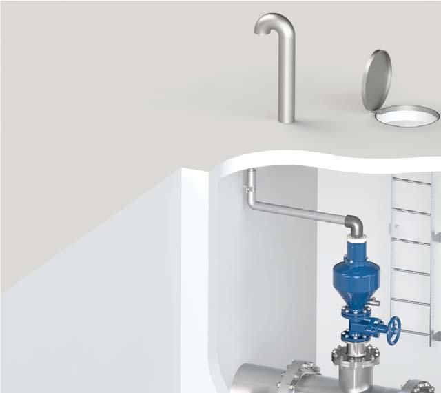
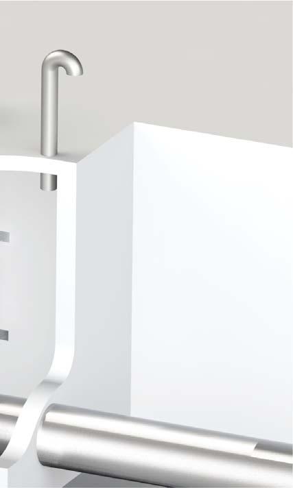
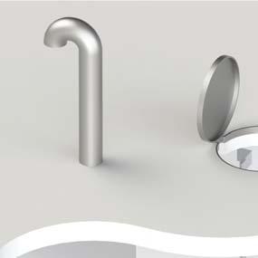
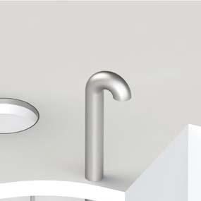
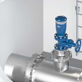
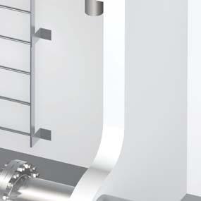
16 Applications of AS air valves for water works AS air valves are usually installed near pumps exposed to negative pressure in case of power failure, thanks to their performance they will allow the entrance of large volume of air avoiding negative pressure conditions on the system to contain upsurges during the second phase, by means of the anti-slam system with adjustable outflow. The picture shows CSA 3F AS anti-water hammer combination air valves located at the outlet of vertical pumps before the check valve, with CSA SUB air conveyance system, and at the outlet for air release and surge prevention. AS air valves are needed in presence of sectioning and/or modulating devices, usually installed upstream and downstream of them, both to protect the system during filling and set up operations and to prevent negative pressure during closures and interruption of the flow. The pictures shows an installation on a dead end in combination with CSA self-flushing pilot operated control valve Mod. XLC 450 P. The surge prevention system on the air valve when filling the pipeline is extremely important to avoid and prevent unwanted surge. 16


17 Applications of AS air valves for wastewater AS air valves are usually installed near pumps exposed to negative pressure in case of power failure, thanks to their performance they will allow the entrance of large volume of air avoiding negative pressure conditions on the system to contain upsurges during the second phase, by means of the anti-slam system with adjustable outflow. The picture shows CSA SCA 2" compact anti water hammer combination air valves located at the outlet of the submersible pumps before the check valve, and at the outlet for air release and surge prevention in combination with the CSA innovative surge tank AVAST (patent pending), which doesn t require any bladder or compressor. AS air valves are needed in presence of sectioning and/or modulating devices, usually installed upstream and downstream of them, both to protect the system during filling and set up operations and to prevent negative pressure during closures and interruption of the flow. The picture shows CSA anti water hammer combination air valves located on the changes in slope of a riser of a wastewater distribution system, with connections provided with check valves and isolation devices. 17


18 Application and sizing of air valves The proper sizing of air valves, carried out by CSA software AVS or through manual calculations, involves three steps and requires the pipeline profile with chainage and elevation of each point. The most important function of an air valve is to release air pockets out of the pipeline and to avoid negative pressure conditions. 1-Accumulation of air pockets The first step is to identify the locations where air pockets are likely to accumulate in working conditions like high points, changes in slope descending, long descents e sub-horizontal segments especially if subject to variation in flow reaching values below of the critical velocity, necessary for the hydraulic air removal. When installing air valves on location exposed to the gathering of air pockets it is advisable to create some sort of air trap also called accumulation chamber between the air valve and the pipeline. The pictures shows this concept with some indication in terms of size of this chamber user can follow as a rule of thumb, without exceeding a certain size in terms of DN to prevent vortex and turbulence from forming thus producing the opposite effect and affecting the proper air release. High points Change in slope descending Long descending, sub-horizontal segments Size of the accumulation chamber m d 0,5 d 0,3 d 18


 as a percentage of the pipe area (A pipe ).")
19 2-Pipe burst analysis The second step is to simulate pipe burst along the profile, in general on the lower parts of the profiles and at those locations considered to be critical if exposed to such unfortunate event, calculating the amount of water discharged. The same amount of air through the air valve during the intake, within allowable DP, will then have to be guaranteed for the proper protection of the system against negative pressure condition. With regard to that the formula to be used is the following, where DB is the diameter whose section has been obtained according to a burst % depending on the material, S is the slope, CR is the roughness coefficient and K is a dimensionless coefficient. Q B = K C R D B 2,63 S 0,54 The picture is showing the pipe burst, expressed in terms of section (A burst ) as a percentage of the pipe area (A pipe ). We always recommend to include a safety factor ranging from 1.5 to 3 depending on the material, soil, installation criteria and years of the pipeline. GRP, cement and thin pipeline in stainless steel will be more critical than DI for example. Below the chart expressing the average pipe burst values for the most common pipe materials. Pipe material HDPE GRP Cement Ductile cast iron Cast iron PVC Steel Average burst % A burst A pipe Pipeline slope (mm/m) Pipeline DN (mm) Q (l/s) Purely as an indication on the chart above is shown the amount of water discharged in case of steel pipes versus slope, assuming a burst percentage of 100, which is highly conservative. 19


20 During the pipe burst analysis the CSA software is performing a thorough analysis of the entire profile identifying the critical locations and locating automatically the air valves for high points, changes in slope ascending, descending long segments and sub-horizontal lines, then sized to cope with the most conservative scenario. Finally in presence of long and sub horizontal segments air valves shall be placed equally distanced with a spacing ranging between 400 and 800 meters depending on the application, pipeline and evaluation of transient phenomena. High point Q1 and Q2 are calculated, the higher value is then taken for the analysis. Q 2 Q 1 Q burst Q burst Change in slope descending Q1 and Q2 are calculated, the difference is obtained for the analysis Change in slope ascending Q1 and Q2 are calculated, the difference is obtained for the analysis Q 2 Q 1 Q 1 Q 2 Q burst Q burst Long descends, ascends, sub-horizontal segments Q1 and Q2 are calculated and used with air valves spacing ranging between 400 and 800 m Q 2 Q 1 Q 1 Q 2 Q burst Q burst 20


21 3-Pipe drainage analysis The third step is to simulate the draining phases by opening the drain valves where present and assessing the amount of water flowing out. With regard to that the formula to be used is the following, where D d is the DN of the gate valve, is the difference in pressure acting between the air valve and the drain, C d is the discharge coefficient ranging between 0,5 and 0,7 depending on the piping between the main transmission line and the gate valve, difference in DN, kind of sectioning device. For common installation a value of 0,61 is recommended. Q d = C d ( D d2 /4) (2 g 0,5 During the pipe drainage analysis the software methodology is the same, the main difference though is that the study is carried out only of those segments involved in negative pressure as a consequence of the opening of drains, which shall be specified by the customer in terms of DN and discharge coefficient. As an instance peaks and critical locations won t be examined if drains are not identified and created in the model. We always recommend to include a safety factor in this case ranging from 1.5 to 2 depending on the status of the drains, years of the pipeline and maintenance issues. The CSA AVS software built nr 3, all rights reserved, has been developed with a friendly windows interface and able to simulate air valves location and sizing in addition to steady state hydraulic analysis of profile, to determine head loss, HGL and the behavior of regulating devices and boundary conditions such as tanks, pumps, control valves, modulating devices, consumption and many more. Pipeline properties and mechanical properties are also taken into account for the analysis providing a preliminary indication of the collapsing value. CSA AVS uses many editor windows where user can input and calculate the profile with all the parameters and sizing methodology mentioned in this manual; allowable negative pressure, pipe burst and drain, air valves spacing are clearly identified. The software also includes specific algorithms: the first able to consider air valves refinement, when many changes in slopes occur in short segments and some of them are skipped due to project and installation requirements, the second takes into account the air valves reaction time during the opening phase and their behavior in presence of possible conditions likely to produce surges, for example rapid filling. The air valves sizing software is seamless integrated with the CSA dynamic program for water hammer and transient analysis. 21


, 20 is a proportionality constant, E is the modulus of elasticity (mpa), μ is the Poisson s ratio (0,4 for plastic), t is the pipewall thickness (mm), D is the pipe outside diameter (mm), C is")


22 Allowable negative pressure The main purpose of an air valve is to enter a volume of air equal to the amount of water discharge through steps 1 and 2 namely pipe burst and drainage analysis, producing a negative pressure value acceptable for the case study and depending on the pipe material, thickness, ID. If we discharge water of the main without replacing it by air entrance through the air valves we will inevitably experience negative pressure. Many problems are associated with this event like pipe deformation, possible collapse, movement of gaskets, entrance of contaminated water and pollution through segment of the pipe exposed to leakage. As an indication the maximum allowable pressure to be used the following formula is shown below where C is a safety factor usually 2, P C = 20 E (t/d) 3 (1- μ 2 C Where P C is the collapsing pressure (bar), 20 is a proportionality constant, E is the modulus of elasticity (mpa), μ is the Poisson s ratio (0,4 for plastic), t is the pipewall thickness (mm), D is the pipe outside diameter (mm), C is the safety factor (2 for negative pressure). For plastic pipe the pressure resistance versus temperature must also be taken into account as well as the material s decay if exposed to frequent negative pressure fluctuations. The concept air flow capacity is important for the proper analysis and air valves assessment, especially during the intake, as an example below a particular of air performance chart for CSA FOX combination anti hammer AS air valves full bore series. The three zones depicted on the chart are based upon CSA advise about how to use air valves with regards to the allowable differential pressure. The pipe tolerance to negative pressure should always be confirmed through static analysis and information provided by the pipe supplier, as general guideline we can identify them into A/B/C: A: recommended working condition with a maximum allowable negative of 0,1 bar B: working conditions with DI pipes with a maximum allowable negative of 0,2 bar C: damage working conditions with risk of pipe deformation, collapse. A negative pressure higher than 0,2 bar should never be exceeded AIR ENTRANCE DURING PIPE DRAINING p (bar) 0 1,0 0,9 0,8 0, Q (m 3 /h) C B A 0,6 0, DN 22


23 Air valves location The picture indicates the positioning and location of air valves on a pumping mains, applicable for water and wastewater use, with the selection between CSA combination anti surge air valves RFP and AS series according to the profile and propagation of the pressure wave in case of transient event, in this case represented by a sudden power failure. For long horizontal segments of the pipeline, between the air valves and the changes in slope, a simple air release model is advised. maximum points long horizontal runs AS AS Vent AS AS long changes descents in slope changes in slope Reservoir Pumps station RFP RFP RFP RFP RFP RFP RFP RFP drain valve drain valve drain valve drain valve Vent Automatic air release AS Anti-shock combination air valve RFP Rapid filling prevention combination air valve The picture indicates the positioning and location of air valves on a gravity fed pipeline, applicable for water and wastewater use, with the selection between CSA combination anti surge air valves RFP and AS series according to the profile and protection against possible transient events, in this case represented by sudden pipe filling and rapid flow variation caused for example by the level regulation device located downstream. 23


24 Installation - Water air valve with accumulation chamber Installation - Wastewater air valve with accumulation chamber and air conveyance system 24


25 Advanced testing facilities Designed to reproduce real conditions of modern water distribution systems the CSA testing facility is able to assess the dynamic performances of automatic control valves, direct acting pressure control valves, air valves and anti water hammer valves. Provided with a high capacity booster pumps station, and linked to an advanced high frequency pressure transducers and flow meters, the testing rig allows for a real time visualization of pressure and flow evolutions. Water hammer events can also be simulated and recorded to prove the efficacy of CSA fast acting relief valve, in addition to level control for which, using an auxiliary stilling tank, a part of the pipeline system is entirely dedicated. The PLC and control station allows for the operation of step by step and solenoid operated valves to determine the sensitivity of such kind of application and pressure management solutions. Thanks to this important and powerful tool valves can be customized, simulated and set according to the project requirements assuring the perfect performance and accuracy. The testing process All our valves undergo severe tests according to EN standards to ensure they are mechanically resistent, watertight, and high performing. After testing every valve is identified by means of a metallic tag or sticker, and duly registered and certified. 25


26 Water hammer analysis CSA Hyconsult CSA Hyconsult was founded to provide designers and consultants, involved in the design of water distribution and sewage systems, with accurate and unique technical support. CSA Hyconsult has specialized in hydraulic modelling and transients analysis, entirely through the use of modern computational tools and advanced algorithms. Simulations are essential to predict system responses to events under a wide range of conditions without disrupting the actual system. Using simulations, problems can be anticipated in possible or existing situations, and solutions can be evaluated in order to invest time, money and material in the most productive manner. Research and innovation CSA has always regarded knowledge as being indispensable for the kind of research that consistently feeds innovation at all levels. The R&D department at CSA constantly strives to improve product performance and continually searches for new solutions to meet our customer's needs. Twenty years of experience in valve design and sizing, supported by advanced computational tools, cooperation with external entities at the highest level, and test facilities for the verification of theoretical results which are available for our customers, guarantee our professionalism and reliability. 26
27 CSA s.r.l. - Strada San Giuseppe, 15 - località Ponteghiara Salsomaggiore Terme (PR) - Italy TEL FAX info@csasrl.it Rev. 1-4/2015
Wastewater combination air valve in stainless steel AISI 316 Mod. SCS
 Wastewater combination air valve in Mod. SCS The air valve guarantees the proper operation of sewage/industrial lines allowing the entrance of large quantity of air in case of pipe bursting or draining,
During the research and realisation of new products, CSA has always focused his efforts on: - Listening to the customer s needs and finding the best
 Water air valves The company was founded in 987 by transforming the former CSA, which was a trading company dealing with pipes and valves for water networks, into a manufacturing company, through the research
DAV - P. Product Catalogue DAV - P. Air release & Vacuum Break Valves. (Plastic Air Valves) DAV - P. Edition 2012
 DAV - P. Edition 2012") Product Catalogue DAV - P DAV - P Air release & Vacuum Break Valves Edition 1 DAV - P (Plastic Air Valves) DAV Series Overview General The presence of trapped air in a pressurized pipeline can have serious
Product Catalogue DAV - P DAV - P Air release & Vacuum Break Valves Edition 1 DAV - P (Plastic Air Valves) DAV Series Overview General The presence of trapped air in a pressurized pipeline can have serious
DAV - MP DAV - MP. Metallic-Shield Air Valves. Product Catalogue. (Metallic-Shield Air Valves) DAV - MP
 DAV - MP") DAV - MP Metallic-Shield Air Valves Product Catalogue DAV - MP DAV - MP (Metallic-Shield Air Valves) Edition 9/ DAV Series DAV-MP Overview General The presence of trapped air in a pressurized pipeline
DAV - MP Metallic-Shield Air Valves Product Catalogue DAV - MP DAV - MP (Metallic-Shield Air Valves) Edition 9/ DAV Series DAV-MP Overview General The presence of trapped air in a pressurized pipeline
Product Catalogue DAV - P DAV - P. Air release & Vacuum Break Valves. (Plastic Air Valves) DAV - P
 DAV - P") Product Catalogue DAV - P DAV - P Air release & Vacuum Break Valves DAV - P (Plastic Air Valves) DAV Series??? Overview General The presence of trapped air in a pressurized pipeline can have serious effects
Product Catalogue DAV - P DAV - P Air release & Vacuum Break Valves DAV - P (Plastic Air Valves) DAV Series??? Overview General The presence of trapped air in a pressurized pipeline can have serious effects
MITIGATING PIPE AND RISER HYDRAULIC PIPELINE ISSUES WITH THE I-RISER PLUS
 24 TH July 2013 MITIGATING PIPE AND RISER HYDRAULIC PIPELINE ISSUES WITH THE I-RISER PLUS Vern Costelow Business Development Consultant AWMA Water Control Solutions INTRODUCTION Surface irrigation is still
Journal of Applied Fluid Transients, Vol 1-1, April 2014 (3-1)
") Modeling and Field Verification Study of Air Slam Conditions on kalanit Pipeline System By Yiftach Brunner & Sathish Kumar ir valves are integral part of long water transmission mains and are essential
Modeling and Field Verification Study of Air Slam Conditions on kalanit Pipeline System By Yiftach Brunner & Sathish Kumar ir valves are integral part of long water transmission mains and are essential
PRESSURE SURGES IN PIPELINES
 CHAPTER 4 PRESSURE SURGES IN PIPELINES 4.1 FEATURES OF PRESSURE SURGE In the past, water engineers were facing problems with repeated pipe bursts, failing seals etc. They termed the cause of failure as
BERMAD Waterworks. Combination Air Valve. Air Valves Series. Typical Applications. Features & Benefits. Additional Features.
 BERMA Waterworks Combination Air Valve Model C7 BERMA C7 is a high quality combination air valve for a variety of water networks and operating conditions. It evacuates air during pipeline filling, allows
Theory, Application, and Sizing of Air Valves
 VM AV/WP White Paper Theory, Application, and Sizing of Air Valves Table of Contents Introduction...................... 2 Three Basic Types of Air Valves....... 2 Air Release Valves................. 3
DAV - WP DAV - WP. Wastewater Air Valves. Product Catalogue. (Wastewater Air Valves) DAV - WP
 DAV - WP") DAV - WP Wastewater Air Valves DAV - WP (Wastewater Air Valves) Product Catalogue DAV - WP DAV Series??? DAV-WP General DAV-WP Wastewater Air Valves The DAV-WP valve has been designed for efficient discharge
DAV - WP Wastewater Air Valves DAV - WP (Wastewater Air Valves) Product Catalogue DAV - WP DAV Series??? DAV-WP General DAV-WP Wastewater Air Valves The DAV-WP valve has been designed for efficient discharge
Combination Air Valve
 Combination Air Valve For Sewage and Wastewater Model C50 Installation, Operation and Maintenance Manual (IOM) Table of Contents General... Page 2 Safety... Page 2 Operational Data... Page 3 Materials
Tutorial. BOSfluids. Relief valve
 Tutorial Relief valve The Relief valve tutorial describes the theory and modeling process of a pressure relief valve or safety valve. It covers the algorithm BOSfluids uses to model the valve and a worked
UNIT 15 WATER HAMMER AND SURGE TANKS
 UNT 15 WATER HAMMER AND SURGE TANKS Structure 15.1 ntroduction Objectives 15.2 Water Hammer 15.2.1 Expression for Rise in Pressure 15.3 Rapid Acceleration of Flow 15.4 Surge Tanks 15.5 Summary 15.6 Keywords
BERMAD Fire Protection Hydraulic Control Valves
 BERMAD Fire Protection Hydraulic Control Valves Control Solutions with the Power to Protect BERMAD - The Company Since its foundation in 1965, BERMAD has focused its efforts on innovation, quality and
DAV Series. DAV-MH Air Release & Vacuum Break Valves
 DAV-MH Air Release & Vacuum Break Valves ISO 9 AVFI Pty Ltd 4 Enterprise Drive Bundoora Vic 383 p: 3 8467 f: 3 8467 99 e: avfi@avfi.com.au w: www.avfi.com.au General DAV-MH Air Release and Vacuum Break
Installation and operation Manual. Bermad Surge Anticipation Valve. Model No 435
 Instruction manual Bermad surge anticipation manual Model No 435 Installation and operation Manual Bermad Surge Anticipation Valve Model No 435 Bermad Water Technologies Rev 0 5/05/2015 7 Inglewood Drive,
Courses of Instruction: Controlling and Monitoring of Pipelines
 Courses of Instruction: Controlling and Monitoring of Pipelines Date December 2010 Dr. Peter Eschenbacher Partner Angergraben 4 85250 Altomünster Germany Tel. +49-(0)8254 / 99 69 57 Fax +49-(0)8254 / 99
TROUBLESHOOTING GUIDELINES
 TROUBLESHOOTING GUIDELINES PROBLEM: Performance 1. The most common problem in this area comes from inadequate flow to the LAKOS Separator(s). All LAKOS Separators operate within a prescribed flow range
Water Hammer In Irrigation Systems 1
 CIR828 1 G. A. Clark and D. Z. Haman 2 Irrigation system design includes pump sizing and selection, valve sizing and selection, and pipe sizing as well as the proper selection and placement of many other
OIL AND GAS INDUSTRY
 This case study discusses the sizing of a coalescer filter and demonstrates its fouling life cycle analysis using a Flownex model which implements two new pressure loss components: - A rated pressure loss
High Performance BSP Dial Up Pattern Pressure Reducing Valve
 See our full range online at: www.vip-ltd.co.uk High Performance BSP Dial Up Pattern Pressure Reducing Valve VIP Product Code 31/0103 FUNCTION Pressure reducing valves are devices which, when installed
Theory, Applications and Sizing of Air Valves
 Practice + Operations Theory, Applications and Sizing of Air Valves Val-Matic Valve & Mfg. Corp. When air is allowed to accumulate in pressurized pipelines, efficiency is sacrificed and serious damage
THE WAY THE VENTURI AND ORIFICES WORK
 Manual M000 rev0 03/00 THE WAY THE VENTURI AND ORIFICES WORK CHAPTER All industrial combustion systems are made up of 3 main parts: ) The mixer which mixes fuel gas with combustion air in the correct ratio
44 (0) E:
 E:") FluidFlow Relief Valve Sizing Handbook Flite Software 2016 Flite Software N.I. Ltd, Block E, Balliniska Business Park, Springtown Rd, Derry, BT48 0LY, N. Ireland. T: 44 (0) 2871 279227 E: sales@fluidflowinfo.com
FluidFlow Relief Valve Sizing Handbook Flite Software 2016 Flite Software N.I. Ltd, Block E, Balliniska Business Park, Springtown Rd, Derry, BT48 0LY, N. Ireland. T: 44 (0) 2871 279227 E: sales@fluidflowinfo.com
VACUVENT VE SERIES CATALOGUE
 VACUVENT VE SERIES CATALOGUE October 2018 " ba f wa e " The Triple Function Air Valve Vacuvent offers a tri function air valve that not only breaks vacuum, but also reduces surge on pipeline filling and
Flanged pressure reducer/stabilizer VRCD
 Flanged pressure reducer/stabilizer VRCD 2 This unit reduces and stabilizes the upstream pressure by operating on its load losses with a constant downstream pressure irrespective of the rate of flow value.
CVEN 311 Fluid Dynamics Fall Semester 2011 Dr. Kelly Brumbelow, Texas A&M University. Final Exam
 CVEN 311 Fluid Dynamics Fall Semester 2011 Dr. Kelly Brumbelow, Texas A&M University Final Exam 8 pages, front & back, not including reference sheets; 21 questions An excerpt from the NCEES Fundamentals
LAKOS Waterworks. PWC Series Sand Separators. Installation & Operation Manual LS-829 (10/12)
") LAKOS Waterworks PWC Series Sand Separators Installation & Operation Manual LS-829 (10/12) Table of Contents Separator Operation... 3 Individual Model Details.... 4 Flow vs. Pressure Loss Chart 4 Installation
LAKOS Waterworks PWC Series Sand Separators Installation & Operation Manual LS-829 (10/12) Table of Contents Separator Operation... 3 Individual Model Details.... 4 Flow vs. Pressure Loss Chart 4 Installation
ANNEX AMENDMENTS TO THE INTERNATIONAL CODE FOR FIRE SAFETY SYSTEMS (FSS CODE) CHAPTER 15 INERT GAS SYSTEMS
 CHAPTER 15 INERT GAS SYSTEMS") Annex 3, page 2 ANNEX AMENDMENTS TO THE INTERNATIONAL CODE FOR FIRE SAFETY SYSTEMS (FSS CODE) CHAPTER 15 INERT GAS SYSTEMS The text of existing chapter 15 is replaced by the following: "1 Application This
Annex 3, page 2 ANNEX AMENDMENTS TO THE INTERNATIONAL CODE FOR FIRE SAFETY SYSTEMS (FSS CODE) CHAPTER 15 INERT GAS SYSTEMS The text of existing chapter 15 is replaced by the following: "1 Application This
PIG MOTION AND DYNAMICS IN COMPLEX GAS NETWORKS. Dr Aidan O Donoghue, Pipeline Research Limited, Glasgow
 PIG MOTION AND DYNAMICS IN COMPLEX GAS NETWORKS Dr Aidan O Donoghue, Pipeline Research Limited, Glasgow A model to examine pigging and inspection of gas networks with multiple pipelines, connections and
Applied Fluid Mechanics
 Applied Fluid Mechanics 1. The Nature of Fluid and the Study of Fluid Mechanics 2. Viscosity of Fluid 3. Pressure Measurement 4. Forces Due to Static Fluid 5. Buoyancy and Stability 6. Flow of Fluid and
AIRFLOW GENERATION IN A TUNNEL USING A SACCARDO VENTILATION SYSTEM AGAINST THE BUOYANCY EFFECT PRODUCED BY A FIRE
 - 247 - AIRFLOW GENERATION IN A TUNNEL USING A SACCARDO VENTILATION SYSTEM AGAINST THE BUOYANCY EFFECT PRODUCED BY A FIRE J D Castro a, C W Pope a and R D Matthews b a Mott MacDonald Ltd, St Anne House,
BERMAD Waterworks. Level Control Valve with Altitude Pilot. 700 Series. Model X. Features and Benefits. Major Additional Features
 Level Control Valve with Altitude Pilot High level reservoirs & water towers Energy cost critical systems Systems with poor water quality Inherent refreshing Level sustaining at reservoir outlet The Level
Unit 24: Applications of Pneumatics and Hydraulics
 Unit 24: Applications of Pneumatics and Hydraulics Unit code: J/601/1496 QCF level: 4 Credit value: 15 OUTCOME 2 TUTORIAL 9 ACCUMULATORS The material needed for outcome 2 is very extensive so there are
The Future of Hydraulic Control in Water-Systems
 The Future of Hydraulic Control in Water-Systems A. Heimann Manager of R&D and of Technical Support & Applications Engineering departments at Dorot Automatic Control Valves Dorot Control Valves, Kibbutz
Pressure surge absorption
 Pressure surge absorption Product range for drinking water, waste water and the chemical industry With remote monitoring, everything is fully under control. Willy Zahnd, WARET AG PRESSURE SURGE ABSORPTION
2 FUSION FITTINGS FOR USE WITH POLYETHYLENE PRESSURE PIPES DESIGN FOR DYNAMIC STRESSES
 Industry Guidelines Part 2 FUSION FITTINGS FOR USE WITH POLYETHYLENE PRESSURE PIPES DESIGN FOR DYNAMIC STRESSES ISSUE 5.1 Ref: POP10B 15 MAR 2010 Disclaimer In formulating this guideline PIPA has relied
OIL SUPPLY SYSTEMS ABOVE 45kW OUTPUT 4.1 Oil Supply
 OIL SUPPLY SYSTEMS ABOVE 45kW OUTPUT 4.1 Oil Supply 4.1.1 General The primary function of a system for handling fuel oil is to transfer oil from the storage tank to the oil burner at specified conditions
TECHNICAL DATA. Q = C v P S
 Page 1 of 13 1. DESCRIPTION The Viking 6 Model G-6000 Dry Valve Riser Assembly consists of a small profile, light weight, pilot operated valve that is used to separate the water supply from the dry sprinkler
Description. Functions. Technical data. Applications. Tests. On-Off 2 levels float control valve, closing at high level and opening at low level.
 DN 0 to 1000 - Serie K3 0 On-Off levels float control valve, closing at high level and opening at low level. Functions Prevents overflowing and closes at a constant and adjustable high level. Remains closed
300 Series. Automatic Hydraulic Control Valves
 Automatic Hydraulic Control Valves AVFI Pty Ltd 54 Enterprise Drive Bundoora Vic 3083 p: 03 8467 0000 f: 03 8467 0099 e: avfi@avfi.com.au w: www.avfi.com.au 300 Series General 300 SERIES Automatic Hydraulic
POP Safety Valve. POP Safety Valve INTRODUCTION DEFINITIONS
 POP Safety Valve POP Safety Valve INTRODUCTION The effects of exceeding safe pressure levels in an unprotected pressure vessel or system, can have catastrophic effects on both plant and personnel. Safety
776 Cryogenic Safety Valve
 776 Cryogenic Safety Valve INTRODUCTION 776 Cryogenic Safety Valve The effects of exceeding safe pressure levels in an unprotected pressure vessel or system, can have catastrophic effects on both plant
VACUVENT Valve functions - benefits - flowpath - VG series - Sewage
 01 VG Series air release and vacuum break valves Operation and benefits The topic of sizing and placement is significant and complex the purpose of this document is simply to point out important considerations
Optimizing Gas Supply for Industrial Lasers
 Optimizing Gas Supply for Industrial Lasers Laser cutting of metals and other materials has grown rapidly due to developments in laser power, advancements in CNC automation, and decreasing costs. The industrial
EDUCTOR. principle of operation
 EDUCTOR principle of operation condensate and mixing eductor s are designed to mix two liquids intimately in various proportions in operations where the pressure liquid is the greater proportion of the
Unsteady Flow in Pipes
 The Islamic University of Gaza Faculty of Engineering Civil Engineering Department Hydraulics - ECIV 3322 Chapter 4 Unsteady Flow in Pipes Water Hammer Phenomenon in pipelines A sudden change of flow rate
THE INFLOW OF UNWANTED AIR
 IN PRESSURIZED PIPES The main reason for the inflow of air in public water distribution systems is excessive water velocity. Air traveling with water in pressurized pipes can result in high turbulence
Operational Settings:
 instrucalc features more than 70 routines associated with control valves, ISO flow elements, relief valves and rupture disks, and calculates process data at flow conditions for a comprehensive range of
Suppress Your Surges: Surge Suppression Fundamentals. April 13, 2017
 Suppress Your Surges: Surge Suppression Fundamentals April 13, 2017 How Bad Can Waterhammer Really Be? 2 Workshop Agenda What is waterhammer? Causes of waterhammer Instantaneous surge pressures Surges
Free Surface Flow Simulation with ACUSIM in the Water Industry
 Free Surface Flow Simulation with ACUSIM in the Water Industry Tuan Ta Research Scientist, Innovation, Thames Water Kempton Water Treatment Works, Innovation, Feltham Hill Road, Hanworth, TW13 6XH, UK.
Models 461-S, 461-8S and S Regulators. R-1330 Rev. 7
 Models 461-S, 461-8S and 461-12S Regulators R-1330 Rev. 7 461-S, 461-8S and 461-12S Regulators The Sensus Models 461-S, 461-8S and 461-12S are balanced valve, spring type regulators designed for distribution
Air Eliminators and Combination Air Eliminators Strainers
 Description Air Eliminators and Combination Air Eliminator Strainers are designed to provide separation, elimination and prevention of air in piping systems for a variety of installations and conditions.
FLUID POWER FLUID POWER EQUIPMENT TUTORIAL ACCUMULATORS. This work covers part of outcome 2 of the Edexcel standard module:
 FLUID POWER FLUID POWER EQUIPMENT TUTORIAL ACCUMULATORS This work covers part of outcome 2 of the Edexcel standard module: UNIT 21746P APPLIED PNEUMATICS AND HYDRAULICS The material needed for outcome
A centrifugal pump consists of an impeller attached to and rotating with the shaft and a casing that encloses the impeller.
 Centrifugal pump How centrifugal pumps work A centrifugal pump consists of an impeller attached to and rotating with the shaft and a casing that encloses the impeller. In centrifugal pump, liquid is forced
CONTROL VALVE TESTING
 The optimal functioning of the Control valve not only exists of sufficient body & seat tightness, but more important, the total "performance" of the valve and its controls! For an accurate and reliable
TECHNOLOGIES. M Series. Positive return metering pumps [API675]
![TECHNOLOGIES. M Series. Positive return metering pumps [API675]](/thumbs/90/101415964.jpg "TECHNOLOGIES. M Series. Positive return metering pumps [API675]") M Series Positive return metering pumps [API675] Hydraulic double diaphragm metering pump in AISI 316L stainless steel A line of plunger and hydraulic double diaphragm metering pumps designed according
M Series Positive return metering pumps [API675] Hydraulic double diaphragm metering pump in AISI 316L stainless steel A line of plunger and hydraulic double diaphragm metering pumps designed according
IFS NUVENT SERIES IWF FOR POTABLE WATER ANTI SLAM AIR RELEASE AND VACUUM BREAK AIR VALVES
 IFS NUVENT SERIES IWF FOR POTABLE WATER ANTI SLAM AIR RELEASE AND VACUUM BREAK AIR VALVES CONTENTS About IFS High volume air discharge Curves and operation Anti slam air discharge Curves and operation
CASE STUDY. Elvington To Brayton Barff Air valve replacement Program
 CASE STUDY Elvington To Brayton Barff Air valve replacement Program Vent-O-Mat Anti-Shock Air valves have helped Yorkshire Water reduce maintenance costs, reduces surge and improve flows in their trunk
Combination Air Valve Model
 Combination Air Valve Model Model C10 /C11 Installation, Operation and Maintenance Manual (IOM) Table of Contents General...Page 2 Safety...Page 2 Operational Data...Page 3 Materials and Connections...Page
Pressure reducing valves Index
 Index General information page Introduction 506 General introduction 507 for a steam plant 509 Product information BSP thread page Brass 510 ; BSP female thread 511 ; BSP male thread 513 Stainless steel
TECHNICAL DATA. Page 1 of 12
 Page 1 of 12 1. DESCRIPTION The Viking Regulating Valve is a direct-acting, single-seated, spring-loaded diaphragm valve. When installed as a pilot regulating valve on a Viking Model H or J Flow Control
Akasison Flow phenomena of a siphonic roof outlet
 Akasison Flow phenomena of a siphonic roof outlet Ir. Marc Buitenhuis MTD Hydraulic research engineer Akatherm BV, Panningen, The Netherlands 06-01-2011 Abstract So far the investigations on siphonic roof
Spilt body Flange ball valve. TC-205MFF-PN1640 User Manual English Version. Document No: TC-205MFF-PN1640.Ur-manual. Date: 2007/04/2617. Version: 1.
 Spilt body Flange ball valve TC-205MFF-PN1640 Series PED Category I,II TC-205MFF-PN1640 User Manual English Version Use for company in Europe who will place the product on the market, please amend which
HANDBOOK SAFETY DEVICES. Ed SAFETY DEVICES DS-ED 01/ ENG 1
 HANDBOOK Ed. 2017 DS-ED 01/2017 - ENG 1 CHAPTER 9 BURSTING DISC DEVICES IN SERIES 3070 SCOPE Use: protection against possible overpressure of the apparatuses listed below, with regard to the operating
FUNDAMENTALS OF PRESSURE REGULATORS ROBERT BENNETT MANAGER OF TRAINING ELSTER AMERICAN METER
 FUNDAMENTALS OF PRESSURE REGULATORS ROBERT BENNETT MANAGER OF TRAINING ELSTER AMERICAN METER SUPPLY = DEMAND FUNCTION OF A REGULATOR A regulator may be defined as a "mechanism for controlling or governing
TECHNICAL DATA. Low-Flow Foam Preaction System with Hydraulically Actuated Concentrate Control Valve.
 Foam 302 a 1. DESCRIPTION (Refer to Figure 1 on page 302 e.) The Viking Low-Flow Foam/Water Proportioning System is a UL Listed and FM Approved system, for use with 3M and Viking brand foam concentrate.
DR.ING. CARLO AVANZINI PROFESSIONAL ENGINEER GRIP TEST REPORT NOVA SIRIA, ROLETTO, Premise
 GRIP TEST REPORT NOVA SIRIA, ROLETTO, 07.10.2013 1. Premise The present report covers the witnessing of the test conducted in the Nova Siria Factory in Roletto (Torino, Italy) to verify the behavior of
DNVGL-CP-0187 Edition March 2016
 CLASS PROGRAMME Type approval DNVGL-CP-0187 Edition March 2016 The electronic pdf version of this document, available free of charge from http://www.dnvgl.com, is the officially binding version. FOREWORD
Transient Analyses In Relief Systems
 Transient Analyses In Relief Systems Dirk Deboer, Brady Haneman and Quoc-Khanh Tran Kaiser Engineers Pty Ltd ABSTRACT Analyses of pressure relief systems are concerned with transient process disturbances
BACK PRESSURE / SUSTAINING
 In many liquid piping systems, it is vital that line pressure is maintained within relatively narrow limits. This is the function of the 108 Pressure Relief / Back Pressure Series of the OCV control valves.
PIPELINE DESIGN, OPERATION AND MAINTENANCE COURSE CONTINUING PROFESSIONAL DEVELOPMENT RESULTS SHEET
 E1 BASIC PIPELINE DESIGN Question Description Solution E1Q1 Calculated pipe diameter = Commercial diameter = Pipe material = 283 mm 315 mm mpvc E1Q2 E1Q3 Maximum pressure downstream of pump based on calculated
THE IMPACT ON ENERGY CONSUMPTION CAUSED BY PRESSURE DROP IN A COMPRESSED AIR SYSTEM
 THE IMPACT ON ENERGY CONSUMPTION CAUSED BY PRESSURE DROP IN A COMPRESSED AIR SYSTEM What is pressure drop in a compressed air utility? Pressure drop is a term used to characterize the reduction in air
TECHNICAL DATA 3 MODEL G-3000 DRY VALVE RISER ASSEMBLY
 Page 1 of 13 1. DESCRIPTION The Viking 3 Model G-3000 Dry Valve Riser Assembly is equipped with a small profile, light weight, pilot operated valve that is used to separate the water supply from the dry
Laboratory studies of water column separation
 IOP Conference Series: Materials Science and Engineering OPEN ACCESS Laboratory studies of water column separation To cite this article: R Autrique and E Rodal 2013 IOP Conf. Ser.: Mater. Sci. Eng. 52
HYDRAULICS. H89.8D - Hydraulic Bench
 HYDRAULICS H89.8D - Hydraulic Bench 1. General The H89.8D and ancillary equipment have been developed to provide a comprehensive range of experiments in fluid mechanics. The bench is of robust construction
TECHNICAL DATA Q= C. Table 1 - Specifications
 September 25, 2013 Pressure Regulation 537a 1. Description The Model B-3 Pilot Operated Pressure Control Valve is a factory assembled unit. The unit consists of a Model J-2 Halar coated Flow Control Valve,
TECHNICAL DATA. than the water inlet pressure to the concentrate
 Foam102a 1. DESCRIPTION The Viking Low Flow Foam/Water proportioning system, is a UL Listed and FM Approved system, for use with 3M foam concentrates. This system consists of a standard wet pipe sprinkler
TECHNICAL DATA. Pressure Regulation 531a. April 24, 2009
 April 24, 29 Pressure Regulation 531a 1. DESCRIPTION The Viking Regulating Valve is a direct-acting, single-seated, spring-loaded diaphragm valve. When installed as a pilot regulating valve on a Viking
ASX 176 Axial Pressure regulator
 ASX 176 Axial Pressure regulator ASX 176 Classification and Area of Application ASX 176 is a downstream pressure regulator, pilot controlled, for medium and high pressure applications. It is particularly
Tirpur Area Water Supply Project A Report on Transient Modeling Study
 y February 2008 1 of 81 y INTRODUCTION: The report presents results from a transient modeling study conducted on the clear water transmission main of Tirpur Areas Water Supply Project, Tamilnadu, India.
Safety devices for overpressure protection. Rupture discs: applications, sizing, and types
 Safety devices for overpressure protection. Rupture discs: applications, sizing, and types Milano, 18 Aprile 2018 Auditorio TECNIMONT Cristian Barbi and Mario Modena DonadonSDD Summary Devices for overpressure
BACK PRESSURE / SUSTAINING
 SPECIFICATIONS DIMENSIONS In many liquid piping systems, it is vital that line pressure is maintained within relatively narrow limits. This is the function of the 108 Pressure Relief / Back Pressure Series
Slam Shut Valves SCN
 Slam Shut Valves SCN SCN > Slam shut valves Introduction SCN is a compact safety device (SAV) which quickly intercept gas flow whenever the pressure under monitoring reaches a pre-set limits, or whenever
Compiled by: B Beard. Approved by: SH Carstens. Description of requirements and procedures for compact provers to be used as verification standards.
 1. Scope Description of requirements and procedures for compact provers to be used as verification standards. 2. Reference documents Trade Metrology Act SANS1698 3. Policy A. BASIC REQUIREMENTS Compact
TECHNICAL DATA CAUTION
 Page 1 of 12 1. DESCRIPTION The Viking Model C-2 Pilot Pressure Regulating Valve is a direct-acting, single-seated, spring-loaded diaphragm valve. When installed as a pilot regulating valve on a Viking
SUMMARY OF THE EXPERIMENTAL STUDIES OF COLD HELIUM PROPAGATION ALONG A SCALE MODEL OF THE LHC TUNNEL
 EUROPEAN ORGANIZATION FOR NUCLEAR RESEARCH European Laboratory for Particle Physics Large Hadron Collider Project LHC Project Report 684 SUMMARY OF THE EXPERIMENTAL STUDIES OF COLD HELIUM PROPAGATION ALONG
BEFORE SALES AFTER SALES
 TALIS FP RANGE TALIS FP RANGE TALIS is a leading global provider of premium valves, hydrants and control solutions for water flow control and Fire Protection Systems With a varied range of products, Talis
(Refer Slide Time: 2:16)
") Fluid Machines. Professor Sankar Kumar Som. Department Of Mechanical Engineering. Indian Institute Of Technology Kharagpur. Lecture-23. Diffuser and Cavitation. Good morning and welcome you all to this
Fluid Machines. Professor Sankar Kumar Som. Department Of Mechanical Engineering. Indian Institute Of Technology Kharagpur. Lecture-23. Diffuser and Cavitation. Good morning and welcome you all to this
VALVES HIDROMATIC VALVE.
 VALVES HIDROMATIC VALVE Hydrodynamic design The Hidromatic valve of Hidroconta is a piston hydraulic valve controlled with the same fluid of the conduction. Its balloon design improves its hydrodynamic
CAST IRON SAFETY VALVE TYPE 6301
 CHARACTERISTICS The 6301 safety valve is dedicated to protect the equipment from potential overpressure. This is an automatic device that closes when the pressure conditions are back to normal. It is a
Sapag Control valve MONOVAR
 MONOVAR MONOVAR is the energy dissipating valve Features MONOVAR DN 2000 (80 ) Extremely simple design (patented) Excellent cavitation characteristics Very accurate flow or pressure control Manual or automatic
NEW TYPE M PRESSURE RELIEF DEVICE
 NEW TYPE M PRESSURE RELIEF DEVICE M PRESSURE RELIEF DEVICE ACCORDING TO EN 50216-5/A2 PATENTED 2 PRESSURE RELIEF DEVICE TYPE 50 M Section A-A 170 139 Transformer tank F 41.5 3 ø48.3 ø166 A P.R.D. TAG A
TECHNICAL DATA. Q= Cv S
 Page 1 of 13 1. DESCRIPTION The Viking 4 inch Model G-4000 Dry Valve Riser Assembly consists of a small profile, light weight, pilot operated valve that is used to separate the water supply from the dry
Pumping Systems for Landscaping Pumps, Controls and Accessories. Mark Snyder, PE
 October 21, 2010 Pumping Systems for Landscaping Pumps, Controls and Accessories Mark Snyder, PE Pump Station Design Purpose of Pump Stations Pump stations are designed to boost water pressure from a lower
Sizing Pulsation Dampeners Is Critical to Effectiveness
 Sizing Pulsation Dampeners Is Critical to Effectiveness Pressure variation is an important consideration when determining the appropriate size pulsation dampener needed for an application. by David McComb,
Pre-adjustable pressure reducing valves with self-contained cartridge
 Pre-adjustable pressure reducing valves with self-contained cartridge 535..H series ACCREDITED ISO 91 FM 15 15/17 GB replaces 15/1GB Function Pressure reducing valves are devices which, when installed
INSTALLATION, OPERATION AND MAINTENANCE HANDBOOK
 INSTALLATION, OPERATION AND MAINTENANCE HANDBOOK XLC 430 FLOW CONTROL VALVE INSTALLATION, OPERATION AND MAINTENANCE HANDBOOK Model XLC 430 This handbook provides information about the installation, operation
Evaluating Surge Potential in CSO Tunnels
 14 Evaluating Surge Potential in CSO Tunnels Karen E. Ridgway Tunnels are being proposed to control combined sewer overflow (CSO) in numerous cities in the United States and Canada. The tunnels are intended