Q-Use of intercostals guiders, Use to give extra strength to the particular area which require There are locally fixed longitudinal where more strengt
|
|
|
- Lucinda McDowell
- 5 years ago
- Views:
Transcription
1 Ships Construction Short Notes Q-Sections using in ships building Furthermore, Plates -The basic material of shipbuilding. Rectangular Bars -Are sometimes used for stem bars and similar purposes. Flat Bars-Thin rectangular bars or narrow pieces of plate, often used in welded work. Round Bars -Solid round bars are used for small pillars, handrails, etc. Half-round Bars (Sketch D)-Sometimes fitted as chafing pieces, etc. Angle Bars -Used for connecting arts together r for stiffening plating. Bulb Angles -A form of angle bar in which one flange is stiffened by enlarging the edge into a bulb, thus making it stronger than an angle of the same size. Channel Bars -stronger section than the bulb angle, used where greater strength is required. Zed Bars -Similar to the Channel, except that one flange is reversed. Not often used. H, or 1 Sections-A very strong section. It is not used generally, but is fitted where special strength is needed. T-Bars -Are sometimes used for special purposes, such as beams under wood decks. T Bulb Bars (Sketch LFA stronger form of T-bar. Bulb Plates (Sketch M)-Narrow plates with a bulb on one edge, used for welded work in lieu of riveted bulb-angles sometimes called" bulb bars". Inverted Angles (Sketch N)-An angle, welded to plating as shown, to serve the same purpose as a riveted channel bar. Inverted T-Bar Occasionally used, welded to plating, to form a kind of H-section. Page 1

2 Q-Use of intercostals guiders, Use to give extra strength to the particular area which require There are locally fixed longitudinal where more strength required. They are not running continuously as longitudinal. They are located in places such as loading heavy, under the M/E, under container shoes, Q-Water tight floor It uses to make separate compartments, such as tanks fully watertight. No opening in between Bottom longitudinal are piercing the water tight floor but has been welded to make water tight. Q-Transversally framed DB tank/solid floor/bracket floor When transversely framed, the double-bottom structure consists of solid plate floors and bracket floors with transverse frames. The bracket floor is fitted between the widely spaced solid floors. It consists of transverse bulb angle sections stiffening the shell and inner bottom plating. Vertical support is provided by brackets at the side shell and center girder, any side girders and intermediate struts. The number of Intercostal side girders fitted is determined by classification society rules. Page 2


3 Q-Solid floor Fitted for strengthening the bottom transversally and support inner bottom They are running transversely from continuous center girder to bilge Manholes provided for access through tanks and lightning holes are cut in each solid floor Small air and drain holes are drilled at the top and the bottom respectively of the solid floor in the tank space Locating between two watertight floors These are fitted at every frame spaces in engine room and in the pounding reagion. Q-Bracket floor The bracket floor is fitted between the widely spaced solid floors. It consists of transverse bulb angle sections stiffening the shell and inner bottom plating. Vertical support is provided by brackets at the side shell and center girder, any side girders and intermediate struts. The number of intercostals side girders fitted is determined by classification society rules. Q-Double-bottom structure The minimum depth is determined by rule requirements for the size of vessel but the actual depth is sometimes increased in places to suit double-bottom tank capacities. The structure is made up ofvertical floors which may be watertight, solid or of bracket construction. The floor structure is continuous from the center girder to the side shell and supports the inner bottom shell. Side girders are fitted in the longitudinal direction, their number depending on the width of the ship. These side girders are broken either side of the floors and are therefore termed intercostal girders. Watertight or oiltight floors are fitted beneath the main bulkheads and are also used to subdivide the double-bottom space into tanks for various liquids. Solid plate floors of non-watertight construction, usually lightened by manholes, are positioned in other places as required to stiffen the structure. Between solid plate floors, bracket floors are fitted. Bracket Page 3


4 floors consist of plate brackets attached to the center girder and the side shell with bulb plate stiffeners running between. The stiffeners are supported by angle bar struts at intervals and any side girders which are present in the structure. The arrangement of flooring will be determined by the type of framing system adopted, which may be either transverse or longitudinal. Q-Longitudinally frame DB Tank/solid floor/bracket floor This is the system favored as a result of tests and it provides adequate resistance to distortion on ships of 120 m in length or greater. Offset bulb plates are used as longitudinal stiffeners on the shell and inner bottom plating, at intervals of about 1 m. Solid floors provide support at transverse Bulkheads and at intervals not exceeding 3.8 m along the length of the ship. Brackets are fitted at the center girder and side shell at intermediate frame spaces between solid floors. These brackets are flanged at the free edge and extend to the first longitudinal. Channel bar or angle bar struts are provided to give support at intervals of not more than 2.5 m where solid floors are widely spaced. Intercostal side girders are again fitted, their number depending upon classification society rules. Access to the double-bottom tanks is usually by manholes cut in the tank top. These manholes are suitably jointed and bolted to be completely watertight when not in use. Docking plugs are fitted in all double-bottom tanks and are a means of completely draining these tanks for inspection in drydock. Air pipes are fitted to all double-bottom tanks to release the air when filling. Sounding pipes are also fitted to enable the tanks to be sounded and their capacity determined. All doublebottom tanks are tested on completion by the maximum service pressure head of water or an quivalent air test. Page 4
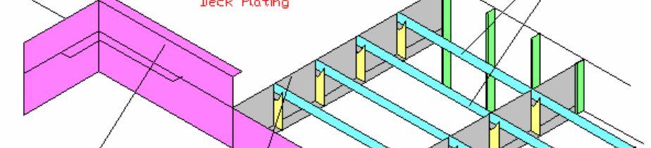
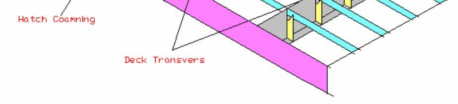
5 Q-Longitudinally framed deck Page 5


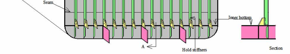
6 Q-Transversely framed deck Bulkheads The transverse watertight bulkheads subdivide the ship into a number of watertight Compartments and their number is dictated by classification society regulations. Oiltight Bulkheads form the boundaries of tanks used for the carriage of liquid cargoes or fuels. Nonwatertight bulkheads are any other bulkheads such as engine casings, accommodation partitions or stores compartments. Watertight bulkheads In addition to subdividing the ship, transverse bulkheads also provide considerable structural strength as support for the decks and to resist deformation caused by broadside waves (racking). The spacing of watertight bulkheads, which is known as the watertight subdivision of the ship, is governed by rules dependent upon ship type, size, etc. All ships must have: (1) A collision or fore peak bulkhead which is to be positioned not less than 0.05 X length of the Ship, nor more than 0.08 X length of the ship, from the forward end of the load waterline. (2) An after peak bulkhead which encloses the stern tube(s) and rudder trunk in a watertight Compartment. (3) A bulkhead at each end of the machinery space; the after bulkhead may, for an aft engine room, be the after peak bulkhead. Additional bulkheads are to be fitted according to the vessel's length, e.g. a ship between 145 and 165 m long must have 8 bulkheads with machinery midship and 7 bulkheads with machinery aft. Fitting less than the standard number of bulkheads is permitted in approved circumstances Where additional structural compensation is provided. Watertight bulkheads must extend to the freeboard deck but may rise to the uppermost continuous deck. The aft peak bulkhead may extend only to the next deck above the load waterline, where the construction aft of this deck is fully watertight to the shell. The purpose of watertight subdivision and the spacing of the bulkheads is to provide an arrangement such that if one compartment is flooded between Page 6


7 bulkheads the ship's waterline will not rise above the margin line. The margin line is a line drawn parallel to and 76 mm below the upper surface of the bulkhead deck at the ship's side. The subdivision of passenger ships is regulated by statutory requirements which are in excess of classification society rules for cargo ships, but the objects of confining flooding and avoiding sinking are the same. Q-Construction of watertight bulkheads Watertight bulkheads, because of their large area, are formed of several strakes of plating. They are welded to the shell, deck and tank top. The plating strakes are horizontal and the stiffening is vertical. Since water pressure in a tank increases with depth and the watertight bulkhead must withstand such loading, the bulkhead must have increasingly greater strength towards the base. This is achieved by increasing the thickness of the horizontal strakes of plating towards the bottom. The collision bulkhead must have plating some 12% thicker than other watertight bulkheads. Also, plating in the aft peak bulkhead around the stemtube must be doubled or increased in thickness to reduce vibration. The bulkhead is stiffened by vertical bulb plates or toe-welded angle bar stiffeners spaced about 760 mm apart. This spacing is reduced to 610 mm for collision and oiltight bulkheads. The ends of the stiffeners are bracketed to the tank top and the deck beams. In tween decks, where the loading is less, the stiffeners may have no end connections Page 7

8 Page 8
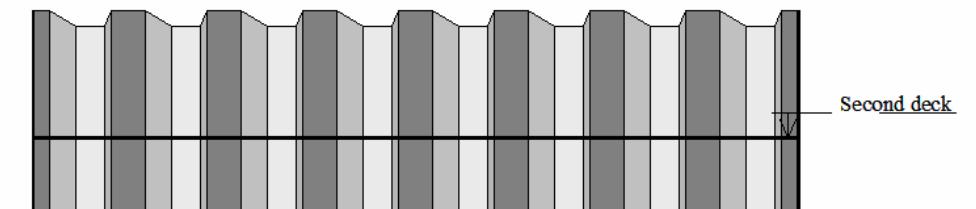
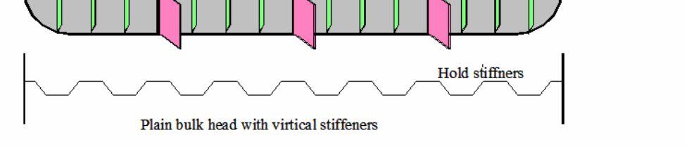
9 Q-Corrugated watertight bulkheads The use of corrugations or swedges in a plate instead of welded stiffeners produces as strong a structure with a reduction in weight. The troughs are vertical on transverse bulkheads but on longitudinal bulkheads they must be horizontal in order to add to the longitudinal strength of the ship. The corrugations or swedges are made in the plating strakes prior to fabrication of the complete bulkhead. As a consequence, the strakes run vertically and the plating must be of uniform thickness and adequate to support the greater loads at the bottom of the bulkhead. This greater thickness of plate offsets to some extent the saving in weight through not adding stiffeners to the bulkhead. The edges of the corrugated bulkhead which join to the shell plating may have a stiffened flat plate fitted to increase transverse strength and simplify fitting the bulkhead to the shell. On high bulkheads with vertical corrugations, diaphragm plates are fitted across the troughs. This prevents any possible collapse of the corrugations. A watertight floor is fitted in the double bottom directly below every main transverse bulkhead. Where a watertight bulkhead is penetrated, e.g. by pipework, a watertight closure around the penetration must be ensured by a collar fully welded to the pipe and the bulkhead. Q-Testing of watertight bulkheads The main fore and aft peak bulkheads must be tested by filling with water to the load waterline. Subdividing watertight bulkheads are tested by hosing down. Oiltight and tank bulkheads must be tested by a head of water not less than 2.45 m above the highest point of the tank. Q-Non-watertight bulkheads Any bulkheads other than those used as main subdivisions and tank boundaries may be nonwatertight. Examples of these are engine room casing bulkheads, accommodation partitions, store room divisions, etc. Wash bulkheads fitted in deep tanks or in the fore end of a ship are also examples of non-watertight bulkheads. Where a non-watertight bulkhead performs the supporting function similar to a pillar, its stiffeners must be adequate for the load carried. In all other situations the non-watertight bulkhead is stiffened by bulb plates or simply flat plates welded edge on. Corrugated and swedged bulkheads can also be used for non-watertight bulkheads. Q-Pillars Construction Pillars provide a means of transferring loads between decks and fastening together the structure in a vertical direction. The pillars, which transfer loads, as in the cargo holds or beneath items of machinery, are largely in compression and require little or no bracketing to the surrounding structure. Pillars, which tie structure together and are subjected to tensile forces are adequately bracketed at the head or top and the heel or bottom. Hold pillars are usually large in section and few in number to reduce interference with cargo stowage to a minimum. Pillars are provided to reduce the need for heavy webs to support the hatch girders or end beams. The use of pillars also enables a reduction in size of the hatch girders and beams, since their unsupported span is reduced. Where pillars are fitted between a number of vertical decks they should be in line below one another to efficiently transfer the loads. Page 9
10 Q-Machinery space double bottom There are solid plate floors at every frame space under the main engine. Additional side girders are fitted outboard of the main engine seating, as required. The double-bottom height is usually increased to provide fuel oil, lubricating oil and fresh water tanks of suitable capacities. Shaft alignment also requires an increase in the double-bottom height or a raised seating. Continuity of strength is ensured and maintained by gradually sloping the tank top height and internal structure to the required position. Additional support and stiffening is necessary for the main engines, boilers, etc., to provide a vibration-resistant solid platform capable of supporting the concentrated loads. On slow-speed diesel-engine ships, the tank top plating is increased to 40 mm thick or thereabouts in way of the engine bedplate. This is achieved by using a special insert plate which is the length of the engine including the thrust block in size. Additional heavy girders are also fitted under this plate and in other positions under heavy machinery as required. Plating and girder material in the machinery spaces is of increased scantlings in the order of 10%. Q- Keel construction The keel runs along the centerline of the bottom plating of the ship and for the majority of merchant ships is of a flat plate construction. At right angles to the flat plate keel, running along the ship's centerline from the fore peak to the aft peak bulkhead, is a watertight longitudinal division known as the center girder or vertical keel. This provides considerable strength to the structure and resistance to bending. Some double bottoms have a duct keel fitted along the centerline. No duct keel is necessary in the machinery space or aft of it. The construction of the duct keel uses two longitudinal girders spaced not more than 2.0 m apart. Stiffeners are fitted to shell and bottom plating at alternate frame spaces and are bracketed to the longitudinal girders. The keel plate and the tank top above the duct keel must have their scantlings increased to compensate for the reduced strength of the transverse floors. DUCK KEEL is running from E/Room bulk head to forward collision bulk head Page 10
11 Q-Tests of tanks Bulkheads forming tank boundaries are tested by testing the tank. Peak bulkheads, other than those forming peak tank boundaries, are tested by filling the peak to the level of the load waterline. Other watertight bulkheads are hose-tested Q-Sheer strake/bilge Strake/Keel Strake Sheer strake: strongest part of the hull. Thickness is higher than any other place in shell pate. C/L Sheer strake W/L cc Bilge strake (turn of bilge) Keel strake Bilge strake: thickness of plate is higher Keel Strake: heavy and thick set of plates welded in longitudinally (F/A direction) Page 11

12 Q-Pipes Passing Through Brrlkheads Where pipes pass through bulkheads, they are either welded, or fastened to the bulkhead by studs or bolts screwed through tapped holes in the plating. They must not be secured by ordinary bolts passing through clear holes in the plating. This ensures that, if the bolt breaks, part of it will be left in the bulkhead; otherwise, a clear hole might be left in the plating. Q-Electrical cable passing through a watertight bulkhead Page 12

13 Q-Connection of Aluminum to Steel Aluminum should never be connected directly to steel, if avoidable, because galvanic action may cause it to become badly corroded. Where such a connection must be made, as in attaching an aluminum alloy deckhouse to a steel deck, great care must be taken to insulate the two metals from each other. Page 13

14 Q-Fore End Construction This is normally the structure, which is the forward quarter (25 %) of the ship's length. This part of the ship is subjected to additional forces during slamming and pounding in heavy weather. For higher speed vessels such as container ships the forward hull below the waterline is subject to additional hydrodynamic forces.the purpose of fitting a fore-castle superstructure at fore end is to protect foredeck fittings against green sea loads and minimize the impact of such loads on fore hatch covers. Minimum bow height and reserve buoyancy would require additional reserve buoyancy forward consistent with the provision of some sheer and/or a forecastle. Shipbuilding rules require additional stiffening in the forward part of the ship in form of reduced frame spacing, fitting of panting beams, panting stringers etc in addition to the collision bulkhead, floors, frames, beams and other normal internal structures. 1. Chain locker 2. Fore peak tank 3. Boatwain s store 4. Bulbous bow 5. Fashion plate 6. Breast hook 7. Second deck 8. Upper deck 9. Forecastle deck 10. Center division 11. Wash plate 12. Collision bulkhead 13. Side stringer 14. Panting stringer plate 15. Panting beam 16. Pillar 17. Frame 18. Tank side bracket 19. Beam bracket 20. Beam 21. Deck girder 22. Center girder 23. Rider plate 24. Horizontal stiffener 25. Deep floor 26. Panting stringer under beam 27. Rib 28. Shell long. 29. Keel 30. Plate stem Page 14
15 Q-Fore Peak Tank construction It is a watertight tank normally used for ballast purposes so that the ship can be provided with the proper trim especially on the ballast journey. A watertight collision bulkhead is fitted in the fore peak tank so that in the event of a collision, damage to the cargo located aft of the collision bulkhead will be minimized. The chain locker for storing the anchor chain is normally located inside the fore peak tank. The following structures are found in the fore peak tank: (1) Stem plate or stem bar or a combination of both in the forward most structure, which forms the profile of the bow. The stem plate is normally made of steel plate and is stiffened by a centerline girder or stiffener. The stem runs from the highest point at the forecastle to the keel of the ship. (2) Breast hooks are fitted at intervals to stiffen the stem plate and to connect the stem plate to the panting stringers or side stringers. (3) Panting stringers or side stringers are fitted at regular intervals on the ship side to reduce panting, the inward and outward deformation of side plating (the "hungry horse effect) caused by the changes in water pressure. (4) Panting beams are normally spaced at every other frame space to absorb the transverse fluctuating forces induced during slamming and pounding of the ship. Channel bars are normally used as panting beams. Panting beams are also sometimes supported by pillars. (5) Perforated bulkhead (also known as swash bulkhead or wash bulkhead) refers to the centreline bulkhead which is not watertight. Its main function is to reduce free surface effect or heeling moments of water in tanks, which are not fully filled. (6) Perforated flat (also called perforated deck) is a horizontal deck which is non watertight. It acts as a kind of a full panting stringer to absorb the transverse forces. The deck is supported by panting beams and longitudinal girders like a usual deck. The perforations on the deck are to facilitate the flow of liquid in the fore peak tank and also for man entry. (7) Solid floors are fitted at every frame spacing to reinforce the ship's bottom. A centreline girder is normally fitted to provide for rigidity of the structure with the transverse floors. (8) Collision bulkhead is mandatory and to be fitted at aft of the fore peak tank at a distance of 5 to 7.5% length of the ship from forward perpendicular. (9) Deckhead is the uppermost deck of the fore peak tank which is watertight. Entry to the fore peak tank is through man holes which are kept watertight by covers when ship is under way. Q-Bulbous Bow construction If a sphere is immersed just below the surface, and pulled through the water, a wave is created just behind the sphere. The wave from the sphere interferes with the normal bow wave and results in a smaller bow wave. Thus the force required to produce the bow wave is reduced. Page 15

16 However, the wetted surface area of the ship is increased, causing a slight increase in the frictional resistance. Fitting a bulbous bow reduces the wave making resistance, which forms a large proportion of the total resistance. A bulbous bow also increases the buoyancy forward and hence reduces the pitching of the ship to some small degree. The construction of the bulbous bow consists of steel plates, internally supported by a center-line web and horizontal plates (about 1 m apart). Due to the reduced width at the waterline caused by the bulb, complete internal perforated flats are fitted. The outer bulb plating is thicker than the normal shell plating, partly because of high water pressures and partly due to the possible damage by anchors and cables. Q-Bow Flare construction It is the 'fall out' of the bow plating, outward curvature of the plating as the deck is approached. It increases reserve buoyancy thus helping to prevent the bow from diving deeply into heavy seas. The shape tends to throw water aside and keep it off the deck if the ship should plunge deeply into a wave. It also increases the breadth of the forecastle and allows the anchor to drop clear of the shell plating. Q-Panting Arrangements in Fore Peaks Tiers of panting beams are fitted forward of the collision bulkhead, below the lowest deck. These are similar to ordinary deck beams and are connected to the frames by beam knees' but are only fitted at alternate frames. The tiers of beams are spaced 2'0 meters apart vertically and must be supported by wash plates or pillars. Panting stringers, similar to ordinary deck stringers, are laid on each tier of beams. To stiffen the joint between each beam and the inner edge of-the stringer, the plate edge may be shaped r gussets fitted. At intermediate frames, where no beam is fitted, the stringer is supported by a beam knee of half its depth. At their fore ends, the stringers are joined by flat plates, called 'breasthooks'. In Summary, the precautions which are taken to reduced the panting effect, Introducing Panting stringers Introducing panting beams Longitudinal and bresthooks Increase the thickness of shell plate In the panting area the framing spaces are to be reduced. Page 16
17 Q-Panting Arrangements Abaft the collision Bulkhead Deep framing 20 percent strong than normal, must be fitted below the lowest deck, between the collision bulkhead and a point 15 per cent of the ship's length abaft the stem. The frames and tank side bracket connections must have extra riveting or stronger welding than normal. Side stringers, in line with the panting stringers, must be fitted throughout the deep-framing region or the shell plating thickened. Q- Function of Collision Bulk Head This is the first watertight bulk head on the forward of the ship, which continuing from bottom to upper most continuous deck. In the event of collision it refrain entering water further in the ship It will help to keep buoyancy of the ship No doors manholes or any other openings are permitted There will be only one pipe line pierced the bulk head. It is for the pipe to pumping water from FPT. The valve for the FPT discharging line should be fitted forward of the water tight bulk head. It can be fitted out of the FPT if it provides separate access. It must be out of the cargo hold and must be accessible in all ships operational condition without any obstruction. Better in a separate compartment. FPT valve Collision bulk head Pipe passing through CBH Collision bulkhead is mandatory and to be fitted at aft of the fore peak tank at a distance of 5 to 7.5% length of the ship from forward perpendicular. Page 17
18 Page 18

19 Page 19
20 Page 20

21 Q-Construction of Hawsepipe To provide an easy lead for the cable from the windlass to the anchors The Hawse pipes must be carefully fitted. It is not uncommon for a temporary It should give the best lead when dropping and heaving up anchor pipe arrangement will permit the anchor to be raised and lowered smoothly Tubular hawse pipes are generally fabricated, and castings are welded at the shell and deck to prevent chafing Additional stiffening in way of the hawse pipes is required at the side shell. On higher speed vessels a recess is often provided in the shell for anchor stowage; this helps to reduce any drag caused by the stowed anchor and prevents serious damage in the event of a collision. Page 21
22 Q-Construction of Chan locker A chain locker is often arranged in the position forward of the collision bulkhead, below either the main deck or the second deck It can also be fitted in the forecastle or aft of the collision bulkhead, in which case it must be watertight and have proper means of drainage Chain locker dimensions are determined in relation to the length and size of cable, the depth being such that the cable is easily stowed, and a direct lead at all times is provided to the mouth of the chain pipe Port and starboard cables are stowed separately in the locker, and the inboard ends of each are secured to the bottom of the centre line bulkhead or underside of deck It is desirable to have an arrangement for slipping the cable from outside the chain locker A false bottom may be formed by perforated plates on bearers arranged at a height above the floor of the locker. Where fitted this provides a mudbox which can be cleaned and is drained by a centre line suction Q- Quick release for anchor cable, from the bitter end The basic quick release for the bitter end of the anchor cable usually consists of a steel box attached to the chain locker, in which an L shaped pin with a flat surface is passed through the final link of the anchor cable. To operate it should only be required to remove the safety pin with two fingers and hit the flat end with the provided sledge hammer, thus releasing the cable in any emergency. Page 22


23 My course notes Q- A cross section of Bulbous bow area. Q=Stem Construction Bow construction Page 23
24 Q-Double bottom Tank inspection, Areas to be covered and what are things to be inspect 1-Conditions to be Inspected Structural deformation or damages Coating break down hard Rust Penetration/Scale Breakdown of coating or area rusted Area of hard rust scale Paint, Blistering, Flaking, Cracking or Rust Penetration 2-Areas to be Inspected in the tank Under Deck Plate Under Deck Longitudinal Side Shell plate Side Shell Longitudinal Inner side palte Inner side Plate Longitudinal Longitudinal Bulkhead including Fwd and aft Transverse Bulkhead Longitudinal and Transverse bulkhead stiffeners Transverse web frame Bell mouth Sounding pipe Transverse web frame stiffener Bottom plate Tripping Bracket Anodes Pipe condition including clamps inside tank Ladder inside tank Manhole Covers & Gasket Page 24
25 Ship Stresses Q-What are the Structural strains in ships, hogging, sagging in still water & waves Direct effect of water pressure Indirect effect of longitudinal bending, panting, pounding, local loading, docking strains. Shear force and bending moments When a section such as a beam is carrying a load there is a tendency for some parts to be pushed upwards and for other parts to move downwards, this tendency is termed Shearing. The Shear force at a point or station is the vertical force at that point. The shear force at a station may also defined as being the total load on either the left hand side or the right hand side of the station; load being defined as the difference between the down and the upward forces, or for a ship the weight would be the downward force and the buoyancy would be the upward thrust or force. The longitudinal stresses imposed by the weight and buoyancy distribution may give rise to longitudinal shearing stresses. The maximum shearing stress occurs at the neutral axis and a minimum at the deck and keel. Vertical shearing stresses may also occur. Page 25


26 Bending Moment The beam, which we have been considering, would also have a tendency to bend and the bending moment measures this tendency. Its size depends upon the amount of the load as well as how the load is placed together with the method of support. Bending moments are calculated in the same way as ordinary moments that is multiplying force by distance, and so they are expressed in weight length units. As with the calculation of shear force the bending moment at a station is obtained by considering moments either to the left or to the right of the station. Hogging and sagging Hogging When a beam is loaded or otherwise is subjected to external forces such that the beam bends with the ends curving downwards it is termed as hogging stress. For a ship improper loading as well as in a seaway when riding the crest of a wave the unsupported ends of the ship would have a tendency similar to the beam above. Sagging In this case the beam is loaded or other wise subjected to external forces making the beam bend in such a way that the ends curve upwards, this is termed as sagging. Similar with a ship if improper loaded or when riding the trough of a wave with crests at both ends then the ship is termed to be sagging. Page 26


27 For Hogging the ship ends to curve downwards would mean that the weight/ load amidships is much less than at the end holds/ tanks. For Sagging the ship would have been loaded in such a manner that a greater percentage of the load is around the midship area. In a seaway the hogging and the sagging stresses are amplified when riding the crests and falling into the troughs. Thus especially for large ships there are two conditions in the stability software Sea Condition and Harbour condition. A ship loaded while set in the harbour condition may allow loading with hogging/ sagging stresses reaching a high level, when this state of loading is transferred to a Sea condition in the software the results would be catastrophic since now the wave motions have also been incorporated. Thus planning a loading should always be in the Sea Condition. Page 27
28 Discharging in port may be planned in the Harbour Condition. Hogging and sagging cause compressive and tensile stresses on the ship beam notably on the deck and the keel structure. Water pressure and Thrust Pressure is force per unit area and water pressure is dependent on the head of the water column affecting the point of the measurement of the pressure. Let us assume an area of 1sq.m. then this area of water up to a depth of 1 m below the surface would have a volume of 1sq.m. x 1m = 1cbm and the weight of this volume would be 1cbm x density of the water = 1MT (assuming that it is FW) or 1000kgf, therefore the pressure exerted by this mass would be 1000kgf/sq.m. Page 28
29 Similarly if now the depth of measurement is increased to 3m then the volume of this area subtending up to the 3m mark would be 1sq.m x 3 = 3cbm and the weight of the water would be 3MT or 3000kgf and the pressure exerted would be 3000kgf/sq.m. If now the liquid had not been FW but any other then the weight would be found by multiplying the volume by the density of the liquid. And thus the pressure exerted would be found. If we now increase the area of the square of water plane would it make a difference in the pressure? Let us consider a area of 2000sq.m then the volume of this water at a depth of 1 m would be 2000cbm and the weight would be 2000MT (consider FW) and the pressure exerted would be 2000,000kgf/ 2000sq.m which would give us again 1000kgf/sqm, thus the pressure is independent of the area of the water plane. Thrust however is different, thrust is taken to be the total weight of the liquid over an area. Thus for the previous example the thrust would be 2000 tonnes. Thus the thrust is given by: the area of the water plane x pressure head x density of the liquid. Thrust always acts at right angles to the immersed surface and for any depth the thrust in any of the directions is the same. The pressure head which is used in the above calculation of thrust is the depth of the geometrical centre of the area below the surface of the liquid. For a ship the thrust on the ship side changes as the depth increases, however the bottom is affected uniformly for a set depth. Centre of pressure of an area is the point on the area where the thrust could be considered to act. It is taken that the centre of pressure is at 2/3rds the depth below the surface for ordinary vertical bulkheads and at half the depth in the case of collision bulkheads. Page 29
30 Racking stress and its causes In a seaway as a ship rolls from one side to the other the different areas of the ship have motion which are dependent on the nature of the subject area. The accelerations are thus not similar due to the various masses of the different sections (although joined together). These accelerations on the ships structure are liable to cause distortion in the transverse section. The greatest effect is under light ship conditions. Local Stresses Panting This is a stress, which occurs at the ends of a vessel due to variations in water pressure on the shell plating as the vessel pitches in a seaway. The effect is accentuated at the bow when making headway. Pounding: Heavy pitching assisted by heaving as the whole vessel is lifted in a seaway and again as the vessel slams down on the water is known as pounding or slamming. This may subject the forepart to severe blows from the sea. The greatest effect is experienced in the light ship condition. Page 30


31 Stresses caused by localized loading Localized heavy loads may give rise to localized distortion of the transverse section. Such local loads may be the machinery (Main engine) in the engine room or the loading of concentrated ore in the holds. Page 31


32 Anchor Q- Arrangement of Anchor and related equipments 7. Chain in the gypsy wheel 9. Anchor 10. Hawse pipe 11. Spurling pipe 12. Chain locker 13. Chain stopper with security device 14. Guide roller 17. Deck Q-Parts of the anchor crown/ shackle shank flukes crown pin crown plate anchor chain with swivel Q-Part of the Kenter shackle 1.Half link 2. Locking pin 3. Stud Page 32


33 Q-Anchor chain marking Q-Colure marking on the anchor chain 15 fathoms (1 shot). The detachable link is painted red, and one link on each side is painted white. 30 fathoms (2 shots). The detachable link is painted white, and two links on each side are painted white. 45 fathoms (3 shots). The detachable link is painted blue, and three links on each side are painted white. 60 fathoms (4 shots). The detachable link is painted red, and four links on each side are painted white. 75 fathoms (5 shots). The detachable link is painted white, and five links on each side are painted white Page 33


34 Q-Kenter Joining Shackles A kenter joining-shackle is made to join two lengths of chain and to fit in the gypsy (chainwheel). Kenter Joining-shackles ready in stock in most sizes from dia 12,5 mm up to dia 137 mm. Kenter Joining-shackles ready in stock in most sizes from dia 12,5 mm up to dia 137 mm. Q- Anchor D-shackles are used to connect the anchor to the anchor-chain. The shackle require a studless endlink at the chain-side, and fit the anchors crown-shackle. connect the anchor to the anchor-chain. The shackle require a studless endlink at the chain-side, and fit the anchors crown-shackle. Anchor-shackles Type D ready in stock in most sizes from dia 12,5 mm up to dia 137 mm. Q-Stud link anchor-chain is used for permanent and emergency anchoring of ships and other floating installation. The studs secure that every link comes into the gypsy (cable lifter), in correct position. Page 34


35 Q- Stern Constriction 1. After peak tank 2. Rudder stock trunk 3. Stern frame 4. Rudder 5. Deep floor 6. Tank top plate 7. Upper deck 8. After peak bulkhead Stuffing box bulkhead 9. Cant frame 10. Cement 11. Inner bottom plate 12. Panting stringer 13. Transom floor 14. Rib 15. Gudgeon 16. Crown 17. Boss 18. Propeller post 19. Heel piece 20. Deck girder 21. Deck beam 22. Frame 23. Horizontal stiffener 24. Panting beam 25. Beam bracket 26. Floor 27. Wash plate Page 35

36 Page 36
37 Q-After peak Structure Due to experiencing large slamming force more additional strengthen required. Floors are to be fitted at every frame space in the after peak tank. Abaft the after peak bulk head are to carried out up as high as practicable, at least above the stern tube where fitted. They are adequately stiffened In way of the propeller post, rudder post generally they increase the thickness. Transverses framing have to done Longitudinal framing is to be supported by side transverses about 4 frame space apart. Suitable transverses and deep beams are arrange at the top of tank to provide end rigidity to the side transverses. A centerline Wash bulk head are fitted in upper part of the APT. additional wash bulk will be required on port and stbd, depend on the tanks (ship) breadth. Wash bulk heads are to be prevented surging of the water ballast. Same like forward construction, precaution has been taken for panting and pounding by having longitudinal with breast hooks, by increasing the thickness of the plates, frame spaces are reduced also all the frames are fitted with solid floors. Stern Construction The stern forms a continuation of the hull above the stern frame Transverse web frames fitted with every 4th frame space. Plate floors together with the centre line girder must be fitted to counteract the slamming effect Deck plating Thickness of the deck plate has been increased in the way of steering gear and well supported by deck transverse and shell webs. The upper deck been supported also by a centerline girder and pillars where necessary. After Peak Bulk head AP bulk head to have and generally enclosing the stern tube and rudder trunk in a water tight compartment This is normally a flat plated bulkhead with vertical stiffening The position and hight of the bulk head must be in accordance with the rules Stern frames SF normally casting The sidepiece of the SF must be built to resist the high loads endured during dry docking. This ship normally docks at this point first and as the water pumped out of the dock the increases to a maximum just before the ship ground along its length. Page 37

38 The purpose of SF are, To support the rudder Support the tail shaft of the propeller and also the stern tube It forms the terminus (a place to join) for the shell plating at the after end. The shape and form of the stern frame is influence by the stern profile and type of the rudder Prevent serious vibration at the after end there must be adequate clearance between propeller and the stern frame. A Brackets The propeller shaft was supported by A brackets Located on the forward of the propeller An A bracket consists of a boss supported by upper and lower struts which incorporate palms at their in board ends. These palms are connected to longitudinal girders often extending from bulkhead to bulkhead and further supported by deep web frames to distributing load widely as possible. Page 38

39 Q-Rudders (Formed by changing the position of rudder stock 1-unballance 2-semi balance 3-fully balance Q-what are the certificates required to send to dry dock initially. Capacity plan: It will give the all the information regarding hold and tank dimensions and capacity of them. General arrangement plan: general lay out of the ship Shell expansion plan: illustrate both the side and bottom plating as a continuous whole and shows the numbering of plates. Grade of plates and lettering of plate strakes for reference purpose. Mid ship section plan: shows a mid cross section of the hull of the ship Docking plan: Indicate the strengthen frames for where to put blocks, opening of the bottom, position of bottom plugs, position of the transducer ECT... Q=what are the information can obtain from Shell Expansion Plan Information regarding welding seems Thickness of each plate Material grade Frame spacing Any opening to sea Sea chest area Shell Expansion plan General Arrangement Plan Page 39

40 Docking Plan Q= what is the Raise of floor? The rise of the bottom shell plating line above the base line. This rise is measured at the line of moulded beam. Rise of Floor Acting as a anti rolling property Helps drain water in the tanks to centre the pump out easily Q= How to paint the area occupied by blocks Redock the vessel with alternative block arrangement Change the block arrangement different from previous dry dock block arrangement Remove the blocks alternatively without jeopardizing vessel safety and paint the area and put back again Page 40

41 Wood Block Steel container for sand Hole for the Folk lift Concrete Block To remove the block, cut a hole in the steel container and take sand out by using a water hose. So would piece gradually will come down and ease the weight. So remove it and paint the area Put back it after the paint and make tight it by putting wedges between ship side and wood surface. Page 41
42 Q=Preparation for Dry dock Phase-1= prior to docking Prepare the dry dock specification list Order for spare parts for above jobs Order special tools required Specialized service required to be confirmed such as special engine works. Any jobs which suppose to have ashore experts. List of survey items to be carried out such as annual survey, intermediate survey, periodic survey or special survey Modifications to be carried out as per new requirements and regulations Jobs are to be done by dock people and jobs are to be done by Ships staff to be identified and planned accordingly. Exchange the ideas and achieve the set targets at the dry dock with crew members and importance of having safe working environmental condition at dry dock all the time. Ask the dry dock the arrival draft and required trim to be maintained. Always keep fewer bunkers and ballast on board. If less ballast it will help when refilling back take less ballast and financially benefited. Also Propeller immersion requirement Well distribution of ballast on board then it will not make any significant stress and bending moments on the bottom including hull. Keep ready arrangements to get emergency power supply Keep arrangement to fix international shore connection Phase-2= Entering the dock Maintain the fwd and aft draft also required trim condition No movable weight. If any must be secured. Ships log (Distance recorder) has to be withdrawn in to the hull Keep the good eye on the tugs dock peoples who is engaging to take the ship in the dock Phase-3= in the dock Make sure vessel in the safe condition Emergency power supply connection Note down all the records and timings Note down when the keel touches the block. Can be determine by reducing the aft drat (If trimed by astern) Also note down when the full on the blocks. Washing on the ship side should be start and if the water goes down fast, dock master hast to control it Phase-4= resting on the block Emergency water supply Sewage lines are closed or arrange a method by dock yard Start de ballasting, Make sure that amount of ballast on board and distribution to be recorded as when undocking same have to be ballast. Page 42
43 Safety meeting with dock yard people and confirm the contact points if a fire and emergency. Every day an open up meeting in the morning and close up meeting should be there and discuss all work planned for day and at the evening completion of work or carry forward ECT Issuing of gas free certificates and hot work permits and any special precautions to be taken Action to be taken while in emergency, muster point, PIC ECT Always Co operates with the dock personal as most of vessel s safety has been lies on them as vessel in dry dock. Phase-5= General inspection (Just after the dock is empty) First inspection just after docking as lot of areas can be inspected with existing condition if attend as soon as dock empty. Check the rudder for leakage Rope guards to be inspected for any fishing nets and simile thing on the rope guard. Leakage of seals. Such as from oil from propeller shaft of any other place. Condition of the propeller surface Condition of the sea chest Performance of coating (under water hull area), any sea growth, missing paints ECT Continue with the high pressure washing (with 300Bars) Phase-6= bottom inspection (Start from one end and move to other end with detail and close up inspections) 1-Rudder inspection Rudder inspection doors are open Check the condition of palm bolts and rudder palm Cement cover for palm bolts is wasted Jumping clearance to be measured Pintle clearance to be checked Condition of the Pintle bearing, nut and sealing arrangement Any wasted welding seems Cracks in plate Any leakages Condition of Zn anodes Paint condition of the rudder Rudder trunking for corrosion Page 43
 to find cracks Thinning of propeller blades Page")
44 2-Propeller (visually inspect for), Check the rope guard Check for cracks Check for deformations Any missing pieces Corrosion Cavitations Porker gauge readings taken Condition of Zn anodes around the area Check the propeller blade tips and root for any cracks, follow the procedure of Di penetrate test (DP Test) to find cracks Thinning of propeller blades Page 44

45 3-Sea chest Sea gratings are opened Condition of the anodes inside the sea chest Check for any corrosion on the upper part of the compartment and whole area Locking arrangement of sea gratings Pipe condition in the sea chest. The portion from the outer end to connection the pump has to be checked for any wastage.(stub piece) Page 45


46 4-Transducers of echo sounders and speed logs Check for any physical damage Cover the transducers with grease before painting starts 5=Hull Disconnect the cathode protection system Check for painting conditions Underwater coating condition Any sea growth Any damages Thickness gauging around wind and water line specially tend to loose the thickness as well as other places Also measured the thickness girth belt area Look for any mechanical damages Inspect the bilge keel condition and any damages Page 46

47 Inspect the bow thruster trunk for any wastage and also the propeller as checks carried out for aft propeller. Especially in BT tunnel highest place of the tunnel and lowered place have a doubler plate for prevent excess corrosion. Check that area. Check any welding seems are wasted and gone Condition of outer scupper drain plugs Markings Draft markings Load line markings Condition of anodes around the hull, in bow thruster compartment area, in the sea chest, around the propeller and on the rudder. In the bow area for any damages caused by anchor or by chain rubbing against the ship side. The doublers plate around the howse pipe where the landing of anchor flukes Doubler pate Bilge keel 6-Bilge Keel Provide anti rolling effect When inspecting check the doublers plate with attached to bilge keel It should not be continuous and taper at the edges. Should be tapered at ends as seen in above figure. Q= If a Bilge keel found damage, action to be taken Check the doublers plate attachment to hull for any cracking Damages can be inspected by observation of peeling off paintings of welding seems at the doublers plate Carry out a MPI (Magnetic particle Inspection) test Page 47


48 Q= If u see a deformation the hull what actions you are going to take. Asses the area and identify Take the depth of the deform Check from the inside whether frames are detach or buckled If the dent is sharp check for any leakages Q=How do you measured the thickness of hull By girth belt method Spaces should be sufficiently clean and free from water, scale, dirt, oil residues etc. to reveal corrosion, deformation, fractures, damage, or other structural deterioration Caliber the equipment as instructed by makers Proceed with instruction given by makers to obtain the thickness from intended plate. (A method for automatic state control, inspection, cleaning and/or surface treatment of structures, especially measuring the thickness of plate constructions and pipes by means of ultrasound signals from a self-propelled, remotely controllable unit. The self-propelled unit is continuously moved in the measurement area, and a transmitter transmits an ultrasound signal in a direction substantially perpendicular to the surface of the construction. A reflected signal is received by a receiver which determines thickness and material quality of the construction at the measurement spot, on the basis of the received reflected signal, and parameters such as transit time for the reflected signal. The self-propelled unit performs self-positioning by means of previously known spots on the construction. All received data regarding the waveform of the reflected signal is stored in a computer, and thickness and material quality are verified by comparing data for a received signal in one spot, with data for received signals in adjacent spots. The steps are repeated for collection of data in new measurement spots.) Page 48

49 Q=Bottom plug, explain Made with stainless steel BP will be fixed with lead washer When departing dock these BP fixed back Then pressure tested and covered with cement. Q=how do you replace and select Zn anodes If Zn anodes are wasted more than 40%, replace Can be selected by 1-Go by Mass requirement 2-Current requirement 3-As per the vessel speed There are two types of anodes, 1-bolt anodes-small in weight (8Kg) and easy to fit, 2-hook type anodes- long heavy type (16Kg) hard to replace in under water area. After blasting, when applying 1st primer coat should fix the anodes Double bottom tank anodes are located closed to the bottom but not to be covered with mud. Best along the longitudinal frames. Main areas of vessel hull where to be fitted with anodes Rudder, aft area (extra anodes on stern area, sea chest, Bilge keel, BT tunnel and end of the shaft area. Page 49
50 Q=Procedure for Hull preparation for painting 1-High presser washing to remove salt, sea weeds, and bangles Hydroblasting / Water Jetting. Whilst dry abrasive blasting is the most commonly used method of surface preparation, Government and local regulations are continuously changing and require the development of more environmentally sensitive and user friendly methods of surface preparation and the use of hydroblasting (also known as hydro jetting, water blasting and water jetting) is becoming an increasing viable means to accomplish this. Standards are being developed to satisfy this need. It should be noted that hydroblasted surfaces are visually very different from those produced by abrasive cleaning or power tools and surfaces often appear dull or mottled after the initial cleaning is completed. One drawback of hydroblasting is the formation of flash rust (also called flash back or gingering) after blasting. Heavy rust formed in a short time period is indicative of residual salt on the steel and re-blasting is necessary before painting. Light rusting is generally acceptable to the paint manufacturers, subject to the coating to be applied and the area in which it will be used. Hydroblasting does not produce a profile on the steel surface as compared with abrasive blasting. It does however remove rust and loose paint, as well as soluble salts, dirt and oils, from the steel to expose the original abrasive blast surface profile plus the profile produced by corrosion and mechanical damage. The use of ultra high pressure hydroblasting can also remove adherent paint from steel. The terms water washing (usually used to remove salts, slimes and light fouling from vessels in dry dock) and hydroblasting (used to remove rust and paint) can easily become confused. To clarify the situation, the following pressure guidelines are given: Low pressure water washing/cleaning pressures less than 1,000 p.s.i. (68 bar). High pressure water washing/cleaning Pressures between 1,000 & 10,000 p.s.i. ( bar). High pressure hydroblasting pressures between 10,000 & 25,000 p.s.i. ( bar). Ultra high pressure hydroblasting pressures above 25,000 p.s.i. (1700 (bar). Most machines operate in the 30,000 36,000 p.s.i. ( bar) range. Inhibitors can sometimes be added to the water to help prevent flash rusting prior to coating being applied, however they are often ionic in nature and must be completely removed by further washing before the paint is applied. It is also important to ensure that the water being used should be sufficiently pure that it does not contaminate the surface being cleaned. Advantages of hydroblasting are: Removes soluble salts from the steel surface. Page 50
51 Water as a cleaning material is generally inexpensive and available in large quantities. (The Middle East is an exception). Lack of contamination of surrounding areas because there are no abrasive particles. Lack of dust. Disadvantages of hydroblasting are: No surface profile is produced. It relies on the original profile, if present. Flash rusting may be a problem in humid environments. The areas behind angles require particular attention as they are difficult to clean by hydroblasting. 2-Get rid of oil and grease By using permitted chemicals, grease removers ECT, apply those, right after the Washing, 3-Clean the surface by any method showing in the list until meet the require standard. Cleaning method Description (Summary) Abrasive blast White metal/visually clean Near white metal/very thorough clean Commercial/thorough clean Brush/light blast Hydroblast Sa 2.5 equivalent Sa 2 equivalent Power tool Very thorough cleaning Thorough cleaning Hand tool Very thorough cleaning Thorough cleaning Standards for Abrasive Blast Cleaning The following standards are used for judging the surface cleanliness of steel are based on visual observations only and are all assessed relative to the original condition of the substrate prior to cleaning. Steel is usually categorised into four grades - A, B, C and D grade, where A grade is in the least corroded condition. Page 51
52 ISO Sa 3 Blast cleaning to visually clean steel When viewed without magnification, the surface shall be free from visible oil, grease and dirt and shall be free from millscale, rust, paint coatings and foreign matter. It shall have a uniform metallic colour. ISO Sa 2.5 Very thorough blast cleaning When viewed without magnification, the surface shall be free from visible oil, grease and dirt and shall be free from millscale, rust, paint coatings and foreign matter. Any remaining traces of contamination shall show only as slight stains in the form of spots or stripes. ISO Sa 2 Thorough blast cleaning When viewed without magnification, the surface shall be free from visible oil, grease and dirt and from most of the millscale, rust, paint coatings and foreign matter. Any residual contamination shall be firmly adhering. ISO Sa 1 Light blast cleaning When viewed without magnification, the surface shall be free from visible oil, grease and dirt and from poorly adhering millscale, rust, paint coatings and foreign matter. 4-Air blow and get rid of all rust and particles deposit on the plate. 5-apply primary coating (two clours) 6-After drying hose down 7-additiotnal primer coat 8-Antifouling Coating (thickness is depend on the time until next dry dock) Q= Importance of Edge Preparation. After application whilst the coating is still liquid, there is a tendency for many coatings to pull back from sharp edges leaving a very thin layer of paint which can quickly breakdown in service. Grinding profiles into the edges of cut outs, drainage holes, etc, as shown in the figure below, greatly improves the adhesion and coverage of the coating around the edge. Rounded edge preparation will generally provide the most effective service performance from the coating. Three passes of the grinding disc over the cut edge will give the next best preparation, then two passes. Even one pass of the grinding tool will give a better surface for painting than no preparation. The addition of a stripe coating to the edges is also beneficial in providing long term protection. Page 52
53 Types of edge profile. Good surface preparation around cut edges is also very important. Cutting fume is an additional source of contamination at edges and this must be removed for good coating adhesion. Ring stiffening around manholes maybe proven beneficial for the longevity of the coating around the opening. Q= Explain the Abrasive blasting also advantages and disadvantages This is the most commonly used method of preparing a surface for the application of paint. When properly carried out, abrasive blasting removes old paint, rust, salts, fouling, etc and provides a good mechanical key (blast profile) for the new coating. After abrasive blasting is completed, the surface must be cleaned to remove loose debris and dust before painting commences. If too high a blast profile is produced, inadequate coating coverage will result over any high and sharp peaks and this could lead to premature coating breakdown. However, abrasive blasting can also result in an insufficient surface profile and may also simply re-distribute contamination over the steel surface trapping contaminants under the surface as shown in the diagram below. Contamination trapped in the blast profile will be overcoated. If the blasting media is contaminated, the quantity of soluble salts on the steel surface after blasting can be higher than before blasting. The quantity of soluble salts in blasting media can be checked by aqueous extraction techniques. Soluble contaminants remaining on a surface Page 53
54 can be quantified using commercially available tests. Coating manufacturers representatives and relevant ship yard personnel could advise on these tests when necessary. Abrasive Blasting Media. There are many types of abrasive blasting media available and each has its own characteristics in terms of shape, profile produced and recycling properties, etc. The choice of blasting media will depend upon local availability and the desired results. It is not possible to list all the blast media here, but common examples are: Type of Abrasive Very fine sand Coarse sand Iron shot Copper slag ( mm grain size) Iron grit (G16) Mesh size Typical max. height of Profile 37mm (1.5 mils) 70mm (2.8 mils) 90mm (3.6 mils) mm (3-4 mils) 200mm (8 mils) Table 4-1. Profiles produced by different abrasives. Specialist blast media e.g. garnet, etc, are also available. Garnet can be used where disposal of used blast media is difficult (for example during on board maintenance), as it can be recycled several times without loss of blast quality and does not decompose into rust (compared with iron grit) if it becomes damp, thus aiding its removal from the interior spaces of tanks. Abrasive blasting advantages. Can be used to clean large areas of steel. Gives a good profile to steel before painting. Removes rust, old paint, some oils, grease & soluble salts. Abrasive blasting disadvantages. Environmentally unfriendly noisy, dirty, produces large quantities of dust. Can leave retained grit in the steel which is not fully overcoated. The grit breaks down early in service giving the appearance of a poor coating performance. Q= Explain Spot blasting and Sweep blasting Spot blasting An abrasive, localized preparation process commonly used on the outside of ships hulls during repair and maintenance work, when patches of localized corrosion have occurred. Care must be taken to avoid the following problems: Undercutting and loosening of paint edges around the cleaned spot. Edges must be feathered, where possible. Stray abrasive particles will damage surrounding paint in confined spaces and this must be treated and repaired as necessary. Page 54

55 Blasting should be discontinued whilst moving from one spot to the next rather than trailing blast media over the surface. Any damage caused in this way should be repaired. Sweep blasting A jet of abrasive is swept across the surface of the steel rather than being focussed on one area for any period of time. Its effectiveness depends upon the type and particle size of the abrasive used, the condition of the surface and the skill of the operator. Three major types of sweep blast are in common use: Light sweeping: is used to remove surface contamination or loose coatings. It is also used for etching of existing coatings to improve adhesion. Fine abrasive ( mm) is commonly used for etching. Heavy or hard sweeping: is used to remove old coating, rust back to the original shop primer or bare steel. Sweeping Shop Primers at new building: is used to partially remove the shop primer to an agreed standard, immediately prior to overcoating. Q=Explain the MPI test Magnetic particle inspection is a method for detecting cracks, laps, seams, voids, pits, subsurface holes, and other surface, or slightly subsurface, discontinuities in ferromagnetic materials. Magnetic particle inspection can be used only on Ferro-magnetic materials (iron and steel). It can be performed on raw material, billets, finished and semi-finished materials, welds, and in-service assembled or disassembled parts. Magnetic particles are applied over a surface either dry, as a powder, or wet, as particles in a liquid carrier such as oil or water. Common uses for magnetic particle inspection are; final inspection, receiving inspection, in process inspection; and quality control, maintenance, and overhaul. Page 55


56 Crane Hook with Service Induced Crack Fluorescent, Wet Particle Method Q=Reasons to coating failure, The hull plate was not washed properly until deposited salt particles removing completely. Abrasive blasting can also result in an insufficient surface profile and may also simply re-distribute contamination over the steel surface trapping contaminants under the surface. If the blasting media is contaminated, the quantity of soluble salts on the steel surface after blasting can be higher than before blasting. Page 56
57 Q-Procedure for undocking, Anchor chain repair and maintenance done and both are in position and secured also secure the end to the bitter end. Marking on the hull completed and in order Bt compartment is free from obstruction and all the anodes are in place Echo sounder transducers is free from grease and paints Check all the bottom plugs in placed and pressure tested Anodes, and cathodes protection associates in order All openings are closed and well secured Any modification on hull area are inspected and tested as per Sea chest in side anodes are fitted as per the plan All sea valves are closed Cathode protection anodes are free from paint and grease Sea chest gratings are fixed back and secured with self locking system Propeller s rope guard is fixed back and in order Propeller is polished and all the inspections done and completed Rudder inspection hole if fixed back and drain plug is fixed and covered with cement There are no any obstructions for ruder and propeller. Dock is clear for flooding and all in order All the ballast tanks are filled as per the ballast plan If any problems regarding ballasting, due to increasing stresses on the hull due some blocks which different from arrival block plan, the stop ballasting temporally. It can be achieve while ship is floating at reasonable draft before floating. While Flooding the Dock Make sure that lines are passed and ship is made fast to the dock and shore gangway has been removed When forward and aft drafts become closer to the floating draft (ship is still lying on the blocks) stopped flooding temporarily and start to inspect the hull area. Check all the area where work had done such as renewing plates, sea chest area all the pipes and valves. Check all the tanks for leaking Resumed flooding and start ships generator and shore power to be disconnected Disconnect water supply facility When the ship is getting off the block, forward end will be off first. Then astern area. This is called critical period. (When the forward if off the block and until astern start afloat) so have to be very careful in this time period. If everything fine vessel will start to move out from the dock. Note: Make sure that Compass adjuster for Magnetic compass on board for correcting the compass. Page 57
58 Q- IWS - Ship Safety Standard for in-water Surveys (1992) 1. Application 1. The procedures and requirements outlined in this Standard apply to non-passenger vessels to which permission has been granted by Ship Safety Headquarters for the acceptance of in-water survey in lieu of alternate dry dockings. 2. This Standard does not apply to tankers, Inland Waters vessels and 80% Ocean Modulus vessels 2. General 1. In lieu of a drydocking, an examination of the underwater portion and fittings of the hull as required by the appropriate regulations may be made by a team of divers and technicians in the presence of a Marine Surveyor. This in-water survey should provide, insofar as practicable, the information on the condition of the vessel's underwater hull and fittings usually obtained from a drydocking survey. 2. The owner should be advised that a survey in drydock should be arranged if the in-water survey is not to the Marine Surveyor's satisfaction or if the condition of the vessel warrants a survey in drydock. 3. Any surveys normally due at the time of the drydocking survey shall be conducted at the same time as the in-water survey. In any case, the Surveyor should satisfy himself as to the overall condition of the hull and machinery of the vessel. 3. Periodicity of In-Water Surveys An in-water survey may be carried out in lieu of alternate surveys in drydock. 4. In-Water Survey Programme An initial application should be made by the owner to Ship Safety indicating the intention to have any ship(s) participate in an in-water survey programme. Upon acceptance of the ship into the programme by Ship Safety Headquarters a preparatory survey in drydock shall be conducted. 5. Preparatory Survey in Drydock An owner who desires to enter his vessel into the in-water survey programme must first drydock the vessel. The purpose of this preparatory drydocking is to conduct a survey of the hull and appropriate machinery items to evaluate their condition and the feasibility of conducting an inwater survey. In addition the following is required: 1. Plans. Three (3) copies of plans showing details of the hull and attachments below the waterline should be provided, one copy of which should be retained on board the ship. The plans should include the following information: a. A shell expansion drawing of the vessel indicating the following information: external hull markings, bilge keels, drain plugs, Page 58
59 watertight and oil tight bulkheads, all shell openings and means of access, e.g. bolted plates, etc. b. Specific plans and data detailing (as relevant): rudder, stock, stern frame and associated fittings, propeller(s), "A" frames, bossings, any other attachments to the hull, stabiliser fin boxes, bow thruster(s), any other item which might be considered to be a feature for which details would be useful in the context of undertaking an in-water survey c. Reference data and instructions for the divers for any necessary underwater operations such as means of access to rudder bearings and for determining clearances of rudder bearings or propeller shaft strut and stern bearings, removal of sea suction grids and blanking off of openings. Hull Markings. The hull should be permanently marked externally to indicate the position of transverse primary members, transverse and longitudinal bulkheads or frames numbers. This may entail a weld bead grid system on the hull, a contrasting colour system or any other arrangement that is satisfactory to the attending Marine Surveyor. Means should also be provided to orientate the diver. Stern Bearings. Means should be provided for ascertaining that the seal assembly on oil lubricated bearings is intact and for verifying the clearance or weardown of the stern bearing. For wood or rubber bearings, an opening in the top of the rope guard and a suitable gauge or wedge should be provided for checking the clearance by the diver. Rudder Bearings. Means and access should be provided for determining the condition and clearance of the rudder bearings and for verifying that all parts of the pintle and gudgeon assemblies are intact and secure. Sea Connections. Means of blanking sea chests and sea connections should be provided for the removal of sea valves unless inspected in drydock. Photographs. Colour photographs and/or video tapes of the following items together with a suitable scale should be taken for the purpose of subsequent identification of those items by the diver at the time of in-water survey: o in-water shell openings including those for main inlets, discharge and thrust units, o rudder and shaft closing plates in way of weardown gauge plugs, o additional items as may be considered necessary by the Marine Surveyor. Copies of the photographs and/or video tapes should be readily available on board ship and should also be provided to Ship Safety Headquarters and to the Regional Office concerned. Preventative Measures. In preparation for the extended period between drydockings, measures should be taken such as renewal and/or recording of clearance of rudder bearings and bushes, shaft surveys, overhaul of ship's side valves etc., to take account of the maximum time allowed before the next scheduled drydocking survey. 6. in-water Survey Requirements Prior to each in-water survey, a request should be made by the owner to a Ship Safety office indicating information such as date and location of the survey, general information on the Page 59
60 diving company and a schedule for undertaking the in-water survey. The in-water survey should be conducted in accordance with the following requirements: 1. Master's Statement. At the time of in-water survey the Master or Owner's representative should provide a declaration of all suspected or actual damage that has occurred since the previous drydocking. 2. Survey Site. The proposed survey site should be in a protected location with calm clear water providing good underwater visibility. Sufficient visibility shall be available to enable the Marine Surveyor to ascertain if the hull has undergone any permanent setup or setdown. Special attention should also be given to the effects of current. 3. Hull Condition. The hull should be clean for external survey and the Marine Surveyor should be satisfied that the method and quality of pictorial presentation is satisfactory and that the information obtained enables a reliable assessment to be made of the condition of the hull. The survey should be discontinued if the conditions or equipment deteriorate to the extent that the transmitted pictures and/or communications are no longer acceptable. 4. Underwater Areas. An examination of the entire vessel below the waterline should be carried out by a competent diver using closed circuit television with two-way communication capable of being monitored by the Marine Surveyor as required. Where practicable the in-water survey should be carried out while the vessel is in Light Operating Condition to facilitate the survey. 5. Above Waterline Areas. An examination of the outside of the shell plating above the waterline and exposed portions of appendages should be carried out by the Marine Surveyor. Means should be provided to enable the Surveyor to accomplish this visual examination. 6. Internal Inspection. Where a defect or damage is detected or suspected as a result of the in-water survey or the Master's statement, the internal structure should be examined as considered necessary to clarify or confirm the findings. Vessels operating in ice should have the internal structure examined in way of areas which are susceptible to ice damage. In this respect, attention should be given to the hazards associated with entering ship's tanks. 7. Report. Copies of the diver's report, pertinent colour photographs and/or video tapes should be submitted to the attending Marine Surveyor and Ship Safety Headquarters for record purposes. 7. Repairs and Deficiencies Any required repairs should be carried out to the satisfaction of the attending Marine Surveyor. 8. Next Drydocking The in-water survey report should subsequently be compared with the survey undertaken at the next drydocking to confirm if the vessel condition is still suitable for subsequent in-water surveys. Page 60

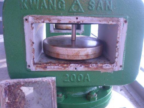
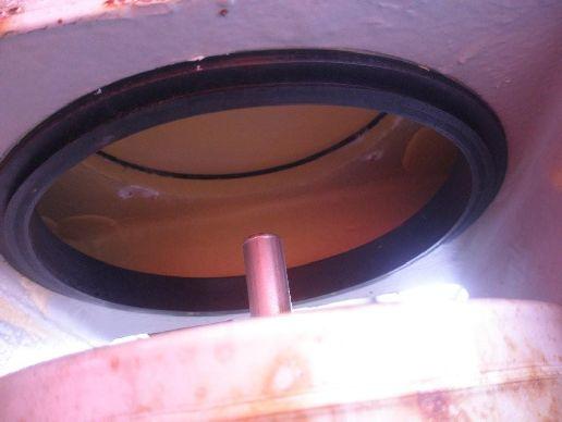
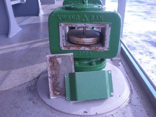
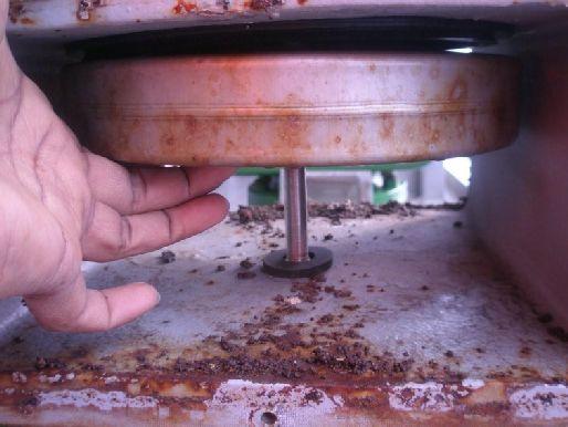
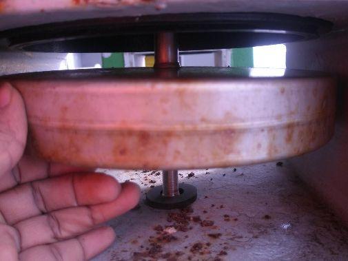
61 Q-explain the ventilation head of a DB tank Page 61
62 Ventilator head was designed in a way to prevent water passing in to tank from outside while ventilating the tank. Water will come out from the tank from the opening which place a rubber seal around it to sheet with the floater while it pressing upward. Maintenance 1-Check the Floater is freely moving up and down 2-Check the wire mesh for rust and breakages 3-check the rubber seal in good condition Rudders A rudder allows the ship to turn, simple plates have been superseded by plates welded to cast or fabricated frame. Rudders are hollow and so provide for some buoyancy. In order to minimise the risk of corrosion internal surfaces are provided with a protective coating and some are even filled with foam. A drain plug is provided to allow for the drainage of water, enable internal inspection to be made using fiber optic device and even allow for the limited application of a protective coating. Plates are welded to the frames internally in order to provide flush fitting, the final closing plate must be welded externally. A means of lifting is provided taking the form of a tube as close to the center of gravity as possible. Rudders are tested to a pressure head 2.4m above the top of the rudder. If the rudder has its entire area aft of the rudder stock then it is unbalanced.a rudder with between 20 and 40% of its area forward of the stock is balanced since there will be some angle at which the resultant moment on the stock due to the water force will be zero. Most modern rudders are of the semi-balanced design. This means that that a certain proportion of the water force acting on the after part of the rudder is counter acted by the force acting on the for'd half of the rudder; hence, the steering gear can be lighter and smaller. A rudder may lift due to the buoyancy effect, the amount of lift is limited by the jumper bar fitted to the stern frame. The jumper/rudder clearance must be less than the steering gear cross head clearance to prevent damage. A rudder is supported by means of a bearing pintle or a lower bearing depending upon the design. Where a lower bearing is employed the rudder is actually supported on split bearing rings fitted on the lower face of the rudder and the upper face of the sole piece ( the extended lower section of the stern frame upon which the rudder sits) SEMI BALANCED RUDDER Semi balanced rudder with rudder horn Page 62
63 Fully balanced rudder To reduce the amount of torque required to turn a rudder the pivot point is moved back from the leading edge. The amount of torque then varies depending on the angle of attack. Zero torque leads to instability with rudder moving within its clearances. Page 63
64 Spade Rudder The reduced diameter at the upper part is purely to transmit torque. The lower section must also support bending moments and hence increased diameter. With twin rudder ships the inner rudder must turn through a greater angle than the outer. This is achieved by having the tiller arm at an angle to the centre line of the rudder. It is possible to have the blades angled in or out when the wheel is amid ships to increase propulsive efficiency. Page 64
65 SPECIAL STEERING DEVICES THE KORT NOZZLE Adequate clearance is essential between propeller blade tips and sternframe in order to minimise the risk of vibration. As blades rotate water immediately ahead of the blades is compressed and at the blade tips this compression can be transmitted to the hull in the form of a series of pulses which set up vibration. Adequate clearance is necessary or alternatively constant clearance, this being provided with ducted propellers such as the Kort nozzle Originally designed to reduce erosion on river banks the nozzle has proved itself also able to increase thrust without increase of applied power. The nozzle consists of a ring of aerofoil section which forms a nozzle surrounding the propeller. The suction of the propeller causes an acceleration of flow in the mouth of the nozzle and hence a drop of pressure in this region. Since the pressure on the outer part of the nozzle remains relatively unchanged, there is a resulting differential in pressure, which acting on the projected annulus of the nozzle, gives the additional forward thrust. This additional thrust is transmitted direct from the kort nozzle to the hull via the nozzle supports,so that no additional force acts on the propeller and shaft thrust block. There are two types of Kort nozzles. The fixed type has a conventional rudder behind it, whereas with the swivelling rudder type, the whole assembly is supported by a carrier attached to the rudder stock and actuated by the steering gear. In the case of nozzle rudders,when helm is applied, the increased thrust has an athwartship component which has powerful steering effect, so that hard over angles of 25' ( or 30' in special cases ) are sufficient to provide effective steering ahead during a crash stop and,provided the hull is a reasonable design, astern. This device is especially valuable for tugs, trawlers, special vessels and more recently,vlcc, which are required to manoeuvre well, particularly at slow speed, and have the best propulsive efficiency. Page 65
66 Bollard pull gains between 30 and 50%, equivalent to re-engining up to 1 3/4 times the original power, have been obtained in tugs and trawlers and in VLCC gains in propulsive efficiency between 6 to 13% can be expected. The normal method of calculating rudder torque's can be applied to nozzle rudders. The maximum steering effort is required to return the rudder towards midships and not to move the rudder over from amidships. Thus, the steering gear must be designed to keep control of the rudder under these conditions. For diagram and additional notes see 'method of reducing vibration' and 'increasing propulsive efficiency' PLEUGER RUDDER A normal rudder can only be effective when the ship is moving, and the torque it exerts varies with the square of the speed,so that at very low speeds it can be very ineffective. A pleuger rudder incorporates a submersible electrically driven propeller which can be run when the main propulsion is at rest. In order to attain maximum effect and manoeuvre the ship at rest the rudder is able to turn to 90',owing to this normal floating linkage hunting gear cannot be used, and a special cam hunting gear used. For normal course keeping the angle is limited to 35',and a warning signal initiated if exceeded. THE VOITH SCHNEIDER PROPELLOR This propeller consists of a series of blades of aerofoil section which project vertically downwards from the ship's hull and rotate about a vertical axis. The blades are mounted on axes on a circle around the central axis and are linked together with a mechanism which can cause them to oscillate so as to provide thrust in any direction. The amount of thrust can be varied by varying the degree of oscillation, thus with the blade assembly rotating in the same direction, manipulation of the blades can give ahead or astern thrust, or port and starboard Page 66
67 thrust without an ahead or astern thrust component, or any angle of port or starboard thrust with ahead or astern thrust. The cycloid motion of the blades can be made to produce thrust in any direction round the circle of rotation. This means that the propeller in addition to providing the main drive for a ship provides full manoeuvrability without the need to provide a rudder and steering gear. This unusual degree of control is of particular value for special craft or floating equipment such as floating cranes or drilling ships which must be kept in position. The location of the propeller depends upon the particular application and it can be placed where the maximum desired effect can be achieved. JET FLAP RUDDER Another device which is being investigated at the N.P.L. is the jet flap rudder. In the trailing edge of an otherwise conventional rudder, a fluidic switch is fitted, which can direct a jet of water to port or starboard. The water is pumped into the hollow rudder through a hollow rudder stock. Considerable increase in manoeuvrability is claimed, especially at low speeds. Page 67
68 ROTATING CYLINDER RUDDERS This is a device to make a ship equally manoeuvrable at all speeds and was developed in the U.K by the Ship Division of the National Physical Laboratory (N.P.L.). A normal rudder is effective up to angles of about 35', after which the flow over the rudder stalls in a manner similar to that over an aeroplane wing at high angles of incidence. There are various methods of preventing this from occurring and they all involve feeding energy into the stream of fluid adjacent to the rudder or aerofoil surface. This is called boundary layer control. One such method is to rotate a cylinder at the leading edge of the section at such a speed that the rudder can be put over to 90' without stall, and this is the basic principle of operation of the rotating cylinder rudder. It is, of course, necessary to reverse the direction of rotation of the cylinder depending on whether the rudder is put to port or starboard, and such a system can be fitted to almost any type of rudder, balanced or unbalanced. The major advantage of putting a rudder over to such a high angle is that the flow from the main engines may be deflected through a much larger angle than with a conventional rudder, and static side thrusts of over 50 per cent of the bollard pull have been measured. Another main advantage is that its effect is independent of forward speed and it works as effectively at zero as at full speed. Page 68
69 Schilling Rudder Becker flap The flap is attached to the hull. As the rudder rotates the flap is turned in an same direction increasing the aerofoil shape and thereby increasing lift. This system can be used at very large rudder angles giving side thrust capabilities Page 69

70 This design allows for larger turning forces for the same sized rudder or reduced size requirements compared to other sizes Anouther format allows the flap to be steered independently. This again allows increases in thrust as well as improving steering with the vessel underway as only the flap has to be turned to cause small corrections to be carried out MANOEUVRABILITY AND STOPPING The problems of improving the manoeuvrability and braking of ships is of increasing importance as they increase in size. One device which is being tried out to improve stopping power is to arrange the control of twin rudders so that they move outboard simultaneously. This involves two separate steering gears, one for each rudder, the movement of which must be synchronised for normal steering. With twin rudder ships the inner rudder on a turn must turn through a greater angle than the outer. This is achieved by having the tiller arm at an angle to the center line of the rudder. It is also possible to slightly angle the rudders either in or out to increase propulsive efficiency. Page 70
.")

71 Propellers Blade Blade Back Suction side. Forward side of the blade (surface facing the bow). Blade Face Pressure Side, Pitch Side. Aft side of the blade (surface facing the stern). Blade Number Equal to the number of blades on the propeller. Blade Root Fillet area. The region of transition from the blade surfaces and edges to the hub periphery. The area where the blade attaches to the hub. Blade Tip Maximum reach of the blade from the center of the hub. Separates the leading and trailing edges. Page 71


72 Cavitations Cavitation, (which is often confused with ventilation), is a phenoma of water vaporizing or boiling due to the extreme reduction of pressure on the back of the propeller blade. Many propellers partially cavitate during normal operation, but excessive cavitation can result in physical damage to the propeller s blade surface due to the collapse of the microscopic bubbles on the blade. There may be numerous causes of cavitation such as incorrect matching of propeller style to application, incorrect pitch, physical damage to the blade edges, etc Cup Small radius of curvature located on the trailing edge of the blade. This curved lip on the propeller allows it to get a better bite in the water. This results in reduced vebtilation, slipping, and allows for a better hole shot in many cases. Page 72


73 Diameter Diameter is two times the distance from the center of the hub to the tip of the blade. It can also be looked at as the distance across the circle that the propeller would make when rotating. This is the first number listed when describing a propeller. Hub Solid cylinder located at the center of the propeller. Bored to accommodate the engine shaft. Hub shapes include cylindrical, conical, radius, & barreled. Leading Edge Page 73
74 The edge of the propeller blade adjacent to the forward end of the hub. When viewing the propeller from astern, this edge is furthest away. The leading edge leads into the flow when providing forward thrust. Non Thru hub exhaust Non thru-hub exhaust propellers are used for inboards using shaft driven propellers, sterndrives using through hull exhaust, and on some outboards that don t route the exhaust through the lower topedo. Over Hub Exhust Over-hub exhaust propellers have the blades attached directly to the smaller tube that fits over the propeller shaft, eliminating the larger exhaust tube. These types of propellers are often used for attaining maximum top speeds. (On some boats, the hole shot can suffer due to extreme exhuast flooding that occurs around the propeller blades during acceleration.) Page 74

75 Over/Thu Hub Exhaust Over/Thru-hub exhaust propellers are a combination of thru-hub and over-hub exhaust propellers. This allows some exhaust to escape at lower RPMs, providing a controlled amount of exhaust flooding. These types of propellers will allow the propeller to be slightly easier to turn during initial acceleration, allowing for a better hole shot on some engine/boat combinations. Pitch Pitch is defined as the theoretical forward movement of a propeller during one revolution assuming there is no slippage between the propeller blade and the water. Pitch is the second number listed in the propeller description. Page 75


76 Radius The distance from the axis of rotation to the blade tip. The radius multiplied by two is equal to the diameter Rake Rake is the degree that the blades slant forward or backwards in relation to the hub. Rake can affect the flow of water through the propeller, and as implications with respect to boat performance. Aft Rake helps to trim the bow of the boat upward, which often results in less wetted surface area and therefore higher top end speed. Forward, or negative rake, helps hold the bow of the boat down. This is more common in workboat type applications. Page 76

77 Rotation When viewed from the stern (facing forward): Right-hand propellers rotate clockwise to provide forward thrust. Left-hand propellers rotate counter-clockwise to provide forward thrust Trailing Edge The edge of the propeller adjacent to the aft end of the hub. When viewing the propeller from astern, this edge is closest. The trailing edge retreats from the flow when providing forward thrust. Controllable pitch propeller The propeller blades mount separately on the hub, each on an axis of rotation, allowing a change of pitch in the blades and thus the propeller. Fixed pitch propeller The propeller blades are permanently mounted and do not allow a chance in the propeller pitch Page 77


78 Constant Pitch Propeller The propeller blades have the same value of pitch from root to tip and from leading edge to trailing edge. The variable pitch propeller The propeller blades have sections designed with varying values of local face pitch on the pitch side or blade face. Thu hub exhaust Thru-hub exhaust propellers consist of a round barrel to which the blades are attached. The exhaust passes through the barrel and out the back, without making contact with the propeller blades. This provides a good, clean water flow to the blades, usually resulting in good acceleration and hole shot Skew The transverse sweeping of a blade such that viewing the blades from fore or aft shows an asymmetrical shape. Aft skew is positive skew, where blades sweep in the direction opposite of rotation. Forward skew is negative skew, where blades sweep in the same direction as rotation Page 78
79 Slip Slip is the difference between actual and theoretical travel of the propeller blades through water. A properly match propeller will actually move forward about 80 to 90 perfect of the theoretical pitch Ventilation A situation where surface air or exhaust gases are drawn into the propeller blades. When this situation occurs, boat speed is lost and engine RPMclimbs rapidly. This can result from excessively tight cornering, a motor that is mounted very high on the transom, or by overtrimming the engine Cylindrical Section A cross section of a blade cut by a circular cylinder whose centerline is the propeller axis of rotation. Pitch reference line Reference line used to establish the geometric pitch angle for the section. This line may pass through the leading and trailing edges of the section and may be equivalent to the chord line. Geometric pitch angle The angle between the pitch reference line and a line perpendicular to the propeller axis of rotation. Page 79

80 Track The absolute difference of the actual individual blade height distributions to the other blade height distributions. Always a positive value and represents the spread between the individual blade height distributions. WELDING SAFELY Welding hazards pose an unusual combination of safety and health risks. By its nature, welding produces fumes and noise, gives off radiation, involves electricity or gases, and has the potential for burns, shock, fire, and explosions. Some hazards are common to both electric arc and oxygen-fuel gas welding. If you work with or near a welding operation, the following general precautions should help you to work more safely. Weld only in designated areas. Only operate welding equipment you have been trained to use. Know what the substance is that s being welded and any coating on it. Wear protective clothing to cover all exposed areas of the body for protection sparks, hot spatter, and radiation. Protective clothing should be dry and free of holes, grease, oil, and other substances which may burn. Wear flameproof gauntlet gloves, a leather apron, and high-top shoes to provide good protection against sparks and spatter. Wear specifically designed, leak-proof helmets equipped with filter plates to protect against ultraviolet, infrared, and visible radiation. Never look at a flash, even for an instant. Keep your head away from the plume by staying back and to the side of the work. Use your helmet and head position to minimize fume inhalation in your breathing zone. Make sure there is good local exhaust ventilation to keep the air in your breathing zone clear. Don t weld in a confined space without adequate ventilation Don t weld in wet areas, wear wet or damp clothing or weld with wet hands. Page 80
81 Don t weld on containers which have held combustible materials or on drums, barrels or tanks until proper safety precautions have been taken to prevent explosions. If others are working in the area be sure they are warned and protected against arcs, fumes, sparks, and other welding hazards. Don t coil the electrode cable around your body. Ground both the frame of the welding equipment and metal being welded. Check for leaks in gas hoses using an inert gas. Check area around you before welding to be sure no flammable material or degreasing solvents are in the welding area. Keep a fire watch in the area during and after welding to be sure there are no smoldering materials, hot slag or live sparks which could start a fire. Locate the nearest fire extinguisher before welding. Deposit all scraps and electrode butts in proper waste container to avoid fire and toxic fumes. ALL QUESTIONS MUST BE ANSWERED TO PROCEED 1. Is the area clean and clear of oil and other dangerous material 2. Is the area free of all flammable debris and scale 3. Are adjacent areas/compartments, cleaned, gas free 4. Have all potential sources of flammable vapours that could reach the site of hot work been prevented from doing so 5. To assure that combustibles will not reach the work site, have winds and air current been considered 6. Has the area to be worked on been thoroughly ventilated and continuos ventilation available 7. Is the oxygen content of work area > 20% but 21% 8. If work is being carried out inside a tank has it been tested for hydrocarbon vapours and less than 1% LFL 9. If the work area is a fuel pipe, has it been disconnected from the surrounding pipe and thoroughly flushed 10. Has a fire watch been set up with appropriate fire fighting equipment 11. Have instructions and plans been discussed in case of an emergency 12. Is the fire main charged, hoses let out and ready for use 13.a) If welding, has the welding machine been properly grounded b) Has Item / Piece being welded properly grounded. 14. Has the hot work equipment been inspected prior to starting work and found in good order 15. Have personnel been provided with proper Personal Protective Equipment 16. If working in enclosed space has the Enclosed Space Entry form been filled in Page 81

82 Page 82
OPERATIONS SEAFARER CERTIFICATION GUIDANCE NOTE SA MARITIME QUALIFICATIONS CODE
 Page 1 of 8 Compiled by Chief Examiner Approved by Qualifications Committee: 27 September 2013 OPERATIONS SEAFARER CERTIFICATION GUIDANCE NOTE SA MARITIME QUALIFICATIONS CODE Page 2 of 8 KNOWLEDGE, UNDERSTANDING
SECOND ENGINEER REG III/2 NAVAL ARCHITECTURE
 SECOND ENGINEER REG III/2 NAVAL ARCHITECTURE LIST OF TOPICS A B C D E F G H I J Hydrostatics Simpson's Rule Ship Stability Ship Resistance Admiralty Coefficients Fuel Consumption Ship Terminology Ship
STRUCTURAL MEMBERS OF A SHIP. compartment stem frame beam bracket girder stern post hull angle bar stiffener
 Unit 2 SHIPS AND SHIPS TERMS STRUCTURAL MEMBERS OF A SHIP Basic terms shell plating strake keel deck tank top floor stringer buoyancy strength stability bulkhead compartment stem frame beam bracket girder
PASSENGER SHIPS Guidelines for preparation of Hull Structural Surveys
 (Feb 2010) PASSENGER SHIPS Guidelines for preparation of Hull Structural Surveys Contents 1 Introduction 2 Preparations for Survey 2.1 General 2.2 Conditions for survey 2.3 Access to structures 2.4 Survey
Marine Construction & Welding Prof. Dr. N. R. Mandal Department of Ocean Engineering & Naval Architecture Indian Institute of Technology, Kharagpur
 Marine Construction & Welding Prof. Dr. N. R. Mandal Department of Ocean Engineering & Naval Architecture Indian Institute of Technology, Kharagpur Lecture No # 10 Fore & Aft End Construction (Refer Slide
AMENDMENTS NO. 2/2012 to
 RULES AMENDMENTS NO. 2/2012 to PUBLICATION NO. 84/P REQUIREMENTS CONCERNING THE CONSTRUCTION AND STRENGTH OF THE HULL AND HULL EQUIPMENT OF SEA-GOING BULK CARRIERS OF 90 M IN LENGTH AND ABOVE 2009 GDAŃSK
The following Rule Changes were approved by the ABS Rules Committee on 1 June 2018 and
 RULES FOR SURVEY AFTER CONSTRUCTION 2018 NOTICE NO. 2 July 2018 The following Rule Changes were approved by the ABS Rules Committee on 1 June 2018 and become EFFECTIVE AS OF 1 JULY 2018. (See http://www.eagle.org
PART 3 HULL INTEGRITY AND ARRANGEMENT
 PART 3 HULL INTEGRITY AND ARRANGEMENT PART 3 HULL INTEGRITY AND ARRANGEMENT SECTION SUBJECT 3.1 Doors, hatchways, and coamings 3.2 Air pipes 3.3 Ventilators 3.4 Portlights 3.5 Skylights 3.6 Windows 3.7
SHIP FORM DEFINITION The Shape of a Ship
 SHIP FORM DEFINITION The Shape of a Ship The Traditional Way to Represent the Hull Form A ship's hull is a very complicated three dimensional shape. With few exceptions an equation cannot be written that
PART 3 HULL INTEGRITY AND ARRANGEMENT
 PART 3 HULL INTEGRITY AND ARRANGEMENT PART 3 HULL INTEGRITY AND ARRANGEMENT SECTION SUBJECT 3.1 General 3.2 Doors, hatchways and covers 3.3 Air pipes 3.4 Ventilators 3.5 Side scuttles (portholes) and
Part 3 Hull Chapter 2 General arrangement design
 RULES FOR CLASSIFICATION Yachts Edition October 2016 Part 3 Hull Chapter 2 The content of this service document is the subject of intellectual property rights reserved by ("DNV GL"). The user accepts that
The salient features of the 27m Ocean Shuttle Catamaran Hull Designs
 The salient features of the 27m Ocean Shuttle Catamaran Hull Designs The hull form is a semi-planing type catamaran. It employs a combination of symmetrical and asymmetrical sponson shapes, thereby combining
STEEL VESSELS 2014 RULES FOR BUILDING AND CLASSING PART 3 HULL CONSTRUCTION AND EQUIPMENT. (Updated July 2014 see next page)
") Part 3: Hull Construction and Equipment RULES FOR BUILDING AND CLASSING STEEL VESSELS 2014 PART 3 HULL CONSTRUCTION AND EQUIPMENT (Updated July 2014 see next page) American Bureau of Shipping Incorporated
Part 3: Hull Construction and Equipment RULES FOR BUILDING AND CLASSING STEEL VESSELS 2014 PART 3 HULL CONSTRUCTION AND EQUIPMENT (Updated July 2014 see next page) American Bureau of Shipping Incorporated
TP 11249E SHIP SAFETY STANDARD FOR IN-WATER SURVEYS
 TP 11249E SHIP SAFETY STANDARD FOR IN-WATER SURVEYS Canadian Coast Guard Ship Safety Branch 1992 TP 11249E RECORD OF CHANGES STANDARD FOR IN WATER SURVEYS DATE OF AMENDMENT AMENDMENT NUMBER SECTION AMENDED
ANNEX 5 IMO MARINE CASULATY AND INCIDENT REPORT DAMAGE CARDS* AND INTACT STABILITY CASUALTY RECORDS
 ANNEX 5 IMO MARINE CASUATY AND INCIDENT REPORT DAMAGE CARDS* AND INTACT STABIITY CASUATY RECORDS Statistics of damaged ships and of intact stability casualties are important to the work of the Organization
PART 1 GENERAL REQUIREMENTS
 PART 1 GENERAL REQUIREMENTS SECTION SUBJECT 1.1 Standards 1.2 Compliance procedures and certification 1.3 Building premises 1.4 Testing of structures 1.5 Materials 1.6 Definitions of expressions GENERAL
RULES PUBLICATION NO. 20/P SHIP SIDE STRENGTHENING OF FISHING VESSELS MOORING AT SEA ALONGSIDE OTHER VESSELS
 RULES PUBLICATION NO. 20/P SHIP SIDE STRENGTHENING OF FISHING VESSELS MOORING AT SEA ALONGSIDE OTHER VESSELS 1995 Publications P (Additional Rule Requirements), issued by Polski Rejestr Statków, complete
Marine Kit 4 Marine Kit 4 Sail Smooth, Sail Safe
 Marine Kit 4 Marine Kit 4 Sail Smooth, Sail Safe Includes Basic ship Terminologies and Investigation Check list Index 1. Ship Terminology 03 2. Motions of a Floating Body...09 3. Ship Stability.10 4. Free
Abstract. 1 Introduction
 Buoyancy and strength of existing bulk carriers in flooded conditions J. Jankowski, M. Bogdaniuk, T. Dobrosielski Polski Rejestr Statkow, Gdansk, Poland Email: tk@prs.gda.pl Abstract Bulk carriers have
Part 3 Structures, equipment Chapter 1 Hull design and construction, general
 RULES FOR CLASSIFICATION Inland navigation vessels Edition December 2015 Part 3 Structures, equipment Chapter 1 Hull design and construction, general The content of this service document is the subject
SCANTLING AND EQUIPMENT TABLES (STEEL AND ALUMINIUM ALLOY)
") PART 6 SCANTLING AND EQUIPMENT TABLES (STEEL AND ALUMINIUM ALLOY) SECTION SUBJECT 6.1 Scantling nueral diensions for steel onohull vessels 6.2 Keel and ste 6.3 Stern frae 6.4 Shell plating 6.5 Transverse
PART 6 SCANTLING AND EQUIPMENT TABLES (STEEL AND ALUMINIUM ALLOY) SECTION SUBJECT 6.1 Scantling nueral diensions for steel onohull vessels 6.2 Keel and ste 6.3 Stern frae 6.4 Shell plating 6.5 Transverse
RULES FOR THE CONSTRUCTION AND CLASSIFICATION OF SHIPS IDENTIFIED BY THEIR MISSIONS CHAPTERS SCOPE
 PART II RULES FOR THE CONSTRUCTION AND CLASSIFICATION OF SHIPS IDENTIFIED BY THEIR MISSIONS TITLE 12 CONTAINER SHIPS SECTION 2 STRUCTURES CHAPTERS A B C SCOPE DOCUMENTS, REGULATIONS AND STANDARDS See Part
A1.1.5 It is assumed that under normal circumstances a ship uses only one bow anchor and chain cable at a time.
 (1981) (Rev.1 1987) (Rev.2 1992) (Rev.3 1994) (Rev.4 Aug 1999) (Rev.5 Jun 2005) (Rev.6 Oct 2016) (Corr.1 Dec 2016) (Corr.2 Mar 2017) Anchoring Equipment.1 Design of the anchoring equipment.1.1 The anchoring
PRIMARY EDUCATION PACK SHIP TERMS
 PRIMARY EDUCATION PACK SHIP TERMS www.titanclydebank.com Ship Terms and Definitions A Aft Toward, at, or near stern. After Nearer stern. Aftermost Nearest the stern. Air Port A circular opening or window
RULES FOR CLASSIFICATION OF MOBILE OFFSHORE UNITS
 CHINA CLASSIFICATION SOCIETYY Rule Change Notice For: RULES FOR CLASSIFICATION OF MOBILE OFFSHORE UNIT S 2012 Version: December, 2015,RCN No.1 Effective date: 1 January, 20162 Beijing Contents PART ONE
Ship Resistance and Propulsion Prof. Dr. P. Krishnankutty Ocean Department Indian Institute of Technology, Madras
 Ship Resistance and Propulsion Prof. Dr. P. Krishnankutty Ocean Department Indian Institute of Technology, Madras Lecture - 6 Bulbous Bow on Ship Resistance Welcome back to the class we have been discussing
Parts of the Ship. Terms you should already know
 Parts of the Ship Toronto Brigantine Terms you should already know After-peak Fore-peak Bow Stern Fairlead Scupper Freeing port Hull Deck Lifeline Hatch Skylight Cleat Pin-rail Fife-rail Spider-band Block
Testing Procedures of Watertight Compartments
 (1996) (Rev.1 Feb 2001) (Rev.2 May 2001) (Rev.3 May 2010) (Rev.4 Aug 2012) Testing Procedures of Watertight Compartments.1 Application Revision 4 of this UR is to be complied with in respect of the testing
Definitions 13 FREE SURFACE EFFECT
 Definitions 13 FREE SURFACE EFFECT When a vessel with a full tank is heeled, the liquid within the tank acts like a solid mass. Its centre of gravity, being the centre of its volume, remains constant and
Development of TEU Type Mega Container Carrier
 Development of 8 700 TEU Type Mega Container Carrier SAKAGUCHI Katsunori : P. E. Jp, Manager, Ship & Offshore Basic Design Department, IHI Marine United Inc. TOYODA Masanobu : P. E, Jp, Ship & Offshore
Anchor and Anchor Cable Losses. Athens, Greece, 2 nd February 2018 Capt. Simon Rapley
 Anchor and Anchor Cable Losses Athens, Greece, 2 nd February 2018 Capt. Simon Rapley Anchor Loses Items lost: Whole anchors Anchor crowns Anchor and shackles of cable Anchor and entire anchor cable Shank
TECHNICAL CIRCULAR. Circular No: S-P 32/13 Revision: 1 Page: 1 of 7 Date:
 Circular No: S-P 32/13 Revision: 1 Page: 1 of 7 Date:22.05.2014 Related Requirement: UR S27 (Rev.6 June 2013) Subject: Retroactive Application for Strength Requirements for Fore Deck Fittings and Equipment
CLIENT NAME: LOCATION: CALM BUOY INSPECTION:
 INSPECTOR REVIEWED INSPECTION OF CALM BUOY OVERALL PHOTO REVISION DESCRIPTION: Preliminary / Final Page: 1 TABLE OF CONTENT 1. MANAGEMENT SUMMARY... 3 1.1. SCOPE OF WORK:... 3 1.2. CORRECTIVE ACTIONS...
RESOLUTION MSC.235(82) (adopted on 1 December 2006) ADOPTION OF THE GUIDELINES FOR THE DESIGN AND CONSTRUCTION OF OFFSHORE SUPPLY VESSELS, 2006
 (adopted on 1 December 2006) ADOPTION OF THE GUIDELINES FOR THE DESIGN AND CONSTRUCTION OF OFFSHORE SUPPLY VESSELS, 2006") MSC 82/24/Add.2 RESOLUTION MSC.235(82) CONSTRUCTION OF OFFSHORE SUPPLY VESSELS, 2006 THE MARITIME SAFETY COMMITTEE, RECALLING Article 28(b) of the Convention on the International Maritime Organization
MSC 82/24/Add.2 RESOLUTION MSC.235(82) CONSTRUCTION OF OFFSHORE SUPPLY VESSELS, 2006 THE MARITIME SAFETY COMMITTEE, RECALLING Article 28(b) of the Convention on the International Maritime Organization
Ship knowledge questions
 Part 1 Ship knowledge questions 1. In the following sketch, label the parts indicated by ( ). 2. In the following sketch, label the parts indicated by ( ). 3. In the following sketch, label the indicated
ITTC Recommended Procedures and Guidelines
 7.5- -- Page 1 of 6 Table of Contents 1 PURPOSE OF PROCEDURE 2 2 PARAMETERS...2 2.1 Definition of Variables...2 3 DESCRIPTION OF PROCEDURE...2 3.1...2 3.1.1 Hull Model...2 3.1.2 Propeller Model...3 3.1.3
MSC Guidelines for Engine Cooling Systems
 S. T. Brady, CDR, Chief, Engineering Division References: Contact Information: a. 46 CFR 56.60, 56.50-95 & 56.50-96 (Subchapter F) b. 46 CFR 77.03-1 (Subchapter H) c. 46 CFR 90.20 & 46 CFR 96.03 (Subchapter
Vessel Modification and Hull Maintenance Considerations Options & Pay Back Period or Return On Investments
 Vessel Modification and Hull Maintenance Considerations Options & Pay Back Period or Return On Investments By Dag Friis Christian Knapp Bob McGrath Ocean Engineering Research Centre MUN Engineering 1 Overview:
CERTIFICATES OF COMPETENCY IN THE MERCHANT NAVY MARINE ENGINEER OFFICER
 CERTIFICATES OF COMPETENCY IN THE MERCHANT NAVY MARINE ENGINEER OFFICER EXAMINATIONS ADMINISTERED BY THE SCOTTISH QUALIFICATIONS AUTHORITY ON BEHALF OF THE MARITIME AND COASTGUARD AGENCY STCW 95 CHIEF
MSC Guidelines for Vents, Fills and Sounds
 S. J. Kelly, CDR, Chief of Engineering Division References: a. 46 CFR 56.50-85 & 56.50-90 (Subchapter F) b. 46 CFR 32.55, 36.20-1 & 38.20 (Subchapter D) c. 46 CFR 119.445 & 119.450 (Subchapter K) d. 46
Specification of Dafman Patrol Boat 13.6
 YACHTS Page 1 of 10 A. PURPOSE: YACHTS This yacht is mainly responsible for the coastal anti-smuggling, patrolling and high speed chasing, which can be also used for the job of protecting and guarding
REGULATION on life boats operated from land, No 123/1999 CHAPTER I. General provisions Article 1
 REGULATION on life boats operated from land, No 123/1999 CHAPTER I General provisions Article 1 Scope These rules apply to lifeboats, the construction of which has begun or which have arrived in the country
Where: moulded displacement, in tonnes, as defined in Section 4/ B moulded breadth, in m, as defined in Section 4/1.1.3.
 SECTION 11 - GENERAL REQUIREMENTS COMMON STRUCTURAL RULES FOR OIL TANKERS 4 EQUIPMENT 4.1 Equipment Number Calculation 4.1.1 Requirements 4.1.1.1 Anchors and chains are to be in accordance with Table 11.4.1
Special Considerations for Structural design and Fabrication for. tankers or similar vessels with Large Size (150m or more in length) in.
 in.") Special Considerations for Structural design and Fabrication for tankers or similar vessels with Large Size (150m or more in length) in polar waters He. Guangwei Guangwei_ho@chinagsi.com Mai. Rongzhi MRZ@chinagsi.com
Special Considerations for Structural design and Fabrication for tankers or similar vessels with Large Size (150m or more in length) in polar waters He. Guangwei Guangwei_ho@chinagsi.com Mai. Rongzhi MRZ@chinagsi.com
Hatch cover securing and tightness
 (1986) (Rev 1 1996) (Corr.1 June 2000) (Rev.2 July 2005) (Corr.1 Oct 2005) Hatch cover securing and tightness 1. Application 1.1 The following recommendations apply to steel hatch covers that are fitted
Numerical Modelling Of Strength For Hull Form Components Of A 700 Tonne Self-Propelled Barge Under Moment And Operational Loading
 IOSR Journal of Engineering (IOSRJEN) ISSN (e): 2250-3021, ISSN (p): 2278-8719 Vol. 05, Issue 05 (May. 2015), V1 PP 45-55 www.iosrjen.org Numerical Modelling Of Strength For Hull Form Components Of A 700
Aidan Tuckett B.Sc.(Hons).
.") 1 of 11 Aidan Tuckett B.Sc.(Hons). MARINE SURVEYOR Accredited Member of the Yacht Designers and Surveyors Association REPORT OF A CONDITION SURVEY CARRIED OUT ON THE VESSEL: xxxxxxxxxxxxx 2 of 11 CONTENTS.
1 of 11 Aidan Tuckett B.Sc.(Hons). MARINE SURVEYOR Accredited Member of the Yacht Designers and Surveyors Association REPORT OF A CONDITION SURVEY CARRIED OUT ON THE VESSEL: xxxxxxxxxxxxx 2 of 11 CONTENTS.
THE OWNER'S MANUAL IS IN TWO VOLUMES: VOLUME 2 TECHNICAL SPECIFICATIONS - ASSEMBLY PROCEDURE ZODIAC
 CAUTION NOTICE: CAREFULLY READ THIS MANUAL BEFORE OPERATING YOUR BOAT. THIS OWNER S MANUAL IS IN TWO VOLUMES THAT MUST BE KEPT TOGETHER. THE OWNER'S MANUAL IS IN TWO VOLUMES: - VOLUME 1 DEALS WITH OPERATING
Periodical surveys of cargo installations on ships carrying liquefied gases in bulk
 (June 1999) (Rev.1 Mar 2006) (Rev.2 May 2007) (Rev.3 Mar 2010) (Corr.1 Feb 2011) (Rev.4 Oct 2013) Periodical surveys of cargo installations on ships carrying liquefied gases in bulk 1 General 1.1 Scope
MSC Guidelines for Review of Stability for Sailing Catamaran Small Passenger Vessels (T)
") K.B. FERRIE, CDR, Chief, Hull Division References: a. 46 CFR Subchapter T, Parts 178, 179 b. 46 CFR Subchapter S, Parts 170, 171 c. Marine Safety Manual (MSM), Vol. IV d. Navigation and Vessel Circular
K.B. FERRIE, CDR, Chief, Hull Division References: a. 46 CFR Subchapter T, Parts 178, 179 b. 46 CFR Subchapter S, Parts 170, 171 c. Marine Safety Manual (MSM), Vol. IV d. Navigation and Vessel Circular
RESOLUTION MSC.143(77) (adopted on 5 June 2003) AMENDMENTS TO THE PROTOCOL OF 1988 RELATING TO THE INTERNATIONAL CONVENTION ON LOAD LINES, 1966
 (adopted on 5 June 2003) AMENDMENTS TO THE PROTOCOL OF 1988 RELATING TO THE INTERNATIONAL CONVENTION ON LOAD LINES, 1966") RESOLUTION MSC.143(77) AMENDMENTS TO THE PROTOCOL OF 1988 RELATING TO THE INTERNATIONAL CONVENTION ON LOAD LINES, 1966 THE MARITIME SAFETY COMMITTEE, RECALLING Article 28(b) of the Convention on the International
RESOLUTION MSC.143(77) AMENDMENTS TO THE PROTOCOL OF 1988 RELATING TO THE INTERNATIONAL CONVENTION ON LOAD LINES, 1966 THE MARITIME SAFETY COMMITTEE, RECALLING Article 28(b) of the Convention on the International
BASIC AIRCRAFT STRUCTURES
 Slide 1 BASIC AIRCRAFT STRUCTURES The basic aircraft structure serves multiple purposes. Such as aircraft aerodynamics; which indicates how smooth the aircraft flies thru the air (The Skelton of the aircraft
Chapter 1 Boat systems
 Chapter 1 Boat systems Hulls Two common types of boating hulls, displacement and planing, are shown in Figure 5.1. A displacement hull is a type of hull that ploughs through the water, displacing a weight
Policy for the Implementation of International Load Lines
 IDEPARTMENT OF MARINE ADMIN STRATION MYANMAR Department of Marine Administration - Yangon Myanmar Policy for the Implementation of International Load Lines Operational Procedure : QOP - 72-01- (05) Revision:
Testing Procedures of Watertight Compartments
 (1996) (Rev.1 Feb 2001) (Rev.2 May 2001) (Rev.3 May 2010) (Rev.4 Aug 2012) (Rev.5 Jan 2015) (Rev.6 Sept 2016) Testing Procedures of Watertight Compartments.1 Application Revision 6 of this UR is to be
Dr. Konstantinos Galanis
 Dr. Konstantinos Galanis Operations & Technical Senior Manager Seanergy Maritime Holdings Corp. Thorough basic knowledge of shipbroking Commodities, carriage requirements, vessels Charterers, shipowners,
Testing Procedures of Watertight Compartments
 (1996) (Rev.1 Feb 2001) (Rev.2 May 2001) (Rev.3 May 2010) (Rev.4 Aug 2012) (Rev.5 Jan 2015) Testing Procedures of Watertight Compartments.1 Application Revision 45 of this UR is to be complied with in
MSC Guidelines for Review of General Arrangement Plans for Small Passenger Vessels (T)
") S. E. Hemann, CDR, Chief, Hull Division References a. 46 CFR Subchapter T, Part 177, 178, & 179 b. Marine Safety Manual (MSM) Vols. II & IV c. 21 CFR Subchapter L, Part 1250 Contact Information If you
S. E. Hemann, CDR, Chief, Hull Division References a. 46 CFR Subchapter T, Part 177, 178, & 179 b. Marine Safety Manual (MSM) Vols. II & IV c. 21 CFR Subchapter L, Part 1250 Contact Information If you
Guide for Assessing Hull-Girder Residual Strength for Tankers. July 1995
 AMERICAN BUREAU OF SHIPPING 8, AFFILIATED COMPANIES Guide for Assessing Hull-Girder Residual Strength for Tankers July 1995 American Bureau of Shipping Incorporated by the Legislature of the State of New
Sprocket Selection Guidelines
 Sprocket Selection Guidelines Table 1 Information Necessary to Order Sprockets 1. Chain Size Number, type, or drawing number of the chain to be used on the sprocket. (The suitability of a sprocket depends
Doors in watertight bulkheads of cargo ships and passenger ships
 (June 2002) (Rev.1 Oct 2018) Doors in watertight bulkheads of cargo ships and passenger ships Application This unified interpretation pertains to doors 1 located in way of the internal watertight subdivision
Planning and general precautions ithrust Tunnel Systems installations.
 Version 1.0 This recommendation will go through the different factors to consider when choosing where and how to fit thruster tunnels in a boat. Some of these recommendations might be difficult, or even
FISHING VESSELS SHIPS RULES FOR CLASSIFICATION OF NEWBUILDINGS DET NORSKE VERITAS SPECIAL SERVICE AND TYPE ADDITIONAL CLASS PART 5 CHAPTER 6 JULY 1995
 RULES FOR CLASSIFICATION OF SHIPS NEWBUILDINGS SPECIAL SERVICE AND TYPE ADDITIONAL CLASS PART 5 CHAPTER 6 FISHING VESSELS JULY 1995 CONTENTS PAGE Sec. 1 General Requirements... 5 Sec. 2 Design Requirements...
RESOLUTION MSC.141(76) (adopted on 5 December 2002) REVISED MODEL TEST METHOD UNDER RESOLUTION 14 OF THE 1995 SOLAS CONFERENCE
 (adopted on 5 December 2002) REVISED MODEL TEST METHOD UNDER RESOLUTION 14 OF THE 1995 SOLAS CONFERENCE") MSC 76/23/Add.1 RESOLUTION MSC.141(76) THE MARITIME SAFETY COMMITTEE, RECALLING Article 38(c) of the Convention on the International Maritime Organization concerning the functions of the Committee, RECALLING
MSC 76/23/Add.1 RESOLUTION MSC.141(76) THE MARITIME SAFETY COMMITTEE, RECALLING Article 38(c) of the Convention on the International Maritime Organization concerning the functions of the Committee, RECALLING
RULES FOR THE CLASSIFFICATION OF SHIPS
 RULES FOR THE CLASSIFFICATION OF SHIPS Part - HULL CROATIAN REGISTER OF SHIPPING Hrvatska (Croatia) 1000 Split Marasovićeva 67 P.O.B. 187 Tel.: (...) 385 (0)1 40 81 11 Fax.: (...) 385 (0)1 35 81 59 E-mail:
National Marine Manufacturers Association
 1. All of the following would be considered as a compliant seacock except a. an in-line ball valve with a lever type handle operating through a 180 arc b. a flanged sea valve which mounts directly to the
OPENINGS AND REINFORCEMENTS 26
 ASME BPVC.VIII.1-2015 UG-35.2 UG-36 (4) It is recognized that it is impractical to write requirements to cover the multiplicity of devices used for quick access, or to prevent negligent operation or the
RULES FOR CLASSIFICATION Ships. Part 3 Hull Chapter 5 Hull girder strength. Edition October 2015 DNV GL AS
 RULES FOR CLASSIFICATION Ships Edition October 2015 Part 3 Hull Chapter 5 The content of this service document is the subject of intellectual property rights reserved by ("DNV GL"). The user accepts that
MANOEUVRING BOOKLET V1.06
 MANOEUVRING BOOKLET V1.6 Mathematical model of Integrated Tug Barge 45 Version: v9 Dll Version: 2.31.558 According to: Solas II-1, regulation 28.3 St. Petersburg 26 1. GENERAL DESCRIPTION 1.1. Ships particulars
RULES FOR CONSTRUCTION OF YACHTS
 CHINA CLASSIFICATION SOCIETY RULES FOR CONSTRUCTION OF YACHTS 2008 Effective from August 1 2008 Beijing CONTENTS CHAPTER 1 GENERAL...1 Section 1 GENERAL PROVISIONS...1 Section 2 COMPLIANCE SURVEY...2 CHAPTER
SHIPS FOR NAVIGATION IN ICE
 RULES FOR CLASSIFICATION OF SHIPS NEWBUILDINGS SPECIAL SERVICE AND TYPE ADDITIONAL CLASS PART 5 CHAPTER 1 SHIPS FOR NAVIGATION IN ICE JULY 2007 CONTENTS PAGE Sec. 1 General Requirements... 5 Sec. 2 Basic
FISHING VESSELS SHIPS RULES FOR CLASSIFICATION OF NEWBUILDINGS DET NORSKE VERITAS SPECIAL SERVICE AND TYPE ADDITIONAL CLASS PART 5 CHAPTER 6
 RULES FOR CLASSIFICATION OF SHIPS NEWBUILDINGS SPECIAL SERVICE AND TYPE ADDITIONAL CLASS PART 5 CHAPTER 6 FISHING VESSELS JANUARY 2003 This booklet includes the relevant amendments and corrections shown
Part 7 Fleet in service Chapter 2 Inclining test and light weight check
 RULES FOR CLASSIFICATION Inland navigation vessels Edition December 2015 Part 7 Fleet in service Chapter 2 Inclining test and light weight check The content of this service document is the subject of intellectual
INTERNATIONAL FLYING FIFTEEN CLASS MEASUREMENT FORM
 INTERNATIONAL FLYING FIFTEEN CLASS MEASUREMENT FORM 2014 Authority: * International Sailing Federation, Ariadne House, Town Quay, Southampton, Hampshire, SO14 2AQ, UK IN ORDER TO OBTAIN A MEASUREMENT CERTIFICATE
National Maritime Center
 National Maritime Center Providing Credentials to Mariners (Sample Examination) Page 1 of 16 Choose the best answer to the following Multiple Choice Questions. 1. Which term applies to the angle between
SHIPS FOR NAVIGATION IN ICE
 RULES FOR CLASSIFICATION OF SHIPS NEWBUILDINGS SPECIAL SERVICE AND TYPE ADDITIONAL CLASS PART 5 CHAPTER 1 SHIPS FOR NAVIGATION IN ICE JANUARY 2003 CONTENTS PAGE Sec. 1 General Requirements... 5 Sec. 2
Boat Boat Loader Fitting Instructions
 Aerodynamic & Heavy Duty Roof Rack Systems Australian Made - Australian Owned www.rhinorack.com Boat Boat Loader Fitting Instructions CONTROLLED Balance point 3 Front eye nuts position 3 Transom eye nut
International Ship Classification
 International Ship Classification To : All Offices From : General Manager ISClass Date : 11 November 2005 Ref : CIR05/0014 RE: INTERNATIONAL CONVENTION ON LOAD LINE, 1996 RECORDS OF CONDITIONS OF ASSIGNMENT
Part 3 Structures, equipment Chapter 1 Design principles, design loads
 RULES FOR CLASSIFICATION High speed and light craft Edition December 2015 Part 3 Structures, equipment Chapter 1 The content of this service document is the subject of intellectual property rights reserved
OPERATIONS SEAFARER CERTIFICATION GUIDANCE NOTE SA MARITIME QUALIFICATIONS CODE. Naval Architecture
 Page 1 of 27 Compiled by Approved by Chief Examiner Syllabus Committee: 26 July 2013 OPERATIONS SEAFARER CERTIFICATION GUIDANCE NOTE SA MARITIME QUALIFICATIONS CODE Page 2 of 27 KNOWLEDGE, UNDERSTANDING
Hydrostatics and Stability Dr. Hari V Warrior Department of Ocean Engineering and Naval Architecture Indian Institute of Technology, Kharagpur
 Hydrostatics and Stability Dr. Hari V Warrior Department of Ocean Engineering and Naval Architecture Indian Institute of Technology, Kharagpur Module No.# 01 Lecture No. # 01 Introduction Hello everybody.
Lecture 10 : Sewer Appurtenances
 1 P age Module 8 : Sewer Appurtenances Lecture 10 : Sewer Appurtenances 2 P age The structures, which are constructed at suitable intervals along the sewerage system to help its efficient operation and
FISHING VESSELS SHIPS RULES FOR CLASSIFICATION OF NEWBUILDINGS DET NORSKE VERITAS SPECIAL SERVICE AND TYPE ADDITIONAL CLASS PART 5 CHAPTER 6
 RULES FOR CLASSIFICATION OF SHIPS NEWBUILDINGS SPECIAL SERVICE AND TYPE ADDITIONAL CLASS PART 5 CHAPTER 6 FISHING VESSELS JANUARY 2011 CONTENTS PAGE Sec. 1 General Requirements... 6 Sec. 2 Design Requirements...
S/Y MORSKI ZEKAN TECHNICAL INFORMATION
 S/Y MORSKI ZEKAN TECHNICAL INFORMATION Cabins: 3 Toilets: 1 Max. Persons: 8 (6+2) LOA: 11,35 m Beam: 3,80 m Draft: 1,95 m Engine: Volvo 28HP Water tanks: 360 L Fuel tank: 150 L Anchor windlass Speed and
ANNEX 2 RESOLUTION MEPC.124(53) Adopted on 22 July 2005 GUIDELINES FOR BALLAST WATER EXCHANGE (G6) THE MARINE ENVIRONMENT PROTECTION COMMITTEE,
 Adopted on 22 July 2005 GUIDELINES FOR BALLAST WATER EXCHANGE (G6) THE MARINE ENVIRONMENT PROTECTION COMMITTEE,") Page 1 RESOLUTION MEPC.124(53) Adopted on 22 July 2005 GUIDELINES FOR BALLAST WATER EXCHANGE (G6) THE MARINE ENVIRONMENT PROTECTION COMMITTEE, RECALLING Article 38(a) of the Convention on the International
Page 1 RESOLUTION MEPC.124(53) Adopted on 22 July 2005 GUIDELINES FOR BALLAST WATER EXCHANGE (G6) THE MARINE ENVIRONMENT PROTECTION COMMITTEE, RECALLING Article 38(a) of the Convention on the International
CAISSON SHAFT SYSTEM
 CAISSON SHAFT SYSTEM Installation Guide INSTALLATION GUIDE FOR DN2000 TO DN3660 UNITS PLATE JOINTING SYSTEM This guide is to be used for the Installation of CPM Group Ltd caisson shaft units which use
Challenges in Ship Design to Maintain Thrusters inside Ship
 DYNAMIC POSITIONING CONFERENCE October 9-10, 2012 Thrusters Challenges in Ship Design to Maintain Thrusters inside Ship Tom Nylund and Timo Rintala Beacon Finland 1 DP Conference - Challenges in Ship Design
SERIES: "FALCON" MODELS: F400, F450, F500. User's manual
 SERIES: "FALCON" 2383.01-2004 MODELS: F400, F450, F500 Design category (94/25/EC): C ISO6185-3: Category VII User's manual PURPOSE The inflatable motor boat of the "FALCON" series relates to the category
BoatWasher Swede, , MS Float
 BoatWasher Swede, 400-600, MS Float Cleans the hull from algea, barnacles and other fouling. Cleans both motor- and sailing yachts. Three sizes of washers fits most boat types, up to approximate 25-meter
CHAPTER II-1 B. Construction subdivision and stability, machinery and electrical installations
 Only the Danish version is authentic Notice D II-1 B 1 October 2002 Technical regulation on the construction and equipment, etc. of passenger ships on domestic voyages CHAPTER II-1 B Construction subdivision
RULES FOR CONSTRUCTION AND CLASSIFICATION OF YACHTS
 CHINA CLASSIFICATION SOCIETY RULES FOR CONSTRUCTION AND CLASSIFICATION OF YACHTS 2012 Effective from June 1 2012 Beijing CONTENTS PART ONE YACHTS OF LESS THAN 24 M IN LENGTH...1 CHAPTER 1 GENERAL...2 Section
Remember that you must check your boat before every outing. Visual check of the general condition of the shoes, stretcher, etc.
 Heel Restraints Visual check of the general condition of the shoes, stretcher, etc. Each heel to be restrained to prevent it from rising higher than 7cm, as measured at right angles from the footplate.
Structural Assessment. USS Yorktown CV-10
 Structural Assessment of USS Yorktown CV-10 Assessment Team USS Yorktown History Constructed December 1941- January 1943 Essex Class CV-10 10 th USS Navy Aircraft Carrier Served in WWII Modified in 1955
QUALITY ALUMINUM BOAT LIFTS, INC. INSTRUCTIONS. Dominator Lake Lift
 INSTRUCTIONS Dominator Lake Lift PHONE:251-986-3882 * FAX:251-986-3136 QABLDOMINATORINST.2014 P a g e 1 Quality Aluminum Boat Lifts, INC. Installation Instructions: Dominator Lake Lift Thank you for your
SERIES: "FALCON" User's manual
 2381.01-2003 SERIES: "FALCON" MODELS: F275, F300, F330, F360 ISO6185-3: Category VII User's manual PURPOSE The inflatable motor boat of the "FALCON" series relates to the category of pleasure boats and
Unit 18 LEAVING THE DOCK
 Unit 18 LEAVING THE DOCK Basic terms - Dock Pilot - River Pilot - tug-boat - transverse thrust - effect of the screw - singling up - mooring ropes - skipper - handling of ships - buoys - dolphins - slack
Boat Strength Errata & Updates 5/7/18 Sheet 1 of 5
 Boat Strength Errata & Updates 5/7/18 Sheet 1 of 5 Formulas 1-2 and 1-3, page 7: Instead of averaging LOA and LWL and when LOA is more than 108% and instead of averaging BOA and BWL when BOA is over 112%,
Constitution Instructions
 Constitution Instructions This kit will build a 1:48 scale hull for the USS Constitution frigate. The kit contains the following parts. 1/8 deck with laser etched deck lines 1/8 railing Ribs Center keel
03 Vessel Fitness and Safety
 03 Vessel Fitness and Safety Competence (Skills) Knowledge, Understanding and Proficiency Level Required Vessel Terminology and Characteristics Vessel hull types and configurations Members must know the
Note to Shipbuilders, shipowners, ship Managers and Masters. Summary
 MARINE GUIDANCE NOTE MGN 301 (M+F) Manoeuvring Information on Board Ships Note to Shipbuilders, shipowners, ship Managers and Masters This note supersedes Marine Guidance Note MGN 201 (M+F) Summary The