SHA-SS INSTRUCTION MANUAL FORWARD TO INSTRUCTION MANUAL BRIEF INSTRUCTIONS. 5. Remove the lid from the sensor can, BUT DO NOT REMOVE THE SENSOR.
|
|
|
- Constance Lindsey
- 5 years ago
- Views:
Transcription
1 FORWARD TO INSTRUCTION MANUAL Thank you for buying a SHAW Moisture Meter. It is our aim to supply the most reliable and simple instruments that money can buy. We are confident that this instrument will give you many years of useful service. BRIEF INSTRUCTIONS 1. Your new instrument will be suitable for the power supply you gave on your order. Check the rating plate next to the power cable inlet to confirm this. 2. Connect the power supply and switch on. The power lamp will light but the reading on the dial will stay at the left-hand end of the dial. 3. Plug one end of the blue sensor cable provided into the coaxial socket on the righthand end of the instrument. The dial reading will stay at the left-hand end of the dial. 4. Check the RANGE given on the sensor can label, to confirm that it matches the dial on the meter. 5. Remove the lid from the sensor can, BUT DO NOT REMOVE THE SENSOR. 6. Connect the other end of the blue sensor cable to the socket of the sensor (visible at the top of the sensor can). The meter reading will move up the dial, but will not go past the right-hand end mark. (If it does, refer to the trouble-shooting page in this manual) 7. Remove the sensor from its can, take the packing piece off to reveal the filter, and discard the desiccant pack. Do not handle the filter on the sensor. 8. The reading will move up towards the right-hand end of the dial. Dials for Purple, Silver, Grey, Red and Yellow Spot sensors have a line at the right hand end marked Automatic Calibration, and the reading should be exactly on that line. Other sensors should now be reading the room air dewpoint temperature. The equipment has already been calibrated, but a slight adjustment may be necessary to put the reading exactly at the correct position because of differences in local conditions. (to do this use the control marked Automatic Calibration, after unscrewing its cover.) 9. Install the sensor where it is to operate. 0
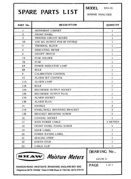
2 For information about: See page: ACCURACY 9 ALARM FUNCTION AUTOMATIC CALIBRATION 2 6 BENCH/SHELF USE CABINET DETAILS 4 2 CIRCUIT DIAGRAMS 16&17 COMMISSIONING CONSTANT TEMPERATURE UNIT 6 10 DEFINITIONS DEWPOINT TEMPERATURE DRAWINGS ELECTRICAL CONNECTIONS ELECTRICAL FUNCTION CHECK 13 GASES TO AVOID GENERAL DESCRIPTION 5 2 GUARANTEE HAZARDOUS AREA INSTALLATION 5 10 HYGROMETRIC EQUIVALENTS 25 IDENTIFICATION (SENSOR) INSTALLATION (INSTRUMENT) 9 3 INSTALLATION (SENSOR) OUTPUT SIGNAL 4 2 PANEL MOUNTING PARTS LIST 4 15&19 PARTS PER MILLION 10 POWER SUPPLY PRESSURE 2 4 RANGE CHANGE (TWIN RANGE) RANGES 2 9 RELATIVE HUMIDITY RESPONSE TIME 10 5 SENSOR CABLE 7 SENSOR CONNECTION SIGNAL CONVERTER 2 10 SPECIFICATION TEMPERATURE (INSTRUMENT) 26 3 TEMPERATURE (SENSOR) 9 THEORY TROUBLE SHOOTING 9 11 VACUUM VIBRATION 5 4 WALL MOUNTING WATER VAPOUR PRESSURE 4 10 WEATHERPROOF MODULES 8 Customer: Order Number: Shaw/Dealer Reference: Date: 1
3 GENERAL DESCRIPTION The Model SHA-SS is designed for continuous operation and gives analogue or digital indication in Dewpoint Temperature and/or parts per million, together with an analogue output signal, and one or two infinitely and separately adjustable alarm functions. No aluminium is used in its construction, making it particularly suitable for off-shore installations. CABINET Front panel stainless steel. Enclosure zinc-plated (Zintec) steel, stove enamelled. 254 x 152 x 159mm. Weight 3.5Kgs. Four feet fitted for bench or shelf use. Wall mounting brackets supplied as standard (fixing centres 26 x 241mm). Panel Mounting cut-out 238 x 162mm. CONNECTIONS All connections are on the right hand end of the instrument looking from the front. To special order they can be on the rear panel. POWER SUPPLY Approximately 2 metres of 3 core, colour coded, power cord is supplied. (COLOUR CODE: Live/Brown, Neutral/Blue, Earth (Ground)/Yellow-Green). A rating plate next to the fused power input socket identifies the required power supply, which can be 100/120V or 200/240V a.c. 50/60Hz (500mA. maximum) or 24V d.c. (regulated) 150mA maximum. Reference to the circuit diagram in this manual shows how the supply may be changed between 100/120V and 200/240V. The 24V d.c. models cannot be changed. Note that there is a spare fuse in the power input socket. OUTPUT SIGNAL The output signal is available on the 4-pin socket. The two right-hand terminals are negative (and common to earth) the two left-hand terminals are positive. The signal is pre-set to 100mV d.c. at maximum scale reading and is suitable for high impedance loads of 50K ohms or greater. By adjustment of VP3 on the printed circuit board inside the instrument, it may be set to any lower value. This output becomes the input signal of the Shaw Signal Converter, which is available as an optional extra. To special order, the Signal Converter can be mounted inside the Model SHA-SS. SENSOR The sensor is connected to the instrument by means of special coaxial cable. The sensor connection socket is a UK TV-type and is located on meter end-panel with the other electrical connections. ALARM FUNCTION Connection to the contacts of the alarm relay is through the 3-pin socket. Terminal 3 is common, and terminals 1 and 2 are normally open (N/O) and normally closed (N/C) respectively. (If the alarm is wired for fail-safe operation the N/O and N/C connections are reversed). In instruments fitted with the optional second alarm, two separate 3-pin sockets are fitted. IMPORTANT:THE L, N & E markings in the plug DO NOT APPLY. Contact rating is 2A at 240V a.c. Adjustment of the alarm trip position is by means of the front panel mounted control marked Set Alarm. Remove the protective cover by unscrewing it, and the potentiometer spindle is revealed. The slot in the spindle should be used as a pointer to indicate the trip position, using the markings on the instrument front panel, which indicate the scale percentage. E.g. If the spindle slot is in line with 100% then the alarm will trip at full scale. If it is in line with 5, then the alarm will trip at 50% of scale, and so on. RANGE CHANGE (Twin Range models only) To select the more sensitive range, press the red button. The button will be illuminated for as long as this range is selected. Pressing the red button again will reset the instrument to its normal range. IMPORTANT: Note that the output signal and alarm trip position both function as a percentage of scale deflection. This means that a reading of 50% of scale will result in an output signal of 50mV regardless of which range is selected. 2
4 INSTALLATION. The installation drawing at the end of this manual shows all the components which may be used in a dry gas measurement application, although not all items are needed in every installation. (See page seven for the SWS & SHA-SS models) A sample of the gas to be monitored is taken from the upper surface of the main gas line (or from a vertical section of the pipe) in order that dirt or condensate should not be introduced into the sample. 1/8 o.d. stainless steel pipe is the preferred sample connection although all components we supply are available with fittings for 1/4 o.d. or 6mm o.d. pipe for those cases where a larger diameter pipe is preferred. The sample pipe should first be connected to a filter unit if there is any risk of dirt or liquid entrainment in the sample. The filter unit should be positioned as close to the main line as possible in order to protect the sample system as well as the sensor from contamination. From the filter unit the sample passes through a pressure regulator (a simple needle valve is frequently sufficient for this purpose), when it is necessary for the pressure to be reduced. From the pressure control the sample passes immediately into the sensor mounted in its sensor holder. The outlet of the sensor holder is connected to the desiccant chamber (if used) and then to the flow indicator (again, if used). The sample is normally vented to atmosphere. It is important to note that nothing is installed before the sensor unless it is absolutely necessary this is to avoid any risk of changing the moisture content of the sample before it has been measured! In particular avoid pressure regulators with rubber diaphragms and flow meters. Where possible, the sample piping should run upwards from the sample point to the sensor so that any contamination introduced into the system will tend to fall back into the main line, and not be forced further into the sample system. If a downward sloping sample connection is necessary, form a U-bend before the sensor, with a drain tap, which should be checked regularly for condensate. If any other analysis of the sample is needed (for oxygen content, for example) install the other analyser after the Shaw sensor: our sensor does not change the composition of the sample in any way. For a closed loop sample system, the exhaust from the sensor should be connected to a lower pressure point within the main system, in order that a flow should be induced within the sample system. By reversing the order of items 4 & 6 (Installation Schematic) - the pressure control and the sensor in its holder - the sensor can be made to operate at line pressure. When the system is installed and a stable reading has been obtain, INCREASE THE SAMPLE FLOW RATE temporarily, and if a drier reading results, it indicates that the original flow rate was too low, or that there is a leak in the system allowing ambient moisture into the sample. INSTALLATION CONDITIONS INSTRUMENT: All Shaw instruments will operate within a temperature range of 30/+40 deg C. Select an installation position where this temperature range will not be exceeded, particularly avoiding positions where direct sunlight may fall upon the instrument, especially when it is installed in a weatherproof enclosure (which naturally has no ventilation). 3
5 WALL MOUNTING The two wall mounting brackets should be fastened to the instrument using the two screws at the rear of each end panel. Provide a secure mounting for the four screws which will hold the brackets to the wall. PANEL MOUNTING The instrument will have been delivered with the mounting brackets in the panel mounting position. Having made a suitable cut-out in the panel (see page two for details), remove the brackets from the instrument, position the instrument in the panel from the front, refit the brackets and tighten the two clamp screws to secure it in place. BENCH OR SHELF USE Select a situation which is convenient for the user to view the Instrument, and at the same time avoid accidental damage. VIBRATION Shaw instruments are widely used in ships engine rooms and similar situations where vibration is present. However, to obtain maximum life and reliability we recommend that an installation position be selected where the minimum vibration will be present. Alternatively arrange for resilient mountings. INSTALLATION CONDITIONS: SENSOR PRESSURE The Shaw sensor is a water vapour pressure detector. This means that it is sensitive to its operating pressure. However, dewpoint temperature is directly proportional to pressure (as the pressure of a gas is increased the dewpoint temperature increases to a wetter level) and so the dewpoint temperature readings given by the instrument remain correct regardless of the pressure at which the sensor is used. IMPORTANT: It is most important to remember that the parts per million (PPM) scale on the instrument is only correct when the sensor is operating at 1 bar(a) pressure. If the sensor is operating at any other pressure the readings in PPM must be corrected by the use of a pressure nomograph or calculator (available from us). Although Shaw sensors are in regular use at up to 200bar it is generally preferred that the sensor be operated at 1 bar(a). The advantages of this are: 1. The readings will not be affected by changes in the gas pressure in the main pipe. 2. With a typical line pressure of about 7 bar the sensor will never be exposed to free water, even under major fault conditions, as the sample of gas at 1 bar will have a dewpoint temperature of only about 0 deg C. This means that the instrument readings continue to give useful information, and recovery of the sensor after the fault condition has been cured will be very much quicker. The sensor is a water vapour pressure detector, and free water is an enormous overload. Contamination of the sensor with free water will, at best make the calibration suspect and so should be avoided. This is true for ALL electronic sensors, regardless of the claims made by some manufacturers. If readings at line pressure are necessary, we can supply a special scale, which will show the line pressure dewpoint temperature with the sensor operating at 1 bar. The line pressure must be reasonably constant for this to be satisfactory. Alternatively, if the sensor is operated at line pressure, the standard scale will indicate the correct dewpoint temperature directly without correction. 4
6 VACUUM As stated above the Shaw Sensor is a water vapour pressure detector. It therefore follows that it will operate under vacuum and continue to indicate correctly the water vapour pressure, which remains. As with high-pressure operation it is important to remember that the PPM scale is only correct with the sensor operating at 1 bar. The dewpoint temperature readings remain correct regardless of the system pressure or vacuum. Also remember, when changing the pressure in systems containing small amounts of water vapour, that a new equilibrium must be established at a new pressure before the final reading will be obtained. Out-gassing or absorption of water vapour molecules from the pores of the materials out of which the system is constructed can cause a considerable time delay, sometimes leading to unexpected results! RESPONSE TIME The response time from dry to wet of all Shaw sensors is a maximum of 30 seconds for 90% of a step change, depending upon the moisture level and the temperature. The response from wet to dry depends very much upon the operating conditions, and will be affected by the sensor and gas temperature and pressure, and the sample flow rate. In general, the sensor is able to establish a new equilibrium water vapour pressure after a change in conditions at least as quickly as the system in which it is installed. In order to obtain the best possible system response time it is important to design the sample system carefully. Use the smallest sample pipe possible (we usually suggest 1/8 o.d.) and use the shortest possible length. It is always preferable to use a longer coaxial cable to the sensor, rather than a long sample pipe from the sample point. The sample flow rate should be adequate for the size of sample system: for an average installation having perhaps 2 metres of 1/8 o.d. pipe before the sensor, a flow rate of about 1 L/min. is quite sufficient. If a longer sample pipe is used, then the sample flow should be increased. If necessary, install a by-pass type of system with a high flow rate purging the system and a small proportion of that flow passing over the sensor. When the system is installed and a stable reading has been obtain, INCREASE THE SAMPLE FLOW RATE temporarily, and if a drier reading results, it indicates that the original flow rate was too low, or that there is a leak in the system allowing ambient moisture into the sample. IMPORTANT Shaw sensors are suitable for many different industrial and research applications. Most gases can be checked for their moisture content, and there is no need for the calibration to be altered when changing between different gases, even such different gases as Carbon Dioxide and Hydrogen: the sensor operates only with reference to the water vapour content. However there are some gases which must be avoided as they are not compatible with the materials of construction of the sensor. Ammonia and Chlorine must be avoided at all times, even in small quantities. HCL also attacks the sensors very quickly. Gases such as Sulphur Dioxide (SO2) can be monitored, as long as the moisture content is low, generally less than l00 PPM. If in doubt, please check with us first. GUARANTEE All Shaw products are guaranteed for two years from date of purchase, only excluding accidental damage or misuse. (This may be limited to one year if purchasing from the stock of one of our overseas distributors) 5
7 COMMISSIONING AND CALIBRATION CHECKING One of the most valuable advantages of the Shaw measurement system is the Automatic Calibration feature. Not surprisingly, some other manufacturers suggest that there is some doubt about its effectiveness: this is because no other instrument can be checked so easily and quickly. The system relies on the fact that each sensor is designed to give no further increase in reading when it reaches its maximum moisture level. This means that, for instance, the RED SPOT sensor will read -20 deg C dewpoint when it is exposed to gas at -20 deg C dewpoint, and will continue to read -20 C dewpoint when it is exposed to wetter gas. The system can therefore be calibrated very simply by exposing the sensor to anything wetter than -20 deg. C dewpoint, and adjusting the reading to that point on the dial. This enables the instrument to retain the maximum possible accuracy throughout it range. A new instrument is calibrated as follows: PURPLE, SILVER, GREY, RED & YELLOW SENSORS 1. Select the channel to be calibrated on the front panel selector switch and if the instrument is a dual range model, select the standard (less sensitive) range. 2. Turn the control marked Automatic Calibration fully anti-clockwise (until it clicks), and then turn it about 3 turns clockwise). Connect one end of the sensor cable to the instrument, and the other end to the coaxial socket on the end of the sensor, this is exposed when the lid is removed from the can in which the sensor is packed. A reading of less than full scale, but above the minimum (left-hand) scale marking should be obtained. This confirms that the instrument, cable and sensor are all working correctly. (If in doubt, refer to the trouble shooting section of this manual). 3. Disconnect the sensor cable from the sensor and remove the sensor from its dry packing. Reconnect the cable to the sensor and, after the sensor has been exposed to the room air for about 1 minute, adjust the Automatic Calibration control on the Moisture Analyser so that the reading is at the Automatic Calibration line. (For Digital versions there is no Auto-cal line and therefore the meter must be set to the WET limit of the sensor). 4. Disconnect the sensor cable from the sensor, install the sensor in its working position, and reconnect the sensor cable to the sensor socket. The complete system is now calibrated. 5. Repeat this procedure for each channel in turn. WE RECOMMEND THAT THE AUTOMATIC CALIBRATION BE CHECKED ONCE OR TWICE A YEAR: - 1. Remove the Sensor from its normal. position so it is exposed to room air. 2. Leave the Sensor for about one minute (not critical, but not more than a few minutes) 3. IF NECESSARY, adjust the Automatic Calibration Control so that the meter reading is on the AUTOMATIC CALIBRATION LINE. (For Digital versions there is no Autocal line and therefore the meter must be set to the WET limit of the sensor). 4. Put the Sensor back in its normal position. 6
8 COMMISSIONING AND CALIBRATION CHECKING (continued) GOLD, GREEN & BLUE SPOT SENSORS Calibration should be carried out by comparison with the results of a good quality sling hygrometer, taking the average of several results, or by comparison with some other independent means of checking the room air dewpoint temperature. Allow the sensor to come into equilibrium with the room air and then adjust the Automatic Calibration control until the reading is the same as the room air dewpoint temperature. Alternatively, the instrument may be calibrated approximately by the Automatic Calibration method described above. With Green Spot and Gold Spot sensors, however, room air will not normally be above the cut-off point of +20 deg dewpoint. However, this is easily overcome by removing the sensor from its dry packing, after carrying out the initial test to confirm that the instrument, cable and sensor are all functioning correctly, and holding the measuring area firmly in the palm of the hand for a maximum of 30 seconds. The Moisture Analyser reading should then be adjusted to +20 deg C dewpoint by means of the Automatic Calibration control, while the sensor is still held in the hand. The sensor may now be installed in its normal working position. (Moisture coming from the palm of the hand will ensure that the sensor is exposed to a moisture level greater than its design maximum of +20 deg C dewpoint). NOTES If any sensor is to be used at a temperature, which is more than a few degrees different to the room temperature, it is always best to carry out the calibration with the sensor at its normal working temperature. All calibrations are in dewpoint temperature. Conversions to parts per million (volume) are over water above 0 deg C and over ice below 0 deg. C dewpoint. SENSOR CABLE The sensor cable which is used to connect the sensor to the Instrument is of the coaxial type. It is 75 ohms impedance and has a capacitance of 50pF. or less per metre. Using this special cable, which is available from us in 100, 250 and 500 metre lengths, it is possible to position the sensor up to 1000 metres away from the instrument. Instruments are despatched with a standard length of 2 metres of cable, unless a longer length is requested. When using a longer length of cable for the sensor connection, the instrument will show a small reading with the sensor disconnected. This is quite normal, and is due to the capacitance of the cable itself. Locate the Meter Zero control on the circuit board of the instrument and adjust the instrument reading (and the output signal) to zero with the cable connected to the instrument, but without the sensor. 7
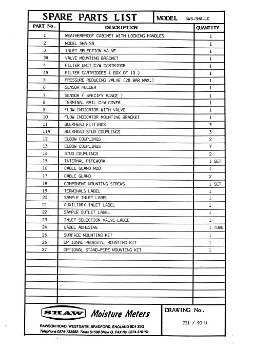
9 SHAW WEATHERPROOF MODULES: INSTRUCTIONS Shaw Weatherproof Modules are manufactured from high impact polycarbonate and GRP and are rated IP65. SWS-SS models are the sample system only and would normally be used in conjunction with the SHA-SS. The Instructions given here are in addition to the general instructions given elsewhere in the manual which relate mainly to the meter and sensors operation. 1. All units should be mounted securely on a vertical surface. 2. Access to the inside of the enclosure is obtained by disengaging the locking devices, which are located in each corner of the lid. Using a broad bladed screwdriver, press the locking device in and turn anti-clockwise through 90 deg. To replace the cover, reverse this procedure. 3. Ensure that all gas/air connections are secure, and that there are no leaks. 4. Observe correct polarity and voltage of all electrical connections and provide a secure earth (ground) connection. 5. Install the sensor, carrying out the automatic calibration procedure as described earlier in this manual. 6. BEFORE connecting the gas/air sample, open the flow indicator valve fully, and close the regulator completely (both fully anti-clockwise). 7. Check that the sample pressure does not exceed the maximum for which the unit is designed. (This will be 28 or 200 or 400bar, depending on your order specification. 8. Turn on the sample at source and then slowly open the regulator (clockwise) until the flow indicator reading is just over its maximum calibration mark. 9. Close the flow indicator valve (clockwise) until the flow indicator shows the required flow rate (usually about 1 to 2 L/min. 10. Observe the small reading on the pressure gauge (if fitted). This is not critical, and will not influence the meter readings. A zero reading will warn of loss of sample. 11. Re-fit lid and securely fasten. Other operational information will be found in the other pages in this manual. NOTES: The sensor for the unit will be supplied in its own separate packing. We suggest that it remains in this packing until the complete unit has been installed, and the sample piping purged. The sample piping to the unit should be kept a short as possible. The sample tapping point should be on an upper surface of the main line (or on a vertical section), and piping should run upwards to the Shaw unit wherever possible. These precautions will help to avoid possible contamination of the unit with condensate under fault conditions. If downward sloping pipe is unavoidable, from a U bend with drain tap immediately before the Shaw unit, and check regularly for condensate. Examine, and replace the filter cartridge at intervals determined by the amount of contamination and the sample flow rate. 8
10 THE SHAW SENSOR: DESCRIPTION, THEORY AND OPERATING CONDITIONS The Shaw High Capacitance Sensor has been undergoing continuous development since it was invented by Mr.. J. L. Shaw in the late 1940 s. CONSTRUCTION of the sensor starts with an ultra-high purity aluminium wire, which is coated with a hygroscopic layer and finally covered by a film of porous gold. The gold film and the aluminium core form the plates of a capacitor. The capacitance value, and the change in capacitance value over the measuring range of each sensor (which is at least 100 times greater than in any other sensor of this type) is measured at supply frequency (50 or 60Hz) which enables long cable lengths (up to 1000M) of cable to be used between each sensor and the analyser without any risk of interference or pick-up from external cables or other sources. Some of the water vapour molecules in the atmosphere surrounding the sensor will enter the dielectric layer where, due to the extremely small size of the pores, their Brownian motion will be restricted and the energy will be removed from the molecules so that they will condense into liquid water. Due to the very high dielectric constant of water (about 80) compared with the other vapours which may be present, this produces a marked change in the dielectric value of the sensor which is then measured by the analyser. A dynamic equilibrium will exist between the water vapour outside the sensor and the condensed water within the pores. This equilibrium is maintained, and the response time of the sensor can generally be considered to be at least as quick as the system into which it is installed. Molecules larger than water vapour (which is one of the smallest gas molecules) cannot enter the pores, making the sensor resistant to many contaminants and specific to water vapour pressure regardless of the carrier gas. (Molecules of gases such as Hydrogen will enter the sensor pores, but their dielectric strength is small enough that no measurable change occurs in the sensor) TEMPERATURE Shaw sensors are designed to work at normal room temperature. Our long experience of exporting to countries throughout the world has shown that ambient temperature variations can safely be ignored for all practical purposes, so long as the temperature range for each sensor given below is not exceeded. In particular, avoid placing any sensor in direct sunlight or near a source of radiant or convected heat. For special applications where high or low temperature operation seems unavoidable, please refer to your local Shaw dealer or us. OPERATING TEMPERATURE: All sensors operate accurately in the temperature range 35 to +40 deg. C, excepting Gold, Green and Blue Spot sensors whose operating temperature range is +5 to +35 deg. C. When calibrated within +/- 5 deg. C of operating temperature. SENSOR TO USE. Range: Purple: {P} -100 / 0 deg.c DP, PPM. Silver: {S} -100 / -20 deg.c DP, PPM, and 0-10 on TR version. Red: {R} -80 / -20 deg.c DP, PPM, 0-10 on TR version, and 0-1 on TRS. Grey : {GY} -80 / 0 deg.c DP, PPM, and 0-10 on TR version. Yellow: {Y} -60 / 0 deg.c DP, PPM. Gold : {GO} -50 / +20 deg.c DP, 40-23,000 PPM, (manual-cal). Green : {GR} -30/+20 deg. C DP, ,000 PPM, (manual-cal). Blue: {BL} -80 / +20 deg.c DP, 0-23,000 PPM, (manual-cal). ACCURACY Red Spot Sensors; +/- 3 deg C Dewpoint or +/- l PPM (whichever is greater). When using 0 to 1 PPM range; +/- 5% of scale. All other sensors; +/- 4 deg C Dewpoint. IDENTIFICATION. Shaw Sensors are identified by a coloured spot on the handle. 9
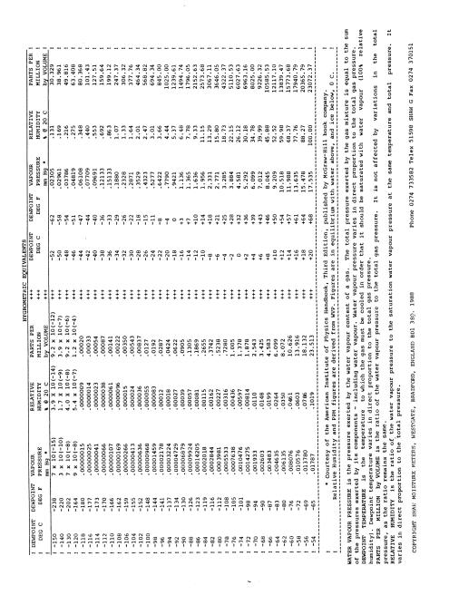
11 SIGNAL CONVERTER The standard output signal from the SHA-SS is 0-100mV d.c. This may be used as the input to the Shaw Signal Converter in order to obtain a transmission signal of 0-20 or 4-20mA d.c., suitable for 500 ohms maximum load, or 0-10, 1-10, 0-5 or 1-5V d.c. suitable for high impedance loads. The Shaw Signal Converter has its own separate power supply and may therefore be mounted with the analyser, or remote from the instrument if this is more convenient. Please note that the standard analyser has its negative terminals connected to earth. A fully isolated programmable converter is available, on request, at extra cost. HAZARDOUS AREA INSTALLATION The Shaw Sensor has been approved for use as part of an intrinsically safe circuit. This means that it may be installed in an area where there is risk of fire or explosion. The instrument must be located in a safe area, and the length of coaxial cable between the instrument and sensor must be no more than 300 metres. In addition, a Zener Barrier Unit must be installed in the safe area and connected between the instrument and its sensor. The Zener Barrier Unit is a device, which limits the amount of energy, which can reach the sensor, even in a major fault condition, to less than that required to cause a spark which could ignite the explosive gas. All instruments ordered for hazardous area operation are supplied with a copy of the relevant certificate. This can be BASEEFA (U.K.), CENELEC (European) or FACTORY MUTUAL (U.S.A.). CONSTANT TEMPERATURE UNIT. This is used in place of the Sensor Holder when there is a risk of condensation on the sensor due to wide ambient temperature variations or, in non-standard applications, when the gas dewpoint temperature may be higher than the ambient temperature. It should be used in exactly the same way as the Sensor Holder, and the thermostat should be set to the temperature indicated on the information supplied with the sensor. BASIC DEFINITIONS WATER VAPOUR PRESSURE is the pressure exerted by the water vapour contained in any mixture of gases. The total pressure exerted by the gas mixture is the sum of the pressures exerted by its components - including the water vapour. Water Vapour Pressure varies in direct proportion to the total gas pressure. DEWPOINT TEMPERATURE is defined as the temperature to which the gas must be cooled in order that it should be saturated with water vapour (i.e.: 100% relative humidity.) For practical reasons it is referred to water above 0 deg C and ice below 0 deg C. PER MILLION BY VOLUME: PPM(v) or VPM is the ratio of the water vapour pressure to the total gas pressure. Where PPM is referred to in this manual it assumes PPM(v) unless otherwise stated. PARTS PER MILLION BY WEIGHT: PPM(w) is similar to VPM, except that the figure is modified according to the ratio of the molecular weight of water vapour to the molecular weight of the carrier gas mixture. RELATIVE HUMIDITY is the ratio of the actual water vapour pressure in the gas to the saturation water vapour pressure at the same temperature. 10
12 TROUBLE SHOOTING SYMPTOM: ERRATIC READINGS REMEDY CAUSE: Static on Indicator: Moisten indicator face with 50/50 mixture of detergent and water, or use proprietary anti-static cleaner. DO NOT POLISH INDICATOR FACE SYMPTOM: FULL SCALE READING CAUSE: Wet gas: Short circuit on sensor: Short circuit sensor: REMEDY Stop gas supply and switch meter off. Disconnect plug from sensor and if meter cable or connections still reads over FSD, cure the short circuit in the cable or connections or replace cable. Disconnect plug from sensor and note that the meter reading returns to zero. Fit new sensor, or apply approx. 20V d.c. to the sensor MOMENTARILY with the sensor in a known dry condition, polarity is not important. SYMPTOM: ZERO READING CAUSE: Open circuit on cable: CAUSE: Open circuit on sensor: CAUSE:Instrument un-serviceable: CAUSE: Automatic Calibration: wrongly set REMEDY Disconnect plug from sensor and connect centre pin of plug to the outer connection. No reading will be obtained. Repair cable. Test as for open circuit on cable, but note that reading over FSD obtained. Check sensor connection or replace sensor. Connect centre pin of sensor cable socket on instrument to its outer connection and note that no reading is obtained even with sensitivity control setting increased. Return instrument for service. Readjust to correct setting [i.e. carry out the Automatic Calibration procedure]. 11
13 TROUBLE SHOOTING SYMPTOM: WET READING CAUSE: Leak in system or use of unsuitable pipe. REMEDY Cure the leak, or replace unsuitable pipe with copper or stainless steel. Flexible connections should be made with PTFE pipe. NEVER use rubber or plastic pipe. SYMPTOM: SLOW RESPONSE CAUSES:Water vapour in system. : Flow rate too low: Sample pipe too large: Unsuitable sample pipe: It is usually more satisfactory to bleed a sample of gas at atmospheric pressure through the sensor in its sensor holder and to use 1/8 [3mm] o.d. sample pipe. See above re sample pipe material. SYMPTOM: DRY READING CAUSE: Automatic Calibration: wrongly set, or faulty Sensor REMEDY Check Automatic Calibration, or return sensor for full calibration check by us. SYMPTOM: CONSTANT READING REMEDY CAUSE:Condensation in sample system. Condensation will occur if the temperature of the sample system, at any point is below [colder] than the dewpoint temperature of the sample gas. Once having formed, the sample reaching the sensor will have a dewpoint equal to the temperature of the condensation, regardless of the dewpoint of the sample at the sample point. 12
14 ELECTRICAL FUNCTION CHECK SHA-SS INSTRUCTION MANUAL If there is any doubt about the functioning of the Analyser, the following tests may be carried out. 1. Switch instrument off. 2. Check that meter reading is accurately at the zero [left-hand] end of the scale. If not, adjust the reading by means of the plastic screw on the meter face. 3. Disconnect the sensor[s]. 4. Check the required power supply [24V d.c., 100 or 230V a.c.] and then switch instrument on. 5. Apply a short circuit to the sensor cable socket on the instrument, the voltage is extremely low, so there is no hazard. [If checking a multichannel instrument, select channel 1 and apply the short circuit to socket 1. Repeat all steps on this test on all channels. 6. Adjust the Automatic Calibration to give a reading of full scale. 7. Remove the short circuit and the reading should return to the left-hand end of the scale. This establishes that there is no major fault in the instrument. If the tests so far do not produce the expected results, the instrument should be returned to our Bradford works, or your local dealer. 8. Remove the short circuit and replace it with a load of 8.6K ohms. Readjust the reading to full scale, using the Automatic Calibration. 9. Increase the load to 18.6K ohms. The reading should decrease to 61% of scale +/-1% 10. Increase the load to 62K ohms. The reading should decrease to 21% of scale with the same tolerance as above. 11. Using any type of continuity tester, check the normally open and normally closed contacts of the alarm relay, using the Set alarm control to operate the relay. 12. Using a suitable high impedance multimeter, check the value of the output signal against the instrument specification. 13. After testing the instrument electrically, reset the Automatic Calibration of the sensor. This completes the Electrical Function Test NB: As the body of the sensor is earthed, it is important that the earth potential at the sensor is the same as that in the power supply earth to avoid stray pick-up. This is very rarely a problem, but if in doubt, check for a voltage between the sensor body and the sensor holder before installing the sensor. 13
15 14
16 15
17 16
18 17
19 18
20 19
21 20
22 21
23 22
24 23
25 24
26 25
27 SHA-SS Specification Accuracy (meter): Accuracy (sensor): Type: 1% across meter range. See sensor specification sheet. Portable hygrometer in Stove enamelled stainless steel case for wall or panel mounting suitable for off shore use. Dimensions / Weight: Overall dimensions: Panel cut-out: 254 x 187 mm, Depth 152. Weight: 2.5 Kg approx. Display: Sensor Connection: Power Supply: 12cm Taut Band indicating meter showing Dewpoint and ppm, with amplified range of 0-10ppm on TR versions. Low loss co-ax cable (75ohms max capacitance of 50pF per metre). Sensor location upto 1000m from meter except after Zener Barrier then 300m. 110 or 220 V a.c. single phase 50 or 60 Hz and 24V d.c. Sampling: Pressure upto 200 Bar preferably atmospheric with flow rate of 1-5 litres/minute in Shaw Sensor Holder. Outputs: Calibration: Accessories / Options: Alarms:1 Relay rated at 240V 3A Analogue: 0-100mV(standard) or 4-20mA Autocal on all but Blue, Gold and Green ranges Zener Barrier Unit ZBU for intrinsically safe operation in hazardous areas to Eex.ia IIC T6 SU4 Lo, Med or Hi Sample system for sample conditioning pressurised gases to atmospheric conditions and controlled flow. SWS Lo, Med or Hi Sample system, as SU4 but in IP rated cabinet. Sensor Type (r): Purple: (P) Silver : (S) Red : (R) Grey : (GY) Yellow : (Y) Blue: (BL) Gold : (GO) Green : (GN) To Order: State Voltage Sensor Range: -100 / 0 deg.c DP, ppm, (auto-cal) -100 / -20 deg.c DP, ppm, 0-10 on TR version, (auto-cal) -80 / -20 deg.c DP, ppm, 0-10 on TR version, (auto-cal) -80 / 0 deg.c DP, ppm, (auto-cal) -60 / 0 deg.c DP, ppm (auto-cal) -80 / +20 deg.c DP, 0-23,000 ppm (manual-cal) -50 / +20 deg.c DP, 40-23,000 ppm (manual-cal) -30 / + 20 deg.c DP, ,000 ppm (manual-cal) SHASS - (r): 0-100mV + 1 alarm, suffix TR if required for S and R SHASS20 - (r): 4-20mA + 1 alarm, suffix TR if required for S and R 26
CONTENTS UNPACKING YOUR SUPER-DEW...1
 CONTENTS UNPACKING YOUR SUPER-DEW...1 SETTING UP AND INITIAL CALIBRATION...2 DRY LIMIT SETTING...2 WET LIMIT SETTING (AUTO-CAL)...2 CALIBRATION ROUTINE...3 ALARM SETTINGS...4 ALARM TRIPS AND HYSTERESIS...4
Analizador SADP Higrómetro Instructivo de Operación
 Analizador SADP Higrómetro Instructivo de Operación Shaw Moisture Meters México MazaTech S.A. de C.V. Ignacio Zaragoza #225 Zona Centro; C.P. 37000; León, Gto. Tel: (477) 763-1000 / 763-1001 / 763-1009.
Model SADP Automatic Dewpoint Meter. Instruction Manual
 Model SADP Automatic Dewpoint Meter Instruction Manual Contents 1 2 3 4 5 6 7 8 9 10 11 12 13 14 Unpacking your Shaw Moisture Meters Model SADP... 4 1.1 General Description... 4 1.2 Ranges... 5 Hazardous
Model PDT Dewpoint Transmitter
 Model PDT Dewpoint Transmitter Instruction Manual Alpha Moisture Systems Alpha House 96 City Road Bradford BD8 8ES England Tel: +44 1274 733100 Fax: +44 1274 733200 email: mail@amsytems.co.uk web: www.amsystems.co.uk
AMT-Ex Dewpoint Transmitter
 AMT-Ex Dewpoint Transmitter Instruction Manual Alpha Moisture Systems Alpha House 96 City Road Bradford BD8 8ES England Tel: +44 1274 733100 Fax: +44 1274 733200 email: mail@amsytems.co.uk web: www.amsystems.co.uk
Model SDT-Ex Dewpoint Transmitter. Instruction Manual
 Model SDT-Ex Dewpoint Transmitter Instruction Manual Issue 1.0 11/2010 Declaration of Conformity Index 1.0 2.0 3.0 4.0 5.0 6.0 7.0 8.0 9.0 10.0 11.0 12.0 13.0 14.0 Unpacking your Shaw Moisture Meters Model
Model SDT Dewpoint Transmitter
 Model SDT Dewpoint Transmitter Instruction Manual Issue 1.1 02/2008 EC Declaration of Conformity We Of Declare That: Model Name: Description: Shaw Moisture Meters Len Shaw Building, Bolton Lane, Bradford,
Columbus Instruments
 0215-003M Portable O 2 /CO 2 /CH 4 Meter User s Manual Columbus Instruments 950 NORTH HAGUE AVENUE TEL:(614) 276-0861 COLUMBUS, OHIO 43204, USA FAX:(614) 276-0529 1 www.colinst.com TOLL FREE 1-800-669-5011
DF-550E PROCESS ANALYSERS APPLICATIONS FEATURES
 PROCESS ANALYSERS DF-550E The DF-550E Nano Trace oxygen analyser is a Coulometric sensor based analyser designed to measure oxygen as a contaminant at ultra trace levels in ultra high purity electronic
Instruction Manual. Model DSP-Ex Portable Dewpoint Meter. Alpha Moisture Systems Alpha House 96 City Road Bradford BD8 8ES England
 Model DSP-Ex Portable Dewpoint Meter Instruction Manual Alpha Moisture Systems Alpha House 96 City Road Bradford BD8 8ES England Tel: +44 1274 733100 Fax: +44 1274 733200 Email: info@amsytems.co.uk Web:
Installation, operating and maintenance Instructions for Seemag bypass level indicator
 Issue: S Date: 05-09-14 Type G35 General information The Seetru bypass magnetic level indicator, abbreviate SEEMAG, serves to show the filling level of fluids in tanks, basins, tubes etc. The Seemag operates
Series 6517 Katharometers. The ideal equipment for Process Monitoring and Control. Robust no moving parts. Designed for continuous industrial use
 Data sheet Katharometers The ideal equipment for Process Monitoring and Control Designed for continuous industrial use Long working life Suitable for flammable gases CENELEC certified (ATEX) to EExia IIC
Model 130M Pneumatic Controller
 Instruction MI 017-450 May 1978 Model 130M Pneumatic Controller Installation and Operation Manual Control Unit Controller Model 130M Controller is a pneumatic, shelf-mounted instrument with a separate
Transmitter CS 21 Operation Manual
 Transmitter CS 21 Operation Manual Content Page For your Safety 3 General Description 3 Detection Principle 4 Operational Notes 4 Design 4 Mounting Position of CS21 5 Mounting 6 Installation of Electrical
Ventam 85 Installation & Commissioning Instructions
 Ventam Systems Ltd Unit D4 Seedbed Business Centre Vanguard Way Shoeburyness Essex SS3 9QY Phone 01702 382 307 Fax 01702 382 340 Ventam 85 Installation & Commissioning Instructions 1 General The Ventam
Operating Instructions
 Operating Instructions Sensors Type 705 H 2 S Sensor and Transmitter for Electrochemical Cells Ul Certified HELPING TO MAKE A SAFER WORLD Ensure that you read and understand these operating instructions
ACV-10 Automatic Control Valve
 ACV-10 Automatic Control Valve Installation, Operation & Maintenance General: The Archer Instruments ACV-10 is a precision automatic feed rate control valve for use in vacuum systems feeding Chlorine,
Instant moisture checks in Dry Air or Gas
 SADPG SDG Instant moisture checks in Dry Air or Gas Please bookmark bookmark this this site:site:please SSDIRG www.shawmeters.com for the the latest latest updates updates and and developments. developments.
Best Practice Guide, Servomex 2700
 For full installations details refer to the. Best Practice Guide, Servomex 2700 Mounting: General Guidelines: Servomex 2700 Control Units and air supplies (utilities units) should, ideally, be mounted
OPERATOR S MANUAL Ar-Gone Weld Gas Analyzer
 July 2011 OPERATOR S MANUAL Ar-Gone Weld Gas Analyzer WARNING! Before operating this product, read and understand this Operator s Manual. Become familiar with the potential hazards of this unit. Contact
Gas density monitor With integrated transmitter Model GDM-100-TI
 SF 6 gas solutions Gas density monitor With integrated transmitter Model GDM-100-TI grid Products WIKA data sheet SP 60.05 for further approvals see page 5 Applications Gas density monitoring of closed
Instruction Manual Contact Pressure Vacuum Gauge
 MS10 Instruction Manual Contact Pressure Vacuum Gauge Table of Contents 1. Safety Instructions 2. Intended Applications 3. Product Description and Functions 4. Installation 5. Commissioning 6. Maintenance
Technical Data Sheet MF010-O-LC
 Technical Data Sheet MF010-O-LC - 1 - 1. Properties The oxygen measuring system MF010-O-LC determines the oxygen content in gas mixtures up to a temperature of 250 C. It is particularly suitable for the
EASIDEW TRANSMITTER with Current Source Output
 EASIDEW TRANSMITTER with Current Source Output INSTALLATION, OPERATION AND MAINTENANCE MANUAL Issue March 2002 2 TABLE OF CONTENTS SECTION PAGE 1. INTRODUCTION 3 1.1 General 3 1.2 Ceramic Sensing Element
DF-310E PROCESS ANALYSERS APPLICATIONS FEATURES
 PROCESS ANALYSERS DF-310E The DF-310E is a Coulometric sensor based oxygen analyzer designed to measure trace and percent level oxygen in pure and multi-gas backgrounds for process and quality control
OXY Integral. INTERCON ENTERPRISES INC Tel: Fax: Internet:
 OXY Integral INTERCON ENTERPRISES INC Tel: 800 665 6655 Fax: 604 946 5340 E-Mail: sales@intercononline.com Internet: www.intercononline.com Manual Integral 2006 1 INDEX 2-3 PREFACE 4 INTRODUCTION 5 Principle
AK100 Series ATEX Compliant Gas Analyzer System for Hydrogen-cooled Alternators
 Data sheet DS/AK EN Rev. J AK Series ATEX Compliant Gas Analyzer System for Hydrogen-cooled Alternators Superior technology and quality from the world leader in hydrogen measurement ATEX compliant intrinsically
VERTICAL AIR COMPRESSORS
 VERTICAL AIR COMPRESSORS MODEL NO: VE11C150, VE15C150, VE18C150 PART NO: 2226005, 2226000, 2226015 OPERATION & MAINTENANCE INSTRUCTIONS LS0615 INTRODUCTION Thank you for purchasing this CLARKE Vertical
ABB MEASUREMENT & ANALYTICS DATA SHEET. AK100 Series ATEX compliant gas analyzer system for hydrogen-cooled alternators
 ABB MEASUREMENT & ANALYTICS DATA SHEET AK100 Series ATEX compliant gas analyzer system for hydrogen-cooled alternators AK100 S E RIE S ATEX COMP LI AN T GAS ANALY ZE R SYSTE M DS/AK100-E N RE V. O Measurement
Transmitter CS 21 Operation Manual
 Transmitter CS 21 Operation Manual 1194 Oak Valley Drive, Suite 20, Ann Arbor, MI 48108 800-959-0573 734-769-1888 Content Page For your Safety 3 General Description 3 Detection Principle 4 Operation 4
VERTICAL AIR COMPRESSORS
 VERTICAL AIR COMPRESSORS MODEL NO: VE15C150, VE18C150, VE25C150 PART NO: 2226010, 2226020, 2226025 OPERATION & MAINTENANCE INSTRUCTIONS LS0715 INTRODUCTION Thank you for purchasing this CLARKE Vertical
AUTOMATIC GAS MANIFOLDS
 AUTOMATIC GAS MANIFOLDS Phoenix Pipeline Products Limited. Unit 8, McKenzie Industrial Park, Tel No.: 44 (0) 161 428 7200 Bird Hall Lane, Fax No.: 44 (0) 161 428 7010 Stockport, Email: info@p3-phoenix.com
High-performance submersible pressure transmitter For level measurement Model LH-10
 Electronic pressure measurement High-performance submersible pressure transmitter For level measurement Model LH-10 WIKA data sheet PE 81.09 Applications Level measurement in rivers and lakes Deep well
Installation, Operation and Maintenance Instructions for Electronically Controlled Pressurisation Units
 Installation, Operation and Maintenance Instructions for Electronically Controlled Pressurisation Units Models: EPS Single Pump EPT Twin Pump EPS-HP EPT-HP Single Pump High Pressure Twin Pump High Pressure
HBLT-A1 LIQUID LEVEL SENSOR
 Instruction manual HBLT-A1 LIQUID LEVEL SENSOR for measuring liquid level in refrigerant vessels Instruction manual HBLT - A1 - Liquid level Transmitter (HBLT-A1-008-UK) 1 / 16 Contents Safety instructions...
ECONORESS ELECTRONIC EPS & EPT - ENHANCED PRESSURISATION SET INSTALLATION OPERATION & MAINTENANCE DOCUMENTATION
 ECONORESS ELECTRONIC EPS & EPT - ENHANCED PRESSURISATION SET INSTALLATION OPERATION & MAINTENANCE DOCUMENTATION OCT2010 STOKVIS ENERGY SYSTEMS 96R WALTON ROAD EAST MOLESEY SURREY KT8 0DL TEL: 020 87833050
PURA. Pure Gas Dewpoint Transmitter. Users Guide
 PURA Pure Gas Dewpoint Transmitter Users Guide Issue January 2003 Page 2 Table of Contents SECTION PAGE 1 Product Overview 3 2 Preparation 3 3 Installation 3 3.1 PURA Premium & OEM Dewpoint Transmitter
![[Instruments for vacuum measurement, checking and adjustment] 3](/thumbs/94/121874202.jpg "[Instruments for vacuum measurement, checking and adjustment] 3")
TECHNICAL DATA MAINTENANCE AIR COMPRESSOR MODEL G-1
 Dry 131h 1. DESCRIPTION The Viking Model G-1 Maintenance Air Compressor is an electric motor-driven, aircooled, single-stage, oil-less compressor. The unit is equipped with a check valve and provides a
GasSense NDIR User Manual
 INDEX INDEX... 1 1. OVERVIEW... 2 2. TECHNICAL DATA... 3 3. SPECIFICATIONS... 4 4. PRODUCT DESCRIPTION... 5 4.1 Mechanical details... 5 4.2 Piping... 7 4.3 Connections... 7 5. INSTALLATION... 10 6. CALIBRATION
Electropneumatic Transducer (I/P) Installation, Operation and
 Installation, Operation and") Nitra NCP1 Series Electropneumatic Transducer (I/P) Installation, Operation and Maintenance Instructions Ordering Information Contents Part Number I/P Transducers Output Range Input psig bar Section Description
Nitra NCP1 Series Electropneumatic Transducer (I/P) Installation, Operation and Maintenance Instructions Ordering Information Contents Part Number I/P Transducers Output Range Input psig bar Section Description
24L OIL FREE AIR COMPRESSOR MODEL NO: TIGER 7/250 PART NO: OPERATION & MAINTENANCE INSTRUCTIONS LS10/13
 24L OIL FREE AIR COMPRESSOR MODEL NO: TIGER 7/250 PART NO: 2244030 OPERATION & MAINTENANCE INSTRUCTIONS LS10/13 INTRODUCTION Thank you for purchasing this product. Before attempting to use this product,
FLAMMABLE GAS SENSOR/TRANSMITTER
 FLAMMABLE GAS SENSOR/TRANSMITTER Plant safety protection for flammable gases. F E A T U R E S Fixed gas monitoring for point source hazards and perimeter protection in arduous duty and exposed locations.
Air Sensor. SAC Ex. Manual ATEX. AQ Elteknik AB
 Air Sensor SAC Ex Manual AQ Elteknik AB ATEX Air Sensor SAC Ex ATEX Certified model Manual version 2.1 April 2014 AQ Elteknik AB 2 Table of contents 1. Manufacturer information... 4 Manufacture Declaration
BA307C & BA308C Intrinsically safe loop-powered 3½ digit panel mounting indicators issue 9
 BA307C & BA308C Intrinsically safe loop-powered 3½ digit panel mounting indicators issue 9 Issue: 9 22 nd March 2013 2 CONTENTS 1. Description 2. Operation 3. Intrinsic Safety Certification 3.1 ATEX certificate
24L AIR COMPRESSOR MODEL NO: TIGER 11/250 PART NO: OPERATION & MAINTENANCE INSTRUCTIONS LS01/13
 24L AIR COMPRESSOR MODEL NO: TIGER 11/250 PART NO: 2244010 OPERATION & MAINTENANCE INSTRUCTIONS LS01/13 INTRODUCTION Thank you for purchasing this product. Before attempting to use this product, please
better measurement Simply a question of SCHMIDT Flow Sensor SS The cost-effective alternative in pressurised systems up to 10 bars.
 Simply a question of better measurement SCHMIDT Flow Sensor SS 20.261 The cost-effective alternative in pressurised systems up to 10 bars. Compressed air technology Industrial processes A cost analysis
INSTRUCTION MANUAL FOR MODEL 7360V VERTICAL CURING CHAMBER Revision E May
 INSTRUCTION MANUAL FOR MODEL 7360V VERTICAL CURING CHAMBER Revision E May 2015 98-0520 S/N 2001 N. Indianwood Ave. Tulsa, Oklahoma 74012 U.S.A. TEL: (918) 250-7200 FAX: (918) 459-0165 E-mail: chandler.sales@ametek.com
Technical Datasheet. Pressure Transmitter: Analogue Series 387. Performance characteristics. Product applications. How can we help you?
 Technical Datasheet Pressure Transmitter: Analogue Series 387 387 ISSUE G High Accuracy ± 0.15%. Ranges from 1 bar to 1000 bar. 4 : 1 turndown. 4-20mA analogue with digital communications. 316 stainless
Types and approvals. Page 1/6. Data Sheet
 Page 1/6 Panel-mounting Thermostats EM Series as: Protection temperature monitor STW (STB) Protection temperature limiter STB tested to DIN 3440 and Pressure Equipment Directive 97/23/EC Brief description
OSAT Series. Intrinsically Safe Infrared Temperature Sensor Operator's Guide
 OSAT Series Intrinsically Safe Infrared Temperature Sensor Operator's Guide Issue L Jan 2017 Introduction OSAT Series intrinsically safe non-contact infrared temperature sensors measure the temperature
P5513. Users Manual. Pneumatic Comparison Test Pump. Test Equipment Depot Washington Street Melrose, MA TestEquipmentDepot.
 Test Equipment Depot - 800.517.8431-99 Washington Street Melrose, MA 02176 TestEquipmentDepot.com P5513 Pneumatic Comparison Test Pump Users Manual PN 3963372 November 2010 2010 Fluke Corporation. All
Model 106 DPI "Micro-switch" Installation and Operating Instructions
 Mid-West Instrument Model 106 DPI "Micro-switch" Installation and Operating Instructions BULLETIN NO. IM116DPImicro/09A Replaces --- INSPECTION Before installation carefully check the Model Number on each
COMPRESSOR OPERATION & MAINTENANCE INSTRUCTIONS MODEL NO: WARRIOR 55 PART NO: (110V) , (230V) , LS0512
 , (230V) , LS0512") COMPRESSOR MODEL NO: WARRIOR 55 PART NO: (110V) 2323010, (230V) 2322020, OPERATION & MAINTENANCE INSTRUCTIONS LS0512 INTRODUCTION Thank you for purchasing this CLARKE Compressor. Before attempting to use
COMPRESSOR MODEL NO: WARRIOR 55 PART NO: (110V) 2323010, (230V) 2322020, OPERATION & MAINTENANCE INSTRUCTIONS LS0512 INTRODUCTION Thank you for purchasing this CLARKE Compressor. Before attempting to use
Operation manual Level sensor DC-LS-50 Operation Manual Level Sensor DC-LS-50
 Operation Manual Level Sensor DC-LS-50 Rev.02 (2014.06) OL Page 1 of 8 Table of contents I. STRUCTURE OF THE MANUAL / CLARIFICATION... 3 II. SAFETY AND HEALTH CONCERNS... 4 1 INTRODUCTION... 5 1.1 Use
RC 195 Receiver-Controller
 Document No. 129-082 RC 195 Receiver-Controller Product Description The POWERS RC 195 Receiver-Controller is a pneumatic instrument that receives one, two or three pneumatic inputs. It produces a pneumatic
100L AIR COMPRESSOR MODEL NO: TIGER 16/1010 PART NO: OPERATION & MAINTENANCE INSTRUCTIONS LS01/13
 100L AIR COMPRESSOR MODEL NO: TIGER 16/1010 PART NO: 2244025 OPERATION & MAINTENANCE INSTRUCTIONS LS01/13 INTRODUCTION Thank you for purchasing this product. Before attempting to use this product, please
AutoChanger Installation & User Guide Issue 2
 1 INDEX Page 1. Introduction... 3 2. AutoChanger Components Guide 4 3. Installation. 5-11 a) Installation Guidelines.. 5 b) Installation Retrofit... 6-11 c) Installation New... 11 4. AutoChanger User Guide
Chlorinator MODEL MK-I
 Chlorinator MODEL MK-I The New model MK- I is semi automatic gas type. Vacuum operated Solution feed Chlorinator designed to provide a continues & measured quantity of gas while in operation. It is suitable
INSTRUCTION MANUAL MP4AR Remote Convection Gauge Range: 1 x 10⁻³ Torr to 1 x 10+3 Torr
 INSTRUCTION MANUAL MP4AR Remote Convection Gauge Range: 1 x 10⁻³ Torr to 1 x 10+3 Torr A DIVISION OF THE FREDERICKS COMPANY 2400 PHILMONT AVE. HUNTINGDONVALLEY, PA 19006 PARTS LIST 1 3 4 2 # QTY ITEM DESCRIPTION
24L AIR COMPRESSOR OPERATION & MAINTENANCE INSTRUCTIONS MODEL NO: RANGER 7/240 PART NO: LS0913
 24L AIR COMPRESSOR MODEL NO: RANGER 7/240 PART NO: 2242000 OPERATION & MAINTENANCE INSTRUCTIONS LS0913 INTRODUCTION Thank you for purchasing this CLARKE 24L Air Compressor. Please read this manual fully
Plasma. Argon Production Helium Liquefaction Truck Loading Pure Gas Bottling
 SERVOPRO Plasma The SERVOPRO Plasma is a Plasma Emission Detector based analyser designed to continuously measure Nitrogen in pure Argon for process and quality control in Argon production within Cryogenic
E2K-L. Liquid Level Sensor That Is Unaffected by the Color of the Pipe or Liquid. Liquid Level Sensor. Ordering Information
 Liquid Level EK-L CSM_EK-L_DS_E 3 Liquid Level That Is Unaffected by the Color of the or Liquid Mount to bypass pipes. Fit a wide range of pipe diameters: 8 to mm or to mm Built-in Amplifiers to save space.
RD(H)20/25 Pressure-Reducing Regulator User Manual
20/25 Pressure-Reducing Regulator User Manual") RD(H)20/25 Pressure-Reducing Regulator User Manual Read the complete manual before installing and using the regulator. 2 Safe Product Selection When selecting a product, the total system design must be
RD(H)20/25 Pressure-Reducing Regulator User Manual Read the complete manual before installing and using the regulator. 2 Safe Product Selection When selecting a product, the total system design must be
E8AA. Pressure Sensor of Stainless Steel Construction Is Ideal for a Wide Range of Applications. Pressure Sensor (Stainless Steel Diaphragm)
") Pressure Sensor (Stainless Steel Diaphragm) CSM DS_E_3_1 Pressure Sensor of Stainless Steel Construction Is Ideal for a Wide Range of Applications Incorporates double diaphragms consisting of SUS316L stainless
Pressure Sensor (Stainless Steel Diaphragm) CSM DS_E_3_1 Pressure Sensor of Stainless Steel Construction Is Ideal for a Wide Range of Applications Incorporates double diaphragms consisting of SUS316L stainless
Mass Flow Controller (MFC) for Gases
 for Gases") Mass Flow Controller (MFC) for Gases Bypass MFC with capillary technology for nominal flow rates from 5 ml N /min to 15 l N /min Applicable for aggressive gases Compact design and digital communication
Mass Flow Controller (MFC) for Gases Bypass MFC with capillary technology for nominal flow rates from 5 ml N /min to 15 l N /min Applicable for aggressive gases Compact design and digital communication
ECS Protector Nitrogen Generator PGEN-30 (PGEN-30E)
") ECS Protector PGEN-30 (PGEN-30E) Specifications For use under U.S. Patents 8,720,591, 9,144,700 and 9,186,533 Dimensions (cabinet): 24.5 (W) x 52.5 (H) x 8.5 (D) (622mm(W) x 1,334mm(H) x 216mm(D)) Dimensions
ECS Protector PGEN-30 (PGEN-30E) Specifications For use under U.S. Patents 8,720,591, 9,144,700 and 9,186,533 Dimensions (cabinet): 24.5 (W) x 52.5 (H) x 8.5 (D) (622mm(W) x 1,334mm(H) x 216mm(D)) Dimensions
RS(H)10,15 USER MANUAL. Read the complete manual before installing and using the regulator.
10,15 USER MANUAL. Read the complete manual before installing and using the regulator.") RS(H)10,15 USER MANUAL Read the complete manual before installing and using the regulator. WARNING INCORRECT OR IMPROPER USE OF THIS PRODUCT CAN CAUSE SERIOUS PERSONAL INJURY AND PROPERTY DAMAGE. Due to
RS(H)10,15 USER MANUAL Read the complete manual before installing and using the regulator. WARNING INCORRECT OR IMPROPER USE OF THIS PRODUCT CAN CAUSE SERIOUS PERSONAL INJURY AND PROPERTY DAMAGE. Due to
Budget Range Operators Handbook
 Budget Range Operators Handbook BAMBI AIR COMPRESSORS LTD 152 Thimble Mill Lane Heartlands Birmingham B7 5HT United Kingdom Tel: 0121 322 2299 Fax: 0121 322 2297 Email: sales@bambi-air.co.uk www.bambi-air.co.uk
Aquavar SOLO 2 Frequently Asked Questions
 Aquavar SOLO 2 Frequently Asked Questions How do I size the Aquavar SOLO 2 for the appropriate pump/motor combination? Can I use a 208 Volt motor? Can I run the Aquavar SOLO 2 up to 80HZ? What are the
OXYGEN MINERALE ABSOLUTE RANGE OWNER S MANUAL OXY MINERALE 600/1000 SERIES
 PURAPOOL OXYGEN MINERALE ABSOLUTE RANGE OWNER S MANUAL OXY MINERALE 600/1000 SERIES 1. PARTS IDENTIFICATION LIST 1. 5. 2. 4. 3. 6. 6. Figure 1.1 1. OXYGEN Minerale Power pack with timer option (x1) 2.
LRS(H)4 USER MANUAL. Read the complete manual before installing and using the regulator.
4 USER MANUAL. Read the complete manual before installing and using the regulator.") LRS(H)4 USER MANUAL Read the complete manual before installing and using the regulator. WARNING INCORRECT OR IMPROPER USE OF THIS PRODUCT CAN CAUSE SERIOUS PERSONAL INJURY AND PROPERTY DAMAGE. Due to the
LRS(H)4 USER MANUAL Read the complete manual before installing and using the regulator. WARNING INCORRECT OR IMPROPER USE OF THIS PRODUCT CAN CAUSE SERIOUS PERSONAL INJURY AND PROPERTY DAMAGE. Due to the
ENGLISH Datasheet IEC Miniature Thermocouple Connector Socket with Stainless Steel mounting bracket Types K, J, T, E, N, B & Copper (IEC Colour Code)
") ENGLISH Datasheet IEC Miniature Thermocouple Connector Socket with Stainless Steel mounting bracket Types K, J, T, E, N, B & Copper (IEC Colour Code) Miniature size in-line Thermocouple Socket with stainless
ENGLISH Datasheet IEC Miniature Thermocouple Connector Socket with Stainless Steel mounting bracket Types K, J, T, E, N, B & Copper (IEC Colour Code) Miniature size in-line Thermocouple Socket with stainless
1. PARTS INTRODUCTION ELECTRICAL NOTES INSTALLATION 5/6. 5. START UP 6/7. 6. MAINTENANCE 7/8/9. 7. PRESSURE SWITCH ADJUSTMENTS 9/10.
 CONTENTS 1. PARTS 3. 2. INTRODUCTION 4. 3. ELECTRICAL NOTES 5. 4. INSTALLATION 5/6. 5. START UP 6/7. 6. MAINTENANCE 7/8/9. 7. PRESSURE SWITCH ADJUSTMENTS 9/10. 8. ELECTRICAL CONNECTIONS 10/11. 9. SPECIFICATIONS
MANUAL KPS Pressure Control Valve
 TetraTec Instruments GmbH Gewerbestrasse 8 71144 Steinenbronn Deutschland E-Mail: info@tetratec.de Tel.: 07157/5387-0 Fax: 07157/5387-10 MANUAL Pressure Control Valve *** VERSION 1.0 *** Update: 17.11.2006
PRS(TC)4,8 USER MANUAL. Read the complete manual before installing and using the regulator.
4,8 USER MANUAL. Read the complete manual before installing and using the regulator.") PRS(TC)4,8 USER MANUAL Read the complete manual before installing and using the regulator. WARNING INCORRECT OR IMPROPER USE OF THIS PRODUCT CAN CAUSE SERIOUS PERSONAL INJURY AND PROPERTY DAMAGE. Due to
PRS(TC)4,8 USER MANUAL Read the complete manual before installing and using the regulator. WARNING INCORRECT OR IMPROPER USE OF THIS PRODUCT CAN CAUSE SERIOUS PERSONAL INJURY AND PROPERTY DAMAGE. Due to
AIR COMPRESSOR OPERATING INSTRUCTION AND PARTS LIST
 AIR COMPRESSOR OPERATING INSTRUCTION AND PARTS LIST OIL-LESS TYPE IMPORTANT: PLEASE READ CAREFULLY BEFORE STARTING OPERATIONS. THE CONTENTS ARE FOR GENERAL INFORMATION OF ALL THE SIMILAR MODELS. Record
Instruction Manual Differential Pressure Transmitter
 DE13 Instruction Manual Differential Pressure Transmitter Table of Contents 1. Safety Instructions 2. Intended Applications 3. Product Description and Functions 4. Installation 5. Commissioning 6. Maintenance
Instruction and Maintenance Manual
 Instruction and Maintenance Manual GRYF OXY ZM 02/100/2 E Contact GRYF HB, spol. s r.o. Cechova 314 Havlickuv Brod 580 01 tel.: +420 569 426 627 fax: +420 569 426 627 www.gryf.eu ver.: 11.2.2015 OEM module
High-performance submersible pressure transmitter For level measurement Model LH-10
 Electronic pressure measurement High-performance submersible pressure transmitter For level measurement Model LH-10 WIKA data sheet PE 81.09 Applications Level measurement in rivers and lakes Deep well
Torque Tube TB300 Digital Transmitters
 Page 1 of 7 7E.300-E Issue 4-2009 Description Series TB300 torque tube liquid level instruments utilize the buoyancy exerted on a displacer when immersed in a liquid. The buoyancy on the displacer is proportional
PULSAR 5000 SERIES OPERATING & INSTALLATION INSTRUCTIONS SERIES 5000 PLEASE READ CAREFULLY BEFORE INSTALLING
 PULSAR 5000 SERIES OPERATING & INSTALLATION INSTRUCTIONS SERIES 5000 PLEASE READ CAREFULLY BEFORE INSTALLING Please Note: Ranges above 500mbar are designed and manufactured in accordance with sound engineering
Product instruction manual Easymount Sign Laminators EM-S1400C, EM-S1600C, EM-S1400H, EM-S1600H
 Product instruction manual Easymount Sign Laminators EM-S1400C, EM-S1600C, EM-S1400H, EM-S1600H The Easymount Sign has been designed to be user friendly, however we strongly recommend you take a few minutes
RAM Operation Manual. Worldwide Manufacturer of Gas Detection Solutions
 RAM 4021 Operation Manual Worldwide Manufacturer of Gas Detection Solutions TABLE OF CONTENTS RAM 4021 For Your Safety... 2 Description.... 2 Setup Mode.... 2 Lights/Alarms.... 3 Operation.... 4 Calibration....
QPL... Pressure Switches. Siemens Building Technologies HVAC Products
 7 221 Pressure Switches QPL... The pressure switches are used for monitoring gas or air pressures. When the pressure falls below the switching point, the associated electrical circuit will open or switch
BUBBLER CONTROL SYSTEM
 BUBBLER CONTROL SYSTEM Description: The HDBCS is a fully automatic bubbler system, which does liquid level measurements in water and wastewater applications. It is a dual air compressor system with, air
AIR COMPRESSOR OPERATION & MAINTENANCE INSTRUCTIONS MODEL NO: CHAMP 3 PART NO: LS0115
 AIR COMPRESSOR MODEL NO: CHAMP 3 PART NO: 2225222 OPERATION & MAINTENANCE INSTRUCTIONS LS0115 INTRODUCTION Thank you for purchasing this CLARKE Air Compressor. Please read this manual fully before use
MODEL GT820 OXYGEN SENSOR
 INSTRUCTION MANUAL MODEL GT820 OXYGEN SENSOR 70046 The information and technical data disclosed by this document may be used and disseminated only for the purposes and to the extent specifically authorized
NGN Series nitrogen generator
 NGN Series 8-64 nitrogen generator Applications how it works RK series 5-40 F Blanketing of Chemicals and Pharmaceuticals Gas Assisted Injection Moulding (GAIM) Laser Cutting Food Heat Treament of Ferrous
EcoPRO-Series 4-20mA SUBMERSIBLE PRESSURE TRANSMITTER INSTRUCTIONS
 EcoPRO-Series 4-20mA SUBMERSIBLE PRESSURE TRANSMITTER INSTRUCTIONS EcoPRO-Series 4-20mA SUBMERSIBLE PRESSURE TRANSMITTER INSTRUCTIONS 9001:2008 ISO CERTIFIED COMPANY Table of Contents Introduction - EcoPRO-Series
RAM 4021-PR. Operation Manual. Worldwide Manufacturer of Gas Detection Solutions
 RAM 4021-PR Operation Manual Worldwide Manufacturer of Gas Detection Solutions TABLE OF CONTENTS RAM 4021-PR For Your Safety... 2 Description.... 2 Setup Mode.... 2 Lights/Alarms.... 3 Operation.... 4
Mass Flow Meter (MFM) for Gases
 for Gases") 873 Mass Flow Meter (MFM) for Gases Direct flow measurement by MEMS- Technology for nominal flow rates from 1 ml N /min to 8 l N /min (N 2 ) High accuracy Short response time Compact design and digital
873 Mass Flow Meter (MFM) for Gases Direct flow measurement by MEMS- Technology for nominal flow rates from 1 ml N /min to 8 l N /min (N 2 ) High accuracy Short response time Compact design and digital
High Pressure Breathing Air Compressors
 High Pressure Breathing Air Compressors [ Full variety for different applications] MSA offers a comprehensive range of high pressure breathing air compressors for both the firefighting and diving market,
MODEL GENERA PURGE TURBINE INSTR DANGER HIGHLY TOXIC AND OR FLAMMABLE LIQUIDS OR GASES MAY BE PRESENT IN THIS MONITORING SYSTEM.
 275R MODEL 275R POR ORTABLE TURBINE GENERA ENERATOR PURGE GAS ANAL NALYZER INSTR NSTRUCTION MANU ANUAL AL DANGER HIGHLY TOXIC AND OR FLAMMABLE LIQUIDS OR GASES MAY BE PRESENT IN THIS MONITORING SYSTEM.
LED 14W POLO BULKHEAD WITH MICROWAVE SENSOR
 INTRODUCTION The LED 14W POLO Bulkhead is a modern lowcost and energy efficient fitting ideal for domestic and utility applications. SPECIFICATION LED 1150lm IP54 220-240V IK09 4000K 50/ 60Hz >82 Ra 14W
Mounting and Operating Instructions EB 9520 EN. Differential Pressure and Flow Meter Media 05
 Differential Pressure and Flow Meter Media 05 Fig. 1 Media 05, indicating unit with differential pressure cell, with valve block and pressure gauge (right) Mounting and Operating Instructions EB 9520 EN
Air Sensor. FCS Ex. Manual. AQ Elteknik AB
 Air Sensor FCS Ex Manual AQ Elteknik AB Air Sensor Model FCS Ex Manual version 2.0 Oct 2010 AQ Elteknik AB AQ Elteknik AB Air Sensor Manual 2 Table of contents 1. Manufacturer information... 4 Manufacture
Operating instructions Safety Rope Emergency Stop Switches ZB0052 / ZB0053 ZB0072 / ZB0073
 Operating instructions Safety Rope Emergency Stop Switches UK ZB0052 / ZB0053 ZB0072 / ZB0073 7390878 / 02 03 / 2011 Contents 1 Safety instructions...3 2 Installation / set-up...4 2.1 Applications...4
Alphasense 4-20 ma transmitters offer convenience and easy maintenance for toxic sensors:
 ALPHASENSE USER MANUAL Page 1 4-20mA Transmitter for Toxic Sensors UMTOX-1 Issue 4 1 INTRODUCTION The Transmitter PCB includes circuitry for a three electrode toxic sensor to convert the µa output signal
INSTRUCTION MANUAL COMPACT PRESS. SWITCHES SERIES PCS & PCA
 COMPACT PRESS. SWITCHES SERIES PCS & PCA WEATHERPROOF SERIES PCS SERIES PCA EXPLOSIONPROOF B B A A B = Cable entry A = Pressure connection WEIGHT 1kg dimensions in mm B = Cable entry A = Pressure connection