Barcol-Air BRM Radiant Module
|
|
|
- Anthony Franklin Davis
- 5 years ago
- Views:
Transcription
1 Barcol-Air BRM Radiant Module

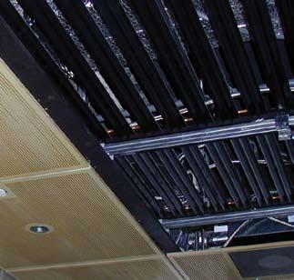
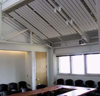
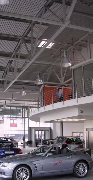
2 General The high capacity Radiant Cooling Module BRM is based on the principles of the radiant cooling technology. Due to the purpose designed profile and the geometry of the unit an increase of convective cooling capacity is achieved. Even at the highest cooling capacity the comfort is never jeopardised, in fact, the severe standards of DIN 1946 part and SIA concerning the air velocity are strictly observed. Application.1. The Design of the Ceiling Installation Details The BRM can be mounted by using adjustable quick hangers either directly from the building ceiling or suspended from an installed ceiling grid. The weight is ca lb/ft. For the connection of the BRM to the hydraulic system and the connection of the elements in series, all metal flexible bellows type hoses (no oxygen permeability) are available. The flexible hoses are provided with high quality push-on couplings. In order to use the push-on couplings together with the installed armatures a specially designed nipple is available. The BRM unit offers a wide range of applications. It can be installed in offices and conference rooms, as well as in shopping centers and laboratories. The BRM can be used as a spot cooling element or a cooling band arranged in strips or simply as a chilled ceiling. Typical Design The extruded aluminium profile is optimally formed to accomodate the copper tube and to provide two cooling fins which are rounded off at the outer end. The surface is black anodized and can be painted if desired. The profiles are 5 in wide fig..1. The gap between the profiles is 0.6 in. Units up to 10 profiles wide and max. 98 in long can be supplied. Copper tubes 1 mm O.D. are used. The high precision of the tube and the extruded profile safeguard a continuous contact between the two surfaces throughout their entire length, thus creating an optimal heat transfer. The Radiant Cooling Units BRM are assembled in the works to form an element ready for installation and connection to the hydraulic system. (fig..) There are numerous possibilities regarding the arrangement of the ceiling.where a metal ceiling is planned or already in existence, the BRM elements can be installed either above the perforated ceiling or directly integrated in the ceiling design. In both applications the thermal storage capacity of the building substance (concrete) can be used. If there is no metal ceiling planned the BRM can be installed directly below the concrete ceiling to represent an architecturally pleasing arrangement. Dimensions Fig..3 shows the unit width in inches and the active area in ft for different length and numbers of profiles Number of Profiles ; Width 3 of Module (in) 30 3 ; ; ; ; ; ; ; ; Active Area of the Module (ft²) Length of Module (in)
3 How to Determine the Standard Cooling Capacity Fig. 3.1 shows the cooling capacity line, determined in accordance with the FGK standards, part KD1 as well as the DIN 4715 standards part 1, as a function of the mean temperature difference t m.the standard cooling capacity is related to an application with the following conditions:. a room height of 3.3 ft. 30% active area. the BRM installed 8 in below the concrete ceiling. an asymmetric arrangement of heat sources in the room. thermal storage capacity of the building substance must not be considered. the copper tube diameter is 1 mm How to Determine the Mean t m: t m = t R (( t WI + t WO )*0.5) t m = mean temperature difference R t R = room air temp. F (dry bulb) t WI = temperature water inlet F t WO = temperature water outlet F Whenever the temperature difference between room air and water outlet temperature is very small, one has to use the logarithmic instead of the arithmetic average temperature difference between room air and water outlet temperature t m = (t WO - t WI)/ln ((t R - t WI)/(t R - t WO )) Applications The influence of the ceiling coverage on the capacity is calculated with the following formula: q B = q* f B q B = specific cooling capacity at the calculated ceiling coverage q = specific cooling capacity as shown in diagram fig. 3.1 = correction factor f B Ceiling coverage in % Factor f H 0% % % % % % % % Cooling Capacity based on the Active Area (Btu/h*ft²) Whenever a metal ceiling (50% free area) at a distance of ca. 4 to 8 in is installed below the BRM, the capacity has to be reduced by the factor f Dd = Mean Temperature Difference Δtm ( R) (Room Air Temp. - Average Chilled Water Temp.) 3
4 How to Determine the Pressure Loss of the Copper Tube 1 mm Dia The diagram in fig. 4.1 shows the resistance of one aluminium profile with a copper tube of 1 mm diameter as a function of the circuit water volume and the length of the profile. In order to determine the total circuit resistance, the value derived from the diagram must be multiplied by the number of BRM and the number of profiles per BRM connected in series and added to the resistance of all flexible hoses in the circuit. p tot = ( p 1 * n U* n P ) + p C p tot = total resistance of the circuit p 1 = resistance of one profile according to diagram 4.1 n U = number of BRM in series n P = number of profiles on each BRM p C= resistance of the flexible connectors, as indicated in the section Hydraulic Minimum Water Flow In order to obtain turbulent flow conditions the water quantity of the circuit should not be below 0 gal/h for the 1 mm tube. This can be achieved by connecting the necessary number of panels in series. In situations where turbulent flow can not be achieved, the specific cooling capacity must be corrected accordingly. 4.1 Resistance of One Heat Conducting Rail (psi) Length of Heat Conducting Rail (in) Water Quantity (gal/hr)
5 Hydraulic Circuits When planning the chilled water distribution it is preferable that the water circulation through the active area is from the window area to the centre of the room. Due to the large tube cross section used on the modules it is possible to connect all modules of one zone in series. This means that only the first and the last module of the zone must be connected to the mains. The water connections to the mains are in accordance with the room or zone layout. Large rooms or large zones active areas should ideally have the same number of modules in series (equal water distribution). In cases where this is not possible the individual water circuits must be adjusted with appropriate throttling devices, see fig. 5.1 pos.1. Generally it is recommended that the individual water circuits of the active areas should be isolated from the mains by means of a ball type valve on the water inlet and outlet branch, see fig. 5.1 (Pos. 3 and 4). The advantages of this method are particularly useful during commissioning work or where alterations have to be made at a later date. During commissioning, the main water installation can be pressure and leak tested with closed ball valves and changes in an active zone can be done without draining the complete system. The control valves regulate the water quantity in the active zone dependent on the cooling requirements. An inline valve is sufficient for most applications. For further information see section Controls in this brochure. For the connection of the BRM to the mains inlet and outlet as well as the inter connection of the BRM in series, all metal flexible bellows type hoses are available, see fig. 5.1 (Pos. 5 and 6). No oxygen can permeate through the all metal flexible hoses into the chilled water. The flexible hoses are provided with high quality push-on couplings. In order to use the push-on couplings together with the installed armatures a specially designed nipple is available, see Fig. 5.1 (Pos. 4) water volume distribution valve control valve 3 ball-type isolating valve with/without air vent/draining valve 4 nipple hose with push-on couplings with push-on couplings 5


 is pushed in the direction of the coupling (disengaging the segment ring) and the flexible hose can be pulled off the copper tube.")

6 Details of Hydraulic Components Control of Chilled Ceilings Fig. 6.1 shows the flexible all metal bellows type hose with push-on couplings at both ends. No oxygen can permeate through the hose into the chilled water circuit. Technical Data of the All Metal Hose stainless steel material code push-on coupling: Legris DN 1 max. operating pressure: 130 psi dimensions: DN 10 x 40 in long Cv - value 1.13 How to Calculate the Resistance of One Hose When fitting the push-on coupling onto the copper tube end, the unit is lined up with the tube and using light pressure, pushed in the direction of the tube until it has reached the tube stop. When dismantling, the release ring (3) is pushed in the direction of the coupling (disengaging the segment ring) and the flexible hose can be pulled off the copper tube. Attention: The coupling must only be disconnected after the zone pipework has been drained. given: all metal flexible hose Cv-value = 46.7 ft3/h, L=39.7 inch, DN=10, bend 180, water volume m= 1.13 gal/h Fig. 6.3 shows the screw-in nipple which can be tightened and screwed into the 1/ BSP thread of the isolating valve using appropriate sealing materials. The stud is machined (1 mm dia.) to receive the push-on coupling of the connecting hose. The nipple can be used on both sides, the water inlet and outlet. UNKNOWN: Resistance p p= (m/cv)x100 = (1.13/46.7)x100 = 0.85 Pa Fig. 6. shows the push-on coupling which has been specially designed for use with chilled ceilings. The seal is achieved by means of a double profile ring. The coupling hooks on to the copper tube using a segment ring made of stainless spring steel. The advantage of this push-on coup- ling is found in a very simple, reliable connection and disconnection as well as in the superb production quality. To balance the water quantity of the different active zones, standard balancing valves with connectors for measuring equipment can be installed. With regard to control valves, see section Controls bellows type hose push-on coupling 3 segment ring made of stainless steel 3 dismantling release ring 6 Where variable internal and external heat loads prevail, the cooling output of a chilled ceiling is varied with the aid of a simple room controller. Normal control is achieved by throttling the water flow. The relatively small water content and the optimal selection of the material used on the BRM ensure a fast reaction to any changes in heat load. The resulting control characteristics are comparable with those achieved with air systems. Normally the algorithm PI-reaction is selected with a proportional band of l.8 R and an integral time of 10 minutes. Using such control, large heat load changes can be corrected quickly with stable results. An unintentional drift of the room air temperature, which would negatively influence comfort does not therefore occur. In order to achieve a stable control circuit, the correct sizing of the control valve is important. It is recommended that the valve authority is between 0.5 and 1. This means that the pressure drop, when the valve position is fully open, is equivalent to factor of the pressure drop calculated for the zone circuit. To avoid sedimentation it is recommended not to install valves with Cv values smaller than 35 ft 3 /h. In zones where more than one control valve is installed, care should be taken that all valves operate in parallel. 6.3

7 7.1 N zone controller B1 room temperature sensor B dew point sensor B Y1 Y1 Y1 chilled water valve Y heating valve Commissioning Pressure Testing Like all hydraulic systems used in buildings, the chilled ceiling systems must be tested for possible leaks and tested to withstand the working pressure. These tests must be done prior to commissioning, observing the local rules and regulations. heating 100 % 0 % - room air temperature + 7. cooling valve shut when saturation point is reached data line from previous rooms To avoid condensation, the chilled water temperature must always remain above the dew point of the room air. This must be achieved by the consequent control of the chilled water flow temperature. To eliminate any possibility of condensation, it is recommended to install a dew point sensor into each zone as a safety precaution. Prior to N B1 t Y data line to the following room reaching critical saturation, the sensor would react and as a result the control valve would prohibit any water circulation in the zone. Y Operational Testing To achieve correct operation of the BRM, the system must be carefully vented. Furthermore, proof of water flow through all pipe work including the BRM tubes is essential. The use of modern infra-red camera systems with image recording capacity provides a professional solution. The infra-red image print-out should be part of the commissioning manual. Fig. 7. shows a typical thermal image of BRM units in operation installed above a metal ceiling with 50% free area. 7
8 Contacts Headquarters Barcol-Air Ltd. 115 Hurley Road Oxford, CT Phone: (03) Fax: (03) Website: Barcol-Air Ltd. Georgetown Center, Building B 5963 Coreson Avenue South Seattle, WA Seattle@barcolairusa.com Website: Your partner for radiant cooling and heating, chilled beams and VAV systems.
BARCOL-AIR RADIANT WAVE (BRW) Your Wave Radiant Cooling or Heating RADIANT WAVE
 Your Wave Radiant Cooling or Heating RADIANT WAVE") BARCOL-AIR (BRW) Your Wave Radiant Cooling or Heating Table of Contents Page Table of Contents 2 General Description 3 Materials 3 Areas of Applicatoin 4 Dimensions 4 Cooling Capacities 5 Heating Capacities
BARCOL-AIR (BRW) Your Wave Radiant Cooling or Heating Table of Contents Page Table of Contents 2 General Description 3 Materials 3 Areas of Applicatoin 4 Dimensions 4 Cooling Capacities 5 Heating Capacities
Two-port valves, male threaded, PN25
 4 379 Two-port valves, male threaded, PN25 VVG55... Two-port valves, externally threaded, PN25 Bronze Rg5 DN15... 25 mm (½"... 1") k vs 0.25... 6.3 m 3 /h Stroke 5.5 mm Suitable for type SQS35... or SQS65...
Air Operated Hydraulic Pumping Systems to 50,000 psi
 High Pressure Equipment Air Operated Hydraulic Pumping Systems to 50,000 psi PS-10: 10,000 psi PS-20: 20,000 psi PS-30: 30,000 psi PS-40: 40,000 psi PS-50: 50,000 psi PS-90: 90,000 psi High Pressure air
Instruction Manual. Pipe Friction Training Panel
 Instruction Manual HL 102 Pipe Friction Training Panel 100 90 80 70 60 50 40 30 20 10 HL 102 Instruction Manual This manual must be kept by the unit. Before operating the unit: - Read this manual. - All
SIMPLAIR PIPING TOOL. JXT Company
 SIMPLAIR PIPING INGERSOLL-RAND SIMPLAIR PIPING With push-in fittings and lightweight anodized aluminum pipe, a SimplAir system provides ideal connection throughout your entire air distribution system.
Installation and commissioning instructions 255 series and 256 series
 Installation and commissioning instructions 255 series and 256 series Table of contents 1 General information... 3 1.1 About these instructions... 3 1.2 About this product... 3 1.3 Appropriate usage...
Function. size 1-¼ inch: 9-¾" size 1-½ inch: 11-¼" size 2 inch: 12-¾" A A A A A/96A A/99A
 Hydro separator CLEI 0076/6 N CCREDITED Replaces 0076/4 N ISO 900 No. 000 ISO 900 M 2654 unction The Caleffi 548 and N hydraulic separator creates a zone with a low pressure loss, which enables connected
Bermad Pressure Reducing. Model: 42T
 Bermad Pressure Reducing Pilot Operated Pressure Control Valve Model: 42T Installation Operation Maintenance Manual (IOM) REV. 27.7.17 Page 1 of 12 Safety First BERMAD believes that the safety of personnel
COMPRESSED AIR DISTRIBUTION SYSTEMS
 Series COMPRESSED AIR DISTRIBUTION SYSTEMS 18 DESIGNING AN EFFICIENT COMPRESSED AIR DISTRIBUTION The main source of inefficiencies and problems affecting compressed air distribution systems is often the
V43 Pressure Actuated Water Regulating Valve
 FANs 125, 121 Product/Technical Bulletin V43 Issue Date 0996 V43 Pressure Actuated Water Regulating Valve The V43 Pressure Actuated Water Regulating Valves are designed to regulate water flow for water-cooled
Standard Operating and Maintenance Instructions for Pumping System Model PS-90
 Standard Operating and Maintenance Instructions for Pumping System Model PS-90 High Pressure Equipment Company 2955 West 17th Street, Suite 6 PO Box 8248 Erie, PA 16505 USA 814-838-2028 (phone) 814-838-6075
Shut-off valve Type QDV
 Data sheet Shut-off valve Type QDV QDV is a shut-off valve, designed particularly for draining oil from systems containing refrigerant (ammonia) under pressure. The valve will close immediately on release
Rapidmain Installation Guide
 Rapidmain Installation Guide Aluminium Compressed Air Pipe Work Installation Guide Trafalgar Court, Waterloo Ind Estate, Widnes Cheshire. UK. Ref: Rapidmain installation guide 4b Index 1. Rapidmain fittings:
Radiator thermostats type RA2000, valve bodies type RA-FN (series D) and RA-G
 and RA-G") Data sheet Radiator thermostats type RA2000, valve bodies type RA-FN (series D) and RA-G EN 215 Application RA2000 013G2910 Built-in sensor RA2000 013G2920 tamperproof RA2000 013G5062 remote temperature
Data sheet Radiator thermostats type RA2000, valve bodies type RA-FN (series D) and RA-G EN 215 Application RA2000 013G2910 Built-in sensor RA2000 013G2920 tamperproof RA2000 013G5062 remote temperature
Pneumatic proportional controller Types M Types FM Function tested for use of the float in Ex-zone 0
 Operating Manual LTIA5E Pneumatic proportional controller Types M Types FM Function tested for use of the float in Ex-zone 0 Contents 1. Safety Instructions 2. Conformity to standards 3. Technical data
Differential Pressure Control Valve. Passim
 Differential Pressure Control Valve Passim 2 Table of contents Chapter Nexus Valve Passim DN 15-50, DN 65-80 1. Safety instructions 4 1.1 Rules/regulations 4 1.2 Intended use 5 1.3 Initial operation 5
Versions. Benefits. Balancing DN15-32 DN40 DN50 DN15, DN20, DN25, DN32, DN40, DN50. Dimensions
 Ballorex Delta Description The Ballorex Delta is a differential pressure control valve used in hydronic heating or cooling systems. By ensuring a constant differential pressure across motorized or static
MSC-P and MSC-N Manifolds for Steam Distribution and Condensate Collection
 1170850/1 IM-P117-36 ST Issue 1 MSC-P and MSC-N Manifolds for Steam Distribution and Condensate Collection Installation and Maintenance Instructions 1. Safety information 2. General product information
Mounting and operating instructions EB 2530 EN. Self-operated Pressure Regulator. Pressure Reducing Valve Type M 44-2
 Self-operated Pressure Regulator Pressure Reducing Valve Type M 44-2 Type M 44-2, connection G 1 4, K VS = 0.15 Type M 44-2, connection G 1, K VS = 6 Fig. 1 Type M 44-2 Pressure Reducing Valve Mounting
Data Sheet Issue A
 Features 1. Differential latching clappertype, lighweight, dependable construction. 2. Low Air Pressurized System, 8 psi -to- 26 psi (0,6 bar to- 1,8 bar) 3. Reset externally. Cover removal is not required.
Quick closing oil drain valve, type QDV 15 REFRIGERATION AND AIR CONDITIONING. Technical leaflet
 Quick closing oil drain valve, type QDV 15 REFRIGERATION AND AIR CONDITIONING Technical leaflet Introduction QDV is a quick closing oil drain valve, designed particularly for draining oil from systems
MST21 Stainless Steel Balanced Pressure Thermostatic Steam Trap
 1250650/6 IM-P125-07 ST Issue 6 MST21 Stainless Steel Balanced Pressure Thermostatic Steam Trap Installation and Maintenance Instructions 1. Safety information 2. General product information 3. Installation
Model 7989T Steel Pipe Squeezer Sch. 40 & Sch. 80. Operations Manual
 10-12 Steel Pipe Squeezer Sch. 40 & Sch. 80 Operations Manual 1.0 Introduction This manual is issued as a basic operation manual covering the Regent Model 7989T, Pipe Squeezer and Pump as manufactured
Valve Proving System VDK 200 A S06*
 Valve Proving System VDK 200 A S06* Valve proving system with the following approvals. UL Recognized File # MH17004 CSA Certified File # 1637485 CSA Requirement No. 4-01 (USA) Technical Information Letter
Horizontal Bladder Tanks
 DATA SHEET Horizontal Bladder Tanks Features UL Listed and FM Approved for use with various ANSUL proportioners and foam concentrates 175 psi (12.1 bar) maximum allowable working pressure (design pressure)
USM21 Sealed Bimetallic Steam Trap for use with Pipeline Connectors Installation and Maintenance Instructions
 6250250/1 IM-P625-03 ST Issue 1 USM21 Sealed Bimetallic Steam Trap for use with Pipeline Connectors Installation and Maintenance Instructions 1. General safety information 2. General product information
Krantz Components. Multifunction sail AVACS. Cooling and heating systems
 Multifunction sail AVACS Cooling and heating systems DS 4170 E 01.2014 Preliminary remarks and construction design Preliminary remarks The multifunction sail AVACS is designed for use with plane metal
Pressure Dump Valve Service Kit for Series 2300 Units
 Instruction Sheet Pressure Dump Valve Service Kit for Series 00 Units. Overview The Nordson pressure dump valve is used to relieve hydraulic pressure instantly in Series 00 applicator tanks when the unit
TA10A and TA10P Steam Tracing Temperature Control Valves Installation and Maintenance Instructions
 3500032/2 IM-P350-02 CH Issue 2 TA10A and TA10P Steam Tracing Temperature Control Valves Installation and Maintenance Instructions 1. Safety information 2. General product information 3. Installation 4.
AIR COMPRESSOR MANUAL INSTALLATION, OPERATION AND MAINTENANCE GUIDE
 AIR COMPRESSOR MANUAL INSTALLATION, OPERATION AND MAINTENANCE GUIDE 1. DESCRIPTION The compressor is a reciprocating air pump mounted on and driven by an electric induction motor. Mounted on a sturdy frame
HORNE T109A/306A/307A THERMOSTATIC SHOWER VALVE FOR SURFACE MOUNTING WITH TIMED FLOW CONTROL INSTALLATION, OPERATION & MAINTENANCE INSTRUCTIONS
 Horne Engineering Ltd PO Box 7, Rankine Street Johnstone, PA5 8BD Tel: +44 (0)1505 321455 Fax: +44 (0)1505 336287 Email: Technical@horne.co.uk Web: www.horne.co.uk HORNE T109A/306A/307A THERMOSTATI SHOWER
Ball valve HKSF-W100. Ball valve HKSF-W100. RMA Kehl GmbH & Co. KG Oststrasse 17 D Kehl / Germany
 Ball valve HKSF-W100 RMA Kehl GmbH & Co. KG Oststrasse 17 D-77694 Kehl / Germany info@rma-kehl.de www.rma-armaturen.de 1 Design Features: RMA-ball valves type HKSF-W are fully welded and completely maintenance-free
Series V48. 3-Way Pressure Actuated Modulating Valves. Product Bulletin. Features. Pressure balanced design. Free movement of all parts
 Series V48 -Way Pressure Actuated Modulating Valves Product Bulletin These Water Valves are especially designed for condensing units cooled either by atmospheric or forced draft cooling towers. They may
A3S Bellows Sealed Stop Valve Installation and Maintenance Instructions
 1326050/3 IM-P132-11 ST Issue 3 A3S Bellows Sealed Stop Valve Installation and Maintenance Instructions 1 General safety information 2 General product information 3 Installation 4 Commissioning 5 Operation
2-port seat valves PN25 with externally threaded connections
 4 379 2-port seat valves PN25 with externally threaded connections VVG55.. Valve body bronze CC491K (Rg5) DN 15...25 (½...1 ") kvs 0.25...6.3 m3/h Stroke 5.5 mm Sets of ALG.. with threaded and ALS.. with
Differential pressure controller (PN 16) AVPL return mounting, adjustable setting
 AVPL return mounting, adjustable setting") Data sheet Differential pressure controller (PN 16) AVPL return mounting, adjustable setting Description It can be used on primary side of house substations for smaller systems such as one and two-family
Data sheet Differential pressure controller (PN 16) AVPL return mounting, adjustable setting Description It can be used on primary side of house substations for smaller systems such as one and two-family
Radiator thermostats type RA2000, valve bodies type RA-FN (series D) and RA-G
 and RA-G") Data sheet Radiator thermostats type RA2000, valve bodies type RA-FN (series D) and RA-G Application RA2000 013G2910 Built-in sensor RA2000 013G2920 tamperproof RA2000 013G5062 remote temperature adjuster
Data sheet Radiator thermostats type RA2000, valve bodies type RA-FN (series D) and RA-G Application RA2000 013G2910 Built-in sensor RA2000 013G2920 tamperproof RA2000 013G5062 remote temperature adjuster
SCA Series Inverted Bucket Steam Traps
 0770050/5 IM-P077-06 ST Issue 5 SCA Series Inverted Bucket Steam Traps Installation and Maintenance Instructions 1. General safety information 2. General product information 3. Installation 4. Commissioning
HM and HM34 Inverted Bucket Steam Traps Installation and Maintenance Instructions
 0670350/4 IM-S03-11 ST Issue 4 HM and HM34 Inverted Bucket Steam Traps Installation and Maintenance Instructions 1. Safety information 2. General product information HM Series 3. Installation 4. Commissioning
Pressure Dump Valve Service Kit for Series 3000 Units
 Instruction Sheet Pressure Dump Valve Service Kit for Series 000 Units. Overview The Nordson pressure dump valve is used to relieve hydraulic pressure instantly in Series 00, 400, 500, and 700 applicator
Series V47 Temperature Actuated Modulating Valves
 PSC0302 European Refrigeration Controls Catalogue Catalog Section 7 Product Bulletin V47 Series V47 Temperature Actuated Modulating Valves Introduction The V47 modulating water valves regulate the flow
Remeha Quinta Cascade guide
 Technical information Remeha Quinta Cascade guide Cascade guide Cascade systems 2 Remeha Quinta Cascade guide TABLE OF CONTENTS FOREWORD 4 1 GENERAL DESCRIPTION OF CASCADE SYSTEMS 4 1.1 Optimum number
Model DDX-LP Dry Pipe Valve System 8 (200mm) Features. Differential latching clapper-type, lighweight, dependable construction.
 Features. Differential latching clapper-type, lighweight, dependable construction.") Bulletin 335 Model DDX-LP Dry Pipe Valve System 8 (200mm) Bulletin 335 Features 1. 2. 3. 4. 5. 6. 7. 8. 9. 10. 11. 12. Differential latching clapper-type, lighweight, dependable construction. Low Air Pressurized
Bulletin 335 Model DDX-LP Dry Pipe Valve System 8 (200mm) Bulletin 335 Features 1. 2. 3. 4. 5. 6. 7. 8. 9. 10. 11. 12. Differential latching clapper-type, lighweight, dependable construction. Low Air Pressurized
Vertical and Horizontal Bladder Tanks
 DATA SHEET Vertical and Horizontal Tanks Application The ANSUL bladder tank is one component in a balanced pressure proportioning system. Its operation requires no external power other than a pressurized
Simple Set. Pressure Independent Control Valves 2 Way 1/2-2
 The Bray Simple Set is a threaded pressure independent control (PIC) valve designed for a wide variety of hot water and chilled water control applications. The SS Series combines high rangeability control
Krantz Components. Multifunction Sail AVACS. Cooling and Heating Systems
 Multifunction Sail AVACS Cooling and Heating Systems 2 AVACS Air Ventilation And Cooling System 3 System design Air diffuser box Air connection Sound absorbers (optional) Cooling element with heat conducting
UIB30 and UIB30H Sealed Inverted Bucket Steam Traps for use with Pipeline Connectors
 1130050/4 IM-P113-02 ST Issue 4 UIB30 and UIB30H Sealed Inverted Bucket Steam Traps for use with Pipeline Connectors Installation and Maintenance Instructions 1. Safety information 2. General product information
Propane Conversion Kit Instruction
 Propane Conversion Kit Instruction Condensing gas boiler Required Input Rates Logamax plus GB62-80 kw 270,000 btu/hr Logamax plus GB62-00 kw 35,000 btu/hr This kit and instructions are for converting the
Series Environmental Chambers
 3119-600 Series Environmental Chambers Challenges in Non-Ambient Testing Testing at non-ambient temperatures adds another layer of challenges to your testing laboratory. Ensuring you get accurate and stable
Vertical Bladder Tanks
 DATA SHEET Vertical Bladder Tanks Features UL Listed and FM Approved for use with various ANSUL proportioners and foam concentrates 175 psi (12.1 bar) maximum allowable working pressure (design pressure)
Automatic Balancing Valve Pressure difference controller with integrated flow limiter AB-PM DN
 Data sheet Automatic Balancing Valve Pressure difference controller with integrated flow limiter AB-PM DN 40-100 Description AB-PM is ideal for staged installation and commissioning AB-PM is a combined
Evolution. Radiant Panels. Radiant panel system LPHW up to 90 C Suspended ceiling grid or sofit mounting Vertical wall surface mounting
 Evolution Radiant Panels Radiant panel system LPHW up to 90 C Suspended ceiling grid or sofit mounting Vertical wall surface mounting Contents IDENTIFICATION DESCRIPTION Page STYLE CG 3-7 STYLE CS, FC
BTM7, BTS7 and BTS7.1 Stainless Steel Thermostatic Clean Steam Traps
 1801050/10 IM-P180-05 ST Issue 10 BTM7, BTS7 and BTS7.1 Stainless Steel Thermostatic Clean Steam Traps Installation and Maintenance Instructions 1. Safety information 2. General product information 3.
Instruction Manual. Standard Surge Eliminator. Standard X. Flushable X - X
 Standard Surge Eliminator Standard 104052 - X Flushable 104053 - X - X Page 2 of 16 Issue: 2.3 Index Section 1.1 General Description 1.2 Operating Principle 1.3 Specification 1.4 Fitting Selection - Standard
TD45 Thermodynamic Steam Trap Installation and Maintenance Instructions
 0685255/1 IM-P068-47 ST Issue 1 TD45 Thermodynamic Steam Trap Installation and Maintenance Instructions 1 General safety information 2 General product information 3 Installation 4 Commissioning 5 Operation
I T T Pressure Reducing Valve WARNING INSTALLATION, OPERATION, AND MAINTENANCE MANUAL
 INSTALLATION, OPERATION, AND MAINTENANCE MANUAL I-867-4T 867-4T Pressure Reducing Valve HANG THESE INSTRUCTIONS ON THE INSTALLED VALVE FOR FUTURE REFERENCE WARNING Read and understand all instructions
COMPACT TRIPLE WALL OUTLET STATION MODEL INSTALLATION AND OPERATING INSTRUCTIONS
 COMPACT TRIPLE WALL OUTLET STATION MODEL 6255-1 INSTALLATION AND OPERATING INSTRUCTIONS To assure safe operation and conformation to local fire codes, all Porter Outlet Stations are designed to be used
HIGH FLOW HIGH PRESSURE PUMP type BMS
 When you have to test objects on different locations within your workshop, the mobile pump system BMS gives you the possibility to test adequately on different sites. Through its wheels (or forklift pockets)
LindabSolus. Supply air beam. lindab we simplify construction
 lindab we simplify construction Lindab 03.2016 Lindab Ventilation. All forms of reproduction without written permission are forbidden. is the registered trademark of Lindab AB. Lindab's products, systems,
Universal Charging and Testing Unit FPU-1
 1. DESCRIPTION 1.1. FUNCTION The charging and testing unit FPU-1 is used to charge accumulators with nitrogen or to check or to change the existing pre-charge pressure in accumulators. For this purpose
LindabPremax. Supply air beam. lindab we simplify construction
 lindab we simplify construction Lindab 03.2016 Lindab Ventilation. All forms of reproduction without written permission are forbidden. is the registered trademark of Lindab AB. Lindab's products, systems,
Regulating valves REG-SA and REG-SB
 MAKING MODERN LIVING POSSIBLE Technical brochure Regulating valves REG-SA and REG-SB REG-SA and REG-SB are angleway and straightway hand regulating valves, which act as normal stop valves in closed position.
DS MZ, MZF, MJF THREE-PORT SEAT VALVES
 DS 4.610 11/99, F, THREE-PORT SEAT VALVES Specification No. 626-3-XXX These seat valves are of 'globe' construction with a linear moving spindle and a modified parabolic characterised plug operating against
AIR DISTRIBUTOR. PART NUMBER (Including, but not inclusive) AD28483-_ALB, AD28563-_ALB, AD36097-_ALB, AD36098-_ALB, AD28485-_ALB
 AD28483-_ALB, AD28563-_ALB, AD36097-_ALB, AD36098-_ALB, AD28485-_ALB") Manual #: MM-AD001 12/5/11 Rev. A Page 1 of 8 PART NUMBER (Including, but not inclusive) AD28483-_ALB, AD28563-_ALB, AD36097-_ALB, AD36098-_ALB, AD28485-_ALB Manual #: MM-AD001 12/5/11 Rev. A Page 2 of
Manual #: MM-AD001 12/5/11 Rev. A Page 1 of 8 PART NUMBER (Including, but not inclusive) AD28483-_ALB, AD28563-_ALB, AD36097-_ALB, AD36098-_ALB, AD28485-_ALB Manual #: MM-AD001 12/5/11 Rev. A Page 2 of
PRESSURISED PAINT CONTAINER
 PRESSURISED PAINT CONTAINER MODEL NO: CPP2B PART NO: 3082115 OPERATION & MAINTENANCE INSTRUCTIONS GC0913 INTRODUCTION Thank you for purchasing this CLARKE Pressurised Paint Container. Before attempting
Data Sheet Issue A
 Features 1. Differential-type valve, lightweight, dependable construction. 2. Low Air Pressurized System, 10 psi -to- 26 psi (0,7 bar -to- 1,8 bar). 3. Reset externally.cover removal is not required. 4.
Installation, Operation and Maintenance Instructions for Pacific PA Non-Storage Heat Exchanger
 OM008 Installation, Operation and Maintenance Instructions for Pacific PA Non-Storage Heat Exchanger The operating and maintenance instructions contained within this package are for Pacific water/water
LindabPremum. Supply air beam. lindab we simplify construction
 lindab we simplify construction Lindab 03.2016 Lindab Ventilation. All forms of reproduction without written permission are forbidden. is the registered trademark of Lindab AB. Lindab's products, systems,
Spiratec ST14, ST16 and ST17 Sensor Chambers and sensors
 0862050/1 IM-P086-18 MI Issue 1 Spiratec ST14, ST16 and ST17 Sensor Chambers and sensors Installation and Maintenance Instructions 1. Safety Information 2. General product information 3. Installation 4.
GM Series Dual-Block Multi-Function Gas Control Valves
 Installation Sheets Manual 121 Gas Combustion Combination Controls and Systems Section G Technical Bulletin GM Issue Date 0297 GM Series Dual-Block Multi-Function Gas Control Valves Figure 1: GM Series
product manual HM-4140, HM-4150, HM-4160 HM-4160A HM-4150 Humboldt FlexPanels
 12.09 product manual HM-4140, HM-4150, HM-4160 HM-4160A HM-4150 Humboldt FlexPanels Introduction: This manual covers the installation and operation of Humboldt FlexPanels for Triaxial and Permeability
UBP32 Sealed Balanced Pressure Thermostatic Steam Trap for use with PC_ Pipeline Connectors Installation and Maintenance Instructions
 1270750/7 IM-P127-02 ST Issue 7 UBP32 Sealed Balanced Pressure Thermostatic Steam Trap for use with PC_ Pipeline Connectors Installation and Maintenance Instructions 1 General safety information 2 General
SEALED CONNECTORS FOR THE LIMIT SWITCHES
 SEALED CONNECTORS FOR THE LIMIT SWITCHES LIST OF MODELS / Sealed connectors are used at the cable-connecting section of limit switches. Type and appearance Materials Features Target market Applications
Features. Model DDX-LP Dry Pipe Valve System 4 (100mm), 6 (150mm) & 165mm Sizes
, 6 (150mm) & 165mm Sizes") Bulletin 357 Rev. E Model DDX-LP Dry Pipe Valve System 4 (100mm), 6 (150mm) & 165mm Sizes Bulletin 357 Rev. E Features 1. 2. 3. 4. 5. 6. 7. 8. 9. Differential-type valve, lightweight, dependable construction.
Bulletin 357 Rev. E Model DDX-LP Dry Pipe Valve System 4 (100mm), 6 (150mm) & 165mm Sizes Bulletin 357 Rev. E Features 1. 2. 3. 4. 5. 6. 7. 8. 9. Differential-type valve, lightweight, dependable construction.
Model MTB-ASME Vertical Bladder Tanks
 DATA SHEET Model MTB-ASME Vertical Bladder Tanks Features n UL Listed for use with various proportioners and foam concentrates n 175 psi (12.1 bar) maximum allowable working pressure (design pressure)
HANDBOOK. Squeeze Off Unit SOU 400. Please refer any queries to:
 HANDBOOK Squeeze Off Unit SOU 400 Please refer any queries to: Hy Ram Engineering Co Ltd Pelham Street Mansfield Nottinghamshire NG18 2EY Telephone No: (01623) 422982 Please note all queries should state
MZX. Three-Port Seat Valves SPECIFICIATIONS AND GUIDE TO SELECTION
 01 These seat valves are of globe construction with a linear moving spindle and a modified parabolic characterised plug operating against the upper seat which controls flow quantity to suit the load. The
AIR DRIVEN. Gas Boosters & SYSTEMS. Accepting VISA, MasterCard and American Express
 AIR DRIVEN Gas Boosters & SYSTEMS Accepting VISA, MasterCard and American Express Gas Boosters AIR DRIVEN FROM 30 PSI TO 21,750 PSI MAXIMATOR Maximator gas boosters are an excellent alternative to high
SUMMARY PROBLEMS CAUSED BY BACKFLOW IN PIPE SYSTEMS.
 Page 1 of 11 SUMMARY There are many problems derived from a reverse flow in a piping system. A solution presented in this paper is the WaStop inline check valve. The paper aims to explain some of the important
Self-operated Regulators Accessories Differential Pressure and Flow Regulators
 Self-operated Regulators Accessories Differential Pressure and Flow Regulators Compression-type fittings Needle valves Compensation chambers Orifice plates Welding neck flanges Control lines Application
130400A 1/2 NPT Female A 3/4 NPT Female A 1 NPT Female A 1 1/4 NPT Female A 1 1/2 NPT Female A 2 NPT Female
 88.0A www.caleffi.com Venturi Style Balancing Valve Copyright 0 Caleffi 0 Series Function Product Range Balancing valves are hydraulic devices that can precisely control the flow rate of the fluid that
Operating Instructions Part No
 DIGITAL AUTOMATIC TYRE INFLATOR Operating Instructions Part No. 11.0545 Thank you for selecting this Jamec Pem Automatic Tyre Inflator. Please read this manual before carrying out any installation or service
Model MTB-ASME Horizontal Bladder Tanks
 DATA SHEET Model MTB-ASME Horizontal Bladder Tanks Features n UL Listed and FM Approved for use with various proportioners and foam concentrates n 175 psi (12.1 bar) maximum allowable working pressure
Model MTB-ASME Vertical Bladder Tanks
 DATA SHEET Model MTB-ASME Vertical Bladder Tanks Features n UL Listed for use with various proportioners and foam concentrates n 175 psi (12.1 bar) maximum allowable working pressure (design pressure)
STA-F Description. STA-F Prefab insulation Measuring nipples
 TA STA-F 5-5-1 5 Balancing valves September 1985 STA-F is a flanged balancing valve available in sizes DN 20-300, and has been designed with an oblique seat in order to give low resistance and large flows
Technical Data Sheet T 2025
 Self-operated emperature Regulators emperature Regulator ype 4 Valve closes when the temperature rises. emperature Regulator ype 4u Valve opens when the temperature rises. Balanced single-seated globe
Modulating liquid level regulators, direct-controlled, type SV 1 and 3 REFRIGERATION AND AIR CONDITIONING. Technical leaflet
 Modulating liquid level regulators, direct-controlled, type SV 1 and 3 REFRIGERATION AND AIR CONDITIONING Technical leaflet Contents Page Introduction...3 Technical data...3 Approvals...3 Identification...3
Pneumatic switch module 3/2-way valve (On/Off) Types P Types FP Function tested for use of the float in Ex-zone 0
 Types P Types FP Function tested for use of the float in Ex-zone 0") Operating Manual LTIA3E Pneumatic switch module 3/2-way valve (On/Off) Types P Types FP Function tested for use of the float in Ex-zone 0 Contents 1. Safety Instructions 2. Conformity to standards 3. Technical
Operating Manual LTIA3E Pneumatic switch module 3/2-way valve (On/Off) Types P Types FP Function tested for use of the float in Ex-zone 0 Contents 1. Safety Instructions 2. Conformity to standards 3. Technical
Float valves Types SV 4, SV 5 and SV 6
 Data sheet Float valves Types SV 4, SV 5 and SV 6 SV 4-6 are for use on the low pressure side as modulating liquid level regulators in refrigeration, freezing and air conditioning systems with ammonia
CSO/STORMWATER MANAGEMENT. HYDROVEX HHV-E Vortex Driven Regulator
 CSO/STORMWATER MANAGEMENT HYDROVEX HHV-E Vortex Driven Regulator HYDROVEX HHV-E VORTEX DRIVEN REGULATOR APPLICATION The hydro electronic HYDROVEX HHV driven regulator, type E is specially designed for
Differential pressure controller (PN 16) AVPL - return mounting, adjustable setting
 AVPL - return mounting, adjustable setting") Data sheet Differential pressure controller (PN 16) AVPL - return mounting, adjustable setting Description It can be used on primary side of house substations for smaller systems such as one and two-family
Data sheet Differential pressure controller (PN 16) AVPL - return mounting, adjustable setting Description It can be used on primary side of house substations for smaller systems such as one and two-family
Connecting hoses. Type FS. Connecting hoses for the water-side connection of air- water systems and decentralised ventilation units PD FS 1
 X X testregistrierung Connecting hoses Type G½" external thread and flat seal G½" union nut and flat seal Connecting hoses for the water-side connection of air- water systems and decentralised ventilation
VALVES HIDROMATIC VALVE.
 VALVES HIDROMATIC VALVE Hydrodynamic design The Hidromatic valve of Hidroconta is a piston hydraulic valve controlled with the same fluid of the conduction. Its balloon design improves its hydrodynamic
Valve Proving System VDK 200 A S02
 Valve Proving System VDK 200 A S02 Valve proving system with the following approvals. UL Recognized File # MH17004 CSA Certified File # 1637485 CSA Requirement No. 4-01 (USA) Technical Information Letter
tubepress press procedure
 tubepress press procedure tubepress 15mm up to 35mm tubepress 15 mm up to 35 mm 1. The tube ends must be clean with no scratches or grooves. Remove end caps. Cut tube to length. 2. Deburr tube inside and
COMPRESSION TUBE FITTINGS
 COMPRESSION TUBE FITTINGS 1/16 THROUGH 2 2 MM THROUGH 50 MM LET-LOK TUBE FITTINGS DESCRIPTION The HAM-LET GROUP has produced high quality tube and pipe fittings in various materials for high pressure applications
Halsey Taylor Owners Manual
 Halsey Taylor Owners Manual Wall Mount Steel Refrigerated Fountains INSTALLER These series fountains are among the easiest to install Fountains on the market today. To assure you install these models easily
differential pressure regulating valve - threaded
 140-142 differential pressure regulating valve - threaded Introduction Differential pressure regulating valves (DPRV) maintain the differential pressure across a circuit or sub-branch at a set differential
Gas powered stop valves, type GPLX REFRIGERATION AND AIR CONDITIONING. Technical leaflet
 Gas powered stop valves, type GPLX 80-150 REFRIGERATION AND AIR CONDITIONING Technical leaflet Technical leaflet Gas powered stop valves, type GPLX 80-150 Contents Page Introduction........................................................................................3
Float valves Types SV 1 and SV 3
 Data sheet Float valves s SV 1 and SV 3 The SV 1 and 3 can be used separately as a modulating liquid level regulator in refrigerating, freezing and air conditioning systems for ammonia or fluorinated refrigerants.