Krantz Components. Multifunction sail AVACS. Cooling and heating systems
|
|
|
- Josephine Andrews
- 6 years ago
- Views:
Transcription

1 Multifunction sail AVACS Cooling and heating systems DS 4170 E
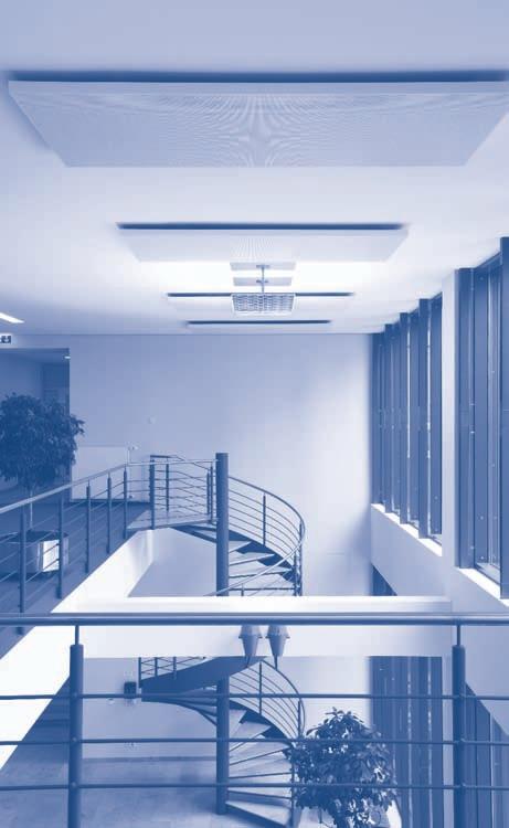
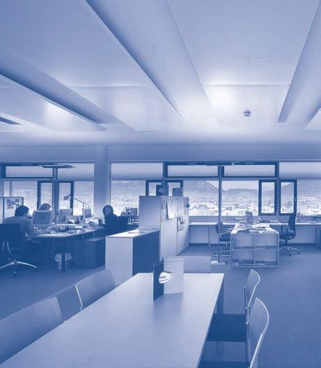
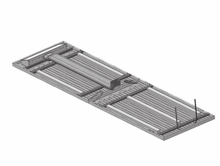
2 Preliminary remarks and construction design Preliminary remarks The multifunction sail AVACS is designed for use with plane metal acoustic sails from various brands to make cooling or heating sails. The large-surface permanent contact between the cooling element and the ceiling panel is preferably done by bonding. AVACS stands for Air Ventilation And Cooling System. The AVACS multifunction sail combines the following functions: cooling, heating, indoor air circulation and sound absorption, which are performed in compliance with thermal comfort criteria. There are a number of configurations available, e.g. made up of one or several pieces rigid or pull-down design with or without supply air distribution optionally with return air extraction optionally fitted with inspection element for maintenance of control valves installed by the client. AVACS multifunction sails come into use in offices, meeting rooms, foyers, exhibition rooms, libraries and such like, and serve to remove medium cooling loads. Construction design A multifunction sail AVACS consists of: one or several perforated metal ceiling panels copper serpentine pipework (copper tube from a coil) with connection ends for water inflow and outflow aluminium heat conducting profiles for fixing the serpentine pipework and creating a large contact surface area to the sail element steel crossbars for suspending the sail element an induction unit an optional return air diffuser. The multifunction sail can be optionally fitted with sound absorbers. The induction unit is fixed to the sail on site using two sheet metal screws (or rivets). As standard it is fitted with an oval spigot for flex duct DN 125. The induction unit discharges about 70% of the supply air above and 30% below the sail, thus circulating a large volume of indoor air and ensuring a continuously comfortable thermal environment. The induction unit has been engineered such that the cooler supply air from outside does not drop as is the case with displacement air outlets, but rather flows almost horizontally along the underside of the AVACS sail as a result of the Coanda effect. The pipework connections are preferably designed for push-in fittings; their shapes and positions are adapted to the required ceiling design and function, e.g. pull-down design lengthwise. For the serpentine pipework we use only quality-controlled copper tube. The sails can incorporate lights, air diffusers, loudspeakers and such like. Fig. 2 shows the structure of a multifunction sail as installed. This sketch suggests that the induction unit is connected to a flex duct, the sail elements are fitted with push-in fittings and flexible hoses, and are grouped, the access to the ceiling plenum and the pipes, ducts and cable conduits, etc., inside the plenum is not hindered by the AVACS sails. The versatility of the multifunction sail AVACS on the one hand and the high level of manufacture of metal sails to the German industrial standard TAIM on the other hand provide a good basis for the selection of sail elements from different manufacturers. By providing expert advice on technical selection and supplying the whole water system fitted within the sail area, provide reliability of the air-conditioning performance of the multifunction sails AVACS as well as a comprehensive air-handling solution. The main dimensions of a multifunction sail are given in Fig. 1. Further technical data is contained in Table 1. Multifunction sails AVACS can have various dimensions and designs, and be made of different materials; they are designed for specific parameters and meet different performance and sound absorption requirements. This is made possible by: the free choice of pipe length variable pipe spacing sound absorbers different types of connection to air ducts and water pipes. For sound absorption, acoustic lining is bonded to the whole rear side of the perforated ceiling panel except the area of the induction unit. As the contact surface areas of a sail element cover only part of the area available, the sound-absorbing effect is kept. The acoustic lining also provides unity of appearance of the ceiling panel from below. The induction unit, which generates a uniform and constant air stream above and below the sail, is invisible from the room side. DS 4170 E p The variable pipe spacing enables to purposely influence the cooling output and the sound-absorbing properties of the sail. Owing to the good thermal conduction in sheet metal and/or aluminium sheet, the whole area of an active sail is effective for heat transport. As standard, the contact between the cooling element and the ceiling panel is done by bonding; an option with barium and ferrite magnetic strips for permanent contact is also available. 2
3 Dimensions D H h D B L/2 L/2 L Section D-D B Key 1 Aluminium contact profile 2 Copper serpentine pipework 3 Fastening crossbar 4 Connections for water supply and return 5 Ceiling panel, perforated, covered with acoustic lining 6 Induction unit 7 Flex duct 8 Sound absorbers 9 Connection hoses L = length of multifunction sail B = width of multifunction sail H min = minimum suspension height T = spacing of serpentine pipework Fig. 1: Multifunction sail AVACS DS 4170 E p Table 1: Main dimensions and materials Standard Ceiling panel sheet metal s = min. 0.7 mm, perforated, hole ø 2.5 mm, approx. 16% open area; powder coated Serpentine pipework copper tube 12 x 0.4 mm 1) Contact profile aluminium profile, width b = 80 mm 1), length matching serpentine pipework Fastening crossbar 2.0 mm sheet metal Connection ends for push-in fittings ø 12 mm / mm 1) Fittings: 90 bend 1) inclined at approx to the ceiling plane 180 bend Pipe spacing T variable, matching the sail dimensions for optimum performance Standard nominal length L mm L mm 1) Standard nominal width B mm 1) Nominal height h 50 mm 1) Minimum suspension height 150 mm Allowable operating pressure 6 bars 1) (up to 16 bars is possible) Weight approx. 8 kg/m 2 of sail area (when filled with water, depending on pipe spacing) plus 3.4 kg for induction unit Total weight depends on ceiling design and ceiling services, etc. 1) Other types/values subject to enquiry 3
 9 Flexible hoses for connecting sail elements 10 Sail with copper serpentine pipework 11 Threaded rods 12 Flexible hoses for sail connection to water pipework S = Spacing between 2 sails,")
; it")
4 Layout data S 4a 4b Key 3 Crossbar for sail suspension 4a Chilled water supply pipe 4b Chilled water return pipe 6 Induction unit 7 Oval flex duct DN Sound absorbers (optional) 9 Flexible hoses for connecting sail elements 10 Sail with copper serpentine pipework 11 Threaded rods 12 Flexible hoses for sail connection to water pipework S = Spacing between 2 sails, minimum spacing S min = 150 mm Fig. 2: Example of arrangement of multifunction sails AVACS in a room Layout data The standard cooling output of the AVACS sail was determined to EN (Chilled ceilings Testing and rating); it achieves values up to 165 W/m 2 (at 10 K). The tests were carried out on the following sail design: Ceiling panel made of perforated sheet metal (s = 0.7 mm) with acoustic lining (mainly cellulose, 0.25 mm thick, g/m 2 ); perforation pattern: round straight perforations / A 0 ~ 16% Suspension from ceiling: 150 mm with crossbars consisting of steel U-profiles Heat conducting profiles bonded to the ceiling panel using highperformance adhesive tape Sound absorbers on the rear side, 50 x 50 mm x nominal length of ceiling panel. The sail used for layout and determination of cooling output was a 2-piece multifunction sail having an overall length of mm and an overall width of 900 mm. The specific cooling output measured with reference to EN amounted to 125 W/m 2 at a temperature difference of 8 K and a supply air volume flow rate of 28 l/s [100 m 3 /h] above and below the sail (see Graph A). The reference surface area is always the active area of the sail (as per Fig. 1). In reality several conditions that also influence the output differ from those in the test room to EN 14240, among others: the convective heat transfer at the sail surface when turbulent mixing ventilation is generated by ceiling diffusers, the exchange of radiant heat when room walls have higher surface temperatures, or the heat transfer on the rear side when insulation and ventilation above the sail are changed. In practical usage these differences mainly result in increased output. Having carried out numerous laboratory tests we are able to assess such influences, yet exact statements can be made only after laboratory tests performed under conditions close to reality. The maximum waterside pressure drop (30 kpa) of the cooling elements depends on their dimensions and the chilled water flow rate. DS 4170 E p
5 Layout data Cooling output and pressure drop can be determined using selection software (see example in Fig. 4). If you wish so, the selection of the AVACS multifunction sails can be carried out by our product specialists. If you have special wishes regarding system design, materials or specific conditions of use, consult our specialists. Specific cooling output in W/m = KKS-3/LD AVACS with 28 l/s [100 m³/h] 2 = supply air (18 C) 3 = supply air (18 C) 4 = recirculated air (26 C) 5 = recirculated air (26 C) Specific heating output in W/m Sound absorption without additional sound absorbers with additional sound absorbers Linear temperature difference in K Graph B: Specific heating output of multifunction sails AVACS to EN (here with 28 l/s [100 m 3 /h] supply air; supply air temperature 20 C) DS 4170 E p Sound absorption (AVACS) without additional sound absorbers with additional sound absorbers Linear temperature difference in K Graph A: Specific cooling output of multifunction sails AVACS to EN Sound absorption coefficient Sound absorption without additional sound absorbers with additional sound absorbers Frequency in Hz Graph C: Sound absorption measured on a multifunction sail AVACS fitted with acoustic lining, perforation pattern Rg
6 Layout example Height in m 3 2 Position Y Average air velocity in m/s Turbulence intensity in % Air temperature in C < m/s 0.21 m/s m/s % C % % % % % % % % % % 25.1 < m/s % C % % % m/s < 0.05 % 58% 56% 38% 53% 41% 58% C m/s % 54% 42% 34% 3% 40% 59% 42% 0 0 C Position X in m Fig. 3: Indoor air flow measurements 31% % % % % 25.3 < Layout example (cooling mode / heating mode) The achievable active area of a multifunction sail AVACS depends on the total sail area which must be geared to the room configura- tion. The specific cooling output is dependent on the active cooling area, the supply air volume flow rate and the waterside parameters. This can be seen in the following example (Fig. 4). AVACS Total output 280 Project: Cooling: 665 W Heating: 678 W Input: 100% 0 W Sail length: 3.2 m 90% 220 Sail width: 1.15 m Number of single elements: 2 80% 268 W 190 Sound absorbers: none % 170 Design without induction unit: no 160 Length of connection hose: 1000 mm % 140 Layout: Cooling + Heating Airside output 130 Pipe spacing: opt % 678 W Waterside output 110 Outside diameter of pipes: 12 mm 100 Cooling: Heating: 40% Water supply temperature: C Water return temperature: C 30% 397 W Room temperature: C Supply air flow rate: l/s [100] [70 m³/h] Supply air temperature: C Pipe spacing: 95 mm Pipe connection: 180 Connection: on one side Sail area: 3.68 m² Active area: 3.24 m² Numb er of pipe rows: 12 (Heating mode isothermal) Cooling: Heating: Mean water temperature: C Temperature difference: 8 15 K Waterside output: 397 W 678 W Airside output: 268 W 0 W Total output: 665 W 678 W Specific output (A akt.): 123 W/m² 209 W/m² Sound power level: db(a) Pressure drop, air: Pa (related to oval spigot 158 x 70 mm) Water flow rate: l/h Flow velocity: m/s Pressure drop, water: 18 7 kpa mbar Fig. 4: Layout example Sound power level L WA in db(a) ref W 20% 10% 0% Air volume flow rate in l/s l/s [100m³/h] Cooling 19 l/s [70m³/h] Heating Air volume flow rate in m 3 /h pl 30 Pressure drop p L in Pa Output in W/m 2 Output in W/m Specific cooling output q Cooling T:85 mm - l/s [m³/h] - C q Cooling T:85 mm 28 l/s [100 m³/h] 26 C 28 l/s [100 m³/h] 18 C Linear temperature difference in K Specific heating output q Heating T:85 mm - l/s [m³/h] - C q Heating T:85 mm 28 l/s [100 m³/h] 20 C 19 l/s [70 m³/h] 20 C Linear temperature difference in K DS 4170 E p
7 Design specifications (cooling mode) Design specifications (cooling mode) This section deals with details of importance for the design of AVACS multifunction sails. The coordination required between the engineer and the architect for selecting the optimum solution for the ceiling, type of chilled ceiling system, kind of room ventilation, etc., is described in our publications ref. K 181 e Cooling ceiling technology and DS 4076 e Cooling ceiling system description. The design work on such chilled ceiling modules requires detailed consultation with the project s architect, the lighting consultant and the acoustical consultant. The following questions must be answered from the beginning: What cooling output is to be delivered by the chilled ceiling? What services will be integrated into the ceiling and where? Is an adaptable floor plan required or not? To what extent is the ceiling area required for sound absorption? This information is essential to determine the ceiling type and design and the possible active sail density. Besides room configuration as well as number and arrangement of ceiling services, level differences in the ceiling and mouldings also have a substantial influence on the achievable active sail density. The ceiling type and material and the dimensions of the sail elements determine the design of the heat conducting profiles and the achievable specific cooling output. A number of variable details are required, but often they can be set by the architect or drywall contractor only during project implementation. The tender text on page 10 contains all data required for selecting multifunction sails and determining the cooling output. The system layout is carried out in line with the prevailing regulations and standards (in Germany mainly DIN ), the local weather conditions as well as the actual building s conditions (e.g. mechanical ventilation or openable windows). Usual layout conditions in Germany are: operative room temperature J r = 26 C chilled water supply temperature J ws = 17 C chilled water return temperature J wr = 19 C, i.e. an output-determining temperature difference of 8 K between operative room temperature and mean chilled water temperature. Under optimum conditions, i.e. active sail density approx. 85% plus turbulent mixing ventilation from the ceiling, the cooling output can be up to 80 W/m 2 of floor area. Still higher cooling loads can be removed using high-capacity cooling elements from our SKS product family. The minimum chilled water flow rate should be no less than 45 l/h per chilled water circuit or group of elements. Otherwise an insufficient flow velocity within the copper serpentine pipework will impair the output. In view of the usual size of the sail elements (< 1 m²) the minimum water flow rate can be achieved only by connecting several sail elements in series. For further advantages, e.g. lower costs for chilled water pipework, it is usual to make groups with a pressure drop of 25 to 30 kpa. DS 4170 E p Most important are: length and width (L x B) of sail elements the ceiling system (way of fastening sail elements to ceiling suspension system) and associated details of ceiling panels the total cooling output required for the chilled ceiling per m 2 of ceiling area the ceiling layout, especially details of dimensions and location of ceiling services such as lights and air diffusers the sound-absorbing values required for the ceiling system data on texture of acoustic lining data on rear insulating material Is the chilled ceiling combined with a ventilation system? How is the supply air introduced into the room and how is the return air extracted? The following relations are to be considered for the system design: width B of ceiling panels, pipe spacing T and the resultant number of pipe rows as well as position of connection ends arrangement of water supply and return pipes making groups with as equal pressure drop as possible allowing for desired features such as pull-down design and automatic air relief cost minimization, e.g. with optimum hose lengths, position, type and number of group connections at water supply and return. provide the comprehensive system design and supply the multifunction sails with accessories flexible connection hoses modular supply and return pipes with connection possibility at the room boundary (without shutoff and control valves and fittings) to fit the ceiling layout, type and design as well as the cooling output in conjunction with the overall HVAC solution. The chilled water supply temperature must be chosen above the dew point temperature of the room air. To prevent condensation (at least in rooms with the highest expected air humidity), dew point sensors shall be fitted to the water supply pipes or to the contact profile close to the supply connection. It is essential that the dew point sensors be sufficiently flushed by air at the prevailing indoor conditions. 7

 and in other publications. These also contain information on the combination of our cooling ceiling systems with different air distribution systems.")
8 Remarks on project implementation Multifunction sails AVACS can achieve a sound absorption class to EN ISO as follows: a w = 0.60 to 0.70, Class C, i.e. highly absorptive. This mainly depends on the sail design and the sound-absorbing materials. The general influence of chilled ceilings on thermal comfort with or without mechanical ventilation is described in detail in our brochure Cooling ceiling system description (ref. DS 4076 e) and in other publications. These also contain information on the combination of our cooling ceiling systems with different air distribution systems. Such combination is advisable for most applications. Chilled ceilings make for great satisfaction of room occupants because they provide: nearly constant temperatures over the room height low room air velocities comfortable heat removal by both radiation and convection noiseless operation, etc. Remarks on project implementation A prerequisite for project implementation is a detailed system design based on the ceiling layouts approved by the architect. These include the following information: Number and arrangement of chilled sails Cooling output to be removed / Heating output to be delivered Position and type of connection ends of serpentine pipework Waterside connections between sail elements as well as specifications, e.g. type of connection hoses Position of supply and return pipes, their connection points, and the grouping of serpentine pipework Flow rates and pressure drops at the connection points of supply and return pipes to the chilled water system. To achieve different performance levels with as little sail area as possible, the multifunction sail AVACS is made available in 13 standard design options. It is thus possible to get sail lengths up to 5.5 m and cooling outputs up to 970 W (at 8 K). The sail dimensions available are shown in Fig. 5. T1 T7 T13 T2 T8 Note: Largest sail with induction unit at the head T3 T9 T4 T10 T5 T11 T6 T12 Type T1 T2 T3 T4 T5 T6 T7 T8 T9 T10 T11 T12 T13 Element length Total length Fig. 5: Standardized sizes for elements and sails DS 4170 E p


9 Information on installation and features DS 4170 E p Information on installation The installation of the suspended multifunction sails is carried out by the drywall contractor who has to include the different sail components in his installation procedure. The installation of the water supply and return pipes is to be carried out at the same time as or directly after the installation of the ceiling suspension system, e.g. gypsum board ceiling, by the pipe fitter. The leakage test on these piping sections is to be made prior to mounting the sail elements. Fig. 6: For sail suspension, the fastening crossbars are suspended from the ceiling using threaded rods and their position is adjusted in height and alignment Then the multifunction sails are positioned against the crossbars and fixed with screws so that they cannot shift but can be unfixed. Fig. 7: Installed multifunction sails Our installation instructions describe in full detail how to properly install our multifunction sails. It is essential that these instructions be complied with. Using infrared thermography it is possible to prove that the multifunction sails installed are complete and ready for use. To prevent condensation, the operation of condensate probes and control systems along with the associated fittings will be checked following the manufacturers specifications. Main features Energy transfer by convection and radiation, resulting in high thermal comfort Standard cooling output to EN 14240: up to 165 W/m 2 (at 10 K) Only slight temperature differences in the occupied zone Suitable for refurbishment on offices and exhibition spaces Combinable with concealed air distribution systems Supply air and return air volume flow rates can range from 14 to 28 l/s [50 to 100 m 3 /h] Very high output in relation to the active sail area (area-output ratio) thanks to built-in induction unit Very high thermal comfort thanks to air distribution below the sail Induction unit not visible from below The induction unit may obviate the need for additional ventilation for the room Optimum exchange between fresh and stale air if both an induction unit and a return air diffuser are available Ventilation with conditioned supply air being discharged uniformly and horizontally Also suitable for heating Different types of finish are possible; ceiling services can be integrated Good acoustic properties Low suspension height from ceiling (min. 150 mm), thus well suited for refurbishment projects, savings on construction costs and building volume on newbuild projects The technical selection can be done by ; this ensures safety, reliability, and a comprehensive system solution With installation methods in use in building services and drywall construction ease of installation short installation time The core of the system are the copper serpentine pipework and the induction unit; this means no special requirements for chilled water quality low system costs long service life assured quality operating pressure up to 16 bars Elements manufactured to ISO 9001, using quality-controlled copper tube Available without combustible components For ceiling inspection, systems with sails in pull-down design are advantageous. We can optionally provide an inspection element to enable to get to the control valves and sensors provided by the client (for servicing purposes); then no pull-down design is required for the sail. 9
10 Tender text Tender text... units Multifunction sail AVACS designed to build an attractive cooling/ heating radiant ceiling system for removing sensible heat loads via radiation (approx. 40%) and convection (approx. 60%); ventilation with conditioned supply air discharged uniformly and horizontally, with high induction of indoor air. An air cushion at the discharge area minimizes dirt accumulation on the ceiling; air discharge di - rection from the facade towards the room; consisting of: a sail suspension system made up of Sendzimir galvanized crossbars that are suspended from the concrete slab by means of threaded rods (by others) and are adjustable in height; each sail element is to be stabilized without additional visible screws perforated metal ceiling panels, hole diameter: 2.5 mm, approx. 16% open area, with powder coated face; quality according to TAIM requirements; with 90 return edge (h = 50 mm) on all sides; these are additionally returned inwards and reinforced in the corners. The visible border (unperforated) on all sides is about 10 mm. black acoustic lining bonded to the rear side of the ceiling panels a cooling/heating system made up of copper serpentine pipe - work ø 12 x 0.4 mm, which is embedded in large aluminium heat conducting profiles and bonded to the ceiling panels an induction unit with oval connection spigot suitable for flex duct DN 125, for air distribution along the sail, which is to be fixed (by others) to the metal ceiling panel with 2 sheet metal screws (Note: coordination with ventilation contractor is neces - sary) As an option, sound absorbers can be put on the rear side of the metal ceiling panels to improve the sound absorption coef - ficient; further, the sail can be optionally provided in pull-down design. Technical data Total cooling output per 2-piece sail (referred to dimensions below) :... W Specific cooling output (waterside):... W/m 2 Chilled water supply temperature : 17 C Chilled water return temperature : 19 C Room temperature : 26 C Temperature difference : 8.0 K Max. operating pressure : 6 bars Water quality: adequate mains water Supply air temperature : 18 C Air volume flow rate: 28 l/s [100 m 3 /h] Dimensions / Design: Length of sail element (see standards in Fig. 5 ):... mm divided into... single lengths 1st partial length... mm 2nd partial length... mm 3rd partial length... mm Width of sail element : mm Suspension height : 150 mm Connection type : Pipe end for push-in fitting, OD = 12 mm (standard) Connection side : one side (depending on number of pipes and number of water connections per element) Colour: similar to RAL 9010 (standard ) Make : Typ: Subject to technical alterations. AVACS Distributore in esclusiva per l Italia: F.C.R. Filtrazione Condizionamento Riscaldamento SpA Via E. Fermi, Cinisello Balsamo (MI) - Italy phone fax fcr@fcr.it DS 4170 E p
Krantz Components. Multifunction Sail AVACS. Cooling and Heating Systems
 Multifunction Sail AVACS Cooling and Heating Systems 2 AVACS Air Ventilation And Cooling System 3 System design Air diffuser box Air connection Sound absorbers (optional) Cooling element with heat conducting
Air distribution systems Circular displacement outlet with adjustable damper VA-ZD...
 Air distribution systems Circular displacement outlet with adjustable damper VA-ZD... DS 059 E 05.010/1 Construction design and function Preliminary remarks Displacement air outlets enable to extract pollutants
for Asia / Pacific Radial outlet RA-N3... DS 4134 AUS /
 for Asia / Pacific Radial outlet RA-N... DS AUS./ Radial outlet RA-N Preliary remarks KRANTZ KOMPONENTEN radial outlets of type RA-N have fixed radial vanes. They generate high-quality, diffuse supply
Barcol-Air BRM Radiant Module
 Barcol-Air BRM Radiant Module General The high capacity Radiant Cooling Module BRM is based on the principles of the radiant cooling technology. Due to the purpose designed profile and the geometry of
CHILLED BEAM FLEXICOOL IQID
 CHILLED BEAM FLEXICOOL IQID TECHNICAL CATALOGUE 2 Flexicool IQID Chilled beam - Technical catalogue CHILLED BEAM FLEXICOOL IQID The chilled beam Flexicool IQID is an integrated system for ventilation,
LindabSolus. Supply air beam. lindab we simplify construction
 lindab we simplify construction Lindab 03.2016 Lindab Ventilation. All forms of reproduction without written permission are forbidden. is the registered trademark of Lindab AB. Lindab's products, systems,
Round duct nozzle jet diffuser Model DSA-RR
 Round duct nozzle jet diffuser Model DSA-RR Ferdinand Schad KG Steigstraße 25-27 D-78600 Kolbingen Telephone +49 (0) 74 63-980 - 0 Fax +49 (0) 74 63-980 - 200 info@schako.de www.schako.de Contents Description...3
Chilled beam iq Star WEGA II
 Chilled beam iq Star WEGA II Key features Ventilation Water Heating and cooling Adjustable induction Flow Pattern Control In option: Demand Controlled Ventilation, Pressure independent, Electrical heating,
Adjustable swirl diffuser ODZA TECHNICAL DATA
 Adjustable swirl diffuser ODZA TECHNICAL DATA 2 Adjustable swirl diffuser ODZA Adjustable ceiling swirl diffuser ODZA is intended for commercial and industrial buildings with a large room volume and high
Supply air diffuser ROFB, RPFB
 Supply air diffuser ROFB, RPFB ROFB and RPFB are supply air diffusers with an integrated plenum box for freely suspended installation in a ceiling. The diffuser ROFB comes with an unperforated and RPFB
Evolution. Radiant Panels. Radiant panel system LPHW up to 90 C Suspended ceiling grid or sofit mounting Vertical wall surface mounting
 Evolution Radiant Panels Radiant panel system LPHW up to 90 C Suspended ceiling grid or sofit mounting Vertical wall surface mounting Contents IDENTIFICATION DESCRIPTION Page STYLE CG 3-7 STYLE CS, FC
better measurement Simply a question of SCHMIDT Flow Sensor SS The cost-effective alternative in pressurised systems up to 10 bars.
 Simply a question of better measurement SCHMIDT Flow Sensor SS 20.261 The cost-effective alternative in pressurised systems up to 10 bars. Compressed air technology Industrial processes A cost analysis
LindabPremum. Supply air beam. lindab we simplify construction
 lindab we simplify construction Lindab 03.2016 Lindab Ventilation. All forms of reproduction without written permission are forbidden. is the registered trademark of Lindab AB. Lindab's products, systems,
vento specification sheet
 type purpose application linear diffuser 18mm diffuser for air distribution for false ceiling the diffuser is used for the supply and exhaust of cooled or heated air in facilities such as offices, shopping
CLB 3 ATTRACTIVE JOINABLE LINEAR PROFILE EASILY ACCESIBLE VOLUME ADJUSTMENT INCLUDED FLEX CLAMP HEATING AND COOLING TERMINAL REHEAT AVAILABLE
 CONSTANT VOLUME LINEAR BAR CEILING DIFFUSER CLB 3 ATTRACTIVE JOINABLE LINEAR PROFILE EASILY ACCESIBLE VOLUME ADJUSTMENT INCLUDED FLEX CLAMP HEATING AND COOLING TERMINAL REHEAT AVAILABLE CONTROL THE PERIMETER
TECHNICAL DESCRIPTION
 TECHNICAL DESCRIPTION Exhaust Hose Reel ser. 865, electric motor driven No. 981118101 Description Limit switches, for hose coiling and uncoiling integrated in drive unit. Motor turns drum via a planetary
Series Environmental Chambers
 3119-600 Series Environmental Chambers Challenges in Non-Ambient Testing Testing at non-ambient temperatures adds another layer of challenges to your testing laboratory. Ensuring you get accurate and stable
Automatic balancing valves
 Automatic balancing valves ASV DN 15-50 (4th gen.) ASV-PV ASV-BD ASV-M DN 15-50 DN 15-50 DN 15-50 Description ASV whiteboard animation ASV valves are automatic balancing valves. Together with Danfoss presetting
LindabPremax. Supply air beam. lindab we simplify construction
 lindab we simplify construction Lindab 03.2016 Lindab Ventilation. All forms of reproduction without written permission are forbidden. is the registered trademark of Lindab AB. Lindab's products, systems,
GasMultiBloc Combined regulator and safety valve Infinitely variable air/ gas ratio control mode MBC-300-VEF MBC-700-VEF MBC-1200-VEF
 GasMultiBloc Combined regulator and safety valve Infinitely variable air/ gas ratio control mode MBC-00-VEF 7.03 Max. operating pressure 30 mbar Compact design High flow values Low weight Low power consumption
Automatic extractor outlet
 L-07-2-01e Automatic extractor outlet Type HFA Contents Application Realisation Operation Safety instructions Contents Application Realisation Operation Safety instructions 2 Connection diagram Dimensions
TA-H.U.B. Centralised balancing and control ENGINEERING ADVANTAGE
 Prefab units TA-H.U.B. Centralised balancing and control Pressurisation & Water Quality Balancing & Control Thermostatic Control ENGINEERING ADVANTAGE This customised balancing solution lets you balance
AIR DIFFUSION INDUCTIVE MICRO-PERFORATED DUCTS
 cop1 SISTEMI INNOVATIVI TRATTAMENTO ARIA AMBIENTE AIR DIFFUSION INDUCTIVE MICRO-PERFORATED DUCTS SELECTION CATALOGUE JULY 2012 EDITION INTRODUCTION The DLD air diffusion perforated ducts are born with
LindabArchitect. Supply air beam
 Lindab 01.2018 Lindab Ventilation. All forms of reproduction without written permission are forbidden. is the registered trademark of Lindab AB. Lindab's products, systems, product and product group designations
C O L M A N. Air Distribution SWIRL DIFFUSERS DRS SERIES DRS SERIES
 C O L M N ir Distribution E N G I N E E R E D I R P R O D U C T S SWIRL DIFFUSERS DRS SERIES DRS SERIES D SERIES SWIRL DIFFUSERS pplication The DRS, DQS, DCS and DSS series of fixed circular swirl diffusers
Overview of types. T5-R B2/R B2 en v Subject to changes 1 / 4. k vs (Sequence 2)
") Technical data sheet R3015-..-..-B2 / R3020-..-..-B2 Characterised control valves, 6-way, with internal threads Two sequences (cooling/heating) With a rotary actuator 90 Water-side switching or modulating
Technical data sheet R3015-..-..-B2 / R3020-..-..-B2 Characterised control valves, 6-way, with internal threads Two sequences (cooling/heating) With a rotary actuator 90 Water-side switching or modulating
Industry Guidelines POLYETHYLENE (PE) PIPES AND FITTINGS FOR COMPRESSED AIR ISSUE 6.8
 PIPES AND FITTINGS FOR COMPRESSED AIR ISSUE 6.8") Industry Guidelines POLYETHYLENE (PE) PIPES AND FITTINGS FOR COMPRESSED AIR ISSUE 6.8 Ref: POP002 19 APR 2009 Disclaimer In formulating this guideline PIPA has relied upon the advice of its members and,
Industry Guidelines POLYETHYLENE (PE) PIPES AND FITTINGS FOR COMPRESSED AIR ISSUE 6.8 Ref: POP002 19 APR 2009 Disclaimer In formulating this guideline PIPA has relied upon the advice of its members and,
Two-port valves, male threaded, PN25
 4 379 Two-port valves, male threaded, PN25 VVG55... Two-port valves, externally threaded, PN25 Bronze Rg5 DN15... 25 mm (½"... 1") k vs 0.25... 6.3 m 3 /h Stroke 5.5 mm Suitable for type SQS35... or SQS65...
Krantz Components. Displacement ventilation for indoor firing ranges. Air distribution systems
 Displacement ventilation for indoor firing ranges Air distribution systems Low-turbulence displacement ventilation protects the breathing zone of the shooter 2 When shooting with firearms, pollutants in
Technical Documentation Linear diffusers series LDB
 Technical Documentation Linear diffusers series 70435 Stuttgart, Grenzstraße 7, Germany Tel. +49 711 81-0, Fax +49 711 81-7 info@ltg-ag.de www.ltg-ag.com LTG Incorporated 105 Corporate Drive, Suite E Spartanburg
ANALYSIS OF HEAT TRANSFER THROUGH EXTERNAL FINS USING CFD TOOL
 ANALYSIS OF HEAT TRANSFER THROUGH EXTERNAL FINS USING CFD TOOL B. Usha Rani 1 and M.E Thermal 2 1,2 Asst.Professor, Dadi Institute of Engineering and Technology, India Abstract-The rate of heat transfer
Gas Cylinder Cabinets
 The fire resistant Maximum safety. Temperature increase of less than 50 K on the cylinder after 90 minutes according to EN 14470-2. G90 EN 14470-2 90 minutes max. 50 k increase of temperature FIRE CHAMBER
Instruction Manual. Pipe Friction Training Panel
 Instruction Manual HL 102 Pipe Friction Training Panel 100 90 80 70 60 50 40 30 20 10 HL 102 Instruction Manual This manual must be kept by the unit. Before operating the unit: - Read this manual. - All
Gas Pressure Regulator HON 300
 Product information serving the gas industry worldwide Applications, characteristics, technical data Applications direct acting gas pressure regulator, for systems in accordance with DVGW working instruction
pressure regulator Zero pressure regulator Proportional pressure regulator Compressed air-controlled
 Pressure regulator FRNG Zero pressure regulator Proportional pressure regulator Compressed air-controlled pressure regulator 4.14 Printed in Germany Edition 01.18 Nr. 219 570 Technical description The
Electronic Turbine Meter TERZ 94
 Electronic Turbine Meter TERZ 9 PRODUT INFORMTION Reliable Measurements of Gas EETRONI TURINE METER TERZ 9 Methode of operation, construction 2 Methode of operation The TERZ 9 electronic turbine meter
Analogue and Digital Mass Flow Meters and Controllers for Gases MASS-STREAM
 Analogue and Digital Mass Flow Meters and Controllers for Gases MASS-STREAM M+W Instruments Your partner Key Facts M+W Instruments was founded in 1988 and has always specialised in thermal mass flow meters
CEILING DIFFUSERS technical CONTROL THE AIR YOU BREATHE. types -CD, CAB. Europair Africa a division of Performancair Products Africa (Pty) Ltd
 Ltd") CEILING DIFFUSERS technical types -CD, CAB Europair Africa a division of Performancair Products Africa (Pty) Ltd tel +27 11 974 2425 fax +27 11 974 7251 web www.europair-africa.com email: info@europair-africa.com
CEILING DIFFUSERS technical types -CD, CAB Europair Africa a division of Performancair Products Africa (Pty) Ltd tel +27 11 974 2425 fax +27 11 974 7251 web www.europair-africa.com email: info@europair-africa.com
Technical Data Sheet TI-F50 Locking Units series KFH
 English translation of German original Locking Units series KF Further important practical advice is given in Operating Manual BA-F50., Rod diameter 18 mm 50 mm øz 8 L 2 6 x 6 0 min. 4x30 KF 18 to KF 32,
Type 4708 Supply Pressure Regulator
 Type 478 Pressure Regulator Application pressure regulators used to provide pneumatic measuring and control equipment with a constant air supply Set point ranges. to. bar ( to 4 psi). to bar (8 to 9 psi)
TRZ 03-K Volumeter. Proven Technology. Superior Performance. TRZ 03-K Volumeter is a Turbine Gas Flowmeter for Secondary Gas Metering.
 TRZ 0-K Volumeter TRZ 0-K Volumeter is a Turbine Gas Flowmeter for Secondary Gas Metering. TRZ 0-K Turbine Gas Flowmeter continues the tradition of Honeywell s field-proven turbine meter technology, delivering
Calculation tables for thermal expansion.
 Calculation tables for thermal expansion www.sanha.com 2 Contents Subject Page 1 THERMALLY INDUCED CHANGES IN LENGTH 5 1.1 Thermal expansion 6 1.1.1 NiroSan -, NiroSan -ECO system pipes and copper pipes
enclosures to ATEX and enclosures for special custom design (EEx p and NEMA cabinets)
") enclosures to ATEX and enclosures for special custom design (EEx p and NEMA cabinets) Stainless steel and plastic enclosures for use in potentially explosive environments R Rittal system partners Perfect
enclosures to ATEX and enclosures for special custom design (EEx p and NEMA cabinets) Stainless steel and plastic enclosures for use in potentially explosive environments R Rittal system partners Perfect
E 158 E 198 E 248. Tank top mounting Connection up to G11 / 4 Nominal flow rate up to 250 l/min e d
 R e t u r n - S u c t i o n F i l t e rs E 158 E 198 E 248 Tank top mounting Connection up to G11 / 4 Nominal flow rate up to 250 l/min 20.90-5e 0.0-2d D e s c r i p t i o n Application For operation in
Materials : Galvanized steel flanges
 Size : Ends : Min Temperature : Max Temperature : DN 32 to 200 Flanges PN10/16-10 C + 80 C Max Pressure : 16 Bars Specifications : Absorb vibrations and noises Linear and angular compansion Single NBR
Evaporator (DX) Freon Applications 1 12 Tons MHF
 Freon Applications 1 12 Tons MHF") Evaporator (DX) Freon Applications 1 12 Tons > > Used For small to medium freon applications The Global Leader In Heat Exchange Technology With seven decades of experience and commitment to total client
Evaporator (DX) Freon Applications 1 12 Tons > > Used For small to medium freon applications The Global Leader In Heat Exchange Technology With seven decades of experience and commitment to total client
differential pressure regulating valve - threaded
 140-142 differential pressure regulating valve - threaded Introduction Differential pressure regulating valves (DPRV) maintain the differential pressure across a circuit or sub-branch at a set differential
Expansion Vessels for Potable Installations
 4. Expansion Vessels for Potable Installations Domestic installations lose millions of litres of potable water due to expansion water leaking from the vent and expansion pipe. Flamco s Airfix diaphragm
Connecting hoses. Type FS. Connecting hoses for the water-side connection of air- water systems and decentralised ventilation units PD FS 1
 X X testregistrierung Connecting hoses Type G½" external thread and flat seal G½" union nut and flat seal Connecting hoses for the water-side connection of air- water systems and decentralised ventilation
Differential Pressure Control Valve (DPCV)
") Differential Pressure Control Valve (DPCV) PATENTED Technical Data and Installation Instructions Page 1 V2 The modulating valves ART 241 balance and control the differential pressure (DPCV) automatically
Differential Pressure Control Valve (DPCV) PATENTED Technical Data and Installation Instructions Page 1 V2 The modulating valves ART 241 balance and control the differential pressure (DPCV) automatically
Materials : Electro galvanized steel flanges
 Size : Ends : Min Temperature : Max Temperature : DN 32 to 600 Flanges PN10/16-10 C + 100 C for EPDM and + 80 C for NBR Max Pressure : 16 Bars up to DN 300 Specifications : Absorb vibrations and noises
Pneumator. Testo Industrial Services More assurance, better service. Pressure calibrator and measuring instrument.
 Pressure calibrator and measuring instrument Testo Industrial Services More assurance, better service. www.testotis.com Full versatility for industrial requirements In industrial practice, the precision
Experiment Instructions. Circulating Pumps Training Panel
 Experiment Instructions Circulating Pumps Training Panel Experiment Instructions This manual must be kept by the unit. Before operating the unit: - Read this manual. - All participants must be instructed
Pneumatic spool valve islands
 Pneumatic spool valve islands P7.GB.R MEGA SPOOL VALVE ISLANDS MEGA pneumatic spool valve islands offer maximum performance along with flexibility, easy installation and simple operation. Due to their
SonoMeter 30 Energy Meters
 Data Sheet SonoMeter 30 Energy Meters Description The Danfoss SonoMeter 30 is a range of ultrasonic, compact energy meters intended for measuring energy consumption in heating and cooling applications
Remeha Quinta Cascade guide
 Technical information Remeha Quinta Cascade guide Cascade guide Cascade systems 2 Remeha Quinta Cascade guide TABLE OF CONTENTS FOREWORD 4 1 GENERAL DESCRIPTION OF CASCADE SYSTEMS 4 1.1 Optimum number
Automatic balancing valves ASV
 Automatic balancing valves ASV ASV-P ASV-PV ASV-PV ASV-PV ASV-I ASV-M 15-40 15-40 50 65-100 15-50 15-50 Description / Application ASV balancing valves are used for dynamic hydronic balance in heating and
BARCOL-AIR RADIANT WAVE (BRW) Your Wave Radiant Cooling or Heating RADIANT WAVE
 Your Wave Radiant Cooling or Heating RADIANT WAVE") BARCOL-AIR (BRW) Your Wave Radiant Cooling or Heating Table of Contents Page Table of Contents 2 General Description 3 Materials 3 Areas of Applicatoin 4 Dimensions 4 Cooling Capacities 5 Heating Capacities
BARCOL-AIR (BRW) Your Wave Radiant Cooling or Heating Table of Contents Page Table of Contents 2 General Description 3 Materials 3 Areas of Applicatoin 4 Dimensions 4 Cooling Capacities 5 Heating Capacities
Differential pressure controller (PN 25) AVP - return and flow mounting, adjustable setting
 AVP - return and flow mounting, adjustable setting") Differential pressure controller (PN 25) AVP - return and flow mounting, adjustable setting Description AVP(-F) is a self-acting differential pressure controller primarily for use in district heating systems.
Differential pressure controller (PN 25) AVP - return and flow mounting, adjustable setting Description AVP(-F) is a self-acting differential pressure controller primarily for use in district heating systems.
Automatic balancing valves ASV
 Automatic balancing valves ASV ASV-PV ASV-PV ASV-PV ASV-BD ASV-M DN 15-40 DN 50 DN 65-100 DN 15-50 DN 15-50 Description / Application ASV balancing valves are used for dynamic hydronic balance in heating
High-performance submersible pressure transmitter For level measurement Model LH-10
 Electronic pressure measurement High-performance submersible pressure transmitter For level measurement Model LH-10 WIKA data sheet PE 81.09 Applications Level measurement in rivers and lakes Deep well
High-performance submersible pressure transmitter For level measurement Model LH-10
 Electronic pressure measurement High-performance submersible pressure transmitter For level measurement Model LH-10 WIKA data sheet PE 81.09 Applications Level measurement in rivers and lakes Deep well
WP2 Fire test for toxicity of fire effluents
 Pagina 3 di 89 TRA SFEU VTT 22.6.2009 v.2 WP2 Fire test for toxicity of fire effluents Task 2.1.2 Development of small-scale test method for fire effluents Step 1: Use of modeling Plans according to DoW:
Cim 787 Variable orifice balancing valve
 im 787 Variable orifice balancing valve 787 im 787 balancing valves are suitable for both heating (LPHW) and cooling applications. They are available in ZR brass (im 787) or in standard brass (im 787OT).
Differential pressure and flow controller (PN 16) AVPQ - return mounting, adjustable setting
 AVPQ - return mounting, adjustable setting") Data sheet Differential pressure and flow controller (PN 16) AVPQ - return mounting, adjustable setting Description AVPQ is a self-acting differential pressure and flow controller primarily for use in
Data sheet Differential pressure and flow controller (PN 16) AVPQ - return mounting, adjustable setting Description AVPQ is a self-acting differential pressure and flow controller primarily for use in
GUMMIKOMPENSATOR GKF8000 / GKF8130
 GUMMIKOMPENSATOR GKF8000 / GKF8 Size : Ends : Min Temperature : Max Temperature : DN 32 to 600 Flanges PN10/16-10 C + 100 C for EPDM and + 80 C for NBR Max Pressure : 16 Bars up to DN 300 Specifications
Panel diffuser ELASTOX -P
 Pioneering for You Series documentation version 12/2016 2 Application ƒƒfor fine-bubble compressed air aeration within the biological treatment stage ƒƒdepending on application and basin geometry: Use
WhirlWind Multifunctional gas control Fully integrated gas-air system with control and safety function GB-WND 055 D01
 WhirlWind Multifunctional gas control Fully integrated gas-air system with control and safety function Printed in Germany Edition 01 1 6 Technical Description Integrated gas-air system with high power
Dimensioning open-close, control and pressure-independent valves. Table of contents. General notes for project planning
 General notes for project planning Dimensioning open-close, control and pressure-independent valves Table of contents Introduction 2 Design and dimensioning General 3 Dimensioning steps Open-close valves
EnerVal. Technical data litre storage capacity. Buffer storage vessels
 EnerVal Buffer storage vessels Technical data 200-10000 litre storage capacity Contents Title Page number EnerVal (200-2000) Description 3 Part No. 4 Technical data 6 Dimensions 7 EnerVal G (1000-10000)
Sensor for Air Bubble Detection at Liquid Filled Tubes. SONOCHECK Type ABD06.xx. Operating Manual
 Sensor for Air Bubble Detection at Liquid Filled Tubes SONOCHECK Type ABD06.xx Operating Manual Manufacturer: Model: Type: SONOTEC Ultraschallsensorik Halle GmbH Air Bubble Detector ABD06.xx SONOTEC Ultraschallsensorik
RMG Meßtechnik GmbH. Publication No E
 Electronic Turbine Meter TERZ 94 RMG Meßtechnik GmbH Publication No. 3.174-E P.O.ox 280 35502 utzbach (Germany) Tel.: +49 (0)6033 897-0 Fax: +49 (0)6033 897-130 E-mail: messtechnik@rmg.de Internet: http://www.rmg.de
Multifunctional Thermostatic Circulation Valve MTCV - Lead free brass
 Multifunctional Thermostatic Circulation Valve MTCV - Lead free brass Introduction Fig. 1 Basic version - A Fig. * Self-acting version with automatic disinfection function - B * thermometer is an accessory
Automatic Balancing Valve Pressure difference controller with integrated flow limiter AB-PM DN
 Data sheet Automatic Balancing Valve Pressure difference controller with integrated flow limiter AB-PM DN 40-100 Description AB-PM is ideal for staged installation and commissioning AB-PM is a combined
HUMOR 20. High-precision Humidity Calibrator HUMOR 20. Operation
 High-precision Humidity Calibrator The role of humidity calibrations that are accurate, reproducible, and documentable is becoming more and more important. ISO quality guidelines and regulations according
Valve Proving System VDK 200 A S06*
 Valve Proving System VDK 200 A S06* Valve proving system with the following approvals. UL Recognized File # MH17004 CSA Certified File # 1637485 CSA Requirement No. 4-01 (USA) Technical Information Letter
Installation, use and maintenance instructions. Gas burner (5)
") Installation, use and maintenance instructions Gas burner MODEL GAS 4 TYPE 516 T80 291 (5) TECHNICAL FEATURES Thermal output 180-470 kw 154.800-404.200 kcal/h Fuel Natural gas Pci 8-10 kwh/m 3 = 7000-8600
Installation, use and maintenance instructions Gas burner MODEL GAS 4 TYPE 516 T80 291 (5) TECHNICAL FEATURES Thermal output 180-470 kw 154.800-404.200 kcal/h Fuel Natural gas Pci 8-10 kwh/m 3 = 7000-8600
acculink platinum zv zoning system
 acculink platinum zv zoning system Components: AZONE950AC52ZA ZZONEPNLAC52ZA AZONE940 ZZONEEZPAC52ZB Platinum 950 Control Zone Panel Kit up to 4 zones Included: Discharge Air Temp sensor Static Pressure
Product information. Capacitive. Level detection in liquid VEGACAP 62 VEGACAP 63 VEGACAP 64 VEGACAP 66 VEGACAP 69. Document ID: 29983
 Product information Level detection in liquid VEGACAP 62 VEGACAP 63 VEGACAP 64 VEGACAP 66 VEGACAP 69 Document ID: 29983 Contents Contents 1 Description of the measuring principle... 3 2 Type overview...
Product information. Capacitive. Level detection with bulk solids VEGACAP 62 VEGACAP 65 VEGACAP 66 VEGACAP 67. Document ID: 29982
 Product information Level detection with bulk solids VEGACAP 62 VEGACAP 65 VEGACAP 66 VEGACAP 67 Document ID: 29982 Contents Contents 1 Description of the measuring principle... 3 2 Type overview... 5
Pneumatic high-pressure controller Model CPC7000
 Calibration technology Pneumatic high-pressure controller Model CPC7000 WIKA data sheet CT 27.63 Applications Healthcare and avionics industry Industry (laboratory, workshop and production) Transmitter
Mounting and Operating Instructions EB 3007 EN. Self-operated Pressure Regulators. Differential Pressure Regulators (opening) Type Type 42-25
 Type Type 42-25") Self-operated Pressure Regulators Differential Pressure Regulators (opening) Type 42-20 Type 42-25 Type 42-20 Differential Pressure Regulator Type 42-25 Differential Pressure Regulator Mounting and Operating
Self-operated Pressure Regulators Differential Pressure Regulators (opening) Type 42-20 Type 42-25 Type 42-20 Differential Pressure Regulator Type 42-25 Differential Pressure Regulator Mounting and Operating
enclosures to ATEX and enclosures for special custom design (EEx p and NEMA cabinets)
") lri030784900.eps lri031083400.eps enclosures to ATEX and enclosures for special custom design (EEx p and NEMA cabinets) fri040466500.eps Stainless steel and plastic enclosures for use in potentially explosive
lri030784900.eps lri031083400.eps enclosures to ATEX and enclosures for special custom design (EEx p and NEMA cabinets) fri040466500.eps Stainless steel and plastic enclosures for use in potentially explosive
Dual Safety Shutoff Valves with Proof of Closure and NEMA 4x Enclosure. DMV-D/624L Series DMV-DLE/624L Series
 Dual Safety Shutoff Valves with Proof of Closure and NEMA 4x Enclosure DMV-D/624L Series DMV-DLE/624L Series Two normally closed automatic shutoff valves in one housing. Valve 2 (V2) incorporates proof
GAS PRESSURE CONTROL UNIT TYPE 132
 GAS PRESSURE CONTROL UNIT TYPE 132 OUR DIVERSITY IS YOUR PROFIT. Gas Pressure Regulator Type 132 Scope of Application Scope of type 132 gas pressure regulator is to maintain the output pressure at a constant
BUCKET ELEVATORS 1 BUCKET ELEVATORS. Technical Data for Bucket Elevators (BW)
") BUCKET ELEVATORS 1 BUCKET ELEVATORS for Bucket Elevators (BW) www.amf-bruns.com BUCKET ELEVATORS 3 Contents Overview of Belt Bucket Elevators Overview of Chain Bucket Elevators BW 160 BW 200 BW 250 BW
BUCKET ELEVATORS 1 BUCKET ELEVATORS for Bucket Elevators (BW) www.amf-bruns.com BUCKET ELEVATORS 3 Contents Overview of Belt Bucket Elevators Overview of Chain Bucket Elevators BW 160 BW 200 BW 250 BW
Vortex Flow Meter Wafer or Flange Connection. - Steam - Liquid - Gas
 Vortex Flow Meter Wafer or Flange Connection - Steam - Liquid - Gas Working Principle & Circuit Diagram Working Principle When a column body placed in flowing fluids in pipe, a series of vortices will
HORIZONTAL BLADDER TANK
 Balanced Pressure Proportioning System Reliable Foam System Requiring Only Water Power Perfect For Low Ceilings UL Listed, ASME, National Board Registered Bladder-UL162 Approved, High Tensile Pressure
Type 4708 Supply Pressure Regulator
 Type 478 Pressure Regulator Application pressure regulator used to provide pneumatic measuring and control equipment with a constant air supply Set point ranges. to.6 bar ( to 4 psi) or. to 6 bar (8 to
Flow VA 520. incl. temperature measurement. Intelligent solutions for ac- for compressed air and gases R 1/4 (DN 8) DN 15 R 3/4 (DN 20) DN 25
 DN 15 R 3/4 (DN 20) DN 25") VA 520 incl. temperature R 1/4 (DN 8) DN 15 R 3/4 (DN 20) DN 25 R 1 1/4 (DN 32) DN 40 R 2 (DN 50) Intelligent solutions for ac- for compressed air and gases work according to the approved calorimetric
VA 520 incl. temperature R 1/4 (DN 8) DN 15 R 3/4 (DN 20) DN 25 R 1 1/4 (DN 32) DN 40 R 2 (DN 50) Intelligent solutions for ac- for compressed air and gases work according to the approved calorimetric
Rp [ ] Sv min. [ ] C215QP-B 15 1/ C215QP-D 15 1/ C220QP-F 20 3/ [ ]
![Rp [ ] Sv min. [ ] C215QP-B 15 1/ C215QP-D 15 1/ C220QP-F 20 3/ [ ]](/thumbs/75/72185867.jpg "Rp [ ] Sv min. [ ] C215QP-B 15 1/ C215QP-D 15 1/ C220QP-F 20 3/ [ ]") Technical data sheet C2..QP-.. For closed cold and warm water systems For modulating control of airhandling and heating systems on the water side Snap-assembly of the actuator overview DN [ ] Vnom [ l/h]
Technical data sheet C2..QP-.. For closed cold and warm water systems For modulating control of airhandling and heating systems on the water side Snap-assembly of the actuator overview DN [ ] Vnom [ l/h]
deltaflowc deltaflowc Venturi or Probe
 deltaflowc Mass Flowmeter for Gases - Multivariable with ultra fast dp, p and T-sensors - Compact, accurate and user-friendly - Ideal for OEMs deltaflowc Venturi or Probe Precise mass flow metering deltaflowc
V5001P. Kombi-Auto Differential Pressure Control Valve. Product specification sheet
 V5001P Kombi-Auto Differential Pressure Control Valve Product specification sheet Content Application...1 Special Features...1 Valve Efficiency...1 Technical Data...2 Construction...2 Materials...2 Method
for Pleasant & Healthy Air-Distribution ISO 9001:2000 Linear Slot Diffusers Product Bulletin 133-D
 for Pleasant & Healthy Air-Distribution ISO 9001:2000 Product Bulletin 133-D Linear Slot Diffusers Pleasant.. Serene.. YOU & DASCO... Since 1964 Partners for good health INTRODUCTION Linear slot diffusers
Process Solutions. Electronic Turbine Meter TERZ 94 PROVEN TECHNOLOGY. SUPERIOR PERFORMANCE.
 Process Solutions Electronic Turbine Meter TERZ 9 PROVEN TEHNOOGY. SUPERIOR PERFORMNE. Electronic Turbine Meter TERZ 9 Method of Operation The TERZ 9 electronic turbine meter is a flow meter which directly
Mass Flow Controller (MFC) for Gases
 for Gases") Mass Flow Controller (MFC) for Gases Type 8713 can be combined with... Direct flow measurement by MEMS- Technology for nominal flow rates from 1 ml N /min to 8 l N /min (N 2 ) High accuracy and repeatability
Mass Flow Controller (MFC) for Gases Type 8713 can be combined with... Direct flow measurement by MEMS- Technology for nominal flow rates from 1 ml N /min to 8 l N /min (N 2 ) High accuracy and repeatability
WhirlWind Combined fully integrated gas/air control and safety system GB-WND 055 D01
 WhirlWind Combined fully integrated gas/air control and safety system.04 Printed in Germany Edition 05.11 Nr. 40 508 1 6 Technical Description Integrated gas-air system with high power density based on
2 - way valve for steam, pressure relieved (PN 25) VGS - external thread
 VGS - external thread") Data sheet 2 - way valve for steam, pressure relieved (PN 25) VGS - external thread Description VGS is pressure relieved 2-way normally open (NO) valves for steam, designed to be combined with: - AVT Temperature
Data sheet 2 - way valve for steam, pressure relieved (PN 25) VGS - external thread Description VGS is pressure relieved 2-way normally open (NO) valves for steam, designed to be combined with: - AVT Temperature
BiboBlock. Fall arrest system for flat roofs
 BiboBlock Fall arrest system for flat roofs BiboBlock Fall arrest system for flat roofs Despite the great risk of falling when people work on flat roofs, these spaces have to be accessed regularly for