Air distribution systems Circular displacement outlet with adjustable damper VA-ZD...
|
|
|
- Bethany Hudson
- 5 years ago
- Views:
Transcription


1 Air distribution systems Circular displacement outlet with adjustable damper VA-ZD... DS 059 E /1


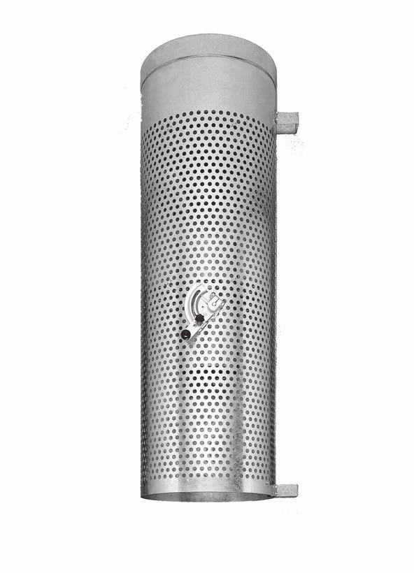
2 Construction design and function Preliminary remarks Displacement air outlets enable to extract pollutants from production and work areas efficiently and without substantial mixing with indoor air. Depending on both the type of pollutants and the specific internal heat load, the displacement outlets are placed either above the occupied zone or on the floor. Thus low pollutant and heat load factors can be achieved 1). The circular displacement outlet with adjustable damper by KRANTZ KOMPONENTEN is eminently suited for installation above the occupied zone or on the floor. The air discharge direction can be adjusted from a slight incline upwards to vertically downwards; this enables to get a constantly ideal indoor air flow despite varying internal heat gains. If the outlet is placed at about 3 m height, a pollutant load factor of 55 to 57% can be achieved (against 90 to 100% with turbulent mixing ventilation), depending on the outlet setting. If it is placed on the floor, the pollutant load factor is as low as about 0%. Such values can be reached only with displacement outlets whose discharge direction can be adjusted, as is the case with the circular displacement outlet with adjustable damper described here. The heat load factor is low too: about 65% with the outlet at 3 m height, and about 5% with the outlet on the floor. KRANTZ KOMPONENTEN supplies different systems for adjusting the outlet damper: three manual options, an electric servomotor as well as a thermal control unit which controls the damper, and thus the air discharge direction, in response to the difference in temperature between the supply and indoor air without auxiliary energy. Construction design and function The main components of the circular displacement outlet with adjustable damper are the perforated cylinder 1 with connection spigot and plain bottom 3, the orifice rings, and the air deflection tube 5 with built-in adjustable damper 6. The outlet is made of galvanized sheet metal. Owing to its particular design the perforated cylinder generates a low-turbulence displacement flow around the air outlet. ø D A b 10 1 Fig. : Circular displacement outlet with adjustable damper left: adjustment with control lever right: adjustment with Bowden cable 5 6 ø DN 3 7a T ø Key 1 Perforated cylinder Connection spigot 3 Bottom Orifice ring 5 Air deflection tube 6 Adjustable damper 7a Fastener for wall mounting (option) 7b Two opposite -fasteners (option) Size Volume flow rate for placement at 3 m height on the floor Dimensions Ø V. A min V. A max V. A min V. A max Ø D A T Weight DN l/s m 3 /h l/s m 3 /h l/s m 3 /h l/s m 3 /h mm mm mm mm kg DS 059 E p Fig. 1: Sizes and dimensions 1) Pollutant load factor = ratio of pollutant concentration at the workplace to pollutant concentration in the return air, in %. Heat load factor = ratio of heat load at the workplace to total heat gains, in %.
3 Placement For even supply air flow and thus higher thermal comfort, the outlet type for floor placement has finer perforations and works with reduced air flow rate (70% against type for placement at 3 m height). The air deflection tube and the adjustable damper enable the continuous alteration of the air discharge direction from a slight incline upwards (cooling mode) to vertically downwards (heating mode). The damper can be adjusted manually, by an electric servomotor, or by a thermal control unit. For manual adjustment there are 3 options available: a Bowden cable, a chain pull, or a control lever which will be positioned on the outlet surface. The minimum spacing between the air outlet and the next workplace can be read off Graph 5 (page 7). 1.5 DN Air outlet placement The air outlet can be placed either above the occupied zone or on the floor (Fig. 3), anywhere in the room or in front of a wall or pillar. a) Placement above the occupied zone In spaces with low specific heat loads or where heavy pollutants are released, the air outlets are best placed above the occupied zone. The air is supplied from above (Fig. 3, top). The recommended discharge height is 3 m (underside of air outlet). The removal of heavy pollutants is facilitated by the extraction of about 50% of the return air at floor level. The purpose of the built-in damper is to adapt the air discharge direction to the cooling or heating mode. In work areas where heat loads vary heavily, the best way of adjusting the damper is using an electric servomotor or a thermal control unit. In other cases manual adjustment will be adequate, using a Bowden cable or a chain pull which will be operated from the occupied zone. b) Placement on the floor This arrangement is best suited either for removing high specific heat loads (q. > 10 W/m ) or where light pollutants are released. The direction of the supply air jets supports the buoyancy forces and helps convey the light pollutants away to the return air ducts. The air outlet can be placed either directly on the floor or on a customer supplied base having a maximum height of 0.5 m (Fig. 3, bottom). For this arrangement the outlet has a finely perforated cylinder and the maximum air flow rate is 30% less than for placement at 3 m height (see table in Fig. 1). The air discharge direction is usually adjusted manually, using a control lever positioned on the outlet surface. Yet if self-adjustment is preferred, it is advisable to use a thermal control unit. Heavy pollutants: about 50% of the return air is extracted at floor level approx. 3 m ight pollutants DS 059 E p m Fig. 3: Examples of placement top: above the occupied zone bottom: on the floor Q 3
. This lifts the complete air stream and increases the height of the supply air layer.")
, the discharge flow is affected by more or less strong buoyancy")
4 Air jet dispersion Cooling mode: With the adjustable damper open, a partial volume of air gets through the deflection tube to the outlet bottom where it is deflected before being discharged slightly upwards (Fig., Cooling). This lifts the complete air stream and increases the height of the supply air layer. Whether the outlet is placed above the occupied zone or on the floor, an even low-turbulence displacement flow builds up around the air outlet, with a large penetration depth into the occupied zone. Heating mode: In low-turbulence displacement ventilation, if the supply air temperature is above the room temperature (when heating), the discharge flow is affected by more or less strong buoyancy forces; as the supply air starts moving upwards too early it cannot achieve the required penetration depth. The case is different with the KRANTZ KOMPONENTEN circular displacement outlet! Its built-in air deflection device enables to offset the buoyancy forces: with the damper closed (Fig., Heating), the outlet generates a radial downflow which counters the buoyancy forces of the warm supply air that can thus penetrate deep into the room. Circular displacement outlet VA-ZD Air jet dispersion Cooling: damper open Heating: damper closed approx. 3 m approx. 3 m Cooling: damper open Heating: damper closed 1) Fig. : Air jet dispersion top: with outlet above the occupied zone bottom: with outlet on the floor 1) See Selection and layout on page 5 Fig. 5: Air jet dispersion made visible by smoke tracer top: cooling mode bottom: heating mode Air flow geared to requirements The above description of air jet dispersion when cooling and heating relates to damper settings open and closed respectively. In practical operation, however, the supply air is usually introduced into the space at various intermediate settings of the damper, depending on the prevailing DS 059 E p
5 Selection and layout cooling load. The damper being steplessly adjustable, it allows to gear the direction of the supply air jets to the cooling or heating requirements and thus to achieve an efficient and uniform air flow within the occupied zone. This enhances the thermal comfort of the occupants and in most cases obviates the need for an extra heating device in winter. As the circular displacement outlet is able to discharge the whole supply air vertically downwards, it is eminently suited for accelerating the heating up of the space concerned, e.g. after a prolonged interruption in operation. This ability can also be used to flush the occupied zone with more fresh air prior to start of work or during breaks. For placement at about 3 m above the occupied zone we recommend a maximum temperature difference of ±10 K between supply air and indoor air. Cooling DS 059 E p Selection and layout The circular displacement outlet with adjustable damper can be used in all fields of trade and industry. Whether it will be placed above the occupied zone or on the floor depends on both the type of pollutants to be extracted and the amount of specific heat gains. Industrial applications require specific supply air flow rates of to 8 l/(s m ) [15 to 100 m 3 /(h m )] or more, depending on the production process. This broad range can be achieved by selecting the appropriate number and size of air outlets with the related air flow rates as well as the most suitable placement (anywhere in the space or in front of a wall or pillar). We recommend to select, as far as possible, an air flow rate within the upper range (see graphs on pages 6 and 7 as well as table in Figure 1) if a great difference in temperature between supply air and indoor air 1) is required for heating the space and a large supply air penetration depth is required. It is most important to know the coverage of the supply air jets to be able to make a proper layout. For outlet placement above the occupied zone a distinction is made between the primary penetration depth and the maximum supply air penetration depth (Fig. 6). In the cooling mode the primary penetration depth denotes the furthest point from the air outlet at which the entire supply air has entered the occupied zone. In the heating mode it denotes the point at which the first portions of supply air begin to move upwards. The maximum supply air penetration depth is shown in the graphs on page 6. The primary penetration depth is about one third shorter. 1) We recommend measuring the indoor air temperature in the occupied zone, for control purposes Primary penetration depth or Maximum supply air penetration depth max = 1.5 x or Primary penetration depth or Maximum supply air penetration depth max = 1.5 x or Fig. 6: Primary penetration depth and maximum supply air penetration depth for outlet placed above the occupied zone Heating In case of outlet placement on the floor the maximum supply air penetration depth when cooling depends only on the number and intensity of heat sources. For the cooling mode we recommend a minimum supply air temperature of 18 C and for the heating mode a maximum temperature difference of 10 K between supply air and indoor air. When heating, the horizontal penetration depth of the supply air depends not only on its volume flow rate and temperature, but also on the prevailing indoor conditions. The optimum penetration depth can be set by adjusting the damper 6. The outlet layout will be made using the graphs that follow. 5
6 ayout sheet for placement at about 3 m above the occupied zone Air outlet free-hanging in room Air outlet in front of a wall Air outlet in front of a pillar Two air outlets on either side of a pillar V A in m 3 /h l/s = Max. supply air penetration depth when cooling max in m Sound power level WA in db(a) ref W Total pressure loss p t in Pa Max. supply air penetration depth when heating 1 max in m Outlet size Min. volume flow rate for placement at 3 m height V. A min on the floor V. A min Ø DN l/s m 3 /h l/s m 3 /h Temperature difference supply air indoor air when heating in K l/s m 3 /h Air outlet volume flow rate V A ayout example: Placement at 3 m above the occupied zone, in front of a pillar 1 Air outlet volume flow rate V. A = 150 l/s [500 m3 /h] Required supply air penetration depth = 11 m 3 Temperature difference supply air indoor air DJ = + 5 K when heating Maximum allowable sound power level WA = 65 db(a) ref W From Graph 1: 5 Outlet size = 6 Max. supply air penetration depth max = 1 m (when cooling) 7 WA = 63 db(a) ref W 8 Dp t = 110 Pa DS 059 E p From Graph : 9 Max. supply air penetration depth max 1.5 m (when heating) 6
7 ayout sheet for placement on the floor Air outlet free-standing in room Air outlet in front of a wall Air outlet in front of a pillar Two air outlets on either side of a pillar 1 = 0.65 Note: The maximum supply air penetration depth when cooling largely depends only on the number and intensity of heat sources. Under normal conditions the maximum supply air penetration depth is max = 10 m with size and max = 5 m with size. These figures apply for the respective maximum volume flow rates. With specific heat loads over 10 W/m the above maximum supply air penetration depths must be reduced by 30%. V A in m 3 /h l/s Sound power level WA in db(a) ref W Total pressure loss p t in Pa Max. supply air penetration depth when heating 1 max in m Recommended min. spacing from workplace tmin in m 5 DS 059 E p Temperature difference supply air indoor air when heating in K l/s m 3 /h Air outlet volume flow rate V A l/s ayout example: Placement on the floor, in front of a wall 1 Air outlet volume flow rate V. A = 975 l/s [3500 m 3 /h] Required supply air penetration depth = 9 m 3 Temperature difference supply air indoor air DJ = + 5 K when heating Maximum allowable sound power level WA = 65 db(a) ref W From Graph 3: 5 Outlet size = 6 WA = 6 db(a) ref W 7 Dp t = 90 Pa From Graph : 8 Max. supply air penetration depth max 1 m (when heating) From Graph 5: 9 t min =.7 m m 3 /h 7000 Air outlet volume flow rate V A 7
8 Altering the air discharge direction Altering the air discharge direction The air discharge direction will be altered by the adjustment of the built-in damper either manually or via an electric servomotor or a thermal control unit ) ) Manual adjustment a) with a Bowden cable which is linked to a control lever fixed to a support for wall or pillar mounting and enables the stepless setting of different air discharge directions (Fig. 8). 1) 1) b) with a chain pull which hangs down through the outlet bottom and enables to open or close the damper. In the cooling mode the damper is open, with the chain being uplifted by about 150 mm by a tension spring. To close the damper when heating, the chain must be pulled down. To stop the chain and thus set the damper position, chain links must be jammed in the keyhole aperture in the outlet bottom. Visible chain length: cooling to heating = 1000 to 1150 mm H 3 m H 1.5 m Bowden cable A H 3 m Visible chain length heating 1150mm 1.5 m cooling 1000mm =150mm Chain pull Floor Floor Fig. 7: Keyhole aperture in outlet bottom for passage and stoppage of chain pull Adjustment with Bowden cable or chain pull is to be preferred for outlet placement in front of a wall or pillar (Fig. 8). View A: Support with control lever Control lever to the left: The supply air is discharged at an upward incline: cooling mode Control lever to the right: The supply air is discharged steeply downwards: heating mode Intermediate settings of the control lever enable to adjust the direction of the supply air jets to the prevailing thermal loads. c) with a control lever positioned on the perforated cylinder. The control lever setting indicates the air discharge direction (Fig. 9). This adjustment system is often used for outlets placed on the floor. Yet it can also be used for outlets placed above the occupied zone if damper adjustment is required only seldom. DS 059 E p ) < Heating (damper closed) ) <.. Cooling (damper open) Fig. 8: Manual alteration of discharge direction via Bowden cable, top left and bottom chain pull, top right 8
9 Altering the air discharge direction In the predefined basic setting for the thermal control unit, the damper control range is 90 to 35 (= damper angle a). This basic setting is normally sufficient for room temperatures t R of 1 to 8 C. The air discharge direction varies according to the damper angle, e.g. from a = 90 slight upward incline to a = 35 steep downflow. ) ) Servomotor DS 059 E p ) Control lever Fig. 9: Alteration of discharge direction left: manually, via control lever right: automatically, via electric servomotor Adjustment by electric servomotor The servomotor is lodged inside the outlet housing, against the air deflection tube. Its power cord runs through the perforated cylinder. This type of adjustment is best suited if the client requires the automatic alteration of the discharge direction in relation to the temperature difference between the supply and indoor air, or a centrally controlled heating-up process, or forced controls, or in case several outlets are to be adjusted simultaneously. Adjustment by thermal control unit With the thermal control unit the adjustable damper, and with it the air discharge direction, is self-adjusted without auxiliary energy in response to the temperature difference between the supply and indoor air. This unit controls the heating and cooling modes most efficiently. Design and mode of operation (Fig. 10) The main component of the thermal control unit is a piston mechanism 8 with expandable material which is positioned in the intake spigot of the air outlet; it is fitted with a temperature sensor in the supply air flow 8a and one for the indoor air 8b. The temperature difference between the supply and indoor air produces a piston stroke which is transmitted to the damper 6 via a rod assembly 9. The damper angle a controls the air discharge direction. If a is large, the supply air is discharged at a slight upward incline; small, the supply air is discharged steeply downwards. 1) How to change the basic setting In some few applications it may be useful to change the direction of the supply air jets beyond the basic setting. If circular displacement outlets are used, for instance, in industrial halls with all-year high room temperatures, a supply air stream being directed more downwards is likely to increase the fresh air effect. On the other hand, in the cooling mode, in spaces with all-year low room temperatures, the thermal comfort of the individual occupants can be enhanced by directing the supply air stream more upwards. It is also possible to select different air discharge directions for individual outlets depending on the areas where they are located, e.g. flatter above occupied zones and steeper downwards above gangways. For such cases the setting for the thermal control unit can be altered from the outside at the damper angle setting plate 10. The damper angle setting can be altered by ±0. Example 1: All-year room temperature t R ³ 8 C; if there is a need for more air movement within the space, the air discharge must occur steeper downwards for increased fresh air effect adjustment towards the red mark. 8b a 0 red blue 0 Key 6 Adjustable damper 8 Piston mechanism 8a Temperature sensor for supply air 8b Temperature sensor for indoor air 9 Rod assembly 10 Damper angle setting plate red: increased air movement blue: reduced air movement Fig. 10: Circular displacement outlet with built-in thermal control unit in basic setting (position 0 ) 1) < Heating (damper closed) ) <.. Cooling (damper open) 9
10 Volume flow rate setting and outlet fastening Example : All-year room temperature t R < 0 C; if there is a need for less air movement within the space, the air discharge must occur at a slightly greater upward incline and the total supply air stream will get flatter adjustment towards the blue mark. The following graph (Fig. 11) shows the damper angle for different settings, in response to the temperature difference between the supply and indoor air, and the resulting air discharge directions. Due to hysteresis the actual damper angle may differ by about 5 from the theoretical value. This increases the sound power level by approx. db(a) ref W. max. 70 H H1 11 ø D A 7a H3 90 H H + 0 (blue mark) Damper angle in degrees (red mark) Air discharge directions 1 ø DN Temperature difference = Z R in K Fig. 11: Damper angle a in response to the temperature difference between the supply and indoor air, and resulting air discharge directions Volume flow rate setting In general, the volume flow rate setting for several VA-ZD outlets fed by the same ductwork occurs via volume flow rate throttle devices to be provided by the client. As a rule, these throttle devices are positioned immediately upstream of the air outlets. For such cases KRANTZ KOMPONENTEN supplies, on request, specially designed volume flow dampers to be fitted onto the VA-ZD outlets, on the air intake side. Their advantages are: no impairment of air flow pattern, no further pressure drop and no increase in sound power level when the damper is open. When the volume flow damper is closed, the pressure drop can be.5 times as high as it is in the open position. Key 1 Perforated cylinder 7a Fastener Connection spigot 11 Adjusting device for volume flow damper Size ø D A mm H mm H 1 mm H mm H 3 mm H mm Fig. 1: Volume flow damper fitted onto a VA-ZD outlet (on air intake side) Air outlet fastening a) Placement above the occupied zone In this placement option the air outlet is frequently mounted on a wall or pillar, using two fasteners 7a with boreholes ø 11 mm positioned at the top and bottom of the outlet housing. For fastening, the client will insert screws of type M10, for instance, into brickwork anchors having the same size. If the outlet is freely suspended, fastening can be done, for example, by riveting or bolting to the round air duct. Further, suspension from the ceiling can be done with two opposite -fasteners 7b positioned on the air intake side and designed for fastening threaded rods or similar fixtures. DS 059 E p
 or it will be fastened to the floor using brackets to be provided by the client.")

11 b) Placement on the floor In this placement option the air outlet is set up either directly on the floor or on a base having a maximum height of 0.5 m. It will be fixed using the available fasteners 7a (if standing against a wall or pillar) or it will be fastened to the floor using brackets to be provided by the client. Circular displacement outlet VA-ZD Features Cost-effective control With the exception of forced control 1), the thermal control unit offers the same control options as, for instance, an electric temperature difference control device. It also enables various settings for different room control zones. This control system obviates the need for electric servomotors inside the air outlets, wiring, controllers, and switch cabinet with power supply unit; this means no additional energy costs. Controlling with thermal control units is much cheaper than with servomotors, especially in the case of reconfiguration of the space and/or rearrangement of the outlets concerned. DS 059 E p Features ow-turbulence radial displacement flow High fresh air quality in the occupied zone Placement above the occupied zone or, with finely perforated cylinder, on the floor Stepless alteration of air discharge direction thanks to built-in adjustable damper, thus well suited for cooling and heating Adjustment options: manual, by electric servomotor, or by thermal control unit Rapid decrease in radial jet velocity Primary penetration depth of supply air jets: up to approx. 1 m; maximum supply air penetration depth: approx. 0 m Max. temperature difference supply air indoor air with placement above the occupied zone: DJ = ±10 K when heating or cooling with placement on the floor: DJ = +10 K when heating, minimum supply air temperature: 18 C when cooling Volume flow rate range: 19 to 800 l/s [700 to m 3 /h] 6 sizes available: to Option: volume flow damper for even air supply to several displacement outlets connected to the same ductwork Made of galvanized sheet metal For connection to ducts to DIN 15 Robust construction with only few adjustable parts Fig. 13: Circular displacement outlets in car manufacturing halls 1) e.g. to accelerate heating up 11
12 Type code and tender text Type code VA-ZD DN Displacement outlet Mounting Size Adjustment Mounting A = 3 m above the occupied zone B = placement on floor Damper Surface finish Size 50 = 50 = 315 = 560 = 355 = 630 = Accessories Adjustment E = Belimo servomotor, 0 10 V modulation, rotation drive type MA-SR B = Bowden cable K = chain pull S = control lever T = thermal control unit Damper O = no volume flow damper V = with volume flow damper Surface finish galv = galvanized 9006 = face painted to RA 9006, semi-matt. = face painted to RA. Accessories O = none H = fasteners for wall mounting W = -fasteners for suspension Tender text... units Circular displacement outlet generating a low-turbulence supply air flow and minimal mixing of supply air with indoor air for optimum displacement of airborne particles and pollutants from the occupied zone, consisting of: a perforated cylinder with connection spigot and plain bottom, and a built-in air guiding device with orifice rings, an air deflection tube and an adjustable damper for adapting the air discharge direction to varying internal thermal loads when heating and cooling. Adjustment of air discharge direction either manually with Bowden cable 1), chain pull 1) or control lever on perforated cylinder or by electric servomotor or by built-in thermal control unit for automatic damper adjustment in response to the difference in temperature between the supply and indoor air, using a piston mechanism with expandable material. The piston stroke is transmitted to the adjustable damper by a rod assembly. The basic setting of the damper angle can be altered by the client at the damper angle setting plate. The outlet will be either suspended above the occupied zone or placed on the floor (cylinder with finer perforations). It will be optionally fitted with fasteners for wall or pillar mounting or with two opposite -fasteners (on the air intake side) for suspension with threaded rods or similar fixtures. Option: volume flow damper with perforated blade, specially designed for the circular displacement outlet, for even air supply to several outlets connected to the same ductwork, with round casing and adapter sleeve for fitting onto the outlet housing (air intake side) and with external adjusting device. Material: Air outlet made of galv. sheet metal ), visible outlet parts optionally painted to RA... Make: Type: Subject to technical alterations. KRANTZ KOMPONENTEN VA-ZD DN 1) For placement at 3 m above the occupied zone; any other discharge height is to be specified in the related enquiry and/or order ) Stainless steel upon request DS 059 E p Krantz GmbH Uersfeld, 507 Aachen, Germany Phone: Fax: info@krantz.de
for Asia / Pacific Radial outlet RA-N3... DS 4134 AUS /
 for Asia / Pacific Radial outlet RA-N... DS AUS./ Radial outlet RA-N Preliary remarks KRANTZ KOMPONENTEN radial outlets of type RA-N have fixed radial vanes. They generate high-quality, diffuse supply
Krantz Components. Multifunction sail AVACS. Cooling and heating systems
 Multifunction sail AVACS Cooling and heating systems DS 4170 E 01.2014 Preliminary remarks and construction design Preliminary remarks The multifunction sail AVACS is designed for use with plane metal
Round duct nozzle jet diffuser Model DSA-RR
 Round duct nozzle jet diffuser Model DSA-RR Ferdinand Schad KG Steigstraße 25-27 D-78600 Kolbingen Telephone +49 (0) 74 63-980 - 0 Fax +49 (0) 74 63-980 - 200 info@schako.de www.schako.de Contents Description...3
Krantz Components. Multifunction Sail AVACS. Cooling and Heating Systems
 Multifunction Sail AVACS Cooling and Heating Systems 2 AVACS Air Ventilation And Cooling System 3 System design Air diffuser box Air connection Sound absorbers (optional) Cooling element with heat conducting
Adjustable swirl diffuser ODZA TECHNICAL DATA
 Adjustable swirl diffuser ODZA TECHNICAL DATA 2 Adjustable swirl diffuser ODZA Adjustable ceiling swirl diffuser ODZA is intended for commercial and industrial buildings with a large room volume and high
Krantz Components. Displacement ventilation for indoor firing ranges. Air distribution systems
 Displacement ventilation for indoor firing ranges Air distribution systems Low-turbulence displacement ventilation protects the breathing zone of the shooter 2 When shooting with firearms, pollutants in
TRAVSMART permanent single-cable horizontal lifeline system
 The Travsmart single-line system provides a smooth travel. It allows the traveler to move freely over the intermediate anchors, minimizing wear and eliminating user assistance. The user s hands remain
Inflatable Packer Single & Double. Single & Double Packer Dimension. Wireline Packer. Water Testing Packer (WTP) Packer
 Packer") Inflatable Packer Single & Double Single & Double Packer Dimension Wireline Packer Water Testing Packer (WTP) Packer Packer Working Pressure & Depth Chart Packer Water Hand Pump Packer Air Driven Pump
Inflatable Packer Single & Double Single & Double Packer Dimension Wireline Packer Water Testing Packer (WTP) Packer Packer Working Pressure & Depth Chart Packer Water Hand Pump Packer Air Driven Pump
C O L M A N. Air Distribution SWIRL DIFFUSERS DRS SERIES DRS SERIES
 C O L M N ir Distribution E N G I N E E R E D I R P R O D U C T S SWIRL DIFFUSERS DRS SERIES DRS SERIES D SERIES SWIRL DIFFUSERS pplication The DRS, DQS, DCS and DSS series of fixed circular swirl diffusers
Vibration isolation system 1VIS10W. User manual
 Vibration isolation system 1VIS10W User manual Standa 2014 Table of contents 1. General information 3 1.1. Introduction 3 1.1.1. Safety 5 1.2. Location of the table 5 1.3. Air supply requirements 5 2.
Chilled beam iq Star WEGA II
 Chilled beam iq Star WEGA II Key features Ventilation Water Heating and cooling Adjustable induction Flow Pattern Control In option: Demand Controlled Ventilation, Pressure independent, Electrical heating,
Automatic extractor outlet
 L-07-2-01e Automatic extractor outlet Type HFA Contents Application Realisation Operation Safety instructions Contents Application Realisation Operation Safety instructions 2 Connection diagram Dimensions
Rp [ ] Sv min. [ ] C215QP-B 15 1/ C215QP-D 15 1/ C220QP-F 20 3/ [ ]
![Rp [ ] Sv min. [ ] C215QP-B 15 1/ C215QP-D 15 1/ C220QP-F 20 3/ [ ]](/thumbs/75/72185867.jpg "Rp [ ] Sv min. [ ] C215QP-B 15 1/ C215QP-D 15 1/ C220QP-F 20 3/ [ ]") Technical data sheet C2..QP-.. For closed cold and warm water systems For modulating control of airhandling and heating systems on the water side Snap-assembly of the actuator overview DN [ ] Vnom [ l/h]
Technical data sheet C2..QP-.. For closed cold and warm water systems For modulating control of airhandling and heating systems on the water side Snap-assembly of the actuator overview DN [ ] Vnom [ l/h]
Armatures for analytical probes
 Armatures for analytical probes For many different types of installations and applications Large range of probe holders General purpose, water treatment, food & beverage, pharmaceutical applications Type
Draw-wire system SZG165
 Draw-wire system SZG165 www.wachendorff-automation.com Wachendorff Automation... systems and encoders Complete systems Industrial rugged encoders to suit your application Standard range and customer versions
Extension Platform. Base Platform. Crossover. Exit railing. Exit Railing
 Base Platform Galvanized With metal grate and two brackets Railing on the long side and a face side Extension Platform Galvanized With metal grate and one bracket Railing on the long side with rail connection
CALEFFI. Ball zone valves. series /03 GB
 all zone valves series cert. n ISO / Function Zone valves are used to automatically shut-off the flow of carrier fluid distributed to a system. Specifically: -In central heating systems, they support the
DICTATOR "DIREKT" Gate Closer
 DICTATOR "DIREKT" Gate Closer For Access Gates in Boundary Fences The DICTATOR gate closer DIREKT is the economic solution for the controlled closing of outside gates, such as admission gates to kinder
BENEFITS SAMPLERS FOR SUSPENDED SEDIMENT P Watertrap sampler. The winch of the Watertrap is fixed to the railing of a bridge.
 Sediment is transported by running water. The lighter particles are transported by the water in a suspended state. For the sampling of this suspended sediment for calculation of the overall quantity of
Gas Pressure Regulator HON 200
 Product information serving the gas industry worldwide Applications, characteristics, technical data Application Gas supply to municipal, industrial and individual consumers Regulator for low-load rails
Pneumatic Grippers Swivel Modules
 Pneumatic Grippers Swivel Modules Pneumatic Grippers Swivel Modules ROTARY GRIPPERS MODULES Series Size Page GSM 748 Parallel Grippers GSM-P 750 GSM-P 32 754 GSM-P 40 760 GSM-P 50 766 GSM-P 64 772 Centric
DICTATOR "DIREKT" Gate Closer
 DICTATOR "DIREKT" Gate Closer For Access Gates in Boundary Fences The DICTATOR gate closer DIREKT is the economic solution for the reliable and controlled closing of outside gates, such as admission gates
Supply air diffuser ROFB, RPFB
 Supply air diffuser ROFB, RPFB ROFB and RPFB are supply air diffusers with an integrated plenum box for freely suspended installation in a ceiling. The diffuser ROFB comes with an unperforated and RPFB
Smooth Vent Valve. Series XVD XL XL Q D- XVD XGT CYV
 Smooth Vent Valve Series Valve / needle valve integrated construction requires only 1/4 the piping space of previous models. Particulates significantly reduced through the use of a metal diaphragm in the
INSTRUCTION MANUAL. January 23, 2003, Revision 0
 INSTRUCTION MANUAL Model 810A In-Vitro Test Apparatus for 310B Muscle Lever January 23, 2003, Revision 0 Copyright 2003 Aurora Scientific Inc. Aurora Scientific Inc. 360 Industrial Parkway S., Unit 4 Aurora,
PFH. Application example. Pneumatic 2-Finger Parallel Gripper Long-stroke Gripper. Weight 2.65 kg 12.6 kg. Gripping force 630 N 2950 N
 PFH www.comoso.com Sizes 30 50 Weight 2.65 kg 12.6 kg Gripping force 630 N 2950 N Stroke per finger 30 mm 100 mm Workpiece weight 3.15 kg 13 kg Application example Assembly unit for intermediate sleeves
TECHNICAL DESCRIPTION
 TECHNICAL DESCRIPTION Exhaust Hose Reel ser. 865, electric motor driven No. 981118101 Description Limit switches, for hose coiling and uncoiling integrated in drive unit. Motor turns drum via a planetary
Micro grippers HGPM/HGWM
 HGPM/HGWM Miniaturised and optimised for assembly tasks Versatile 2004/10 Subject to change Products 2004/2005 1 / 1 HGPM/HGWM Key features HGWM HGPM 1 2 3 4 1 2 3 4 System product for handling and assembly
Components for air preparation and pressure adjustment. OUT port position ( ) connected Rear side. of IN port. Air tank. directly.
 connected Rear side. of IN port. Air tank. directly.") Components preparation and pressure adjustment ABP Overview ABP is a component that enables boosting by s only up to twice primary pressure (.0MPa max.) in combination with using air tank but not using
Components preparation and pressure adjustment ABP Overview ABP is a component that enables boosting by s only up to twice primary pressure (.0MPa max.) in combination with using air tank but not using
TECHNICAL DATA. TRIMPAC Model B-5 & B-5B
 September 16, 2013 Trimpac 250a 1. DESCRIPTION DEsCRIPTIoN is a factory assembled trim package for a ed an electric/pneumatic release module in a metal enclosure. The standard trim normally required on
Poollift Delphin. Version: February, 2015 MANUAL AND OPERATING INSTRUCTIONS
 Poollift Delphin Version: February, 2015 MANUAL AND OPERATING INSTRUCTIONS Content 1. Introduction... 3 2. Technical Specifications... 3 Used materials... 3 3. Installation Instructions... 4 Fastening
Overview of types. T5-R B2/R B2 en v Subject to changes 1 / 4. k vs (Sequence 2)
") Technical data sheet R3015-..-..-B2 / R3020-..-..-B2 Characterised control valves, 6-way, with internal threads Two sequences (cooling/heating) With a rotary actuator 90 Water-side switching or modulating
Technical data sheet R3015-..-..-B2 / R3020-..-..-B2 Characterised control valves, 6-way, with internal threads Two sequences (cooling/heating) With a rotary actuator 90 Water-side switching or modulating
Type 4708 Supply Pressure Regulator
 Type 478 Pressure Regulator Application pressure regulators used to provide pneumatic measuring and control equipment with a constant air supply Set point ranges. to. bar ( to 4 psi). to bar (8 to 9 psi)
SPG. Application example. Pneumatic 2-Finger Parallel Gripper Heavy-load Gripper. Weight 35 kg. Stroke per finger 100 mm.
 SPG Size 100 Weight 35 kg 10,000 N Stroke per finger 100 mm Workpiece weight 50 kg Application example Gripper unit for heavy V8 engine blocks. SPG 100 2-Finger Heavy-load Gripper 446 www.schunk.com SPG
DPZ-plus. Application example. Pneumatic 3-Finger Centric Grippers Sealed Grippers. Gripping force 520 N N. Sizes
 DPZ-plus Sizes 64.. 200 Weight 0.62 kg.. 20.1 kg Gripping force 520 N.. 16800 N Stroke per finger 3 mm.. 25 mm Workpiece weight 2.6 kg.. 60.0 kg Application example Insertion tool for assembling small
GAS PRESSURE CONTROL UNIT TYPE 132
 GAS PRESSURE CONTROL UNIT TYPE 132 OUR DIVERSITY IS YOUR PROFIT. Gas Pressure Regulator Type 132 Scope of Application Scope of type 132 gas pressure regulator is to maintain the output pressure at a constant
TECHNICAL DATA. Trimpac 251a. Spetember 16, 2013
 Spetember 16, 2013 Trimpac 251a 1. DEsCrIpTION DESCRIPTION TRIMPAC Model B-6 and B-6B is a factory assembled trim package for a double interlocked preaction system with an electric/pneu-lectric release
Air Operated Hydraulic Pumping Systems to 50,000 psi
 High Pressure Equipment Air Operated Hydraulic Pumping Systems to 50,000 psi PS-10: 10,000 psi PS-20: 20,000 psi PS-30: 30,000 psi PS-40: 40,000 psi PS-50: 50,000 psi PS-90: 90,000 psi High Pressure air
BIMBAR INFLATABLE PACKERS AND ACCESSORIES
 BIMBAR INFLATABLE PACKERS AND ACCESSORIES Geopro supplies a complete range of inflatable packers in nine different diameters from 28 up to 170mm. All our packers made of BIMBAR rubber technology are reinforced
Supplementary instructions. Rod and cable components. for VEGAFLEX series 80. Document ID: 44968
 Supplementary instructions Rod and cable components for VEGAFEX series 80 Document ID: 44968 Contents Contents 1 Product description 1.1 Extensions... 3 2 Mounting 2.1 General instructions... 6 2.2 Rod
Pipe Thread Connection 1/2 inch NPT. Friction Loss Refer to Figure 3
 Worldwide Contacts www.tyco-fire.com Model B-1 Pipe Line Strainer General Description The Model B-1 Pipe Line Strainers (Ref. Figures 1 and 2) are designed for installation in the water supply connection
GLAUNACH THE SILENCER HANDBOOK INSTALLATION GLAUNACH GMBH ALL RIGHTS RESERVED -
 GLAUNACH THE SILENCER HANDBOOK INSTALLATION GLAUNACH GMBH 2010 - ALL RIGHTS RESERVED - Part VII page 2 of 8 1. CHOOSING THE INSTALLATION LOCATION When selecting a suitable site for the installation of
pneumatic power clamps
 pneumatic power clamps Features Király Trading KFT H-1151 Budapest Mogyoród útja 12-14 E-mail:_agi@kiralytrading.hu Your requirements Power element of machines, tools and devices for the following applications:
Smooth Vent Valve XVD. Series
 Smooth Vent Valve Series Valve / needle valve integrated construction requires only 1/4 the piping space of previous models. Particulates significantly reduced through the use of a metal diaphragm in the
TECHNICAL DATA. Trimpac 244a. September 16, 2013
 September 16, 2013 Trimpac 244a 1. DEsCrIpTION DESCRIPTION TRIMPAC Model B-1 and B-1B is a factory-assembled trim package with an electric release module in a metal enclosure. The standard trim normally
Pilot HON 625. Entwurf. Product information. serving the gas industry worldwide
 Pilot HON 62 Entwurf Product information serving the gas industry worldwide Pilot HON 62 Application, characteristics Application Pilot for the gas pressure regulator HON 02 Pilot for outlet pressure control
PFH. Application example. Pneumatic 2-Finger Parallel Grippers Long-stroke Grippers. Sizes Gripping force 510 N N
 PFH Sizes 30.. 50 Weight 2.65 kg.. 9.7 kg Gripping force 510 N.. 2650 N Stroke per finger 30 mm.. 50 mm Workpiece weight 2.55 kg.. 11.5 kg Application example Assembly unit for intermediate sleeves in
Pneumatic spool valve islands
 Pneumatic spool valve islands P7.GB.R MEGA SPOOL VALVE ISLANDS MEGA pneumatic spool valve islands offer maximum performance along with flexibility, easy installation and simple operation. Due to their
Mounting and Operating Instructions EB 3007 EN. Self-operated Pressure Regulators. Differential Pressure Regulators (opening) Type Type 42-25
 Type Type 42-25") Self-operated Pressure Regulators Differential Pressure Regulators (opening) Type 42-20 Type 42-25 Type 42-20 Differential Pressure Regulator Type 42-25 Differential Pressure Regulator Mounting and Operating
Self-operated Pressure Regulators Differential Pressure Regulators (opening) Type 42-20 Type 42-25 Type 42-20 Differential Pressure Regulator Type 42-25 Differential Pressure Regulator Mounting and Operating
PHOENIX, ARIZONA USA
 NEW PRODUCTS MODEL: US-AASS-80 DESCRIPTION: Cantilever Arm 80 MEETS OSHA & ANSI Z359.14 CLASS B 1-800-850-5914 PHOENIX, ARIZONA USA WWW.ULTRASAFEUSA.COM CANTILEVER ARM The Ultra-Safe cantilever arm has
Smooth Vent Valve. XVD Series
 Smooth Vent Valve Series Valve / needle valve integrated construction requires only 1/4 the piping space of previous models. Particulates significantly reduced through the use of a metal diaphragm in the
CEILING DIFFUSERS technical CONTROL THE AIR YOU BREATHE. types -CD, CAB. Europair Africa a division of Performancair Products Africa (Pty) Ltd
 Ltd") CEILING DIFFUSERS technical types -CD, CAB Europair Africa a division of Performancair Products Africa (Pty) Ltd tel +27 11 974 2425 fax +27 11 974 7251 web www.europair-africa.com email: info@europair-africa.com
CEILING DIFFUSERS technical types -CD, CAB Europair Africa a division of Performancair Products Africa (Pty) Ltd tel +27 11 974 2425 fax +27 11 974 7251 web www.europair-africa.com email: info@europair-africa.com
High-performance submersible pressure transmitter For level measurement Model LH-10
 Electronic pressure measurement High-performance submersible pressure transmitter For level measurement Model LH-10 WIKA data sheet PE 81.09 Applications Level measurement in rivers and lakes Deep well
INSTRUCTION MANUAL Pressure Relief Device LPT
 INSTRUCTION MANUAL Pressure Relief Device LPT 5COV475800 LPT REV00 CONTENT: 1 SAFETY 1.1 Safety instructions 2 1.2 Specified applications 2 1.3 Safety notes on the equipment operation 2 2 PRESSURE RELIEF
Easy to operate even for biginners. Set up the number of test. Possible to select from 1 to times
 With a force gauge and attachments, compression/tensile/peeling tests are possible up to 1000N/2500N. It provides consistent testing speed and direction, offering highly accurate test results. MX2-2500N
Gripping rotary modules
 Gripping rotary modules Gripping rotary modules GRIPPING ROTARY MODULES Series Size Page Gripping rotary modules RP 314 RP 1212 318 RP 1216 322 RP 1520 326 RP 2120 330 RP 2128 334 RC 338 RC 1212 342 RC
Type 4708 Supply Pressure Regulator
 Type 478 Pressure Regulator Application pressure regulator used to provide pneumatic measuring and control equipment with a constant air supply Set point ranges. to.6 bar ( to 4 psi) or. to 6 bar (8 to
VPPL VARIABLE DISPLACEMENT AXIAL-PISTON PUMPS FOR INTERMEDIATE PRESSURE SERIES 10
 / ED VPPL VARIABLE DISPLACEMENT AXIAL-PISTON PUMPS FOR INTERMEDIATE PRESSURE SERIES OPERATING PRINCIPLE The VPPL are variable displacement axial-piston pumps with variable swash plate, suitable for applications
GWB Pneumatic 2-Finger Radial Gripper Universal Gripper Sizes Weight Gripping moment Opening angle per finger Workpiece weight
 GWB Sizes 34.. 100 Weight 0.14 kg.. 3.5 kg Gripping moment 2.1 Nm.. 127 Nm Opening angle per finger 10.. 90 Workpiece weight 0.3 kg.. 6.0 kg Application example Rotating/gripping combination for handling
brands you trust. DEPA DH Next Generation Air Operated Double Diaphragm Pumps
 brands you trust. DEPA DH Next Generation Air Operated Double Diaphragm Pumps Features and Benefits DEPA DH Next Generation Air Operated Double Diaphragm Pump Series DH15, DH25 and DH40 are made of cast
PWG-S. Application example. Pneumatic 2-Finger Angular Gripper Universal Gripper. Sizes. Gripping moment 5.98 Nm Nm. Weight 0.21 kg 1.
 PWG-S Sizes 40 80 Weight 0.21 kg 1.2 kg Gripping moment 5.98 Nm 50.82 Nm Angle per jaw 20 Workpiece weight 1.1 kg 4.8 kg Application example Rotating/gripping combination for flexible handling of sheet
Technical Documentation Linear diffusers series LDB
 Technical Documentation Linear diffusers series 70435 Stuttgart, Grenzstraße 7, Germany Tel. +49 711 81-0, Fax +49 711 81-7 info@ltg-ag.de www.ltg-ag.com LTG Incorporated 105 Corporate Drive, Suite E Spartanburg
Pneumatic Gripping Modules. Pneumatic 2-Finger Radial Grippers
 Pneumatic Gripping Modules Pneumatic 2-Finger Radial Grippers Pneumatic Gripping Modules Pneumatic 2-Finger Radial Grippers 2-FINGER RADIAL GRIPPERS Series Size Page Universal Grippers GWB 676 GWB 34 680
High-performance submersible pressure transmitter For level measurement Model LH-10
 Electronic pressure measurement High-performance submersible pressure transmitter For level measurement Model LH-10 WIKA data sheet PE 81.09 Applications Level measurement in rivers and lakes Deep well
Automatic balancing valves
 Automatic balancing valves ASV DN 15-50 (4th gen.) ASV-PV ASV-BD ASV-M DN 15-50 DN 15-50 DN 15-50 Description ASV whiteboard animation ASV valves are automatic balancing valves. Together with Danfoss presetting
IP65 Air Differential Pressure Switch
 Page 1 of 5 PA-DPS-9x IP65 Air Differential Pressure Switch Features: Benefits: Close switching differential IP65 Housing Duct fixing kit included Switching point easily adjusted with scale in One screw
Mass Flow Controller (MFC) for Gases
 for Gases") Mass Flow Controller (MFC) for Gases Type 8713 can be combined with... Direct flow measurement by MEMS- Technology for nominal flow rates from 1 ml N /min to 8 l N /min (N 2 ) High accuracy and repeatability
Mass Flow Controller (MFC) for Gases Type 8713 can be combined with... Direct flow measurement by MEMS- Technology for nominal flow rates from 1 ml N /min to 8 l N /min (N 2 ) High accuracy and repeatability
with accessories DP - Precision ram adjustment HS - Return travel lock Type EP EP L-EP EP L-EP
 Toggle presses P Range L-P Range with extra large daylight Toggle presses P 500-40 P 750-40 with accessories P - Precision ram adjustment HS - Return travel lock L-P 1200-60 Type P 500-40 P 750-40 L-P
Series Environmental Chambers
 3119-600 Series Environmental Chambers Challenges in Non-Ambient Testing Testing at non-ambient temperatures adds another layer of challenges to your testing laboratory. Ensuring you get accurate and stable
Infrared Linescanners
 Thermal Imaging and Temperature Profiles for Continuous Process Monitoring and Quality Control HD Infrared Linescanners PROCESS & ANALYTICAL INSTRUMENTS Mountings and Accessories LSPHD Mountings and Accessories
INSTRUCTIONS FOR MODEL BHD HEAVY DUTY BALANCER
 INSTRUCTIONS FOR MODEL BHD HEAVY DUTY BALANCER Form 32048-EU Edition 4 December 1994 IMPORTANT SAFETY INFORMATION ENCLOSED. READ THIS MANUAL BEFORE OPERATING BALANCER. IT IS THE RESPONSIBILITY OF THE EMPLOYER
Osborne Engineering Limited. OEJ Equalised thrust bearing internals
 Osborne Engineering Limited OEJ Equalised thrust bearing internals General Description The Osborne Equalised J style thrust bearing assembly operates by generating and maintaining a substantial oil film
Self-operated Regulators Accessories Differential Pressure and Flow Regulators
 Self-operated Regulators Accessories Differential Pressure and Flow Regulators Compression-type fittings Needle valves Compensation chambers Orifice plates Welding neck flanges Control lines Application
Air preparation units
 Overview Description Page Characteristics Dimensions Order instructions Type overview unit three-piece 44, 45, 48 52 6 unit two piece 44, 45, 48 52 6 Filter-regulator 44, 45, 48 53 6 Filter-water-separator
ASX 176 Axial Pressure regulator
 ASX 176 Axial Pressure regulator ASX 176 Classification and Area of Application ASX 176 is a downstream pressure regulator, pilot controlled, for medium and high pressure applications. It is particularly
GRUNDFOS alldos product information. Vaccuperm 111 / 113. Vacuum gas dosing systems for chlorine gas, ammonia, sulphur dioxide and carbon dioxide
 GRUNDFOS alldos product information Vacuum gas dosing systems for chlorine gas, ammonia, sulphur dioxide and carbon dioxide Construction and function Modular system Vacuum regulator for direct mounting
Uses, Certifications, and Standards FASTENERS,KWIK WIRE,Lighting, Ductwork, Cable Tray
 3804 South Street 75964-7263, TX Nacogdoches Phone: 936-569-7941 Fax: 936-560-4685 BKP10094 SPRG Wire Rope/CLMP Kit Cooper B-Line/Cable Tray Manufacturer Description Weight per unit Product Category Features
Actuator HON 670 / 671
 Actuator HON 670 / 67 Product information serving the gas industry worldwide Applications, characteristics, technical data Application The actuators HON 670 (K6, K8) and HON 67 (K7) are used to trigger
Accessories. Finger Guards 134. Filter Guards grille 139. Accessories 140. Technology. DC Axial Fans. DC Radial Fans. Specials.
 13 Technology Finger Guards 134 Filter Guards grille 139 140 Specials DC Axial Fans DC Radial Fans Everything that you need for your fan. ebm-papst provides an extensive range of accessories for optimum
Mechanical Wind Recorder
 THE WORLD OF WEATHER DATA - THE WORLD OF WEATHER DATA - THE WORLD OF WEATHER DATA Instruction for Use 021186/11/06 Mechanical Wind Recorder 4.3900.20.000 ADOLF THIES GmbH & Co. KG Hauptstraße 76 37083
Pressure Regulator 133 / 233
 Benefits Accurate regulation Exchangeable component technique Easy maintenance Suitable for HTB requirements DVGW-approval (DIN 3380/81, VP 200). Description The 133/233 regulator is a direct-acting, spring
Self-priming makes priming unnecessary Exhausts the air inside the suction pipe to suck up liquid. Air operated type.
 Process Pump Series 3/5 Automatically Operated Type (Internal Switching Type)/Air Operated Type (External Switching Type) High abrasion resistance and low particle generation o sliding parts in wetted
PSH (inch version) Application example. Pneumatic 2-Finger Parallel Grippers Long-stroke Grippers. Stroke per finger 14 mm.. 64 mm. Sizes 22..
 Application example. Pneumatic 2-Finger Parallel Grippers Long-stroke Grippers. Stroke per finger 14 mm.. 64 mm. Sizes 22..") PSH (inch version) Sizes 22.. 52 Weight 0.77 kg.. 8.05 kg Gripping force 320 N.. 1760 N Stroke per finger 14 mm.. 64 mm Workpiece weight 1.60 kg.. 8.80 kg Application example Rapid loading and unloading
PSH (inch version) Sizes 22.. 52 Weight 0.77 kg.. 8.05 kg Gripping force 320 N.. 1760 N Stroke per finger 14 mm.. 64 mm Workpiece weight 1.60 kg.. 8.80 kg Application example Rapid loading and unloading
Ball valve HKSF-W100. Ball valve HKSF-W100. RMA Kehl GmbH & Co. KG Oststrasse 17 D Kehl / Germany
 Ball valve HKSF-W100 RMA Kehl GmbH & Co. KG Oststrasse 17 D-77694 Kehl / Germany info@rma-kehl.de www.rma-armaturen.de 1 Design Features: RMA-ball valves type HKSF-W are fully welded and completely maintenance-free
PZN-plus. Application example. Pneumatic 3-Finger Centric Gripper Universal Gripper. Sizes Gripping force 580 N..
 PZN-plus Sizes 40.. 300 Weight 0.43 kg.. 43.5 kg Gripping force 580 N.. 38000 N Stroke per finger 3 mm.. 35 mm Workpiece weight 2.9 kg.. 190 kg Application example Insertion tool for assembling small to
Spring steel fasteners KWHS-14R. KwikWire. Hanging system
 Spring steel fasteners KWHS-14R KwikWire Hanging system KwikWire Hanging System Takes the strain out of hanging with chain The KwikWire Hanging System is a flexible replacement for jack chain and all thread
Instruction Manual SB02, SB03, SB04 All metal flow limiter
 Instruction Manual SB02, SB03, SB04 All metal flow limiter PKP Prozessmesstechnik GmbH Borsigstraße 24 D-65205 Wiesbaden-Nordenstadt Tel.: ++49-(0)6122-7055-0 Fax: ++49-(0)6122-7055-50 Email: info@pkp.de
B-LINE SERIES. Spring steel fasteners KWHS-15. KwikWire. Hanging system
 Spring steel fasteners KWHS-5 B-LINE SERIES KwikWire Hanging system KwikWire hanging system. Takes the strain out of hanging with chain Application Photos Applications for the KwikWire Hanging System include:
Mounting and operating instructions EB 2530 EN. Self-operated Pressure Regulator. Pressure Reducing Valve Type M 44-2
 Self-operated Pressure Regulator Pressure Reducing Valve Type M 44-2 Type M 44-2, connection G 1 4, K VS = 0.15 Type M 44-2, connection G 1, K VS = 6 Fig. 1 Type M 44-2 Pressure Reducing Valve Mounting
Level 3 Cambridge Technical in Engineering 05822/05823/05824/05825/05873 Unit 3: Principles of mechanical engineering
 Level 3 Cambridge Technical in Engineering 05822/05823/05824/05825/05873 Unit 3: Principles of mechanical engineering Monday 16 January 2017 Afternoon Time allowed: 1 hour 30 minutes You must have: the
Float operated valve TYPE (SWDS)
") Float operated valve TYPE (SWDS) Assembly and Operating Instructions for all models Float operated valve Type SWDS Assembly and Operating Instructions Rev.0 Page 1 of 12 Table of Contents 1 General 3 2
Float operated valve TYPE (SWDS) Assembly and Operating Instructions for all models Float operated valve Type SWDS Assembly and Operating Instructions Rev.0 Page 1 of 12 Table of Contents 1 General 3 2
Barcol-Air BRM Radiant Module
 Barcol-Air BRM Radiant Module General The high capacity Radiant Cooling Module BRM is based on the principles of the radiant cooling technology. Due to the purpose designed profile and the geometry of
Mass Flow Controller (MFC) for Gases
 for Gases") Mass Flow Controller (MFC) for Gases Bypass MFC with capillary technology for nominal flow rates from 5 ml N /min to 15 l N /min Applicable for aggressive gases Compact design and digital communication
Mass Flow Controller (MFC) for Gases Bypass MFC with capillary technology for nominal flow rates from 5 ml N /min to 15 l N /min Applicable for aggressive gases Compact design and digital communication
Easy to operate. Wide space
 With a force gauge and attachments, compression/tensile/pealing tests are possible up to 1000N/2500N. It provides consistent testing speed and direction, offering highly accurate test results. MX2-2500N
Type overview. R B2 en-gb subject to changes 1
 Technical data sheet R30..-..-..-B2 Characterised control valve, 6-way, Internal thread Two sequences (cooling/heating) with one 90 rotary actuator Switching or modulating control on the water side of
EXH. Specifications. Descriptions. Min. working pressure MPa
 Functional explanation Primary pressure flowed from passes through check valve on side, and flows in chamber A and B. Primary pressure also passes through pressure adjustment section and switching valve,
Liquid level switch BM 34
 KROHNE 09/2001 7.02370.21.00 GR/PRINTO Liquid level switch Status: 10/99 Variable area flowmeters Vortex flowmeters Flow controllers Electromagnetic flowmeters Ultrasonic flowmeters Mass flowmeters Level
SKP Series SKP25 U.. Pressure Regulating Gas Valve Actuator with Safety Shut-off Function
 SKP Series SKP25 U.. Pressure Regulating Gas Valve Actuator with Safety Shut-off Function Technical Instructions Document No. 155-752 SKP25 U.. Description Only when assembled to Series VG Gas valves SKP25
INSTALLATION INSTRUCTIONS
 INSTALLATION INSTRUCTIONS HIGH PRESSURE PUMP To minimize vibration, it is best to build brackets on the motor itself, similar to alternator brackets. Use cardboard to construct a pattern first before making
BKC100 SPRG Clamp For Wire Rope. Dimensions and Weight. Long Description. Manufacturer Information. Taxonomies, Classifications, and Categories
 3804 South Street 75964-7263, TX Nacogdoches Phone: 936-569-7941 Fax: 936-560-4685 BKC100 SPRG Clamp For Wire Rope Cooper B-Line/Cable Tray Manufacturer Description Weight per unit Product Category Dimensions