CRONO S-PID 30 Ambulatory infusion pump
|
|
|
- Doris Webster
- 5 years ago
- Views:
Transcription


1 CRONO S-PID 30 Ambulatory infusion pump USER GUIDE
2
3 Canè S.p.A. Medical Technology Via Cuorgnè 42/a Rivoli (TO) Italy Tel Fax mailbox@canespa.it User Guide code: MAN 01/EN/01 CRONO S-PID 30 Publication date: 02/14 3
4
5 CONTENTS SECTION 1 Symbols and conventions... Page 8 SECTION 2 Introduction... Page 9 WARNING: PRECAUTIONS FOR USE... Page 10 Information... Page 10 SECTION 3 Intended use... Page 11 Pump description... Page 13 Infusion system... Page 13 Technical characteristics... Page 14 SECTION 4 Equipment supplied... Page 16 SECTION 5 Pump parts... Page 17 Control buttons... Page 18 LED... Page 18 Liquid crystal display (LCD)... Page 19 Low battery indicator... Page 21 Battery replacement... Page 22 SECTION 6 Settings lock... Page 24 SECTION 7 Errors and anomalies... Page 25 Infusion set occlusion... Page 28 Post-occlusion bolus... Page 28 5
6 SECTION 8 Factory settings... Page 29 CON- TENTS SECTION 9 Quick reference... Page 30 SECTION 10 Pump initialisation... Page 33 Pump settings when inserting battery... Page 34 Pump settings sequence with the pump in OFF condition... Page 35 Setting of end of infusion acoustic signal... Page 36 Setting the partial volume... Page 37 Settings in ON condition... Page 38 Setting the delivery time... Page 39 Setting the flow rate... Page 40 Switching on the pump... Page 41 The pump in ON condition... Page 41 Priming the infusion set line... Page 42 End of infusion... Page 44 Switching off the pump... Page 44 Withdrawing the pusher... Page 45 Displaying the settings... Page 47 Resetting the number of partial infusions... Page 48 SECTION 11 Reservoir parts... Page 49 Luer-Lock cap functions... Page 49 Infusion set... Page 50 Infusion set parts... Page 50 Y-SET... Page 50 6
7 Multiple infusion set... Page 51 Multiple infusion set parts... Page 51 Preparation of the reservoir and connection to the pump. Page 52 Insertion of the reservoir into the pump... Page 53 Pump configuration images for infusions at multiple sites. Page 55 Infusion sites... Page 56 Preparing for the infusion... Page 56 SECTION 12 How to use the accessories supplied... Page 59 Fastening the pump collar strap sequence... Page 59 SECTION 13 GENERAL WARNINGS... Page 61 Maintenance... Page 62 Storage... Page 62 Disposal... Page 62 Expected pump life... Page 62 Support... Page 63 Guarantee... Page 64 Declaration of conformity... Page 66 APPENDICES Appendix 1... Page 68 Appendix 2... Page 70 Appendix 3... Page 72 Appendix 4... Page 78 Appendix 5... Page 79 Appendix 6... Page 80 Appendix 7... Page 82 Appendix 8... Page 85 7
8 SECTION 1 SYMBOLS AND CONVENTIONS To assist you in using the User Guide, the following symbols and conventions have been used: Triangle containing an exclamation mark This Warning icon indicates something that must always be taken into consideration for safe use of the pump. Notepad This icon indicates a Note containing additional information or useful tips about the use of the pump. Flashing symbol The graphic symbol shown in the User Guide above the images of the pump display indicates that the information below is flashing. This User Guide is divided into 5 parts: Part 1 (red): sections 1 to 7, general information, technical specifications and warnings. Part 2 (blue): sections 8 to 10, which describe the functions of the CRONO S-PID 30 device. Part 3 (orange): section 11, which describes the reservoir, the preparation and insertion of the reservoir into the pump, the infusion sites and the preparation for an infusion. Part 4 (purple): sections 12 and 13, giving general warnings and a description of the accessories supplied, as well as discussing maintenance, disposal and support. It also details the guarantee and the declaration of conformity. Part 5 (grey): Appendices page 67 to page 86. 8
9 SECTION 2 INTRODUCTION Thank you for having chosen the ambulatory infusion pump, model: CRONO S-PID 30. This User Guide has been prepared to enable you to make the best use of the CRONO S-PID 30 pump, supplying information on the settings, safe use and maintenance of the device. If any of the information is not clear, or if you have any doubts or questions, please contact the Customer Support Service of CANè S.p.A. Incorrect use of the pump, or failure to follow the instructions and warnings provided in this User Guide could cause serious injuries. The instructions provided herein are exclusively for the ambulatory infusion pump, model: CRONO S-PID 30 and are intended for use by the medical and paramedical personnel who need to set up the pump initially, and subsequently by patients who are capable of managing their therapy autonomously, or persons who take care of patients. The pump has a settings lock system (see page 24) which stops the settings from being modified by accident. The information relating to the locking/unlocking of the settings lock is supplied at the back of this User Guide on a plastic card. The purpose of the settings lock is to avoid accidental or unauthorized modification of the selected parameters. If it is considered inappropriate that the patient should be aware of how to unlock the settings lock, the doctor and/or another person who is assisting the patient should not supply this information. The instructions provided in this User Guide are essential for the safe and correct use of the pump. You are advised to read the whole User guide before starting to use the device and refer to the User Guide for future reference. The pump does not need to be installed, tested and/or activated. Canè S.p.A. reserves the right to modify the hardware and software specifications described in this User Guide at any time and without notice. 9
10 NOTES SECTION 2 Canè S.p.A. reserves the right to modify and/or update this User guide at any time and without notice. In order to make this User guide as complete and accurate as possible, please report any errors or omissions to the following address: service@canespa.it. WARNING: PRECAUTIONS FOR USE This pump is not recommended for independent use by patients who are unable to follow and understand the instructions supplied in this User guide or unable to perform the basic operations and the regular maintenance of the pump. INFORMATION For further information about the CRONO S-PID 30 pump, please contact: Customer Support Service Canè S.p.A. Medical Technology Via Cuorgnè, 42/a Rivoli (Turin) - Italy Tel Fax Internet: service@canespa.it 10
11 SECTION 3 INTENDED USE The CRONO S-PID 30 ambulatory infusion pump is designed for subcutaneous infusion of immunoglobulins and drugs in general. Canè S.p.A. disclaims all responsibility for the administration of drugs by other methods. NOTE The manufacturer holds itself liable for the safety and the correct functioning of the device provided that it is used in accordance with the instructions provided herein, and that any required repairs and/or modifications are carried out exclusively by the said manufacturer. WARNINGS The use of incorrect settings and/or incomplete understanding of the functions and of the alarms could cause serious harm to the patient. Before using the pump, please evaluate whether its use is appropriate for the type of needs and patients, paying close attention to the following aspects: - The technical specifications of the pump - The infusion sets which will be used - Whether you will be using multiple tube sets and clamps in the infusion line - The cognitive and psycho-physical conditions of the patient. Since the clinical procedures are the responsibility of the medical or paramedical personnel, the above list is supplied for example purposes only and is not exhaustive. The device must be used: - Under the control of a doctor - Adopting appropriate procedures and adequate measures when dealing with patients who could suffer serious consequences (injuries or death) in the event of accidents and/or breakdowns which cause an interruption of the administration of the drug. 11
12 SECTION 3 Do not prime the infusion line when it is connected to the patient, because this could cause an overdose of the drug. Before beginning an infusion, inspect the infusion line to ensure there are no folds, clamps, or other occlusions in the line, and expel any air bubbles. The level of precision and the amount of time needed to detect an occlusion could differ from the values indicated in this User guide, depending on the type of the infusion line and on all elements constituting the infusion set. If you have any suspicion that the pump has been in any way damaged, for example by fluid penetration or accidental impacts, please contact the Customer Support Service to check whether the pump is functioning correctly. Do not use a damaged pump. If you have any doubts about the functioning of the pump and/or an error or anomaly occurs, stop using the device and contact the Customer Support Service. Canè S.p.A. does not supply a replacement service for the pump during the period needed for any repairs; such a service should be supplied by the relevant medical structure or the local distributor. Any liquid on the pump casing must be removed immediately with absorbent paper. It is important to establish a procedure and/or alternative system to the pumped infusion in case the pump malfunctions. A valid alternative could be to have both a second pump and an alternative system. It is recommended that the people who assist and/or live with the pump user know how the pump works and are aware of the information provided in this User guide. It is important to stop using the device after the indicated service life has expired and follow the instructions for its correct disposal. Do not administer immunoglobulins intravenously; if they are accidentally administered to a blood vessel or capillary, the patient could suffer an anaphylactic shock or thromboembolic events. Always check this before continuing with an infusion. 12
13 SECTION 3 PUMP DESCRIPTION CRONO S-PID 30 is an ambulatory infusion pump with reservoir for controlled subcutaneous administration of drugs. CRONO S-PID 30 is a union of high technology and innovative design. Its reduced dimensions and weight make it ideal for home use, giving the patient the freedom to engage in everyday work and leisure activities during the therapy. CRONO S-PID 30 uses 30 ml dedicated reservoirs. The pump's standout features are: - the ability to choose between time or flow rate programming modes; - the ability to divide the drug volume contained in the syringe over several infusion sites (feature only available in flow rate mode). The pusher mechanism which operates directly on the rubber piston of the reservoir enables the pump to combine high delivery pressure with excellent precision while administering the drug. CRONO S-PID 30 is provided with a liquid crystal display (LCD) which shows practical information to the doctor and patient about the settings, operations and diagnostics of the pump. INFUSION SYSTEM The pump administers micro doses (shots), the volume and interval of which depend on the flow rate and the configured duration of the infusion. By shot, we mean the quantity administered for every rotation of the motor. 13
14 SECTION 3 TECHNICAL CHARACTERISTICS Pump dimensions Pump weight Battery Dedicated single-use reservoirs Quantities that can be administered 3.14 x 1.85 x 1.18 in (80 x 47 x 30 mm) 125 g, including the battery. Lithium CR 123A 3V (battery life: about 200 infusions). With a 30 ml capacity and a "Luer-Lock" universal security attachment. Selectable, from 1 to 30 ml in 1 ml increments Time Mode (delivery time) Selectable, from 25 m. to 300 h. Flow rate mode Available priming volume Selectable, from 0.1 ml/h to 75 ml/h. 1.5 ml. Flow rate precision +/-3%. Occlusion pressure 4.5 bar +/- 2 Single-shot volume 33 microlitres (shot: quantity administered for every rotation of the motor). Time needed to signal an occlusion See APPENDIX 4. Post-occlusion bolus Memory settings About 1.2 ml. All settings are automatically stored in a flash memory which is retained even if the device is left without a battery. 14
15 SECTION 3 Ensures a more reliable and safer infu- sion system. Display Motor Settings lock Electronic circuit with two microcontrollers Safety circuits Liquid crystal display (LCD) (dimensions: 0.43 x 1.0 in; 11 x 28 mm). Coreless DC motor, the rotation of which is controlled by an infrared system. Two configurable levels. They check that the device is functioning correctly, intervening in the event of any anomaly with acoustic signals and messages on the display. Ingress protection rating IP 42 Pump operating conditions Storage conditions of the pump +10 C / +45 C. 30% / 75% RH. 700 hpa / 1060 hpa. -10 C / +60 C. 10% / 85% RH. 500 hpa / 1060 hpa. 15
. 6. 2 batteries (one of which is already inserted in the pump) (Code: CR/123A). 7. Battery-cover opening tool (Code: CA/02). 8. User guide. 2 8 4 7 6 1 3 5 16")
16 SECTION 4 EQUIPMENT SUPPLIED 1. Ambulatory infusion pump with reservoir CRONO S-PID Infuser carry-case (Code: VAL/01R). 3. Elastic belt (Code: CM/01). 4. Fabric case (Code: CM/02/B). 5. Collar strap (Code: CM/18D) batteries (one of which is already inserted in the pump) (Code: CR/123A). 7. Battery-cover opening tool (Code: CA/02). 8. User guide


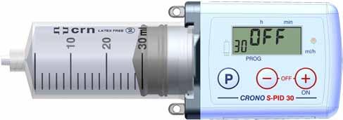
17 SECTION 5 PUMP PARTS Connector for the reservoir wings LED Eyelets to fasten the collar strap Display Buttons Pusher Anti-slip grooves Battery compartment Serial no. Quick reference CE marking 17
18 SECTION 5 CONTROL BUTTONS There are 3 control buttons. The buttons have a built-in safety delay: you must keep them pressed for several seconds before the command takes effect (use only your fingertips, do not use sharp objects). The buttons make a ticking sound when pressed. A brief acoustic signal confirms that a command is being executed. Warning The buttons have different functions depending on the following operational condition of the pump: - OFF - StoP - ON The functions of the buttons in different modes mentioned above are described in the quick reference instructions on pages and in Section 10. LED The red LED on the right of the display activates in the following circumstances: 1 - When inserting the battery and the functioning of the device is checked (see page 33). 2 - When an error has occurred (for further information please refer to pages
19 SECTION 5 LIQUID CRYSTAL DISPLAY (LCD) The liquid crystal display uses text messages and icons to provide the user with the information about the settings, the operation being performed and any errors. Four principal digits Arrow icons Battery level indicator Two secondary digits Lock indicator Drop icon Four principal digits on the display Display principal information related to the values of the settings, error information etc. Two secondary digits of the display Display: The remaining drug volume contained in the reservoir; Information related to the parameter being displayed in the four main digits; The unit of measurement of the parameter being displayed. 19
20 SECTION 5 Low Battery indicator: Displayed when the battery is nearly dead (see related section on page 21). "Drop" icon: Steady: it separates integers from decimal numbers. Flashing: the hour and minute separator. Arrow icons: A downward arrow indicates that the settings of the pump are being programmed. A flashing right arrow indicates that the parameter shown is a flow which is expressed in ml/h. PROG ml/h Minute indicator: Flashes when the remaining duration of an infusion is expressed in minutes (time left is less than 60 minutes). "Lock" indicator: Indicates that the settings are locked (L 1); i.e. they can be viewed but cannot be changed. 20
21 SECTION 5 LOW BATTERY INDICATOR The appearance of the LOW BATTERY indicator (not flashing) on the display indicates that the battery is nearly low. If the indicator remains displayed for several consecutive infusions, the LOW BATTERY message is displayed, accompanied by a beep repeated approximately every 10 seconds. In these circumstances the device is locked until the battery must be replaced. During battery replacement, when in the OFF or StoP conditions, the pump retains the current settings and the position of the pusher in its memory. If the battery needs to be changed during an infusion, the pump must be in the StoP condition. If the battery is removed when the pump is in the ON conditions, the pump is automatically re-initialized, i.e. the pusher is withdrawn until it reaches the machine zero position (pusher in contact with the syringe support) and, then repositioned to start an infusion, displaying OFF on the display. Warnings Do not use rechargeable batteries. Using other types of battery than lithium CR 123 A batteries could cause the pump to malfunction. The battery life can be influenced by the age and the temperature and circumstances of its use and storage. Ensure you always have a replacement battery available for use. If the pump is left inactive for long periods (1-2 months), you are advised to remove the battery. NOTES After you have inserted the battery, the pump runs a self-diagnostic test during which it will emit brief acoustic signals and displays all of the icons and indicators. When you have completed this phase (replacement of the battery), check that the battery compartment is properly closed. 21

22 SECTION 5 BATTERY REPLACEMENT Use a 3 Volt Lithium battery, model 123 A. To replace the battery, ensure that the pump is switched off (the display showing OFF or StoP), and then proceed as follows: 1. Open the cover of the battery compartment with the appropriate tool supplied, or by using a paper clip. 2. Pull back the cover. 3. Use the small ribbon strap (which lies under the battery) to facilitate removal of the battery. 4. Remove the discharged battery and discard it properly, using the appropriate containers. 5. Wait 10 seconds before inserting the new battery checking that it is in the correct position (see the image below) and that the ribbon strap is under the battery. 6. After you have inserted the battery, close the compartment cover. NOTES In the event that it is not possible to remove the battery using the ribbon strap, do not use an object to lever out the battery, but proceed as follows: Hold the pump and the compartment cover firmly in your one hand; Strike the palm of your other hand with the pump, to jolt the battery from the compartment; The cover is supplied with a gasket which must remain in position as indicated in the illustration. Gasket 22
23 CRONO PID CRONO PID SECTION 5 CRONO PID CRONO PID
24 SECTION 6 SETTINGS LOCK The CRONO S-PID 30 pump has 2 access configurations: - L 0 (unlocked): in this configuration you can use the control buttons to access all of the settings and parameters, and control all of the operational functions. - L 1 (locked): in this configuration you can use the control buttons to control the operational functions (switching on, priming and switching off), but cannot modify any of the settings. When the pump is set to L 1, the display shows the lock indicator. PROG PROG Before attempting to modify any of the settings, ensure that the selected access level of the pump is L 0 (OFF symbol). Warnings This access level for the functions remains in the memory, even if the battery is removed. When the settings access is L 1 (locked), any attempt to access the locked options will cause the device to beep intermittently and display a flashing "lock" indicator. The information relating to locking/unlocking of the settings lock is supplied at the back of this User guide on a plastic card and is only for use by a doctor. 24
25 SECTION 7 ERRORS AND ANOMALIES DISPLAY ACOUSTIC SIGNAL ERROR DESCRIPTION CORRECTIVE ACTION Brief beep. Operation not allowed. --- Continuous acoustic signal and flashing LED. Intermittent acoustic signal repeated approximately every 10 seconds. Intermittent acoustic signal repeated approximately every 10 seconds. Intermittent acoustic signal repeated approximately every 10 seconds. Intermittent acoustic signal repeated approximately every 10 seconds. Critical problem in the safety system. Anomaly in the motor circuit. Mechanism of the pusher blocked while withdrawing (could be caused by a foreign body preventing its movement). Pusher mechanism blocked. Motor anomaly. Press the button. Press the button. Eliminate the cause and initialize the device. Press the button. Initialize the device. Intermittent acoustic signal repeated approximately every 10 seconds (possibly accompanied by flashing LED). Communication error between the two microcontrollers. Press the button. 25
26 SECTION 7 DISPLAY ACOUSTIC SIGNAL ERROR DESCRIPTION CORRECTIVE ACTION Intermittent acoustic signal repeated approximately every 10 seconds. When a battery is inserted and at the start of every infusion, the device runs a control algorithm on the parameters stored in the memory. If an error is found, the manufacturer default settings are restored, the motor stops and an error is shown on the display. Initialize the device. Intermittent acoustic signal repeated approximately every 10 seconds. Anomaly in the safety circuit which drives the pump motor. If an error is found, the pump locks and the error is indicated. Initialize the device. Intermittent acoustic signal repeated approximately every 10 seconds. Anomaly in the pusher mechanism. Initialize the device. Intermittent acoustic signal repeated approximately every 10 seconds. Mechanism blocked because of an occlusion in the infusion line. Eliminate the cause and press button. See page
27 SECTION 7 WARNINGS Following the display of error message Er,8 and the successive initialisation, the system reverts to the factory settings (see page 29): in this event the pump settings prescribed by the doctor should be re-entered. Errors messages Er,2 and Er,7 are accompanied by the flashing LED. NOTES The displayed error messages (from Er,2 to Er,11 and OCCL) are accompanied by an acoustic signal and the system stops. In order to initialize the device when an error has occurred and the device is in the ON condition, it is necessary to remove the battery and re-insert it after about 10/15 seconds. If the error is detected again after the corrective action or initialisation of the device, contact the Canè S.p.A. Technical Support Service. 27
28 SECTION 7 INFUSION SET OCCLUSION The pump is designed to recognise when the administration of a drug has been interrupted by external means, such as, for example, the kinking of the infusion set tube and consequent occlusion. In these circumstances, the pump stops the infusion: the display indicates that an occlusion occurred accompanied by an intermittent acoustic signal every 10 seconds. While the system is still occluded, the drug is not administered: to resume an infusion, press the button after removing the cause of the occlusion. NOTES The cause of the occlusion is to be found along the infusion set line and at the point of injection. To avoid or reduce the incidence of occlusions, you are advised to use an infusion set with anti-kinking tubes. POST-OCCLUSION BOLUS The occlusion alarm is signalled when the pump detects excessive back pressure in the infusion line. This back pressure must be removed without accidently releasing the post-occlusion bolus, which could cause serious harm to the patient. The volume of the CRONO S-PID 30 post - occlusion bolus, considering only the combined volume of the pump andreservoiris approximately 1.2 ml. Warnings The volume of the bolus released after an occlusion can vary, depending on the type of catheter, the infusion set and all the other components that comprise the infusion line. Another element that could affect the volume of the released bolus after an occlusion is the presence of any air in the system. After the occlusion alarm is given, disconnect the infusion set from the patient to avoid the post-occlusion bolus being administered to the patient. 28
29 SECTION 8 FACTORY SETTINGS The pump is supplied with the following default settings: Delivery time End of infusion acoustic signal Partial volume Access level 10 h AL on (active) 30 ml L 0 (unlocked) Number of infusions 0 In flow rate mode the pump is supplied with the following settings: Flow rate End of infusion acoustic signal Partial volume Access level 3 ml/h AL on (active) 30 ml L 0 (unlocked) Number of infusions 0 29
30 PUMP SET TO OFF BATTERY INSERTION SECTION 9 QUICK REFERENCE The buttons have a built-in safety delay: you must keep them pressed for several seconds before the command takes effect. Warning These quick reference instructions are not an alternative to reading the information contained in this User guide, but offer a basic and rapid summary of the pump s functions. BUTTONS ACTIVATION DISPLAY Access all display segments Show the type of programming (flow rate/time) Access the flow rate/time selector (only possible with L 0access level) Change the flow rate/time parameter Automatic positioning of the pusher at the start of the infusion PROG PROG Switching off the pump BUTTONS SETTINGS DISPLAY The pump is switched off with L 0 access level 1 st press Access the end of infusion alarm selector PROG PROG 2 nd press Access the partial volume selector PROG / Change the value of the preceding settings 30
31 PUMP SET TO ON SECTION 9 BUTTONS SWITCHING ON DISPLAY Switching on the pump Priming phase Displaying the partial volume (if it has been set) Start of infusion Switches between display of flow rate (only in flow rate mode) and delivery time ml/h PRIMING keep pressed Priming dose (max 1.5 ml) and press simultaneously Switching off the pump SETTING THE DELIVERY TIME (t mode) Delivery time Setting the delivery time ("t" mode) / Decrease/Increase the delivery time Setting the flow rate (F mode) Delivery time PROG Display the flow rate ("F" mode) ml/h Setting the flow rate / Decrease/Increase the flow rate PROG ml/h SWITCHING OFF THE PUMP and press simultaneously Switching off the pump 31
32 END OF INFUSION SECTION 9 BUTTONS EARLY WITHDRAWAL OF THE Pusher / REA- DING OF THE NUMBER OF INFUSIONS DISPLAY EARLY WITHDRAWAL OF THE Pusher / READING OF THE NUMBER OF INFUSIONS and press simultaneously press for 4 seconds Interruption of an active infusion and withdrawal of the pusher to the start position of the infusion Number of infusions performed (PC: Partial Counter) BUTTONS END OF INFUSION DISPLAY End of infusion Automatic withdrawal of the pusher Switching off the pump 32
33 SECTION 10 PUMP INITIALISATION If the battery is removed when the display shows OFF, when you re-insert the battery the pump runs the initialisation sequence, during which it: 1. Runs a self-diagnostic test, emitting a series of brief acoustics signals, flashing the red LED and displaying all the icons. 2. The display shows the previously selected programming mode. 3. The display shows OFF. NOTES The pump is supplied with a new battery already inside the pump. For instructions on how to install the battery, see page 22. You are recommended to initialise the pump if it has been left unused for a long period of (more than 1-2 months) and the battery is not removed. If the battery is removed when the display shows StoP, re-inserting the battery makes the pump run a self-diagnostic test (as explained in Step 1). Then, the display shows StoP. Warning The setting of the pump is the doctor's responsibility, who will choose the most suited parameters to carry out the therapy required for the patient. 33
34 SECTION 10 PUMP SETTINGS WHEN INSERTING BATTERY If the battery is removed when the display shows OFF, when you reinsert the battery you can set the programming mode of the pump: 1 - by flow rate, expressed in ml/h if you select F or, 2 - by time, expressed in hours and minutes if you select "t. Procedure: 1 - Remove the battery when the device is set to OFF and re-insert the battery. 2 - The display shows all the symbols. 3 - The device simultaneously runs a self-diagnostic tests during which it emits an acoustic signal. 4 - Subsequently, the display shows F (flow rate) or t (time) programming mode: 5 - After pressing the button the symbol flashes for 9 seconds. By keeping the button pressed it is possible to switch from one option to another one. PROG 6 - If these buttons are not pressed for about 9 seconds, the device memorises the selected parameter. PROG 7 - Subsequently, the display shows OFF. NOTE Setting the programming mode is only possible with the L 0 access level and only at the start of an infusion. Choosing whether to program the pump by flow rate or by time is the responsibility of the doctor, who will decide on the most suitable method. 34 Warning
35 SECTION 10 PUMP SETTINGS SEQUENCE WITH THE PUMP OFF CONDITION When the device is set to OFF, the following parameters can be set: 1 - End of infusion acoustic signal. 2 - Partial volume. In the OFF condition the parameters can be selected only in the following circumstances: - Setting lock unlocked; - At the start of a new infusion (partial or total). To access the settings, press the button for about 3 seconds: the display shows the settings for the end of infusion acoustic signal. You can change the parameter settings (activate/de-activate) while the display is flashing using the and buttons. PROG PROG Press the button again to display and set the partial volume. You can change the parameter settings (activate/ de-activate) while the display is flashing using the and buttons. PROG NOTE When the settings lock is on (L 1), if any attempts are made to change the parameter then the display will show the flashing lock symbol and beep several times. 35
36 SECTION 10 SETTING OF END OF INFUSION ACOUSTIC SIGNAL 1. In the OFF condition, by pressing the button the pump starts the mode for selecting the end of infusion acoustic signal. 2. When the value flashes, select a new value by using the and buttons. Selecting off disables the warning and the end of infusion acoustic signals; selecting on activates the warning of end of infusion acoustic signals, which will sound 10 min. and 5 min. before the end of the infusion, and at the end of the infusion. PROG PROG 3. Do not press any button for 10 seconds, and the setting phase will end. The displayed flashing value becomes fixed and then OFF is displayed. 4. By pressing the button while the value of the previous settings is still flashing it is possible to set the following parameter: SETTING THE PARTIAL VOLUME (see page 37). PROG NOTES When the settings lock is on (L 1), if any attempts are made to change the parameter then the display will show the flashing lock symbol and beep several times. The end of infusion acoustic signal can be set also in the StoP condition. 36
37 SECTION 10 Setting the partial volume The partial volume function is used when the therapy requires an infusion with less than 30 ml. The partial volume can be set from 1 cc to 30 cc in increments of 1 cc. To set this parameter, press the button again, while the previous parameter is flashing. The partial volume function can only be set before starting a new infusion, either a complete one (30 ml) or a partial one. Proceed as follows: 1. The display shows a flashing value of the volume, preceded by cc, which indicates the unit of volume (1 cc = 1 ml). 2. Press the button to decrease the value and the button to increase it. Each change is indicated by an acoustic signal. PROG PROG 3. Do not press any button for 10 seconds and the setting phase will end. The display will show P,cc. 4. The pusher is automatically positioned at the configured partial volume value. An intermittent acoustic signal is emitted while it does so, and the pump displays - in real time - the actual volume corresponding to the pusher position When the pusher is in the correct position, the display shows OFF. The selected partial volume value will be shown at the bottom left of the display. 37
38 SECTION 10 NOTES The set partial volume value is automatically saved in the pump memory. At the end of the infusion, the pusher returns to the position corresponding to the set partial volume value. The partial volume value can be interrupted by simultaneously pressing the and buttons. - if the pusher was still advancing, the device switches off (the display shows StoP) and the pusher remains in the same position when the infusion was interrupted: the partial volume value is not stored in the device memory and the previous value will not be overwritten. - If, however, the pusher was in the process of being withdrawn, the display shows OFF and P,cc alternately. The only possible operation is to continue the withdrawal of the pusher by pressing the button. The pusher withdraws to the position of the partial volume settings. Press the and buttons simultaneously while P,cc is shown to cancel the storing of the partial volume. Warnings This operation must not be carried out with the infusion set connected to the patient. A partial volume cannot be set while an infusion is in progress. The partial volume settings remain in the device memory even if the battery is removed. If the battery is removed when the pump is set to OFF/StoP, the partial volume remains in the device memory and the pusher is not withdrawn. If the battery is removed when the device is in the ON, the pusher returns to the infusion start position after a reset and then repositions itself according to the memorised partial volume. SETTINGS IN ON CONDITION When the device is set to ON, the following parameters can be set: 1 - Delivery time (if time mode has been selected upon battery insertion). 2 - Flow rate (if flow rate mode has been selected upon battery insertion). 38
39 SECTION 10 SETTING THE DELIVERY TIME This function is available only if the t (time) function has been selected upon battery insertion. Time value can be set from 25 min. to 300 h as follows: - From 25 min. to 1 h in increments of 5 min. - From 1 h to 30 h in increments of 15 min. - From 30 h to 300 h in increments of 120 min. (2 h) You can change the time parameter during an infusion. Procedure: 1 - Switch on the pump by pressing the button. 2 - Pressing the button and the pump allows setting the delivery time the time displayed begins to flash. 3 - You can change the parameter while it flashes using the or buttons. 4 - Not pressing these buttons for about 9 seconds or pressing the button will memorise the parameter that has been selected and the infusion recommences. PROG NOTES If you keep either the or buttons pressed, it is possible to change the values of delivery time quickly. If the settings lock is active, the function to set the delivery time is not available; if attempts are made to change the parameter, then the display will show the flashing lock symbol and will emit an intermittent acoustic signal. Warning If a partial volume is used, the pump can perform an infusion in less time compared to the specified minimum time of 25 minutes. 39
40 SECTION 10 SETTING THE FLOW RATE This function is available only if the F (flow rate) function has been selected upon battery insertion. The flow rate can be set from 0.1 to 75 ml/h as follows: - From 0.1 ml/h to 1 ml/h in increments of 0.01 ml/h - From 1 ml/h to 10 ml/h in increments of 0.1 ml/h - From 11 ml/h to 75 ml/h in increments of 1 ml/h You can change the flow rate parameter only during an infusion. Procedure: 1 - Switch on the pump by pressing the button. 2 - Press the button and the pump allows for setting the flow rate: The display shows the flashing value of the flow rate. 3 - You can change the parameter while it flashes using the or buttons. 4 - Not pressing these buttons for about 9 seconds or pressing the button will memorise the parameter that has been selected and the infusion recommences. PROG ml/h If you press the button, the display toggles between the delivery time and the flow rate, and vice versa. NOTES If you keep either the or button pressed, it is possible to change the values of the flow rate quickly. If the settings lock is active, the function to set the flow rate is not available. Any attempt to change the parameter results in the display showing the flashing lock icon accompanied by some short acoustic signals. 40
41 SECTION 10 SWITCHING ON THE PUMP From the OFF condition, press the will give a brief beep and display: button. The pump Pr (priming function) the display shows Pr. (see page 42); Having carried out the priming, or if the pump is turned on to resume the infusion from the StoP condition, the display shows the following in sequence: - The partial volume value (if it has been set) - The value of the delivery time or of the flow rate ml/h THE PUMP IN ON condition When the pump is working, the display shows the flow rate value in ml/h or the delivery time in hours and/or minutes: From 300 h to 100 h the delivery time decreases hour by hour. From h to 1 minute the delivery time decreases minute by minute. Warnings Before starting an infusion: Inspect the infusion line to ensure there are no folds, closed clamps, or other occlusions in the beginning of the line. Expel any air bubbles. 41
42 SECTION 10 PRIMING THE INFUSION SET LINE The priming function allows for filling the infusion set line with the drug contained in the reservoir. The volume available for priming is 1.5 ml. The priming function is enabled when you switch the device on and the pusher is in the infusion start position, regardless of whether the settings lock is on or not. The priming procedure is as follows: 1. Turn on the device by pressing the button. 2. The display shows Pr. There are three options: a. Postpone the priming. b. Cancel the priming. c. Perform the priming. a. Postpone the priming Wait for 10 seconds, the pump will turn off automatically. b. Cancel the priming Press the button again: the pump begins the infusion and the display shows the time remaining until the end of the infusion. c. Perform the priming Press and hold down the button: the pump delivers the priming dose until you release the button. The display then shows flashing letter P in the secondary digits, followed by the number of ml delivered. The priming function can be interrupted by releasing the button. The display shows Pr again. In this way it is again possible to postpone, cancel or perform the priming function as described above. The procedure can be repeated up to a maximum of 1.5 ml. 42
43 SECTION 10 NOTES If you keep the button pressed, the pump delivers the priming dose, giving an acoustic signal every time 0.5 ml is administered consecutively. (e.g ml). Proceed until the infusion set is completely filled and a few drops of the drug leak out of it. If, after the priming indication is displayed, the buttons are not pressed again for 10 seconds, the display shows OFF. Warnings Do not prime the infusion set with the tube connected to the patient. The priming function must only be performed with the reservoir connected to the infusion set, but before inserting the needle into the infusion site. Before beginning an infusion, check that there are no air bubbles in the infusion line, and if need be, expel the ones found. Alternatively, use a vented filter. 43
44 SECTION 10 END OF INFUSION Ten minutes before the end of the infusion (only if AL is active), the device gives an intermittent acoustic signal lasting 2 seconds. This signal is repeated twice at 5 minutes from the end of the infusion and at the end of it: the display shows the End message. After a few seconds, the pusher starts withdrawing until it reaches the start position of the infusion. When the withdrawal is complete, the display shows OFF and the pump is ready for another infusion. NOTE The pusher withdrawal time for a 30 cc volume is about 6 minutes. It is proportionately less for lower volumes. SWITCHING OFF THE PUMP To switch off the pump during an infusion, press the and the buttons simultaneously. The display will show StoP. If the pump is switched off during an infusion, the device will emit a series of 10 short beeps every 10 seconds, and the display will be flashing with StoP. To stop the acoustic signal, press button. This acoustic signal will be repeated every time the device is switched off during an infusion. 44
45 SECTION 10 WITHDRAWING THE Pusher 1. Withdrawal of the pusher before the end of the infusion This function allows for the interruption of an active infusion, withdrawing the pusher to the infusion start position. To stop an active infusion, do the following: Stop the pump by pressing the and buttons simultaneously. Turn off the pump by pressing the and buttons for a few seconds: The display shows End for 10 seconds and then begins to withdraw the pusher. During these 10 seconds when the display shows End you can cancel the withdrawal request by pressing the and buttons together. 2. Withdrawal of the pusher at the end of the infusion At the end of the infusion the display shows End and the pump emits an acoustic signal for a few seconds. The pusher remains still in the infusion end position for about 10 seconds, after which it begins to withdraw until it reaches the infusion start position. When the withdrawal is complete, the display shows OFF and the pump is ready for another infusion. Pusher in motion While the pusher is being withdrawn, the display shows the pusher continuous withdrawal icon. 45
46 NOTE SECTION 10 The function to withdraw the pusher can be interrupted by pressing the and buttons together. The display then alternates between End and OFF. At this point the only active button is the button. When you press it again, the pump resumes the withdrawal of the pusher. Warning Do not remove the reservoir until the pusher has been withdrawn to the infusion start position. 46
47 SECTION 10 DISPLAYING THE SETTINGS This function allows for displaying the programmed pump settings. To display the pump settings, the pump must be set to OFF or StoP. If the settings are displayed in the L 0 mode (settings lock not active) and flash, it is possible to reset them. If the settings are displayed in L 1 condition (settings lock active with the display showing the lock icon), the parameters will not flash and cannot be modified. Proceed as follows: 1. Press the button for about 1 second: The display will show the menu for selecting the end of infusion alarm. 2. Press the button again and the display will show the selected partial volume. 3. Do not press any button for about 9 seconds, and the setting phase will end. The display will show OFF or StoP. 47
48 SECTION 10 Resetting the number of partial infusions The device contains two infusion counters: one for a partial count which can be reset, and another for a total count. To reset the number of partial infusions, proceed as follows: 1 - Press the button for about 4 seconds, until the display shows the number of partial infusions PC (Partial Counter). 2 - Without releasing the button, press button : The number of partial infusions shown on the display starts flashing. 3 - Press the button once more to invoke the programming mode (the down arrow is displayed). PROG 4 - Press either the or the button to reset the number of partial infusions. Alternatively, press the button to display the total count of infusions performed: tc (Total Counter). PROG 5 - Press the button again to display the pump firmware release: re (Release). 6 - If you do not press anything for about 10 seconds or press the button again, the display shows OFF. 48


49 SECTION 11 RESERVOIR PARTS The CRONO S-PID 30 pump uses a dedicated 30 ml reservoir, model CRN CRONO Syringe. The reservoirs are: single-use, non-pyrogenic to be used only if the packaging is undamaged. Reservoir body Piston Rod Luer-Lock cap Needle cover Needle Warnings For safety reasons, you are recommended to use the reservoir of the original CRN CRONO Syringe. The use of any other type of reservoir could damage the pump and harm the patient. Canè S.p.A. disclaims all responsibility if the device is used with a nonoriginal reservoir, i.e. other than the one recommended. LUER-LOCK CAP FUNCTIONS After the reservoir has been filled, it facilitates unscrewing of the piston rod, avoiding spillage of the drug. Luer-Lock cap It facilitates the correct connection between the pump pusher and the rubber piston of the reservoir. It protects the drug inside the reservoir in case it is not used immediately. 49
 Tube length not more than 90 cm Anti-kinking tube INFUSION SET PARTS Adhesive Female Luer-Lock connector Needle Needle cover Tube NOTE The images show the Neria TM,")

50 SECTION 11 INFUSION SET You are recommended to use an infusion set with the following characteristics: Tube with reduced internal volume (ideal 0.1 ml, maximum 0.62 ml) Tube length not more than 90 cm Anti-kinking tube INFUSION SET PARTS Adhesive Female Luer-Lock connector Needle Needle cover Tube NOTE The images show the Neria TM, infusion set from Unomedical, a Convatec Company. Warning Refer to the User guide supplied with the device for information on using the infusion sets. Y-SET Using a Y-SET you can infuse the drug in two different infusion sites at the same time. Blue male Luer- Lock connector Female Luer-Lock connector Male Luer-Lock cap Female Luer- Lock caps Y-connector 50
51 SECTION 11 Warnings The Y-SET does not guarantee that the drug is evenly distributed in both infusion sites. Refer to the product sheet supplied with the device for information on using the Y-SET. MULTIPLE INFUSION SET You can use a two-way or multiple infusion set as an alternative to the Y-SET. MULTIPLE INFUSION SET PARTS Female Luer-Lock connector Tube Adhesive NOTE The images show the Neria TM multiple infusion set produced by Unomedical, a Convatec Company. Warning Refer to the User guide supplied with the device for information on using the infusion sets. 51


52 SECTION 11 PREPARATION OF THE RESERVOIR AND CONNECTION TO THE PUMP 1. Screw the needle into the reservoir in a clockwise direction and remove the needle PREPARATION cover. OF THE RESERVOIR 2. Fill the reservoir, aspirating the liquid slowly and checking that the quantity of the drug does not exceed its capacity or any partial volume you may have set. 3. Screw the Luer-Lock cap to the reservoir (a) and then unscrew the rod, rotating it counter-clockwise (b) fairy quickly. 4. Insert the reservoir into the pump. The rubber piston will be inserted into the pusher. Rotate it clockwise through 90 and it will click and engage with the pusher. 5. Insert the cone of the infusion set over the reservoir. a. b


53 SECTION 11 INSERTION OF THE RESERVOIR INTO THE PUMP Insert the dedicated CRN reservoir into the pump and engage it by rotating it 90 clockwise; a click confirms it has engaged Front view

54 SECTION 11 Warning Before filling the reservoir Unscrew and screw back the piston rod to facilitate its unscrewing after you have filled the reservoir. Filling the reservoir The liquid must be aspirated slowly. Do not fill the reservoir more than the maximum level allowed. The rod must be unscrewed fairly quickly. Inserting the reservoir into the pump To avoid any leakage of the drug while the reservoir is being inserted into the pump, you can use the infusion set as an alternative to the Luer-Lock cap indicated on page 49. When making the connection, avoid exerting any pressure on the reservoir walls, because this could cause the liquid to leak from the piston rings. While filling the reservoir and inserting it into the pump, a small leakage might occur between the first and second ring on the rubber piston; this does not compromise either the correct operation of the reservoir or the delivery of the drug. 54


55 SECTION 11 PUMP CONFIGURATION IMAGES FOR INFUSIONS AT MULTIPLE SITES: 1 - Y-SET PUMP 2 - TWO-WAY PUMP SET 55

56 SECTION 11 INFUSION SITES The images below show the recommended infusion sites. You are recommended to change the injection site after every infusion to avoid skin irritations. PREPARING FOR THE INFUSION Before preparing for the infusion, you are recommended to adopt the following precautions: 1. Wash your hands; 2. Prepare a clean working environment. Warning Always work in antiseptic conditions to reduce the risk of infection to the minimum. 56

57 SECTION 11 The images refer to the Neria TM infusion set from Unomedical, a Convatec Company. Disinfect the infusion site following the instructions of the relevant medical personnel. Ensure that the area of the infusion site is dry before inserting the subcutaneous needle. Connect the infusion set to the reservoir. Hold the infusion set by the wings. Prime the infusion line manually or use the priming function of the pump. Ensure there are no air bubbles in the infusion line. Warning When you are priming the infusion line and are preparing to insert the needle below the skin, hold the set with the needle pointing downwards to ensure that no drug can come into contact with the protecting adhesive paper. Remove the protective adhesive paper. 57

58 SECTION 11 Remove the needle cover, extracting it with care, before inserting the needle. Warning Be careful not to touch the Neria TM needle when you remove the protection. It is important to lift a fold of skin, to reduce the risk of positioning the needle in a muscle. Pinch the skin with your fingers at the chosen infusion site before inserting the needle, which you do by taking the protective wings of the infusion set with the other hand and inserting the needle vertically. Warning Do not administer immunoglobulins intravenously; if they are accidentally administered to a blood vessel or capillary, the patient could suffer an anaphylactic shock or thromboembolic events. Always check this before continuing with an infusion. Press firmly on the adhesive to fix it to the skin. Check the infusion site frequently to ensure that the needle remains in the correct position. 58


59 SECTION 12 HOW TO USE THE ACCESSORIES SUPPLIED The following figures give an indication of how to use the standard accessories supplied with the pump. PUMP CARRIED AROUND THE NECK The pump worn with a collar strap and a fabric case. FASTENING THE PUMP COLLAR STRAP SEQUENCE


60 SECTION 12 PUMP ATTACHED AT THE WAIST The pump worn with an elastic belt and a fabric case. 60
61 SECTION 13 GENERAL WARNINGS The device can be damaged by liquid infiltration, so it must not be used while in the bath or the shower etc. If the device accidentally becomes wet (for example, drops of the drugs, or overnight bedwetting), you must ensure it is checked by the Canè S.p.A. Service Centre. The device must be kept away from: - Sources of heat (radiators, gas rings, stoves). - The direct rays of the sun. - Strong electromagnetic fields (magnets, loudspeakers, mobile devices), details are supplied in APPENDIX 6. - Ionizing radiation. - Ultrasound devices. - MRI devices. The device does not need sterilising. Do not freeze the CRN reservoir with the drug still in it. The device must not be placed in a fridge or freezer. The device must not be placed in an oven or microwave. Reservoirs, infusion sets, needles, filters and all consumable materials must be disposed of in an appropriate way, using containers designed for this purpose. If you do not observe the above instructions, the device could malfunction, with potentially serious consequences for the user. 61
62 SECTION 13 MAINTENANCE The technical characteristics of the device make it extremely simple to maintain. If the device is damaged, you are recommended to have it checked by Canè S.p.A. Customer Support Service, before re-using it. The external surfaces can be cleaned with a lightly dampened soft cloth, using a mild detergent or disinfectant. GENERAL WARNINGS Do not immerse the pump in detergent solutions or water. Avoid getting liquids inside the pump. If the device gets wet, immediately try to dry it with absorbent paper. Do not clean the pump with acetone, solvents or abrasive detergents. Do not sterilise the pump. STORAGE If the device is not used for a period more than one or two months, you are recommended to remove the battery and put the pump away in its case in a dry place at room temperature. DISPOSAL At the end of the expected life of the pump, contact Canè S.p.A. Customer Support Service, which will provide you with necessary instructions about the disposal of the device. Reservoirs, infusion sets, needles, filters and all consumable materials must be disposed of in an appropriate way, using containers designed for this purpose. EXPECTED PUMP LIFE The pump is expected to last for 4 (four) years from its purchase date. For safety reasons you should not continue using it after this period. 62
63 SECTION 13 SUPPORT The device must only be repaired by Canè S.p.A. Customer Support Service. You are recommended, before sending the device, to contact: Customer Support Service Canè S.p.A. Medical Technology Via Cuorgnè, 42/a Rivoli (Turin) - Italy Tel Fax Canè S.p.A. Online Internet: service@canespa.it 63
64 SECTION 13 GUARANTEE Canè S.p.A. guarantees that the product is free from any material or manufacturing defects for a period of 2 (TWO) YEARS from the original date of purchase. If, in the course of this guarantee period, any material or manufacturing defects are identified, Canè S.p.A. will repair or substitute the defective components according to the terms and conditions herein, without any charge for labour or parts; the client is responsible for the costs of sending the pump to the Canè S.p.A. Customer Support Service. Canè S.p.A. reserves the right to change the characteristics or model of its devices, without being under any obligation to make corresponding modifications to devices already manufactured and sold. Conditions: 1. The guarantee is valid only if the defect is reported within the period of the guarantee. 2. This guarantee does not extend to any costs and/or defects following modifications or adaptations made to the product, without prior written authorisation by Canè S.p.A. Canè S.p.A. disclaims all responsibility either to the purchaser or to third parties for damage that occurs to persons or things as a result of improper operation of the device, for uses of the device for which it was not designed and for the non-observance of the instructions provided in the User guide. The purchaser undertakes to indemnify Canè S.p.A. from any claims by third parties with respect to the above. 3. This guarantee is not valid if the model or serial number of the product have been modified, erased, removed or have in any way been made illegible. 64
65 SECTION The following are excluded from the guarantee: Periodic maintenance Damage resulting from improper use, including but not limited to: - Incorrect power supply - Use of the product for purposes other than those for which it is designed - Repairs performed by unauthorised personnel or by the client Accidental and unintentional events, such as liquid spills and falls Natural events and malicious or negligent acts The standard equipment supplied with the pump. 5. Canè S.p.A. undertakes to perform repairs on the device for a period of not more than 4 (four) years from the date of purchase. After that period, Canè S.p.A. has no further obligations to make repairs. Canè S.p.A. disclaims all responsibility either to the purchaser or to third parties for damage that occurs to persons or things as a result of the use of the device after 4 (four) years from the date of purchase. 6. After the guarantee period is expired, support will be provided by Canè S.p.A. with the customer bearing the subsequent costs of replaced parts, labour and transport in effect at the time. 7. The company disclaims any liability with respect to the patient and/or third parties for any health problems and/or inconvenience resulting from the period when the device is being repaired. 8. The company disclaims any liability with respect to the patient and/or third parties for any problems and/or delays associated with the shipping of the device. 65
66 SECTION 14 DECLARATION OF CONFORMITY 0476 The Company Canè S.p.A., with headquarters in Via Cuorgnè, 42/a Rivoli (Turin) - Italy, manufacturer of the electromedical device CRONO S-PID 30 ambulatory infusion pump with reservoir for drug administration. Serial no. declares that the device conforms to the essential requirements of Appendix I of Directive 93/42/EC, modified by Directive 2007/47/EC, as per certificate MED 9813 provided by the Notifying Body no according to Appendix II of the same Directive, and is released to the market in compliance with the corresponding laws of the individual European member states. Rivoli, 13/07/2012 The Chairman 66
67 APPENDICES 67
68 APPENDIX 1 ICONS USED ON THE PUMP SN IP 42 Serial no. of the pump IP protection rating 1 st digit (4) = protection from solid objects larger than 1 mm. 2 nd digit (2) = protection from water droplets sprayed at an angle up to 15º degrees CE marking Electromedical device Electrical classification: Class I, Type BF. Warning: read instructions before use Separated waste collection of electrical and electronic equipment In accordance with article 13 of Legislative Decree no. 151 of 25 July 2005 Implementation of Directives 2002/95/EC, 2002/96/EC and 2003/108/EC concerning the restriction of the use of certain hazardous substances in electrical and electronic equipment, as well as the disposal of waste. The symbol of the crossed out waste bin on the product and its packaging indicates that at the end of its life, the product must be disposed of separately from other waste. Sorted waste disposal of products at the end of their life is organised and managed by the manufacturer. Users wishing to dispose of this device must therefore contact the manufacturer (or the appropriate local distributor) and use the system which has been devised to allow for the separate disposal of devices at the end of their life. A proper differentiated collection system for devices destined for recycling, treatment and environmentally compatible disposal helps reduce the potentially negative impacts on the environment and health, and facilitates the reuse or recycling of the materials from which the device is constructed. The illegal disposal of a product is punishable according to the laws currently in force. Note: The symbol displayed on the product label is, for obvious reasons of space, reduced and simplified with respect to the specifications in the reference standard CENELEC EN
69 APPENDIX 1 ICONS USED ON THE Reservoir BLISTER PACK i 0123 Read the instructions CE marking Recyclable 2 Use only once PYROGEN Non-pyrogenic Keep dry Keep away from sunlight Expiry date STERILE EO Sterilised with ethylene oxide PP Polypropylene LOT Batch code REF Reference No. NEEDLE Needle size 69


70 APPENDIX 2 OPTIONAL ACCESSORIES AVAILABLE ON REQUEST 1. Vertical leatherette case, similar to a mobile phone case. Detail of the belt clip Detail of the opening system with an aperture for the infusion set Item code: CM/15/A Colours: Dimensions: about 16 x 5.5 x 4 cm Weight: about 60 g 70


71 APPENDIX 2 2. Horizontal leatherette case, similar to a spectacle case. Detail of the belt clip Item code: CM/23/A Colours: Dimensions: 16 x 5.5 x 4 cm Weight: about 50 g 71
Crono PAR. Ambulatory infusion pump NEW MODEL USER GUIDE
 Crono PAR Ambulatory infusion pump NEW MODEL USER GUIDE Canè S.p.A. Medical Technology Via Cuorgnè 42/a 10098 Rivoli (TO) Italy Tel.+39 011 9574872 - Fax +39 011 9598880 www.canespa.it - mailbox@canespa.it
Ambulatory infusion pump USER GUIDE
 0476 USER GUIDE Ambulatory infusion pump US Federal law restricts this device for sale by or on order of a physician. Canè S.p.A. Medical Technology Via Cuorgnè 42/a 098 Rivoli (TO) Italy Tel.+39 011 9574872
PATIENT USER GUIDE CANÈ
 PATIENT USER GUIDE PATIENT USER GUIDE CANÈ S.p.A. Medical Technology Via Cuorgnè 42/a 098 Rivoli (TO) Italy Tel.+39 011 9574872 - Fax +39 011 9598880 www.canespa.it - mailbox@canespa.it Manual code: MAN
Making Life Easier Easypump II
 Making Life Easier Easypump II The elastomeric pump system for short- and long-term infusion therapy Elastomeric Infusion Systems Technical Guide Easypump II Disposable Elastomeric Infusion Pump System
BODYGUARD 2CH TWIN CHANNEL INFUSION PUMP
 BODYGUARD 2CH TWIN CHANNEL INFUSION PUMP The BodyGuard 2CH Twin Channel Infusion Pump is an ambulatory multi-therapy pump suitable for hospital and homecare environments with five infusion programs (continuous,
Nimbus II PainPRO Ambulatory Infusion Pump
 Nimbus II PainPRO Ambulatory Infusion Pump Patient Manual PCA Mode Infusions Read this entire manual prior to operating the Nimbus II PainPRO Ambulatory Infusion Table of Contents Section 1: General Description...
CADD-Micro. Model 5900 Operator s Manual. Note: Colors are Black and Cyan (as second color) Deltec. Ambulatory Infusion Pump
 Deltec. Ambulatory Infusion Pump") Note: Colors are Black and Cyan (as second color) CADD-Micro Ambulatory Infusion Pump Overview Programming Examples Model 5900 Operator s Manual Deltec SIMS Deltec, Inc., St. Paul, MN 55112 U.S.A. 87 Overview
Note: Colors are Black and Cyan (as second color) CADD-Micro Ambulatory Infusion Pump Overview Programming Examples Model 5900 Operator s Manual Deltec SIMS Deltec, Inc., St. Paul, MN 55112 U.S.A. 87 Overview
The Univentor 1250 Anaesthesia Unit
 THE UNIVENTOR 1200/1250 ANAESTHESIA UNIT The Univentor 1250 Anaesthesia Unit TABLE OF CONTENTS EDITION 1 Section 1 - WARRANTY & SERVICE 1.1. WARRANTY 2 1.2. DAMAGED SHIPMENTS 2 1.3. SERVICE 2 Section 2
Roller AC Servo System
 Safely Instruction Roller AC Servo System HMI-15 User Manual Please read this manual carefully, also with related manual for the machinery before use the controller. For installing and operating the controller
EASYPUMP II THE FLEXIBLE SOLUTION FOR SHORT AND LONG TERM INFUSION THERAPIES
 THE FLEXIBLE SOLUTION FOR SHORT AND LONG TERM INFUSION THERAPIES CONTENT 4 PATIENT INFORMATION 5 Patient data 6 Treatment monitoring 7 Further notes 8 PRODUCT INFORMATION 9 Easypump II 9 Working principle
A4s Operation Manual
 A4s Operation Manual Safety Instruction Please read this manual carefully, also with related manual for the machinery before use the controller. For installing and operating the controller properly and
OXY Integral. INTERCON ENTERPRISES INC Tel: Fax: Internet:
 OXY Integral INTERCON ENTERPRISES INC Tel: 800 665 6655 Fax: 604 946 5340 E-Mail: sales@intercononline.com Internet: www.intercononline.com Manual Integral 2006 1 INDEX 2-3 PREFACE 4 INTRODUCTION 5 Principle
6800 Maintenance Instruction System Flush Procedure
 Equipment Required FA74005 FA65318 FA900005 FA900003 Damper Drain Tube 6800 Cover Removal Tool Beaker 0.25 Litre Solvent Cleaning Bottle FA940021 Syringe Polypropylene 50 ml as required FA999045 Gloves
Nimbus II PainPRO Ambulatory Infusion Pump
 Nimbus II PainPRO Ambulatory Infusion Pump Patient Manual PCA Mode Infusions Read this entire manual prior to operating the Nimbus II PainPRO Ambulatory Infusion Table of Contents Section 1: General Description...
SomnoSuite FAQ. Setup. Calibration 4. What are the calibration requirements for the SomnoSuite? Settings
 SomnoSuite FAQ V1.3 January 2015 Setup 1. How do I connect the SomnoSuite to my oxygen source? 2. Is there a way to speed up the downward movement of the pusher block when setting the empty position? 3.
Introduction. Medley TM Medication Safety System. Alaris Medical Systems
 Medley TM Medication Safety System Alaris Medical Systems Introduction The ALARIS Medley Medication Safety System is designed to help you provide the best possible patient care, by avoiding potential adverse
PATIENT USER GUIDE CANÈ
 PATIENT USER GUIDE PATIENT USER GUIDE CANÈ S.p.A. Medical Technology Via Cuorgnè 42/a 098 Rivoli (TO) Italy Tel.+39 011 9574872 - Fax +39 011 9598880 www.canespa.it - mailbox@canespa.it Manual code: MAN
Troubleshooting Guide Aquarius
 Low Access Pressure Access pressure has dropped below the lower alarm limit of 0 to - 250mmHg Blood pump is off Blood flow is too low Turn blood pump on Check blood flow rate. Consider increasing the blood
A4 Operation Manual. Fig.1-1 Controller Socket Diagram
 A4 Operation Manual Safety Instruction Please read this manual carefully, also with related manual for the machinery before use the controller. For installing and operating the controller properly and
Digital Ear Thermometer
 Adtemp TM Digital Ear Thermometer 421 Digital Ear Thermometer Instruction Manual PLEASE NOTE: THIS MEDICAL INSTRUMENT MUST BE USED ACCORDING TO INSTRUCTIONS TO ENSURE ACCURATE READINGS. Questions? Call
Instructions for Use
 Select-380 T-Auto T-Auto Contents Page Instructions for Use Ref: 3.0 IFU 380 T-Auto Mar 18 2 Schematic layout of the doser 3 Quick-fit instructions 4 Description/Installation/Operation Pump tubes & Water
HUNTER Beeper Collar Manual
 HUNTER 2000- Beeper Collar Manual For a better performance: Use only Duracell batteries Each adjustment affects the duration of the batteries The battery contacts must be kept clean The thread of the Beeper
Instruction Manual for Configura Cushionair Portable Pump
 Instruction Manual for Configura Cushionair Portable Pump Fitted with battery powered pump, suitable for Configura Portable chairs V E R S I O N O N E M A Y 2 0 1 6 Contents Introduction 3 Set up of Cushionair
Pipettor. User Manual
 Pipettor User Manual Product Code Description Single Chanel Pipettor Variable 550.002.055 Volume 0.5 to 10ul 550.002.060 2 to 20ul 550.002.065 10 to 100ul 550.002.070 20 to 200ul 550.002.075 100 to 100ul
BOC: Living healthcare. Manual. LIV IQ BOC Integrated Valve with digital display portable delivery system for Medical Oxygen. BOC: Living healthcare
 BOC: Living healthcare Manual LIV IQ BOC Integrated Valve with digital display portable delivery system for Medical Oxygen. BOC: Living healthcare 02 Manual LIV IQ Oxygen Manual LIV IQ Oxygen 03 Contents.
UNITY 2 TM. Air Server Series 2 Operators Manual. Version 1.0. February 2008
 UNITY 2 TM Air Server Series 2 Operators Manual Version 1.0 February 2008 1. Introduction to the Air Server Accessory for UNITY 2...2 1.1. Summary of Operation...2 2. Developing a UNITY 2-Air Server method
INSTRUCTION MANUAL. Automatic Blood Pressure Monitor with Fit Cuff. =Fit Cuff=!"#$% IA1B. Model
 IA1B INSTRUCTION MANUAL Automatic Blood Pressure Monitor with Fit Cuff =Fit Cuff=!"#$% Model IA1B Contents Introduction... 2 Notes on Safety... 3 Know Your Unit... 5 Quick Reference Guide... 7 Initial
RayPette Plus Autoclavable Pipette. User Manual
 RayPette Plus Autoclavable Pipette User Manual CONTENTS 1. YOUR NEW PIPETTE... 1 1.1. Adjustable volume pipettes... 1 1.3 Fully autoclavable... 2 2. UNPACKING... 3 3. INSTALLING THE PIPETTE HOLDER... 4
The pipettes cover a volume range from 0.1µl to 10ml.
 CONTENTS 1. YOUR NEW PIPETTE 1 1.1. Adjustable volume pipettes 1 1.2. Fixed volume pipettes 2 1.3 Fully autoclavable 3 2. UNPACKING 3 3. INSTALLING THE PIPETTE HOLDER 4 4. PIPETTE COMPONENTS 5 5. PIPETTE
Pedometer with PC download. Model: FB322 OVERVIEW FRONT VIEW INDEX
 OVERVIEW FRONT VIEW Pedometer with PC download INDEX Model: FB322 Introduction...1 Overview...1 Front view...1 Back view battery compartment...1 LCD screen...1 Getting started...2 Setting the device...2
VERTICAL AIR COMPRESSORS
 VERTICAL AIR COMPRESSORS MODEL NO: VE15C150, VE18C150, VE25C150 PART NO: 2226010, 2226020, 2226025 OPERATION & MAINTENANCE INSTRUCTIONS LS0715 INTRODUCTION Thank you for purchasing this CLARKE Vertical
VERTICAL AIR COMPRESSORS
 VERTICAL AIR COMPRESSORS MODEL NO: VE11C150, VE15C150, VE18C150 PART NO: 2226005, 2226000, 2226015 OPERATION & MAINTENANCE INSTRUCTIONS LS0615 INTRODUCTION Thank you for purchasing this CLARKE Vertical
AQUADEX FLEXFLOW SYSTEM QUICK REFERENCE GUIDE
 AQUADEX FLEXFLOW SYSTEM QUICK REFERENCE GUIDE AQUADEX FLEXFLOW SYSTEM DISCLAIMER The quick reference guide is not intended to replace CHF Solutions, Inc. Aquadex FlexFlow Direction For Use (DFU). Always
Peristaltic Infusion Pump AP 31P OPERATOR S MANUAL
 Peristaltic Infusion Pump AP 31P Version 4.5 Edition: 001 page 1 PERISTALTIC INFUSION PUMP AP 31P Dear Customer, Thank you very much for purchasing medical equipment from Ascor S.A. We can assure you that
Tentec. Instruction Document. Mini Air Driven Pump Unit Model: HTT.627X Series. Part Identifier
 Tentec Page 1 w w w. t e n t e c. n e t Instruction Document Mini Air Driven Pump Unit Model: HTT.627X Series HTT.6271 Maximum Working Pressure = 1500bar (21750 psi) HTT.6272 Maximum Working Pressure =
User Manual MFCS TM -EZ
 User Manual MFCS TM -EZ Version 6A_December 2016 1. INTRODUCTION 5 2. GENERAL INFORMATION 6 2.1 General functioning 6 2.2 Different MFCS TM 6 3. PACKAGE CONTENT 8 4. MFCS TM -EZ DESCRIPTION 9 5. CONNECTIONS
6900 Maintenance Instruction System Flush
 Equipment Required FA74005 Damper Drain Tube FA16005 Cover Removal Tool FA900005 Beaker 0.25 Litre FA900003 Solvent Cleaning Bottle FA940021 Syringe Polypropylene 50 ml as required FA999045 Gloves Latex
Volumat Agilia _Volumat_Presentation_customer.ppt
 Volumat Agilia Volumat Agilia What is Volumat Agilia? Volumat Agilia is the volumetric pump of the Agilia range, our new family of intuitive infusion devices Volumetric Pumps Syringe Pumps Disposable Products
User manual. MNPG 102 Rev. 04 Edition 04/02/16. Pressotherapy model. Power-Q1000 Premium
 User manual MNPG 102 Rev. 04 Edition 04/02/16 Pressotherapy model Power-Q1000 Premium I.A.C.E.R. Srl Via S. Pertini 24/A 30030 Martellago (VE) ITALY Tel. 041.5401356 Fax 041.5402684 e-mail: iacer@iacer.it
PROPORTIONING VALVE. Model 150 INSTRUCTION MANUAL. March 2017 IMS Company Stafford Road
 PROPORTIONING VALVE Model 150 INSTRUCTION MANUAL March 2017 IMS Company 10373 Stafford Road Telephone: (440) 543-1615 Fax: (440) 543-1069 Email: sales@imscompany.com 1 Introduction IMS Company reserves
ACCUSTRIDE ACCUSTRIDEFM. Digital Clip-on Pedometer WC153. Digital Clip-on Pedometer WC154 ENGLISH
 ACCUSTRIDE Digital Clip-on Pedometer WC153 ACCUSTRIDEFM Digital Clip-on Pedometer WC154 ENGLISH CONTENTS INTRODUCTION USE OF PEDOMETER 4 BASIC FEATURE 5 TIME MODE 7 WALK / RUN MODE 9 MEMORY MODE 11 USER
Alaris Pump module FAQs
 Alaris Pump module FAQs 1. What makes the Alaris Pump module unique? Unparalleled safety (Guardrails Suite MX software), modularity, common user interface, ease of use and versatility. 2. Where are pump
AHE58/59 AC Servo System
 AHE58/59 AC Servo System HMI-12 User Manual Safely INstruction Please read this manual carefully, also with related manual for the machine head before use. For perfect operation and safety, installing
Air Plus User Manual
 Air Plus User Manual Alternating pressure mattress for prophylaxis and treatment of pressure sores Indications for use The Air Plus has been developed as a state of the art pressure relieving system for
testo Leakage detector for refrigerants Instruction manual
 testo 316-3 Leakage detector for refrigerants Instruction manual 2 1 Contents 1 Contents 1 Contents... 3 2 Safety and the environment... 4 2.1. About this document... 4 2.2. Ensure safety... 4 2.3. Protecting
WELCOME TO THE REVOLUTION
 USER GUIDE WELCOME TO THE REVOLUTION THANK YOU FOR CHOOSING THE GCQUAD We listened to what you wanted - and created the most accurate, versatile and game-enhancing ball and club analysis solution available
Lil Fun Walker ASSEMBLY INSTRUCTIONS ADULT ASSEMBLY REQUIRED Styles and colors may vary
 Lil Fun Walker ASSEMBLY INSTRUCTIONS ADULT ASSEMBLY REQUIRED Styles and colors may vary Required: Phillips Screwdriver IMPORTANT: Read all instructions before assembly and use of the Walker Keep the instructions
User Manual GRI- 1500Li
 User Manual GRI- 1500Li Your Cart Tek caddy cart was thoroughly quality control checked and road tested before being shipped to your address. We do everything possible to assure that your caddy is in perfect
Contents. 6. Infusion Mode...10
 Contents 1. General Description 2 1.1 Features and product purpose 2 2. Principle of Operation....2 3. Specification.2 4. Front View 5 5. Basic Setting.6 5.1 Installation.6 5.2 Power On 6 5.3 Time Setting...7
TANK MANAGER FOR TWO TANKS OPERATING MANUAL. 10/31/11 C-More T6C L color touch panel
 TANK MANAGER FOR TWO TANKS OPERATING MANUAL 10/31/11 C-More T6C L color touch panel 1 TABLE OF CONTENTS GENERAL...3 INSTALLATION...4 STONE TEST PROCEDURE...7 OPERATIONAL SUMMARY...7 AUTO CARBONATION...10
Operators & Maintenance Manual OPERATOR S MANUAL USAGE AND MAINTENANCE F100M F100M. Powered Fixed Hoist Ideal for raised swimming pools and hot tubs
 MIllside House Anton Road Andover Hampshire SP10 2RW T: +44 (0)1256 896000 E: info@poollifts.co.uk Operators & Maintenance Manual OPERATOR S MANUAL USAGE AND MAINTENANCE F100M F100M Powered Fixed Hoist
Standard. Abdominal Aortic Aneurysm (AAA) Repair Trainer. Part No: 60610
 Repair Trainer. Part No: 60610") User Guide Abdominal Aortic Aneurysm (AAA) Repair Trainer Part No: 6060 Standard Part No: 065-088 Issue, June 005 04 Limbs & Things For more Vascular training products visit limbsandthings.com Limbs &
User Guide Abdominal Aortic Aneurysm (AAA) Repair Trainer Part No: 6060 Standard Part No: 065-088 Issue, June 005 04 Limbs & Things For more Vascular training products visit limbsandthings.com Limbs &
Quiz for Module 2: Aquarius Training (Rev. 1) Lesson 1: Introduction to Aquarius
 Lesson 1: Introduction to Aquarius") Quiz for Module 2: Aquarius Training (Rev. 1) Lesson 1: Introduction to Aquarius page 1 of 2 Name: Date: Score: Instructor: Location: Please circle the correct answers: 1. Select the answer(s) that represent
Quiz for Module 2: Aquarius Training (Rev. 1) Lesson 1: Introduction to Aquarius page 1 of 2 Name: Date: Score: Instructor: Location: Please circle the correct answers: 1. Select the answer(s) that represent
CONTENTS SPECIFICATIONS GENERAL INFORMATION RECOMMENDED USE OPERATING PRINCIPLE TIPS ON TAKING YOUR BLOOD PRESSURE 3-4 BATTERY INSTALLATION
 IFU SBPMON107 CONTENTS SPECIFICATIONS GENERAL INFORMATION RECOMMENDED USE OPERATING PRINCIPLE TIPS ON TAKING YOUR BLOOD PRESSURE BATTERY INSTALLATION CORRECT POSITION FOR MEASUREMENT POSITIONING THE CUFF
MANITOBA RENAL PROGRAM
 MANITOBA RENAL PROGRAM SUBJECT Fresenius 5008 Preparation for Hemodialysis using the ONLINEplus System SECTION CODE 30.10.02 30.10 Hemodialysis: Equipment and Procedures AUTHORIZATION Professional Advisory
User manual. PG132 Rev01 Editi Compressive Limbs Therapy System DVT-7700
 User manual PG132 Rev01 Editi 220114 Compressive Limbs Therapy System DVT-7700 I.A.C.E.R. Srl Via S. Pertini 24/A 30030 Martellago (VE) ITALY Tel. 041.5401356 Fax 041.5402684 e-mail: iacer@iacer.it http://www.itechmedicaldivision.com
AQUARIUS Continuous Renal Replacement Therapy with Regional Citrate Anticoagulation (RCA) Competency
 Competency") Demonstrates an understanding of why RCA has been prescribed Explain the anticoagulation protocol Demonstrate an understanding of potential complications associated with CRRT. Explain potential indications
Demonstrates an understanding of why RCA has been prescribed Explain the anticoagulation protocol Demonstrate an understanding of potential complications associated with CRRT. Explain potential indications
Abdominal Aortic Aneurysm (AAA) Repair Trainer User Guide
 Repair Trainer User Guide") Abdominal Aortic Aneurysm (AAA) Repair Trainer User Guide Designed and manufactured by Limbs & Things Limited, Sussex Street, St. Philips, Bristol, BS 0RA, UK. Telephone: +44 (0)7 3 0500 Fax: +44 (0)7
Abdominal Aortic Aneurysm (AAA) Repair Trainer User Guide Designed and manufactured by Limbs & Things Limited, Sussex Street, St. Philips, Bristol, BS 0RA, UK. Telephone: +44 (0)7 3 0500 Fax: +44 (0)7
AS/NZS 1801 USE AND CARE BOOKLET OCCUPATIONAL PROTECTIVE HELMET
 AS/NZS 1801 USE AND CARE BOOKLET OCCUPATIONAL PROTECTIVE HELMET 2 EN DANGER! intended use of this helmet involves activities that are extremely dangerous. FAILURE TO HEED AND FOLLOW THESE INSTRUCTIONS
Endo-Flush Order # ZUTR30004 OPERATION MANUAL. Zutron Medical, LLC W 98 th St #40-27 Lenexa, KS Phone Fax
 OPERATION MANUAL Zutron Medical, LLC 17501 W 98 th St #40-27 Lenexa, KS 66219 Phone 877-343-5873 Fax 913-967-5944 ZUT-Lab-004-30004 REV. 03312017 Table of Contents 2 Introduction 1. Intended Use 2. Labels,
ECHO MANUAL WARNING. L B A ltim e te rs. ECHO is a trademark of LB Altimeters, Denmark
 ECHO MANUAL L B A ltim e te rs ECHO is a trademark of LB Altimeters, Denmark LB Altimeters operates a policy of continuous development Therefore, we reserve the right to make changes and improvements to
limbsandthings.com Advanced Venepuncture Arm User Guide For more skills training products visit Limbs & Things Ltd.
 User Guide Advanced Venepuncture Arm Product No: 00290 (Light) Product No: 00298 (Brown) For more skills training products visit limbsandthings.com Limbs & Things Ltd. Sussex Street, St Philips Bristol,
USE AND MAINTENANCE LIGHT TOWER
 USE AND MAINTENANCE LIGHT TOWER General Safety Information Allowed use The light tower has been designed to lighten the area in which it is positioned and oriented, after installing it on a generating
Oxygen Dialflow Meter. Instructions for Use
 Oxygen Dialflow Meter Instructions for Use 702-0031.12 December 2017 1. Symbols Warning! Caution! Indicates a potentially hazardous situation which, if not avoided, could result in injury to the patient,
CONSOLE-320 ENGLISH. 230A: CONSOLE-320 with cable data output Item 230B: CONSOLE-320 with cable + wireless radio data output
 CONSOLE-320 Item 230A: CONSOLE-320 with cable data output Item 230B: CONSOLE-320 with cable + wireless radio data output Table of contents 1. INTRODUCTION...2 1.1 Power supply...2 1.2 Connections...2 1.3
MP15 Jockey Pump Controller
 Setup and Operating Instructions MP15 Jockey Pump Controller This manual provides general information, installation, operation, maintenance, and system setup information for Metron Model MP15 Jockey Pump
35 TON HYDRAULIC PUNCH WARNING
 OPERATORS GUIDE REL-35T-PNC 35 TON HYDRAULIC PUNCH NOTICE Sizes, weights and tool specifications listed in this manual are subject to change without notice. Please consult factory for information and updates.
Manual Weighingblock VB2 series and Uniscale
 Manual Weighingblock VB2 series and Uniscale Note: At page 8 in this manual you will find a short form instruction. Normally the only instruction shipped together with the Scale. Overview different ranges.
Installation and operating manual. Pneumatic control station LK product no: PCS 1-10
 LK product no: PCS 1-10 Article no: 74503 Revision:8 Article no: 74503 Revision: 8 2 (23) Contents 1. General information... 5 2. Safety precautions... 5 2.1 Significance of symbols... 5 2.2 Explanatory
User s Guide. CO2 & O2 Controller for miniature incubators
 CO2 O2 Control User s Guide CO2 & O2 Controller for miniature incubators Precise CO2 & O2 Control throughout the experiment Media ph control Compatible with any perfusion system Miniature incubators for
T130/T131/T147. Economy Basket Stretcher with Lifting Kit
 T130/T131/T147 Economy Basket Stretcher with Lifting Kit User s Manual PLEASE READ THE INSTRUCTIONS CAREFULLY BEFORE USING THE BASKET STRETCHER! ASPLI SAFETY LTD, 209-211 HUNSLET ROAD, LEEDS, LS10 1PF.
Operation and Maintenance of the EPV200 Portable Ventilator
 Operation and Maintenance of the EPV200 Portable Ventilator 1 Applications of the EPV200 The EPV200 Portable Ventilator is a gas powered electronically controlled mechanical ventilator, designed to provide
Operator Quick Guide ORBISPHERE 3654
 Operator Quick Guide ORBISPHERE 3654 Revision H - 14/03/2008 Operating Information About this Guide The information in this guide has been carefully checked and is believed to be accurate. However, Hach
Battery-powered Micro Cutters
 SERVICE MANUAL ES32ML ES32FML EBS12ML Battery-powered Micro Cutters Read and understand all of the instructions and safety information in this manual before operating or servicing this tool. Register this
VENTI-O 2 plus. O 2 switching valve for: VENTImotion from serial number 4000 VENTIlogic from serial number 4000 VENTImotion 2
 VENTI-O 2 plus O 2 switching valve for: VENTImotion from serial number 4000 VENTIlogic from serial number 4000 VENTImotion 2 Device description and operating instructions Overview VENTI-O 2 plus with therapy
Stroller. Sprint S T R O L L E R S P R I N T
 Stroller S T R O L L E R PAT I E N T O P E R AT I N G I N S T R U C T I O N S Sprint S P R I N T Warning Information Read this page carefully before using your unit. The unit contains liquid oxygen which
Instruction Manual Dräger MSI P7 and MSI P7 plus
 Dräger MSI GmbH Rohrstraße 32 58093 Hagen Tel.: +49-2331 / 9584-0 Fax: +49-2331 / 9584-29 e-mail: info@draeger-msi.de D 923; Edition 2011-01-01 Content 1. General Hints Page 4 2. The Instrument 2.1 Front
Needle valve. Contents. User s Manual. (1) Be sure to read the following warranty clauses of our product 1. (2) General operating instructions 2
 Be sure to read the following warranty clauses of our product 1. (2) General operating instructions 2") Serial No. H-V024-E-7 Needle valve User s Manual Contents (1) Be sure to read the following warranty clauses of our product 1 (2) General operating instructions 2 (3) General instructions for transportation,
Serial No. H-V024-E-7 Needle valve User s Manual Contents (1) Be sure to read the following warranty clauses of our product 1 (2) General operating instructions 2 (3) General instructions for transportation,
USER S GUIDE DepthTrax 1H HawkEye Portable Depth Finder (DT1H)
") USER S GUIDE DepthTrax 1H HawkEye Portable Depth Finder (DT1H) Thank you for purchasing a HawkEye product, and welcome to the innovations of NorCross Marine Products, Inc. To ensure safety and many years
USER S GUIDE DepthTrax 1H HawkEye Portable Depth Finder (DT1H) Thank you for purchasing a HawkEye product, and welcome to the innovations of NorCross Marine Products, Inc. To ensure safety and many years
MoveRoll Conveyor Operating and Maintenance Manual
 MoveRoll Conveyor Operating and Maintenance Manual 1. Read this first! This manual contains information for protection of personnel in the roll handling area from possible injury and/or equipment damage.
Compatible Baxter IV Sets
 SIGMA Spectrum and Spectrum IQ Infusion System Compatible Baxter IV Sets (For use with SIGMA Spectrum and Spectrum IQ Infusion Pumps that have been calibrated for Baxter IV set tubing). NOTE: The superscript
Regulators repair and maintenance. XS Compact 2nd stage. January 2014 Rev XSC /3 Ed. C /14 1
 XS Compact 2nd stage January 2014 Rev XSC /3 Ed. C /14 1 XS Compact 2nd stage WARNING! This manual is intended for use by expert technicians who have already received training in equipment repairs and
Operating Manual Body fat balance
 KERN & Sohn GmbH Ziegelei 1 D-72336 Balingen email: info@kern-sohn.com Phone: +49-[0]7433-9933-0 Fax: +49-[0]7433-9933-149 Internet: www.kern-sohn.com Operating Manual Body fat balance KERN MFB Version
Overview. The user must follow the instructions below.
 Overview Thank you for purchasing i-pad. This product can be successfully and safely used for a long period if you familiarize yourself with the instructions and precautions by reading the user's manual
Operating Instructions Part No
 DIGITAL AUTOMATIC TYRE INFLATOR Operating Instructions Part No. 11.0578 Thank you for selecting this Jamec Pem Automatic Tyre Inflator. Please read this manual before carrying out any installation or service
Fingertip Pulse Oximeter
 Instruction Manual Fingertip Pulse Oximeter Item # 40-810-000 Item # 40-811-000 Item # 40-812-000 Item # 40-813-000 Please read this guidebook completely before operating this unit. Limited Two-Year Warranty
750 Cable Cutter INSTRUCTION MANUAL
 INSTRUCTION MANUAL 750 Cable Cutter Read and understand all of the instructions and safety information in this manual before operating or servicing this tool. Register this product at www.greenlee.com
Infrared Thermometer Instruction manual
 Dual Mode Infrared Thermometer Instruction manual DMT-489 Manual Ver.: 1.0 Issuing Date: 2016/09/26 Thank you for choosing the iprovèn Dual Mode Digital Infrared Thermometer. With its unique technology,
User Manual. Quantos Automated Dosing Liquid Module
 User Manual Liquid Module 1 Safety Information 1.1 Definition of warnings and symbols Signal Words WARNING for a hazardous situation with medium risk, possibly resulting in severe injuries or death if
MODEL 100 NITROGEN INFLATION CART
 MODEL 100 NITROGEN INFLATION CART Installation & Operation Information Branick Industries, Inc. 4245 Main Avenue P.O. Box 1937 Fargo, North Dakota 58103 REV120106 P/N: 81-0113 TABLE OF CONTENTS SAFETY
Tourniquet System. Ideal for single or bi-lateral orthopaedic surgery and pain management. AT4 Tourniquet System. Introduction.
 Tourniquet System Ideal for single or bi-lateral orthopaedic surgery and pain management Innovative technology practically applied Renowned for innovation and high quality, Anetic Aid listens to customers
Blood Pressure Monitoring: Arterial Line
 Approved by: Blood Pressure Monitoring: Arterial Line Gail Cameron Senior Director, Operations, Maternal, Neonatal & Child Health Programs Dr. Ensenat Medical Director, Neonatology Neonatal Nursery Policy
CREWFIT 165 SPORT. self care and maintenance manual
 CREWFIT 165 SPORT self care and maintenance manual Crewsaver lifejackets must be serviced by an accredited service AGENT every 3 years. Please print and read the self care and maintenance instructions
Getting to know your Sureshotgps micro V3
 Getting to know your Sureshotgps micro V3 Battery State Symbol Satellite Signal Shows distance to front, centre and rear of each green Hole Number Real Time Power on and Enter Key Down (backward) Key 1
Negative Pressure Wound Therapy
 Guide to Continuous Therapy DeRoyal Pro Series easy use guide to continuous therapy To turn unit On: Press the ON or OK button. To reach option mode to input settings: Hold the up arrow button and the
! Warning, refer to accompanying documents.
 About this Manual To the best of our knowledge and at the time written, the information contained in this document is technically correct and the procedures accurate and adequate to operate this instrument
User Manual 1 P a g e Rev. V1.6-EN 11/08/2014
 User Manual 1 P a g e Rev. V1.6-EN 11/08/2014 Copyright Disclaimer Trademarks and patents Intended use Contact info 2011 Inflotrolix, Inc. This document may not be copied in whole or in part or otherwise
Read this first. Zetasizer nano series Self installation and Quick start guide MRK825-02
 ! Read this first Zetasizer nano series Self installation and Quick start guide I N S T R U M E N T S MRK825-02 Zetasizer Nano series Self installation and Quick start guide MAN0383 Issue 1.1 July 2007
THE UNIVENTOR 400 ANAESTHESIA UNIT
 THE UNIVENTOR 400 ANAESTHESIA UNIT TABLE OF CONTENTS EDITION 3 Section 1 - WARRANTY & SERVICE 1.1. WARRANTY 2 1.2. DAMAGED SHIPMENTS 2 1.3. SERVICE 2 Section 2 - INTRODUCTION 2.1. INTRODUCTION 3 Section
1. Features CONTENTS. English
 2 CONTENTS 1. Features... 3 2. Names of Components... 4 3. Before Using... 6 4. Setting the Reference Position... 8 5. Confirming the Time with the Electronic Tone (Minute Repeater)... 11 6. Setting the