Content. Compression fittings Flange adapters Valves Mechanical saddles Transitions Commercial applications Bidding and estimating Summary Appendices
|
|
|
- Christiana Robertson
- 5 years ago
- Views:
Transcription
1 Content What is it and why should we use it? HDPE characteristics HDPE resins HDPE ratings and standards HDPE pressure rating citations HDPE pressure surge calculations Stress on fittings Components Socket fusion Butt fusion Electrofusion Fittings Electrofusion - Saddles Compression fittings Flange adapters Valves Mechanical saddles Transitions Commercial applications Bidding and estimating Summary Appendices
2 HDPE Certification What is it and why should we use it?

 and reaction conditions. Recycle resin code for HDPE It takes 1.")
3 What is it and why should we use it? 1. It is readily available and can be recycled HD short for High Density PE is short for Poly Ethylene Wikipedia HDPE is defined by a density of greater or equal to g/cm3. HDPE has a low degree of branching and thus low intermolecular forces and tensile strength. HDPE can be produced by chromium/silica catalysts, Ziegler-Natta catalysts or metallocene catalysts. The lack of branching is ensured by an appropriate choice of catalyst (for example, chromium catalysts or Ziegler-Natta catalysts) and reaction conditions. Recycle resin code for HDPE It takes 1.75 kilograms of petroleum (in terms of energy and raw materials) to make one kilogram of HDPE. HDPE is commonly recycled and has the number "2" as its recycling symbol. Global HDPE use is now at 80 million tons, up from 30 million tons in 2007.


4 What is it and why should we use it? 2. It can be made from natural gas as well as crude oil How do you make HDPE? HDPE is made by applying intense heat to petroleum - a process known as 'cracking' - to produce ethylene gas. Under controlled conditions, these gas molecules link together to form long chains or polymers and produce polyethylene - a substance that looks a bit like porridge. This substance is then forced through holes into long strings, which in turn are cut to form granules. We are slightly less beholden to the oil industry.


5 What is it and why should we use it? 3. It doesn t contain harmful additives This information is viewed by some in the industry as false and misleading; however be aware that this communication is out there.
6 What is it and why should we use it? 4. No glues or solvents are used to assemble it PVC pipe glues and solvents have been an issue in recent years creating leaks in PVC irrigation systems (Primarily in 1 to 3 glue joints). No doubt pressure fluctuations, freezing and thawing and other factors all contribute to the failures in PVC systems; however having an alternative product to move to can be very attractive if you are dealing with multiple failures on a PVC system. We have on average one 2 glue failure each week in our system - a Golf Course Superintendent in Pennsylvania. This information is viewed by some in the industry as false and misleading; however be aware that this communication is out there.
7 HDPE Certification HDPE Characteristics
8 1. Weakens over time - The strength of all plastic is time dependent. When you ask how strong is it, you have to ask for how long? Manufactures state fifty years or longer with 4710 resin. 2. Weaker in higher temperatures - As the temperature goes up the strength goes down. 70 degree ambient temps and up can be a problem. 3. Weakens with chlorine - The presence of Chlorine Dioxide (and other clorine compounds) in the water will weaken the pipe over time. It could be a long range problem; especially in higher temperatures and may be aggravated by high stress conditions. (For instance if pipe DR's are thinned down in an effort to reduce cost). 4. Butt fusion joints are weaker than pipe - It may appear that they are on Day One of the installation, but over time they will weaken faster than the pipe will.
 - Design factor in North America is typically.5 (or ½) of the hydrostatic design basis for water distribution.")
9 5. Critical Stress areas will be fittings and fusion joints - The critical stress areas over the life of the system will be the crotches of elbows and tees, fusion joints joining the fittings and the pipe segments. 6. Design factors are currently set at 0.5 (one half) - Design factor in North America is typically.5 (or ½) of the hydrostatic design basis for water distribution. HDPE manufactures are lobbying to reduce this design factor for cost and increased opportunities for their products. 7. Just like PVC; HDPE does not have a pressure ratings by standard - HDPE and PVC pipe do not have pressure ratings by standard. You can find examples of hypothetical pressure ratings in non mandatory appendices. The design selection procedure is the responsibility of the user to determine what pipe is suitable for his application. Why? Because the design selection procedure is more complicated than comparing a pressure rating to a nominal working pressure.
10 8. Expands and contracts more than other plastics - Free expansion is roughly 1 per 100 per 10 degrees. Buried pipe expansion is roughly 1/2 per 100 per 10 degrees (½ that of free expansion). Designers/installers must allow for the forces that will be created in the piping system.» ABS pipe 6 per 1,000 per 10 o F» PVC 4 per 1,000 per 10 o F» PE 7 per 1,000 per 10 o F» HDPE (exposed) 10 per 1,000 per 10 o F» HDPE (burried) 5 per 1,000 per 10 o F
11 HDPE Characteristics Stress Regression testing Pieces of PE tube are made and pressurized at different pressures. They then create specific stresses in the wall of the tube. They then pressurize them enough that they cause a failure. These failures are then timed. The data points are charted forming a graph. It is this curve that lets us know how strong the pipe can be knowing its thickness and its diameter. It is the basis for all pressure ratings. It determines the life of the pipe Only measures steady state pressure. This data accounts for creep failure or stress rupture and does not take into account other failures such as tensile, surges, temperature, chemicals, etc. Information provided courtesy of Harrington Corporation

12 HDPE Characteristics Transition zone is a knee in the curve This knee is unique to PE In early PE history, no one knew the knee existed. The knee was in the 10 year range By industry standard the knee needs to be at least beyond 25 years. In modern resins the knee is probably beyond 50 years. To test this they use an extrapolation method using high temperatures, then you can interpolate what will happen over time at normal temperatures. PVC is at 4,000 psi with the same curve but without the knee PE 2,000 psi Hydrostatic design basis Hydrostatic design basis Figured at 100,000 hour point on graph Used to set wall thickness and pressure ratings For the modern resin it is typically 800 psi As an example DR11 pipe has a pressure rating of 160 psi using a design factor of ,000 hrs. Information provided courtesy of Harrington Corporation
13 HDPE Characteristics Example of another chart with slightly different terms indicating the same thing. The creep failure is ductile failure. Ductile The slit failure is brittle failure. Brittle Information provided courtesy of Harrington Corporation

14 Example of plotted data showing how the performance of the pipe is subject to temperature changes. HDPE Characteristics When the temperature goes up, the pipe weakens F 122 F 176 F German Chart showing similar Information provided courtesy of Harrington Corporation
 conditions Relevant in Reclaimed water and municipal water systems Fix?")
15 HDPE Characteristics There is a possible third direction change on the PE curve. Discovered in France in 2003 Presence of chlorine in the water Failed in elevated temperature (70 degrees or higher) conditions Relevant in Reclaimed water and municipal water systems Fix? There is no fix at this time that has been identified or implemented. At this time they are trying to develop methods to predict failure times in applications. Anti Oxidant packages used do not appear to protect the pipe adequately for all situations. Information provided courtesy of Harrington Corporation
16 HDPE Characteristics This is just a different way of looking at the information PVC operates below its glass transition point; HDPE operates above this point. Molecules are either amorphous (weak) or crystalline (strong). The balance of these two give us the properties we want. If it was all crystalline it would be too brittle. If it was all amorphous it would be too weak. They manage this with the mixture and the extrusion process. It is all about managing the molecular structure. Ductile Brittle Catastrophic Information provided courtesy of Harrington Corporation
17 HDPE Certification HDPE Resins
18 HDPE Resins Resin Advancements 3608 resin Uni-modal resin (one peak) 4710 resin (Usually a) Bi-modal resin (two peaks) Molecular weight distribution analysis 3708 Resin More of the attributes of a medium density PE. Similar to gas lines which are weaker but have the knee way out in the future. Molecules are either amorphous (weak) or crystalline (strong). The balance of these two give us the properties we want. If it was all crystalline it would be too brittle, and if it was all amorphous it would be too weak. They manage this with the molecular mixture and the extrusion process. It is all about managing the molecular structure. It won t make the pipe stronger but helps to move the knee out as far as possible to keep the pipe from it from dying earlier Resin Information provided courtesy of Harrington Corporation
19 HDPE Resins 3608/3408 Resins Uni-modal molecular weight distribution Hydrostatic Design Basis (HDB) 1,600 psi Hydrostatic Design Stress (HDS) 800 psi 4710 Resin Bi-modal (or not) molecular weight distribution Hydrostatic Design Basis (HDB) 1,600 psi Hydrostatic Design Stress (HDS) 800 psi May be as high as 1,000 psi if you are willing to use.63 vs..5 Safety factor. At this point some pipe makers have converted to 4710 as their standard resin, and some have not. Of those that have not, some will run 4710, and some will not. Those that run 4710 usually will dual or triple mark as 4710/3608, or 4710/3608/3408 This cell class designation speaks to certain mechanical properties. In the sense that 4710 envelopes these other cell classes then it can be said that the 4710 meets 3608/3408. Strictly speaking; however, the chemistry and molecular structure is different though not so much that these different resins can t be fused to each other. (Continued on next slide) Information provided courtesy of Harrington Corporation
20 HDPE Resins 3608/3408 Resins Uni-modal molecular weight distribution Hydrostatic Design Basis (HDB) 1,600 psi Hydrostatic Design Stress (HDS) 800 psi 4710 Resin Bi-modal (or not) molecular weight distribution Hydrostatic Design Basis (HDB) 1,600 psi Hydrostatic Design Stress (HDS) 800 psi May be as high as 1,000 psi if you are willing to use.63 vs..5 Safety factor resin is not necessarily a bimodal resin although you will hear that it is a lot. It can be a uni-modal resin meeting the minimum physical properties of Not all resins are alike. Even bimodal resins have varying capabilities. As an example: AD Technologies uses bimodal 4710 resins. Performance Pipe uses a uni-modal resin. They would both be The uni-modal 4710 just wouldn t have a knee as far out as the bimodal. Performance Pipe has built/is building a plant to make bimodal resins that when it is qualified I understand will be used in their pipe. Information provided courtesy of Harrington Corporation
21 HDPE Certification HDPE Ratings and Standards
22 HDPE Ratings and Standards Pipes and Standards IPS-OD Controlled D3035, F714, C901, C906 IPS-ID Controlled D2239, C901 CTS/PEX Tubing PEX Pipe D2737, F876, C901, C904 F2788 DIPS/DIOD F714, C906 Composite F1281, F1282, C903 Understanding the different PE pipe possibilities is necessary in order to properly select the correct fittings. This is less important for new installs and more relevant to repairs. When cutting in to existing lines or making repairs good identification of the existing pipe can reduce errors in product selection. One common error is mixing up IPS-OD and IPS-ID. Large turf irrigation pipe typically used is IPS-OD controlled pipe. There is a possibility you might find DIPS/DIOD pipe in use. In res/com installations you might also find IPS-ID controlled pipe, CTS/PEX, and composite pipe. If you cut into water service lines, you might find CTS and composite pipe. Information provided courtesy of Harrington Corporation
23 HDPE Ratings and Standards Pipes and Standards IPS-OD Controlled D3035 & F714 (ASTM), C901 & C906 (AWWA) IPS-ID Controlled insert fittings pipe D2239 (ASTM), C901 (AWWA) CTS/PEX Tubing (Copper Tube Size) D2737 & F876 (ASTM), C901 & C904 (AWWA) PEX Pipe F2788 (ASTM) DIPS/DIOD F714 (ASTM), C906 Composite F1281 & F1282 (ASTM), C903 (AWWA) ASTM American Society of Testing Materials astm.org - Governed by manufactures themselves. AWWA American water works association - awwa.org -Governed by end users. PPI Plastics Pipe Institute plasticpipe.org - an advocacy group for PE pipe. PPA PVC Pipe Association uni-bell.org an advocacy group for PVC pipe. NSF National Sanitary Foundation nsf.org Information provided courtesy of Harrington Corporation
24 HDPE Ratings and Standards Pipe Standard vs. Diameter Standard It can be seen by this table that it isn t enough to know which standard is used. Three of the standards accommodate multiple OD standards. Often pipe will show multiple standards. And there are older types in use that have been discontinued Versions of Schedule 40 and Schedule 80 PE pipes used for many years are now discontinued. IPS-OD IPS-ID CTS/PEX DIPS/DIOD Metric PEX Pipe Composite ASTM F714 ASTM D3035 ASTM D2239 ASTM D2737 ASTM F876 ASTM F2788 ASTM F1281 ASTM F1282 AWWA C906 AWWA C901 AWWA C903 AWWA C904 Information provided courtesy of Harrington Corporation
25 HDPE Ratings and Standards Resins available 3408/3608 /4710 (4710 is the newest. It is not stronger., but it is said to have a regression curve for which the knee is further out than for 3608 resin) Diameter conventions IPS, DIPS and CTS IPS used primarily in irrigation applications OD and ID controlled OD used primarily in irrigation applications DR sizes common to large turf irrigation DR 9, 11, 13.5, 17 Standards ASTM F714 for larger sizes ASTM D3035 for smaller sizes
26 HDPE Ratings and Standards 4 IPS 4 Iron Pipe Size DR 17 DR rating Driscoplex - PW4100 Manufacturer Chevron Phillips and pipe brand PE3408\4710 Dual rated resin ANSI - AWWA C906 - PC 100 American Water Works Assoc. rates at 100 PSI ASTM F PSI - American Society of Testing Materials rates at 125 PSI NSF\ ANSI-61 National Sanitary Foundation 61 Drinking water components HG 04 A - batch/date code
27 HDPE Ratings and Standards Dimension Ratio Also DR or SDR (Standard Dimension Ratio) And in the case of IPS-ID pipe; SIDR (ID controlled) DR,SDR,SIDR is the ratio of OD to thickness: DR=OD/t (Diameter of the pipe divided by the wall thickness) DR is a proxy for pressure rating in the context of a given resin type. The lower the DR the thicker and stronger the pipe for a given resin. The reason there are so many DR s is the quest for the balance of price and value.
 DR 17 (Rated 125 psi) Pipe Size Avg OD Thickness (inches) Avg ID Weight lb/ft Thickness (inches) Avg ID Weight lb/ft Thickness (inches) Avg ID Weight lb/ft 1-1/2\" 1.900 0.151 1.")
28 HDPE Ratings and Standards Chart showing relative wall thickness proportions based on DR rating HDPE IRON PIPE SIZE (IPS) PRESSURE PIPE PE 4710 Nominal DR 11 (Rated 200 psi) DR 13.5 (Rated 160 psi) DR 17 (Rated 125 psi) Pipe Size Avg OD Thickness (inches) Avg ID Weight lb/ft Thickness (inches) Avg ID Weight lb/ft Thickness (inches) Avg ID Weight lb/ft 1-1/2" n/a n/a n/a n/a n/a n/a n/a n/a 2" /2" n/a n/a n/a n/a n/a n/a n/a n/a n/a n/a n/a n/a 3" " " " " "
 SDR 26 (Rated 160 psi) DR 11 (Rated 200 psi) DR 13.")
29 HDPE Ratings and Standards Same chart showing relative wall thickness proportions based on DR rating along side PVC wall thicknesses Nominal PVC PIPE SIZE (IPS) HDPE IRON PIPE SIZE (IPS) PRESSURE PIPE PE 4710 SDR 21 (Rated 200 psi) SDR 26 (Rated 160 psi) DR 11 (Rated 200 psi) DR 13.5 (Rated 160 psi) DR 17 (Rated 125 psi) Pipe Size Avg OD Thickness (inches) Avg ID Weight lb/ft Thickness (inches) Avg ID Weight lb/ft Thickness (inches) Avg ID Weight lb/ft Thickness (inches) Avg ID Weight lb/ft Thickness (inches) Avg ID Weight lb/ft 1-1/2" n/a n/a n/a n/a n/a n/a n/a n/a 2" /2" n/a n/a n/a n/a n/a n/a n/a n/a n/a n/a n/a n/a 3" " " " " "
30 HDPE Ratings and Standards The most common and readily available DR s for the IPS- OD pipe are DR 17, DR 11, and DR 9. With 4710 resin and the more readily available than before additions of DR 15.5 and DR 13.5 in an effort to lower the pipe cost. (Still will not find local stock of these DR s outside our industry). If there is enough pipe ordered, any DR can be had with enough lead time. It is possible the common DR s may change again. 41 (thinnest) (our industry) (our industry) (our industry) (our industry) (our industry) (thickest)
31 HDPE Certification HDPE Pressure Rating Citations
32 HDPE Pressure Rating Citations These pressure ratings are what you will find in the pipe makers literature. The ASTM standards don t declare pressure ratings strictly speaking and clearly state that it is the responsibility of the user to establish the proper rating. There are non-mandatory appendices that offer sample pressure ratings but the commentary makes it clear that many factors should be considered in any given application. PE is not unique in this. The PVC pressure pipe ASTM standards treat pressure rating the same way. Resin DR 11 DR 13.5 DR 15.5 DR psi 160 psi 135 psi 128 psi psi 128 psi 115 psi 100 psi The basis of the pressure rating for the 3608 resin pipe for water service is a.5 design factor. The PE industry is proposing the use of a.63 design factor for 4710 resin, but this is being disputed by many interested parties and has created contention in the revision process for AWWA C906. Information provided courtesy of Harrington Corporation
33 HDPE Pressure Rating Citations The AWWA standards offer a pressure class which is the same as pressure rating in the ASTM standards. The AWWA standard does not allow the use of the higher design factor for 4710 resin. AWWA standards council has rejected the revision to do so. The PE committee is regrouping and trying to find a way to justify the higher design factor. Resin DR 11 DR 13.5 DR 15.5 DR psi 160 psi 135 psi 128 psi psi 128 psi 115 psi 100 psi The upshot of this debate is money and competitiveness. The use of a.63 design factor versus.5 is to reduce the cost of the pipe by about 20%. Information provided courtesy of Harrington Corporation
34 HDPE Certification HDPE Pressure Surge Calculations
35 HDPE Pressure Surge Calculations Information provided courtesy of C-Tech Services
36 HDPE Pressure Surge Calculations Information provided courtesy of C-Tech Services


37 HDPE Pressure Surge Calculations Information provided courtesy of C-Tech Services

38 Rules of thumb for surges HDPE Pressure Surge Calculations Occasional surges permitted of 2 times the pressure rating. Repeated surges permitted of 1.5 times the pressure rating. These are rules of thumb not found in manufacturer s data. Information provided courtesy of Harrington Corporation
39 HDPE Certification Stress on Fittings

40 Stress on Fittings - Tees Peak stresses in a tee are much higher than for fabricated elbows. These peak stresses are present whether the material is PVC or HDPE. These peak stresses govern both the pressure rating capability of a fitting and the surge fatigue capability of a fitting. It appears that HDPE has higher practical fatigue resistance than PVC; however, it is well established that PE fittings have shorter lives than PE pipe in a given surge situation. Like any other system the fittings can be the weak link in a PE system and care should be given in specifying them and disciplining their use. Crotch Information provided courtesy of Harrington Corporation


.")
41 Stress on Fittings - Tees Tee Failures - Poor design Peak stresses in a tee will be at the Crotches; however a poorly manufactured tee will fail quicker. The fitting in this picture failed at a high stress point, but also near a knit line. Some manufactures design their molded fittings so that knit lines (or meld lines) that the molten HDPE makes as the mold cavity fills are far away from the high stress areas (the crotches). Crotch Crotch The fitting in the illustration was not made with this in mind. Information provided courtesy of Harrington Corporation


42 Stress on Fittings - Tees knit line knit line Information provided courtesy of Harrington Corporation
43 Stress on Fittings - Bends The stress areas may all look relatively the same in these three fittings; however, a closer examination reveals the stress pressures on the thinner wall fittings are much higher. DR 7-12 Tee DR 9-12 Tee DR Tee Max stess = psi Max stress = psi Max stress = psi Information provided courtesy of Harrington Corporation


44 Stress on Fittings - Bends The stress analysis showing the 3 segment and 5 segment elbow results allows one to conclude the stresses are so similar that there is no reason to prefer one over another for structural strength purposes. 3 Segment Elbow 5 Segment Elbow Information provided courtesy of Harrington Corporation


45 Takeaway on fittings stress Stress on Fittings Comparing stresses between the tees and elbows helps us understand what is happening inside Tees are the larger concerns with stress over elbows. Convention would have us use DR11 fabricated fittings for a DR13.5 pipe system. For the elbows this looks reasonable. For the Tees it looks like DR7 would be appropriate. Molded tees have the same stresses as fabricated tees so there is no reason to prefer one over the other. Molded 90 degree elbows have higher stresses than fab elbows. The industry is debating changes to the approach with PE fittings. Information provided courtesy of Harrington Corporation
46 Stress on Fittings Regression Analysis C900 PVC fitting data graph Harco has test data as far out as 2 ½ years (about 20,000 hours) Look for this data to come available for HDPE fittings in the future For HDPE To date There are no pressure ratings for fittings by standard. There are only conventions, or standards applied in use. There has not yet been rigorous time to failure testing and regression analysis as used in pipe. Pressure regression line 100,000 hr intercept 470 psi criterion for DR18 C900 Pipe and C907 Fittings Information provided courtesy of Harrington Corporation


47 Stress on Fittings Time to Failure Test Equipment Equipment used by the Harrington Corporation to achieve pressure ratings on fittings. Equipment like this will be used to test HDPE fittings in the future. Pressure control and timer equipment Temperature control bath Information provided courtesy of Harrington Corporation
48 HDPE Certification Components
49 HDPE Components HDPE Pipe ASTM D3035, F714 AWWA C901, C906 Molded socket fusion Molded butt fusion Fabricated butt fusion Electrofusion ASTM D2683, AWWA C906 ASTM D3261, AWWA C906 ASTM F2206, AWWA C906 ASTM F1055, AWWA C906


50 HDPE Components HDPE Pipe Straight lengths Coils
. Trailer for moving the coils into position.")

51 HDPE Components Pipe Coils can be a great time and expense saver. If you have the right equipment to deal with the coils. Line tamer device (pictured green assembly at back of trailer). Trailer for moving the coils into position. Line tamer Attempting to use coiled pipe without taming it first is not recommended! If you have no other choice, straight pipe segments should be fused onto the ends for fusing to fittings. Repairs become difficult. Straight pipe segments will need to be fuse on, then pulled into position and held for fusing. Trailer You should ALWAYS use a line tamer with coiled pipe. Tamer mounted to 2 receiver


52 HDPE Components Socket fusion Molded Butt fusion Molded Fabricated Electrofusion Saddles Couplings Fittings


53 HDPE Components Transitions HDPE Butt x Thread HDPE Butt x Spigot w/stiffener HDPE Butt x Acme FIPT Adapters MJ Flange Stiffeners Compression Fittings


54 HDPE Components Valves HDPE PVC MJ and Flange DI Push On DI Saddle/Angel valve DI with HDPE stubs


55 HDPE Components Saddles HDPE Fusion Saddles Sidewall branch saddle PVC Sidewall tapping saddle Ductile Iron


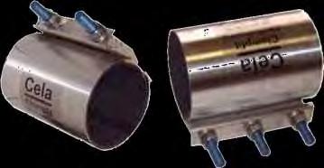


56 HDPE Components Repairs Electrofusion DI Compression


57 HDPE Components Yellow fittings are for gas mostly. Gas fittings do come in black too. Verify the ratings. Do not use these on irrigation systems unless you verify their ratings match what you need. Some gas fittings are medium density polyethylene, not all are HDPE and therefore not made for the high pressures.
58 HDPE Certification Socket Fusion


59 Molded Socket Fusion Fittings Sizes Available - up to 4 Tees Reducers 90 o Bends 45 o Bends Couplings Caps Standards ASTM 2683 AWWA C906 Resin 4710 DR DR11 Return policy All fittings are non-returnable


60 Molded Socket Fusion Fittings Sizes available ¾ to 4 Configurations Tees Reducers 90 o Bends 45 o Bends Couplings Caps Standards ASTM 2683 AWWA C906 Material resin 4710 DR DR11 Return policy All fittings are non-returnable
61 Molded Socket Fusion Fittings Tool preparation Extension cords and power source should be of suitable size for amperage draw of unit. R63 TXX unit draws a maximum of 800 watts. R125 QTE unit draws a maximum of 1,400 watts. Tool setup Tool faces consist of two parts, a male end for the interior socket surface and a female end for the exterior pipe surface. Insert the correct pipe/fitting inserts into the tool. Tighten bolt/nut to secure in place. Clean inserts to remove any dirt or debris before plugging into power source. Use 96% isopropyl alcohol pads or wipes. Acetone and a clean lint free rag or old tee shirt will work as well. Clean relatively cool, do not clean at 450 degrees


.")

62 Molded Socket Fusion Fittings Tool setup (continued) Allow machine to warm to proper temperature. R63 TFB Has a thermo regulator 495 to 500 degrees F. R63 TE Has an adjustment tab where you can increase or decrease temp. (preferred by someone who wants to weld more things than just HDPE or wants to get a higher temperature). Always check with a digital thermometer, do not ASSUME temp is correct. Acceptable fusing conditions No rain No dust No pollen Get out of winds if possible Tent the area if needed


63 Molded Socket Fusion Fittings Face the pipe Start with a clean straight cut of the pipe. Bevel the pipe edge with a chamfer tool. With chamfer tool in place, attach cold ring pliers. The chamfer tool acts as a depth gauge for how deep the pipe will insert into the fitting. The cold ring pliers act as a leverage point, a rounding tool to round the pipe, and as a marker for the depth when inserting the fitting on the pipe. Clean the pipe/fitting Use 96% isopropyl wipes or Acetone and a clean lint free rag or old tee shirt to remove any contaminants on the pipe and the inside edge of fitting.
64 Molded Socket Fusion Fittings Apply the heat Verify heating temperature is within the specified temperature range (490 o F 510 o F). Press both the pipe and fitting onto the tool for the heat time as shown on chart. This is given as a reference; your particular fittings manufacturer may require different heat times. Temperature and time cycles on chart are based on a 73 degrees Fahrenheit environment with no wind, rain or snow. Pipe Size (IPS inches) Heating Time (seconds) Cooling Time Seconds (minutes) Set Time Seconds (0.5 min) / (1.0 min) (1.0 min) (1.5 min) 30
65 Molded Socket Fusion Fittings Remove the tool Quickly pull the fitting off and the pipe out. The fitting will require more energy to remove from the tool. Try not to rotate pipe or fitting when removing from tool. Fuse the pipe/fitting Immediately and with equal and consistent pressure bring both pieces together quickly. DO NOT ROTATE THE PIPE when bringing together IF you do, you will need to cut the joint out and do it again.
66 Molded Socket Fusion Fittings Set time Hold the fitting, pipe, and cold ring clamp together for the required set time to keep the pipe and fitting from pushing apart. Once the set time is reached the pipe and fitting can be relaxed and the cold ring clamp can be removed. Pipe Size (IPS inches) Heating Time (seconds) Cooling Time Seconds (minutes) Set Time Seconds (0.5 min) / (1.0 min) (1.0 min) (1.5 min) 30
67 Molded Socket Fusion Fittings Cool time Refer to the chart below for time to allow fused joint to cool prior to movement. Inspect joint for quality. We recommend you allow the joint to cool an additional five (5) minutes before removing the cold ring and an additional ten (10) minutes of cooling before exposing the joint to any type of stresses (ie., burial or testing). Cleanup At the end of each day cool the unit and clean Teflon heating surface just like you did at the beginning. Pipe Size (IPS inches) Heating Time (seconds) Cooling Time Seconds (minutes) Set Time Seconds (0.5 min) / (1.0 min) (1.0 min) (1.5 min) 30
68 Why use Socket Fusion? Molded Socket Fusion Fittings Pro s Greater surface area fusion. Socket fusion tool is less expensive. Tool fits down into the work area where a butt fusion unit may not on a pulled or vibratory plowed job. Technique is somewhat forgiving to misalignment and debris; however fittings always need to be aligned and debris free regardless of procedure. Con s Extra cost to buy fittings you wouldn t need with butt fusion. Simple coupler requires two fusions. Could be considered a slower process. Need to use your muscles on 2 and larger to hold joint together by hand.
69 HDPE Certification Butt Fusion

 Fabricated")
70 IPS Butt Fusion Sizes available Up to 12 Configurations Tees 90 o Bends 45 o Bends Reducers Caps Standards Molded fittings ASTM D3261, AWWA C906 Resins 3408/3608, 4710 DR DR11 (can machine ends to pipe DR if required) Fabricated fittings


 Return")
71 IPS Molded Butt Fusion Fittings Sizes available Up to 12 Configurations Tees 90 o Bends 45 o Bends Reducers Caps Standards ASTM D3261 AWWA C905 Material resin 3408/ DR DR11 (can machine ends to pipe DR if required) Return policy All fittings are non-returnable
 45 o Bends (8-24 ) 22.")
72 IPS Fabricated Butt Fusion Fittings Sizes available 8 + Standards AWWA C906 Configurations Tees (10-24 ) Branch saddle reducing tees 90 o Bends (8-24 ) 45 o Bends (8-24 ) 22.5 o Bends (3-24 ) Material resin DR DR is made to match the pipe
73 Stress riser Stress riser is the additional stress loaded onto the fitting if the pipe and fitting are more than one DR apart from each other. This is eliminated by machining the fitting at the connection point to match the DR of the pipe. When ordering, you can specify what DR pipe they are intended for. IPS Fabricated Butt Fusion Fittings


74 IPS Fabricated Butt Fusion Fittings Fabricated fitting manufacturing RitmoAmerica Harrington Facility in Lynchburg Information provided courtesy of Harrington Corporation


75 IPS Butt Fusion Tool preparation Extension cords and power source should be of suitable size for amperage draw of unit. (Ram14 unit draws a maximum of 1,850 watts). Tool setup 1. Insert the correct pipe size inserts into the machine. 2. Plates hook into place from the one end and then retaining screw is tightened on the other end. Clean inserts to remove any dirt or debris before plugging into power source. 96% isopropyl alcohol pads or wipes should be used Acetone and a clean lint free rag or old tee shirt will work as well. Clean relatively cool, do not clean at 450 degrees.
76 IPS Butt Fusion Clean the pipe/fitting Clean pipe ends to remove any dirt or debris. 96% isopropyl alcohol pads or wipes Acetone and a clean lint free rag or old tee shirt will work as well. Clean relatively cool, do not clean at 450 degrees. Acceptable fusing conditions No rain No dust No pollen Get out of winds if possible Tent the area if needed


77 IPS Butt Fusion Clamp pipe Clamp pipe ends in fusion machine. Check alignment and apply fusion pressure with handles to check for slippage. Cut the pipe any way you want as long as you don t use heat (like a torch). Object is to bring the pipe to come into the machine flush, so try and do a straight cut. Support the pipe on either side of the machine; tip the machine toward the pipe to clamp it in the machine. Make sure grips are tight enough to handle the force when you pull both pieces together.

78 IPS Butt Fusion Face the pipe/fitting Face the edges to establish smooth, clean, parallel mating surfaces. Face pipe halfway to stops, check alignment and adjust if needed, then face to the stops. You don t want to be taking off too much material as this wastes time and material. Need to do at least ½ of facing on both sides to be sure it is straight and true. Complete facing produces continuous circumferential shavings from both ends. Remove the facing tool, and clear all shavings and pipe chips from the component ends. Do not touch the component ends with your hands after facing.
79 IPS Butt Fusion Apply the heat Use the set buttons to increase temperature. 450 degrees is target, acceptable range is 435 to 465 degree window. Keep plate out of the wind in the sack to get it to temperature. Verify proper heat-plate temperature with thermometer. Insert heat-plate between pipe ends and initiate contact with heat- plate. Maintain this contact during heating time, but do not apply pressure. Ratchet the handle against to hold it. Pipe Size (IPS inches) Heating Time (seconds) Cooling Time Seconds (minutes) Approximate Melt Bead Size (inches) (1.5 min) 1/16 1-1/ (1.5 min) 1/ (1.5 min) 1/ (3 min) 1/ (3.65 min) 1/8

 Heating Time (seconds) Cooling Time Seconds (minutes) Approximate Melt Bead Size (inches) 1 16-20 90 (1.")
80 IPS Butt Fusion Apply the heat Watch for the proper bead size regardless of the heat time! Too much pressure will restrict flow. Too little pressure will create a weak joint. If the melt bead curls significantly away from the heating tool surface, unacceptable pressure during heating may have occurred and the joint should be redone. Pipe Size (IPS inches) Heating Time (seconds) Cooling Time Seconds (minutes) Approximate Melt Bead Size (inches) (1.5 min) 1/16 1-1/ (1.5 min) 1/ (1.5 min) 1/ (3 min) 1/ (3.65 min) 1/8
81 IPS Butt Fusion Fuse the joint After proper melt bead size is formed, remove heat-plate. Immediately after the heating tool is removed, quickly inspect the melted ends, which should be flat, smooth and completely melted. If the melt surfaces are acceptable, immediately and in a continuous motion, bring the ends together and apply the correct joining force (or fusion pressure). The correct fusion pressure will form a double bead that is rolled over to the surface on both ends. Be careful not to slam the pipe ends together.
82 IPS Butt Fusion Cool time Hold joining force against the ends until the joint is cool. The joint is cool enough for gentle handling when the double bead is cool to the touch. Cool for about seconds per inch of pipe diameter. Do not try to decrease the cooling time by applying water, wet cloths or the like. Avoid pulling, pressure testing, and rough handling for at least an additional 30 minutes. Heavier wall thickness pipes require longer cooling times. Pipe Size (IPS inches) Heating Time (seconds) Cooling Time Seconds (minutes) Approximate Melt Bead Size (inches) (1.5 min) 1/16 1-1/ (1.5 min) 1/ (1.5 min) 1/ (3 min) 1/ (3.65 min) 1/8
83 IPS Butt Fusion Cool time Hold joining force against the ends until the joint is cool. The joint is cool enough for gentle handling when the double bead is cool to the touch. Cool for about seconds per inch of pipe diameter. Do not try to decrease the cooling time by applying water, wet cloths or the like. Avoid pulling, pressure testing, and rough handling for at least an additional 30 minutes. Heavier wall thickness pipes require longer cooling times. Pipe Size (IPS inches) Heating Time (seconds) Cooling Time Seconds (minutes) Approximate Melt Bead Size (inches) (1.5 min) 1/16 1-1/ (1.5 min) 1/ (1.5 min) 1/ (3 min) 1/ (3.65 min) 1/8
84 IPS Butt Fusion Approximate Melt Bead Size Pipe Size (OD) Approximate Melt Bead Size* 1 1/4" and smaller 1/32" - 1/8" 1 1/4" - 3" About 1/16" 3" - 8" 1/8" - 9/16" 8" - 12" 3/16" - 1/4" 12" - 24" 1/4" - 7/16" 24" - 36" About 7/16" 36" - 65" About 9/16" *The appearance of the melt swell zone may vary depending on the pipe material. The melt bead width is to be determined by measuring the distance from the heater plate to the melt swell origin.


85 IPS Sidewall Butt Fusion Fusion Saddles Sidewall branch saddle Sidewall tapping saddle
86 HDPE Certification Electrofusion - Fittings


87 Molded Electrofusion Fittings Sizes Available Up to 28 Material resin 4710 Configurations Couplings Saddles 90 o Bends Tees Standards ASTM F1055 AWWA C906 DR DR11 Return policy All fittings are bagged, if bag has been opened or compromised, the fitting is non-returnable


88 Molded Electrofusion Fittings Tool preparation Extension cords and power source should be of suitable size for amperage draw of unit. Marking Pen Sharpie metallic silver or Sharpie paint No less than 96% Isopropyl Alcohol Clean, white, lint free cloths. Small mirror for examining under side of pipe Flashlight Paper (business card) Pipe scraper Vacuum
89 Molded Electrofusion Fittings Clean the pipe and/or fitting Mark the fusing area with a wax crayon or marker. Scrape the pipe surface carefully using an approved scraper. Remove contaminated surface caused by UV and weather Use a small mirror when scraping pipe in trench to see if the bottom of pipe is scraped completely. After scraping, remove dirt and grease from the welding area of the pipe and the inside of the fitting using an approved cleaning agent (no less than 96% isopropyl alcohol) and clean, white, lint free cloths. Remove fitting from protective packaging. Inspect and clean fusion surface of fitting with approved cleaning agent. Be sure both surfaces of fitting and pipe are completely dry. The pipe and assembly can not be under load of any kind. Secure the pipe before and after the fitting so it won t move till fused. Use clamps and braces if necessary


90 Molded Electrofusion Fittings Clean the pipe and/or fitting For large pipe diameters, significant time can be saved using a rotary pipe scraper.
 on the pipe being careful not to contaminate the previously")


91 Molded Electrofusion Fittings Assemble Immediately after surfaces have dried put the fitting(s) on the pipe being careful not to contaminate the previously cleaned surfaces. Tighten up any braces being used to secure pipe from moving. Inspect the interface between the fitting surface and the pipe surface. The gap between the two surfaces should not be able to pass the thickness of a sheet of paper ½ wide to no more than a depth of ¾. Said another way no more than a gap gauge 1-2 MM. It may be necessary to allow time for the pipe and fitting to conform to each other. Do not attempt fusion unless this requirement is met.
92 Molded Electrofusion Fittings Assemble and fuse Connect the two electric pins to the fusion connectors of the Electrofusion fitting. Scan the bar code with the optical pen or enter the welding parameters manually. After completing the welding process verify that no material has leaked out of the joint between the pipe and the fitting. The fusion machine should alert you if the fitting is bad or if there is not sufficient power to make the fuse.

93 Molded Electrofusion Fittings Cool and inspect Allow a cooling time as noted on fitting, or until the saddle is not too hot to touch. Do not apply system loads or pressures until the fitting and pipe are completely cooled. Use a flashlight and inspect all edges of the fitting to verify that no material has leaked out of the joint between the pipe and the fitting. If something went wrong, there is no way to repair what you have done. It will need to be cut out and completely re-done. Better to take the time and do it right the first time!
94 HDPE Certification Electrofusion - Saddles


95 Molded Electrofusion Fittings Scrape and clean with alcohol Attach saddle Drill hole and remove debris Install angle valve Attach cables and fuse saddle

 Pipe")
96 Molded Electrofusion Saddles Tool preparation Extension cords and power source should be of suitable size for amperage draw of unit. Marking pen Sharpie metallic silver or Sharpie paint No less than 96% isopropyl alcohol Clean, white, lint free cloths Flashlight Timer Paper (Business Card) Pipe Scraper Shop vac Cordless Drill and hole saw

97 Molded Electrofusion Saddles Clean the pipe and/or fitting Hold the saddle against the pipe and mark the welding area with a wax crayon or marker. Scrape the pipe surface carefully using an approved scraper. Remove contaminated surface caused by UV and weather After scraping remove dirt and grease from the welding area of the pipe and the inside of the saddle using an approved cleaning agent (no less than 96% isopropyl alcohol) and clean, white, lint free cloths. Remove saddle from protective packaging. Inspect and clean fusion surface of saddle with approved cleaning agent. Be sure both surfaces of fitting and saddle are completely dry. Secure the pipe in some way so it won t move till fused.
98 Molded Electrofusion Saddles Assemble Immediately after surfaces have dried put the saddle on the pipe being careful not to contaminate the previously cleaned surfaces. Use a wrench to tighten the four nuts concurrently until the strap and the saddle meet for pipe sizes up to and including 12 in diameter. For sizes 14 and above use a top loading tool. Tighten up any braces being used to secure pipe from moving. Inspect the interface between the fitting surface and the pipe surface. The gap between the two surfaces should not be able to pass the thickness of a sheet of paper ½ wide to no more than a depth of ¾. It may be necessary to allow time for the pipe and fitting to conform to each other. Do not attempt fusion unless this requirement is met. You may want to have some clamps on hand to help re-shape pipe if needed. Scrape and clean with alcohol clean with alcohol Attach saddle


99 Molded Electrofusion Saddles Assemble Top loading tools are used as clamping tools to exert pressure on the saddle from above while supporting the pipe underneath. For pipe sizes 14 in diameter and above always use a top loading tool. Top loading tools
100 Molded Electrofusion Saddles Assemble & Fuse Connect the two electric pins to the fusion connectors of the Electrofusion saddle. Scan the bar code with the optical pen or enter the welding parameters manually. After completing the welding process verify that no material has leaked out of the joint between the pipe and the saddle. The fusion machine should alert you if the fitting is bad or if there is not sufficient power to make the fuse. Attach cables and fuse saddle
101 Molded Electrofusion Saddles Cool and inspect Allow a cooling time as noted on fitting, or until the saddle is not too hot to touch. Do not apply system loads or pressures until the fitting and pipe are completely cooled. Use a flashlight and inspect all edges of the fitting to verify that no material has leaked out of the joint between the pipe and the fitting. If something went wrong, there is no way to repair what you have done. It will need to be cut out and completely re-done. Allow fitting to cool Better to take the time and do it right the first time!
102 Molded Electrofusion Saddles Tap the hole Proceed now with the tapping of the pipe using the hole saw. Be very careful not to drill through the bottom of the pipe. Use a vacuum to remove drill shavings. Small PVC pipe length reduced up to vacuum hose size works well. Saddle straps may be removed or left in place. Drill hole and remove debris
103 HDPE Certification Compression Fittings


104 Compression Fittings Available sizes 1/2-2 Configurations Tees 90s Couplers Reducing Couplers Male Adapters Female Adapters Features 230 psi rated Corrosion resistant Benefits Built in restraints No special equipment Application Repair Maintenance Additions


105 HDPE Compression Most common compression service tee Acme thread Harco service fitting PN x 2 x 1-1/2 Acme Thread Outlet


106 HDPE Compression

107 HDPE Compression
108 HDPE Certification Flange Adapters

109 Flange Adapters & Backup Rings Sizes available 2-24 Standards HDPE flange adapter-astm D2683 Back up ring- NONE Materials HDPE Back up ring- Ductile Iron


110 Flange Adapters & Backup Rings Sizes available 2-24 Standards HDPE flange adapter-astm D2683 Back up ring- NONE Materials HDPE Back up ring- Ductile Iron

111 Flange Adapters & Backup Rings Sizes available 2-24 Standards HDPE flange adapter-astm D2683 Back up ring- NONE Materials HDPE Back up ring- Ductile Iron
112 HDPE Certification Valves

113 HDPE Components Valves HDPE PVC Union SloClose Ball Valve Flange & MJ DI Push On DI Saddle/Angel valve DI with HDPE Stubs


114 Valves HDPE Ball Valves Traditionally thought of in the use of HDPE. Check ratings, make sure it is for use with water. Nordstrom Integrifuse

115 Valves Flanged DI Gate Valve Nibco, AVK, Kennedy, Clow Resilient wedge


116 Valves Mechanical Joint DI Gate Valve Nibco, AVK, Kennedy, Clow Resilient wedge


117 Valves DI Push-On Gate Valve w/external Joint restraint Any Push-On valve can be used with stainless stiffeners and external joint restraints.


118 Valves DI Gate Valves with HDPE Stubs Harco/AVK Series 66 Valve HDPE ends 2 DI lug valve with resilient wedge 2 14 sizes available for HDPE pipe. AWWA C-515 standards, rated for up to 250 psi applications. Stocked in Lynchburg, VA
119 Valves Lasco/Colonial SloClose Ball Valve 2 3 sizes in HDPE Full port valve One complete turn valve Unions incorporated into valve Various configurations HDPE x HDPE HDPE x Glue HDPE x FIPT Needs an elbow after valve for HDPE straight runs more than 24 This is a directional valve Arrow on side indicates flow direction.


120 Valves Harco lateral valve on HDPE saddle Pipe end tapered prior to inserting Stiffener loaded in end of pipe Cold ring pliers clamped on for leverage and as depth gauge for complete insertion.


121 Valves Leemco lateral valve on HDPE saddle Pipe end tapered prior to inserting Stiffener loaded in end of pipe Cold ring pliers clamped on for leverage and as depth gauge for complete insertion.
122 HDPE Certification Mechanical Saddles


123 HDPE Saddles Most common mechanical saddle Acme thread FIPT thread Solvent (slip) 1.5 to 3 Manufacturer s installation recommendation shown: Lasco - Saddle PN x 1-1/2 Acme Thread Outlet HDPE pipe is not always round like PVC, it could be oval. To compensate for that the instructions state Allow 2 hours for the piping material to yield or round properly. Stage two requires retightening the bolts Use cold ring clamps during installation to eliminates the come back.


124 HDPE Saddles Most common mechanical saddle Acme thread FIPT thread Solvent (slip) 1.5 to 3 Best practice is to use a P series swing joint and install the saddle opening vertically on the pipe. Mechanical saddles are used simply because of the cost issue. If we remove cost from the equation then fusion saddles would become the most common.
125 HDPE Certification Transitions


126 Transitions Sizes available Up to 4 Configurations HDPE Butt x Thread HDPE Butt x Spigot w/ stiffener HDPE Butt x 1.5 Acme FIPT Standards NONE Material resin DR DR11 Available in brass, 304 SS and 316 SS

127 Pipe Stiffeners Sizes available Material 304SS DR Stiffener manufactured to specific pipe DR


128 Flange & MJ Adapters Sizes available 2-24 Standards HDPE Flange Adapter-ASTM D2683 Back up ring - NONE Materials HDPE Back up ring - Ductile Iron

129 PVC to HDPE Adapters PVC to HDPE Transition Joint restraint x DI Fittings x Joint restraint with HDPE stiffener (inside pipe)


130 PVC to HDPE Transition Philmac Compression fitting HDPE x PVC Available in 2 only PVC to HDPE Adapters
131 HDPE Certification Commercial Applications

132 Butt Fusion connections Mainline and laterals Commercial application Compression connections Sprinkler heads

133 Compression connections Mainline and laterals Commercial application Compression connections Sprinkler heads

134 Compression connections Mainline and laterals Commercial application Compression connections Sprinkler heads
PVC FASTTAP SADDLES for IPS Mains. Main Size OUTLET 1 FPT 3/4 CTS (7/8 OD) COMPRESSION 1 CTS (1 1/8 OD) COMPRESSION 3/4 IPS COMPRESSION
 COMPRESSION 1 CTS (1 1/8 OD) COMPRESSION 3/4 IPS COMPRESSION") PVC FASTTAP SADDLES PVC FASTTAP SADDLES for IPS Mains THE ULTIMATE CONNECTION OUTLET 3/4 IPS FEMALE SLIP OR 1 IPS MALE SLIP SOLVENT WELD 1 IPS FEMALE SLIP SOLVENT WELD 3/4 MPT 1 MPT 3/4 FPT MAIN 13/16
PVC FASTTAP SADDLES PVC FASTTAP SADDLES for IPS Mains THE ULTIMATE CONNECTION OUTLET 3/4 IPS FEMALE SLIP OR 1 IPS MALE SLIP SOLVENT WELD 1 IPS FEMALE SLIP SOLVENT WELD 3/4 MPT 1 MPT 3/4 FPT MAIN 13/16
IAPMO GUIDE CRITERIA FOR BALL VALVES IAPMO IGC PURPOSE
 INTERNATIONAL ASSOCIATION OF PLUMBING AND MECHANICAL OFFICIALS IAPMO GUIDE CRITERIA FOR BALL VALVES IAPMO IGC 157-20067 1 PURPOSE 1.1 The purpose of this standard is to establish an acceptable standard
Instruction Manual. PE-25/32/37 Tapping Machines. POLYTAPP Valves
 Instruction Manual PE-25/32/37 Tapping Machines & POLYTAPP Valves Nov 2016, Revision 2 Document Number 3000111 2 M.T. Deason Company, Inc. PO Box 101807 Birmingham, AL 35210 Phone: 205 956 2266 Fax: 205
Quality Plastic Pipe Fittings. Technical Data. Fabricated PVC Fittings IPS Class 100, 125, 160, 200 SCH 40 & SCH 80 Solvent Weld & Gasketed
 Quality Plastic Pipe Fittings Technical Data Fabricated PVC Fittings IPS Class 100, 125, 160, 200 SCH 40 & SCH 80 Solvent Weld & Gasketed Effective April 1, 2002 PIPE DIMENSIONS IPS-IRON PIPE SIZE Minimum
Continental Industries TRANSITION FITTINGS or FAX Visit
 Continental Industries TRANSITION FITTINGS 1-800-558-1373 or FAX 1-800-788-1668 Visit www.conind.com ABOUT US Our Company Continental Industries, headquartered in Tulsa, Oklahoma, was formed in 1958 and
GAS DISTRIBUTION PRODUCTS TRANSITION FITTINGS
 GAS DISTRIBUTION PRODUCTS TRANSITION FITTINGS CONTINENTAL INDUSTRIES, INC. The Ultimate Connection CONTINENTAL INDUSTRIES, INC. ABOUT US THE ULTIMATE CONNECTION Our Company Continental Industries, Inc.,
Continental Industries STEEL SERVICE TEES or FAX Visit
 Continental Industries STEEL SERVICE TEES 1-800-558-1373 or FAX 1-800-788-1668 Visit www.conind.com ABOUT US Our Company Continental Industries, headquartered in Tulsa, Oklahoma, was formed in 1958 and
MUELLER. Mega-Lite Drilling Machine. Reliable Connections. table of contents PAGE. Equipment 2. Operating Instructions 3-4. Parts Information 5
 operating Instructions manual MUELLER Mega-Lite Drilling Machine table of contents PAGE Equipment 2 Operating Instructions 3-4 Parts Information 5 Travel Charts 6-11! WARNING: 1. Read and follow instructions
Team Insert Valve Sample Specification The Insert Valve shall conform to the following:
 Team Insert Valve Sample Specification The Insert Valve shall conform to the following: The Ductile Iron 250 p.s.i.g. Insert Valve shall be a Resilient Wedge Gate Valve designed for use in potable water,
PE 2708 CTS & IPS GAS PIPE
 Specifications: Resin Chevron Phillips TR418Q PE 2708 Resin formulation listed in PPI TR4 Hydrostatic Design Basis: 1250 psi @ 73 F, 800 psi @ 140 F Cell Classification per ASTM D3350 = 234373E or 234375E
Operating Procedures for GripTight 15.5 SDR & IPS Test Plugs
 EST Group DC2518 08/01 REV 3 12/12 Page 1 of 6 Operating Procedures for GripTight SDR & IPS Test Plugs WARNING For proper operation, GripTight plugs must be assembled as shown in Figure 1. Pressure testing
pvc well casing & drop pipe
 C e r t a i nte e d pvc well casing & drop pipe P V C We l l P r o d u c t s Sure Fit PVC well casing and drop pipe have gained broad acceptance since their introduction almost 40 years ago. Today, due
Flexible Metal Hose Products
 Flexible Metal Hose Products Specialty Flexible Hose Solutions of Stainless Steel The AEROCOM Advantage Aerocom offers engineered solutions that address specific flexible piping challenges such as vibration,
PSI Mechanical Couplings
 Pipeline Accessories PSI Mechanical Couplings Systems Permasert and PermaLock Permasert and Permalock are Elster Perfection registered trade marks General Information Technical Data Installation Instructions
SECTION BUTTERFLY VALVES
 SECTION 15112 BUTTERFLY VALVES PART 1 GENERAL 1.01 SUMMARY A. All butterfly valves shall be of the tight closing, rubber seated type and fully comply with the latest revision of AWWA Standard C504, Class
MUELLER. A Wall Type. Indicator Post. Reliable Connections. General Information 2. Technical Data/ Dimensions 3. Installation 4-5.
 Installation Instructions manual MUELLER table of contents PAGE A-20814 Wall Type General Information 2 Technical Data/ Dimensions Installation 4-5 Maintenance 6 Parts 7 Indicator Post! WARNING: 1. Read
APG001. Application Guide for Gas. T: F: E:
 APG001 Application Guide for Gas T: 01480 442600 F: 01480 458829 E: customerservice@gpsuk.com www.gpsuk.com Application Guide for Gas Introduction 3-4 Range Overview 5-6 PE80 Yellow Pipe 7-9 Excel Yellow
Ford Service Saddles and Tapping Sleeves
 Section AA 5/2001 Ford Service Saddles and Tapping Sleeves The Ford Meter Box Co., Inc. 775 Manchester Avenue, P.O. Box 443, Wabash, Indiana, USA 46992-0443 Telephone: 219/563-3171 FAX: 1-800-826-3487
Halsey Taylor Owners Manual STOP!
 Halsey Taylor Owners Manual 4710 Freeze Resistant Floor Mounted Steel Fountain STOP! PLEASE READ THE FOLLOWING INFORMATION. ITALLATION ITRUCTIO FOR THE 4710FR FTN. WITH 97243C SINGLE VALVE CONTROL ASSEMBLY
-Proline Polypropylene Single Wall Piping
 EFFECTIVE: 6/01/11 Industrial Piping Systems Dimensional Guide #PDIM Proline Super Proline Single Chemical Wall Grade Piping PVDF System -Proline Single Wall Piping s 3 r z s www.asahi-america.com Dimensions
FUSAMATIC MULTISEAL TAPPING TEE STACKLOAD OR UNDERCLAMP FOR GAS AND WATER....Connect
 FUSAMATIC MULTISEAL TAPPING TEE STACKLOAD OR UNDERCLAMP FOR GAS AND WATER...Connect FUSAMATIC MULTISEAL TAPPING TEE FOR GAS AND WATER Fusion Group Limited pioneered polyethylene pipe jointing in the UK
Section GATE VALVES
 Section 02521 PART 1 GENERAL 1.01 SUMMARY This Section includes the furnishing and installation of gate valves for isolation and dead-end service as shown on Plans and as specified herein. 1.02 MEASUREMENT
Hot Tapping Machine. OPERATIONS MANUAL and OPERATING INSTRUCTIONS
 262-2040 Hot Tapping Machine For performing 1/4 6 Hot taps 285 psi or less. Municipal Water, Sewage, & Building Services Use OPERATIONS MANUAL and OPERATING INSTRUCTIONS WARNING: These instructions are
INSERT PRESSURE FITTINGS PRODUCTS PRICE LIST PRICE GROUP DISCOUNT MULTIPLIER DESCRIPTION 05 PVC INSERT FITTINGS
 PRICE GROUP DESCRIPTION 05 PVC INSERT FITTINGS DISCOUNT MULTIPLIER Phone: (315) 451-1100 or (800) 776-2266 Fax: (800) 729-3299 7652 Morgan Road Liverpool, New York 13090 PRODUCTS INSERT PRESSURE FITTINGS
The X-11 Molding Chamber
 The User Guide to The X-11 Molding Chamber Table of Contents Overview of Features & Specifications... 3 Features... 4-5 Safety & Maintenance... 6 Initial Startup Procedure... 7 Using the X-11... 8-9 Using
Gas Lines. Technical Manual. Sumitomo (SHI) Cryogenics of America, Inc Vultee Street Allentown, PA U.S.A.
 Cryogenics of America, Inc Vultee Street Allentown, PA U.S.A.") Gas Lines Technical Manual Sumitomo (SHI) Cryogenics of America, Inc. 1833 Vultee Street Allentown, PA 18103-4783 U.S.A. Revision F: April 2008 261320A TABLE OF CONTENTS Page DESCRIPTION...1 SPECIFICATIONS...2
Gas Lines Technical Manual Sumitomo (SHI) Cryogenics of America, Inc. 1833 Vultee Street Allentown, PA 18103-4783 U.S.A. Revision F: April 2008 261320A TABLE OF CONTENTS Page DESCRIPTION...1 SPECIFICATIONS...2
INFACT CORPORATION WATERWORKS PRODUCTS FLEX T-2 SPECIFICATION S TOLL FREE:
 CORPORATION WATERWORKS PRODUCTS T-2 SPECIFICATION S TOLL FREE: 888-773-9130 email: info@infactcorp.com www.infactcorp.com T-2 Valve and Fitting Restraint Lower total installed cost No couplings, no pipe
INSERT FITTINGS INSERT FITTINGS
 Insert Tee Insert x Female Tee Insert Elbow Insert x Male Elbow Insert Coupling Insert x Male Adapter Insert x Female Adapter Insert Plug POLY and NYLON FITTINGS For use with Poly Tubing Fitting 1/2 3/4
Halsey Taylor Owners Manual 4410 Freeze Resistant Tubular Fountain STOP!
 Halsey Taylor Owners Manual 4410 Freeze Resistant Tubular Fountain STOP! PLEASE READ THE FOLLOWING INFORMATION. ITALLATION ITRUCTIO FOR THE 4410FR FTN. WITH 97243C SINGLE VALVE CONTROL ASSEMBLY ARE LOCATED
MUELLER. A A Adjustable. Vertical Indicator Posts. Reliable Connections. General Information 2. Technical Data 3.
 Installation Instructions manual MUELLER table of contents PAGE A-20806 A-20807 Adjustable General Information 2 Technical Data 3 Dimensions 4 Installation 5-6 Parts 7 Maintenance 8 Vertical Indicator
REFER TO AQUATHERM TECHNICAL BULLETIN A-AQTTB FOR ADDITIONAL INFORMATION AND SAFETY PRECAUTIONS
 Aquatherm Standard Pressure Testing Procedure Aquatherm offers an extensive warranty to protect against damages caused by failure from manufacturer s defect. Aquatherm requires that all installations be
Ecoflex pre-insulated pipe energy efficiency made easy
 E c o f l e x C o m p l e t e Catalog Supplement June 2010 Hydronic heating, cooling and potable-water distribution Fast, easy installations Energy-efficient Flexible, durable Custom-cut, long lengths
Engineering Data Sheet
 Page 1 of 6 CE MARKING AND THE PRESSURE EQUIPMENT DIRECTIVE 97/23/EC Valves must be installed into a well designed system and it is recommended that the system be inspected in accordance with the appropriate
Simple to install connection fails. The Talbot Pushfit fitting is pressure rated PN 16.
 Talbot Pushfit Talbot Pushfit - Fittings for Water Pipe Talbot Grippa Universal Service Connector The Talbot Pushfit connection is a tried and tested method of connecting low, The Talbot Grippa is a universal
Installation and Maintenance Manual. Compact Medical Gas Outlets
 Installation and Maintenance Manual Compact Medical Gas Outlets Contents Product Description 3 Cleaning and Lubricating 4 Inspection and Testing 4 Installation and Dimensions 5-6 Compact Outlet Indexing
World Area Differences Technical Information
 World Area Differences Technical Information DMISC2047X02 This document is to give more information about the following: Porting & Threads Cleaning Procedures Conversion Tables PORTING & THREADS NPT (National
SIMPLAIR PIPING TOOL. JXT Company
 SIMPLAIR PIPING INGERSOLL-RAND SIMPLAIR PIPING With push-in fittings and lightweight anodized aluminum pipe, a SimplAir system provides ideal connection throughout your entire air distribution system.
CPVC Transition Fittings - Female Adapter. CPVC X LEAD FREE BRASS Lead Free Max working pressure F ASTM D 2846
 CPVC Transition Fittings - Female Adapter STD4703BTLF12 1/2 CPVC X 1/2 FIP 25 250 CPVC Transition Fittings - Female Adapter STD4703BTLF34 3/4 CPVC X 3/4 FIP 25 250 CPVC Transition Fittings - Female Adapter
PN LINE. Technical remarks PN 11 PN 13 PN 14 PN 15 PN 17 PN 18 PN 20 PN 23 PN 25 PN 26 PN 27 PN 28 PN 29 PN 37 PN 38 PN 39 PN 40 PN 43 PN 10 8_9 10_12
 PN LINE PN 11 PN 13 PN 14 PN 15 PN 17 PN 18 PN 20 PN 23 PN 25 PN 26 PN 27 PN 28 PN 29 PN 37 PN 38 PN 39 PN 40 PN 43 PN 10 Technical remarks PN 11 PN 13 PN 14 PN 15 PN 17 PN 18 PN 20 PN 23 PN 25 PN 26 PN
INSTALLATION INSTRUCTIONS FOR GRT75-PF-RFS PET FOUNTAIN
 INSTALLATION INSTRUCTIONS FOR GRT75-PF-RFS PET FOUNTAIN Important: Read all instructions and refer to local codes prior to installation. l Local soil conditions may require more gravel for drainage. l
Job or Customer: Engineer: Contractor: Submitted by: Approved by: Order No: Specification:
 Submittal Data Sheet Job or Customer: Engineer: Contractor: Submitted by: Approved by: Order No: Specification: Date Date Date introduction IPEX s Encase electrofusion-joint system is the preferred solution
PRODUCT CATALOGUE 2010
 PRODUCT CATALOGUE 2010 Page 2 TABLE OF CONTENTS PRODUCT LINE DESCRIPTION PAGE NO. COMPANY PROFILE Brief Company History, NEXOR, About Us, Mission 3 1 2 3 4 5 NEXOR HDPE Pressure Mains Pipe For Potable
Standard and Low-Flow Metric Powder Feed Pumps
 Instruction Sheet P/N 06699E Standard and Low-Flow Metric Powder Feed Pumps Introduction Standard and low-flow metric powder feed pumps are used to deliver organic and metallic powder coatings to powder
MUELLER A A Non-Adjustable. Vertical Indicator Posts. Reliable Connections. General Information 2. Technical Data 3.
 Installation Instructions manual MUELLER table of contents PAGE A-20808 General Information 2 Technical Data 3 Dimensions 4 A-20809 Non-Adjustable Installation 5-6 Parts 7 Maintenance 8 Vertical Indicator
Casing Spacer Technology Leaders
 Casing Spacer Technology Leaders Benefit today. Save down the line. www.racispacers.com NORTH AMERICA Why Raci Raci has been the global leader in casing spacer technology since 1952. Our uniquely designed,
APPROVED MANUFACTURERS PRODUCTS FOR WATER SYSTEMS 2017 PRODUCT SPECIFICATIONS MANUFACTURER DESCRIPTION/MODEL CASING. Power Seal
 CASING Stainless Steel Body Advance Products & SI or SSI SPACERS Systems / Model 4810 COUPLINGS Watermain Pipe Epoxy Coated Krausz HyMax (AC Pipe) HyMax Grip (PVC/Steel) Ductile Iron / Model 3501 AWWA
Mild steel. Stainless steel. HPR130XD Auto Gas Revision 2. Nozzle retaining cap. tube. Shield cap 30 A 50 A 80 A 130 A
 Operation Mild steel cap Nozzle retaining cap Nozzle Swirl ring Electrode 220194 220754 220193 220180 220192 220555 220754 220554 220553 220552 Water tube 30 A 50 A 220340 220747 80 A 220189 220756 220188
Vertical and Horizontal Bladder Tanks
 DATA SHEET Vertical and Horizontal Tanks Application The ANSUL bladder tank is one component in a balanced pressure proportioning system. Its operation requires no external power other than a pressurized
Valves. Controllers. Valves Two Types
 Hydraulics Taking the Irritation out of Irrigation My plants are getting irrigated, so I m all set, right? Marcus Duck Academic Advisor, Instructor & Program Coordinator MSU s 2-year Horticulture Programs
FITTING IDENTIFICATION AMERICANT THREAD TYPES APPENDIX ALFAGOMMA // APPENDIX. Dash numers. NPTF (National Pipe Tapered Fuel)
") // FITTINGS GUIDelines FITTING IDENTIFICATION numers Most fluid piping system sizes are measured by dash numbers. These are universally used abbreviations for the size of component expressed as the numerator
// FITTINGS GUIDelines FITTING IDENTIFICATION numers Most fluid piping system sizes are measured by dash numbers. These are universally used abbreviations for the size of component expressed as the numerator
Horizontal Bladder Tanks
 DATA SHEET Horizontal Bladder Tanks Features UL Listed and FM Approved for use with various ANSUL proportioners and foam concentrates 175 psi (12.1 bar) maximum allowable working pressure (design pressure)
Flange Bolt Torquing. for Resistoflex Plastic-Lined Piping Products. Torquing. Retorquing. Hydrotesting. Annual retorquing
 Flange Bolt Torquing for Resistoflex Plastic-Lined Piping Products Torquing When assembling flange connections, always use a full complement of clean, new high strength A193-B7 bolting. If using stainless
DVS Technical - Codes and Bulletins. Table of Contents
 DVS 1904-1 (2010-02) Adhesive bonding of plastic in domestic installation Requirements on plants and personnel. 1 DVS 1904-2 (2010-02) Adhesive bonding of plastics in domestic installation Pipes and fittings
AWWA C504 COMPLIANT VALVES FROM 3 THRU 108
 AWWA C504 COMPLIANT VALVES FROM 3 THRU 108 PO Box 411 Berwick PA 18603 800-247-VALV www.crispinvalve.com 500 SERIES: Sizes 3-20 Available The K-Flo 500 Series is a heavy-duty resilient seated butterfly
DVS Technical Codes an Bulletins
 DVS Technical Codes an Bulletins DVS 1904-1 (2010-02) Adhesive bonding of plastics in domestic installation Requirements on plants and personnel... 1 DVS 1904-2 (2010-02) Adhesive bonding of plastics in
INSTALLATION, OPERATION AND MAINTENANCE GUIDE
 INSTALLATION, OPERATION AND Placement in Pipeline System When installing Process Development & Control s ElastoTITE Elastomer-Hinged Check Valves in a pipeline, a minimum of five pipe diameters should
Installation, Operation and Maintenance Manual for Back Pressure Regulator
 Installation, Operation and Maintenance Manual for Back Pressure Regulator Model 8860 2009 Groth Corporation IOM-8860 Rev. B 12541 Ref. ID: 95565 Page 2 of 13 Table of Contents I. INTRODUCTION 3 II. DESIGN
LARGE R/W GATE VALVES
 The original, and the definitive standard. LARGE R/W GATE VALVES 24 THROUGH 54 STYLE 7000 AWWA C515 250 PSI NSF 61 Certified Fusion Bond Epoxy Coated 10 Year Limited Warranty M&H Valve is a division of
Arctic Insulation & Manufacturing The Pre-Insulated Pipe People
 Arctic Insulation & Manufacturing The Pre-Insulated Pipe People Butt Fusion Process for McElroy Mid-Range Hydraulic Operated Equipment No. 28/250 Class Machine 2 IPS 8 DIPS No. 412/618 Class Machine 4
Tech. Services: (800) Fax: (800) Order Entry: (800) Fax: (800) MODEL D INFLATABLE JACKS
 Fax: (800) Order Entry: (800) Fax: (800) MODEL D INFLATABLE JACKS") SPX Corporation 5885 11th Street Rockford, IL 6119-3699 USA Internet Address: http://www.powerteam.com Tech. Services: (8) 477-8326 Fax: (8) 765-8326 Order Entry: (8) 541-1418 Fax: (8) 288-731 Parts List
SPX Corporation 5885 11th Street Rockford, IL 6119-3699 USA Internet Address: http://www.powerteam.com Tech. Services: (8) 477-8326 Fax: (8) 765-8326 Order Entry: (8) 541-1418 Fax: (8) 288-731 Parts List
// ADapters GUIDelines
 // ADapters GUIDelines ADAPTER SELECTION Selection of an appropriate ALFAGOMMA adapter for a given application depends on the fluid system operating parameters listed below and the tube material and wall
1 DRIVE INDUSTRIAL IMPACT WRENCH
 1 DRIVE INDUSTRIAL IMPACT WRENCH 92622 ASSEMBLY AND OPERATING INSTRUCTIONS 3491 Mission Oaks Blvd., Camarillo, CA 93011 Visit our Web site at http://www.harborfreight.com Copyright 2004 by Harbor Freight
SUMMITTM 400 & 600. Natural Gas Barbecues. Step-By-Step Guide
 SUMMITTM 400 & 600 Natural Gas Barbecues Step-By-Step Guide W E B E R W E B E R W E B E R W E B E R Summit 400 NG Summit 600 NG CANADIAN GAS ASSOCIATION R A P P R O V E D WARNING: Follow all leak check
INSTALLATION INSTRUCTIONS MANUAL ON/OFF SAFETY VALVE/PILOT KIT MODEL GA9050A-1 (F0235)
") P/N 126905-01 Rev. B 11/2016 INSTALLATION INSTRUCTIONS MANUAL ON/OFF SAFETY VALVE/PILOT KIT MODEL GA9050A-1 (F0235) For All Single, Dual and Triple Burner Natural and Propane/LP Gas Logs P126905-01 For
P/N 126905-01 Rev. B 11/2016 INSTALLATION INSTRUCTIONS MANUAL ON/OFF SAFETY VALVE/PILOT KIT MODEL GA9050A-1 (F0235) For All Single, Dual and Triple Burner Natural and Propane/LP Gas Logs P126905-01 For
B-Too Drilling and Tapping Machine
 Material Specifications Powered by hand or with Ridgid 690 (TM-29) High strength, modular aluminum and steel components Inserts any 3 /4" to 1" corporation stop under pressure Extracts threaded corporation
with self-sealing gas valve system
 with self-sealing gas valve system R DUCTILE PVC POLSAFE GAS DISTRIBUTION SYSTEM INTRODUCTION POLSAFE is a programme of fittings for low pressure gas distribution systems. POLSAFE is designed for 25 up
Sterisil Ac+ Installation & Operating Manual
 Sterisil Ac+ Installation & Operating Manual 719 622 7200 Sterisil.com Arbor Dental Associates 2 Table of Contents Introduction 4 Sterisil Ac + Features 5 Installation Instructions 6 Maintenance 10 Troubleshooting
Piece Weight. List Price. Basket Strainer-Plastic. Wash Tray Plug. TIP TOE Tub Drain. Shower Drain Grids
 PLUMBING SPECIALTIES PS_1018 EFFECTIVE OCTOBER 1, 2018 (SUPERCEDES PS_0918) The issuance of this price list is not an offer to sell the goods listed herein at the prices stated. Bath Coupling Elbow 123-096
Anti-flood device Model B-1
 December 4, 2009 Dry Systems 123a 1. DESCRIPTION The Anti-flood Device is required when Viking accelerators are installed on dry systems according to Viking Model E-1 Accelerator Trim Charts. In the SET
Hydraulic Punch Drivers
 SERVICE MANUAL 7804SB / 7806SB Quick Draw 7704SB / 7706SB Quick Draw Flex Quick Draw Hydraulic Punch Drivers Serial Codes AHJ and YZ Read and understand all of the instructions and safety information in
Fiber Optic Lighted Bubbler Spillway Pot (DLP-45) Installation Manual
 Installation Manual") Fiber Optic Lighted Bubbler Spillway Pot (DLP-45) Installation Manual 27.75 23.75 25.50 20.75 Specifications: 8-13 GPM 100 strand fiber - Bubbler 75 strand fiber - Spillway Light Bar 45 ft. fiber tail
Fiber Optic Lighted Bubbler Spillway Pot (DLP-45) Installation Manual 27.75 23.75 25.50 20.75 Specifications: 8-13 GPM 100 strand fiber - Bubbler 75 strand fiber - Spillway Light Bar 45 ft. fiber tail
OVERVIEW pg 3. Major Points to Consider pg 3 Minor Points to Consider pg 3. INSTRUCTIONS pg 4
 TABLE OF CONTENTS OVERVIEW pg 3 Major Points to Consider pg 3 Minor Points to Consider pg 3 INSTRUCTIONS pg 4 How Does Nordic Freeze Work pg 4 How Long Will the Ice Plug Take to Form pg 4 How Do I Know
Instructions for Assembly, Installation, and Operation of the Gas Addition Kit Accessory with the CEM Discover Systems
 Corporation Issued: 5/09 P/N: 600104 Rev. 2 Instructions for Assembly, Installation, and Operation of the Gas Addition Kit Accessory with the CEM Discover Systems The Gas Addition Accessory permits the
O P E R ATING INSTRUCTIONS FOR MODEL SPR-45 Automatic Screen and Stencil Printer
 O P E R ATING INSTRUCTIONS FOR MODEL SPR-45 Automatic Screen and Stencil Printer TABLE OF CONTENTS I. SPECIFICATIONS...3. II. SAFETY INSTRUCTIONS...4. III. INSTALLATION...5. IV. SET-UP...6. V. SYSTEM OPERATION...9.
Wirsbo / AquaPEX. AquaPEX Tube. White Coils. White Straight Lengths. Wirsbo AquaPEX plus Tubing. Red Coils. Blue Coils PAGE 055-1
 2011 Wirsbo / AquaPEX PAGE 055-1 Code# Description Pkg Mfg# AquaPEX Tubing AquaPEX Tube Wirsbo AquaPEX tubing is used in hot and cold potable water distribution systems and Uponor residential fire safety
Model MTB-ASME Vertical Bladder Tanks
 DATA SHEET Model MTB-ASME Vertical Bladder Tanks Features n UL Listed for use with various proportioners and foam concentrates n 175 psi (12.1 bar) maximum allowable working pressure (design pressure)
KTM OM-2 SPLIT BODY FLOATING BALL VALVES INSTALLATION AND MAINTENANCE INSTRUCTIONS
 Before installation these instructions must be fully read and understood SECTION 1 - STORAGE 1.1 Preparation and preservation for storage All valves should be properly packed in order to protect the parts
Model MTB-ASME Horizontal Bladder Tanks
 DATA SHEET Model MTB-ASME Horizontal Bladder Tanks Features n UL Listed and FM Approved for use with various proportioners and foam concentrates n 175 psi (12.1 bar) maximum allowable working pressure
Standard Operating Procedures
 Standard Operating Procedures GlassBore and GlassLine EUE 8RD Tubular Goods Composite Lining Systems Focus on Safety and Quality COMPOSITE LINING SYSTEMS Table of Contents Section 1 page 3 Arrival on Production
APT Electrofusion Ducting
 APT Electrofusion Ducting Installation Guide Franklin Fueling Systems 3760 Marsh Rd. Madison, WI 53718 USA Tel: +1 608 838 8786 800 225 9787 Fax: +1 608 838 6433 www.franklinfueling.com Safety Important!
Model MTB-ASME Vertical Bladder Tanks
 DATA SHEET Model MTB-ASME Vertical Bladder Tanks Features n UL Listed for use with various proportioners and foam concentrates n 175 psi (12.1 bar) maximum allowable working pressure (design pressure)
INSTALLATION, OPERATION AND MAINTENANCE INSTRUCTIONS TYPE BV2-LD
 INSTALLATION, OPERATION AND MAINTENANCE INSTRUCTIONS TYPE BV2-LD 1. Storage & Protection 1.1. Storage The valves stay in the open position during the transportation. For incoming QC must check: a. Packing
PLUMBING, FIRE SAFETY, AND RADIANT HEATING AND COOLING SYSTEMS INSTRUCTIONAL GUIDE. Making ProPEX Connections
 PLUMBING, FIRE SAFETY, AND RADIANT HEATING AND COOLING SYSTEMS INSTRUCTIONAL GUIDE Making ProPEX Connections Table of Contents Making ProPEX Connections....................... General ProPEX Connection
KENNEDY VALVE OPERATION & MAINTENANCE MANUAL
 2 54 ROTATING DISC GATE VALVE OPERATION & MAINTENANCE MANUAL Rel. 5/27/16 1 TABLE OF CONTENTS 3 General 3 Receipt & Inspection 4 Gate Valve Storage & Handling 5 6 Installation 7 Operation 8 Field Testing
Installing ASI Umbilical Delivery Systems
 Rev A 05 Nov 2015 Page 1 of 10 PURPOSE This guide provides an overview of tubing connections into an ASI wall-mounted Junction Box that has already been plumbed with a compressed air connection including
Dual Solenoid Gas Valve Installation
 Installation IMPORTANT: These instructions are intended as a guide for qualified personnel installing or servicing FLYNN Gas Products. Carefully follow all instructions in this bulletin and all instructions
Pressure Dump Valve Service Kit for Series 3000 Units
 Instruction Sheet Pressure Dump Valve Service Kit for Series 000 Units. Overview The Nordson pressure dump valve is used to relieve hydraulic pressure instantly in Series 00, 400, 500, and 700 applicator
VERTICAL BLADDER TANK
 Balanced Pressure Proportioning System Reliable Foam System Requiring Only Water Power Perfect For Tight Spaces UL Listed, ASME, National Board Registered Bladder-UL162 Approved, High Tensile Pressure
Aquor House Hydrant V2
 Aquor House Hydrant V2 IN-WALL OUTDOOR FAUCET SYSTEM FLUSH-MOUNT QUICK-CONNECT SELF-DRAINING ANTI-SIPHON NON-FREEZE VBH-SERIES AQUOR HOUSE HYDRANT V2: WALL HYDRANT / FREEZELESS SILLCOCK Freezeless sillcock
Vertical Bladder Tanks
 DATA SHEET Vertical Bladder Tanks Features UL Listed and FM Approved for use with various ANSUL proportioners and foam concentrates 175 psi (12.1 bar) maximum allowable working pressure (design pressure)
OPERATIONS CHALLENGE 2017
 OPERATIONS CHALLENGE 2017 COLLECTION SYSTEM EVENT During the event, your team will complete the following: The event simulates connecting a 4-inch PVC lateral sewer to an existing 8-inch PVC sewer pipe
INSTALLATION & MAINTENANCE INSTRUCTION
 ARCHON Industries, Inc Liquid Level Gauges Models: BT-LLG ND-LLG INSTALLATION & MAINTENANCE INSTRUCTION Instruction No.: 1014.2 Revision Issued: 3/01/03 Approved: Engineering Manager Warning ONLY QUALIFIED
GM Series Dual-Block Multi-Function Gas Control Valves
 Installation Sheets Manual 121 Gas Combustion Combination Controls and Systems Section G Technical Bulletin GM Issue Date 0297 GM Series Dual-Block Multi-Function Gas Control Valves Figure 1: GM Series
Technical Service Bulletin June 2015 TSB122.06
 Technical Service Bulletin June 2015 TSB122.06 Element Loading Guidelines This bulletin provides general information and guidelines for installing Hydranautics elements in order to provide optimally reliable
HORIZONTAL BLADDER TANK
 Balanced Pressure Proportioning System Reliable Foam System Requiring Only Water Power Perfect For Low Ceilings UL Listed, ASME, National Board Registered Bladder-UL162 Approved, High Tensile Pressure
Inflatable Packer Single & Double. Single & Double Packer Dimension. Wireline Packer. Water Testing Packer (WTP) Packer
 Packer") Inflatable Packer Single & Double Single & Double Packer Dimension Wireline Packer Water Testing Packer (WTP) Packer Packer Working Pressure & Depth Chart Packer Water Hand Pump Packer Air Driven Pump
Inflatable Packer Single & Double Single & Double Packer Dimension Wireline Packer Water Testing Packer (WTP) Packer Packer Working Pressure & Depth Chart Packer Water Hand Pump Packer Air Driven Pump
Syringe, Distribution Valve and Infusion Pump Removal/Replacement ATTENTION SYRINGE REPLACEMENT
 ATTENTION SYRINGE REPLACEMENT Please read through the document completely before starting any repairs. Refer to the proper section in the service manual for complete removal and replacement procedures.
ATD LB PRESSURE BLASTER INSTRUCTION MANUAL
 ATD-8402 90LB PRESSURE BLASTER INSTRUCTION MANUAL SAVE THESE INSTRUCTIONS SAFETY INSTRUCTIONS FOR SANDBLASTER 1. Before opening the tank release the air pressure on the sand tank. To do this, turn off
HYDRAULIC PUNCH DRIVER 38456, 38520, 7306 / 7306SB, 7310 / 7310SB, 7506, 7606SB, 7610SB, 7625 / 7625Pg / 7625PgSB, 7646 / 7646Pg / 7646PgSB
 INSTRUCTION MANUAL HYDRAULIC PUNCH DRIVER 38456, 38520, 7306 / 7306SB, 7310 / 7310SB, 7506, 7606SB, 7610SB, 7625 / 7625Pg / 7625PgSB, 7646 / 7646Pg / 7646PgSB Read and understand all of the instructions
EASTERN ENERGY SERVICES PTE LTD. 60 Kaki Bukit Place #02-19 Eunos Tech Park Singapore, SG Singapore Telephone: Fax:
 2 Table Of Contents 1. Introduction 3 2. About this Manual 3 3. Contacting YZ Systems 3 4. Vessel Components 4 5. Specifications 5 6. Application 6 7. Theory of Operation 7 8. DuraSite Installation & Use