BETTIS J1-RT2 RATE OF DROP LINEBREAK DETECTION SYSTEM. FACTORY SET: psi/min psi P/L
|
|
|
- Silvia Matthews
- 6 years ago
- Views:
Transcription

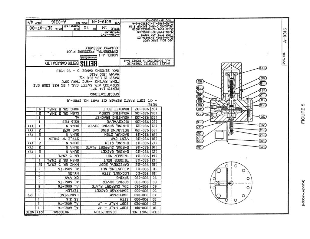
1 Bettis Canada Ltd A Street Edmonton, Alberta, Canada T6E 5V2 Tel: (780) EDMONTON Fax: (780) Service Manual BETTIS J1-RT2 RATE OF DROP LINEBREAK DETECTION SYSTEM CUSTOMER: P.O.#: W.O.#: TYPE: DATE: FACTORY SET: psi/min psi P/L SECTION PAGE I GENERAL DESCRIPTION & INFORMATION... 2 II INSTALLATION AND START-UP III CALIBRATION AND TESTING... 6 IV FUNCTION CHECK V TROUBLE-SHOOTING VI MAINTENANCE PROCEDURES VII DRAWINGS - Outline Drawing... FIG 3 - Schematic... FIG 4 - J-1 Pilot Assembly... FIG 5 - Manifold Assembly... FIG 6 - Rate of Drop vs P Calibration Charts... FIG 7 APPENDIX A: ALTERNATE PROCEDURES FOR SECTION III CALIBRATION AND TESTING AND SECTION IV FUNCTION CHECK I WPD/1 REV
2 SECTION I GENERAL DESCRIPTION & INFORMATION The Bettis J1-RT2 system is designed to automatically monitor a gas pipeline, and deliver a pneumatic signal if a pre-determined rate of pressure drop is exceeded. The unit is typically used to detect a pipeline break situation and signal a valve operator. The system consists of a rate tank, J-1 differential pressure pilot, restrictor, check valve, manifold assembly and associated tube, fittings, gauges and filters. The system works as follows: when pipeline pressure is rising, gas flows through the check valve and restrictor, into the rate tank. When pipeline pressure is falling, gas flows out of the rate tank, back to the pipeline through the restrictor only. The restrictor resists the flow creating a pressure drop which is sensed by the J-1 as differential pressure. The J-1 will send a pneumatic signal if the differential pressure exceeds its calibrated setting. The greater the rate of drop in the pipeline pressure, the greater the differential pressure across the J-1. The following abbreviations will be used: pipeline pressure rate of drop differential pressure P/L RoD P Normally, the pipeline will be operating at a steady or slowly changing pressure. When a pipeline break occurs, the RoD at the J1-RT2 sensing point will depend on the distance to the break. Greater distance to the break will decrease RoD at the sensing point. A compromise must be made in adjusting the RoD setpoint. It must be as low as possible to detect remote breaks, but not so low that normal pipeline pressure fluctuations will cause a false alarm. As indicated earlier, the J-1 differential pressure pilot does not respond directly to RoD but to P. The P depends on RoD, but also on: 1. P/L: The RoD required to generate a given P increases with higher P/L. 2. Time: After the initiation of a RoD due to a pipeline break the P takes time to reach its maximum value. These dependencies are inherent in this type of system. The time delay in reaching the maximum P necessitates the following clarification: P/L is the pipeline pressure occurring at the time that the maximum P is developed, not the pipeline pressure at the initiation of the RoD (refer to FIG 1). This time delay is apparent and accounted for in the FUNCTION CHECK procedure (SECTION IV). (i wpd/2)
3
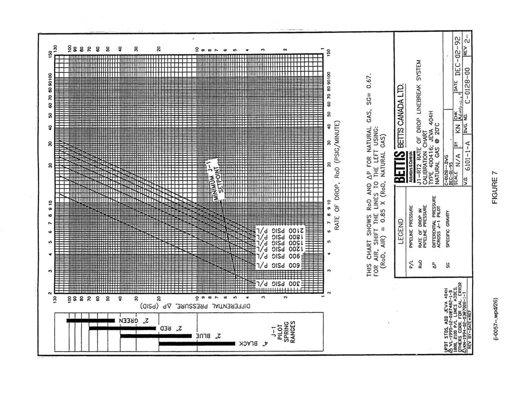
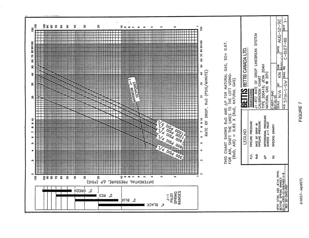
4 SECTION I GENERAL DESCRIPTION & INFORMATION - continued Each combination of restrictor and rate tank size has a specific CALIBRATION CHART (Refer to FIG 6), identified by a TYPE number which corresponds to the TYPE number stamped on the unit name plate. The CALIBRATION CHART maps the relationship between P, RoD and P/L. The J-1 pilot is calibrated to trip at a particular P by adjusting the spring preload or changing springs. The CALIBRATION CHART also indicates the P ranges of the four J-1 springs which may be used (stocked at the factory). The selection of restrictor is done at the factory based on the specified RoD range and P/L operating range. Specific instructions for reading the required P from the CALIBRATION CHART are given in Section III (4. J-1 P CALIBRATION). The CALIBRATION CHARTS are for natural gas with a specific gravity (SG) of.67 and temperature of 20bC. After correcting for SG and temperature, they will normally agree with field data within ±20% (on RoD). The inaccuracy is due to manufacturing tolerances and the fact that the chart P/L lines are adjusted from original data using air. Considering the above, the recommended uses of the CALIBRATION CHARTS are limited to the following: - Selection of the correct restrictor for an application (normally done at the factory). - Initial J-1 pilot calibration (normally done at the factory), to be verified at final installation using the FUNCTION CHECK procedure (Section IV). - Illustration of performance characteristics for training, calibration or troubleshooting purposes. Use of the CALIBRATION CHARTS to verify FUNCTION CHECK data is not recommended as it is complicated, (Corrections would generally have to be made for SG and temperature) and unnecessary, (the data from the FUNCTION CHECK procedure, stands by itself as proof that the system is operating to specification, provided the unit has been calibrated and tested per Section III). It is recommended that users establish their own baseline calibration records using the procedures in Section III and IV and keep calibration records. (i wpd/4)
5 SECTION II INSTALLATION AND START-UP GENERAL INFORMATION The unit can be installed remote from or on the valve operator. The following preparations are required: 1. Ensure the isolation valve on the pipeline is installed with take-off to top of pipeline to allow liquids to drain back into the line. 2. Ensure that pipe and tube to be used is free of chips and debris. 3. Use minimum 1/4 NPT or 3/8 tube, with support adequate to prevent vibration and strain on connections. An additional pre-filter is recommended (Refer to Section VI, item 4). It should be installed between the PIPELINE ISOLATION VALVE (FIG 4, item 101), and the customer supplied isolation valve at the pipeline take-off. CONNECTIONS (Refer to FIG 3) When the J1-RT2 System is shipped pre-installed on the valve operator, customer connections consist of: - High pressure pipeline gas connection to PIPELINE ISOLATION VALVE (pipeline connection "A", ¼ NPT female). When the J1-RT2 System is shipped separately, customer connections, in addition to above, include: - Low pressure supply connection to J-1 pilot valve (supply connection "C", ¼ NPT female, 150 psig max). - Low pressure signal connection to J-1 pilot valve (signal connection "B", ¼ NPT female). (i wpd/5)
6 SECTION II INSTALLATION AND START-UP - continued START UP (Refer to FIG 4) 1. OPERATION AND FUNCTION OF MANUAL VALVES a. PIPELINE ISOLATION VALVE (item 101): This valve is normally open. Closing this valve isolates the system from the pipeline. b. RATE TANK DRAIN VALVE (item 107): This valve is normally closed and plugged. Unplug and open to depressurize the J1-RT2 system or drain condensate. 2. START-UP a. Check and close all manual control valves. b. Open the main isolation valve on the pipeline (customer supplied). c. SLOWLY open PIPELINE ISOLATION VALVE (item 101) to pressurize system. d. When flow into the RATE TANK has stopped, the signal pressure gauge should indicate if a signal is being applied to (or removed from) the valve operator control package. e. The Line Valve (item 2) should be able to be opened and it should remain open. LEAK TEST ALL FITTINGS AND CONNECTIONS WITH SOAPY WATER. (i wpd/6)
7 SECTION III CALIBRATION AND TESTING THREE REQUIREMENTS FOR CORRECT J1-RT2 OPERATION: CORRECT J-1 PILOT CALIBRATION: Verify using the J-1 P CALIBRATION procedure in this section. LEAK-TIGHT HIGH PRESSURE SIDE: Verify using the PRESSURE HOLD TEST procedure in this section. UNOBSTRUCTED RESTRICTOR AND FILTERS: Verify using the PLUGGING TEST procedure in this section. CALIBRATION AND TESTING PROCEDURES: For routine calibration and testing, the following steps (1 to 7) are to be executed in sequence. NOTE: THESE PROCEDURES REQUIRE BETTIS CALIBRATION KIT, PART NO REFER TO APPENDIX A FOR AN ALTERNATE PROCEDURE BASED ON SIMPLIFIED EQUIPMENT. THIS SIMPLIFIED EQUIPMENT IS SPECIFIED IN THE PROCEDURE AND MAY BE SUPPLIED BY THE USER. 1. DISARM SYSTEM Isolate or disarm controls and equipment downstream of the J1-RT2 output signal to prevent inadvertent operation or alarms (Follow applicable procedures and operating instructions). Depending on where and how this is done, selected downstream controls can be left active. The function of these controls can then be verified when J1-RT2 output signals are generated during the following procedures. 2. CHECK FOR EXTERNAL LEAKS: While the J1-RT2 system is still pressurized, check for external leaks at all connections using soapy water. Fix any leaks before proceeding. (i wpd/7)
8 SECTION III CALIBRATION AND TESTING - continued 3. SETUP TEST EQUIPMENT SEE FIG 2, "SETUP FOR J1-RT2 CALIBRATION AND TESTING WITH CALIBRATION KIT" CAUTION: CAUTION: DISARM AND DEPRESSURIZE BEFORE ATTEMPTING SERVICE; Close the PIPELINE TAKE-OFF VALVE and de-pressurize the system by opening the RATE TANK DRAIN VALVE. Ensure that contaminants (eg. dust, soapy water, etc.) do not enter at the HIGH or LOW PRESSURE TEST CONNECTIONS. a. Connect HIGH PRESSURE CONNECTION on CALIBRATION KIT PANEL to HIGH PRESSURE TEST CONNECTION on the J1-RT2 MANIFOLD (3/8 tube fitting). b. Connect LOW PRESSURE CONNECTION on CALIBRATION KIT PANEL to LOW PRESSURE TEST CONNECTION on the J1-RT2 MANIFOLD (1/4 tube fitting). c. Connect PIPELINE CONNECTION on CALIBRATION KIT PANEL to a PIPELINE PRESSURE TAP (or between the PIPELINE TAKE-OFF VALVE and the PIPELINE ISOLATION VALVE). Ensure: 1. All CALIBRATION KIT PANEL valves are closed except the METERING VALVE which should be near fully open. 2. GAUGE SELECTOR VALVE is set to FUNCTION CHECK. 3. All connections are made leak tight. To pressurize system for leak checking connections: - Open PIPELINE TAKE OFF VALVE and PIPELINE ISOLATION VALVE - Open HIGH PRESSURE BLOCK VALVE - Slowly open CALIBRATION PANEL NEEDLE VALVE allowing system to fill and stabilize To vent off: - Close PIPELINE TAKE OFF VALVE - Open RATE TANK DRAIN VALVE - Open LOW PRESSURE BLOCK VALVE (i wpd/8)
9
10 SECTION III CALIBRATION AND TESTING - continued 4. J-1 P CALIBRATION a. Remove U-TUBE and install caps on fittings. b. Open the LOW PRESSURE SIDE to atmosphere by fully opening the METERING VALVE and the LOW PRESSURE BLOCK VALVE. Close the RATE TANK DRAIN VALVE and PANEL NEEDLE VALVE. Set the GAUGE SELECTOR VALVE to the SETPOINT CHECK GAUGE. c. Open the HIGH PRESSURE BLOCK VALVE and slowly increase pressure on the HIGH PRESSURE SIDE using the NEEDLE VALVE. Note the reading on the SETPOINT CHECK GAUGE when the J-1 switches (ie. MICROVALVE toggles). Close NEEDLE VALVE after J-1 switches. d. Repeat test, vent the HIGH PRESSURE SIDE by closing the NEEDLE VALVE and opening the RATE TANK DRAIN VALVE, and repeat procedure b and c above. e. Compare the J-1 switch pressure to the required P*. f. Adjust the J-1 spring load if required (turn adjusting nut FIG 4, item 111) and repeat steps b, c and d until switching occurs at the required P. If the required P is outside the range of the J-1 spring, contact the factory for an alternate. * If the required P is unknown or not yet established, use the CALIBRATION CHART to find the P corresponding to the specified/desired rate-of-drop (RoD) and pipeline pressure (P/L). (If the pipeline operates over a wide pressure range, a typical pressure must be selected). Use of CALIBRATION CHART to find P: Find the specified/desired RoD along the horizontal axis and trace a line upward to where it intersects the specified/desired P/L line (interpolation between P/L lines may be required). From this intersection trace a horizontal line to the vertical axis and read the P value. Refer to comments on the CALIBRATION CHART in Section I. (i wpd/10)
11 SECTION III CALIBRATION AND TESTING - continued 5. PRESSURE HOLD TEST a. Ensure the PIPELINE ISOLATION VALVE is closed. Depressurize the system by venting the RATE TANK (open the RATE TANK DRAIN VALVE). Disconnect the hose from the PIPELINE PRESSURE TAP and PANEL PIPELINE CONNECTION. Re-install plugs at both fittings. b. If not done in step 4a then, remove the U-TUBE and install tubing caps on the fittings. CAUTION: Ensure that contaminants (eg. dust, soapy water etc.) do not enter at these fittings. Close the RATE TANK DRAIN VALVE and HIGH PRESSURE BLOCK VALVE. CAUTION: Ensure that plugs have been installed leak tight. Check with soapy water when the system is pressurized in step c. Set the GAUGE SELECTOR VALVE to the SETPOINT CHECK GAUGE. c. LOW PRESSURE HOLD TEST: Close the LOW PRESSURE BLOCK VALVE. Pressurize the HIGH PRESSURE SIDE to 20 psi by opening the PIPELINE ISOLATION VALVE (the flow through the check valve will require it to open and reseat at low pressure resulting in a worst case test). Stabilize the pressure reading for one minute then vent the LOW PRESSURE SIDE by opening the LOW PRESSURE BLOCK VALVE (METERING VALVE near fully open). Monitor the SETPOINT CHECK GAUGE for 3 minutes. The maximum allowable pressure loss is 10% of RoD over 3 minutes (eg. if RoD = 20 psi/min then allowable pressure loss over 3 minutes is 2 psi or less). d. HIGH PRESSURE HOLD TEST: Close the LOW PRESSURE BLOCK VALVE. Pressurize the HIGH PRESSURE SIDE to 500 psi (or to available P/L if less) by opening the PIPELINE ISOLATION VALVE. Stabilize the pressure reading for one minute then vent the LOW PRESSURE SIDE by opening the LOW PRESSURE BLOCK VALVE and metering valve is nearly full open. Monitor the SETPOINT CHECK GAUGE for 3 minutes. The maximum allowable pressure loss is 10% of RoD over 3 minutes (see example in step c above). (i wpd/11)
12 SECTION III CALIBRATION AND TESTING - continued e. If the maximum allowable pressure loss rates are exceeded, there is a leak in the HIGH PRESSURE SIDE which must be traced and fixed. A failure of the LOW PRESSURE HOLD TEST is likely due to a faulty check valve. A failure of the HIGH PRESSURE HOLD TEST is likely due to leaking tube fittings, valves or internal leakage through the J-1 diaphragm or the check valve (refer to Section VI, MAINTENANCE PROCEDURES). Depressurize the system by venting the RATE TANK (open the RATE TANK DRAIN VALVE). 6. PLUGGING TEST a. Ensure the PIPELINE ISOLATION VALVE is closed and the system is depressurized (ie. the RATE TANK DRAIN VALVE is open). b. Re-install the U-TUBE. Ensure that these tube connections are leak tight as they are on the HIGH PRESSURE SIDE. Check with soapy water after the system is pressurized. CAUTION: Use minimal torque when remaking U-TUBE connections to extend tube life. c. Close the RATE TANK DRAIN VALVE and LOW PRESSURE BLOCK VALVE. Ensure the METERING VALVE is near fully open, the HIGH PRESSURE BLOCK VALVE is closed and the GAUGE SELECTOR VALVE is on SETPOINT CHECK GAUGE. d. Pressurize the system to 300 psi by opening the PIPELINE ISOLATION VALVE. Stabilize the pressure for one minute (If pressure will not stabilize, there is a leak in the system which must be fixed before running the test. See item 5, PRESSURE HOLD TEST). e. Open the LOW PRESSURE BLOCK VALVE and simultaneously start TIMER. f. Record pressure reading at 90 seconds and close the LOW PRESSURE BLOCK VALVE. g. Compare this to the appropriate MAXIMUM END PRESSURE value in the table below. If the end pressure is above the maximum, there is plugging or obstruction of the restrictor or filters (refer to Section VI, MAINTENANCE PROCEDURES). (i wpd/12)
13 SECTION III CALIBRATION AND TESTING - continued J1-RT2 TYPE NO. MAXIMUM END PRESSURE (psig) NATURAL GAS AIR, NITROGEN RESTORE THE UNIT TO OPERATING CONDITION (or proceed to the FUNCTION CHECK procedure, Section IV.) CAUTION: Ensure that all connections are leak tight, especially on the HIGH PRESSURE SIDE (ie. HIGH PRESSURE TEST CONNECTION plug, U-TUBE and RATE TANK DRAIN VALVE plug. Check with soapy water when the system is repressurized). (i wpd/13)
14 SECTION IV FUNCTION CHECK The J1-RT2 function and calibration can be checked in the field by doing RoD SIMULATION RUNS. Using PIPELINE PRESSURE repeat runs at different RoDs to approximate the "SETPOINT RoD" (ie. the RoD which generates just enough P to activate the J-1 pilot at a particular P/L). This process will give two RoD values: - The upper value: the lowest RoD at which the J-1 switched. - The lower value: the highest RoD at which the J-1 did not switch. The closer the two values are the more accurately the SETPOINT RoD is determined. Each value of RoD will have a corresponding value of P/L which is also recorded. NOTE: The THREE REQUIREMENTS FOR CORRECT J1-RT2 OPERATION (see Section III) are the first priority and must be met for this function check to be valid. PROCEDURE: 1. DISARM SYSTEM (See Section III, step 1) 2. SETUP TEST EQUIPMENT This is the same as Section III, step 3, except the hose connecting the PIPELINE PRESSURE TAP to the CALIBRATION KIT PANEL PIPELINE CONNECTION is not required, and the RATE TANK DRAIN VALVE is closed and plugged. Set the GAUGE SELECTOR VALVE to FUNCTION CHECK GAUGE. 3. RoD SIMULATION RUNS Each run must have the same starting pressure (ie. P@T = 0:00). Use a starting pressure which is equal to or slightly less than typical pipeline operating pressure (Using the same starting pressure for future function checks will allow direct comparison of data). Use the table below to find the appropriate value for T1 and T2. (i wpd/14)
15 SECTION IV FUNCTION CHECK - continued Each RoD SIMULATION RUN consists of the following: a. Using available PIPELINE PRESSURE charge the system to the starting pressure by opening the PIPELINE ISOLATION VALVE (Ensure the LOW PRESSURE BLOCK VALVE is closed). b. Close the PIPELINE ISOLATION VALVE and set the METERING VALVE. (The METERING VALVE setting controls RoD and must be determined by trial and error). c. Stabilize at the starting pressure for at least one minute. d. Open the LOW PRESSURE BLOCK VALVE and start the TIMER (T=0:00) simultaneously. e. Record P@T=T1 and T2. Note whether and when the J-1 switches. f. After T=T2, close the LOW PRESSURE BLOCK VALVE to end the run. g. To calculate the RoD for the run use: RoD=[(P@T=T1)-(P@T=T2)]/2. To calculate the approximate P/L for the run use: P/L=(P@T=T1)-(J-1 P setting). h. If the J-1 switched, reduce RoD (ie. close down metering valve slightly) for the next run. If the J-1 did not switch, increase RoD for the next run. J1-RT2 TYPE NO T1 0:30 1:00 2:00 3:00 T2 2:30 3:00 4:00 5:00 (i wpd/15)
16 SECTION IV FUNCTION CHECK - continued This procedure can be used even if the available PIPELINE PRESSURE (ie. starting pressure for each run) is below normal. However, since all the variables are interdependent, the setpoint RoD and P/L values will be correspondingly reduced so they cannot be directly compared to "spec", or previously established baseline values. The METERING VALVE used in the FUNCTION CHECK procedure has a very small annular gap between the orifice and the needle. Due to the this and the large pressure drop across it, freeze-off may occur when the ambient temperature is low or when the pipeline gas dew point is high. This will cause difficulty in adjusting and achieving a continuous RoD in the RoD SIMULATION RUNS. The remedy is to apply heat to the body of the METERING VALVE, either by hand contact, or a chemical or electric heating pad or similar device, at 80bC ± 20bC. 4. RESTORE THE UNIT TO OPERATING CONDITION Depressurize and disconnect test equipment. Install caps on HIGH PRESSURE and LOW PRESSURE TEST CONNECTIONS. CAUTION: Ensure that all connections are leak tight, especially on the HIGH PRESSURE SIDE (ie. HIGH PRESSURE TEST CONNECTION plug, U-TUBE and RATE TANK DRAIN VALVE plug). Check with soapy water when system is re-pressurized. (i wpd/16)
17 SECTION V TROUBLE-SHOOTING In general, the J1-RT2 system will be trouble free as long as the "THREE REQUIREMENTS FOR CORRECT OPERATION" are met (refer to Section III). In case of trouble the procedures below should help to isolate the problem. See also the remainder of this manual for correct operating procedures and detailed description of components. Re-check assembly and operating procedures if problems arise immediately after shutdown for maintenance or calibration. CAUTION: Before doing any work on the system, refer to SECTION VI, MAINTENANCE PROCEDURES, item 1 "DISARM AND DEPRESSURIZE BEFORE REMOVAL/DISASSEMBLY" PROBLEM CAUSE REMEDY A) J1-RT2 FAILS TO ACTIVATE on ESD condition (high RoD) 1. J-1 diaphragm cracked or leaking 2. External leakage (Confirm by doing PRESSURE HOLD TEST) 3. By-pass check valve inside MANIFOLD is leaking (confirm by doing PRESSURE HOLD TEST) 1. Replace diaphragm; refer to Section VI, item 8 2. Check and correct 3. Check if there is any foreign material at the poppet of the check valve; refer to Section VI, item 5 4. Dirty filters 4. Clean or replace filters; refer to Section VI, item 3 and 4 B) J1 PILOT FAILS TO ACTIVATE on ESD condition (high RoD, high P) 1. J-1 setpoint too high 1. Refer to Section III, item 4 2. J-1 diaphragm stiff or shaft jammed (confirm by removing spring and checking for ¼" free travel) 2. Clean and lubricate parts, replace diaphragm, refer to Section VI, item 8 (i wpd/17)
18 SECTION V TROUBLESHOOTING - continued PROBLEM CAUSE REMEDY C) NO SIGNAL OUTPUT FROM J-1 MICROVALVE on ESD condition. 1. Insufficient lift on valve (travel of microvalve) 2. Microvalve is clogged by foreign material 3. Supply filters are dirty, flow rate is then restricted 4. Regulator setting is incorrect (low pressure output only) 1. See J-1 pilot drawing; check the bracket bolt tightness and trigger bolt adjustment; refer to Section VI, item 7 2. Clean valve passages 3. Clean filter elements 4. Check regulator setpoint, adjust if necessary D) SYSTEM ACTIVATES in absence of ESD condition (false signal) 1. J-1 setpoint too low 1. Refer to Section III, item 4 2. P/L is less than RATE TANK PRESSURE while attempting to reset 3. Low RoD develops high P due to clogged restrictor 2. Allow to stabilize 3. Check and clean restrictor; refer to Section VI, item 6 (i wpd/18)
19 SECTION VI MAINTENANCE PROCEDURES 1. DISARM AND DEPRESSURIZE BEFORE REMOVAL/DISASSEMBLY. The following steps are to be carried out when removing/disassembling any part of the linebreak system, for reasons of safety. a. Isolate or disarm downstream controls and equipment to prevent inadvertent operation or alarms. b. Close isolation valve at the pipeline (ie. upstream of all linebreak system components). c. Depressurize the system by opening the RATE TANK DRAIN VALVE. 2. STANDARD PRACTICES FOR MAINTENANCE a. Clean around any parts to be removed before removal. b. Note or mark piping or parts orientation before removal to facilitate re-assembly. c. Clean all parts before assembly, particularly sealing surfaces. d. Lubricate all o-rings and sliding surfaces. e. Lubricate all threads to prevent galling. 3. MAINTENANCE OF MANIFOLD FILTER ELEMENTS (Refer to FIG 6) To maintain free flow and prevent false shutdowns, the two filter elements in the MANIFOLD should be cleaned, or replaced, at least every six months until service experience indicates a more suitable interval. To do this: a. Remove one of the FILTER END PLUGS (on left side of MANIFOLD). b. Remove the spring. c. Tap or pry filter element lightly on side to break loose from the tapered sealing bore. d. Clean the filter element. e. Insert the clean filter element into the bore. Tap lightly with smooth faced tool to re-seat the element in tapered bore. f. Replace spring and END PLUG. Tighten END PLUG securely. g. Repeat 3 through 8 for second filter. (i wpd/19)
20 SECTION VI MAINTENANCE PROCEDURES - continued 4. MAINTENANCE OF OPTIONAL PREFILTER (Refer to FIG 3) An optional prefilter (item 170) upstream of MANIFOLD connection (Port "A") is highly recommended in wet or dirty service to entrap foreign particles and moisture which could cause rapid plugging of the manifold filter elements. Inspect and/or replace the filter cartridge on the same schedule as the manifold filter elements (refer to item 3). Ensure that the filter body is depressurized before opening. 5. CHECK VALVE REMOVAL/INSPECTION (Refer to FIG 6) Remove CHECK VALVE RETAINER PLUG and NPT pipe plug at opposite side of MANIFOLD. Push the check valve out using a suitable, non metal tool (to avoid damage or scratches). Check for moisture or debris inside check valve body or between o-ring and poppet. If present, hold the poppet off the seat and clear with compressed air. Check for free movement of the poppet. Inspect the sealing surface in the manifold bore and condition of the external o-ring on the check valve body. If the valve still leaks, the internal o-ring is probably damaged and the valve requires replacement. 6. RESTRICTOR MAINTENANCE (Refer to FIG 6) To ensure correct operation the RESTRICTOR must be free of obstruction. The manifold filters and recommended prefilter are meant to keep the restrictor clean and dry. However, if plugging is suspected, follow the procedure below: a. Remove RESTRICTOR HOUSING from MANIFOLD. (The restrictor cannot be removed from the housing without special tools.) b. Soak in solvent for a 24 hour period. c. To remove solvent, and provide proper filtering, attach the RESTRICTOR HOUSING to the manifold via the U-TUBE only (ie. do not screw housing into manifold), then blow air through the RESTRICTOR by pressurizing the RATE TANK side of the system. (i wpd/20)
21 SECTION VI MAINTENANCE PROCEDURES - continued d. Reinstall RESTRICTOR HOUSING and U-TUBE on the MANIFOLD. e. Verify correct installation of the manifold filters (refer to item c in this section). 7. J-1 MICROVALVE ALIGNMENT (Refer to FIG 5) a. Remove the spring (item 90) b. Pressurize the HIGH PRESSURE SIDE to 120 psi. Adjust the trigger bolt outwards until the microvalve (item 130) is triggered. Lock in place with locknut. c. The microvalve lever should have approximately to inches additional over travel. Do not use excessive force on the lever. d. Vent the HIGH PRESSURE SIDE and re-install the spring. 8. J-1 PILOT INSPECTION/MAINTENANCE (Refer to FIG 5) a. Disconnect the tubes at the HIGH PRESSURE and LOW PRESSURE fittings, remove the J-1 spring and check that the diaphragm mechanism travels from stop to stop (about ¼" total travel) without binding or catching. b. Apply about 100 psi at the HIGH PRESSURE fitting and check for leakage at the LOW PRESSURE fitting. This can be done by installing a tube cap loosely and checking for bubbles with soapy water. Alternatively, a ¼" plastic tube can be connected to the LOW PRESSURE fitting with the free end submerged in c" in water. In either case, there should be no sustained bubbling. c. If any problems are detected, obtain a spare parts kit and rebuild. (i wpd/21)
22
23
24
25
26
27

28
29 APPENDIX A ALTERNATE PROCEDURES FOR SECTION III CALIBRATION AND TESTING AND SECTION IV FUNCTION CHECK THESE ALTERNATE PROCEDURES ARE BASED ON SIMPLIFIED TEST EQUIPMENT, SPECIFIED IN THE PROCEDURE, WHICH MAY BE SUPPLIED BY THE USER. (i wpd/30)
30 APPENDIX A SECTION III CALIBRATION AND TESTING THREE REQUIREMENTS FOR CORRECT J1-RT2 OPERATION: CORRECT J-1 PILOT CALIBRATION: Verify using the J-1 P CALIBRATION procedure in this section. LEAK-TIGHT HIGH PRESSURE SIDE: Verify using the PRESSURE HOLD TEST procedure in this section. UNOBSTRUCTED RESTRICTOR AND FILTERS: Verify using the PLUGGING TEST procedure in this section. CALIBRATION AND TESTING PROCEDURES: For routine calibration and testing, the following steps (1 to 7) are to be executed in sequence. 1. DISARM SYSTEM Isolate or disarm controls and equipment downstream of the J1-RT2 output signal to prevent inadvertent operation or alarms (Follow applicable procedures and operating instructions). Depending on where and how this is done, selected downstream controls can be left active. The function of these controls can then be verified when J1-RT2 output signals are generated during the following procedures. 2. CHECK FOR EXTERNAL LEAKS While the J1-RT2 system is still pressurized, check for external leaks at all connections using soapy water. Fix any leaks before proceeding. (i wpd/31)
31
32 APPENDIX A SECTION III CALIBRATION AND TESTING - continued 4. J-1 P CALIBRATION a. Open the LOW PRESSURE SIDE to atmosphere by fully opening the METERING VALVE and the LOW PRESSURE BLOCK VALVE. b. Slowly increase pressure on the HIGH PRESSURE SIDE using the NEEDLE VALVE, and note the reading on the PRESSURE GAUGE when the J-1 switches (ie. MICROVALVE toggles). (When the HIGH PRESSURE SIDE is pressurized there will be a small flow through the restrictor). c. After the J-1 switches, shut the NEEDLE VALVE and vent the HIGH PRESSURE SIDE by opening the HIGH PRESSURE BLOCK VALVE. d. Compare the J-1 switch pressure to the required P*. e. Adjust the J-1 spring load if required (turn adjusting nut FIG 4, item 111) and repeat steps b, c and d until switching occurs at the required P. If the required P is outside the range of the J-1 spring, contact the factory for an alternate. * If the required P is unknown or not yet established, use the CALIBRATION CHART to find the P corresponding to the specified/desired RoD and P/L. (If the pipeline operates over a wide pressure range, a typical pressure must be selected). Use of CALIBRATION CHART to find P: Find the specified/desired RoD along the horizontal axis and trace a line upward to where it intersects the specified/desired P/L line (interpolation between P/L lines may be required). From this intersection trace a horizontal line to the vertical axis and read the P value. Refer to comments on the CALIBRATION CHART in Section I. 5. PRESSURE HOLD TEST a. Ensure the PIPELINE ISOLATION VALVE is closed. Depressurize the system by venting the RATE TANK (open the DRAIN VALVE and HIGH PRESSURE BLOCK VALVE). (i wpd/33)
33 APPENDIX A SECTION III CALIBRATION AND TESTING - continued b. Remove the U-TUBE and install tubing caps on the fittings (the cap on the HIGH PRESSURE SIDE must be installed leak tight to pass the pressure hold tests). CAUTION: Ensure that contaminants (eg. dust, soapy water etc.) do not enter at these fittings as they are internal to the manifold filters. Close the RATE TANK DRAIN VALVE, leaving the HIGH PRESSURE BLOCK VALVE open. c. LOW PRESSURE HOLD TEST: Close the LOW PRESSURE BLOCK VALVE. Pressurize the HIGH PRESSURE SIDE TO 20 psi by opening the PIPELINE ISOLATION VALVE (the flow through the check valve will require it to open and reseat at low pressure resulting in a worst case test). Stabilize the pressure reading for one minute then vent the LOW PRESSURE SIDE by opening the LOW PRESSURE BLOCK VALVE. Monitor the PRESSURE GAUGE for 3 minutes. The maximum allowable pressure loss is 10% of RoD over 3 minutes (eg. if RoD = 20 psi/min then allowable pressure loss over 3 minutes is 2 psi or less). d. HIGH PRESSURE HOLD TEST: Close the LOW PRESSURE BLOCK VALVE. Pressurize the HIGH PRESSURE SIDE to 500 psi (or to available P/L if less) by opening the PIPELINE ISOLATION VALVE. Stabilize the pressure reading for one minute then vent the LOW PRESSURE SIDE by opening the LOW PRESSURE BLOCK VALVE. Monitor the pressure gauge for 3 minutes. The maximum allowable pressure loss is 10% of RoD over 3 minutes (see example in step c above). e. If the maximum allowable pressure loss rates are exceeded, there is a leak in the HIGH PRESSURE SIDE which must be traced and fixed. A failure of the LOW PRESSURE HOLD TEST is likely due to a faulty check valve. A failure of the HIGH PRESSURE HOLD TEST is likely due to leaking tube fittings, valves or internal leakage through the J-1 diaphragm or the check valve (refer to Section VI, MAINTENANCE PROCEDURES). Depressurize the system by venting the RATE TANK and re-install the U-TUBE. f. Ensure that these tube connections are leak tight as they are on the HIGH PRESSURE SIDE. Check with soapy water after the system is pressurized. (i wpd/34)
34 APPENDIX A SECTION III CALIBRATION AND TESTING - continued 6. PLUGGING TEST a. Ensure the PIPELINE ISOLATION VALVE is closed and the system is depressurized (ie. the RATE TANK DRAIN VALVE and HIGH PRESSURE BLOCK VALVE are open). b. Close the RATE TANK DRAIN VALVE and LOW PRESSURE BLOCK VALVE, and fully open the METERING VALVE (leave the HIGH PRESSURE BLOCK VALVE open). c. Pressurize the system to 300 psi by opening the PIPELINE ISOLATION VALVE. Stabilize the pressure for one minute (If pressure will not stabilize, there is a leak in the system which must be fixed before running the test. See item 5, PRESSURE HOLD TEST). d. Open the LOW PRESSURE BLOCK VALVE and simultaneously start TIMER. e. Record pressure reading at 90 seconds and close the LOW PRESSURE BLOCK VALVE. f. Compare this to the appropriate MAXIMUM END PRESSURE value in the table below. If the end pressure is above the maximum, there is plugging or obstruction of the restrictor or filters (refer to Section VI, MAINTENANCE PROCEDURES). J1-RT2 TYPE NO. MAXIMUM END PRESSURE (psig) NATURAL GAS AIR, NITROGEN Restore the unit to operating condition or proceed to the FUNCTION CHECK procedure, Section IV. Ensure that all remade connections are leak tight, especially on the HIGH PRESSURE SIDE (ie. cap for HIGH PRESSURE TEST CONNECTION and plug at the RATE TANK DRAIN VALVE. Check with soapy water). (i wpd/35)
35 APPENDIX A SECTION IV FUNCTION CHECK The J1-RT2 function and calibration can be checked in the field by doing RoD SIMULATION RUNS. Using P/L repeat runs at different RoDs to approximate the "SETPOINT RoD" (ie. the RoD which generates just enough P to activate the J-1 pilot at a particular P/L). This process will give two RoD values: - The upper value: the lowest RoD at which the J-1 switched. - The lower value: the highest RoD at which the J-1 did not switch. The closer the two values are the more accurately the SETPOINT RoD is determined. Each value of RoD will have a corresponding value of P/L which is also recorded. NOTE: The THREE REQUIREMENTS FOR CORRECT J1-RT2 OPERATION (see Section III) are the first priority and must be met for this function check to be valid. PROCEDURE: 1. DISARM SYSTEM (See Section III, item 1) 2. SETUP TEST EQUIPMENT This is the same as Section III, item 3 except the HIGH PRESSURE BLOCK VALVE, NEEDLE VALVE and HOSE are removed, and the RATE TANK DRAIN VALVE is closed and plugged. If the normal PIPELINE PRESSURE range exceeds the range of the gauge used in Section III (ie psi) then install a gauge of suitable range with resolution of no greater than 10 psi/div. 3. RoD SIMULATION RUNS Each run must have the same starting pressure (ie. P@T = 0:00). Use a starting pressure which is equal to or slightly less than typical pipeline operating pressure (Using the same starting pressure for future function checks will allow direct comparison of data). Use the table below to find the appropriate value for T1 and T2. (i wpd/36)
36 APPENDIX A SECTION IV FUNCTION CHECK - continued Each RoD SIMULATION RUN consists of the following: a. Using available PIPELINE PRESSURE, charge the system to the starting pressure by opening the PIPELINE ISOLATION VALVE (Ensure the LOW PRESSURE BLOCK VALVE is closed). b. Close the PIPELINE ISOLATION VALVE and set the METERING VALVE. (The METERING VALVE setting controls RoD and must be determined by trial and error). c. Stabilize at the starting pressure for at least one minute. d. Open the LOW PRESSURE BLOCK VALVE and start the TIMER (T=0:00) simultaneously. e. Record P@T=T1 and T2. Note whether and when the J-1 switches. f. After T=T2, close the LOW PRESSURE BLOCK VALVE to end the run. g. To calculate the RoD for the run use: RoD=[(P@T=T1)-(P@T=T2)]/2. To calculate the approximate P/L for the run use: P/L=(P@T=T1)-(J-1 P setting). h. If the J-1 switched, reduce RoD (ie. close down metering valve slightly) for the next run. If the J-1 did not switch, increase RoD for the next run. J1-RT2 TYPE NO T1 0:30 1:00 2:00 3:00 T2 2:30 3:00 4:00 5:00 (i wpd/37)
37 APPENDIX A SECTION IV FUNCTION CHECK - continued This procedure can be used even if the available PIPELINE PRESSURE (ie. starting pressure for each run) is below normal. However, since all the variables are interdependent, the setpoint RoD and P/L values will be correspondingly reduced so they cannot be directly compared to "spec", or previously established baseline values. 4. RESTORE THE UNIT TO OPERATING CONDITION Depressurize system and disconnect test equipment. Install caps on HIGH PRESSURE and LOW PRESSURE TEST CONNECTIONS. CAUTION: Ensure that all connections are leak tight especially on the HIGH PRESSURE SIDE (ie. HIGH PRESSURE TEST CONNECTION plug, U-TUBE and RATE TANK DRAIN VALVE plug). Check with soapy water when system is re-pressurized. (i wpd/38 orig:ag/tl-1992 rev6:ag/mc app dist:(ef)o);(sm)p)
SERVICE MANUAL No. I-0043
 Bettis Canada Ltd. 4112 91A Street Edmonton, Alberta, Canada T6E 5V2 Tel: (403) 450-3600 Fax: (403) 450-1400 SERVICE MANUAL No. I-0043 Edmonton GAS/HYDRAULIC ADDITIONAL COMPONENTS CUSTOMER: P.O.#: W.O.#:
INSTALLATION INSTRUCTIONS. CVS 67CFR Pressure Reducing Instrument Supply Regulator INTRODUCTION
 INSTALLATION INSTRUCTIONS CVS 67CFR Pressure Reducing Instrument Supply Regulator INTRODUCTION The CVS Controls 67CFR Filter regulator is a pressure reducing supply regulator typically used for pneumatic
Installation, Operation and Maintenance Manual for Back Pressure Regulator
 Installation, Operation and Maintenance Manual for Back Pressure Regulator Model 8860 2009 Groth Corporation IOM-8860 Rev. B 12541 Ref. ID: 95565 Page 2 of 13 Table of Contents I. INTRODUCTION 3 II. DESIGN
LRS(H)4 Pressure-Reducing Regulator User Manual
4 Pressure-Reducing Regulator User Manual") LRS(H)4 Pressure-Reducing Regulator User Manual Read the complete manual before installing and using the regulator. 2 Safe Product Selection When selecting a product, the total system design must be considered
LRS(H)4 Pressure-Reducing Regulator User Manual Read the complete manual before installing and using the regulator. 2 Safe Product Selection When selecting a product, the total system design must be considered
RD(H)20/25 Pressure-Reducing Regulator User Manual
20/25 Pressure-Reducing Regulator User Manual") RD(H)20/25 Pressure-Reducing Regulator User Manual Read the complete manual before installing and using the regulator. 2 Safe Product Selection When selecting a product, the total system design must be
RD(H)20/25 Pressure-Reducing Regulator User Manual Read the complete manual before installing and using the regulator. 2 Safe Product Selection When selecting a product, the total system design must be
Installation Operation Maintenance. Bermad Level Control Valve with Modulating Horizontal Float Pilot valve One Way Flow IOM.
 Bermad Level Control Valve with Modulating Horizontal Float Pilot valve One Way Flow Model: FP 450-80 Installation Operation Maintenance PAGE 1 OF 5 1. Safety First BERMAD believes that the safety of personnel
OPERATION MANUAL NTF-60 Plus
 OPERATION MANUAL NTF-60 Plus Nitrogen Tire Filling Valve Stem Caps (Qty=200) Order P/N 436075 RTI Technologies, Inc 10 Innovation Drive York, PA 17402 800-468-2321 www.rtitech.com 035-81264-00 (Rev A)
OPERATING AND MAINTENANCE MANUAL
 Series 4300 Engineered Performance TABLE OF CONTENTS 0 INTRODUCTION 1 1 Scope 1 2 Description 1 3 Specifications 1 0 INSTALLATION 1 1 Mounting 1 2 Piping 1 1 Connecting Process Pressure 2 2 Vent Connections
LRS(H)4 USER MANUAL. Read the complete manual before installing and using the regulator.
4 USER MANUAL. Read the complete manual before installing and using the regulator.") LRS(H)4 USER MANUAL Read the complete manual before installing and using the regulator. WARNING INCORRECT OR IMPROPER USE OF THIS PRODUCT CAN CAUSE SERIOUS PERSONAL INJURY AND PROPERTY DAMAGE. Due to the
LRS(H)4 USER MANUAL Read the complete manual before installing and using the regulator. WARNING INCORRECT OR IMPROPER USE OF THIS PRODUCT CAN CAUSE SERIOUS PERSONAL INJURY AND PROPERTY DAMAGE. Due to the
RS(H)10,15 USER MANUAL. Read the complete manual before installing and using the regulator.
10,15 USER MANUAL. Read the complete manual before installing and using the regulator.") RS(H)10,15 USER MANUAL Read the complete manual before installing and using the regulator. WARNING INCORRECT OR IMPROPER USE OF THIS PRODUCT CAN CAUSE SERIOUS PERSONAL INJURY AND PROPERTY DAMAGE. Due to
RS(H)10,15 USER MANUAL Read the complete manual before installing and using the regulator. WARNING INCORRECT OR IMPROPER USE OF THIS PRODUCT CAN CAUSE SERIOUS PERSONAL INJURY AND PROPERTY DAMAGE. Due to
OPERATION MANUAL NTF-15
 OPERATION MANUAL NTF-15 Nitrogen Tire Filling Valve Stem Caps (Qty=200) Order P/N 436075 RTI Technologies, Inc 10 Innovation Drive York, PA 17402 800-468-2321 www.rtitech.com 035-81235-00 (Rev B) TABLE
Oxygen Usage Best Practice Guide
 Oxygen Usage Best Practice Guide 1. Introduction Oxygen enriched systems possess a risk of fire and explosion since ignition and combustion hazards are present in all oxygen systems, and oxygen related
RHPS Series RD(H)F40 User Manual. Read the complete manual before installing and using the regulator.
F40 User Manual. Read the complete manual before installing and using the regulator.") RHPS Series RD(H)F40 User Manual Read the complete manual before installing and using the regulator. 2 WARNING Before removing a regulator from the system for service, you must depressurize system purge
RHPS Series RD(H)F40 User Manual Read the complete manual before installing and using the regulator. 2 WARNING Before removing a regulator from the system for service, you must depressurize system purge
Pressure Dump Valve Service Kit for Series 2300 Units
 Instruction Sheet Pressure Dump Valve Service Kit for Series 00 Units. Overview The Nordson pressure dump valve is used to relieve hydraulic pressure instantly in Series 00 applicator tanks when the unit
PRS(TC)4,8 USER MANUAL. Read the complete manual before installing and using the regulator.
4,8 USER MANUAL. Read the complete manual before installing and using the regulator.") PRS(TC)4,8 USER MANUAL Read the complete manual before installing and using the regulator. WARNING INCORRECT OR IMPROPER USE OF THIS PRODUCT CAN CAUSE SERIOUS PERSONAL INJURY AND PROPERTY DAMAGE. Due to
PRS(TC)4,8 USER MANUAL Read the complete manual before installing and using the regulator. WARNING INCORRECT OR IMPROPER USE OF THIS PRODUCT CAN CAUSE SERIOUS PERSONAL INJURY AND PROPERTY DAMAGE. Due to
WW-730. Pressure Sustaining/Relief Control Valve
 WW-730 Pressure Sustaining/Relief Control Valve Installation Operation & Maintenance Page 1 of 6 1. DESCRIPTION The Model 730 Pressure Relief / Sustaining Valve is an automatic control valve designed to
Bermad Pressure Reducing. Model: 42T
 Bermad Pressure Reducing Pilot Operated Pressure Control Valve Model: 42T Installation Operation Maintenance Manual (IOM) REV. 27.7.17 Page 1 of 12 Safety First BERMAD believes that the safety of personnel
Type S301 & S302 Gas Regulators INTRODUCTION INSTALLATION. Scope of Manual. Description. Specifications. Type S301 and S302. Instruction Manual
 Fisher Controls Instruction Manual Type S301 & S302 Gas Regulators October 1981 Form 5180 WARNING Fisher regulators must be installed, operated, and maintained in accordance with federal, state, and local
Installation, Operation, and Maintenance Manual
 Installation, Operation, and Maintenance Manual Welker Probe Instrument Regulator Model The information in this manual has been carefully checked for accuracy and is intended to be used as a guide for
1800C and 1800C-HC Series Service Regulators
 1800C and 1800C-HC Series Service Regulators Installation Instructions www.elster-americanmeter.com General Information: The 1800C and 1800C-HC Regulators are available as Full Capacity Internal Relief
Assembly Drawing: W-311B-A01, or as applicable Parts List: W-311B-A01-1, or as applicable Special Tools: , , &
 REDQ Regulators Model 411B Barstock Design Powreactor Dome Regulator OPERATION AND MAINTENANCE Contents Scope..............................1 Installation..........................1 General Description....................1
FOR INSTALLING CO 2 BLENDER KIT (P/N IN BEER SYSTEM
 IMI CORNELIUS INC One Cornelius Place Anoka, MN 55303-623 Telephone (800) 238-3600 Facsimile (612) 22-326 INSTALLATION INSTRUCTIONS FOR INSTALLING CO 2 BLENDER KIT (P/N 111612000 IN BEER SYSTEM SECONDARY
Product Manual. Description. Specifications. CVS Type 1301F and CVS Type 1301G Regulator. Introduction
 Product Manual CVS Type 1301F and CVS Type 1301G Regulator Introduction This CVS Controls product manual includes instructions for the installation, adjustment, maintenance and parts ordering of the CVS
Operation & Maintenance Manual Place this manual with valve or person responsible for maintenance of the valve
 Operation & Maintenance Manual Place this manual with valve or person responsible for maintenance of the valve Model CYCLE GARD II, CI & CNA YOUR PRODUCT INFORMATION: Model Number: Date: Serial Number:
Float Operated Level Controllers
 CONTENTS Float Operated Level Controllers IM0015 Nov. 2014 PAGE Introduction 1 Scope 1 Description 1 Specification 1 Control Installation 2 INTRODUCTION Side Mount Back Mount Prior to installing, the instructions
GM Series Dual-Block Multi-Function Gas Control Valves
 Installation Sheets Manual 121 Gas Combustion Combination Controls and Systems Section G Technical Bulletin GM Issue Date 0297 GM Series Dual-Block Multi-Function Gas Control Valves Figure 1: GM Series
Instructions for Installation, Operation, Care and Maintenance
 Model B1 Accelerator with Integral Accelo-Check Bulletin 323 Rev. E Bulletin 323 Rev. E Instructions for Installation, Operation, Care and Maintenance Features 1. Quickens the operation of dry pipe valves.
Installation Troubleshooting Maintenance Instructions Installation / Start-up
 Model ZW207 Installation Troubleshooting Maintenance Instructions Installation / Start-up NOTE: Flushing of all pipe lines is to be performed to remove all debris prior to installing valve. 1. For making
Type ACE97. Introduction. Installation. P.E.D. Categories. Specifications. Overpressure Protection. Installation Guide English May 2002
 Installation Guide English May 2002 Type ACE97 Introduction This installation guide provides instructions for installation, startup, and adjustment. To receive a copy of the instruction manual, contact
Welker Sampler. Model GSS-1. Installation, Operation, and Maintenance Manual
 Installation, Operation, and Maintenance Manual Welker Sampler Model GSS-1 The information in this manual has been carefully checked for accuracy and is intended to be used as a guide to operations. Correct
Model: 720-UL INSTALLATION OPERATION MAINTENANCE. Bermad Pressure Reducing Valve IOM. Model: FP -720-UL Sizes: 2"-12" BERMAD. Application Engineering
 Bermad Pressure Reducing Valve Model: 720-UL INSTALLATION OPERATION MAINTENANCE Application Engineering BERMAD 1. Safety First BERMAD believes that the safety of personnel working with and around our equipment
299H Series. Introduction. P.E.D. Categories. Specifications. Installation. Warning. Installation Guide English September 2012
 Installation Guide English September 2012 299H Series Introduction This Installation Guide provides instructions for installation, startup, and adjustment of 299H Series regulators. To receive a copy of
Operation Manual - PN A MENSOR MODEL 73 SHOP AIR BOOSTER
 Operation Manual - PN 0017946001 A MENSOR MODEL 73 SHOP AIR BOOSTER Mensor Model 73 Shop Air Booster System (750 psi Version) April 23, 2012 Trademarks / Copyright Mensor is a registered trademark of Mensor
RB Series Regulating System
 RB Series Instruction Manual Form 5872 January 2010 RB Series Regulating System filtration module RegulatoR module Box connecting Bolt outlet Ball valve inlet Ball valve Figure 1. RB Series Regulating
APCO ARV CLEAN WATER AIR RELEASE VALVES. Model 50A
 APCO ARV CLEAN WATER AIR RELEASE VALVES Model 50A Instruction D12013 February 2017 Instructions These instructions provide installation, operation and maintenance information for APCO ARV Clean Water Air
TECHNICAL DATA CAUTION
 Page 1 of 6 1. DESCRIPTION The Viking Model D-2 Accelerator is a quick-opening device, with an integral anti-flood assembly, used to increase the operating speed of a differential type dry pipe valve.
1305 Series Pressure Reducing Regulators
 Instruction Manual Form 1095 1305 Series October 2009 1305 Series Pressure Reducing Regulators! Warning Fisher regulators must be installed, operated, and maintained in accordance with federal, state,
Discharge Relief Valve Operation & Maint.
 Relief Valve Operation & Maint. CZ Series Centrifugal Fire Relief svalve Operation and Maintenance Instructions 1410 Operation and Maintenance Form No. F-1031 Section 2302.6 2111 Issue Date 04/90 11/95
MEGR-1627 Instruction Manual
 MEGR-1627 HIGH FLOW GAS REGULATOR Instruction Manual- Look Inside For: Description Installation Remote Vent Line Installations Startup and Adjustment Shutdown Maintenance Body Maintenance Procedures Diaphragm
THE MF-400 SERIES. Operating and Service Manual. Series includes all variants of MF-400/401
 THE MF-400 SERIES Operating and Service Manual Series includes all variants of MF-400/401 Issue A October 2013 1 TABLE OF CONTENTS 1. Description... 3 2. Installation... 3 3. Operation... 4 4. Special
WW-720. Pressure Reducing Control Valve
 WW-720 Pressure Reducing Control Valve (Size Ranges: 2-4 and 6-14 ) Installation Operation & Maintenance Page 1 of 6 1. DESCRIPTION The Model 720 Pressure Reducing is an automatic control valve (powered
Pressure Dump Valve Service Kit for Series 3000 Units
 Instruction Sheet Pressure Dump Valve Service Kit for Series 000 Units. Overview The Nordson pressure dump valve is used to relieve hydraulic pressure instantly in Series 00, 400, 500, and 700 applicator
ACCUMULATOR OPERATING & MAINTENANCE INSTRUCTIONS
 ACCUMULATOR OPERATING & MAINTENANCE INSTRUCTIONS READ ALL INSTRUCTIONS PRIOR TO INSTALLATION AND OPERATION TO AVOID POSSIBLE INJURY Warning: Always consider any accumulator to contain pressure until proven
Types 749B and R130 Changeover Manifolds
 Instruction Manual MCK-1179 Types 749B and R130 June 2012 Types 749B and R130 Changeover Manifolds TYPE HSRL-749B TYPE 64SR/122 TYPE R130/21 TYPE 749B/21 Figure 1. Changeover Manifolds and Regulator Assemblies
NB/NBR NITROGEN BOOSTER FOR AVIATION SERVICE
 NB/NBR NITROGEN BOOSTER FOR AVIATION SERVICE INSTALLATION, OPERATION & MAINTENANCE MANUAL INTERFACE DEVICES, INC. 230 Depot Road, Milford, CT 06460 Ph: (203) 878-4648, Fx: (203) 882-0885, E-mail: info@interfacedevices.com
RC 195 Receiver-Controller
 Document No. 129-082 RC 195 Receiver-Controller Product Description The POWERS RC 195 Receiver-Controller is a pneumatic instrument that receives one, two or three pneumatic inputs. It produces a pneumatic
1200B2 Series Service Regulators. Instruction Manual
 00B Series Service Regulators Instruction Manual 00B Series Service Regulators 0 Elster American Meter 00B Series Service Regulators General Information The 00B Series Service Regulators are available
WW-720. Pressure Reducing Control Valve
 WW-720 Pressure Reducing Control Valve (Size Ranges: 2-4 and 6-14 ) Installation Operation & Maintenance Page 1 of 6 1. DESCRIPTION The Model 720 Pressure Reducing is an automatic control valve (powered
Installation, Operation, and Maintenance Manual. Welker Constant Pressure Cylinder With Solid Indicator (Non-mixer) Model CP-30SI
 Model CP-30SI") Installation, Operation, and Maintenance Manual Welker Constant Pressure Cylinder With Solid Indicator (Non-mixer) Model The information in this manual has been carefully checked for accuracy and is intended
Installation, Operation, and Maintenance Manual Welker Constant Pressure Cylinder With Solid Indicator (Non-mixer) Model The information in this manual has been carefully checked for accuracy and is intended
ANDERSON GREENWOOD SERIES 9000 POSRV INSTALLATION AND MAINTENANCE INSTRUCTIONS
 Procedure-assembly-functional test and performance requirements 1 SCOPE 1.1 This document establishes the general procedure for assembly, functional testing and normal performance requirements of low Series
DS06D,G Dial Set Pressure Regulating Valve
 DS06D,G Dial Set Pressure Regulating Valve PRODUCT DATA FEATURES APPLICATION Built-in, factory-calibrated outlet pressure adjustment dial. Noncorroding unitized cartridge contains all working parts and
Types S100K and S102K Pressure Regulators
 Instruction Manual Form 5624 Types S0K and S2K 01/01 Types S0K and S2K Pressure Regulators W7478-1 Figure 1. Types S0K and S2K Pressure Regulator Introduction Scope of Manual This manual provides instructions
Temperature Controllers
 IM0004 April 2013 CONTENTS T-12 Thermostat PAGE Introduction 1 Scope 1 Description 1 Specification 1 Temperature Controllers 2 INTRODUCTION CAUTION Prior to installing, the instructions provided herein
FUNDAMENTALS OF PRESSURE REGULATORS ROBERT BENNETT MANAGER OF TRAINING ELSTER AMERICAN METER
 FUNDAMENTALS OF PRESSURE REGULATORS ROBERT BENNETT MANAGER OF TRAINING ELSTER AMERICAN METER SUPPLY = DEMAND FUNCTION OF A REGULATOR A regulator may be defined as a "mechanism for controlling or governing
Regulator from 1800 B series
 Regulator from 1800 B series Regulator from 1800 B series Measuring of industrial gases frequently requests a precise pressure regulation for the purpose of dosage and proccesing. UNIS FAGAS has two kinds
THE HF-300 SERIES. Operating and Service Manual. Series includes all variants of HF-300/301
 THE HF-300 SERIES Operating and Service Manual Series includes all variants of HF-300/301 Issue A July 2015 1 TABLE OF CONTENTS 1. Description... 3 2. Installation... 3 3. Operation... 4 3.1. Spring Loaded...
SERIES 500 VARIABLE RANGE PNEUMATIC DIFFERENTIAL PRESSURE TRANSMITTER
 Man500e 09/2006 Installation Operation and Maintenance Instructions SERIES 500 VARIABLE RANGE PNEUMATIC DIFFERENTIAL PRESSURE TRANSMITTER INDEX 1. INSTALLATION 2. COMPRESSED AIR SUPPLY 3. FLOW MEASURE
Model Series 62 Constant Differential Relay
 Siemens Industry, Inc. INSTALLATION AND SERVICE INSTRUCTION INTRODUCTION Model Series 62 Constant Differential Relay Rev 11 March 2011 Supersedes Rev 10 The Constant Differential Relay maintains a constant
INSTALLATION OPERATION MAINTENANCE
 Bermad Electrically Controlled On-Off Deluge Valve Model: 400E-3D INSTALLATION OPERATION MAINTENANCE Application Engineering BERMAD 1. Safety First BERMAD believes that the safety of personnel working
Model: 43T. Bermad Pressure Relief Valve
 Model: 43T Bermad Pressure Relief Valve Installation Operation Maintenance Manual () Rev.C1_01.08.17 Page 1 of 10 Safety First BERMAD believes that the safety of personnel working with and around our equipment
Installation, Operation, and Maintenance Manual
 Installation, Operation, and Maintenance Manual Welker Constant Pressure Cylinder With Welker Magnetic Indicator (Non-mixer) Model The information in this manual has been carefully checked for accuracy
P5513. Users Manual. Pneumatic Comparison Test Pump. Test Equipment Depot Washington Street Melrose, MA TestEquipmentDepot.
 Test Equipment Depot - 800.517.8431-99 Washington Street Melrose, MA 02176 TestEquipmentDepot.com P5513 Pneumatic Comparison Test Pump Users Manual PN 3963372 November 2010 2010 Fluke Corporation. All
TECHNICAL DATA ACCELERATOR MODEL E-1
 Page 1 of 10 1. PRODUCT DESCRIPTION The Viking Model E-1 Accelerator is a quick-opening device. When installed with the required external Anti-flood Device, the assembly is designed to increase the operating
Anti-flood device Model B-1
 December 4, 2009 Dry Systems 123a 1. DESCRIPTION The Anti-flood Device is required when Viking accelerators are installed on dry systems according to Viking Model E-1 Accelerator Trim Charts. In the SET
RS(H)20, 25 USER MANUAL
20, 25 USER MANUAL") RS(H)20, 25 USER MANUAL Read the complete manual before installing and using the regulator. WARNING Before removing a regulator from the system for service, you must depressurize system purge the system
RS(H)20, 25 USER MANUAL Read the complete manual before installing and using the regulator. WARNING Before removing a regulator from the system for service, you must depressurize system purge the system
SPECIFICATIONS. Approximate Weight: 10 oz. Surface Finish: Ra micro inch or less MATERIALS OF CONSTRUCTION
 DIFFUSION-RESISTANT, DIAPHRAGM SEAL, EXCESS FLOW SHUT-OFF VALVES (FS SERIES) FS Series Excess Flow Shut-Off Valves are designed to automatically shut-off the delivery of gas in a line if the flow exceeds
Installation, Operation, and Maintenance Manual
 Installation, Operation, and Maintenance Manual Welker The information in this manual has been carefully checked for accuracy and is intended to be used as a guide for the installation, operation, and
HPB25 Hydraulic Paving Breaker
 INSTRUCTION MANUAL HPB25 Hydraulic Paving Breaker Read and understand all of the instructions and safety information in this manual before operating or servicing this tool. Register this product at www.greenlee.com
INSTALLATION, OPERATION & MAINTENANCE MANUAL
 INSTALLATION, OPERATION & MAINTENANCE MANUAL AWWA C500 SOLID WEDGE GATE VALVE 2 72 NRS and OS&Y Series 100 and Series 105 TABLE OF CONTENTS SECTION PAGE # Equipment List 2 General 3 Receipt and Inspection
DESIGN DATA A WET PIPE BLADDER TANK FOAM/WATER SYSTEM WITH HYDRAULICALLY ACTUATED DELUGE CONCENTRATE CONTROL VALVE
 February 9, 1998 Foam 101a A BLADDER TANK WITH 1. DESCRIPTION A Wet Pipe Bladder Tank Foam/Water System is a standard wet pipe automatic sprinkler system capable of discharging a foam/water solution automatically
Installation, Operation, and Maintenance Manual. Welker Constant Pressure Cylinder With Welker Magnetic Indicator (With Gravity Mixer) Model CP2GM-HP
 Model CP2GM-HP") Installation, Operation, and Maintenance Manual Welker Constant Pressure Cylinder With Welker Magnetic Indicator (With Gravity Mixer) Model The information in this manual has been carefully checked for
Installation, Operation, and Maintenance Manual Welker Constant Pressure Cylinder With Welker Magnetic Indicator (With Gravity Mixer) Model The information in this manual has been carefully checked for
Type FL Pressure Reducing Regulators
 Instruction Manual D103068X01 August 018 Pressure Reducing Regulators! Warning Failure to follow these instructions or to properly install and maintain this equipment could result in an explosion and/or
THE BP-301 SERIES. Operating and Service Manual. Series includes all variants of BP-301 (LF 0.1Cv / MF 0.5Cv)
") THE BP-301 SERIES Operating and Service Manual Series includes all variants of BP-301 (LF 0.1Cv / MF 0.5Cv) Issue B October 2015 1 TABLE OF CONTENTS 1. Description... 3 2. Installation... 3 3. Operation...
THE BP-301 SERIES Operating and Service Manual Series includes all variants of BP-301 (LF 0.1Cv / MF 0.5Cv) Issue B October 2015 1 TABLE OF CONTENTS 1. Description... 3 2. Installation... 3 3. Operation...
OWNER S TECHNICAL MANUAL
 EL SERIES OWNER S TECHNICAL MANUAL DP7002 1 Air Operated Diaphragm Pump Description The DP7002 1 air operated diaphragm pump is the ideal device for the pumping, transfer and dispensing of chemical liquids,
Model GPR Primary Pressure Regulating Valve. Instruction Manual
 Model GPR-2000 Primary Pressure Regulating Valve Instruction Manual Please read this instruction manual thoroughly before using the primary pressure regulating valve, so that you may do so correctly and
MODEL 200 KNIFE GATE VALVES INSTALLATION & MAINTENANCE MANUAL
 MODEL 200 KNIFE GATE VALVES INSTALLATION & MAINTENANCE MANUAL Index 1. List of components / General arrangement 2. Description 3. Handling 4. Installation 5. Actuators / Operation 6. Maintenance a. Changing
TECHNICAL DATA. than the water inlet pressure to the concentrate
 Foam102a 1. DESCRIPTION The Viking Low Flow Foam/Water proportioning system, is a UL Listed and FM Approved system, for use with 3M foam concentrates. This system consists of a standard wet pipe sprinkler
Mounting and Operating Instructions EB 8546 EN. Supply Pressure Regulator Type Fig. 1 Supply pressure regulators
 Supply Pressure Regulator Type 4708 Type 4708-5352 on Type 3730 Positioner Type 4708-52 with filter receptacle Type 4708-6252 on Type 3372 ctuator Fig. Supply pressure regulators Mounting and Operating
DS05C,D,G Dial Set Pressure Regulating Valves
 DS05C,D,G Dial Set Pressure Regulating Valves APPLICATION The Honeywell DS05C,D,G Dial Set Pressure Regulating Valve is a high quality pressure regulating valve that maintains a constant outlet pressure
Anderson Greenwood Series 93 Positive Pressure POSRV Installation and Maintenance Instructions
 Before installation these instructions must be fully read and understood Installation and maintenance instructions for Series 93 Positive Pressure Pilot Operated Safety Relief Valves (POSRV). The intent
TECHNICAL DATA ANTI-FLOOD DEVICE MODEL B-1 1. DESCRIPTION
 Page 1 of 6 1. DESCRIPTION The Model B-1 Anti-flood Device is required when Viking accelerators are installed on dry systems according to Viking Model E-1 Accelerator Trim Charts. In the SET condition,
Apollo Standard Port, Full Port & One Piece Flanged Ball Valves Installation, Operation, & Maintenance Manual
 I854000.D Apollo Standard Port, Full Port & One Piece Flanged Ball Valves Installation, Operation, & Maintenance Manual Introduction This manual presents guidelines for the Installation, Operation and
Pneumatic Powered - Plunger Pumps
 Models 42/62/82 D Series P.O. Box 80769 Lafayette, LA 70598-0769 (337) 235-9838 FAX (337) 235-9852 www.sidewinderpumps.com Pneumatic Powered - Plunger Pumps Suggested Installation & Operating Instructions
SALCO PRODUCTS, INC. PRESSURE RELIEF VALVE STORAGE, INSTALLATION, OPERATING, MAINTENANCE/TESTING, AND INSPECTION INSTRUCTIONS
 STORAGE INSTRUCTIONS Until it is time to install a new or reconditioned valve on the car, the valve must be kept in its original packaging in order to protect it from dirt and damage. INSTALLATION INSTRUCTIONS
Hydraulic Piston Accumulators
 Ride Control Engineering Services PWCE Extendavator Paul Wever Construction Equipment Co., Inc. P.O. Box 85 401 Martin Drive Goodfield, IL 61742-0085 Phone (309) 965-2005 Fax (309) 965-2905 1-800-990-PWCE
100C Air Compressor Kit
 10010 100C Air Compressor (standard mounting bracket, CE Spec) 10014 100C Air Compressor (no leader hose or check valve, CE Spec) 10016 100C Air Compressor (with Omega Bracket, CE Spec) IMPORTANT: It is
INSTALLATION, OPERATION, AND MAINTENANCE MANUAL WELKER RELIEF VALVE
 INSTALLATION, OPERATION, AND MAINTENANCE MANUAL WELKER RELIEF VALVE MODELS RV-1 RV-2 RV-2CP RV-3 DRAWING NUMBERS AD017A[ ] AD018A[ ] AD020A[ ] AD282BO MANUAL NUMBER IOM-033 REVISION Rev. E, 3/28/2016 TABLE
COMBINATION AIR RELEASE DEGASSING (CARD) VALVES INSTALLATION AND MAINTENANCE MANUAL
 VALVES INSTALLATION AND MAINTENANCE MANUAL") COMBINATION AIR RELEASE DEGASSING (CARD) VALVES INSTALLATION AND MAINTENANCE MANUAL SPECIFICATIONS: The CARD series air valves are available in 3 pipe sizes, 1, 2 and 4 NPT or socket. Maximum inlet pressure
COMBINATION AIR RELEASE DEGASSING (CARD) VALVES INSTALLATION AND MAINTENANCE MANUAL SPECIFICATIONS: The CARD series air valves are available in 3 pipe sizes, 1, 2 and 4 NPT or socket. Maximum inlet pressure
Mounting and Operating Instructions EB 3017 EN. Self-operated Regulators
 Self-operated Regulars Flow and Differential Pressure Regular Type 42-37 Flow and Differential Pressure or Flow and Pressure Regular Type 42-39 Type 42-37 Type 42-39 Fig. 1 Flow and differential pressure
ATD LB PRESSURE BLASTER INSTRUCTION MANUAL
 ATD-8402 90LB PRESSURE BLASTER INSTRUCTION MANUAL SAVE THESE INSTRUCTIONS SAFETY INSTRUCTIONS FOR SANDBLASTER 1. Before opening the tank release the air pressure on the sand tank. To do this, turn off
Operation Manual Piston Sensed Gas Pressure Regulators
 687 Technology Way Napa, CA 94558 Phone: (707) 259-0102 FAX: (707) 259-0117 www.aptech-online.com Operation Manual Piston Sensed Gas Pressure Regulators (Models KT9, KT10, Welded KT10, KT12) Table of Contents:
TECHNICAL DATA. Q = C v P S
 Page 1 of 13 1. DESCRIPTION The Viking 6 Model G-6000 Dry Valve Riser Assembly consists of a small profile, light weight, pilot operated valve that is used to separate the water supply from the dry sprinkler
TITAN FLOW CONTROL, INC.
 PREFACE: This manual contains information concerning the installation, operation, and maintenance of Titan Flow Control (Titan FCI) Simplex Basket Strainers. To ensure efficient and safe operation of Titan
Model 40H Nullmatic Pressure Regulators
 Siemens Industry, Inc. INSTALLATION AND SERVICE INSTRUCTION SD40H Rev 10 June 2012 Supersedes Rev 9 Model 40H Nullmatic Pressure Regulators INTRODUCTION The Model 40 Nullmatic Pressure Regulator, shown
SERVICE MANUAL SALAMANDER BROILERS RADIANT AND INFRARED 36RB 36IRB VULCAN C36RB C36IRB WOLF
 SERVICE MANUAL SALAMANDER BROILERS RADIANT AND INFRARED VULCAN 36RB 36IRB WOLF C36RB C36IRB This Manual is prepared for the use of trained Vulcan Service Technicians and should not be used by those not
Type CT88 Backpressure Regulator
 Instruction Manual Type CT88 July 2016 Type CT88 Backpressure Regulator Table of Contents Introduction...1 Specifications...2 Principle of Operation...2 Installation...3 Overpressure Protection...4 Startup...4
4400 TwinHybrid Gas Seal
 4400 TwinHybrid Gas Seal EQUIPMENT PREPARATION MECHANICAL SEAL INSTALLATION INSTRUCTIONS 1 2 200.005" 0,13 mm 125 µ" 3,2 µm R a 3 4 32 µ" 0,8 µm R a 1000 ±.002" 0,05mm CAUTIONS These instructions are general
HAYWARD FLOW CONTROL FLV SERIES, PVC/CPVC FILTER VESSEL INSTALLATION, OPERATION AND MAINTENANCE INSTRUCTIONS
 HAYWARD FLOW CONTROL FLV SERIES, PVC/CPVC FILTER VESSEL INSTALLATION, OPERATION AND MAINTENANCE INSTRUCTIONS Pg. 1of 15 PLEASE READ THE FOLLOWING INFORMATION PRIOR TO INSTALLING AND USING ANY HAYWARD PRODUCT.
97C COMPRESSOR KIT 12V PART NO C COMPRESSOR KIT 24V PART NO C COMPRESSOR KIT PART NO
 97C COMPRESSOR KIT 12V PART NO. 00097 97C COMPRESSOR KIT 24V PART NO. 02497 98C COMPRESSOR KIT PART NO. 00098 97C 98C IMPORTANT: It is essential that you and any other operator of this product read and
I T T Pressure Reducing Valve WARNING INSTALLATION, OPERATION, AND MAINTENANCE MANUAL
 INSTALLATION, OPERATION, AND MAINTENANCE MANUAL I-867-4T 867-4T Pressure Reducing Valve HANG THESE INSTRUCTIONS ON THE INSTALLED VALVE FOR FUTURE REFERENCE WARNING Read and understand all instructions