SERVICE MANUAL No. I-0043
|
|
|
- Esmond Wilkins
- 6 years ago
- Views:
Transcription

1 Bettis Canada Ltd A Street Edmonton, Alberta, Canada T6E 5V2 Tel: (403) Fax: (403) SERVICE MANUAL No. I-0043 Edmonton GAS/HYDRAULIC ADDITIONAL COMPONENTS CUSTOMER: P.O.#: W.O.#: TAG: DATE: APPLIES TO OPERATOR MODEL: I WPD/1 REV5:APR-11-98
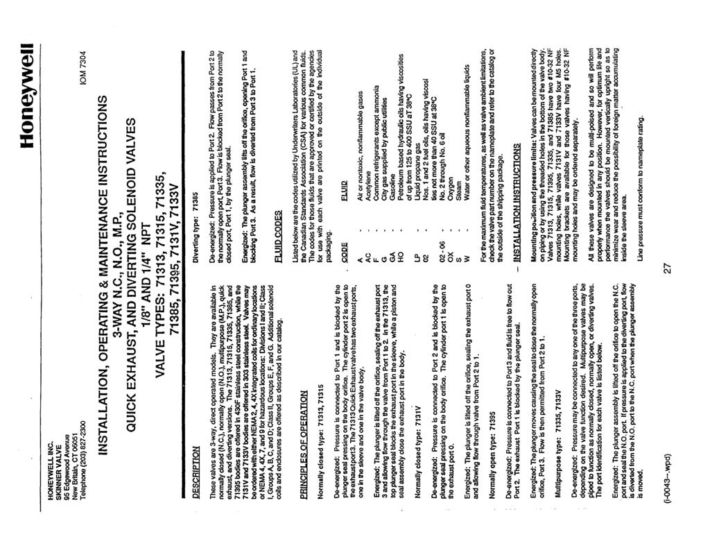
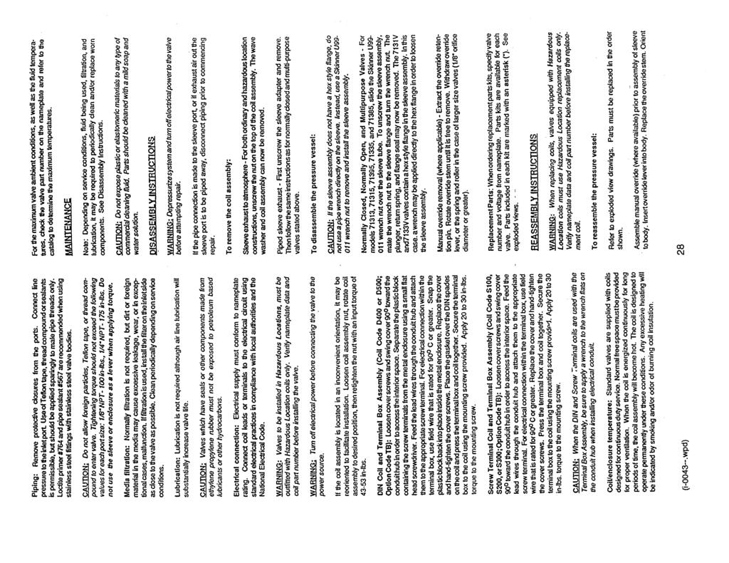
2 TABLE OF CONTENTS DESCRIPTION DWG.NO PAGE APPLICABL E I GENERAL SERVICE NOTES Y SP PILOT ASSEMBLY... APB Y / N SP PILOT RANGE TABLE... IB Y / N II TESTING AND CALIBRATION OF SP PILOT Y / N PRESSUREMATIC ASSEMBLY... APB Y / N III PRESSUREMATIC SET POINT ADJUSTMENT Y / N J-1 DIFFERENTIAL PRESSURE PILOT... A Y / N IV J-1 TEST PROCEDURE Y / N R324 REVERSING RELAY... C Y / N A424-HP 4-WAY RELAY... C Y / N DPS-2F DIFFERENTIAL PRESSURE SELECTOR ASSEMBLY... APB Y / N LPS-1 LOW PRESSURE SELECTOR VALVE ASSEMBLY... APB Y / N HPS-2 SHUTTLE VALVE... AP Y / N HPS-1 SELECTOR... APB Y / N MUFFLER Y / N C8A CHECK VALVE... AP Y / N CONANT SIGNAL SELECTOR Y / N DECAL, GAS / HYDRAULIC OPERATION, LP SELECTOR... SP Y / N MERCER RELIEF Y / N HONEYWELL THREE-WAY SOLENOID VALVE Y / N REXROTH SHUTTLE VALVE Y / N PRESSURE SWITCH (ES) Y / N GGTX-88 FILTER... C Y / N FD-1F V2 FILTER... C Y / N DD-1F DEHYDRATOR... C Y / N SJ31-B JUNCTION BOX... CB Y / N V NOTES Y / N (i wpd) 2
3 I GENERAL SERVICE NOTES Refer to applicable SCHEMATIC DRAWING(S). THE ITEMS BELOW WILL HAVE BEEN SUPPLIED IF SPECIFIED. The comments are applicable across the range of makes and models. ITEM COMPONENT 7 SPEED CONTROL VALVE A variable orifice which allows for independent control of opening and/or closing speed. 8 CHECK VALVE Permits flow in one direction only. 13 RELIEF Signal gas overpressure protection. 14 PILOT (HI AND LOW) Optional, if required, to switch signal gas depending on status of sensed pressure. Consult pilot bulletin for service and adjustments. 16 SIGNAL SELECTOR Typically to switch from automatic to manual operation for start-up etc. 19 JUNCTION BOX Provides additional terminals for wiring purposes. 20 SOLENOID VALVE(S) Converts electrical signal (E/P) (I/P) to pneumatic signal. See manufacturer's service bulletin at end of this manual. (i wpd) 3
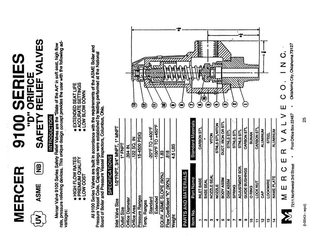
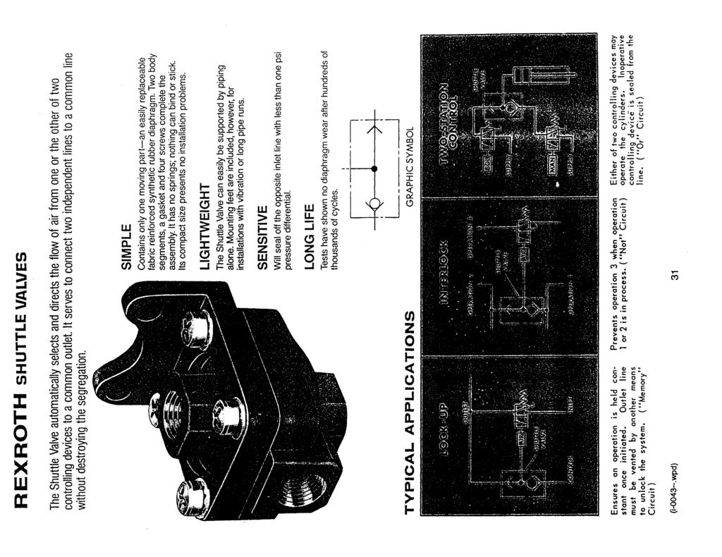
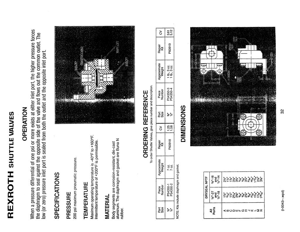
4 ... continued GENERAL SERVICE NOTES 22 VOLUME TANK Power gas storage for failsafe operation. Drain accumulated moisture and contaminants using pipe port provided. 23 RELIEF VALVE Supply gas overpressure protection. 25 REVERSING RELAY Bettis relay model (R324) N.O. relay. When reassembling, be careful to align body parts while bolts are just snug, before tightening completely. 27 PRESSURE SWITCH - static Converts pipeline pressure to an electrical signal to provide a low pressure power gas warning or desired position of the line valve. 29 PRESSURE SWITCH - differential Converts a pressure differential between two selected points to electrical signal. 30 PRESSURE SELECTOR VALVE Allow selection of "HIGH" and "LOW" signals for devices 31 PRESSURE SWITCH - static Monitors signal gas pressure. 32 DIFFERENTIAL PRESSURE PILOT Monitors differential pressure between two selected points; applies or removes a signal to operator control package. 35 SHUTTLE VALVE Common application of shuttle valve is "OR" circuit. Permits flow in one direction only. (i wpd) 4
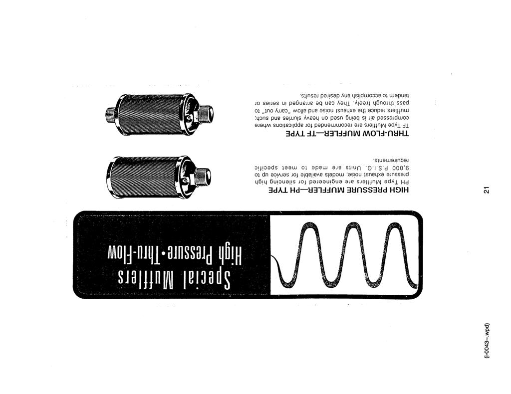
5 ... continued GENERAL SERVICE NOTES 36 LOW PRESSURE SELECTOR Selects the lower of two pressures for input to a device. 39 PRE FILTER Removes contaminants from supply gas. 79 PILOT (HI OR LOW) Monitors pressure at a point; applies or removes a signal to operator control package WAY 2-POSITION SWITCHING RELAY Reverses two signals. 85 MUFFLER Reduces exhaust noise. 94 MOLECULAR SIEVE DEHYDRATOR Removes water from instrument gas. (i wpd) 5
6
7
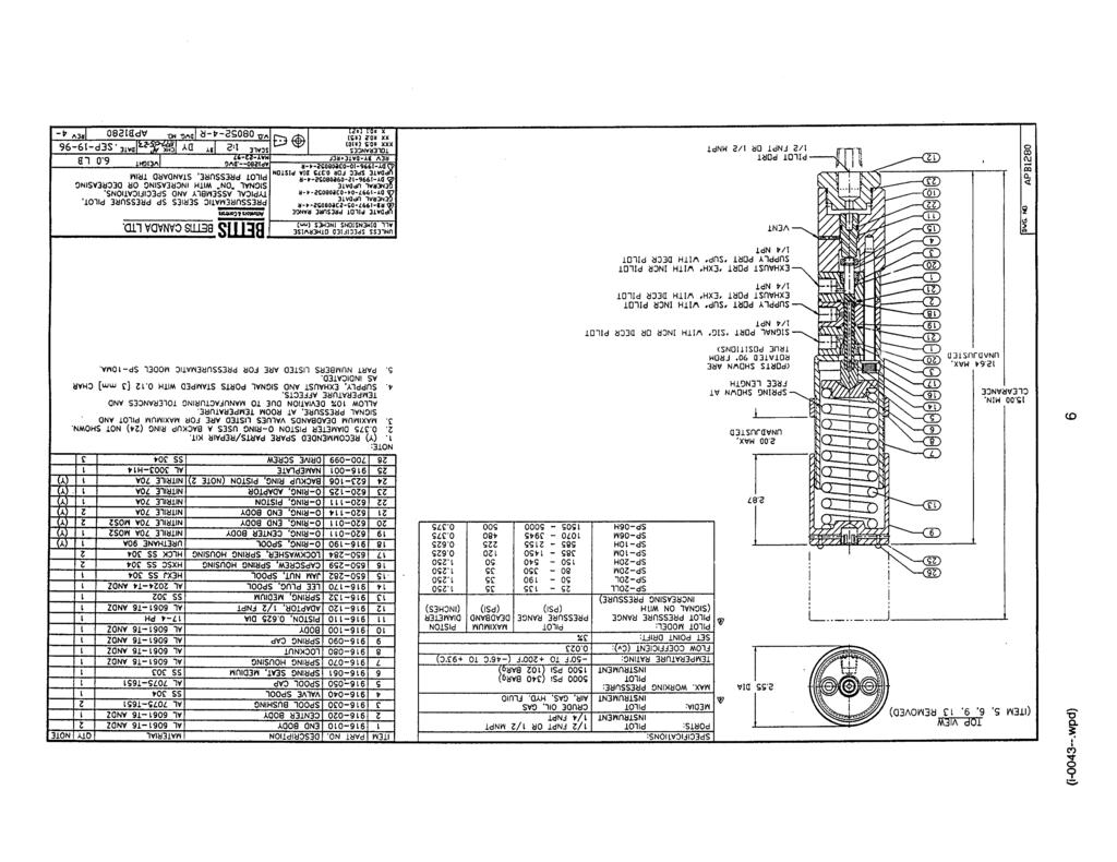
8 II TESTING AND CALIBRATION OF SP PILOT Refer to the typical assembly drawing on page 6. The SP pilot piston and spool must be cycle 20 times in order to seat the o-ring seals, prior to testing and calibration. A. PISTON LEAKAGE TEST 1. Apply 100 psig air to the 1/2 NPT pilot port connection and maintain for 1 minute. 2. Using Snoop, check for leakage at the vent port. No visible leakage is permitted. B. VALVE SPOOL LEAKAGE TEST 1. Apply 100 psig at the 1/4 NPT supply port connection on one end body (1) with the second end body (1) connection plugged, and maintain for 1 minute. 2. Using Snoop, check for leakage at the centre body (2) port, joints between body sections (1,2), and ends of body sections (1). No visible leakage permitted. C. PILOT CALIBRATION 1. Adjust the spring compression according to the calibration table on page 7. Interpolation may be used to estimate spring compression for intermediate set-points. 2. Apply 100 psig supply pressure at the 1/4 NPT supply port connection, stamped "SUP", via a closed isolation valve. 3. Apply required pilot pressure at the 1/2 NPT pilot port, on the adapter, via a pressure regulator and closed isolation valve. 4. Install and adequately rated pressure gauge at the 1/4 NPT signal port, stamped "SIG". 5. Open the supply and pilot isolation valves. a) For signal "ON" with increasing pilot pressure, using the pressure regulator, gradually increase pilot pressure at a rate of 20 psi/minute until signal pressure switches on. Record the actual set-point pressure. b) For signal "ON" with decreasing pressure, using the pressure regulator, gradually decrease pilot pressure at a rate of 20 psi/minute until signal pressure switches on. Record the actual set-point pressure. 6. Adjust the spring compression as required and repeat step 5, until the required set-point is reached. Hand tighten the locknut (8) to maintain set-point. 7. Stamp the nameplate (25) as required and mount on the spring cap (9). The complete designation per AP-1299 must be stamped on the nameplate. (i wpd) 8
9
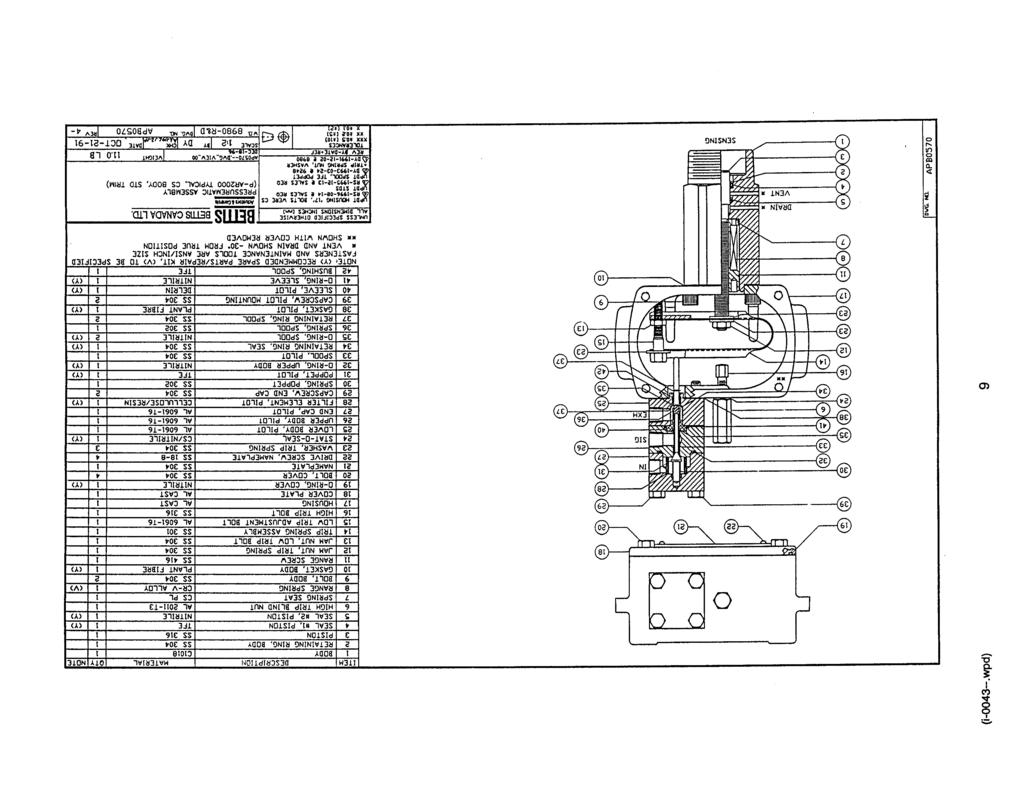
10 III PRESSUREMATIC SET POINT ADJUSTMENT; SERIES 2000, 2200, 2400 Refer to drawing APB0570 on page 8. This is done with the assembly complete and supply air on the pilot valve for P-AR and P-MR models. NOTE: In the field this requires a calibration kit able to supply high and low setpoint pressures (eg. nitrogen bottle with block & bleed valve). 1. Cases with low and high set points: THE LOW SET POINT MUST BE ADJUSTED FIRST. IT WILL NOT BE AFFECTED BY THE HIGH SET POINT ADJUSTMENT BUT, THE HIGH SET POINT IS AFFECTED WHEN THE LOW SET POINT IS ADJUSTED. a) Set the high trip bolt fully away from the trip spring. b) Repeatedly adjust the low trip bolt and decrease pressure through the low set point until the low trip occurs consistently at the low set point. Tighten the lock nut and recheck. Check that there is at least 0.02" piston travel from low trip to bottom stop. NOTE: When adjusting the low trip bolt, the upper arm of the trip spring must be pushed down. This unloads the bolt and allows it to be turned by hand. c) Repeatedly adjust the high trip bolt and increase pressure through the high set point until the high trip occurs consistently at the high set point. Tighten the lock nut and recheck. 2. Cases with low set point only: a) Set high trip bolt fully away from the trip spring. b) Adjust the low set point as described in item 1.b) above. c) To disable high trip: Increase pressure until the piston is at the upper stop. Adjust high trip bolt downward until high trip occurs, then retract 1/2 turn. Check that high trip does not occur when the piston travels to the upper stop. This high trip bolt adjustment is to prevent the trip spring from placing unnecessary force on the spool. (i wpd) 10
11
12
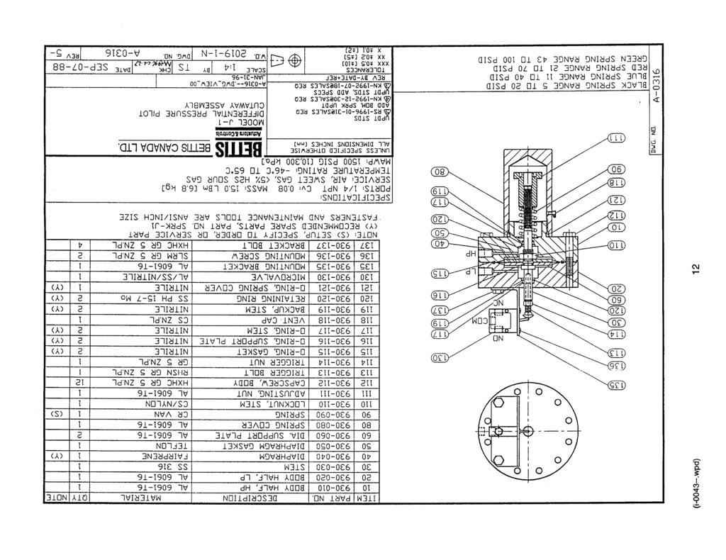
13 IV J-1 TEST PROCEDURE Following is: High Pressure Test, Leak/Blowby Test, Microvalve Alignment, and Calibration Check for correct port designations... H.. HIGH SIDE, L.. LOW SIDE, as per drawing A. HIGH PRESSURE TEST Without microvalve installed or if it is installed, adjust trigger bolt fully into stem so that over travel damage will not occur to microvalve. Remove spring cover, adjust nut, and range spring. H..port connect a regulated 1500 psi supply, and apply pressure in 100 psi increments checking for leaks at diaphragm, stem seals, and blowby at.. L.. port. Maintain the 1500 psi on H.. port and apply 100 psi supply to microvalve supply port for alignment following. B. ALIGNMENT OF MICROVALVE With supply pressure connected as above; 1. adjust trigger bolt until microvalve is fully triggered, signal is vented, and lock bolt in place with locking nut. 2. check for over travel allowance of microvalve lever should be 0.010" to 0.032" away from trigger bolt. CAUTION: DO NOT FORCE LEVER AWAY FROM BOLT WITH MUCH FORCE. MICROVALVE SHOULD BE ALIGNED FOR PROPER OPERATION 1. reduce H.. port supply to zero. 2. L.. port connect a second regulated supply of 1500 psi and apply in 100 psi increments 1500 psi to L.. port. Checking for leaks at diaphragm and stem seals. 3. Reduce L.. port supply to zero. Disconnect supply so that L.. will be at atmospheric pressure for calibration following. (i wpd) 13
14 ... continued J-1 TEST PROCEDURE C. CALIBRATION PROCEDURE From range spring chart select proper range spring, record color code; spring O.D. and length on test check sheet. 1. Install range spring and adjust adjusting nut to hold the spring loosely in place. This can be your ZERO TURN POINT. 2. Apply pressure slowly to H.. port until unit trips. Note pressure on supply gauge, this is the differential pressure across the diaphragm of the J Reduce pressure to zero, adjust range spring preload... increase spring tension for higher differential pressure... decrease spring tension for lower differential pressure D. OPERATIONAL TEST Apply 600 psi then 900 psi to both port H.. and L.. at same time. Block and vent L.. supply slowly while maintaining H.. supply. When J-1 unit triggers note readings of H.. supply gauge and L.. supply gauge. The diff. should be calibrated differential pressure setting. Remove H.. supply, check for blowby by applying 1500 psi to L.. (i wpd) 14
15
16
17
18
19
20
21
22
23
24
25
26
27
28
29
30
31
32
33
34
35
36
37
38
39
40
41
42 V NOTES (i wpd/42 orig:db rev5:ap/ps app dist:(ef)o);(sm)p)
BETTIS J1-RT2 RATE OF DROP LINEBREAK DETECTION SYSTEM. FACTORY SET: psi/min psi P/L
 Bettis Canada Ltd. 4112 91A Street Edmonton, Alberta, Canada T6E 5V2 Tel: (780) 450-3600 EDMONTON Fax: (780) 450-1400 Service Manual BETTIS J1-RT2 RATE OF DROP LINEBREAK DETECTION SYSTEM CUSTOMER: P.O.#:
INSTALLATION INSTRUCTIONS. CVS 67CFR Pressure Reducing Instrument Supply Regulator INTRODUCTION
 INSTALLATION INSTRUCTIONS CVS 67CFR Pressure Reducing Instrument Supply Regulator INTRODUCTION The CVS Controls 67CFR Filter regulator is a pressure reducing supply regulator typically used for pneumatic
ACCUMULATOR OPERATING & MAINTENANCE INSTRUCTIONS
 ACCUMULATOR OPERATING & MAINTENANCE INSTRUCTIONS READ ALL INSTRUCTIONS PRIOR TO INSTALLATION AND OPERATION TO AVOID POSSIBLE INJURY Warning: Always consider any accumulator to contain pressure until proven
Discontinued. Powers Controls. Technical Instructions Document No P25 RV Rev. 1, May, RV 201 Pressure Reducing Valves.
 Powers Controls RV 201 Pressure Reducing Valves Description Features Product Numbers Dual Pressure PRV Technical Instructions Document No. 155-049P25 RV 201-1 Single Pressure PRV The RV 201 Pressure Reducing
Gas Hydraulic Valve Operator
 A L o ng E xper ience in Energy Equipmen t and One G o al: T he C u sto mer s Sa tisfa c tion Gas Hydraulic Valve Operator Rugged, reliable controls are at the heart of any good actuator. In the pipeline
64 Series Pressure Reducing Regulators
 Instruction Manual Form 1245 64 Series March 2006 64 Series Pressure Reducing Regulators W1943 Figure 1. 64 Series Regulator Introduction Scope of Manual This manual provides instructions for the installation,
Type S301 & S302 Gas Regulators INTRODUCTION INSTALLATION. Scope of Manual. Description. Specifications. Type S301 and S302. Instruction Manual
 Fisher Controls Instruction Manual Type S301 & S302 Gas Regulators October 1981 Form 5180 WARNING Fisher regulators must be installed, operated, and maintained in accordance with federal, state, and local
299H Series. Introduction. P.E.D. Categories. Specifications. Installation. Warning. Installation Guide English September 2012
 Installation Guide English September 2012 299H Series Introduction This Installation Guide provides instructions for installation, startup, and adjustment of 299H Series regulators. To receive a copy of
Type ACE97. Introduction. Installation. P.E.D. Categories. Specifications. Overpressure Protection. Installation Guide English May 2002
 Installation Guide English May 2002 Type ACE97 Introduction This installation guide provides instructions for installation, startup, and adjustment. To receive a copy of the instruction manual, contact
TECHNICAL DATA. Page 1 of 12
 Page 1 of 12 1. DESCRIPTION The Viking Regulating Valve is a direct-acting, single-seated, spring-loaded diaphragm valve. When installed as a pilot regulating valve on a Viking Model H or J Flow Control
Anderson Greenwood Series 400 Diaphragm Pilot Operated Safety Relief Valves. Installation and Maintenance Instructions for
 Before installation these instructions must be fully read and understood The main valve uses the principle of pressurizing the top or large area of a differential area piston with line pressure to hold
INSTRUCTION MANUAL. CVS P37 LP Gas Reducing Regulator
 INSTRUCTION MANUAL CVS P37 LP Gas Reducing Regulator The CVS Controls P37 Regulator is a non-relieving, pressure reducing regulator suitable for use in LP gas applications (Natural Gas and Propane). As
TECHNICAL DATA. Pressure Regulation 531a. April 24, 2009
 April 24, 29 Pressure Regulation 531a 1. DESCRIPTION The Viking Regulating Valve is a direct-acting, single-seated, spring-loaded diaphragm valve. When installed as a pilot regulating valve on a Viking
Welker Sampler. Model GSS-1. Installation, Operation, and Maintenance Manual
 Installation, Operation, and Maintenance Manual Welker Sampler Model GSS-1 The information in this manual has been carefully checked for accuracy and is intended to be used as a guide to operations. Correct
TECHNICAL DATA CAUTION
 Page 1 of 12 1. DESCRIPTION The Viking Model C-2 Pilot Pressure Regulating Valve is a direct-acting, single-seated, spring-loaded diaphragm valve. When installed as a pilot regulating valve on a Viking
Powers Controls D Day-Night Thermostats
 Powers Controls D Day-Night Thermostats Technical Instructions Document No. 155-073P25 TH 832-2 Description The D Day-Night or Two Temperature Thermostat is available as a room-type instrument. It is essentially
Installation, Operation and Maintenance Manual for Back Pressure Regulator
 Installation, Operation and Maintenance Manual for Back Pressure Regulator Model 8860 2009 Groth Corporation IOM-8860 Rev. B 12541 Ref. ID: 95565 Page 2 of 13 Table of Contents I. INTRODUCTION 3 II. DESIGN
Types S100K and S102K Pressure Regulators
 Instruction Manual Form 5624 Types S0K and S2K 01/01 Types S0K and S2K Pressure Regulators W7478-1 Figure 1. Types S0K and S2K Pressure Regulator Introduction Scope of Manual This manual provides instructions
Product Manual. Description. Specifications. CVS Type 1301F and CVS Type 1301G Regulator. Introduction
 Product Manual CVS Type 1301F and CVS Type 1301G Regulator Introduction This CVS Controls product manual includes instructions for the installation, adjustment, maintenance and parts ordering of the CVS
Manual Actuated Boiler Blowdown Valves
 Manual Actuated Boiler Blowdown Valves Installation and Maintenance Instructions 1. Safety information 2. General product information 3. Installation 4. Operation 5. Maintenance 6. Spare parts p.1 1. Safety
MEGR-1627 Instruction Manual
 MEGR-1627 HIGH FLOW GAS REGULATOR Instruction Manual- Look Inside For: Description Installation Remote Vent Line Installations Startup and Adjustment Shutdown Maintenance Body Maintenance Procedures Diaphragm
P5513. Users Manual. Pneumatic Comparison Test Pump. Test Equipment Depot Washington Street Melrose, MA TestEquipmentDepot.
 Test Equipment Depot - 800.517.8431-99 Washington Street Melrose, MA 02176 TestEquipmentDepot.com P5513 Pneumatic Comparison Test Pump Users Manual PN 3963372 November 2010 2010 Fluke Corporation. All
Float Operated Level Controllers
 CONTENTS Float Operated Level Controllers IM0015 Nov. 2014 PAGE Introduction 1 Scope 1 Description 1 Specification 1 Control Installation 2 INTRODUCTION Side Mount Back Mount Prior to installing, the instructions
OPERATION MANUAL NTF-60 Plus
 OPERATION MANUAL NTF-60 Plus Nitrogen Tire Filling Valve Stem Caps (Qty=200) Order P/N 436075 RTI Technologies, Inc 10 Innovation Drive York, PA 17402 800-468-2321 www.rtitech.com 035-81264-00 (Rev A)
OPERATION MANUAL NTF-15
 OPERATION MANUAL NTF-15 Nitrogen Tire Filling Valve Stem Caps (Qty=200) Order P/N 436075 RTI Technologies, Inc 10 Innovation Drive York, PA 17402 800-468-2321 www.rtitech.com 035-81235-00 (Rev B) TABLE
Type HSR Pressure Reducing Regulator for Residential, Commercial, or Industrial Applications
 Instruction Manual Form 5753 Type HSR October 2003 Type HSR Pressure Reducing Regulator for Residential, Commercial, or Industrial Applications W8648 Figure 1. Type HSR Pressure Regulator Introduction
RC 195 Receiver-Controller
 Document No. 129-082 RC 195 Receiver-Controller Product Description The POWERS RC 195 Receiver-Controller is a pneumatic instrument that receives one, two or three pneumatic inputs. It produces a pneumatic
Types S108K and S109K Pressure Reducing Regulators with Integral Slam-Shut Device
 Instruction Manual Form 5492 Types S108K and S109K May 1999 Types S108K and S109K Pressure Reducing Regulators with Integral Slam-Shut Device Introduction Fisher regulators must be installed, operated
Smooth Vent Valve. Series XVD XL XL Q D- XVD XGT CYV
 Smooth Vent Valve Series Valve / needle valve integrated construction requires only 1/4 the piping space of previous models. Particulates significantly reduced through the use of a metal diaphragm in the
DS05C,D,G Dial Set Pressure Regulating Valves
 DS05C,D,G Dial Set Pressure Regulating Valves APPLICATION The Honeywell DS05C,D,G Dial Set Pressure Regulating Valve is a high quality pressure regulating valve that maintains a constant outlet pressure
TECHNICAL DATA. Q = C v P S
 Page 1 of 13 1. DESCRIPTION The Viking 6 Model G-6000 Dry Valve Riser Assembly consists of a small profile, light weight, pilot operated valve that is used to separate the water supply from the dry sprinkler
Pressure and/or Temperature Pilot Operated Steam Regulators Series 2000
 Hoffman Specialty Regulators Regulators Pressure and/or Temperature Operated Regulators Series 2000 The Hoffman Specialty Series 2000 consists of main valves, pilot valves, wells and hardware kits. They
Anderson Greenwood Series 93 Positive Pressure POSRV Installation and Maintenance Instructions
 Before installation these instructions must be fully read and understood Installation and maintenance instructions for Series 93 Positive Pressure Pilot Operated Safety Relief Valves (POSRV). The intent
Model: 720-UL INSTALLATION OPERATION MAINTENANCE. Bermad Pressure Reducing Valve IOM. Model: FP -720-UL Sizes: 2"-12" BERMAD. Application Engineering
 Bermad Pressure Reducing Valve Model: 720-UL INSTALLATION OPERATION MAINTENANCE Application Engineering BERMAD 1. Safety First BERMAD believes that the safety of personnel working with and around our equipment
OPERATING AND MAINTENANCE MANUAL
 Series 4300 Engineered Performance TABLE OF CONTENTS 0 INTRODUCTION 1 1 Scope 1 2 Description 1 3 Specifications 1 0 INSTALLATION 1 1 Mounting 1 2 Piping 1 1 Connecting Process Pressure 2 2 Vent Connections
The Ins and Outs of I/P Transducers
 The Ins and Outs of I/P Transducers By Mark B. Levine, ControlAir Inc. General description I/P transducers are versatile instruments that use an electrical control signal to proportionally regulate gas
1305 Series Pressure Reducing Regulators
 Instruction Manual Form 1095 1305 Series October 2009 1305 Series Pressure Reducing Regulators! Warning Fisher regulators must be installed, operated, and maintained in accordance with federal, state,
CSC-2000 SERIES. Reset Volume Controllers MADE IN U.S.A. DESCRIPTION MODELS SPECIFICATIONS ORDERING
 CSC-2000 SERIES Reset Volume Controllers MADE IN U.S.A. DESCRIPTION The CSC-2000 series are designed for use on VAV terminal units in HVAC systems. These are submaster air velocity controllers whose velocity
RHPS Series RD(H)F40 User Manual. Read the complete manual before installing and using the regulator.
F40 User Manual. Read the complete manual before installing and using the regulator.") RHPS Series RD(H)F40 User Manual Read the complete manual before installing and using the regulator. 2 WARNING Before removing a regulator from the system for service, you must depressurize system purge
RHPS Series RD(H)F40 User Manual Read the complete manual before installing and using the regulator. 2 WARNING Before removing a regulator from the system for service, you must depressurize system purge
SERIES 500 VARIABLE RANGE PNEUMATIC DIFFERENTIAL PRESSURE TRANSMITTER
 Man500e 09/2006 Installation Operation and Maintenance Instructions SERIES 500 VARIABLE RANGE PNEUMATIC DIFFERENTIAL PRESSURE TRANSMITTER INDEX 1. INSTALLATION 2. COMPRESSED AIR SUPPLY 3. FLOW MEASURE
Oxygen Usage Best Practice Guide
 Oxygen Usage Best Practice Guide 1. Introduction Oxygen enriched systems possess a risk of fire and explosion since ignition and combustion hazards are present in all oxygen systems, and oxygen related
1805 Series Relief Valves
 Instruction Manual Form 1211 1805 Series October 2011 1805 Series Relief Valves! WARNING Failure to follow these instructions or to properly install and maintain this equipment could result in an explosion
C645A-E Pressure Switches
 C645A-E Switches FEATURES PRODUCT DATA C645A,B,D,E GENERAL C645A,B with Window C645C The C645 pressure switches are safety devices used in positive-pressure or differential-pressure systems to sense gas
Type FL Pressure Reducing Regulators
 Instruction Manual D103068X01 August 018 Pressure Reducing Regulators! Warning Failure to follow these instructions or to properly install and maintain this equipment could result in an explosion and/or
Installation Operation Maintenance. Bermad Level Control Valve with Modulating Horizontal Float Pilot valve One Way Flow IOM.
 Bermad Level Control Valve with Modulating Horizontal Float Pilot valve One Way Flow Model: FP 450-80 Installation Operation Maintenance PAGE 1 OF 5 1. Safety First BERMAD believes that the safety of personnel
1200B2 Series Service Regulators. Instruction Manual
 00B Series Service Regulators Instruction Manual 00B Series Service Regulators 0 Elster American Meter 00B Series Service Regulators General Information The 00B Series Service Regulators are available
TECHNICAL DATA 3 MODEL G-3000 DRY VALVE RISER ASSEMBLY
 Page 1 of 13 1. DESCRIPTION The Viking 3 Model G-3000 Dry Valve Riser Assembly is equipped with a small profile, light weight, pilot operated valve that is used to separate the water supply from the dry
Pressure Dump Valve Service Kit for Series 2300 Units
 Instruction Sheet Pressure Dump Valve Service Kit for Series 00 Units. Overview The Nordson pressure dump valve is used to relieve hydraulic pressure instantly in Series 00 applicator tanks when the unit
Smooth Vent Valve XVD. Series
 Smooth Vent Valve Series Valve / needle valve integrated construction requires only 1/4 the piping space of previous models. Particulates significantly reduced through the use of a metal diaphragm in the
WW-730. Pressure Sustaining/Relief Control Valve
 WW-730 Pressure Sustaining/Relief Control Valve Installation Operation & Maintenance Page 1 of 6 1. DESCRIPTION The Model 730 Pressure Relief / Sustaining Valve is an automatic control valve designed to
TECHNICAL DATA. Q= Cv S
 Page 1 of 13 1. DESCRIPTION The Viking 4 inch Model G-4000 Dry Valve Riser Assembly consists of a small profile, light weight, pilot operated valve that is used to separate the water supply from the dry
TECHNICAL DATA Q = C. v P S. 2 Model G-2000 Dry valve. Page 1 of 13
 Page 1 of 13 1. Description The Viking 2 Model G-2000 Dry Valve Riser Assembly consists of a small profile, light weight, pilot operated valve that is used to separate the water supply from the dry sprinkler
NGP-250/500 Nitrogen Generator Quick Start Guide
 NGP-250/500 Nitrogen Generator Quick Start Guide Version: A July 2013 Potter Electric Signal Company, LLC 5757 Phantom Dr., Suite 125 P. O. Box 42037 Hazelwood, MO 63042 Phone: (314) 595-6900 Document
299H Series Pressure Reducing Regulators
 Instruction Manual Form 5497 299H Series January 2014 299H Series Pressure Reducing Regulators! WARNING Failure to follow these instructions or to properly install and maintain this equipment could result
CSC-2000 SERIES. Reset Volume Controllers MADE IN U.S.A. DESCRIPTION MODELS SPECIFICATIONS ORDERING
 CSC-2000 SERIES Reset Volume Controllers MADE IN U.S.A. DESCRIPTION The CSC-2000 series are designed for use on VAV terminal units in HVAC systems. These are submaster air velocity controllers whose velocity
Operation & Maintenance Manual Place this manual with valve or person responsible for maintenance of the valve
 Operation & Maintenance Manual Place this manual with valve or person responsible for maintenance of the valve Model CYCLE GARD II, CI & CNA YOUR PRODUCT INFORMATION: Model Number: Date: Serial Number:
V DGX Series. Direct-Operated Regulators Manual D103834X012
 V2015.3 DGX Series Direct-Operated Regulators Manual D103834X012 Contents 1. Introduction... 3 2. Specifications... 3 3. Features... 3 4. Dimensions... 4 5. Principle of Operation... 5 6. Performance Curves...
FOR INSTALLING CO 2 BLENDER KIT (P/N IN BEER SYSTEM
 IMI CORNELIUS INC One Cornelius Place Anoka, MN 55303-623 Telephone (800) 238-3600 Facsimile (612) 22-326 INSTALLATION INSTRUCTIONS FOR INSTALLING CO 2 BLENDER KIT (P/N 111612000 IN BEER SYSTEM SECONDARY
Smooth Vent Valve. XVD Series
 Smooth Vent Valve Series Valve / needle valve integrated construction requires only 1/4 the piping space of previous models. Particulates significantly reduced through the use of a metal diaphragm in the
TECHNICAL DATA MAINTENANCE AIR COMPRESSOR MODEL G-1
 Dry 131h 1. DESCRIPTION The Viking Model G-1 Maintenance Air Compressor is an electric motor-driven, aircooled, single-stage, oil-less compressor. The unit is equipped with a check valve and provides a
Operation Manual. Diaphragm Sensed Gas Pressure Regulators
 687 Technology Way Napa, CA 94558 Phone: (707) 259-0102 FAX: (707) 259-0117 www.aptech-online.com Diaphragm Sensed Gas (AP/AZ/AK Models: 20, 100, 500, 1000, 1000T 10PA, 1100, 1200, 12PA, 1300, 1400T, 14PA,
Installation, Operation, and Maintenance Manual
 Installation, Operation, and Maintenance Manual Welker Instrument Supply Pressure System Model WIC The information in this manual has been carefully checked for accuracy and is intended to be used as a
Operation & Service Manual
 Operation & Service Manual Model: 20-4505-7000 Four Bottle Oxygen Cart with Booster CAUTION! It is mandatory that this instruction manual be read and understood by all persons operating this high pressure
Pressure Dump Valve Service Kit for Series 3000 Units
 Instruction Sheet Pressure Dump Valve Service Kit for Series 000 Units. Overview The Nordson pressure dump valve is used to relieve hydraulic pressure instantly in Series 00, 400, 500, and 700 applicator
FLUID POWER FLUID POWER EQUIPMENT TUTORIAL ACCUMULATORS. This work covers part of outcome 2 of the Edexcel standard module:
 FLUID POWER FLUID POWER EQUIPMENT TUTORIAL ACCUMULATORS This work covers part of outcome 2 of the Edexcel standard module: UNIT 21746P APPLIED PNEUMATICS AND HYDRAULICS The material needed for outcome
Operation Manual Piston Sensed Gas Pressure Regulators
 687 Technology Way Napa, CA 94558 Phone: (707) 259-0102 FAX: (707) 259-0117 www.aptech-online.com Operation Manual Piston Sensed Gas Pressure Regulators (Models KT9, KT10, Welded KT10, KT12) Table of Contents:
2.0 INSTALLATION & SERVICE
 Installation, Operation, and Maintenance Instructions MODEL 5600 / 5600R January 2005 CONTENTS 1.0 GENERAL 1.1 5600 Model Number Information -----------------------------------------------------------------------
Type ACE95jr Tank Blanketing Valve
 Instruction Manual Form 5666 Type ACE95jr 04/01 Type ACE95jr Tank Blanketing Valve W8157 Introduction Scope of Manual Figure 1. Type ACE95jr Tank Blanketing Valve This instruction manual provides installation,
Pneumatics. ZF Marine Pneumatics
 St. Louis, MO 3137 Phone: 1-800-381-998 ZF Marine Designed for vessels with reverse reduction gears and diesel engines in the higher horsepower range, the ZF Marine Electronics AD12 pneumatic control systems,
Mounting and Operating Instructions EB 8546 EN. Supply Pressure Regulator Type Fig. 1 Supply pressure regulators
 Supply Pressure Regulator Type 4708 Type 4708-5352 on Type 3730 Positioner Type 4708-52 with filter receptacle Type 4708-6252 on Type 3372 ctuator Fig. Supply pressure regulators Mounting and Operating
Pressure on Demand. Air Pressure Amplifiers
 Pressure on Demand Air Pressure Amplifiers Introduction Haskel air pressure amplifiers offer the most comprehensive range in the industry combining simple principles of operation with rugged construction
TECHNICAL DATA OBSOLETE
 January 11, 2007 Dry 122a PRODUCT DESCRIPTION The Viking Model E-1 Accelerator is a quick-opening device. When installed with the required external Anti-fl ood Device, the assembly is designed to increase
Components for air preparation and pressure adjustment. OUT port position ( ) connected Rear side. of IN port. Air tank. directly.
 connected Rear side. of IN port. Air tank. directly.") Components preparation and pressure adjustment ABP Overview ABP is a component that enables boosting by s only up to twice primary pressure (.0MPa max.) in combination with using air tank but not using
Components preparation and pressure adjustment ABP Overview ABP is a component that enables boosting by s only up to twice primary pressure (.0MPa max.) in combination with using air tank but not using
Pressure Sensing Valve - Model 4023
 Pressure Sensing Valve - Model 4023 Overview AMOT Model 4023 can be used as a 2 or 3-way capacity, pressure sensing valve. This valve is ideal for applications that require compressor suction and discharge
DUAL 444C ONBOARD AIR SYSTEM
 DUAL 444C ONBOARD AIR SYSTEM PART NO. 20019 IMPORTANT: It is essential that you and any other operator of this product read and understand the contents of this manual before installing and using this product.
Unit 24: Applications of Pneumatics and Hydraulics
 Unit 24: Applications of Pneumatics and Hydraulics Unit code: J/601/1496 QCF level: 4 Credit value: 15 OUTCOME 2 TUTORIAL 9 ACCUMULATORS The material needed for outcome 2 is very extensive so there are
SALCO PRODUCTS, INC. PRESSURE RELIEF VALVE STORAGE, INSTALLATION, OPERATING, MAINTENANCE/TESTING, AND INSPECTION INSTRUCTIONS
 STORAGE INSTRUCTIONS Until it is time to install a new or reconditioned valve on the car, the valve must be kept in its original packaging in order to protect it from dirt and damage. INSTALLATION INSTRUCTIONS
Operation Manual - PN A MENSOR MODEL 73 SHOP AIR BOOSTER
 Operation Manual - PN 0017946001 A MENSOR MODEL 73 SHOP AIR BOOSTER Mensor Model 73 Shop Air Booster System (750 psi Version) April 23, 2012 Trademarks / Copyright Mensor is a registered trademark of Mensor
KBV21i and KBV40i Key Operated Boiler Blowdown Valves Installation and Maintenance Instructions
 4059051/3 IM-P405-48 EMM Issue 3 KBV21i and KBV40i Key Operated Boiler Blowdown Valves Installation and Maintenance Instructions 1. Safety information 2. General product information 3. Installation 4.
Anti-flood device Model B-1
 December 4, 2009 Dry Systems 123a 1. DESCRIPTION The Anti-flood Device is required when Viking accelerators are installed on dry systems according to Viking Model E-1 Accelerator Trim Charts. In the SET
BCV31 DN40 - Blowdown Control Valve
 4034850/5 IM-P403-71 AB Issue 5 BCV31 DN40 - Blowdown Control Valve Installation and Maintenance Instructions 1. Safety information 2. Application 3. Technical data 4. Operation 5. Installation 6. Flow
PRO-50 Instrument Supply Regulator
 Features CRN Approved The PRO-50 Regulator has been granted a Canadian Registration Number. Sour Service Capability Available in NACE configurations that comply with NACE MR0175/MR0103. Environmental limits
Type R622 Pressure Reducing Regulator
 Type R622 Pressure Reducing Regulator June 2010 Compact Design Protective Inlet Screen High Capacity Internal Relief Light Weight W8806 Inlet and Outlet Pressure Gauge Taps Figure 1. Type R622 Pressure
PVQ 13 A2 R SE 1 S 20 C-11 D
 PVQ - Variable Displacement Piston Pump PVQ 13 A2 R SE 1 S 2 C-11 D 1 2 3 4 6 7 8 9 1 1 Model Series PVQ Inline Piston Pump Variable Volume Quiet Series 4 Rotation Viewed from shaft end R Right hand, standard
D05 Pressure Regulating Valves
 D05 Pressure Regulating Valves FEATURES PRODUCT DATA Noncorroding unitized cartridge contains all working parts and is easily replaceable. Includes built-in strainer and thermal bypass. Balanced seat construction
RB Series Regulating System
 RB Series Instruction Manual Form 5872 January 2010 RB Series Regulating System filtration module RegulatoR module Box connecting Bolt outlet Ball valve inlet Ball valve Figure 1. RB Series Regulating
LRS(H)4 Pressure-Reducing Regulator User Manual
4 Pressure-Reducing Regulator User Manual") LRS(H)4 Pressure-Reducing Regulator User Manual Read the complete manual before installing and using the regulator. 2 Safe Product Selection When selecting a product, the total system design must be considered
LRS(H)4 Pressure-Reducing Regulator User Manual Read the complete manual before installing and using the regulator. 2 Safe Product Selection When selecting a product, the total system design must be considered
Mooney* FlowMax* Regulator
 GE Oil & Gas Mooney* FlowMax* Regulator Instruction Manual (Rev. A) GE Data Classification : Public THESE INSTRUCTIONS PROVIDE THE CUSTOMER/OPERATOR WITH IMPORTANT PROJECT- SPECIFIC REFERENCE INFORMATION
Hydraulic Piston Accumulators
 Ride Control Engineering Services PWCE Extendavator Paul Wever Construction Equipment Co., Inc. P.O. Box 85 401 Martin Drive Goodfield, IL 61742-0085 Phone (309) 965-2005 Fax (309) 965-2905 1-800-990-PWCE
1800C and 1800C-HC Series Service Regulators
 1800C and 1800C-HC Series Service Regulators Installation Instructions www.elster-americanmeter.com General Information: The 1800C and 1800C-HC Regulators are available as Full Capacity Internal Relief
Hi-Force Limited Prospect Way Daventry Northants NN11 8PL United Kingdom Tel: +44(0) : Fax: +44(0) : Website:
 : Fax: +44(0) : Website:") 1.0 Inspection of the product upon receipt: On receipt of the product, visually inspect the item for any evidence of shipping damage. Please note shipping damage is not covered by warranty. If shipping
1.0 Inspection of the product upon receipt: On receipt of the product, visually inspect the item for any evidence of shipping damage. Please note shipping damage is not covered by warranty. If shipping
MADILL 24.7" 365 TILT SET-UP PROCEDURE WITH REXROTH VALVE ON MACHINE
 MADILL 24.7" 365 TILT SET-UP PROCEDURE WITH REXROTH VALVE ON MACHINE MADILL 24.7" SAW - 365 DEG. TILT-REXROTH VALVE DANGER DO NOT perform any adjustment on sawhead unless saw blade lock bolt and guard
Adjustable. Unloader Valve. O&M Manual. Part #
 Adjustable Unloader Valve O&M Manual Unloader Valve Part #60-020-361 ADVANCED PRESSURE SYSTEMS 701 S. Persimmon St., Suite 85 - Tomball, TX 77375 Toll Free in North America: (877) 290-4277 Phone: (281)
Types 749B and R130 Changeover Manifolds
 Instruction Manual MCK-1179 Types 749B and R130 June 2012 Types 749B and R130 Changeover Manifolds TYPE HSRL-749B TYPE 64SR/122 TYPE R130/21 TYPE 749B/21 Figure 1. Changeover Manifolds and Regulator Assemblies
SIX R (P ) AND SEVEN R (P ) POSITION CYLINDERS Service Information
 AND SEVEN R (P ) POSITION CYLINDERS Service Information") SIX R431006322 (P -063892-00001) AND SEVEN R431006321 (P -063981--00002) POSITION CYLINDERS Service Information The six and seven position cylinders are medium duty pneumatic positioning devices that operate
SIX R431006322 (P -063892-00001) AND SEVEN R431006321 (P -063981--00002) POSITION CYLINDERS Service Information The six and seven position cylinders are medium duty pneumatic positioning devices that operate
Bray/ VAAS O-Ported Series Knife Gate Valve 770/780 Series Operation and Maintenance Manual
 Bray/ VAAS Knife Gate Valve 770/780 Series Operations and Maintenance Manual Table of Contents Definition of Terms 1 Safety Instructions 1 Introduction 2 Unpacking 2 Storage 2 Installation 2 Commissioning
DS06D,G Dial Set Pressure Regulating Valve
 DS06D,G Dial Set Pressure Regulating Valve PRODUCT DATA FEATURES APPLICATION Built-in, factory-calibrated outlet pressure adjustment dial. Noncorroding unitized cartridge contains all working parts and
Type CT88 Backpressure Regulator
 Instruction Manual Type CT88 July 2016 Type CT88 Backpressure Regulator Table of Contents Introduction...1 Specifications...2 Principle of Operation...2 Installation...3 Overpressure Protection...4 Startup...4
RD(H)20/25 Pressure-Reducing Regulator User Manual
20/25 Pressure-Reducing Regulator User Manual") RD(H)20/25 Pressure-Reducing Regulator User Manual Read the complete manual before installing and using the regulator. 2 Safe Product Selection When selecting a product, the total system design must be
RD(H)20/25 Pressure-Reducing Regulator User Manual Read the complete manual before installing and using the regulator. 2 Safe Product Selection When selecting a product, the total system design must be
Power Valve: Precision Regulator. High precision, large capacity relief regulator
 Power Valve: Precision Regulator Series VEX High precision, large capacity relief regulator port large exhaust capacity pressure reducing valve which utilizes a nozzle flapper mechanism available as air