Investigating Fluid Flow Phenomena behind Intersecting and Tapered Cylinders using submerged Stereoscopic PIV
|
|
|
- Mabel Wilkinson
- 6 years ago
- Views:
Transcription
1 Investigating Fluid Flow Phenomena behind Intersecting and Tapered Cylinders using submerged Stereoscopic PIV Chittiappa Muthanna 1, Jan Visscher 2, Bjørnar Pettersen 3 1: Offshore Hydrodynamics, MARINTEK, Trondheim, Norway: chittiappa.muthanna@marintek.sintef.no 2: Dept. of Marine Technology, NTNU, Trondheim, Norway: jan.h.visscher@ntnu.no 3: Dept. of Marine Technology, NTNU, Trondheim, Norway: bjornar@ntnu.no Abstract Particle Image Velocimetry (PIV) has been successfully utilized in a towing tank facility to measure the fluid field behind a grid of intersecting cylinders, and behind a tapered cylinder. The study was also performed to ascertain the feasibility and applicability of using the Stereoscopic PIV technique in towing tanks, as the setup is now submerged underwater thereby limiting access to the optics once the measurement program is underway, as well as introducing complications to seeding and calibration methods. The primary challenges encountered were ensuring accurate alignment of the optics once the system is submerged, successfully seeding the area of interest in such large volumes of water, and calibrating the system accurately underwater. Results from the PIV measurement on the grid of intersecting cylinders showed the interaction of the vertical and horizontal wakes shed by the cylinders, and correctly measured that the strength of the vortical structures increased with Reynolds numbers. The results from the tapered cylinder tests showed that the PIV system was able to capture the vortex dislocations present in the vortex sheet behind the cylinder. Overall, the measurements have shown that while performing stereoscopic PIV measurements in towing tank facilities is complex, it is nonetheless feasible and applicable to studying turbulent flow phenomena in such facilities. Consequently, the results from the PIV tests will be incorporated into concurrent numerically calculated results of these two test cases ongoing at the Department of Marine Technology at NTNU. This joint approach of numerical and experimental studies highlights the benefit of applying the PIV technique in the ongoing study of marine hydrodynamics at MARINTEK and NTNU. 1. Introduction When studying fluid flow phenomena, particularly time evolving flows, it is desirable to obtain whole field time varying measurements. Particle Image Velocimetry (PIV) is a whole field measurement technique that is able to measure time varying fluid flows, and is thus ideally suited to studying time evolving flows, Raffel et al. (1998), such as those found behind marine structures such as aquaculture cages, pipelines and risers, and the wakes and flow around ship hulls and bluff bodies. The aim of the present study is to develop a submerged Stereoscopic PIV system that can be used in towing tank facilities to measure these time varying flows. Measurements made in traditional towing tanks have mainly concentrated on point based techniques that are robust enough to use i.e. hot film sensors, pitot-probes, and visualisations using video recordings. The use of optical based techniques has proved difficult to accomplish due to the complications that arise with the presence of open water that is found in towing tanks. It goes without saying that PIV has traditionally been a very complicated and time consuming technique that involves accurate adjustments of the optics involved. Extrapolating this technique to be used in towing tanks presents considerable challenges in designing and operating a system that is to be used underwater. The PIV experiments described here were used to study the flow behind a grid of intersecting cylinders, and tapered circular cylinders. The two topics studied have very interesting features particular to them, and have been well documented and studied previously. Not only do the studies enable us to evaluate the feasibility of using PIV in a towing tank environment, the addition of PIV measurements to the previous studies provides a new insight into the nature and behavior of these - 1 -
2 two types of flow. The primary motivation towards studying the flow around intersecting cylinders was influenced by the aquaculture industry, where a simple representation of intersecting cylinders could represent parts of fish aquaculture cages. The cages are situated in open water and are subjected to currents, and thus the vortex shedding behind the individual cage elements would influence the position and structural integrity of the structure, Fredriksson et al. (2005). The flow around intersecting cylinders has been studied in great detail previously Osaka et al. (1983), Zdravkovich (1983, 1985), Fox and Toy (1990), Fox (1991, 1992), Shirakashi et al. (1994). These studies mainly concentrated on a single cruciform configuration. The flow downstream of a single cruciform configuration is characterized by a large cross shaped wake downstream of the intersection, with the wakes then becoming more two dimensional as you move away from the center. An aquaculture cage consists of many such elements, and thus a grid of intersecting cylinders was chosen so as to replicate the effects of these multiple elements. The flow behind the intersections thus is highly turbulent with a combination of horizontal and vertical wakes from the cylinders. Similarly, in order to evaluate the capabilities of the PIV system, the flow downstream of a tapered cylinder was studied. A tapered cylinder is characterized by a linearly changing diameter along the span, which is described by the taper ratio, defined as RT=L/(d2-d1), with d1 and d2 being the diameter of the smaller and the larger end, respectively and L being the length of the cylinder. Tapered cylinders are a good representation of numerous marine structures, such as oil derrick legs, and bridge pontoons. Identical to the flow behind straight cylinders, the Reynolds number (Re=dU/ν, based on the cylinder diameter d) is the governing flow parameter, while the Strouhal number (St=fs d/u, where fs is the vortex shedding frequency) identifies the dimensionless shedding frequency. Since the Strouhal number is generally nearly constant at a given Reynolds number in a specific experiment, a spanwise varying diameter forces a variation in vortex shedding frequency. The tendency of the spanwise vortices to form persistent structures leads to the unique features of this flow, i.e. oblique vortex shedding and periodic vortex dislocations. These flow structures are difficult to measure and predict as they are very random and highly time dependent in nature as shown in Narasimhamurthy (2006), Hsiao and Chang (1998), Piccirillo and Van Atta (1993). Also, as the exact position of these dislocations are not known along the span of the cylinder, a full field, time varying measurement technique such as PIV could provide us with the capability of measuring and documenting these flow features. To perform such a measurement in a towing tank is not ideal, but given the complexity of such a measurement, it does provide an interesting challenge to the equipment being used. The present paper reports PIV measurements of these two fluid flow cases, and is primarily concerned with the applicability and feasibility of using a submerged PIV system in a towing tank environment. The results are just part of a more extensive test program that involves more experimental studies, as well as a complementary computational fluid dynamic study being performed by the Marine-CFD group at NTNU in Trondheim, Norway. 2. Apparatus and Instrumentation 2.1 Towing Tank Facility The Marine Cybernetics towing tank facility (MCLab) at the Department of Marine Technology at NTNU in Trondheim, Norway was used for these experiments. The facility is a 40m long towing tank (X) with a width of 6.45m (Y), and has a maximum water depth of 1.5m (Z). The carriage is towed in the X-direction, and has a maximum velocity of approximately 0.8m/s, and has been tested at speeds as low as 0.01 m/s. Models are mounted to a 4 DOF traverse system (X, Y, Z, and rotation about the Y (vertical) axis). 2.2 Experimental Models - 2 -
, with a center to center spacing of 150mm to give a solidity of 0.38. The grid was towed at two different speeds, 0.1 m/s, and 0.")
3 Intersecting Cylinder studies For the intersecting cylinder studies, a grid of 32mm diameter cylinders was fabricated. The grid consisted of a 5x5 configuration of cylinders (shown in Fig. 1), with a center to center spacing of 150mm to give a solidity of The grid was towed at two different speeds, 0.1 m/s, and 0.2 m/s, which corresponds to a Reynolds number based on the diameter of a cylinder of 3200 and 6400 respectively. The tests were done at as low as possible Reynolds numbers to be able to complement numerical simulation studies being carried out concurrently. Fig. 1 Photograph of the grid of (5x5) intersecting cylinders Tapered Cylinder Studies Two cylinder models (A1, B1) of the same length L =600mm with different diameters and aspect ratios a (based on the mean diameter, a = l: d m ) were used (see Table 1). The taper ratio R T was fixed to 75:1 to match with existing results, Picchirillo (1993) and Hsiao (1998). Additionally, both cylinders were tested with another endplate mounted in the center of the span, leading to models A2 and B2 to check for the aspect ratio influence. Furthermore, a straight cylinder model (S) was tested for comparison and check for end effects. All models were equipped with thin circular endplates (D = 3d 2 ) to eliminate disturbances caused by free ends, an effect which has been reported by several authors. Table 1 Details of the different types of cylinders used for the Tapered Cylinder Studies, R m is Reynolds number based on the mean diameter dm Taper min max Model d ratio 1 d m d 2 l a = l:d m Re m Re m [-] [mm] [mm] [mm] [mm] [-] [-] [-] A : B : :1 A : B : S :


4 Fig. 2a Schematic of the models used d1 is the left end and d2 the right end Fig. 2b Photograph of B1 cylinder mounted in the towing tank 2.3 PIV Instrumentation The PIV instrumentation used is a commercial system purchased from Dantec Dynamics. While the optical and laser hardware are standard PIV components, the manner in which the system is used is not typical of PIV setups. What is unorthodox about the studies performed was that the PIV system was submerged underwater in towing tanks in order to perform the measurements. The optical system is mounted to the towing tank carriage and cameras and lightsheet optics are all submerged in specially designed torpedo shaped housings placed downstream of the models being tested. This setup thus introduces a number of challenges and complications to performing PIV measurements. Two different stereoscopic PIV setups are possible with the actual hardware, and have been tested in the studies presented here. The differences between the two systems lie in the type of cameras (CCD against CMOS sensor) being used, and thus the associated hardware. Details of the PIV hardware are given below - Cameras o 2 Dantec Dynamics Flowsense Cameras. 1600x1186 pixel image sensor CCD 10 Hz Maximum Acquisition Rate at full resolution 15 Hz Acquisition Rate achievable at reduced vertical resolutions. Total number of images that can be acquired is limited by the acquisition hardware. o 2 Dantec Dynamics Nanosense Cameras. 1260x1024 pixel image sensor CMOS 100 Hz Maximum Acquisition Rate (laser limited) at full resolution 4 GB of Internal Memory Approx 1000 image pairs can be acquired (memory limited) - Laser o Litron Lasers NANO-L PIV dual cavity laser. >50mJ per pulse at frequencies up to 100Hz. - Data Acquisition Hardware o Dantec Dynamics FlowMap, and TimeResolved Units. - PIV Software o Commercial Dantec Dynamics FlowManager Software In addition to the PIV hardware, the underwater configuration also has two distinct setups, depending on the field of view desired for the measurements. One setup has separate housing for - 4 -

 mounted in individual underwater housings close to the side walls of the towing tank, thus being approx. 5 m apart.")
5 the cameras and laser, and is used for larger fields of view, and lower image acquisition rates. The second setup has a single torpedo housing that carries both the cameras and laser, and has a smaller field of view, but is capable of obtaining images at higher acquisition rates. These two setups are described in more detail below, and shown in Fig. 3 Separate housings/larger field of view PIV configuration, Fig. 3a. The configuration consists of two CCD cameras (Dantec Flowsense MkII) mounted in individual underwater housings close to the side walls of the towing tank, thus being approx. 5 m apart. The laser periscope was mounted in the center of the tank, emitting a vertically oriented light sheet of approx. 3 mm thickness. Depending of the lens used, fields of view of up to 45x45cm can be realized. Full format images (1600x1186 pixels) were taken at rates between 3 and 10 Hz. The maximum stable acquisition rate was 14 Hz with a reduced image height (1600x900 pixels). The system allows the laser flash rate to be a multiple of the acquisition rate in order to operate the laser in the optimal range between 60 and 100 Hz. A Dantec Flowmap System Hub unit was used as synchronization source and as image buffer memory. Single runs could contain up to 1100 stereoscopic double-frames at full resolution. The main advantage of this configuration is that larger fields of view are realized, but at the expense of less light available to the cameras. Torpedo housing PIV configuration, Fig. 3b. In the second variation, the optical system was brought closer to the measurement section in order to have a higher light budget for the cameras. Thus the fields of view are reduced (to about 40x35cm) but due to the increase in the light available from the laser, we can use either the less light-sensitive, but faster CMOS cameras (Dantec Nanosense) or the CCD Flowsense cameras. When using the CMOS Nanosense cameras, the acquisition rate was set between 40 and 80 Hz. Both cameras have internal buffer memories of 4 GB, which allows series of 1000 doubleframes at full resolution. The image height could be reduced to obtain longer series. However, the Dantec FlowManager faced database instabilities when one run contained more than 1600 images. The timing and synchronization signals are controlled by Dantec s TR (Time resolved) PIV system, and does not use the system hub as with the CCD cameras. The camera housings were combined with the laser periscope to one, torpedo-shaped body, which is supposed to be towed in longitudinal direction. However, to obtain the desired measurement plane in the cylinder axis, it was mounted transversally to the flow. While producing undesired drag forces, this setup still proved to work without vibrations or have disturbing influence on the test region for towing speeds up to 0.4 m/s. Fig. 3a Separate housing configuration of the PIV equipment in the MCLab. The laser light sheet can be seen in the middle, with one of the cameras mounted on the long cylinder on the right of the photo Fig. 3b Torpedo configuration of the PIV equipment in the MCLab. The torpedo can be seen underwater in downstream of the intersecting cylinder grid - 5 -
6 2.4 Calibration Calibration of the PIV system was carried out by inserting a calibration target into the field of view of the cameras. Due to the fact that the cameras and optics are submerged, dry land alignment of the optics, mirrors and camera mounts have to be done before the system is submerged. This adds to the complexity of the experiments, as any slight misalignment results in either the cameras having to be removed, or the water drained from the tank and the optics adjusted. 2.5 Seeding Another issue that had to be addressed when performing PIV measurements in towing tanks was seeding. As the majority of PIV measurements are done in closed circulating water tunnels or channels, the amount of seeding required is not that great. However, when using PIV in towing tanks, seeding has to be inserted upstream of the models between measurement runs so as not to disturb the oncoming flow during runs. Due to the size and volume of the towing tank, in addition to disturbances caused due to the presence of equipment in the water, the seeding has the tendency to disperse. Thus, large amounts of seeding are required, which leads to the requirement that seeding has to be relatively affordable. Simple polyamide spheres were used, with the seeding having a nominal diameter of either 50 microns (when using the torpedo housing) or 100 microns when using the single camera housing configuration. 3. Results and Discussion A novel PIV setup to be used in towing tank facilities was used to make measurements of some well defined fluid flow phenomena in order to ascertain the feasibility of using such a system. The system is unorthodox when compared to traditional PIV systems in that the optical system is submerged underwater, and thus making fine adjustments difficult once the test program is underway. Coupled with the difficulty in seeding the flow, obtaining reliable PIV results presents quite a challenge. It should be stressed that due to the large amount of out-of-plane fluid flow present in such flows, and the difficulty in seeding the flow, obtaining a good PIV measurement using the submerged setup proved to be rather time consuming and difficult. The results presented here are merely an indication that such types of PIV measurements are possible, and that the technique of using PIV in towing tanks is continuously being developed and improved. 3.1 Intersecting Cylinder Studies The results presented here for the intersecting cylinder studies were performed at two Reynolds numbers, 3200 and 6400 based on the cylinder diameter. Velocity maps were taken at a rate of 10Hz, for a total of 20s to give 200 velocity maps per run. This is not a large number of maps from which to obtain statistical data, but due to the fact that we had seeding issues, and towing tank limitations for these first experiments with the underwater setup, it was deemed acceptable in order to observe the flow features behind intersecting cylinders. The model grid was mounted onto the carriage, and positioned such that the edge of the central vertical cylinder was just visible in the field of view of the camera images. The axis system used to present the results is shown in Fig. 4, where positive x is against the towing direction, positive y is upwards, and z completes the right handed co-ordinate system. The system is aligned such that the lightsheet corresponds to one value in the z-direction, and the W velocity corresponds to the velocity perpendicular to the lightsheet. In order to obtain the varying spanwise locations of the velocity maps i.e. different z axis planes, the model was moved using the carriage traverse, thus, the PIV system field of view is fixed, and the model is moved around
, at the different z-positions away from the center of the grid. Towards the center, i.e. the intersection of two cylinders, you see the large velocity deficit, and proceeding away from the intersection, the wake of the horizontal cylinder becomes more clearly defined.")
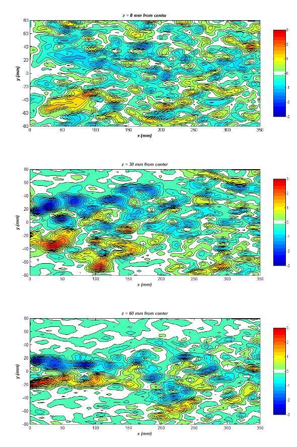
7 Fig. 4 Co-ordinate system used to present the intersecting cylinder results, the origin is defined at the intersection of the two central cylinders at the middle of the grid Shown in Fig. 5 are comparisons of one instance of the U velocity field normalized on the towing speed of 0.1 m/s (Re=3200), at the different z-positions away from the center of the grid. Towards the center, i.e. the intersection of two cylinders, you see the large velocity deficit, and proceeding away from the intersection, the wake of the horizontal cylinder becomes more clearly defined. At z=30mm and 60mm away from the center of the grid, the features visible in the flow field are a result of the wake from the vertical cylinder, whereas at z=90mm from the center, the influence of the vertical wake is not seen until further downstream from the grid, and the horizontal wake is more clearly defined at z=90mm. Identifying the vertical wake is easier if we take a look at the out of plane component of the velocity field, the W velocity. (a) 0 mm from intersection center (b) 30 mm from intersection center (c) 60 mm from intersection center (d) 90 mm from intersection center Fig. 5 Normalized U velocity contours behind the grid of intersecting cylinders at different z-planes for Re=3200. The results shown are representative of 1 of 200 velocity maps taken with the PIV system Shown in Fig. 6, are plots of the W velocity component of the flow at one instance during the measurement. Positive contours (red based colors) indicate the flow is coming out of the plane, and negative (blue based colors) indicate the flow is going into the plane. Behind the center of the grid at z=0mm, there are many areas of the flow moving perpendicular to the measurement plane. These areas decrease as you move away from the center, showing up further downstream of the grid. The Reynolds number effect is difficult to see, but what is indicated is that the vertical wake at Re=3200 spreads quicker than that at Re=6400, as visible in the W contours at - 7 -


8 approximately x=200mm for z=30mm and 60mm, but the effect is reduced downstream at z=90mm for Re=3200 when compared to Re=6400. (a) Re = 3200 (b) Re = 6400 Fig. 6 W-velocity contours behind the grid of intersecting cylinders for the two Reynolds numbers tested at different z planes. While not clearly visible in the figures, the z-planes from top to bottom are z = 0mm, 30mm, 60mm and 90mm Shown in Fig. 7, are the velocity vectors obtained during the measurements. These vectors do show regions of circulating flow indicative of vortices, and also show the influence of the vertical wakes on the downstream development of the horizontal wakes behind the cylinders, with the increased spreading of the wake region at planes closer to the vertical cylinders. From the velocity data, the out of plane component of the vorticity vector can be computed and this is presented in Fig. 8. The two flows are remarkably similar is structure, with the difference being the magnitude of the vorticity being larger for the higher Reynolds number case


 z = 30mm, 60mm - 9 -")
9 (a) Re = 3200 (b) Re = 6400 Fig. 7 Velocity vectors behind the grid of intersecting cylinders for the two Reynolds numbers tested at (from top to bottom) z = 0mm, 30mm, and 60mm (a) Re = 3200 (b) Re = 6400 Fig. 8 Computed z-component of the vorticity vectors behind the grid of intersecting cylinders for the two Reynolds numbers tested at (from top to bottom) z = 30mm, 60mm - 9 -
10 3.2 Tapered Cylinder Studies The results presented here are taken from experiments with the A1, B1 and S cylinder models at Reynolds numbers between Re m = and The co-ordinate system used for the tapered cylinder studies is slightly different from that used in the intersecting cylinder studies, and is shown in Fig. 9 below. Fig. 9 Co-ordinate system used to present the tapered cylinder results The results obtained from tapered models show the characteristic features for this kind of flow, i.e. oblique vortex shedding, vortex dislocations and cellular shedding behavior. It becomes obvious in the distribution of the local Strouhal number, which is defined as St local = f s d local /U where f s is the local shedding frequency, dlocal is the local diameter, and U is the incoming flow velocity, along the cylinder span shown in Fig. 10: Within shedding cells, St local changes linearly, while cell boundaries appear as abrupt jumps. Correspondingly, the straight cylinder shows a flat St local distribution. Fig. 10 Plot of the local Strouhal number distribution along the span of the cylinders Fig. 11a shows the evolving vortices through the cross-flow velocity component sampled along a line parallel to the cylinder axis located 92 mm downstream of cylinder model A1. Repetitive vortex splits are visible which form multiple cells with constant shedding frequencies inside at z/l = 0.6, and t= 2s and again at t=15s. Additionally, a remarkable change in the shedding behavior is recorded: The first half of the record (t<17s) reveals two splits (three cells along the span), while the second half (18<t<30s) shows only one split, located in the middle (two cells)

 Re m = 18.")
11 However, Hsiao et al. (1998) found three shedding cells for this Reynolds number range on cylinders with slightly smaller aspect ratios (10:1). For comparison, Fig. 11b displays the flow 46mm behind the straight model: Slight obliqueness and spanwise non-uniformities are visible while no vortex dislocations take place. The results obtained so far show the advantage of PIV compared to hot-wire anemometry and encourage further investigation. The focus lies on long time series to reveal possible periodicities in shedding schemes and on high-resolved analysis of single vortex split events. (a) Re m = , tapered cylinder model A1 (b) Re m = 2.300, straight cylinder model S Fig. 11 Comparison of the time evolution of the normalized cross flow velocity component v/u between a tapered and straight cylinder. 4. Conclusions Particle Image Velocimetry (PIV) measurements have been made in the MCLab towing tank facility at the Department of Marine Technology at NTNU, in Trondheim, Norway. A customized PIV solution manufactured from Dantec Dynamics that is capable of being submerged underwater was successfully utilized to perform measurements on two different types of turbulent flow fields; behind a grid of intersecting cylinders, and behind a tapered cylinder. The results for the intersecting cylinder cases show a highly turbulent flow characterized by the interaction of the wakes from both vertical and horizontal cylinders. The results from the tapered cylinder study showed that the PIV system was able to capture the vortex shedding dislocations that are typically found in these types of flows due to the spanwise variation of the diameter of the cylinder. The study also highlighted the feasibility of utilizing PIV as a measurement technique in towing tanks. Consequently, the results from the PIV tests will be incorporated into concurrent numerically calculated results of these two test cases ongoing at the Department of Marine Technology at NTNU. This joint approach of numerical and experimental studies highlights the benefit of applying the PIV technique in the ongoing study of marine hydrodynamics at MARINTEK and NTNU. However, the studies also showed that performing PIV measurements in towing tanks is complicated, and further steps have to be undertaken to improve the performance, accuracy, and efficiency of the technique in these facilities
12 5. Acknowledgements The authors would like to thank The Norwegian Research Council and SINTEF Fisheries for their financial support. 6. References Osaka H, Yamada H, Nakamura I, Kumata Y, Kageyama Y (1983) The Structure of a Turbulent Wake behind a Cruciform Circular Cylinder, 1 st Report, The mean velocity field. Bulletin of the JSME 26: Osaka H, Nakamura I, Yamada H, Kumata Y, Kageyama Y (1983) The Structure of a Turbulent Wake behind a Cruciform Circular Cylinder, 2 nd Report The streamwise development of turbulent flow field. Bulletin of the JSME 26: Zdrakovich M M (1983) Interference between two circular cylinders forming a cross. Journal of Fluid Mechanics 128: Zdrakovich M M (1985) Flow around two intersecting cylinders. Journal of Fluids Engineering 107: Fox T A, Toy N (1990) Wind effects on structural intersections. Journal of Wind Engineering and Industrial Aerodynamics 34:27-44 Fox T A (1991) Wake characteristics of two circular cylinders arranged perpendicular to each other. Journal of Fluids Engineering 113:45-50 Fox T A (1992) Interference in the wake of two square section cylinders arranged perpendicular to each other. Journal of Wind Engineering and Industrial Aerodynamics 40: Piccirillo P S, Van Atta C W (1993) Experimental study of vortex shedding behind linearly tapered cylinders at low Reynolds-numbers. Journal of Fluid Mechanics 246: Hsiao F B, Chiang C H (1998) Experimental study of cellular shedding vortices behind a tapered circular cylinder. Experimental Thermal and Fluid Science 17(3): Shirakashi M, Bae H M, Sano M, Takahashi T (1994) Characteristics of Periodic Vortex Shedding from two cylinders in Cruciform arrangement. Journal of Fluids and Structures 8: Raffel M, Willert C, Kompenhans J (1998) Particle Image Velocimetry, a practical guide corrected 3rd printing. Springer Fredriksson D W, Robinson Swift M, Eroshkin O, Tsukrov I, Irish J D, Celikkol B (2005) Moored fish cage dynamics in waves and currents. IEEE Journal of Ocean Engineering 30(1):28-36 Narasimhamurthy V D, Schwertfirm F, Andersson H I, Pettersen, B (2006) Simulation of unsteady flow past tapered circular cylinders using an immersed boundary method. ECCOMAS CFD
 et al. [25], Noack et al. [26] for circular cylinder flows, Van Oudheusden [27] for square cylinder and Durgesh [28] for a flat plate model. The first two modes appear as phase-shifted versions of each
THREE DIMENSIONAL STRUCTURES OF FLOW BEHIND A
 The Seventh Asia-Pacific Conference on Wind Engineering, November 8-12, 29, Taipei, Taiwan THREE DIMENSIONAL STRUCTURES OF FLOW BEHIND A SQUARE PRISM Hiromasa Kawai 1, Yasuo Okuda 2 and Masamiki Ohashi
Wind tunnel effects on wingtip vortices
 48th AIAA Aerospace Sciences Meeting Including the New Horizons Forum and Aerospace Exposition 4-7 January 2010, Orlando, Florida AIAA 2010-325 Wind tunnel effects on wingtip vortices Xin Huang 1, Hirofumi
Keywords: dynamic stall, free stream turbulence, pitching airfoil
 Applied Mechanics and Materials Vol. 225 (2012) pp 103-108 Online available since 2012/Nov/29 at www.scientific.net (2012) Trans Tech Publications, Switzerland doi:10.4028/www.scientific.net/amm.225.103
Influence of rounding corners on unsteady flow and heat transfer around a square cylinder
 Influence of rounding corners on unsteady flow and heat transfer around a square cylinder S. K. Singh Deptt. of Mech. Engg., M. B. M. Engg. College / J. N. V. University, Jodhpur, Rajasthan, India Abstract
EFFECT OF CORNER CUTOFFS ON FLOW CHARACTERISTICS AROUND A SQUARE CYLINDER
 EFFECT OF CORNER CUTOFFS ON FLOW CHARACTERISTICS AROUND A SQUARE CYLINDER Yoichi Yamagishi 1, Shigeo Kimura 1, Makoto Oki 2 and Chisa Hatayama 3 ABSTRACT It is known that for a square cylinder subjected
Quantification of the Effects of Turbulence in Wind on the Flutter Stability of Suspension Bridges
 Quantification of the Effects of Turbulence in Wind on the Flutter Stability of Suspension Bridges T. Abbas 1 and G. Morgenthal 2 1 PhD candidate, Graduate College 1462, Department of Civil Engineering,
Development of Technology to Estimate the Flow Field around Ship Hull Considering Wave Making and Propeller Rotating Effects
 Development of Technology to Estimate the Flow Field around Ship Hull Considering Wave Making and Propeller Rotating Effects 53 MAKOTO KAWABUCHI *1 MASAYA KUBOTA *1 SATORU ISHIKAWA *2 As can be seen from
L'evoluzione delle tecniche sperimentali nell'idrodinamica navale Particle Image Velocimetry, potenzialità, criticità ed applicazioni
 L'evoluzione delle tecniche sperimentali nell'idrodinamica navale Particle Image Velocimetry, potenzialità, criticità ed applicazioni Massimo Falchi, Mario Felli, Giovanni Aloisio, Silvano Grizzi, Fabio
Measurement and simulation of the flow field around a triangular lattice meteorological mast
 Measurement and simulation of the flow field around a triangular lattice meteorological mast Matthew Stickland 1, Thomas Scanlon 1, Sylvie Fabre 1, Andrew Oldroyd 2 and Detlef Kindler 3 1. Department of
Numerical and Experimental Investigation of the Possibility of Forming the Wake Flow of Large Ships by Using the Vortex Generators
 Second International Symposium on Marine Propulsors smp 11, Hamburg, Germany, June 2011 Numerical and Experimental Investigation of the Possibility of Forming the Wake Flow of Large Ships by Using the
THE BRIDGE COLLAPSED IN NOVEMBER 1940 AFTER 4 MONTHS OF ITS OPENING TO TRAFFIC!
 OUTLINE TACOMA NARROWS BRIDGE FLOW REGIME PAST A CYLINDER VORTEX SHEDDING MODES OF VORTEX SHEDDING PARALLEL & OBLIQUE FLOW PAST A SPHERE AND A CUBE SUMMARY TACOMA NARROWS BRIDGE, USA THE BRIDGE COLLAPSED
AN EXPERIMENTAL INVESTIGATION OF SPILLING BREAKERS
 AN EXPERIMENTAL INVESTIGATION OF SPILLING BREAKERS Prof. James H. Duncan Department of Mechanical Engineering University of Maryland College Park, Maryland 20742-3035 phone: (301) 405-5260, fax: (301)
VORTEX SHEDDING AND VORTEX FORMATION FROM A PAIR OF IN-LINE FORCED OSCILLATING TANDEM ARRANGED CIRCULAR CYINDERS IN A UNIFORM FLOW
 5 th International Symposium on Flow Visualization June 5-8,, Minsk, Belarus VORTEX SHEDDING AND VORTEX FORMATION FROM A PAIR OF IN-LINE FORCED OSCILLATING TANDEM ARRANGED CIRCULAR CYINDERS IN A UNIFORM
The Effect of Gurney Flap Height on Vortex Shedding Modes Behind Symmetric Airfoils
 The Effect of Gurney Flap Height on Vortex Shedding Modes Behind Symmetric Airfoils Daniel R. Troolin 1, Ellen K. Longmire 2, Wing T. Lai 3 1: TSI Incorporated, St. Paul, USA, dan.troolin@tsi.com 2: University
EXPERIMENTAL STUDY OF WIND PRESSURES ON IRREGULAR- PLAN SHAPE BUILDINGS
 BBAA VI International Colloquium on: Bluff Bodies Aerodynamics & Applications Milano, Italy, July, 2-24 8 EXPERIMENTAL STUDY OF WIND PRESSURES ON IRREGULAR- PLAN SHAPE BUILDINGS J. A. Amin and A. K. Ahuja
Pressure coefficient on flat roofs of rectangular buildings
 Pressure coefficient on flat roofs of rectangular buildings T. Lipecki 1 1 Faculty of Civil Engineering and Architecture, Lublin University of Technology, Poland. t.lipecki@pollub.pl Abstract The paper
Aerodynamic Measures for the Vortex-induced Vibration of π-shape Composite Girder in Cable-stayed Bridge
 Aerodynamic Measures for the Vortex-induced Vibration of π-shape Composite Girder in Cable-stayed Bridge *Feng Wang 1), Jialing Song 2), Tuo Wu 3), and Muxiong Wei 4) 1), 2, 3), 4) Highway School, Chang
NUMERICAL INVESTIGATION OF THE FLOW BEHAVIOUR IN A MODERN TRAFFIC TUNNEL IN CASE OF FIRE INCIDENT
 - 277 - NUMERICAL INVESTIGATION OF THE FLOW BEHAVIOUR IN A MODERN TRAFFIC TUNNEL IN CASE OF FIRE INCIDENT Iseler J., Heiser W. EAS GmbH, Karlsruhe, Germany ABSTRACT A numerical study of the flow behaviour
WIND AFFECTED ISOTHERMAL AIRFLOW PATTERNS IN A SCALE MODEL OF A SWINE BARN MEASURED WITH PIV SYSTEM
 ISTP-6, 25, PRAGUE 6 TH INTERNATIONAL SYMPOSIUM ON TRANSPORT PHENOMENA WIND AFFECTED ISOTHERMAL AIRFLOW PATTERNS IN A SCALE MODEL OF A SWINE BARN MEASURED WITH PIV SYSTEM Pavel Bárta Czech Technical University,
PRESSURE DISTRIBUTION OF SMALL WIND TURBINE BLADE WITH WINGLETS ON ROTATING CONDITION USING WIND TUNNEL
 International Journal of Mechanical and Production Engineering Research and Development (IJMPERD ) ISSN 2249-6890 Vol.2, Issue 2 June 2012 1-10 TJPRC Pvt. Ltd., PRESSURE DISTRIBUTION OF SMALL WIND TURBINE
Lab 4: Pressure Gradients over a Wing
 2009 Lab 4: Pressure Gradients over a Wing Innovative Scientific Solutions Inc. 2766 Indian Ripple Road Dayton, OH 45440 (937)-429-4980 Lab 4: Pressure Gradients over a Wing Introduction: Like the previous
Wind Flow Validation Summary
 IBHS Research Center Validation of Wind Capabilities The Insurance Institute for Business & Home Safety (IBHS) Research Center full-scale test facility provides opportunities to simulate natural wind conditions
Hydrogen Bubble Seeding for Particle Image Velocimetry
 Hydrogen Bubble Seeding for Particle Image Velocimetry Benjamin T. Hillier 1 and Mitchell A. Schram. 2 The University of Melbourne, Melbourne, Victoria, 3010, Australia Dr. Jason P. Monty 3 The University
ANALYSIS OF THE POSITIVE FORCES EXHIBITING ON THE MOORING LINE OF COMPOSITE-TYPE SEA CAGE
 194 He, W., Li, C.: Analysis of the positive forces exhibiting on ANALYSIS OF THE POSITIVE FORCES EXHIBITING ON THE MOORING LINE OF COMPOSITE-TYPE SEA CAGE Wei He 1* Chunliu Li 2 1 Ocean College, Agricultural
WIND-INDUCED LOADS OVER DOUBLE CANTILEVER BRIDGES UNDER CONSTRUCTION
 WIND-INDUCED LOADS OVER DOUBLE CANTILEVER BRIDGES UNDER CONSTRUCTION S. Pindado, J. Meseguer, J. M. Perales, A. Sanz-Andres and A. Martinez Key words: Wind loads, bridge construction, yawing moment. Abstract.
Undertow - Zonation of Flow in Broken Wave Bores
 Nearshore Circulation Undertow and Rip Cells Undertow - Zonation of Flow in Broken Wave Bores In the wave breaking process, the landward transfer of water, associated with bore and surface roller decay
Application of Simulation Technology to Mitsubishi Air Lubrication System
 50 Application of Simulation Technology to Mitsubishi Air Lubrication System CHIHARU KAWAKITA *1 SHINSUKE SATO *2 TAKAHIRO OKIMOTO *2 For the development and design of the Mitsubishi Air Lubrication System
Effects of seam and surface texture on tennis balls aerodynamics
 Available online at www.sciencedirect.com Procedia Engineering 34 (2012 ) 140 145 9 th Conference of the International Sports Engineering Association (ISEA) Effects of seam and surface texture on tennis
COMPUTATIONAL FLOW MODEL OF WESTFALL'S LEADING TAB FLOW CONDITIONER AGM-09-R-08 Rev. B. By Kimbal A. Hall, PE
 COMPUTATIONAL FLOW MODEL OF WESTFALL'S LEADING TAB FLOW CONDITIONER AGM-09-R-08 Rev. B By Kimbal A. Hall, PE Submitted to: WESTFALL MANUFACTURING COMPANY September 2009 ALDEN RESEARCH LABORATORY, INC.
The effect of two inclined circular plunging jets on air entrainment in an aeration tank
 Computational Methods in Multiphase Flow III 229 The effect of two inclined circular plunging jets on air entrainment in an aeration tank M. S. Baawain, M. Gamal El-Din & D. W. Smith Department of Civil
THE PERFORMANCE OF PLANING HULLS IN TRANSITION SPEEDS
 THE PERFORMANCE OF PLANING HULLS IN TRANSITION SPEEDS BY DOYOON KIM UNIVERSITY OF SOUTHAMPTON LIST OF CONTENTS AIM & OBJECTIVE HYDRODYNAMIC PHENOMENA OF PLANING HULLS TOWING TANK TEST RESULTS COMPUTATIONAL
Ermenek Dam and HEPP: Spillway Test & 3D Numeric-Hydraulic Analysis of Jet Collision
 Ermenek Dam and HEPP: Spillway Test & 3D Numeric-Hydraulic Analysis of Jet Collision J.Linortner & R.Faber Pöyry Energy GmbH, Turkey-Austria E.Üzücek & T.Dinçergök General Directorate of State Hydraulic
ASME International Mechanical Engineering Congress & Exhibition IMECE 2013 November 15-21, 2013, San Diego, California, USA
 ASME International Mechanical Engineering Congress & Exhibition IMECE 2013 November 15-21, 2013, San Diego, California, USA IMECE2013-62734 AERODYNAMIC CHARACTERISTICS OF HORIZONTAL AXIS WIND TURBINE WITH
Pressure distribution of rotating small wind turbine blades with winglet using wind tunnel
 Journal of Scientific SARAVANAN & Industrial et al: Research PRESSURE DISTRIBUTION OF SMALL WIND TURBINE BLADES WITH WINGLET Vol. 71, June 01, pp. 45-49 45 Pressure distribution of rotating small wind
CFD Simulation and Experimental Validation of a Diaphragm Pressure Wave Generator
 CFD Simulation and Experimental Validation of a Diaphragm Pressure Wave Generator T. Huang 1, A. Caughley 2, R. Young 2 and V. Chamritski 1 1 HTS-110 Ltd Lower Hutt, New Zealand 2 Industrial Research Ltd
A Study on the Effects of Wind on the Drift Loss of a Cooling Tower
 A Study on the Effects of Wind on the Drift Loss of a Cooling Tower Wanchai Asvapoositkul 1* 1 Department of Mechanical Engineering, Faculty of Engineering, King Mongkut s University of Technology Thonburi
EXPERIMENTAL STUDY ON SNOW BEHAVIOR AROUND FENCES INSTALLED ALONG ELEVATED HIGHWAY
 ISTP-16, 25, PRAGUE 16 TH INTERNATIONAL SYMPOSIUM ON TRANSPORT PHENOMENA EXPERIMENTAL STUDY ON SNOW BEHAVIOR AROUND FENCES INSTALLED ALONG ELEVATED HIGHWAY Akinori Nakata*, Haruo Soeda*, Junji Onishi*,
FLUID FORCE ACTING ON A CYLINDRICAL PIER STANDING IN A SCOUR
 BBAA VI International Colloquium on: Bluff Bodies Aerodynamics & Applications Milano, Italy, July, 20-24 2008 FLUID FORCE ACTING ON A CYLINDRICAL PIER STANDING IN A SCOUR Takayuki Tsutsui Department of
MICRO-BUBBLE TRACER PARTICLES FOR PLANAR AND VOLUMETRIC PIV
 MICRO-BUBBLE TRACER PARTICLES FOR PLANAR AND VOLUMETRIC PIV APPLICATION NOTE V3V-FLEX-008 (US) Introduction Seed particle tracers for airflow and wind tunnel applications must fulfill a challenging set
Experimental Investigation Of Flow Past A Rough Surfaced Cylinder
 (AET- 29th March 214) RESEARCH ARTICLE OPEN ACCESS Experimental Investigation Of Flow Past A Rough Surfaced Cylinder Monalisa Mallick 1, A. Kumar 2 1 (Department of Civil Engineering, National Institute
The Characteristics of Rim-Driven Propulsor's Flow Field
 The Characteristics of Rim-Driven Propulsor's Flow Field Chung-Wei Lee Department of Systems and Naval Mechatronic Engineering, National Cheng Kung University 1 University Rd., Tainan 70101, Taiwan 1104tom@yahoo.com.tw
A differerential pressure anemometer
 A differerential pressure anemometer S. Kazadi, J. Lee, T.Lee, A. Bose June 6, 2015 Abstract There are a number of different applications where omnidirectional anemometers are needed rather than directional
485 Annubar Primary Flow Element Installation Effects
 ROSEMOUNT 485 ANNUBAR 485 Annubar Primary Flow Element Installation Effects CONTENTS Mounting hole diameter Alignment error Piping Geometry Induced Flow Disturbances Pipe reducers and expansions Control
SEMI-SPAN TESTING IN WIND TUNNELS
 25 TH INTERNATIONAL CONGRESS OF THE AERONAUTICAL SCIENCES SEMI-SPAN TESTING IN WIND TUNNELS S. Eder, K. Hufnagel, C. Tropea Chair of Fluid Mechanics and Aerodynamics, Darmstadt University of Technology
JOURNAL PUBLICATIONS
 1 JOURNAL PUBLICATIONS 71. Lee, T., Mageed, A., Siddiqui, B. and Ko, L.S., (2016) Impact of ground proximity on aerodynamic properties of an unsteady NACA 0012 airfoil, submitted to Journal of Aerospace
Surface obstacles in pulsatile flow
 th International Symposium on Turbulence and Shear Flow Phenomena (TSFP), Chicago, USA, July, 2017 Surface obstacles in pulsatile flow Ian A. Carr, Michael W. Plesniak Department of Mechanical and Aerospace
New Highly Productive Phased Array Ultrasonic Testing Machine for Aluminium Plates for Aircraft Applications
 19 th World Conference on Non-Destructive Testing 2016 New Highly Productive Phased Array Ultrasonic Testing Machine for Aluminium Plates for Aircraft Applications Christoph HENKEL 1, Markus SPERL 1, Walter
THEORETICAL EVALUATION OF FLOW THROUGH CENTRIFUGAL COMPRESSOR STAGE
 THEORETICAL EVALUATION OF FLOW THROUGH CENTRIFUGAL COMPRESSOR STAGE S.Ramamurthy 1, R.Rajendran 1, R. S. Dileep Kumar 2 1 Scientist, Propulsion Division, National Aerospace Laboratories, Bangalore-560017,ramamurthy_srm@yahoo.com
DP Ice Model Test of Arctic Drillship
 Author s Name Name of the Paper Session DYNAMIC POSITIONING CONFERENCE October 11-12, 211 ICE TESTING SESSION DP Ice Model Test of Arctic Drillship Torbjørn Hals Kongsberg Maritime, Kongsberg, Norway Fredrik
EXPERIMENTAL INVESTIGATION OF WAKE SURVEY OVER A CYLINDER WITH DIFFERENT SURFACE PROFILES
 EXPERIMENTAL INVESTIGATION OF WAKE SURVEY OVER A CYLINDER WITH DIFFERENT SURFACE PROFILES Abdul Ahad Khan 1, Abhishek M. B 2, Tresa Harsha P George 3 1 Under Graduate student, Department of Aeronautical
ZIN Technologies PHi Engineering Support. PHi-RPT CFD Analysis of Large Bubble Mixing. June 26, 2006
 ZIN Technologies PHi Engineering Support PHi-RPT-0002 CFD Analysis of Large Bubble Mixing Proprietary ZIN Technologies, Inc. For nearly five decades, ZIN Technologies has provided integrated products and
A Computational Assessment of Gas Jets in a Bubbly Co-Flow 1
 A Computational Assessment of Gas Jets in a Bubbly Co-Flow 1 Melissa Fronzeo*, 1 Michael Kinzel 1 The Pennsylvania State University, University Park, PA, USA Abstract In this effort, Computational Fluid
ISOLATION OF NON-HYDROSTATIC REGIONS WITHIN A BASIN
 ISOLATION OF NON-HYDROSTATIC REGIONS WITHIN A BASIN Bridget M. Wadzuk 1 (Member, ASCE) and Ben R. Hodges 2 (Member, ASCE) ABSTRACT Modeling of dynamic pressure appears necessary to achieve a more robust
AF100. Subsonic Wind Tunnel AERODYNAMICS. Open-circuit subsonic wind tunnel for a wide range of investigations into aerodynamics
 Open-circuit subsonic wind tunnel for a wide range of investigations into aerodynamics Page 1 of 4 Works with Computer, chair and work table shown for photographic purposes only (not included) Screenshot
Tim Lee s journal publications
 Tim Lee s journal publications 82. Lee, T., and Tremblay-Dionne, V., (2018) Impact of wavelength and amplitude of a wavy ground on a static NACA 0012 airfoil submitted to Journal of Aircraft (paper in
Results and Discussion for Steady Measurements
 Chapter 5 Results and Discussion for Steady Measurements 5.1 Steady Skin-Friction Measurements 5.1.1 Data Acquisition and Reduction A Labview software program was developed for the acquisition of the steady
AERODYNAMIC CHARACTERISTICS OF SPIN PHENOMENON FOR DELTA WING
 ICAS 2002 CONGRESS AERODYNAMIC CHARACTERISTICS OF SPIN PHENOMENON FOR DELTA WING Yoshiaki NAKAMURA (nakamura@nuae.nagoya-u.ac.jp) Takafumi YAMADA (yamada@nuae.nagoya-u.ac.jp) Department of Aerospace Engineering,
Methods The experiments were carried out in the wind tunnel in the Air physics laboratory at the Engineering Centre Bygholm as shown in figure 1.
 1 Standardisation of test method for salt spreader: Air flow experiments Report 2: Visualization of airflow patterns by Jan S. Strøm, Consultant Aarhus University, Engineering Centre Bygholm, Test and
The effect of the number of blades on wind turbine wake - a comparison between 2-and 3-bladed rotors
 Journal of Physics: Conference Series PAPER OPEN ACCESS The effect of the number of blades on wind turbine wake - a comparison between 2-and 3-bladed rotors To cite this article: Franz Mühle et al 2016
Investigation of Suction Process of Scroll Compressors
 Purdue University Purdue e-pubs International Compressor Engineering Conference School of Mechanical Engineering 2006 Investigation of Suction Process of Scroll Compressors Michael M. Cui Trane Jack Sauls
FLOW CONSIDERATIONS IN INDUSTRIAL SILENCER DESIGN
 FLOW CONSIDERATIONS IN INDUSTRIAL SILENCER DESIGN George Feng, Kinetics Noise Control, Inc., 3570 Nashua Drive, Mississauga, Ontario Vadim Akishin, Kinetics Noise Control, Inc., 3570 Nashua Drive, Mississauga,
Gravity wave effects on the calibration uncertainty of hydrometric current meters
 Gravity wave effects on the calibration uncertainty of hydrometric current meters Marc de Huu and Beat Wüthrich Federal Office of Metrology METAS, Switzerland E-mail: marc.dehuu@metas.ch Abstract Hydrometric
Undertow - Zonation of Flow in Broken Wave Bores
 Lecture 22 Nearshore Circulation Undertow - Zonation of Flow in Broken Wave Bores In the wave breaking process, the landward transfer of water, associated with bore and surface roller decay within the
3D Turbulence at the Offshore Wind Farm Egmond aan Zee J.W. Wagenaar P.J. Eecen
 3D Turbulence at the Offshore Wind Farm Egmond aan Zee J.W. Wagenaar P.J. Eecen OWEZ_R_121_3Dturbulence_20101008 ECN-E--10-075 OCTOBER 2010 Abstract NoordzeeWind carries out an extensive measurement and
Citation Journal of Thermal Science, 18(4),
,") NAOSITE: Nagasaki University's Ac Title Author(s) Noise characteristics of centrifuga diffuser (Noise reduction by means leading tip) Murakami, Tengen; Ishida, Masahiro; Citation Journal of Thermal Science,
NAOSITE: Nagasaki University's Ac Title Author(s) Noise characteristics of centrifuga diffuser (Noise reduction by means leading tip) Murakami, Tengen; Ishida, Masahiro; Citation Journal of Thermal Science,
A Research on the Airflow Efficiency Analysis according to the Variation of the Geometry Tolerance of the Sirocco Fan Cut-off for Air Purifier
 A Research on the Airflow Efficiency Analysis according to the Variation of the Geometry Tolerance of the Sirocco Fan Cut-off for Air Purifier Jeon-gi Lee*, Choul-jun Choi*, Nam-su Kwak*, Su-sang Park*
Asymmetric vortex shedding flow past an inclined flat plate at high incidence
 Title Asymmetric vortex shedding flow past an inclined flat plate at high incidence Author(s) Lam, KM; Leung, MYH Citation European Journal Of Mechanics, B/Fluids, 5, v. 4 n., p. - 48 Issued Date 5 URL
Introduction to AAE520 Forebody/LDV Lab
 Introduction to AAE520 Forebody/LDV Lab Learn to use a water tunnel Learn about the laser doppler velocimeter (LDV), use it for some measurements Learn about flow visualization Learn about subsonic forebodies
Numerical Simulation And Aerodynamic Performance Comparison Between Seagull Aerofoil and NACA 4412 Aerofoil under Low-Reynolds 1
 Advances in Natural Science Vol. 3, No. 2, 2010, pp. 244-20 www.cscanada.net ISSN 171-7862 [PRINT] ISSN 171-7870 [ONLINE] www.cscanada.org *The 3rd International Conference of Bionic Engineering* Numerical
CFD AND EXPERIMENTAL STUDY OF AERODYNAMIC DEGRADATION OF ICED AIRFOILS
 Colloquium FLUID DYNAMICS 2008 Institute of Thermomechanics AS CR, v.v.i., Prague, October 22-24, 2008 p.1 CFD AND EXPERIMENTAL STUDY OF AERODYNAMIC DEGRADATION OF ICED AIRFOILS Vladimír Horák 1, Dalibor
OPTIMIZATION OF INERT GAS FLOW INSIDE LASER POWDER BED FUSION CHAMBER WITH COMPUTATIONAL FLUID DYNAMICS. Abstract. Introduction
 Solid Freeform Fabrication 2018: Proceedings of the 29th Annual International Solid Freeform Fabrication Symposium An Additive Manufacturing Conference OPTIMIZATION OF INERT GAS FLOW INSIDE LASER POWDER
Numerical Investigation of Flow Around Two Cylinders using Large-Eddy Simulation
 Numerical Investigation of Flow Around Two Cylinders using Large-Eddy Simulation Baraal Qays Mahdi M. Sc. Student, Mechanical Engineering, Department of Mechanical Engineering. Universiti Kebangsaan Malaysia,
EXPERIMENTAL ANALYSIS OF THE CONFLUENT BOUNDARY LAYER BETWEEN A FLAP AND A MAIN ELEMENT WITH SAW-TOOTHED TRAILING EDGE
 24 TH INTERNATIONAL CONGRESS OF THE AERONAUTICAL SCIENCES EXPERIMENTAL ANALYSIS OF THE CONFLUENT BOUNDARY LAYER BETWEEN A FLAP AND A MAIN ELEMENT WITH SAW-TOOTHED TRAILING EDGE Lemes, Rodrigo Cristian,
Effects of separation distance on the vortical behaviour of jetimpingement
 Effects of separation distance on the vortical behaviour of jetimpingement upon convex cylinders Long Jiao 1,* and New Tze How 1 1: School of Mechanical and Aerospace Engineering, Nanyang Technological
Study on the shape parameters of bulbous bow of. tuna longline fishing vessel
 International Conference on Energy and Environmental Protection (ICEEP 2016) Study on the shape parameters of bulbous bow of tuna longline fishing vessel Chao LI a, Yongsheng WANG b, Jihua Chen c Fishery
Development of TEU Type Mega Container Carrier
 Development of 8 700 TEU Type Mega Container Carrier SAKAGUCHI Katsunori : P. E. Jp, Manager, Ship & Offshore Basic Design Department, IHI Marine United Inc. TOYODA Masanobu : P. E, Jp, Ship & Offshore
Introduction to AAE520 Forebody/LDV Lab
 Introduction to AAE520 Forebody/LDV Lab Learn to use a water tunnel Learn about the laser doppler velocimeter (LDV), use it for some measurements Learn about flow visualization Learn about subsonic forebodies
TP Validating a dynamic grid model with tracer gas injection and analysis
 International Gas Research Conference 2014 TP3-12 433 Validating a dynamic grid model with tracer gas injection and analysis S.C. Brussel, R. Warmerdam, J. Weda, E. Hardi,T. van Onna, N. Ligterink, H.
Validation of Measurements from a ZephIR Lidar
 Validation of Measurements from a ZephIR Lidar Peter Argyle, Simon Watson CREST, Loughborough University, Loughborough, United Kingdom p.argyle@lboro.ac.uk INTRODUCTION Wind farm construction projects
Ball impact dynamics of knuckling shot in soccer
 Available online at www.sciencedirect.com Procedia Engineering 34 (2012 ) 200 205 9 th Conference of the International Sports Engineering Association (ISEA) Ball impact dynamics of knuckling shot in soccer
Computational Analysis of Oil Spill in Shallow Water due to Wave and Tidal Motion Madhu Agrawal Durai Dakshinamoorthy
 Computational Analysis of Oil Spill in Shallow Water due to Wave and Tidal Motion Madhu Agrawal Durai Dakshinamoorthy 1 OUTLINE Overview of Oil Spill & its Impact Technical Challenges for Modeling Review
AIRFLOW GENERATION IN A TUNNEL USING A SACCARDO VENTILATION SYSTEM AGAINST THE BUOYANCY EFFECT PRODUCED BY A FIRE
 - 247 - AIRFLOW GENERATION IN A TUNNEL USING A SACCARDO VENTILATION SYSTEM AGAINST THE BUOYANCY EFFECT PRODUCED BY A FIRE J D Castro a, C W Pope a and R D Matthews b a Mott MacDonald Ltd, St Anne House,
Subsonic Wind Tunnel 300 mm
 aerodynamics AF1300 An open circuit suction subsonic wind tunnel with a working section of 300 mm by 300 mm and 600 mm long Screenshot of the optional VDAS software Saves time and money compared to full-scale
LABORATORY EXPERIMENTS ON WAVE OVERTOPPING OVER SMOOTH AND STEPPED GENTLE SLOPE SEAWALLS
 Asian and Pacific Coasts 23 LABORATORY EXPERIMENTS ON WAVE OVERTOPPING OVER SMOOTH AND STEPPED GENTLE SLOPE SEAWALLS Takayuki Suzuki 1, Masashi Tanaka 2 and Akio Okayasu 3 Wave overtopping on gentle slope
Experimental Determination of Temperature and Pressure Profile of Oil Film of Elliptical Journal Bearing
 International Journal of Advanced Mechanical Engineering. ISSN 2250-3234 Volume 4, Number 5 (2014), pp. 469-474 Research India Publications http://www.ripublication.com Experimental Determination of Temperature
The effect of back spin on a table tennis ball moving in a viscous fluid.
 How can planes fly? The phenomenon of lift can be produced in an ideal (non-viscous) fluid by the addition of a free vortex (circulation) around a cylinder in a rectilinear flow stream. This is known as
WindProspector TM Lockheed Martin Corporation
 WindProspector TM www.lockheedmartin.com/windprospector 2013 Lockheed Martin Corporation WindProspector Unparalleled Wind Resource Assessment Industry Challenge Wind resource assessment meteorologists
Flow in a shock tube
 Flow in a shock tube April 30, 05 Summary In the lab the shock Mach number as well as the Mach number downstream the moving shock are determined for different pressure ratios between the high and low pressure
Effect of Flapping Frequency and Leading Edge Profile on Airfoil Leading Edge Vortical Structures
 Effect of Flapping Frequency and Leading Edge Profile on Airfoil Leading Edge Vortical Structures Wesley N. Fassmann Brigham Young University Scott L. Thomson Brigham Young University Abstract By varying
Modelling of Extreme Waves Related to Stability Research
 Modelling of Extreme Waves Related to Stability Research Janou Hennig 1 and Frans van Walree 1 1. Maritime Research Institute Netherlands,(MARIN), Wageningen, the Netherlands Abstract: The paper deals
INTERACTION BETWEEN WIND-DRIVEN AND BUOYANCY-DRIVEN NATURAL VENTILATION Bo Wang, Foster and Partners, London, UK
 INTERACTION BETWEEN WIND-DRIVEN AND BUOYANCY-DRIVEN NATURAL VENTILATION Bo Wang, Foster and Partners, London, UK ABSTRACT Ventilation stacks are becoming increasingly common in the design of naturally
Unsteady Wave-Driven Circulation Cells Relevant to Rip Currents and Coastal Engineering
 Unsteady Wave-Driven Circulation Cells Relevant to Rip Currents and Coastal Engineering Andrew Kennedy Dept of Civil and Coastal Engineering 365 Weil Hall University of Florida Gainesville, FL 32611 phone:
DETRMINATION OF A PLUNGER TYPE WAVE MAKER CHARACTERISTICE IN A TOWING TANK
 The 9 th International Conference on Coasts, Ports and Marine Structures (ICOPMAS 2010) 29 Nov.-1 Dec. 2010 (Tehran) DETRMINATION OF A PLUNGER TYPE WAVE MAKER CHARACTERISTICE IN A TOWING TANK sayed mohammad
Aerodynamic characteristics around the stalling angle of the discus using a PIV
 10TH INTERNATIONAL SYMPOSIUM ON PARTICLE IMAGE VELOCIMETRY PIV13 Delft, The Netherlands, July 1-3, 2013 Aerodynamic characteristics around the stalling angle of the discus using a PIV Kazuya Seo 1 1 Department
Global aerodynamic instability of twin cylinders in cross flow
 Global aerodynamic instability of twin cylinders in cross flow Md. Mahbub Alam 1,* and J.P. Meyer 2 1 Department of Mechanical and Automation Engineering Shenzhen Graduate School, Harbin Institute of Technology
Journal of Engineering Science and Technology Review 9 (5) (2016) Research Article. CFD Simulations of Flow Around Octagonal Shaped Structures
 (2016) Research Article. CFD Simulations of Flow Around Octagonal Shaped Structures") Jestr Journal of Engineering Science and Technology Review 9 (5) (2016) 72-76 Research Article JOURNAL OF Engineering Science and Technology Review www.jestr.org CFD Simulations of Flow Around Octagonal
Jestr Journal of Engineering Science and Technology Review 9 (5) (2016) 72-76 Research Article JOURNAL OF Engineering Science and Technology Review www.jestr.org CFD Simulations of Flow Around Octagonal
Increased streamer depth for dual-sensor acquisition Challenges and solutions Marina Lesnes*, Anthony Day, Martin Widmaier, PGS
 Increased streamer depth for dual-sensor acquisition Challenges and solutions Marina Lesnes*, Anthony Day, Martin Widmaier, PGS Summary The towing depth applicable to dual-sensor streamer acquisition has
Experimental and Theoretical Investigation for the Improvement of the Aerodynamic Characteristic of NACA 0012 airfoil
 International Journal of Mining, Metallurgy & Mechanical Engineering (IJMMME) Volume 2, Issue 1 (214) ISSN 232 46 (Online) Experimental and Theoretical Investigation for the Improvement of the Aerodynamic
Design process to evaluate potential of wind noise at façade elements
 Design process to evaluate potential of wind noise at façade elements Dr.Cristina Paduano 1, Dr.Jennifer Keenahan 1, Réamonn Mac Réamoinn 1 1 Arup, 50 Ringsend Road, Dublin 4, Ireland email: cristina.paduano@arup.com,