Process Analytical Instruments
|
|
|
- Brittney Sparks
- 6 years ago
- Views:
Transcription
1 Process Analytical Instruments US Edition Process Automation Catalog AP 01 Edition 2016


")


")

2 Related catalogs Catalogs for Process Automation SIMATIC Add-ons for the SIMATIC PCS 7 Process Control System E86060-K4678-A121-B ST PCS 7 AO Process Automation AP 11 Components for Continuous Emission Monitoring PDF (E86060-K3511-A100-B3-7600) SIMATIC SIMATIC PCS 7 Process Control System Technology components E86060-K4678-A141-A ST PCS 7 T Process Automation FI 01 Field Instruments for Process Automation Industrial Communication SIMATIC NET IK PI PDF (E86060-K6201-A101-C1-7600) E86060-K6710-A101-B Process Automation SIREC D Display Recorder MP 20 News SITOP KT 10.1 Power supply SITOP E86060-K6020-E101-A E86060-K2410-A101-B Process Automation MP 31 SIPART Controllers and Software SIMATIC Ident ID 10 Industrial Identification Systems PDF/e-book (E86060-K6031-A100-B6-7600) E86060-K8310-A101-B Weighing Technology WT 10 Products for Weighing Technology SITRAIN Training for Industry ITC PDF (E86060-K6410-A101-A5-7600) Only available in German E86060-K6850-A101-C5 SIMATIC ST PCS 7 SIMATIC PCS 7 Process Control System System components E86060-K4678-A111-C Industry Mall Information and Ordering Platform in the Internet:

3 Process Analytical Instruments Process Automation Continuous Gas Analyzers, extractive 1 Continuous Gas Analyzers, in-situ 2 Process Gas Chromatographs 3 Catalog AP US Edition Refer to the Industry Mall for current updates of this catalog: and as PDF at the following address: For comfortable, fast and error free product selection you will get support in our PIA Life Cycle Portal: Please contact your local Siemens branch. Analytical Application Sets 4 General information 5 Siemens AG 2016 Appendix 6 The products and systems described in this catalog are manufactured/distributed under application of a certified quality management system in accordance with DIN EN ISO 9001.

4 2 Siemens AG 2016

5 Answers for industry. Integrated technologies, vertical market expertise and services for greater productivity, energy efficiency, and flexibility. Siemens is the world's leading supplier of innovative and environmentally friendly products and solutions for industrial companies. End-to-end automation technology and industrial software, solid market expertise, and technology-based services are the levers we use to increase our customers productivity, efficiency and flexibility. We consistently rely on integrated technologies and, thanks to our bundled portfolio, we can respond more quickly and flexibly to our customers' wishes. With our globally unmatched range of automation technology, industrial control and drive technology as well as industrial software, we equip companies with exactly what they need over their entire value chain from product design and development to production, sales and service. Our industrial customers benefit from our comprehensive portfolio, which is tailored to their market and their needs. Market launch times can be reduced by up to 50% due to the combination of powerful automation technology and industrial software. At the same time, the costs for energy or waste water for a manufacturing company can be reduced significantly. In this way, we increase our customers competitive strength and make an important contribution to environmental protection with our energy-efficient products and solutions. 3
6 Efficient automation starts with efficient engineering. Totally Integrated Automation: Efficiency driving productivity. Efficient engineering is the first step toward better production that is faster, more flexible, and more intelligent. With all components interacting efficiently, Totally Integrated Automation (TIA) delivers enormous time savings right from the engineering phase. The result is lower costs, faster time-to-market, and greater flexibility. 4

7 A unique complete approach for all industries Totally Integrated Automation Efficient interoperability of all automation components As one of the world's leading automation suppliers, Siemens provides an integrated, comprehensive portfolio for all requirements in process and manufacturing industries. All components are mutually compatible and system-tested. This ensures that they reliably perform their tasks in industrial use and interact efficiently, and that each automation solution can be implemented with little time and effort based on standard products. The integration of many separate individual engineering tasks into a single engineering environment, for example, provides enormous time and cost savings. With its comprehensive technology and industry-specific expertise, Siemens is continuously driving progress in manufacturing industries and Totally Integrated Automation plays a key role. Totally Integrated Automation creates real value added in all automation tasks, especially for: Integrated engineering Consistent, comprehensive engineering throughout the entire product development and production process Industrial data management Access to all important data occurring in productive operation along the entire value chain and across all levels Industrial communication Integrated communication based on international cross-vendor standards that are mutually compatible Industrial security Systematic minimization of the risk of an internal or external attack on plants and networks Safety Integrated Reliable protection of personnel, machinery, and the environment thanks to seamless integration of safety technologies into the standard automation Making things right with Totally Integrated Automation Totally Integrated Automation, industrial automation from Siemens, stands for the efficient interoperability of all automation components. The open system architecture covers the entire production process and is based on end-to-end shared characteristics: consistent data management, global standards, and uniform hardware and software interfaces. Totally Integrated Automation lays the foundation for comprehensive optimization of the production process: Time and cost savings due to efficient engineering Minimized downtime due to integrated diagnostic functions Simplified implementation of automation solutions due to global standards Better performance due to interoperability of systemtested components 5
.")

8 Totally Integrated Power We bring power to the point safely and reliably. Efficient, reliable, safe: These are the demands placed on electrification and especially power distribution. And our answer for all application areas of the energy system is Totally Integrated Power (TIP). It s based on our comprehensive range of products, systems, and solutions for low and medium voltage, rounded out by our support throughout the entire lifecycle from planning with our own software tools to installation, operation, and services. Comprehensive answers for power distribution in complex energy systems from Siemens Smart interfaces allow linking to industrial or building automation, making it possible to fully exploit all the optimization potential of an integrated solution. This is how we provide our customers around the world with answers to their challenges. With highly efficient, reliable, and safe power distribution, we lay the foundation for sustainable infrastructure and cities, buildings, and industrial plants. We bring power to the point wherever and whenever it is needed. More information: 6
9 Totally Integrated Power offers more: Consistency: For simplified plant engineering and commissioning as well as smooth integration into automation solutions for building or production processes One-stop-shop: A reliable partner with a complete portfolio for the entire process and lifecycle from the initial idea to after-sales service Safety: A comprehensive range of protection components for personnel safety and line and fire protection, safety by means of type testing Reliability: A reliable partner who works with customers to develop long-lasting solutions that meet the highest quality standards Efficiency: Bringing power to the point means greater plant availability and maximum energy efficiency in power distribution Flexibility: End-to-end consistency and modular design of Totally Integrated Power for any desired expansions and adaptation to future requirements Advanced technology: Reliable power distribution especially for applications in which supply is critical, continuous refinement of the technology Challenges are our speciality Automation Process/ Industrial automation Operation & Monitoring Load curves Forecast Load management Maintenance Status reporting/ failure management Protocols Power Quality Cost center Building automation PROFINET PROFIBUS... Industrial Ethernet Modbus Electrification Renewables Storage technologies Medium-voltage switchgear and protection technology Transformer Low-voltage switchboard with protection and measuring technology Low-voltage distribution 110 kv Products, systems and solutions Consulting, planning Engineering Order, delivery Installation, commissioning Operation Service, modernization 7


10 Industries In the field of process instrumentation, process analytics and weighing technology, Siemens focuses on a number of key industries such as: Chemical Pharmaceutical Water/wastewater Mining, aggregates, cement Oil and gas/hydrocarbon processing Pulp and paper Food and beverage Marine 8

11 Process Analytics Siemens is a leading provider of process gas analyzers and analysis systems. We provide our global users the best solutions for their applications based on innovative analysis technologies, customized system engineering, sound knowledge of process applications and strong professional support. And with Totally Integrated Automation, Siemens Analytical Products and Solutions is your qualified partner for efficient solutions that seamlessly integrates process gas analyzers into automation systems in the process industry. 9


12 Continuous Gas Analytics From emission monitoring in waste incinerators and power plants, gas analysis in the chemical industry and rotary kiln monitoring in cement plants, the extremely accurate and reliable Siemens gas analyzers are the perfect solution for the job. SITRANS SL Continuous gas analyzer with benchmarksetting in-situ technology for process control even under extreme measuring conditions. 10
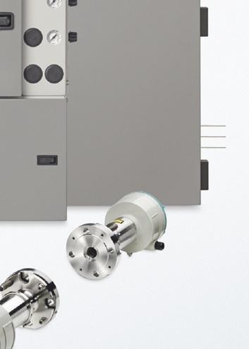
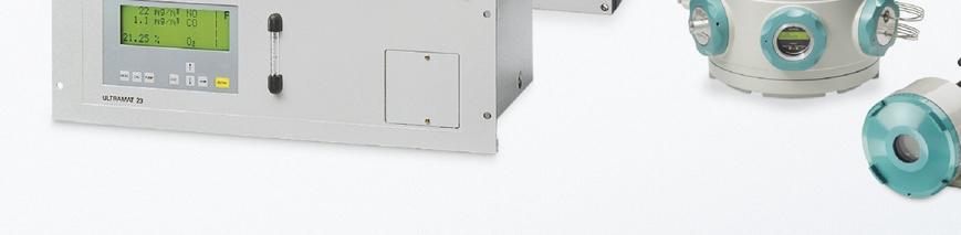
![[1] [2] [3] The technology used in process gas analyzers is determined by the requirements of the specific application.](/docs-images/75/71718389/images/13-0.jpg "The analyzers must be cost-effective, functional, space- and energy-saving, and must provide just the right amount of power to meet all needs.")

 concept and are programmed using SIMATIC PDM software and PROFIBUS DP / PA interfaces.")

13 [1] [2] [3] The technology used in process gas analyzers is determined by the requirements of the specific application. The analyzers must be cost-effective, functional, space- and energy-saving, and must provide just the right amount of power to meet all needs. Siemens Analytical Products and Solutions offers a comprehensive analytical portfolio to meet all user requirements for complete measurement solutions. We combine proven expertise in developing high-performance analytical devices with in-depth application knowledge from many process industry applications. The analyzers operate using a menu structure and comply with the NAMUR recommendations. The analyzers can be easily integrated into the SIMATIC automation Totally Integrated Automation (TIA) concept and are programmed using SIMATIC PDM software and PROFIBUS DP / PA interfaces. For service and maintenance tasks with our extractive process gas analyzers is the SIPROM GA software tool suitable. Integration into the Ethernet permits remote servicing and diagnostics over long distances. PROCESS GAS ANALYSIS EXTRACTIVE ULTRAMAT 23 [1] is an innovative multicomponent analyzer for the measure ment of up to 3 infrared sensitive gases using the NDIR principle as well as measuring oxygen (O 2 ) using an electrochemical or paramagnetic oxygen measuring cell. The ULTRAMAT 23 is also available with a build-in H 2 S- sensor for biogas applications. SERIES 6 The Series 6 gas analyzers are a family of gas analyzers that meet a complete range of measurement requirements: CALOMAT 6 [2] [3] is available in both 19 rack mount and field mount designs and uses the thermal conductivity measurement principle to accurately measure the composition and concentration of process gases. It is primarily designed for the measurement of hydrogen concentrations in inert gas such as blast furnace gases and carbon dioxide mixtures. CALOMAT 62 [2] [3] uses the thermal conductivity detection (TCD) principle and is specially designed for use in applications with corrosive gases such as chlorine. The CALOMAT 62 measures the concentration of gas components such as H 2, Cl 2, HCl or NH 3 in binary or quasi-binary gas mixtures. FIDAMAT 6 [3] measures the total hydrocarbon content in air or even in high-boiling gas mixtures. It is the ideal solution for nearly all measurement requirements, from emission monitoring as well as trace measurements of hydrocarbons in pure gas analysis and total measurement of high hydrocarbon concentrations, even in the presence of corrosive gases. The ULTRAMAT 23 is suitable for a wide range of standard applications, such as emission monitoring, furnace optimization, room air monitoring and other applications. Calibration using ambient air eliminates the need for expensive calibration gases. 11
![Continuous Gas Analytics [1] [2] [3] OXYMAT 6 [1] [2] is an oxygen analyzer available in either a 19 rack mount or in a robust field housing for installation in harsh environments.](/docs-images/75/71718389/images/14-1.jpg "The OXYMAT 6 can be used for emission measurements in production process control and quality assurance. Due to its ultrafast response, the OXYMAT 6 is perfect for safety-related measurements.")
![OXYMAT 61 [1] is a low-cost oxygen analyzer for standard applications. It can use ambient air as a reference gas that is supplied to the analyzer section by the internal pump.](/docs-images/75/71718389/images/14-3.jpg "OXYMAT 64 [1] is a gas analyzer for the measurement of extremely low oxygen concentrations.")
14 Continuous Gas Analytics [1] [2] [3] OXYMAT 6 [1] [2] is an oxygen analyzer available in either a 19 rack mount or in a robust field housing for installation in harsh environments. The OXYMAT 6 can be used for emission measurements in production process control and quality assurance. Due to its ultrafast response, the OXYMAT 6 is perfect for safety-related measurements. OXYMAT 61 [1] is a low-cost oxygen analyzer for standard applications. It can use ambient air as a reference gas that is supplied to the analyzer section by the internal pump. OXYMAT 64 [1] is a gas analyzer for the measurement of extremely low oxygen concentrations. Air separation plants and production of technical gases are just a few examples where the OXYMAT 64 reliably detects traces of oxygen. Ex-proof designs [2] are possible with an additional purge monitoring unit for the CALOMAT 6, OXYMAT 6 and ULTRAMAT 6 gas analyzers using the field housing for installation in hazardous areas. Measurements can include both nonflammable and flammable gases. SIPROCESS UV600 [3] is an extractive UV gas analyzer for simultaneous measurement of up to 3 components. It is especially suitable to measuring very low concentrations of NO, NO 2, SO 2 or H 2 S. Simultaneous measurement of NO and NO 2 offers total NO x determination without the need for additional devices like NO 2 converters or CLD analyzers. ULTRAMAT 6 [1] [2] is an analyzer available in both 19 rack mount or field housing. Measurement of up to four infrared active components is possible in a single unit. It can be used in all applications from emission monitoring to process control, even in the presence of highly corrosive gases. ULTRAMAT/OXYMAT 6 [1] can be combined in a 19 rack to form multi-component devices with ULTRAMAT 6 and OXYMAT 6 benches. This provides, in the smallest possible footprint, an infrared channel for the measurement of up to two IR components and a channel for oxygen measurement. 12
![[4] [5] PROCESS GAS ANALYSIS IN-SITU (TDLS) LDS 6 [4] brings together the compact and service-friendly design, simple operation and network capability of the Series 6 analyzers with the well-known](/docs-images/75/71718389/images/15-0.jpg "exceptional performance of in-situ gas analysis by using tunable diode laser spectroscopy (TDLS) and fiber optics.")


15 [4] [5] PROCESS GAS ANALYSIS IN-SITU (TDLS) LDS 6 [4] brings together the compact and service-friendly design, simple operation and network capability of the Series 6 analyzers with the well-known exceptional performance of in-situ gas analysis by using tunable diode laser spectroscopy (TDLS) and fiber optics. It can measure gases even under extreme conditions such as C (2 192 F) or very high dust concentration with precise and reliable results. The LDS 6, for example, measures in-situ concentrations of O 2, NH 3, HCl, HF H 2 O, CO or CO 2 in flue gas before and after gas cleaning. Applications in the chemical and petrochemical industries, for steel and metal production, as well as in cement or paper plants are ideally suited for the LDS 6. SITRANS SL [5] combines the benefits of proven referencing technology with a direct operating mode as close as possible to the process. An integrated reference cell, filled with a non-interfering gas allows laser locking completely independent of process gas concentrations leading to extremely stable operation, negligible drift values and extended on-line availability. This patented feature guarantees reliable measurement of gas concentration even at values close to zero. SITRANS SL is housed with a compact design, including a local user interface (LUI), making it the perfect solution for single point measurement applications in rough environments. SITRANS SL is used for process control in the chemical industry, even in hazardous areas due to its Ex d design. It is also suitable for installation in SIL applications. Analyzer System Manager (ASM) is a PC-based HMI system for monitoring, testing and administration of gas analyzers in subsystems or in an entire plant. Key performance information of the analyzers is collected over a variety of common communication interfaces and is saved in a central database. By means of the PC s user-friendly operator interface, it is possible to access measured-value trends, device statuses and statistical evaluations, among others, or to start test routines for validation of the results. A comprehensive reporting module is available to document the evaluations. The ASM is ideal for all analytical systems where high reliability of the measured values and documentation of the analyzer performances is required. Using the communications network, remote analyzers can also be monitored from a central workstation. The ASM can be applied in new plants or also in existing plants to optimize the analyzer landscape. 13


16 Process Gas Chromatography Siemens application experience and innovative technology in the field of process gas chromatography enables us provide the perfect measurement solutions for our customers. With our analyzers, we solve a wide range of measurement challenges in almost any industry combining exceptional performance with the lowest cost-of-ownership. SITRANS CV Ultra compact gas chromatograph for reliable, exact and fast analysis of natural gas and biogas. 14
![[1] [2] MicroSAM [1] is a small flexible explosion-proof on-line process gas chromatograph made by Siemens.](/docs-images/75/71718389/images/17-0.jpg "State-of-the-art silicon-based micromechanical components allow miniaturization as well as increased performance at the same time.")


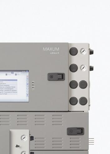
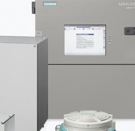
17 [1] [2] MicroSAM [1] is a small flexible explosion-proof on-line process gas chromatograph made by Siemens. State-of-the-art silicon-based micromechanical components allow miniaturization as well as increased performance at the same time. MicroSAM s ease of use and rugged small design that makes it ideal for mounting right at the sampling point. Its features include: Leading edge technology drastically reduces analysis times, providing better information about the process Valveless live sample injection and column switching dramatically reduces hardware complexity and maintenance Multiple detection for verification of the results Synchronization of multiple analyzers that are connected in parallel for several sample streams, results in more information per time unit, a high degree of reliability should one of the systems fail, and easy implementation of redundant systems Cost-effective and compact design saves installation, maintenance, and service costs SITRANS CV [1] is a gas chromatograph for reliable, exact and fast analysis of natural gas and biogas. The rugged and compact design makes the SITRANS CV suitable for extreme locations, e. g. off-shore platforms or direct mounting on a pipeline. Operation of SITRANS CV using CV Control software is simple and fast. The Software CV Control has been specially developed for the requirements of the natural gas market, e. g. custody transfer. MAXUM edition II [2] is ideal for use in rough industrial environments and performs a wide range of duties in the chemical and, petrochemical and refineries. A wide selection of columns and detectors permits highly selective and sensitive analysis of multiple process components. Benefits of MAXUM edition II include: A variety of oven options including temperature programmable and energy saving single or dual airless ovens Wide selection of valve types for sample injection and column switching including live valveless switching for almost no dead volume Parallel chromatography simplifies even the most complex analysis systems as well as dramatically reducing measurement cycle times New guiding technology with modular design for fast maintenance and higher availability for measurement and for customers process optimisation Open network with TCP/IP and Ethernet for communication with PC workstations, other chromatographs or a DCS 15


 up to fully air-conditioned analyzer shelters Support during the")
18 Analytical Application Sets and Solutions Our customers requirements drive the solution. We offer comprehensive designs covering the sampling point and sample preparation up to complete analyzer cabinets whether used for portable applications or for installation in a larger analyzer shelter. Signal processing and communications to the control room and process control system is also part of the total system solution. Our solutions for your application needs are based on decades of global experience in process automation and engineering as well as specialized knowledge in key industries and industrial sectors. This guarantees you get Siemens quality from a single source with performance across the entire system. Our portfolio of products and services include: Customized services and solutions from front-end engineering and design (FEED) up to fully air-conditioned analyzer shelters Support during the approval phase Preliminary and detailed planning with state-of-the-art tools and complete documentation System assembly and testing available in Siemens facilities in the USA, Germany and Singapore Experience with all relevant national and international standards Remote maintenance, on-site servicing, spare parts supplies and customized training Analytical Application Sets are standardized system solutions for a number of specific applications. Siemens offers ready-to-use developed solution sets for various industries like e. g. energy and natural gas. Standardized packages include the Set CEM 1 and Set CEM CERT for the emission monitoring market. Specifically designed for the natural gas market is the Set CV (calorific value). The Set CV includes a variety of modules, which can be individually combined. For the monitoring of hydrogen-cooled turbo generators the Set GGA is the state-of-the-art solution. The Set BGA offers a modular a standardized solution for the biogas market. We would be pleased to demonstrate our expertise as our references speak for themselves! Field commissioning and start-up by specialists all over the world 16

19 Continuous Gas Analyzers, extractive Siemens AG /2 Introduction 1/5 ULTRAMAT 23 1/5 General information 1/18 19" rack unit and portable version 1/40 Documentation, Suggestions for spare parts 1/41 ULTRAMAT 6 1/41 General information 1/48 19" rack unit 1/62 Field device 1/73 Documentation 1/74 Suggestions for spare parts 1/75 ULTRAMAT/OXYMAT 6 1/75 General information 1/84 19" rack unit 1/96 Documentation 1/97 Suggestions for spare parts 1/98 OXYMAT 6 1/98 General information 1/106 19" rack unit 1/113 Field device 1/120 Documentation 1/121 Suggestions for spare parts 1/122 OXYMAT 61 1/122 General information 1/127 19" rack unit 1/132 Documentation 1/133 Suggestions for spare parts 1/134 OXYMAT 64 1/134 General information 1/141 19" rack unit 1/147 Documentation, Suggestions for spare parts 1/148 CALOMAT 6 1/148 General information 1/153 19" rack unit 1/160 Field device 1/167 Documentation, Suggestions for spare parts 1/168 CALOMAT 62 1/168 General information 1/173 19" rack unit 1/179 Field device 1/186 Documentation, Suggestions for spare parts 1/187 FIDAMAT 6 1/187 General information 1/193 19" rack unit 1/200 Documentation 1/201 Suggestions for spare parts 1/202 SIPROCESS UV600


20 Continuous Gas Analyzers, extractive Introduction 1 Overview Siemens process gas analyzers have been used in the process industry for more than 40 years, and are renowned for their quality, reliability and accuracy. The flexibility provided by the continuous process gas analyzers with respect to housing design, explosion protection, corrosion resistance and communications capability means that optimum solutions can be found for all applications. Nowadays, the communications capability of analyzers is becoming increasingly important. Siemens process gas analyzers are an integral component of Siemens "Totally Integrated Automation" concept which is globally unique. This concept permits design of uniform process communication from the operations management level down to the field level. The simple integration of analyzers into the host control systems is the basis for a uniform automation and analysis solution. Many years of experience in the development and production of analyzers as well as in the planning and installation of analyzer systems distinguishes Siemens as a solution provider - reliable, innovative and with global presence. Process line Sampling Sample gas Sample preparation Analyzer Process feedback/ exhaust Schematic representation of the measuring setup of extractive site installations 1/2
21 Extractive procedures for process gas analysis Extractive process gas analyzers are used for continuous determination of the concentrations of one or more gases in a gas mixture. Determination of the concentration of gases in a process is used to control and monitor process flows, and is therefore decisive for the automation and optimization of processes and ensuring product quality. In addition, process gas analyzers are used to check emissions, thus making an important contribution to environmental protection, as well as for ensuring compliance with statutory directives. With extractive measuring procedures, the sample to be analyzed is extracted from the process line and applied preconditioned to the analyzer via a sample line and a sample preparation system. This system, for example, adjusts the pressure, temperature and flow of the sample, and frees the sample gas of dust and moisture if necessary. This guarantees that the measurement can be carried out under defined conditions. Furthermore, the analyzer is protected from damaging influences. Various measuring procedures with different physical and electrochemical methods are used depending on the type of components to be measured and the measuring point. Continuous Gas Analyzers, extractive Introduction Series6/ ULTRAMAT23 The classic analyzers from Siemens, Series 6 and ULTRAMAT 23, have been proven at our customers all over the globe in many years of use: ULTRAMAT 6 For highly-selective measurement of infrared-active components such as CO, CO 2, NO, SO 2, NH 3, H 2 O, CH 4 and other hydrocarbons. The ULTRAMAT 6 is a high-end analyzer in 19" format or in a sturdy field housing for use in harsh atmospheres. The field of application basically comprises all types of emission measurements up to use in processes. These serve to control production processes and guarantee product quality, even in the presence of highly corrosive gases. ULTRAMAT 23 The ULTRAMAT 23 is an innovative multi-component gas analyzer for measuring up to three infrared-sensitive gases using the NDIR principle. Measurement of oxygen (O 2 ) is also possible through the use of electrochemical oxygen sensors or measuring cells operating according to the paramagnetic principle ("dumbbell"). The use of an additional electrochemical H 2 S measuring cell permits use in biogas applications. ULTRAMAT/OXYMAT 6 For combined measurement of infrared-active components and oxygen in complex applications. OXYMAT 6 For measurement of oxygen concentration according to the paramagnetic principle in complex applications. The OXYMAT 6 measures oxygen according to the paramagnetic alternating pressure principle. This guarantees absolute linearity and allows the use of very small measuring ranges from 0 to 0.5 % (detection limit 50 vpm), ranges up to 0 to 100 %, and even 99.5 to 100 % in one unit. Suitable materials in the gas path even permit the analyzers to be used for measurement of corrosive gas mixtures. The detector unit does not come into contact with the sample gas, and therefore permits use in harsh atmospheres while simultaneously guaranteeing a long service life. OXYMAT 61 For measurement of oxygen concentrations according to the paramagnetic principle in standard applications. Ambient air can be used as the reference gas for OXYMAT 61. This is supplied by a pump integrated in the analyzer enclosure. OXYMAT 64 For measurement of oxygen concentrations in the trace range by means of ZrO 2 sensors. The OXYMAT 64 can be used to measure very small traces of oxygen, down to the smallest measuring range of 0 to 10 vpm. This is particularly interesting in systems for air separation. A catalytically inactive ZrO 2 sensor or a catalytically active ZrO 2 sensor can be selected, depending on the application. CALOMAT 6 For determining the concentration of hydrogen and inert gases in binary mixtures through measurement of thermal conductivity. The CALOMAT 6 features a high dynamic measuring range (e.g. 0 1 % and % H 2, parameterizable) and a short T 90 time. CALOMAT 62 The CALOMAT 62 is a thermal conductivity analyzer that has been specially designed for applications with corrosive gases. It is possible to directly measure the concentration of gas components such as Cl 2, HCl and NH 3, as well as e.g. H 2 and N 2 in a corrosive atmosphere. 1 1/3
22 Continuous Gas Analyzers, extractive Introduction 1 FIDAMAT 6 For measurement of total hydrocarbons according to the flame ionization principle. The FIDAMAT versions feature a highly varied field of application. From monitoring for traces of hydrocarbons in ultrapure gases - made possible by the high resolution and small differences in response factors - up to measurements of total hydrocarbons in the % range. The widely adjustable operating temperature for the sample gas path and detector also allows measurement of highboiling mixtures and of hydrocarbons at water vapor concentrations up to 100 %. SIPROCESS UV600 Gas analyzer based on UV resonance absorption spectrometry for measuring even very low NO, NO 2, SO 2, and H 2 S concentrations. General information Introducing flammable gases Introducing frequently or permanently explosive gas/air mixtures to the gas analyzers mentioned in this chapter is not permitted. The introduction of gases with flammable components at concentrations above the lower explosive limit (LEL) should only be carried out with analyzers fitted with piping. Purging of the housing as well as further measures must be carried out depending on the application. When using SIPROCESS UV600, please contact the technical department. An inert gas must be used for purging (see manual for further information). Cross-sensitivity Exact measurement results with regard to the technical specifications can only be expected if a sample gas is free to the greatest possible extent of gases exhibiting a cross-sensitivity with the measured component. The influences of these interfering components can be reduced using various measures. Please contact our specialists if you have any questions. General installation guide and operating instructions Protected against low temperatures and thermal radiation (see technical specifications) Protected against temperature variations To achieve the best possible measuring quality, the installation location should be free from vibrations Protection of electronics from corrosive environments (use field devices with purging if necessary) Observation of directives for installation in hazardous areas (see manual) Observation of directives for measurement in the presence of toxic gases, provide purging of enclosure and further safety measures if necessary (see manual) The analyzers in the basic version are set to a cross-influence of water vapor with a dew point of 4 C (standard cooler temperature for sample preparation). When calibrating with zero gas and span gas, these must be connected via the sample gas cooler analogous to the sample gases to allow correct adjustment. In special cases (test measurements or long-term adjustments), it is recommendable to connect the calibration gases via a humidifier upstream of the cooler to avoid "drying-out" of the gas cooler and thus changes in the concentration of the water vapor. Correction of cross-interference which may be activated for a gas is canceled for the duration of a calibration procedure (zero point and sensitivity). Calibration/adjustment The Series 6 analyzers (ULTRAMAT 6, OXYMAT 6, CALOMAT 6) should be calibrated with zero and calibration gas at least every 14 days. Standard Zero gas N 2 (5.0) Calibration gas Sample gas with approx % of measuring range in residual N 2 (5.0) Note: With OXYMAT 6/61 the zero gas and the reference gas must be the same. Pre-purging of sample gas path via the sample gas inlet with nitrogen (N 2, quality 5.0), duration: min. 1 min, one further minute in addition for each 10 m of sample gas line. Calibration gases for zero point adjustment (ULTRAMAT 6, OXYMAT 6, CALOMAT 6) Sufficient supply of inert gas via the sample gas inlet (free from measured component and free from gases with a crossinfluence on the measured component), usually N 2, quality 5.0. Gases for calibration of deflection Connection of calibration gas via the sample gas inlet (approx. 60 to 90 % of the measuring range of the measured component with inert gas as the residual gas (e.g. N 2, quality 5.0)). Gases for calibration of the CALOMAT 62 Since every residual gas (including nitrogen) has a specific thermal conductivity, the gases used for calibrating the zero point and full-scale values of the CALOMAT 62 must take this into account. When calibrating e.g. H 2 in HCl, HCl can be used as the zero gas (or an appropriate substitute in accordance with the data sheet enclosed with the device) and H 2 in HCl (or a substitute gas) as the span gas. You can find details on FIDAMAT 6, OXYMAT 64 and ULTRAMAT 23 (AUTOCAL) in the chapters describing the respective device. Explosion protection Refer to the separate manuals, references and standards concerning the topic of explosion protection. 1/4
23 Continuous Gas Analyzers, extractive ULTRAMAT 23 Overview Up to four gas components can be measured simultaneously with the ULTRAMAT 23 gas analyzer: up to three infrared-active gases such as CO, CO 2, NO, SO 2, CH 4, plus O 2 with an electrochemical oxygen sensor. ULTRAMAT 23 basic versions for: 1 infrared gas component with/without oxygen measurement 2 infrared gas components with/without oxygen measurement 3 infrared gas components with/without oxygen measurement With the ULTRAMAT 23 gas analyzer for use in biogas plants, up to four gas components can be measured continuously: two infrared-sensitive gases (CO 2 and CH 4 ), plus O 2 and H 2 S with electrochemical measuring cells. With the ULTRAMAT 23 gas analyzer with paramagnetic oxygen cell, up to four gas components can be measured continuously: three infrared-active gases, plus O 2 ("dumbbell" measuring cell). General information Benefits AUTOCAL with ambient air (dependent on the measured component) Highly cost effective because calibration gases are not required High selectivity thanks to multi-layer detectors, e.g. low cross-sensitivity to water vapor Sample chambers can be cleaned as required on site Cost savings due to reuse after contamination Menu-assisted operation in plaintext Operator control without manual, high level of operator safety Service information and logbook Preventive maintenance; help for service and maintenance personnel, cost savings Coded operator level against unauthorized access Increased safety Open interface architecture (RS 485, RS 232, PROFIBUS, SIPROM GA) Simplified process integration; remote operation and control Special benefits when used in biogas plants Continuous measurement of all four important components, including H 2 S Long service life of the H 2 S sensor even at increased concentrations; no diluting or backflushing necessary Introduction and measurement of flammable gases as occurring in biogas plants (e.g. 70 % CH 4 ), is permissible (TÜV certificate) 1 1/5
24 Continuous Gas Analyzers, extractive ULTRAMAT 23 General information 1 Application Areas of application Optimization of small firing systems Monitoring of exhaust gas concentration from firing systems with all types of fuel (oil, gas and coal) as well as operational measurements with thermal incineration plants Room air monitoring Monitoring of air in fruit stores, greenhouses, fermenting cellars and warehouses Monitoring of process control functions Atmosphere monitoring during heat treatment of steel For use in non-potentially-explosive atmospheres Application areas in biogas plants Monitoring of fermenters for generating biogas (input and pure sides) Monitoring of gas-driven motors (power generation) Monitoring of feeding of biogas into the commercial gas network Application area of paramagnetic oxygen sensor Flue gas analysis Inerting plants Room air monitoring Medical engineering Further applications Environmental protection Chemical plants Cement industry Special versions Separate gas paths The ULTRAMAT 23 with 2 IR components without pump is also available with two separate gas paths. This allows the measurement of two measuring points as used e.g. for the NO x measurement before and after the NO x converter. The ULTRAMAT 23 gas analyzer can be used in emission measuring systems and for process and safety monitoring. Versions conforming to EN and EN According to EN 14181, which is standardized in the EU and required in many European countries, a QAL 1 qualification test, i.e. certification of the complete measuring system including gas paths and conditioning, is required for continuous emission monitoring systems (CEMS). In accordance with EN 15267, this must be performed by an independent accredited authority. In Germany, for example, the test is performed by the German Technical Inspectorate (TÜV) and the test report is submitted to the Federal/State Workgroup for Emission Control (Bund/Länder-Arbeitsgemeinschaft für Immissionsschutz - LAI) for examination/approval. Notification is also issued by the German Federal Environment Agency (Umweltbundesamt - UBA) in the Federal Gazette as well as by the German Technical Inspectorate (TÜV) on For use in EN applications, the devices with the article numbers 7MB235X in the CEM CERT set (7MB1957) have undergone qualification testing according to German standards of EN These German Technical Inspectorate versions of the ULTRAMAT are suitable for measurement of CO, NO, SO 2 and O 2 according to 13th and 27th BlmSchV as well as TA Luft. Smallest measuring ranges tested and approved by the German Technical Inspectorate: - 1 and 2-component analyzer CO: 0 to 200 mg/m 3 NO: 0 to 150 mg/m 3 SO 2 : 0 to 400 mg/m 3-3-component analyzer CO: 0 to 250 mg/m 3 NO: 0 to 400 mg/m 3 SO 2 : 0 to 400 mg/m 3 Also tested as additional measuring ranges in accordance with EN : CO: 0 to mg/m 3 NO: 0 to mg/m 3 SO 2 : 0 to mg/m 3 Determination of the analyzer drift according to EN (QAL 3) can be carried out manually or with a PC using the SIPROM GA maintenance and servicing software. In addition, selected manufacturers of emission evaluation computers offer the possibility to read the drift data via the analyzer's serial interface and automatically record and process it in the evaluation computer. In countries in which QAL 1 certificates according to MCERTS/ SIRA are (also) accepted, the ULTRAMAT 23 7MB233X versions can be used as an alternative to 7MB235X as analyzer modules in an MCERTS certification-compliant measuring instrument. The smallest permissible measuring ranges here are: - 1 and 2-component analyzer CO: 0 to 150 mg/m 3 NO: 0 to 100 mg/m 3 SO 2 : 0 to 400 mg/m 3-3-component analyzer CO: 0 to 250 mg/m 3 NO: 0 to 400 mg/m 3 SO 2 : 0 to 400 mg/m 3 Version with reduced response time The connection between the two condensation traps is equipped with a stopper to lead the complete flow through the measuring cell (otherwise only 1/3 of the flow), i.e. the response time is 2/3 faster. The functions of all other components remain unchanged Chopper compartment flushing: consumption 100 ml/min (upstream pressure: approx hpa) In Britain, the QAL 1 test reports are prepared by Sira Environmental of the Environmental Agency in accordance with the MCERTS scheme and submitted for approval and publication on the SIRA Environmental websites. The other European countries rely either on the German or English certification scheme. 1/6
 Gas connections for sample gas inlet and outlet as well as zero gas; pipe diameter 6 mm or ¼\" Gas and electrical connections at the rear (portable version: sample gas")
25 Design 19" rack unit with 4 HU for installation - in hinged frame - in cabinets, with or without telescopic rails Flow indicator for sample gas on front plate; option: integrated sample gas pump (standard for bench-top version) Gas connections for sample gas inlet and outlet as well as zero gas; pipe diameter 6 mm or ¼" Gas and electrical connections at the rear (portable version: sample gas inlet at front) Display and control panel Operation based on NAMUR recommendation Simple, fast parameterization and commissioning of analyzer Large, backlit LCD for measured values Menu-driven inputs for parameterization, test functions and calibration Washable membrane keyboard User help in plain text 6-language operating software Continuous Gas Analyzers, extractive ULTRAMAT 23 General information Inputs/outputs Three binary inputs for sample gas pump On/Off, triggering of AUTOCAL and synchronization of several devices Eight relay outputs can be freely configured for fault, maintenance request, maintenance switch, limits, measuring range identification and external solenoid valves Eight additional binary inputs and relay outputs as an option Galvanically isolated analog outputs Communication RS 485 present in basic unit (connection from the rear). Options RS 485/RS 232 converter RS 485/Ethernet converter RS 485/USB converter Incorporation in networks via PROFIBUS DP/PA interface SIPROM GA software as service and maintenance tool 1 LED backlit display; brightness adjustable via menu Dimension freely selectable (ppm, vpm, %, mg/m 3 ) One line per component for measured value, dimension and component name Two columns reserved for status displays Immediate return to measurement mode CAL key to start AUTOCAL with ambient air or N 2 or air without CO 2 Switch internal pump on and off; pump flowrate adjustable via menu Scroll back in menu or cancel an input ENTER key to call the main menu or to save entered values Keys for menu control; increasing/decreasing numerical values ULTRAMAT 23, membrane keyboard and graphic display 1/7
26 Continuous Gas Analyzers, extractive ULTRAMAT 23 1 General information Designs parts wetted by sample gas Gas path 19" rack unit Desktop unit With hoses Condensation trap/gas inlet - PA (polyamide) Condensation trap - PE (polyethylene) Gas connections 6 mm PA (polyamide) PA (polyamide) Gas connections ¼" Stainless steel, mat. no Stainless steel, mat. no Hose FPM (Viton) FPM (Viton) Pressure switch FPM (Viton) + PA6-3-T (Trogamide) FPM (Viton) + PA6-3-T (Trogamide) Flowmeter PDM/Duran glass/x10crniti1810 PDM/Duran glass/x10crniti1810 Elbows/T-pieces PA6 PA6 Internal pump, option Solenoid valve PVDF/PTFE/EPDM/FPM/Trolene/ stainless steel, mat. no FPM70/Ultramide/ stainless steel, mat. no / PVDF/PTFE/EPDM/FPM/Trolene/ stainless steel, mat. no FPM70/Ultramide/ stainless steel, mat. no / Safety condensation trap PA66/NBR/PA6 PA66/NBR/PA6 Analyzer chamber Body Aluminum Aluminum Lining Aluminum Aluminum Fitting Stainless steel, mat. no Stainless steel, mat. no Window CaF 2 CaF 2 Adhesive E353 E353 O-ring FPM (Viton) FPM (Viton) With pipes, only Gas connections 6 mm / ¼" Stainless steel, mat. no available in version "without pump" Pipes Stainless steel, mat. no Analyzer chamber Body Aluminum Lining Aluminum Fitting Stainless steel, mat. no Window CaF 2 Adhesive O-ring E353 FPM (Viton) 1/8
 Also available with slide rails Dust-tight and washable membrane keypad Flowmeter in conjunction with pressure switch for monitoring the sample gas flow Gas and")
27 ULTRAMAT 23 also available as bench-top unit: 2 handles on top cover 4 rubber feet for setting up No mounting frame Continuous Gas Analyzers, extractive ULTRAMAT 23 General information 1 80-digit display (4 lines/20 characters) Also available with slide rails Dust-tight and washable membrane keypad Flowmeter in conjunction with pressure switch for monitoring the sample gas flow Gas and electrical connections on rear panel (portable version simple gas at front) Control keys for menus Optional O 2 sensor, removable from front 3 function keys for measurement, pump On/Off and AUTOCAL ULTRAMAT 23, design 1/9
28 Continuous Gas Analyzers, extractive ULTRAMAT 23 General information 1 Gas path Legend for the gas path figures 1 Inlet for sample gas/calibration gas 10 Solenoid valve 2 Gas outlet 11 Sample gas pump 3 Inlet for AUTOCAL/zero gas or 12 Pressure switch inlet for sample gas/calibration gas (channel 2) 13 Flow indicator 4 Gas outlet (channel 2) 14 Analyzer unit 5 Enclosure flushing 15 Safety condensation trap 6 Inlet of atmospheric pressure sensor 16 Oxygen sensor (electrochemical) 7 Inlet of chopper compartment flushing 17 Atmospheric pressure sensor 8 Condensation trap with filter 18 Hydrogen sulfide sensor 9 Safety fine filter 19 Oxygen measuring cell (paramagnetic) F P Gas outlet Zero gas with O without O 2 5 Enclosure flushing P Chopper compartment flushing ULTRAMAT 23, portable, in sheet-steel housing with internal sample gas pump, condensation trap with safety filter on front plate, optional oxygen measurement 1/10
29 Continuous Gas Analyzers, extractive ULTRAMAT 23 General information 1 13 F P Gas inlet Gas outlet Zero gas not used Enclosure flushing Inlet atmospheric pressure sensor Chopper purge 16 with O 2 2 without O 2 15 P 17 ULTRAMAT 23, 19" rack unit enclosure with internal sample gas pump, optional oxygen measurement 13 F P with O Gas inlet Gas outlet not used not used Enclosure flushing Inlet atmospheric pressure sensor Chopper purge 2 without O 2 15 P 17 ULTRAMAT 23, 19" rack unit enclosure without internal sample gas pump, optional oxygen measurement 1/11
30 Continuous Gas Analyzers, extractive ULTRAMAT 23 1 General information 13 F P Gas inlet F 2 P with O 2 without O Gas outlet 1 Gas inlet 2 15 P Gas outlet 2 Enclosure flushing Inlet atmospheric pressure sensor Chopper purge ULTRAMAT 23, 19" rack unit enclosure without internal sample gas pump, with separate gas path for the 2nd measured component or for the 2nd and 3rd measured components, optional oxygen measurement 14 1 Gas inlet Gas outlet 1 Gas inlet Gas outlet 2 Enclosure flushing Inlet atmospheric pressure sensor Chopper purge P 17 ULTRAMAT 23, 19" rack unit enclosure, sample gas path version in pipes, separate gas path, always without sample gas pump, without safety filter and without safety condensation trap 1/12
31 Continuous Gas Analyzers, extractive ULTRAMAT 23 General information 1 13 F P Sample/calibration gas inlet Gas outlet Zero gas inlet Not used Enclosure flushing Inlet of atmospheric pressure sensor Inlet of chopper compartment flushing (option) P 17 ULTRAMAT 23, 19" rack unit enclosure with internal sample gas pump and H 2 S sensor 13 F P Sample/calibration gas inlet Gas outlet Zero gas inlet Not used Enclosure flushing Inlet of atmospheric pressure sensor Inlet of chopper compartment flushing (option) P 17 ULTRAMAT 23, 19" rack unit enclosure with internal sample gas pump and paramagnetic oxygen measurement 1/13
32 Continuous Gas Analyzers, extractive ULTRAMAT 23 General information 1 Function The ULTRAMAT 23 uses two independent measuring principles which work selectively. Infrared measurement The measuring principle of the ULTRAMAT 23 is based on the molecule-specific absorption of bands of infrared radiation, which in turn is based on the "single-beam procedure". A radiation source (7) operating at 600 C emits infrared radiation, which is then modulated by a chopper (5) at 8 1/3 Hz. The IR radiation passes through the sample chamber (4), into which sample gas is flowing, and its intensity is weakened as a function of the concentration of the measured component. The receiver chamber - set up as a two- or three-layer detector - is filled with the component to be measured. The first detector layer (11) primarily absorbs energy from the central sections of the sample gas IR bands. Energy from the peripheral sections of the bands is absorbed by the second (2) and third (12) detector layers. The microflow sensor generates a pneumatic connection between the upper layer and the lower layers. Negative feedback from the upper layer and lower layers leads to an overall narrowing of the spectral sensitivity band. The volume of the third layer and, therefore, the absorption of the bands, can be varied using a "slide switch" (10), thereby increasing the selectivity of each individual measurement. The rotating chopper (5) generates a pulsating flow in the receiver chamber that the microflow sensor (3) converts into an electrical signal. The microflow sensor consists of two nickel-plated grids heated to approximately 120 ºC, which, along with two supplementary resistors, form a Wheatstone bridge. The pulsating flow together with the dense arrangement of the Ni grids causes a change in resistance. This leads to an offset in the bridge, which is dependent on the concentration of the sample gas. Note The sample gases must be fed into the analyzers free of dust. Condensation in the sample chambers must be prevented. Therefore, the use of gas modified for the measuring task is necessary in most application cases. As far as possible, the ambient air of the analyzer should not have a large concentration of the gas components to be measured Capillary 2 Second detector layer 3 Microflow sensor 4 Sample cell 5 Chopper wheel 6 Chopper motor ULTRAMAT 23, principle of operation of the infrared channel (example with three-layer detector) Sample gas outlet 7 IR source 8 Reflector 9 Window 10 Slide 11 First detector layer 12 Third detector layer 4 Sample gas inlet 5 6 1/14
33 Automatic calibration with air (AUTOCAL) The ULTRAMAT 23 can be calibrated using, for example, ambient air. During this process (between 1 and 24 hours (adjustable), 0 = no AUTOCAL), the chamber is purged with air. The detector then generates the largest signal U0 (no pre-absorption in the sample chamber). This signal is used as the reference signal for zero point calibration, and also serves as the initial value for calculating the full-scale value in the manner described below. As the concentration of the measured component increases, so too does absorption in the sample chamber. As a result of this preabsorption, the detectable radiation energy in the detector decreases, and thus also the signal voltage. For the single-beam procedure of the ULTRAMAT 23, the mathematical relationship between the concentration of the measured component and the measured voltage can be approximately expressed as the following exponential function: U = U 0 e -kc c Concentration k Device-specific constant U 0 Basic signal with zero gas (sample gas without measured component) U Detector signal Changes in the radiation power, contamination of the sample chamber, or aging of the detector components have the same effect on both U 0 and U, and result in the following: U = U 0 e -kc Apart from being dependent on concentration c, the measured voltage thus changes continuously as the IR source ages, or with persistent contamination. Each AUTOCAL tracks the total characteristic until the currently valid value, thereby compensating for temperature and pressure influences. The influences of contamination and aging, as mentioned above, will have a negligible influence on the measurement as long as U remains in a certain tolerance range monitored by the unit. The tolerance "clamping width" between two or more AUTOCALs can be individually parameterized on the ULTRAMAT 23 and an alarm message output. A fault message is output when the value falls below the original factory setting of U 0 < 50 % U. In most cases, this is due to the sample chamber being contaminated. Calibration The units can be set to automatically calibrate the zero point every 1 to 24 hours, using ambient air or nitrogen. The calibration point for the IR-sensitive components is calculated mathematically from the newly determined U o and the device-specific parameters stored as default values. It is recommendable to check the calibration point once a year using a calibration gas. (For details on TÜV measurements, see Table "Calibration intervals (TÜV versions)" under Selection and ordering data). If an electrochemical sensor is installed, it is recommendable to use air for the AUTOCAL. In addition to calibration of the zero point of the IR-sensitive components, it is then also possible to simultaneously calibrate the calibration point of the electrochemical O 2 sensor automatically. The characteristic of the O 2 sensor is sufficiently stable following the single-point calibration such that the zero point of the electrochemical sensor needs only be checked once a year by connecting nitrogen. Calibration Continuous Gas Analyzers, extractive ULTRAMAT 23 General information Oxygen measurement The oxygen sensor operates according to the principle of a fuel cell. The oxygen is converted at the boundary layer between the cathode and electrolyte. An electron emission current flows between the lead anode and cathode and via a resistor, where a measured voltage is present. This measured voltage is proportional to the concentration of oxygen in the sample gas. The oxygen electrolyte used is less influenced by interference influences (particularly CO 2, CO, H 2 and CH 4 ) than other sensor types. Note: The oxygen sensor can be used for concentrations of both > 1 % and < 1 % O 2. In the event of sudden changes from high concentrations to low concentrations (< 1 %), the sensor will, however, require longer running-in times to get a constant measured value. This is to be taken into consideration when switching between measuring points in particular, and appropriate rinsing times are to be set. 1 ULTRAMAT 23, principle of operation of the oxygen sensor 1/15
34 Continuous Gas Analyzers, extractive ULTRAMAT 23 General information 1 Electrochemical sensor for H 2 S determination The hydrogen sulfide enters through the diffusion barrier (gas diaphragm) into the sensor and is oxidized at the working electrode. A reaction in the form of a reduction of atmospheric oxygen takes place on the counter electrode. The transfer of electrons can be tapped on the connector pins as a current which is directly proportional to the gas concentration. Calibration The zero point is automatically recalibrated by the AUTOCAL function when connecting e.g. nitrogen or air. It is recommendable to check the calibration point monthly using calibration gas (1 000 to vpm). The AUTOCAL (with ambient air, for example) must be performed every hour. In so doing, the ambient air must be saturated in accordance with a dew point of 11 C. Should this not be constantly guaranteed with dry ambient air, the adjustment gas is to be fed through a moisture vessel and subsequently through a cooler (dew point 11 C). The hydrogen sulfide sensor must not be used if the accompanying gas contains the following components: Compounds containing chlorine Compounds containing fluorine Heavy metals Aerosols Alkaline components NH 3 >5vpm Paramagnetic oxygen cell In contrast to other gases, oxygen is highly paramagnetic. This property is used as the basis for the method of measurement. Two permanent magnets generate an inhomogeneous magnetic field in the measuring cell. If oxygen molecules flow into the measuring cell (1), they are drawn into the magnetic field. This results in the two diamagnetic hollow spheres (2) being displaced out of the magnetic field. This rotary motion is recorded optically, and serves as the input variable for control of a compensation flow. This generates a torque opposite to the rotary motion around the two hollow spheres by means of a wire loop (3). The compensation current is proportional to the concentration of oxygen. Calibration The calibration point is calibrated with the AUTOCAL function when processing air (in a similar way to calibration with the electrochemical O 2 sensor). In order to comply with the technical data, the zero point of the paramagnetic measuring cell must be calibrated with nitrogen weekly in the case of measuring ranges < 5 % or every two months in the case of larger measuring ranges. Alternatively, inert gases (such as nitrogen) can be used for AUTOCAL. As the limit point of the measuring range remains largely stable, an annual limit point adjustment will suffice. H 2 S H 2 S H 2 S H 2 S H 2 SO 4 electrolyte Gas diaphragm Working electrode Reference electrode Counterelectrode Connection pins Operating principle of the H 2 S sensor Operating principle of the paramagnetic oxygen cell 1/16
35 Cross-interferences, paramagnetic oxygen cells Accompanying gas Formula Deviation at 20 C Deviation at 50 C Acetaldehyde C 2 H 4 O Acetone C 3 H 6 O Acetylene, ethyne C 2 H Ammonia NH Argon Ar Benzene C 6 H Bromine Br Butadiene C 4 H n-butane C 4 H Iso-butylene C 4 H Chlorine Cl Diacetylene C 4 H Dinitrogen monoxide N 2 O Ethane C 2 H Ethyl benzene C 8 H Ethylene, ethene C 2 H Ethylene glycol C 2 H 6 O Ethylene oxide C 2 H 4 O Furan C 4 H 4 O Helium He n-hexane C 6 H Hydrogen chloride, hydrochloric acid Hydrogen fluoride, hydrofluoric acid HCl HF Carbon dioxide CO Carbon monoxide CO Krypton Kr Methane CH Methanol CH 4 O Methylene chloride CH 2 Cl Monosilane, silane SiH Neon Ne n-octane C 8 H Phenol C 6 H 6 O Propane C 3 H Propylene, propene C 3 H Propylene chloride C 3 H 7 Cl Propylene oxide C 3 H 6 O Oxygen O Sulfur dioxide SO Sulfur hexafluoride SF Hydrogen sulfide H 2 S Nitrogen N Continuous Gas Analyzers, extractive ULTRAMAT 23 Accompanying gas Formula Deviation at 20 C Nitrogen dioxide NO Nitrogen monoxide NO General information Styrene C 8 H Toluene C 7 H Vinyl chloride C 2 H 3 Cl Vinyl fluoride C 2 H 3 F Water (vapor) H 2 O Hydrogen H Deviation at 50 C Xenon Xe Cross-sensitivities (with accompanying gas concentration 100 %) ULTRAMAT 23 essential characteristics Practically maintenance-free thanks to AUTOCAL with ambient air (or with N 2, only for units without an oxygen sensor); both the zero point and the sensitivity are calibrated in the process Calibration with calibration gas only required every twelve months, depending on the application Two measuring ranges per component can be set within specified limits; all measuring ranges linearized; autoranging with measuring range identification Automatic correction of variations in atmospheric pressure Sample gas flow monitoring; error message output if flow < 1 l/min (only with Viton sample gas path) Maintenance request alert Two freely configurable undershooting or overshooting limit values per measured component 1 1/17
36 Continuous Gas Analyzers, extractive ULTRAMAT 23 19" rack unit and portable version 1 Technical specifications General information Measured components Measuring ranges Display Operating position Maximum of 4, comprising three infrared-sensitive gases and oxygen Two per measured component LCD with LED backlighting and contrast control; function keys; 80 characters (4 lines/20 characters) Front wall, vertical Conformity CE symbol EN , EN Design, enclosure Weight Approximately 10 kg Degree of protection, 19" rack unit IP20 according to EN and desktop model Electrical characteristics EMC (Electromagnetic Compatibility) (safety extra-low voltage (SELV) with safety isolation) Power supply Power consumption Electrical inputs and outputs Analog output Relay outputs Digital inputs In accordance with standard requirements of NAMUR NE21 (08/98) or EN , EN V AC, +10 %/-15 %, 50 Hz, 120 V AC, +10 %/-15 %, 50 Hz, 200 V AC, +10 %/-15 %, 50 Hz, 230 V AC, +10 %/-15 %, 50 Hz, 100 V AC, +10 %/-15 %, 60 Hz, 120 V AC, +10 %/-15 %, 60 Hz, 230 V AC, +10 %/-15 %, 60 Hz Approx. 60 VA Per component, 0/2/4 up to 20 ma, NAMUR, isolated, max. load 750 8, with changeover contacts, freely parameterizable, e.g. for measuring range identification; 24 V AC/DC/1 A load, potentialfree, non-sparking 3, dimensioned for 24 V, potentialfree Pump AUTOCAL Synchronization Serial interface RS 485 AUTOCAL function Automatic unit calibration with ambient air (depending on measured component); adjustable cycle time from 0 (1) 24 hours Options Add-on electronics, each with 8 additional digital inputs and relay outputs for e.g. triggering of automatic calibration and for PROFIBUS PA or PROFIBUS DP Climatic conditions Permissible ambient temperature During operation 5 45 C During storage and transportation C Permissible ambient humidity < 90 % RH (relative humidity) during storage and transportation Permissible pressure fluctuations hpa Gas inlet conditions Sample gas pressure Without pump With pump Sample gas flow Sample gas temperature Sample gas humidity Unpressurized (< hpa, absolute) Depressurized suction mode, set in factory with 2 m hose at sample gas outlet; full-scale value calibration necessary under different venting conditions ( hpa, absolute) l/h (1.2 2 l/min) Min. 0 to max. 50 C, but above the dew point < 90 % RH (relative humidity), non-condensing Technical data, infrared channel So that the technical data can be complied with, a cycle time of 24 hours must be activated for the AUTOCAL. The cycle time of the AUTOCAL function must be 6 hours when measuring small NO and SO 2 measuring ranges ( 400 mg/m³) on TÜV/QAL-certified systems. Measuring ranges See ordering data Chopper compartment flushing Upstream pressure approximately hpa; purging gas consumption approximately 100 ml/min Time response Warm-up period Approximately 30 min (at room temperature) (the technical specification will be met after 2 hours) Delayed display (T 90 time) Dependent on length of analyzer chamber, sample gas line and parameterizable attenuation Attenuation(electrical time constant) Parameterizable from s Measuring response (relating to sample gas pressure hpa absolute, 1.0 l/min sample gas flow and 25 C ambient temperature) Output signal fluctuation < 1 % of the current measuring range (see rating plate) Detection limit 1 % of the current measuring range Linearity error In largest possible measuring range: < 1 % of the full-scale value In smallest possible measuring range: < 2 % of the full-scale value Repeatability 1 % of the current measuring range Drift Zero point With AUTOCAL Negligible Without AUTOCAL < 2 % of the current measuring range/week Full-scale value drift With AUTOCAL Negligible Without AUTOCAL < 2 % of the current measuring range/week 1/18
37 Influencing variables (relating to sample gas pressure hpa absolute, 1.0 l/min sample gas flow and 25 C ambient temperature) Temperature Max. 2 % of the smallest possible measuring range according to rating plate per 10 K with an AUTOCAL cycle time of 6 h Atmospheric pressure < 0.2 % of the current measuring range per 1 % pressure variation Power supply < 0.1 % of the current measuring range with a change of 10 % Technical data, oxygen channel (electrochemical) Measuring ranges 0 5 % 0 25 % O 2, parameterizable Service life Approximately 2 years at 21 % O 2 Detection limit 1 % of the current measuring range Time response Delayed display (T 90 time) Dependent on dead time and parameterizable attenuation, not > 30 s at approximately 1.2 l/min sample gas flow Measuring response (relating to sample gas pressure hpa absolute, 1.0 l/min sample gas flow and 25 C ambient temperature) Output signal fluctuation < 0.5 % of the current measuring range Linearity error < 0.2 % of the current measuring range Repeatability 0.05 % O 2 Drift With AUTOCAL Negligible Without AUTOCAL 1 % O 2 /year in air, typical Influencing variables (relating to sample gas pressure hpa absolute, 1.0 l/min sample gas flow and 25 C ambient temperature) Temperature < 0.5 % O 2 per 20 K, relating to a measured value at 20 C Atmospheric pressure < 0.2 % of the measured value per 1 % pressure variation Carrier gases The oxygen sensor must not be used if the accompanying gas contains the following components: Chlorine or fluorine compounds, heavy metals, aerosols, mercaptans, alkaline components (such as NH 3 in % range) Typical combustion exhaust gases Influence: < 0.05 % O 2 Humidity H 2 O dew point 2 C; the oxygen sensor must not be used with dry sample gases (however, no condensation either) Continuous Gas Analyzers, extractive ULTRAMAT 23 19" rack unit and portable version Technical data, H 2 S channel for measuring ranges of vpm Measured components Maximum of 4, comprising 1 or 2 infrared-sensitive gases, 1 oxygen component and 1 hydrogen sulfide component Measuring ranges Smallest measuring range vpm Largest measuring range vpm Service life of the sensor Approx. 12 months Permissible atmospheric pressure hPa Permissible operating temperature C ( F) Operating mode Continuous measurement between 0 and 12.5 vpm Discontinuous measurement between 12.5 and 50 vpm Influencing variables Carrier gases The hydrogen sulfide sensor must not be used if the accompanying gas contains the following components: Compounds containing chlorine Compounds containing fluorine Heavy metals Aerosols Alkaline components (e.g. NH 3 >5 %) Cross-inferences (interfering gases) Drift Temperature Atmospheric pressure Measuring response Delayed display (T 90 time) Output signal noise Display resolution Output signal resolution Repeatability 1360vpm SO 2 result in a crossinterference of < 20 vpm H 2 S 180 vpm NO result in a crossinterference of < 150 vpm H 2 S No cross-interference of CH 4, CO 2 and H 2 (1 000 vpm) < 1 % of the current measuring range per month < 3 %/10 K relating to full-scale value < 0.2 % of the measured value per 1 % pressure variation < 40 s with sample gas flow of approx l/min < 2 % of smallest measuring range with an attenuation constant of 30 s <0.01vpm H 2 S < 1 % of smallest measuring range with an attenuation constant of 30 s < 4 % of smallest measuring range 1 1/19
38 Continuous Gas Analyzers, extractive ULTRAMAT 23 19" rack unit and portable version 1 Technical data, paramagnetic oxygen cell Measured components Maximum of 4, comprising up to 3 infrared-sensitive gases and an oxygen component Measuring ranges Permissible atmospheric pressure Permissible operating temperature Cross-inferences (interfering gases) Zero point drift Measured-value drift Temperature error Humidity error for N 2 with 90 % relative humidity after 30 min Atmospheric pressure Delayed display (T 90 time) <60s Output signal noise Repeatability 2 per component Min % vol O 2 Max % vol O 2 Suppressed measuring range possible; e.g % hPa C ( F) See Table "Cross-sensitivities" Measuring range 2 %: max. 0.1 % with weekly zero adjustment Measuring range 5 %: max. 0.1 % with weekly zero adjustment Measuring range 25 % or greater: max. 0.5 % with monthly zero adjustment Negligible with AUTOCAL < 2 %/10 K referred to measuring range 5 % < 5 %/10 K referred to measuring range 2 % < 0.6 % at 50 C < 0.2 % of measured value per 1 % pressure variation < 1 % of smallest measuring range < 1 % of smallest measuring range 1/20
39 Continuous Gas Analyzers, extractive ULTRAMAT 23 Selection and ordering data ULTRAMAT 23 gas analyzer For measuring 1 infrared component, oxygen and hydrogen sulfide Click on the Article No. for the online configuration in the PIA Life Cycle Portal. Enclosure, version and gas paths 19" rack unit for installation in cabinets Gas connections Gas path Internal sample gas pump 19" rack unit and portable version Article No. 7MB A A 7 Cannot be combined 6 mm pipe Viton Without 2) 0 ¼" pipe Viton Without 2) 1 6 mm pipe Viton With 2 ¼" pipe Viton With 3 6 mm pipe Stainless steel, mat. no Without 2) ¼" pipe Stainless steel, mat. no Without 2) Portable, in sheet steel enclosure, 6 mm gas connections, Viton gas path, with integrated sample gas pump, condensation trap with safety filter on the front plate E20 Measured component Possible with measuring range identification CO D, E, F, G... R, U, X A CO 1) 2 D 6), G 6), H 6), J 6), K... R C CH 4 E, H, L, N, P, R D C 2 H 4 K F C 6 H 14 K M SO 2 B 10), F... L, T 11), W N N NO E, G... J, T, V, W P P N 2 O 7) E S SF 6 H V Smallest measuring range Largest measuring range mg/m mg/m 3 B vpm vpm D vpm vpm E vpm vpm F vpm vpm G vpm vpm H vpm vpm J vpm vpm K % % L % % M % % N % % P % % Q % % R mg/m³ mg/m³ } T mg/m³ mg/m³ Prepared for QAL1 U mg/m³ mg/m³ (MCERTS) V mg/m³ mg/m³ W vpm vpm X Oxygen measurement 5) Without O 2 sensor 0 With electrochemical O 2 sensor 1 1 With paramagnetic oxygen measuring cell Hydrogen sulfide measurement Without 0 With H 2 S sensor /50 vpm Power supply 100 V AC, 50 Hz V AC, 50 Hz V AC, 50 Hz V AC, 50 Hz V AC, 60 Hz V AC, 60 Hz V AC, 60 Hz 6 Operating software, documentation 3) German 0 English 1 French 2 Spanish 3 Italian 4 Footnotes: See next page. 1 1/21
40 1 Continuous Gas Analyzers, extractive ULTRAMAT 23 19" rack unit and portable version Selection and ordering data Additional versions Add "-Z" to Article No. and specify Order code Add-on electronics with 8 digital inputs/outputs, PROFIBUS PA interface Add-on electronics with 8 digital inputs/outputs, PROFIBUS DP interface Telescopic rails (2 units), 19" rack unit version only IEC plug, 37-pin sub-d connector, 9-pin sub-d connector TAG labels (specific lettering based on customer information) Gas path for short response time 9) Chopper compartment purging for 6 mm gas connection Chopper compartment purging for ¼" gas connection Presetting to reference temperature 0 C for conversion into mg/m³, applies to all components Certificate FM/CSA Class I, Div. 2, ATEX II 3 G Calibration interval 5 months (QAL), measuring ranges: CO: /750 mg/m³ NO: /750 mg/m³ Measuring range indication in plain text 4) Measurement of CO 2 in forming gas 8) (only in conjunction with measuring range 0 to 20/0 to 100 %) Accessories CO 2 absorber cartridge RS 485/Ethernet converter RS 485/RS 232 converter RS 485/USB converter Add-on electronics with 8 digital inputs/outputs and PROFIBUS PA Add-on electronics with 8 digital inputs/outputs and PROFIBUS DP Set of Torx screwdrivers Order code A12 A13 A31 A33 B03 C01 C02 C03 D15 E20 E50 Y11 Y14 Article No. 7MB1933-8AA A5E C79451-Z1589-U1 A5E A5E A5E A5E ) For measuring ranges below 1 %, a CO 2 absorber cartridge can be used for setting the zero point (see accessories) 2) Without separate zero gas input or solenoid valve 3) User language can be changed 4) Standard setting: smallest measuring range, largest measuring range 5) O 2 sensor/o 2 measuring cell in gas path of infrared measured component 1 6) With chopper compartment purging (N 2 approx hpa required for measuring ranges below 0.1 % CO 2 ), to be ordered separately (see order code C02 or C03) 7) Not suitable for use with emission measurements since the cross-sensitivity is too high 8) CO 2 measurement in accompanying gas Ar or Ar/He (3:1); forming gas 9) Only for version with Viton hose 10) Not checked for suitability, maximum possible AUTOCAL cycle 6 h, constant ambient conditions (max. deviation ±1 C (1.8 F)) 11) Not checked for suitability, maximum possible AUTOCAL cycle 3 h, constant ambient conditions (max. deviation ±1 C (1.8 F)) 1/22
41 Continuous Gas Analyzers, extractive ULTRAMAT 23 Selection and ordering data ULTRAMAT 23 gas analyzer For measuring 2 infrared components, oxygen and hydrogen sulfide Click on the Article No. for the online configuration in the PIA Life Cycle Portal. Enclosure, version and gas paths 19" rack unit for installation in cabinets Gas connections Gas paths Internal sample gas pump 19" rack unit and portable version Article No. 7MB Cannot be combined 6 mm pipe Viton, not separate Without 2) 0 ¼" pipe Viton, not separate Without 2) 1 6 mm pipe Viton, not separate With 2 ¼" pipe Viton, not separate With 3 6 mm pipe Viton, separate Without 2) 4 4 A27, A29 ¼" pipe Viton, separate Without 2) 5 5 A27, A29 6 mm pipe Stainless steel, mat. no , separate Without 2) ¼" pipe Stainless steel, mat. no , separate Without 2) Portable, in sheet steel enclosure, 6 mm gas connections, Viton gas path, E20 with integrated sample gas pump, condensation trap with safety filter on the front plate 1. infrared measured component Measured component Possible with measuring range identification CO D, E, F, G... R, U, X A CO 1) 2 D 6), G 6), H 6), J 6), K... R C CH 4 E, H, L, N, P, R D C 2 H 4 K F C 6 H 14 K M SO 2 B 11), F... L, T 12), W N N NO E, G... J, T, V, W P P N 2 O 7) E S SF 6 H V Smallest measuring range Largest measuring range mg/m mg/m 3 B vpm vpm D vpm vpm E vpm vpm F vpm vpm G vpm vpm H vpm vpm J vpm vpm K % % L % % M % % N % % P % % Q % % R } mg/m³ mg/m³ T mg/m³ mg/m³ Prepared for QAL1 U mg/m³ mg/m³ (MCERTS) V mg/m³ mg/m³ W vpm vpm X Oxygen measurement 5) Without O 2 sensor 0 With electrochemical O 2 sensor 1 1 With paramagnetic oxygen measuring cell Hydrogen sulfide measurement Without 0 With H 2 S sensor /50 vpm Power supply 100 V AC, 50 Hz V AC, 50 Hz V AC, 50 Hz V AC, 50 Hz V AC, 60 Hz V AC, 60 Hz V AC, 60 Hz 6 1 1/23
42 1 Continuous Gas Analyzers, extractive ULTRAMAT 23 19" rack unit and portable version Selection and ordering data Article No. ULTRAMAT 23 gas analyzer 7MB For measuring 2 infrared components, oxygen and hydrogen sulfide 2. infrared measured component Measured component Possible with measuring range identification CO D, E, F, G... R, U, X A CO 1) 2 D 6), G 6), H 6), J 6), K... R C CH 4 E, H, L, N, P, R D C 2 H 4 K F C 6 H 14 K M SO 2 B 11), F... L, T 12), W N NO E, G... J, T, V, W P N 2 O E 7), Y 10) S SF 6 H V Smallest measuring range Largest measuring range mg/m mg/m 3 B vpm vpm D vpm vpm E vpm vpm F vpm vpm G vpm vpm H vpm vpm J vpm vpm K % % L % % M % % N % % P % % Q % % R } mg/m³ mg/m³ T mg/m³ mg/m³ Prepared for QAL1 U mg/m³ mg/m³ (MCERTS) V mg/m³ mg/m³ W vpm vpm X vpm vpm Y Operating software, documentation 3) German 0 English 1 French 2 Spanish 3 Italian 4 Footnotes: See next page. Cannot be combined 1/24
43 Continuous Gas Analyzers, extractive ULTRAMAT 23 Selection and ordering data Additional versions Add "-Z" to Article No. and specify Order code Add-on electronics with 8 digital inputs/outputs, PROFIBUS PA interface Add-on electronics with 8 digital inputs/outputs, PROFIBUS DP interface Stainless steel (mat. no ) connection pipe, 6 mm, complete with screwed gland (cannot be combined with Viton hose) Stainless steel (mat. no ) connection pipe, ¼", complete with screwed gland (cannot be combined with Viton hose) Telescopic rails (2 units, 19" rack unit version only) IEC plug, 37-pin sub-d connector, 9-pin sub-d connector TAG labels (specific lettering based on customer information) Gas path for short response time 9) Chopper compartment purging for 6 mm gas connection Chopper compartment purging for ¼" gas connection Application with paramagnetic oxygen measuring cell and separate gas path Presetting to reference temperature 0 C for conversion into mg/m³, applies to all components Measuring range indication in plain text 4) Measurement of CO 2 in forming gas 8) (only in conjunction with measuring range 0 to 20/0 to 100 %) Certificate FM/CSA Class I, Div. 2, ATEX II 3 G Calibration interval 5 months (QAL), measuring ranges: CO: /750 mg/m³ NO: /750 mg/m³ Accessories CO 2 absorber cartridge RS 485/Ethernet converter RS 485/RS 232 converter RS 485/USB converter Add-on electronics with 8 digital inputs/outputs and PROFIBUS PA Add-on electronics with 8 digital inputs/outputs and PROFIBUS DP Set of Torx screwdrivers 19" rack unit and portable version Order code A12 A13 A27 A29 A31 A33 B03 C01 C02 C03 C11 D15 Y11 Y14 E20 E50 Article No. 7MB1933-8AA A5E C79451-Z1589-U1 A5E A5E A5E A5E ) For measuring ranges below 1 %, a CO 2 absorber cartridge can be used for setting the zero point (see accessories) 2) Without separate zero gas input or solenoid valve 3) User language can be changed 4) Standard setting: smallest measuring range, largest measuring range 5) O 2 sensor/o 2 measuring cell in gas path of infrared measured component 1 6) With chopper compartment purging (N 2 approx hpa required for measuring ranges below 0.1 % CO 2 ), to be ordered separately (see order code C02 or C03) 7) Not suitable for use with emission measurements since the cross-sensitivity is too high 8) CO 2 measurement in accompanying gas Ar or Ar/He (3:1); forming gas 9) Only for version with Viton hose 10) Only in conjunction with CO 2 measuring range 0 to 5 % to 0 to 25 % (CP) 11) Not checked for suitability, maximum possible AUTOCAL cycle 6 h, constant ambient conditions (max. deviation ±1 C (1.8 F) 12) Not checked for suitability, maximum possible AUTOCAL cycle 3 h, constant ambient conditions (max. deviation ±1 C (1.8 F)) 1/25
44 Continuous Gas Analyzers, extractive ULTRAMAT 23 19" rack unit and portable version 1 Selection and ordering data Article No. ULTRAMAT 23 gas analyzer 7MB For measuring 3 infrared components and oxygen Click on the Article No. for the online configuration in the PIA Life Cycle Portal. Cannot be combined Enclosure, version and gas paths 19" rack unit for installation in cabinets Gas connections Gas paths Internal sample gas pump 6 mm pipe Viton, not separate Without 2) 0 ¼" pipe Viton, not separate Without 2) 1 6 mm pipe Viton, not separate With 2 ¼" pipe Viton, not separate With 3 6 mm pipe Viton, separate Without 2) 4 4 A27, A29 ¼" pipe Viton, separate Without 2) 5 5 A27, A29 6 mm pipe Stainless steel, mat. no , Without 2) 6 6 separate ¼" pipe Stainless steel, mat. no , Without 2) 7 7 separate Portable, in sheet steel enclosure, 6 mm gas connections, Viton gas path, 8 8 E20 with integrated sample gas pump, condensation trap with safety filter on the front plate 1. and 2nd infrared measured components Measured component Smallest measuring range Largest measuring range CO vpm vpm A A NO vpm vpm CO vpm vpm A B NO vpm vpm CO vpm vpm A C NO vpm vpm CO % % A D NO vpm vpm CO mg/m³ mg/m³ A K TÜV version NO mg/m³ mg/m³ CO % % B A CO % % CO % % B B CO % ,5 % CO % % B D CO % % CO % % B J CO vpm vpm CO % % B K CO % % CO % % C A CH % % CO % % C B CH % % CO % % D C NO vpm vpm Oxygen measurement 5) Without O 2 sensor 0 With electrochemical O 2 sensor 1 1 With paramagnetic oxygen measuring cell Power supply 100 V AC, 50 Hz V AC, 50 Hz V AC, 50 Hz V AC, 50 Hz V AC, 60 Hz V AC, 60 Hz V AC, 60 Hz 6 Footnotes: See page 1/59. 1/26
45 Continuous Gas Analyzers, extractive ULTRAMAT 23 Selection and ordering data ULTRAMAT 23 gas analyzer For measuring 3 infrared components and oxygen 3. infrared measured component Measured component Possible with measuring range identification CO D, E, F, G... R, U, X A CO 1) 2 D 6), G 6), H 6), J 6), K... R C CH 4 E, H, L, N, P, R D C 2 H 4 K F C 6 H 14 K M SO 2 B 11), F... L, T 12), W N NO E, G... J, V, W P N 2 O E 7), Y 10) S SF 6 H V Smallest measuring range Largest measuring range mg/m mg/m 3 B vpm vpm D vpm vpm E vpm vpm F vpm vpm G vpm vpm H vpm vpm J vpm vpm K % % L % % M % % N % % P % % Q % % R mg/m³ mg/m³ } T mg/m³ mg/m³ U mg/m³ mg/m³ Prepared for QAL1 (MCERTS) V mg/m³ mg/m³ W vpm vpm X vpm vpm Y Operating software, documentation 3) German 0 English 1 French 2 Spanish 3 Italian 4 Footnotes: See page 1/28. 19" rack unit and portable version Article No. 7MB Cannot be combined 1 1/27
46 Continuous Gas Analyzers, extractive ULTRAMAT 23 19" rack unit and portable version 1 Selection and ordering data Additional versions Add "-Z" to Article No. and specify Order code Add-on electronics with 8 digital inputs/outputs, PROFIBUS PA interface Add-on electronics with 8 digital inputs/outputs, PROFIBUS DP interface Stainless steel (mat. no ) connection pipe, 6 mm, complete with screwed gland (cannot be combined with Viton hose) Stainless steel (mat. no ) connection pipe, ¼", complete with screwed gland (cannot be combined with Viton hose) Telescopic rails (2 units, 19" rack unit version only) IEC plug, 37-pin sub-d connector, 9-pin sub-d connector TAG labels (specific lettering based on customer information) Gas path for short response time 9) Chopper compartment purging for 6 mm gas connection Chopper compartment purging for ¼" gas connection Application with paramagnetic oxygen measuring cell and separate gas path Presetting to reference temperature 0 C for conversion into mg/m³, applies to all components Certificate FM/CSA Class I, Div. 2, ATEX II 3 G Measuring range indication in plain text 4) Measurement of CO 2 in forming gas 8) (only in conjunction with measuring range 0 to 20/0 to 100 %) Accessories CO 2 absorber cartridge RS 485/Ethernet converter RS 485/RS 232 converter RS 485/USB converter Add-on electronics with 8 digital inputs/outputs and PROFIBUS PA Add-on electronics with 8 digital inputs/outputs and PROFIBUS DP Set of Torx screwdrivers Order code A12 A13 A27 A29 A31 A33 B03 C01 C02 C03 C11 D15 E20 Y11 Y14 Article No. 7MB1933-8AA A5E C79451-Z1589-U1 A5E A5E A5E A5E ) For measuring ranges below 1 %, a CO 2 absorber cartridge can be used for setting the zero point (see accessories) 2) Without separate zero gas input or solenoid valve 3) User language can be changed 4) Standard setting: smallest measuring range, largest measuring range 5) O 2 sensor/o 2 measuring cell in gas path of infrared measured component 1 6) With chopper compartment purging (N 2 approx hpa required for measuring ranges below 0.1 % CO 2 ), to be ordered separately (see order code C02 or C03) 7) Not suitable for use with emission measurements since the cross-sensitivity is too high 8) CO 2 measurement in accompanying gas Ar or Ar/He (3:1); forming gas 9) Only for version with Viton hose 10) Only in combination with CO 2 /NO, measuring range 0 to 5/25 %, 0 to 500/5 000 vpm [-DC-] 11) Not checked for suitability, maximum possible AUTOCAL cycle 6 h, constant ambient conditions (max. deviation ±1 C (1.8 F)) 12) Not checked for suitability, maximum possible AUTOCAL cycle 3 h, constant ambient conditions (max. deviation ±1 C (1.8 F)) 1/28
47 Continuous Gas Analyzers, extractive ULTRAMAT 23 Selection and ordering data Gas analyzer ULTRAMAT 23 - TÜV version For measuring 1 infrared component, oxygen and hydrogen sulfide Click on the Article No. for the online configuration in the PIA Life Cycle Portal. Enclosure, version and gas paths 19" rack unit for installation in cabinets Gas connections Gas paths Internal sample gas pump 19" rack unit and portable version Article No. 7MB A A 7 6 mm FPM (Viton) without 0 Measured component Possible with measuring range identification CO G A SO 2 F, G, H, W N NO F, G, U, V, W P Smallest measuring range Largest measuring range vpm vpm TÜV: see table "TÜV, 1 and F vpm vpm 2-component analyzer" G vpm vpm } page 1/32 H mg/m³ mg/m³ U mg/m³ mg/m³ V mg/m³ mg/m³ W Oxygen measurement Without O 2 sensor 0 With electrochemical O 2 sensor 1 With paramagnetic oxygen measuring cell 8 Power supply 230 V AC, 50 Hz 3 Operating software, documentation German 0 English 1 French 2 Spanish 3 Italian 4 Cannot be combined 1 Selection and ordering data Additional versions Add "-Z" to Article No. and specify Order code Add-on electronics with 8 digital inputs/outputs, PROFIBUS PA interface Add-on electronics with 8 digital inputs/outputs, PROFIBUS DP interface Telescopic rails (2 units) IEC plug, 37-pin sub-d connector, 9-pin sub-d connector O 2 Paramagnetic, qualification test EN 15267, IR measuring range in mg/m³ O 2 Electrochemical, qualification test EN 15267, IR measuring range in mg/m³ Without O 2, qualification test EN 15267, IR measuring range in mg/m³ SO 2 with measuring range 0 400/7000 mg/m³ Order code A12 A13 A31 A33 T13 T23 T33 Y15 1/29
48 Continuous Gas Analyzers, extractive ULTRAMAT " rack unit and portable version Selection and ordering data Article No. Gas analyzer ULTRAMAT 23 - TÜV version For measuring 2 infrared components, oxygen and hydrogen sulfide Click on the Article No. for the online configuration in the PIA Life Cycle Portal. Enclosure, version and gas paths 19" rack unit for installation in cabinets Gas connections Gas paths Internal sample gas pump 6 mm FPM (Viton, not separate) without 0 1st infrared measured component Measured component Possible with measuring range identification 7MB Cannot be combined CO G A A SO 2 F, G, H, W N N NO F, G, U, V, W P P Smallest measuring range Largest measuring range vpm vpm TÜV: see table "TÜV, 1 and F vpm vpm 2-component analyzer" G vpm vpm } page 1/32 H mg/m³ mg/m³ U mg/m³ mg/m³ V mg/m³ mg/m³ W Oxygen measurement Without O 2 sensor 0 With electrochemical O 2 sensor 1 With paramagnetic oxygen measuring cell 8 Power supply 230 V AC, 50 Hz 3 2nd infrared measured component Measured component Possible with measuring range identification CO G A A SO 2 F, G, H, W N N NO F, G, U, V, W P P Smallest measuring range Largest measuring range vpm vpm TÜV: see table "TÜV, 1 and F vpm vpm 2-component analyzer" G vpm vpm } page 1/32 H mg/m³ mg/m³ U mg/m³ mg/m³ V mg/m³ mg/m³ W Operating software, documentation German 0 English 1 French 2 Spanish 3 Italian 4 Selection and ordering data Additional versions Add "-Z" to Article No. and specify Order code Add-on electronics with 8 digital inputs/outputs, PROFIBUS PA interface Add-on electronics with 8 digital inputs/outputs, PROFIBUS DP interface Telescopic rails (2 units) IEC plug, 37-pin sub-d connector, 9-pin sub-d connector O 2 Paramagnetic, qualification test EN 15267, IR measuring range in mg/m³ O 2 Electrochemical, qualification test EN 15267, IR measuring range in mg/m³ Without O 2, qualification test EN 15267, IR measuring range in mg/m³ SO 2 with measuring range 0 400/7000 mg/m³ Order code A12 A13 A31 A33 T13 T23 T33 Y15 1/30
49 Continuous Gas Analyzers, extractive ULTRAMAT 23 Selection and ordering data Gas analyzer ULTRAMAT 23 - TÜV version For measuring 3 infrared components and oxygen Click on the Article No. for the online configuration in the PIA Life Cycle Portal. Enclosure, version and gas paths 19" rack unit for installation in cabinets Gas connections Gas paths Internal sample gas pump 19" rack unit and portable version Article No. 7MB mm FPM (Viton, not separate) without 0 1st and 2nd infrared measured component Measured component Smallest measuring range Largest measuring range CO mg/m mg/m 3 A K NO mg/m mg/m 3 Oxygen measurement Without O 2 sensor 0 With electrochemical O 2 sensor 1 With paramagnetic oxygen measuring cell 8 Power supply 230 V AC, 50 Hz 3 3rd infrared measured component Measured component Possible with measuring range identification SO 2 F, G, H, W N Smallest measuring range Largest measuring range vpm vpm TÜV: see table "TÜV, 3- F vpm vpm component analyzer" G vpm vpm } page 1/32 H mg/m³ mg/m³ W Operating software, documentation German 0 English 1 French 2 Spanish 3 Italian 4 Cannot be combined 1 Selection and ordering data Additional versions Add "-Z" to Article No. and specify Order code Add-on electronics with 8 digital inputs/outputs, PROFIBUS PA interface Add-on electronics with 8 digital inputs/outputs, PROFIBUS DP interface Telescopic rails (2 units) IEC plug, 37-pin sub-d connector, 9-pin sub-d connector O 2 Paramagnetic, qualification test EN 15267, IR measuring range in mg/m³ O 2 Electrochemical, qualification test EN 15267, IR measuring range in mg/m³ Without O 2, qualification test EN 15267, IR measuring range in mg/m³ SO 2 with measuring range 0 400/7000 mg/m³ Order code A12 A13 A31 A33 T13 T23 T33 Y15 1/31
50 Continuous Gas Analyzers, extractive ULTRAMAT 23 19" rack unit and portable version 1 TÜV, 1 and 2-component analyzer (only in conjunction with order code T13/T23/T33) Component CO (TÜV) SO 2 (TÜV) NO (TÜV) Measuring range identification Smallest measuring range from 0to... Largest measuring range from 0to... Smallest measuring range from 0to... Largest measuring range from 0to... Smallest measuring range from 0to... Largest measuring range from 0to... F 400 mg/m mg/m mg/m mg/m 3 G 200 mg/m mg/m mg/m mg/m mg/m mg/m 3 H mg/m mg/m 3 Ordering example ULTRAMAT 23, TÜV IR component: CO Measuring range: 0 to 200 / mg/m 3 with electrochem. O 2 sensor 230 V AC; German 7MB2355-0AG10-3AA0-Z +T23 TÜV, 3-component analyzer (only in conjunction with order code T13/T23/T33) Component CO (TÜV) SO 2 (TÜV) NO (TÜV) Measuring range identification Smallest measuring range from 0to... Largest measuring range from 0to... Smallest measuring range from 0to... Largest measuring range from 0to... F 400 mg/m mg/m 3 G 500 mg/m mg/m 3 H mg/m mg/m 3 Smallest measuring range from 0to... Largest measuring range from 0to... Ordering example ULTRAMAT 23, TÜV IR component: CO/NO + SO 2 Measuring range: CO: 0 to 250 / mg/m 3, NO: 0 to 400 / mg/m 3, SO 2 : 0 to 400 / mg/m 3 with paramagnetic oxygen measuring cell 230 V AC; German 7MB2358-0AK80-3NF0-Z +T13 1/32
51 Ordering notes Special selection rules must be observed when measuring some components. Measured component N 2 O 7MB2335, 7MB2337 and 7MB2338 (application: Si chip production) Measuring range 0 to 100 / 500 vpm (MB designation "E") Can only be used to measure N 2 O in ultra-pure gases 7MB2337 and 7MB2338 (application: measurement in accordance with the requirements of the Kyoto protocol) Measuring range 0 to 500 / vpm (MB designation "Y") Requires simultaneous measurement of CO 2 for correction of cross-interference 7MB2337-*CP*0-*SY* or 7MB2338-*DC*0-*SY* (including NO measurement) Continuous Gas Analyzers, extractive ULTRAMAT 23 19" rack unit and portable version 7MB2337 and 7MB2338 (application with paramagnetic oxygen measuring cell and separate gas path) 7MB2337-4**80-**** - Z + C11 7MB2337-5**80-**** - Z + C11 7MB2338-4**80-**** - Z + C11 7MB2338-5**80-**** - Z + C11 Measured component SF 6 7MB2335, 7MB2337 and 7MB2338 (application: SI chip production) Measuring range 0 to 500 / vpm (MB designation "H") Can only be used to measure SF6 in inert gases 1 Calibration interval ((MCERTS versions 7MB2335, 7MB2337, 7MB2338) Component Smallest measuring range Calibration interval Remarks Z suffix CO 0 150mg/m³ 5 months IED 2010/75/EC E50 CO mg/m³ 12 months IED 2010/75/EC NO 0 100mg/m³ 5 months IED 2010/75/EC NO 0 250mg/m³ 12 months IED 2010/75/EC SO mg/m³ 12 months IED 2010/75/EC N 2 O 0 500vpm Kyoto protocol N 2 O 0 50 mg/m³ 6 months IED 2010/75/EC Calibration interval (TÜV versions 7MB2355, 7MB2357, 7MB2358) Component Smallest measuring range Calibration interval Remarks Z suffix CO mg/m³ 1 month 13th/27th BImSchV T13/T23/T33 NO 0 150mg/m³ 1 month 13th/27th BImSchV T13/T23/T33 SO mg/m³ 1 month 13th/27th BImSchV T13/T23/T33 AUTOCAL (ambient air) Calibration intervals, standard devices AUTOCAL (inert gas e.g. N 2 ) Calibration with calibration gas Comment (keep to technical specs) Zero point Calibration point Zero point Calibration point Zero point Calibration point Hours Weeks IR components o 52 O 2 - electrical Stable Stable - 52 o chemical sensor O 2 paramagnetic x x 1 o at MB < 5 % Cell x x 8 o at MB > 5 % O 2 paramagnetic x x o 52 at MB < 5 % Cell x x o 52 at MB > 5 % H 2 S sensor o 4 o = with AUTOCAL, x = not applicable 1/33
52 Continuous Gas Analyzers, extractive ULTRAMAT 23 19" rack unit and portable version 1 Dimensional drawings ULTRAMAT 23, 19 unit, dimensions in mm 1/34
53 Continuous Gas Analyzers, extractive ULTRAMAT 23 19" rack unit and portable version ULTRAMAT 23, desktop unit, dimensions in mm 1/35
54 Continuous Gas Analyzers, extractive ULTRAMAT 23 19" rack unit and portable version 1 Schematics Pin assignment (electrical and gas connections) ULTRAMAT 23, pin assignment (standard) 1/36
55 Connector SUB-D 37F (option) -X50 Continuous Gas Analyzers, extractive ULTRAMAT 23 19" rack unit and portable version 1 M M GND NC NC Binary input 8-P Binary input 7-P Binary input 6-P Binary input 5-P Binary input 4-P Binary input 3-P Binary input 2-P Binary input 1-P Binary input 1 to 8-N Relay 16 Relay 15 Relay 14 Relay 13 Relay 12 Relay 11 Relay 10 Relay 9 GND Isolated via optocoupler "0" = 0 V ( V) "1" = 24 V ( V) Safety extra-low voltage (SELV) with safe electrical isolation. Contact load max. 24 V/1 A, AC/DC for shown relay contact position, the relay has zero current Safety extra-low voltage (SELV) with safe electrical isolation. Connector SUB-D 9F-X90 PROFIBUS DP optional Connector SUB-D 9M-X90 PROFIBUS PA DGND CNTR-N CNTR-P/direction control RxD/TxD-N (A) RxD/TxD-P (B) VP /+ 5 V PA-N(-) PA-P(+) Note: All cables to the connectors or terminal blocks must be shielded and rest against the enclosure potential. ULTRAMAT 23, pin assignment of the optional PROFIBUS interface board 1/37
56 Continuous Gas Analyzers, extractive ULTRAMAT 23 19" rack unit and portable version 1 19 unit Gas connections: stubs 6 mm or ¼" Power supply and fuse -X45 9-pin socket RS 485 -X90 9-pin interface socket (option): e.g. PROFIBUS -X80 37-pin socket analog and digital inputs/outputs -X50 37-pin socket option module binary inputs/ relay outputs ULTRAMAT 23, 19 unit, e.g. one infrared component with oxygen measurement Desktop unit Power switch Gas connections: stubs 6 mm (gas inlet on front side) Power supply and fuse -X45 9-pin socket RS 485 -X90 9-pin interface socket (option): e.g. PROFIBUS -X80 37-pin socket analog and digital inputs/outputs -X50 37-pin socket option module binary inputs/relay outputs When installing in a cabinet, mount only on support rails. ULTRAMAT 23, portable unit, in sheet-steel housing, gas and electrical connections 1/38
57 Continuous Gas Analyzers, extractive ULTRAMAT 23 19" rack unit and portable version 1 2 Messgas/Prüfgas Sample gas/span gas Gaz de mesure/d ajustage 1 2 Messgas/Prüfgas Sample gas/span gas Gaz de mesure/d ajustage 1 2 Messgas/Prüfgas Sample gas/span gas Gaz de mesure/d ajustage 1 2 Messgas/Prüfgas 1 Sample gas/span gas Gaz de mesure/d ajustage AUTOCAL-Gas/Nullgas AUTOCAL gas/zero gas Gaz AUTOCAL/zéro Gehäusebespülung Enclosure purge Balayage de l appareil Chopperraumbespülung Chopper purge Balayage de l obturateur AUTOCAL-Gas/Nullgas AUTOCAL gas/zero gas Gaz AUTOCAL/zéro nicht belegt not used non utilisé Gehäusebespülung Enclosure purge Balayage de l appareil atmosphärischer Druckaufnehmer atmospherical pressure transducer capteur de pression atmosphérique Chopperraumbespülung Chopper purge Balayage de l obturateur nicht belegt not used non utilisé Gehäusebespülung Enclosure purge Balayage de l appareil atmosphärischer Druckaufnehmer atmospherical pressure transducer capteur de pression atmosphérique Chopperraumbespülung Chopper purge Balayage de l obturateur Messgas/Prüfgas 2 Sample gas/span gas 2 Gaz de mesure/d ajustage 2 Gehäusebespülung Enclosure purge Balayage de l appareil atmosphärischer Druckaufnehmer atmospherical pressure transducer capteur de pression atmosphérique Chopperraumbespülung Chopper purge Balayage de l obturateur Key to symbols ULTRAMAT 23 portable, in sheet-steel housing Key to symbols ULTRAMAT rack unit with sample gas pump Key to symbols ULTRAMAT rack unit without sample gas pump Key to symbols ULTRAMAT rack unit with two separate gas paths or pipe version ULTRAMAT 23, designation of the different labels 1/39
58 Continuous Gas Analyzers, extractive ULTRAMAT 23 Documentation 1 Selection and ordering data Operating instructions ULTRAMAT 23 Gas analyzer for IR-absorbing gases and oxygen German English French Spanish Italian Article No. C79000-B5200-C216 C79000-B5276-C216 C79000-B5277-C216 C79000-B5278-C216 C79000-B5272-C216 Suggestions for spare parts Selection and ordering data Description Quantity for 2 years Quantity for 5 years Article No. Analyzer unit O-ring for analyzer chamber: 180, 90, 60, 20 mm 2 4 C71121-Z100-A99 Chopper With motor, for 1 IR channel (7MB ) 1 1 C79451-A3468-B515 With motor, for 2 IR channels (7MB , 7MB ) 1 1 C79451-A3468-B516 Electronics Motherboard, with firmware - 1 C79451-A3494-D501 Keypad 1 1 C79451-A3492-B605 LCD module 1 1 C79451-A3494-B16 Connector filter - 1 W75041-E5602-K2 Line switch (portable analyzer) - 1 W75050-T1201-U101 Fusible element V 2 4 W79054-L1010-T630 Fusible element V 2 4 W79054-L1011-T125 Other Safety filter (zero gas), internal 2 2 C79127-Z400-A1 Safety filter (sample gas), internal 2 3 C79127-Z400-A1 Pressure switch 1 2 C79302-Z1210-A2 Flowmeter 1 2 C79402-Z560-T1 Set of gaskets for sample gas pump 2 5 C79402-Z666-E20 Condensation trap (for portable unit, in sheet steel enclosure) 1 2 C79451-A3008-B43 Filter (for portable unit, in sheet steel enclosure) 1 2 C79451-A3008-B60 Oxygen sensor 1 1 C79451-A3458-B55 Sample gas pump 50 Hz 1 1 C79451-A3494-B10 Sample gas pump 60 Hz 1 1 C79451-A3494-B11 Solenoid valve 1 1 C79451-A3494-B33 1/40

59 Continuous Gas Analyzers, extractive ULTRAMAT 6 Overview The ULTRAMAT 6 single-channel or dual-channel gas analyzers operate according to the NDIR two-beam alternating light principle and measure gases highly selectively whose absorption bands lie in the infrared wavelength range from 2 to 9 m, such as CO, CO 2, NO, SO 2, NH 3, H 2 O as well as CH 4 and other hydrocarbons. Single-channel analyzers can simultaneously measure up to 2 gas components, while dual-channel analyzers can simultaneously measure 3 (or 4 on request) gas components. Benefits High selectivity with double-layer detector and optical coupler - Reliable measurements even in complex gas mixtures Low detection limits - Measurements with low concentrations Corrosion-resistant materials in gas path (option) - Measurement possible in highly corrosive sample gases Analyzer cells can be cleaned as required on site - Cost savings due to reuse after contamination Electronics and physics: gas-tight isolation, purging is possible, IP65 - Long service life even in harsh environments Heated versions (option) - Use also in presence of gases condensing at low temperature Ex(p) for zones 1 and 2 (according to ATEX 2G and ATEX 3G) Application Areas of application Measurement for boiler control in incineration plants Emission measurements in incineration plants Measurement in the automotive industry (test benches) Warning equipment Process gas concentrations in chemical plants Trace measurements in pure gas processes Environmental protection TLV (Threshold Limit Value) monitoring at the workplace Quality monitoring Ex versions for analyzing flammable and non-flammable gases or vapors for use in hazardous areas General information Special versions Special applications Besides the standard combinations, special applications concerning material in the gas path, material in the sample cells (e.g. Titan, Hastelloy C22) and measured components are also available on request TÜV version/qal TÜV-approved versions are available for measurement of CO, NO and SO 2 according to 13th and 17th BlmSchV and TA Luft. Smallest TÜV-approved and permitted measuring ranges: 1-component analyzer CO: 0 to 50 mg/m 3 NO: 0 to 100 mg/m 3 SO 2 : 0 to 75 mg/m 3 2-component analyzer (series connection) CO: 0 to 75 mg/m 3 NO: 0 to 200 mg/m 3. Furthermore, the TÜV-approved versions of the ULTRAMAT 6 comply with the requirements of EN and QAL 1 in accordance with EN Conformity of the analyzers with both standards is TÜV-certified. The analyzer drift can be determined in accordance with EN (QAL 3) either manually or with a PC using the SIPROM GA maintenance and servicing software. In addition, selected manufacturers of emission evaluation computers offer the possibility for downloading the drift data via the analyzer s serial interface and to automatically record and process it in the evaluation computer. Flow-type reference compartment The flow through the reference compartment should be adapted to the sample gas flow The gas supply of the reduced flow-type reference compartment should have an upstream pressure of to hpa (abs.). Then a restrictor will automatically adjust the flow to approximately 8 ml/min Design 19" rack unit 19" rack unit with 4 HU for installation - in hinged frame - in cabinets with or without telescopic rails Front plate for service purposes can be pivoted down (laptop connection) Internal gas paths: hose made of FKM (Viton) or pipe made of titanium or stainless steel Gas connections for sample gas inlet and outlet: pipe diameter 6 mm or 1/4" Flow indicator for sample gas on front plate (option) Pressure switch in sample gas path for flow monitoring (option) Field device Two-door enclosure with gas-tight separation of analyzer and electronics sections from gas path Individually purgeable enclosure halves Parts in contact with sample gas can be heated up to 65 C (option) Gas path: hose made of FKM (Viton) or pipe made of titanium or stainless steel (further materials possible as special applications) Gas connections for sample gas inlet and outlet: pipe union for pipe diameter 6 mm or 1/4" Purging gas connections: pipe diameter 10 mm or 3/8" 1 1/41
60 Continuous Gas Analyzers, extractive ULTRAMAT 6 General information 1 Display and control panel Large LCD field for simultaneous display of: - Measured value (digital and analog displays) - Status bar - Measuring ranges Contrast of the LCD field adjustable via the menu Washable membrane keyboard with five softkeys Menu-driven operator control for parameterization, test functions, adjustment Operator support in plain text Graphic display of concentration trend; programmable time intervals Bilingual operating software: German/English, English/Spanish, French/English, Spanish/English, Italian/English Input and outputs One analog output per medium (from 0, 2, 4 to 20 ma; NAMUR parameterizable) Two analog inputs freely configurable (e.g. correction of cross-interferences or external pressure sensor) Six binary inputs freely configurable (e.g. measurement range changeover, processing of external signals from the sample preparation) Six relay outputs freely configurable e.g. for fault, maintenance request, limit alarm, external solenoid valves) Expansion by eight additional binary inputs and eight additional relay outputs e.g. for autocalibration with up to four test gases Communication RS 485 present in the basic unit (connection at the rear; for the rack unit also behind the front plate). Options AK interface for the automotive industry with extended functions RS 485/RS 232 converter RS 485/Ethernet converter RS 485/USB converter Connection to networks via PROFIBUS DP/PA interface SIPROM GA software as the service and maintenance tool LED backlit graphic display and membrane keyboard with noticeable click Display of concentrations as numbers and bargraph for channel 1 Display of concentrations as numbers and bargraph for channel 2 Display of start-of-scale and full-scale values Keyboard to enter values Status line for display of analyzer status (programmable) Two code levels according to NAMUR (maintenance and specialist level) Easy operation with menu control using five softkeys Display of current measuring ranges Status line for channel 2 to display the unit status (programmable) ESC key to abort inputs INFO key for help in plain text CLEAR key to delete inputs ENTER key to accept input values MEAS key to return to measurement mode ULTRAMAT 6, membrane keyboard and graphic display 1/42
61 Continuous Gas Analyzers, extractive ULTRAMAT 6 Designs Parts wetted by sample gas, standard Gas path 19" rack unit Field device Field device Ex With hoses Bushing Stainless steel, mat. no Hose Sample chamber: Body Lining FKM (e.g. Viton) Aluminum Aluminum Fitting Stainless steel, mat. no , O-ring: FKM (e.g. Viton) or FFKM (Kalrez) Window CaF 2, adhesive: E353, O-ring: FKM (e.g. Viton) or FFKM (Kalrez) With pipes Bushing Titanium Pipe Titanium, O-ring: FKM (e.g. Viton) or FFKM (Kalrez) Sample chamber: Body Aluminum Lining Tantalum (only for cell length 20 mm to 180 mm) Window CaF 2, adhesive: E353, O-ring: FKM (e.g. Viton) or FFKM (Kalrez) With pipes Bushing Stainless steel, mat. no Pipe Stainless steel, mat. no , O-ring: FKM (e.g. Viton) or FFKM (Kalrez) Sample chamber: Body Aluminum Lining Aluminum or tantalum (tantalum only for cell length 20 mm to 180 mm) Window CaF 2, adhesive: E353, O-ring: FKM (e.g. Viton) or FFKM (Kalrez) General information 1 Options Gas path 19" rack unit Field device Field device Ex Flow indicator Measurement pipe Duran glass - - Variable area Duran glass Suspension boundary PTFE (Teflon) Angle pieces FKM (e.g. Viton) Pressure switch Membrane FKM (e.g. Viton) - - Enclosure PA 6.3T Versions Parts wetted by sample gas, special applications (examples) Gas path 19" rack unit Field device Field device Ex With pipes Bushing e.g. Hastelloy C22 Pipe e.g. Hastelloy C22, O-ring: FKM (e.g. Viton) or FFKM (Kalrez) Sample chamber: Body Window e.g. Hastelloy C22 CaF 2, without adhesive O-ring: FKM (e.g. Viton) or FFKM (Kalrez) 1/43
62 Continuous Gas Analyzers, extractive ULTRAMAT 6 General information 1 Gas path (19" rack unit) Legend for the gas path figures 1 Sample gas inlet channel 1 8 Restrictor 2 Sample gas outlet channel 1 9 Purge gas inlet 3 Reference gas outlet (option) 10 Connection of atmospheric pressure sensor 4 Reference gas inlet (option) 11 Atmospheric pressure sensor 5 Sample gas inlet channel 2 12 Flow indicator in sample gas path (option) 6 Sample gas outlet channel 2 13 Pressure switch in sample gas path (option) 7 IR physical system P 13 P 11 F 12 Gas path ULTRAMAT 6, single-channel unit, 19" unit, with flow-type reference cell (option) Gas path ULTRAMAT 6, dual-channel unit, 19" unit 1/44
63 Continuous Gas Analyzers, extractive ULTRAMAT 6 General information Gas path (field device) Legend for the gas path figures 1 Sample gas inlet 7 Purging gas outlet (analyzer side) 2 Sample gas outlet 8 Purging gas inlet (analyzer side) 3 Reference gas inlet (option) 9 Connection of atmospheric pressure sensor 4 Reference gas outlet (option) 10 IR physical system 5 Purging gas inlet (electronics side) 11 Atmospheric pressure sensor 6 Purging gas outlet (electronics side) 1 Gas path ULTRAMAT 6, field unit, with flow-type reference cell (option) 1/45
64 Continuous Gas Analyzers, extractive ULTRAMAT 6 General information 1 Function Principle of operation The ULTRAMAT 6 gas analyzer operates according to the infrared two-beam alternating light principle with double-layer detector and optical coupler. The measuring principle is based on the molecule-specific absorption of bands of infrared radiation. The absorbed wavelengths are characteristic to the individual gases, but may partially overlap. This results in cross-sensitivities which are reduced to a minimum in the ULTRAMAT 6 gas analyzers by the following measures: Gas-filled filter cell (beam divider) Double-layer detector with optical coupler Optical filters if necessary The figure shows the measuring principle. An IR source (1) which is heated to approx. 700 ºC and which can be shifted to balance the system is divided by the beam divider (3) into two equal beams (sample and reference beams). The beam divider also acts as a filter cell. The reference beam passes through a reference cell (8) filled with N 2 (a non-infrared-active gas) and reaches the right-hand side of the detector (11) practically unattenuated. The sample beam passes through the sample chamber (7) through which the sample gas flows and reaches the left-hand side of the detector (10) attenuated to a lesser or greater extent depending on the concentration of the sample gas. The detector is filled with a defined concentration of the gas component to be measured. The detector is designed as a double-layer detector. The center of the absorption band is preferentially absorbed in the upper detector layer, the edges of the band are absorbed to approximately the same extent in the upper and lower layers. The upper and lower detector layers are connected together via the microflow sensor (12). This coupling means that the spectral sensitivity has a very narrow band. The optical coupler (13) lengthens the lower receiver cell layer optically. The infrared absorption in the second detector layer is varied by changing the slider position (14). It is thus possible to individually minimize the influence of interfering components. A chopper (5) rotates between the beam divider and the sample chamber and interrupts the two beams alternately and periodically. If absorption takes place in the sample chamber, a pulsating flow is generated between the two detector levels which is converted by the microflow sensor (12) into an electric signal. The microflow sensor consists of two nickel-plated grids heated to approximately 120 ºC, which, along with two supplementary resistors, form a Wheatstone bridge. The pulsating flow together with the dense arrangement of the Ni grids causes a change in resistance. This leads to an offset in the bridge, which is dependent on the concentration of the sample gas. Notes The sample gases must be fed into the analyzers free of dust. Condensation should be prevented from occurring in the sample chambers. Therefore, the use of gas modified for the measuring task is necessary in most application cases. As far as possible, the ambient air of the analyzer should not have a large concentration of the gas components to be measured. Flow-type reference sides with reduced flow must not be operated with flammable or toxic gases. Flow-type reference sides with reduced flow and an O 2 content > 70 % may only be used together with Y02 (Clean for O 2 ) IR source, adjustable 8 Reference cell 2 Optical filter 9 Sample gas outlet 3 Beam divider 10 Detector, meas. side 4 Eddy current drive 11 Detector, reference side 5 Chopper 12 Microflow sensor 6 Sample gas inlet 13 Optical coupler 7 Sample cell 14 Slider, adjustable ULTRAMAT 6, principle of operation Channels with electronically suppressed zero point only differ from the standard version in the measuring range parameterization. Physically suppressed zeros can be provided as a special application /46
65 Essential characteristics Dimension of measured value freely selectable (e.g. vpm, mg/m 3 ) Four freely-parameterizable measuring ranges per component Measuring ranges with suppressed zero point possible Measuring range identification Galvanically isolated signal output 0/2/4 to 20 ma per component Automatic or manual measuring range switchover selectable; remote switching is also possible Differential measuring ranges with flow-type reference cell Storage of measured values possible during adjustments Time constants selectable within wide limits (static/dynamic noise suppression); i.e. the response time of the analyzer or component can be matched to the respective measuring task Short response time Low long-term drift Measuring point switchover for up to 6 measuring points (programmable) Measuring point identification Monitoring of sample gas flow (option) Internal pressure sensor for correction of variations in atmospheric pressure in the range 700 to hpa absolute External pressure sensor can be connected for correction of variations in the process gas pressure in the range 700 to hpa absolute (option) Two control levels with separate authorization codes to prevent unintentional and unauthorized inputs Automatic, parameterizable measuring range calibration Simple handling using a numerical membrane keyboard and operator prompting Operation based on NAMUR recommendation Customer-specific analyzer options such as: - Customer acceptance -TAG labels - Drift recording Easy device replacement since electric connections can be simply disconnected from the device Sample chambers for use in presence of highly corrosive sample gases (e.g. tantalum layer or Hastelloy C22) Continuous Gas Analyzers, extractive ULTRAMAT 6 General information Additional features, dual-channel version Separate design of physical unit, electronics, inputs/outputs and power supply for each channel Display and operation via common LCD panel and keyboard Measurement channels 1 and 2 can be converted to series connection (linking of gas connections from channel 1 to channel 2 on rear) 1 1/47
66 Continuous Gas Analyzers, extractive ULTRAMAT 6 19" rack unit 1 Technical specifications General information Measuring ranges Smallest possible measuring range Largest possible measuring span Measuring range with suppressed zero point Operating position Conformity 4, internally and externally switchable; autoranging is also possible Dependent on the application: e.g. CO: 0 10 vpm, CO 2 : 0 5vpm Dependent on the application Any zero point within vol.% can be implemented; smallest possible span 20 % Front wall, vertical CE mark in accordance with EN , EN Influence of interfering gases must be considered separately Design, enclosure Weight Approx. 15 kg (with one IR channel) Approx. 21 kg (with two IR channels) Degree of protection IP20 according to EN Electrical characteristics EMC (Electromagnetic Compatibility) In accordance with standard requirements of NAMUR NE21 (08/98) Electrical safety According to EN , overvoltage category III Power supply V AC (nominal range of use V), Hz or V AC (nominal range of use V), Hz Power consumption 1-channel unit: Approx. 40 VA 2-channel unit: Approx. 70 VA Fuse values V 1 T/250 (7MB2121) 1.6 T/250 (7MB2123) V 0.63 T/250 (7MB2121) 1 T/250 (7MB2123) Gas inlet conditions Permissible sample gas pressure With hoses - Without pressure switch hpa (absolute) - With pressure switch hpa (absolute) With pipes (without pressure switch) hpa (absolute) Sample gas flow l/h ( l/min) Sample gas temperature Min max. 50 C, but above the dew point Sample gas humidity < 90 % RH (relative humidity), or dependent on measuring task, non-condensing Dynamic response Warm-up period At room temperature < 30 min (the technical specification will be met after 2 hours) Delayed display (T 90 -time) Dependent on length of analyzer chamber, sample gas line and parameterizable damping Damping (electrical time constant) s, parameterizable Dead time (purging time of the gas path in the unit at 1 l/min) Time for device-internal signal processing Approximately s, depending on version <1s Pressure correction range Pressure sensor Internal hpa absolute External hpa absolute Measuring response (relating to sample gas pressure hpa absolute, 0.5 l/min sample gas flow and 25 C ambient temperature) Output signal fluctuation < 1 % of the smallest possible measuring range according to rating plate Zero point drift < 1 % of the current measuring range/week Measured-value drift < 1 % of the current measuring range/week Repeatability 1 % of the current measuring range Detection limit 1 % of the smallest possible measuring range Linearity error < 0.5 % of the full-scale value Influencing variables (relating to sample gas pressure hpa absolute, 0.5 l/min sample gas flow and 25 C ambient temperature) Ambient temperature < 1 % of current measuring range/10 K (with constant receiver cell temperature) Sample gas pressure When pressure compensation has been switched on: < 0.15 % of the span/1 % change in atmospheric pressure When pressure compensation has been switched off: < 1.5 % of the span/1 % change in atmospheric pressure Sample gas flow Negligible Power supply < 0.1 % of the current measuring range with rated voltage 10 % Environmental conditions Application-specific measuring influences possible if ambient air contains measured components or cross interference-sensitive gases Electrical inputs and outputs Analog output 0/2/ ma, isolated; load 750 Relay outputs 6, with changeover contacts, freely parameterizable, e.g. for measuring range identification; load: 24 V AC/DC/1 A, isolated, non-sparking Analog inputs 2, dimensioned for 0/2/ ma for external pressure sensor and accompanying gas influence correction (correction of cross-interference) Binary inputs 6, designed for 24 V, isolated, freely parameterizable, e.g. for measuring range switchover Serial interface RS 485 Options AUTOCAL function with 8 additional binary inputs and relay outputs, also with PROFIBUS PA or PROFIBUS DP Climatic conditions Permissible ambient temperature C during storage and transportation, C during operation Permissible humidity < 90 % RH (relative humidity) as annual average, during storage and transportation (dew point must not be undershot) 1/48
67 Continuous Gas Analyzers, extractive ULTRAMAT 6 Selection and ordering data ULTRAMAT 6 gas analyzer Single-channel 19" rack unit for installation in cabinets Click on the Article No. for the online configuration in the PIA Life Cycle Portal. Footnotes: see next page Article No. 7MB A A 7 Cannot be combined Gas connections for sample gas and reference gas Pipe with 6 mm outer diameter 0 0 A21 Pipe with ¼" outer diameter 1 1 A20 Measured component Possible with measuring range identification CO A CO highly selective (with optical filter) B CO (TÜV; see table "TÜV single component", page 1/57) X CO C CH D C 2 H E C 2 H F C 2 H G C 3 H H C 3 H J C 4 H K C 4 H L C 6 H M SO 2 (TÜV; see table "TÜV single component", page 1/57) N NO (TÜV; see table "TÜV single component", , 22 P page 1/57) NH 3 (dry) Q Q H 2 O , 22 R R N 2 O S Smallest measuring range Largest measuring range Measuring range identification vpm vpm 10 A vpm vpm 11 B vpm vpm 12 C vpm vpm 13 D vpm vpm 14 E vpm vpm 15 F vpm vpm 16 G vpm vpm 17 H vpm vpm 18 J vpm vpm 19 K vpm vpm 20 L vpm vpm 21 M % % 22 N % % 23 P % % 24 Q % % 25 R % % 26 S % % 27 T % % 28 U % % 29 V % % 30 W Internal gas paths Sample chamber 1) (lining) Reference chamber (flow-type) Hose made of FKM (Viton) Aluminum Non-flow-type A20, A21 Aluminum Flow-type 1 1 Pipe made of titanium Tantalum Non-flow-type 4 4 A20, A21, Y02 Tantalum Flow-type 5 5 Y02 Stainless steel pipe (mat. no ) With sample gas monitoring Hose made of FKM (Viton) Aluminum Non-flow-type 6 6 A20, A21 Tantalum Non-flow-type 8 8 A20, A21 Aluminum Non-flow-type A20, A21 Aluminum Flow-type " rack unit 1 1/49
68 Continuous Gas Analyzers, extractive ULTRAMAT " rack unit Selection and ordering data ULTRAMAT 6 gas analyzer Single-channel 19" rack unit for installation in cabinets Article No. 7MB A A 7 Cannot be combined Add-on electronics Without 0 AUTOCAL function With 8 additional digital inputs/outputs 1 With serial interface for the automotive industry (AK) 3 3 E20 With 8 digital inputs/outputs, PROFIBUS PA interface 6 With 8 digital inputs/outputs, PROFIBUS DP interface 7 Power supply V AC, Hz V AC, Hz 1 Operating software and documentation German 0 English 1 French 2 Spanish 3 Italian 4 Additional versions Order code Add "-Z" to Article No. and specify Order code Flow-type reference cell with reduced flow, 6 mm A20 Flow-type reference cell with reduced flow, ¼" A21 Telescopic rails (2 units) A31 TAG labels (specific lettering based on customer information) B03 Kalrez gaskets in sample gas path B04 SIL conformity declaration (SIL 2) Functional Safety according to IEC C20 and IEC FM/CSA certificate Class I Div 2 E20 Clean for O 2 service (specially cleaned gas path) Y02 Measuring range indication in plain text, if different from the standard setting Y11 Special setting (only in conjunction with an application no., e.g. extended Y12 measuring range) Extended special setting (only in conjunction with an application no., Y13 e.g. determination of cross-interferences) TÜV version acc. to 13th and 17th BlmSchV Y17 Accessories Article No. RS 485/Ethernet converter A5E RS 485/RS 232 converter C79451-Z1589-U1 RS 485/USB converter A5E AUTOCAL function with serial interface for the automotive industry (AK) C79451-A3480-D512 AUTOCAL function with 8 digital inputs/outputs C79451-A3480-D511 AUTOCAL function with 8 digital inputs/outputs and PROFIBUS PA A5E AUTOCAL function with 8 digital inputs/outputs and PROFIBUS DP A5E Set of Torx screwdrivers A5E ) Only for cell length 20 to 180 mm 1/50
69 Continuous Gas Analyzers, extractive ULTRAMAT 6 Selection and ordering data ULTRAMAT 6 gas analyzer Two-channel 19" rack unit for installation in cabinets for measuring 2 IR components Click on the Article No. for the online configuration in the PIA Life Cycle Portal. Article No. 7MB Cannot be combined Gas connections for sample gas and reference gas Pipe with 6 mm outer diameter 0 0 A21, A41 Pipe with ¼" outer diameter 1 1 A20, A40 Channel 1 Measured component Possible with measuring range identification CO A CO highly selective (with optical filter) B CO (TÜV; see table "TÜV single component", page 1/57) X CO C CH D C 2 H E C 2 H F C 2 H G C 3 H H C 3 H J C 4 H K C 4 H L C 6 H M SO 2 (TÜV; see table "TÜV single component", page 1/57) N NO (TÜV; see table "TÜV single component", , 22 P page 1/57) NH 3 (dry) Q Q H 2 O , 22 R R N 2 O S Smallest measuring range Largest measuring range Measuring range identification vpm vpm 10 A vpm vpm 11 B vpm vpm 12 C vpm vpm 13 D vpm vpm 14 E vpm vpm 15 F vpm vpm 16 G vpm vpm 17 H vpm vpm 18 J vpm vpm 19 K vpm vpm 20 L vpm vpm 21 M % % 22 N % % 23 P % % 24 Q % % 25 R % % 26 S % % 27 T % % 28 U % % 29 V % % 30 W Internal gas paths Sample chamber 1) (lining) Hose made of FKM (Viton) Reference chamber (flow-type) 19" rack unit Aluminum Non-flow-type A20, A21, A40, A41 Aluminum Flow-type 1 1 Pipe made of titanium Tantalum Non-flow-type 4 4 A20, A21, A40, A41, Y02 Tantalum Flow-type 5 5 Y02 Stainless steel pipe (mat. no ) With sample gas monitoring Hose made of FKM (Viton) 1) Only for cell length 20 to 180 mm Aluminum Non-flow-type 6 6 A20, A21, A40, A41 Tantalum Non-flow-type 8 8 A20, A21, A40, A41 Aluminum Non-flow-type A20, A21, A40, A41 Aluminum Flow-type /51
70 Continuous Gas Analyzers, extractive ULTRAMAT " rack unit Selection and ordering data ULTRAMAT 6 gas analyzer Two-channel 19" rack unit for installation in cabinets for measuring 2 IR components Add-on electronics Without 0 AUTOCAL function With 8 additional digital inputs/outputs each for channel 1 1 With 8 additional digital inputs/outputs each for channel 2 2 With 8 additional digital inputs/outputs each for channel 1 and channel 2 3 With serial interface for the automotive industry (AK) 5 5 E20 With 8 additional digital inputs/outputs each for channel 1 and channel 2 6 and PROFIBUS PA interface With 8 additional digital inputs/outputs each for channel 1 and channel 2 7 and PROFIBUS DP interface Power supply V AC, Hz V AC, Hz 1 Channel 2 Measured component Possible with measuring range identification CO A CO highly selective (with optical filter) B CO (TÜV; see table "TÜV single component", page 1/57) X CO C CH D C 2 H E C 2 H F C 2 H G C 3 H H C 3 H J C 4 H K C 4 H L C 6 H M SO 2 (TÜV; see table "TÜV single component", page 1/57) N NO (TÜV; see table "TÜV single component", , 22 P page 1/57) NH 3 (dry) Q Q H 2 O , 22 R R N 2 O S Smallest measuring range Largest measuring range Measuring range identification Article No. 7MB vpm vpm 10 A vpm vpm 11 B vpm vpm 12 C vpm vpm 13 D vpm vpm 14 E vpm vpm 15 F vpm vpm 16 G vpm vpm 17 H vpm vpm 18 J vpm vpm 19 K vpm vpm 20 L vpm vpm 21 M % % 22 N % % 23 P % % 24 Q % % 25 R % % 26 S % % 27 T % % 28 U % % 29 V % % 30 W Operating software and documentation German 0 English 1 French 2 Spanish 3 Italian 4 Cannot be combined 1/52
71 Continuous Gas Analyzers, extractive ULTRAMAT 6 Selection and ordering data Additional versions Order code Cannot be combined Add "-Z" to Article No. and specify Order codes. Flow-type reference cell with reduced flow, 6 mm (channel 1) A20 Flow-type reference cell with reduced flow, ¼" (channel 1) A21 Flow-type reference cell with reduced flow, 6 mm (channel 2) A40 Flow-type reference cell with reduced flow, ¼" (channel 2) A41 Connection pipe (can only be combined with the appropriate gas connection diameter and internal gas path materials) Made of titanium, 6 mm, complete with screwed gland, for sample gas side A22 Made of titanium, 6 mm, complete with screwed gland, for reference gas side A23 Made of titanium, ¼", complete with screwed gland, for sample gas side A24 Made of titanium, ¼", complete with screwed gland, for reference gas side A25 Made of stainless steel (mat. no ), 6 mm, complete with screwed gland, for sample gas side A27 Made of stainless steel (mat. no ), ¼", complete with screwed gland, for sample gas side A29 Telescopic rails (2 units) A31 TAG labels (specific lettering based on customer information) B03 Kalrez gaskets in sample gas path (channel 1) B04 Kalrez gaskets in sample gas path (channel 2) B05 SIL conformity declaration (SIL 2) Functional Safety according to IEC and IEC C20 FM/CSA certificate Class I Div 2 E20 Clean for O 2 service (specially cleaned gas path; channels 1 + 2) Y02 Measuring range indication in plain text, if different from the standard setting Y11 Special setting (only in conjunction with an application no., e.g. extended measuring range) Y12 Extended special setting (only in conjunction with an application no., e.g. determination of Y13 cross-interferences) TÜV version acc. to 13th and 17th BlmSchV (1st channel) Y17 TÜV version acc. to 13th and 17th BlmSchV (2nd channel) Y18 Accessories Article No. RS 485/Ethernet converter A5E RS 485/RS 232 converter C79451-Z1589-U1 RS 485/USB converter A5E AUTOCAL function with serial interface for the automotive industry (AK) C79451-A3480-D33 AUTOCAL function with 8 digital inputs/outputs for channel 1 or channel 2 C79451-A3480-D511 AUTOCAL function with 8 digital inputs/outputs and PROFIBUS PA for channel 1 or channel 2 A5E AUTOCAL function with 8 digital inputs/outputs and PROFIBUS DP for channel 1 or channel 2 A5E Set of Torx screwdrivers A5E " rack unit 1 1/53
72 Continuous Gas Analyzers, extractive ULTRAMAT 6 19" rack unit 1 Selection and ordering data Article No. ULTRAMAT 6 gas analyzer 7MB Cannot be combined Single-channel or dual-channel 19" rack unit for installation in cabinets for measuring 2 or 3 IR components Click on the Article No. for the online configuration in the PIA Life Cycle Portal. Gas connections for sample gas and reference gas Pipe with 6 mm outer diameter 0 0 A21, A41 Pipe with ¼" outer diameter 1 1 A20, A40 Measured component Smallest measuring Largest measuring range range CO vpm vpm A A NO vpm vpm CO vpm vpm A B NO vpm vpm CO vpm vpm A C NO vpm vpm For CO/NO (TÜV; table "TÜV, 2 components in series", page 1/57) CO vpm vpm B A CO vpm vpm CO vpm vpm B B CO vpm vpm CO vpm vpm B C CO vpm vpm CO vpm vpm B D CO vpm vpm CO % % B E CO % % CO % % B F CO % % CO % % B G CO % % CO % % C G CH % % CO vpm vpm D B NO vpm vpm Internal gas paths Sample chamber 1) (lining) Reference chamber (flow-type) Hose made of FKM (Viton) Aluminum Non-flow-type A20, A21, A40, A41 Aluminum Flow-type 1 1 Pipe made of titanium Tantalum Non-flow-type 4 4 A20, A21, A40, A41, Y02 Tantalum Flow-type 5 5 Y02 Stainless steel pipe Aluminum Non-flow-type 6 6 A20, A21, A40, A41 (mat. no ) Tantalum Non-flow-type 8 8 A20, A21, A40, A41 With sample gas monitoring Hose made of FKM Aluminum Non-flow-type A20, A21, A40, A41 (Viton) Aluminum Flow-type 3 3 Add-on electronics Without 0 AUTOCAL function With 8 additional digital inputs/outputs each for channel 1 1 With 8 additional digital inputs/outputs each for channel 1 and channel With serial interface for the automotive industry (AK), channel E20 With serial interface for the automotive industry (AK), 4 4 E20 channel 1 and channel 2 With 8 additional digital inputs/outputs for channel 1 5 and PROFIBUS PA interface With 8 additional digital inputs/outputs each for channel 1 and channel and PROFIBUS PA interface With 8 additional digital inputs/outputs for channel 1 7 and PROFIBUS DP interface With 8 additional digital inputs/outputs each for channel 1 and channel and PROFIBUS DP interface 1) Only for cell length 20 to 180 mm 1/54
73 Continuous Gas Analyzers, extractive ULTRAMAT 6 Selection and ordering data ULTRAMAT 6 gas analyzer Single-channel or dual-channel 19" rack unit for installation in cabinets for measuring 2 or 3 IR components Article No. 7MB Power supply V AC, Hz V AC, Hz 1 Channel 2 Measured component Possible with measuring range identification Without channel 2 W W CO A CO highly selective (with optical filter) B CO (TÜV; see table "TÜV single component", page 1/57) X CO C CH D C 2 H E C 2 H F C 2 H G C 3 H H C 3 H J C 4 H K C 4 H L C 6 H M SO 2 (TÜV; see table "TÜV single component", page 1/57) N NO (TÜV; see table "TÜV single component", , 22 P page 1/57) NH 3 (dry) Q Q H 2 O , 22 R R N 2 O S Smallest measuring range Largest measuring range Measuring range identification Without channel 2 X X A40, A41, B vpm vpm 10 A vpm vpm 11 B vpm vpm 12 C vpm vpm 13 D vpm vpm 14 E vpm vpm 15 F vpm vpm 16 G vpm vpm 17 H vpm vpm 18 J vpm vpm 19 K vpm vpm 20 L vpm vpm 21 M % % 22 N % % 23 P % % 24 Q % % 25 R % % 26 S % % 27 T % % 28 U % % 29 V % % 30 W Operating software and documentation German 0 English 1 French 2 Spanish 3 Italian 4 Cannot be combined 19" rack unit 1 1/55
74 Continuous Gas Analyzers, extractive ULTRAMAT " rack unit Selection and ordering data Additional versions Order code Cannot be combined Add "-Z" to Article No. and specify Order codes. Flow-type reference cell with reduced flow, 6 mm (channel 1) Flow-type reference cell with reduced flow, ¼" (channel 1) Flow-type reference cell with reduced flow, 6 mm (channel 2) Flow-type reference cell with reduced flow, ¼" (channel 2) Connection pipe (can only be combined with the appropriate gas connection diameter and internal gas path materials) Made of titanium, 6 mm, complete with screwed gland, for sample gas side Made of titanium, 6 mm, complete with screwed gland, for reference gas side Made of titanium, ¼", complete with screwed gland, for sample gas side Made of titanium, ¼", complete with screwed gland, for reference gas side Made of stainless steel (mat. no ), 6 mm, complete with screwed gland, for sample gas side Made of stainless steel (mat. no ), ¼", complete with screwed gland, for sample gas side Telescopic rails (2 units) TAG labels (specific lettering based on customer information) Kalrez gaskets in sample gas path (channel 1) Kalrez gaskets in sample gas path (channel 2) SIL conformity declaration (SIL 2) Functional Safety according to IEC and IEC FM/CSA certificate Class I Div 2 Clean for O 2 service (specially cleaned gas path; channels 1 + 2) Measuring range indication in plain text, if different from the standard setting Special setting (only in conjunction with an application no., e.g. extended measuring range) Extended special setting (only in conjunction with an application no., e.g. determination of cross-interferences) TÜV version acc. to 13th and 17th BlmSchV (channel 1) TÜV version acc. to 13th and 17th BlmSchV (channel 2) Accessories RS 485/Ethernet converter RS 485/RS 232 converter RS 485/USB converter AUTOCAL function with serial interface for the automotive industry (AK) AUTOCAL function with 8 digital inputs/outputs for channel 1 or channel 2 AUTOCAL function with 8 digital inputs/outputs and PROFIBUS PA for channel 1 or channel 2 AUTOCAL function with 8 digital inputs/outputs and PROFIBUS DP for channel 1 or channel 2 Set of Torx screwdrivers A20 A21 A40 A41 A22 A23 A24 A25 A27 A29 A31 B03 B04 B05 C20 E20 Y02 Y11 Y12 Y13 Y17 Y18 Article No. A5E C79451-Z1589-U1 A5E C79451-A3480-D33 C79451-A3480-D511 A5E A5E A5E /56
75 Continuous Gas Analyzers, extractive ULTRAMAT 6 TÜV single component Component CO (TÜV) SO 2 (TÜV) NO (TÜV) Measuring range identification Smallest measuring range from 0 to... Largest measuring range from 0 to... Smallest measuring range from 0 to... Largest measuring range from 0 to... Smallest measuring range from 0 to... 19" rack unit Largest measuring range from 0 to... C 75 mg/m mg/m 3 D 50 mg/m mg/m mg/m mg/m 3 E 500 mg/m mg/m mg/m mg/m 3 F 300 mg/m mg/m mg/m mg/m mg/m mg/m 3 G 500 mg/m mg/m mg/m mg/m 3 H mg/m mg/m mg/m mg/m mg/m mg/m 3 K mg/m mg/m 3 10 g/m g/m mg/m mg/m 3 P 10 g/m g/m 3 30 g/m g/m 3 10 g/m g/m 3 R 30 g/m g/m g/m g/m 3 30 g/m g/m 3 V 100 g/m g/m g/m g/m g/m g/m 3 1 Example for ordering ULTRAMAT 6, TÜV Component: CO Measuring range: 0 to 50 / mg/m 3 with hoses, non-flow-type reference compartment without automatic adjustment (AUTOCAL) 230 V AC; German 7MB2121-0XD00-1AA0-Z +Y17 TÜV, 2 components in series Component CO (TÜV) NO (TÜV) Measuring range identification Smallest measuring range from 0 to... Largest measuring range from 0 to... Smallest measuring range from 0 to... Largest measuring range from 0 to... AA 75 mg/m mg/m mg/m mg/m 3 AB 300 mg/m mg/m mg/m mg/m 3 AC mg/m mg/m mg/m mg/m 3 Example for ordering ULTRAMAT 6, TÜV, 2-component unit Components: CO/NO + SO 2 Measuring range: CO: 0 to 75 / mg/m 3, NO: 0 to 200 / mg/m 3, SO 2 : 0 to 75 / mg/m 3 with hoses, non-flow-type reference compartment without automatic adjustment (AUTOCAL) 230 V AC; German 7MB2124-0AA00-1NC0-Z +Y17+Y18 Note: for 3 components take both tables into consideration. Ordering information measured component N 2 O Certification in accordance with AM0028 and AM0034 (Kyoto Protocol) for measuring N 2 O, measuring range vpm / 3000vpm. Version: Standard device 1/57
76 Continuous Gas Analyzers, extractive ULTRAMAT 6 19" rack unit 1 Dimensional drawings s ULTRAMAT 6, 19 unit, dimensions in mm (example: 1-channel version) 1/58
77 Schematics Pin assignment (electrical and gas connections) Continuous Gas Analyzers, extractive ULTRAMAT 6 19" rack unit 1 SUB-D 9F connector (RS 485) GND +5 V M M GND R_Level-N- NC RD/TD-N RD/TD-P R_Level-P- NC NC GND It is possible to connect bus terminating resistors to pins 7 and 9. SUB-D 15F connector M M M M GND Analog output 2-P Analog output 2-N Analog output 1-P Analog output 1-N NC NC Analog input 2-P Analog input 2-N Analog input 1-P Analog input 1-N Binary input 6-P Binary input 5-P Binary input 5 to 6-N GND For 2-component version only of the ULTRAMAT part Analog outputs isolated (also from each other), R L : 750 Ω Pressure correction Pressure correction Correction of cross-interference Correction of cross-interference Isolated via optocoupler "0" = 0 V ( V) "1" = 24 V ( V) Analog inputs non-isolated, ma/500 Ω or V (low-resistance) SUB-D 25F connector M M GND Binary input 4-P Binary input 3-P Binary input 2-P Binary input 1-P Binary input 1 to 4-N Relay 6 Relay 5 Relay 4 Relay 3 Relay 2 Relay 1 GND Isolated via optocoupler "0" = 0 V ( V) "1" = 24 V ( V) Contact load max. 24 V/1 A, AC/DC; relay contacts shown: relay coil has zero current ULTRAMAT 6, 19 unit, pin assignment 1/59
78 Continuous Gas Analyzers, extractive ULTRAMAT " rack unit ULTRAMAT 6, 19 unit, pin assignment of AUTOCAL board and PROFIBUS connectors 1/60
79 Continuous Gas Analyzers, extractive ULTRAMAT 6 19" rack unit 1 ULTRAMAT 6, 19 unit, gas and electrical connections (example: 2-channel version) 1/61
80 Continuous Gas Analyzers, extractive ULTRAMAT 6 Field device 1 Technical specifications General information Measuring ranges Smallest possible measuring range Largest possible measuring range Measuring range with suppressed zero point 4, internally and externally switchable; autoranging is also possible Dependent on the application, e.g. CO: 0 10 vpm, CO 2 : 0 5vpm Dependent on the application Any zero point within vol.% can be implemented; smallest possible span 20 % Heated version 65 C Operating position Front wall, vertical Conformity CE mark in accordance with EN , EN Influence of interfering gases must be considered separately Design, enclosure Weight Approx. 32 kg Degree of protection IP65 in accordance with EN 60529, restricted breathing enclosure to EN Electrical characteristics Power supply V AC (nominal range of use V), Hz or V AC (nominal range of use V), Hz Power consumption Approx. 35 VA; approx. 330 VA with heated version EMC (Electromagnetic Compatibility) In accordance with standard requirements of NAMUR NE21 (08/98) Electrical safety In accordance with EN Heated units Overvoltage category II Unheated units Overvoltage category III Fuse values (unheated unit) V F3: 1 T/250; F4: 1 T/ V F3: 0.63 T/250; F4: 0.63 T/250 Fuse values (heated unit) V F1: 1 T/250; F2: 4 T/250 F3: 4 T/250; F4: 4 T/ V F1: 0.63 T/250; F2: 2.5 T/250 F3: 2.5 T/250; F4: 2.5 T/250 Gas inlet conditions Permissible sample gas pressure With hoses (without pressure hpa (absolute) switch) With pipes (without pressure hpa (absolute) switch) - Ex (leakage compensation) hpa (absolute) - Ex (continuous purging) hpa (absolute) Purging gas pressure Permanent < 165 hpa above ambient pressure For short periods 250 hpa above ambient pressure Sample gas flow l/h ( l/min) Sample gas temperature Min max. 50 C, but above the dew point, for heated version min. 0 max. 80 C Sample gas humidity < 90 % RH (RH: relative humidity) or dependent on measuring task Dynamic response Warm-up period At room temperature < 30 min (the technical specification will be met after 2 hours) Delayed display (T 90 -time) Dependent on length of analyzer chamber, sample gas line and parameterizable damping Damping (electrical time constant) s, parameterizable Dead time (purging time of the gas path in the unit at 1 l/min) Time for device-internal signal processing Pressure correction range Pressure sensor Internal External Approximately s, depending on version <1s hpa absolute hpa absolute Measuring response (relating to sample gas pressure hpa absolute, 0.5 l/min sample gas flow and 25 C ambient temperature) Output signal fluctuation < 1 % of the smallest possible measuring range according to rating plate Zero point drift < 1 % of the current measuring range/week Measured-value drift < 1 % of the current measuring range/week Repeatability 1 % of the current measuring range Detection limit 1 % of the smallest possible measuring range Linearity error < 0.5 % of the full-scale value 1/62
81 Influencing variables (relating to sample gas pressure hpa absolute, 0.5 l/min sample gas flow and 25 C ambient temperature) Ambient temperature < 1 % of current measuring range/10 K (with constant receiver cell temperature) Sample gas pressure When pressure compensation has been switched on: < 0.15 % of setpoint/1 % atmospheric pressure change Sample gas flow Negligible Power supply < 0.1 % of the current measuring range with rated voltage 10 % Environmental conditions Application-specific measuring influences possible if ambient air contains measured component or cross interference-sensitive gases Electrical inputs and outputs Analog output 0/2/4 20 ma, isolated; load 750 Relay outputs 6, with changeover contacts, freely parameterizable, e.g. for measuring range identification; load: 24 V AC/DC/1 A, isolated, non-sparking Analog inputs 2, dimensioned for 0/2/ ma for external pressure sensor and accompanying gas influence correction (correction of cross-interference) Binary inputs 6, designed for 24 V, isolated, freely parameterizable, e.g. for measuring range switchover Serial interface RS 485 Options AUTOCAL function with 8 additional binary inputs and relay outputs, also with PROFIBUS PA or PROFIBUS DP Climatic conditions Permissible ambient temperature C during storage and transportation; 5 45 C during operation Permissible humidity < 90 % RH (RH: relative humidity) within average annual value, during storage and transportation (dew point must not be undershot) Continuous Gas Analyzers, extractive ULTRAMAT 6 Field device 1 1/63
82 Continuous Gas Analyzers, extractive ULTRAMAT 6 Field device 1 Selection and ordering data Article No. ULTRAMAT 6 gas analyzer 7MB A 7 Cannot be combined For installation in the field, single-channel, 1 component Click on the Article No. for the online configuration in the PIA Life Cycle Portal. Gas connections Ferrule screw connection for pipe, outer diameter 6 mm 0 0 A29 Ferrule screw connection for pipe, outer diameter ¼" 1 1 A28 Measured component Possible with measuring range identification CO A CO highly selective (with optical filter) B CO (TÜV; see table "TÜV single component", page 1/69) X CO C CH D C 2 H E C 2 H F C 2 H G C 3 H H C 3 H J C 4 H K C 4 H L C 6 H M SO 2 (TÜV; see table "TÜV single component", page 1/69) N NO (TÜV; see table "TÜV single component", , 22 P page 1/69) NH 3 (dry) Q Q H 2 O ; 22 R R (17 to 24, 26; heated) N 2 O S Smallest measuring range Largest measuring range Measuring range identification vpm vpm 10 A vpm vpm 11 B vpm vpm 12 C vpm vpm 13 D vpm vpm 14 E vpm vpm 15 F vpm vpm 16 G vpm vpm 17 H vpm vpm 19 J vpm vpm 19 K vpm vpm 20 L vpm vpm 21 M % % 22 N % % 23 P % % 24 Q % % 25 R % % 26 S % % 27 T % % 28 U % % 29 V % % 30 W 1/64
83 Continuous Gas Analyzers, extractive ULTRAMAT 6 Selection and ordering data ULTRAMAT 6 gas analyzer For installation in the field, single-channel, 1 component Internal gas paths Hose made of FKM (Viton) Sample chamber (lining) Reference chamber (flow-type) Aluminum Non-flow-type A28, A29 Aluminum Flow-type Field device Pipe made of titanium Tantalum 1) Non-flow-type 2 2 A28, A29, Y02 Tantalum 1) Flow-type 3 3 Y02 Stainless steel pipe (mat. no ) Article No. 7MB A 7 Cannot be combined Aluminum Non-flow-type 6 6 A28, A29 Tantalum 1) Non-flow-type 8 8 A28, A29 1 Add-on electronics Without 0 AUTOCAL function With 8 additional digital inputs/outputs 1 With 8 digital inputs/outputs and PROFIBUS PA interface 6 6 E12 With 8 digital inputs/outputs and PROFIBUS DP interface 7 7 E12 With 8 digital inputs/outputs and PROFIBUS PA Ex i 8 8 Power supply Standard unit and acc. to ATEX II 3G version (Zone 2) V AC, Hz V AC, Hz 1 1 ATEX II 2G versions (Zone 1), incl. certificate V AC, Hz, according to ATEX II 2G 2) (operating mode: leakage compensation) V AC, Hz, according to ATEX II 2G 2) (operating mode: leakage compensation) V AC, Hz, according to ATEX II 2G 2) (operating mode: continuous purging) V AC, Hz, according to ATEX II 2G 2) (operating mode: continuous purging) Heating of internal gas paths and analyzer unit Without A With (max. 65 C) B Language (supplied documentation, software) German 0 English 1 French 2 Spanish 3 Italian 4 1) Only for cell length 20 to 180 mm 2) Only in connection with an approved purging unit 1/65
84 Continuous Gas Analyzers, extractive ULTRAMAT 6 Field device 1 Selection and ordering data Additional versions Add "-Z" to Article No. and specify Order codes. Flow-type reference cell with reduced flow, 6 mm Flow-type reference cell with reduced flow, ¼" TAG labels (specific lettering based on customer information) Kalrez gaskets in sample gas path SIL conformity declaration (SIL 2) Functional Safety according to IEC and IEC Ex versions Possible combinations: see: Table "Ex configurations principle selection criteria", page 5/16 ATEX II 3G certificate; restricted breathing enclosure, non-flammable gases ATEX II 3G certificate; flammable gases FM/CSA certificate Class I Div 2 ATEX II 3D certificate; potentially explosive dust atmospheres In non-hazardous gas zone In Ex zone acc. to ATEX II 3G, non-flammable gases In Ex zone acc. to ATEX II 3G, flammable gases 1) BARTEC Ex p control unit "Leakage compensation" BARTEC Ex p control unit "Continuous purging" Order code A28 A29 B03 B04 C20 E11 E12 E20 E40 E41 E42 E71 E72 Clean for O 2 service (specially cleaned gas path) Measuring range indication in plain text, if different from the standard setting Special setting (only in conjunction with an application no., e.g. extended measuring range) Extended special setting (only in conjunction with an application no., e.g. determination of cross-interferences) TÜV version acc. to 13th and 17th BlmSchV Additional units for Ex versions Category ATEX II 2G (zone 1) BARTEC Ex p control unit, 230 V, "leakage compensation" BARTEC Ex p control unit, 115 V, "leakage compensation" BARTEC Ex p control unit, 230 V, "continuous purging" BARTEC Ex p control unit, 115 V, "continuous purging" Ex i isolating transformer Ex isolating relay, 230 V Ex isolating relay, 110 V Differential pressure switch for corrosive and non-corrosive gases Stainless steel flame arrestor Hastelloy flame arrestor Category ATEX II 3G (Zone 2) BARTEC Ex p control unit, 230 V, "continuous purging" BARTEC Ex p control unit, 115 V, "continuous purging" FM/CSA (Class I Div. 2) Ex purging unit MiniPurge FM Accessories RS 485/Ethernet converter RS 485/RS 232 converter RS 485/USB converter AUTOCAL function with 8 digital inputs/outputs AUTOCAL function with 8 digital inputs/outputs and PROFIBUS PA AUTOCAL function with 8 digital inputs/outputs and PROFIBUS DP AUTOCAL function with 8 digital inputs/outputs and PROFIBUS PA Ex i (firmware required) Set of Torx screwdrivers Y02 Y11 Y12 Y13 Y17 Article No. 7MB8000-2BA 7MB8000-2BB 7MB8000-2CA 7MB8000-2CB 7MB8000-3AB 7MB8000-4AA 7MB8000-4AB 7MB8000-5AA 7MB8000-6BA 7MB8000-6BB 7MB8000-2CA 7MB8000-2CB 7MB8000-1AA Article No. A5E C79451-Z1589-U1 A5E A5E A5E A5E A5E A5E ) Only in connection with an approved purging unit 1/66
85 Continuous Gas Analyzers, extractive ULTRAMAT 6 Selection and ordering data ULTRAMAT 6 gas analyzer For installation in the field, single-channel, 2 components Click on the Article No. for the online configuration in the PIA Life Cycle Portal. Article No. 7MB A 7 Cannot be combined Gas connections Ferrule screw connection for pipe, outer diameter 6 mm 0 0 A29 Ferrule screw connection for pipe, outer diameter ¼" 1 1 A28 Measured component Smallest measuring Largest measuring range range CO vpm vpm A A NO vpm vpm CO vpm vpm A B NO vpm vpm CO vpm vpm A C NO vpm vpm For CO/NO (TÜV; see table "TÜV, 2 components in series", page 1/69) CO vpm vpm B A CO vpm vpm CO vpm vpm B B CO vpm vpm CO vpm vpm B C CO vpm vpm CO vpm vpm B D CO vpm vpm CO % % B E CO % % CO % % B F CO % % CO % % B G CO % % CO % % C G CH % % CO vpm vpm D A NO vpm vpm CO vpm vpm D B NO vpm vpm Internal gas paths Sample chamber (lining) Reference chamber Hose made of FKM (Viton) (flow-type) Aluminum Non-flow-type A28, A29 Aluminum Flow-type 1 1 Field device 1 Pipe made of titanium Tantalum 1) Non-flow-type 2 2 A28, A29, Y02 Tantalum 1) Flow-type 3 3 Y02 Stainless steel pipe Aluminum Non-flow-type 6 6 A28, A29 (mat. no ) Tantalum 1) Non-flow-type 8 8 A28, A29 Add-on electronics Without 0 AUTOCAL function With 8 additional digital inputs/outputs 1 With 8 digital inputs/outputs and PROFIBUS PA interface 6 6 With 8 digital inputs/outputs and PROFIBUS DP interface 7 7 With 8 digital inputs/outputs and PROFIBUS PA Ex i 8 8 Power supply Standard unit and acc. to ATEX II 3G version (Zone 2) V AC, Hz V AC, Hz 1 1 ATEX II 2G versions (Zone 1), incl. certificate V AC, Hz, according to ATEX II 2G 2) (operating mode: leakage compensation) V AC, Hz, according to ATEX II 2G 2) (operating mode: leakage compensation) V AC, Hz, according to ATEX II 2G 2) (operating mode: continuous purging) V AC, Hz, according to ATEX II 2G 2) (operating mode: continuous purging) Heating of internal gas paths and analyzer unit none A With (max. 65 C) B 1/67
86 1 Continuous Gas Analyzers, extractive ULTRAMAT 6 Field device Selection and ordering data ULTRAMAT 6 gas analyzer For installation in the field, single-channel, 2 components Article No. 7MB A 7 Language (supplied documentation, software) German 0 English 1 French 2 Spanish 3 Italian 4 1) Only for cell length 20 to 180 mm. 2) See also "Additional units for Ex versions". Cannot be combined Additional versions Add "-Z" to Article No. and specify Order codes. Flow-type reference cell with reduced flow, 6 mm Flow-type reference cell with reduced flow, ¼" TAG labels (specific lettering based on customer information) Kalrez gaskets in sample gas path SIL conformity declaration (SIL 2) Functional Safety according to IEC and IEC Ex versions Possible combinations: see: Table "Ex configurations principle selection criteria", page 5/16 ATEX II 3G certificate; restricted breathing enclosure, non-flammable gases ATEX II 3G certificate; flammable gases CSA certificate Class I Div 2 ATEX II 3D certificate; potentially explosive dust atmospheres In non-hazardous gas zone In Ex zone acc. to ATEX II 3G, non-flammable gases In Ex zone acc. to ATEX II 3G, flammable gases BARTEC Ex p control unit "Leakage compensation" BARTEC Ex p control unit "Continuous purging" Clean for O 2 service (specially cleaned gas path) Measuring range indication in plain text, if different from the standard setting Special setting (only in conjunction with an application no., e.g. extended measuring range) Extended special setting (only in conjunction with an application no., e.g. determination of cross-interferences) TÜV version acc. to 13th and 17th BlmSchV Additional units for Ex versions Category ATEX II 2G (zone 1) BARTEC Ex p control unit, 230 V, "leakage compensation" BARTEC Ex p control unit, 115 V, "leakage compensation" BARTEC Ex p control unit, 230 V, "continuous purging" BARTEC Ex p control unit, 115 V, "continuous purging" Ex i isolating transformer Ex isolating relay, 230 V Ex isolating relay, 110 V Differential pressure switch for corrosive and non-corrosive gases Stainless steel flame arrestor Hastelloy flame arrestor Category ATEX II 3G (Zone 2) BARTEC Ex p control unit, 230 V, "continuous purging" BARTEC Ex p control unit, 115 V, "continuous purging" FM/CSA (Class I Div. 2) Ex purging unit MiniPurge FM Accessories RS 485/Ethernet converter RS 485/RS 232 converter RS 485/USB converter AUTOCAL function with 8 digital inputs/outputs AUTOCAL function with 8 digital inputs/outputs and PROFIBUS PA AUTOCAL function with 8 digital inputs/outputs and PROFIBUS DP AUTOCAL function with 8 digital inputs/outputs and PROFIBUS PA Ex i (firmware required) Set of Torx screwdrivers Order code A28 A29 B03 B04 C20 E11 E12 E20 E40 E41 E42 E71 E72 Y02 Y11 Y12 Y13 Y17 Article No. 7MB8000-2BA 7MB8000-2BB 7MB8000-2CA 7MB8000-2CB 7MB8000-3AB 7MB8000-4AA 7MB8000-4AB 7MB8000-5AA 7MB8000-6BA 7MB8000-6BB 7MB8000-2CA 7MB8000-2CB 7MB8000-1AA Article No. A5E C79451-Z1589-U1 A5E A5E A5E A5E A5E A5E /68
87 Continuous Gas Analyzers, extractive ULTRAMAT 6 TÜV, single component (only with additional suffix Z (Y17, Y18)) Component CO (TÜV) SO 2 (TÜV) NO (TÜV) Measuring range identification Smallest measuring range from 0 to... Largest measuring range from 0 to... Smallest measuring range from 0 to... Largest measuring range from 0 to... Smallest measuring range from 0 to... Field device Largest measuring range from 0 to... C 75 mg/m mg/m 3 D 50 mg/m mg/m mg/m mg/m 3 E 500 mg/m mg/m mg/m mg/m 3 F 300 mg/m mg/m mg/m mg/m mg/m mg/m 3 G 500 mg/m mg/m mg/m mg/m 3 H mg/m mg/m mg/m mg/m mg/m mg/m 3 K mg/m mg/m 3 10 g/m g/m mg/m mg/m 3 P 10 g/m g/m 3 30 g/m g/m 3 10 g/m g/m 3 R 30 g/m g/m g/m g/m 3 30 g/m g/m 3 V 100 g/m g/m g/m g/m g/m g/m 3 1 Example for ordering ULTRAMAT 6, TÜV (1-component unit) Component: CO Measuring range: 0 to 50 / mg/m 3 with hoses, non-flow-type reference compartment without automatic adjustment (AUTOCAL) 230 V AC; without heating, German 7MB2111-0XD00-1AA0-Z +Y17 TÜV, 2 components in series Component CO (TÜV) NO (TÜV) Measuring range identification Smallest measuring range from 0 to... Largest measuring range from 0 to... Smallest measuring range from 0 to... Largest measuring range from 0 to... AA 75 mg/m mg/m mg/m mg/m 3 AB 300 mg/m mg/m mg/m mg/m 3 AC mg/m mg/m mg/m mg/m 3 Example for ordering ULTRAMAT 6, TÜV (2 components in series) Components: CO/NO Measuring range CO: 0 to 75 / mg/m 3, NO: 0 to 200 / mg/m 3 with hoses, non-flow-type reference compartment without automatic adjustment (AUTOCAL) 230 V AC; without heating, German 7MB2112-0AA00-1AA0-Z +Y17 Note: for 3 components take both tables into consideration. Ordering information measured component N 2 O Certification in accordance with AM0028 and AM0034 (Kyoto Protocol) for measuring N 2 O, measuring range 0 to 300 vpm / vpm. Version: Standard device 1/69
88 Continuous Gas Analyzers, extractive ULTRAMAT 6 Field device 1 Dimensional drawings s ULTRAMAT ULTRAMAT 6, field unit, dimensions in mm 1/70
89 Schematics Pin assignment (electrical and gas connections) Continuous Gas Analyzers, extractive ULTRAMAT 6 Field device 1 Ω Ω ULTRAMAT 6, field device, pin and terminal assignment 1/71
90 Continuous Gas Analyzers, extractive ULTRAMAT 6 1 Field device ULTRAMAT 6, field device, pin and terminal assignment of the AUTOCAL board and PROFIBUS connectors 1/72
91 Continuous Gas Analyzers, extractive ULTRAMAT 6 Field device 1 a b c d e 6 8 Gas connections Electrical connections Sample gas inlet Sample gas outlet Reference gas inlet (option) Reference gas outlet (option) Clamping gland for pipe Ø 6 mm or ¼" a - c d e Signal cable (Ø mm) (analog + digital): cable gland M20x1.5 Interface connection: (Ø mm) cable gland M20x1.5 Power supply: (Ø mm) cable gland M20x Purging gas inlets/outlets, stubs Ø 10 mm or 3/8" Connection atmospheric pressure sensor, stubs Ø ¼" ULTRAMAT 6, field device, gas connections and electrical connections Documentation Selection and ordering data Operating instructions ULTRAMAT 6 / OXYMAT 6 Gas analyzer for IR-absorbing gases and oxygen German English French Spanish Italian Article No. C79000-G5200-C143 C79000-G5276-C143 C79000-G5277-C143 C79000-G5278-C143 C79000-G5272-C143 1/73
92 Continuous Gas Analyzers, extractive ULTRAMAT 6 Suggestions for spare parts 1 Selection and ordering data Description 7MB MB MB MB MB-2112 If the ULTRAMAT 6 is supplied with a specially cleaned gas path for high oxygen content ("Cleaned for O 2 service"), please ensure that you specify this when ordering spare parts. This is the only way to guarantee that the gas path will continue to comply with the special requirements for this version. 7MB-2111/2 Ex 2 years (quantity) 5 years (quantity) Article No. Analyzer unit O-ring for cover (window) x x x x x x 2 4 C79121-Z100-A24 Cover (cell length mm) x x x x x x 2 2 C79451-A3462-B151 Cover (cell length mm) x x x x x x 2 2 C79451-A3462-B152 O-rings, set x x x x x x 1 C79451-A3462-D501 Sample gas path O-ring (hose clip) x x x 2 4 C71121-Z100-A159 Pressure switch x x x 1 2 C79302-Z1210-A2 Flow indicator x x x 1 2 C79402-Z560-T1 Hose clip x x x x x x 1 C79451-A3478-C9 Heating cartridge (heated unit) x x x 1 W75083-A1004-F120 Electronics Temperature fuse (heated unit) x x 1 W75054-T1001-A150 Fuse (device fuse) x 1 2 A5E Temperature controller - x x x 1 A5E electronics, 230 V AC Temperature controller - x x x 1 A5E electronics, 115 V AC Fan, 24 V DC (heated unit) x x x 1 A5E Front plate with keyboard x x x 1 1 C79165-A3042-B504 Temperature sensor x x x 1 C79165-A3044-B176 Adapter plate, LCD/keyboard x x x x x 1 1 C79451-A3474-B605 Motherboard, with firmware: see x x x x x x 1 spare parts list LC display x x x x x 1 1 W75025-B5001-B1 Connector filter x x x x x 1 W75041-E5602-K2 Fusible element, T 0.63 A/250 V x x x x x 2 3 W79054-L1010-T630 Fusible element, T 1 A/250 V x x x x x x 2 3 W79054-L1011-T100 Fusible element, T 1.6 A/250 V x x 2 3 W79054-L1011-T160 Fusible element, T 2.5 A/250 V x x x 2 3 W79054-L1011-T250 1/74

93 Continuous Gas Analyzers, extractive ULTRAMAT/OXYMAT 6 Overview The ULTRAMAT/OXYMAT 6 gas analyzer is a practical combination of the ULTRAMAT 6 and OXYMAT 6 analyzers in a single enclosure. The ULTRAMAT 6 channel operates according to the NDIR twobeam alternating light principle and measures one or two gases highly selectively whose absorption bands lie in the infrared wavelength range from 2 to 9 m, such as CO, CO 2, NO, SO 2, NH 3, H 2 O as well as CH 4 and other hydrocarbons. The OXYMAT 6 channel is based on the paramagnetic alternating pressure method and is used to measure oxygen in gases. Benefits Corrosion-resistant materials in gas path (option) - Measurement possible in highly corrosive sample gases Sample chambers can be cleaned as required on site - Cost savings due to reuse after contamination Open interface architecture (RS 485, RS 232, PROFIBUS) SIPROM GA network for maintenance and servicing information (option) ULTRAMAT channel High selectivity with double-layer detector and optical coupler - Reliable measurements even in complex gas mixtures Low detection limits - Measurements with low concentrations OXYMAT channel Paramagnetic alternating pressure principle - Small measuring ranges (0 to 0.5 % or 99.5 to 100 % O 2 ) - Absolute linearity Detector element has no contact with the sample gas - Can be used to measure corrosive gases - Long service life Physically suppressed zero through suitable selection of reference gas (air or O 2 ), e.g. 98 to 100 % O 2 for purity monitoring/air separation General information Application Fields of application Measurement for boiler control in incineration plants Emission measurements in incineration plants Measurement in the automotive industry (test benches) Process gas concentrations in chemical plants Trace measurements in pure gas processes Environmental protection TLV (Threshold Limit Value) monitoring at places of work Quality monitoring Special versions Special applications Besides the standard combinations, special applications concerning material in the gas path, material in the sample cells (e.g. Titan, Hastelloy C22) and sample components are also available on request. TÜV version/qal TÜV-approved versions of the ULTRAMAT/OXYMAT 6 are available for measurement of CO, NO, SO 2 and O 2 according to 13th and 17th BlmSchV and TA Luft. Smallest TÜV-approved and permitted measuring ranges: - 1-component analyzer CO: 0 to 50 mg/m 3 NO: 0 to 100 mg/m 3 SO 2 : 0 to 75 mg/m 3-2-component analyzer (series connection) CO: 0 to 75 mg/m 3 NO: 0 to 200 mg/m 3 All larger measuring ranges are also approved. Furthermore, the TÜV-approved versions of the ULTRAMAT/OXYMAT 6 comply with the requirements of EN and QAL 1 according to EN Conformity of the devices with both standards is TÜV-certified. Determination of the analyzer drift according to EN (QAL 3) can be carried out manually or also with a PC using the SIPROM GA maintenance and servicing software. In addition, selected manufacturers of emission evaluation computers offer the possibility for downloading the drift data via the analyzer s serial interface and to automatically record and process it in the evaluation computer. Flow-type reference compartment - The flow through the reference compartment should be adapted to the sample gas flow - The gas supply of the reduced flow-type reference compartment should have an upstream pressure of to hpa (abs.). Then a restrictor will automatically adjust the flow to approximately 8 hpa Design 19" rack unit 19" rack unit with 4 HU for installation - in hinged frame - in cabinets with or without telescopic rails Front plate can be swung down for servicing purposes (laptop connection) Internal gas paths: hose made of FKM (Viton) or pipe made of titanium or stainless steel Gas connections for sample gas inlet and outlet: pipe diameter 6 mm or 1/4" Flow indicator for sample gas on front plate (option) Sample chamber (OXYMAT channel) with or without flowtype compensation branch made of stainless steel (mat. no ) or of tantalum for highly corrosive sample gases (e.g. HCl, Cl 2, SO 2, SO 3, etc.) Monitoring (option) of sample gas and/or reference gas (both channels) 1 1/75
94 Continuous Gas Analyzers, extractive ULTRAMAT/OXYMAT 6 General information 1 Display and control panel Large LCD panel for simultaneous display of: - Measured value (digital and analog displays) - Status bar - Measuring ranges Contrast of LCD panel adjustable using menu Permanent LED backlighting Washable membrane keyboard with five softkeys Menu-driven operation for parameterization, test functions, adjustment User help in plain text Graphic display of concentration trend; programmable time intervals Bilingual operating software: German/English, English/Spanish, French/English, Italian/English, Spanish/English Inputs and outputs (per channel) One analog output for each measured component Two analog inputs freely configurable (e.g. correction of cross-interference or external pressure sensor) Six binary inputs freely configurable (e.g. for measurement range switchover, processing of external signals from sample preparation) Six relay outputs freely configurable e.g. for fault, maintenance request, limit alarm, external solenoid valves) Expansion by eight additional binary inputs and eight additional relay outputs e.g. for autocalibration with up to four calibration gases Communication RS 485 present in the basic unit (connection at the rear; for the rack unit also behind the front plate). Options AK interface for the automotive industry with extended functions RS 485/RS 232 converter RS 485/Ethernet converter RS 485/USB converter Connection to networks via PROFIBUS DP/PA interface SIPROM GA software as the service and maintenance tool LED backlit graphic display and membrane keyboard with noticeable click Status line for ULTRAMAT channel to display the unit status (programmable) Display of concentrations as numbers and bargraph (ULTRAMAT channel) Display of concentrations as numbers and bargraph (OXYMAT channel) Display of start-of-scale and full-scale values Keyboard to enter values Dimensions selectable (e.g. ppm, vpm, %, mg/m³) Two code levels according to NAMUR (maintenance and specialist level) Operation with menu control using five softkeys Display of current measuring ranges Status line for OXYMAT channel to display the unit status (programmable) ESC key to abort inputs INFO key for help in plain text CLEAR key to delete inputs ENTER key to accept input values MEAS key to return to measurement mode ULTRAMAT/OXYMAT 6, membrane keyboard and graphic display 1/76
95 Continuous Gas Analyzers, extractive ULTRAMAT/OXYMAT 6 Designs Parts touched by sample gas, standard Gas path ULTRAMAT channel 19" rack unit With hoses Bushing Stainless steel, mat. no Hose Sample chamber: Body Lining FKM (e.g. Viton) Aluminum Aluminum Fitting Stainless steel, mat. no , O-ring: FKM (e.g. Viton) or FFKM (Kalrez) Window CaF 2, adhesive: E353, O-ring: FKM (e.g. Viton) or FFKM (Kalrez) With pipes Bushing Titanium Pipe Titanium, O-ring: FKM (e.g. Viton) or FFKM (Kalrez) Sample chamber: Body Aluminum Lining Tantalum (only for cell length 20 mm to 180 mm) Window CaF 2, adhesive: E353, O-ring: FKM (e.g. Viton) or FFKM (Kalrez) With pipes Bushing Stainless steel, mat. no Pipe Stainless steel, mat. no , O-ring: FKM (e.g. Viton) or FFKM (Kalrez) Sample chamber: Body Aluminum Lining Aluminum or tantalum (Ta: only for cell length 20 mm to 180 mm) Window CaF 2, adhesive: E353, O-ring: FKM (e.g. Viton) or FFKM (Kalrez) Flow indicator Measurement pipe Duran glass Variable area Duran glass Suspension boundary PTFE (Teflon) Angle pieces FKM (e.g. Viton) Pressure switch Membrane FKM (e.g. Viton) Enclosure PA 6.3T Options Gas path ULTRAMAT channel 19" rack unit Flow indicator Measurement pipe Duran glass Variable area Duran glass Suspension boundary PTFE (Teflon) Angle pieces FKM (e.g. Viton) Pressure switch Membrane FKM (e.g. Viton) Enclosure PA 6.3T Versions Parts wetted by sample gas, special applications (examples) Gas path ULTRAMAT channel 19" rack unit With pipes Bushing e.g. Hastelloy C22 Pipe e.g. Hastelloy C22, O-ring: FKM (e.g. Viton) or FFKM (Kalrez) Sample chamber: Body e.g. Hastelloy C22 Window CaF 2, without adhesive O-ring: FKM (e.g. Viton) or FFKM (Kalrez) General information 1 1/77
96 Continuous Gas Analyzers, extractive ULTRAMAT/OXYMAT 6 General information 1 Designs Parts touched by sample gas, standard Gas path OXYMAT channel With hoses Bushing Hose Sample chamber Fittings for sample chamber Restrictor O-rings With pipes Bushing Pipe Sample chamber Restrictor O-rings With pipes Bushing Pipe Sample chamber Restrictor O-rings With pipes Bushing Pipe Sample chamber Restrictor O-rings 19" rack unit Stainless steel, mat. no FKM (e.g. Viton) Stainless steel, mat. no or tantalum Stainless steel, mat. no PTFE (e.g. Teflon) FKM (e.g. Viton) Titanium Titanium Stainless steel, mat. no or Tantalum Titanium FKM (Viton) or FFKM (Kalrez) Stainless steel, mat. no Stainless steel, mat. no Stainless steel, mat. no or Tantalum Stainless steel, mat. no FKM (Viton) or FFKM (Kalrez) Hastelloy C 22 Hastelloy C 22 Stainless steel, mat. no or Tantalum Hastelloy C 22 FKM (e.g. Viton) or FFKM (e.g. Kalrez) Options Gas path ULTRAMAT channel and OXYMAT channel 19" rack unit Flow indicator Measurement pipe Duran glass Variable area Duran glass Suspension boundary PTFE (Teflon) Angle pieces FKM (e.g. Viton) Pressure switch Membrane FKM (e.g. Viton) Enclosure PA 6.3T 1/78
97 Continuous Gas Analyzers, extractive ULTRAMAT/OXYMAT 6 General information Gas path Legend for the gas path figures 1 Sample gas inlet (OXYMAT channel) 11 Restrictor (in reference gas inlet) 2 Sample gas outlet (OXYMAT channel) 12 O 2 physical system 3 Not used 13 Pressure sensor 4 Reference gas inlet 14 Pressure switch in sample gas path (option) 5 Sample gas inlet (ULTRAMAT channel) 15 Flow indicator in sample gas path (option) 6 Sample gas outlet (ULTRAMAT channel) 16 IR physical system 7 Reference gas outlet (ULTRAMAT channel, option) 17 Filter 8 Reference gas inlet (ULTRAMAT channel, option) 18 Pressure switch (reference gas) (option) 9 Purging gas 19 Restrictor in sample gas path (option) 10 Connection of pressure sensor (ULTRAMAT channel) P P P 14 P 14 P 13 F F ULTRAMAT/OXYMAT 6, gas path (example) IR channel without flow-type reference side P P P 14 P 14 P 13 F F ULTRAMAT/OXYMAT 6, gas path (example) IR channel with flow-type reference side 1/79
98 Continuous Gas Analyzers, extractive ULTRAMAT/OXYMAT 6 General information 1 Function Principle of operation, ULTRAMAT channel The ULTRAMAT channel operates according to the infrared twobeam alternating light principle with double-layer detector and optical coupler. The measuring principle is based on the molecule-specific absorption of bands of infrared radiation. The absorbed wavelengths are characteristic to the individual gases, but may partially overlap. This results in cross-sensitivities which are reduced to a minimum by the following measures: Gas-filled filter cell (beam divider) Double-layer detector with optical coupler Optical filters if necessary The figure shows the measuring principle. An IR source (1) which is heated to approx. 700 ºC and which can be shifted to balance the system is divided by the beam divider (3) into two equal beams (sample and reference beams). The beam divider also acts as a filter cell. The reference beam passes through a reference cell (8) filled with N 2 (a non-infrared-active gas) and reaches the right-hand side of the detector (11) practically unattenuated. The sample beam passes through the sample chamber (7) through which the sample gas flows and reaches the left-hand side of the detector (10) attenuated to a lesser or greater extent depending on the concentration of the sample gas. The detector is filled with a defined concentration of the gas component to be measured. The detector is designed as a double-layer detector. The center of the absorption band is preferentially absorbed in the upper detector layer, the edges of the band are absorbed to approximately the same extent in the upper and lower layers. The upper and lower detector layers are connected together via the microflow sensor (12). This coupling means that the spectral sensitivity has a very narrow band. The optical coupler (13) lengthens the lower receiver cell layer optically. The infrared absorption in the second detector layer is varied by changing the slider position (14). It is thus possible to individually minimize the influence of interfering components. A chopper (5) rotates between the beam divider and the sample chamber and interrupts the two beams alternately and periodically. If absorption takes place in the sample chamber, a pulsating flow is generated between the two detector levels which is converted by the microflow sensor (12) into an electric signal. The microflow sensor consists of two nickel-plated grids heated to approximately 120 ºC, which, along with two supplementary resistors, form a Wheatstone bridge. The pulsating flow together with the dense arrangement of the Ni grids causes a change in resistance. This leads to an offset in the bridge, which is dependent on the concentration of the sample gas. Note The sample gases must be fed into the analyzers free of dust. Condensation should be prevented from occurring in the sample chambers. Therefore, the use of gas modified for the measuring task is necessary in most application cases. As far as possible, the ambient air of the analyzer should not have a large concentration of the gas components to be measured. Flow-type reference sides with reduced flow must not be operated with flammable or toxic gases. Flow-type reference sides with reduced flow and an O 2 content > 70 % may only be used together with Y IR source, adjustable 8 Reference cell 2 Optical filter 9 Sample gas outlet 3 Beam divider 10 Detector, meas. side 4 Eddy current drive 11 Detector, reference side 5 Chopper 12 Microflow sensor 6 Sample gas inlet 13 Optical coupler 7 Sample cell 14 Slider, adjustable ULTRAMAT channel, principle of operation Channels with electronically suppressed zero point only differ from the standard version in the measuring range parameterization. Physically suppressed zeros can be provided as a special application /80
99 Principle of operation, OXYMAT channel In contrast to almost all other gases, oxygen is paramagnetic. This property is utilized as the measuring principle by the OXYMAT channel. Oxygen molecules in an inhomogeneous magnetic field are drawn in the direction of increased field strength due to their paramagnetism. When two gases with different oxygen contents meet in a magnetic field, a pressure difference is produced between them. One gas (1) is a reference gas (N 2, O 2 or air), the other is the sample gas (5). The reference gas is introduced into the sample chamber (6) through two channels (3). One of these reference gas streams meets the sample gas within the area of a magnetic field (7). Because the two channels are connected, the pressure, which is proportional to the oxygen content, causes a cross flow. This flow is converted into an electric signal by a microflow sensor (4). The microflow sensor consists of two nickel-plated grids heated to approximately 120 ºC, which, along with two supplementary resistors, form a Wheatstone bridge. The pulsating flow results in a change in the resistance of the Ni grids. This leads to an offset in the bridge which is dependent on the oxygen concentration of the sample gas. Because the microflow sensor is located in the reference gas stream, the measurement is not influenced by the thermal conductivity, the specific heat or the internal friction of the sample gas. This also provides a high degree of corrosion resistance because the microflow sensor is not exposed to the direct influence of the sample gas. By using a magnetic field with alternating strength (8), the effect of the background flow in the microflow sensor is not detected, and the measurement is thus independent of the instrument s operating position. The sample chamber is directly in the sample path and has a small volume, and the microflow sensor is a low-lag sensor. This results in a very short response time. Vibrations frequently occur at the place of installation and may falsify the measured signal (noise). A further microflow sensor (10) through which no gas passes acts as a vibration sensor. Its signal is applied to the measured signal as compensation. If the density of the sample gas deviates by more than 50 % from that of the reference gas, the compensation microflow sensor (10) is flushed with reference gas just like the measuring sensor (4) (option). Note The sample gases must be fed into the analyzers free of dust. Condensation should be prevented from occurring in the sample chambers. Therefore, gas modified for the measuring tasks is necessary in most application cases. Continuous Gas Analyzers, extractive ULTRAMAT/OXYMAT 6 D General information 1 Reference gas inlet 2 Restrictors 3 Reference gas channels 4 Microflow sensor for measurement 5 Sample gas inlet 6 Sample cell 7 Paramagnetic effect 8 Electromagnet with alternating field strength 9 Sample gas and reference gas outlet 10 Microflow sensor in compensation system (without flow) 1 OXYMAT channel, principle of operation 1/81
100 Continuous Gas Analyzers, extractive ULTRAMAT/OXYMAT 6 General information 1 Essential characteristics Dimension of measured value freely selectable (e.g. vpm, mg/m 3 ) Four freely-parameterizable measuring ranges per component Measuring ranges with suppressed zero point possible Measuring range identification Galvanically isolated signal output 0/2/4 to 20 ma per component Automatic or manual measuring range switchover selectable; remote switching is also possible Storage of measured values possible during adjustments Time constants selectable within wide limits (static/dynamic noise suppression); i.e. the response time of the analyzer or component can be matched to the respective measuring task Short response time Low long-term drift Measuring point switchover for up to 6 measuring points (programmable) Measuring point identification Monitoring of sample gas flow (option) Two control levels with separate authorization codes to prevent unintentional and unauthorized inputs Automatic, parameterizable measuring range calibration Simple handling using a numerical membrane keyboard and operator prompting Operation based on NAMUR recommendation Customer-specific analyzer options such as: - Customer acceptance -TAG labels - Drift recording ULTRAMAT channel Differential measuring ranges with flow-type reference cell Internal pressure sensor for correction of variations in atmospheric pressure in the range 700 to hpa absolute External pressure sensor - only with piping as the gas path - can be connected for correction of variations in the process gas pressure in the range 700 to hpa absolute (option) Sample chambers for use in presence of highly corrosive sample gases (e.g. tantalum layer or Hastelloy C22) OXYMAT channel Monitoring of sample gas and/or reference gas (option) Different smallest measuring ranges (0.5 %, 2.0 % or 5.0 % O 2 ) Analyzer unit with flow-type compensation circuit (option): a flow is passed through the compensation branch to reduce the vibration dependency in the case of highly different densities of the sample and reference gases Internal pressure sensor for correction of pressure variations in sample gas (range 500 to hpa absolute) External pressure sensor - only with piping as the gas path - can be connected for correction of variations in the sample gas pressure up to hpa absolute (option) Monitoring of reference gas with reference gas connection to hpa (option), absolute Sample chamber for use in presence of highly corrosive sample gases 1/82
101 Continuous Gas Analyzers, extractive ULTRAMAT/OXYMAT 6 Reference gases Measuring range Recommended reference gas Reference gas connection pressure 0 to... vol.% O 2 N hpa above sample gas pressure (max hpa... to 100 vol.% O 2 (suppressed O 2 absolute) zero point with full-scale value 100 vol. % O 2 ) Around 21 vol.% O 2 (suppressed zero point with 21 vol.% O 2 within the measuring span) Air 100 hpa with respect to sample gas pressure which may vary by max. 50 hpa around the atmospheric pressure Remarks General information The reference gas flow is set automatically to 5 10 ml/min (up to 20 ml/min with flow-type compensation branch) 1 Table 1: Reference gases for OXYMAT channel Correction of zero error / cross-sensitivities (OXYMAT channel) Accompanying gas (concentration 100 vol.%) Organic gases Deviation from zero point in vol.% O 2 absolute Accompanying gas (concentration 100 vol.%) Inert gases Ethane C 2 H Helium He Ethene (ethylene) C 2 H Neon Ne Ethine (acetylene) C 2 H Argon Ar butadiene C 4 H Krypton Kr butadiene C 4 H Xenon Xe n-butane C 4 H iso-butane C 4 H Inorganic gases 1-butene C 4 H Ammonia NH iso-butene C 4 H Hydrogen bromide HBr Dichlorodifluoromethane (R12) CCl 2 F Chlorine Cl Acetic acid CH 3 COOH Hydrogen chloride HCl n-heptane C 7 H Dinitrogen monoxide N 2 O n-hexane C 6 H Hydrogen fluoride HF Cyclo-hexane C 6 H Hydrogen iodide HI Methane CH Carbon dioxide CO Methanol CH 3 OH Carbon monoxide CO n-octane C 8 H Nitrogen oxide NO n-pentane C 5 H Nitrogen N iso-pentane C 5 H Nitrogen dioxide NO Propane C 3 H Sulfur dioxide SO Propylene C 3 H Sulfur hexafluoride SF Trichlorofluoromethane (R11) CCl 3 F Hydrogen sulfide H 2 S Vinyl chloride C 2 H 3 Cl Water H 2 O Vinyl fluoride C 2 H 3 F Hydrogen H vinylidene chloride C 2 H 2 Cl Table 2: Zero point error due to diamagnetism or paramagnetism of some accompanying gases with reference to nitrogen at 60 C and hpa absolute (according to IEC 1207/3) Conversion to other temperatures: The deviations from the zero point listed in Table 2 must be multiplied by a correction factor (k): with diamagnetic gases: k = 333 K / ( [ C] K) with paramagnetic gases: k = [333 K / ( [ C] K)] 2 (All diamagnetic gases have a negative deviation from zero point) Deviation from zero point in vol.% O 2 absolute 1/83
102 Continuous Gas Analyzers, extractive ULTRAMAT/OXYMAT 6 19" rack unit 1 Technical specifications ULTRAMAT/OXYMAT 6, 19" rack unit General information Operating position Front wall, vertical Conformity CE mark in accordance with EN , EN Design, enclosure Weight Approx. 21 kg Degree of protection IP20 according to EN Electrical characteristics EMC (Electromagnetic Compatibility) In accordance with standard requirements of NAMUR NE21 (08/98) Electrical safety According to EN , overvoltage category III Power supply V AC (nominal range of use V), Hz or V AC (nominal range of use V), Hz Power consumption Approx. 70 VA Fuse values V: F1/F2 = T 1.6 A V: F1/F2 = T1A Electrical inputs and outputs (per channel) Analog output 0/2/ ma, isolated; max. load 750 Relay outputs 6, with changeover contacts, freely parameterizable, e.g. for measuring range identification; load: 24 V AC/DC/1 A, isolated, non-sparking Analog inputs 2, dimensioned for 0/2/4 20 ma for external pressure sensor and correction of influence of accompanying gas (correction of cross-interference) Binary inputs 6, designed for 24 V, isolated, freely parameterizable, e.g. for measuring range switchover Serial interface RS 485 Options AUTOCAL function each with 8 additional binary inputs and relay outputs, also with PROFIBUS PA or PROFIBUS DP Climatic conditions Permissible ambient temperature C during storage and transportation, 5 45 C during operation Permissible humidity < 90 % relative humidity, during storage and transportation (dew point must not be undershot) Technical data, ULTRAMAT channel Measuring ranges 4, internally and externally switchable; autoranging is also possible Smallest possible measuring range Dependent on the application, e.g. CO: vpm CO 2 : vpm Largest possible measuring range Dependent on the application Measuring ranges with suppressed zero point Any zero point within vol.% can be implemented; smallest possible span 20 % Linearized Characteristic Influence of interfering gases must be considered separately Gas inlet conditions Permissible sample gas pressure Without pressure switch hpa (absolute) With integrated pressure switch hpa (absolute) Sample gas flow l/h ( l/min) Sample gas temperature Min. 0 to max. 50 C, but above the dew point Sample gas humidity Dynamic response Warm-up period Delayed display (T 90 -time) Damping (electrical time constant) Dead time (purging time of the gas path in the unit at 1 l/min) Time for device-internal signal processing Pressure correction range Pressure sensor Internal External < 90 % (relative humidity), or dependent on measuring task, non-condensing At room temperature < 30 min (the technical specification will be met after 2 hours) Dependent on length of analyzer chamber, sample gas line and parameterizable damping s, parameterizable Approx s, depending on version <1s hpa absolute hpa absolute Measuring response (relating to sample gas pressure hpa absolute, 0.5 l/min sample gas flow and 25 C ambient temperature) Output signal fluctuation < 1 % of the smallest possible measuring range according to rating plate Zero point drift < 1 % of the current measuring range/week Measured-value drift < 1 % of the current measuring range/week Repeatability 1 % of the current measuring range Detection limit 1 % of the smallest possible measuring range Linearity error < 0.5 % of the full-scale value 1/84
103 Influencing variables (relating to sample gas pressure hpa absolute, 0.5 l/min sample gas flow and 25 C ambient temperature) Ambient temperature < 1 % of current measuring range/10 K (with constant receiver cell temperature) Sample gas pressure When pressure compensation has been switched on: < 0.15 % of the span/1 % change in atmospheric pressure When pressure compensation has been switched off: < 1.5 % of the span/1 % change in atmospheric pressure Sample gas flow Negligible Power supply < 0.1 % of the current measuring range with rated voltage 10 % Environmental conditions Application-specific measuring influences possible if ambient air contains measured component or cross interference-sensitive gases Technical data, OXYMAT channel Measuring ranges Smallest possible span (relating to sample gas pressure hpa absolute, 0.5 l/min sample gas flow and 25 C ambient temperature) Largest possible measuring range 100 vol.% O 2 Measuring ranges with suppressed zero point 4, internally and externally switchable; automatic measuring range switchover also possible 0.5 vol.%, 2 vol.% or 5 vol.% O 2 Any zero point within vol.% can be implemented, provided that a suitable reference gas is used Gas inlet conditions Permissible sample gas pressure With pipes hpa absolute With hoses - Without pressure switch hpa absolute - With pressure switch hpa absolute Sample gas flow l/h ( l/min) Sample gas temperature ºC Sample gas humidity < 90 % RH (relative humidity) Reference gas pressure (high-pressure version) Reference gas pressure (low-pressure version) Dynamic response Warm-up period Delayed display (T 90 time) Damping (electrical time constant) Dead time (purging time of the gas path in the unit at 1 l/min) Time for device-internal signal processing hpa above sample gas pressure, but max. 5000hPa Min. 100 hpa above sample gas pressure At room temperature < 30 min (the technical specification will be met after 2 hours) Min s, depending on version s, parameterizable Approx s, depending on version <1s Continuous Gas Analyzers, extractive ULTRAMAT/OXYMAT 6 19" rack unit Pressure correction range Pressure sensor Internal hpa absolute External hpa absolute Measuring response (relating to sample gas pressure hpa absolute, 0.5 l/min sample gas flow and 25 C ambient temperature) Output signal fluctuation < 0.75 % of the smallest possible measuring range according to rating plate, with electronic damping constant of 1 s (corresponds to 0.25 % at 2) Zero point drift < 0.5 %/month of the smallest possible measuring span according to rating plate Measured-value drift 0.5 %/month of the current measuring range Repeatability 1 %/month of the current measuring range Detection limit 1 % of the current measuring range Linearity error 1 % of the current measuring range Influencing variables (relating to sample gas pressure hpa absolute, 0.5 l/min sample gas flow and 25 C ambient temperature) Ambient temperature < 0.5 %/10 K referred to smallest possible span according to rating plate With measuring span 0.5 %: 1 %/10 K Sample gas pressure (with air (100 hpa) as reference gas, correction of the atmospheric pressure fluctuations is only possible if the sample gas can vent to ambient air) Accompanying gases Sample gas flow Power supply When pressure compensation has been switched off: < 2 % of the current measuring range/ 1 % atmospheric pressure change When pressure compensation has been switched on: < 0.2 % of the current measuring range/ 1 % atmospheric pressure change Deviation from zero point corresponding to paramagnetic or diamagnetic deviation of accompanying gas < 1 % of the smallest possible span according to rating plate with a change in flow of 0.1 l/min within the permissible flow range < 0.1 % of the current measuring range with rated voltage 10 % 1 1/85
104 Continuous Gas Analyzers, extractive ULTRAMAT/OXYMAT 6 19" rack unit 1 Selection and ordering data Article No. ULTRAMAT/OXYMAT 6 gas analyzer 7MB Cannot be combined 19" rack unit for installation in cabinets Combined measurement of IR-absorbing gas and O 2 Click on the Article No. for the online configuration in the PIA Life Cycle Portal. Gas connections for sample gas and reference gas Pipe with 6 mm outer diameter 0 0 A21 Pipe with ¼" outer diameter 1 1 A20 Smallest possible measuring span O % reference gas pressure hpa A 0.5 % reference gas pressure 100 hpa (external pump) B B B A26, Y02 2 % reference gas pressure hpa C 2 % reference gas pressure 100 hpa (external pump) D D D A26, Y02 5 % reference gas pressure hpa E 5 % reference gas pressure 100 hpa (external pump) F F F A26, Y02 Sample chamber (OXYMAT channel) Non-flow-type compensation branch Made of stainless steel, mat. no A Made of tantalum B Flow-type compensation branch Made of stainless steel, mat. no C C Made of tantalum D D Internal gas paths (both channels) Hose made of FKM (Viton) Sample chamber 1) (lining) (ULTRAMAT channel) Reference chamber (flow-type) (ULTRAMAT channel) Aluminum Non-flow-type A20, A21 Aluminum Flow-type 1 1 Pipe made of titanium Tantalum Non-flow-type 4 4 A20, A21, Y02 Tantalum Flow-type 5 5 Y02 Stainless steel pipe (mat. no ) Aluminum Non-flow-type 6 6 A20, A21 Tantalum Non-flow-type 8 8 A20, A21 With sample gas monitoring (both channels) Hose made of FKM (Viton) Aluminum Non-flow-type A20, A21 Aluminum Flow-type 3 3 Add-on electronics Without 0 AUTOCAL function With 8 additional digital inputs and outputs for OXYMAT channel 1 With 8 additional digital inputs and outputs for ULTRAMAT channel 2 With 8 additional digital inputs and 8 additional digital outputs for 3 ULTRAMAT channel and OXYMAT channel With serial interface for the automotive industry (AK) 5 5 Y02 With 8 additional digital inputs/outputs 6 and PROFIBUS PA interface for ULTRAMAT channel and OXYMAT channel With 8 additional digital inputs/outputs 7 and PROFIBUS DP interface for ULTRAMAT channel and OXYMAT channel Power supply V AC, Hz V AC, Hz 1 Footnotes, see next page 1/86
105 Continuous Gas Analyzers, extractive ULTRAMAT/OXYMAT 6 Selection and ordering data ULTRAMAT/OXYMAT 6 gas analyzer 19" rack unit for installation in cabinets Combined measurement of IR-absorbing gas and O 2 ULTRAMAT channel Measured component Possible with measuring range identification CO 11 2), A CO highly selective (with optical filter) 12 2), B CO (TÜV; see table "TÜV single component (IR channel)", page 1/92) X CO ), C CH ), D C 2 H ), E C 2 H ), F C 2 H ), G C 3 H ), H C 3 H ), J C 4 H ), K C 4 H ), L C 6 H ), M SO 2 (TÜV; see table "TÜV single component (IR channel)", page 1/92) 13 2), N NO (TÜV; see table "TÜV single component 14 2), , 22 P (IR channel)", page 1/92) NH 3 (dry) 14 2), Q Q H 2 O 17 2), , 22 R R N 2 O 13 2), S Smallest measuring range Largest measuring range Measuring range identification vpm vpm 10 A vpm vpm 11 B vpm vpm 12 C vpm vpm 13 D vpm vpm 14 E vpm vpm 15 F vpm vpm 16 G vpm vpm 17 H vpm vpm 18 J vpm vpm 19 K vpm vpm 20 L vpm vpm 21 M % % 22 N % % 23 P % % 24 Q % % 25 R % % 26 S % % 27 T % % 28 U % % 29 V % % 30 W Operating software and documentation German 0 English 1 French 2 Spanish 3 Italian 4 1) Only for cell length 20 to 180 mm 2) Can be ordered as special application (no with order code Y12) Article No. 7MB Cannot be combined 19" rack unit 1 1/87
106 Continuous Gas Analyzers, extractive ULTRAMAT/OXYMAT 6 19" rack unit 1 Selection and ordering data Additional versions Order code Cannot be combined Add "-Z" to Article No. and specify Order codes. Flow-type reference cell with reduced flow, 6 mm A20 (ULTRAMAT channel) 1) Flow-type reference cell with reduced flow, ¼" A21 (ULTRAMAT channel) 1) Reference gas monitoring (pressure switch hpa), A26 for OXYMAT channel only Connection pipes (can only be combined with the appropriate gas connection diameter and internal gas path materials) Titanium connection pipe, 6 mm, A22 complete with screwed gland, for sample gas side Titanium connection pipe, ¼", A24 complete with screwed gland, for sample gas side Stainless steel connection pipe (mat. no ), 6 mm, A27 complete with screwed gland, for sample gas side Stainless steel connection pipe (mat. no ), ¼", A29 complete with screwed gland, for sample gas side Telescopic rails (2 units) A31 Kalrez gaskets in sample gas path (O 2 side) B01 TAG labels (specific lettering based on customer information) B03 Kalrez gaskets in sample gas path (IR side) B04 SIL conformity declaration (SIL 2) Functional Safety according to IEC and IEC C20 FM/CSA certificate Class I Div 2 E20 Clean for O 2 service (specially cleaned gas path) Y02 (ULTRAMAT channel and OXYMAT channel) Measuring range indication in plain text 2), if different from the standard setting Y11 Special setting (only in conjunction with an application no., e.g. extended measuring range, Y12 only ULTRAMAT channel) Extended special setting (only in conjunction with an application no., e.g. determination of interference Y13 influences, only ULTRAMAT channel) TÜV version acc. to 13th and 17th BlmSchV (only ULTRAMAT channel) Y17 E20 Accessories Article No. RS 485/Ethernet converter A5E RS 485/RS 232 converter C79451-Z1589-U1 RS 485/USB converter A5E AUTOCAL function with serial interfaces for the automotive industry (AK) C79451-A3480-D33 AUTOCAL function with 8 digital inputs/outputs C79451-A3480-D511 for ULTRAMAT channel or OXYMAT channel AUTOCAL function with 8 digital inputs/outputs and PROFIBUS PA A5E for ULTRAMAT channel or OXYMAT channel AUTOCAL function with 8 digital inputs/outputs and PROFIBUS DP A5E for ULTRAMAT channel or OXYMAT channel Set of Torx screwdrivers A5E ) Cannot be combined with non-flow-type reference cell. 2) Standard setting: Smallest measuring range 25 % of largest measuring range in % or 50 % of largest measuring range ppm (vpm) Largest measuring range } 1/88
107 Continuous Gas Analyzers, extractive ULTRAMAT/OXYMAT 6 Selection and ordering data ULTRAMAT/OXYMAT 6 gas analyzer 19" rack unit for installation in cabinets Combined measurement of IR-absorbing gas and O 2 Click on the Article No. for the online configuration in the PIA Life Cycle Portal. Article No. 7MB " rack unit Cannot be combined Gas connections for sample gas and reference gas Pipe with 6 mm outer diameter 0 0 A21 Pipe with ¼" outer diameter 1 1 A20 1 Smallest possible measuring span O % reference gas pressure hpa A 0.5 % reference gas pressure 100 hpa (external pump) B B B A26, Y02 2 % reference gas pressure hpa C 2 % reference gas pressure 100 hpa (external pump) D D D A26, Y02 5 % reference gas pressure hpa 5 % reference gas pressure 100 hpa (external pump) (both channels) Hose made of FKM (Viton) E F F F A26, Y02 Sample chamber (OXYMAT channel) Non-flow-type compensation branch Made of stainless steel, mat. no A Made of tantalum B Flow-type compensation branch - Made of stainless steel, mat. no C C - Made of tantalum D D Internal gas paths Sample chamber 1) Reference chamber (lining) (flow-type) (ULTRAMAT channel) (ULTRAMAT channel) Aluminum Non-flow-type 0 0 A20, A21 Aluminum Flow-type 1 Pipe made of titanium Tantalum Non-flow-type 4 4 A20, A21, Y02 Tantalum Flow-type 5 5 Y02 Stainless steel pipe (mat. no ) With sample gas monitoring (both channels) Hose made of FKM (Viton) Aluminum Non-flow-type 6 6 A20, A21 Tantalum Non-flow-type 8 8 A20, A21 Aluminum Non-flow-type 2 2 A20, A21 Aluminum Flow-type 3 Add-on electronics Without 0 AUTOCAL function With 8 additional digital inputs and outputs for 1 ULTRAMAT channel and OXYMAT channel With serial interface for the automotive industry (AK) 5 5 Y02 With 8 additional digital inputs/outputs and PROFIBUS PA interface for 6 ULTRAMAT channel and OXYMAT channel With 8 additional digital inputs/outputs and PROFIBUS DP interface for 7 ULTRAMAT channel and OXYMAT channel Power supply V AC, Hz V AC, Hz 1 Footnote, see next page 1/89
108 1 Continuous Gas Analyzers, extractive ULTRAMAT/OXYMAT 6 19" rack unit Selection and ordering data ULTRAMAT/OXYMAT 6 gas analyzer 19" rack unit for installation in cabinets Combined measurement of IR-absorbing gas and O 2 ULTRAMAT channel Smallest measuring range Largest measuring range Measured component CO/NO CO vpm vpm AH NO vpm vpm CO/NO CO vpm vpm AJ NO vpm vpm CO/NO CO vpm vpm AC NO vpm vpm For CO/NO (TÜV; see table "TÜV, 2 components in series", page 1/92) CO 2 /CO CO vpm vpm BA CO vpm vpm CO 2 /CO CO vpm vpm BB CO vpm vpm CO 2 /CO CO vpm vpm BC CO vpm vpm CO 2 /CO CO vpm vpm BD CO vpm vpm CO 2 /CO CO % % BE CO % % CO 2 /CO CO % % BF CO % % CO 2 /CO CO % % BG CO % % CO 2 /CH 4 CO % % CG CH % % CO 2 /NO CO vpm vpm DJ NO vpm vpm Operating software and documentation German 0 English 1 French 2 Spanish 3 Italian 4 1) Only for cell length 20 to 180 mm Article No. 7MB Cannot be combined 1/90
109 Continuous Gas Analyzers, extractive ULTRAMAT/OXYMAT 6 19" rack unit Selection and ordering data Additional versions Order code Cannot be combined Add "-Z" to Article No. and specify Order codes. Flow-type reference cell with reduced flow, 6 mm (ULTRAMAT channel) 1) A20 Flow-type reference cell with reduced flow, ¼" (ULTRAMAT channel) 1) A21 Reference gas monitoring (pressure switch hpa), for OXYMAT channel only A26 Connection pipes (can only be combined with the appropriate gas connection diameter and internal gas path materials) Titanium connection pipe, 6 mm, complete with screwed gland, for sample gas side A22 Titanium connection pipe, ¼", complete with screwed gland, for sample gas side A24 Stainless steel connection pipe (mat. no ), 6 mm, complete with screwed gland, A27 for sample gas side Stainless steel connection pipe (mat. no ), ¼", complete with screwed gland, A29 for sample gas side Telescopic rails (2 units) A31 Kalrez gaskets in sample gas path (O 2 side) B01 TAG labels (specific lettering based on customer information) B03 Kalrez gaskets in sample gas path (IR side) B04 SIL conformity declaration (SIL 2) Functional Safety according to IEC and IEC C20 FM/CSA certificate Class I Div 2 E20 Clean for O 2 service (specially cleaned gas path) Y02 (ULTRAMAT channel and OXYMAT channel) Measuring range indication in plain text 2), if different from the standard setting Y11 Special setting (only in conjunction with an application no., Y12 e.g. extended measuring range, only ULTRAMAT channel) Extended special setting (only in conjunction with an application no., Y13 e.g. determination of interference influences, only ULTRAMAT channel) TÜV version acc. to 13th and 17th BlmSchV (only ULTRAMAT channel) Y17 E20 Accessories Article No. RS 485/Ethernet converter A5E RS 485/RS 232 converter C79451-Z1589-U1 RS 485/USB converter A5E AUTOCAL function with serial interfaces for the C79451-A3480-D33 automotive industry (AK) AUTOCAL function with 8 digital inputs/outputs C79451-A3480-D511 for ULTRAMAT channel or OXYMAT channel AUTOCAL function with 8 digital inputs/outputs and PROFIBUS PA A5E for ULTRAMAT channel or OXYMAT channel AUTOCAL function with 8 digital inputs/outputs and PROFIBUS DP A5E for ULTRAMAT channel or OXYMAT channel Set of Torx screwdrivers A5E ) Cannot be combined with non-flow-type reference cell. 2) Standard setting: Smallest measuring range 25 % of largest measuring range in % or 50 % of largest measuring range ppm (vpm) Largest measuring range } 1 1/91
110 Continuous Gas Analyzers, extractive ULTRAMAT/OXYMAT 6 19" rack unit 1 TÜV, single component (IR channel) Component CO (TÜV) SO 2 (TÜV) NO (TÜV) Measuring range identification Smallest measuring range from 0 to... Largest measuring range from 0 to... Smallest measuring range from 0 to... Largest measuring range from 0 to... Smallest measuring range from 0 to... Largest measuring range from 0 to... C 75 mg/m mg/m 3 D 50 mg/m mg/m mg/m mg/m 3 E 500 mg/m mg/m mg/m mg/m 3 F 300 mg/m mg/m mg/m mg/m mg/m mg/m 3 G 500 mg/m mg/m mg/m mg/m 3 H mg/m mg/m mg/m mg/m mg/m mg/m 3 K mg/m mg/m 3 10 g/m g/m mg/m mg/m 3 P 10 g/m g/m 3 30 g/m g/m 3 10 g/m g/m 3 R 30 g/m g/m g/m g/m 3 30 g/m g/m 3 V 100 g/m g/m g/m g/m g/m g/m 3 Example for ordering ULTRAMAT/OXYMAT 6, TÜV IR channel Component: CO Measuring range: 0 to 50/1 000 mg/m 3 with hoses, non-flow-type reference compartment without automatic adjustment (AUTOCAL) 230 V AC; German 7MB2023-0EA00-1XD0-Z +Y17 TÜV, two components in series Component CO (TÜV) NO (TÜV) Measuring range identification Smallest measuring range from 0 to... Largest measuring range from 0 to... Smallest measuring range from 0 to... Largest measuring range from 0 to... AH 75 mg/m mg/m mg/m mg/m 3 AJ 300 mg/m mg/m mg/m mg/m 3 AC mg/m mg/m mg/m mg/m 3 Example for ordering ULTRAMAT/OXYMAT 6, TÜV IR channel Components: CO/NO Measuring range CO: 0 to 75 / mg/m 3, NO: 0 to 200/2 000 mg/m 3 with hoses, non-flow-type reference cell without automatic adjustment (AUTOCAL) 230 V AC; German 7MB2024-0EA00-1AH0-Z +Y17 1/92
111 Dimensional drawings Continuous Gas Analyzers, extractive ULTRAMAT/OXYMAT 6 19" rack unit 1 s ULTRAMAT/OXYMAT 6, 19 unit, dimensions in mm 1/93
112 Continuous Gas Analyzers, extractive ULTRAMAT/OXYMAT 6 19" rack unit 1 Schematics Pin assignment (electrical and gas connections) SUB-D 9F connector (RS 485) GND +5 V M M GND R_Level-N- NC RD/TD-N RD/TD-P R_Level-P- NC NC GND It is possible to connect bus terminating resistors to pins 7 and 9. SUB-D 15F connector M M M M GND Analog output 2-P Analog output 2-N Analog output 1-P Analog output 1-N NC NC Analog input 2-P Analog input 2-N Analog input 1-P Analog input 1-N Binary input 6-P Binary input 5-P Binary input 5 to 6-N GND For 2-component version only of the ULTRAMAT part Analog outputs isolated (also from each other), R L : 750 Ω Pressure correction Pressure correction Correction of cross-interference Correction of cross-interference Isolated via optocoupler "0" = 0 V ( V) "1" = 24 V ( V) Analog inputs non-isolated, ma/500 Ω or V (low-resistance) SUB-D 25F connector M M GND Binary input 4-P Binary input 3-P Binary input 2-P Binary input 1-P Binary input 1 to 4-N Relay 6 Relay 5 Relay 4 Relay 3 Relay 2 Relay 1 GND Isolated via optocoupler "0" = 0 V ( V) "1" = 24 V ( V) Contact load max. 24 V/1 A, AC/DC; relay contacts shown: relay coil has zero current ULTRAMAT/OXYMAT 6, 19 unit, pin assignment 1/94
113 Continuous Gas Analyzers, extractive ULTRAMAT/OXYMAT 6 19" rack unit 1 ULTRAMAT/OXYMAT 6, 19 unit, pin assignment of AUTOCAL board and PROFIBUS connectors 1/95
114 Continuous Gas Analyzers, extractive ULTRAMAT/OXYMAT " rack unit OXYMAT channel ULTRAMAT channel OXYMAT channel ULTRAMAT channel Reference gas inlet Sample gas outlet Sample gas inlet Reference gas inlet Reference gas outlet Sample Sample gas outlet gas inlet 15-pin connector: binary inputs and analog inputs/outputs 9-pin connector: RS 485 Connection of atmospheric pressure sensor Purging gas inlet 9-pin interface connector (option): e.g. PROFIBUS 37-pin connector: binary inputs and relay outputs (optional board) Gas connections: stubs 6 mm or ¼" 25-pin connector: binary inputs and relay outputs Power supply and miniature fuses ULTRAMAT/OXYMAT 6, 19 unit, gas and electrical connections Documentation Selection and ordering data Operating instructions ULTRAMAT 6 / OXYMAT 6 Gas analyzer for IR-absorbing gases and oxygen German English French Spanish Italian Article No. C79000-G5200-C143 C79000-G5276-C143 C79000-G5277-C143 C79000-G5278-C143 C79000-G5272-C143 1/96
115 Continuous Gas Analyzers, extractive ULTRAMAT/OXYMAT 6 Selection and ordering data Description 7MB2023 7MB years (quantity) Analyzer unit Analyzer unit, ULTRAMAT channel 5 years (quantity) Suggestions for spare parts Article No. O-ring for cover (window, rear) x x 2 2 C79121-Z100-A24 Cover (cell length mm) x x 2 2 C79451-A3462-B151 Cover (cell length mm) x x 2 2 C79451-A3462-B152 O-rings, set (ULTRAMAT) x x 1 C79451-A3462-D501 Analyzer unit, OXYMAT channel O-ring x x 1 2 C74121-Z100-A6 O-ring (measuring head) x x 2 4 C79121-Z100-A32 O-ring x x 2 4 C71121-Z100-A159 Sample chamber, stainless steel, mat. no ; non-flow-type compensation branch Sample chamber, tantalum, non-flow-type compensation branch Sample chamber, stainless steel, mat. no ; flow-type compensation branch Sample chamber, tantalum, flow-type compensation branch Measuring head, non-flow-type compensation branch Measuring head, flow-type compensation branch Sample gas path x x 1 C79451-A3277-B535 x x 1 C79451-A3277-B536 x x 1 C79451-A3277-B537 x x 1 C79451-A3277-B538 x x 1 1 C79451-A3460-B525 x x 1 1 C79451-A3460-B526 Pressure switch x x 1 2 C79302-Z1210-A2 Restrictor, stainless steel, mat. no ; hose x x 2 2 C79451-A3480-C10 gas path Flow indicator x x 1 2 C79402-Z560-T1 Sample gas path, ULTRAMAT channel Hose clip x x 1 C79451-A3478-C9 Sample gas path, OXYMAT channel Restrictor, titanium, pipe gas path x x 2 2 C79451-A3480-C37 Reference gas path, 3000 hpa x x 1 1 C79451-A3480-D518 Capillary, 100 hpa, connection set x x 1 1 C79451-A3480-D519 Restrictor, stainless steel, mat. no ; pipe x x 1 1 C79451-A3520-C5 gas path Electronics Front plate with keyboard x x 1 1 C79165-A3042-B506 Adapter plate, LCD/keyboard x x 1 1 C79451-A3474-B605 LC display x x 1 1 W75025-B5001-B1 Connector filter x x 1 W75041-E5602-K2 Fusible element, T 0.63 A/250 V x x 2 3 W79054-L1010-T630 Fusible element, T 1 A/250 V x x 2 3 W79054-L1011-T100 Fusible element, T 2.5 A/250 V x x 2 3 W79054-L1011-T250 Electronics, ULTRAMAT channel Motherboard, with firmware: see spare parts list x x 1 Electronics, OXYMAT channel Motherboard, with firmware: see spare parts list x x 1 1 If the device was supplied with a specially cleaned gas path for high oxygen context ("Clean for O 2 service"), please ensure that you specify this when ordering spare parts. This is the only way to guarantee that the gas path will continue to comply with the special requirements for this version. 1/97

116 Continuous Gas Analyzers, extractive OXYMAT 6 General information 1 Overview Special versions Special applications Besides the standard combinations, special applications concerning the material in the gas path and the material in the sample chambers are also available on request. TÜV version QAL As a reference variable for emission measurements according to TA-Luft, 13th and 17th BlmSchV The function of the OXYMAT 6 gas analyzers is based on the paramagnetic alternating pressure method and are used to measure oxygen in gases. Benefits Paramagnetic alternating pressure principle - Small measuring ranges (0 to 0.5 % or 99.5 to 100 % O 2 ) - Absolute linearity Detector element has no contact with the sample gas - Can be used under harsh conditions - Long service life Physically suppressed zero through suitable selection of reference gas (air or O 2 ), e.g. 98 to 100 % O 2 for purity monitoring/air separation Open interface architecture (RS 485, RS 232, PROFIBUS) SIPROM GA network for maintenance and service information (option) Electronics and physics: gas-tight isolation, purging is possible, IP65, long service life even in harsh environments (field device only) Heated versions (option), use also in presence of gases condensing at low temperature (field device only) Ex(p) for zones 1 and 2 according to ATEX 2G and ATEX 3G (field device only) Application Fields of application For boiler control in incineration plants For safety-relevant applications (SIL) In the automotive industry (testbed systems) In chemical plants For ultra-pure gas quality monitoring Environmental protection Quality monitoring Versions for analyzing flammable and non-flammable gases or vapors for use in hazardous areas Design 19" rack unit With 4 HU for installation - in hinged frame - in cabinets with or without telescopic rails Front plate can be swung down for servicing purposes (laptop connection) Internal gas paths: hose made of FKM (Viton) or pipe made of titanium or stainless steel (mat. no ) Gas connections for sample gas inlet and outlet and for reference gas: fittings, pipe diameter of 6 mm or ¼" Flow indicator for sample gas on front plate (option) Pressure switch in sample gas path for flow monitoring (option) Field device Two-door enclosure with gas-tight separation of analyzer and electronics sections Each half of the enclosure can be purged separately Analyzer unit and piping can be heated up to 130 C (option) Gas path and stubs made of stainless steel (mat. no ) or titanium, Hastelloy C22 Purging gas connections: pipe diameter 10 mm or 3/8" Gas connections for sample gas inlet and outlet and for reference gas: clamping ring connection for a pipe diameter of 6 mm or ¼" Display and control panel Large LCD panel for simultaneous display of: - Measured value (digital and analog displays) -Status bar - Measuring ranges Contrast of LCD panel adjustable using menu Permanent LED backlighting Washable membrane keyboard with five softkeys Menu-driven operation for parameterization, test functions, adjustment User help in plain text Graphic display of concentration trend; programmable time intervals Bilingual operating software German/English, English/Spanish, French/English, Spanish/English, Italian/English 1/98
 Six relay outputs freely configurable (failure, maintenance request, maintenance switch, threshold alarm,")
117 Input and outputs One analog output per measured component (from 0, 2, 4 to 20 ma; NAMUR parameterizable) Two analog inputs configurable (e.g. correction of cross-interference, external pressure sensor) Six binary inputs freely configurable (e.g. for measurement range switchover, processing of external signals from sample preparation) Six relay outputs freely configurable (failure, maintenance request, maintenance switch, threshold alarm, external magnetic valves) Expansion: by eight additional binary inputs and eight additional relay outputs each, e.g. for autocalibration with up to four calibration gases Continuous Gas Analyzers, extractive OXYMAT 6 General information Communication RS 485 present in the basic unit (connection at the rear; for the rack unit also behind the front plate). Options AK interface for the automotive industry with extended functions RS 485/RS 232 converter RS 485/Ethernet converter RS 485/USB converter Connection to networks via PROFIBUS DP/PA interface SIPROM GA software as the service and maintenance tool 1 LED backlit graphic display and membrane keyboard with noticeable click Status line for display of analyzer status (programmable) Two code levels according to NAMUR (maintenance and specialist level) Easy operation with menu control using five softkeys Display of concentrations as numbers and bargraph Display of start-of-scale and full-scale values Display of current measuring ranges Keyboard to enter values ESC key to abort inputs INFO key for help in plain text CLEAR key to delete inputs ENTER key to accept input values MEAS key to return to measurement mode OXYMAT 6, membrane keyboard and graphic display 1/99
118 Continuous Gas Analyzers, extractive OXYMAT 6 General information 1 Designs Parts touched by sample gas, standard Gas path 19" rack unit Field device Field device Ex With hoses With pipes With pipes With pipes Bushing Hose Sample chamber Fittings for sample chamber Restrictor O-rings Bushing Pipe Sample chamber Restrictor O-rings Bushing Pipe Sample chamber Restrictor O-rings Bushing Pipe Sample chamber Restrictor O-rings Stainless steel, mat. no FKM (e.g. Viton) Stainless steel, mat. no or Tantalum Stainless steel, mat. no PTFE (e.g. Teflon) FKM (e.g. Viton) - - Titanium Titanium Stainless steel, mat. no or Tantalum Titanium FKM (Viton) or FFKM (Kalrez) Stainless steel, mat. no Stainless steel, mat. no Stainless steel, mat. no or tantalum Stainless steel, mat. no FKM (Viton) or FFKM (Kalrez) Hastelloy C 22 Hastelloy C 22 Stainless steel, mat. no or tantalum Hastelloy C 22 FKM (e.g. Viton) or FFKM (e.g. Kalrez) Options Flow indicator Measurement pipe Variable area Suspension boundary Angle pieces Duran glass Duran glass, black PTFE (Teflon) FKM (Viton) - - Pressure switch Membrane Enclosure FKM (Viton) PA 6.3 T - - 1/100
119 Continuous Gas Analyzers, extractive OXYMAT 6 General information Gas path (19" rack unit) Legend for the gas path figures 1 Sample gas inlet 8 Pressure switch in sample gas path (option) 2 Sample gas outlet 9 Purging gas 3 Not used 10 Pressure switch in reference gas path (option) 4 Reference gas inlet 11 Pressure sensor 5 Restrictor in reference gas inlet 12 Filter 6 O 2 physical system 13 Flow indicator in sample gas path (option) 7 Restrictor in sample gas path 14 Outlet restrictor 1 Gas path, reference gas connection hpa, absolute F P P 11 5 P Gas path, reference gas connection to hpa, absolute 1/101
120 Continuous Gas Analyzers, extractive OXYMAT 6 1 General information Gas path (field device) Legend for the gas path figures 1 Not used 8 Purging gas inlet (analyzer side) 2 Sample gas inlet 9 Pressure sensor 3 Reference gas inlet 10 O 2 physical system 4 Sample gas outlet 11 Restrictor in sample gas path 5 Purging gas inlet (electronics side) 12 Pressure sensor in reference gas path (option) 6 Purging gas outlet (electronics side) 13 Restrictor 7 Purging gas outlet (analyzer side) 14 Outlet restrictor Gas path, reference gas connection hpa, absolute Gas path, reference gas connection to hpa, absolute 1/102
121 Continuous Gas Analyzers, extractive OXYMAT 6 Function Principle of operation In contrast to almost all other gases, oxygen is paramagnetic. This property is utilized as the measuring principle by the OXYMAT 6 gas analyzers. Oxygen molecules in an inhomogeneous magnetic field are drawn in the direction of increased field strength due to their paramagnetism. When two gases with different oxygen contents meet in a magnetic field, a pressure difference is produced between them. General information 1 In the case of OXYMAT 6, one gas (1) is a reference gas (N 2, O 2 or air), the other is the sample gas (5). The reference gas is introduced into the sample chamber (6) through two channels (3). One of these reference gas streams meets the sample gas within the area of a magnetic field (7). Because the two channels are connected, the pressure, which is proportional to the oxygen content, causes a cross flow. This flow is converted into an electric signal by a microflow sensor (4). The microflow sensor consists of two nickel-plated grids heated to approximately 120 ºC, which, along with two supplementary resistors, form a Wheatstone bridge. The pulsating flow results in a change in the resistance of the Ni grids. This leads to an offset in the bridge which is dependent on the oxygen concentration of the sample gas. Because the microflow sensor is located in the reference gas stream, the measurement is not influenced by the thermal conductivity, the specific heat or the internal friction of the sample gas. This also provides a high degree of corrosion resistance because the microflow sensor is not exposed to the direct influence of the sample gas. By using a magnetic field with alternating strength (8), the effect of the background flow in the microflow sensor is not detected, and the measurement is thus independent of the instrument s operating position. The sample chamber is directly in the sample path and has a small volume, and the microflow sensor is a low-lag sensor. This results in a very short response time for the OXYMAT 6. Vibrations frequently occur at the place of installation and may falsify the measured signal (noise). A further microflow sensor (10) through which no gas passes acts as a vibration sensor. Its signal is applied to the measured signal as compensation. If the density of the sample gas deviates by more than 50 % from that of the reference gas, the compensation microflow sensor (10) is flushed with reference gas just like the measuring sensor (4). Note The sample gases must be fed into the analyzers free of dust. Condensation should be prevented from occurring in the sample chambers. Therefore, the use of gas modified for the measuring task is necessary in most application cases. D 1 Reference gas inlet 2 Restrictors 3 Reference gas channels 4 Microflow sensor for measurement 5 Sample gas inlet 6 Sample cell 7 Paramagnetic effect 8 Electromagnet with alternating field strength 9 Sample gas and reference gas outlet 10 Microflow sensor in compensation system (without flow) OXYMAT 6, principle of operation 1/103
122 Continuous Gas Analyzers, extractive OXYMAT 6 General information 1 Advantages of the function-based application of reference gas The zero point can be defined specific to the application. It is then also possible to set "physically" suppressed zero points. For example, it is possible when using pure oxygen as the zero gas to set a measuring range of 99.5 to 100 % O 2 with a resolution of 50 vpm. The sensor (microflow sensor) is located outside the sample gas. Through use of an appropriate material in the gas path this also allows measurements in highly corrosive gases. Pressure variations in the sample gas can be compensated better since the reference gas is subjected to the same fluctuations. No influences on the thermal conductivity of the sample gas since the sensor is positioned on the reference gas side. The same gas is used for the serial gas calibration and as the reference gas. As a result of the low consumption of reference gas (3 to 10 ml/min), one calibration cylinder can be used for both gases. No measuring effect is generated in the absence of oxygen. The measured signal need not therefore be set electronically to zero, and is thus extremely stable with regard to temperature and electronic influences. Essential characteristics Four freely parameterizable measuring ranges, also with suppressed zero point, all measuring ranges linear Measuring ranges with physically suppressed zero point possible Measuring range identification Galvanically isolated measured-value output 0/2/4 to 20 ma (also inverted) Autoranging possible; remote switching is also possible Storage of measured values possible during adjustments Wide range of selectable time constants (static/dynamic noise suppression); i.e. the response time of the analyzer can be matched to the respective measuring task Short response time Low long-term drift Measuring point switchover for up to 6 measuring points (programmable) Measuring point identification Internal pressure sensor for correction of pressure variations in sample gas range 500 to hpa (abs.) External pressure sensor - only with piping as the gas path - can be connected for correction of variations in the sample gas pressure up to hpa absolute (option) Monitoring of sample gas flow (option for version with hoses) Monitoring of sample gas and/or reference gas (option) Monitoring of reference gas with reference gas connection to hpa (abs.) (option) Automatic, parameterizable measuring range calibration Operation based on the NAMUR recommendation Two control levels with their own authorization codes for the prevention of accidental and unauthorized operator interventions Simple handling using a numerical membrane keyboard and operator prompting Customer-specific analyzer options such as: - Customer acceptance -TAG labels - Drift recording - Clean for O 2 service - Kalrez gaskets Analyzer unit with flow-type compensation branch: a flow is passed through the compensation branch (option) to reduce the vibration dependency in the case of highly different densities of the sample and reference gases Sample chamber for use in presence of highly corrosive sample gases 1/104
123 Continuous Gas Analyzers, extractive OXYMAT 6 Reference gases Measuring range Recommended reference gas Reference gas connection pressure 0 to... vol.% O 2 N hpa above sample gas pressure (max hpa... to 100 vol.% O 2 (suppressed O 2 absolute) zero point with full-scale value 100 vol.% O 2 ) Around 21 vol.% O 2 (suppressed zero point with 21 vol.% O 2 within the measuring span) Air 100 hpa with respect to sample gas pressure which may vary by max. 50 hpa around the atmospheric pressure Remarks General information The reference gas flow is set automatically to 5 10 ml/min (up to 20 ml/min with flow-type compensation branch) 1 Table 1: Reference gases for OXYMAT 6 Correction of zero point error / cross-sensitivities Accompanying gas (concentration 100 vol. %) Organic gases Deviation from zero point in vol. % O 2 absolute Accompanying gas (concentration 100 vol. %) Inert gases Ethane C 2 H Helium He Ethene (ethylene) C 2 H Neon Ne Ethine (acetylene) C 2 H Argon Ar butadiene C 4 H Krypton Kr butadiene C 4 H Xenon Xe n-butane C 4 H iso-butane C 4 H Inorganic gases 1-butene C 4 H Ammonia NH iso-butene C 4 H Hydrogen bromide HBr Dichlorodifluoromethane (R12) CCl 2 F Chlorine Cl Acetic acid CH 3 COOH Hydrogen chloride HCl n-heptane C 7 H Dinitrogen monoxide N 2 O n-hexane C 6 H Hydrogen fluoride HF Cyclo-hexane C 6 H Hydrogen iodide HI Methane CH Carbon dioxide CO Methanol CH 3 OH Carbon monoxide CO n-octane C 8 H Nitrogen oxide NO n-pentane C 5 H Nitrogen N iso-pentane C 5 H Nitrogen dioxide NO Propane C 3 H Sulfur dioxide SO Propylene C 3 H Sulfur hexafluoride SF Trichlorofluoromethane (R11) CCl 3 F Hydrogen sulfide H 2 S Vinyl chloride C 2 H 3 Cl Water H 2 O Vinyl fluoride C 2 H 3 F Hydrogen H vinylidene chloride C 2 H 2 Cl Table 2: Zero point error due to diamagnetism or paramagnetism of some accompanying gases with reference to nitrogen at 60 C and hpa absolute (according to IEC 1207/3) Conversion to other temperatures: The deviations from the zero point listed in Table 2 must be multiplied by a correction factor (k): with diamagnetic gases: k = 333 K / ( [ C] K) with paramagnetic gases: k = [333 K / ( [ C] K)] 2 (all diamagnetic gases have a negative deviation from zero point) Deviation from zero point in vol. % O 2 absolute 1/105
124 Continuous Gas Analyzers, extractive OXYMAT 6 19" rack unit 1 Technical specifications General information Measuring ranges Smallest possible span (relating to sample gas pressure hpa absolute, 0.5 l/min sample gas flow and 25 C ambient temperature) Largest possible measuring span Measuring ranges with suppressed zero point Operating position Conformity 4, internally and externally switchable; autoranging is also possible 0.5 vol.%, 2 vol.% or 5 vol.% O vol.% O 2 (for a pressure above hpa: 25 vol.% O 2 ) Any zero point can be implemented within vol.%, provided that a suitable reference gas is used (see Table 1 in "Function") Front wall, vertical CE mark in accordance with EN , EN Design, enclosure Degree of protection IP20 according to EN Weight Approx. 13 kg Electrical characteristics Power supply V AC (nominal range of use V), Hz or V AC (nominal range of use V), Hz Power consumption Approx. 35 VA EMC (Electromagnetic Compatibility) In accordance with standard requirements of NAMUR NE21 (08/98), EN Electrical safety According to EN , overvoltage category III Fuse values V: 1.0 T/ V: 0.63 T/250 Gas inlet conditions Permissible sample gas pressure With pipes hpa absolute With hoses - Without pressure switch hpa absolute - With pressure switch hpa absolute Sample gas flow l/h (0.3 1 l/min) Sample gas temperature Min max. 50 C, but above the dew point Sample gas humidity < 90 % RH (RH: relative humidity) Reference gas pressure (high-pressure version) Reference gas pressure (low-pressure version) hpa above sample gas pressure, but max hpa Min. 100 hpa above sample gas pressure Dynamic response Warm-up period Delayed display (T 90 -time) Damping (electrical time constant) Dead time (purging time of the gas path in the unit at 1 l/min) Time for device-internal signal processing Pressure correction range Pressure sensor Internal External At room temperature < 30 min (the technical specification will be met after 2 hours) Min s, depending on version s, parameterizable Approximately s, depending on version <1s hpa absolute hpa absolute Measuring response (relating to sample gas pressure hpa absolute, 0.5 l/min sample gas flow and 25 C ambient temperature) Output signal fluctuation < 0.75 % of the smallest possible measuring range according to rating plate, with electronic damping constant of 1 s (corresponds to 0.25 % at 2 ) Zero point drift < 0.5 %/month of the smallest possible span according to rating plate Measured-value drift < 0.5 %/month of the current measuring range Repeatability < 1 % of the current measuring range Detection limit 1 % of the current measuring range Linearity error < 0.1 % of the current measuring range Influencing variables (relating to sample gas pressure hpa absolute, 0.5 l/min sample gas flow and 25 C ambient temperature) Ambient temperature < 0.5 %/10 K relating to the smallest possible measuring range according to rating plate, with measuring span 0.5 %: 1 %/10 K Sample gas pressure (with air (100 hpa) as reference gas, correction of the atmospheric pressure fluctuations is only possible if the sample gas can vent to ambient air) Carrier gases Sample gas flow at zero point Power supply When pressure compensation is switched off: < 2 % of the current measuring range/1 % pressure change When pressure compensation is switched on: < 0.2 % of the current measuring range/1 % pressure change Deviation from zero point corresponding to paramagnetic or diamagnetic deviation of carrier gas < 1 % of the current measuring range according to rating plate with a change in flow of 0.1 l/min within the permissible flow range < 0.1 % of the current measuring range with rated voltage 10 % 1/106
125 Electrical inputs and outputs Analog output Relay outputs Analog inputs Binary inputs 0/2/4 20 ma, isolated; max. load 750 6, with changeover contacts, freely parameterizable, e.g. for measuring range identification; load: 24 V AC/DC/1 A, isolated 2, dimensioned for 0/2/ ma for external pressure sensor and residual gas influence correction (correction of cross-interference) 6, designed for 24 V, isolated, freely parameterizable, e.g. for measuring range switchover Serial interface RS 485 Options AUTOCAL function with 8 additional binary inputs and relay outputs each, also with PROFIBUS PA or PROFIBUS DP Climatic conditions Permissible ambient temperature C during storage and transportation, 5 45 C during operation Permissible humidity < 90 % RH (RH: relative humidity) within average annual value, during storage and transportation (dew point must not be undershot) Continuous Gas Analyzers, extractive OXYMAT 6 19" rack unit 1 1/107
126 Continuous Gas Analyzers, extractive OXYMAT 6 19" rack unit 1 Selection and ordering data Article No. OXYMAT 6 gas analyzer 7MB " rack unit for installation in cabinets Click on the Article No. for the online configuration in the PIA Life Cycle Portal. Gas connections Pipe with 6 mm outer diameter 0 Pipe with ¼" outer diameter 1 Cannot be combined Smallest possible measuring span O % reference gas pressure hpa A 0.5 % reference gas pressure 100 hpa (external pump) B B B B Y02 2 % reference gas pressure hpa C 2 % reference gas pressure 100 hpa (external pump) D D D D Y02 5 % reference gas pressure hpa E 5 % reference gas pressure 100 hpa (external pump) F F F F Y02 Sample chamber Non-flow-type compensation branch Made of stainless steel, mat. no A Made of tantalum B Flow-type compensation branch Made of stainless steel, mat. no C C Made of tantalum D D Internal gas paths Hose made of FKM (Viton) 0 Pipe made of titanium Y02 Pipe made of stainless steel, mat. no Power supply V AC, Hz V AC, Hz 1 Monitoring (reference gas, sample gas) Without A Reference gas only B B Reference gas and sample gas (with flow indicator and pressure switch for C C C sample gas) Sample gas only D D Add-on electronics Without A AUTOCAL function With 8 additional digital inputs/outputs B With serial interface for the automotive industry (AK) D D E20 With 8 additional digital inputs/outputs and PROFIBUS PA interface E With 8 additional digital inputs/outputs and PROFIBUS DP interface F Language German 0 English 1 French 2 Spanish 3 Italian 4 Additional versions Order code Cannot be combined Add "-Z" to Article No. and specify Order codes. Telescopic rails (2 units) A31 Kalrez gaskets in sample gas path B01 TAG labels (specific lettering based on customer information) B03 SIL conformity declaration (SIL 2) Functional Safety according to IEC and C20 IEC FM/CSA certificate Class I Div 2 E20 Clean for O 2 service (specially cleaned gas path) Y02 Measuring range indication in plain text, if different from the standard setting Y11 1/108
127 Continuous Gas Analyzers, extractive OXYMAT 6 Selection and ordering data 19" rack unit 1 Accessories Article No. RS 485/Ethernet converter A5E RS 485/RS 232 converter C79451-Z1589-U1 RS 485/USB converter A5E AUTOCAL function with serial interface for the automotive industry (AK) C79451-A3480-D512 AUTOCAL function with 8 digital inputs/outputs C79451-A3480-D511 AUTOCAL function with 8 digital inputs/outputs and PROFIBUS PA A5E AUTOCAL function with 8 digital inputs/outputs and PROFIBUS DP A5E Set of Torx screwdrivers A5E Dimensional drawings OXYMAT 6, 19 unit, dimensions in mm 1/109
128 Continuous Gas Analyzers, extractive OXYMAT 6 19" rack unit 1 Schematics Pin assignment (electrical and gas connections) Ω Ω OXYMAT 6, 19 unit, pin assignment 1/110
129 Continuous Gas Analyzers, extractive OXYMAT 6 19" rack unit 1 OXYMAT 6, 19 unit, pin assignment of AUTOCAL board and PROFIBUS connectors 1/111
130 Continuous Gas Analyzers, extractive OXYMAT " rack unit Sample gas outlet Reference gas inlet Sample gas inlet 15-pin connector Binary inputs and analog inputs/outputs 9-pin connector: RS Purging gas inlet 9-pin interface connector (option): e.g. PROFIBUS Power supply and fuses Gas connections: stubs 6 mm or ¼" 25-pin connector Binary inputs and relay outputs 37-pin connector Binary inputs and relay outputs (option) OXYMAT 6, 19 unit, gas and electrical connections 1/112
131 Technical specifications General information Measuring ranges Smallest possible span (relating to sample gas pressure hpa absolute, 0.5 l/min sample gas flow and 25 C ambient temperature), smallest possible span with heated version: 0.5 % (< 65 C); % (65 90 C); 1 2 % ( C)) Largest possible measuring span Measuring ranges with suppressed zero point Operating position Conformity Design, enclosure Degree of protection Weight Electrical characteristics Power supply Power consumption EMC (Electromagnetic Compatibility) 4, internally and externally switchable; autoranging is also possible 0.5 vol.%, 2 vol.% or 5 vol.% O vol.% O 2 (for a pressure above hpa: 25 vol.% O 2 ) Any zero point can be implemented within vol.%, provided that a suitable reference gas is used (see Table 1 in "Function") Front wall, vertical CE mark in accordance with EN , EN IP65 in accordance with EN 60529, restricted breathing enclosure to EN Approx. 28 kg V AC (nominal range of use V), Hz or V AC (nominal range of use V), Hz Approx. 35 VA, approx. 330 VA with heated version In accordance with standard requirements of NAMUR NE21 (08/98), EN Electrical safety In accordance with EN Heated units Overvoltage category II Unheated units Overvoltage category III Fuse values (unheated unit) V F3: 1 T/250; F4: 1 T/ V F3: 0.63 T/250; F4: 0.63 T/250 Fuse values (heated unit) V F1: 1 T/250; F2: 4 T/250 F3: 4 T/250; F4: 4 T/ V F1: 0.63 T/250; F2: 2.5 T/250 F3: 2.5 T/250; F4: 2.5 T/250 Continuous Gas Analyzers, extractive OXYMAT 6 Field device Gas inlet conditions Permissible sample gas pressure With pipes hpa absolute With pipes, Ex version - Leakage compensation hpa absolute - Continuous purging hpa absolute Reference gas pressure (high-pressure version) Reference gas pressure (low-pressure version) Purging gas pressure Permanent For short periods Sample gas flow Sample gas temperature Sample gas humidity Dynamic response Warm-up period Delayed display (t 90 -time) Damping (electrical time constant) Dead time (purging time of the gas path in the unit at 1 l/min) Time for device-internal signal processing Pressure correction range Pressure sensor Internal External hpa above sample gas pressure, but max hpa Min. 100 hpa above sample gas pressure < 165 hpa above ambient pressure Max. 250 hpa above ambient pressure l/h (0.3 1 l/min) Min. 0 to max. 50 C, but above the dew point (unheated) 15 C above temperature analyzer unit (heated) < 90 % relative humidity At room temperature < 30 min (the technical specification will be met after 2 hours) < 1.5 s s, parameterizable Approx. 0.5 s <1s hpa absolute hpa absolute Measuring response (relating to sample gas pressure hpa absolute, 0.5 l/min sample gas flow and 25 C ambient temperature) Output signal fluctuation < 0.75 % of the smallest possible measuring range according to rating plate, with electronic damping constant of 1 s (corresponds to 0.25 % at 2 ) Zero point drift < 0.5 %/month of the smallest possible span according to rating plate Measured-value drift < 0.5 %/month of the current measuring range Repeatability < 1 % of the current measuring range Detection limit 1 % of the current measuring range Linearity error < 0.1 % of the current measuring range 1 1/113
132 Continuous Gas Analyzers, extractive OXYMAT 6 Field device 1 Influencing variables (relating to sample gas pressure hpa absolute, 0.5 l/min sample gas flow and 25 C ambient temperature) Ambient temperature < 0.5 %/10 K relating to the smallest possible measuring range according to rating plate, with measuring span 0.5 %: 1 %/10 K Sample gas pressure (with air (100 hpa) as reference gas, correction of the atmospheric pressure fluctuations is only possible if the sample gas can vent to ambient air) Carrier gases Sample gas flow at zero point Power supply Electrical inputs and outputs Analog output Relay outputs Analog inputs Binary inputs When pressure compensation is switched off: < 2 % of the current measuring range/1 % pressure change When pressure compensation is switched on: < 0.2 % of the current measuring range/1 % pressure change Deviation from zero point corresponding to paramagnetic or diamagnetic deviation of carrier gas < 1 % of the current measuring range according to rating plate with a change in flow of 0.1 l/min within the permissible flow range; heated version up to double error < 0.1 % of the current measuring range with rated voltage 10 % 0/2/4 20 ma, isolated; max. load 750 6, with changeover contacts, freely parameterizable, e.g. for measuring range identification; load: 24 V AC/DC/1 A, isolated 2, dimensioned for 0/2/ ma for external pressure sensor and residual gas influence correction (correction of cross-interference) 6, designed for 24 V, isolated, freely parameterizable, e.g. for measuring range switchover Serial interface RS 485 Options AUTOCAL function with 8 additional binary inputs and relay outputs each, also with PROFIBUS PA or PROFIBUS DP Climatic conditions Permissible ambient temperature C during storage and transportation, 5 45 C during operation Permissible humidity < 90 % RH (relative humidity) as annual average (maximum accuracy achieved after 2 hours), during storage and transportation (dew point must not be undershot) 1/114
133 Continuous Gas Analyzers, extractive OXYMAT 6 Selection and ordering data OXYMAT 6 gas analyzer For field installation Click on the Article No. for the online configuration in the PIA Life Cycle Portal. Article No. 7MB Cannot be combined Field device Gas connections for sample gas and reference gas Ferrule screw connection made of stainless steel (mat. no ) Pipe with 6 mm outer diameter 0 0 D02 Pipe with ¼" outer diameter 1 1 D01 Ferrule screw connection made of titanium Pipe with 6 mm outer diameter 2 2 D01, D02, Y02 Pipe with ¼" outer diameter 3 3 D01, D02, Y02 Piping and gas connections made of Hastelloy C22: 7MB2011-0/ order code D01 or D02 1 Smallest possible measuring span O % reference gas pressure hpa A 0.5 % reference gas pressure 100 hpa (external pump) B B B B B B Y02 2 % reference gas pressure hpa C 2 % reference gas pressure 100 hpa (external pump) D D D D D Y02 5 % reference gas pressure hpa E 5 % reference gas pressure 100 hpa (external pump) F F F F F Y02 Sample chamber Non-flow-type compensation branch Made of stainless steel, mat. no A Made of tantalum B Flow-type compensation branch Made of stainless steel, mat. no C C Made of tantalum D D Heating of internal gas paths and analyzer unit None 0 With ( C) 1 1 Power supply Standard unit and acc. to ATEX II 3G version (Zone 2) V AC, Hz V AC, Hz 1 ATEX II 2G versions (Zone 1), incl. certificate V AC, Hz, according to ATEX II 2G 1) E11, E12 (operating mode: leakage compensation) V AC, Hz, according to ATEX II 2G 1) E11, E12 (operating mode: leakage compensation) V AC, Hz, according to ATEX II 2G 1) E11, E12 (operating mode: continuous purging) V AC, Hz, according to ATEX II 2G 1) E11, E12 (operating mode: continuous purging) Reference gas monitoring Without A A With B B Add-on electronics Without A AUTOCAL function With 8 additional digital inputs and 8 additional relay outputs B With 8 additional digital inputs/outputs and PROFIBUS PA interface E E E12 With 8 additional digital inputs/outputs and PROFIBUS DP interface F F E12 With 8 additional digital inputs/outputs and PROFIBUS PA Ex-i G Language German 0 English 1 French 2 Spanish 3 Italian 4 1) See also next page, "Additional units for Ex versions". 1/115
134 Continuous Gas Analyzers, extractive OXYMAT 6 Field device 1 Selection and ordering data Additional versions Order code Cannot be combined Add "-Z" to Article No. and specify Order codes. Set of Torx screwdrivers A32 Kalrez gaskets in sample gas path B01 TAG labels (specific lettering based on customer information) B03 SIL conformity declaration (SIL 2) Functional Safety according to IEC and IEC C20 Gas connections and piping made of Hastelloy C22 Outer diameter 6 mm D01 E20 Outer diameter ¼" D02 E20 Ex versions For possible combinations, see Table "Ex configurations principle selection criteria", page 5/16 ATEX II 3G certificate; restricted breathing enclosure, non-flammable gases E11 ATEX II 3G certificate; flammable gases E12 FM/CSA certificate Class I Div 2 E20 ATEX II 3D certificate; potentially explosive dust atmospheres In non-hazardous gas zone E40 In Ex zone acc. to ATEX II 3G, non-flammable gases E41 In Ex zone acc. to ATEX II 3G, flammable gases 1) E42 BARTEC Ex p control unit "Leakage compensation" E71 BARTEC Ex p control unit "Continuous purging" E72 Clean for O 2 service (specially cleaned gas path) Measuring range indication in plain text, if different from the standard setting Additional units for Ex versions Category ATEX II 2G (zone 1) BARTEC Ex p control unit, 230 V, "leakage compensation" BARTEC Ex p control unit, 115 V, "leakage compensation" BARTEC Ex p control unit, 230 V, "continuous purging" BARTEC Ex p control unit, 115 V, "continuous purging" Ex i isolating transformer Ex isolating relay, 230 V Ex isolating relay, 110 V Differential pressure switch for corrosive and non-corrosive gases Stainless steel flame arrestor Hastelloy flame arrestor Category ATEX II 3G (Zone 2) BARTEC Ex p control unit, 230 V, "continuous purging" BARTEC Ex p control unit, 115 V, "continuous purging" FM/CSA (Class I Div. 2) Ex purging unit MiniPurge FM Accessories RS 485/Ethernet converter RS 485/RS 232 converter RS 485/USB converter AUTOCAL function with 8 digital inputs/outputs AUTOCAL function with 8 digital inputs/outputs and PROFIBUS PA AUTOCAL function with 8 digital inputs/outputs and PROFIBUS DP AUTOCAL function with 8 digital inputs/outputs and PROFIBUS PA Ex i (firmware required) Set of Torx screwdrivers Y02 Y11 Article No. 7MB8000-2BA 7MB8000-2BB 7MB8000-2CA 7MB8000-2CB 7MB8000-3AB 7MB8000-4AA 7MB8000-4AB 7MB8000-5AA 7MB8000-6BA 7MB8000-6BB 7MB8000-2CA 7MB8000-2CB 7MB8000-1AA A5E C79451-Z1589-U1 A5E A5E A5E A5E A5E A5E ) Only in connection with an approved purging unit 1/116
135 Dimensional drawings Continuous Gas Analyzers, extractive OXYMAT 6 Field device 1 s OXYMAT 6, field unit, dimensions in mm 1/117
136 Continuous Gas Analyzers, extractive OXYMAT 6 Field device 1 Schematics Pin assignment (electrical and gas connections) Ω Ω OXYMAT 6, field unit, connector and terminal assignment 1/118
137 Continuous Gas Analyzers, extractive OXYMAT 6 Field device 1 OXYMAT 6, field unit, connector and terminal assignment of the AUTOCAL board and PROFIBUS connectors 1/119
138 Continuous Gas Analyzers, extractive OXYMAT 6 1 Field device a b c d e 6 8 Gas connections Electrical connections not used Sample gas inlet Reference gas inlet Sample gas outlet Clamping gland for pipe Ø 6 mm or ¼" Purging gas inlets/outlets stubs Ø 10 mm or 3/8 " a - c d e Signal cable (Ø mm) (analog + digital): cable gland M20x1.5 Interface connection: (Ø mm) cable gland M20x1.5 Power supply: (Ø mm) cable gland M20x1.5 OXYMAT 6, field unit, gas and electrical connections Documentation Selection and ordering data Operating instructions ULTRAMAT 6 / OXYMAT 6 Gas analyzer for IR-absorbing gases and oxygen German English French Spanish Italian Article No. C79000-G5200-C143 C79000-G5276-C143 C79000-G5277-C143 C79000-G5278-C143 C79000-G5272-C143 1/120
139 Continuous Gas Analyzers, extractive OXYMAT 6 Selection and ordering data Description 7MB2021 7MB2011 7MB2011 Ex 2 years (quantity) 5 years (quantity) Suggestions for spare parts Article No. Analyzer unit O ring (sample cell) x x x 2 4 C71121-Z100-A159 O ring (fitting) x x x 1 2 C74121-Z100-A6 O-ring (measuring head) x x x 2 4 C79121-Z100-A32 Spacer x x - 1 C79451-A3277-B22 Sample chamber, stainless steel, mat. no ; x x x - 1 C79451-A3277-B535 non-flow-type compensation branch Sample chamber, tantalum, non-flow-type x x x - 1 C79451-A3277-B536 compensation branch Sample chamber, stainless steel, mat. no ; x x x - 1 C79451-A3277-B537 flow-type compensation branch Sample chamber, tantalum, flow-type x x x - 1 C79451-A3277-B538 compensation branch Measuring head, non-flow-type compensation x x x 1 1 C79451-A3460-B525 branch Measuring head, flow-type compensation branch x x x 1 1 C79451-A3460-B526 Magnetic field connection plate x x x - 1 C79451-A3474-B606 Temperature sensor x x - 1 C79451-A3480-B25 Heating cartridge x x - 1 W75083-A1004-F120 Sample gas path Pressure switch (sample gas) x 1 2 C79302-Z1210-A2 Flowmeter x 1 2 C79402-Z560-T1 Restrictor, stainless steel, mat. no ; hose x 2 2 C79451-A3480-C10 gas path Restrictor, titanium, pipe gas path x x x 2 2 C79451-A3480-C37 Reference gas path, 3000 hpa x x x 1 1 C79451-A3480-D518 Capillary, 100 hpa, connection set x x x 1 1 C79451-A3480-D519 Restrictor, stainless steel, mat. no ; pipe x x x 1 1 C79451-A3520-C5 gas path Electronics Temperature controller - electronics, 230 V AC x x - 1 A5E Temperature controller - electronics, 115 V AC x x - 1 A5E Fusible element (analyzer fuse) T A/250 V x 1 2 A5E Front plate with keyboard x 1 1 C79165-A3042-B505 Motherboard, with firmware: see spare parts list x x x - 1 Adapter plate, LCD/keyboard x x 1 1 C79451-A3474-B605 LC display x x 1 1 W75025-B5001-B1 Connector filter x x x - 1 W75041-E5602-K2 Temperature fuse (heated version only) x - 1 W75054-T1001-A150 Fusible element, T 0.63 A/250 V x x x 2 3 W79054-L1010-T630 Fusible element, T 1 A/250 V x x x 2 3 W79054-L1011-T100 Fusible element, T 2.5 A/250 V x x 2 3 W79054-L1011-T250 1 If the OXYMAT 6 was supplied with a specially cleaned gas path for high oxygen context ("Clean for O 2 service"), please ensure that you specify this when ordering spare parts. This is the only way to guarantee that the gas path will continue to comply with the special requirements for this version. 1/121
140 Continuous Gas Analyzers, extractive OXYMAT 61 General information 1 Overview The measuring principle of the OXYMAT 61 gas analyzers is based on the paramagnetic alternating pressure method and is used to measure oxygen in gases in standard applications. Benefits Integrated pump for reference gas (option, e.g. ambient air) High linearity Compact design Physically suppressed zero possible Application Application areas Environmental protection Boiler control in firing systems Quality monitoring (e.g. in ultra-pure gases) Process exhaust monitoring Process optimization Further applications Chemical plants Gas manufacturers Research and development Design 19" rack unit with 4 HU for installation - in hinged frame - in cabinets with or without telescope rails Front plate can be swung down for servicing purposes (laptop connection) Gas connections for sample gas inlet and outlet; pipe diameter 6 mm or ¼" Gas and electrical connections at the rear Display and control panel Large LCD field for simultaneous display of: - Measured value -Status bar - Measuring ranges Contrast of LCD panel adjustable using menu Permanent LED backlighting Washable membrane keyboard with five softkeys Menu-driven operation for parameterization, test functions, adjustment User help in plain text Graphic display of concentration trend; programmable time intervals Bilingual operating software German/English, English/ Spanish, French/English, Spanish/English, Italian/English Input and outputs One analog output per medium (from 0, 2, 4 to 20 ma; NAMUR parameterizable) Six binary inputs freely configurable (e.g. for measurement range switchover, processing of external signals from sample preparation) Six relay outputs freely configurable (failure, maintenance request, maintenance switch, threshold alarm, external magnetic valves) Two analog inputs configurable (e.g. correction of cross-interference, external pressure sensor) Extension with eight additional binary inputs and eight additional relay outputs, e.g. for autocalibration with up to four calibration gases Communication RS 485 present in basic unit (connection from the rear). Options RS 485/RS 232 converter RS 485/Ethernet converter RS 485/USB converter Connection to networks via PROFIBUS DP/PA interface SIPROM GA software as service and maintenance tool 1/122
 1 Easy operation menu controlusing the softkeys Display of concentrations as numbers and bargraph Display of start-of-scale and")
141 Continuous Gas Analyzers, extractive OXYMAT 61 LED backlit graphic display and membrane keyboard with noticeable click Status line to display the analyzer status (programmable) General information Two code levels according to NAMUR (maintenance and specialist level) 1 Easy operation menu controlusing the softkeys Display of concentrations as numbers and bargraph Display of start-of-scale and full-scale values Display of current measuring ranges Keyboard to enter values ESC key to abort inputs INFO key for help in plain text CLEAR key to delete inputs ENTER key to accept input values MEAS key to return to measurement mode OXYMAT 61, membrane keyboard and graphic display Designs Parts touched by sample gas, standard Gas path 19" rack unit With hoses Bushing Stainless steel, mat. no Hose FKM (Viton) Sample chamber Stainless steel, mat. no Fittings for sample chamber Stainless steel, mat. no Restrictor PTFE (Teflon) O-rings FKM (Viton) Hose coupling Polyamide 6 Options Flow indicator Pressure switch Measurement pipe Variable area Suspension boundary Angle pieces Membrane Enclosure Duran glass Duran glass, black PTFE (Teflon) FKM (Viton) FKM (Viton) PA 6.3 T 1/123
142 Continuous Gas Analyzers, extractive OXYMAT 61 1 General information Gas path Legend for the gas path figures 1 Sample gas inlet 9 Purging gas 2 Sample gas outlet 10 Restrictor in reference gas path (outlet) 3 Not used 11 Pressure switch for reference gas monitoring 4 Reference gas inlet 12 Pump 5 Restrictor in reference gas path 13 Filter 6 O 2 physical system 14 Flow indicator in sample gas path (option) 7 Restrictor in sample gas path 15 Pressure sensor 8 Pressure switch in sample gas path (option) F 14 7 P P Gas path OXYMAT 61 with integrated reference gas pump (connection for hpa, absolute) F 14 7 P Gas path OXYMAT 61 with reference gas connection to hpa, absolute 1/124
143 Function In contrast to almost all other gases, oxygen is paramagnetic. This property is utilized as the measuring principle by the OXYMAT 61 gas analyzers. Oxygen molecules in an inhomogeneous magnetic field are drawn in the direction of increased field strength due to their paramagnetism. When two gases with different oxygen contents meet in a magnetic field, a pressure difference is produced between them. In the case of OXYMAT 61, one gas (1) is a reference gas (N 2, O 2 or air), the other is the sample gas (5). The reference gas is introduced into the sample chamber (6) through two channels (3). One of these reference gas streams meets the sample gas within the area of a magnetic field (7). Because the two channels are connected, the pressure, which is proportional to the oxygen content, causes a cross flow. This flow is converted into an electric signal by a microflow sensor (4). OXYMAT 61, principle of operation The microflow sensor consists of two nickel-plated grids heated to approximately 120 ºC, which, along with two supplementary resistors, form a Wheatstone bridge. The pulsating flow results in a change in the resistance of the Ni grids. This leads to an offset in the bridge which is dependent on the oxygen concentration of the sample gas. Because the microflow sensor is located in the reference gas stream, the measurement is not influenced by the thermal conductivity, the specific heat or the internal friction of the sample gas. This also provides a high degree of corrosion resistance because the microflow sensor is not exposed to the direct influence of the sample gas. By using a magnetic field with alternating strength (8), the effect of the background flow in the microflow sensor is not detected, and the measurement is thus independent of the instrument s operating position. The sample chamber is directly in the sample path and has a small volume, and the microflow sensor is a low-lag sensor. This results in a very short response time for the OXYMAT 61. Note The sample gases must be fed into the analyzers free of dust. Condensation should be prevented from occurring in the sample chambers. Therefore, gas modified for the measuring tasks is necessary in most application cases. Essential characteristics Four freely parameterizable measuring ranges, also with suppressed zero point, all measuring ranges linear Galvanically isolated measured-value output 0/2/4 to 20 ma (also inverted) Autoranging possible; remote switching is also possible Storage of measured values possible during adjustments Wide range of selectable time constants (static/dynamic noise suppression); i.e. the response time of the device can be adapted to the respective measuring task Easy handling thanks to menu-driven operation Low long-term drift Two control levels with their own authorization codes for the prevention of accidental and unauthorized operator interventions Automatic, parameterizable measuring range calibration Operation based on the NAMUR recommendation Monitoring of sample gas (option) Continuous Gas Analyzers, extractive OXYMAT 61 OXYMAT 61, principle of operation Reference gas inlet 2 Restrictors 3 Reference gas channels 4 Microflow sensor for measurement 5 Sample gas inlet 6 Sample cell 7 Paramagnetic effect 8 Electromagnet with alternating field strength 9 Sample gas and reference gas outlet 3 6 General information Customer-specific analyzer options such as: - Customer acceptance -TAG labels - Drift recording Simple handling using a numerical membrane keyboard and operator prompting Short response time Reference gas supply either externally (N 2, O 2 or air, approx hpa) or via built-in reference gas pump (ambient air, approx hpa abs.) Monitoring of reference gas with reference gas connection; only on version with built-in reference gas pump Different smallest measuring ranges, depending on version 2.0 % or 5.0 % O 2 Internal pressure sensor for correction of fluctuations in the sample gas pressure DP O 2 O 2 O 2 O 2 O /125
144 Continuous Gas Analyzers, extractive OXYMAT General information Correction of zero error / cross-sensitivities Accompanying gas Deviation from zero point (concentration 100 vol.%) in vol. % O 2 absolute Organic gases Ethane C 2 H Ethene (ethylene) C 2 H Ethine (acetylene) C 2 H butadiene C 4 H butadiene C 4 H n-butane C 4 H iso-butane C 4 H butene C 4 H iso-butene C 4 H Dichlorodifluoromethane (R12) CCl 2 F 2 Acetic acid CH 3 COOH n-heptane C 7 H n-hexane C 6 H Cyclo-hexane C 6 H Methane CH Methanol CH 3 OH n-octane C 8 H n-pentane C 5 H iso-pentane C 5 H Propane C 3 H Propylene C 3 H Trichlorofluoromethane (R11) CCl 3 F Vinyl chloride C 2 H 3 Cl Vinyl fluoride C 2 H 3 F vinylidene chloride C 2 H 2 Cl Accompanying gas (concentration 100 vol.%) Deviation from zero point in vol. % O 2 absolute Inert gases Helium He Neon Ne Argon Ar Krypton Kr Xenon Xe Inorganic gases Ammonia NH Hydrogen bromide HBr Chlorine Cl Hydrogen chloride HCl Dinitrogen monoxide N 2 O Hydrogen fluoride HF Hydrogen iodide HI Carbon dioxide CO Carbon monoxide CO Nitrogen oxide NO Nitrogen N Nitrogen dioxide NO Sulfur dioxide SO Sulfur hexafluoride SF Hydrogen sulfide H 2 S Water H 2 O Hydrogen H Table 1: Zero error due to diamagnetism or paramagnetism of some accompanying gases with nitrogen as the reference gas at 60 C and hpa absolute (according to IEC 1207/3) Conversion to other temperatures: The deviations from the zero point listed in Table 1 must be multiplied by a correction factor (k): with diamagnetic gases: k = 333 K / ( [ C] K) with paramagnetic gases: k = [333 K / ( [ C] K)] 2 (all diamagnetic gases have a negative deviationfrom zero point) Reference gases Measuring range Recommended reference gas Reference gas connection pressure Remarks 0 to vol.% O 2... to 100 vol.% O 2 (suppressed N 2 O hpa above sample gas pressure (max hpa absolute) zero point with full-scale value 100 vol.% O 2 ) Around 21 vol.% O 2 (suppressed Air Atmospheric pressure with internal zero point with 21 vol.% O 2 within reference gas pump the measuring span) The reference gas flow is set automatically to 5 10 ml/min 1/126
145 Technical specifications General information Measuring ranges Smallest possible span (relating to sample gas pressure hpa absolute, 0.5 l/min sample gas flow and 25 C ambient temperature) Largest possible measuring span 100 vol. % O 2 Measuring ranges with suppressed zero point Operating position Conformity 4, internally and externally switchable; autoranging is also possible 2vol.% or 5vol.% O 2 Any zero point within vol.% can be implemented, provided that a suitable reference gas is used Front wall, vertical CE mark in accordance with EN , EN Design, enclosure Degree of protection IP20 according to EN Weight Approx. 13 kg Electrical characteristics Power supply V AC (nominal range of use V), Hz or V AC (nominal range of use V), Hz Power consumption Approx. 45 VA EMC (Electromagnetic Compatibility) In accordance with standard requirements of NAMUR NE21 (08/98) Electrical safety According to EN , overvoltage category III Fuse values V: 1.0 T/ V: 0.63 T/250 Gas inlet conditions Permissible sample gas pressure External reference gas supply hpa absolute With integrated pump Atmospheric pressure 50 hpa Sample gas flow l/h (0.3 1 l/min) Sample gas temperature Min. 0 to max. 50 C, but above the dew point Sample gas humidity < 90 % relative humidity Reference gas pressure (high-pressure version) Reference gas pressure (low-pressure version) with external pump Dynamic response Warm-up period Delayed display (T 90 ) Damping (electrical time constant) Dead time (purging time of the gas path in the unit at 1 l/min) Time for device-internal signal processing Pressure correction range Pressure sensor internal hpa above sample gas pressure, but max hpa absolute (version without reference gas pump) Min. 100 hpa above sample gas pressure At room temperature < 30 min (the technical specification will be met after 2 hours) 3.5 s s, parameterizable Approximately s, depending on version <1s hpa, absolute (see gas inlet conditions for permissible sample gas pressure) Continuous Gas Analyzers, extractive OXYMAT 61 19" rack unit Measuring response (relating to sample gas pressure hpa absolute, 0.5 l/min sample gas flow and 25 C ambient temperature) Output signal fluctuation < 0.75 % of the smallest possible measuring range according to rating plate, with electronic damping constant of 1 s (corresponds to 0.25 % at 2 ) Zero point drift < 0.5 %/month of the smallest possible span according to rating plate Measured-value drift < 0.5 %/month of the current measuring range Repeatability < 1 % of the current measuring range Detection limit 1 % of the current measuring range Linearity error < 1 % of the current measuring range Influencing variable (relating to sample gas pressure hpa absolute, 0.5 l/min sample gas flow and 25 C ambient temperature) Ambient temperature < 2 %/10 K with span 5 % Sample gas pressure (with air (100 hpa) as internal reference gas supply, correction of the atmospheric pressure fluctuations is only possible if the sample gas can vent to ambient air.) Accompanying gases Sample gas flow at zero point Power supply Electrical inputs and outputs Analog output Relay outputs Analog inputs Binary inputs When pressure compensation has been switched off: < 2 % of the current measuring range/1 % pressure change When pressure compensation has been switched on: < 0.2 % of the current measuring range/1 % pressure change Deviation from zero point corresponding to paramagnetic or diamagnetic deviation of accompanying gas (see table) < 1 % of the current measuring range according to rating plate with a change in flow of 0.1 l/min within the permissible flow range < 0.1 % of the current measuring range with rated voltage 10 % 0/2/4 20 ma, isolated; max. load 750 6, with changeover contacts, freely parameterizable, e.g. for measuring range identification; load: 24 V AC/DC/1 A, potentialfree 2, dimensioned for 0/2/4 20 ma for external pressure sensor and accompanying gas influence correction (correction of cross-interference) 6, designed for 24 V, isolated, freely parameterizable, e.g. for measuring range switchover Serial interface RS 485 Options AUTOCAL function with 8 additional binary inputs and relay outputs, also with PROFIBUS PA or PROFIBUS DP Climatic conditions Permissible ambient temperature C during storage and transportation 5 45 C during operation Permissible humidity < 90 % relative humidity as annual average, during storage and transportation (must not fall below dew point) 1 1/127
146 1 Continuous Gas Analyzers, extractive OXYMAT 61 19" rack unit Selection and ordering data Article No. OXYMAT 61 gas analyzer 7MB A " rack unit for installation in cabinets Click on the Article No. for the online configuration in the PIA Life Cycle Portal. Gas connections for sample gas and reference gas Pipe with 6 mm outer diameter 0 Pipe with ¼" outer diameter 1 Cannot be combined Smallest possible measuring span O 2 2 % Reference gas pressure hpa C 2 % reference gas supply with internal pump D D Y02 5 % Reference gas pressure hpa E 5 % reference gas supply with internal pump F F Y02 Power supply V AC, Hz V AC, Hz 1 Sample gas monitoring Without A With (incl. flow indicator and pressure switch) D Add-on electronics Without A AUTOCAL function With 8 additional digital inputs/outputs B With serial interface for the automotive industry (AK) D With 8 additional digital inputs/outputs and PROFIBUS PA interface E With 8 additional digital inputs/outputs and PROFIBUS DP interface F Language German 0 English 1 French 2 Spanish 3 Italian 4 Additional versions Order code Add "-Z" to Article No. and specify Order code Telescopic rails (2 units) A31 TAG labels (specific lettering based on customer information) B03 Attenuation element for sample gas B04 Y02 SIL conformity declaration (SIL 2) Functional Safety according to IEC and C20 IEC Clean for O 2 service (specially cleaned gas path) Y02 Measuring range indication in plain text, if different from the standard setting 1) Y11 Accessories Article No. RS 485/Ethernet converter A5E RS 485/RS 232 converter C79451-Z1589-U1 RS 485/USB converter A5E AUTOCAL function each with 8 digital inputs/outputs C79451-A3480-D511 AUTOCAL function 8 digital inputs/outputs each and PROFIBUS PA A5E AUTOCAL function 8 digital inputs/outputs each and PROFIBUS DP A5E Set of Torx screwdrivers A5E ) Standard setting: Measuring range 1: 0 to smallest measuring span Measuring range 2: 0 to 10 % Measuring range 3: 0 to 25 % Measuring range 4: 0 to 100 % 1/128
147 Dimensional drawings Continuous Gas Analyzers, extractive OXYMAT 61 19" rack unit s M OXYMAT 61, 19 unit, dimensions in mm 1/129
148 Continuous Gas Analyzers, extractive OXYMAT 61 19" rack unit 1 Schematics Pin assignment (electrical connections) OXYMAT 61, 19 unit, pin assignment 1/130
149 Pin assignment (electrical connections) Continuous Gas Analyzers, extractive OXYMAT 61 19" rack unit 1 Connector SUB-D 37F (option) M M GND NC NC Binary input 14-P Binary input 13-P Binary input 12-P Binary input 11-P Binary input 10-P Binary input 9-P Binary input 8-P Binary input 7-P Binary input 7 to 14-N Relay 14 Relay 13 Relay 12 Relay 11 Relay 10 Relay 9 Relay 8 Relay 7 GND Isolated via optocoupler "0" = 0 V ( V) "1" = 24 V ( V) Contact load max. 24 V/1 A, AD/DC for shown relay contact position, the relay has zero current Connector SUB-D 9F-X90 PROFIBUS DP Optional Connector SUB-D 9M-X90 PROFIBUS PA DGND CNTR-N CNTR-P/direction control RxD/TxD-N (A) RxD/TxD-P (B) VP /+ 5 V PA-N(-) PA-P(+) OXYMAT 61, 19 unit, pin assignment of the AUTOCAL board and PROFIBUS connectors 1/131
150 Continuous Gas Analyzers, extractive OXYMAT 61 19" rack unit 1 Gas and electrical connections Sample gas outlet Reference gas inlet Sample gas inlet 15-pin connector: Binary inputs and analog inputs/outputs 9-pin connector: RS Purging gas inlet 9-pin interface connector (option): e.g. PROFIBUS Power supply and fuses Gas connections: stubs 6 mm or ¼" 25-pin connector: Binary inputs and relay outputs 37-pin connector: Binary inputs and relay outputs (option) OXYMAT 61, 19 unit, gas and electrical connections Documentation Selection and ordering data Operating instructions OXYMAT 61 Gas analyzer for measurement of oxygen German English French Spanish Italian Article No. A5E A5E A5E A5E A5E /132
151 Continuous Gas Analyzers, extractive OXYMAT 61 Selection and ordering data Description Analyzer unit Quantity for 2years Quantity for 5years Suggestions for spare parts Article No. Reference gas supply (pump, restrictor, pressure switch, hose) 1 1 A5E Set of gaskets for sample gas pump 2 5 A5E O-ring 1 2 C74121-Z100-A6 Pressure switch (sample gas) 1 2 C79302-Z1210-A2 Flowmeter 1 2 C79402-Z560-T1 Sample chamber Stainless steel, mat. no ; non-flow-type compensation branch - 1 C79451-A3277-B535 O-ring (measuring head) 2 4 C79121-Z100-A32 O ring (fitting) 2 4 C71121-Z100-A159 Measuring head (non-flow-type compensation branch) 1 1 C79451-A3460-B525 Restrictor for sample gas path, hose 2 2 C79451-A3480-C10 Reference gas path, 3000 hpa (set of parts) 1 1 C79451-A3480-D518 Electronics Front plate with keyboard 1 1 A5E Motherboard, with firmware: see spare parts list - 1 Adapter plate, LCD/keyboard 1 1 C79451-A3474-B605 Magnetic field connection plate - 1 C79451-A3474-B606 LC display 1 1 W75025-B5001-B1 Connector filter - 1 W75041-E5602-K2 Fuse 0.63 A/250 V (230 V version) 2 3 W79054-L1010-T A/250 V (110 V version) 2 3 W79054-L1011-T100 1 If the OXYMAT 61 was supplied with a specially cleaned gas path for high oxygen context ("Clean for O 2 service"), please ensure that you specify this when ordering spare parts. This is the only way to guarantee that the gas path will continue to comply with the special requirements for this version. 1/133
 SIPROM GA network for maintenance and service information (option) Application Production of technical")
152 Continuous Gas Analyzers, extractive OXYMAT 64 General information 1 Overview The OXYMAT 64 gas analyzer is used for the trace measurement of oxygen. Benefits High linearity Compact design Open interface architecture (RS 485, RS 232, PROFIBUS) SIPROM GA network for maintenance and service information (option) Application Production of technical gases - Measurements in N 2 and CO 2 Welding - Measurements in protective gases during welding of highly alloyed steels, titanium, etc. Systems for air separation - Measurements in N 2 and in inert gases (e.g. Ne, Ar) - Measurements in CO 2 Food production - Measurement in CO 2 (e.g. breweries) Electronics industry - Low-pressure version with pump Flow soldering systems Design 19" rack unit with 4 HU for installation - in hinged frames - in cabinets with or without telescopic rails Front plate for service purposes can be pivoted down (laptop connection) Connections for sample gas - Input: Clamping ring connection for a pipe diameter of 6 mm or ¼" - Output: Pipe connection with diameter 6 mm or ¼" High-pressure and low-pressure versions Catalytically active and inactive cell Display and control panel Large LCD field for simultaneous display of - Measured value -Status bar - Measuring ranges Contrast of the LCD field adjustable via the menu Permanent LED backlighting Washable membrane keyboard with five softkeys Five-digit measured-value display (decimal point counts as one digit) Menu-driven operation for parameterization, configuration, test functions, adjustment Operator support in plain text Graphical display of the concentration progression; time intervals parameterizable Bilingual operating software German/English, English/Spanish, French/English, Spanish/English, Italian/English Switchover from ppm/vpm measuring range to % measuring range Inputs and outputs One analog output per medium (from 0, 2, 4 to 20 ma; NAMUR parameterizable) Six binary inputs freely configurable (e.g. for measurement range switchover, processing of external signals from sample preparation) Six relay outputs freely configurable (failure, maintenance request, maintenance switch, threshold alarm, external solenoid valves) Two analog inputs configurable (e.g. correction of cross-interference, external pressure sensor) Extension with eight additional binary inputs and eight additional relay outputs, e.g. for autocalibration with up to four calibration gases Communication RS 485 present in basic unit (connection from the rear). Options RS 485/RS 232 converter RS 485/Ethernet converter RS 485/USB converter Connection to networks via PROFIBUS DP/PA interface SIPROM GA software as the service and maintenance tool 1/134
 Easy operation menu controlusing the softkeys Display of concentrations as numbers and bargraph Display of start-of-scale and")
153 Continuous Gas Analyzers, extractive OXYMAT 64 General information 1 LED backlit graphic display and membrane keyboard with noticeable click Status line to display the analyzer status (programmable) Two code levels according to NAMUR (maintenance and specialist level) Easy operation menu controlusing the softkeys Display of concentrations as numbers and bargraph Display of start-of-scale and full-scale values Display of current measuring ranges Keyboard to enter values ESC key to abort inputs INFO key for help in plain text CLEAR key to delete inputs ENTER key to accept input values MEAS key to return to measurement mode OXYMAT 64, membrane keyboard and graphic display Designs Parts wetted by sample gas, standard Gas path Sample gas path Pressure sensor Flow indicator Pressure switch Bushing Pipe inlet O 2 sensor Bypass line Connection pieces Enclosure Membrane Sensor adapter Bypass restrictor Measurement pipe Variable area Suspension boundary Angle pieces Enclosure Membrane 19" rack unit Stainless steel, mat. no Stainless steel ZrO 2 ceramic FPM (Viton) PTFE (Teflon) Polycarbonate SiO 4 Aluminum Stainless steel, mat. no Duran glass Duran glass, black PTFE (Teflon) FKM (Viton) Polycarbonate NBR 1/135
154 Continuous Gas Analyzers, extractive OXYMAT 64 1 General information Gas path (high-pressure version) Legend for the gas path figure 1 Sample gas inlet; inlet pressure 5 Pressure sensor - without internal pressure regulator: hpa (abs.), regulated 6 Bypass restrictor - with internal pressure regulator: hpa (abs.) 7 Pressure switch 2 Sample gas outlet; sample gas flows off free of dynamic pressure 8 Flow measuring tube 3 Pressure regulator (order version) 9 Purging gas connection 4 O 2 sensor 10 Restrictor O 2 sensor (KAZ /KIZ) P 7 8 F Gas path OXYMAT 64, high-pressure version The sample gas pressure (2 000 to hpa) is regulated by the pressure regulator (3) at approx hpa or is provided by the operator with hpa. This pressure is applied at the restrictor (10). The restrictor (10) reduces the pressure such that a sample gas flow of 15 to 30 l/h is created. This flow is subdivided via the sample gas restrictor (11) and the adjustable bypass restrictor (6) such that there is a sample gas flow of 7.5 l/h through the sensor. If the sample gas can flow off into the atmosphere unhampered, the sample gas pressure corresponds to the atmospheric pressure. If the sample gas flows off via an exhaust gas line, it works like a flow resistance. If the resulting dynamic pressure exceeds 100 hpa (rel.), a maintenance request is output. 1/136
155 Continuous Gas Analyzers, extractive OXYMAT 64 Gas path (low pressure) Legend for the gas path figure 1 Sample gas inlet; flow 125 ml/min (7.5 l/h) 5 Pressure switch 2 Sample gas outlet; sample gas flows off free of dynamic pressure 6 Flow measuring tube 3 O 2 sensor 7 Purging gas connection 4 Pressure sensor 8 Restrictor General information O 2 sensor (KAZ /KIZ) 3 4 P 5 6 F Gas path OXYMAT 64, low-pressure version With the low-pressure version, the sample gas flow must be set externally to 125 ml/min. With a built-in pressure switch, the sample gas pressure is approx. 30 hpa above the current atmospheric pressure since the sample gas flows off via a restrictor. If the resulting dynamic pressure exceeds 100 hpa (rel.), a maintenance request is output. In order to reduce the 90 % time, we recommend installation of a bypass upstream of the gas inlet which then provides a faster exchange of gas. This is particularly important with long sample gas lines between the gas sampling point and the analyzer. Please make absolutely sure that the flow in the OXYMAT 64 does not exceed 125 ml/min. 1/137
156 Continuous Gas Analyzers, extractive OXYMAT 64 1 General information Gas path (low pressure with integrated sample gas pump) Legend for the gas path figure 1 Sample gas inlet 6 Flow measuring tube 2 Sample gas outlet; sample gas flows off free of dynamic 7 Sample gas pump pressure 3 O 2 sensor 8 Restrictor 4 Pressure sensor 9 Purging gas connection 5 Needle valve Δp O 2 sensor CIZ/CAZ 3 Oxygen sensor module, complete 8 4 F 6 Low-pressure version with integral sample gas pump The device version "OXYMAT 64 low-pressure with pump" is equipped with a sample gas pump which automatically provides a constant sample gas flow of 125 ml/min through the sensor. By means of an internal bypass, the total flow of sample gas through the analyzer is increased to approx. 0.4 l/min. This measure significantly improves the analyzer s response time. 1/138
157 Function The measuring cell consists of a cylindrical (pipe-shaped) ZrO 2 membrane. The sample gas (low O 2 content) flows at a constant rate through the inside of the membrane, which is regulated at 650 C. The exterior of the sensor is exposed to the ambient air (approx. 21 % O 2 ). Both sides of the ZrO 2 membrane are coated with thin platinum films that act as electrodes. This forms a solid, electrochemical cell. The amount of oxygen atoms ionized depends on the oxygen concentration at the electrodes. The differences in concentration at each side means that a differential partial pressure prevails. Since ZrO 2 conducts ions at 650 C, ionic migration takes place in the direction of the lower partial pressure. An oxygen gradient arises across the width of the ZrO 2 membrane, which, according to equation (1), results in an electrical potential difference between the platinum electrodes. Defects in the crystal lattice, caused by contamination of the ZrO 2 material with Y 2 O 3 and/or CaO (introduced originally to prevent cracks forming in ceramic material) make it easier for O 2 ions to diffuse in the ZrO 2 grid. Catalytically active ZrO 2 sensor (CAZ) The electrode material is made of platinum (Pt). This type of sensor has a higher cross-sensitivity when flammable accompanying gas components are present. Catalytically inactive ZrO 2 sensor (CIZ) The catalytically inactive sensor has the same general design as the CAZ. The contacts and electrode surface inside the pipe are made of a specially developed material which largely prevents catalytic oxidation except of H 2, CO and CH Pipe made of ZrO 2 and Y 2 O 3 or ceramic CaO-mixed oxide Ceramic protective coating Sample electrode (Pt) Reference electrode (Pt) Thermoelement Contact to reference electrode Contact to sample electrode Continuous Gas Analyzers, extractive OXYMAT 64 General information Measuring effect U = U A + RT/4F (In [O 2,air] - In [O 2 ] (equation 1) U measuring effect U A asymmetric voltage (voltage, at [O 2 ] = [O 2,air] T ceramic temperature [O 2,air] O 2 concentration in the air [O 2 ] O 2 concentration in sample gas Note The sample gas must be fed into the analyzer free of dust. Condensation should be avoided. Therefore, gas modified for the measuring tasks is necessary in most application cases. Calibration Calibration of the calibration point is carried out as with the other analyzers of Series 6 after a maximum of 14 days by connecting the calibration gas O 2 in residual N 2 at concentrations of approx. 60 to 90 % of the master measuring range. Contrary to the other analyzers of Series 6, the zero point calibration cannot be carried out using pure nitrogen, but with a "small" concentration of oxygen in nitrogen appropriate to the selected measuring range (e.g.: measuring range 0 to 10 vpm; calibration gas approx. 2 vpm O 2 in residual N 2 ). Essential characteristics Four measurement ranges freely parameterizable, all measurement ranges linear Galvanically isolated measurement value output 0/2/4 through 20 ma (also inverted) and as per NAMUR Autoranging selectable; possibility of remote switching Storage of measured values possible during adjustments Wide range of selectable time constants (static/dynamic noise suppression); i.e. the response time of the device can be adapted to the respective measuring task Easy handling thanks to menu-driven operation Low long-term drift Two control levels with their own authorization codes for the prevention of accidental and unauthorized operator interventions Automatic, parameterizable measuring range calibration Operation based on the NAMUR recommendation Monitoring of the sample gas (via pressure switch) Customer-specific analyzer options such as: - Customer acceptance -TAG labels - Drift recording Simple handling using a numerical membrane keyboard and operator prompting Smallest span 0 to 10 vpm O 2 Largest span 0 to 100 % (testing with ambient air) Internal pressure sensor for correction of the influence of sample gas pressure fluctuations 1 OXYMAT 64, principle of operation 1/139
158 Continuous Gas Analyzers, extractive OXYMAT 64 General information 1 Influence of interfering gas Catalytically active sensor (CAZ) Very large cross-interference of all combustible accompanying gases. Thus not suitable for use with combustible accompanying gases! Catalytically inactive sensor (CIZ) There is only a slight cross-interference in the case of accompanying gases with a concentration in the range of the O 2 concentration. H 2, CO and CH 4 still have a noticeable effect in the case of flammable accompanying gas components. Measured component / interfering gas Diagonal gas offset 78 vpm O 2 /140 vpm CO -6.1 vpm 10 vpm O 2 /10 vpm CO -0.6 vpm 74 vpm O 2 / 25 vpm CH vpm 25 vpm O 2 / 357 vpm CH vpm 25 vpm O 2 / 70 vpm H 2-3 vpm 5 vpm O 2 / 9.6 vpm H vpm 170 vpm O 2 / 930 vpm C 2 H vpm Examples of typical diagonal gas offsets on a catalytically inactive sensor The listed deviations depend on the exemplar and can deviate up to 0.2 vpm. The actual deviation must be determined individually or the error will be eliminated through a corresponding calibration measure (displacement of the diagonal gas offset). 1/140
159 Technical specifications General Measurement ranges 4, internally and externally switchable; automatic measuring range switchover also possible Smallest possible span (relating to vpmO 2 sample gas pressure hpa absolute, 0.5 l/min sample gas flow, and 25 C ambient temperature) Largest possible measuring span % Operating position Front wall vertical Conformity CE mark in accordance with EN , EN and RoHS Design, enclosure Degree of protection IP20 according to EN Weight Approx. 11 kg Electrical characteristics EMC (Electromagnetic Compatibility) In accordance with standard requirements of NAMUR NE21 (08/98) and EN Electrical safety In accordance with EN , overvoltage category II Power supply V AC (nominal range of use V), Hz or V AC (nominal range of use V), Hz Power consumption Approx. 37 VA Fuse values V: 1.0T/ V: 0.63T/250 Gas inlet conditions Sample gas flow through the sensor 7.5 l/h Overall consumption l/h Permissible sample gas pressure without internal pressure regulator hpa (abs.) with internal pressure regulator hpa (abs.) Sample gas temperature Min max. 50 C, but above the dew point Sample gas humidity < 1 % relative humidity Dynamic response Warm-up period At room temperature < 30 min (the technical specification will be met after 2 hours) Damping (electrical time constant) s, parameterizable Dead time (high-pressure version) s (purging time of the gas path in the unit at 125 ml/min) Dead time (low-pressure version <5s without pump) Dead time (low-pressure version <10s with pump) Time for device-internal signal <1s processing Pressure correction range Pressure sensor internal hpa (abs.) Continuous Gas Analyzers, extractive OXYMAT 64 19" rack unit Measuring response (referred to sample gas pressure hpa absolute, sample gas flow 7.5 l/min, and ambient temperature 25 C) Output signal fluctuation < 1 % of the smallest possible measuring range according to rating plate, with electronic damping constant of 1 s Zero point drift < 1 % of the current span/month Measured-value drift < 1 % of the current span/month Repeatability < 3 % of the current measuring span Detection limit 1 % of current measuring range, < 0.1 vpm in measuring range vpm Linearity error < 2 % of the current measuring span Influencing variables (relating to sample gas pressure hpa absolute, 7.5 l/min sample gas flow and 25 C ambient temperature) Ambient temperature < 2 %/10 K referred to current measuring span Sample gas pressure only possible if the sample gas can flow out into the ambient air Residual gases, deviation from zero point Catalytically active sensor (CAZ) Catalytically inactive sensor (CIZ) Sample gas flow Power supply Electrical inputs and outputs Analog output Relay outputs Analog inputs Binary inputs When pressure compensation has been switched off: < 1 % of current span/1 % pressure change When pressure compensation has been switched on: < 0.2 % of current span/1 % pressure change Only gases with non-combustible residual gas components can be introduced Residual gas concentration of 10 vpm H 2 ; CO and CH 4 have a lower cross-interference; higher HCs are negligible < 2 % of the smallest possible span with a change in flow of 10 ml/min < 0.1 % of the current measuring range with rated voltage 10 % 0/2/ ma, 4 20 ma (NAMUR), isolated; max. load 750 6, with changeover contacts, freely parameterizable, e.g. for measuring range identification; load: 24 V AC/DC/1 A, isolated 2, dimensioned for 0/2/4 20 ma for external pressure sensor and correction of influence of residual gas (correction of cross-interference) 6, designed for 24 V, isolated, freely parameterizable, e.g. for measurement range switchover Serial interface RS 485 Options AUTOCAL function each with 8 additional binary inputs and relay outputs, also with PROFIBUS PA or PROFIBUS DP Climatic conditions Permissible ambient temperature C during storage and transportation, 5 45 C during operation Permissible humidity < 90 % relative humidity as annual average, during storage and transportation (must not fall below dew point) 1 1/141
160 Continuous Gas Analyzers, extractive OXYMAT " rack unit Selection and ordering data Article No. OXYMAT 64 gas analyzer 7MB A7 7 Cannot be combined 19" rack unit for installation in cabinets Click on the Article No. for the online configuration in the PIA Life Cycle Portal. Sensor ZrO 2 : Catalytically active cell (CAC) 0 0 ZrO 2 : Catalytically inactive cell (CIC) 1 1 ZrO 2 : Catalytically active cell (CAC); with differential pressure sensor 2 2 ZrO 2 : Catalytically inactive cell (CIC); with differential pressure sensor 3 3 Sample gas pressure High pressure, without pressure regulator hpa (abs.) A A High pressure, with pressure regulator hpa (abs.) B B Low pressure, with pump Atmosphere C C Low pressure, without suction pump Atmosphere D D Gas connection Input Clamping ring connection 6 mm A Output Fittings 6 mm Input Clamping ring connection ¼" B Output Fitting ¼" Add-on electronics Without 0 AUTOCAL function With 8 additional digital inputs/outputs 1 With 8 additional digital inputs/outputs and PROFIBUS PA interface 6 With 8 additional digital inputs/outputs and PROFIBUS DP interface 7 Power supply 100 to 120 V AC, 48 to 63 Hz to 240 V AC, 48 to 63 Hz 1 Explosion protection Without A Language German 0 English 1 French 2 Spanish 3 Italian 4 Additional versions Order code Add "-Z" to Article No. and specify Order code Telescopic rails (2 units) A31 TAG labels (specific lettering based on customer information) B03 Clean for O 2 service (specially cleaned gas path) Y02 Measuring range indication in plain text, if different from the standard setting Y11 Special setting Y12 (only in conjunction with an application no., e.g. extended measuring range) Extended special setting Y13 (only in conjunction with an application no., e.g. determination of cross-interferences) Accessories Article No. RS 485/Ethernet converter A5E RS 485/RS 232 converter C79451-Z1589-U1 RS 485/USB converter A5E AUTOCAL function each with 8 digital inputs/outputs C79451-A3480-D511 AUTOCAL function 8 digital inputs/outputs each and PROFIBUS PA A5E AUTOCAL function 8 digital inputs/outputs each and PROFIBUS DP A5E Set of Torx screwdrivers A5E /142
161 Dimensional drawings Continuous Gas Analyzers, extractive OXYMAT 64 19" rack unit s M OXYMAT 64, 19" rack unit, size in mm 1/143
162 Continuous Gas Analyzers, extractive OXYMAT 64 19" rack unit 1 Schematics Pin assignment (electrical connections) OXYMAT 64, 19" rack unit, pin assignment 1/144
163 Continuous Gas Analyzers, extractive OXYMAT 64 19" rack unit 1 Connector SUB-D 37F (option) M M GND NC NC Binary input 14-P Binary input 13-P Binary input 12-P Binary input 11-P Binary input 10-P Binary input 9-P Binary input 8-P Binary input 7-P Binary input 7 to 14-N Relay 14 Relay 13 Relay 12 Relay 11 Relay 10 Relay 9 Relay 8 Relay 7 GND Isolated via optocoupler "0" = 0 V ( V) "1" = 24 V ( V) Contact load max. 24 V/1 A, AD/DC for shown relay contact position, the relay has zero current Connector SUB-D 9F-X90 PROFIBUS DP Optional Connector SUB-D 9M-X90 PROFIBUS PA DGND CNTR-N CNTR-P/direction control RxD/TxD-N (A) RxD/TxD-P (B) VP /+ 5 V PA-N(-) PA-P(+) OXYMAT 64, 19" rack unit, pin assignment of the AUTOCAL plate and PROFIBUS plug 1/145
164 Continuous Gas Analyzers, extractive OXYMAT 64 19" rack unit 1 Gas connections and pin assignment Sample gas outlet Sample gas inlet 15-pin connector: Binary inputs and analog inputs/outputs 9-pin connector: RS Purge gas inlet 9-pin interface connector (Optional): e.g. PROFIBUS Gas connections Sample gas inlet: Clamping ring connection 6 mm or ¼" Sample gas outlet: Fittings 6 mm or ¼" OXYMAT 64, 19" rack unit, gas connections and electrical connections 25-pin connector: Binary inputs and relay outputs Mains connection and miniature fuses 37-pin connector: Binary inputs and relay outputs (optional) 1/146
165 Selection and ordering data Operating instructions OXYMAT 64 Gas analyzer for measuring trace oxygen German English French Spanish Italian Gas analyzers of Series 6 and ULTRAMAT 23 Schnittstelle/Interface PROFIBUS DP/PA German and English Article No. A5E A5E A5E A5E A5E A5E Continuous Gas Analyzers, extractive OXYMAT 64 Documentation 1 Suggestions for spare parts Selection and ordering data Description 7MB years (quantity) 5 years (quantity) Article No. Pressure regulator as spare part x 1 A5E Flowmeter x 1 A5E Adapter plate, LC display/keypad x 1 1 C79451-A3474-B605 LC display x 1 W75025-B5001-B1 Connector filter x 1 W75041-E5602-K2 Fuse, T 0.63 A, line voltage V x 2 4 W79054-L1010-T630 Fuse, T 1 A, line voltage V x 2 4 W79054-L1011-T100 1/147
166 Continuous Gas Analyzers, extractive CALOMAT 6 General information 1 Overview Special versions Special applications In addition to the standard combinations, special applications are also available upon request (e.g. higher sample gas pressure up to hpa absolute). The CALOMAT 6 gas analyzer is primarily used for quantitative determination of H 2 or He in binary or quasi-binary non-corrosive gas mixtures. Concentrations of other gases can also be measured if their thermal conductivities differ significantly from the residual gases like Ar, CO 2, CH 4, NH 3. Benefits Small T 90 time due to micromechanical-produced Si sensor Universally applicable hardware basis, high measuring range dynamics (e.g. 0to1%, 0to100%, 95to100% H 2 ) Integrated correction of cross-interference, no external calculation required Open interface architecture (RS 485, RS 232, PROFIBUS) SIPROM GA network for maintenance and service information (option) Electronics and analyzer part: gas-tight separation, purgeable, IP65, long service life even in harsh environments Ex(p) for Zones 1 and 2 (in accordance with 94/9/EC (ATEX 2G and ATEX 3G), and Class I Div 2 (CSA) Ex(n) Application Fields of application Pure gas monitoring (0 to 1 % H 2 in Ar) Protective gas monitoring (0 to 2 % He in N 2 ) Hydroargon gas monitoring (0 to 25 % H 2 in Ar) Forming gas monitoring (0 to 25 % H 2 in N 2 ) Gas production: - 0 to 2 % He in N 2-0 to 10 % Ar in O 2 Chemical applications: - 0 to 2 % H 2 in NH 3-50to70% H 2 in N 2 Wood gasification (0 to 30 % H 2 in CO/CO 2 /CH 4 ) Blast furnace gas (0 to 5 % H 2 in CO/CO 2 /CH 4 /N 2 ) Bessemer converter gas (0 to 20 % H 2 in CO/CO 2 ) Monitoring equipment for hydrogen-cooled turbo-alternators: - 0 to 100 % CO 2 /Ar in air - 0 to 100 % H 2 in CO 2 /Ar -80to100% H 2 in air Versions for the analysis of flammable and non-flammable gases or vapors for use in hazardous areas (Zone 1 and Zone 2) Design 19" rack unit With 4 HU for installation - in hinged frame - in cabinets with or without telescopic rails Front plate for service purposes can be pivoted down (laptop connection) Internal gas paths: stainless steel pipe (mat. no ) Gas connections for sample gas inlet and outlet and for purging gas: fittings, pipe diameter of 6 mm or ¼" Field device Two-door enclosure (IP65) with gas-tight separation of analyzer and electronics sections Individually purgeable enclosure halves Stainless steel gas path and stubs (mat. no ) Purging gas connections: pipe diameter 10 mm or 3/8" Gas connections for sample gas inlet and outlet: clamping ring connection for a pipe diameter of 6 mm or ¼" Display and control panel Large LCD panel for simultaneous display of: - Measured value (digital and analog displays) -Status bar - Measuring ranges Contrast of LCD panel adjustable using menu Permanent LED backlighting Washable membrane keyboard with five softkeys Menu-driven operation for parameterization, test functions, adjustment User help in plain text Graphic display of concentration trend; programmable time intervals Bilingual operating software German/English, English/ Spanish, French/English, Spanish/English, Italian/English Input and outputs One analog output per medium (from 0, 2, 4 to 20 ma; NAMUR parameterizable) Two analog inputs configurable (e.g. correction of cross-interference or external pressure sensor) Six binary inputs freely configurable (e.g. for measurement range switchover, processing of external signals from sample preparation) Six relay outputs freely configurable (e.g. failure, maintenance request, limit alarm, external solenoid valves) Each can be expanded by eight additional binary inputs and relay outputs (e.g. for autocalibration with max. four test gases) Communication RS 485 present in basic unit (connection from the rear; for the rack unit also behind the front plate). Options RS 485/RS 232 converter RS 485/Ethernet converter RS 485/USB converter Connection to networks via PROFIBUS DP/PA interface SIPROM GA software as the service and maintenance tool 1/148
167 Continuous Gas Analyzers, extractive CALOMAT 6 LED backlit graphic display and membrane keyboard with noticeable click Status line for display of analyzer status (programmable) General information Two code levels according to NAMUR (maintenance and specialist level) 1 Easy operation with menu control using five softkeys Display of concentrations as numbers and bargraph Display of start-of-scale and full-scale values Display of current measuring ranges Keyboard to enter values ESC key to abort inputs INFO key for help in plain text CLEAR key to delete inputs ENTER key to accept input values MEAS key to return to measurement mode CALOMAT 6, membrane keyboard and graphic display Designs parts wetted by sample gas Gas path 19" rack unit Field device Field device Ex With pipes Bushing Stainless steel, mat. no Pipe Stainless steel, mat. no Sample cell body Stainless steel, mat. no O-rings FFKM-Chemraz Sensor Si, SiO x N y, AU, epoxy resin, glass Tightness Leakage < 1 l/s 1/149
168 Continuous Gas Analyzers, extractive CALOMAT 6 1 General information CALOMAT 6, 19" rack unit, gas path CALOMAT 6, field device, gas path 1/150
169 Function Principle of operation The measuring principle is based on the different thermal conductivity of gases. The CALOMAT 6 works with a micromechanically produced Si chip whose measuring membrane is equipped with thin-film resistors. The resistors are kept at a constant temperature. This requires an current intensity depending on the thermal conductivity of the sample gas. This "raw value" is processed further electronically to calculate the gas concentration. The sensor is located in a thermostatically-controlled stainless steel enclosure in order to prevent the influence of changes in ambient temperature. To prevent the influence of changes in flow, the sensor is positioned in a bore located to the side of the main flow. Note The sample gases must be fed into the analyzers free of dust. Condensation (dew point sample gas < ambient temperature) is to be avoided in the measurement chambers. Therefore, the use of gas modified for the measuring tasks is necessary in most application cases. Sample gas CALOMAT, principle of operation Measuring membrane with thin-film resistors Essential characteristics Four freely parameterizable measuring ranges, also with suppressed zero point, all measuring ranges linear Smallest measuring spans up to 1 % H 2 (with disabled zero point: 95 to 100 % H 2 ) possible Measuring range identification Galvanically isolated measured-value output 0/2/4 to 20 ma (also inverted) Autoranging or manual measurement range switchover possible; remote switching is also possible Storage of measured values possible during adjustments Wide range of selectable time constants (static/dynamic noise suppression); i.e. the response time of the analyzer can be matched to the respective measuring task Short response time Low long-term drift Measuring point switchover for up to 6 measuring points (programmable) Measuring range identification Measuring point identification External pressure sensor can be connected for the correction of sample gas fluctuations Automatic range calibration can be parameterized Operation based on the NAMUR recommendation Continuous Gas Analyzers, extractive CALOMAT 6 General information Two control levels with their own authorization codes for the prevention of accidental and unauthorized operator interventions Simple handling using a numerical membrane keyboard and operator prompting Customer-specific analyzer options such as: - Customer acceptance -TAG labels - Drift recording - Clean for O 2 service Measuring spans The smallest and largest possible spans depend on both the measured component (type of gas) and the respective application. The smallest possible spans listed below refer to N 2 as the residual gas. With other gases which have a larger/smaller thermal conductivity than N 2, the smallest possible span is also larger/smaller. Component Smallest possible span H % ( %) He % Ar % CO % CH % H 2 in blast furnace gas % H 2 in converter gas % H 2 with wood gasification % Influence of interfering gases Knowledge of the sample gas composition is necessary to determine the influence of residual gases with several interfering components. The following table lists the zero offsets expressed in % H 2 resulting from 10 % residual gas (interfering gas) in each case. Component Zero offset Ar % CH % C 2 H 6 (non-linear response) % C 3 H % CO % CO % He % H 2 O (non-linear response) % NH 3 (non-linear response) +1.3 % O % SF % SO % 100 % air (dry) % For residual gas concentrations differing from 10 %, the corresponding multiple of the associated value in the table provides an acceptable approximation. This is valid for for residual gas concentrations up to 25 % (dependent on type of gas). The thermal conductivity of most gas mixtures has a non-linear response. Even ambiguous results, such as e.g. with NH 3 /N 2 mixtures, can occur within a specific concentration range. 1 1/151
170 Continuous Gas Analyzers, extractive CALOMAT 6 General information 1 In addition to a zero offset, it should also be noted that the gradient of the characteristic is influenced by the residual gas. However, this effect is negligible for most gases. In case of correction of the influence of interfering gases with additional analyzers (ULTRAMAT 6/ULTRAMAT 23), the resulting measuring error can depending on the application amount up to 5 % of the smallest measuring range of the respective application. Example of correction of cross-interference Specification for the interface cable Surge impedance Cable capacitance , with a measuring frequency of > 100 khz Typ. < 60 pf/m Core cross-section >0.22mm 2, corresponds to AWG 23 Cable type Twisted pair, 1 x 2 conductors of cable section Signal attenuation Max. 9 db over the whole length Shielding Copper braided shield or braided shield and foil shield Connection Pin 3 and pin 8 Bus terminating resistors Pins 3-7 and 8-9 of the first and last connectors of a bus cable must be bridged (see image). Note It is advisable to install a repeater on the device side in the case of a cable length of more than 500 m or with high interferences. Up to four components can be corrected via the ELAN bus, correction of cross-interference can be carried out for one or two components via the analog input. 9-pin connector (RS 485) (device 1) 9-pin connector (RS 485) (device 2) 9-pin connector (RS 485) (device 3) Bus cable with plug connections, example 1/152
171 Technical specifications General (based on EN 61207/IEC All data refers to the binary mixture H 2 in N 2 ) Measuring ranges Largest possible measuring span Measuring ranges with suppressed zero point Operating position Conformity 4, internally and externally switchable; automatic measurement range switchover also possible 100 vol.% H 2 (for smallest measuring span, see "Function") Any zero point within vol.% can be implemented, smallest possible measuring span: 5 % H 2 Front wall, vertical CE mark in accordance with EN 61326/A1 and EN 61010/1 Design, enclosure Degree of protection IP20 according to EN Weight Approx. 10 kg Electrical characteristics EMC (Electromagnetic Compatibility) (All signal lines must be shielded. Measured value deviations of up to 4 % of the smallest measuring range may occur in ranges with strong electromagnetic interference.) In accordance with standard requirements of NAMUR NE21 (08/98) Electrical safety In accordance with EN ; overvoltage category II Power supply (see rating plate) 100 V -10 % V +10 % AC, Hz or 200 V -10 % V +10 % AC, Hz Power consumption Approx. 20 VA Fuse values V: 1.0T/ V: 0.63 T/250 Gas inlet conditions Sample gas pressure hpa (absolute) Sample gas flow l/h ( l/min) Sample gas temperature Min. 0 to max. 50 C, but above the dew point Temperature of the measuring cell Approx. 60 ºC Sample gas humidity < 90 % relative humidity Dynamic response Warm-up period < 30 min (the technical specification will be met after 2 hours) Delayed display (T 90 ) <5s Damping (electrical time constant) s, parameterizable Dead time (purging time of the gas Approx. 0.5 s path in the unit at 1 l/min) Continuous Gas Analyzers, extractive CALOMAT 6 19" rack unit Measuring response (relating to sample gas pressure hpa absolute, 0.5 l/min sample gas flow and 25 C ambient temperature) Output signal fluctuation < 0.75 % of the smallest possible measuring range according to rating plate, with electronic damping constant of 1 s ( = 0.25 %) Zero point drift < 1 %/week of the smallest possible measuring span according to rating plate Measured-value drift < 1 %/week of the smallest possible measuring span according to rating plate Repeatability < 1 % of the current measuring range Detection limit 1 % of the current measuring range Linearity error < 1 % of the current measuring range Influencing variable (relating to sample gas pressure hpa absolute, 0.5 l/min sample gas flow and 25 C ambient temperature) Ambient temperature < 1 %/10 K referred to smallest possible measuring span according to rating plate Carrier gases Deviation from zero point (for influence of interfering gas see paragraph titled "Interference influences") Sample gas flow < 0.2 % of the smallest possible span according to rating plate with a change in flow of 0.1 l/min within the permissible flow range Sample gas pressure < 1 % of the current measuring range with a pressure change of 100 hpa Power supply < 0.1 % of the current measuring range with rated voltage 10 % Electrical inputs and outputs Analog output 0/2/ ma, isolated; load max. 750 Relay outputs 6, with changeover contacts, freely parameterizable, e.g. for measuring range identification; load: 24 V AC/DC/1 A, isolated Analog inputs 2, dimensioned for 0/2/4 20 ma for external pressure sensor and correction of cross-interference Binary inputs 6, designed for 24 V, isolated, freely parameterizable, e.g. for measurement range switchover Serial interface RS 485 Options AUTOCAL function with 8 additional binary inputs and relay outputs each, also with PROFIBUS PA or PROFIBUS DP Climatic conditions Permissible ambient temperature C during storage and transportation, 5 45 C during operation Permissible humidity (dew point must not be undershot) < 90 % relative humidity as annual average, during storage and transportation 1 1/153
172 Continuous Gas Analyzers, extractive CALOMAT " rack unit 0 Selection and ordering data Article No. CALOMAT 6 gas analyzer 7MB A 7 7 Cannot be combined 19" rack unit for installation in cabinets Click on the Article No. for the online configuration in the PIA Life Cycle Portal. Connections for sample gas 0 Pipe with 6 mm outer diameter 1 Pipe with 1/4" outer diameter Measured component Smallest/largest measuring range H 2 in N /100 % A A H 2 in N 2 (blast furnace gas measurement) 1) /100 % AW H 2 in N 2 (converter measurement) 1) /100 % A X H 2 in N 2 (wood gasification) 1) /100 % A Y H 2 in Ar /100 % A B H 2 in NH /100 % A C He in N /100 % B A He in Ar /100 % B B He in H /80 % B C Ar in N /100 % C A Ar in O /100 % C B CO 2 in N /100 % D A CH 4 in Ar /100 % E A NH 3 in N /30 % F A H 2 monitoring (turbo generators) G A GA CO 2 in air % H 2 in CO % H 2 in air % Add-on electronics Without 0 AUTOCAL function With 8 additional digital inputs and outputs 1 With 8 additional digital inputs/outputs and PROFIBUS PA interface 6 6 With 8 additional digital inputs/outputs and PROFIBUS DP interface 7 7 Power supply V AC, Hz V AC, Hz 1 Explosion protection Without A Certificate: ATEX II 3G, flammable and non-flammable gases B FM/CSA certificate Class I Div 2 D Language (supplied documentation, software) German 0 English 1 French 2 Spanish 3 Italian 4 1) Ready to enter external correction of cross-interferences for CO, CO 2 and CH 4 (CH 4 only for blast furnace gas and wood gasification). 1/154
173 Continuous Gas Analyzers, extractive CALOMAT 6 Selection and ordering data Additional versions Add "-Z" to Article No. and specify Order codes. Telescopic rails (2 units) TAG labels (specific lettering based on customer information) Clean for O 2 service (specially cleaned gas path) Measuring range indication in plain text, if different from the standard setting Accessories RS 485/Ethernet converter RS 485/RS 232 converter RS 485/USB converter AUTOCAL function with 8 digital inputs/outputs AUTOCAL function with 8 digital inputs/outputs and PROFIBUS PA AUTOCAL function with 8 digital inputs/outputs and PROFIBUS DP Set of Torx screwdrivers Order code A31 B03 Y02 Y11 Article No. A5E C79451-Z1589-U1 A5E C79451-A3480-D511 A5E A5E A5E " rack unit 1 1/155
174 Continuous Gas Analyzers, extractive CALOMAT 6 19" rack unit 1 Dimensional drawings s CALOMAT 6, 19 unit, dimensions in mm 1/156
175 Schematics Pin assignment (electrical and gas connections) Continuous Gas Analyzers, extractive CALOMAT 6 19" rack unit 1 Ω Ω CALOMAT 6, 19 unit, pin assignment 1/157
176 Continuous Gas Analyzers, extractive CALOMAT " rack unit CALOMAT 6, 19 unit, pin assignment of AUTOCAL board and PROFIBUS connectors 1/158
177 Sample gas outlet Sample gas inlet Continuous Gas Analyzers, extractive CALOMAT 6 15-pin connector Binary inputs and analog inputs/outputs 9-pin connector: RS " rack unit Purging gas inlet 1 9-pin interface connector (option): e.g. PROFIBUS Power supply and fuses Gas connections: stubs 6 mm or ¼" 25-pin connector Binary inputs and relay outputs 37-pin connector Binary inputs and relay outputs (option) CALOMAT 6, 19 unit, gas and electrical connections 1/159
178 Continuous Gas Analyzers, extractive CALOMAT 6 Field device 1 Technical specifications General (based on DIN EN / IEC All data refers to the binary mixture H 2 in N 2 ) Measuring ranges 4, internally and externally switchable; automatic measuring range changeover also possible Largest possible measuring span 100 vol.% H 2 (for smallest measuring span, see "Function") Measuring ranges with suppressed zero point Operating position Conformity Any zero point within vol.% can be implemented; smallest possible measuring span: 5 % H 2 Front wall, vertical CE mark in accordance with EN 61326/A1 and EN 61010/1 Design, enclosure Degree of protection IP65 according to EN Weight Approx. 25 kg Electrical characteristics EMC (Electromagnetic Compatibility) (All signal lines must be shielded. Measured value deviations of up to 4 % of the smallest measuring range may occur in ranges with strong electromagnetic interference.) In accordance with standard requirements of NAMUR NE21 (08/98) Electrical safety In accordance with EN ; overvoltage category II Power supply (see rating plate) 100 V -10 % V +10 % AC, Hz or 200 V -10 % V +10 % AC, Hz Power consumption (unit) Approx. 20 VA Fuse values V: 1.0T/ V: 0.63 T/250 Gas inlet conditions Sample gas pressure hpa (absolute) Sample gas flow l/h ( l/min) Sample gas temperature Min. 0 to max. 50 C, but above the dew point Temperature of the measuring cell Approx. 60 ºC Sample gas humidity < 90 % relative humidity Purging gas pressure Permanent 165 hpa above ambient pressure For short periods Max. 250 hpa above ambient pressure Dynamic response (relating to sample gas pressure hpa absolute, 0.5 l/min sample gas flow and 25 C ambient temperature) Warm-up period < 30 min (the technical specification will be met after 2 hours) Delayed display (T 90 ) <5s Electrical damping s, parameterizable Dead time (at 1 l/min) Approx. 0.5 s Measuring response (relating to sample gas pressure hpa absolute, 0.5 l/min sample gas flow and 25 C ambient temperature) Output signal fluctuation (maximum accuracy achieved after 2 hours) Zero point drift Measured-value drift Repeatability Detection limit Linearity error < 0.75 % of the smallest possible measuring range according to rating plate, with electronic damping constant of 1 s ( = 0.25 %) < 1 %/week of the smallest possible measuring span according to rating plate < 1 %/week of the smallest possible measuring span according to rating plate < 1 % of the current measuring range 1 % of the current measuring range < 1 % of the current measuring range Influencing variables (relating to sample gas pressure 1013 hpa absolute, 0.5 l/min sample gas flow and 25 C ambient temperature) Ambient temperature < 1 %/10 K referred to smallest possible measuring span according to rating plate Carrier gases Deviation from zero point (for influence of interfering gas see paragraph titled "Interference influences") Sample gas flow < 0.2 % of the smallest possible span according to rating plate with a change in flow of 0.1 l/min within the permissible flow range Sample gas pressure < 1 % of the current measuring range with a pressure change of 100 hpa Electrical inputs and outputs Analog output 0/2/ ma, isolated; load max. 750 Relay outputs 6, with changeover contacts, freely parameterizable, e.g. for measuring range identification; load: 24 V AC/DC/1 A, isolated Analog inputs 2, dimensioned for 0/2/ ma for external pressure sensor and correction of cross-interference Binary inputs 6, designed for 24 V, isolated, freely parameterizable, e.g. for measurement range switchover Serial interface RS 485 Options AUTOCAL function with 8 additional binary inputs and relay outputs each, also with PROFIBUS PA or PROFIBUS DP Climatic conditions Permissible ambient temperature C during storage and transportation, 5 45 C during operation Permissible humidity (dew point must not be undershot) < 90 % relative humidity as annual average, during storage and transportation 1/160
179 Continuous Gas Analyzers, extractive CALOMAT 6 Selection and ordering data CALOMAT 6 gas analyzer For field installation Click on the Article No. for the online configuration in the PIA Life Cycle Portal. Connections for sample gas Ferrule screw connection for pipe, outer diameter 6 mm Ferrule screw connection for pipe, outer diameter 1/4" Article No. 7MB A Cannot be combined Measured component Smallest/largest measuring range H 2 in N /100 % A A A A H 2 in N 2 (blast furnace gas measurement) 1) /100 % AW AW H 2 in N 2 (converter measurement) 1) /100 % A X A X H 2 in N 2 (wood gasification) 1) /100 % A Y A Y H 2 in Ar /100 % A B A B H 2 in NH /100 % A C A C He in N /100 % B A He in Ar /100 % B B He in H /80 % B C B C Ar in N /100 % C A Ar in O /100 % C B CO 2 in N /100 % D A CH 4 in Ar /100 % E A E A NH 3 in N /30 % F A F A H 2 monitoring (turbo generators) G A G A GA CO 2 in air % H 2 in CO % H 2 in air % Add-on electronics Without 0 AUTOCAL function With 8 additional digital inputs and outputs 1 With 8 additional digital inputs/outputs and PROFIBUS PA interface With 8 additional digital inputs/outputs and PROFIBUS DP interface With 8 additional digital inputs/outputs and PROFIBUS PA Ex-i interface Power supply V AC, Hz V AC, Hz 1 Explosion protection, incl. certificate Without A Acc. to ATEX II 3G, non-flammable gases B B Acc. to ATEX II 3G; flammable gases 2) C FM/CSA certificate Class I Div 2 D D According to ATEX II 2G, leakage compensation 2) E E According to ATEX II 2G, continuous purging 2) F F ATEX II 3D certificate; potentially explosive dust atmospheres In non-hazardous gas zone G In Ex zone acc. to ATEX II 3G, non-flammable gases H In Ex zone acc. to ATEX II 3G, flammable gases 2) J Language (supplied documentation, software) German 0 English 1 French 2 Spanish 3 Italian 4 Field device 1 1) Ready to enter external correction of cross-interferences for CO, CO 2 and CH 4 (CH 4 only for blast furnace gas and wood gasification). 2) Only in connection with an approved purging unit. 1/161
180 Continuous Gas Analyzers, extractive CALOMAT 6 Field device 1 Selection and ordering data Additional versions Order code Add "-Z" to Article No. and specify Order codes. TAG labels (specific lettering based on customer information) B03 BARTEC Ex p control unit "Leakage compensation" E71 BARTEC Ex p control unit "Continuous purging" E72 Clean for O 2 service (specially cleaned gas path) Y02 Measuring range indication in plain text, if different from the standard setting Y11 Additional units for Ex versions Article No. ATEX Category II 2G (zone 1) BARTEC Ex p control unit, 230 V, "leakage compensation" 7MB8000-2BA BARTEC Ex p control unit, 115 V, "leakage compensation" 7MB8000-2BB BARTEC Ex p control unit, 230 V, "continuous purging" 7MB8000-2CA BARTEC Ex p control unit, 115 V, "continuous purging" 7MB8000-2CB Ex i isolating transformer 7MB8000-3AB Ex isolating relay, 230 V 7MB8000-4AA Ex isolating relay, 110 V 7MB8000-4AB Differential pressure switch for corrosive and non-corrosive gases 7MB8000-5AA Stainless steel flame arrestor 7MB8000-6BA Hastelloy flame arrestor 7MB8000-6BB ATEX Category II 3G (zone 2) BARTEC Ex p control unit, 230 V, "continuous purging" 7MB8000-2CA BARTEC Ex p control unit, 115 V, "continuous purging" 7MB8000-2CB FM/CSA (Class I Div. 2) Ex purging unit Minipurge FM 7MB8000-1AA Accessories RS 485/Ethernet converter A5E RS 485/RS 232 converter C79451-Z1589-U1 RS 485/USB converter A5E AUTOCAL function with 8 digital inputs/outputs A5E AUTOCAL function with 8 digital inputs/outputs and PROFIBUS PA A5E AUTOCAL function with 8 digital inputs/outputs and PROFIBUS DP A5E AUTOCAL function with 8 digital inputs/outputs and PROFIBUS PA Ex i (firmware required) A5E Set of Torx screwdrivers A5E /162
181 Dimensional drawings Continuous Gas Analyzers, extractive CALOMAT 6 Field device 1 s CALOMAT 6, field unit, dimensions in mm 1/163
182 Continuous Gas Analyzers, extractive CALOMAT 6 Field device 1 Schematics Pin assignment (electrical and gas connections) Ω Ω CALOMAT 6, field unit, connector and terminal assignment 1/164
183 Continuous Gas Analyzers, extractive CALOMAT 6 Field device 1 CALOMAT 6, field unit, connector and terminal assignment of the AUTOCAL board and PROFIBUS connectors 1/165
184 Continuous Gas Analyzers, extractive CALOMAT 6 1 Field device a b c d e 6 8 Gas connections Electrical connections not used Sample gas inlet not used Sample gas outlet Clamping gland for pipe Ø 6 mm or ¼" Purging gas inlets/outlets stubs Ø 10 mm or 3 /8 " a - c d e Signal cable (Ø mm) (analog + digital): cable gland M20x1.5 Interface connection: (Ø mm) cable gland M20x1.5 Power supply: (Ø mm) cable gland M20x1.5 CALOMAT 6, field unit, gas and electrical connections 1/166
185 Selection and ordering data Operating instructions CALOMAT 6 Thermal conductivity gas analyzer German English French Italian Spanish Gas analyzers of Series 6 and ULTRAMAT 23 Schnittstelle/Interface PROFIBUS DP/PA German and English Article No. A5E A5E A5E A5E A5E A5E Continuous Gas Analyzers, extractive CALOMAT 6 Documentation 1 Suggestions for spare parts Selection and ordering data 7MB2521 7MB2511 7MB2511 Ex 2 years (quantity) 5 years (quantity) Article No. Analyzer unit Measuring cell x x x 1 1 A5E O ring (set of 4) x x x 1 2 A5E Electronics Fuse (device fuse) x 1 2 A5E Front plate without LC display x 1 1 C79165-A3042-B508 Motherboard, with firmware: see spare x x x - 1 parts list Adapter plate, LCD/keyboard x x 1 1 C79451-A3474-B605 LC display (non-ex version) x 1 1 W75025-B5001-B1 Line transformer, 115 V x x x - 1 W75040-B21-D80 Line transformer, 230 V x x x - 1 W75040-B31-D80 Connector filter x x x - 1 W75041-E5602-K2 Fusible element, T 0.63/250 V x x 2 3 W79054-L1010-T630 Fusible element, 1 A, 110/120 V x x x 2 3 W79054-L1011-T100 If the CALOMAT 6 is supplied with a specially cleaned gas path for high oxygen context ("Cleaned for O 2 service"), please ensure that you specify this when ordering spare parts. This is the only way to guarantee that the gas path will continue to comply with the special requirements for this version. 1/167

186 Continuous Gas Analyzers, extractive CALOMAT 62 General information 1 Overview The CALOMAT 62 gas analyzer is primarily used for quantitative determination of one gas component (e.g. H 2, N 2, Cl 2, HCl, NH 3 ) in binary or quasi-binary gas mixtures. The CALOMAT 62 is specially designed for use in corrosive gas mixtures. Benefits Universally applicable hardware basis Integrated correction of cross-interference, no external calculation required Open interface architecture (RS 485, RS 232, PROFIBUS) SIPROM GA network for maintenance and servicing information (option) Electronics and analyzer unit: gas-tight isolation, purging is possible, IP65, long service life even in harsh environments (field device) Application Fields of application Chlorine-alkali electrolysis Metallurgy (steel production and processing) H 2 measurement in LNG (Liquefied Natural Gas) process Ammonia synthesis Fertilizer production Petrochemicals Special versions Special applications In addition to the standard combinations, special applications are also available upon request (e.g. higher sample gas pressure up to hpa absolute). Design 19" rack unit With 4HE for installation - in hinged frame - in cabinets with or without telescope rails - With closed or flow-type reference chambers Front plate for service purposes can be pivoted down (laptop connection) IP20 degree of protection, with purging gas connection Internal gas routes: Pipe made of stainless steel (mat. no ) Gas connections for sample gas inlet and outlet and for reference gas: Internal thread 1/8" 27 NPT Purging gas connections: Pipe diameter 6 mm or 1/4" With closed or flow-type reference chambers Field device Two-door enclosure (IP65) for wall mounting with gas-tight separation of analyzer and electronic parts, purgeable Individually purgeable enclosure halves Gas path with screw pipe connection made of stainless steel (mat. no ), or Hastelloy C22 Purging gas connections: Pipe diameter 10 mm or 3/8" Gas connections for sample gas inlet and outlet and for reference gas: Internal thread 1/8" 27 NPT With closed or flow-type reference chambers Display and control panel Large LCD field for simultaneous display of: - Measured value (digital and analog displays) -Status bar - Measuring ranges Contrast of the LCD field adjustable via the menu Permanent LED backlighting Washable membrane keyboard with five softkeys Menu-driven operator control for parameterization, test functions, adjustment Operator support in plain text Graphical display of the concentration progression; time intervals parameterizable Bilingual operating software German/English, English/Spanish, French/English, Spanish/English, Italian/English Input and outputs One analog output per medium (from 0, 2, 4 to 20 ma; NAMUR parameterizable) Two analog inputs configurable (e.g. correction of cross-interference or external pressure sensor) Six binary inputs freely configurable (e.g. measurement range changeover, processing of external signals from the sample preparation) Six relay outputs, freely configurable (e.g. failure, maintenance request, threshold alarm, external magnetic valves) Each can be expanded by eight additional binary inputs and relay outputs (e.g. for autocalibration with max. four test gases) 1/168
187 Communication RS 485 present in basic unit (connection from the rear; for the rack unit also behind the front plate). Options RS 485/RS 232 converter RS 485/Ethernet converter RS 485/USB converter Connection to networks via PROFIBUS DP/PA interface SIPROM GA software as the service and maintenance tool Continuous Gas Analyzers, extractive CALOMAT 62 General information 1 CALOMAT 62, membrane keyboard and graphic display Designs parts wetted by sample gas Gas connection 19" rack unit Field device Input block with gas connection Stainless steel, mat. no Stainless steel, mat. no Seal FPM (e.g. Viton) or FFPM FPM (e.g. Viton) or FFPM Sensor Glass Glass Input block with gas connection Hastelloy C22 Seal FFPM (e.g. Kalrez) Sensor Glass 1/169
188 Continuous Gas Analyzers, extractive CALOMAT 62 1 General information Purging gas Reference gas Sample gas CALOMAT 62, 19" rack unit, gas path Purging gas Purging gas Reference gas Sample gas (flow-type, option) Electronics side Analyzing side CALOMAT 62, field device, gas path 1/170
189 Function Principle of operation The measuring principle is based on the different thermal conductivity of gases. The temperature of a heated resistor surrounded by gas is determined by the thermal conductivity of the gas. Four such resistors are connected as a bridge. Sample gas flows around two of them, reference gas surrounds the other two. A constant DC voltage heats the resistors above the temperature of the measurement block. The different thermal conductivities of the sample and reference gases result in different temperatures of the resistors. A change in the composition of the sample gas thus also causes a change in the resistance values. The electrical equilibrium of the measuring bridge is disrupted, and a voltage is generated in the bridge diagonal. This is a measure of the concentration of the measured component. Note The sample gases must be fed into the analyzers free of oil, grease, and dust. The formation of condensation in the sample chambers (dew point of sample gas < ambient temperature) must be avoided. Therefore, gas prepared for the respective task must be provided in most applications. M V M U CALOMAT 62, principle of operation, example of a non-flow-type reference chamber Important features Four freely-programmable measuring ranges, also with suppressed zero, all ranges linear Smallest spans down to 1 % H 2 (with suppressed zero: 99 to 100 % H 2 ) possible Measuring range identification Electrically isolated measured-value output 0/2/4 to 20 ma (also inverted) Automatic or manual measuring range switchover selectable; remote switching is also possible Measured value can be saved during adjustment V Measurement block Measurement chamber Reference gas chamber (optional: flow-type) Continuous Gas Analyzers, extractive CALOMAT 62 General information Time constants are selectable within wide ranges (static/dynamic noise suppression); i.e. the response time of the analyzer can be adapted to the respective task Short response time Low long-term drift Measuring point switchover for up to 6 measuring points (parameterizable) Measuring point identification External pressure sensor can be connected for correction of variations in sample gas pressure Possibility for correcting the influence of residual gases (correction of cross-interference) Automatic measuring range calibration can be programmed Operation based on the NAMUR recommendation Two operator input levels with their own authorization codes to prevent unintentional and unauthorized interventions Simple handling using a numerical membrane keyboard and operator prompting Customer-specific device versions, such as: - Customer acceptance -TAG labels - Drift recording - Clean for O 2 service Spans The smallest and largest possible spans depend on both the measured component (gas type) and the respective application (see ordering data). Cross-interferences Information on the sample gas composition is required in order to determine the cross-interference of residual gases with several interfering components. The zero offsets in % H 2 which result from 1 % residual gas (interfering gas) are listed in the following table; the specified values are approximate values. It should be noted that the influence of interfering gas is not linear to its concentration. Information on the sample gas composition is required in order to determine the cross-interference of residual gases with several interfering components. Ar Approx % O 2 Approx % CO 2 Approx % CH 4 Approx % SO 2 Approx % Air (dry) Approx % Effect of 1 % gas component with nitrogen as the residual gas, expressed in % H 2 Moreover, it must be noted that - in addition to a zero offset - the gradient of the characteristic can also be affected by the residual gas. However, this effect is negligible in the case of variations in the interfering gas concentration below 10 %. Taking these facts into consideration and due to the fact that the cross-interference analyzers cause further measuring inaccuracies, a larger error in measurement occurs than with binary gas mixtures despite correction of cross-interference. 1 1/171
190 Continuous Gas Analyzers, extractive CALOMAT 62 General information 1 Specification for the interface cable Bus terminating resistors Surge impedance , with a measuring frequency of > 100 khz Cable capacitance Typ. < 60 pf/m Core cross-section >0.22mm 2, corresponds to AWG 23 Cable type Twisted pair, 1 x 2 conductors of cable section Signal attenuation Max. 9 db over the whole length Shielding Copper braided shield or braided shield and foil shield Connection Pin 3 and pin 8 Pins 3-7 and 8-9 of the first and last connectors of a bus cable must be bridged (see figure). Note It is advisable to install a repeater on the device side in the case of a cable length of more than 500 m or with high interferences. Up to four components can be corrected via the ELAN bus, correction of cross-interference can be carried out for one or two components via the analog input. 9-pin connector (RS 485) (device 1) 9-pin connector (RS 485) (device 2) 9-pin connector (RS 485) (device 3) Bus cable with plug connections, example 1/172
191 Technical specifications General (based on DIN EN 61207/IEC All data refers to the binary gas mixture H 2 in N 2 ) Measuring ranges Span Measuring ranges with suppressed zero point Operating position Conformity 4, internally and externally switchable; automatic measuring range switchover also possible Application-dependent (see ordering data) Application-dependent (see ordering data) Front wall, vertical CE marking in accordance with EN /EN and RoHS Design, enclosure Degree of protection IP20 according to EN Weight Approx. 13 kg Electrical characteristics EMC (Electromagnetic Compatibility) In accordance with standard requirements of NAMUR NE21 (08/98) and EN Electrical safety In accordance with EN ; overvoltage category II Power supply (see nameplate) 100 V AC -10 % V AC +10 %, Hz or 200 V AC -10 % V AC +10 %, Hz Power consumption Approx. 30 VA Fuse values V: 1.0T/ V: 0.63T/250 Gas inlet conditions Sample gas pressure hpa (absolute) Sample gas flow l/h Sample gas temperature Min. 0 to max. 50 C, but above the dew point Temperature of the measuring cell 70 ºC Dynamic response (the dynamic and measuring response refers to the measurement of H 2 in N 2 ) Warm-up period < 30 min at room temperature (the technical specification will be met after 2 hours) Delayed display (T 90 ) Approx. 35 s (including dead time) Damping (electrical time constant) s, parameterizable Dead time (the diffusion to the Approx. 34 s probes is the determining variable) Dead time (special application) s Continuous Gas Analyzers, extractive CALOMAT 62 19" rack unit Measuring response(the dynamic and measuring response refers to the measurement of H 2 in N 2 ) (referred to sample gas pressure hpa absolute, sample gas flow 0.5 l/min, and ambient temperature 25 C) Output signal fluctuation (3 value) < 1 % of the smallest possible span according to rating plate, with electronic damping constant of 1 s Zero point drift < 1 % of the current span/week Measured-value drift < 1 % of the smallest possible span (according to rating plate)/week Repeatability < 1 % of the current span Detection limit 1 % of the smallest possible span according to rating plate Linearity error < 1 % of the current span Influencing variables (referred to sample gas pressure hpa absolute, sample gas flow 0.5 l/min, and ambient temperature 25 C) Ambient temperature < 2 %/10 K referred to smallest possible span according to label Accompanying gases Deviation from zero point (for influence of interfering gas, see section "Cross-interference") Sample gas flow 0.2 % of the current measuring span with a change in flow of 0.1 l/min within the permissible flow range Sample gas pressure < 1 % of the current span with a change in pressure of 100 hpa Power supply < 0.1 % of the current span with rated voltage 10 % Electrical inputs and outputs Analog output 0/2/ ma, isolated; max. load 750 Relay outputs 6, with changeover contacts, freely parameterizable, e.g. for measuring range identification; load: 24 V AC/DC/1 A, isolated Analog inputs 2, dimensioned for 0/2/ ma for external pressure sensor and correction of cross-interference Binary inputs 6, designed for 24 V, isolated, freely parameterizable, e.g. for measuring range switchover Serial interface RS 485 Options AUTOCAL function with 8 additional binary inputs and 8 additional relay outputs, also with PROFIBUS PA (on request) or PROFIBUS DP (on request) Climatic conditions Permissible ambient temperature C during storage and transportation, C during operation Permissible humidity (dew point must not be fallen below) < 90 % relative humidity as annual average, during storage and transportation 1 1/173
192 Continuous Gas Analyzers, extractive CALOMAT " rack unit Selection and ordering data Article No. CALOMAT 62 gas analyzer 7MB A 77 19" rack unit for installation in cabinets Click on the Article No. for the online configuration in the PIA Life Cycle Portal. Material of sample gas path Stainless steel, mat. no ; Purging gas stub 6 mm 0 non-flow-type reference chamber, 1/8''-27 NPT Stainless steel, mat. no ; Purging gas stub 1/4" 4 non-flow-type reference chamber, 1/8''-27 NPT Application Possible with measuring range identification H 2 in N 2 0, 5 A N SO 2 in air 1, 6 E L CO 2 in H 2 0, 5 K A CO 2 in N 2 1, 6 K N Smallest Largest Reference gas measuring range measuring range or filling gas % % Accompanying gas % % component % % 5 Sample gas component % % 6 Add-on electronics Without 0 AUTOCAL function With 8 additional digital inputs and outputs 1 With 8 additional 8 digital inputs/outputs and PROFIBUS PA interface 6 With 8 additional digital inputs/outputs and PROFIBUS DP interface 7 Power supply V AC, Hz V AC, Hz 1 Explosion protection Without A Language (supplied documentation, software) German 0 English 1 French 2 Spanish 3 Italian 4 Additional versions Add "-Z" to Article No. and specify Order codes. TAG labels (specific lettering based on customer information) Clean for O 2 service (specially cleaned gas path) Measuring range indication in plain text, if different from the standard setting Special setting (only in conjunction with an application no., e.g. extended measuring range) Extended special setting (only in conjunction with an application no., e.g. determination of crossinterferences) Accessories RS 485/Ethernet converter RS 485/RS 232 converter RS 485/USB converter AUTOCAL function with 8 digital inputs/outputs AUTOCAL function 8 digital inputs/outputs each and PROFIBUS PA AUTOCAL function 8 digital inputs/outputs each and PROFIBUS DP Set of Torx screwdrivers Order code B03 Y02 Y11 Y12 Y13 Article No. A5E C79451-Z1589-U1 A5E C79451-A3480-D511 A5E A5E A5E /174
193 Dimensional drawings Continuous Gas Analyzers, extractive CALOMAT 62 19" rack unit M4 9 CALOMAT CALOMAT 62, 19" rack unit, dimensions in mm 1/175
194 Continuous Gas Analyzers, extractive CALOMAT 62 19" rack unit 1 Schematics Pin assignment (electrical and gas connections) Ω Ω CALOMAT 62, 19" rack unit, pin assignment 1/176
195 Continuous Gas Analyzers, extractive CALOMAT 62 19" rack unit 1 CALOMAT 62, 19" rack unit, pin assignment of the AUTOCAL board and PROFIBUS connectors 1/177
196 Continuous Gas Analyzers, extractive CALOMAT " rack unit Sample gas inlet Reference gas inlet 15-pin connector: 9-pin 1/8-27 NPT 1/8-27 NPT (optional) Binary inputs and connector: Purge gas inlet analog inputs/outputs RS 485 Diameter 6 or 1/4" pin interface connector (Optional): e.g. PROFIBUS Mains connection and miniature fuses Sample gas outlet 1/8-27 NPT Reference gas outlet 1/8-27 NPT (optional) 25-pin connector: Binary inputs and relay outputs 37-pin connector: Binary inputs and relay outputs (optional) CALOMAT 62, 19" rack unit, gas connections and electrical connections 1/178
197 Technical specifications General (based on DIN EN 61207/IEC All data refers to the binary gas mixture H 2 in N 2 ) Measuring ranges Span Measuring ranges with suppressed zero point Operating position Conformity 4, internally and externally switchable; automatic measuring range switchover also possible Application-dependent (see ordering data) Application-dependent (see ordering data) Front wall, vertical CE marking in accordance with EN /EN and RoHS Design, enclosure Degree of protection IP65 according to EN Weight Approx. 25 kg Electrical characteristics EMC (Electromagnetic Compatibility) In accordance with standard requirements of NAMUR NE21 (08/98) and EN Electrical safety In accordance with EN ; overvoltage category II Power supply (see nameplate) 100AC -10% VAC +10%, Hz or 200 AC -10 % V AC +10 %, Hz Power consumption Approx. 25 VA (gas connection block unheated) Approx. 330 VA (gas connection block heated) Fuse values (gas connection unheated) Fuse values (gas connection heated) V F3 1T/250 F4 1T/ V F3 0.63T/250 F4 0.63T/ V F1 1T/250 F2 4T/250 F3 4T/250 F4 4T/ V F1 0.63T/250 F2 2.5T/250 F3 2.5T/250 F4 2.5T/250 Gas inlet conditions Sample gas pressure hpa (absolute) Sample gas flow l/h Sample gas temperature Min. 0 to max. 50 C, but above the dew point Temperature of the measuring cell (sensor) 70 ºC of the measuring cell block 80 ºC (heated) (base) Sample gas humidity < 90 % relative humidity Purging gas pressure Permanent 165 hpa above ambient pressure For short periods Max. 250 hpa above ambient pressure Continuous Gas Analyzers, extractive CALOMAT 62 Field device Dynamic response (the dynamic and measuring response refers to the measurement of H 2 in N 2 ) (referred to sample gas pressure hpa absolute, sample gas flow 0.5 l/min, and ambient temperature 25 C) Warm-up period < 30 min at room temperature (the technical specification will be met after 2 hours) Delayed display (T 90 ) Approx. 35 s (including dead time) Electrical damping s, parameterizable Dead time (the diffusion to the Approx. 34 s probes is the determining variable) Dead time (special application) s Measuring response (the dynamic and measuring response refers to the measurement of H 2 in N 2 ) (referred to sample gas pressure hpa absolute, sample gas flow 0.5 l/min, and ambient temperature 25 C) Output signal fluctuation (3 value) Zero point drift Measured-value drift Repeatability Detection limit Linearity error < 1 % of the smallest possible span according to rating plate with electronic damping constant of 1 s < 1 % of the current span/week < 1 % of the smallest possible span (according to rating plate)/week < 1 % of the current span 1 % of the smallest possible span according to rating plate < 1 % of the current span Influencing variables (referred to sample gas pressure hpa absolute, sample gas flow 0.5 l/min, and ambient temperature 25 C) Ambient temperature < 2 %/10 K referred to smallest possible span according to rating plate Accompanying gases Deviation from zero point (for influence of interfering gas, see section "Cross-interference") Sample gas flow 0.2 % of the current measuring span with a change in flow of 0.1 l/min within the permissible flow range Sample gas pressure < 1 % of the span with a change in pressure of 100 hpa Power supply < 0.1 % of the output signal span with rated voltage 10 % Electrical inputs and outputs Analog output 0/2/ ma, isolated; max. load 750 Relay outputs 6, with changeover contacts, freely parameterizable, e.g. for measuring range identification; load: 24 V AC/DC/1 A, isolated Analog inputs 2, dimensioned for 0/2/4 20 ma for external pressure sensor and correction of cross-interference Binary inputs 6, designed for 24 V, isolated, freely parameterizable, e.g. for measuringrange switchover Serial interface RS 485 Options AUTOCAL function with 8 additional binary inputs and 8 additional relay outputs, also with PROFIBUS PA (on request) or PROFIBUS DP (on request) Climatic conditions Permissible ambient temperature C during storage and transportation, 5 45 C during operation Permissible humidity (dew point must not be fallen below) < 90 % relative humidity as annual average, during storage and transportation 1 1/179
198 Continuous Gas Analyzers, extractive CALOMAT 62 1 Field device Selection and ordering data Article No. CALOMAT 62 gas analyzer 7MB Cannot be combined For field installation Click on the Article No. for the online configuration in the PIA Life Cycle Portal. Material of sample gas path Stainless steel, mat. no ; non-flow-type reference Purging gas stub 10 mm 0 00 chamber, 1/8"-27 NPT Hastelloy C22; non-flow-type reference chamber, 1/8"-27 NPT 2 Hastelloy C22; flow-type reference chamber, 1/8"-27 NPT 3 3 Stainless steel, mat. no ; non-flow-type reference Purging gas stub 3 / 8 " 4 4 chamber, 1/8"-27 NPT Hastelloy C22; non-flow-type reference chamber, 1/8"-27 NPT 6 Hastelloy C22; flow-type reference chamber, 1/8"-27 NPT 7 7 Application Possible with measuring range identification H 2 in N 2 0; 5 A N AN H 2 in Cl 2 0; 5 A B AB Cl 2 in air 1; 6 B L BL HCl in air 1; 6 C L CL SO 2 in air 1; 6 E L EL CO 2 in H 2 0; 5 K A KA CO 2 in N 2 1; 6 K N KN Smallest Largest Reference gas measuring range measuring range or filling gas % % % % % % Accompanying gas 2 component % % % % % % % % Sample gas component % % % % 8 Add-on electronics Without 0 AUTOCAL function With 8 additional digital inputs and outputs 1 With 8 additional 8 digital inputs/outputs and PROFIBUS PA interface 6 6 With 8 additional digital inputs/outputs and PROFIBUS DP interface 7 7 Power supply V AC, Hz V AC, Hz 1 Heating of internal gas paths and analyzer unit Without A With (max. 80 C) B Explosion protection Without A According to ATEX II 2G, leakage compensation 1) E E According to ATEX II 2G, continuous purging 1) F F Language (supplied documentation, software) German 0 English 1 French 2 Spanish 3 Italian 4 1) Only in connection with an approved purging unit. 1/180
199 Continuous Gas Analyzers, extractive CALOMAT 62 Selection and ordering data Additional versions Add "-Z" to Article No. and specify Order codes. TAG labels (specific lettering based on customer information) BARTEC Ex p control unit "Leakage compensation" BARTEC Ex p control unit "Continuous purging" Clean for O 2 service (specially cleaned gas path) Measuring range indication in plain text, if different from the standard setting Special setting (only in conjunction with an application no., e.g. extended measuring range) Extended special setting (only in conjunction with an application no., e.g. determination of cross-interferences) Accessories RS 485/Ethernet converter RS 485/RS 232 converter RS 485/USB converter AUTOCAL function with 8 digital inputs/outputs AUTOCAL function 8 digital inputs/outputs each and PROFIBUS PA AUTOCAL function 8 digital inputs/outputs each and PROFIBUS DP Set of Torx screwdrivers Order code B03 E71 E72 Y02 Y11 Y12 Y13 Article No. A5E C79451-Z1589-U1 A5E A5E A5E A5E A5E Field device 1 1/181
200 Continuous Gas Analyzers, extractive CALOMAT 62 Field device 1 Dimensional drawings s CALOMAT 62, field device, dimensions in mm 1/182
201 Schematics Pin assignment (electrical and gas connections) Continuous Gas Analyzers, extractive CALOMAT 62 Field device 1 Ω Ω CALOMAT 62, field device, pin and terminal assignment 1/183
202 Continuous Gas Analyzers, extractive CALOMAT 62 1 Field device CALOMAT 62, field device, pin and terminal assignment of the AUTOCAL board and PROFIBUS connectors 1/184
203 Continuous Gas Analyzers, extractive CALOMAT 62 Field device 1 a b c d e 6 8 Gas connections Sample gas inlet Sample gas outlet Reference gas inlet Reference gas outlet Purge gas inlets/outletsfittings Ø 10 mm or 3/8" Unassigned Unassigned Internal thread 1/8" - 27 NPT Electrical connections a - c d e Signal cable (Ø mm) (analog + digital): cable gland M20x1.5 Interface connection: (Ø mm) cable gland M20x1.5 Power supply: (Ø mm) cable gland M20x1.5 CALOMAT 62, field device, gas connections and electrical connections 1/185
204 Continuous Gas Analyzers, extractive CALOMAT 62 Documentation 1 Selection and ordering data Operating instructions CALOMAT 62 Thermal conductivity gas analyzer German English French Italian Spanish Gas analyzers of Series 6 and ULTRAMAT 23 Schnittstelle/Interface PROFIBUS DP/PA German and English Article No. A5E A5E A5E A5E A5E A5E Suggestions for spare parts Selection and ordering data Description 7MB2541 7MB years 5 years Article No. (quantity) (quantity) Temperature limiter x 1 A5E Adapter plate, LC display/keypad x x 1 1 C79451-A3474-B605 Temperature sensor x 1 C79451-A3480-B25 LC display x 1 W75025-B5001-B1 Line transformer, 115 V x x 1 W75040-B21-D80 Line transformer, 230 V x x 1 W75040-B31-D80 Fuse, T 0.63 A, line voltage V x x 2 3 W79054-L1010-T630 Fuse, T 1 A, supply voltage V x x 2 3 W79054-L1011-T100 Heating cartridge x 1 W75083-A1004-F120 1/186

205 Continuous Gas Analyzers, extractive FIDAMAT 6 Overview The FIDAMAT 6 gas analyzer is suitable for the determination of the total hydrocarbon content in the air and high-boiling gas mixtures. Benefits The FIDAMAT 6 gas analyzer is distinguished by its wide range of applications: In the presence of up to 100 % H 2 O vapor In ultra-pure gas applications With high-boiling components (up to 200 C) In the presence of corrosive gases (with preliminary filter). The FIDAMAT 6 exhibits: Extremely low cross-sensitivity to interfering gases Low consumption of combustion air Low influence of oxygen on measured value The analyzer is additionally equipped with warning and fault messages: For failure of combustion gas If the flame is extinguished To indicate pump and filter faults General information Application Areas of application Environmental protection Wastewater (in conjunction with a stripping device, verification of the hydrocarbon content of liquids) TLV (Threshold Limit Value) monitoring at places of work Quality monitoring Process exhaust monitoring Ultra-pure gas measurements in media such as O 2, CO 2, inert gases and cold sample gases Measurement of corrosive and condensing gases Process optimization Further applications Chemical plants Gas manufacturers (ultra-pure gas monitoring) Research and development Cement industry (measurement of emissions) Paint shops and dry-cleaning systems Refineries (tank farms, wastewater) Drying systems Solvent recovery systems Pharmaceutical industry Automotive industry (engine development, engine and transmission development and certification) Special applications Special applications Special applications are available on request in addition to the standard combinations, e.g. measuring range 0 to 100 %. TÜV version Measurement of flue gases according to 13th BlmSchV/17th BlmSchV and TA Luft for oil, coal, gas, and waste as fuels. Furthermore, the TÜV-approved versions of the FIDAMAT 6 comply with the requirements of EN and QAL 1 according to EN Conformity of the analyzers with both standards is TÜV-certified. Determination of the analyzer drift according to EN (QAL 3) can be carried out manually or also with a PC using the SIPROM GA maintenance and servicing software. In addition, selected manufacturers of emission evaluation computers offer the possibility for downloading the drift data via the analyzer s serial interface and to automatically record and process it in the evaluation computer. 1 1/187
 Gas connections for sample gas inlet and outlet as well as combustion gas and combustion air; pipe diameter 6 mm or ¼\" Gas and electrical")
206 Continuous Gas Analyzers, extractive FIDAMAT 6 1 Design General information 19" rack unit with 4 HU for installation - in hinged frame - in cabinets with or without telescopic rails Front plate can be swung down for servicing purposes (laptop connection) Gas connections for sample gas inlet and outlet as well as combustion gas and combustion air; pipe diameter 6 mm or ¼" Gas and electrical connections at the rear Internal gas paths: stainless steel (mat. no ) Display and control panel Large LCD field for simultaneous display of: - Measured value - Status bar - Measuring ranges Contrast of LCD panel adjustable using menu Permanent LED backlighting Washable membrane keyboard with five softkeys Menu-driven operation for parameterization, test functions, adjustment User help in plain text Graphic display of concentration trend; programmable time intervals Input and outputs One analog output for each measured component Two programmable analog inputs Six binary inputs freely configurable (e.g. for measurement range switchover, processing of external signals from sample preparation) Six relay outputs freely configurable (failure, maintenance request, maintenance switch, limit alarm, external solenoid valves, measuring point switchover) Extension with eight additional binary inputs and eight additional relay outputs for autocalibration with up to four calibration gases Communication RS 485 present in basic unit (connection from the rear). Options RS 485/RS 232 converter RS 485/Ethernet converter RS 485/USB converter Incorporation in networks via PROFIBUS DP/PA interface SIPROM GA software as service and maintenance tool LED backlit graphic display and membrane keyboard with noticeable click Status line for display of analyzer status (programmable) Two code levels according to NAMUR (maintenance and specialist level) Operation with menu control using five softkeys Display of concentrations as numbers and bargraph Display of start-of-scale and full-scale values Display of current measuring ranges Keypad to enter values ESC key to abort inputs INFO key for help in plain text CLEAR key to delete inputs ENTER key to accept input values MEAS key to return to measurement mode FIDAMAT 6, membrane keyboard and graphic display 1/188
207 Designs parts wetted by sample gas Gas path Material Piping Stainless steel, mat. no Gas inlet Stainless steel, mat. no Gaskets Graphite Sample gas restrictor Quartz Auxiliary gas restrictors Stainless steel, mat. no Pump membrane PTFE Pump head Stainless steel, mat. no Detector Nozzle Quartz FID housing Stainless steel, mat. no Gas path Continuous Gas Analyzers, extractive FIDAMAT 6 General information 1 Sample chamber Pressure sensor Mechan. pressure regulator Solenoid valve Restrictor Combustion gas H 2 Gas outlet Combustion air Restrictor Pressure sensor Mechan. pressure regulator Damping Pump 1 Sample gas Filter Zero gas Calibration gas FIDAMAT 6 total hydrocarbon analyzer, gas path with pump and with connection for combustion air 1/189
208 Continuous Gas Analyzers, extractive FIDAMAT 6 1 General information Sample chamber Pressure sensor Mechan. pressure regulators Solenoid valve Restrictor Combustion gas H 2 Gas outlet Combustion air Restrictor Pressure sensor Mechanical pressure regulators Sample gas Zero gas Calibration gas Purging FIDAMAT 6 total hydrocarbon analyzer, gas path without pump and with connection for combustion air 1/190
209 Continuous Gas Analyzers, extractive FIDAMAT 6 Function Principle of operation The FIDAMAT 6 carries out substance-specific measurements and not component-specific measurements. It measures the total of all hydrocarbons in a sample gas, but with different weighting of the hydrocarbon molecules. To a first approximation, the display is proportional to the number of C atoms in the respective molecule. However, there are fluctuations in practice. The display deviation for the respective molecule is expressed by the response factor. The sample gas is supplied to the FIDAMAT 6 through overpressure or drawn in by the built-in diaphragm pump (optionally via a heated line and an additional filter) and passed on to the flame ionization detector via an obstruction-proof fused-silica restrictor. In the detector, the hydrocarbons in the sample gas are burned in an oxyhydrogen gas flame. Burning partially ionizes the proportion of organically-bound hydrocarbons. The released ions are converted into an ionic current by the voltage present between two electrodes, and measured using a highly sensitive amplifier. The current measured is proportional to the quantity of organically-bound C atoms in the sample gas. A pressure regulator keeps the combustion gas pressure constant. The balanced system of pump, capillary tubes, and pressure regulator for combustion air ensures that the sample gas pressure is kept constant. When the analyzer is switched on, ignition is carried out automatically when the setpoint temperature has been reached and, for versions "with pump", the pump is also started up. Combustion gas Exhaust gas Combustion air General information The FIDAMAT 6 provides various messages in the form of floating contacts: Maintenance request E.g. sample gas flow (filter/pump) Fan failure (advance warning for measuring accuracy) The measured value remains unaffected. Fault E.g. hydrogen, combustion air and sample gas pressures, temperature, analyzer part and pump, fault in the electronics (temperature). The measured value may be influenced. Failure In the event of failure of, for example, the electronics, power supply, combustion gas, combustion air or sample gas, the analyzer automatically shuts down (the combustion gas valve is closed). Note The sample gases must be fed into the analyzers free of dust. Condensation should be avoided. Therefore, the use of gas modified for the measuring task is necessary in most application cases. Calibration The calibrating interval should be adapted to the respective measuring task. We recommend N 2 as zero gas (at least 5.0; for measuring of hydrocarbons < 1 vpm: at least 6.0). The calibration gas should have a concentration of at least 60 % of the leading measuring range. The concentration of residual hydrocarbons must not exceed 0.1 vpm. For pure gas measurement, use suitable additional gases. Example: 200 V DC 1. Emission measurement Measuring range mg C/m 3 Zero gas N 2 (5.0 or better) Calibration gas 21 vpm C 3 H 8 in N 2 (corresponds to mg C/m 3 at 20 C) 2. Purity measurement in 100 % O 2 Measuring range vpm C 1 Zero gas N 2 (5.0 or better) Calibration gas At least 30 vpm CH 4 in O 2 1 OVEN Sample gas FIDAMAT 6, principle of operation 1/191
210 Continuous Gas Analyzers, extractive FIDAMAT 6 General information 1 Essential characteristics Four freely parameterizable measuring ranges, also with suppressed zero, all measuring ranges linear Galvanically isolated measured-value output 0/2/4 to 20 ma (also inverted) Autoranging possible; remote switching is also possible Storage of measured values possible during adjustments Measuring range identification Measuring point switchover for up to 6 measuring points Measuring point identification Wide range of selectable time constants (static/dynamic noise suppression); i.e. the response time of the device can be adapted to the respective measuring task Easy handling thanks to menu-driven operation Low long-term drift Two control levels with their own authorization codes for the prevention of accidental and unauthorized operator interventions Automatic, parameterizable measuring range calibration Operation based on the NAMUR recommendation Customer-specific analyzer options such as: - Customer acceptance -TAG labels - Drift recording Wear-free, corrosion-proof filter housing No blocking of the sample gas capillaries through the use of a quartz restrictor Purge function in the event of analyzer or power supply failure (avoids build-up of toxic and corrosive substances in the device) Low consumption of combustion air Response factors comply with the minimum requirements in accordance with German air purity guidelines and the Working Group of the German automotive Industry Simple handling using a numerical membrane keyboard and operator prompting Response factors (examples, mean values) Substance Mean response factor n-butane 1.00 n-propane 1.00 n-heptane 1.00 Cyclohexane 1.08 Isopropanol 0.81 Toluene 1.06 Acetone 0.92 Ethyl acetate 0.76 Isobutyl acetate 0.83 Methane 1.06 Ethane 0.99 n-hexane 1.01 iso-octane 1.04 Ethine (acetylene) 0.91 Propene 0.84 Methanol 0.87 Ethanol 0.83 Ethanoic acid 1.13 Methyl acetate 0.67 Benzene 1.01 Ethyl benzene 0.96 p-xylene 1.03 Dichloromethane 1.13 Trichloroethene 1.01 Tetrachlorethene 1.07 Chloroform 0.72 Chlorobenzene 1.15 Cross-interferences (examples) 1) Interfering component Concentration of the interfering component Induced cross-interference O 2 in N 2 (21 vol. %) < 0.3 mg/m 3 SO 2 in N 2 (258 mg/m 3 ) < 0.15 mg/m 3 NO in N 2 (310 mg/m 3 ) < 0.5 mg/m 3 NO 2 in synth. air (146 mg/m 3 ) < 0.1 mg/m 3 CO in N 2 (461 mg/m 3 ) < 0.15 mg/m 3 CO 2 in N 2 (18 vol. %) < 0.1 mg/m 3 HCl in N 2 (78 mg/m 3 ) < 0.3 mg/m 3 1) With measuring range 0 to 15 mg/m 3. 1/192
211 Technical specifications General information Measuring ranges 4, internally and externally switchable; manual and autoranging possible vpm Smallest possible measuring span Largest possible measuring span vpm* ) Concentration units vpm, C 1, C 3, C 6 or mgc/m 3 Autoranging Hysteresis, selectable Measured-value display Digital concentration display (5 digits with floating point) Resolution of digital display 0.1 % of measured value Operating position Front wall, vertical Conformity CE mark in accordance with EN , EN Oven temperature Adjustable, C Design, enclosure Degree of protection IP20 according to EN Weight Approx. 23 kg Electrical characteristics Power supply V AC (nominal range of use V), Hz or V AC (nominal range of use V), Hz Power consumption Approx. 150 VA during operation, Approx. 350 VA during warm-up phase EMC (Electromagnetic Compatibility) In accordance with standard requirements of NAMUR NE21 (08/98) Electrical safety In accordance with EN , overvoltage category II Fuse values V: 4.0T/ V: 2.5 T/250 Gas inlet conditions Permissible sample gas pressure Without pump < hpa abs. With integrated pump hPa Sample gas flow l/h ( l/min) Sample gas temperature C Sample gas humidity < 90 % RH (RH: relative humidity) Dynamic response Warm-up period At room temperature, approx.2...3h Delayed display (T 90 ) s Damping (electrical time constant) s, parameterizable Dead time (purging time of the gas With filter, s path in the unit at 1 l/min) Time for device-internal signal <1s processing Continuous Gas Analyzers, extractive FIDAMAT 6 * ) 100 % as special application 19" rack unit Measuring response (relating to sample gas pressure hpa absolute, 0.5 l/min sample gas flow and 25 C ambient temperature) Output signal fluctuation < 0.75 % of the smallest possible measuring range according to rating plate, with electronic damping constant of 1 s (corresponds to 0.25 % at 2 ) Zero point drift < 0.5 %/month of the smallest possible measuring span according to rating plate Measured-value drift < 1 %/week of the current measuring range Repeatability < 1 % of the current measuring range Detection limit 0.1 vpm (version for ultra-pure gas measurement: 50 ppb) Linearity error < 1 % of the current measuring range Influencing variables (relating to sample gas pressure hpa absolute, 0.5 l/min sample gas flow and 25 C ambient temperature) Ambient temperature < 1 %/10 K referred to smallest possible span according to rating plate Atmospheric pressure < 1 %/50 hpa Sample gas pressure < 2 % of the current measuring range range/1 % pressure change (within hpa) Power supply < 1 % of the current measuring range with rated voltage 10 % Position influence < 1 % with < 15 inclination Electrical inputs and outputs Analog output 0/2/ ma, isolated; max. load 750 Relay outputs 6, with changeover contacts, freely parameterizable, e.g. for measuring range identification; load: 24 V AC/DC/1 A, potentialfree Analog inputs 2, dimensioned for 0/2/4 to 20 ma for external pressure sensor and correction of influence of accompanying gas (correction of crossinterference) Binary inputs 6, designed for 24 V, floating, freely parameterizable, e.g. for measuring range switchover Serial interface RS 485 Options AUTOCAL function with 8 additional binary inputs and relay outputs each, also with PROFIBUS PA or PROFIBUS DP Climatic conditions Permissible ambient temperature C during operation, C during storage and transportation Permissible humidity < 90 % RH (RH: relative humidity) as annual average, during storage and transportation (must not fall below dew point) 1 1/193
212 Continuous Gas Analyzers, extractive FIDAMAT " rack unit FIDAMAT 6 with pump and heated oven, with combustion air connection Gases Operating pressure Inlet pressure Pump startup Flow through FID Flow through bypass Without With hpa (abs.) hpa (abs.) hpa (abs.) ml/min ml/min Combustion gas ~ 25 Combustion air ~ 320 ~ 500 Sample gas ~ ~ 3 ~ Zero gas ~ 3 ~ Calibration gas ~ 3 ~ FIDAMAT 6 without pump, with heated oven, with combustion air connection Gases Operating pressure Inlet pressure Sample/calibration gas Flow through FID Flow through bypass Without With hpa (abs.) hpa (abs.) hpa (abs.) ml/min ml/min Combustion gas ~ 25 Combustion air ~ 320 ~ 300 Sample gas ~ 3 ~ 500 Zero gas ~ 3 ~ 500 Calibration gas ~ 3 ~ 500 The supply gases (combustion gas, combustion air) must have a degree of purity of 5.0 in order to guarantee correct measurements. The degree of purity must be increased in the case of very small hydrocarbon concentrations (< 1 vpm). 1/194
213 Continuous Gas Analyzers, extractive FIDAMAT 6 Selection and ordering data FIDAMAT 6 gas analyzer 19" rack unit for installation in cabinets Click on the Article No. for the online configuration in the PIA Life Cycle Portal. Article No. 7MB A 7 Gas connections Pipe with 6 mm outer diameter 0 Pipe with ¼" outer diameter 1 Version Without pump, for sample gas with overpressure B With heated pump, for sample gas with atm. pressure D Combustion air feed With connection for combustion air A Number of channels 1-channel version 1 Add-on electronics Without 0 AUTOCAL function With 8 additional digital inputs/outputs 1 With 8 digital inputs/8 digital outputs, PROFIBUS PA interface 6 With 8 digital inputs/8 digital outputs, PROFIBUS DP interface 7 Power supply V AC, Hz V AC, Hz 1 Combustion gases H 2 A Language (supplied documentation, software) German 0 English 1 French 2 Spanish 3 Italian 4 Additional versions Order code Add "-Z" to Article No. and specify Order code Telescopic rails (2 units) A31 TAG labels (specific lettering based on customer information) B03 Clean for O 2 service (specially cleaned gas path) Y02 Measuring range indication in plain text, if different from the standard setting Y11 Special setting (only in conjunction with an application No.) Y12 Extended special setting (only in conjunction with an application No.) Y13 TÜV version acc. to 17th BlmSchV Y17 Accessories Article No. RS 485/Ethernet converter A5E RS 485/RS 232 converter C79451-Z1589-U1 RS 485/USB converter A5E AUTOCAL function each with 8 digital inputs/outputs C79451-A3480-D511 AUTOCAL function 8 digital inputs/outputs each and PROFIBUS PA A5E AUTOCAL function 8 digital inputs/outputs each and PROFIBUS DP A5E Set of Torx screwdrivers A5E " rack unit 1 1/195
214 Siemens AG 2016 Continuous Gas Analyzers, extractive FIDAMAT 6 19" rack unit 1 Dimensional drawings Front view Side view s M Top view 440 Rear view FIDAMAT 6, 19 unit, dimensions in mm 1/196
215 Schematics Pin assignment (electrical and gas connections) Continuous Gas Analyzers, extractive FIDAMAT 6 19" rack unit 1 Ω Ω FIDAMAT 6, 19" rack unit, pin assignment 1/197
216 Continuous Gas Analyzers, extractive FIDAMAT " rack unit FIDAMAT 6, 19" rack unit, pin assignment of the AUTOCAL board and PROFIBUS connectors 1/198
217 Continuous Gas Analyzers, extractive FIDAMAT 6 19" rack unit 1 Combustion gas Combustion air 15-pin connector: binary inputs and analog inputs/outputs 9-pin connector: RS pin interface connector (option) (e.g. PROFIBUS) 37-pin connector: binary inputs and relay outputs (option board) Power supply and fuses Sample gas inlet Sample gas outlet Calibration gas Zero gas 25-pin connector: binary inputs and relay outputs Gas connections Swagelok, 6 mm or ¼ 8 Stubs, 6 mm or ¼ FIDAMAT 6, gas connections and pin assignment, version with pump Calibration gas Combustion gas Combustion air Zero gas 9-pin connector: RS pin interface connector (option) (e.g. PROFIBUS) 37-pin connector: binary inputs and relay outputs (option board) Power supply and fuses Sample gas outlet Gas connections Swagelok, 6 mm or ¼ 8 Stubs, 6 mm or ¼ Sample inlet Flushing Outlet 25-pin connector: binary inputs and relay outputs 15-pin connector: binary inputs and analog inputs/outputs FIDAMAT 6, gas connections and pin assignment, version with pump 1/199
218 Continuous Gas Analyzers, extractive FIDAMAT 6 Documentation 1 Selection and ordering data Operating instructions FIDAMAT 6 Gas analyzer for determination of total hydrocarbon concentration German English French Spanish Italian FIDAMAT 6-G Gas analyzer for determination of total hydrocarbon content German English French Spanish Italian Article No. A5E A5E A5E A5E A5E A5E A5E A5E A5E A5E /200
219 Continuous Gas Analyzers, extractive FIDAMAT 6 Selection and ordering data Description Analyzer unit 2 years (quantity) 5 years (quantity) Article No. FIDAMAT 6 With pump Suggestions for spare parts Without pump FI detector, complete 1 A5E A5E Sample gas path Pump (KNF) 1 1 A5E Set of gaskets for pump (KNF) 4 10 A5E Filter, with gasket for sample gas 1 3 A5E Pressure regulators 1 1 A5E A5E Gasket for pressure regulator 1 2 A5E A5E Filter, complete (sample gas inlet, 6 mm) 1 A5E Filter, complete (sample gas inlet, ¼") 1 A5E Solenoid valve (1-way) 1 2 A5E A5E Solenoid valve (2-way) 1 2 A5E Gasket, PTFE, 1.5 mm (20 units) 1 2 C79451-A3040-D101 C79451-A3040-D101 Gasket, graphite, 0.5 to 1 mm (20 units) 1 2 C79451-A3040-D102 C79451-A3040-D102 Gasket, graphite, 1.5 mm (20 units) 1 2 C79451-A3040-D103 C79451-A3040-D103 Gasket, graphite, 3 mm (20 units) 1 2 C79451-A3040-D105 C79451-A3040-D105 Pressure ring, 1 mm (20 units) 1 C79451-A3040-D112 C79451-A3040-D112 Pressure ring, 1.5 mm (20 units) 1 C79451-A3040-D113 C79451-A3040-D113 Pressure ring, 3 mm (20 units) 1 A5E A5E Outer rings, mm (20 units) 1 C79451-A3040-D121 C79451-A3040-D121 Outer rings, mm (1/8") (20 units) 1 C79451-A3040-D122 C79451-A3040-D122 Electronics Front plate 1 1 A5E A5E Adapter plate 1 1 A5E A5E Temperature fuse (retrofitting set) 1 2 A5E A5E Temperature fuse (spare part), from N1-V3-940 A5E A5E onwards Fusible element, 230 V AC 2 3 A5E A5E Fusible element, 110 V AC 2 3 A5E A5E LC display 1 1 A5E A5E Cable, temperature sensor for oven 1 A5E A5E Cable, temperature sensor for analyzer part 1 A5E A5E Cable, magnetic distributor 1 A5E A5E Cable, heater for oven, 230 V AC 1 A5E A5E Cable, heater for oven, 110 V AC 1 A5E A5E Cable, electrode voltage, complete 1 A5E A5E Cable, signal cable 1 A5E A5E Cable, connecting cable (4-pole) 1 1 A5E A5E Cable, connecting cable (5-pole) 1 1 A5E A5E Axial-flow fan, 24 V DC 1 A5E A5E If the device was supplied with a specially cleaned gas path for high oxygen context ("Clean for O 2 service"), please ensure that you specify this when ordering spare parts. This is the only way to guarantee that the gas path will continue to comply with the special requirements for this version. 1 1/201

220 Continuous Gas Analyzers, extractive SIPROCESS UV600 1 Overview The function of the SIPROCESS UV600 gas analyzer is based on UV resonance absorption spectrometry. It also is used to measure very low NO, NO 2, SO 2 or H 2 S concentrations in gases. Benefits For NO, NO 2, SO 2 : Very low cross-sensitivity with other gases All modules are thermostatically-controlled, and thus independent of the ambient temperature Simultaneous measurement of NO and NO 2 with subsequent calculation of total. Therefore neither an NO 2 converter nor a CLD analyzer is required. Measurement in the UV range: - No cross-sensitivity with H 2 O and CO 2 -Very low SO 2 and NO measuring ranges possible UV resonance absorption spectrometry: - Measurement of very low NO concentrations - Very low cross-sensitivity possible Very long service life of UV lamp (usually 2 years) Low drifts and high stability thanks to four-channel measuring method with double generation of quotient True reference measurement for low-drift, stable results Interface for remote monitoring in networks and linking to process control systems Optional calibration unit - Filter wheel with calibration cells which can be automatically swung into the optical path - Low consumption of calibration gas - Manual or automatic calibration possible Application Fields of application Emission measurements - Measurement of low NO concentrations in power plants or gas turbines - Monitoring of NOx in denitrification plants by direct measurement of NO and NO2, as well as summation to NOx in the analyzer - Efficient measurement in desulfurization plants - Monitoring of very small SO 2 and NO concentrations - Emission measurements in the paper and cellulose industries Process monitoring - Measurement of SO 2 in process gases in the paper and petrochemical industries - Optimization of NOx emissions in exhaust gas in the automotive industry -H 2 S and SO 2 measurements in the residual gas purification of sulfur recovery units H2S measurement - In typical emission applications - Taking account of possible cross-sensitivities (e.g. from mercaptan) Special versions Special applications In addition to the standard combinations, special applications are also available upon request, e.g. as regards the material in the gas path and the sample chambers. 1/202

221 Design 19" rack unit with 4 HU for installation - in hinged frame - in cabinets with or without telescopic rails Internal gas paths: hose made of FKM (VitonTM) or pipe made of PTFE or stainless steel Gas connections for sample gas inlet and outlet and for reference gas: fittings, pipe diameter of 6 mm or ¼" Display and control panel Large LCD panel for simultaneous display of measured value and device status Sensor buttons with context-based functions Display protected by glass pane Contrast of the LC display can be adjusted Continuous Gas Analyzers, extractive SIPROCESS UV600 Inputs and outputs 2 configurable analog inputs 4 configurable analog outputs 8 digital inputs 8 digital outputs Communications Connection via SIPROCESS-UV600-specific software tool Materials wetted by sample gas Component Material Analyzer unit (sample chamber) Aluminum or stainless steel mat. no ), epoxy resin Optical window CaF 2 or quartz 1), epoxy resin Gas path, gaskets FKM (Viton), PTFE, stainless steel mat. no ) Chamber Aluminum or stainless steel 1) Gas inlet/outlet PVDF, stainless steel, mat. no ) Moisture sensor Stainless steel mat. no , platinum, epoxy resin Diaphragm pump Central body PVDF Diaphragm FKM (Viton), EPDM 1) Depending on the version 1 SIPROCESS UV600, display and control panel Gas flow chart Filter (optional) Moisture sensor (optional) Sample gas inlet Sample gas outlet UV module SIPROCESS UV600, gas flow chart 1/203
222 Continuous Gas Analyzers, extractive SIPROCESS UV600 1 Mode of operation The measuring principle of the SIPROCESS UV600 is based on the molecule-specific absorption of gases in the ultraviolet wavelength range. Radiation of a wavelength appropriate to the measurement is passed through the sample, and the selective absorption which is proportional to the concentration of the measured component is determined. Measuring method An electrodeless discharge lamp (1) emits broadband in the ultraviolet spectral range. A filter wheel unit (2) generates the ultraviolet radiation suitable for the respective measured component. Either interference filter correlation (IFC) or gas filter correlation (GFC), or a combination of the two methods, can be used for this purpose. Interference filter correlation (IFC) The sample and reference radiations are generated alternately with two different interference filters being swung into the beam path (filter wheel 2a). Gas filter correlation (GFC) Especially when NO is the measured component, the reference radiation is generated by swinging in a gas filter which is filled with the associated gas (filter wheel 2b). IFC and GFC The two filter wheels are combined in order to measure NO in combination with other measured components. Design of the analyzer module After passing through the filter unit, the beam is directed via a lens (3), a beam divider (4) and a mirror (4) into the sample chamber (6) and reference chamber (7). The sample beam passes through the sample chamber (6), into which sample gas flows, and its intensity is weakened in line with the concentration of the measured component. The reference beam is directed via a mirror (5) into the reference chamber (7). This is filled with a neutral gas. The detectors (9) receive the sample and reference beams in succession. These measured signals are amplified and evaluated using electronics. The measuring system is temperature-controlled to minimize external temperature influences. The physical state of the measuring system is recorded simultaneously through time-offset detection of the reference beam, and compensated if necessary. A quotient is generated for each detector from the determined signal values, and the ratio of these quotients determined. This double generation of quotients means that symmetrical signal drifts are compensated in the best possible manner in addition to proportional signal drifts. Note The sample gases must be fed into the analyzers free of dust. Condensation in the sample chambers must be prevented. Therefore, the use of gas modified for the measuring task is necessary in most application cases. Additional measures depending on the application must be taken when introducing gases with flammable components at concentrations above the lower explosive limit (LEL). Please contact the technical department in such cases. 1/204
223 Continuous Gas Analyzers, extractive SIPROCESS UV600 Function 1 M IFC 2a M 2a 2b GFC 2b M IFC + GFC M 1 M a 2b 3 M M UV lamp 2 Filter wheel unit 2a Filter wheel 1 2b Filter wheel 2 3 Collimator lens 4 Beam divider 5 Mirror 6 Sample chamber 7 Reference chamber 8 Focus lens 9 Detector 10 Optional calibration unit GFC Gas filter correlation IFC Interference filter correlation M Motor SIPROCESS UV600, operating principle 1/205
224 Continuous Gas Analyzers, extractive SIPROCESS UV600 1 Technical specifications General information Measuring ranges Detection limit (2) Smallest possible span Largest possible span 3, automatic measuring range switching <1% of span Dependent on order configuration NO: / 0 20/ 0 25/ 0 50 vpm NO 2 : ) / / 0 25 / 0 50 vpm SO 2 : ) / / 0 25 / 0 50 vpm H 2 S: 0 25/ 0 50vpm Dependent on order configuration NO, NO 2, SO 2 : to vpm H 2 S: to vpm UV lamp Design EDL, electrodeless discharge lamp Service life 2 years ( h) Conformity CE mark Design, enclosure Degree of protection IP40 Weight approx. 17 kg Requirements of location of use Installation location Within closed building Atmospheric pressure in the hpa environment Relative humidity %, non-condensing Permissible contamination Pollution degree 1 Maximum geographic altitude of m above sea level location of use Permissible ambient temperature Operation C ( F) Transport and storage C ( F) Operating position Front wall, vertical, max. ± 15 angle for each spatial axis (maximum permissible inclination of the base surface during operation wtih constant operating position) Permissible vibration/shock Vibration displacement mm (in the range Hz) Amplitude of the starting acceleration 5m/s 2 (in the range Hz) Electrical characteristics Line voltage (optional, see nameplate) V AC, V AC Line frequency (AC) Hz Permissible overvoltages (transient Up to overvoltage category II in surges in the power supply network) accordance with IEC Power consumption Approx. 50 VA, max. 300 VA EMC interference immunity In accordance with EN , (electromagnetic compatibility) EN , EN , EN and EU Directive 2004/108/EC. In the case of electromagnetic radiation in the frequency range from 750 MHz ± 20 MHz, increased measuring errors can occur for small measuring ranges Electrical safety In accordance with EN Internal line fuses primary 6.3 A, not replaceable secondary 8 A Gas inlet conditions Permissible sample gas pressure Relative to ambient/atmospheric air pressure: hpa ( bar) Sample gas flow l/h ( ml/min) Sample gas temperature C Measuring response (relating to sample gas pressure hpa absolute, 0.5 l/min sample gas flow and 25 C ambient temperature) Reference point drift < ± 1%/week of respective span Zero point drift Standard measuring ranges < ± 1 %/week of respective span Small measuring ranges < ± 2 %/week of respective span ( 2x smallest measuring range) Measured components NO, NO 2, < ± 1 %/day of respective span SO 2 Repeatability (reproducibility) < ± 1 % of respective span Linearity error < ± 1 % of respective span Electric inputs and outputs Analog output 4, ma; floating (electrically isolated), residual ripple 0.02 ma, resolution 0.1 % (20 A), max. load 500, max. voltage ± 50 V Relay outputs 8, with changeover contacts, max. voltage ± 50 V loading capacity: Max. 30 V AC / max. 48 V DC / max. 500 ma Analog inputs 2, ma, reference potential GND, signal strength max. 30 ma, overcurrent protection max. ± 1 A, voltage max. ± 50 V Digital inputs 8, switching range V (external control voltage), max. voltage ± 50 V Serial interface RS485, Ethernet (LAN) 1) Only for daily recalibration and air-conditioned environment ( +/- 2 C) 1/206
225 Continuous Gas Analyzers, extractive SIPROCESS UV600 Selection and ordering data 1 Product description SIPROCESS UV600 gas analyzer, incl. gas module and barometric pressure compensation Click on the Article No. for the online configuration in the PIA Life Cycle Portal. Article No. 7MB Cannot be combined Enclosure, version and gas paths 19" rack unit for installation in cabinets Gas connections Gas connections Gas paths Diameter Material Material 6 mm pipe PVDF Hose / Viton mm pipe Swagelok PTFE 1 1 C15 6 mm pipe Swagelok Stainless steel, with pipes 2 2 C15 1/4" pipe Swagelok Stainless steel, with pipes 3 3 C15 1. UV measured component Measured component Smallest/largest measuring range corresponds to NO / ppmv 0 15 / mg/m 3 AA A A Y / ppmv 0 25 / mg/m 3 AB A B Y / ppmv 0 35 / mg/m 3 AC A C Y / ppmv 0 70 / mg/m 3 AD NO / ppmv 1) 0 20 / mg/m 3 1) BA B A B A B A Y / ppmv 0 40 / mg/m 3 BB B B B B B B Y / ppmv 0 50 / mg/m 3 BC B C B C / ppmv / mg/m 3 BD B D B D SO / ppmv 1) 0 25 / mg/m 3 1) CA C A C A Y / ppmv 0 50 / mg/m 3 CB C B C B Y / ppmv 0 75 / mg/m 3 CC C C / ppmv / mg/m 3 CD C D H 2 S / ppmv 0 40 / mg/m 3 DC D C D C D C Y / ppmv 0 75 / mg/m 3 DD D D D D D D Y17 2. UV measured component Measured component Smallest/largest measuring range None B12 NO / ppmv 1) 0 20 / mg/m 3 1) B11, Y / ppmv 0 40 / mg/m B11, Y / ppmv 0 50 / mg/m B / ppmv / mg/m B11 SO / ppmv 1) 0 25 / mg/m 3 1) B11, Y / ppmv 0 50 / mg/m B11, Y / ppmv 0 75 / mg/m B / ppmv / mg/m B11 H 2 S / ppmv 0 40 / mg/m B11, Y / ppmv 0 75 / mg/m B11, Y17 3. UV measured component Measured component Smallest/largest measuring range None XX X X B13 SO / ppmv 1) 0 25 / mg/m 3 1) CA C A C A C A B11, B12, Y / ppmv 0 50 / mg/m 3 CB C B C B C B B11, B12, Y / ppmv 0 75 / mg/m 3 CC C C C C C C B11, B / ppmv / mg/m 3 CD C D C D C D B11, B12 H 2 S / ppmv 0 40 / mg/m 3 DC D C D C D C D C B11, B12, Y / ppmv 0 75 / mg/m 3 DD D D D D D D D D B11, B12, Y17 Language of software and documentation German 0 English 1 French 2 Spanish 3 Italian 4 1) Smallest measuring range ppmv requires daily calibration and temperature-controlled environment (± 2 C). Use of an additional calibration unit (B11, B12 or B13) recommended. 2 measured-value outputs are required on the I/O module for this measurement range switchover. A maximum of 4 measured-value outputs are available per I/O module. For versions with 3 sample gas components - including more than 1 component with measuring range / vpm - a second I/O module (option: A13) is required! 1/207
226 Continuous Gas Analyzers, extractive SIPROCESS UV600 1 Product description Additional versions Please add "-Z" to Article No. and specify Order code. Second IO module Calibration unit for 1st sample gas component Calibration unit for 1st and 2nd sample gas components Calibration unit for all 3 sample gas components Flow monitor Humidity monitor Pressure sensor (sample gas) Internal sample gas pump Special setting (only in conjunction with an application no., e.g. special measuring range) Extended special setting (only in conjunction with an application no., e.g. determination of cross-interferences) Prepared for QAL1, standard measured-value output in mg/m 3 Order code A13 B11 B12 B13 C11 C12 C14 C15 Y12 Y13 Y17 Spare parts recommendation for preventative maintenance Quantity for 2 years Quantity for 5 years Article No. Article No.Safety filter FI A5E Power supply units, 24 V DC, 10 A 1 A5E Distribution board 1 A5E FKM hose d = 3/5, length = 1 m 2 5 A5E MEDL UV lamp with heater A5E Motor flange 3 1 A5E Motor flange 2 1 A5E Gas filter with holder, for measurement of NO 1 2 A5E SIPROCESS UV600 chamber H = 300 mm, aluminum 1 A5E Calibration chamber with holder for NO 1 A5E Calibration chamber with holder for SO 2 and H 2 S 1 A5E Calibration chamber with holder for NO 2 1 A5E Heater with 380 mm long cable, for SIPROCESS UV600: 1 2 A5E MEDL, chamber, motor flange Moisture sensor 1 2 A5E Spare parts set - pressure sensor with gasket and O-ring 1 A5E Flow sensor with temperature sensor 1 2 A5E Diaphragm pump type 123, 24 V DC / 50 Hz 1 A5E Diaphragm assembly, EPDM for types A5E O-ring for gas pump suspension 1 2 A5E /208
227 Continuous Gas Analyzers, extractive SIPROCESS UV600 Dimensional drawings 1 SIPROCESS UV600, 19" rack unit, dimensions in mm 1/209
228 Continuous Gas Analyzers, extractive SIPROCESS UV600 1 Schematics Electrical connections Interfaces: A RS 485 / external input/output B RS 485 / external input/output C Reserved for service D Ethernet (LAN) Signal connections of the second, internal input/output module (optional) Signal connections of the internal input/output module (standard) A B D C SIEMENS Power connection SIPROCESS UV600, gas connections and electrical connections The SIPROCESS UV600 is supplied as standard with one or (optionally) two input/output modules. The logic function of the signal connections can be configured individually with the service and maintenance software specific to SIPROCESS UV600. The signal connections are available at terminal strips X3, X4, X5 and X7 on the 12-pin plug connectors of the input/output modules. The scope of delivery includes the corresponding counterparts (plug connectors) with screw terminals. Connection plug Internal input/output module (standard) with terminal strips X3, X4, X5 and X7 SIPROCESS UV600, signal connections and plug connectors 1/210
229 Continuous Gas Analyzers, extractive SIPROCESS UV600 Pin assignments 1 SIPROCESS UV600, pin assignments of digital inputs X3 (DI1 to DI8) and digital outputs X4 (DO1 to DO4) and X5 (DO5 to DO8) Characteristics of the digital inputs: Floating optocouplers with common reference potential (DIC) Switching range V DC (external control voltage) The digital inputs can be operated either with positive or negative voltage With inverted switching logic, the logic function of the control input is active if no current is flowing through the control input Maximum voltage: ± 50 V Characteristics of the digital outputs: Floating relay changeover contacts Single-pole changeover switch, three connections Maximum voltage: ± 50 V Connect inductive loads (e.g. relays, solenoid valves...) via spark-quenching diodes only Maximum load-carrying capacity (standard): Max. 30 V AC, max. 48 V DC, max. 500 ma. SIPROCESS UV600, pin assignment of the analog inputs X7 (AI1 and AI2) and analog outputs X7 (AO1 to AO4) Characteristics of the analog inputs: The input signal is an analog current signal (standard ma, maximum 30 ma) The signal current must be provided by an external current source Load (internal resistance) of analog input: 10 Reference potential GND (see figure, analog inputs) Overcurrent protection: ± ma Max. voltage: ± 50 V Characteristics of the analog outputs: Analog outputs are floating (electrically isolated) and provide a load-independent current signal Signal range ma Residual ripple 0.02 ma Resolution 0.1 % Accuracy 0.25 % of full-scale value Maximum load 500 Maximum voltage ± 50 V Adjustable start or error state Note for electrical isolation: The electrical isolation is canceled if the negative poles of the analog outputs are connected to GND. 1/211
230 Continuous Gas Analyzers, extractive 1 Notes 1/212

231 Continuous Gas Analyzers, in-situ Siemens AG /2 Introduction 2/2 Introduction to TDLS: LDS 6 and SITRANS SL 2/3 LDS 6 2/3 General information 2/10 19" central unit 2/20 Cross-duct sensor CD 6 2/30 Documentation 2/30 Suggestions for spare parts 2/31 SITRANS SL 2/31 In-situ O 2 gas analyzer 2/49 Documentation
232 2 Continuous Gas Analyzers, in-situ Introduction Introduction to TDLS: LDS 6 and SITRANS SL Overview In-situ process gas analysis Process gas analyzers are used for continuous determination of the concentrations of one or more gases in a gas mixture. Determination of the concentration of gases in a process is used to control and monitor process flows, and is therefore decisive for the automation and optimization of processes and ensuring product quality. In addition, process gas analyzers are used to check emissions, thus making an important contribution to environmental protection, as well as for ensuring compliance with statutory directives. In-situ analytical procedures feature physical measurements in the flow of process gas directly in the actual process gas line. In contrast to extractive gas analysis, a sample is not taken and routed on to the analyzer via a sample line and sample preparation. Only in exceptional cases, the process conditions make it necessary to condition the sample gas stream in a bypass line with respect to process temperature, pressure and/or optical path length. Further conditioning of the process gas, such as drying or dust precipitation, is unnecessary. The analyzer carrying out in-situ measurements must always take into account changing process conditions (if these occur) and be able to automatically process them in the calibration model. Computed temperature and pressure compensation is frequently required for this. In addition, the analyzer must be extremely rugged since its sensors have direct contact with the process gas. The fast and non-contact measurement of gas concentrations directly in the process is the domain of in-situ diode laser gas analyzers. The gas analyzer LDS 6 combines the compact and servicefriendly design, simple operation and network capability of the Series 6 analyzers with the well-known exceptional performance data of in-situ gas analysis - namely high ruggedness and availability as well as low maintenance - by using diode laser technology and fiber-optics. Up to three CD 6 in-situ cross-duct sensors (which are also optionally available in an intrinsicallysafe version for operation in hazardous areas) can be combined with an LDS 6 analyzer in the compact 19" rack unit enclosure. The distance between the analyzer s control unit - typically in an existing instrument room or the process plant s control room - and the max. three measuring points can be up to 700 m in each case. The SITRANS SL gas analyzer for highly sensitive measurement of oxygen and carbon monoxide has a more integrated design without fiber-optic cables and with only one pair of cross-ducts sensors - a transmitter unit and a detector unit. In this case the receiver has a local user interface (LUI) which is controlled using IR remote control. A maintenance-free reference gas cell integrated in both analyzers drastically reduces the need for recalibration (SITRANS SL) or even makes its superfluous (LDS 6). Remote scanning and diagnostics of the analyzers is possible using the Ethernet interface present as standard. The list of gas components measurable using NIR diode laser technology already comprises: For the LDS 6 analyzer: O 2, NH 3, HCl, HF, H 2 O, CO, CO 2,... For the SITRANS SL analyzer: O 2 The list is being permanently extended as laser technology is developed further. The LDS 6 O 2 analyzers additionally allow simultaneous non-contact determination of high process gas temperatures. Gas measurements with diode lasers feature exceptional selectivity and flexibility. Neither high process temperatures nor high and varying concentrations of particles in the gas have an influence on the quality of the result within wide ranges. For example, it is possible with the LDS 6 to determine trace concentrations of NH 3, HCl or HF directly in moist process gases even before any gas purification stage. These features together with fast measurements free of dead times mean that diode laser gas analysis with the LDS 6 or the SITRANS SL is an extremely interesting alternative to established extractive analyses. 2/2

233 Continuous Gas Analyzers, in-situ LDS 6 General information Overview Application LDS 6 is a diode laser gas analyzer with a measuring principle Applications based on the specific light absorption of different gas components. LDS 6 is suitable for fast and non-contact measurement Process optimization of gas concentrations in process or flue gases. One or two signals from up to three measuring points are processed simultane- (oil, gas, coal, and others) Continuous emission monitoring for all kinds of fuels ously by the central analyzer unit. The in-situ cross-duct sensors Process measurements in power utilities and any kind of at each measuring point can be separated up to 700 m from the incinerator central unit by using fiber-optic cables. The sensors are designed for operation under harsh environmental conditions and Process control contain a minimum of electrical components. Explosion protection Measurements in corrosive and toxic gases Quality control Environmental protection Plant and operator safety Sectors Power plants Steel works Cement industry Chemical and petrochemical plants Automotive industry Waste incinerators Glass and ceramics production Research and development Semiconductor production Special applications LDS 6, typical installation with cross-duct sensors In addition to the standard applications, special applications are Benefits available upon request. These contain both an expansion of the temperature and pressure range, as well as an expansion of the The in-situ gas analyzer LDS 6 is characterized by a high availability and unique analytical selectivity, and is optimally suitable can be measured using special applications. concentration measuring range. Furthermore, other gas species for numerous applications. LDS 6 enables the measurement of one or two gas components or - if desired - the gas temperature directly in the process: With high dust load In hot, humid, corrosive, explosive, or toxic gases In applications showing strong varying gas compositions Under harsh environmental conditions at the measuring point Highly selective, i.e. mostly without cross-sensitivities LDS 6 properties: Little installation effort Minimum maintenance requirements Extremely rugged design High long-term stability through built-in, maintenance-free reference gas cell, field calibration is unnecessary Real-time measurements Moreover, the instrument provides warning and failure messages upon: Need for maintenance - Erroneous reference function - Bad signal quality Violation of a lower or upper alarm level for the measured variable Transmitted amount of light violating an upper or lower limit 2 2/3

234 2 Continuous Gas Analyzers, in-situ LDS 6 General information Design The gas analyzer LDS 6 consists of a central unit and up to three in-situ sensors. The connection between the central unit and the sensors is established by a so-called hybrid cable, which contains optical fibers and copper wires. An additional cable connects the transmitter and receiver parts of the cross-duct sensor. Central unit The central unit is housed in a 19" rack unit housing with 4 fixing points for mounting: In a hinged frame In racks with or without telescopic rails Display and control panel Large LCD field for simultaneous display of measurement result and device status Contrast of the LCD field is adjustable via the menu LED background illumination of the display with energy-saving function Easy-to-clean membrane touch pad with softkeys Menu-driven operation for parameterization and diagnostics Operation support in plain text Inputs and outputs One to three measurement channels with hybrid connections for the sensors at the measuring points 2 analog inputs per channel for process gas temperature and pressure 2 analog outputs per channel for gas concentration(s). For selected versions, the transmission can be read out as an alternative. 6 freely configurable binary inputs per channel for signaling faults or maintenance requests from external temperature or pressure transducers or sensor purging failure. 6 freely configurable binary outputs per channel (signaling of fault, maintenance requirements, function control, transmission limit alarm, concentration limit alarm, store analog output) Communication Network connection: Ethernet (T-Base-10) for remote diagnostics and maintenance. LED-backlit graphic display and membrane tactile-touch keyboard Status line to indicate the device status Two code levels according to NAMUR Menu-driven operator control with five softkeys Physical unit of the sample gas component Numeric display of concentrations Numeric keypad for entering digits ESC key to cancel entries INFO key for help in plain text CLEAR key to delete the digits entered ENTER key to adopt the numbers MEAS key to return direct to measurement mode LDS 6 central unit, membrane keyboard and graphic display 2/4

235 Cross-duct sensors Sensor CD 6, transmitter or detector unit In-situ cross-duct sensors, configured as transmitter and detector unit, connected via sensor cable Connection to the LDS 6 central unit via a so-called hybrid cable of max. 700 meters in length (total hybrid and sensor connecting cable length: max. 250 m in Ex Zone 0 and Ex Zone 1) Stainless steel, some painted aluminum IP65 degree of protection for sensor Adjustable flanges with flange connection DN 65/PN 6, ANSI 4"/150 lbs Optional flameproof window flanges with dimensions: DN 65/PN 6, DN 80/PN 16, ANSI 4"/150 lbs, other process interfaces available on request Purging facilities on the process and the sensor sides, configurable application with purging gas connections for: - Instrument air - Purging air blower -Steam -Nitrogen - Process gases to which the pressure equipment directive cat. 2 does not apply In combination with high-pressure window flanges, process purging can be done using instrument air or nitrogen Quick release fasteners for cleaning the measurement openings and the sensor window Optional: Version with explosion protection in accordance with ATEX / IEC Ex ia Sensor type CD 6 is compliant with the pressure equipment directive Continuous Gas Analyzers, in-situ LDS 6 General information Parts in contact with the process gas The sensors normally do not come into contact with the process gas, since purging with a gaseous media is applied at the process side. Stainless steel purging gas tubes in front of the sensor windows immerse slightly into the process gas and thus limit the purging volume. Special materials such as Hastelloy and plastics (PP) are available on request. Hybrid and sensor cables A combination of fiber-optic cables and twisted copper wires connects the sensors to the central unit. The hybrid cable connects the central unit with the detector unit of the sensor, the sensor cable connects the transmitter and receiver units of the sensor. For installation in Ex-protected environments, the legislative regulations have to be complied with, such as the spatial separation of intrinsically-safe from non-intrinsically-safe cables. In compliance with standard EN IEC , systems with intrinsically-safe circuits must be installed such that their intrinsic safety is not impaired by electric or magnetic fields. Therefore the hybrid and sensor cables of the LDS 6 in an Ex application must be routed in such a way that they cannot generate electric or magnetic fields, e.g. by coiling them in more than one cable loop. To guarantee a good signal quality and to avoid impermissible inductance loops, the hybrid and sensor cables should be kept as short as possible. The distance between central unit and measuring point can be - up to 250 m for Ex units when used in Zone 0 and Zone 1 (total hybrid and sensor connecting cable length) - up to 700 m for Ex units used in Zone 2 and for non-ex units Hybrid and sensor cables - Multimode fiber-optic cable, provided with SMA connections for transmission of the measured signal - Two-wire copper cable, in twisted pair version, for +24 V supply of the detector electronics (+12 V in the case of Exsuitable instruments) Additionally for the hybrid cable: - Single-mode fiber-optic cable, configured double-sided with E2000 connectors for transmission of laser light Rugged cable sheath for laying in open cable ducts or ductworks Sheath material: oil-resistant polyurethane 2 Connections of the hybrid cable 2/5
236 2 Continuous Gas Analyzers, in-situ LDS 6 General information Function Operating principle LDS 6 is a gas analyzer employing single-line molecular absorption spectroscopy. A diode laser emits a beam of near-infrared light, which passes through the process gas and is detected by a receiver unit. The wavelength of the laser diode output is tuned to a gas-specific absorption line. The laser continuously scans this single absorption line with a very high spectral resolution. The result is a fully resolved single molecular line which is analyzed in terms of absorption strength and line shape. The influence of cross-sensitivities on the measurement is negligible, since the quasi-monochromatic laser light is absorbed very selectively by only one specific molecular line in the scanned spectral range. Central unit Hybrid cables Measurement path Laser light CPU and display Electrical signals Reflected LED light Laser control Measured volume P 1 E/O Channel 1 Signal processing Diode laser E/O E/O E/O P R P 0 Reference cell Optocoupler Measured volume P 2 E/O Channel 2 Measured volume P 3 Channel 3 E/O Basic design of the LDS 6 Configuration examples A feature of the in-situ analytical procedure is that the physical measurement takes place directly in the stream of process gas, and usually also directly in the actual process gas line. All process parameters such as gas matrix, pressure, temperature, moisture, dust load, flow velocity and mounting orientation can influence the measuring properties of the LDS 6 and must therefore be systematically investigated for each new application. A feature of the standard applications defined in the ordering data of the LDS 6 is that the typical process conditions are wellknown, documented, and the guaranteed measuring properties can be proven by reference installations. If you cannot find your application among the standard applications, please contact Siemens. We will be pleased to check your possible individual application of the LDS 6. You can find an application questionnaire on the LDS 6 product sites on the Internet: Central unit Hybrid cable Process flange Transmitter unit Supplementary channel (option) Supplementary channel (option) Gas concentration Flue gas composition Steam Dust load Gas velocity Gas temperature Gas pressure Measurement path length Sensor connecting cable Receiver Typical transmitted light setup of LDS 6, in-situ To avoid contamination of sensor optics on the process side, clean gaseous purging media such as instrument air, N 2 or steam are used. Purging air tubes on the sensor heads, which slightly penetrate into the process gas stream, define the effective measuring path length. 2/6
237 The LDS 6 can measure in both the transverse and longitudinal directions of the process gas flow. In certain cases, the process conditions make it necessary to condition the sample gas stream in a bypass line with respect to process temperature, pressure and/or optical path length. Further treatment of the process gas, such as drying or dust precipitation, is usually unnecessary. Central unit Hybrid cable Supplementary channel (option) Supplementary channel (option) Sample gas inlet Transmitter unit Temperature sensor Sample gas outlet Receiver Typical transmitted light setup of LDS 6, in bypass A flow cell is available by special application for the LDS 6 which has been specially optimized for use with the LDS 6 and its transmitted-light sensors with respect to handling and measuring performance. It is designed to reduce surface effects, and is therefore also highly suitable for polar gases like ammonia. This flow cell is available in heated and non-heated versions. Wheel mounted and wall mounted versions are available. Central unit Hybrid cable Supplementary channel (option) Supplementary channel (option) Sensor connecting cable Sensor connecting cable Sample gas inlet Transmitter unit Heating (option) Receiver Pump Continuous Gas Analyzers, in-situ LDS 6 General information In some specific cases, two components can be measured simultaneously if their absorption lines are so close to each other that they can be detected within the laser spectrum by one single scan (for example water (H 2 O) and ammonia (NH 3 )). Absorption spectra of water and ammonia Typical measurable gases for LDS 6 are: Oxygen (O 2 ) for low and high pressure Hydrogen fluoride (HF) + water Hydrogen chloride (HCl) + water Ammonia (NH 3 ) + water Water vapor (H 2 O) Carbon monoxide (CO) Carbon dioxide (CO 2 ) CO + CO 2 By using an internal reference cell normally filled with the gas measured, the stability of the spectrometer is permanently checked in a reference channel. By doing so, the continuous validity of the calibration is ensured without the need to carry out external recalibration using bottled calibration gases or reference gas cells. 2 Measuring configuration of LDS 6 with heated flow cell General information LDS 6 is connected to the measuring points by fiber optics. The laser light is guided by a single-mode fiber from the central unit to the transmitter unit of the in-situ sensor. The sensor consists of a transmitter and a receiver; the distance between them defines the measurement path. In the receiver box, the light is focused onto a suitable detector. The detector signal is then converted into an optical signal and transmitted via a second optical fiber to the central unit, where the concentration of the gas component is determined from the detected absorption signal. LDS 6 usually measures a single gas component by means of the absorption capacity of a single fully resolved molecular absorption line. The absorption results from conversion of the radiation energy of the laser light into the internal energy of the molecule. Typical spectral bandwidth of an absorption line compared to the bandwidth of the laser light. 2/7
238 2 Continuous Gas Analyzers, in-situ LDS 6 General information Influences on the measurement Dust load As long as the laser beam is able to generate a suitable detector signal, the dust load of the process gases does not influence the analytical result. By applying a dynamic background correction, measurements can be carried out without any negative impact. Under good conditions, particle densities up to 100 g/nm 3 (distance 1 m) can be handled by the LDS 6. Varying dust loads are compensated by scanning the laser over the gas absorption line and the current background. The effect of a high dust load is complex and depends on the path length and particle size. The optical damping increases at longer path lengths. Smaller particles also have a large influence on the optical damping. With a combination of high dust load, long path length and small particle size, the technical support at Siemens should be consulted. Temperature The effect of temperature on the absorption strength of the molecule line is compensated by a correction factor. A temperature signal can be fed into an analog instrument from an external temperature sensor. This signal is then used to correct the influence of the temperature on the observed line strength. If the temperature of the sample gas remains constant, it is alternatively possible to carry out a static correction using a preset value. At high process gas temperatures, generally from approximately C, there may be noticeable broadband IR radiation of gas and dust, or flames may occasionally occur in the measurement path. An additional optical bandpass filter can be set upstream of the detector to protect it and prevent saturation by the strong background radiation. Pressure The effect of pressure on the absorption line, and consequently on the measured concentration, is compensated with a correction factor. The gas pressure can affect the line shape of the molecular absorption line. An analog pressure signal can be sent to the device from an external pressure sensor to fully compensate for the effect of the pressure including the density effect. Optical path length The absorption values analyzed by the LDS 6 are typically small. As a result of Beer-Lambert s law, the absorption of laser light depends on the optical path length within the gas, among other factors. Therefore, the precision in determining the effective optical path length in the process might limit the overall precision of the measurement. As the sensor optics on the process side normally need to be purged to keep them clean over a long period of time, the thickness of the mixing zone between the purging medium and the process gas and its concentration distribution need to be considered. In a typical in-situ installation directly in the line and with some meters of path, the influence of the purging gas on the effective path length can be neglected. Path length and dust load are mutually influencing: the higher the dust load in the process, the shorter the max. possible path length. For short path lengths in the range 0.3 m, contact Siemens Technical Support. Maintenance and fault messages LDS 6 outputs different warnings via relays: Need for maintenance (measured value is not influenced) Operating error (measured value might be influenced) Note Individual requirements for the measuring point can make the utilization of special sensor equipment necessary. The possibilities for adapting the sensors are: Different purging media, such as instrument air, ambient air, nitrogen or steam Different purging modes on process and sensor sides Special materials of purging tubes and/or sensor flanges Cooling or heating of the sensors Explosion-protected sensor configurations Essential characteristics Integrated calibration adjustment with an internal reference cell Negligible long-term drifts of zero and span Dynamic background correction for varying dust loads Isolated signal outputs, 4 to 20 ma User-friendly, menu-driven operation Selectable time constants (response time) Two user levels with individual access codes for prevention of unwanted and unauthorized operations Operation according to NAMUR recommendations Monitoring of overall optical transmission Remote preventive maintenance and servicing via Ethernet/modem Straightforward replacement of the central unit, since connections can easily be removed Sensor and central unit housing free of wear and corrosion Easy operation with a numerical keypad and menu prompting Certified versions for emission monitoring The LDS 6 is available as certified instrument for emission monitoring of NH 3, NH 3 /H 2 O, H 2 O, HCl, HCl/H 2 O. The certificates are issued by TÜV for Germany and MCERTS for the United Kingdom. Test kits for ammonia, water and HCl should be used to conduct regular calibration and linearity checks on site. These kits can be ordered separately as instrument accessories. For new analyzer orders, the NH 3, NH 3 /H 2 O and H 2 O kits named "Version 2" must be ordered. For already installed analyzers, please contact Siemens Technical Support for spotting the correct kit version, or consult the instrument manual. 2/8

239 Verification of calibration Assembly with certified, maintenance-free calibration gas cell with connections for laser fiber-optic conductors and detector module of cross-duct sensor. These are used to rapidly verify the factory calibration in the field without compressed gas bottles and flow cell. Calibration verification kits are available for the following sample gases: O 2 (application codes AA, AC), NH 3, CO, CO 2, CO/CO 2. A "Zero gas test kit" is also available for individual applications. (see "Additional units") Continuous Gas Analyzers, in-situ LDS 6 General information 2 Example of an assembly for verification of calibration 2/9
240 Continuous Gas Analyzers, in-situ LDS 6 19" central unit 2 Technical specifications Analytical performance Measuring range Detection limit (DL): Calculated in accordance with VDI 2449, measured on every supplied analyzer during the temperature test (between C) in accordance with VDI Smallest recommended measuring range (with 1 m path length) Depending on sample gas component: see table for standard applications. Depending on sample gas component: see table for standard applications. For application code ET and FT: in accordance with the requirements of 17th and 27th BImSchV Depending on sample gas component: see table for standard applications. The maximum applicable measuring ranges can be found in the table of standard combinations. These can only be applied if the individual process conditions allow it. Please contact the Technical Support from Siemens for checking the applicability. Accuracy 1) 2 % / 5 %, depending on sample gas component and application code. At best: detection limit. See table for standard applications. For application code ET and FT: in accordance with the requirements of 17th and 27th BImSchV Linearity Better than 1 % Repeatability 2 % of the measured value or same amount as the minimum detection limit (whichever is largest) For application code ET and FT: in accordance with the requirements of 17th and 27th BImSchV Calibration interval No recalibration required thanks to internal reference cell General information Concentration units ppmv, Vol%, mg/nm 3 Display Digital concentration display (5 digits with floating decimal point) Laser protection class Class 1, safe to the eye Certificates CE marking, TÜV, MCERTS Design, enclosure Degree of protection IP20 according to EN Dimensions 177 x 440 x 380 mm Weight Approx. 13 kg Mounting Horizontal Electrical characteristics Power supply Power consumption EMC V AC Hz, automatically adapted by the system; with a 3-channel central unit, an additional external power supply +24 V DC, 50 VA is included in the scope of delivery 50 W According to EN and standard classification of NAMUR NE21 Electrical safety According to EN , overvoltage classification II Fuse specifications V: T2.5L250V Dynamic response Warm-up time at 20 C ambient Approx. 15 min temperature Response time Min. of 1 s, depending on application Integration time s, adjustable Influencing variables Ambient temperature < 0.5 %/10 K of the measured value Atmospheric pressure Negligible Process gas pressure compensation Recommended Process gas temperature compensation Recommended Process gas pressure range See table for standard applications Power supply changes < 1%/30V Electrical inputs and outputs Number of measurement channels 1 3, optional Analog output 2 per channel, ma, floating, ohmic resistance max. 750 Analog inputs 2 per channel, designed for ma, 50 Binary outputs 6 per channel, with changeover contacts, configurable, 24 V AC/DC/1 A, floating Binary inputs 6 per channel, designed for 24 V, floating, configurable Communication interface Ethernet 10BaseT (RJ-45) Climatic conditions Temperature range 5 45 C during operation, C during storage and transportation Atmospheric pressure hpa Humidity < 85 % relative humidity, above dew point (in operation and storage) 1) The accuracy corresponds to intrinsic uncertainty according to IEC for 7MB6121-xKD00-0xxx 2/10
241 Continuous Gas Analyzers, in-situ LDS 6 19" central unit Selection and ordering data LDS 6 in-situ gas analyzer 19" rack unit for installation in cabinets Click on the Article No. for the online configuration in the PIA Life Cycle Portal. Explosion protection 1) Article No. 7MB Cannot be combined Without, not suitable for connection to Ex sensors 0 Without, suitable for connection to Ex sensors in accordance with II 1 G Ex ia op is IIC T4 Ga, II 1 D Ex ia op is IIIC T135 C Da Measured component Possible with application code of the respective channel O 2 B, C, P A NH 3 A, E, F, L, T C NH 3 /H 2 O A, E, F, L, T D HCl A, H, T E HCl/H 2 O A, H, T F HF A, H G HF/H 2 O A, H H CO C J CO/CO 2 D K CO 2 A L H 2 O A, T M Application code of measured component channel 1 Application examples channel 1 1) A Emission monitoring, non-certified A B Emission monitoring, combustion optimization B C Safety monitoring with appropriate C plant concept D Process control D E SNCR-DeNOx E F SCR-DeNOx F H Filter optimization H L Automotive, for use according EU regulation L No. 595/2009/EC from June 18, 2009 (EURO VI) P Process control (high pressure) P T Emission measurement, device design in accordance T T with QAL1 certification acc. to EN and EN Notice: Only in combination with measuring component version C, D, M, E and F (NH3, NH 3 /H 2 O, H 2 O, HCI, HCI/H 2 O). CD 6, sensor alignment kit With 0 Without 1 Application code of Application examples channel 2 1) measured component channel 2 X Channel 2 not used X A Emission monitoring A B Combustion optimization B C Safety monitoring with appropriate C plant concept D Process control D E SNCR-DeNOx E F SCR-DeNOx F H Filter optimization H L Automotive, for use according EU regulation L No. 595/2009/EC from June 18, 2009 (EURO VI) P Process control (high pressure) P T Emission measurement, device design in accordance with QAL1 certification acc. to EN and EN Notice: Only in combination with measuring component version C, D, M, E and F (NH3, NH 3 /H 2 O, H 2 O, HCI, HCI/H 2 O). T T 1) Complete and consistent implementation of the safety concept by the plant operator must be ensured during the commissioning and operation of the in-situ laser spectrometer LDS6 or the sensor CD 6 in hazardous atmospheres. 2) The examples shown represent possible applications where appropriately configured LDS 6 solutions can be used. The user is responsible for the prevailing conditions (plant concept (possibly redundant), application of appropriate components required in addition, compliance with possible directives, etc.). It is only possible to configure the same applications for multiple channels. If required, please contact Siemens for a special application (refer to page 2/19) 2 2/11
242 2 Continuous Gas Analyzers, in-situ LDS 6 19" central unit Selection and ordering data LDS 6 in-situ gas analyzer 19" rack unit for installation in cabinets Application code of measured component channel 3 Application examples channel 3 1) External 24 V DC power supply included in scope of delivery Article No. 7MB X Channel 3 not used X A Emission monitoring A B Combustion optimization B C Safety monitoring with appropriate C plant concept D Process control D E SNCR-DeNOx E F SCR-DeNOx F H Filter optimization H L Automotive, for use according EU regulation L No. 595/2009/EC from June 18, 2009 (EURO VI) P Process control (high pressure) P T Emission measurement, device design in accordance with QAL1 certification acc. to EN and EN Notice: Only in combination with measuring component version C, D, M, E and F (NH3, NH 3 /H 2 O, H 2 O, HCI, HCI/H 2 O). T Language (supplied documentation, software) German 0 English 1 French 2 Spanish 3 Italian 4 Cannot be combined T Selection and ordering data Additional versions Order code Add "-Z" to Article No. and specify Order code Telescopic rails (2 units) A31 Set of Torx tools A32 TAG labels (customized inscription) Y30 Additional units Article No. Optical band-pass filter for suppressing IR background radiation (flame filter) A5E External power supply for hybrid cable length > 500 m A5E Calibration verification kit for NH 3 (version 2) A5E TÜV/MCERTS linearity verification kit NH 3 (version 2), 2 cells A5E TÜV/MCERTS linearity verification kit NH 3 /H 2 O (version 2), 3 cells A5E TÜV/MCERTS linearity verification kit H 2 O (version 2), 2 cells A5E Calibration verification kit for NH 3 (version 1) A5E TÜV/MCERTS linearity verification kit NH 3 (version 1), 2 cells A5E TÜV/MCERTS linearity verification kit NH 3 /H 2 O (version 1), 3 cells A5E TÜV/MCERTS linearity verification kit H 2 O (version 1), 2 cells A5E TÜV/MCERTS linearity verification kit HCl, 2 cells A5E TÜV/MCERTS linearity verification kit HCl/H 2 O, 3 cells A5E TÜV/MCERTS linearity verification kit H 2 O (only for HCl/H 2 O analyzers), 5 cells A5E TÜV/MCERTS linearity verification kit H 2 O (only for NH 3 /H 2 O analyzers), version 1, A5E cells TÜV/MCERTS linearity verification kit H 2 O (only for NH 3 /H 2 O analyzers), version 2, A5E cells TÜV/MCERTS linearity verification kit HCl, 5 cells A5E TÜV/MCERTS linearity verification kit NH 3, version 1, 5 cells A5E TÜV/MCERTS linearity verification kit NH 3, version 2, 5 cells A5E Linearity verification kit NH 3 (version 2), 10 cells 2) A5E Calibration verification kit for O 2 (only for application codes AA, AC and AD) A5E Calibration verification kit for CO A5E Calibration verification kit for CO 2 A5E Calibration verification kit for CO/CO 2 A5E ) The examples shown represent possible applications where appropriately configured LDS 6 solutions can be used. The user is responsible for the prevailing conditions (plant concept (possibly redundant), application of appropriate components required in addition, compliance with possible directives, etc.). It is only possible to configure the same applications for multiple channels. If required, please contact Siemens for a special application (refer to page 2/19). 2) In combination with the LDS 6 applications CL/DL suitable to measure NH 3 according to the requirements of "Regulation No. 595/2009/EC on type-approval of motor vehicles and engines with respect to emissions from heavy duty vehicles (EURO VI) from June 18, 2009 and its implementation standard the regulation 582/2011/EC from May 25, 2011 of the Commission of the European Community. 2/12
243 Continuous Gas Analyzers, in-situ LDS 6 19" central unit Dimensional drawings s LDS LDS 6, 19" central unit, dimensions in mm 2/13
244 Continuous Gas Analyzers, in-situ LDS 6 19" central unit Schematics Pin assignments 2 Ω Ω) LDS 6, 19" central unit, pin assignments 2/14
245 Continuous Gas Analyzers, in-situ LDS 6 Optical and electrical connections 19" central unit 25-pin connector: Binary inputs and relay outputs 15-pin connector: Binary inputs and analog inputs/outputs 2 Ethernet converter RJ-45 Power supply and fuses Hybrid cable support E2000 single mode opto-connector SMA multimode opto-connector 24 V DC sensor supply LDS 6, three-channel 19" central unit, optical and electrical connections 2/15
246 Continuous Gas Analyzers, in-situ LDS 6 19" central unit 2 More information The following table lists the measuring conditions for standard applications. The listed values for the measuring range and detection limit (DL) are only approximate values. The exact values at the respective measuring point depend on the totality of all influencing variables and can be determined by Siemens for the specific case. Standard application Effective optical path length: m Dust load 2) : <50g/Nm 3 Gas 1 Gas 2 Gas Appl. code code Process gas temperature T min T max Process gas pressure p min p max Min. measuring range (with 1 m eff. opt. path length) Please note that the values for the detection limit and the maximum measuring range refer to a path length of 1 m. Longer path lengths will improve the detection limit, but not linearly. due to limiting effects such as dust load. The maximum applicable measuring ranges can only be used if permitted by the process conditions such as dust load. Max. measuring range (also dependent on eff. opt. path length: see following column) (Max. measuring range x path length) (DL x path length) under standard conditions 1) without cross-interference of other gases (DL x path length) at hpa with crossinterference of gas 2 Accuracy 3) Gas 1 Gas 1 Gas 1 Gas 1 Gas 1 Gas 1 O 2 A B 6) C hpa 0 15 vol% vol% 240 vol%*m 0.3 vol%*m at 600 C 5% C C hpa 0 5 vol% vol% 75 vol%*m 0.1 vol%*m 2% 4) P C hpa 0 5 vol% vol% 75 vol%*m 0.1 vol%*m 2% NH 3 C A C hpa 0 25 ppmv ppmv 2500ppmv*m 0.5 ppmv*m 0.9 ppmv*m 2% at 15 vol% H 2 O, 55 C T C hpa 0 25 ppmv ppmv 2500ppmv*m 0.5 ppmv*m 0.9 ppmv*m 2% at 15 vol% H 2 O, 55 C E C hpa 0 45 ppmv ppmv 2500ppmv*m 0.9 ppmv*m at 250 C F C hpa 0 50 ppmv ppmv 2500ppmv*m 1ppmv*m at 300 C 1.4 ppmv*m at 15 Vol% H 2 O, 250 C 1.5 ppmv*m at 15 Vol% H 2 O, 300 C L 7) C 8) hpa 0 15 ppmv ppmv 2500ppmv*m 0.5 ppmv*m 1.4 ppmv*m at 15 Vol% H 2 O, 250 C NH 3 H 2 O D A C hpa 0 25 ppmv ppmv 1200ppmv*m 0.5 ppmv*m 0.9 ppmv*m at 15 vol% H 2 O, 55 C T C hpa 0 25 ppmv ppmv 1200ppmv*m 0.5 ppmv*m 0.9 ppmv*m at 15 vol% H 2 O, 55 C E C hpa 0 45 ppmv ppmv 1200ppmv*m 0.9 ppmv*m at 250 C F C hpa 0 50 ppmv ppmv 1200ppmv*m 1ppmv*m at 300 C 1.4 ppmv*m at 15 vol% H 2 O, 250 C 1.5 ppmv*m at 15 vol% H 2 O, 300 C L 7) C 8) hpa 0 15 ppmv ppmv 1200ppmv*m 0.5 ppmv*m 1.4 ppmv*m at 15 Vol% H 2 O, 250 C HCl E A C hpa 0 30 ppmv ppmv 1200ppmv*m 0.6 ppmv*m 2.2 ppmv*m at 15% H 2 O, 55 C T C hpa 0 10 ppmv 0 60 ppmv 720 ppmv*m H C hpa 0 50 ppmv ppmv 1200ppmv*m 1.0 ppmv*m at 150 C 3.1 ppmv*m at 15 Vol% H 2 O, 150 C HCl H 2 O F A C hpa 0 30 ppmv ppmv 1200ppmv*m 0.6 ppmv*m 2.2 ppmv*m at 15% H 2 O, 55 C T C hpa 0 10 ppmv 0 60 ppmv 720 ppmv*m H C hpa 0 50 ppmv ppmv 1200ppmv*m 1.0 ppmv*m at 150 C 3.1 ppmv*m at 15 vol% H 2 O, 150 C 2% 2% 2% 2% 2% 2% 2% 2% 5% 5% 5% 5% Footnotes: See page 2/18. 2/16
247 Continuous Gas Analyzers, in-situ LDS 6 19" central unit Standard application Effective optical path length: m Dust load 3) : < 50 g/nm 3 Min. measuring range (with 1 m eff. opt. path length) Max. measuring range (usually also dependent on eff. opt. path length: see following column) (Max. measuring range x path length) (DL x path length) under standard conditions 1) 2) (DL x path length) at hpa with crossinterference of gas 1 Accuracy 4) Purging gas mode Purging gas medium 2 Gas 1 Gas 2 Gas Appl. code code O 2 A B 6) E, F G, H Steam + air, N 2 C D B N 2 P D B N 2 NH 3 C A C G Air Gas 2 Gas 2 Gas 2 Gas 2 Gas 2 Gas 2 Standard Optional T C G Air E E G Air F E G Air L C D Air NH 3 H 2 O D A 0 5 vol% 0 30 vol% 240 vol%*m 0.1 vol%*m 0.1 vol%*m 5% C G Air T 0 5 vol% 0 30 vol% 240 vol%*m 0.1 vol%*m 0.1 vol%*m 5% C G Air E 0 5 vol% 0 30 vol% 240 vol%*m 0.1 vol%*m at 250 C 0.1 vol%*m at 250 C 5% E G Air F 0 5 vol% 0 30 vol% 240 vol%*m 0.1 vol%*m at 300 C" 0.1 vol%*m at 300 C" 5% E G Air L 0 5 vol% 0 30 vol% 250 vol%*m 0.1 vol%*m at 250 C" 0.1 vol%*m at 250 C" 5% C D Air HCl E A C G Air T C G Air H E G Air HCl H 2 O F A 0 5 vol% 0 30 vol% 360 vol%*m 0.1 vol%*m 0.1 vol%*m 5% C G Air T 0 5 vol% 0 30 vol% 360 vol%*m C G Air H 0 5 vol% 0 30 vol% 360 vol%*m 0.1 vol%*m at 150 C 0.1 vol%*m at 150 C 5% E G Air Footnotes: See page 2/19. 2/17
248 Continuous Gas Analyzers, in-situ LDS 6 19" central unit 2 Standard application Effective optical path length: m Dust load 2) : <50g/Nm 3 Gas 1 Gas 2 Gas Appl. code code Process gas temperature T min T max Process gas pressure p min p max Min. measuring range (with 1 m eff. opt. path length) Max. measuring range (also dependent on eff. opt. path length: see following column) (Max. measuring range x path length) (DL x path length) under standard conditions 1) without cross-interference of other gases (DL x path length) at hpa with crossinterference of gas 2 Accuracy 3) Gas 1 Gas 1 Gas 1 Gas 1 Gas 1 Gas 1 HF G A C hpa 0 5 ppmv ppmv 200 ppmv*m 0.1 ppmv*m 0.6 ppmv*m at 15 vol% H 2 O, 55 C H C hpa 0 5 ppmv ppmv 200 ppmv*m 0.11 ppmv*m at 150 C 0.6 ppmv*m at 15 vol% H 2 O, 150 C HF H 2 O H A C hpa 0 5 ppmv ppmv 200 ppmv*m 0.1 ppmv*m 0.6 ppmv*m at 15 vol% H 2 O, 55 C H C hpa 0 5 ppmv ppmv 200 ppmv*m 0.11 ppmv*m at 150 C 0.6 ppmv*m at 15 vol% H 2 O, 150 C CO J C C hpa vol% vol% 40 vol%*m 300 ppmv*m 1000ppmv *m at 50 vol% CO 2, 20 C 2% CO CO 2 K D C hpa 0 5 vol% vol% vol%*m 0,1 vol%*m 0.5 Vol% at 50 vol% CO 2, 20 C 2% 5) CO 2 L A C hpa vol% vol% 40 vol%*m 300 ppmv*m 2% H 2 O M A C hpa 0 5 vol% 0 30 vol% 240 vol%*m 0.1 vol%*m 5% T C hpa 0 5 vol% 0 30 vol% 240 vol%*m 0.1 vol%*m 5% 5% 5% 5% 5% 1) All technical data apply to an optical path distance of 1 m in a nitrogen atmosphere under standard conditions 25 C (or T min ) and hpa. The effective detection limit, the measuring range and the accuracy can be influenced by process parameters such as pressure, temperature and gas composition. Not all combinations of maximum pressure and temperature can be realized with the minimum measuring ranges. If the process conditions deviate from the specifications of the standard applications, special applications are also possible on request. Please complete the application questionnaire which can be found on the Internet at 2) At 0.3 m effective optical path length, average diameter of the dust particles: 15 µm, specific weight of the dust particles: 650 kg/m 3 3) At least: Detection limit 4) Up to 200 C, 5 % above this 5) The accuracy corresponds to intrinsic uncertainty according to IEC 61207: 2 % of MV ( C); 2.5 % of MV ( C); at best 0.25 vol%*m. 6) At high process temperatures, the use of an IR filter A5E is recommended for the CD 6 sensor (see page 2/26). 7) Suitable to measure NH 3 according to the requirements of "Regulation No. 595/2009/EC on type-approval of motor vehicles and engines with respect to emissions from heavy duty vehicles (EURO VI) from June 18, 2009 and its implementation standard the regulation 582/2011/EC from May 25, 2011" of the Commission of the European Community. 8) The analyzer can measure at temperatures above 400 C up to C. As NH 3 will decompose at higher temperature levels no analyzer specification can be given for these temperature ranges. 2/18
249 Continuous Gas Analyzers, in-situ LDS 6 19" central unit Standard application Effective optical path length: m Dust load 3) : < 50 g/nm 3 Gas 1 Gas 2 Gas Appl. code code Min. measuring range (with 1 m eff. opt. path length) Max. measuring range (usually also dependent on eff. opt. path length: see following column) (Max. measuring range x path length) (DL x path length) under standard conditions1) 2) (DL x path length) at hpa with crossinterference of gas 1 Accuracy 4) Purging gas mode Gas 2 Gas 2 Gas 2 Gas 2 Gas 2 Gas 2 Standard Optional HF G A C G Air Purging gas medium 2 H E G Air HF H 2 O H A 0 5 vol% 0 30 vol% 360 vol%*m 0.1 vol%*m 0.1 vol%*m 5% C G Air H 0 5 vol% 0 30 vol% 360 vol%*m 300 ppmv*m at 200 C 300 ppmv*m at 200 C 5% E G Air CO J C E G Air, N 2 CO CO 2 K D 0 10 vol% vol% vol%*m 0.2 vol%*m 1 vol% at 50 vol% CO, 20 C 1) At 20 C, hpa 2) If the smallest permissible process gas temperature of the application is T min > 20 C, the detection limit refers to T min and standard pressure (1 013 hpa) 3) At 0.3 m optical path length, average diameter of the dust particles: 15 µm, specific weight of the dust particles: 650 kg/m 3 4) At least: Detection limit 5) The accuracy corresponds to intrinsic uncertainty according to IEC 61207: 5 % of MV; at best 0.5 vol%*m. 6) At high process temperatures, the use of an IR filter A5E is recommended for the CD 6 sensor (see page 2/26). 5% 5) C G Air CO 2 L A C G Air H 2 O M A C G Air T C G Air Special applications If the process conditions deviate from the specifications of the standard applications, special applications are also possible on request. Please complete the application questionnaire which can be found at on the Internet. 2/19

250 2 Continuous Gas Analyzers, in-situ LDS 6 Cross-duct sensor CD 6 Overview Cross-duct sensors CD 6 and cables for non-ex applications The standard cross-duct sensor consists of a transmitter unit and a detector unit with the same dimensions. The transmitter unit provides a connector for the fiber-optic cable. The laser light is transmitted through this cable. The receiver unit contains a photodetector and an electronics PCB, and is connected to the detector unit by a sensor cable. The sensors are mounted onto flanges. The easiest way to avoid condensation and dust deposits on the sensor windows is to use a purging gas, e.g. with instrument air. Purging must be selected depending on the application. The cross-duct sensors can therefore be configured for the respective situation. The application reference table provides recommendations for suitable purging with standard applications. If a component is to be measured which is also present in measurable quantities in the purging medium - such as oxygen or moisture - it is necessary to use purging gases such as nitrogen, superheated process steam or similar. In such cases it is usually also necessary to purge the sensor heads, since the ambient air must also be displaced here out of the laser beam path. A differentiation is therefore made between purging on the process side and purging on the sensor side. Note: For measurement of O 2 at gas temperatures above 600 C, it may also be possible to tolerate air as the purging medium since its influence on the measurement can be compensated. Applications with oxygen (high-pressure) For oxygen measurements with a higher process gas pressure (1 to 5 bar), the sensor CD 6 can be used together with a highpressure window flange as the process connection. This window flange is also available in the standard sizes DN 65/PN 6, DN 80/PN 16 or ANSI 4"/150 lbs. The optical surface to the process is made of borosilicate glass. High-pressure window flanges can be equipped with window purging, but without purging tubes. Possible purge modes for the window flanges are "A-C" (no purging or moderate purging on the process side). Window flanges are tested for leakage before delivery using overpressure, and show leakage rates of less than 10-5 mbarl/s. For ordering this application, the MLFB code of the central unit with the application code "P" must be selected. The process interface suitable for the sensors can be chosen by selection of the corresponding code in the 6th configurable position of the MLFB number. The most important sensor purging configurations are presented below: Purging on the process side with moderate flow Is selected e.g. for pure gas applications, emission monitoring, inerting monitoring. The purging gas flow can be adjusted between 0 and approx. 120 l/min at each sensor head using a needle valve (included in delivery). Moderate purging on the process side Purging on the process side with increased flow Through omission of needle valve. This type of purging is selected in crude gas applications with higher concentrations of particles and/or condensation as well as in non-purified flue gases in combustion plants. The purging gas flow is typically set between 200 and 500 l/min on each sensor head depending on the input pressure of the purging medium. Increased purging on the process side Purging on the process side with high flow Through use of air blower or dry process steam. Connectors with hose adapters are included in the delivery. An additional Swagelok adapter must be ordered if a high flow of steam or instrument air purging is required (option A27). This type of purging is selected in crude gas applications with very high concentrations of particles and/or condensation such as in the furnaces of combustion plants. If instrument air is not available, an air blower is also an alternative for purging in applications with lower demands. On the process side, dry steam can be used as the inert purging gas instead of nitrogen (T max 240 C). The purging gas flow is automatically set between 500 and < l/min on each sensor head depending on the purging air blower or the steam pressure. 2/20


251 Continuous Gas Analyzers, in-situ LDS 6 Cross-duct sensor CD 6 2 Increased purging on the process side, with hose connection adapter Purging on sensor side Can be combined with any purging mode on the process side, and is always selected if the ambient air must never have an influence on the measurement. The volumes within the sensor head are then continuously purged with an O 2 -free gas (with H 2 O-free gas in the case of moisture measurement). Note With purging on the process side, it may be necessary to use non-return valves to ensure no process gas can enter the purging gas line in the event of failure of the purging gas supply. This applies especially in the case of cascaded process and sensor purging where there is otherwise the danger that, for example, corrosive process gases could enter the sensor enclosure. Sensor configuration with high purging on the process side, with 6 mm joint for use with steam, and with N 2 purging on the sensor side The purging media used on the process side flow through purging gas tubes into the process gas flow. The tubes extend a few centimeters into the process area, and usually receive a flow of process gas from the side. This results in a wedge being generated in the inlet zone of the purging gas. The effective measuring path in the process gas is therefore well-defined as the distance between the ends of the two purging gas inlet tubes. Cross-duct sensor CD 6: Options and accessories Sensor alignment kit Includes a battery-operated visible light source, a centering aid with crosshair, and two hook spanners for opening the optics tube of the sensors. Please note: the sensor alignment kit is not explosion protected mm typ mm Process wall 2 (maximum) Process flange Process wall thickness (incl. insulation) DN 65/PN 6 or ANSI 4"/150 lbs Installation requirements for the cross-duct sensors CD 6 2/21
252 Continuous Gas Analyzers, in-situ LDS 6 Cross-duct sensor CD 6 Purging air blower Two purging air blowers are required to purge the sensor heads. Both 230 V AC and 115 V AC versions can be ordered. 2 Electrical connections: 230 V AC 50 Hz or 115 V AC 60 Hz Air filter Ø12 1 ¼ hose connection CD 6 sensor for blower air purging Sensor configuration with purging air blower Flow cell (available on special application) For implementation of measuring configurations with bypass mode. The cell consists of a stainless steel tube whose internal surfaces are coated with PTFE to minimize surface effects. With an effective measuring path of 1 m, the inner volume is only 1.2 l, and fast gas displacement times can therefore be achieved. The flow of sample gas can be from the ends or from the center of the tube, since appropriate 6 mm joints are present here. The flow cell can be ordered in four configurations: Unheated, including assembly for wall mounting Unheated, including assembly for wall mounting and a 19" housing with an air jet pump with a delivery rate of max. 30 l/min As above, but can be heated up to approx. 200 C As above, but can be heated up to approx. 200 C and mounted on a rack with wheels and integrated 19" frame Optical bandpass filter (only for O 2 CD 6) Serves to protect the light-sensitive detector in the receiver unit of the sensor from saturation by IR background radiation. Is used with measurements in very hot process gases (T > C) or with unavoidable appearances of flames in the measurement path. 2/22
253 Continuous Gas Analyzers, in-situ LDS 6 Cross-duct sensor CD 6 Technical specifications Cross-duct sensor CD 6 General information Design Transmitter and detector units, connected by a sensor cable Materials Stainless steel (1.4305/303), aluminum Installation Vertical or parallel to the gas flow Laser protection class Class 1, safe to the eye Explosion protection II 1 G Ex ia op is IIC T4 Ga, II 1 D Ex ia op is IIIC T135 C Da A defined leak rate can only be guaranteed when using highpressure window flanges. Otherwise it may be necessary for the owner to carry out an evaluation in accordance with ATEX DEMKO 06 ATEX X; IECEx UL X Design, enclosure Degree of protection IP65 Dimensions Diameter: 163, L: 450 mm Purging gas tube in mm 400 (370 net) x 44 x (770 net) x 54 x (1 170 net) x 54 x 40 Weight 2 x approx. 11 kg Mounting DN 65/PN 6, DN 80/PN 16, ANSI 4"/150 lbs Please note: For purging tubes with a length of 800 and mm, the wall thickness must not exceed 200 mm with DN 65/PN 6 connections. To carry out measurements with thicker walls, please contact Siemens. The optimum adjustment of the flanges can change with high differences in temperature between the process and environment depending on the type of assembly. Electrical characteristics Power supply 24 V DC, supply from central unit via hybrid cable Power consumption < 2 W during operation, max. 0.6 W with Ex configuration Climatic conditions Sensor temperature Non-Ex C during operation, C during storage and transportation Ex C during operation, C during storage and transportation Humidity < 95 % RH, above dew point Pressure hpa Temperature range on the sensor C side of the process interface (connection plate) Measuring conditions Measurement path m (other lengths on request) Dust load The influence of dust is very complex and depends on the path length and particle size. The optical attenuation increases exponentially at longer path lengths. Smaller particles also have a large influence on the optical attenuation. With high dust load, long path length and small particle size, the technical support at Siemens should be consulted. Accessories Purging Nitrogen is permissible as the purging gas for the sensor side. Nitrogen, steam, air and gases which are not subject to the pressure equipment directive Cat. 2 are permissible as purging gases for the process side. Purging with instrument air, N 2 Max. overpressure in the sensor <500hPa Quality - Instrument air According to ISO :2010 [2:3:3] Note: It is sufficient if the pressure condensation point is min. 10 K below the minimum ambient temperature. -Nitrogen Purity better than 99.7 %. For oxygen measurements, an O 2 content < 0.01 % in the purging gas (optical path length 1m, min. 5 % oxygen in the process gas) Maximum flow rate 500 l/min (process purging) Dew point Benchmark: < -10 C, condensation on the optics must be avoided Blower purging Maximum counter pressure 40 hpa Maximum flow rate 850 l/min Power consumption 370 W Degree of protection (fan) IP54, cover required to protect against rain Steam purging Steam conditioning Overheated Maximum temperature 240 C Minimum pressure >4000hPa Maximum pressure hpa, refers to a volume flow of approx l/min 2 2/23
254 Continuous Gas Analyzers, in-situ LDS 6 Cross-duct sensor CD 6 Hybrid and sensor cables General information 2 Configuration hybrid cable Cable sheath Dimensions Diameter Length Weight Maximum tensile force Maximum lateral pressure Impact resistance Maximum tensile strength Minimum bending radius Climatic conditions Ambient temperature Humidity Two optical fibers and two twisted copper wires in one cable for 24 V DC. Single-mode optical fiber configured at both ends with E2000 angle connectors. Multimode optical fiber configured at both ends with SMA connectors. Cable is flame-retardant, very good resistance to oil, gasoline, acids and alkalis, outer sheath UV-resistant Oil-resistant polyurethane For > 500 m, an external power supply must be additionally ordered For installation in hazardous zones, non-intrinsically-safe cables have to be spatially separated from intrinsically-safe lines <8.5 mm Use in non-hazardous and Ex Zone 2: Up to 700 m Use in Ex Zone 0 and Zone 1: Up to 250 m 75 kg/km 200 N 1000 N/cm 200 N/cm 500 N 12 cm C during transport, storage and operation C during laying < 95 % rel. humidity, above dew point (in operation and storage) 2/24
255 Continuous Gas Analyzers, in-situ LDS 6 Cross-duct sensor CD 6 Selection and ordering data Article No. LDS 6 in-situ gas analyzer 7MB Pair of sensors (cross-duct sensor) Click on the Article No. for the online configuration in the PIA Life Cycle Portal. Explosion protection 1) Without 0 II 1 G Ex ia op is IIC T4 Ga, II 1 D Ex ia op is IIIC T135 C Da 1 Sensor type Measured component Standard cross-duct sensor O 2 A All gases except O 2 W Purging, process side Sensor side Without purging Without purging A Air or N 2, 1 to 2 l/min; B incl. needle valve, 6 mm Swagelok Instrument air or N 2 Without purging C Reduced flow: l/min incl. needle valve, 6 mm Swagelok Air or N 2, 1 to 2 l/min; D incl. needle valve, 6 mm Swagelok Air or N 2 Increased flow: l/min incl. 6 mm Swagelok Air, fan or steam; high flow: > 500 l/min incl. 1¼" hose adapter Without purging Air or N 2, 1 to 2 l/min; F incl. needle valve, 6 mm Swagelok Without purging G G Air or N 2, 1 to 2 l/min; incl. needle valve, 6 mm Swagelok E H Cannot be combined Purging tubes, material No purging tubes 0 Stainless steel, EN /316L 1 1 Purging tubes, length No purging tubes mm mm mm 3 75 mm, e.g. for engine test rigs 4 Process connection Stainless steel flange (1.4404/316L), connection dimension DN 65/PN 6, MAWP 20 C: 0.05 MPa 0 0 C12, C13 Stainless steel flange (1.4404/316L), connection dimension ANSI 4"/150 lbs, MAWP 20 C: 7.25 psi 1 1 C12, C13 Stainless steel flange (1.4404/316L), connection dimension DN 65/PN 6, MAWP 20 C: 0.05 MPa, incl. enclosed welding flanges, e.g. for engine test rigs Pressure-resistant window flange (1.4404/316L, borosilicate glass), connection dimension DN 65/PN 6, MAWP 20 C: 0.6 MPa Pressure-resistant window flange (1.4404/316L, borosilicate glass), connection dimension DN 80/PN 16, MAWP 20 C: 1.6 MPa Pressure-resistant window flange (1.4404/316L, borosilicate glass), connection dimension ANSI 4"/150 lbs, MAWP 20 C: 232 psi Hybrid cable Length [m] No hybrid cable Standard length 5 A 10 B 25 E 40 G 50 H Customized length (specified in complete meters) Z 2 2 C12, C13 H X 2 1) Complete and consistent implementation of the safety concept by the plant operator must be ensured during the commissioning and operation of the in-situ laser spectrometer LDS6 or the sensor CD 6 in hazardous atmospheres. 2/25
256 2 Continuous Gas Analyzers, in-situ LDS 6 Cross-duct sensor CD 6 Selection and ordering data Article No. LDS 6 in-situ gas analyzer 7MB Pair of sensors (cross-duct sensor) Sensor connecting cable Length [m] No sensor connecting cable X Standard length 5 A 10 B 25 E Customer-specific length (specified in complete meters) Z Language (supplied documentation) German 0 English 1 French 2 Spanish 3 Italian 4 Selection and ordering data Additional versions Order code Add "-Z" to Article No. and specify Order code 6 mm Swagelok adapter for purging with steam, purging modes G and H A27 Acceptance test certificate 3.1 (leak test) in accordance with EN C12 (only in combination with pressure-resistant window flanges) Acceptance test certificate 3.1 (material certificate) in accordance with EN C13 (only in combination with pressure-resistant window flanges) Hybrid cable, customized length P1Y Sensor cable, customized length Q1Y TAG label, customized inscription Y30 Additional units Article No. Purging air blower 230 V A5E Purging air blower 115 V A5E CD 6, sensor alignment kit A5E Optical filter for reducing IR background radiation (flame filter), only O 2 A5E Cannot be combined 2/26
257 Continuous Gas Analyzers, in-situ LDS 6 Cross-duct sensor CD 6 Dimensional drawings Ø 163 Ø (770, 1 170) 395 Ø 6 mm fitting Process flange (provided by customer) 400 (800, 1 200) (770, 1 170) Process flange (provided by customer) 400 (800, 1 200) Ø 44.5 at 400 length Ø 54 at 800, length Ø 44.5 at 400 length Ø 54 at 800, length Cross-duct sensor CD 6, moderate purging (instrument air), version according to Article No. 7MB6122-**C1*-0***, dimensions in mm Cross-duct sensor CD 6, increased purging (instrument air), version according to Article No. 7MB6122-**E1*-0***, dimensions in mm 2/27
258 Continuous Gas Analyzers, in-situ LDS 6 Cross-duct sensor CD 6 Ø 163 Ø Test valve 370 (770, 1 170) 395 1¼ hose (OD) Process flange (provided by customer) 400 (800, 1 200) 395 Ø 6 mm fitting 370 (770, 1170) Process flange (provided by customer) 400 (800, 1200) Ø 44.5 at 400 length Ø 54 at 800, length Cross-duct sensor CD 6, blower purging, version according to Article No. 7MB6122-**G1*-0***, dimensions in mm Ø 44.5 at 400 length Ø 54 at 800, 1200 length Cross-duct sensor CD 6, sensor and process side purging, version according to Article No. 7MB6122-**H1*-0***-Z A27, dimensions in mm 2/28
259 Continuous Gas Analyzers, in-situ LDS 6 Cross-duct sensor CD 6 Ø Fitting for Ø 6 mm OD hose Check valve High pressure flange Cross-duct sensor CD 6, purged version according to Article No. 7MB6122-*WC14-2***, dimensions in mm CD 6 high-pressure sensor for oxygen, dimensions in mm 2/29
260 Continuous Gas Analyzers, in-situ LDS 6 Documentation 2 Selection and ordering data Manual LDS 6 manual German English French Italian Spanish Article No. A5E A5E A5E A5E A5E Suggestions for spare parts Selection and ordering data Description Quantity for 2years Quantity for 5years Article No. CD 6, window module, quartz 1 2 A5E CD 6, window module, engine test rig, no purging 1 2 A5E CD 6, high-pressure window flange (1.4404/316L), DN 65/PN A5E CD 6, high-pressure window flange (1.4404/316L), DN 80/PN A5E CD 6, high-pressure window flange (1.4404/316L), ANSI 4"/150 lbs 1 2 A5E Gasket for CD 6 hybrid cable 1 2 A5E CD 6, sensor electronics FO InGaAs (version 2) 1 1 A5E CD 6, sensor electronics FO Ge, only HCl (version 2) 1 1 A5E CD 6, sensor electronics SW, only O A5E CD 6, sensor electronics ATEX SW, only O A5E CD 6, sensor electronics ATEX HCI 1 1 A5E CD 6, sensor electronics ATEX NH 3, CO, CO 2, HF, H 2 O, low gain 1 1 A5E CD 6, purging tube 400 mm /316L 1 2 A5E CD 6, purging tube 800 mm /316L 1 2 A5E CD 6, purging tube 1200 mm /316L 1 2 A5E More information For demanding applications it is recommended to keep purging tubes, window modules and detector electronics in stock (quantities stated per measuring point, i.e. per pair of sensors). For the suitability of different parts (version 1 or version 2) please consult the instrument manual or contact Siemens directly. In general, all new analyzers are compatible with spare parts of version 2. 2/30
261 Continuous Gas Analyzers, in-situ SITRANS SL In-situ O2 gas analyzer Overview Application SITRANS SL is a diode laser gas analyzer with a measuring principle based on the specific light absorption of different gas com- Applications Control of combustion processes ponents. SITRANS SL is suitable for fast, non-contact measurement of gas concentrations in process or flue gases. An analyzer Process optimization consisting of transmitter and receiver units (sensors) is used for Plant and operator safety each measuring point. The hardware for further processing of Process measurements in all types of power and combustion the measured signal into a concentration value, as well as the plants monitoring, control and communication functions, are integrated in these two main modules. The sensors are designed for operation under harsh environmental conditions. Explosion protection Process control Measurements in corrosive and toxic gases Quality control Sectors Chemical and petrochemical plants Power plants Waste incinerators Iron and steel industry 2 SITRANS SL Benefits The in-situ SITRANS SL gas analyzer features high operational availability, unique analytical selectivity, and a wide range of possible applications. SITRANS SL permits measurement of a gas component directly in the process: With high dust load In hot, humid, corrosive, explosive, or toxic gases In applications showing strong varying gas compositions Under harsh environmental conditions at the measuring point Highly selective, i.e. mostly without cross-sensitivities Special features of the SITRANS SL: Little installation effort Minimum maintenance requirements Extremely rugged design High long-term stability through built-in, maintenance-free reference gas cell Real-time measurements Moreover, the analyzer provides warning and error messages: When maintenance is required - With large variations in the reference signal - With poor signal quality If the transmission violates an upper or lower limit 2/31


 with an LC display which can be read through a window in the cover. The LUI is operated by remote-control.")
262 2 Continuous Gas Analyzers, in-situ SITRANS SL In-situ O2 gas analyzer Design The SITRANS SL gas analyzer consists of a pair of cross-duct sensors, a transmitter unit and a detector unit, both with the same dimensions. The complete analyzer is integrated in these two enclosures. The transmitter unit contains the laser source whose light is transmitted to the receiver through the measurement path. The detector unit contains a photodetector including electronics as well as a reference cell. The detector unit is connected to the transmitter unit by means of a sensor cable. A further cable on the receiver is used to connect the power supply and the communication interfaces. The receiver enclosure contains a local user interface (LUI) with an LC display which can be read through a window in the cover. The LUI is operated by remote-control. Transmitter and detector units Special features of the transmitter and detector units: In-situ cross-duct sensors, designed as transmitter and detector units, connected via sensor cable Powder-coated aluminium; stainless steel Degree of protection IP65 Adjustable process connection plates Flange sizes (provided by customer): DN 50/PN 25, ANSI 4 /150 lbs Purging gas connections (see "Purging") Optional: Explosion-protected version in accordance with - Ex II 2G Ex de op is IIC T6 Ex II 2D Ex td A21 IP65 T85 C Local user interface (LUI) of SITRANS SL in the detector unit (display of measured value) SITRANS SL, detector unit Parts in contact with the process gas Only the stainless steel flange of the sensor with borosilicate window and FFKM gasket is wetted by the process gas. This has optional connections for purging the process gas side with an appropriate gaseous medium. Display and control panel Special features of the detector unit: Display for simultaneous output of result and device status LED backlighting of display Remote control with infrared interface for simplified configuration and operation for safe implementation in hazardous areas Menu-driven operation for parameterization and diagnostics Remote control keypad for SITRANS SL Connection cables SITRANS SL is supplied as standard without connecting cables. These must be provided by the customer or are available as accessories. Exception: The standard ATEX version is supplied with pre-installed cabling. The sensor cable connects together the transmitter and detector units of the analyzer. The sensor connecting cable available as a cable set for the ATEX version as standard, and for non-ex applications optionally, is offered in lengths of 5, 10 or 25 m. This (optional) cable set also enables permanent installation of an Ethernet cable used for service and maintenance purposes. A rugged cable sleeve should be used as UV protection for installations in open cable ducts or channel systems. The statutory directives must be observed in the event of installation in hazardous areas. For the ATEX version of SITRANS SL, the sensor connecting cable must be connected between the two Ex-e terminal boxes secured on the transmitter and receiver units. 2/32
263 Inputs/outputs 2 analog inputs (4 to 20 ma) for process gas temperature and pressure 2 analog outputs (4 to 20 ma) for gas concentration or for concentration and transmission 1 configurable binary input 2 configurable binary outputs (display of faults, maintenance requirement, function monitoring, alarms for limit violations of measured value or transmission) 1 Ethernet 10Base-TX port, only for servicing and maintenance The PROFIBUS DP protocol provides DPV0, cyclic data. Measured values are provided with additional quality data. Function Operating principle SITRANS SL is a gas analyzer employing single-line molecular absorption spectroscopy. A diode laser emits a beam of infrared light which passes through the process gas and is received by a detector unit. The wavelength of the laser diode output is tuned Continuous Gas Analyzers, in-situ SITRANS SL In-situ O2 gas analyzer Optional 1 Modbus interface with - Output of concentration as cyclic data - Alarm output, alarm classification - Input for temperature and/or pressure data for compensation 1 PROFIBUS DP interface with: - Output of concentration as cyclic data - Alarm output, alarm classification - Input for temperature and/or pressure data for compensation Note: In contrast to the other interfaces, the Ethernet plug-in connector on standard non-ex devices is only accessible following removal of the detector unit cover. With the help of the sensor connection cable set (optional with non-ex devices), an Ethernet cable can be permanently installed via the terminal box of the sensor connecting cable. The Ethernet connection via the sensor connecting cable can also only be used for temporary service and maintenance purposes. NOTICE: In an Ex environment, Ethernet connections may only be made or removed with the permission of the plant operator! to a gas-specific absorption line. The laser continuously scans this single absorption line with a very high spectral resolution. The degree of absorption and the line shape are used for the evaluation. 2 Transmitter Optics tube (transmitter) Receiver Optics tube (receiver) Laser Optics Laser electronics Optics Measured volume Reference cell Optics Detector Optics Reference cell Electric filter Electric interface Electric interface Sensor head (transmitter) Sensor head (receiver) Laser control Computer for control and evaluation Electric interface Customer interface Local display Measurement Alarms External sensors for compensation Basic design of the SITRANS SL 2/33
264 2 Continuous Gas Analyzers, in-situ SITRANS SL In-situ O2 gas analyzer The field design of the SITRANS SL in-situ gas analyzer consists of a transmitter unit and a detector unit. The light which is not absorbed by the sample is detected in the receiver. The concentration of the gas component is determined from the absorption. The SITRANS SL analyzer measures a single gas component by means of the absorption capacity of a single fully resolved molecular absorption line. Absorption Measured signal Reference signal Configuration A feature of the in-situ analytical procedure is that the physical measurement takes place directly in the stream of process gas and directly in the actual process gas line. All process parameters such as gas matrix, pressure, temperature, moisture, dust load, flow velocity and mounting orientation can influence the measuring properties of the SITRANS SL and must therefore be investigated for each new application. The standard applications listed in the ordering data for the SITRANS SL are distinguished in that the typical process conditions are adequately well-known and documented. If you cannot find your application among the standard applications, please contact Siemens. We will be pleased to check your possible individual application of the SITRANS SL. You can find an application questionnaire on the SITRANS SL product site on the Internet: Absorption spectrum of measured signal and reference signal with SITRANS SL SITRANS SL is designed for measuring oxygen (O 2 ) at high sensitivity. Typical application specifications: Oxygen concentration Process pressure/temperature conditions (with O 2 application) Wavelength [nm] vol% hpa (absolute)/ C hpa (absolute)/ C The measuring performance of the SITRANS SL depends, among others, on the actual, individual process conditions with regard to concentration ranges, pressure and temperature. An internal reference cell is used to constantly check the stability of the spectrometer. The self-calibration of the analyzer is therefore valid for one year without the necessity for external recalibration using calibration gases. Process flange - Dimensions - Temperature Transmitter Gas concentration Flue gas composition Dust load Gas velocity Gas temperature Gas pressure Measuring path length Sensor cable Purging tube length Purging on the process side Purging on the sensor side Receiver Typical cross-duct arrangement of the SITRANS SL The SITRANS SL can be optionally purged on the process side using appropriate purging gases to prevent contamination of the sensor optics on the process side. Purging tubes on the sensor heads, which slightly extend into the process gas stream, define the effective measuring path length. 2/34
265 Influences on the measurement Dust load As long as the laser beam is able to generate a suitable detector signal, the dust load in the process gas does not influence the analytical result. By applying a dynamic background correction, measurements can be carried out without any negative impact. Under optimal conditions, the SITRANS SL can cope with dust loads up to 20 g/nm³ and up to a measured path length of 8 m. The influence of a high dust load is extremely complex, and depends on the optical path length and particle size. The optical damping increases exponentially at longer path lengths. Smaller particles also have a very large influence on the optical damping. With high dust load, long path length and small particle size, the technical support at Siemens should be consulted. Temperature The influence of temperature on the absorption line is compensated by a correction file. A temperature signal can be fed into the instrument from an external temperature sensor. The signal is then used for mathematical correction of the influence of the temperature on the concentration strength. If the process gas temperature remains constant, a static correction can be carried out as an alternative. Without temperature compensation, the relative error caused by changes in the gas temperature has an extensive effect on the measurement (e.g. up to 0.24 %/K with the O 2 application). An external temperature signal is therefore recommended in most cases. Continuous Gas Analyzers, in-situ SITRANS SL In-situ O2 gas analyzer Pressure In addition to the temperature signal, an external pressure signal can be fed to the instrument to provide complete mathematical compensation for the pressure influence including the density effect. Without compensation, the relative error caused by changes in the process gas pressure is approx. 0.1 %/hpa. An external pressure signal is therefore recommended in most cases. Effective optical path length As a result of Beer-Lambert s law, the absorption of laser light depends on the optical path length within the sample gas. Therefore the precision of the effective optical path length measurement can have an effect on the precision of the total measurement. Since the sensor optics on the process side usually has to be purged to keep it clean for a longer period, the extent of the mixed zone between the purging medium and the process gas as well as the latter s concentration distribution must be considered. In a typical in-situ installation with an optical path length of several meters, the influence of the purging gas on the effective path length can be ignored. The maximum possible path length and dust load mutually affect each other: the higher the dust load in the process, the shorter the max. possible path length. 2 Transmitter unit Flange connection plate (process interface) Receiver unit Connecting cable (optional) Customer flange Cable gland Purging tube (optional) Sensor connecting cable (optional) Reference cell integrated into receiver unit Cable gland Sensor connecting cable (optional) Design of the non-ex version of the SITRANS SL system 2/35
266 Continuous Gas Analyzers, in-situ SITRANS SL In-situ O2 gas analyzer Connection cable Analog-I/O, Modbus Connection cable PROFIBUS DP 2 Transmitter unit Receiver unit Connection cable ATEX cable gland Remote control ATEX cable gland Cable gland ~1 m Ex-e junction box L max = 25 m Ex-e junction box ~1 m Design of the ATEX version of the SITRANS SL system Conduit connection 1/2 NPT (not shown) Transmitter unit Conduit connection 1/2 NPT (not shown) Receiver unit U i : 30.2 V DC P i : 10 VA Remote control FM label Conduit connection 1/2 NPT (not shown) FM label Design of the FM version of the SITRANS SL system The transmitter and detector units are mounted on process flanges provided by the customer. Correct alignment of these flanges must be guaranteed, e.g. by using the optional sensor alignment kit. 2/36
267 Adjustment of the pair of sensors The flange connection plates (process interface) of the SITRANS SL to the process flanges on the customer side must be correctly aligned so that the laser beam generated by the transmitter hits the photodetector in the detector unit This is guaranteed in that the transmitter and detector units have a curved surface integrated in the connection plates. The adjustment is carried out by shifting the flanges on these surfaces, through which the symmetry axis is aligned. The axis can be offset by 1 degree, which means that the process flanges must be welded onto the process wall with at least this accuracy - see following figure. Continuous Gas Analyzers, in-situ SITRANS SL In-situ O2 gas analyzer 2 Min. 150 mm Approx. 25 to 40 mm ± 1 PROCESS Maximum deviation Process flange Wall thickness (incl. insulation) Is measured following installation Installation/adjustment requirements for the pair of cross-duct sensors 2/37
268 2 Continuous Gas Analyzers, in-situ SITRANS SL In-situ O2 gas analyzer Purging The easiest way to avoid condensation and dust deposits on the sensor windows or excessively high thermal load of the windows and the sealing material as well as the sensor electronics is to purge them (with O 2 application: nitrogen). Purging must be selected depending on the application. The transmitted-light sensors can therefore be configured for the respective situation. The application reference table provides recommendations for suitable purging for the standard applications. If oxygen is to be measured with the SITRANS SL - which is also present in measurable quantities in the ambient air - oxygen-free purging gases must be used, such as nitrogen. It is equally necessary to purge the inside of the sensor heads, since the ambient air must also be displaced here out of the laser beam path. A differentiation is therefore made between purging on the process side and purging on the sensor side. Input for purging on the process side Process flange Optics tube (transmitter or receiver) Output for purging on the sensor side Purging tube Flange connection plate (process interface) Sensor head (transmitter or receiver) Input for purging on the sensor side Arrangement for purging on the sensor side of the SITRANS SL Purging on process side For purging on the process side, the flow of purging gas can be adjusted between 0 and approx. 50 l/min at each sensor head using a needle valve (included in delivery). Purging on sensor side This can be combined with the purging on the process side, if required. Purging with nitrogen on the sensor side is almost always necessary for O 2 applications to avoid an offset caused by the oxygen of the air present in the unit. The cells in the sensor head are then continuously purged with nitrogen. Particularly when (re)starting the SITRANS SL O 2, a sufficiently high flow of purging gas of approx. 3 to 5 l/min must be provided for several minutes to ensure that all residues of oxygen are removed. The flow of sensor purging gas can subsequently be set to a lower value using the needle valve (included in delivery). Note: With purging on the process side, it may be necessary to use non-return valves to ensure no process gas can enter the purging gas line in the event of failure of the purging gas supply. This applies especially in the case of cascaded process and sensor purging where there is otherwise the danger that, for example, corrosive process gases could enter the sensor enclosure. 2/38
269 Continuous Gas Analyzers, in-situ SITRANS SL Purging tubes The purging media used on the process side flow through purging tubes into the process gas stream. The tubes extend into the process area by a few centimeters, usually perpendicular to the process gas stream. This means that an exactly defined optical path length is defined through the sample gas. The effective In-situ O2 gas analyzer measuring path in the process gas is therefore defined as the distance between the ends of the two purging tubes. The standard length of the purging tubes is 340 mm. To enable sufficient alignment, the process wall should be max. 150 mm thick. 2 Optical path length Process wall Purging tube Measurement of the optical path length between the ends of the purging gas tubes Maintenance and fault messages Note The SITRANS SL carries out continuous self-monitoring, and outputs alarms and warnings to indicate maintenance requirements or a system fault. The information is output as plain text on the LUI display, where symbols identify the category and the severity of the fault. Alarm categories: Maintenance (system must be cleaned or repaired) Process value (problem with external sensor, or process conditions outside the permissible range for SITRANS SL) Configuration (SITRANS SL is not correctly configured) Severity: Fault (measurements could not be carried out) Warning (measurements may be inaccurate, or the system will soon shut down measuring mode if an intervention is not made) Advanced warning/information (measurements are carried out) The two binary (relay) outputs can be configured freely for the alarm output. The response of the analog outputs in the event of an alarm is configurable; possible actions are: Off (current measured value is displayed) Last measured value (freezing of last value displayed) Standard level (setting to predefined value) 3 ma (NAMUR NE43 fault status) In addition, the transmission is available as an output variable. Specific requirements for the measuring point can make the utilization of special sensor equipment necessary. The possibilities for adapting the sensors are: Special materials for purging tubes (on request) Various types/sizes of sensor flanges Explosion-protected sensor configurations Essential characteristics Long-term stabilization through use of an internal reference cell; calibration interval at least one year Dynamic background correction for varying dust loads Isolated signal outputs of 4 to 20 ma User-friendly, menu-driven operation Selectable time constants (response time) Password-protected user interface I/O operation in accordance with NAMUR recommendations Monitoring of overall optical transmission Sensor enclosure resistant to wear and corrosion Simple local operation using remote-control unit with numeric keypad and menu prompting 2/39

270 Continuous Gas Analyzers, in-situ SITRANS SL 2 In-situ O2 gas analyzer Standard applications The following table lists the measuring conditions for standard applications. The listed values for the measuring range and detection limit are only approximate values. The exact values at the respective measuring point depend on the totality of all influencing variables and can be determined by Siemens for the specific case. Please note that the values for the detection limit and the Standard application Effective optical path length: m Dust load 2) : < 50 g/nm 3 Sample gas component Gas code Appl. code Process gas temperature T min T max Process gas pressure p min p max Min. measuring range (with 1 m eff. opt. path length) maximum measuring range refer to a path length of 1 m. Longer path lengths will improve the detection limit, but not linearly. due to limiting effects such as dust load. The maximum applicable measuring ranges can only be used if permitted by the process conditions such as dust load. Max. measuring range (also dependent on eff. opt. path length: see following column) Max. measuring range x path length DL x path length (under standard conditions 1) without cross-interference of other gases) Repeatability 3) Purging gas medium O 2 A B C hpa 0 1 vol% vol% 75 vol%*m 200 ppmv*m 2% N 2 O 2 A C C hPa 0 1 vol% vol% 75 vol%*m 200 ppmv*m 2% N 2 Reference table: Standard applications. The specified pressures are absolute. DL = detection limit 1) At 20 C, hpa, without dust 2) With 0.3 m effective optical path length Average diameter of the dust particles: 15 µm Specific weight of the dust particles: 650 kg/m 3 The influence of dust load is extremely complex, and depends on the path length and particle size. The optical attenuation increases exponentially at longer path lengths. Smaller particles also have a very large influence on the optical attenuation. With high dust load, long path length and small particle size, the technical support at Siemens should be consulted. 3) Referred to measuring range. With stable or externally measured and software-compensated process gas temperature and pressure conditions. Special applications In addition to the standard applications, special applications are available upon request. If the process conditions deviate from the specifications of the standard applications, special applications are also possible on request. Please complete the application questionnaire which can be found at on the Internet. 2/40
271 Technical specifications Analytical performance Measuring range Internally adjustable Detection limit at standardized O 2 : 200 ppmv conditions: 25 C gas temperature, hpa, 1 m effective optical path length, 3 s integration time and constant ambient conditions. Linearity Better than 1 % (under standard conditions) Repeatability O 2 : 1 % of the measuring range (under standard conditions) General information Design Transmitter and detector units, connected by a sensor cable Materials Sensor enclosure: treated aluminium/stainless steel (1.4305/303) Process interface: acid-resistant stainless steel (1.4404/316L) Window: hardened borosilicate glass Compressible gaskets: FKM, FFKM, EPDM (holder for reference cell) Flat gaskets: Graphite Parts wetted by the process gases Purging tubes, flanges, window ring, process purging: acid-resistant stainless steel Window: Borosilicate Gasket in window: FFKM Flat gasket between customer flange and process flange: Graphite Installation In-situ or bypass Concentration units ppm, vol. %, mg/nm 3 Display Digital concentration display (4 digits with floating decimal point) Laser protection class Class 1, safe to the eye Explosion protection Optionally, according to ATEX II 2G Ex de op is IIC T6 ATEX II 2D Ex td A21 IP65 T85 C FM Class I, II, III Div 1 Groups A, B, C, D, E, F, G T6 FM Class I, Zn 1, AEx d IIC T6 FM Class II, Zn 21, AEx td T85 C XP Class I, II, III Div 1 Groups C, D T6 Ta = 55 C; DIP Class II,III Div 1 Groups E, F, G T6 Ta = 55 C; Class I, Zn 1, Ex d IIC T6 Ta =55 C; Zn 21, Ex td T85 C Ta = 55 C Continuous Gas Analyzers, in-situ SITRANS SL In-situ O2 gas analyzer Design, enclosure Degree of protection IP65 according to EN Dimensions For each unit (transmitter, detector) Diameter: 165 mm Length: 357 mm Purging tube Length, outer diameter, inner diameter: 340, 48, 44 mm Weights Detector unit 6.0 kg Transmitter unit 5.2 kg Process interface - for DN 50/PN kg - for ANSI4 /150 lbs Approx. 12 kg Connection dimension customer flange Electrical characteristics Power supply Power consumption, maximum DN 50/PN 25, DN 50/PN 40 or ANSI 4"/150 lbs 24 V DC nominal ( V DC) 10 VA EMC In accordance with EN Electrical safety In accordance with EN Fuse specifications T1.6L250V Dynamic performance Warm-up time at 20 C ambient Approx. 15 min temperature Response time (T90) Approx. 2 s, depends on application Integration time s, selectable Influencing variables Variations in ambient temperature < 0.5 %/10 K of the measuring range Process gas temperature With compensation: < 1 %/100 K of the measuring range Variations in atmospheric pressure Negligible Process gas pressure O 2 : With compensation: <1%/4000hPa of the measuring range Variations in supply voltage Negligible 2 2/41
272 Continuous Gas Analyzers, in-situ SITRANS SL In-situ O2 gas analyzer Electrical inputs and outputs Measuring conditions 2 Number of measurement channels 1 Analog outputs 2 outputs, ma, floating, ohmic resistance max External isolating power supplies may have to be provided by the customer. Analog inputs 2 inputs, designed for ma, 120 Digital outputs 2 outputs, with switchover contacts, configurable, 24 V/0.5 A, floating, single pole double throw (SPDT) Digital input 1 input, designed for 24 V, floating, configurable Service port Ethernet 10BaseT (RJ-45) RS 485 PROFIBUS DPV0 version Two-wire interface, up to 3 Mbit/s, V RS 485 Modbus version Two-wire interface, up to bit/s, V Cable to customer interface (not included in standard delivery, permanently installed for ATEX, optionally available for Standard) Analog connection cable (with ATEX configuration: only supplied cables may be used!) PROFIBUS DP connection cable (with ATEX configuration: only supplied cables may be used!) Modbus connection cable (with ATEX configuration: only supplied cables may be used!) Cable length for ATEX configuration 10 x 2, with shielding in twistedpair configuration (depending on type and number of I/Os used) 1 x (PROFIBUS DP hybrid cable) 1 x 2 + 3, with shielding in twisted-pair configuration 3 m Measurement path Process gas pressure, temperature Dust load Purging Purging gas Quality Dew point Sensor purging Max. overpressure in the sensor Purging gas temperature on sensor side Flow Purging on the process side (optional) m (other lengths: please contact Siemens) O 2 : hpa, C O 2 : hPa, C The influence of a high dust load is complex, and depends on the optical path length and particle size distribution. Nitrogen (for O 2 applications) O 2 application: Purity better than 99.7 % in order to achieve full performance. For oxygen measurements, an O 2 content < 0.01 vol. % in the purging gas is recommended. < -10 C, condensation on the optics must be avoided 500 hpa C O 2 application: When commissioning a sensor enclosure previously filled with air: l/min (for at least 15 min), subsequently: at least 0.25 l/min Conductor cross-section Min mm² Cable diameter mm or mm Minimum bending radius 110 mm ATEX-PROFIBUS Sensor cable (not included in standard delivery, permanently installed for ATEX, optionally available for Standard) Pressure at purging gas inlet Flow hpa Dependent on process gas pressure, process gas velocity, dust load, moisture, etc. up to max. 50 l/min Sensor cable type configuration 4 x 2, with shielding, in twisted-pair configuration Conductor cross-section Min mm² Cable sheath PUR (polyurethane) Dimensions Diameter: 11 mm Length: up to 25 m Minimum bending radius ATEX: 85 mm Climatic conditions Ambient temperature range C during operation (additional solar radiation not permissible!) C during transport and storage Temperature range on the sensor side of the process interface (connection plate) C Atmospheric pressure hpa (for ATEX and FM version) Humidity < 100 % rel. humidity 2/42
273 Accessories SITRANS SL sensor alignment kit The SITRANS SL sensor alignment kit includes a battery-operated lamp, a centering aid with crosshair, and two hook spanners for loosening the sensors from the flange connection plates. Please note: The SITRANS SL sensor alignment kit is not explosion-protected! Therefore it must never be used in a hazardous area without approval by the plant operator! Continuous Gas Analyzers, in-situ SITRANS SL In-situ O2 gas analyzer Calibration test kit The SITRANS SL has already been factory-calibrated. If it is desirable or necessary to check the calibration, this can be performed using an external calibration test kit following removal of the transmitter and detector units. This procedure has no influence on the optical adjustment of the unit since the flange connection plates remain mounted on the customer flange. The calibration test kit for O 2 consists of a stainless steel calibration tube and a thermometer. To carry out the calibration, it is mounted between the transmitter and receiver. The calibration tube for O 2 can then be filled with air or a calibration gas. 2 Transmitter Calibration tube for O 2 Thermometer Receiver Needle valves ATEX adapter cable Calibration validation setup of SITRANS SL O 2 2/43
274 163 Siemens AG 2016 Continuous Gas Analyzers, in-situ SITRANS SL In-situ O2 gas analyzer 2 Dimensional drawings Note the SITRANS SL sensors must be accessible from the side. A space of at least 60 cm must be provided next to the SITRANS SL transmitter and detector units in order to facilitate maintenance and servicing. To fulfill the safety requirements, a clearance of at least 10 cm must be provided around the SITRANS SL to maintain cooling. Process purging input 112 Process interface Purging tube Process flange 2 Sensor purging input SITRANS SL, transmitter/detector unit (same housing for DN 50/PN 25 process interface version), dimensions in mm Ø 18 mm (for M16 screwed gland) Ø 3/4" (for 5/8 screwed gland) Ø 50 mm Ø 125 mm Ø 4" Ø 7½" Ø 9" Connection dimensions of process flanges provided by customer DN 50/PN 25 and ANSI 4 /150 lbs 2/44
275 Continuous Gas Analyzers, in-situ SITRANS SL In-situ O2 gas analyzer Schematics Electrical connections Non-EEx version: connection cable - customer interface Terminal block in the receiver enclosure Function/voltage Ethernet cable 1 + Power supply V, 10 VA 1) 3 Normally closed under power 4) Binary output 0 (relay) 4 30 V, 0.5 A 3) 5 Normally closed under power 4) Binary output 1 (relay) 6 30 V, 0.5 A 3) 7 + Binary input V 2) 9 + Analog output 0 (measurement) V, 24 ma 3) 11 + Analog output 1 (measurement) V, 24 ma 3) 13 PROFIBUS A line (RxD/TxD_N - data inverted) Modbus D1 (RxD/TxD_N - data inverted) 14 PROFIBUS B line Modbus D0 (RxD/TxD_P - data not inverted) (RxD/TxD_P - data not inverted) RS 485 (PROFIBUS/Modbus) V DC 15 PROFIBUS/Modbus shield 16 T x + Ethernet 5) White/orange 17 T x - Orange 18 R x + White/green 19 R x - Green 20 + Analog input 0 (temperature) mA 2), Analog input 1 (pressure) mA 2), Grounding 25 Grounding Ground Grounding Ground Grounding Shielding 2 1) This is the maximum power consumption of the SITRANS SL 2) These are the maximum input values 3) These are the maximum output values 4) Note: "Normal operation" stands for normal operation of the analyzer. The system is connected to the voltage source and is running without problems; no error message generated or displayed. "Normal under power" refers to the status of the relay under the above-named normal operation. The relay contact of the alarm signal is closed. 5) We recommend that the Ethernet connection is not made via the cable to the Ethernet terminals in the detector unit. Instead, the Ethernet connection should be made via the sensor cable connection set which is optionally available for the detector unit. 2/45
276 Continuous Gas Analyzers, in-situ SITRANS SL In-situ O2 gas analyzer Examples of digital output and analog output Sensor cable terminal box on the receiver side (ATEX version) 2 V 0 Customer side < I meas 3 > SITRANS SL Terminal strip in terminal box Function Color code V DC voltage supply Red 2 - for transmitter unit Blue 3 Com + Communication with transmitter Pink 4 Com - Gray 5 Sync + Synchronization with transmitter White R load 4 6 Sync - Brown 7 NC Not used - 8 Tx+ Ethernet Gray/pink V 0 can be up to 30 V 9 Tx- Red/blue 10 Rx+ Black R load must be at least 60 Ω (max. 0.5 ma in relay) 11 Rx- Violet PE - Grounding Green terminal Example of digital output 0 PE terminal Grounding Yellow Gland Grounding Shielding Customer side < > SITRANS SL V 0 I meas 9 R load 10 V 0 must be min 7.5 and max 30 V R load can be maximum V Ω Example of analog output 0 Caution: Please note that an external isolating power supply may be required! 2/46
277 Continuous Gas Analyzers, in-situ SITRANS SL In-situ O2 and CO gas analyzer Selection and ordering data Article No. SITRANS SL in-situ gas analyzer 7MB Cannot be combined Click on the Article No. for the online configuration in the PIA Life Cycle Portal. Explosion protection 1) Without 0 0 Ex II 2 G Ex de op is IIC T6 Ex II 2 D Ex td A21 IP65 T85 C 1 1 FM USA: XP Class I, II, III Div 1 Groups A, B, C, D T6 Ta = 55 C DIP Class II,III DIV 1 Group EFG Ta = 55 C Class I, Zn 1, AEx d IIC T6 Ta = 55 C Zn 21, AEx td T85 C Ta = 55 C FM Canada: XP Class I, II, III Div 1 Groups C, D T6 Ta = 55 C DIP Class II,III DIV 1 Group EFG Class I, Zn 1, Ex d IIC T6 Ta =55 C Class II, III Zn 21, Ex t IIIC T85 C Ta = 55 C Measured component O 2 A A Application examples 2) Control of combustion processes B B Process control, safety monitoring in appropriate plant concepts C Communication interface Analog 0 PROFIBUS DP 1 Modbus 2 Purging tubes, material Length No purging tubes 0 Stainless steel 340 mm 1 Purging mode, process side Sensor side No purging No purging 0 0 No purging l/min l/min No purging l/min l/min 3 Process interface 3) Connection dimension ANSI 4" 150 lbs (EN /316L), MAWP 20 C: 232 psi B Connection dimension DN 50/PN 25 (EN /316L), MAWP 20 C: 2.5 MPa C Connection dimension DN 50/PN 40 (EN /316L), MAWP 20 C: 4.0 MPa E E 2 Sensor cable 5 m with brass cable gland A A A 10 m with brass cable gland B B B 25 m with brass cable gland C C C 5 m with stainless steel cable gland D D D 10 m with stainless steel cable gland E E E 25 m with stainless steel cable gland F F F Without cable X X Documentation language German 0 English 1 French 2 Spanish 3 Italian 4 1) Complete and consistent implementation of the safety concept by the plant operator must be ensured during the commissioning and operation of the in-situ laser spectrometer SITRANS SL in hazardous atmospheres. 2) The examples shown represent possible applications where appropriately configured SITRANS SL solutions can be used. The user is responsible for the prevailing conditions (plant concept (possibly redundant), application of appropriate components required in addition, compliance with possible directives, etc.). 3) MAWP: Maximum Allowable Working Pressure. 2/47
278 Continuous Gas Analyzers, in-situ SITRANS SL In-situ O2 and CO gas analyzer Selection and ordering data Additional versions Order code Add "-Z" to Article No. and specify Order code Acceptance test certificate 3.1 (leak test) in accordance with EN C12 1) Acceptance test certificate 3.1 (material certificate) in accordance with EN C13 1) SIL 1 conformity declaration in accordance with standards IEC 61508/IEC C20 1) (for the measured component oxygen in combination with analog interfaces) TAG label, customized inscription Y30 2 1) Together with explosion protection as per FM, on request Selection and ordering data Additional units Article No. Item number (see figure on the next page) Calibration verification kit O 2, SITRANS SL A5E SITRANS SL sensor alignment kit A5E Ex-e junction box for 25-wire cable A5E Cable set analog (for non-ex SITRANS SL) A5E Cable set PROFIBUS DP (for non-ex SITRANS SL) A5E UV protective hose for outdoor use, ND = 48 mm, per 30 m A5E Sensor connecting cable set 25 m A5E m A5E m A5E Spare parts Process interface DN 50 PN incl. gasket A5E Gasket DN 50/PN A5E Process interface ANSI 4" Class 150 incl. gasket A5E Gasket ANSI 4" Class 150 A5E Purging tube 340 mm incl. gasket for DN 50/PN A5E Window lid for receiver housing A5E Lid for transmitter housing A5E Cable, analog, brass, EX A5E Cable, analog, VA, EX A5E Cable, PROFIBUS, brass, EX A5E Cable, PROFIBUS, VA, EX A5E Cable, transmitter, VA, EX A5E Junction box, transmitter, VA, EX A5E Junction box, transmitter, brass, EX A5E Cabeling, transmitter, brass, EX A5E Interconnection cable 5 m A5E Interconnection cable 10 m A5E Interconnection cable 25 m A5E Cable, receiver, VA, EX A5E Junction box, receiver, VA, EX A5E Cabeling, receiver, brass, EX A5E Cable gland kit, non-ex A5E Clamp ring A5E Light source with adapter A5E LUI A5E Remote control IS, CSA, FM, ATEX A5E Needle valve kit A5E Capillary kit A5E /48
279 Continuous Gas Analyzers, in-situ SITRANS SL Documentation Selection and ordering data Manual SITRANS SL manual German English French Italian Spanish Article No. A5E A5E A5E A5E A5E SITRANS SL spare parts, item numbers 2/49
280 Continuous Gas Analyzers, in-situ Notes 2 2/50


281 Process Gas Chromatographs Siemens AG /2 Introduction 3/3 MAXUM edition II 3/18 MicroSAM 3/27 SITRANS CV
282 Process Gas Chromatographs Introduction 3 Overview Process gas chromatography is one of the most powerful measuring and analysis methods for process engineering. It is a procedure which is both discrete and extractive. This procedure is frequently used for online monitoring of processes since the sequences are easy to automate and a large number of components can be measured simultaneously. Process gas chromatography can be used to separate and quantify the components of almost all homogenous gaseous or liquid mixtures. It must be possible to vaporize the liquid components without decomposition. The individual components of a discrete sample pass through the column system at different velocities, and are recorded in succession by a detector. The time between sample introduction and registering of a substance at the detector (the retention time) is characteristic of the substance and is used to identify it. The magnitude of the detector signal is a measure of the volume concentration of the component in the gas or liquid. 3/2

283 Process Gas Chromatographs MAXUM edition II Overview The MAXUM edition II is a universal process gas chromatograph for flexible process applications with a wide variety of analytical possibilities. The MAXUM edition II combines various functional modules with a flexible oven concept and can therefore also optimally solve complex applications. The MAXUM edition II is used in all sectors of the chemical industry, petrochemicals and refineries. It analyzes the chemical composition of gases and liquids in all production phases. The MAXUM edition II is suitable for installation in an analysis cabinet close to the process or in a close laboratory. Thanks to the flexible application possibilities, it can be used to analyze the initial material, the end product and also secondary products. The MAXUM edition II can also be used for many applications with environmental measurements. The MAXUM edition II has extremely rugged and specially designed hardware and software. It automatically takes a sample from the process, and injects this onto the chromatographic columns. With its powerful software and hardware, it satisfies the highest demands for measurement repeatability, and can be operated for a long time without manual interventions. Using powerful communications tools, the MAXUM edition II can send its results to process control systems. The comprehensive networking facilities can be applied to use several MAXUM edition II chromatographs together in large networks. Benefits MAXUM edition II with its combination of different analytical components offers a wide range of analytical possibilities. It is therefore possible to solve highly different measuring tasks with just one product. This reduces the costs for investment, training and stocking of spare parts. The MAXUM edition II platform offers: Numerous oven configurations permit an optimum solution for almost every application Numerous types of detector and valve for the optimum analytical solution Intelligent electronics, local operation and central workstation for fast and simple operation, monitoring and maintenance Powerful software for best results Comprehensive I/Os and serial interfaces for internal and central interfacing Versatile networking possibilities for central maintenance and secure data transfer Many analytical possibilities as result of large application database Large and experienced support team provides global support Hardware and software features Simultaneous applications Use one MAXUM edition II to provide the functionality of multiple GCs. Parallel chromatography Separate complex analytical tasks into simple parallel tasks and shorten analysis times. Low operating costs Flexible oven concept results in low consumption of air and energy. 3 3/3
284 Process Gas Chromatographs MAXUM edition II 3 Extension of functionality Application Network Access Unit (NAU) Chemical industry A MAXUM edition II without analytical section Monitoring of benzene in styrene in the ppb range Available with or without HMI Traces of residual gases in ultra-pure gases Has 7 slots for optional I/O plug-in cards Determination of traces of hydrocarbons in air separation Offers central MODBUS connection of several chromatographs to the control system plants Fast analysis of CS 2 and H 2 S in seconds Fast measurement of C6 to C8 aromatic compounds including Function the measurement of C9+ aromatics Monitoring of hydrogen in chlor-alkali plants Supply with carrier gas, combustion gas and auxiliary gases Measurement of sulfurous components A gas chromatograph must be supplied with carrier gas and, if applicable, combustion gas and other auxiliary gases Measurement of C9 to C18 paraffins depending on the analytical configuration. The carrier gas is Determination of vinyl chloride in room air in a 60-second used to transport the sample through the analytical system. cycle Auxiliary gases are used to operate valves, as combustion Gas analysis during manufacture of vinyl chloride monomer gases for flame ionization detectors, and to purge the oven. (VCM) Injection system Oil & gas The injection system is the link between the continuous process Crack gas analysis stream and the discrete analytical process. It is responsible for Natural gas: Trace analysis for components such as injecting an exactly defined portion of the sample in a reproducible and pulsed manner (as far as possible) into the carrier mercaptans, H 2 S or COS gas stream. Fast determination of benzene in naphtha The injection can be carried out in the conventional manner Determination of high boiling aromatics in a distillation fraction using valves or by means of a live injection: Fast measurement of acetylene in ethylene Gaseous samples (0.1 to 5 ml) Total sulfur in petrol and diesel Completely vaporizable liquid samples (0.1 to 10 µl) Water/waste water Gas injection valves Determination of halogenated hydrocarbons Model port valve: Simultaneous determination of chlorinated hydrocarbons, aromatics and alcohols in water Combined gas injection and backflushing valve Wastewater monitoring with PGC and stripper Activation by pressure on the membrane without moving parts Can be used as gas injection valve or for column switching (6- Power engineering port connection) Power generation in coal-fired power plant. > 3 million switching cycles without maintenance Automotive industry Model 11 6-port valve: Fast analytical measurement of methane in car exhausts Can be used as gas injection valve, liquid injection valve or for High-speed chromatography for small molecules in propellants Membrane controlled by tappet column switching One million switching cycles without maintenance Design Chromatographic measuring equipment consists of a sampling system matched to the application, sample preparation with switchover to various sample streams if necessary, and the gas chromatograph with the analytical and electronic hardware as well as data processing, operation and communications software. The MAXUM edition II gas chromatograph is divided into three sections depending on the version: The upper section contains the electronics with the power supply, controllers and analog electronics The middle section contains the pneumatics and some of the detectors (not with MAXUM edition II modular oven version) The bottom section contains the oven and the complete analytical components responsible for the separation The MAXUM edition II is available prepared for wall mounting or for free mounting on a rack. 3/4
285 Process Gas Chromatographs MAXUM edition II Liquid injection valve FDV A constant quantity of a liquid sample can be automatically injected using the liquid injection valve, and subsequently vaporized rapidly and completely. The valve can also be used to inject small volumes of gas. The liquid injection valve consists of three sections: Thermostatically-controlled vaporization system Sample passage section with seal Pneumatic drive Live injection add-on part Flexible selection of the injection volume which is exactly matched to the analytical tasks and the requirements of the columns is possible with the live injection add-on part. P CG Carrier gas NV- NV+ Air SV1 Q+ Q- 3 Sample DV Carrier gas A Sample Heating NV1 WLD R M Split NV Needle valve SV Solenoid valve P CG Pressure regulator DV Injection valve A Live switching Liquid injection valve FDV Features: Vaporization temperature 60 to 350 C Injection volume 0.1 to 9.5 l Sample temperature -20 to +150 C Material of parts wetted by sample: Stainless steel, mat. no , Hastelloy, Monel or special materials Control pressure 400 to 600 hpa Max. sample pressure kpa, recommended 50 to 100 kpa Connections for pipe: 3.14 mm (1/8") outer diameter Live injection 3/5
286 Process Gas Chromatographs MAXUM edition II 3 Oven A further important factor for the separating performance is the temperature This has a very high influence on the vapor pressure of the individual components, and thus on the diffusion and the distribution equilibrium between the mobile and stationary phases in the column. This influences the retention times, and thus the identification of components. Therefore very high demands are placed on the temperature stability and repeatability of the oven and also on that of the injection equipment and the detectors. Two different types of oven are available: Airless oven for extremely stable isothermal oven temperatures (0.02 C control accuracy) up to 80 C (modular oven) or 280 C depending on the version. Airbath oven for isothermal (5 to 225 C) or temperature-programmed mode Both types of oven are available as single ovens or dual ovens. With the dual ovens, two separate heating circuits provide independent oven temperatures. It is then possible to use two different temperatures for the respectively installed columns for one application or to carry out two or more applications in one chromatograph with different temperatures for the separation. In order to measure sample components with highly different volatilities, a temperature program is frequently used for the chromatographic separation. In this case the column temperature is continuously increased according to a selectable heating-up rate. This method (PTGC) is available with the MAXUM edition II. The internal oven consists of a chamber with low thermal capacity located within the standard oven. It contains the capillary column used for the separation. The ovens have separate, independent temperature control. The temperature of the internal oven is freely-programmable. The temperature changes according to the time-dependent profile assigned to the respective analysis. Up to three linear ramps and four constant periods can be configured. It is then possible to determine components with low and high boiling points in one analysis. Existing laboratory applications can be opened up by PTGC for use in the process industry. "Simulated distillation" is an important application of PTGC in refineries. The distillation range - a quality criterion for fuels - is chromatographically traced "online". Columns The columns are the central component of the chromatograph. They resolve the gas mixture or the vaporized liquid into its individual components. The following distinction is made: Packed/micropacked columns with inner diameter of 0.75 to 3 mm Capillary columns with inner diameter of 0.15 to 0.53 mm Packed columns are mechanically stable and simple to handle. Capillary columns have a significantly higher separating performance, often with a shorter analysis period and lower analysis temperature. Geometry Packed columns Capillary columns Internal diameter mm Internal diameter mm (narrow, normal and wide bore) narrow-bore 0.15 mm Packed column 3 mm narrow-bore 0.32 mm wide-bore 0.53 mm Filling Solid stationary phases Liquid stationary phases Adsorptive change effect Distribution, solubility Types of column 3/6
287 Process Gas Chromatographs MAXUM edition II Column switching systems Process chromatographs are almost always equipped with column switching functions. Column switching is understood to be the combination of several columns in the carrier gas path which are arranged in succession or parallel. These columns usually have different separating performances, and are interconnected by valves for switching over the gas path. A distinction is made between backflushing, cut and distribution. A wide range of techniques is available for column switching. The techniques comprise highly stable membrane gas valves, membrane piston valves, sliding vane rotary valves and also valveless switching techniques. Valves Model port valve: Combined gas injection and backflushing valve Activation by pressure on the membrane without moving parts Switches gas samples at an overpressure of 0 to 500 kpa Can be used as gas injection valve or for column switching (6-port connection) > 3 million switching cycles without maintenance Model 11 6-port valve: Can be used as gas injection valve, liquid injection valve or for column switching Membrane controlled by tappet One million switching cycles without maintenance Valveless switching technique The valveless live column switching is exactly controlled by electronic pressure regulators, and prevents falsification of results since the sample does not come into contact with valves. A special pressure-controlled coupling element connects the capillary columns. This technique is optimally suitable for capillary columns, and offers the best long-term stability and reliability. Live column switching is a technique where backflushing, cut or distribution is carried out on two different columns without any switching of valves or other moving components in the separation path. This is achieved using a unique coupling unit, the live T-piece. Its function is based on pressure difference control regulated by the electronic precision pressure controllers of the MAXUM edition II. Because there is no dead volume whatsoever, it is ideally suitable for the low flow rates used with capillary columns. Maintenance of the column switching configuration is then superfluous, the separating performance is improved, and complicated separating procedures are simplified. 3 D D D D D D D Straight forward Backflushing Backflushing summation Cut Distribution (one detector) (two detectors) Column switching systems (examples) 3/7
288 Process Gas Chromatographs MAXUM edition II 3 Live switching Solenoid valve control module Contains all control elements in one module in order to reduce downtimes during repairs to a minimum Has 3-way and 4-way distributors for control of many different types of valve Uses separate, plug-on pipe connectors to permit implementation of variable gas supplies Electronic pressure controller module (EPC) Permits exact control of pressure without mechanical pressure regulator. Shortens the setup time since the pressure is set by an operator input. Permits programmable pressure changes for fast chromatography and modern applications. Controls the supply of carrier gas and combustion gas. Avoids drift and deviations which can occur with mechanical pressure control. Detectors Thermal conductivity detectors (TCD) and flame ionization detectors (FID) are mainly used in process chromatography. Specific detectors such as flame photometer detector (FPD), electron capture detector (ECD), photo-ionization detector (PID), or helium ionization detector (HID) are used to a lesser extent. The detector modules described above can be combined together in many different manners in the MAXUM edition II. A maximum of three detector modules can be used in the airbath oven. Up to three modules (depending on the type) can be used in the airless oven, the dual airless oven and the ovens with temperature programming. Thermal conductivity detectors (TCD) are used in the modular oven system. In the case of multiple modules such as the TCD, the measuring cells can be operated in parallel at offset times in order e.g. to increase the number of analyses within a specific time. Multiple modules can each be used with a column system for one sample stream. This shortens the total cycle time with multi-stream applications. Parallel use of two identical column systems provides redundant measurements which can be compared with each other, thus reducing the necessity for calibration. 3/8

 Ultra-pure gas analysis Mass flow Molecules with")

289 Process Gas Chromatographs MAXUM edition II Detector Measured value Selectivity Application example dependent on: Concentration Universal Main and subsidiary components Mass flow Thermally ionizable components at < C Hydrocarbons 3 Mass flow Substances containing S or P Traces of sulfur in HC matrices Mass flow Universal (except He and Ne) Ultra-pure gas analysis Mass flow Molecules with electronegative groups Traces of halogenated hydrocarbons Mass flow Selective, dependent on ionization potential Traces of aromatic compounds, amines Suitable detectors for process gas chromatography 3/9
290 Process Gas Chromatographs MAXUM edition II 3 Thermal conductivity detectors (TCD) The measuring principle of the TCD is based on the difference between the thermal conductivity of a pure carrier gas stream and that of a gas mixture containing carrier gas and a component eluted from the column. Therefore all components whose thermal conductivity differs from that of the pure carrier gas can be detected by a TCD. TCDs always consist of one to three measuring cells and one or two reference cells which are electrically heated and contain wire resistors or thermistors connected in a Wheatstone bridge. The amount of heat transferred to the cells is the same as long as pure carrier gas flows through the measuring and reference cells. The resistances are therefore also very similar, and the bridge resistors are balanced. If a mixture of carrier gas and sample component flows through the sample chamber, the change in thermal conductivity of the gas mixture also changes the amount of heat transferred and thus the temperature and resistance of the heating wires or thermistors in the sample chamber. The resulting offset in the bridge circuit is directly proportional to the current concentration of the sample component in the carrier gas stream. Versions of TCDs: Thermistor detector Filament detector Both detectors are available for universal use, and the filament detector can also be used at higher temperatures. The thermistor detector is available as a block with 6 measuring detectors and two reference detectors. The filament detector has a measuring cell and a reference cell. Flame ionization detector (FID) With the flame ionization detector (FID), the gas leaving the column is burnt in a constantly burning hydrogen flame. If this gas mixture contains thermally ionizable components, e.g. flammable organic compounds, ions are generated when the compounds are burnt. These ions can transport charges which change (increase) the conductivity of the gas in the vicinity of the flame. In order to measure the conductivity or the number of ions, these can be collected at an electrode. An electrode voltage is applied between the nozzle from which the flame burns and the electron collector positioned above it. The resulting current is amplified, and is the measured signal. In contrast to the TCD (concentration-dependent signal), the signal with the FID is proportional to the mass flow of the components. The FID features a linear range of 6 to 7 powers of ten, and permits detection limits of less than 0.1 ppm (referred e.g. to the concentration of the hydrocarbon in the sample). Nonflammable components or those which only thermally ionize with difficulty (e.g. inert gases and water), or components which do not indicate thermal ionization at approx C, cannot be measured with the FID. In addition to the carrier gas, hydrogen and air are required as the flame gases to operate this detector. Flame photometer detector (FPD) Further detector principles are used for determination of trace concentrations of specific components. For example, the flame photometer detector is used to determine traces of compounds containing sulfur or phosphor. The emission of light of characteristic wavelengths is measured when burning the substances in a reducing hydrogen flame. Pulsed discharge detector (PDD) The detector can be used in three different versions: HID (helium ionization detector), ECD (electron capture detector) and PID (photo ionization detector). Installation in the Maxum GC is possible without further modification, and the detector can only be used in non-hazardous areas. The PDD uses stable, pulsed DC discharges in helium as the ionization source. The detector's performance data is equal to or better than that of detectors which use radioactive ionization sources. Since a radioactive source is not used, the complex directives for radiation protection need not be observed by the customer. PDHID (helium ionization detector) The PDHID works almost destruction-free with an ionization rate of 0.01 to 0.1 %, and has a high sensitivity. The sensitivity for organic components is linear over five orders of magnitude, and the detection limit is in the low ppb range. The PDHID can be used universally for organic and inorganic components, with the exception of helium and neon. PDECD (electron capture detector) In electron capture mode, sample components with a high electron affinity can be selectively detected, such as halogenated hydrocarbons. The detector's properties and sensitivity are comparable with those of a 63Ni ECD. It is necessary to use a supplementary gas in this mode (recommended: 3 % xenon in helium). PDPID (photo ionization detector) A supplementary gas must also be used in this mode. Addition of 1-3 vol% of argon, krypton or xenon to the auxiliary gas leads to kinetic excitation of the added gas. The detector is used in this configuration for selective detection of aliphatic compounds, aromatic compounds and amines. The selectivity or energy level can be determined through the choice of added gas. The sensitivity in this mode is limited to sample components whose ionization potential is below the kinetic emission energy of the added gas. Accessories: Catalytic air purifier Instrument air is usually contaminated by traces of hydrocarbons. If this air is used as the combustion gas for a flame ionization detector (FID), the impurities are evident as disturbing background noise. The catalytic air purifier eliminates interfering impurities of hydrocarbons in the combustion air for the FID detector. The products of the catalytic oxidation (H 2 O, CO 2 ) have no influence on the detector. Use of the catalytic air purifier significantly reduces the background noise. It has a flameproof enclosure and is therefore explosion-proof. The air within the purifier is passed through a spiral lined with palladium. This metal spiral is heated up to approx. 600 C. Palladium has a high activity at this temperature, and almost complete catalytic oxidation is achieved despite the short dwell time. The air subsequently passes through a cooling loop, and is output purified and cooled. Parallel chromatography This function divides a complex application into several simple sub-applications which are analyzed in parallel. This reduces the cycle times. The hardware and software of the MAXUM edition II allows a complex chromatographic analysis to be divided into several simple analyses. Each of these simple analyses can then be simultaneously executed in parallel. This not only simplifies the complete analysis, it can also be carried out faster and with greater reliability. In addition, maintenance of the simplified analyses is easier and faster. 3/10
291 Process Gas Chromatographs MAXUM edition II State-of-the-art communication TCP/IP communication and standard Ethernet hardware mean that MAXUM edition II is compatible with many networks. Software For simple operation and maintenance, MAXUM edition II offers an online software system with local operation over an HMI and a flexible GUI accessible using a computer workstation. The online software system is installed in every MAXUM edition II or NAU and includes: Embedded EZChrom evaluation Embedded MaxBasic in the runtime version Communications software, network software, I/O driver in order to operate the gas chromatograph The PC Workstation Software Gas Chromatograph Portal comprises: MAXUM edition II workstation tools: NetworkView to provide an overview of the network Method builder MMI maintenance panel emulator Data logger Modbus utility Backup and restore utilities Online system download utilities Online help and documentation and optional packages for individual ordering, e.g.: MaxBasic editor Simulated distillation method OPC communications server Compatibility MAXUM edition II is compatible with all older types of chromatograph from Siemens: Advance Maxum. Application Certain parameters must be observed during application and subsequent operation of the MAXUM edition II. It can then be determined qualitatively whether the task is fulfilled. The basic prerequisite for this is that all components can be detected and clearly isolated from the interfering components. Important parameters are: Analysis period, measuring ranges, detection limits and repeatability of the results. 3 3/11
292 Process Gas Chromatographs MAXUM edition II 3 Technical specifications MAXUM edition II classic oven General Smallest measuring ranges (depending on application) Temperature range in oven Temperature control EMI/RFI design Calibration Type Zero value Span Design, enclosure Mounting Weight Degree of protection IP54, Category 2 Danger class Thermal conductivity: ppm Flame ionization: ppm Application-specific, depending on temperature class C depending on oven version and temperature class ±0.02 C CE-compatible; certified according to 2004/108/EC (EMC directive) CE-compatible; certified according to 2006/95/EC (low-voltage directive) Tested according to EN / IEC Comparison measurement with external standard Manual or automatic Automatic baseline correction Standard sample cylinder (single or multipoint calibration possible) Spacing on left: 460 mm from walls and other devices Spacing on right: 460 mm in all cases Spacing at front: 654 mm in all cases Wall-mounted units Center-to-center: mm in all cases 77 kg Standard configurations: Certified according to ATEX with air or nitrogen purging for Zones 1 and 2 (II2G Ex... IIB + H 2... Gb) Suitable for use in non-hazardous areas and with non-dangerous conditions Certified according to CSA C/US for use in Class 1, Div. 1, Groups B, C, D with air or nitrogen purging Certified according to CSA C/US for use in Class 1, Div. 2, Groups B, C, D. Important note! Use in non-hazardous areas requires purging of the electronics area with air or nitrogen. PDD is not certified for hazardous areas. Configuration Oven options Detector modules for Number of detector modules Sampling and column valves Valveless option Columns Regulation of gas supply Electrical characteristics Power supply Gas inlet conditions Sample flow Sample filter size Minimum sample pressure Maximum sample pressure Maximum sample temperature Materials wetted by sample Liquid injection (valve) Vaporization temperature Injection volume Sample temperature C Single isothermal oven or divided oven with two independent isothermal zones Single oven or two independent, airless ovens. The dual version has two separate oven areas with separate doors which operate completely independently. Thermal conductivity, flame ionization, flame photometry, helium ionization, photo-ionization and electron capture 1, 2 or 3 in any combination of detector module types for airbath ovens 1, or 2 in any combination of detector module types for airless ovens, up to 3 in special configurations Diaphragm valves, diaphragm piston valves, sliding vane rotary valves, slider valves, or liquid injection valve Live switching Packed, micropacked or capillary columns Up to 8 electronic pressure regulator channels and up to 6 mechanical pressure regulators Single-phase AC, V or V (selectable), Hz Single oven: max. 14 A Dual oven: 2 circuits, max. 14 A each ml/min (depending on application) µm with gaseous samples depending on type of valve Max. 0.3 µm with liquid samples 35 kpa, standard 200 kpa standard, higher pressure as option 121 C standard; higher temperature as option Stainless steel and Teflon; other materials as option C depending on application and temperature class l Material of parts wetted by sample Stainless steel, mat. no , Hastelloy, Monel or special materials Control pressure kpa Sample pressure Max kpa, recommended kpa Connections for pipe 3.14 mm (1/8") outer diameter 3/12
293 Process Gas Chromatographs MAXUM edition II Measuring response Sensitivity (depending on application) ± 0.5 % of span Linearity (depending on application) ±2% of span Effects of vibrations Negligible Repeatability in % of full span between 2 and 100 %: ± 0.5 %; 0.05 and 2 %: ± 1 %; 50 and 500 ppm: ± 2 %; 5 and 50 ppm: ± 3 %; 0.5 and 5 ppm: ± 5 % Detection limits See detectors Influencing variables Effects of ambient temperature None with electronic pressure control Different effects with mechanical pressure control (depending on application) Electrical inputs and outputs Standard input and output 2 analog outputs; 4 digital outputs (1 for output of system faults, 3 are user-configurable); 4 digital inputs; 3 serial outputs Card slots for optional inputs and 2 outputs via internal I2C bus Input and output cards A IO 8: 8 analog outputs, 8 analog inputs, 2 digital inputs D IO: 6 digital inputs and 8 digital outputs AD I/O: 4 digital inputs and 4 digital outputs, 4 analog inputs and 4 analog outputs Digital inputs Optocoupler with internal power supply (12 24 V DC); switchable by dry contacts. Alternative: switchable by external power supply V DC (only dry relay contacts), external power supply, negative connection linked to ground, for a specific digital input. Digital outputs Dry changeover contacts, max. contact rating: 1 A with 30 V DC. Diode bypass suppression should be used for inductive loads. Analog inputs mA into 50 or V R in = 0.1 M, alternate insulation up to 100 V Analog outputs 0/ ma into max. 750, common negative pole, electrically isolated from ground; freelyconnectable to ground Termination Screw terminal for shielded or solid cable with a maximum area of 18 AWG or 0.82 mm 2 Climatic conditions Ambient temperature C application-dependent Gas supply Instrument air At least 350 kpa for units with valves Model 11 or Valco At least 825 kpa for units with valves Model 50 At least 175 kpa for airbath ovens; 85 l/min per oven No instrument air for fan-free ovens Carrier gas Nitrogen or helium in compressed gas cylinder, purity %, or hydrogen with a purity of % (depending on application). Typical consumption quantity: l/month per detector module Combustion gas Hydrogen with a purity of % Typical consumption quantity: l/month per detector module Combustion air Reference air (< 1 ppm THC, O 2 concentration %). Supply through instrument air with catalytic purification (optional). Typical consumption quantity: l/month Corrosion protection Purging with dry air to protect the electronics Air bath oven with stainless steel lining Airless oven made of aluminum Steel lining painted on outside (epoxy powder coating) Communication Serial output RS 232, RS 485, e.g. Modbus Ethernet Standard 10/100 BaseT Ethernet with 4 RJ 45 connectors e.g. Modbus TCP IP or OPC Optional ESBF board Fiber-optic 100Base FX multimode with ST connection 3 x RJ45 and 1 x optical or Scalance network components e.g. for redundant connections. 3 3/13
294 Process Gas Chromatographs MAXUM edition II 3 MAXUM edition II modular oven General Smallest measuring ranges (depending on application) Temperature range in oven Temperature control EMI/RFI design Calibration Type Zero value Span Design, enclosure Mounting Weight Degree of protection IP54, Category 1 Danger class Only for gaseous sample Thermal conductivity: ppm Application-specific, depending on temperature class C depending on application temperature class T4 ±0.02 C CE-compatible; certified according to 2004/108/EC (EMC directive) CE-compatible; certified according to 2006/95/EC (low-voltage directive) Tested according to EN / IEC Comparison measurement with external standard Manual or automatic Automatic baseline correction Standard sample cylinder (single or multipoint calibration possible) Spacing on left: 460 mm from walls and other devices Spacing on right: 460 mm in all cases Spacing at front: 654 mm in all cases Wall-mounted units Center-to-center: mm in all cases 60 kg Standard configurations: Certified according to ATEX with air or nitrogen purging for Zones 1 and 2 (II2G Ex... IICT 4 Gb) Suitable for use in non-hazardous areas and with non-dangerous conditions Certified according to CSA C/US for use in Class 1, Div. 1, Groups B, C, D with air or nitrogen purging Certified according to CSA C/US for use in Class 1, Div. 2, Groups B, C, D. Important note! Use in non-hazardous areas requires purging of the electronics area with air or nitrogen. Configuration Oven options Detector modules for Detectors Single oven or two independent, airless ovens. Optionally small oven for one small analytical module, large oven for two small analytical modules or one large analytical module. Two small ovens, two large ovens or any combination of 2 ovens is possible. Each dual oven version has two separate oven areas with separate doors which operate completely independently. Thermal conductivity 1 4-cell TCD for small analytical modules and 1- or 2 4-cell TCD for large analytical modules Sampling and column valves Diaphragm valves Model 50 small analytical module with 1 x M50 large analytical module with 1, 2 or 3 x M50 Columns Packed, micropacked or metal capillary columns Regulation of gas supply Up to 6 electronic pressure regulator channels and up to 4 mechanical pressure regulators Electrical characteristics Power supply Single-phase AC, V, Hz Max. 655 VA, nominal 280 VA Optional: 24 V DC ± 10 % 10 A with 32 V voltage limiting Max. 100 mv residual ripple and interferences minimum to maximum at 20 MHz Fusing at max. 20 A External 24 V supply must accept minus to ground Gas inlet conditions Sample flow ml/min (depending on application) Sample filter size 0.1 µm with gaseous samples Minimum sample pressure 35 kpa, standard Maximum sample pressure 200 kpa standard, higher pressure as option Maximum sample temperature 80 C maximum Materials wetted by sample Stainless steel, aluminum, Viton, polyimide and Teflon Measuring response Sensitivity (depending on application) ±0.5% of span Linearity (depending on application) ± 2 % of span Effects of vibrations Negligible Repeatability in % of full span between 2 and 100 %: ± 0.5 %; 0.05 and 2 %: ± 1 %; 50 and 500 ppm: ± 2 %; 5 and 50 ppm: ± 3 %; 0.5 and 5 ppm: ± 5 % Detection limits See detectors 3/14
295 Process Gas Chromatographs MAXUM edition II Influencing variables Climatic conditions Effects of ambient temperature Electrical inputs and outputs Standard input and output Card slots for optional inputs and outputs via internal I2C bus Input and output cards Digital inputs Digital outputs None with electronic pressure control Different effects with mechanical pressure control (depending on application) 2 digital outputs (1 for output of system faults, 1 is user-configurable); 2 serial outputs, 1 x RS 232/RS 485, 1 x RS A IO 8: 8 analog outputs, 8 analog inputs, 2 digital inputs D IO: 6 digital inputs and 8 digital outputs AD I/O: 4 digital inputs and 4 digital outputs, 4 analog inputs and 4 analog outputs Optocoupler with internal power supply 24 V; switchable by dry contacts. Alternative: switchable by external power supply V DC (only dry relay contacts), external power supply, negative connection linked to ground, for a specific digital input. Dry changeover contacts, max. contact rating: 1 A with 30 V DC. Diode bypass suppression should be used for inductive loads. Ambient temperature C Gas supply Instrument air At least 825 kpa for units with valves Model 50 No instrument air for fan-free ovens Carrier gas Nitrogen or helium in compressed gas cylinder, purity %, or hydrogen with a purity of % (depending on application). Typical consumption quantity: l/month per detector module Corrosion protection Purging with dry air to protect the electronics Air bath oven with stainless steel lining Airless oven made of aluminum Steel lining painted on outside (epoxy powder coating) Communication Serial output RS 232, RS 485, e.g. Modbus Ethernet Standard 10/100 BaseT Ethernet with 2 RJ 45 connectors e.g. Modbus TCP IP or OPC Optional ESBF board Fiber-optic 100Base FX multimode with ST connection 3 x RJ45 and 1 x optical or Scalance network components e.g. for redundant connections. 3 Analog inputs mA into 50 or V R in = 0.1 M, alternate insulation up to 100 V Analog outputs 0/ ma into max. 750, common negative pole, electrically isolated from ground; freelyconnectable to ground Termination Screw terminal for shielded or solid cable with a maximum area of 18 AWG or 0.82 mm 2 3/15
296 Process Gas Chromatographs MAXUM edition II Selection and ordering data Please contact your Siemens sales partner to order a device. Dimensional drawings s 3 Notes: Only for airbath oven: Left outlet for applications with one single oven Left and right outlets for applications with divided oven MAXUM edition II, dimensions in mm 3/16
297 Process Gas Chromatographs MAXUM edition II Ø 7 MAXUM edition II modular oven, dimensions in mm 3/17
298 Process Gas Chromatographs MicroSAM 3 Overview The MicroSAM is a miniaturized process gas chromatograph (GC) in an Ex d enclosure. Through consistent use of microsystem technology (silicon wafer technology), all analytical components are concentrated in the smallest possible area. The design particularly enables a distributed installation close to the process. Benefits The distributed field installation reduces investment costs, and opens up new fields of application, e.g.: - Installation in plant areas where mounting within an analyzer shed is not possible - Installation at remote locations without extended infrastructure Reduction in laboratory analyses through online measurements Low space requirements in analysis cabinets reduce investment costs Low maintenance effort and gas/energy consumption reduce operating costs High-resolution capillary columns permit fast analyses Live injection permits representative sample injections Maintenance-free, valveless separating column switching with electronic pressure controllers The use of several micro thermal conductivity detectors (multidetection) provides exact measuring results and also validation possibilities Versatile networking possibilities for central maintenance and secure data transfer Remote monitoring with Windows-based software and Ethernet communication Simplified servicing through replacement of modules Application Chemical industry Analysis of ethylene in 1.2-dichloroethane (EDC) for process control Fast determination of nitrogen in acetylene for process control Hydrocarbon analysis of starting product (LPG) of a cracker Safety measurement of ethylene oxide during unloading of tankers Multicomponent analysis in ethylene oxide Analysis of methanol, water and dimethylether in a pilot plant Monitoring of coolant: Trace monitoring in chloromethane Analysis of nitrogen and hydrogen in pure gas of a chlor-alkali plant Oil & gas Hydrogen analysis in recycled gas and other process gases Analysis of inert gases and low-boiling paraffins/olefins in combustion gas Analysis of hydrogen and low-boiling hydrocarbons in reformer/platformer plant Trace analysis of impurities in acetylene from a cracker Analysis of ethane in ethylene from a cracker Measurement of calorific value in exhaust gas for quality control in a power plant Analysis of ethylene in methane in an ethylene plant Analysis of propadiene and propine in the C2 splitter of a steam cracker Analysis of low-boiling hydrocarbons in an ethylene plant/ visbreaker Analysis of exhaust gas in flares Analysis of gas loop in a propylene oxide plant Analysis of CO in crack gas in an LDPE (low-density polyethylene) plant Analysis of refinery gas in a pilot plant Analysis of calorific value in natural gas preparation plants Iron & steel Analysis of exhaust gas in blast furnaces. Pharmaceutical industry Analysis of O 2, N 2, CO 2 and water in fermenting processes Analysis of alcohols in nitrogen for vacuum drying plants Metals, aggregates, cement Analysis of mine gas for inert gases and hydrocarbons. 3/18
299 Process Gas Chromatographs MicroSAM Design Enclosure EEx d version standard Heating adjustable from 60 to 165 C (isothermal) Decentralized installation close to sampling point Analytical module The compact analytical module contains all the functional components of a chromatograph. The MicroSAM works with: Live injection Valveless live switching on microchip basis Standardized analytical modules Multidetection through use of up to 8 micro thermal conductivity detectors (TCDs) in the smallest possible area (e.g. on all column/purging outputs and injection) Function Live injection The MicroSAM has a two-stage injection system. Using a micro injection valve, a defined quantity of sample is first brought up to the carrier gas pressure. This eliminates the pressuredependent error in the dosing quantity present with conventional systems. In the second stage, the sample is transferred to the column by a valveless micro injection system (live dosing). The result is an "active" injection. The injection volume can be varied time-controlled, and exactly matched to the column requirements. Valveless live column switching Because of the high dead volume of conventional valves, only the valveless version can be considered for a miniaturized system. In this case, the generation of differences in flow using several electronic pressure regulators at appropriate positions of the column setup causes a change in the flow directions. (The system operates according to the Wheatstone principle, but pneumatically.) The functions "Cut" and "Backflushing" can then be implemented free of dead volume. The column system The column system consists of two or three capillary columns connected in sequence. Micro TCDs or micro live circuits are installed in sequence ("inline") upstream and downstream of the individual columns. Three electronic pressure regulators supply the columns with carrier gas and carry out the switching functions (injection, backflushing and cut). By using narrow-bore capillary columns, the separation at high resolution is carried out within a much shorter time, approx. factor 2 to 3 compared to standard capillary columns. Electronic pressure regulators A high pressure stability together with rapid changing rates in the hpa range are required for precise and fast switching. This is achieved in the electronic pressure regulators by means of a piezo actuator. Detector The micro TCDs (based on silicon wafer technology) work on the principle of continuous measurement of the different thermal conductivities of the carrier gas and the components to be measured. The measurement can be carried out without falsification by avoiding catalytic effects on the heating wires and maintaining a constant flow velocity. This permits consistent in-line detection, i.e. without qualitative or quantitative losses of substances. Application modules The application modules contain live injection and live switching. The modules D06, D08 and D11 have one separating column less than the modules D01, D02 and D09. The modules D06, D08 and D11 have one detector less than the modules D01 and D02. The application modules are suitable for separation of the components described below. However, when defining the suitable application module for an actual, customer-specific measuring task, technical evaluation by our Support Team is required. D01, D02 and D08: These modules contain separating columns that can be impaired in their separating performance by humidity in the carrier gas. For this reason, a carrier gas dry filter (filter set: Article No. A5E ) is integrated for these modules on the support bracket of the MicroSAM or supplied as a separate part as standard. The application modules are suitable for separation of the components described below. 3 Detector Column 1 Detector Column 2 Detector Circuit Column 3 Detector D01 Injection TCD Sil5 C3, C4, C5, TCD PoraPLOT/Porabond Q TCD Live Molecular filter TCD C6+ CO 2, C2, H 2 S, H 2 O H 2, (Ar+O 2 ), N 2, C1, CO D02 Injection TCD Sil5 C5+ TCD SilicaPLOT TCD Live Molecular filter TCD D09 Injection - Sil5 Non-polar aromatic and aliphatic hydrocarbons TCD Application modules D01, D02 and D09 C2, C3, C4 (saturated, unsaturated), C5+ Sil5 Non-polar aromatic and aliphatic hydrocarbons H 2, (Ar+O 2 ), N 2, C1, CO TCD Live Porabond Q All components except molecular filter components TCD 3/19
300 Process Gas Chromatographs MicroSAM Detector Column 1 Detector Circuit Column 2 Detector D06 Injection TCD Sil5 Non-polar aromatic and aliphatic hydrocarbons D08 Injection TCD Porabond Q All components except molecular filter components D11 Injection TCD RTX-5+ RTX-200 Non-polar aromatic and aliphatic hydrocarbons and medium-pole components such as chlorosilane 3 Application modules D06, D08, and D11 Application Various solution concepts are available: Adjustment without method development (on request) - Run-out ex factory The application modules are standardized. The functionality of the MicroSAM is proven with a specified carrier gas, exact setting of the oven temperature and the carrier gas inlet pressures, and with a standard calibration gas. The measured components and switching functions (live injection, backflushing, cut) are saved. - Commissioning on site All application modules are standardized, i.e. the analytical hardware is defined and cannot be changed. The specific settings are carried out on site during commissioning. Adjustment with method development Non-standardized applications require specific method development: An optimum solution is elaborated on the basis of an existing specification and a selected calibration gas or with application of a customer sample. TCD Live Sil5 Non-polar aromatic and aliphatic hydrocarbons TCD Live Molecular filter H 2, (Ar+O 2 ), N 2, C1, CO TCD Live SilicaPLOT C2, C3, C4, C5, C6 (saturated, unsaturated) TCD TCD TCD 3/20
301 Process Gas Chromatographs MicroSAM Technical specifications Design, enclosure Weight 15 kg Degree of protection IP65 (NEMA 4X) Mounting Installation on Post, pipe or wall Distance from wall or next chromatograph 300 mm (12") Distance from ceiling or floor 200 mm (8") Explosion protection ATEX and IEC Ex: II 2 G Ex d IIC T4 Gb Class I, Zone 1, Group IIB + H2 T4 Class I, Div 1, Groups B, C, D T4 Factory Sealed Support bracket Mounting part, dimensions (D x H) 380 x 110 mm Gas connections 8 Bracket for gas connection, dimensions (D x H), bracket on right side, 146 x 110 mm mounted at right angle Electrical characteristics Power supply 24 V DC ( V) Power consumption Typical 18 W Maximum 60 W Electrical safety IEC / DIN VDE 0411 EMC immunity According to IEC 60801/ DIN VDE 0843 Conducted interferences on AC supply lines - According to Part 4 (burst) 2 kv - According to Part 5 (ms pulses), 1 kv line against line - According to Part 5 (ms pulses), 2 kv line against ground Conducted interferences on signal lines - According to Part 4 (burst) 1 kv Immunity to static discharge - According to Part 2 (ESD) 8 kv Immunity to fields - According to Part 3 and Part 6 10 V/m Noise suppression According to CISPR 11 / EN / DIN VDE 0875 Limit class B Fuse T2.5 A Gas inlet conditions Permissible sample pressure kpa above atmosphere Sample flow ml/min Max. sample temperature 120 C Solid components < 0.1 mm Climatic conditions Permissible ambient temperature C (depending on oven temperature) Permissible storage/transport temperature C Permissible relative humidity Max. 90 % Sample and injection Sample streams 3 Calibration sample streams 1 Phase Gaseous Required filtration Degree of separation % for <0.1m particles Material with which the sample comes into contact Injection Controller Stainless steel, fused silica, polyimide "Valveless" live injection With multifunctional diaphragm valve µl Injection volume adjustable using switching times Max. operating temperature 165 C Oven Number/type 1/isothermal Purging with N 2 Possible Dimensions (DxH) 160 x 10 mm Heating capacity 20 W Temperature range C Temperature stability ± 0.1 K ( C) Temperature accuracy ± 3 K ( C) Retention time variations per 10 C Approx. 0.3 % change in ambient temperature Heating-up period from C 10 minutes Columns and gases Column type Capillary columns mm/ internal Separating column switching Multidimensional chromatography with backflushing and cut in live system Multifunctional diaphragm valve For injection and backflushing Gas connections Swagelok 1/8" Pressure regulators Max. 4 single-channel electronic pressure regulators Solenoid valves for control of diaphragm valve 2 NC contacts, 2 NO contacts Carrier gas H 2, N 2, He, Ar Gas purity (minimum requirement) > % (5.0) Solid components < 0.1 m Required filtration Degree of separation % for <0.1m particles Consumption ml/min Inlet pressure kpa (g) 600 kpa (g) recommended Important: A continuous carrier gas supply is required for error-free operation (frequent carrier gas failure has a negative effect on the life cycle of the detectors and the internal device pressure regulator. In addition, an external two-layer pressure regulator for the carrier gas pressure is strongly recommended. Instrument air Not required 3 3/21
302 Process Gas Chromatographs MicroSAM 3 Detectors, calibration and performance data Detector type TCD, max. 8 sensors Ambient temperature Negligible Vibrations Negligible Cell volume 0.02 l Calibration Manual or automatic, single-level or multi-level Smallest measuring range ppm (application-dependent) Linear range Typically > 10 4 Cycle time Typically s Electrical inputs and outputs Basic equipment Digital outputs (relay contact 0.4 A / 24 V DC) Digital inputs (24 V to optocoupler) 4, freely usable (expandable by NAU or I/O Extender, see Communication in "General information") 4, 3 freely usable (expandable by NAU or I/O Extender, see Communication in "General information") Interfaces Communication 1 x Ethernet 10BaseT / TCP/IP Control system coupling 1 x RS 485 or RS 232 / Modbus RTU, OPC (ODPC) over Ethernet Electronics Communication and analytical controller (CAC) Microprocessor Intel 586 architecture Flash EPROM 128 MB Dynamic RAM 64 MB Operating system Windows CE 5.0 Software Preinstalled. Modifications or upgrades for operation PC downloadable via network or locally Realtime signal processor (RSP) Microprocessor Motorola 68376, 20 MHz Flash EPROM 1 MB Static RAM 1 MB Operating system Forth Software Preinstalled. Modifications or upgrades downloadable via internal service interface Controller Sample streams 3 Calibration sample streams 1 Status LEDs for Supply voltage Software sign-of-life Operational readiness Maintenance request alert Fault Sample flow LCD display for Sample stream: S1, S2, S3, S4 Sample components: e.g. CO 2, propane, etc. Measured value of sample as numeric value Recommended operator panel Personal computer Desktop or laptop Processor At least Pentium III Clock 800 MHz Interfaces 1 x Ethernet Operating system Windows XP or 7 Software Gas chromatograph portal, from version /22
303 Process Gas Chromatographs MicroSAM Selection and ordering data MicroSAM process gas chromatograph Basic unit, mounted on holding bracket For 3 sample streams + 1 calibration stream For ambient temperatures from -20 to 50 C Explosion-proof, for Zone 1 and Class I Div.1 Power supply 24 V DC For post, pipe or wall mounting Click on the Article No. for the online configuration in the PIA Life Cycle Portal. Sample Article No. 7KQ For gaseous sample 0 For gaseous sample (standard UKOG) 8 Workstation operating software (1 workstation operating software required per GC network) Without operating software A With workstation operating software B Additional versions Add "-Z" to Article No. and specify Order codes. Application modules See description at function of application modules Standard applications with defined hardware Method development in the application Standard Special application 1) Acceptance and customer information (in agreement with application laboratory) Remote acceptance Factory acceptance, 1 day Factory acceptance, 2 days Factory acceptance, 3 days Repeatability test Standard (2 hours) Up to 8 hours Up to 24 hours Up to 72 hours Data transmission Modbus mapping (during commissioning) Inputs/outputs via I/O-Extender Separate supply of the I/O Extender module (without protective casing, not for hazardous areas) 4 digital inputs, 4 digital outputs, 2 analog inputs, 4 analog outputs Analog values via external unit (standard package 1); Zones 1 and 2 4 digital inputs, 4 digital outputs, 2 analog inputs, 4 analog outputs Analog values via external unit (standard package 2); Zones 1 and 2 12 digital inputs, 12 digital outputs, 6 analog inputs, 12 analog outputs Analog values via external unit (standard package 3); Class I Div 2 4 digital inputs, 4 digital outputs, 2 analog inputs, 4 analog outputs Analog values via external unit (standard package 4); Class I Div 2 12 digital inputs, 12 digital outputs, 6 analog inputs, 12 analog outputs Miscellaneous calculations and functions using BASIC interpreter integrated in the GC MicroSAM Basic Editor Application setup: Calculations in accordance with ISO Application setup: Natural gas - calculations in accordance with GPA Application setup: Natural gas - calculations in accordance with GOST Application setup: Natural gas - customer-specific calculations Order code D01, D02, D06, D08, D09, D11 C01 C04 J01 J02 J03 J04 E01 E02 E03 E04 F01 K01 K02 K03 K04 K05 H01 H02 H03 H04 H05 3 1) On request 3/23
304 Process Gas Chromatographs MicroSAM 3 Support bracket For easy mounting, incl. support for 8 gas connections consisting of: Mounting part: Dimensions: 380 mm x 110 mm (WxH) Bracket for gas connection; dimensions 146 mm x 110 mm (DxH) Bracket on right side, mounted at right angle The bracket is stipulated in the manual. Exception The bracket is not required if the MicroSAM is fitted in a protective casing approved by Siemens. In this case, however, shipping of the unit is only permissible in this protective casing. Sample streams For up to 4 sample streams (including calibration stream); e.g. 3 sample streams + 1 calibration stream; controlled by 4 internal digital outputs (relay contact 0.4 A / 24 V DC) Pos. 8_0: For gaseous sample This position contains a basic unit prepared for integration of the analyzer modules. Pos. 8_8: Standard UKOG Individual customers standard. Pos. 9_B: Workstation operating software The workstation operating software can only be ordered together with MicroSAM. Workstation operating software is required for each gas chromatograph network. C01 Method development and application Comprehensive and specific development of the method is required for the tasks. The measured components and switching functions are entered completely using a customer sample (or a specially selected calibration gas). Proof of repeatability is carried out in accordance with the customer specification. If a natural gas analyzer for calculation of the calorific value is ordered, the evaluation parameters are specifically optimized for the natural gas analysis. The required BASIC programs (H0X) are installed in the gas chromatograph. The retention time window C6+ is set to the measured components n-c6 to C9. J0X Acceptance and customer information The scope of delivery is checked and the documentation and operation of the device explained in detail during the factory acceptance. This also comprises presentation of the analytical solution including communication, chromatograms, piping plan and gas path plan. If present, inspection of the sample preparation and discussion of the documentation are carried out. Please supplement the order for J02 to J04 by the desired option from E0x. Only experienced MicroSAM users should consider the option for starting up the MicroSAM in the context of remote acceptance, e.g. using a telephone conference (on request). E0x Repeatability test Proof of repeatability over a period of 2 h is included as standard. Longer proof of repeatability for the unit can be ordered using the supplements E02 to E04. F01 Data transmission over Modbus Implementation and testing of a Modbus table for Modbus communication (RS 232 / RS 485 RTU). K0X Inputs/outputs via I/O Extender The MicroSAM basic unit provides four digital inputs and outputs. If more interfaces are required, these are provided by the I/O Extender. It should be noted, however, that the I/O Extender requires two device-internal digital inputs and outputs. The I/O Extender solution can generate up to 12 additional analog outputs for the chromatograph (further inputs and outputs on request). The latest generation of NESSI components for sample preparation can also be controlled. The max. cable length between MicroSAM (including master cable) and I/O- Extender must not exceed 20 m. A 24 V DC power supply is required for the I/O Extender. This must be provided separately, but can also be covered by the power supply of the MicroSAM. Note: If the delivery is to include a protective casing from the Set CV range, please refer to this category in Catalog AP 01. There you can find more information on the I/O Extender and its specification within this total solution. K02 or K04 standard packets 1/3 This position includes: Mounting rail An I/O Extender module Protective casing, Ex e with standard cable glands and terminal block; 170 x 227 x 131 mm (L x W x D) The delivery package of the I/O Extender solution for Class I Div 2 contains adapters (female thread 1", 3/4", 1/2" for fitting of conduits) which are suitable for cable glands in accordance with this hazardous area. K03 or K05 standard packets 2/4 This position includes: Mounting rail Three I/O Extender modules Protective casing, Ex e with standard cable glands and terminal block; 340 x 170 x 131 mm (L x W x D) The delivery package of the I/O Extender solution for Class I Div 2 contains adapters (female thread 1", 3/4", 1/2" for fitting of conduits) which are suitable for cable glands in accordance with this hazardous area. H0X - Various calculations and functions using BASIC interpreter integrated in the GC The BASIC programs are either preset ex-works or can be created and modified by the customer. H01 MicroSAM BASIC Editor The MicroSAM BASIC Editor allows individual programming of calculations and functions by the user. 3/24

305 Process Gas Chromatographs MicroSAM H02 - Application setup: Natural gas - calculation in accordance with ISO The following physical variables must be calculated in accordance with the standard: calorific value, heating value, Wobbe index, density, relative density. The calorific value is calculated as standard in MJ/m 3 on a molar basis referred to the reference temperature 25 / 0 C (combustion/metering temperature). Calculation on the basis of other reference variables or tables (in accordance with the standard) requires unambiguous specification by the customer. The BASIC program is preset ex works; a customer modification is only possible with the supplement H01. H03 - Application setup: Natural gas - calculation in accordance with GPA The following physical variables must be calculated in accordance with the standard: calorific value, relative density and compressibility factor. The calorific value is calculated as standard in BTU/ft 3 (S) referred to the reference temperature 60 F. Calculation on the basis of other reference variables or tables (in accordance with the standard) requires unambiguous specification by the customer. The BASIC program is preset ex works; a customer modification is only possible with the supplement H01. H04 - Application setup: Natural gas - calculation in accordance with GOST The following physical variables must be calculated in accordance with the standard: calorific value, heating value, Wobbe index, relative density. These parameters are calculated based on the physical properties of the pure components. As a special feature, the methane concentration is defined as the residual value in this operating mode. The BASIC program is preset ex works; a customer modification is only possible with the supplement H01. H05 - Application setup: Customer-specific calculations and functions An unambiguous description of the task is required in order to guarantee correct functioning of the program. The BASIC program is preset ex works; a customer modification is only possible with the supplement H01. The supplement H03 is only possible together with C0X. Calibration gas I in vol.% Calibration gas II in vol.% Standard calibration gases for system test and run-out Calibration gas III in vol.% 1.2-butadiene butadiene butene dimethylpropane cis-2-butene 0.1 Cyclopropane 0.1 Ethane Ethene 0.1 Ethine 0.1 Ethyl acetylene 0.1 Helium Remainder Isobutane Isopentane Isopentane 0.1 Carbon dioxide 2 2 Methane Approx. 85 Approx Methyl acetylene 0.1 n-butane n-heptane n-hexane n-pentane Propadiene 0.1 Propane Propene 0.1 Oxygen 0.1 Nitrogen 5 5 trans-2-butene 0.1 Vinyl acetylene 0.1 Hydrogen Box with I/O Extender 3/25
306 Process Gas Chromatographs MicroSAM Dimension drawings L = mm D 10 (4x) MicroSAM, dimensions in mm 3/26

307 Process Gas Chromatographs SITRANS CV Overview Design Enclosure EEx-d version standard Heating adjustable from 60 to 165 C (isothermal) Decentralized installation close to sampling point Analytical modules The compact analytical modules contain all the functional components of a chromatograph. The SITRANS CV operates with: Live injection Valveless live switching on microchip basis Standardized analytical modules Multidetection through use of up to 8 micro thermal conductivity detectors in smallest possible areas (e.g. on all column/purging outputs and injection) 3 The SITRANS CV gas chromatograph (GC), which is based on the innovative analytical technology of the MicroSAM, is an analyzer that has been specially developed for natural gas analysis. The device concept enables the higher and lower calorific value, standard density and Wobbe index (according to ISO, AGA 8, Gost standard) to be determined in a way that is not only cost-effective, but also quick, precise and reliable. Benefits Flexible installation: The rugged and compact design enables installation in even extreme areas of application, such as offshore exploration, or directly at the pipeline. The SITRANS CV has the certification required (such as explosion protection or splashwater protection) to meet the requirements of these applications. Like the MicroSAM, the SITRANS CV consists of a basic unit and an analysis module, which, if necessary, can be replaced in as short a time as possible. Combined with low power and gas consumption, this keeps operating costs down. Notable features of the CVControl software, which has been specially developed for calibration-related applications, includes its ease of operation and transparency. The automatic method optimization integrated in the software increases the repeatability of the calorific value measurement and reduces the cost of ownership. The serial RS 485/RS 232 and Ethernet interfaces enable communication with both the control system and a flow computer. Like the MicroSAM, the unit s high analytical capability can be attributed to narrow-bore capillary columns, live injection, live switching and in-line detection. Application Analysis of natural gas in power plants: - For quality control - For turbine optimization - Pipeline monitoring Analysis of natural gas when opening up sea beds (off-shore plants). Analysis of bio-natural gas in preprocessing plants Analysis of natural gas in liquefaction and regasification plants (LNG Regasification and Storage) Determination of calorific value in natural gas for power plants, in gas transfer stations, or during turbine optimization Analysis of calorific value in natural gas preparation plants Function Live injection The SITRANS CV has a two-stage injection system. Using a micro injection valve, a defined quantity of sample is first brought up to the carrier gas pressure. This eliminates the pressuredependent error in the dosing quantity present with conventional systems. In the second stage, the sample is transferred to the column by a valveless micro injection system (live dosing). The result is an "active" injection. The injection volume can be varied time-controlled, and exactly matched to the column requirements. Valveless live column switching Because of the high dead volume of conventional valves, only the valveless version can be considered for a miniaturized system. In this case, the generation of differences in flow using several electronic pressure regulators at appropriate positions of the column setup causes a change in the flow directions. (The system operates according to the Wheatstone principle, but pneumatically.) The functions "Cut" and "Backflushing" can then be implemented free of dead volume. The column system The separation system consists of up to three separation columns connected in series. Micro TCDs or micro live circuits are installed in sequence ("inline") upstream and downstream of the individual columns. Three electronic pressure regulators supply the columns with carrier gas and carry out the switching functions (injection, backflushing and cut). By using narrow-bore capillary columns, the separation at high resolution is carried out within a much shorter time, approx. factor 2 to 3 compared to standard capillary columns. Electronic pressure regulators A high pressure stability together with rapid changing rates in the hpa range are required for precise and fast switching. This is achieved in the electronic pressure regulators by means of a piezo actuator. Detector The micro TCDs (silicon wafer technology) work on the principle of continuous measurement of the different thermal conductivities of the carrier gas and the components to be measured. The measurement can be carried out without falsification by avoiding catalytic effects on the heating wires and maintaining a constant flow velocity. This permits consistent in-line detection, i.e. without qualitative or quantitative losses of substances. 3/27
308 Process Gas Chromatographs SITRANS CV Modules The standardized application modules generally feature live injection and live switching functions, detectors and separation columns. 3 C09 Injection C01 Injection C13 Injection Detector Column 1 Detector Column 2 Detector Circuit Column 3 Detector Sil5 TCD Sil5 TCD Live Porabond Q TCD TCD TCD Non-polar aromatic and aliphatic hydrocarbons Sil5 C3, C4, C5, C6+ TCD RTX-1 TCD C3, i-c4, n-c4, neo-c5, i-c5, n-c5 Sum C6+ as sum peak in the backflush Application The SITRANS CV is a storage product. Precalibration is carried out at the factory, using helium and argon (as the carrier gas) and a calibration gas. The measured components and switching functions (live injection, backflushing, cut) are saved in the GC. The calibration process itself should be performed during commissioning on-site. Measurements can be made within the following working ranges: Component Checked working range (%) Possible working range (%) Methane Nitrogen 1) Carbon dioxide Ethane Propane i-butane n-butane Neopentane i-pentane n-pentane Hexane+ 2) Hexane Heptane+ 3) Octane Nonane+ 4) Helium Concentration can be entered as a fixed value in the components list H 2 S < 500 ppm No measured component High/low calorific value Calculated Calculated Density and relative Calculated Calculated density Wobbe index Calculated Calculated Compressibility factor Calculated Calculated Normalisation factor Calculated Calculated Table 1: Measured components and performance parameters for Pos. 8_0 (master setup, standard calorific value analysis in accordance with ISO ) 1) Any oxygen or carbon monoxide present in the sample will be detected along with the nitrogen and, therefore, taken into account when the nitrogen concentration is determined. 2) Hexane+ = group (iso/n-hexane to iso/n-nonane) Non-polar aromatic and aliphatic hydrocarbons PoraPLOT/Porabond Q CO 2, C2, H 2 O HayeSepN N 2, CH 4, CO 2, C2 All components except molecular filter components TCD H 2, (Ar+O 2 ), N 2, C1, CO TCD Live Molecular filter TCD Live Component Possible working range (%) Oxygen Table 2: Measuring range of the additional measured component oxygen of the extended calorific value analysis (see Article No. 7KQ3105-1) The remark in footnote 1 about the detection of oxygen and nitrogen is not valid in the case of an extended calorific value analysis. In this case, all components from the Table 1 "Measured components and performance parameters for Pos. 8_0 (master setup, standard calorific value analysis in accordance with ISO )" plus oxygen are detected and quantified. For the analysis of biomethane the following components and their working ranges are measured (Table 3). Component Possible working range (%) Methane > Nitrogen < 8 4 Ethane < Carbon dioxide < Propane < Butane < Oxygen < Methylpropane < (isobutane) Hydrogen < Calibration gas for biomethane measurement (%) Table 3: Measured components, working ranges and calibration gas for the analysis of biomethane 3) Heptane+ = group (iso/n-hexane) and group (iso/n-heptane to iso/n-nonane) 4) Nonane+ = group (iso/n-hexane), group (iso/n-heptane), group (iso/n-octane), group (iso/n-nonane) 3/28
309 Process Gas Chromatographs SITRANS CV For analysis of natural gas with backflush summation, the following components and working ranges are measured: Component Possible working range (%) Methane Nitrogen Carbon dioxide Ethane Propane i-butane n-butane Neopentane* i-pentane n-pentane Hexane Helium Concentration can be entered as a fixed value in the component list H 2 S No measured component High/low calorific value Calculated Density and relative density Calculated Wobbe index Calculated Compressibility factor Calculated Normalization factor Calculated Table 4: Component and measuring ranges for the analysis, including backflush summation * Because the neopentane concentration is very small in practice, this component is not calibrated and is measured with the relative response factor of isopentane. For this reason, a possible working range is not indicated. Analyses within the checked working range as well as the quality parameters resulting from these (upper and lower calorific values, density and relative density, Wobbe index, compression and normalization factors) correspond to the requirements listed below. Measurements within the scope of the possible working ranges (Table 1 "Measured components and performance parameters for Pos. 8_0 (Master setup, standard analysis of calorific value in accordance with ISO )", right column, and Table 2 "Measuring range of the additional measured component oxygen of the extended analysis of calorific value (see Article No. 7KQ3105-1)") are possible. However, checking of the repeatability and correctness has not been carried out by the official German body "Physikalisch technischer Bundesanstalt (PTB)". Concentration range (mol.%) Repeatability according to ISO (2001); Mol fraction (%), absolute 50 < x i < < x i < < x i < x i < 0.1 < Table 5: The repeatability of the measured components complies with ISO (2001) Annex B (Article No. 7KQ3105-0, 7KQ3105-1) The repeatability of the calorific value and standard density achieve a relative standard deviation of < 0.01 %. SITRANS CV for the analysis of biomethane achieves a relative standard deviation of < 0.05 %. The calibration gas is an extremely important factor for consideration in terms of the MPE (maximum permissible error), and has a significant effect on the accuracy of the overall measuring system. For this reason, SITRANS CV - based on a comparative measuring procedure - can never be more accurate than the calibration gas used. Other parameters besides the accuracy data on the calibration gas certificate are important for the accuracy of a system. Examples of these include the optimum gas composition, the ambient temperatures of the calibration gas cylinders during transportation and operation, potential condensation of, for instance, higher hydrocarbons in a calibration gas cylinder, and the functionality of the sample preparation system. Under optimum conditions, the SITRANS CV achieves an MPE of < 0.1 % for the calorific value and the standard density, whereby the system for measuring biomethane produces an MPE of <0.5%. SITRANS CV is designed for measuring with various configurations; the calibration gases required for this purpose are shown below. (Table 6, Measurement and calibration gas components): 3 3/29
310 Process Gas Chromatographs SITRANS CV SITRANS CV Overview of possible configurations and the required calibration gases Carrier gas He He Ar He Analyzer module C09 C01 C01 C13 3 Calorific value analysis C6+ Calorific value analysis C6+ with oxygen Basic Bio-CH 4 Extended calorific value analysis Bio-CH 4 C6+ backflush Calculation standard is ISO 6976, GOST and AGA 8 can be selected Article No. 7KQ KQ KQ KQ Hydrogen M CR - Oxygen - M CR M CR M CR - Nitrogen M CR M CR M CR M CR M CR Carbon dioxide M CR M CR M CR M CR M CR Methane M CR M CR M CR M CR M CR Ethane M CR M CR - M CR M CR Propane M CR M CR - M CR M CR Isobutane M CR M CR - M CR M CR Butane M CR M CR - M CR M CR Neopentane M* 1 M* M* 1 Isopentane M CR M CR - - M CR Pentane M CR M CR - - M CR Group C6+ M* 2 CR M* 2 CR Group C6+ backflush M* 2 CR Extended application 7KQ B02 Separate measurement M* 3 CR* 3 M* 3 CR* of Group C6 and Group C7+ Separate Groups C6, C7, C8, C9 M* 4 CR* 4 M* 4 CR* Caution! Use of the SITRANS CV with a carrier gas different to that of the supplied solution can lead to faults and to the destruction of the analysis module. Depending on the composition of the calibration gas, external heating for the calibration gas cylinder may be necessary. M Measured CR Required as calibration component; composition see catalog AP 01 SITRANS CV - Function M* 1 Neopentane is measured with the response factor of isopentane; for direct calibration of neopentane: see operating instructions M* 2 Group C6+ is measured with the relative response factor of n-hexane M* 3/ CR* 3 Groups C6 and C7+ are measured separately and calibrated with n-hexane and n-heptane, respectively M* 4/ CR* 4 Group C6, Group C7, Group C8, Group C9 are measured and calibrated separately Table 6: Overview of device versions and available measurement configurations and the calibration gas compositions required for them 3/30
 -30... +70 C Permissible relative humidity Max.")
311 Process Gas Chromatographs SITRANS CV SITRANS CV with SIMATIC Extension Unit Technical specifications Climatic conditions Permissible ambient temperature Permissible storage/transport temperature C (depending on oven temperature) C Permissible relative humidity Max. 90 % Protection against dust and moisture According to EN 60529/IEC IP 65 According to NEMA 250 NEMA 4X Power supply Power supply 24 V DC ( V) External fuse T2.5 A Power consumption, typical 18 W Power consumption, maximum 60 W Dimensions and weights Width x depth x height 360 x 300 x 220 mm (approx. 14" x 12" x 9") Weight 15 kg (35 lb.) Mounting Installation on Post, pipe or wall Distance from wall or next chromatograph 300 mm (12") Distance from ceiling or floor 200 mm (8") Electromagnetic compatibility Noise suppression According to CISPR 11 / EN / DIN VDE 0875 Limit class B EMC immunity According to IEC 60801/ DIN VDE 0843 Conducted interferences on AC supply lines According to Part 4 (burst) 2 kv According to Part 5 (ms pulses), 1 kv line against line According to Part 5 (ms pulses), 2 kv line against ground Conducted interferences on signal lines According to Part 4 (burst) 1 kv Immunity to static discharge According to Part 2 (ESD) 8 kv Immunity to fields According to Part 3 and Part 6 10 V/m Safety Electrical safety IEC / DIN VDE 0411 Explosion protection ATEX and IEC Ex: II 2 G Ex d IIC T4 Gb Class I, Zone 1, Group IIB + H2 T4 Class I, Div 1, Groups B, C, D T4 Factory Sealed Oven Number/type 1 / isothermal Purging with N 2 Possible Dimensions (D x H) 160 x 10 mm Max. heating power 35 VA Temperature range C Temperature stability ± 0.1 K ( C) Temperature accuracy ± 3 K ( C) Retention time variations per 10 C Approx. 0.3 % change in ambient temperature Warm-up period from C 10 minutes 3 3/31
312 Process Gas Chromatographs SITRANS CV 3 Columns and gases Separating column switching Multifunctional diaphragm valve Gas connections Swagelok 1/8" Pressure regulators Multidimensional chromatography with backflushing and cut in live system For injection and backflushing Max. 4 single-channel electronic pressure regulators Solenoid valves for control of 2 NC contacts, 2 NO contacts diaphragm valve Carrier gas He, Ar Notice: The carrier gas defined for the delivered state must be used. Changing the carrier gas could destroy the thermal conductivity detectors. Gas purity (minimum requirement) % (5.0) Solid components <0.1m Required filtration Degree of separation % for 0.1 m particles Consumption <35ml/min Inlet pressure kpa 600 kpa (g) recommended Important: A continuous carrier gas supply is required for error-free operation (frequent carrier gas failure has a negative effect on the life cycle of the detectors and the device-internal pressure regulator). In addition, an external two-layer pressure regulator for the carrier gas pressure is strongly recommended. Instrument air Not required Sample and injection Sample streams 3 Calibration sample streams 1 Phase Gaseous Permissible sample pressure kpa above atmospheric pressure NOTICE: Sample must not contain ethine (acetylene). Sample flow ml/min Max. sample temperature 120 C Solid components <0.1m Required filtration Degree of separation % for 0.1 m particles Material with which the sample comes into contact Injection Controller Injection volume adjustable using switching times Stainless steel, fused silica, polyimide "Valveless" live injection With multifunctional diaphragm valve From l Detectors, calibration and performance data Detector type TCD, max. 8 sensors Cell volume 0.02 µl Calibration Manual or automatic, single level Repeatability for calorific value and 0.01 % (for natural gas) density Accuracy for calorific value and 0.1 % (for natural gas) density Linear range Typically 10 4 Cycle time Application-dependent Ambient temperature influence Negligible Mean Time to Repair/MTBF < 1 hour / 3 years (without consumables) Electronics: Communication and analytical controller (CAC) Microprocessor Intel 586 architecture Flash EPROM 128 MB Dynamic RAM 64 MB Operating system Windows CE 5.0 Software Preinstalled. Modifications or upgrades for operation PC downloadable via network or locally Electronics: Realtime signal processor (RSP) Microprocessor Motorola 68376, 20 MHz Flash EPROM 1 MB Static RAM 1 MB Operating system Forth Software Preinstalled. Modifications or upgrades downloadable via internal service interface Interfaces Communication 1 x Ethernet 10BaseT/TCP/IP Control system coupling 1 x Modbus RS 485/RS 232 RTU/ ASCII Inputs/outputs: Basic equipment Digital outputs (relay contact 0.4 A/24 V DC) Digital inputs (24 V to optocoupler) Status indicator LEDs for LCD for 4, 3 x samples, 1 x calibration 4, for 1 = sample flow; 2 = time synchronization; 3 = revision (results have no effect on average values); 4 = calibration Supply voltage Software Heartbeat Ready Maintenance request alert Fault Sample flow Sample stream: S1, S2, S3, S4 Sample components: e.g. CO 2, propane, etc. Measured value of sample as numeric value Recommended operator panel Personal computer Desktop or laptop Processor At least Pentium III Clock 800 MHz Interfaces 1 x Ethernet Operating system Windows XP, Windows 7 Software CV Control version and higher 3/32
313 Process Gas Chromatographs SITRANS CV Selection and ordering data SITRANS CV process gas chromatograph Basic unit (incl. application module) mounted on mounting bracket Explosion-proof, for Zone 1 Power supply 24 V DC For 3 sample streams + 1 calibration stream For ambient temperatures from C Stand-alone communication via 1 RS 485, RS 232 interface (MODBUS RTU, ASCII) For post, pipe or wall mounting Includes CV Control operating software (English) Click on the Article No. for the online configuration in the PIA Life Cycle Portal. Applications For standard calorific value analysis (N 2, CO 2, C1-C5, C6+) For extended calorific value analysis with oxygen (N 2, CO 2, O 2, C1-C5, C6+) For calorific value analysis with biomethane (N 2, H 2, CO 2, O 2, C1-C4) For calorific value analysis (N 2, CO 2, C1-C5, C6+) backflush summation Additional versions Add "-Z" to Article No. and specify Order code Russian configuration Russian configuration for extended calorific value analysis Extended measuring range in combination with position 8_0 and position 8_1 N 2, C0 2, C1-C5, C6, C7 (+) N 2, C0 2, C1-C5, C6, C7, C8, C9 (+) Acceptance and customer information (in agreement with application laboratory) Factory acceptance, 1 day Factory acceptance (performance record), 1 day Factory acceptance, every additional day Proof of repeatability Repeatability up to 8 h Repeatability up to 24 h Repeatability up to 48 h 1) On request Article No. 7KQ Order code A01 B02 D01 D02 D03 E01 E02 E03 Selection and ordering data Article No. Analog data transmission and serial interface 7KQ External module for generation of analog and serial interfaces Click on the Article No. for the online configuration in the PIA Life Cycle Portal. Analog values via external unit (standard package) 2 analog values 0 4 analog values 1 8 analog values 2 16 analog values 1) 3 20 analog values 1) 4 MODBUS multiplexer Without multiplexer A Without CE certificate B With CE certificate C Enclosure Without protective casing A With protective casing B Notes on 7KQ Support bracket For easy mounting, incl. support for 8 gas connections consisting of: Mounting part: Dimensions 380 x 110 mm (W x H) Bracket for gas connection: Dimensions 146 x 110 mm (D x H), bracket on right side, mounted at right angle Sample flow switchover The chromatograph enables automatic selection and switchover of 3 sample flows and 1 calibration flow. The DO signal from the gas chromatograph requires an external relay for the solenoid valve. The sample preparation system can be ordered separately. Ambient temperatures Particularly in warmer zones, weather protection is necessary to protect the SITRANS CV against direct solar radiation. The chromatograph is designed as standard for temperatures from -20 to +55 C. A version in a thermostatically-controlled casing is also available as an option for temperatures outside these limits. Communication SITRANS CV has a serial interface (RS 485/RS 232) for MODBUS communication (RTU/ASCII). Modbus mapping can be flexibly used (see manual for more information). The operator input is by means of another separate interface via Ethernet (TCP/IP). Other serial and analog (4 to 20 ma) interfaces are optionally possible using an external solution package (see Article No. 7KQ2160). Documentation The documentation includes a SITRANS CV Manual and CVControl Operating Manual in English and German. The documents can be found on the enclosed CD. Safety manuals in all EU languages are also available on the CD. CVControl operating software The operating software (language: English or Russian) is included in the scope of supply. Windows XP or Windows 7 must be installed on the computer in order to install this software. Application A general system check is made of the basic unit and the integrated application module. The module and basic unit are described in the manual. In addition to the standard configuration, additional country-specific and user-specific sub-configurations are available. The performance record ex works contains the analysis check, including a repeatability record (4h test). The chromatograph is preconfigured; In addition, three CD-ROMS are enclosed: SITRANS CV Software (including manuals and CVControl Operating Instructions) Country-specific sub-setups Parameter backup 3 3/33
314 Process Gas Chromatographs SITRANS CV 3 Article No. Pos. 8_0: Applications Standard calorific value analysis This application comprises the standard calorific value analysis. The chromatograph's measurement method is set at the factory, using a synthetic natural gas mixture. The performance parameters specified in Table 5 and the criteria explained in the subsequent text apply to the individual components in Table 1 and their physical variables. The calculation of the calorimetric variables is possible according to the following standards: ISO , GOST, AGA 8, where the former is preset. The reference states for the combustion and for the gas volume that must be specified for calculation purposes are preset to the standard state (T b =25 C, T n = 0 C) and can be easily changed to other reference states during commissioning using the operating software (T b = operating temperature, T n = standard temperature). The CVControl software provides the energy units BTU/ft 3, KWh/m 3 and MJ/m 3. Article No. Pos. 8_1: Applications extended calorific value analysis with oxygen This position includes the extended calorific value analysis of the components and possible working ranges from Table 1. Oxygen is measured in addition to the listed components (see Table 2). A carrier gas dry filter (Article No. filter set A5E ) on the mounting bracket of the SITRANS CV or enclosed separately is used as standard for this measurement. The remarks concerning oxygen and CO in footnote 1 of Table 1 are no longer applicable to this position. The information concerning calculation and performance parameters are identical to Pos. 8_0. Important: For correct operation of SITRANS CV in accordance with Pos. 8_0 and 8_1, all measured components must be present in the calibration gas. The calibration gases listed in the table "Recommended calibration gases for Pos. 8_0 and 8_1" are recommended (also see Table 6): Component Pos. 8_0 (mol%) Pos. 8_1 (mol%) Oxygen 0.5 Nitrogen 4 4 Carbon dioxide Methane Ethane 4 4 Propane 1 1 Isobutane n-butane Neopentane Isopentane n-pentane n-hexane Table 7: Recommended calibration gases for Pos. 8_0 and 8_1 A summary of the various country-specific setups, i.e. standard settings including measured components and calibration gases, can be found on the parameter backup CD in the "Readme.pdf" document. Article No. Pos. 8_2: Applications Calorific analysis with biomethane This position contains the analysis of the components and working ranges of the biomethane listed in Table 3. Based on the measured concentrations of the components, the quality parameters such as heating values are determined in accordance with the international standards ISO, GOST and AGA analogously to positions 8_0 and 8_1. Article No. Position 8_3: Applications Calorific value analysis with backflush summation This position includes the analysis of the components listed in Table 4, in which case the components starting from C6, including the isomers, are regarded as the sum peak. This variant is especially well suited for natural gases with very low content of higher hydrocarbons, especially C6+. However, this backflush summation can also be used to effectively analyze natural gas with typical C6+ fractions. The components up to and including C6+ can be analyzed within the possible concentration ranges according to Table 4. A01 SITRANS CV for calorific value analysis Pos. 8_0, 8_1, 8_2 und 8_3 Russian configuration This position includes the possibility for ordering SITRANS CV with a Russian Ex certificate. IMPORTANT: This Russian version results in a change in the nomenclature from SITRANS CV to MicroSAM. The following also applies to Pos. 8_3: The limits listed in GOST Standard are checked during the inspection and supplied with the device documentation. B02- SITRANS CV with extended measuring range in combination with Pos. 8_0 This position permits separate measurement of the group isomers of the higher hydrocarbons C6 to C7(+) and C6 to C9 (+). In accordance with the designation C7(+) and C9 (+), a detailed measurement is carried out up to and including n-c9. Important: Testing and certification of the SITRANS CV is carried out using the standard calorific value analysis in accordance with Pos. 8_0. If Pos. D02 or D03 has been selected, this does not include repetition of the proof of repeatability (4 h test) of the unit during the factory acceptance. The following calibration gases are essential for operation of the SITRANS CV including these extended measuring ranges: Required components Calibration gas for C6 and C7(+) measurement (mol%) Nitrogen Carbon dioxide Methane 89,00 89,00 Ethane Propane Isobutane n-butane Neopentane Isopentane n-pentane n-hexane n-heptane n-octane 0.05 n-nonane 0.05 Calibration gas for C6 and C9(+) measurement (mol%) Table 8: Components and concentrations of the calibration gases for the extended measuring ranges Further information regarding startup of SITRANS CV including C7(+) and C9(+) measurement can be found in the manual and on the enclosed document CD (country-specific setup "Readme.pdf" file) 3/34
315 Process Gas Chromatographs SITRANS CV D01 - Acceptance and customer information - Factory acceptance, visual check, 1 day The scope of supply is checked and the documentation and operation of the unit explained as part of the factory acceptance process. The factory acceptance does not include repetition of the proof of repeatability (4 h test) of the unit. D02 - Acceptance and customer information - Factory acceptance with performance record, 1 day The scope of the tests to be carried out is described in Table 9 "Scope of tests during factory acceptance". When ordering D02, please supplement the desired option from E0x. Record of component isolation Stability test (repeatability) Checking the Modbus connection Calculation test Auto-calibration function Auto-optimization of method Alarm and event messages Through a final check of existing documentation and according to current chromatograms, 5 analyses According to order E01... E03 Performance criteria according to page 3/28 ff. Checking or simulation of Modbus communication can be carried out using a flow computer provided by the customer, for example. Comparison of the values calculated by CVControl with a customer comparison procedure (optional) The two functions are explained theoretically and practically during presentation of CVControl. Simulation of alarm situations; as per customer requirement Table 8: Scope of test during factory acceptance SITRANS CV is a standard product. Only in this manner is it possible to guarantee short delivery times and attractive prices. All performance records required retrospectively require higher overhead. However, will will be happy to come to an agreement regarding implementation. D03 - Acceptance and customer information - Factory acceptance, each additional day Only in conjunction with D01 or D02 E0x - Repeatability test Proof of repeatability over a period of 4 h is included as standard. Longer repeatability records for the unit can be ordered by means of the supplementary item E0x. E01 to E03 - Repeatability test, 8 h 24 h 48 h Only in conjunction with D02 Linearity tests can be carried out in the factory on request. The standard calibration gases required for this (Table 10: "Recommended calibration gases for linearity test during acceptance") are provided free of charge. If the customer specifies other calibration gases with different compositions or higher uncertainty requirements, they must provide these gases for acceptance purposes. As an option, Siemens can procure these special calibration gases (subject to a charge). On request, proof of the complete functionality of the SITRANS CV is possible within the certified temperature and ambient conditions. Component Gas #1 (Mol.%) Gas #2 (Mol.%) Gas #3 (Mol.%) Methane Residual (approx. 75) Residual (approx. 85) Residual (approx. 96.5) Nitrogen Carbon dioxide Oxygen Ethane Propane i-butane n-butane Neopentane i-pentane n-pentane Hexane Table 10: Recommended calibration gases for linearity test during acceptance The calibration gases have the following uncertainties: Proportions of Uncertainty (or smaller) component materials (Mol.%) ±5.00 % ±1.00 % ±0.50 % ±0.20 % Table 11: Uncertainties of calibration gases Notes on 7KQ Analog and serial data transmission SITRANS CV does not provide internal analog outputs. These properties can be provided by the SIMATIC Extension Unit. This uses the Modbus output of the chromatograph in order to generate up to 8 active analog outputs (standard, more analog outputs on request). Modbus multiplexers are available in addition, and allow up to 2 Modbus masters to be connected to the SITRANS CV. The distance from the SITRANS CV should not be more than m. In the case of an installation without enclosure (without explosion protection), we deliver the components for generation of analog outputs mounted on a rail, otherwise in the Ex d enclosure. Pos. 08_ 0-5 Analog values via external unit This position includes: Mounting rail Power supply SIMATIC S and SIMATIC S7, Micro Memory Card 3.3 V NFLASH, 64 KB Analog output module with terminating connector Protocol converter Pos. 09_ A C: Modbus multiplexer (only applicable together with 0-4) The Modbus signal can be routed using the Modbus multiplexer and connected to two Modbus masters. B specifies supply of the components without CE certificate. Pos. 10_ A - B: Enclosure This position includes the option for installation of the SIMATIC extension unit in the hazardous area (Zone 1 and Zone 2). A protective casing Ex d with standard cable glands including the modules required for the analog outputs and the Modbus multiplexer (if applicable) are provided for this purpose. 3 3/35
316 Process Gas Chromatographs SITRANS CV Dimensional drawings L = mm D 10 (4x) SITRANS CV, dimensions in mm 3/36
317 Analytical Application Sets Siemens AG /2 Introduction Continuous emission monitoring 4/3 Introduction 4/4 Set CEM CERT 4/8 Set CEM 1 4/17 HM-1400 TRX Total mercury analyzer system Dust and opacity measurement 4/19 - D-R 220 dust and opacity measuring instrument 4/21 - New Generation D-R 290 dust concentration measuring instrument 4/23 - D-R 320 dust measuring instrument 4/25 - D-R 800 dust measuring instrument 4/27 - D-RX 250 combination probe Volume flow measurement 4/29 - D-FL 100 volume flow measuring system 4/31 - D-FL 220 volume flow measuring system 4/33 D-ISC 100 display and control unit for dust and volume flow measuring instruments Environmental and process data management systems 4/35 - D-EMS /37 - D-EMS 2000 CS Analysis of biogas 4/38 Set BGA Continuous monitoring of hydrogencooled generators 4/42 Set GGA Determination of the quality of natural gas 4/47 Set CV Communication and software 4/57 Analyzer System Manager ASM
318 Analytical Application Sets Introduction Overview Standardization and the supply of complete packages are two trends that are currently on the up. This can be attributed to the fact that the same application is frequently required in different industrial sectors and overhead can be minimized in this case. Furthermore, customers often want to purchase turnkey systems to minimize the risk of any technical problems. With its Analytical Application Set initiative, Siemens is making use of its wealth of experience to offer standardized packages that are designed with a single application in mind. Its range of applications can cover a variety of industrial sectors. It is now possible to simply configure and order complete applications straight from the catalog, thereby sharply reducing the amount of time taken between the request and order. All Analytical Application Sets are tested in advance and provide a high level of safety and reliability. The different versions cover a broad spectrum of potential applications and ensure that the sets can be configured for both minimum and maximum requirements. The order structure makes it possible to choose from different versions and module components, as well as configure the system and order it directly. 4 4/2
319 Overview The combustion of different fuels causes not only the development of carbon dioxide and water vapor but also other environmentally harmful exhaust gas substances (e.g. dust, nitrogen oxides and carbon monoxide, etc.) Emission limit values are determined for these substances according to the state of combustion engineering. The compliance with these limits does not only protect the environment from air pollutants but also ensures optimum combustion in the combustion plants. Emission measurements are a central element for complying with these limit values. These measurements are required to document whether legal requirements relating to emission limits are complied with. Emission measurements still serve as warranty from plant constructors to operators that the plant runs in accordance with the specification and the law. There are two reasons why the measuring and monitoring of flue gases for emission components is one of the key topics in continuous gas analysis. First, because of the necessity to comply with the legal regulations and directives. Second, because process plant operators draw conclusions regarding process efficiency from the gas analysis, for example, in boiler control. So called Continuous Emission Monitoring Systems (CEMS) are used for the determination of the exhaust gas components. In Europe, they are usually called Automated Measurements Systems (AMS). DIN EN determines corresponding minimum requirements and testing procedures for automated monitoring systems for the measurement of gases and particulate substances in the exhaust gas of stationary sources as well as for the measurement of the volume flow of the exhaust gas. It provides detailed procedures for the realization of the requirements for the first quality assurance level (QAL1) of DIN EN and, if required, the access data for the third quality assurance level (QAL3). Analytical Application Sets Continuous emission monitoring Introduction Siemens expertise in the area of products and solutions for process analysis helps you meet all requirements for continuous emission monitoring quickly and smoothly in accordance with regional law. This solution package even ensures a secure investment in case of regulatory adjustments. According to individual requirements, Siemens offers cold-extractive, hot-extractive, and in-situ automated monitoring systems. The portfolio is completed by emission evaluation systems for data storage, visualization, remote transmission - permitted according to TA-Luft, 13., 17., 27., 30. and 31. BImSchV Siemens does not only offer standard solutions but also complete emission analysis systems, e.g. in turnkey analysis containers. 4 4/3

320 Analytical Application Sets Continuous emission monitoring Set CEM CERT Overview Design Tested component design The complete system consists of the following tested individual components: Sampling probe: M&C, type: SP2000; Bühler/Siemens, type: GAS222/7MB1943-2F Heated sample gas line: Winkler/Siemens, type: 7MB1943-2A Temperature controller: Siemens, type: SIRIUS Two-stage compressor gas cooler: M&C, type: CSS; Bühler, type: EGK 2-19 Sample gas pump: Bühler/Siemens, type: P2.3/7MB1943-3C NO X converter: M&C, type: CG-2 Performance-tested measuring ranges 4 Set CEM CERT is a standardized and certified continuous emission monitoring system which is suitable for use in many plants requiring European legislation (13. BImSchV, 17. BImSchV, TA Luft, 2001/80/EC and IED 2010/75/EC, Annex V) approval. The innovative CEMS meets the current quality standards of EU directives EN 14956, EN and EN (QAL1/2/3, AST). Benefits The tested measuring ranges can be selected for a variety of ranges to ensure use in different areas of application for the CEMS (suitability-tested according to EN (TÜV and MCERTS)). The complete modular package allows the certified use of system components from different manufacturers (suitabilitytested according to EN (TÜV and MCERTS)). Simple and fast to configure Very low costs of procurement and operation Modular design Up to 2 analyzers with different measuring ranges can be configured Selection of versions for indoor or outdoor installation Selection of sample gas cooler and NO X converter from leading manufacturers Electric heaters and air conditioners can be configured to extend the ambient temperature range Selection of versions with appropriate sampling probes, heated sample gas lines Application Emission monitoring of power plants fueled with solid, gaseous or liquid fuels Emission monitoring of so-called TA Luft plants In plants, where higher concentrations of corrosive aerosols (acid mist) are formed, precautions need to be taken to remove those out of the gas matrix. In such cases we strongly recommend a project specific technical clarification. Component Function Analyzer module Smallest certified measuring range Additional measuring ranges CO U23-7MB mg/m³ / mg/m³ U23-7MB mg/m³ / mg/m³ U23-7MB mg/m³ mg/m³ NO U23-7MB mg/m³ / mg/m³ U23-7MB mg/m³ / mg/m³ U23-7MB mg/m³ mg/m³ UV mg/m³ / 1 000/2 000 mg/m³ SO 2 U23-7MB mg/m³ mg/m³ U23-7MB mg/m³ mg/m³ U23-7MB mg/m³ /7 000 (in operation) mg/m³ UV mg/m³ /1 500/ mg/m³ NO 2 UV mg/m³ mg/m³ O 2, (paramag.) U vol % O 2, (electrochem.) U vol % The complete tested modular measuring equipment is composed of the sampling probe, the heated sample gas line, a twostage sample gas cooler, a gas pump and the multi-component analyzers, ULTRAMAT 23 and SIPROCESS UV600. An electrochemical or a paramagnetic oxygen measuring cell can be used for the measurement of oxygen. The gas path splits in parallel after the sample gas cooler. This separately supplies each analyzer with sample gas. One advantage for maintenance is that each analyzer can be individually serviced without affecting the other. The sample gas coolers used have a moisture alarm in case of malfunction. For additional protection, each analyzer is protected by a condensation barrier, which stops the gas flow if moisture penetrates. This guarantees optimum protection for gas analyzers. For semi-automatic calibration of the zero and calibration gases, a 3/2-way solenoid valve is installed between the first and second cooling stages. The valve can also be used for AUTOCAL calibration of the ULTRAMAT 23 (fully automatic timing) as well as by the integrated PLC (LOGO module). 4/4
321 Analytical Application Sets Continuous emission monitoring Set CEM CERT Technical specifications Climatic conditions Ambient temperature C (standard) With heater in sheet-steel Min. -5 C cabinet With heating in GRP cabinet Min. -15 C With air-conditioning Max. +52 C Relative humidity 75 % (annual average), non-condensing Sample gas conditions Max. sample gas pressure at 500 hpa (mbar) inlet to sample preparation system Max. moisture content in sample gas 1)2) 17 vol % (cooler type: CSS), with PVDF heat exchanger 25 vol % (cooler type: EGK 2-19), with glas heat exchanger Max. 200 C at cabinet entry Approx. 60 l/h per analyzer module Sample gas temperature Sample gas flow Sampling probe (standard) Dust load: < 2 g/m 3 Sampling probe for higher temperatures and in other materials (optional) Sample gas line, electrically heated Sample gas must not be flammable or explosive. Mounting flange: DN 65, PN 6, form B Including temperature controller with Pt100 With internal sampling tube, stainless steel, length: 1 m (can be shortened) With filter in probe, to 600 C On request Max. 50 m, longer lengths on request Power supply Supply V AC, Hz (-15 %, +10 %); on request Supply V AC, Hz (-15 %, +10 %) Supply V AC, Hz (-15 %, +10 %) Power VA max.; without a heated sample gas line System design Fusing of electronic consumers 1-pole or 2-pole (selectable) Sample gas cooler 2-stage Output signals 4 20 ma (corresponding to the analyzer information) Additional digital inputs and outputs via PLC (LOGO) Color RAL 7035 Weight Approx. 160 kg Sheet-steel cabinet/frame Indoor installation GRP cabinet Outdoor installation Explosion protection classification Installation outside the Ex zone Degree of protection IP 54 (avoid direct sunlight for outdoor installation) Calibration Semi-automatic; AUTOCAL freely adjustable on U23 up to max. 24-hour interval Detailed information on the analyzers You can find detailed information on the analyzers: in the "Continuous Gas Analyzers, extractive" chapter - ULTRAMAT 23 - SIPROCESS UV600 Dimensions Sheet-steel cabinet (with base) x 800 x 800 mm (H x W x D) for indoor installation GRP cabinet (with base) for x 900 x 800 mm (H x W x D) outdoor installation 500 mm spacing on the right or left must be provided for the cable inlet and connection of the heated sample gas line. 1) For NO- and SO 2 - concentrations >500 mg/m 3 the glas heat exchanger shall be used. 2) In case of use of the SIPROCESS UV600 analyzer the cooler type EGK 2-19 has to be used due to the higher cooling capacity. 4 4/5
322 Analytical Application Sets Continuous emission monitoring Set CEM CERT Selection and ordering data 4 Product description Performance-tested emission measuring system (EN 15267) for the continuous emission measurement Article number 7MB Click on the Article No. for the online configuration in the PIA Life Cycle Portal. Rack Sheet-steel cabinet (2 100 x 800 x 800 mm), hose/cable inlet left 0 Sheet-steel cabinet (2 100 x 800 x 800 mm), hose/cable inlet right 1 Control cabinet for outdoor installation (2 060 x 900 x 800 mm), GRP, hose/cable inlet left 4 Control cabinet for outdoor installation (2 060 x 900 x 800 mm), GRP, hose/cable inlet right 5 Sampling probe Sampling probe type: SP2000; Manufacturer: M&C B Sampling probe type: GAS 222; Manufacturer: Bühler C Ventilation/cooling Cabinet fan with outlet filter B Cabinet air conditioner for sheet-steel cabinet C Cabinet air-conditioner for GRP protective cabinet D Heating Without heating 0 Cabinet heating 1 Fuse protection 1-pole 0 2-pole 1 Sample gas cooler Compressor gas cooler, type: CSS; Manufacturer: M&C 1 Compressor gas cooler, type: EGK 2-19, Manufacturer: Bühler 2 NO 2 /NO converter Without NO 2 /NO converter A NO 2 /NO converter, type: CG series; Manufacturer: M&C C Power supply 115 V AC, -15 %, +10 %, 50 Hz A 230 V AC, -15 %, +10 %, 50 Hz B 400 V AC, -15 %, +10 %, 50 Hz (3-phase) C Additional versions Order code Add "-Z" to article number and then order code Accessories Condensate tank with level monitoring A03 Acidification module (for measuring low concentrations of SO 2 ) A04 Extractive analyzers, the analyzers must be ordered separately Preparation for the installation of an ULTRAMAT23 C01 Preparation for the installation of two ULTRAMAT 23 C02 Preparation for the installation of a SIPROCESS UV600 C03 Preparation for the installation of two SIPROCESS UV600 C04 Preparation for the installation of an ULTRAMAT 23 and a SIPROCESS UV600 C05 Sample gas line, electrically heated (with temperature controller and circuit breaker) Length: 5 m D01 Length: 10 m D02 Length: 15 m D03 Length: 20 m D04 Length: 25 m D05 Length: 30 m D06 Length: 35 m D07 Length: 40 m D08 Length: 45 m D09 Length: 50 m D10 4/6
323 Analytical Application Sets Continuous emission monitoring Set CEM CERT Additional versions Electronic overcurrent protection for heated sample gas line (only required when heated sample line is not selected from options D01 to D07) Circuit breaker, 4 A, for lengths up to 5 meters Circuit breaker, 6 A, for lengths up to 10 meters Circuit breaker, 8 A, for lengths up to 15 meters Circuit breaker, 10 A, for lengths up to 20 meters Circuit breaker, 16 A, for lengths up to 30 meters Circuit breaker, 20 A, for lengths up to 35 meters Documentation German English French Order code D21 D22 D23 D24 D25 D26 N01 N02 N03 Dimensional drawings Converter (option) 800 Option 130 Sample gas outlet 200 VF1 ULTRAMAT 23 Cable glands electrical input/output 4 VF2 Air conditioner (option) SIPROCESS UV Air conditioner (option) Zero gas Calibration gas U23 Calibration gas inlets 1 to 3 Sample gas inlet Sample gas cooler 100 Lateral view, right 300 Frontal view hinged frame open Heater mounted on the side (option) Condensate tank (option) Hinged frame 40HE right stop Filter VF1 and VF2 mounted on the back of the device Condensate vent Lateral view, left Figure contains options, dimensions in mm 4/7

324 Analytical Application Sets Continuous emission monitoring Set CEM 1 4 Overview The Set CEM 1 is a standardized system specially for monitoring the emission components in flue gases. Benefits Standardized complete system Highly exact and reliable monitoring of emission components in flue gases. System-specific certificate according to DIN EN ISO and QAL 1, according to EN (2004). Design Modular complete package with gas sampling system, sample gas preparation system and gas analyzers from one source Simple and fast to configure Tried and tested, harmonized and reliable set Low purchase price and economic operation Proven, suitability-tested technologies Continuous determination of up to eight measured components In-situ measurements without sampling and preparation, using LDS 6 laser diode spectrometer Use of ULTRAMAT 23 with cleanable cells and automatic calibration with ambient air as well as optional electrochemical oxygen measurement Optional: Paramagnetic oxygen measurement with OXYMAT 6 Simple operation Sampling probe Intuitive operation Configuration on large displays using plain text, in several languages Simple maintenance Maintenance-friendly cabinet design with hinged frame and uniform design Digital display of maintenance requests on LOGO modules Application The monitoring of emission components in flue gases is one of the most important topics for continuous gas analysis. This is a result of legislation for monitoring emissions, e.g. for large combustion plants, and also due to the requirements of companies operating process plants who can draw conclusions on the process efficiency from the gas analyses, e.g. with boiler control, DENOX and DESOX plants. The market requires a reliable complete system which is specially designed for the application. The Set CEM 1 (Continuous Emission Monitoring) offered by Siemens is a system which reliably covers all requirements associated with sampling, sample preparation, and gas analysis. It is possible to determine the concentrations of the gaseous components CO, CO 2, NO, NOx, SO 2, O 2, C total, HCl, HF, NH 3 and H 2 O. The ULTRAMAT 23 and OXYMAT 6 are used for the extractive, continuous gas analysis. The standardized Set CEM 1 provides great clarity and simple configuration facilities. Different versions mean that it is possible to appropriately adapt the system to the requirements. Standardization also means that not all imaginable versions can be included, and that it may not be possible to implement special requirements such as armored cables, varying gas compositions, customer-specific documentation or specific conductor labeling without an extra charge. Starting with a mounting frame with sample preparation system, it is possible to add additional units as options. These include: Sampling probe with weather protection hood Heated sample gas line (for details see catalog PA11) Analyzers Air-conditioning unit NO 2 /NO converter Sample preparation extension for an additional ULTRAMAT 23 analyzer Single and dual (electrically isolated, not electrically isolated) analog signal processing Power supply modules (115 V, 230 V, 400 V) Outer panels with steel-plate door or with window Single-pole and double-pole fusing Condensation bottle Coalescence filter The standard probe is fitted with a DIN flange DN 65, PN 6. The probe is provided with a regulated heater, and has a power consumption of 400 VA. It is supplied with a weather protection hood and 2 µm filter. The maximum dust concentration at the sampling point should not exceed 2 g/m³. The sampling pipe is mm long, is made of stainless steel, and has dimensions of 20 x 1.5 mm. The sample gas temperature must not exceed 600 C. It is also possible to purchase the Set CEM 1 without sample probe. 4/8
325 Heated sample gas line The temperature of the heated line is regulated at 200 C by a temperature controller. The power consumption is 100 VA per meter. The internal core is made of PTFE 4/6. The heated line can be up to 35 m in length. Lengths greater than 35 m can be provided upon special request. If desired, the system can also be supplied without a heated sample gas line. Mounting frame The basis of each CEM 1 set is the mounting frame with hinged frame (40 HU) for installation of up to five 19" rack units. The mounting frame includes a standardized sample preparation system designed for an ULTRAMAT 23. The sample preparation system includes a 3/2-way solenoid valve, 3-way switchover ball valve, regulating valve, corrosionresistant sample gas pump (power consumption 60 VA), condensation trap, room air suction filter with filter element, LOGO for digital display of individual signals in the cabinet, 24 V DC power supply unit (power consumption 70 VA). Also included are a sample gas cooler (power consumption 200 VA) with integral heat exchanger, hose pump, moisture sensor with flow cell and Teflon filter. Teflon tubes connect the components. The external dimensions without plinth are x 800 x 800 mm (H x W x D). A cabinet depth of 600 mm is also optionally available (not suitable for LDS 6). Hoses and cables can be connected from the left or right. A distance of 500 mm must be provided on the left or right at the installation site for introduction of the hoses and cables. In addition to the sheet-steel mounting frames for indoor installation, an FRP version is also available for outdoor use. The FRP cabinet is always provided complete with side panels and plinth. The external dimensions are x 800 x 600 mm (H x W x D). The GRP cabinet cannot be combined with the LDS 6. Preparation of sample preparation system for second ULTRAMAT 23 The standard system with sample preparation system and electronics is prepared for one ULTRAMAT 23. If a second ULTRAMAT 23 is to be fitted, this option must be selected so that the sample preparation system and electronics are extended accordingly. Additional filter In addition to the fine filter and moisture filter which are always present, a coalescence filter can be optionally fitted in the sample preparation system. Side panels with doors Optional outer panels can be selected for the sheet-steel mounting frames. This possibility allows use of the CEM 1 set in analysis cabinets as a rack design on one hand, or on the other as a cabinet design in halls requiring degree of protection IP54. Either a sheet-steel door without window or a glass door can be selected. Base Plinths with a height of 100 and 200 mm are additionally available. Cabinet cooling and ventilation Optionally available are a fan with outlet filter, an air-conditioning unit for indoor installation, and an air-conditioning unit for outdoor installation. The system can be ordered without a fan or airconditioning unit if the side panels and the door with window are omitted. The fan with outlet filter has a power consumption of 60 VA, and is fitted in the cabinet wall. The delivery also includes a thermostat with a power consumption of 25 VA. The air-conditioning unit has a cooling power of 820 VA. Analytical Application Sets Continuous emission monitoring Set CEM 1 Frost protection heater The power consumption of the optional cabinet heater is 500 VA. The delivery includes a thermostat with a power consumption of 25 VA for controlling the frost protection heater. Fusing of the analog signals In addition to single-pole fusing of the electronic consumers, it is possible to provide double-pole fusing. The double-pole fuse is mainly required in Benelux countries. Removal of condensation A 19 liter condensation bottle can be provided as an option. It is also possible to order the system without a condensation bottle if the condensation can be removed on-site. NO 2 /NO converter The mounting frame and cabinets can be optionally extended by a 19" rack unit with NO 2 /NO converter with carbon cartridge. The power consumption is 520 VA. The flow rate is 90 l/h. An NO 2 / NO converter is required if the share of NO 2 in the total NO x is greater than 5 % and/or if total NO x is to be always determined. Power supply The system can be designed either for 115 V AC, 230 V AC or 400 V AC (-15 %, +10 %) with 50 or 60 Hz. Three phases, neutral and ground must be provided by the customer at 400 V AC. Analog signal processing As standard, the analog signals are simply connected to isolating terminals. As an option, the analog signals can be processed twice without electrical isolation by a diode module, or twice with electrical isolation. Analyzers The standardized set is prepared for an ULTRAMAT 23. The system can be supplemented by a second ULTRAMAT 23, OXYMAT 6 and/or LDS 6. Various measured components and measuring ranges can be selected. Other combinations of measured components and measuring ranges are available on request, but you must check that the desired certificates and approvals are available. The analyzers, measured components and measuring ranges used are described briefly below. Details on the analyzers, alternative components and ranges can be found under the topics "Continuous gas analyzers, extractive" and "Continuous gas analyzers, in-situ". ULTRAMAT 23: CO, NO For measuring two infrared components. Component Smallest tested measuring Switchable to range CO mg/nm³ mg/nm³ NO mg/nm³ mg/nm³ One or two measuring ranges can be freely set within the limits. The ULTRAMAT 23 carries out automatic self-calibration with ambient air. The power consumption is 60 VA. 4 4/9
326 4 Analytical Application Sets Continuous emission monitoring Set CEM 1 ULTRAMAT 23: CO, NO, SO 2 For measuring three infrared components. Component Smallest tested measuring Switchable to range CO mg/nm³ mg/nm³ NO mg/nm³ mg/nm³ SO mg/nm³ mg/nm³ One or two measuring ranges can be freely set within the limits. The ULTRAMAT 23 carries out automatic self-calibration with ambient air. The power consumption is 60 VA. ULTRAMAT 23: CO, NO, CO 2 For measuring three infrared components. Component Smallest tested measuring Switchable to range CO mg/nm³ mg/nm³ NO mg/nm³ mg/nm³ CO % % One or two measuring ranges can be freely set within the limits. The ULTRAMAT 23 carries out automatic self-calibration with ambient air. The power consumption is 60 VA. The component CO 2 has not been type approved by the TÜV. ULTRAMAT 23: CO 2 For measuring one infrared component. Component Smallest measuring range Largest measuring range CO % % One or two limits can be freely set within the limits. The ULTRA- MAT 23 carries out automatic self-calibration with ambient air. The power consumption is 60 VA. The component CO 2 has not been type approved by the TÜV. The ULTRAMAT 23 analyzers can be optionally equipped with an electrochemical oxygen sensor. O 2 : Tested measuring ranges 0 to 10/25 % OXYMAT 6: O 2 For paramagnetic measurement of oxygen. Instead of ULTRAMAT 23 with electrochemical cell. O 2 : Tested measuring ranges 0 to 10/0 to 25 % Sample chamber without flow-type compensation branch, made of stainless steel LDS 6: HCl Component Smallest tested measuring range HCl mg/nm³ Application for channel 1: Emission monitoring The power consumption is 50 VA. Suitable for connection of non- Ex sensors, including non-ex-protected sensor electronics. The delivery includes a pair of sensors for instrument air or N 2 on the process side. The pair of sensors is designed for a moderate flow rate of 0 to 120 l/min. The 400 mm long purging tubes are made of stainless steel. The process connection is DN 65, PN 6. The power consumption is 2 VA. Limitation: Applies to measurement paths > mm, applies to gases with a methane content < 15 mg/m³. Necessary gas temperature between 120 and 210 C. LDS 6: HCl / H 2 O Component Smallest tested measuring range HCl mg/nm³ H 2 O % Application for channel 1: Emission monitoring The power consumption is 50 VA. Suitable for connection of non- Ex sensors, including non-ex-protected sensor electronics. The delivery includes a pair of sensors for instrument air or N 2 on the process side. The pair of sensors is designed for a moderate flow rate of 0 to 120 l/min. The 400 mm long purging tubes are made of stainless steel. The process connection is DN 65, PN 6. The power consumption is 2 VA. Limitation: Applies to measurement paths > mm, applies to gases with a methane content < 15 mg/m³. Necessary gas temperature between 120 and 210 C. LDS 6: HF HF: Smallest possible measuring range depends on the gas composition. Application for channel 1: Emission monitoring The power consumption is 50 VA. Suitable for connection of non- Ex sensors, including non-ex-protected sensor electronics. The delivery includes a pair of sensors for instrument air or N 2 on the process side. The pair of sensors is designed for a moderate flow rate of 0 to 120 l/min. The 400 mm long purging tubes are made of stainless steel. The process connection is DN 65, PN 6. The power consumption is 2 VA. The HF measurement has not been type approved by the TÜV. Limitation: Component has not been type approved by TÜV. Necessary gas temperature between 0 and 150 C. LDS 6: HF/H 2 O HF: Smallest possible measuring range depends on the gas composition. H 2 O: Smallest tested measuring range 0 to 30 % Application for channel 1: Emission monitoring The power consumption is 50 VA. Suitable for connection of non- Ex sensors, including non-ex-protected sensor electronics. The delivery includes a pair of sensors for instrument air or N 2 on the process side. The pair of sensors is designed for a moderate flow rate of 0 to 120 l/min. The 400 mm long purging tubes are made of stainless steel. The process connection is DN 65, PN 6. The power consumption is 2 VA. The HF measurement has not been type approved by the TÜV. Limitation: Component has not been type approved by TÜV. Necessary gas temperature between 0 and 150 C. 4/10
327 LDS 6: NH 3 Component NH 3 Smallest tested measuring range mg/nm³ Application for channel 1: Emission monitoring The power consumption is 50 VA. Suitable for connection of non- Ex sensors, including non-ex-protected sensor electronics. The delivery includes a pair of sensors for instrument air or N 2 on the process side. The pair of sensors is designed for a moderate flow rate of 0 to 120 l/min. The 400 mm long purging tubes are made of stainless steel. The process connection is DN 65, PN 6. The power consumption is 2 VA. Limitation: Applies to measurement paths > mm. Necessary gas temperature between 0 and 150 C. LDS 6: NH 3 / H 2 O Component Smallest tested measuring range NH mg/nm³ H 2 O % Application for channel 1: Emission monitoring The power consumption is 50 VA. Suitable for connection of non- Ex sensors, including non-ex-protected sensor electronics. The delivery includes a pair of sensors for instrument air or N 2 on the process side. The pair of sensors is designed for a moderate flow rate of 0 to 120 l/min. The 400 mm long purging tubes are made of stainless steel. The process connection is DN 65, PN 6. The power consumption is 2 VA. Limitation: Applies to measurement paths > mm. Necessary gas temperature between 0 and 150 C. Hybrid cable A hybrid cable is required to connect a central unit to one pair of sensors. Versions for 5, 10, 25, 40 and 50 m are available. Cable lengths cannot be combined. Lengths greater than 50 m can be ordered on request. Sensor cable A sensor cable is required to connect one pair of sensors. Versions for 5, 10 and 25 m are available. Cable lengths cannot be combined. Lengths greater than 25 m can be ordered on request. Electrical preparation for dust measurement Electrical preparation for connection of an external dust measurement to the system (contains a switch amplifier). Electrical preparation for flow measurement Electrical preparation for connection of an external flow measurement to the system (contains a switch amplifier). Electrical preparation for pressure measurement Electrical preparation for connection of an external pressure measurement to the system (contains a switch amplifier). Electrical preparation for temperature measurement Electrical preparation for connection of an external temperature measurement to the system (contains a switch amplifier). Electrical preparation for emission data memory on rail module On request. Electrical preparation for emission data memory in 19" rack unit On request. Analytical Application Sets Continuous emission monitoring Set CEM 1 Additional LOGO for four or more 19" rack units Sets with more than three 19" rack units integrated require a LOGO extension module. The delivery also includes connection and programming. Core end labeling It is optionally possible to order core end labeling according to the Siemens standard (VDE 0100 Part 200). Documentation The Siemens standard documentation is available in German or English. The documentation includes gas path diagram, circuit diagram, terminal diagram, installation diagram, consumable materials list, signal list, cable list, and parts list. Also included are technical data sheets and Operating Instructions for the components and devices used. The documentation language for parts provided by other suppliers may deviate. Plant description, LOGO program and test certificates are also included in the documentation. The documentation contains no customer-specific/project-specific drawings, and consists of two folders and one CD per set. 4 4/11
328 Analytical Application Sets Continuous emission monitoring Set CEM 1 Measuring equipment LOGO TD Option L = max. 35 m Option Sample gas inlet CLF Option NO Converter Option Water trap CO/NO SO 2 U23 Sample gas outlet U23 2nd ULTRAMAT 23 (option) LDS 6 HCL, H 2 O Option O 2 O6E OXYMAT 6E (option) 4 19 liters Option Cabinet heating (option) LDS 6 LDS 6 (option) Calibration gas inlet Cabinet ventilation (option) Optional Fan/outlet filter or air-conditioning unit Set CEM 1, gas flow chart, figure contains options 4/12
329 Function A sample is extracted via the heated sample gas probe. The dust concentration may be up to 2 g/m³, the sample gas temperature up to 600 C. The gas is transported to the analysis cabinet via a heated sample gas line. The heating prevents condensate. The gas cooler cools and dries the sample in the analysis cabinet. Condensate is drained. The level in the condensate trap is monitored. For safety purposes, a coalescence filter can be provided in addition to the fine filter and moisture filter which are always present. The sample gas is analyzed by analyzers such as the ULTRAMAT 23, OXYMAT 6 and LDS 6. The ULTRA- MAT 23 operates on the basis of molecular-specific absorption of infrared radiation or with an electrochemical oxygen measuring cell. The OXYMAT 6 is an analyzer for paramagnetic oxygen measurements. The in-situ LDS 6 laser diode spectrometer operates according to the molecular-specific absorption of near-ir radiation. The delivery may also include an NO 2 /NO converter which permits measurement of total nitrogen oxides. In order to qualify the set for low or high temperature ranges (-5, +45 C), it is possible to use a cabinet heater or air-conditioning unit. Power supply versions are available for 115, 230 or 400 V AC. Electronic consumers can be provided with single-pole or doublepole fusing. The components of the sample preparation system and the analyzers are connected to LOGO modules via a binary signal, and transmit maintenance requirements. The analog signals can be processed either singly or twice. Electrical isolation is additionally possible for the double processing. Technical specifications Climatic conditions Ambient temperature C With heater in sheet-steel cabinet Min. -5 C With heating in GRP cabinet Min. -15 C With air-conditioning Max. 52 C Relative humidity 70 %, non-condensing Corrosive atmosphere No Gas inlet conditions Max. sample gas pressure at inlet to 500 hpa (mbar) sample preparation system Max. moisture content in sample gas 17 vol-% 1) Max. water dew point 60? Min. sample gas pressure at inlet to 180 C sample preparation system Dust content at inlet to sample preparation system Dust-free Sampling probe Sampling tube 20 x 1.5, mm long, stainless steel, flange: DN 65, PN 6 Max. sample gas pressure at sampling probe 500 hpa (mbar) Max. sample gas temperature at sampling probe 600 C Max. dust content at sampling probe 2 g/nm³ Sample gas must not be flammable or explosive. Power supply Supply 1 115V AC (-15%, +10%) Supply 2 230V AC (-15%, +10%) Supply 3 400V AC (-15%, +10%) Analytical Application Sets Continuous emission monitoring Set CEM 1 Connections Hose material Teflon Cables Not armored, not halogen-free Electrical design According to IEC Cable ID Individual core labeling as option Fusing of electronic consumers 1-pole; 2-pole as option Duplication of analog signals Not electrically isolated as option Electrically isolated as option Installation Site In sheet-steel cabinet/frame Indoor installation In GRP cabinet Outdoor installation Ex zone Non-Ex area System design Type Mounting frame or cabinet Cabinet degree of protection IP54 Automatic calibration Yes, with ULTRAMAT 23 Detailed information on the analyzers You can find detailed information on the analyzers: In the "Continuous Gas Analyzers, extractive" chapter - ULTRAMAT 23 - OXYMAT 6 In the "Continuous Gas Analyzers, in-situ" Chapter -LDS 6 Dimensions (without plinth) Depth of sheet-steel frame 800 mm (without plinth) x 800 x 800 mm (H x W x D) 600 mm (without plinth) x 800 x 600 mm (H x W x D) GRP cabinet (with plinth) x 900 x 600 mm (H x W x D) It is necessary to provide a 500 mm gap to the right or left for the tube or cable inlet. Use of the LDS 6 requires a cabinet with a depth of 800 mm. 1) Higher performance sample gas coolers can be offered upon request (not TÜV suitability-tested). A higher performance cooler is generally required for high sulfide content in fuels (e.g. heavy oil). 4 4/13
330 Analytical Application Sets Continuous emission monitoring Set CEM 1 4 Selection and ordering data Article No. Set CEM 1 Continuous Emission Monitoring 7MB Cannot be combined Click on the Article No. for the online configuration in the PIA Life Cycle Portal. Rack Rack 1: x 800 x 800 mm (H x W x D), with sample preparation device, 0 A03, A04, B02, B04 with hinged frame 40 HU, hose/cable inlet on left side, with lighting, prepared for 1 x ULTRAMAT 23, max. five 19" rack units possible Rack 2: x 800 x 800 mm (H x W x D), with sample preparation device, with hinged frame 40 HU, hose/cable inlet on right side, with lighting, prepared for 1 x ULTRAMAT 23, max. five 19" rack units possible 1 A03, A04, B02, B04 Rack 3: x 800 x 600 mm (H x W x D), with sample preparation device, with hinged frame 40 HU, hose/cable inlet on left side, with lighting, prepared for 1 x ULTRAMAT 23, max. five 19" rack units possible, not suitable for LDS 6 Rack 4: x 800 x 600 mm (H x W x D), with sample preparation device, with hinged frame 40 HU, hose/cable inlet on right side, with lighting, prepared for 1 x ULTRAMAT 23, max. five 19" rack units possible, not suitable for LDS 6 Rack 5: x 900 x 600 mm (H x W x D), GRP, base 80 mm, with sample preparation device, with hinged frame 40 HU, hose/cable inlet on left side, with lighting, prepared for 1 x ULTRAMAT 23, with side panels, incl. door with window, max. five 19" rack units possible, not suitable for LDS 6 Rack 6: x 900 x 600 mm (H x W x D), GRP, base 80 mm, with sample preparation device, with hinged frame 40 HU, hose/cable inlet on right side, with lighting, prepared for 1 x ULTRAMAT 23, with side panels, incl. door with window, max. five 19" rack units possible, not suitable for LDS 6 Sampling probe Without A Standard sampling probe B Ventilation/cooling Without A Fan with outlet filter B Cabinet air-conditioning unit C Cabinet air-conditioning unit for GRP rack D Heating Without 0 Cabinet heating 1 Fuse protection 1-pole 0 2-pole 1 Removal of condensation Without 0 19 l container with level monitoring 1 NO 2 /NO converter Without A NO 2 /NO converter B Power supply 115 V AC, -15 %, +10 %, 50 or 60 Hz A 230 V AC, -15 %, +10 %, 50 or 60 Hz B 400 V AC, -15 %, +10 %, 50 or 60 Hz (3 phases, neutral, ground provided C by customer) Connection set for heated line Without controller 0 Standard controller (max. 35 m heated line can be connected) 1 Note: The heated sample gas line must be ordered separately using Catalog PA A01, A02, B01, B03, E01... E06, F01... F06, G01... G04 3 A01, A02, B01, B03, E01... E06, F01... F06, G01... G04 4 A01... A04, B01... B04, E01... E06, F01... F06, G01... G04 5 A01... A04, B01... B04, E01... E06, F01... F06, G01... G04 4/14
331 Analytical Application Sets Continuous emission monitoring Set CEM 1 Additional versions Order code Add "-Z" to Article No. and specify Order code Bases Base for rack 1, 2, height 100 mm A01 Base for rack 1, 2, height 200 mm A02 Base for rack 3, 4, height 100 mm A03 Base for rack 3, 4, height 200 mm A04 Rack accessories Outer panel painted, for rack 1 and 2, viewing door B01 Outer panel painted, for rack 3 and 4, viewing door B02 Outer panel painted, for rack 1 and 2, sheet steel door B03 Outer panel painted, for rack 3 and 4, sheet steel door B04 ULTRAMAT 23, OXYMAT 6 extractive analyzers ULTRAMAT 23: CO, NO C01 ULTRAMAT 23: CO, NO, SO 2 C02 ULTRAMAT 23: CO, NO, CO 2 C03 ULTRAMAT 23: CO 2 C04 ULTRAMAT 23: Electrochemical O 2 sensor for ULTRAMAT 23 expansion C05 OXYMAT 6: OXYMAT paramagnetic O 2 analyzer C06 Preperation for free choice ULTRAMAT 23 analyzer C07 Additional sample preparation components Coalescence filter D02 LDS 6 in-situ analyzers HCl including sensor pair E01 HCl/H 2 O including sensor pair E02 HF including sensor pair, not suitability-tested E03 HF/H 2 O including sensor pair, not suitability-tested E04 NH 3 including sensor pair E05 NH 3 /H 2 O including sensor pair E06 LDS 6 hybrid cable per LDS 6 5 m F01 10 m F02 25 m F03 40 m F04 50 m F05 Customer-specific > 50 m F06 LDS 6 connecting cable per LDS 6 5 m G01 10 m G02 25 m G03 Customer-specific > 25 m G04 Electrical preparation Preparation for dust measurement J01 Preparation for flow measurement J02 Preparation for pressure measurement J03 Preparation for temperature measurement J04 Preparation for emission data memory DIN rail module (on request) J05 Preparation for emission data memory 19" rack unit (on request) J06 Additional LOGO LOGO for a third and fourth 19" rack unit K01 4 4/15
332 SIEMENS s SIEMENS ULTRAMAT LOGO! TD SIEMENS ULTRAMAT 23 Siemens Siemens Siemens AG 2016 Analytical Application Sets Continuous emission monitoring Set CEM 1 Additional versions Core end labeling Single-core labeling Siemens standard Analog signal processing Double, galvanically connected, 1 x per analog signal Double, galvanically isolated, 1 x per analog signal Documentation German English French (on request) Order code L01 M01 M02 N01 N02 N03 Dimensional drawings 4 Option: Control cabinet ventilation (when using side walls) ** Either fan and outlet filter or air-conditioning unit Mounting on left or right 800 Outlet filter Standard: voltage 230 V/50 Hz, 1-pole fusing Option: voltage 115 V/50 Hz / 400 V/50 Hz, 2-pole fusing Spare location for converter (option) Option: Electronic and pneumatic inputs and outputs either on left or right Option: Analog signal duplication with electrical isolation + - ULTRAMAT 23 LOGO Optionally extendable Depends on number of analyzers. 2. ULTRAMAT 23 (option) Electrical input/output Spare location ULTRAMAT OXYMAT 6E (option) LDS 6E (option) OXYMAT 6E -RV3 Calibration gas inlet Sample gas outlet Spare Option: Coalescence filter LDS 6E Sample gas inlet Fan Side view from right 100 Front view Hinged frame open 350 Hinged frame 40 HU Option: condensation bottle with level monitoring 19 liters Condensation outlet Side view from left Standard: without plinth Option: with plinth 100 or 200 mm high Sample gas cooler Option: Cabinet heater Available cabinet sizes: Metal: W x H x D: 800 x x 600 Metal: W x H x D: 800 x x 800 FRP: W x H x D: 900 x x 600 ** FRP cabinet is always with side walls and 80 mm plinth Design of the Set CEM 1, figure contains options, dimensions in mm 4/16

333 Overview The HM-1400 TRX is a total mercury monitor for fully automatic and continuous measurement of emissions of mercury in flue gas ducts. Benefits Extractive measuring procedure Low maintenance dry reactor High operational reliability Easy maintenance, easy replacement of components Low cross sensitivities Easy to read LC display Design Analytical Application Sets Continuous emission monitoring HM-1400 TRX Total mercury analyzer system Application The HM-1400 TRX monitors not only the performance of the mercury separators by measuring the total mercury concentration, but also reports and registers (also online) any violation of the high limits. As a result it is often possible to intervene directly in the process of the plant to be monitored and thus ensure reliable compliance with the specified limit values. Areas of application Waste incineration plants (municipal waste, industrial waste, hospital waste) Sewage sludge and hazardous waste incineration Steel plants with scrap metal preparation Contaminated soil burning plants (thermal cleanup of soil) Crematoriums Mercury mines and refineries Fluorescent light bulb recycling Approvals Suitability-tested by the TÜV North, test report 109 GMT007/ dated 30 June 2011 Certified according to DIN EN Itemized in the list of suitable measuring devices for continuous emission measuring MCERTS 4 Heated sample probe Zero gas filter Thermocatalytic reactor Liquid watchdog Hg-photometer Pump Calibration reactor Gas/liquid separator Stack Option Reference standard Condensate System components HM-1400 TRX Sampling system The sampling system consists of a sampling probe and a sampling line. Both components are heated to 180 C. With flue gas temperatures < 200 C, the sampling tube must also be in heated tube design to prevent faulty measurements (lower findings for the mercury concentration measurement due to the absorption properties of HgCl 2 ). Gas patch switchover The sample gas is extracted condensate-free from the exhaust stack with approx. 100 Nl/h and fed via a three-way ball valve to the thermocatalytic reactor. The path switchover is also heated and is operated as component of the measuring device by means of the device control. You can select between sample gas connection, reference connection or zero gas connection. 4/17
334 Analytical Application Sets Continuous emission monitoring 4 HM-1400 TRX Total mercury analyzer system Thermocatalytic reactor The total mercury analysis measures not only the elementary Technical specifications metallic mercury that is stored freely in the sample gas or deposited Measured variable Total mercury in the materials, but also measures the chemically bonded Measuring ranges , to g/nm 3 mercury that is found in the flue gas. The ionic mercury must also be converted into elementary, atomic mercury so that the detector Measuring principle UV absorption can acquire and evaluate the total mercury. The thermocata- Sample gas temperature C lytic reactor carries out this function at a pre-set operating temperature. Sample gas pressure hpa Duct diameter > 0.5 m Gas drying Ambient temperature 5 C...40 C Before the mercury content is determined, the now created sample gas containing Hg 0 Degree of protection IP40 (IP54) is dried while flowing through a Peltier Measured value outputs 2 x 0/ ma, 500 cooler. At the same time the system pressure and the measured gas temperature are continuously recorded. Relative expanded uncertainty 5.5 % CR Digital outputs 4 relay outputs, Prefilter permissible load 250 V, 100 VA Before the prepared and dried sample gas flows through the Digital inputs 1 isolated input photometer, it passes through an additional filter with hygroscopic effect to eliminate even lower residual humidity compo- Detection limit <0.1g/Nm nents. This is important first for recording the gas volume flow in Reference point drift <2% ZRE dry form and, second, pollution and deposits are avoided in the Zero point drift <0.5% ZRE photometer and the maintenance-free service life increased. automatic zero offset 2-beam UV photometer Supply voltage 230/400 V AC, 50 Hz, 3 x L, N, PE Measuring instrument 1200 VA The sample gas enters the measuring cuvette and is then routed Sampling probe 650 VA over a selective filter in which the mercury is absorbed. The sample gas thus freed from the mercury then flows through the refer- Heated sample pipe 0.6 m, 1.0 m, 600 VA/800 VA/1200 VA Sampling line 100 VA/m ence cuvette. The advantage of this cuvette switching is that the 1.5 m entire gas matrix flows through both the measuring cuvette and Dimensions (H x W x D) control cabinet 1700 x 800 x 500 mm the reference cuvette and most of the mercury is selectively filtered out before it reaches the reference cuvette. This principle of differential measurement means that the measurement is less Weight 220 kg sensitive to spectrometric interference components than the single-beam Purge air supply, compressed air bar (for reference gas genera- photometer that has only one cuvette. With the cuvette tor only) switching of the two-beam device this cross sensitivity for SO 2, for example, only becomes effective after 1000 mg/m³. The measured signal from the photometer is taken over by the internal More information PLC. A HM-1400 TRX total mercury analyzer consists of, for example: Gas volume flow generation 1 sampling pipe, heated and temperature-controlled, with When the sample gas volume flow leaves the 2-beam UV photometer, connecting cable it passes through the vacuum pump which generates 1 sampling probe, heated and temperature-controlled, with the gas flow. The volume flow of approx. 100 Nl/h is set manually connecting cable with the fine regulating valve. The system pressure and sample 1 sampling line, heated and temperature-controlled gas temperature parameters are measured after the gas drying at the photometer, where the mercury is also measured, and are 1 measuring device used ultimately to convert the gas volume flow to standard conditions. Operating instructions, service manual, maintenance manual The mercury concentration as result of a measurement is output as 4 to 20 ma current signal to match the set measuring Please consult your Siemens sales partner for information on range of 0 to X µg/nm 3 (dry). how to correctly configure and order a HM-1400 TRX total mercury analyzer for a Siemens CEMS project. Optional: Larger measuring range with dilution device Side-mounted cooling device Integrated system to generate reference gas Heated sample pipe 0.6 m, 1.0 m, 1.5 m Function In the HM 1400 TRX total mercury analyzer the sample gas is converted into mercury vapor by a combination of thermal and chemical treatment. It is then continuously measured in a photometer. The sample gas flow is measured after a sample game cooler at 2 C. The concentration is calculated and displayed as "dry flue gas". 4/18
335 Overview The D-R 220 is an optical light dust and opacity measurement device for monitoring dust emissions in smaller plants and process applications. Benefits Automatic self-test Automatic zero point and reference point measurement Manual contamination check Very low maintenance with long-life LED Remote access possible Low-cost, space-saving measuring system in the familiar DURAG quality Application The D-R 220 monitors not only the efficiency of the filter plants by registering the residual dust content, but also reports instantaneously when permissible levels of dust or flue gas emissions are exceeded. As a result it is often possible to intervene directly in the process of the plant to be monitored and thus ensure reliable compliance with the specified limit values. Areas of application Compact device for smaller plants Heating plants, power plants Boiler plants in industry, barracks, hospitals, schools Dust extraction and filter plants Process monitoring Design Optical measuring unit Supply box Reflector Analytical Application Sets Continuous emission monitoring D-R 220 dust and opacity measuring instrument Measuring head The transmitter and receiver optics are integrated together with the electronics in a sturdy but compact polyamide housing. The measuring head is mounted on the weld-in flange. Reflector The reflector is installed in a sturdy polyamide housing. The reflector is mounted on the weld-in flange directly opposite the measuring head. Supply box with purge air unit A hose connects the measuring head and the reflector with the supply box. The filtered air is used to keep clean the optical surfaces of the measuring head and the reflector. A cable connects the measuring head to the supply box. Optional: Fail-safe shutters The fail-safe shutters are mounted on the measuring head and the reflector side between the weld-in flanges and the connected devices (measuring head, reflector). In the event of a fault (failure of the power supply or purge air) they automatically close the path between the exhaust gas duct and the measuring equipment. Electronics for fail-save shutter A control electronics is required for each fail-safe shutter. Universal control and display unit D-ISC 100 The connected equipment can be operated and configured conveniently using the D-ISC 100 control and display unit. The display provides an immediate overview of the current measured values and the status of the measuring instruments. Measured-value acquisition In the simplest case a recorder is used to record the measured values and the reference values. The measured values and status signals that are output can also be fed into systems that will process these further. Weather protection covers Weather protection covers are available to protect the measuring head and the reflector when the measuring system is installed outdoors. Additional options: Neutral density filters for linearity check Sighting scope for easy alignment Function The device operates using the double-pass method according to the auto-collimation principle. The light beam traverses the measuring distance twice. The attenuation of the light beam by the dust content in the measuring section is measured and evaluated. The universal control unit D-ISC 100 can be connected for the measured value display, which allows up to eight dust and flowrate measurement instruments. The connected equipment can be operated and configured conveniently using the D-ISC 100. The display provides an immediate overview of the current measured values and the status of the measuring instruments. 4 System components D-R 220 4/19
336 Analytical Application Sets Continuous emission monitoring D-R 220 dust and opacity measuring instrument Technical specifications 4 Measuring instrument D-R 220 Measurements Opacity Extinction Measuring ranges Opacity /50/100 % Extinction / Dust 1) mg/m mg/m 3 Measuring principle Transmission Sample gas temperature Above dew point up to 200 C, optional up to 500 C Sample gas pressure hpa, optional higher Duct diameter m Ambient temperature C Degree of protection IP65 Measured value output 0/ ma, 400 Digital outputs 2 relay outputs, 30 VA, max. 48 V/0.5 A Digital inputs None Accuracy < 2 % of the measuring range Detection limit < 2 % of the measuring range Supply voltage 24 V DC, 0.4 A from the supply unit Dimensions (H x W x D) measuring 160 x 150 x 314 mm head Weight Measuring head 2.7 kg Reflector 1.6 kg Supply box Purge air supply From the supply box Supply voltage V AC, Hz, 50 VA Dimensions (H x W x D) 210 x 300 x 380 mm Weight 13 kg Degree of protection IP65 1) with reference to one meter of path length after gravimetric calibration More information In general, a dust concentration measuring instrument D-R 220 consists of: 1 measuring head D-R 220 M 1 zero point reflector 1 reflector 2 welded tubes with adjustment flange 2 purge air adapters with clips 1 control unit (for up to 8 sensors) Parameterization software with stick and USB cable 1 supply box (incl. purge air blower) 115/230 V, 50/60 Hz Operating instructions Weather protection covers for measuring head, reflector, blower, control unit, etc. Please consult your Siemens sales partner for information on how to correctly configure and order a D-R 220 measuring instrument for a Siemens CEMS project. 4/20

337 DURAG D-ISC 100 ESC Siemens AG 2016 Analytical Application Sets Continuous emission monitoring New generation D-R 290 dust concentration measuring instrument Overview Design Optical measuring unit Reflector Purge air unit The D-R 290 is an optical opacity/dust monitor for plants with small to medium dust concentrations. Benefits In-situ measuring procedure, continuous measurement Super-wide band diodes (SWBD), which provides more stable measuring results in comparison to devices with conventional LEDs Convenient operation, remote access option Easy adjustment without additional equipment Low-maintenance thanks to optimal purge air conduction Data transmission via Modbus, in compliance with VDI Application The D-R 290 monitors not only the efficiency of the filter plants by registering the residual dust content, but also reports instantaneously when permissible levels of dust or flue gas emissions are exceeded. As a result it is often possible to intervene directly in the process of the plant to be monitored and thus ensure reliable compliance with the specified limit values. Areas of application Furnace plants with semi-anthracite coal, brown coal, fuel oil and combined heating Converter plants, asphalt mixing plants Cement manufacturing plants Approvals Suitability-tested by the TÜV Cologne, test report 936/ /A Certified according to DIN EN Itemized in the list of suitable measuring devices for continuous emission measuring MCERTS Control and display unit System components D-R 290 Measuring head The transmitter and receiver optics are integrated together with the electronics in a rugged and robust aluminum housing. The measuring head is mounted on the weld-in flange. Reflector The reflector is installed in a rugged and robust aluminum housing. The reflector is mounted on the weld-in flange directly opposite the measuring head. Purge air unit A hose connects the measuring head and the reflector with the purge air unit. The filtered air is used to keep clean the scattered light interfaces of the measuring head and the reflector. Optional: Universal control and display unit D-ISC 100 The connected equipment is easy to configure and operate using the D-ISC 100 control and display unit. The display provides an immediate overview of the current measured values and the status of the measuring instruments. Measured-value acquisition In the simplest case the measured values and reference values are transferred to the plant's control system. The measured values and status signals that are output can also be fed to an emission calculator system for further processing, either via discrete signals (4 to 20 ma and configurable relay contacts) or via Modbus according to VDI Fail-safe shutters The fail-safe shutters are mounted on the measuring head and the reflector side between the weld-in flanges and the connected devices (measuring head, reflector). In the event of a fault (failure of the power supply or purge air) they automatically close the path between the exhaust gas duct and the measuring equipment. Electronics for fail-safe shutter A control electronics system is required for each fail-safe shutter. 4 4/21
338 Analytical Application Sets Continuous emission monitoring 4 New generation D-R 290 dust concentration measuring instrument Weather protection covers Technical specifications Weather protection covers are available to protect the measuring head, the reflector, the purge air unit and the terminal boxes when the measuring system is installed outdoors. Additional options: Explosion proof design for EEx p, Zone 1 or Zone 2, 22 Temperature compensation Filter set for sensitivity and linearity control Function The device operates using the double-pass method according to the auto-collimation principle. The light beam traverses the measuring distance twice. The attenuation of the light beam by the dust content in the measuring section is measured and evaluated. The universal control unit D-ISC 100 can be connected for the measured value display and parameter assignment, which allows up to eight dust and flow-rate measurement instruments. The connected equipment is easy to configure and operate using the D-ISC 100. The display provides an immediate overview of the current measured values and the status of the measuring instruments. Measuring instrument D-R 290 Measurements Opacity Extinction Measuring ranges Opacity to % Extinction to Dust 1) mg/m 3 to mg/m 3 Measuring principle Transmission Sample gas temperature Above dew point up to 250 C, optional up to C, depending on application Sample gas pressure hpa, optional higher Duct diameter m Ambient temperature C Degree of protection IP65, Ex optional Measured value outputs 0/ ma, 400 Modbus RTU bi-directional Digital outputs 2 relay outputs, permissible load DC 60 V, AC 30 V/0,5 A Digital inputs None Accuracy < 1 % of measuring range Detection limit 0.75 % at extinction Reference point drift < 0.4 % of measuring range / month Zero point drift < 0.4 % of measuring range / month Auxiliary power 24 V DC/0,5 A Dimensions (H x W x D) measuring 363 x 185 x 398 mm head Weight 17 kg Purge air supply Purge air quantity Approx. 80 m 3 /h Auxiliary power 115/230 V AC, 50/60 Hz, 0.37/0.43 kw Dimensions (H x W x D) 350 x 550 x 500 mm Weight 12 kg Degree of protection IP55 1) with reference to one meter of path length after gravimetric calibration More information Please consult your Siemens sales partner for information on how to correctly configure and order a D-R 290 measuring instrument for a Siemens CEMS project. 4/22


339 Analytical Application Sets Continuous emission monitoring D-R 320 dust measuring instrument Overview Design Measuring head Mounting flange Universal control unit D-ISC 100 Supply unit with integrated purge air supply The D-R 320 is an optical dust monitor for the smallest to medium dust concentrations in dry emissions and process gas. Benefits Continuous measurement of dust concentration Smallest certified measuring range 7.5 mg/m 3 Easy installation on standard flanges Easy setup without manual adjustment Automatic background light compensation, no light trap Convenient operation, remote access option Automatic control functions Integrated purge air regulation and purge air control Maintenance interval 6 months Certified to EN Data transmission via Modbus, in compliance with VDI Application The D-R 320 monitors not only the efficiency of the filter plants by registering the residual dust content, but also reports instantaneously when permissible levels of dust or flue gas emissions are exceeded. As a result it is often possible to intervene directly in the process of the plant to be monitored and thus ensure reliable compliance with the specified limit values. Areas of application Continuous emission monitoring, for example, on: Incineration plants in general Plants according to IED 2010/75/EU WID/17. BImschV Plants according to IED 2010/75/EU LCPD/13. BImschV/ German TA-Luft Waste, hazardous waste and sewage sludge incineration plants Cement manufacturing plants Power plants with gas, oil, coal or co-firing Plants for the incineration of biomass Monitoring of: Ventilation units Filter units Approvals Suitability-tested by the TÜV Cologne, test report 936/ /A Certified according to DIN EN MCERTS System components D-R 320 Transmitter / receiver unit D-R 320 M The transmitter and receiver optics are integrated together with the electronics in a compact unit in a rugged housing. The transmission-reception unit consists of the measuring head, the swivel adapter, the process connection and the process aperture panel. The measuring unit is installed via a DIN 100 PN 6 or ANSI 4" 150 lbs flange on the waste gas duct. No adjustment is required. Supply unit D-TB 200 The supply unit of the dust concentration measuring instrument D-R 320 is used to supply electricity and purge air and provides the connection for the transfer of the measured data. The regulated purge air is used to keep clean the optical interfaces of the transmission and reception optics of the D-R 320. The device automatically reports any failure of the purging air. Optional: Universal control unit D-ISC 100 The connected equipment can be operated and configured conveniently using the D-ISC 100 control and display unit. The display provides an immediate overview of the current measured values and the status of the measuring instruments. Measured-value acquisition In the simplest case the measured values and reference values are transferred to the plant's control system. The measured values and status signals that are sent can also be fed to an emission calculator system for further processing, either via discrete signals (4 to 20 ma and configurable relay contacts) or via Modbus according to VDI Fail-safe shutter The swivel adapter can be optionally replaced with an adapter with a fully integrated fail-safe shutter. By using this fail-safe shutter the path between the measuring device and the waste gas is closed mechanically, but not airtight in the event of a fault (failure of power supply or purge air); the measuring device is temporarily protected against overheating in such cases. The measuring head takes over the control of the fail-safe shutter. Weather protection covers A weather protection cover is available to protect the measuring system when it is installed outdoors. 4 4/23
340 Analytical Application Sets Continuous emission monitoring D-R 320 dust measuring instrument Explosion proof design An explosion proof design with pressurized enclosure according to EEx p, Zone 1 or Zone 2 is available for use in hazardous areas. 4 Function The device operates according to the backscattering principle. The light of a laser diode illuminates the dust particles in the measuring volume of the flue gas duct. The light reflected by the particles is measured and evaluated. The D-R 320 does not require a light trap. The background light in the stack is detected by means of a special optical system with an integrated dual detector and automatically compensated without manual adjustment. The universal control unit D-ISC 100 can be connected for the measured value display, which allows up to eight dust and volume flow measurement instruments. The connected equipment can be operated and configured conveniently using the D-ISC 100. The display provides an immediate overview of the current measured values and the status of the measuring instruments. Control functions The D-R 320 automatically performs zero and span check as well as contamination check at regular intervals and on demand. The device features an automatic contamination correction. Need for maintenance is immediately indicated by the electronics. Technical specifications Measuring head Measured variable Dust concentration Measuring ranges mg/m 3 to mg/m 3 Measuring principle Backscattering Sample gas temperature C Sample gas pressure hpa, optional higher Duct diameter > 0.7 m Ambient temperature C Degree of protection IP65 Measured value outputs 0/ ma, 400 Modbus RTU bi-directional Digital outputs 2 relay outputs, permissible load 60 V DC, 30 V AC/0.5 A Digital inputs None Auxiliary power 24 V DC/0.5 A Dimensions (H x W x D) 200 x 190 x 260/410 mm Weight 15 kg Supply box Purge air supply Integrated blower Supply voltage 115/230 V AC, 50/60 Hz, 0.37/0.43 kw Dimensions (H x W x D) 480 x 450 x 320 mm Weight 12 kg Degree of protection IP65 More information Please consult your Siemens sales partner for information on how to correctly configure and order a D-R 320 measuring instrument for a Siemens CEMS project. 4/24

341 Analytical Application Sets Continuous emission monitoring D-R 800 dust measuring instrument Overview Design Supply unit with integrated purge air supply Measuring lance Evaluation unit D-R 800 is an innovative laser measuring instrument for monitoring small to medium dust emissions according to the new European regulations. Benefits In-situ measuring procedure with continuous measurement High sensitivity Easy installation on one side of the flue Use also on thick-walled stone/insulated channels Easy installation Long service life, since there are no moving parts, not even within the flue Probe with corrosion-resistant, nano-treated coating Parameter assignment and operation via keyboard and easily readable display directly on the device or via bus interface Automatic function test with contamination correction Application The D-R 800 not only monitors the efficiency of the filter systems by registering the residual dust content, but also reports instantaneously when permissible levels of dust or flue gas emissions are exceeded. As a result, it is often possible to intervene directly in the process of the plant to be monitored and thus ensure reliable compliance with the specified limits. Areas of application Power plants Cement works, metallurgy and timber industry, chemical industry etc. Waste incinerators Monitoring of dust filter systems Certifications Qualification tested by the TÜV Cologne, test report 936/ /A Itemized in the list of suitable measuring devices for continuous emission measuring Certified according to DIN EN MCERTS RS 485 and analogue current output System components D-R 800 Measuring probe The measuring probe of nano-treated stainless steel can be delivered in two lengths of approx. 400 and 800 mm (from mounting flange). A difference is made here between installation on a horizontal or vertical flue and between the German and English language. The measuring probe is firmly connected to the operating unit including display. Supply unit with integrated purge air supply The supply unit supplies the probe with the required signals and the supply voltage over a connecting cable 3 or 10 m in length as well as with purge air through an additional air hose. Mounting flange 130/240/500 mm The connection flange made of carbon steel or stainless steel should protrude approximately 30 mm into the channel. Optional: Temperature compensation through additional analog input Using an additional analog input, the temperature of the exhaust gas can be passed to the operating unit, thus enabling calculation of the dust concentration corrected by the gas temperature. Special material alloy As an alternative to the nano-treated stainless steel , the probe can be manufactured from alloy (comparable to Hastelloy ). Weather protection covers Weather protection covers are available to protect the measuring system and the purge air unit for outdoor installation. 4 4/25
342 Analytical Application Sets Continuous emission monitoring D-R 800 dust measuring instrument Function The D-R 800 device operates according to the forward-scattering principle. The concentrated and modulated light from a laser diode penetrates the measuring volume. The light scattered by the dust particles in the forward direction is measured and evaluated. Technical Specifications 4 Measuring instrument D-R 800 Measured variable Dust concentration Measuring ranges mg/m 3 to mg/m 3 1) Measuring principle Forward scattering Sample gas temperature Above dew point up to 350 C Sample gas pressure hpa Channel diameter 0,4...8m Probe length 400/800 mm Ambient temperature C Degree of protection IP65 Measured value outputs 2 x 0/ ma, 500 Modbus RTU (RS 485) Digital outputs 4 programmable relay outputs, permissible load 24 V/25 VA Digital inputs 2 isolated inputs, programmable Accuracy < 1 % of the measuring range Detection limit < 0,5 % of the measuring range Reference point drift < 0,7 % of measuring range/month Zero point drift < 0,15 % of measuring range/month Auxiliary power V AC, Hz, 50 VA Dimensions (H x W x D) Measuring probe 160 x 160 x 600/1 000 mm Supply box 380 x 300 x 210 mm Weight Measuring probe 7 kg Supply box 13 kg Purge air supply Integrated in terminal box 1) After gravimetric calibration More information Please consult your Siemens sales partner for information on how to correctly configure and order a D-R 800 measuring instrument for a Siemens CEMS project. 4/26

343 Analytical Application Sets Continuous emission monitoring D-RX 250 combination probe Overview The combined probe sensor D-RX 250 is a single rod measurement probe for simultaneous measurement of dust concentration, volume flow, temperature and absolute pressure. Benefits Only one probe/installation opening in the exhaust gas channel Compact design, no moving parts, no consumable parts Continuous conversion to normalized dust concentration in mg/nm 3 and to normalized volume flow in Nm 3 /h LCD display in mg/nm 3, Nm 3 /h, C and hpa, one analog output for each measurement value Parameterization at the control unit without the need of a PC or other tools Design Application By combining four selected measuring functions in a single device it is possible to automatically calculate the pollutant mass flow for the preparation of the emission declaration in addition to monitoring the pollutant dust. Areas of application Not suitable for use behind electrostatic precipitators Approvals Suitability-tested by the TÜV Cologne, test report 936/800006/A Itemized in the list of suitable measuring devices for continuous emission measuring MCERTS incl. testing according to DIN EN Probe Transmitter Differential pressure unit Control and evaluation unit Max m System components D-RX 250 Probe The probe consists of the probe measuring rod and the measured value processing by the electronics in the measuring head. The probe measuring rod is a probe section that protrudes into the dust duct and is fastened with a flange in the duct. The probe measuring rod is insulated in design because of the triboelectric measurement and has two chambers for differential pressure measurement. The two chambers for pressure measurement are connected to a differential pressure transmitter. One of the two chambers is also connected to the absolute pressure transducer in the transmitter. The gas temperature is measured via a measurement resistance in a third chamber in the center of the probe section. The electronic measured value processing is performed in the probe housing. The temperature of the measurement resistance and the triboelectric raw value are determined here. The two raw values of temperature and tribo signal are transferred digitally to the transmitter. Differential pressure transducer The differential pressure transducer converts the differential pressure, created by the gas flowing in the probe measuring rod, into a gas velocity variable. Transmitter The transmitter provides the supply voltages for the probe and the measuring transducer for absolute pressure and differential pressure, reads in the raw measured values of these modules and transfer the measured values via the RS 485 interface to the evaluation unit. Through the RS 485 interface the transmitter reads the probe values of the triboelectric measured signal and the temperature. The differential pressure transducer is connected to the transmitter by means of a two-wire cable. The absolute pressure transducer is located inside the transmitter housing. It receives the pressure from the chamber via a special rod. 4/27
344 Analytical Application Sets Continuous emission monitoring 4 D-RX 250 combination probe Control and evaluation unit Technical specifications The control and evaluation unit reads out the raw measured values from the transmitter. The measured values for normalized D-RX 250 combined probe sensor dust concentration and normalized volume flow are calculated in Measurements Dust concentration the unit. Volume flow Pressure It is possible to output all analog values via Modbus or 4/20 ma Temperature signals and all status signals via isolated contacts. Measuring ranges to mg/nm 3 Measured-value acquisition Nm 3 /h 1) hpa In the simplest case a recorder is used to record the measured C, optional C values and the reference values. The measured values and status signals that are output can also be fed into an emission cal- Dust Tribo electric Measuring principle culator system for further processing. Volume Differential pressure Optional: Sample gas temperature Above dew point up to 200 C, Weather protection cover optional up to 350 C Change-over cock for back purging/zero point control Sample gas humidity <80% Automatic cyclical probe back purging for high dust concentrations Sample gas pressure hpa Duct diameter m Hastelloy probes for corrosive gases Ambient temperature C Purge air connection at flange Degree of protection IP65 Function Measured value outputs 4 x 0/ ma, 500 Modbus RTU (RS 485) Dust concentration Digital outputs 7 relay outputs, permissible load 48 V/0.5 A The dust concentration is calculated according to the triboelectric Digital inputs 6 isolated inputs measuring principle. The tribo probe measures the electrical Accuracy < 2 % of the measuring range charge of the incident particles. Detection limit < 2 % of the measuring range Volume flow Reference point drift < 1 % of measuring range / month The measurement of the volume flow is based on the mechanical Zero point drift < 1 % of measuring range / month action principle. The probe has two separate chambers, between which a differential pressure builds up under flow. Auxiliary power 115/230 V AC, 50/60 Hz, 50 VA Dimensions Absolute pressure Probes 180 x 180 x (340 + probe length) mm Probe length 250/400/700/1000 mm The absolute pressure in the flue gas is measured by a pressure transmitter in one chamber of the probe. Weight Temperature Probe 9.5 kg Electronics 22 kg The temperature is measured directly in the center of the flue Options gas in a separate chamber within the probe with a temperature sensor. Probe back purging, purge air supply 3bar Isolator purging, continuous purge air Approx. 2 m 3 /h supply 1) Flue gas velocity > 5 m/s concentration after gravimetric calibration More information Please consult your Siemens sales partner for information on how to correctly configure and order a D-RX 250 combined probe sensor for a Siemens CEMS project. 4/28

345 Analytical Application Sets Continuous emission monitoring D-FL 100 volume flow measuring system Overview The D-FL 100 volume flow measuring system measures the flow rate in dry emissions with a probe using the differential pressure principle. Benefits Reliable measurement of flue gas velocity, even at high temperatures Versions with or without counter-support and for point measurement Calculation of volume flow at standard conditions with evaluation unit D-FL Maintenance interval 6 months Automatic backpurging device (optional) Design Application As in-situ measuring system, the measuring equipment determines the measured values without sampling directly in the duct through which gas is flowing. Areas of application Volume flow measurement at high temperatures Plants with small or large flue cross-sections Volume flow measurement at high pressure Approvals Suitability-tested by the TÜV Cologne, test report 936/800006/A Itemized in the list of suitable measuring devices for continuous emission measuring Certified according to DIN EN MCERTS 4 Differential pressure transducer Flow ma ma ma Evaluation unit Cross over cock Absolute pressure transducer (optional) Temperature transducer (optional) Flow probe Flow direction System components D-FL 100 Dynamic pressure probe Each dynamic pressure probe of type D-FL 100 is a customized product for the respective measuring location. Three different sizes are available depending on the length of the planned measurement path: System 1: 22 x 24 mm 2 for 0.4 to 2 m length, with one-sided (max. 1 m) or two-sided mounting System 2: 50 x 53 mm 2 for 0.4 to 4 m length, with one-sided (max. 1.5 m) or two-sided mounting System 3: 90 x 100 mm 2 for 0.4 to 8 m length, two-sided mounting 4/29
346 Analytical Application Sets Continuous emission monitoring 4 D-FL 100 volume flow measuring system Adapter The cross-over cock is either connected by an adapter to the differential Additional options: Absolute pressure transducer pressure transducer directly on the probe (not for sys- Temperature transducer tem 3) or via a hose or tube connection. Special designs in other materials for applications with particularly aggressive exhaust gases or higher gas temperatures: Cross-over cock Standard material for probe stainless steel , depending Cross-over device for the backpurging of the dynamic pressure on measurement task also Hastelloy, Inconel or other materials probe dp transducer in Ex-version Differential pressure transducer The transducer is delivered with factory set defaults for the order-specific Function configuration. The zero point should be calibrated The D-FL 100 measuring system operates according to the mechanical action principle. The probe has two separate cham- after the installation. Counter-support bers, between which the flow builds up a differential pressure. Taking account of the other flow parameters such as absolute A counter-support is required for a probe mounted on two sides. pressure and temperature, for example, the volume flow can be The counter-support supports the probe not only mechanically, converted from operating to standard conditions with the help of but also enables the compensation of the temperature-dependent longitudinal expansion of the probe. the D-FL evaluation unit. Mounting tubes with flange Technical specifications Mounting tubes made of stainless steel , adapted to the Measuring system D-FL 100 plant conditions, are available in various lengths. A single flange Measurements Flue gas velocity is required for a one-sided probe; otherwise two flanges are always required. Volume flow Optional: Measuring ranges m/s m 3 /h Evaluation unit Measuring principle Differential pressure Sample gas temperature Above dew point up to 450 C, The evaluation unit D-FL evaluates the measured signal optional up to 850 C from the differential pressure transducer. A 4 to 20 ma current signal is available as measured value output. A Modbus interface Sample gas pressure hpa, optional higher according to VDI 4201 for the connection of an emission Duct diameter m evaluation calculator with digital interface is available in addition Ambient temperature C to the 4 to 40 ma current signal output. The front panel contains five LEDs and one USB port. The LEDs signal the system's current Degree of protection IP65 status/operating state. Measured value output 0/ ma, 500 The various parameters, such as standard density, substitute values for pressure and temperature in the exhaust gas duct, Digital outputs 2 relay outputs, permissible load 48 V/0.5 A k-factor and measuring ranges are input via the USB port with Digital inputs None the help of a PC or the associated software D-ESI 100. Accuracy < 2 % of the measuring range Software D-ESI 100 Detection limit <3m/s Software for assigning parameters, visualizing the measured Reference point drift < 0.5 % of measuring range / month data, and carrying out AST, QAL2 and QAL3 for D-FL Zero point drift < 0.5 % of measuring range / month The D-ESI 100 can be parameterized, maintained and (when faults occur) analyzed via the USB port with the help of a PC and Auxiliary power V DC/1 A, V AC, Hz, 100 VA the associated software. Dimensions Probes 380 x 160 x (300 + probe length) mm Universal control unit D-ISC 100 with evaluation unit Probe length / / m D-FL Weight 32 kg kg/m probe length The connected equipment can be operated and configured conveniently using the D-ISC 100. The display provides an immediate Purge-air supply (optional) bar for back purging overview of the current measured values and the status of the measuring instruments. Automatic back purging unit An automatic back purging device to keep the measuring openings clean is available for applications with high dust loads. Weather protection covers 1) Optional pressure and temperature correction More information Please consult your Siemens sales partner for information on how to correctly configure and order a D-FL 100 measuring system for a Siemens CEMS project. A weather protection cover is available to protect the probe head and the back purging control when the measuring system is installed outdoors. 4/30

347 Overview The D-FL 220 is a volume flow measuring system for ultra-sonic measuring of flow and volume flow, especially for wet and aggressive smoke emissions. Benefits In-situ measuring method Measurement possible below dew point and for high dust concentrations Continuous measurement of normal volume flow and gas velocity Automatic zero point and reference point control Remote access possible, digital interface according to VDI Operation with or without control unit Very low maintenance, maintenance interval 6 months Application As in-situ measuring system, the measuring equipment determines the measured values without sampling directly in the duct through which gas is flowing. Areas of application Volume flow measuring at low speeds Plants with damp and/or aggressive exhaust gas, for example, in waste incineration plants Volume flow measurement at high dust content Approvals Suitability-tested by the TÜV Cologne, test report 936/ /A Certified according to DIN EN Itemized in the list of suitable measuring devices for continuous emission measuring Design Duct Measuring head Purge air Analytical Application Sets Continuous emission monitoring D-FL 220 volume flow measuring system Measuring heads Two identically designed measuring heads, set for type A and type B, are used. Depending on the application data, different depth-of-penetration lengths are required, for example, from 100 to 1100 mm. Stainless steel is used as probe material. The housing is made of impact-proof polyamide. A 4 ma to 20 ma current signal is available as measured value output which measures the velocity and/or the volume flow and can be connected, for example, to a emission evaluation calculator or a recorder. Two relay contacts are available for signaling. Also available is a Modbus interface according to VDI for the connection of an emission evaluation calculator with digital interface. The various parameters are entered during the installation on site. The USB port is on the rear. Purge flanges The purge air which cools the ultra-sonic transducer and keeps it clean is supplied via purge flange (one for each measuring head). A toggle-type fastener connects the purge flange to the measuring head. Mounting tubes with flange Mounting tubes made of stainless steel or of glass-fiber reinforced plastic, adapted to the plant conditions, are available. Purge air unit A hose connects the two measuring heads to the purge air unit. The filtered air is used to cool the measuring heads and to keep the transducers clean. Terminal box Terminal box to output the data with connecting cable for the two sensors and customer terminal strip. Software D-ESI 100 Software to assign parameters, to visualize the measured data, and to carry out AST, QAL2 and QAL3. The D-ESI 100 can be parameterized, maintained and (when faults occur) analyzed via the USB port with the help of a PC and the associated software. Optional: Universal control unit D-ISC 100 The connected equipment can be operated and configured conveniently using the D-ISC 100. The display provides an immediate overview of the current measured values and the status of the measuring instruments. Weather protection covers Weather protection covers are available to protect the measuring heads when the measuring system is installed outdoors. Additional options: Absolute pressure transducer Temperature transducer 4 Purge air System components D-FL 220 4/31
348 Analytical Application Sets Continuous emission monitoring D-FL 220 volume flow measuring system Function The D-FL 220 measuring system operates according to the acoustic transit time differential method. Two identical sensors transmit and receive ultra-sonic pulses reciprocally. The system calculates precisely the gas velocity and the gas temperature from the transit time difference dependent on the direction. The volume flow is calculated taking into consideration the cross-section, the sample gas temperature and the absolute pressure. The D-FL 220 performs internal self-monitoring routines and is very low maintenance. Technical specifications 4 Measuring system D-FL 220 Measurements Measuring ranges Measuring principle Sample gas temperature Sample gas pressure Duct diameter Ambient temperature Degree of protection Measured value output Digital outputs Flue gas velocity Volume flow 1) Temperature m/s m 3 /h C Ultrasonic transit-time differential C, optional higher hpa, optional higher m, temperature-dependent C, measuring head: C IP65 0/ ma, 400 Modbus RTU bi-directional 2 relay outputs, permissible load 48 V/0.5 A None Digital inputs Accuracy <2% Detection limit < 0.3 % of measuring range Reference point drift < 0.3 % of measuring range / month Zero point drift < 0.2 % of measuring range / month Auxiliary power 24 V DC/0.5 A Dimensions standard measuring head Ø 190 x 570 mm Weight 17 kg Purge air supply Purge air quantity Approx. 80 m 3 /h Auxiliary power 115/230 V, 50/60 Hz, 0.37/0.43 kw Dimensions (H x W x D) 350 x 550 x 500 mm Weight 12 kg Degree of protection IP55 1) Optional pressure and temperature correction More information Please consult your Siemens sales partner for information on how to correctly configure and order a D-FL 220 measuring system for a Siemens CEMS project. 4/32

349 Analytical Application Sets Continuous emission monitoring D-ISC 100 display and control unit for dust and volume flow measuring instruments Overview The D-ISC 100 universal control unit permits the connection of up to 8 sensors combining dust and volume flow measurements on one display. Benefits Connection of up to 8 sensors Large liquid crystal display (LCD) for display of the measured values Automatic detection of connected sensors Easy parameter assignment of connected sensors Operation locally via membrane keyboard or USB port, or remote control via the RS 485 interface Modular design, four slots available for extension modules Slot for external converter No maintenance costs Easy to update via SD card Application The control unit can supply a single sensor or a system consisting of two sensors with power. Several sensors that are connected via a network can also be connected to the D-ISC 100. In this case each of the sensors must be supplied with power by means of a separate terminal box, supply unit or evaluation unit. Modbus links the sensors to each other and to the D-ISC 100. The display provides an immediate overview of the status of the connected devices. The current measured values can be displayed without the necessity of direct access to the sensors. It is also possible to visualize the measured values with bar chart display. The connected sensors can be queried, controlled and parameterized with the control unit. Operation takes place directly via the membrane keyboard of the control unit. Alternatively, you can connect a PC via the integrated USB port. In conjunction with the Web server technology software D-ESI 100, remote support is possible via the Internet. The control unit features four slots for extension modules, for example, Modbus RTU or analog / digital input and output modules. You also have the option of including an external converter (e.g. PROFIBUS DP) inside the unit. This eliminates the need for an additional housing in equivalent degree of protection. Approvals Type-tested according to European directive EN for continuous emission measurements in connection with the test reports no. 936/ , 936/ and 936/ of the Technical Inspectorate of the Rhineland region (TÜV Rheinland) Design The following functions can be added to the D-ISC 100 control unit by means of plug-in modules: Modbus RTU module Analog input module with four analog inputs: 0 to 20 ma with 2/4 ma live zero, burden 50 Analog output module with four analog outputs: 0 to 20 ma with 4 ma live zero, max. burden 400 Digital input module with eight digital inputs Digital output module with eight digital outputs 4 4/33
350 Analytical Application Sets Continuous emission monitoring D-ISC 100 display and control unit for dust and volume flow measuring instruments Technical specifications Basic unit Output signal ma, zero point 4 ma Maximum burden 400 Relay outputs 3 x status, isolated (limit value, fault, control cycle, etc.) Maximum switching power 48 V/0.5 A Inputs 1 x function, isolated Ambient temperature C, optional C Electrical data Line voltage V, Hz Power Approx. 100 W Auxiliary power for sensors 24 V DC/2 A Mechanical specifications Material Stainless steel Color RAL 5017 Degree of protection IP65 Weight 5 kg Dimensions (H x W x D) 130 x 330 x 220 mm 4 Expansion options Modbus RTU module Interface Baud rate Analog input module Output signal Load Analog output module Output signal Maximum burden Digital input module Inputs Digital output module Relay outputs Converter module Type RS 485, serial Bd ma, zero point 0/2/4 ma adjustable ma, zero point 4 ma x function, isolated 8 x status, isolated (limit value, fault, control cycle, etc.) PROFIBUS DP More information Please consult your Siemens sales partner for information on how to correctly configure and order a D-ISC 100 control unit for a Siemens CEMS project. 4/34
351 Analytical Application Sets Continuous emission monitoring D-EMS 2000 Environmental and process data management system Overview Ring memory 6 years int, day + protocols 30 days 1 min + 1 s 4-20 ma, Modbus, PROFIBUS, OPC, ELAN Ring memory > 32 days Ring memory > 32 days ma, Modbus, PROFIBUS, OPC, ELAN D-EMS 2000 CS 4-20 ma, Modbus, PROFIBUS, OPC, ELAN D-MS 500 KE D-EMS 2000 Client D-EMS 2000 Client D-EMS 2000 Client TCP/IP TCP/IP Authority Internet Ring memory > 5 years Individual values Protocols System Raid 1 4 System Workstation D-EMS 2000 Backup on HD/SSD DCF77 GPS The D-EMS 2000 environmental and process data management system is a modular system for the continuous acquisition, long-term storage, calculation and visualization of environmental and process data. Benefits Instrument for monitoring legally prescribed limit values and recording their observance Emission monitoring and remote data transmission to the authorities Corresponds to EU directives 2000/76/EC, 2001/80/EC and 2010/75/EC Adjustable to any plant size through to complete assessment of complex industrial sites Continuous monitoring of 1 to 320 components per system workstation Interconnection of any number of components via data networks Visualization available in 19 languages Application The D-EMS 2000 standard system is designed for small to medium sized industrial sites whose emission data, immission data or process data must be recorded in line with government regulations for measured data logging. Approvals Suitability-tested by TÜV in accordance with German TA-Luft, 1., 2., 13., 17., 27., 30. and 31. BImSchV Itemized in the list of suitable systems for evaluation of continuous emission measuring Certified according to DIN EN MCERTS certified Design Measured data acquisition: Analog/digital inputs as - 19" rack with ring memory - Local DIN rail modules Data communication via bus systems, Modbus RTU/ TCP, PROFIBUS, Elan, OPC UA 4/35
352 Analytical Application Sets Continuous emission monitoring D-EMS 2000 Environmental and process data management system 4 Function Data sources Emission data Immission data Meteorological data Water data Process data Data export Data interface to MS-Excel with option of further measured data evaluation, e.g. for fulfillment of environmental protection officer s reporting duties Measured data can be transferred to authorities via standard remote communication or via Internet Merging of measured data e.g. for greenhouse emission trading Remote service interface for fast and cost effective service Data security Industrial type evaluation PC with vibration-proof hard disks in RAID 1 array and special air cooling with filter system Paperless data storage to replace recorders and printers is possible through integrated data security, which is guaranteed on several levels in the system Intermediate storage of the raw input values at minute intervals in data communication unit D-MS 500 KE Storage of raw input values in one-second intervals Data backup on external redundant drive Internet/intranet connection Data transmission to an Internet server with HTML standard masks via standard software (MS Internet Explorer) Password protected control of daily emission values including the classification records Visualization Measured data logging according to official regulations Classification tables, daily, monthly and annual records Representation of current, prognostic and historic measured data in bar/linear form Pollutant compensation, characteristics curve and correlation Automatic alarm and information system Annual emission declaration Automatic preparation of annual emission declaration, from the individual values stored in the system, according to 11. BlmSchV Compatible with official software, import/export module Automatic filling in of forms Reading in of historical emission declarations More information Please consult your Siemens sales partner for information on how to correctly configure and order a D-EMS 2000 environmental and process data management system for a Siemens CEMS project. 4/36
353 Analytical Application Sets Continuous emission monitoring D-EMS 2000 CS Environmental and process data management system Overview D-EMS 2000 Client D-EMS 2000 Client D-EMS 2000 Client 4-20 ma, Modbus, PROFIBUS, OPC, ELAN TCP/IP Authority Internet Ring memory 6 years int, day + protocols 30 days 1 min + 1 s Backup on HD/SSD DCF77 GPS The D-EMS 2000 CS environmental and process data management system is an affordable compact system for small to medium plants. 4 Benefits Independently operating module for the acquisition, long-term storage, calculation and visualization of environmental and process data Instrument for monitoring legally prescribed limit values with automatic recording Continuous monitoring of 1 to 12 components, connected via bus communication or hard-wired Compact system, no additional evaluation PC required Windows-based and certified D-EMS 2000 software All modules of the D-EMS 2000 system can be used Visualization available in 19 languages Application The D-EMS 2000 CS compact system is designed for small to medium sized industrial plants whose emission data, immission data or process data must be recorded in line with public authority regulations for measured data logging. Approvals Suitability-tested by TÜV in accordance with German TA-Luft, 1., 2., 13., 17., 27., 30. and 31. BImSchV Itemized in the list of suitable systems for evaluation of continuous emission measuring Certified according to DIN EN MCERTS certified Design Three available device types: Compact system in 19", 3HU rack Desktop version with monitor / keyboard / mouse 19", 1HU slide-in unit with extendable keyboard and hinged monitor Technical specifications Device versions Compact system in 19", 3HU rack Desktop version with monitor/ keyboard/mouse 19" slide-in assembly PC Intel based dual-core PC with Windows 7 Pro & 8, 2 GB RAM and 120 GB SDD Inputs / outputs Max. 3 cards: Combination card 4 AI, 8 DI, 2 AO, 4 DO Input card 8 AI, 15 DI Output card 8 AO Output card 16 DO Connection of bus systems Modbus RTU/ TCP, PROFIBUS, Elan, OPC UA Analog/digital inputs: 12/24 Analog/digital outputs: 12/24 Interfaces 1 x VGA 2 x USB 1 x RJ 45 3 x serial (RS 232 or RS 485) BNC for DCF77 - radio clock Ambient temperature C Degree of protection IP20 Operating voltage 115/230 V AC, 50/60 Hz, 100 VA More information Please consult your Siemens sales partner for information on how to correctly configure and order a D-EMS 2000 CS compact system for a Siemens CEMS project. 4/37

354 Analytical Application Sets Analysis of biogas Set BGA 4 Overview The Set BGA (biogas analyzer) is a standardized system for stationary, continuous operation for the analysis of landfill gas, sewage gas or biogas. Benefits Standardized complete system The standardized complete system has a modular configuration and can thus be used at various measuring locations for different measuring tasks. Simple and fast to configure Field-tested and matched Set in rugged industrial design Extremely high long-term stability The Set BGA is based on the proven ULTRAMAT 23 Field-proven, reliable technologies Autocalibration function with ambient air reduces the maintenance requirements Detonation protection in accordance with EN Modular system design based on long-term tested components LEL sensor for cabinet monitoring (optional) Simple operation Intuitive menu guidance Configuration on large displays with plain text Two freely-configurable limits per measured component Application The efficiency of biogenic production processes and optimum operation of the plant largely depends on continuous monitoring of the biogas composition. The basic version of the Set BGA analyzes CH 4 and CO 2 using the proven ULTRAMAT 23 IR analyzer. The concentrations of O 2 and H 2 S are optionally measured using electrochemical sensors and also converted into output signals of 4 to 20 ma. In this manner, the Set BGA contributes to operational safety and explosion protection in addition to process optimization. The modular design of the system takes into account the physical conditions of the gas with regard to temperature and moisture in that various gas preparation components for heating or drying the sample gas can be configured as required. The gas mixture can be explosive at critical concentration ratios between methane and oxygen. Even if such critical gas compositions occur extremely rarely, the danger of ignition must nevertheless be avoided. For this reason, the Set BGA is designed with a high safety standard and even the basic version is equipped with flow monitoring and detonation protection in accordance with EN in the sample gas path. To increase safety even further, a gas sensor for monitoring the ambient air can be connected as an option. It is also possible to monitoring up to six measuring points using an optional sample switching cabinet. In this case the sample flows are sucked in continuously using a powerful pump in order to achieve fast measuring times. 4/38

.")
355 Analytical Application Sets Analysis of biogas Set BGA Design The Set BGA consists of the following components: ULTRAMAT 23 analyzer with four measured components max. Technical specifications Technical data of Set BGA Installation Analyzer cabinet with modularly configurable gas preparation Ambient temperature 5 38 C, with cabinet heating ± 0 C components Site Indoor/outdoor installation (configurable) Cabinet for measuring point switchover (option) Gas inlet conditions Heated line (option) Sample gas pressure With pump, depressurized suction mode, The ULTRAMAT 23 is selectable with two IR components (CO 2 selectable with internal or external pump and CH 4 ). Furthermore, the configuration can be equipped with Provision must be made for a pressure reduction for pressures greater than an electrochemical oxygen sensor and/or an electrochemical mbar absolute hydrogen sulfide sensor. The corresponding measuring ranges are listed in the table below. Pump performance Adjustable to Nl/h Measured component Sample gas temperature Max. 45 C, with moisture saturation Smallest measuring Largest measuring range range Power supply CO % % Supply V AC, Hz CH % % Supply V AC, Hz O 2 0 5% 0 25% Power consumption Approx. 180 VA (without cooler and sample preparation) H 2 S (low) 0 5ppm 0 50 ppm Connection systems The ULTRAMAT 23 calibrates the IR components and the electromechanical oxygen sensor automatically with ambient air. Teflon hose With PVDF screwed glands Calibration with calibration gas is recommended once a year or Connection systems Metric (6 mm) or imperial (1/4") selectable after oxygen sensor replacement. In order to comply with the Dimensions technical specification data, the hydrogen sulfide sensor must Set BGA measuring system 600 x 781 x 600 mm be calibrated every three months. An appropriate calibration (W x H x D) gas is therefore required. It is supplied to the analyzer through a Sample preparation 600 x 600 x 220 mm manually switchable ball valve. (W x H x D) Weight Set BGA measuring system Approx. 50 kg Sample preparation Approx. 22 kg System design 4 Set BGA measuring system System housing 3-part sheet-steel housing with window Degree of protection IP54 Cabinet conditioning Fan Cooling system Peltier cyclone cooler (optional) Sample preparation Max. six sample streams can be controlled using Logo module with fast loop pump in separate housing Analog outputs Per component 0/2/4 20 ma; NAMUR, floating, max. load 750 Measured components / measuring ranges CH vol% to 0 20 vol% (NDIR) CO vol% to 0 20 vol% (NDIR) O vol% to 0 5 vol% (electrochemical or paramagnetic optionally selectable) H 2 S 0 5 ppm to 0 50 ppm (electrochemical); optional Safety assemblies Assembly 1 Detonation protection F501 Assembly 2 Flow measurement with limit monitoring at the output Assembly 3 LEL monitoring (optional) Comment The system concept of the Set BGA is based on the preconfigured ULTRAMAT 23 solutions (7MB2335-, 7MB2337- ) The technical performance data concerning the measuring response correspond to the catalog data of the ULTRAMAT 23. The preconfigured version does not contain any ULTRAMAT 23 add-ons or retrofitting sets. 2-stream sample preparation 4/39
356 Analytical Application Sets Analysis of biogas Set BGA 4 Selection and ordering data Article No. Set BGA basic configuration, including flame arrestor 7MB Cannot be combined Click on the Article No. for the online configuration in the PIA Life Cycle Portal. Gas connections, external 6 mm 0 ¼ inch 1 Sample conditioning Without gas cooling A Passive cooling (supplied separately) B Peltier cooler, integrated in Set BGA enclosure C Enclosure design Not heated A Electrically heated B Pump design Internal pump in analyzer 1 External pump, fitted in Set BGA enclosure 2 Power supply AC 120 V, 60 Hz 0 AC 230 V, 50 Hz 1 AC 110 V, 50 Hz 2 AC 220 V, 60 Hz 3 Infrared measured components Version with one measured component 0 Highly selective ULTRAMAT 23 single-beam infrared gas analyzer for measuring methane; mounted in 19-inch rack unit for installation in wall cabinet Specification: Measured component CH 4 - Smallest measuring range: % - Largest measuring range: % Version for two measured components 1 Highly selective ULTRAMAT 23 single-beam infrared gas analyzer for measuring carbon dioxide and methane; mounted in 19-inch rack unit for installation in wall cabinet Specification: 1. Measured component CO 2 - Smallest measuring range: % - Largest measuring range: % 2. Measured component CH 4 - Smallest measuring range: % - Largest measuring range: % Version with one measured component 2 Highly selective ULTRAMAT 23 single-beam infrared gas analyzer for measuring carbon dioxide; mounted in 19-inch rack unit for installation in wall cabinet. Specification: Measured component CO 2 - Smallest measuring range: % - Largest measuring range: % Oxygen measurement Gas analyzer without oxygen sensor A Electrochemical oxygen sensor; sensitive to CO 2 B Specification: Smallest measuring range: % Largest measuring range: % Repeatability: approx % O 2 Paramagnetic oxygen measuring cell; no sensor wear Specification: Smallest measuring range: % Largest measuring range: % Repeatability: < 1 % of smallest measuring range C C 4/40
357 Analytical Application Sets Analysis of biogas Set BGA basic configuration, including flame arrestor 7MB Cannot be combined H 2 S measurement Without H 2 S sensor A With H 2 S sensor, 0 5 ppm to 0 50 ppm D D Documentation German, 1 set (paper and CD) 0 English, 1 set (paper and CD) 1 French, 1 set (paper and CD) 2 Set BGA Further versions (add-ons) Add "-Z" to Article No. and specify Order code Heated sample gas line, self-regulating, Ex-proof Length: 5 m, supplied separately A01 Length: 10 m, supplied separately A02 Length: 15 m, supplied separately A03 Length: 20 m, supplied separately A04 Length: 25 m, supplied separately A05 Length: 30 m, supplied separately A06 Length: 35 m, supplied separately A07 Communication PROFIBUS PA interface A12 PROFIBUS DP interface A13 Fast loop design and sample switching 2-stream sample switching with Logo and external pump B02 3-stream sample switching with Logo and external pump B03 4-stream sample switching with Logo and external pump B04 5-stream sample switching with Logo and external pump B05 6-stream sample switching with Logo and external pump B06 Gas sensor for leak monitoring of the Set BGA system Alarm monitoring: 20 % LEL methane C01 4 4/41

358 Analytical Application Sets Continuous monitoring of hydrogen-cooled generators Set GGA Overview In addition, contamination of the hydrogen cooling gas reduces the efficiency of the turbo generator, as it leads to considerably higher friction loss. For a 970 MW generator, a difference of 4 % is equivalent to a 0.8 MW difference in power. There are also good reasons related to cost-effectiveness why the cooling gas should be continuously monitored for contamination. The Set GGA is a complete solution for monitoring hydrogencooled turbo generators, with the dual benefit of being simple to handle and having low initial investment costs. 4 The standardized Set GGA (Generator Gas Analyzer) has been specially designed for monitoring hydrogen-cooled turbo generators. Benefits Standardized complete system Simple and fast to configure Field-proven, harmonized and reliable set Low purchase price and economic operation Suitable for optimizing the efficiency of H 2 -cooled turbo generators Field-proven, reliable technologies High-precision and reliable purity monitoring of hydrogen Microchip-based thermal conductivity measurement Redundant measuring system SIL 1 certificate for the analysis hardware Simple operation Intuitive menu prompting Configuration on large displays with plaintext Use of CO 2 and AR as inert gas possible Application This set is used in power generation applications. Turbo generators in power plants are cooled with gas in order to increase their efficiency. In spite of the strict safety requirements hydrogen is used as a cooling gas. This offers huge advantages over air. These include considerably better cooling properties, lower friction loss on rotating parts, and a higher electrical breakdown strength. These features enable hydrogen to satisfy the requirements for the turbo generator to reach an optimum level of efficiency. However, mixtures of hydrogen and air with a hydrogen content of anything from 4 to 77 % are explosive. For safety reasons, it is imperative that this is prevented during operation filling and emptying of the turbo generators. International standards (EN and IEC 842) state that redundant safety monitoring with two independent operating systems must be used for this. Design The Set GGA is available in the following versions: Generator Gas Analyzer (GGA) GGA with test gas skid GGA with test gas skid and installation frame Analyzers The GGA contains two CALOMAT 6E analyzers (19" rack unit versions). From the gas sampling system right through to the gas outlet, these are completely separate from one another, thereby ensuring full redundancy. The CALOMAT 6E is a continuous gas analyzer for determining H 2 and He in binary or quasi-binary gas mixtures. To measure the hydrogen and inert gases continuously, the exact thermal conductivity of the sample gas mixture is measured and the concentration calculated from this. Only binary gas mixtures can be directly measured. The CALOMAT 6E is used to measure 0 to 100 % CO 2 /Ar in air, 0to100% H 2 in CO 2 /Ar or 80 to 100 % H 2 in air, in the context of monitoring hydrogen-cooled turbo generators, on account of its high measuring range dynamics. The units are approved for use in ATEX Zone 2. Gas mixtures may also be fed in according to the definition of Zone 1. In terms of tightness and compressive strength, the measuring cell and entire physical structure of the gas path, from inlet to outlet, are certified up to hpa. This is much higher than the pressure that arises when oxyhydrogen gas is ignited. A flame arrestor at the sample gas inlet provides additional safety. The integrated LCD display shows the measured values, status bar and measuring ranges simultaneously. The T90 time is less than 5 s. This means that the delay between the measurement and displaying the result is very short. Tests carried out under harsh field conditions have indicated that the 3-week drift of the measurement results is less than 0.1 %. Combined with a repeatability value of 0.1 %, this ensures that the measurement results gathered will be both accurate and precise. 4/42
359 Analytical Application Sets Continuous monitoring of hydrogen-cooled generators Analyzer cabinet Function Another feature of the GGA is a protective cabinet for the analyzers. This provides a compact location where the system can be easily installed, and offers protection against dust and water. The system is approved in accordance with IP54 degree of protection. The cabinet measures 616 x 615 x 600 mm (H x D x W) and is made from painted sheet steel. A key advantage of this type of construction is that it eliminates the need for a restricted breathing enclosure, allowing maintenance to be carried out without any difficulty. If a restricted breathing enclosure is required, it must be ensured that the system is operated in an airtight room. Restoring the restricted breathing enclosure once maintenance procedures have been performed is a costly and time-consuming process. To keep operating and maintenance costs low, the GGA set supports natural cabinet ventilation and a filter element provides protection against particles of dirt. Purging with instrument air is not necessary. Test gas skid The analyzers and analyzer cabinet are supplied as part of the basic configuration of the set. As an option, however, it is also possible to obtain a suitable test gas skid on a mounting plate. The test gas skid is responsible for preparing the extracted sample ready for analysis. This ensures that the sample, calibration and inert gases are fed into the analyzers at the right pressure and flow rate, and without having been mixed with other gases. The skid is fully equipped with a flame arrestor, stopcock ball valve, stainless steel overflow regulator, single-stage pressure reducer, stainless steel 5-way transfer ball valve, all-metal flow meter for air, 1-channel isolating switch amplifier and installation material. The flowmeters are designed to transmit a limit monitoring signal. The connection is made on-site. The test gas skid guarantees that all the requirements in terms of safety, quality and simplicity are satisfied when connecting sample, calibration and inert gases. Installation frame The installation frame is a supplementary feature of the set. It enables free-standing installation of the analyzer cabinet and test gas skid. The installation frame is supplied in a fully assembled state (including feet). Its overall height is mm. Set GGA There are three distinct processes in monitoring hydrogencooled turbo generators: normal operation, filling and emptying. The measuring task entails preventing a gas mixture of hydrogen and air outside the specified limits, or detecting the risk of this happening in good time, as well as monitoring the hydrogen purity. During normal operation, the purity of the generator cooling gas is monitored. If the purity falls below a specific limit (e.g. < 95 % H 2 ), a message is output. The monitored range is 80 to 100 % H 2 in air. Filling the generator is a two-stage procedure: first, the air in the generator is replaced by inert gas (argon or CO 2 ), and then this is replaced by hydrogen. During this, the concentration trends of the gases are measured and the replacement processes monitored. To prevent explosive mixtures from being formed, it is necessary to monitor the measuring range of 0 to 100 % inert gas in air in the first step and 0 to 100 % H 2 in inert gas in the second step. The procedure is performed in reverse when emptying the generator: The hydrogen is first replaced with inert gas and the generator is then filled with air. The measuring tasks remain unchanged in this case. Here it is necessary to monitor the measuring ranges of 0 to 100 % H 2 in inert gas first, and then 0 to 100 % inert gas in air. 4 4/43
360 Analytical Application Sets Continuous monitoring of hydrogen-cooled generators Set GGA Technical specifications 4 Climatic conditions Ambient temperature C Relative humidity 70 %, non-condensing Corrosive atmosphere No Gas inlet conditions Calomat 6E - Sample gas pressure hpa (absolute) - Sample gas flow l/h ( l/min) Test gas skid - Sample gas pressure hpa (absolute) - Sample gas flow l/h ( l/min) Power supply Supply V AC, Hz Supply V AC, Hz Supply 3 24 V DC for switch amplifiers Type of connections Pipe material Stainless steel Connections/components Metric (6 mm) Imperial (¼") Cabling Electrical design According to IEC Type of cables Non-armored cables Cable ID No single core labeling Installation Site Interior Ex-zone analyzer ATEX II, 3G System design Version Cabinet Degree of protection IP54 Automatic calibration No Signal outputs ma/isolated contact Max. 24 V AC/DC 1 A With sample gas return flow On request Measuring response (relating to sample gas pressure hpa absolute, 0.5 l/min sample gas flow and 25 C ambient temperature) Output signal fluctuation < ± 0.75 % of the smallest possible measuring range according to rating plate, with electronic damping constant of 1 s ( = 0.25 %) Zero point drift < 1 %/week of the smallest possible span according to rating plate Measured-value drift < 0.5 %/of the smallest possible span according to rating plate Repeatability < 1 % of the current measuring range Detection limit 1 % of the current measuring range Linearity error < ± 1 % of the current measuring range Influencing variable (relating to sample gas pressure hpa absolute, 0.5 l/min sample gas flow and 25 C ambient temperature) Ambient temperature < 1 %/10 K referred to smallest possible span according to label Accompanying gases Deviation from zero point Sample gas flow < 0.1 % of the smallest possible span according to rating plate with a change in flow of 0.1 l/h within the permissible flow range Sample gas pressure < 1 % of the current measuring range with a pressure change of 100 hpa Power supply < 0.1 % of the current measuring range with rated voltage ± 10 % Generator gas analyzer Analysis Measuring point designation Generator gas analyzer Concentration Unit Measured Measuring range Component Min. Typical Max. component Small Large Ar/CO 2 in air vol. % Yes H 2 in Ar/CO vol. % Yes H 2 in air vol. % Yes Sample temperature 50 C Dust content 0 mg/m 3 H 2 O dew point -50 C Aggregate state, sample 1) Gaseous 1) Standard state at 20 C, kpa 4/44
361 Analytical Application Sets Continuous monitoring of hydrogen-cooled generators Set GGA Selection and ordering data Article No. Set GGA 7MB Cannot be combined Click on the Article No. for the online configuration in the PIA Life Cycle Portal. Gas connections 6 mm pipe 0 1/4" pipe 1 Version H 2 monitoring (turbo generators) Add-on electronics Without 0 Auxiliary power V AC, Hz V AC, Hz 1 Variants Set GGA, cable glands M20x1.5 power supply with cable diameter of mm Set GGA, with test gas skid, cable glands M20x1.5 power supply with cable diameter of mm (sampling unit on stainless steel plate), delivery batch in 2 parts Set GGA, cable glands M25x1.5 power supply with cable diameter of mm Set GGA, with test gas skid factory-assembled on mounting frame, cable glands M20x1.5 power supply with test gas skid (PA on stainless steel plate), ready mounted on frame, delivery batch 1 part Explosion protection Certificate: ATEX II 3G, flammable and non-flammable gases Documentation German 0 English 1 French 2 Spanish 3 G A A B C E B 4 4/45
362 Siemens Siemens Siemens AG 2016 Analytical Application Sets Continuous monitoring of hydrogen-cooled generators Set GGA Dimensional drawings CALOMAT MKG31 CQ Line pressure regulator 5-way ball valve RB4 -QR1 MKG32 CQ001 -FA1 -FA2 -PF1 130 Protective casing Flame arrestor Stopcock ball valve RB5 -QR2 -PF2 -FA3 630 Mounting rack (screwed) Flow meter Test gas skid Test gas skid -RB1 -RB2 -RB3 -SV1 -SV2 Low-pressure overflow regulator Test gas skid, fully piped with VA pipe 6 x 1 Weight: 115 kg Set GGA, dimensions in mm, figure corresponds to 7MB1950-0GA00-1EB0 4/46

363 Analytical Application Sets Determination of the quality of natural gas Set CV Overview Design Standardization of systems means good clarity and simple facilities for configuration. Different versions mean that it is possible to appropriately adapt the system to the requirements. The modules can be combined as desired. Standardization also means that not all imaginable versions are included, and that special requirements such as armored cables, customer-specific documentation, specific conductor labeling, or certificates such as CE or 31B cannot be implemented at all, or not without an extra charge. The design is divided into the following standard modules: sampling, pressure reduction, sample preparation system, SITRANS CV, gas supply, calibration gases. Gas supply station The Set CV (Calorific Value) is a standardized system for determining the quality of natural gas with SITRANS CV and MicroSAM. Benefits Standardized complete system Easily and quickly configured, from sampling to the gas supply Field-proven, harmonized and reliable set Suitable for determining the natural gas quality with high accuracy Field-proven, reliable technology GC MEMS technology with low consumption levels, high linearity/accuracy over the entire measuring range, and short cycle times Easy installation Installation in EEx Zone 1 possible Compact and rugged design for erecting indoors and outdoors Minimum space requirements Application For the chromatography industry, the natural gas market is one of the fastest growing in the world. There are a variety of reasons for this. While global energy requirements are increasing, there is a parallel trend of fossil fuel reserves being depleted. Natural gas is one type of fossil fuel that can still be found in vast, untapped reserves. In addition to this, the market is becoming increasingly liberalized, and the number of participants has risen considerably as a result - from the production stage, across the entire distribution network, right through to the end customer. In turn, this has generated more transfer points at which the quality and quantity of natural gas need to be determined for accounting purposes. The market requires a reliable complete system which is specially designed for natural gas. With the Set CV, Siemens offers a system that covers all the requirements of such applications, from sampling to pressure reduction, sample preparation and determination of quality, supplying carrier and calibration gases, right through to expansion of the communication interfaces. The set offers various modules to cover market requirements. Using the different versions, the set can be adapted, and the modules can be freely-combined. Such a system can be used wherever the quality of natural gas has to be determined. For example, during the conditioning of natural gas and feeding into the pipeline network, during transportation and distribution in the network, and when extracting it for supply purposes. Sampling probe General information Sample preparation SITRANS CV CV Control SW Flow computer The set can be dimensioned for a 230 V AC or 115 V AC power supply. It is not possible to switch between supplies. The gas connections can be supplied with either metric or imperial dimensions. On the metric line, the gas connections are in the form of metric clamping ring glands with a diameter of 3 mm. The imperial line contains gas connections in the form of imperial clamping ring glands with a diameter of 1/8 inch. The pipes between the sampling probe, pressure reduction, sample preparation device, and SITRANS CV are optionally available. The system is generally designed for temperatures between -20 and +55 C in areas with a risk of explosions. When provided with heating, the system can also be used down to -30 C. The natural gas to be measured should be in a stable gaseous form, dry and clean. Sampling probe The basic components of a sampling probe are a lance, process connection, process isolation and, if necessary, pressure reduction. The high-pressure version is not supplied pre-assembled. Lance A representative sample should be taken from the central third of the pipeline. With a lance length of 1 m it is therefore possible to extract a sample from a pipeline with a diameter of up to mm. In addition, two versions with different types of lance diameter are available. On the one hand, a pipe whose outer diameter is 6 mm and inner diameter is 2 mm. And on the other, a pipe whose outer diameter is 12 mm and inner diameter is 8 mm. The lance can be supplied in a permanently installed or removable state (not for 12 mm). Process connection There are four versions for the flange connection to the pipeline. Flange DN 65 PN 16 Form C for pressures up to kpa, flange ANSI 2" for pressures up to 300 lbs RF as well as flange DN 65 PN 160 Form E for pressures up to kpa and flange ANSI 2" for pressures up to lbs RF. 4 4/47

364 4 Analytical Application Sets Determination of the quality of natural gas Set CV Process isolation It may be necessary to isolate the natural gas line from the system for maintenance and repair work. To do this, you can select either a simple stopcock or a double block and bleed structure. While the stopcock is a cost-effective solution for minimum requirements, the double block and bleed structure stands for enhanced safety, as it has two valves that prevent any gas from being transferred further. High-pressure reduction on the primary side Pressure can be reduced in three ways: directly at the probe (primary side), in an external casing with a pressure reduction unit (primary side), or in the sample preparation system (secondary side). If the sample preparation system and the natural gas chromatograph are installed directly next to the sampling point, the highpressure reduction can be implemented in the sample preparation system. The pressure should always be reduced as close to the sampling point as possible in order to keep the dead volume as small as possible. The permissible sample and calibration gas pressure is 10 to 60 kpa above atmospheric pressure. Notice: Sample must not contain ethine! The incoming carrier gas pressure must range from 500 to 700 kpa (g). 600 kpa (g) is recommended. Important: A continuous carrier gas supply is required for error-free operation (frequent carrier gas failure has a negative effect on the durability of the detectors and the device-internal pressure settings). In addition, an external two-step pressure regulator for the carrier gas pressure is strongly recommended. Heated and unheated pressure reduction units are available in the external casing for high-pressure reduction on the primary side. Pressure reduction in the external casing is suitable for combination with the permanently installed and retractable standard probe. The heated pressure regulators have a power consumption of 150 W, and reliably maintain the sample in a gaseous state. Special probe with high-pressure reduction A third option offers an alternative to the two standard probes: a permanently installed probe with integrated separation of aerosols (so-called BTU diaphragm) in the pipeline and a pressure reduction unit. The lance is integrated in this at a depth of 228 mm. The protection pipe has an outer diameter of 22.8 mm. The lance and pressure reduction do not need to be separately defined. Heated pipeline To ensure that the sample is maintained in a gaseous state, it is recommendable to use a heated sample gas line for example, between the sampling point and the sample preparation system. The pipeline is encased in a PE corrugated hose with an outer diameter of 43 mm. The self-regulating maintenance temperature remains at approximately 80 C. The electrical connection is in the terminal box. The power consumption is approx. 38 W/m. Pipe base for enclosure attachment A hot-dip galvanized 2" pipe base, mm high, with mounting brackets and joining sheet enables free-standing mounting of the protective casing. Sample preparation The permissible sample and calibration gas pressure is 10 to 60 kpa above atmospheric pressure. Notice: Sample must not contain ethine! The incoming carrier gas pressure must range from 500 to 700 kpa (g). 600 kpa (g) is recommended. Important: A continuous carrier gas supply is required for error-free operation (frequent carrier gas failure has a negative effect on the durability of the detectors and the device-internal pressure settings). In addition, an external two-step pressure regulator for the carrier gas pressure is strongly recommended. The basic configuration of the sample preparation system for a stream includes a stopcock, 0.5 µm filter, flowmeter for the fast loop, pressure-relief valve, 3/2-way solenoid valve with sealed cable for automatic switching between calibration gas and sample gas, and a terminal box for connecting the solenoid valve. This solenoid valve must either be protected by the customer at 0.5 A, or a ready-assembled terminal box with power supply and fuses can be ordered from the list of supplementary items. There are also a number of other options for modifying the basic configuration. Secondary pressure adjustment The pressure adjustment unit with unheated pressure regulators can be ordered for one, two and three sample flows. This type of structure meets the minimum secondary pressure adjustment requirements. Please note that a reduction in pressure cools the sample down considerably, which can cause moisture to condense if the dew point is fallen below. Another alternative, however, is pressure adjustment with a heated pressure regulator (150 W) for one, two or three sample streams. Heating the sample ensures that it remains in a gaseous state. The Joule-Thomson effect is thus compensated. The regulators can reduce pressures from 16 to 100/170 kpa. If the pressure is to be reduced directly at the sampling probe or in an external casing outside the sample preparation system, no further pressure reduction is required during sample preparation. 4/48
.")
365 Sample injection Where sample injection is concerned, straightforward and safety versions are available for between one and three streams. Considered simply, sample injection is carried out for one, two or three streams using one solenoid valve per sample stream (cascade connection). Its job is to block any gas flows that are not required without preventing the desired gas from flowing. A 0.5 A fuse is required per solenoid valve and flowmeter. These are available in the ready-assembled terminal box. The safety version of the sample injection system for one, two or three streams with double block and bleed technology enables the sample to be switched over, which in turn allows clean separation between gas streams by partially closing and venting the line. Since two valves are used to prevent the flow of gas that is not to be measured, rather than just one, the functional safety of the system remains at an optimum level for a long time. In addition, 0.5 A fuses are required for the sample valves and calibration valve. These are included in the electrical connection (supplementary item). Monitoring the sample gas monitoring chromatograph (GC) The sample flow to the GC can also be monitored electronically as an option. An alarm signal is output when necessary. A switch disconnector for the power supply is also required; this can be ordered along with the ready-assembled terminal box. Protective casing/mounting plate for sample preparation system The sample preparation system is available mounted either on a plate, in the protective casing, or in the heated protective casing. The stainless steel mounting plate, measuring 682 x 482 x 3 mm (H x W x D), is suitable for wall mounting. The system components selected are mounted on the plate and supplied with all pipes and wires installed. The unheated protective transmitter box, made from fiber glassreinforced plastic and suitable for wall mounting measures 800 x 600 x 480 mm (H x W x D) and is fitted with stainless steel hinges, quick-release locks, safety glass windows and a stainless steel mounting plate. The system components selected are mounted and supplied with all pipes and wires installed in the protective casing. It is also possible to provide a heater in the protective transmitter box which can be controlled between 10 and 40 C in steps of 5 degrees. The system components selected are mounted and supplied with all pipes and wires installed in the protective casing. The heating has a power of 400 W. Aerosol filter/glycol filter These filters have the task of removing any impurities that may have been introduced into the natural gases by aerosols or glycols, thus providing an additional level of safety for the SITRANS CV and, therefore, the system functionality. The aerosol filter is supplied with 5 replacement diaphragms and the glycol filter with 10 replacement cartridges. Manual laboratory sampling An additional control valve permits manual laboratory sampling as an option. When not in use, it is fitted with a blanking plug on the output end. Pipe base for enclosure attachment A hot-dip galvanized 2" pipe base, mm high, with mounting brackets and joining sheet enables free-standing mounting of the protective casing or the mounting plate as an alternative to wall mounting. Analytical Application Sets Determination of the quality of natural gas Set CV Protective top cover Another option is a protective top cover made from fiber glassreinforced plastic and supplied with mounting brackets, for protection against solar radiation and storms. It must be mounted to a pipe base. Heated sample gas line To prevent condensation of the sample, it may be necessary to use a heated prepared pipeline for example, between the sample preparation device and SITRANS CV/MicroSAM. The pipeline is encased in a PE corrugated hose with an outer diameter of 43 mm. The self-regulating maintenance temperature is around 80 C. Example of single-stream sample preparation system: may deviate from the supplied system SITRANS CV/MicroSAM The core component of the Set CV is the GC SITRANS CV/ MicroSAM (for more detailed information see catalog AP 01, section 3). SITRANS CV/MicroSAM system components Protective casing/plate for SITRANS CV/MicroSAM The SITRANS CV/MicroSAM is available mounted either on a plate, in the protective casing, or in the heated protective casing. The stainless steel mounting plate, measuring 682 x 482 x 3 mm (H x W x D), is suitable for wall mounting. The unheated protective transmitter box, made from fiber glassreinforced plastic and suitable for wall mounting measures 800 x 600 x 480 mm (H x W x D) and is fitted with stainless steel hinges, quick-release locks, safety glass windows and a stainless steel mounting plate. The protective casing can also be supplied with heating as an option. The heating can be adjusted between 10 and 40 C, in increments of 5. The system components selected are mounted and supplied with all pipes and wires installed in the protective casing. The heating has a power of 400 W. 4 4/49
366 4 Analytical Application Sets Determination of the quality of natural gas Set CV Terminal box There are five connection options in total to choose from: The simplest option is the interface in accordance with SITRANS CV/MicroSAM (open cable end). The terminal box with the dimension of 340 x 170 x 91 mm (H x W x D) is made from polyester resin. The scope of delivery includes terminals, isolating terminals, cable glands and a PE rail. If ordered with the pipe base add-on part, the terminal box is supplied attached to the base, and the scope of supply includes 2.5 mm² terminals for connection by the customer and M16/M20 cable glands. The power supply is 24 V DC. The terminal box is not suitable for connecting a heater, flow meter with limit value transmitter, and Double Block and Bleed (DB&B). The terminal box with the dimension of 360 x 360 x 190 mm (H x W x D) is made from painted sheet steel. The scope of delivery includes switch amplifiers, terminals, and cable glands. If ordered with the pipe base add-on part, the terminal box is supplied attached to the base, and the scope of supply includes 2.5 mm² terminals for connection by the customer and M16/M20 cable glands. The power supply is 24 V DC. The terminal box is not suitable for connecting a heater and DB&B. The terminal box, including switch amplifier and a power supply (115 V AC or 230 V AC, not switchable), with the dimension of 360 x 360 x 190 mm (H x W x D), is made from painted sheet steel. The scope of delivery includes terminals, 0.5 A fuses, terminals, cable glands and a PE rail. If ordered with the pipe base add-on part, the terminal box is supplied attached to the base, and the scope of supply includes 2.5 mm² terminals for connection by the customer and M16/M20 cable glands. The terminal box is not suitable for using DB&B. The terminal box, including switch amplifiers and a power supply (115 V AC or 230 V AC, not switchable), with the dimension of 360 x 360 x 190 mm (H x W x D), is made from painted sheet steel. The scope of delivery includes isolating terminals, 0.5 A fuses, terminals, cable glands, relays and a PE rail. If ordered with the pipe base add-on part, the terminal box is supplied attached to the base, and the scope of supply includes 2.5 mm² terminals for connection by the customer and M16/M20 cable glands. Gas supply A gas chromatograph requires calibration and carrier gases. Therefore the set offers various options with regard to gas connection, gas cylinder design, and calibration gases. Either individual components or complete systems can be ordered. Cylinder pressure reducer, separate The cylinder pressure reducer for calibration gases is supplied separately. It is made from stainless steel and has a cylinder connection conforming to DIN 477 No. 14 (calibration gas). The cylinder pressure reducer is also fitted with a gauge for primary and back pressure. Contact gauge for supply gases Two gauges with a 50 mm diameter and mounted on the battery pressure reduction station can also be ordered. The intrinsicallysafe slot initiators in accordance with NAMUR must be operated via a switch amplifier. This is not included in the delivery. The line is in the terminal box on the station panel. Heated line A heated prepared line is available for heating the calibration gas line from the cylinder cabinet to the sample preparation device. The power consumption is 38 W/m with an outer diameter of 43 mm on the corrugated hose. The integrated heating system is self-regulating with a maintenance temperature of approximately 80 C. Automatic cylinder changeover switch with separate coils The stainless steel automatic cylinder changeover switch, supplied on a mounting plate, is designed for back pressures of between 50 and kpa and contains two coiled pipes for helium that conform to DIN 477. The maximum permissible cylinder pressure is kpa. This version also includes a gauge for measuring primary and back pressure. A contact gauge cannot be fitted when supplied separately. Simple supply unit This simple supply unit consists of a hot-dip galvanized 2-inch pipe base, mm high, with a fiber glass-reinforced plastic protective top cover as well as two cylinder holders and a cylinder changeover switch. The gas cylinders are not included in the basic scope of supply. Painted sheet steel gas cylinder cabinet This version is supplied with the automatic cylinder changeover switch and coils, as well as the stainless steel calibration gas cylinder pressure reducer in a sheet metal cabinet. The gas cylinder cabinet has room for two 50 l cylinders and one 10 l calibration gas cylinder. The dimensions are x x 400 mm (H x W x D). It contains the cylinder station, a stopcock for carrier gas, cylinder holder and pipe coils for the gas cylinders. The cabinet pipes are fully installed and the cabinet is equipped with bulkhead fittings for carrier gas, calibration gas and exhaust gas from the pressure relief valves. As an option, this gas cylinder cabinet can also be supplied with heating from a heating sleeve for a 10 l calibration gas cylinder at 20 C retaining temperature. The cylinder head is heated separately, in a fiber glass-reinforced plastic enclosure. The cylinder pressure reducer is also located here. The heating sleeve prevents condensation from building up in the gas cylinder. To ensure seamless gas heating, a heated line for accepting the calibration gas is recommended. 4/50
367 Calibration gases Six different calibration gases are available as standard. Component groups Special feature C6+ with O 2 C6+ without O 2 C6+ without O 2 C7+ without O 2 C8, C9 C6, C7, without O 2 Biomethane with H 2 Certified in acc. with PTB- A 7.63 (mol %) (mol %) (mol %) (mol %) (mol %) (mol %) Hydrogen 0.20 Nitrogen Carbon monoxide Carbon dioxide Oxygen Methane Ethane Ethene Propane Isobutane n-butane Neopentane Isopentane n-pentane n-hexane n-heptane n-octane 0.01 n-nonane 0.01 Analytical Application Sets Determination of the quality of natural gas Set CV Function It is the job of the sampling probes to take a representative sample from the pipeline. It is important to ensure that this sample is extracted from the central third of the pipeline. One advantage of the retractable probes is that there is no risk of damage being caused to them when pigging is taking place in the pipeline. There is also the option of reducing pressure directly at the sampling probe. This is especially advisable if sample preparation and gas analysis are not carried out directly next to the sampling point. As a general rule, implementing a reduction in pressure reduces the sample pressure to between 10 kpa and 500 kpa. Heated pressure regulators must be used if the dew point could be fallen below in the process. In the sample preparation system, pressure reducers and flowmeters can be used to set the sample flow and pressure that will ultimately be required. Electronic monitoring of the sample flow transmits an alarm signal to the SITRANS CV/MicroSAM if necessary. The filters ensure that the sample is appropriately clean. An optional double block and bleed (DB&B) arrangement of the solenoid valves can ensure extremely safe isolation between the sample streams and the calibration gas. All versions of the sample preparation system are available for one, two or three flows plus the calibration flow. The prepared sample is then analyzed in the natural gas analyzer and the calorific value, standard density and Wobbe index are calculated. Connecting the SITRANS CV/MicroSAM to a flow computer enables an energy value to be calculated from the measured quality and quantity with consideration of the pressure, temperature and flow measurement. SITRANS CV is preferably used in connection with flow computers. For the use of MicroSAM, please consult the parent company. In order to regularly carry out calibration and supply carrier gas to the SITRANS CV/MicroSAM, gases that are typically found in shelving or cabinet structures must be made available. Heating the gas cylinders prevents condensation from building up in them. The gas cylinder transfer station enables the cylinders to be exchanged during operation. Individual cylinders can be connected and disconnected by means of valves. The communication functionalities of the SITRANS CV can be extended using a SIMATIC Extension Unit. It is then possible to connect a further Modbus master and/or up to 16 AO. For the generation of analog outputs in combination with MicroSAM, we recommend the I/O Extender solution (see catalog AP 01, section 3) 4 4/51
368 Analytical Application Sets Determination of the quality of natural gas Set CV Technical specifications 4 General information Ambient temperature C (with heating) Explosion protection ATEX Category II 2G, T3 Supply voltage 230 V AC, 115 V AC or 24 V DC Max. permissible pressure at kpa input of high-pressure reduction Max. permissible pressure at kpa input of sample preparation system with pressure regulator Max. permissible pressure at kpa above atmospheric pressure output of sample preparation Notice: Sample must not contain ethine! system Sampling Lance Outer diameter 6 mm and inner diameter 2mm or outer diameter 12 mm and inner diameter 8 mm Length mm Special probe with BTU diaphragm and pressure reduc- Immersion depth approx. 380 mm Protection pipe outer diameter 25.4 mm tion, non-retractable Process connection At flange DN 65 PN 16 Form C, max kpa gas pressure At flange DN 65 PN 160 Form E, max kpa gas pressure At flange ANSI, 2-inch, 300 lbs RF At flange ANSI, 2-inch, lbs RF High-pressure reduction in Casing with dimensions 385 x 485 x 380 mm casing with pressure regulators, optional heating Primary pressure kpa, output pressure 100/170 kpa (power consumption 150 W) Pipe base 2-inch pipe base for free-standing transmitter box, mm high System components On mounting plate In protective casing Protective casing heating Terminal box Pipe base Heated line Gas supply Transfer station Pipe base Gas cylinder cabinet Cylinder heating Cylinder pressure reducer Heated line 682 x 482 x 3 mm 800 x 600 x 480 mm Power consumption 400 W Adjustable between 10 and 40 C, in increments of x 170 x 91 mm 2-inch pipe base, 1700 mm high Heating power is 38 W per meter Self-regulating heating up to approximately 80 C Outer material is PE corrugated hose with 43 mm outer diameter Max. cylinder pressure kpa Output pressure kpa 2-inch pipe base, mounted Height mm Gas cylinder cabinet for two 50 l carrier gas cylinders and one 10 l calibration gas cylinder. Dimensions are x 400 x mm The cylinder heating system is dimensioned for 10 l calibration gas cylinders and ensures that no condensation occurs within the gas cylinder. Cylinder pressure reducer for reducing primary pressure of max kpa to back pressure kpa Heating power is 38 W per meter Self-regulating heating up to approximately 80 C Outer material is PE corrugated hose with 43 mm outer diameter Heated line Heating power is 38 W per meter Self-regulating heating up to approx. 80 C Outer material is PE corrugated hose with 43 mm outer diameter Calibration gas Gas mixture The gas mixture is stable for 36 months. Sample preparation for 1 to 3 sample gas flow, plus calibration gas flow Basic configuration 0.5 µm filter, 3/2-way solenoid valve, flowmeter, overflow valve and stopcock Pressure regulator, optional heating Primary pressure kpa, output pressure 100/170 kpa (power consumption 150 W) Simple sample injection One 3/2-way solenoid valve per sample gas stream DB&B sample injection Two 3/2-way solenoid valves per sample gas flow On mounting plate 652 x 422 x 3 mm In protective casing 750 x 520 x 430 mm Protective casing heating Power consumption 300 W Adjustable between 10 and 40 C, in increments of 5 Pipe base 2-inch pipe base, mm high Additional filters Aerosol, glycol 4/52
369 Analytical Application Sets Determination of the quality of natural gas Set CV Selection and ordering data Article No. CV set, probe (supplied separately) and high-pressure reduction 7KQ Cannot be combined Click on the Article No. for the online configuration in the PIA Life Cycle Portal. Explosion-proof version, in accordance with ATEX 0 Supply voltage Without A A A A B03, 230 V AC B C V AC C Pneumatic connections Metric Imperial Lance (length always 1 m) Without 0 OD/ID 6 mm/2 mm 1 OD/ID 12 mm/8 mm 2 Process connection Without 0 Flange DN 65 PN 16 Form C 1 Flange DN 65 PN 160 Form E 2 Flange ANSI, 2", 300 lbs RF 3 Flange ANSI, 2", lbs RF 4 Analysis isolation Without 0 Stopcock 1 DB&B 2 2 Probe installation Without Standard (without pressure reduction) Removable (without pressure reduction) Special installation (with pressure reduction) High pressure reduction Without Separate high-pressure reduction box with mech. pressure regulators Separate high-pressure reduction box with evaporation pressure regulator C C Additional versions Add "-Z" to Article No. and specify Order code Base for high-pressure reduction device Protective top cover GRP Preparation of heated line Heated line from the high-pressure reduction box to the sample preparation device (C03 + C03 = 2 m) Separate stainless steel pipe 3 x 0.5 mm in 5 m intervals for connection to the sample preparation device (example: C04 + C04 = 10 m) Order code B01 B02 B03 C03 C04 A B A B C D A B 4 4/53
370 Analytical Application Sets Determination of the quality of natural gas Set CV 4 Selection and ordering data Article No. Sample preparation device, basic configuration 7KQ Cannot be combined Click on the Article No. for the online configuration in the PIA Life Cycle Portal. Explosion-proof version, in accordance with ATEX 0 Supply voltage Without A A A A 230 V AC B 115 V AC C Pneumatic connections Metric A Imperial B Pressure adjustment Without 0 Pressure regulator unheated for 1 sample flow 1 Pressure regulator unheated for 2 sample flows 2 Pressure regulator unheated for 3 sample flows 3 Pressure regulator heated for 1 sample flow 4 4 Pressure regulator heated for 2 sample flows 5 5 Pressure regulator heated for 3 sample flows 6 6 Sample gas pump (Ex) für 1 sample flow 7 Sample injection Without 0 Standard for 1 sample flow (automatic) 1 Standard for 2 sample flows (automatic) 2 Standard for 3 sample flows (automatic) 3 For 1 sample flow in DB&B technology (automatic) 4 4 For 2 sample flows in DB&B technology (automatic) 5 5 For 3 sample flows in DB&B technology (automatic) 6 6 Monitoring the sample gas flow to the gas chromatograph Visual, mechanical monitoring 0 With electrical monitoring 1 Plate/enclosure Without A Mounting plate for wall mounting B GRP protective casing (unheated) for wall mounting C GRP protective casing (heated) for wall mounting D D GRP protective casing (unheated) mounted on base E GRP protective casing (heated) mounted on base F F Mounting plate mounted on base G Additional versions Order code Add "-Z" to Article No. and specify Order code Aerosol filter per sample flow with 5 replacement diaphragms A01 Glycol filter per sample flow with 10 replacement cartridges A02 Manual lab sampling per sample flow A03 Connection of second calibration gas through solenoid valve A04 Protective top cover GRP B01 Replacement filter element for sample flow filter (5 units) E01 4/54
371 Analytical Application Sets Determination of the quality of natural gas Set CV Selection and ordering data Article No. System components 7KQ Cannot be combined Click on the Article No. for the online configuration in the PIA Life Cycle Portal. Explosion-proof version, in accordance with ATEX 0 Supply voltage 230 V AC A 115 V AC B 24 V DC C C C C B03, C01 Pneumatic connections Metric Imperial Plate/enclosure SITRANS CV Without 0 On plate, with stopcock and connection pieces 1 In the GRP protective casing, unheated 2 In the GRP protective casing, heated 3 3 Electrical connection Interface in accordance with technical data of SITRANS CV (free cable end) 0 Ex terminal box with standard terminals; 24 V DC connection 1 Ex terminal box with electrical sample gas monitoring; 24 V DC connection 2 Ex terminal box with electrical sample gas monitoring and standard sample injection; /230 V AC connection Ex terminal box with electrical sample gas monitoring and DB&B sample injection; 115/230 V AC connection 4 4 Additional versions Order code Add "-Z" to Article No. and specify Order code Pipe bases for securing the enclosure without mounting plate/box B01 Protective top cover GRP B02 Preparation of heated line B03 Heated line for sample preparation device/sitrans CV (C01 + C01 = 2 m) C01 Installation kit (pipe/glands/cable) for connecting to the sample preparation device C02 Separate stainless steel pipe 3.0 x 0.5 mm or 3.18 x 0.56 mm (continuous) C03 at 5 m intervals (example: C03 + C03 + C03 = 15 m) A B 4 4/55
372 Analytical Application Sets Determination of the quality of natural gas Set CV 4 Selection and ordering data Article No. Gas supply 7KQ Cannot be combined Click on the Article No. for the online configuration in the PIA Life Cycle Portal. Explosion-proof version, in accordance with ATEX 0 Supply voltage Without A A C V AC B 115 V AC C Pneumatic connections Metric A Imperial B Automatic transfer station (stainless steel) with coils Without 0 Installed on the mounting panel 1 Installed on the base 2 Installed in the metal cabinet 3 Installed in the metal cabinet with calibration gas cylinder heating 4 Cylinder pressure reducer for calibration gas Without 0 Separate 1 Installed (base/metal cabinet) 2 Additional versions Order code Add "-Z" to Article No. and specify Order code 2 contact pressure gauges for transfer station, only floating contact A01 Preparation of heated line B03 Heated line for calibration gas from the cylinder cabinet to the sample preparation C01 device (only with 115 V/230 V); length per meter (C01+C01 = 2 m) Separate stainless steel pipe 3.0 x 0.5 mm or 3.18 x 0.56 mm (continuous) at 5 m C02 intervals (example: C02+C02+C02=15 m) Selection and ordering data Article No. Calibration gas for SITRANS CV 7KQ A70 0 Click on the Article No. for the online configuration in the PIA Life Cycle Portal. Calibration gas in 10 liter cylinder Mixture 1 B Mixture 2 C Mixture 3 D Mixture 4 E Mixture 5 F Mixture 6 G 4/56

373 Analytical Application Sets Communication and software Analyzer System Manager ASM Overview Application ASM is a PC-based HMI system for monitoring, testing and management of analyzers in subsystems or in the complete plant. The relevant information of different analyzers is collected via various communications protocols and saved in a central database. Using the PC's user-friendly operator interface, it is possible to access measured value trends, device states and statistical evaluations, among others, or to start test routines for validation of the results. A comprehensive reporting module that can be tailored to customer requirements is available to document the evaluation. Design Benefits Monitoring, verification and management of different analyzers in a single system Visualization and operation of analyzers using a single-user system or distributed multiuser systems with redundant servers Assessment of the measured value reliability by testing the analyzers using various validation routines, e.g. based on the industry standard ASTM D 3764 Increase in analyzer online time by employing the line sample method Statistical evaluation of operating statuses and determination of key performance indicators (KPI) such as availability, error rate and maintenance frequency Reduction in maintenance costs through device-specific planning, implementation and checking of maintenance work Documentation of the performance of individual analyzers up to the complete plant using the reporting module. The reports can be saved in the ASM or exported for further use. ASM is ideal for all systems and plants which require high reliability of the measured values and documentation for analyzer performance. Remote analyzers can also be monitored from a central workstation using various communications network protocols. ASM is particularly suitable for use in the oil & gas, petrochemical, and chemical industries, and can be applied in new plants or also in existing plants to optimize the analyzer landscape. System design PC-based HMI system Visualization and operation is possible using a single-user system or distributed multi-user systems with redundant servers Logging and archiving of process and system data in a central database Integration of different analyzers in a uniform communications network System software ASM is based on standard SIMATIC products Microsoft SQL Server for archiving and data collection Microsoft Windows / Windows Server as the operating system Communication The Ethernet protocol serves as the communication basis for ASM Integration of analyzers using PROFINET, ModbusTCP or OPC data exchange Analyzes without a communication interface can be integrated by connecting the signals to Siemens SIMATIC components Data exchange with other systems possible using OPC Networking Siemens Scalance Ethernet switches for design of electrical and optical Industrial Ethernet in line and star structures; design in ring structures is possible to increase the fail-safety of the network ASM can be integrated in an existing Ethernet network 4 View of the process module 4/57


374 Analytical Application Sets Communication and software Analyzer System Manager ASM Function General information Information of the analyzers is collected over the communications network and saved in the central ASM database for further analysis. ASM is operated from a PCS 7 environment, and it is possible to navigate between overview screens, device-specific displays and general functions. View of the maintenance module 4 Overview of analyzers in a plant ASM has the following function modules for each analyzer for performing operator control and monitoring tasks: Module Process Validation Calibration Maintenance Reporting Task Provides a detailed overview of the selected analyzer. The current analyzer status, planned maintenance work, and configuration data are displayed. The current measured values are displayed in a table, historical values can be analyzed with the trend display using selectable time windows. Checking the reliability of the measured values of analyzers using various routines and methods. This test can be started automatically at specific intervals or manually by the ASM. Carries out a calibration on the analyzer and monitors the results (this module is only available for analyzers which support remote calibration, e.g. Siemens MAXUM Ed. II, Siemens MicroSAM, ). Device-specific maintenance tasks can be specified here, their timing defined, and checked. Documentation such as maintenance procedures or manuals can be opened to support the maintenance work. The view of key performance indicators (KPI) provides a fast overview of the analyzer's performance such as availability, error rate and maintenance frequency This is a comprehensive function for producing customized reports. The module permits analysis of current and historical data in selectable time periods for documentation of the performance of individual analyzers up to the complete plant using the reporting module. The reports can be saved in the ASM or exported for further use. Examples of generated reports 4/58

375 Analytical Application Sets Communication and software Further functions are: Analyzer System Manager ASM Function SCADA Network screen Reference bottle management Task ASM provides all typical SCADA functions, for example: Password protection and different access privileges User administration Signaling, acknowledgment and archiving of alarms and events Status display of the network devices. This overview displays the statuses of the Ethernet switches (online/uncertain/fault). The analyzer alarms are integrated in the ASM signaling system. Management and assignment of reference gas cylinders. This information serves as reference values for the validation using the reference sampling method. Equipment engineering For configuring the analyzers. Among others, the analyzer-specific data is entered here, the type of validation is defined, and the number of measured values and units is entered. View of the validation module MAXUM software Direct calling of the comprehensive Siemens configuration and operation software for Siemens MAXUM edition II and MicroSAM. It is then possible to Technical specifications access the connected analyzers for maintenance, configuration, or viewing of chromatograms. Operating system Windows for Client 7 Validation Windows 2008 Server One of the core functions of ASM is checking the analyzers for PC hardware requirements reliability of the measured values. Two different methods of measurement are available for recording the values, namely the ref- Processor type (recommended) Server: dual core, 3 GHz Client: Client: dual core, 2 GHz RAM (recommended) Server: 4 GB erence sample method and the line sample method. The resulting values can be checked using different evaluation methods 1) Graphics card (recommended) 32 MB, 1280 x 1024 Client: 2 GB (based on ASTM D3764 or deviation). The objective of the validation is to recognize fluctuations and deviations with respect to Client: 80 GB 1) Hard disk (recommended) Server: 2 x 160 GB (Raid 1) a comparison value, and to thus permit a statement to be made Hard disk (free space for installation, Server: > 40 GB on the reliability and drift of the measurement. recommended) Client: > 1.5 GB DVD-ROM/ USB port For software installation Method of measurement: reference sample method The analyzer is disconnected from the process gas, and a reference gas connected for measurement. The composition of this 1) Hardware requirement when using Microsoft Windows 7 reference gas has previously been specified in the "Reference More information bottle management" of the ASM. ASM uses these values to determine the deviation between the measurement and the reference. Please contact your Siemens sales partner for further information and for ordering. Method of measurement: line sample method With this method, a gas sample is extracted from the stream of sample gas to the analyzer, and analyzed in the laboratory. The resulting measured values are passed on to ASM and compared with the analyzer's measured values. With this method, the analyzer need not be disconnected from the process gas, and permanently remains available for the process measurement. Evaluation based on ASTM D3764 Based on the international standard ASTM D3764, the results are checked using various statistical methods, including standard deviation, Dixon outlier test, and systematic error. Evaluation using deviation method Limit values are defined for this evaluation: the warning limit and the control limit. Simple rules are used to define how the reliability of the measurement is to be assessed when these limits are violated. For example, it can be defined that a single violation of the limit can be tolerated, but that repeated violation is an impermissible condition. 4 4/59
376 Analytical Application Sets Notes 4 4/60
377 General information Siemens AG /2 Communication 5/2 Continuous gas analysis 5/7 Gas analysis library for SIMATIC PCS 7 5/8 Process gas chromatography 5/11 Operator functions of Series 6 5/12 FAT & factory certificates 5/13 Ex versions 5/13 Continuous gas analysis, extractive 5/21 Continuous gas analysis, extractive ATEX II 2G control unit 5/22 Continuous gas analysis, extractive ATEX II 2G control unit, leakage compensation 5/24 Continuous gas analysis, extractive ATEX II 2G/3G control unit, continuous purging 5/26 Continuous gas analysis, extractive Purging unit FM (Class I Div 2) 5/27 Continuous gas analysis, extractive Additional units 5/29 Continuous gas analysis, in-situ LDS 6 5/31 Continuous gas analysis, in-situ LDS 6, Ex barrier 5/32 Continuous gas analysis, in-situ SITRANS SL 5/33 Process gas chromatography 5/34 Tables 5/34 Conversion tables 5/35 Dew point/saturation table 5/37 International standards 5/39 Definitions
378 General information Communication Continuous gas analysis Overview Reliable functioning of analyzers is of decisive importance for process control. It is necessary to record, correct and transmit measured values, to set and modify parameters, to check functions, to update calibrations, and to scan status signals e.g. for preventive maintenance. Communication between the operator and device is therefore an important part of process analysis, and the offered facilities have become a decisive performance feature of analyzers. Extractive The gas analyzers of Series 6 (ULTRAMAT 6, ULTRAMAT/OXYMAT 6, OXYMAT 6, OXYMAT 61, OXYMAT 64, FIDAMAT 6, CALOMAT 6, CALOMAT 62) as well as the ULTRA- MAT 23 offer the following communications facilities in addition to data transmission over analog and binary outputs: RS 485 interface SIPROM GA PROFIBUS DP/PA Generic communications interface (only OXYMAT 6, ULTRAMAT 6 and ULTRAMAT/OXYMAT 6). RS 485 interface The serial interface integrated as standard permits communication between several analyzers over the internal bus (ELAN). Parameterization is carried out using the analyzer s menu. Networking over ELAN ELAN communication is used e.g. for the correction of cross-interference. Direct connection is only possible between Siemens gas analyzers. Specification for the interface cable Surge impedance , with a measuring frequency of > 100 khz Cable capacitance Typ. < 60 pf/m Core cross-section >0.22mm 2, corresponds to AWG 23 Cable type Twisted pair, 1 x 2 conductors of cable section Signal attenuation Max. 9 db over the whole length Shielding Copper braided shield or braided shield and foil shield Connection Pin 3 and pin pin connector (RS 485) (device 1) 9-pin connector (RS 485) (device 2) 9-pin connector (RS 485) (device 3) Bus cable with plug connections, ELAN networking 5/2
379 Bus terminating resistors Pins 3-7 and 8-9 of the first connector of a bus cable must be bridged (ELAN networking). Note It is advisable to install a repeater on the device side in the case of a cable length of more than 500 m or with high interferences. Networking with SIPROM GA When used externally, the RS 485 interface requires software matched to the analyzers, e.g. SIPROM GA. SIPROM GA is a software program for communication between PC/laptop and analyzers. A maximum of 12 devices (electronics modules) with up to four channels/measured components of the following type can be connected, displayed and remote-controlled per COM interface: OXYMAT 6/61 OXYMAT 64 ULTRAMAT 6 CALOMAT 6 CALOMAT 62 FIDAMAT 6 ULTRAMAT 23 SIPROM GA allows access to device parameters, right up to the configuration of devices. All analyzer functions (except factory default functions) can be remote-controlled and monitored in this manner. SIPROM GA is therefore an ideal servicing and maintenance tool for Siemens gas analyzers. In addition to remote control of all operator functions, SIPROM GA offers complete access to all diagnostics data. SIPROM GA therefore permits preventive maintenance as well as fast responses when maintenance becomes necessary or when the production sequence is changed. SIPROM GA ensures: High operational reliability High availability Central, comprehensive information Fast response time Flexibility Economical system integration In addition to output of TAG No., components, current measured values, comprehensive diagnostics information (status) and parameter settings on the analyzer display, SIPROM GA also offers the following features: Bargraph display Recorder display of one or more measured values with printer output Calibration functions (adjustment of all setpoints for calibration, remote calibration) Saving of all device data Remote control of all device functions Remote calibration Online help Downloading of new device firmware Cyclic saving of measured values on hard disk Writing user data to the device s EEPROM, or downloading data from it. Access to the analyzers using SIPROM GA is carried out either: Directly from the PC over an RS 485 interface or Over an Ethernet gateway General information Communication Continuous gas analysis Hardware requirements The following hardware and system requirements must be provided for the PC/laptop configuration in order to use SIPROM GA: Windows computer with Pentium 133 MHz and 32 MB RAM: Recommendation: Pentium II 266 MHz and 64 MB RAM CD-ROM drive (for installation) Vacant hard disk capacity of at least 10 MB VGA graphics card (Windows-supported); resolution: 1024 x 768 Printer (Windows-supported) MS-Windows 95, ME; NT 4, Windows 98, Windows 2000 or Windows XP, XP, Windows 7 operating system Vacant COM port (COM 1, 2...) - The RS 485 / RS 232 interface converter is required for coupling to the RS 485 ELAN network - A standard 10-Mbit or 100-Mbit network (RJ45 connection) with TCP/ IP is required for connecting the Ethernet / RS 485 interface converter Accessories for the network For cables, connectors, repeaters etc., see Catalog IK PI or CA 01 on the Mall under SIMATIC NET communications systems/profibus/network components. Networking with SIPROM GA via converter Up to 12 analyzers with max. four components each can be networked. The functional principle is shown in the following illustration. up to 12 analyzers RS 485/RS 232 converter Typical design of an RS 485 network with SIPROM GA The gas analyzers can be installed at distances up to 500 m. One network can be connected to each COM port. 5 5/3
380 General information Communication Continuous gas analysis Networking with SIPROM GA via Ethernet When networking with Ethernet, there are no limitations for the distance between PC and gateway. In addition, communication over Ethernet permits connection of several gateways to one COM port, and thus the possibility for monitoring and operating several widely distributed or separately installed analyzers/systems from one station. up to 12 analyzers Ethernet Gateway Ethernet Gateway Typical design of an RS 485 Ethernet network with SIPROM GA 5 5/4
381 General information Communication PROFIBUS The usual transmission of measured values and fault messages via analog and binary outputs requires complex cabling. On the other hand, when using PROFIBUS DP and PROFIBUS PA, one single two-wire conductor is sufficient for digital transmission e.g. of all measured values (also from several channels), status information or diagnostics functions for preventive maintenance. The PROFIBUS DP version with its high transmission rate for relatively small data quantities per device is widely used in production automation, whereas PROFIBUS PA takes into account the features important for process engineering, e.g. large data quantities and use in hazardous areas. The limited dynamic performance of 4 to 20 ma ma signals can be replaced, the laborious configuring of measuring ranges can be omitted. By using simulated measured values without media, increased safety can be provided for the plant configuration, and configuration errors can be avoided. Parameter sets can be generated offline (from your desk) and subsequently downloaded and saved in the device. Local operations can thus be reduced to a minimum. The Siemens gas analyzers OXYMAT 6/61 OXYMAT 64 ULTRAMAT 23 ULTRAMAT 6 CALOMAT 6 CALOMAT 62 FIDAMAT 6 Continuous gas analysis are PROFIBUS-compatible when using an optional plug-in card (retrofitting also possible) and therefore comply with the "Device profile for analyzers" defined as binding by PI (PROFIBUS International). Customer benefits include an enormous savings potential in all plant areas, covering configuration and commissioning, operation and maintenance, up to subsequent plant expansions. Operation of the gas analyzers from a control system or a separate PC is possible using the SIMATIC PDM (Process Device Manager); this is software which executes under Windows and which can also be integrated into the SIMATIC PCS 7 process control system. This permits a clear presentation for integration of the analyzers in the system as well as for the complex parameter structure of the analyzers. Direct connection of the analyzers to a control system is also possible without PDM, e.g. using STEP7, but this necessitates additional programming and offers less user friendliness. In most cases, this direct connection is therefore only applicable if acyclic (device operation) data are not used. A differentiation is made between cyclic and acyclic services. Cyclic services are used to transmit time-critical data such as measured values and statuses. Acyclic services permit scanning or modification of device parameters during operation. Both graphic displays and values can be output on a PC. Signaling of maintenance, fault and diagnostics information is also cyclic. These data are displayed in plain text when using SIMATIC PDM. The binary outputs can also be switched using cyclic services, thus also permitting triggering of relays over PROFIBUS (e.g. for measuring point switchover, calibration etc.). 5 Schematic structure of a PROFIBUS system 5/5
382 5 General information Communication Continuous gas analysis The following acyclic device parameters and configurations can be used in PROFIBUS DP and PROFIBUS PA by means of SIMATIC PDM: Factory data Diagnostics values Logbook Display measuring ranges Zero calibration Sensitivity calibration Setpoints for zero/sensitivity Total/single calibration and AUTOCAL Select measuring ranges Define measuring ranges Electric time constants On/off functions Chopper frequency Magnetic field frequency Date/time Measuring point switchover Logbook settings Relay assignment Binary inputs Reset Save/load data Suppression of short noise signals Calibration tolerances Switch valves PROFIBUS configuration Use of PROFIBUS offers the following customer benefits: Cost reductions for planning, installation and operation Use of (distributed) device intelligence Replaceability of devices Only one cable for everything, no complex cabling No limited 4 to 20 ma resolution No laborious parameterization of measuring ranges Simulation of measured values Simplification of commissioning Testing of network/as Avoidance of errors during startup Online diagnostics Offline parameterization Generic communications interface (only OXYMAT 6, ULTRAMAT 6 and ULTRAMAT/OXYMAT 6) User benefits are offered thanks to numerous functions which are mainly required in the automotive industry, for example to carry out repeated linearization. In contrast to PROFIBUS and ELAN, communication is only possible between one device and one PC, and takes place according to the master/slave principle. The device only transmits data when requested by a command telegram, where only one command can be processed and replied to at a time. The generic communications menu can be called using Function88, and the parameters adjusted. Continuous gas analysis/in-situ LDS 6 can send and receive data over an Ethernet connection together with the LDScom software. This installation and service tool is able to check and adapt device status and calibration parameters from a remote location. If necessary, even a complete system check can be carried out over the remote connection. If servicing is necessary, the required information can be sent to the Siemens service engineer by modem, and he can then carry out the appropriate measures from the remote location. This facility for remote maintenance and diagnostics is implemented using a standard LAN modem. Modem Public telephone network Ethernet LDS 6 Preset IP address in network XXX.XXX LDS 6 additionally possible LDS 6 additionally possible LDS 6 additionally possible External connection of LDS 6 via a modem for implementing remote maintenance measures 5/6

383 Overview PCS 7 Add-on fit for SIMATIC PCS 7 V7 General information Communication Gas analysis library for SIMATIC PCS 7 Function Driver blocks The gas analyzers are integrated into the hardware configuration of the SIMATIC PCS 7 process control system using their GSD files. Parameterization of the driver blocks is subsequently carried out corresponding to the device configuration. The driver blocks provide the following functions: Reading of analyzer values Starting of autocalibration Evaluation of device-specific diagnostics Standard diagnostics Alarms for analyzer values (alarm limits adjustable on the block) Simulation Symbols and faceplates The symbols are automatically created and connected using the wizard "Create block symbols". The faceplates can be displayed in various views: Standard Maintenance Configuration Limits Trend Alarm The driver blocks from the gas analysis library permit integration of the following gas analyzers into the SIMATIC PCS 7 process control system over PROFIBUS DP: ULTRAMAT 6 and ULTRAMAT 23 CALOMAT OXYMAT The driver blocks permit access to the measured values and to the calibration functions of these devices. They can also be used to evaluate and display diagnostics information, and to trigger alarms if necessary. Note: The gas analysis library can be used together with SIMATIC PCS 7 V6 and V7. More information Please contact your Siemens sales partner for further information and for ordering. 5 5/7
384 5 General information Communication Process gas chromatography Overview The MAXUM edition II and MicroSAM gas chromatographs can transfer measured results and status information to process control systems, operator panels or printers during operation. Interfaces Chromatograph, operator panel, printer and control system use special electronic interfaces: Electrical connection The device interfaces are connected by electric cables. The electrical properties of the interfaces are standardized. Control of communication and language Rules must be observed to control the communication. It must be clearly defined in networks who is the "sender" and who is the "receiver" of the data. Both communication partners must use the same protocol. MODBUS MODBUS is a rule for controlling data transfer between two computer systems - a transmission protocol. MODBUS is the "de facto" industry standard for connecting measuring and control devices to process control systems (PCS). Most process control systems can be equipped with serial interfaces and MODBUS. Using the MODBUS coupling, information can be sent interference-proof via just one data line. Information can be read from process gas chromatographs (PGC), and certain functions of the PGC can also be parameterized. Advantages: Information on the PGC status during operation Supply of protected data in numerical form without falsification by interfering pulses Reduced cabling overhead The MODBUS coupling can: Transmit measured values Transmit status information Output information on the current analysis Trigger control functions The MODBUS uses a master/slave transmission procedure. The control system is always the master, the process gas chromatograph is the slave. The representation of data in the message frames is based on the compact RTU format. Memory division To ensure that the meaning of the registers is known to each network station, this must be defined in the configuration. The results of each component in each sample must be written into defined positions in the PCS memory. These address declarations depend on the number of chromatographs, samples and components. The same applies to status, sample sequence and sample release. Standard addresses are also defined in these cases. OPC server (OLE for Process Control) OPC is a vendor-independent software interface. It allows standardized access from Windows applications to chromatograph data. OPC corresponds to a typical client/server architecture. OPC allows a universal connection between any Windows application which supports an OPC client interface and the MAXUM edition II / MicroSam. The OPC server is usually installed on a separate PC. OPC is a modern alternative to MODBUS. MAXUM edition II and MicroSAM do not require an additional interface, they use the existing Ethernet connection (TCP/IP). OPC standardizes the access to measured values, status functions, control functions and analytical data in a manner similar to MODBUS. Advantages with OPC applications: Reduced maintenance costs Simple GUI for configuration Reduced system integration costs Reduced test costs Reduced maintenance costs OPC server 5/8
385 Hardware components NAU - Network Access Unit An NAU expands and supplements a GC network, and has three fundamental functions: Enclosure for 7 additional I/O plug-in cards Connection of serial ASCII printers and external host PCs (control system) Central operation of a GC network from one point The Network Access Unit (NAU) is an input/output station for the Siemens process chromatographs. It can be used to centrally call, process and pass on data. It is used if it is not possible to connect the electronics close to the analyzer, if the number of MicroSam inputs/outputs is insufficient, or if installation in a central control room is required. This significantly reduces the required wiring to the control room. The NAU can also be used as a central control unit for function testing, data output and parameterization of the MicroSam. It permits access to the MicroSam to which it is connected, as well as to all other Siemens gas chromatographs and further NAUs of the system which are networked over the system bus. The NAU is connected to the Ethernet or DataNet and has a total of 7 slots to accommodate a wide range of electronics cards. These comprise cards for analog and digital signal processing as well as interfaces for host computers and process control systems. An NAU can be expanded by a further 10 slots using a CAN Extension Unit. A total of 7 different electronics cards are available: Input/output module 8 analog outputs Input/output module 4 digital outputs, 4 digital inputs Input/output module 2 digital outputs, 2 digital inputs, 2 analog outputs, 2 analog inputs Communication module 10 Base FO Ethernet (fiber-optic coupling) Communication module DataNET Copper (redundant system bus) Communication module DataNET Fiber Optic Communication module Advanced Data Highway (OptiCHROMe Advance coupling) CEU - CAN Extension Unit (only MAXUM edition II) Increases the I/O capacity of the GC or NAU 10 additional I/O plug-in cards Has its own power supply Also for zone 1 ANG - Advance Network Gateway Connects OptiCHROMs to the Ethernet network. DNH - DataNET Hub Communications router completely redundant in the network: has 2 own TCP/IP addresses, dual electronics and power supply. ANCB - Advance Network Communication Board Converts the communications protocols in the device Two versions: MAXUM directly to DataNET MAXUM directly to OptiCHROM data highway General information Communication Process gas chromatography Software Modern chromatographs are controlled by microprocessors. We differentiate between software in the device and software on a PC operator panel. Software in the chromatograph The chromatograph can carry out analyses independently, without an operator panel being connected. It then requires its own control software and local operating software (HMI). Software in the operator panel (PC) Siemens gas chromatographs can be operated over Ethernet and a PC, by using the built-in control panel (HMI), or with a Network Extension Unit (NAU). Workstation software The most important programs this contains are the MAXUM System Manager, the MAXUM EZChrom and the HMI-Emulation. In addition, it contains useful MAXUM utilities and loadable extensions such as: MaxBasic For modification of MaxBasic programs in the gas chromatographs or the NAU. MAXUM OPC Server For coupling of the MAXUM e.g. to control systems. Simulated Distillation For import/export of methods for simulated distillation. MAXUM System Tools For data logging, for firmware updating, or for operation of discontinued OptiCHROMs (APC 8.0). Different levels of operation Operation of the PC is in three levels: System Manager - network monitoring and configuration of the chromatograph EZChrom - method development and control of analysis MMI emulation - operator control and monitoring System Manager: Configuration of database and applications The System Manager provides the connection to the chromatograph as well as an overview of the network. It is additionally used for configuration and high-level monitoring of the chromatograph, and additionally branches to the MMI emulation, EZ Chrom and Basic editor. The System Manager almost exclusively outputs static displays, i.e. it fetches a table from the chromatograph s database, and saves it again there later. Only results and alarms are displayed dynamically. The System Manager presents the hardware in tables, e.g. the system table contains all hardware components of the chromatograph: detectors, valves, ovens, digital outputs, etc. In addition, the System Manager can: Save databases of a chromatograph as a file on the PC, or load them from the PC into the chromatograph. Upgrade the chromatograph software. Call EZChrom, MMI emulation, Datalogger or the MaxBasic editor. 5 5/9
386 General information Communication Process gas chromatography EZChrom: Generate methods and sample sequences The EZChrom software is installed on the PC and is also included in the operator software in the chromatograph, e.g. it integrates the detector signals there, calculates the results, or switches time-controlled events. EZChrom on the PC is responsible for the following tasks: Generate or modify methods Carry out re-integration Calibrate a method Display and print saved and real-time chromatograms Archive chromatograms Generate and modify sample flow sequences View analysis clock Switch the chromatograph to Run or Hold. MMI emulation: Operator control and monitoring This is identical to operation on the built-in control panel of a MAXUM or an NAU. It is used for operator control and monitoring. For example, it is possible to display results, switch valves or modify temperatures. However, there are only minimum possibilities for editing the configuration and tables. The MMI is always a dynamic display. APC 8.0 This is an interface to the OptiCHROM Advance gas chromatographs. It is started from the MAXUM System Manager. It permits operation of older types of chromatograph via a PCI card. The following can be executed with APC 8.0: Service panel emulation on the PC Data logging Viewing of chromatograms Editing of tables in OptiCHROM. GC-Tools operating software GC-Tools is the Windows-based operating software for discontinued Siemens gas chromatographs of Series 202 and 302. This software expands the BEDI operating software, which is based on MS-DOS. The Network Explorer shows all information at the device level, e.g.: Chromatogram display Manual control of all parameters Drivers for the four serial interfaces of the chromatograph 5 5/10
387 General information Operator functions of Series 6 Main menu No. Function designation Manual SIPROM GA PA/DP V1.6.0 Diagnostics 1 Factory data X X X X 2 Diagnostic values X X X 3 Log book X X X 4 Display measuring ranges X X X Calibration 20 Zero calibration X X X Measuring ranges (Code 1) Parameter (Code 1) Configuration (Code 2) 21 Sensitivity calibration X X X 22 Zero point/sensitivity setpoints X X X 23 Total/individual calibration X X X 24 AUTOCAL X X X X 25 Drift values X X 26 Calibration with air (OXYMAT 64 only) X 40 Select measuring ranges X X X 41 Define measuring ranges X X X 50 Electrical time constants X X X 51 Limit values X X 52 On/off functions X X 53 Status messages X X 54 Graphical measured value representation X X 55 Measured-value display X X 56 LCD contrast X 57 Chopper frequency (ULTRAMAT 6 only) X X X Magnetic field frequency (OXYMAT 6 only) Flame ignition (FIDAMAT 6 only) 58 Date/time X X X 59 Measuring point switchover X X 60 Log book settings X X 61 Vibration compensation (OXYMAT 6 only) X X X Switch internal valves (FIDAMAT 6 only) 62 Set external pressure (FIDAMAT 6 "without pump" only) X X X 70 Analog output X X 71 Relay assignment X X X 72 Binary inputs X X X 73 ELAN configuration X X 74 Reset X X X 75 Save, load data X X X 76 Suppression of short noise signals X X X 77 Measured value memory (analog output) X X 78 Calibration tolerances X X X 79 Change codes X X 80 Unit test X X 81 Language selection X X 82 Pressure correction (ULTRAMAT 6, OXYMAT 6, OXYMAT 64 X X and CALOMAT 62 only) 83 Correction of cross-interference X X 84 Phase calibration (ULTRAMAT 6 and OXYMAT 6 only) X 85 Switch valves X 86 Linear temperature compensation X X 87 Fault on/off X 88 AK configuration (ULTRAMAT 6 and OXYMAT 6 only) X 89 Sample chamber heating (ULTRAMAT 6, OXYMAT 6 and X X CALOMAT 62 only) 90 PROFIBUS configuration X X X X 91 Startup state (FIDAMAT 6 only) X X 92 Pressure values (FIDAMAT 6 only) X X 93 Units (FIDAMAT 6 only) X PA/DP V Control of external valves X Software download X 5/11
388 General information FAT & factory certificates 5 Selection and ordering data Article No. FAT & factory certificates for extractive gas analyzers 7MB not applicable for of Series 6 and ULTRAMAT 23 Click on the Article No. for the online configuration in the PIA Life Cycle Portal. Factory acceptance (FAT) with customer Visual inspection and basic settings None 0 Visual acceptance, 1 to 8 devices, incl. function test and calibration 1 Visual acceptance, 9 devices and more, incl. function test and calibration 2 Measured signal response None A Noise, drift B Noise, drift, linearity, T 90 time C Compensation, cross-interference None A Pressure compensation B FIDAMAT 1 interfering gas 3) C interfering gases 3) D Pressure compensation and 1 interfering gas 3) E FIDAMAT Pressure compensation and 2 or 3 interfering gases 3) F FIDAMAT Factory acceptance, explosion protection None 0 Pressurized enclosure for explosion-proof units (functionality) 1 19" rack units Relay test 2 Pressurized enclosure for explosion-proof units and relay test 3 19" rack units Number of test channels None Certificates General certificates Factory certificate DIN EN (quality test certificate) 1) 0 Test report according to DIN EN ) 1 Certificate of origin 1) 2 Certificate of origin 1) and test report according to DIN EN Certificate of origin 1) and factory certificate DIN EN Certificate of origin, factory certificate 2.1 and test report 2.2 according to 5 DIN EN Factory certificate 2.1 and test report 2.2 according to DIN EN Factory certificate EN following repair 7 Parameter sheets (only with suffix Y22) 8 Acceptance test certificate according to DIN EN with suffix Y22 None A Measured values, noise, drift, linearity B Measured values, noise, drift, linearity, pressure compensation C FIDAMAT Measured values, noise, drift, linearity, pressure and temperature compensation D FIDAMAT Acceptance test certificate according to DIN EN extended None A Cross-interference of residual gases (H 2 O and 2 other gases) B T 90 time C Influence of atmosphere containing CO 2 D Cross-interference of residual gases 2) and T 90 time E Cross-interference of residual gases 2) and influence of atmosphere containing F CO 2 T 90 time and influence of atmosphere containing CO 2 G Cross-interference of residual gases 2), T 90 time and influence of atmosphere H containing CO 2 Factory inspection certificate DIN EN 10204, language German 0 English 1 French 2 Required analyzer information Order code Add "-Z" to Article No. and specify Order codes. Information on product/order with order item and contact partner (Sales Region, region or distributor) Y22 1) Can also be ordered following delivery 2) H 2 O and 2 other gases 3) Special gases are invoiced with a surcharge as required. Orders for factory acceptance (FAT) with customer should be ordered with quantity 1. Orders for certificates can be ordered with quantity 1. 5/12
389 Overview Use of Series 6 in hazardous areas Dependent on the application, the measuring equipment can include the following parts: Analyzer with Ex approval Ex p safety equipment (purging unit) Flame arrestors with Ex approval Ex i isolating repeater Isolating relay with Ex approval Gas analyzers Suitability-tested field analyzers of Series 6 must be used to measure gases in hazardous areas. The Series 6 analyzers are approved in accordance with Ex type of protection "Pressurized enclosure Ex p" for Zone 1 and Zone 2. In addition, these analyzers must be connected to monitoring equipment which must also be suitability-tested. Following pre-purging of 5 minutes, the monitoring equipment ensures that no gas fumes can enter the enclosure, and accumulation of the sample gas in the enclosure is prevented. The volume flow during the pre-purging phase is > 50 l/min. The protective gas is usually fed into the analyzer enclosure from a supply network via the monitoring equipment. Exception: A pressurized enclosure is not required in zone 2 for the measurement of gases whose composition always remains below the lower explosive limit (25 % of LEL); in this case, it is sufficient for the field housing to have the gas-fume-proof type of protection (type of protection Ex n R). Category ATEX II 2G (Ex zone 1) Two versions of pressurized enclosure Ex p complying with the directive 2014/34/EU (94/9/EG) are available for use in zone 1: Pressurized enclosure with compensation of losses resulting from leaks The principle of this type of protection is based on prevention of ingress of the surrounding atmosphere or of the sample gas into the enclosure of the electrical equipment through overpressure in the device. Only the volume of protective gas that is required to maintain an overpressure of at least 50 Pa (recommended 5 hpa) above the sample gas pressure and at least 50 Pa (recommended 5 hpa) above the atmospheric pressure is fed into the enclosure. The maximum purging gas pressure is 165 hpa; this results in a maximum permissible sample gas pressure of 164 hpa or 160 hpa. If the sample gas is combustible or occasionally flammable, the analyzer enclosure must be additionally purged with inert gas (e.g. nitrogen). In these cases, you must additionally ensure that the internal enclosure pressure is at least 50 Pa (recommended 5 hpa) higher than the fail-safe-regulated sample gas pressure. If the pressure control of the sample gas is not fail-safe (= "double fault safety"), but only operationally safe (="single fault safety"), a differential pressure switch of the Ex p safety equipment must be used to signal if the sample gas pressure exceeds the purging gas pressure. This measure trips a safety shutdown. With occasionally flammable sample gas mixtures, flame arrestors must be additionally mounted externally at the sample gas inlet and outlet (for OXYMAT and CALOMAT). Both the differential pressure switch and the flame arrestors come into contact with the sample gas and must therefore be made of corrosion-proof material, if applicable. Type-examination certificate: PTB 00 ATEX 2022 X Device identification: II 2 G Ex px [ia] IIC T4 General information Ex versions Continuous gas analysis, extractive Pressurized enclosure with continuous purging The principle of this type of protection is based on having continuous purging of the Ex p enclosure after the pre-purge. It prevents ingress of the surrounding atmosphere and ensures that, for example, sample gas released through leaks is thinned to the extent that a combustible mixture cannot be created. The volume flow of the protective gas is fixed at 1 l/min and exceeds the maximum release volume by a factor of more than 100. Protective gas flows continuously through the enclosure with a volume flow of at least 1 l/min; in addition, the flow ensures that the enclosure pressure is increased to at least 50 Pa (recommended 5 hpa) higher than the surrounding pressure. The max. permissible purging gas pressure is 165 hpa. The max. permissible sample gas pressure is equivalent to the permissible analyzer sample gas pressure. Type-examination certificate: TÜV 01 ATEX 1708 X Device identification: II 2 G Ex px ia [ia] IIC T6 or T4 or T3 Gb. The purging gas is monitored using Ex p monitoring equipment: This is a stand-alone unit which is connected electrically and pneumatically to the analyzer. Explosion protection is only provided when both devices are combined (analyzer and purging unit, and possibly further measures) (see below). Category ATEX II 3G (Ex zone 2) The principle of the type of protection "Pressurized enclosure for devices of Category 3" is based on preventing the ingress of any hazardous atmosphere into the gas analyzer. Two versions complying with Directive 2014/34/EU (94/9/EG) are available for use in Zone 2. Explosion protection due to fumes-proof enclosure The enclosure is sealed sufficiently to prevent gas fumes from penetrating. With this type of protection, only sample gases may be fed in which are below the LEL (25 % of the LEL). Type-examination certificate: TÜV 01 ATEX 1686 X Device identification: II 3 G Ex nr IIC T6 or T4 Gc It is not necessary to install a purging unit here. Pressurized enclosure with continuous purging Protective gas continuously flows through the enclosure with a volume flow of at least 1 l/min; furthermore, the flow results in an overpressure in the enclosure of at least 50 Pa (recommended 5 hpa) compared to atmospheric pressure. The max. permissible purging gas pressure is 165 hpa. The max. permissible sample gas pressure is equivalent to the permissible analyzer sample gas pressure. Type-examination certificate: TÜV 01 ATEX 1697 X Device identification: II 2/3 G Ex pz [ia Ga] IIC T6 or T4 or T3 Gb/Gc The purging gas is monitored using Ex p monitoring equipment. This is a stand-alone unit which is connected electrically and pneumatically to the analyzer. Explosion protection is only provided when these two units (analyzer and purging unit) are combined. (see Purge unit below) The electronics of the analyzer may be exempt from the simplified pressurized enclosure. Multiple simplified pressurized enclosures may be pneumatically installed in series if required. 5 5/13
390 5 General information Ex versions Continuous gas analysis, extractive Category ATEX II 3D (Ex zone 22) Zone 22 concerns the so-called dust protection. This is the European successor to the previous German zone 11. Zone 22 concerns the area in which, during normal operation, it is not expected that potentially explosive atmospheres occur in the form of a cloud of flammable dust in the air. Should such a cloud occur, however, then only briefly. Type-examination certificate TÜV 03 ATEX 2278 X. They receive the Ex marking II 3D IP65 T60 C or T65 C or T82 C or T130 C. With this type of protection, only sample gases may be fed in which are below the LEL (25% of the LEL). Purging requirements for the USA and Canada The continuous analyzers from Siemens with approvals for Class I, Div. 2 never require purging in a hazardous area in accordance with Class I, Div. 2 / Zone 2 under the aspect of area classification. All electronic and mechanical components are classified as non-explosive and can be used in environments in accordance with Class I, Div. 2 / Zone 2. However, purging may be necessary for a specific application, depending on the type of sample gas and the respective analyzer model in order to comply with the NEC and NFPA standards and to guarantee maximum possible safety as well as protection of the system. Additional measures are required in this case in coordination with the supervising authority: NFPA 496 requirements for continuous gas analyzers and systems from Siemens The NFPA 496 "Standard for Purged and Pressurized Enclosures for Electrical Equipment" describes in great detail and clarity the requirements for purging and for the pressurized enclosure for electric systems depending on 1) the external hazardous area classification, 2) the classification/grading of the system, 3) the type of gas in the gas path, and 4) the expected discharge of gas (none/limited/unlimited). It is assumed for the internal gas path of a continuous gas analyzer that it exhibits only low losses under normal conditions and uncontrolled losses in the case of a mechanical failure (abnormal conditions). When connecting gases with flammable components (> LEL) to the gas path of an analyzer with a hermetically sealed enclosure, the flammable component can become enriched in the inside of the analyzer enclosure even under normal conditions beyond a limit for continuous explosiveness and change the area classification (inside the analyzer enclosure) from "General Purpose" (Universal) or Class I, Div. 2 / Zone 2 to Class I, Div. 1 / Zone 0. This can also occur under abnormal conditions in any type of analyzer enclosure (including NEMA 1). Analyzers for installation in the field O6F, U6F and C6F have a sealed enclosure (IP65 / NEMA 4 equivalent in accordance with IEC/EN and NEMA Standards Publication 250). Only a small natural exchange of air takes place with the environment. In accordance with NFPA 496, a limited discharge of gas is to be expected under normal conditions, and an unlimited discharge under abnormal conditions. Analyzers for 19" rack mounting O6E, U6E, U/O6, C6E, U23, O61, FID5 and FID6 have an "open" enclosure (IP20 in accordance with IEC/EN 60529, no exact NEMA equivalent to IP20 available). A high natural exchange of air takes place with the environment unless the exchange is restricted. In accordance with NFPA 496, no discharge of gas is to be expected under normal conditions, but an unlimited discharge under abnormal conditions. In the case of analyzers designed for general applications, it is assumed that they can ignite an explosive gas mixture at any time, and therefore no type of explosive atmosphere whatsoever may be present in the vicinity of these analyzers or within the enclosure at any time. In the case of analyzers designed for Class I, Div. 2 / Zone 2 it is assumed that they cannot ignite an explosive gas mixture under normal conditions (single fault safety), and these analyzers can therefore be used in an occasionally explosive atmosphere in the environment or within the enclosure in accordance with the definition of Class I, Div. 2 / Zone 2. However, a frequent or permanent explosive atmosphere must be avoided since a simultaneous fault occurring on the electrical components of the analyzer could constitute an ignition source. When purging a continuous gas analyzer or when purging/venting a continuous gas analyzer system suitable for Class I, Div. 2 /Zone 2 with instrument air or ambient air, and if failure of the safety vessel is not obvious, a leak detector (measurement in % of LEL) or similar equipment should be used in order to detect the unlimited discharge under abnormal conditions and to avoid a frequent or permanent explosive atmosphere inside the analyzer or in its environment. The leak detector must be fitted at a location where the escaping sample gas can be measured before becoming too greatly diluted. The alarm limit of the leak detector must be set to a level which enables detection of a dangerous state with consideration of the fact that the discharged sample gas has most probably already been diluted before it reaches the sensor. 5/14
391 Additional safety mechanisms for continuous gas analyzers for measuring explosive gases (internal explosion protection) Although the IEC and EN directives IEC , EN (gas) and IEC , EN (dust) do not specifically define the terms seldom, occasional, frequent, and permanent, the following interpretation is customary: Frequent or permanent: > hours per year a frequent explosive atmosphere corresponds to Zone 0 or Class I, Div. 1 Occasional: 10 to hours per year an occasional explosive atmosphere corresponds to Zone 1 or Class I, Div. 1 Seldom: < 10 hours per year a seldom explosive atmosphere corresponds to Zone 2 or Class I, Div. 2 The following additional safety mechanisms are recommended for continuous gas analyzers for measuring explosive gases (internal explosion protection). These requirements are based on the European ATEX approvals for analyzers. Categories of Analyzer explosive gases ULTRAMAT 6F OXYMAT 6F CALOMAT 6/62F CALOMAT 6E Seldom explosive (zone 2 gas): < 10 hours per year Occassionally explosive (zone 1 gas): hours per year Frequently or permanently explosive (zone 0 gas): > hours per year No action No action Not permitted Flame arrestors Flame arrestors Not permitted Flame arrestors Flame arrestors Not permitted General information Ex versions Continuous gas analysis, extractive Further important information Gas paths material It is strongly recommended that you use gas paths made of metal for applications with flammable gases since such gas paths offer the greatest safety. This particularly applies to analyzers or systems which are purged with instrument air or ambient air since an explosive atmosphere can be produced under abnormal conditions. Further reasons for purging analyzers Corrosive sample gases: Purging with air or inert gas is necessary to prevent the enrichment of corrosive gas inside the analyzer, whereby operators or servicing personnel could be injured or the analyzer unit could be damaged. The discharged purging gas should be released at a non-critical point (collective vent etc.) Toxic gases: Purging with air or inert gas is necessary to prevent the enrichment of toxic gas inside the analyzer, whereby operators or servicing personnel could be injured. The discharged purging gas should be released at a non-critical point (collective vent etc.). Further information can be found in the OSHA directives for handling toxic materials. 5 5/15
392 General information Ex versions Continuous gas analysis, extractive Application Differentiation of cases: Ex zones/danger through flammable sample gas (Series 6) 5 Gas type Sample gas non-flammable below the lower explosive limit LEL (25 % of LEL) Sample gas is flammable and/or is rarely, and then only briefly, above the LEL (25 % of LEL) Zone Category ATEX II 1G Not permitted Not permitted Not permitted (zone 0) Category ATEX II 2G Analyzer Ex analyzer Ex p Ex analyzer Ex p (zone 1) (certificate ATEX 2022X) (certificate ATEX 2022X) Operating mode "Leakage compensation" Gas path Pipe gas path Pipe gas path Pipe gas path Category ATEX II 2G (zone 1) Operating mode "Continuous purging" Category ATEX II 3G (zone 2) Flame arrester Flame arrester in sample gas inlet and outlet Monitoring Ex p control device (certificate ATEX E 082) Ex p control device sample gas pressure < 165 hpa, failsafe (certificate ATEX E 082) Pressure switch Differential pressure switch (when sample gas pressure is not controlled fail-safely) Analyzer Ex analyzer Ex p (certificate ATEX 1708X) Ex analyzer Ex p (certificate ATEX 1708X) Sample gas is flammable and/or is occasionally above the LEL (25 % of LEL) Ex analyzer Ex p (certificate ATEX 2022X) Flame arrester in sample gas inlet and outlet Ex p control device sample gas pressure < 165 hpa, failsafe (certificate ATEX E 082) Differential pressure switch (when sample gas pressure is not controlled fail-safely) Ex analyzerex p (certificate ATEX 1708X) Gas path Pipe gas path Pipe gas path Pipe gas path Flame arrester Flame arrester in sample gas inlet and outlet Monitoring Ex p control device (certificate DMT 99 ATEX E 082) Ex p control device (certificate DMT 99 ATEX E 082) Flame arrester in sample gas inlet and outlet Ex p control device (certificate DMT 99 ATEX E 082) Pressure switch Analyzer Standard analyzer in field Standard analyzer in field Standard analyzer in field housing (addition E11: housing (addition E12: housing (addition E12: certificate ATEX 1686X) certificate ATEX 1697X) certificate ATEX 1697X) Gas path Pipe or hose gas path Pipe gas path Pipe gas path Flame arrester Flame arrester in sample gas inlet and outlet Monitoring Ex p control device (certificate DMT 99 ATEX E 082) Non-hazardous zone Analyzer Analyzer as rack unit or in field housing Analyzer as rack unit or in field housing Gas path Pipe or hose gas path Pipe gas path, recommended Enclosure purging with inert gas (N 2 ) recommended Flame arrester Flame arrester in sample gas inlet and outlet Flame arrester in sample gas inlet and outlet Ex p control device (certificate DMT 99 ATEX E 082) Analyzer as rack unit or in field housing Pipe gas path, recommended Enclosure purging with inert gas (N 2 ) recommended Flame arrester in sample gas inlet and outlet Monitoring Simplified monitoring of purging recommended Ex configurations principle selection criteria (series 6) Signal line routing Within zone 1 From zone 1 to zone 2 From zone 1 to non-hazardous zone Ex i isolating repeater Required Conditional use (when energy feedback cannot be excluded) Isolating relay Required Conditional use (when energy feedback cannot be excluded) Conditional use (when energy feedback cannot be excluded) Conditional use (when energy feedback cannot be excluded) Additional units, selection criteria (ATEX 2G) 5/16
393 Use of OXYMAT 6 in hazardous area and/or for measurement of flammable gases Article No. Certification Additional unit (short codes) Category Operating mode Ex zone ATEX II 2G (zone 1) ATEX II 3G (zone 2) 7MB8000-7MB8000-7MB8000-7MB8000-7MB8000- Non-hazardous zone Gas Dust Purging unit Ex zone Flame arrestor General information Ex versions Continuous gas analysis, extractive Pressure switch Ex i isolating repeater Ex i isolating relay Leakage 7MB2011-***0*-2*** X 2BB 6BA/6BB 1) 5AA 1) 3AB 1) 4AB 1) compensation 7MB2011-***0*-3*** X 2BA 6BA/6BB 1) 5AA 1) 3AB 1) 4AA 1) Continuous 7MB2011-***0*-6*** X 2CB 6BA/6BB 1) o 3AB 1) 4AB 1) purging 7MB2011-***0*-7*** X 2CA 6BA/6BB 1) o 3AB 1) 4AA 1) Flammable gases 7MB2011-***0*-0*** E12 2CB 6BA/6BB 1) o o o 7MB2011-***0*-1*** E12 2CA 6BA/6BB 1) o o o 7MB2011-***0*-0*** E42 6BA/6BB 1) o o o 7MB2011-***0*-1*** E42 6BA/6BB 1) o o o Non-flammable 7MB2011-***0*-0*** E11 o o o o o gases 7MB2011-***0*-1*** E11 o o o o o 7MB2011-***0*-0*** E41 o o o o 7MB2011-***0*-1*** E41 o o o o Non-hazardous 7MB2011-***0*-0*** E40 o o o o gas zone 7MB2011-***0*-1*** E40 o o o o 7MB2011-***0*-0*** o o o o o 7MB2011-***0*-1*** o o o o o 7MB2021-****0-**** X o o o o o CLASS 1 Div 2 Flammable and non-flammable gases 7MB2011-***0*-0*** E20 1AA 6BA/6BB o o o 7MB2011-***0*-1*** E20 1AA 6BA/6BB o o o 7MB2021-*****-**** 2) E20 1AA 6BA/6BB o o o Combination not allowed X Possible combination, no additional data required o Not required Ex configurations, possible combinations 1) Conditionally required: see table of Ex configurations, selection criteria 2) Installation in additional enclosure required 5 5/17
394 General information Ex versions Continuous gas analysis, extractive Use of ULTRAMAT 6 in hazardous area and/or for measurement of flammable gases Article No. Certification and Additional unit short codes Gas Dust Purging unit Flame Pressure switch Ex i isolating Ex i isolating arrestor repeater relay Category Operating mode 7MB2111- Ex Ex zone 7MB8000-7MB8000-7MB8000-7MB8000-7MB8000-7MB2112- zone ATEX II 2G (zone 1) ATEX II 3G (zone 2) Non-hazardous zone Leakage compensation Continuous purging Flammable gases Non-flammable gases Non-hazardous gas zone *****-2*A* X 2BB 5AA 1) 3AB 1) 4AB 1) *****-3*A* X 2BA 5AA 1) 3AB 1) 4AA 1) *****-6*A* X 2CB o 3AB 1) 4AB 1) *****-7*A* X 2CA o 3AB 1) 4AA 1) *****-0*A* E42 o o o *****-1*A* E42 o o o *****-0*A* E12 2CB o o o o *****-1*A* E12 2CA o o o o *****-0*A* E41 o o o o *****-1*A* E41 o o o o *****-0*A* E11 o o o o o *****-1*A* E11 o o o o o *****-0*A* X E40 o o o o *****-1*A* X E40 o o o o CLASS 1 Div 2 Flammable and non-flammable gases 7MB2111- E20 1AA 3) 6BA/6BB 3) o o o *****-0*A*, 7MB2111- E20 1AA 3) 6BA/6BB 3) o o o *****-1*A* 7MB212*- *****-**** 2) E20 1AA 3) 6BA/6BB 3) o o o 5 Combination not allowed X Possible combination, no additional data required o Not required 1) Conditionally required; see table of Ex configurations, selection criteria. 2) Installation in additional enclosure required 3) When using flammable gases, only in coordination with relevant authority 5/18
395 General information Ex versions Continuous gas analysis, extractive Use of CALOMAT 6 in hazardous area and/or for measurement of flammable gases Article No. Certification Additional unit Gas Dust Purging unit Flame arrester Pressure Ex i isolating Ex i isolating switch repeater relay Category Operating 7MB8000-7MB8000-7MB8000-7MB8000-7MB8000- mode ATEX II 2G Leakage 7MB2511- X 2BB 6BA/6BB 1) 5AA 1) 3AB 1) 4AB 1) (zone 1) compensation ***0*-0AE* 7MB2511- X 2BA 6BA/6BB 1) 5AA 1) 3AB 1) 4AA 1) ***0*-1AE* ATEX II 3G (Zone 2) Non-hazardous zone Continuous purging Flammable gases Non-flammable gases Non-hazardous gas zone 7MB2511- X 2CB 6BA/6BB 1) o 3AB 1) 4AB 1) ***0*-0AF* 7MB2511- ***0*-1AF* X 2CA 6BA/6BB 1) o 3AB 1) 4AA 1) 7MB2511- X X 6BA/6BB 1) o o o ***0*-*AJ* 7MB2511- X 2CA/2CB 6BA/6BB 1) o o o ***0*-*AC* 7MB2521- X acc. to 6BA/6BB 1) o o o ***0*-*AB* 2) Certificate 7MB2511- X X o o o o ***0*-*AH* 7MB2511- X o o o o o ***0*-*AB* 7MB2521- X o o o o o ***0*-*AB* 7MB2511- X o o o o ***0*-*AG* CLASS 1 Div 2 7MB2511- X 1AA 3) 6BA/6BB 3) o o o ***0*-*AD* 7MB2521- ***0*-*AD* 2) X 1AA 3) 6BA/6BB 3) o o o X Possible combination, no additional data required Combination not allowed o Not required Ex configurations, possible combinations 1) Required under certain conditions; see table of Ex configurations, selection criteria 2) Installation in additional housing required 3) When using flammable gases, only in coordination with relevant authority 5 Use of ULTRAMAT 23 in hazardous area and/or for measurement of flammable gases Article No. Combination not allowed o Not required/not defined 1) Required under certain conditions 2) Installation in additional housing required Certification and short codes Gas Dust Purging unit Additional unit Flame arrestor Pressure switch Ex i isolating repeater Ex i isolating relay Category Operating mode 7MB233*- Ex zone Ex zone 7MB8000-7MB8000-7MB8000-7MB8000-7MB8000- ATEX II 3G (zone 2) Class 1 Div 2 Non-flammable *****-**** E20 o o o o o gases 2) Flammable and non-flammable gases 2) *****-**** E20 1AA o 1) o o o 5/19
396 General information Ex versions Continuous gas analysis, extractive Overview of the Ex certificates (Series 6) Field device Ex approval ATEX CLASS I Div 2 ATEX 2G - LC 2G - CP 3G burn. 3G nbrn. FM CSA 3D (dust) see basic MLFB Z + E12 Z + E11 Z + E20 Z + E20 Z + E4X except CALOMAT except CALO- MAT U6F ATEX 2022 X ATEX 1708 X ATEX 1697 X ATEX 1686 X ATEX 2278 X U6F-S ATEX 2022 X ATEX 1708 X ATEX 1697 X ATEX 1686 X O6F ATEX 2022 X ATEX 1708 X ATEX 1697 X ATEX 1686 X ATEX 2278 X O6F-S ATEX 2022 X ATEX 1708 X ATEX 1697 X ATEX 1686 X C6F ATEX 2022 X ATEX 1708 X ATEX 1697 X ATEX 1697 X ATEX 2278 X C6F-S ATEX 2022 X ATEX 1708 X ATEX 1697 X ATEX 1697 X o C62F ATEX 2022 X ATEX 1708 X C62F-S ATEX 2022 X ATEX 1708 X 19" rack unit U6E U6E-S O6E O6E-S OU6E OU6E-S C6E ATEX 1873 X C6E-S ATEX 1873 X o C62E C62E-S O61 O64 F6 (SET) U23 ATEX 0027 x U23 O2p ATEX 0027 x U23 H2S ATEX 0027 x CP = Continuous Purging LC = Leakage compensation -S = Special application burn. = Flammable gases nbrn. = Non-flammable gases o = In progress Possible combinations of PROFIBUS with Ex applications ATEX 2022 X PROFIBUS PA Ex-i FM/CSA PROFIBUS PA or DP ATEX 1708 X PROFIBUS PA Ex-i ATEX 1697 X PROFIBUS PA Ex-i ATEX 2278 X PROFIBUS DP - Non-hazardous gas installation (Z + E40) ATEX 1686 X PROFIBUS DP ATEX 2278 X PROFIBUS DP in combination ATEX 1686 X (Z + E41) ATEX 1873 X PROFIBUS DP ATEX 2278 X PROFIBUS PA Ex-i in combination with ATEX 1697 X (Z + E42) More information The certificates are available for download free-of-charge in various languages at: 5/20
397 General information Ex versions Continuous gas analysis, extractive - ATEX II 2G control unit Overview Ex p safety equipment (purging unit) The Ex p safety equipment to be connected to the analyzer must have at least the following features: Adjustable pre-purging phase; purging gas flow must be approximately 50 l/min Limitation of purging gas pressure during the pre-purging phase: < 165 hpa "Leakage compensation" or "Continuous purging" Connection for purging gas lines with Ø 10 mm or Ø 3/8" from and to the analyzer Pressure after pressure reducer to 0.4 MPa (leakage compensation) to 0.3 MPa (continuous purging) Max. permissible input pressure 0.6 MPa Relay contacts for all-pole isolation of the analyzer supply voltage Connection option for a key-operated switch and a pressure switch (intrinsically-safe circuits) Device version "Leakage compensation": Connection option for a pressure switch with intrinsically-safe scan The Bartec control unit APEX 2003.SI meets the requirements for "Pressured enclosure with leakage compensation or continuous purging" in accordance with EN or ATEX guidelines, and can be used as explosion-proof equipment in Zones 1 and 2. The purging unit ensures that in a closed enclosure, any explosive gases will be purged and then a pressure higher than the surrounding atmosphere will be generated and maintained. A non-hazardous area is thus created in the enclosure in which electrical devices can be installed that are not themselves explosion-proof. After commissioning, a distinction is made between the pre-purging phase and the operating phase: The pre-purging phase is necessary to ensure that any explosive atmosphere entering during the standstill time does not become a hazard; the enclosure must therefore be purged with protective gas (air from a non-hazardous area or inert gas) before commissioning. Additional function By connecting additional pressure sensors, the internal pressure of the enclosure is maintained at a pressure higher than that of the sample gas by means of a proportional valve. During the prepurging phase the purging gas flow is max Nl/h with an internal enclosure pressure of 50 hpa. 4 programmable relay inputs (8 relay contacts) are available to separate the data lines. During the operating phase, the pressure inside the enclosure must be maintained at a level at least 50 Pa higher than that of the surrounding atmosphere. If the internal pressure drops below the defined minimum value, safety equipment must shut down the entire electrical supply to the Ex-p enclosure autonomously (including the possible data lines). Enclosures frequently contain accessories to which flammable gases or sometimes also flammable gas mixtures are fed via a separate gas path. This is the case with gas analyzers, for example. In this case, it must be ensured that the pressure of the protective gas is always more than 50 Pa higher than the pressure of the sample gas. After mounting the control device APEX 2003.SI on the Ex-p enclosure, and after connecting the mains power and the protective gas, the control module regulates and monitors the flow of purging gas automatically during the pre-purging phase, and the internal enclosure pressure during the operating phase. If the minimum operating pressure of the enclosure is exceeded and if flow through the pressure monitoring module is sufficient, the pressure sensors forward the sensor module signals to the control module. 5 5/21
398 General information Ex versions Continuous gas analysis, extractive - ATEX II 2G control unit, leakage compensation Overview BARTEC Ex p control unit "Leakage compensation" The APEX 2003.SI control unit controls and monitors the prepurging and operating phases of gas analyzers with containment systems in hazardous zone 1. The control unit redundantly monitors the set overpressure of the purging gas. When the overpressure decreases, it is corrected to the adjustable setpoint (max. purging gas pressure 165 hpa). Technical specifications Control unit ATEX IIG, compensation of losses through leaks Guidelines Design Enclosure material Degree of protection Terminals EC EMC directive 89/336/EEC, EC low voltage, RL 73/23/EEC, ATEX directive 94/9/EC Explosion-protected enclosure (Ex e) with viewing window in the cover Glass fiber-reinforced polyester IP mm, finely stranded Pressure sensors Prepurging time Weight Electrical data MIN A = hpa, MIN B = hpa, MAX = hpa, MAX 1 = hpa, DIFF A = 0 25 hpa, DIFF B = 0 25 hpa 0 99 min; 5 sec dropout delayed 14.5 kg Supply voltage 230 V AC (115 V AC) 10 %, Hz Power consumption 21 W /230 V Relay contacts K2/3; max. 250 V, 5 A with cos = 1, K4/K5; supply voltage or floating, max. 250 V, 5 A with cos = 1 Communication (for service only) RS 485 interface Temperature switching value C (option) Explosion protection Marking I 2(1)G Ex e d ib [ia Ga px] IIC T4 Gb Type-examination certificate DMT 99 ATEX E 082 Ambient temperature C Dimensional drawings 5 BARTEC control unit, dimensions in mm 5/22
399 General information Ex versions Continuous gas analysis, extractive - ATEX II 2G control unit, leakage compensation Schematics BARTEC control unit, leakage compensation, gas connection diagram 5 Ex i K2/K3 K1 K4/K L1 N PE BARTEC control unit, leakage compensation, electric connection diagram 5/23
400 General information Ex versions Continuous gas analysis, extractive - ATEX II 2G/3G control unit, continuous purging Overview BARTEC Ex p control unit "Continuous purging" The APEX 2003.SI control unit controls and monitors the prepurging and operating phases of gas analyzers with containment systems in Ex zone 1 and Ex zone 2. The control unit redundantly monitors the continuous flow of protective gas through the connected analyzer and thereby dilutes any escaping sample gas to below the lower explosive limit (max. purging gas pressure 25 hpa). At the same time, a higher pressure is maintained inside the Ex-p enclosure than in the surrounding atmosphere. If the flow of purging gas or the internal pressure falls below a determined minimum value, the supply voltage to the equipment in the pressurized enclosure is shut down. 4 programmable relay inputs (8 relay contacts) are available to separate the data lines. Technical specifications Control unit ATEX II 2G, continuous purging Guidelines EC EMC directive 89/336/EEC, EC low voltage, RL 73/23/EEC, ATEX directive 94/9/EC Design Explosion-protected enclosure (Ex e) with viewing window in the cover Degree of protection IP65 Terminals Pressure sensors Prepurging time Weight Electrical data 2.5 mm, finely stranded MIN A = 0 25 hpa, MIN B = 0 25 hpa, MAX = 0 25 hpa, MAX 1 = 0 25 hpa, DIFF A = 0 25 hpa, DIFF B = 0 25 hpa 0 99 min; 5 sec dropout delayed 10.6 kg Supply voltage 230 V AC (115 V AC) 10 %, Hz Power consumption 21 W /230 V Relays contacts K2/3; max. 250 V, 5 A with cos = 1, K4/K5; supply voltage or floating, max. 250 V, 5 A with cos = 1 Communication RS 485 interface (for service only) Temperature switching value C (option) Explosion protection Marking II 2(1)G Ex de ib [ia Ga px] IIC T4 Gb Type-examination certificate DMT 99 ATEX E 082 Ambient temperature C Dimensional drawings 5 BARTEC control unit, dimensions in mm 5/24
401 General information Ex versions Continuous gas analysis, extractive - ATEX II 2G/3G control unit, continuous purging Schematics Δθ BARTEC control unit, continuous purging, gas connection diagram Sensor module Bypass key switch Bridge contact Ex i Control module K2/K3 K1 K4/K Purging valve + - L1 N PE Data line Data line Ex p analyzer Supply voltage BARTEC control unit, continuous purging, electric connection diagram 5/25
402 General information Ex versions Continuous gas analysis, extractive - Purging unit FM (Class I Div 2) Application The Ex purging unit MiniPurge FM is used to monitor the pressure during continuous purging of an analyzer with purging or inert gas. If the pressure falls below the set value, an optical display is triggered and the relay is activated. This monitoring unit is driven by the purging gas pressure and therefore does not require an additional power supply. Technical specifications Switching contact Settings Prepurging time Enclosure pressure limitation Via SPCO switch approved for Class 1 Division 2 Lower response limit 0.5 hpa set relative to purging gas flow of 1 2 l/min Is defined by operator, and controlled manually By means of stainless steel with integrated flame arrestor; opens at 10 hpa 10 % Classification Class I Division 2 FM certificate Certificate of compliance 1X8A4.AE / 0B3A3.AE Reaction upon failure of pressure Opening of switching contact, and alarm via signal indicator (red display) Dimensional drawings System type MiniPurge complete system 54 Operating mode Continuous purging Type of enclosure Enclosure surface Reinforced polycarbonate RAL 7035 gray with transparent cover Pressure supply Dry, oil-free air or inert gas with regulated pressure of approx hpa (30 psi) at inlet of MiniPurge Supply connections Pressure via ¼ BSPP connection, pressure hose at least ½" or 12 mm Display (signal indicator) Pneumatically driven color signal: green/red MiniPurge, dimensions in mm Schematics Analyzer Purging gas inlet Sample cell Sample gas Purging gas Cable connection MiniPurge, purging unit, Class I, Div 2, gas connection diagram 5/26
403 General information Ex versions Continuous gas analysis, extractive - Additional units Overview Installation of Ex isolation modules / Ex i isolating repeater The mounting rail in the analyzer has a length of approximately 250 mm, with the number of installable components being limited. The maximum installation height is approximately 95 mm; however, it is less in the area of the display (88 mm). The width must not exceed 80 mm. The add-on devices must be approved for an ambient temperature of up to 60 C; this temperature can be reached under extreme marginal conditions. The label of the analyzer shows all types of explosion protection that the device itself and the components can have. Installation must always be discussed with the competent experts. Slots in the analyzer and the purging unit. Ex i isolating repeater Ex isolating relay 8S Comment Analyzers 2 2 Max. 2 Bartec purging 0 1 Max. 1 unit Ex i isolating repeater, 7MB8000-3AB The analog inputs and outputs of the analyzers are not intrinsically safe in the basic version. The analog output can be supplemented later with an intrinsically-safe analog output (explosion protection type Ex ib II C or Ex ia II C). For this purpose, a suitable commercially available isolating repeater can be mounted on a rail in the device. Technical data: Intrinsically-safe analog output ma isolating repeater without power supply For installing in the analyzer Ex i isolating repeater, rail mounting Intrinsically-safe output Ex ia IIC Galvanic isolation Technical data Input voltage U E 31.2 V Power supply without Weight 160 g Ambient temperature -20 C +70 C Relative humidity < 95 %, no condensation Explosion protection Type of protection EC type-examination certificate Safety limits II 3 (1) G Ex na [ia] IIC T4 and E II (1) D [Ex iad] BVS 04 ATEX E 082 X U 0 18,8 V I ma P o 503 mw Isolating relay (signal outputs with external voltage supply) 7MB8000-4AA/-4AB If the device has to be opened, it must be isolated at all poles from the mains cable, the binary inputs, relay outputs, analog inputs/ outputs, RS 485 interface cable, and the PROFIBUS PA cables (not Ex i). For this purpose, isolating relays must be inserted. Intrinsically-safe circuits are excepted from this. An isolating relay must be explosion-proof if it is to be set up in an area subject to explosion hazard. Protective gas The fed-in gases are not flammable. Air from an area not subject to explosion hazard can be used as the protective gas (purging gas). Flammable gases or gas mixtures that are rarely or only briefly ignitable are fed in. The enclosure must be flooded with inert gas. Gas mixtures that are occasionally ignitable are introduced. As with b), the enclosure must be flooded with inert gas; in addition, the sample gas inlet and outlet must be equipped with flame arrestors. Explosive gas mixtures that are present in the long term or permanently must not be connected! Flame arrestors If the gas mixture to be measured sometimes has an explosive composition, flame arrestors must be installed in the sample gas inlet and, in certain circumstances, also in the sample gas outlet, in addition to the application already described with flammable sample gases. The material of the flame arrestors must be resistant to the flowtype sample gas mixture. For this reason, they are available in two different versions: The detonation protection (Ex designation Ex IIG IIC) is used to prevent flashover in the case of unstable detonations and deflagrations of explosive gas or vapor/air mixtures of explosion group IIC. The flame arrestor consists essentially of a detonation-proof enclosure with gas connections and a ceramic sinter cartridge built into the housing (max. pore width: 80 µm) to prevent flashover. It may be heated up to 150 C and subjected to a pressure up to 3 bar (abs.). Technical data Length 83.5 mm Diameter 32 mm External thread M 30 x 1.5; 30 mm long Gas connections G 1/4" Material Stainless steel or Hastelloy C Max. gas operating pressure 3 bar (abs.) Max. operating temperature 150 C (200 C on request) Explosion group IIC 5 5/27
404 General information Ex versions Continuous gas analysis, extractive - Additional units Differential pressure switch: 7MB8000-5AA There must be a fail-safe guarantee that the sample gas pressure will never exceed 5 hpa under the purging gas pressure. If this cannot be guaranteed on the plant side, a differential pressure switch must be mounted between the sample gas line and the purging gas line and connected electrically with the purging unit. The differential pressure switch always has contact with the sample gas. Technical data Differential pressure switch type with magnetic spring contact type 821 Materials coming into contact with the sample gas: Stainless steel, mat. no Measuring range: hpa Trigger point: adjustable 5 5/28
405 General information Ex versions Continuous gas analysis, in-situ - LDS 6 Overview Sensors and cables for applications of the LDS 6 in hazardous areas Intrinsic safety and intrinsically-safe circuit Principles The physical principle for the degree of protection "Intrinsic safety" is that a certain minimum ignition energy is required to ignite an explosive atmosphere. In an intrinsically-safe circuit, this minimum ignition energy is not present in the hazardous area, neither during normal operation nor in the event of an incident. The intrinsic safety of a circuit is achieved by limiting the current, voltage, power and temperature. Therefore the type of protection "Intrinsic safety" is limited to circuits with relatively small capacity. To prevent sparks during closing or opening of an electrical circuit, the capacitance and inductance of an intrinsically-safe circuit are also limited depending on the maximum current and voltage values. No sparks or thermal effects which could lead to ignition of an explosive atmosphere occur either in normal operation or in the process upset. Therefore intrinsically-safe circuits may also be connected or disconnected during operation when live, since the safety is also guaranteed in the event of a shortcircuit or interruption. The following figure shows the block diagram for the type of protection "Intrinsic safety". Hazardous area Safe area R a L a L i R i F Limited spark energy Limited temperature rise C a U 0 C i PA U 0 R i L i C i F Max. output voltage Internal resistor Internal inductivity Internal capacitance Fuse PA Potential compensation R a External resistor L a External inductivity External capacitance C a 5 Block diagram for voltage/current limiting with type of protection "Intrinsic safety" Intrinsically-safe electrical equipment and intrinsically-safe components of associated equipment are divided into two categories ("Protection levels"). A differentiation is made between the protection levels "ia" and "ib". Protection level "ib" also provides protection should one protective measure fail (fault redundancy 1). Protection level "ia" provides protection even if two protective measures should fail (fault redundancy 2). The standard refers to so-called "countable faults" instead of protective measures. These refer to protective measures, such as current limiting resistors, Zener diodes for voltage limiting, fuses, safe distances etc., i.e. all components or measures which implement an exactly defined safety function for the associated equipment. Protection level Description according to EN Installation ia The intrinsically-safe electrical equipment must not cause an ignition: Up to zone 0 During normal operation or with the existence of non-countable safety-related faults which result in the most unfavorable condition. During normal operation or with the existence of countable faults plus non-countable faults which result in the most unfavorable condition. During normal operation or with the existence of two countable faults plus non-countable faults which result in the most unfavorable condition. ib The intrinsically-safe electrical equipment must not cause an ignition: During normal operation or with the existence of non-countable faults which result in the most unfavorable condition. During normal operation or with the existence of countable faults plus non-countable faults which result in the most unfavorable condition. Zone 2 Zone 1 Protection levels of electrical equipment and intrinsically-safe components 5/29
406 5 General information Ex versions Continuous gas analysis, in-situ - LDS 6 Minimum ignition curves The "minimum ignition curves" are used to evaluate an intrinsically- safe circuit and to determine the maximum capacitance and inductance values. They are included in the valid intrinsically-safe standards (EN or DIN EN and IEC or EN ). Minimum ignition curves exist for resistive, capacitive and inductive circuits. Different minimum ignition curves are applied depending on the gas group for which an intrinsically-safe circuit is to be designed, and take into account the minimum ignition energies of the gas groups. Associated electrical equipment Associated electrical equipment is a reference to equipment which contains one or more intrinsically-safe circuits, but in which not all circuits are intrinsically-safe. Associated electrical equipment usually has an isolating function, i.e. separating intrinsically-safe equipment from non-intrinsically-safe equipment within a signal circuit. Such devices include, for example: safety barriers, switch amplifiers, power supply units etc. Associated electrical equipment is not explosion-proof and must therefore not be installed in hazardous areas. It only contains intrinsically-safe circuits which may be routed into the hazardous area. Associated electrical equipment is identified by a square bracket enclosing "Ex" and the symbol for the type of protection, as well as absence of the temperature class (e.g. [Ex ia] IIC). Cables DIN/EN (VDE 165, Part 1) must be observed when selecting and routing the cables. Particular attention must be paid to the characteristic values, such as electric strength and minimum cross-section. In the case of intrinsically-safe circuits, the cable capacitance and inductance must be observed in addition, and must not exceed the values specified for the intrinsically-safe or associated equipment used (Co, Lo). The connection points and cables of intrinsically-safe circuits must be identified, e.g. in light blue, and be separated from the other connection points and cables of non-intrinsically-safe circuits. Typical setup of an LDS 6 system in a hazardous area LDS 6 is capable of measuring gases in Ex environments, provided all safety-relevant points are particularly observed. The central unit of LDS 6 must always be located outside of hazardous areas. Special Ex-type sensors (see explosion protection tag), certified according to ATEX II 1G Ex ia IIC T4 and ATEX II 1 D Ex iad 20 IP65 T135 C allow operation inside almost any Ex-classified area. For the intrinsically-safe version, an Ex barrier must be provided between the sensors and central unit. A typical version is shown in the following figure for intrinsically safe Ex ia sensors. Transmitter Hybrid cable Ex barrier Hybrid cable CD6 Ex Sensor connecting cable Ex zone LDS 6 Receiver Typical setup of LDS 6 in a hazardous area 5/30
407 General information Ex versions Continuous gas analysis, in-situ - LDS 6, Ex barrier Overview Technical specifications The Ex barrier is included in the scope of delivery of the CD 6 Ex barrier sensors in Ex ia version. It is meant for wall mounting close to the Hazardous area output location of the LDS 6 central unit within an Ex-safe environment. Minimum output voltage The Ex barrier defines the interface between the analyzer central unit and the intrinsically-safe sensor heads and ensures under Maximum output voltage all circumstances that the total electrical energy transferred via Current limitation the hybrid cable to the sensors is always less that than needed Max. power consumption to ignite combustible gas mixtures. (45 ma output) Safety description 12.5 V at 45 ma 24 V at ma 90 ma at 24 V, 110 ma at V DC 25 V, 170, 147 ma, U m = 250 V rms or DC Dimensional drawings Ex barrier, dimensions in mm 5/31

408 General information Ex versions Continuous gas analysis, in-situ - SITRANS SL Overview An Ex concept with type of explosion protection "Pressurized enclosure d" is used for the SITRANS SL. The enclosure used resists an explosion caused by an explosive gas mixture in the analyzer. Ignition of an explosive atmosphere produced outside the enclosure is therefore reliably prevented. The SITRANS SL consists of a flameproof transmitter, a flameproof receiver, and optionally a specially certified junction box of increased safety. The complete analytical system is accommodated in the two flameproof enclosures which are connected together by a cable. A further cable is connected to the receiver, and serves as the power supply and customer interface. Both cables have a fixed connection to the flameproof enclosure. They must be connected in a suitable junction box if applicable. The receiver also has a local display. SITRANS SL can be operated by Ex-certified infrared remote control. The laser has a radiated power of 0.8 mw. The irradiance is approx µw/mm 2. This is below the values permitted in EN The SITRANS SL is available with ATEX or FM certificates. Connection cable Analog-I/O, Modbus Connection cable PROFIBUS DP Transmitter unit Receiver unit Connection cable ATEX cable gland 5 Remote control Mounting bracket for junction box ATEX cable gland Ex-e junction box Cable gland for Ethernet cable Ex-e junction box Special conditions Repairing of the flameproof gaps must only be carried out in accordance with the manufacturer s design directives. Connection conditions Unused openings must be closed in accordance with EN Section A fixed cable must be used for the SITRANS SL gas analyzer, and routed such that it is sufficiently protected against damage. If the temperature on the entry components is higher than 70 C, appropriate temperature-resistant cables must be used. The SITRANS SL gas analyzer must be included in the local equipotential bonding. The end of the SITRANS SL gas analyzer cable must be connected in an enclosure which complies with the requirements of a recognized type of explosion protection in accordance with EN , Section 1, if the connection is made in the hazardous area. 5/32

409 Overview Safety is extremely important during the storage, manufacture, processing and transportation of flammable materials, especially in the chemical and petrochemical industries, and in oil and gas production. Gas chromatographs and the sample preparation carried out in these plants must be designed such that no explosive mixtures can be ignited when applied. National directives and guidelines as well as international standards regulate the equipment prerequisites. The MAXUM edition II and MicroSAM chromatographs can be used in hazardous areas according to ATEX II 2G (zone 1) and ATEX II 3G (zone 2). The following individual protective measures apply: Type of protection: pressurized enclosure "p" The ignition source is enclosed by a protective gas with overpressure (at least 0.5 hpa). Air is used in most cases. The surrounding explosive atmosphere cannot penetrate. No flammable sample or flammable carrier gas may be passed into this pressurized area. Switching valves for the carrier gas H 2 must therefore be mounted outside this area. The strength of the enclosure is at least 1.5 times the resistance to operating pressure. An alarm is generated in the event of failure of the purging gas or the overpressure. The electronics area must be purged prior to starting up the equipment. This purging also provides additional protection in corrosive environments. Type of protection: flameproof enclosure "d" This type of protection is used for most of our detectors. The detector is fitted in an enclosure which is resistant to the explosion of an explosive atmosphere within it. This means that the mechanical stability of the enclosure must withstand this internal explosion pressure. Joints must also be so tight that hot gas escaping between two parts of the enclosure is not explosive. Ignition of an explosive atmosphere produced outside the enclosure is therefore reliably prevented. This is known as resistance to transmission of internal ignition. The FID, TCD and FPD detectors are available with this degree of protection. The maximum demands with regard to the joint parameters (width/length) are placed on enclosures of explosion group II C. MicroSAM is an example of this. General information Ex versions Process gas chromatography Basic design with MAXUM edition II The electronic components are accommodated in a pressurized area. If the overpressure falls below a certain value, a control device switches off the power supply when a defined threshold is reached. The MAXUM edition II is available with certificates according to CSA/US, or ATEX certificates according to Cenelec for the EU market. MAXUM edition II Basic design with MicroSAM The MicroSAM is designed such that all components (electronic and analytical) are accommodated in a flameproof enclosure. The advantage of this version is that no additional purging gases or safety monitoring systems are required. The MicroSAM is available with ATEX or FM/CSA certificates for the US market. 5 MicroSAM 5/33
410 General information Tables Conversion tables Overview 5 Conversion from g/m 3 to vol. % (at 293 K and 1013 hpa) Conversion tables Component Molecular mass 1 ppm in mg/m 3 1 mg/m 3 in ppm CO NO SO CO CH C 2 H C 2 H C 4 H C 3 H C 3 H Conversion ppm mg/m 3 (1 atm; 0 C), examples atm bar hpa psia atm bar hpa psia Conversion of pressure units hpa psia Conversion hpa psia 5/34
411 Dew point Water content C F ppm (vol.) g/m 3 1) ) Reference temperature = dew point temperature. General information Tables Dew point/saturation table Dew point Water content C F ppm (vol.) g/m 3 1) /35
412 General information Tables Dew point/saturation table Guide values for dead time (sec) per meter of sample gas line d 4 mm 6 mm 8 mm 10 mm 12 mm 14 mm 16 mm 18 mm 20 mm Q 30 l/h l/h l/h l/h l/h l/h l/h l/h l/h l/h d = Inner diameter of sample gas lines Q = Flow rate 5 5/36
413 General information Tables National standards also exist in most EU member states, and may be used in these countries in addition to the valid EN standards. In the Federal Republic of Germany, these are the DIN standards and the VDE regulations. International standards However, extensive harmonization has already been carried out in the explosion protection sector, and most standards now also exist as "DIN EN..." versions, which have also been incorporated into the VDE regulations. DIN EN standards are identical to the corresponding EN standards, were special national features, e.g. concerning areas of validity etc., are formulated in a national foreword. Topic International Europe/Germany USA Canada Ex: General regulations Oil immersion "o" Pressurized enclosure "p" Powder filling "q" Flameproof enclosure "d" Increased safety "e" Intrinsic safety "i" Degree of protection "n" Encapsulation "m" IEC EN 50014/ VDE 0170/0171 Part 1 IEC EN 50015/ DIN EN 50015, VDE 0170/0171 Part 2 IEC EN 50016/ DIN EN 50016, VDE 0170/0171 Part 3 IEC EN 50017/ DIN EN 50017, VDE 0170/0171 Part 4 IEC EN 50018/ DIN EN 50018, VDE 0170/0171 Part 5 IEC EN 50019/ DIN EN 50019, VDE 0170/0171 Part 6 IEC EN 50020/ DIN EN 50020, VDE 0170/0171 Part 7 IEC EN 50021/ DIN EN 50021, VDE 0170/0171 Part 8 IEC EN 50028/ DIN EN 50028, VDE 0170/0171 Part 9 Zone 0 IEC EN 50284/ DIN EN 50284, VDE 0170/0171 Part 12 Electrical safety IEC EN / DIN EN , VDE 0411 Part 1 Comparison of international and European standards Miscellaneous FM UL ANSI/ISA Ex zone model FM 3600 ANSI/ISA- CSA S UL2279, Pt.6 ANSI/ISA- CSA-E79-6 S Ex Class Div. model FM 3620 (NFPA4 96) CSA-E79-2 CSA TIL. E 13 A FM 3615 FM 3610 UL2279, Pt.5 UL2279, Pt.1 UL1203 UL2279, Pt.7 UL2279, Pt.11 UL 913 ANSI/ISA- S ANSI/ISA- S ANSI/ISA- S pr ANSI/ISA- S FM 3611 UL2279, Pt.15 pr ANSI/ISA S UL2279, Pt.18 ANSI/ISA- S ANSI/ISA CSA-E79-5 CSA-E79-1 CSA C22.2 No. 30 CSA-E79-7 CSA-E79-11 CSA C22.2 No. 157 CSA-E79-15 CSA C22.2 No. 213 CSA-E79-18 CAN/CSA- C22.2 No /37
414 General information Tables International standards European standard German standard German title EN 1127 DIN EN Explosive atmospheres - Explosion protection - Part 1: Fundamentals and method EN DIN EN 50039, VDE 0170/0171 Part 10 Electrical equipment for hazardous areas; intrinsically-safe electrical systems "i" EN DIN EN Non-electrical equipment for use in hazardous areas, Part 1: Fundamental method and requirements EN DIN EN , VDE 0170/0171 Part EN DIN EN , VDE 165 Part 101 EN DIN EN , VDE 165 Part 1 EN DIN EN , VDE 0165 Part 10 EN DIN EN 60950, VDE 0805 Electrical equipment for use in areas with combustible dust, Part 1-1: Electrical equipment with protection by enclosure Electrical equipment for potentially explosive gas atmospheres, Part 10: Division of potentially explosive areas Electrical equipment for hazardous areas, Part 14: Electrical installations in potentially explosive areas (except underground excavation) Electrical equipment for potentially explosive gas atmospheres, Part 17: Testing and maintenance of electrical installations in hazardous areas (except underground excavation) Safety of information technology equipment, including electrical office machines Harmonized European standards for explosion protection T 1 > 450 C T 2 > 300 C T 3 > 200 C T 4 > 135 C T 5 > 100 C T 6 > 85 C 5 I Methane II A Acetone Ethane Ethyl alcohol i-amyl acetate Petrol Diesel fuel Acetyl aldehyde Ethyl ether Ethyl acetate Ammonia Benzene (pure) Acetic acid Carbon monoxide Methane Methanol Propane Toluene n-butane n-butyl alcohol Aviation gasoline Fuel oil n-hexane II B Town gas (Illuminating gas) Ethylene II C Hydrogen Acetylene Carbon disulfide Classification of gases and vapors into explosion groups and temperature classes 5/38
415 General information Definitions Overview Definitions Calibration gas Gas used for adjusting the sensitivity (deflection) of the detected gas. It is a gas mixture of known composition (measured component and suitable residual gas). Sensitivity Ratio between a change in output variable observed on the measuring instrument and the change in input variable required for this. Linearity error of devices with linear characteristics Deviation of measured characteristic from a linear reference characteristic. The linearity is an important variable particularly for instruments which use a measuring effect with nonlinear characteristic and where the measured characteristic is linearized electronically. Cross-sensitivity Measure for the selectivity of a gas analyzer with regard to interfering components. It is the ratio between the displayed value of the interfering component and the displayed value of the measured component; both have the same concentration. In the case of analyzers where the total concentration of different materials is measured (e.g. total hydrocarbon concentration) and where the individual components are weighted differently in the measuring result, these factors are specified in equivalents of a master component (e.g. CH 4 equivalents for the total hydrocarbon measurement) and not as cross-sensitivity. Dynamic response The dynamic response of an analyzer is characterized by its response time and dead time. The response time is the time which passes until the output variable remains constantly within defined limits following an abrupt change in the input variable. The response time is usually understood as the time required to reach 90 (T 90 ) or 95 % of the expected display. Units of measurement Vol% Volume proportion in % of measured component, based on the sample gas. ppm (vpm) Parts per million, i.e. one proportion of the measured component per 10 6 proportions of the sample gas (corresponds to 10-4 %). In gas analysis technology, ppm is usually understood as volume concentrations. The dimension unit vpm is frequently used for unequivocal identification: 1 vpm = 1 cm³ / m³ Example: vpm = 0.1 vol.% = 1 dm³ / m³ mg/m³ Mass of measured component in mg referred to 1 m³ of sample gas at hpa and 20 C. Example: 1 vpm = 1 cm³ / m³ corresponds to: (molecular weight of component / molecular volume of component) (mg / m³) Weight concentration Specification of measured values in weight concentrations is not common with gas analysis. Weight concentrations can only be determined in exceptional cases. The dimension unit mg/m³ does not mean weight concentration. 5 5/39
416 General information Notes 5 5/40


417 Appendix Siemens AG /2 SITRAIN - Training for Industry 6/4 PIA Life Cycle Portal 6/4 Engineering, Ordering, Installation and Operation tool Service Programs Technical Consulting Field Field Service Service Online Support Technical Support Training Spare Spare Parts Parts Engineering Support 6/5 Partner at Siemens Siemens Automation Cooperates with Education 6/6 Simplify your education in automation Modernization Services Optimization Services Online Services 6/8 Information and Ordering Options on the Internet and DVD 6/9 Information and Download Center, Social Media, Mobile Media Industry Services 6/11 Industry Services Portfolio overview 6/13 Online Support 6/14 Software Licenses 6/16 Subject index 6/18 Article No. index

418 Appendix SITRAIN Training for Industry 6 Your benefit from practical training directly from the manufacturer SITRAIN Training for Industry provides you with comprehensive support in solving your tasks. Training directly from the manufacturer enables you to make correct decisions with confidence. Increased profits and lower costs: Shorter times for commissioning, maintenance and servicing Optimized production operations Reliable configuration and startup Shorten commissioning times, reduce downtimes, and faster troubleshooting Exclude expensive faulty planning right from the start. Flexible plant adaptation to market requirements Compliance with quality standards in production Increased employee satisfaction and motivation Shorter familiarization times following changes in technology and staff Contact Visit our site on the Internet at: or let us advise you personally. You can request our latest training catalog from: SITRAIN Training for Industry SITRAIN Customer Support Germany: Tel.: Fax: info@sitrain.com Your benefits with SITRAIN Training for Industry Certified top trainers Our trainers are skilled specialists with practical experience. Course developers have close contact with product development, and pass on their knowledge to the trainers and then to you. Practical application with practice Practice, practice, practice! We have designed the trainings with an emphasis on practical exercises. They take up to half of the course time in our trainings. You can therefore implement your new knowledge in practice even faster. 300 courses in more than 60 countries We offer a total of about 300 classroom-based courses. You can find us at more than 50 locations in Germany, and in 62 countries worldwide. You can find which course is offered at which location at: Skills development Do you want to develop skills and fill in gaps in your knowledge? Our solution: We will provide a program tailored exactly to your personal requirements. After an individual requirements analysis, we will train you in our training centers near you or directly at your offices. You will practice on the most modern training equipment with special exercise units. The individual training courses are optimally matched to each other and help with the continuous development of knowledge and skills. After finishing a training module, the follow-up measures make success certain, as well as the refreshment and deepening of the knowledge gained. 6/2
419 Appendix SITRAIN Training for Industry U.S. Course Offer Title Duration/ Medium Course code Process Analyzers CEMS System Overview 3 Days PIA-PACONAC1 ULTRAMAT 6 Service & Repair 1 Day PIA-PACONAC2 OXYMAT 6 Service & Repair 1 Day PIA-PACONAC3 ULTRAMAT 23 Service & Repair 1 Day PIA-PACGAC23 NOXMAT 6 Service & Repair 1 Day PIA-PACONAC5 FIDAMAT 6 Service & Repair 1 Day PIA-PACONAC4 LDS-6 LASER 6 Operations and Maintenance 1 Day PIA-PACGLDS6 Process Gas Chromatography Introduction to Process Gas Chromatography 10 Hours elearning PIA-PAOILOPTIA1 Introduction to Process Gas Chromatography 3 Days PIA-PAOPTIA1 Maxum Operation with GCP Level 1 4 Days PIA-PAMAXGCP1 Maxum Operation with GCP Level 1, Refresher 2 Hours elearning PIA-PAMAXGCP1-RA1 Maxum Operation with GCP Level 2 4 Days PIA-PAMAXGCP2 Maxum Gas Chromatograph Portal Workshop 2 Days IA-PAMAXGCPWS Maxum MaxBasic Software Development 4.5 Days PIA-PAMAXUM3 Maxum Analyzer Networks 4.5 Days PIA-PAMAXUM5 Maxum HRVOC Operation and Maintenance Short 3 Days PIA-PAMAXHR3 Maxum Performance Tools 2 Days PIA-PAMAXSTAT Maxum Simulated Distillation 2 Days PIA-PAMAXUM8 MicroSAM Maintenance 3 Days PIA-PAMSAMS1 Total Sulphur Application 15 Hours elearning PIA-PAOILMAXTSA Total Sulphur Application 2 Days PIA-PAMAXTSA 6 6/3


420 Appendix PIA Life Cycle Portal Engineering, Ordering, Installation and Operation Tool Overview The PIA Life Cycle Portal provides the appropriate functionality in all stages of the Product Life Cycle for products of Process Instrumentation, Process Analytics and Weighing Technology. The application guides you through Engineering & Selection, supports you at the Order and provides tools and information for Installation and Operation. Phase 1: Selection & Planning Phase 2: Ordering Phase 3: Installation & Operation Additional features: e. g. PIA Mobile 6 Phase 1: Selection & Planning Selection Achieve product solutions that meet your requirements by specifying relevant parameters according to the measuring point by using the guided selection or select the product directly in the product and accessories tree. Configuration Configure a selected product step by step and use the integrated configuration knowledge to avoid errors. Sizing & calculation Sizing & calculation tools for Gas Analyzers, Weighing and Batching Systems and Flow measurement instruments. Phase 2: Ordering Bulk upload Verify several part numbers in one step by uploading a simple text file. Watchlist & projects Collect products in a watch list and save it as a project for later use. Interface to the Industry Mall Order the selected products with the ordering system for Siemens' automation and drive solutions. Phase 3: Installation & Operation Spare parts Find appropriate spare parts for selected products or corresponding product families. After sales support Go to the Service and Support Portal to access manuals, certificates and further information concerning service & support. Device information and history Serial number specific product information for installed devices Additional features Personalize Register in order to customize the application to your personal needs. PIA Mobile Use the product selection, configuration and device information and history with the version optimized for mobile devices. Product details More information PIA Life Cycle Portal Ostliche Rheinbrückenstraße Karlsruhe, Germany Tel.: +49 (721) support.pia-portal@siemens.com Find all relevant product information at a single glance: commercial and technical data, certificates, images and documents, etc. 6/4


421 Appendix Partner at Siemens At Siemens we are resolutely pursuing the same goal: long-term improvement of your competitive ability. We are committed to this goal. Thanks to our commitment, we continue to set new standards in automation and drive technology. In all industries worldwide. At your service locally, around the globe for consulting, sales, training, service, support, spare parts... on the entire Industry Automation and Drive Technologies range. Your personal contact can be found in our Contacts Database at: You start by selecting the required competence, products and branches, a country, a city or by a location search or person search. 6 6/5


422 Appendix Siemens Automation Cooperates with Education Simplify your education in automation Unique support for educators and students in educational institutions The new TIA Portal training materials for SIMATIC S / S / S7-300 are available in English, German, French, Italian, Spanish, Portuguese and Chinese for download. Trainer packages for hands-on learning 6 Siemens Automation Cooperates with Education (SCE) offers a global system for sustained support of technical skills. SCE supports educational institutions in their teaching assignment in the industrial automation sector and offers added value in the form of partnerships, technical expertise, and know-how. As the technological leader, our comprehensive range of services can support you in the knowledge transfer for Industry 4.0. Our services at a glance Training curriculums for your lessons Trainer packages for hands-on learning Courses convey up-to-date specialist knowledge Support for your projects / textbooks Complete didactic solutions from our partners Personal contact for individual support Training curriculums for your lessons Use our profound industrial know-how for practiceoriented and individual design of your course. We offer you more than 100 didactically prepared training curriculums on the topics of automation and drives technology free of charge. These materials are perfectly matched to your curricula and syllabuses, and optimally suited for use with our trainer packages. This takes into account all aspects of a modern industrial solution: installation, configuration, programming, and commissioning. All documents, including projects, can be individually matched to your specific requirements. Particular highlights: The new SIMATIC PCS 7 curriculums and trainer packages. Using plant simulation, you can pass on basic, practiceoriented PCS 7 knowledge at universities within about 60 hours (= 1 semester). Our SCE trainer packages offer a specific combination of original industrial components which are perfectly matched to your requirements and can be conveniently used in your course. These price-reduced bundles available exclusively to schools include innovative and flexible hardware and software packages. SCE currently offers more than 80 SCE trainer packages including related equipment e.g. Micro Memory. These cover both the factory and process automation sectors. You can use them to impart the complete course contents on industrial automation at a very low cost. Trainer packages are available for: Introduction to automation technology with LOGO! logic module PLC engineering with SIMATIC S7 hardware and STEP 7 software (S7-1500, S7-1200, S7-300 and TIA Portal) Operator control and monitoring with SIMATIC HMI Industrial networking over bus systems with SIMATIC NET (PROFINET, PROFIBUS, IO-Link) Sensor systems with VISION, RFID and SIWAREX Process automation with SIMATIC PCS 7 Networked drive and motion technologies with SINAMICS/SIMOTION Power Monitoring Devices SENTRON PAC 4200 Motor Management SIMOCODE CNC programming with SinuTrain Important ordering notes: Only the following institutions are authorized to obtain trainer packages: vocational schools, Colleges and Universities, in-house vocational training departments, non commercial research institutions and non commercial training departments. To purchase a trainer package, you require a specific end-use certificate, which you can obtain from your regional sales office. 6/6


.")
423 Unique support for educators and students in educational institutions (continued) Courses convey up-to-date specialist knowledge Appendix Siemens Automation Cooperates with Education Simplify your education in automation As a particular service, SCE supports technical authors with our know-how as well as with intensive technical consulting. Siemens library of special textbooks covering the industrial automation sector provides an additional resource for you and your students. These can be found at the SCE web site. Complete didactic solutions from our partners Profit from our excellent know-how as the leader in industrial technologies. We offer you specific courses for automation and drive technology worldwide. These support you in the practiceoriented transferring of product and system know-how, are in conformance with curriculums, and derived from the training fields. Compact technical courses especially for use at universities are also available. Our range of courses comprises a wide variety of training modules based on the principle of Totally Integrated Automation (TIA). The focus is on the same subject areas as with the SCE trainer packages. Every PLC and drive course is oriented on state-of-the-art technology. Your graduates can thus be prepared optimally for their future professional life. In some countries we are offering classes based on our training curriculums. Please inquire with your SCE contact partner. Support for your projects/textbooks Our partners for learning systems offer a wide range of training systems and solutions for use in your courses or laboratory. These models have been designed based on our trainer packages and thus save you the time and cost of selfconstruction of individual components. The Partner systems provide you with simple and effective help in the fulfillment of your teaching assignment. Contact for individual support You can find your personal SCE contact on our Internet site. Your local SCE Promoter will answer all your questions concerning the complete SCE offering, and provide you with timely and competent information about innovations. When you encounter challenges, you can profit from our global team of excellence. If a direct SCE contact is not listed for your country, please contact your local Siemens office. SCE Support Finder for your Internet request You are an educator and need support on the topic of industry automation? Send us your request: 6 Automation and drive technology is characterized by continuous and rapid developments. Service and Support therefore play an important role. We can provide you with consulting for selected projects and support from your personal SCE contact as well as our webbased and regional Customer Support. 6/7


424 Appendix Online Services Information and Ordering Options on the Internet and DVD The Future of Manufacturing on the Internet Detailed knowledge of the range of products and services available is essential when planning and engineering automation systems. It goes without saying that this information must always be as up-to-date as possible. Industry is on the threshold of the fourth industrial revolution as digitization now follows after the automation of production. The goals are to increase productivity and efficiency, speed, and quality. In this way, companies can remain competitive on the path to the future of industry. You will find everything you need to know about products, systems and services on the internet at: 6 Product Selection Using the Interactive CA 01 Automation and Drives Catalog Detailed information together with user-friendly interactive functions: The CA 01 interactive catalog covers more than 100,000 products, thus providing a comprehensive overview of the product range provided by Siemens. You will find everything you need here for solving tasks in the fields of automation, switching, installation and drives. All information is provided over a user interface that is both user-friendly and intuitive. You can order the CA 01 product catalog from your Siemens sales contact or in the Information and Download Center: Information about the CA 01 interactive catalog can be found on the Internet at: or on DVD. Easy Shopping with the Industry Mall The Industry Mall is the electronic ordering platform of Siemens AG on the Internet. Here you have online access to a huge range of products presented in an informative and attractive way. Data transfer via EDIFACT allows the whole procedure, from selection through ordering to tracking and tracing, to be carried out online. Availability checks, customer-specific discounts and bid creation are also possible. Numerous additional functions are provided for your support. For example, powerful search functions make it easy to select the required products. Configurators enable you to configure complex product and system components quickly and easily. CAx data types are also provided here. You can find the Industry Mall on the Internet at: 6/8


425 Appendix Online Services Information and Download Center, Social Media, Mobile Media Downloading Catalogs In addition to numerous other useful documents, you can also find the catalogs listed on the back inside cover of this catalog in the Information and Download Center. You can download these catalogs in PDF format without having to register. The filter dialog above the first catalog displayed makes it possible to carry out targeted searches. If you enter "MD 3" for example, you will find both the MD 30.1 and MD 31.1 catalogs. If you enter "IC 10", both the IC 10 catalog and the associated news or add-ons are displayed. Visit us at: Social and Mobile Media Connect with Siemens through social media: visit our social networking sites for a wealth of useful information, demos on products and services, the opportunity to provide feedback, to exchange information and ideas with customers and other Siemens employees, and much, much more. Stay in the know and follow us on the ever-expanding global network of social media. To find out more about Siemens' current social media activities, visit us at: Or via our product pages at: or Connect with Siemens Industry at our central access point to read all the news on the future of manufacturing, watch current videos and inform yourself about all the latest industry developments: 6 Discover the world of Siemens. We are also constantly expanding our offering of cross-platform apps for smartphones and tablets. You will find the current Siemens apps at the App Store (ios) or at Google Play (Android): The Siemens app, for example, tells you all about the history, latest developments and future plans of the company with informative pictures, fascinating reports and the most recent press releases. 6/9
426 Appendix Industry Services Overview Unleash potential with services from Siemens Support and Consulting Services Training Services Plant Data Services Spare Parts Services Service Programs and Agreements Repair Services Field and Maintenance Services Retrofit and Modernization Services G_DA65_XX_ Increase your performance with Industry Services Optimizing the productivity of your equipment and operations can be a challenge, especially with constantly changing market conditions. Working with our service experts makes it easier. We understand your industry s unique processes and provide the services needed so that you can better achieve your business goals. You can count on us to maximize your uptime and minimize your downtime, increasing your operations productivity and reliability. When your operations have to be changed quickly to meet a new demand or business opportunity, our services give you the flexibility to adapt. Of course, we take care that your production is protected against cyber threats. We assist in keeping your operations as energy and resource efficient as possible and reducing your total cost of ownership. As a trendsetter, we ensure that you can capitalize on the opportunities of digitalization and by applying data analytics to enhance decision making: You can be sure that your plant reaches its full potential and retains this over the longer lifespan. You can rely on our highly dedicated team of engineers, technicians and specialists to deliver the services you need safely, professionally and in compliance with all regulations. We are there for you, where you need us, when you need us. 6/10
427 Appendix Industry Services Industry Services Portfolio overview Overview Plant Data Services Support and Consulting Services Make your industrial processes transparent to gain improvements in productivity, asset availability, and energy efficiency. Production data is generated, filtered and translated with intelligent analytics to enhance decision-making. This is done whilst taking data security into consideration and with continuous protection against cyber attack threats. plant-data-services/pages/index.aspx Industry Online Support site for comprehensive information, application examples, FAQs and support requests. Technical and Engineering Support for advice and answers for all inquiries about functionality, handling, and fault clearance. Information & Consulting Services, e.g. SIMATIC System Audit; clarity about the state and service capability of your automation system or Lifecycle Information Services; transparency on the lifecycle of the products in your plants. support-consulting/pages/index.aspx Training Services Spare Parts Services From the basics and advanced to specialist skills, SITRAIN courses provide expertise right from the manufacturer and encompass the entire spectrum of Siemens products and systems for the industry. Worldwide, SITRAIN courses are available wherever you need a training course in more than 170 locations in over 60 countries. training/pages/index.aspx Are available worldwide for smooth and fast supply of spare parts and thus optimal plant availability. Genuine spare parts are available for up to ten years. Logistic experts take care of procurement, transport, custom clearance, storage and order management. Reliable logistics processes ensure that components reach their destination as needed. Asset optimization services help you design a strategy for parts supply where your investment and carrying costs are reduced and the risk of obsolescence is avoided. spare_parts/pages/index.aspx 6 6/11
428 Appendix Industry Services Industry Services Portfolio overview Overview (continued) Repair Services Retrofit and Modernization Services Are offered on-site and in regional repair centers for fast restoration of faulty devices functionality. Also available are extended repair services, which include additional diagnostic and repair measures, as well as emergency services. repair_services/pages/index.aspx Provide a cost-effective solution for the expansion of entire plants, optimization of systems or upgrading existing products to the latest technology and software, e.g. migration services for automation systems. Service experts support projects from planning through commissioning and, if desired over the entire extended lifespan, e.g. Retrofit for Integrated Drive Systems for an extended lifetime of your machines and plants retrofit-modernization/pages/index.aspx Field and Maintenance Services Service Programs and Agreements 6 Siemens specialists are available globally to provide expert field and maintenance services, including commissioning, functional testing, preventive maintenance and fault clearance. All services can be included in customized service agreements with defined reaction times or fixed maintenance intervals. field_service/pages/index.aspx A technical Service Program or Agreement enables you to easily bundle a wide range of services into a single annual or multiyear agreement. You pick the services you need to match your unique requirements or fill gaps in your organization s maintenance capabilities. Programs and agreements can be customized as KPI-based and/or performance-based contracts. service_programs/pages/index.aspx 6/12


429 Appendix Industry Services Online Support Overview Online Support is a comprehensive information system for all questions relating to products, systems, and solutions that Siemens has developed for industry over time. With more than 300,000 documents, examples and tools, it offers users of automation and drive technology a way to quickly find up-to-date information. The 24-hour service enables direct, central access to detailed product information as well as numerous solution examples for programming, configuration and application. Online Support App The content, in six languages, is increasingly multimedia-based and now also available as a mobile app. Online support s Technical Forum offers users the opportunity to share information with each other. The Support Request option can be used to contact Siemens technical support experts. The latest content, software updates, and news via newsletters and Twitter ensure that industry users are always up to date. s Using the Online Support app, you can access over 300,000 documents covering all Siemens industrial products anywhere, any time. Regardless of whether you need help implementing your project, fault-finding, expanding your system or are planning a new machine. You have access to FAQs, manuals, certificates, characteristic curves, application examples, product notices (e.g. announcements of new products) and information on successor products in the event that a product is discontinued. Just scan the product code printed on the product directly using the camera of your mobile device to immediately see all technical information available on this product at a glance. The graphical CAx information (3D model, circuit diagrams or EPLAN macros) is also displayed. You can forward this information to your workplace using the function. The search function retrieves product information and articles and supports you with a personalized suggestion list. You can find your favorite pages articles you need frequently under mysupport. You also receive selected news on new functions, important articles or events in the News section. Scan the QR code for information on our Online Support app. The app is available free of charge from the Apple App Store (ios) or from Google Play (Android) /13
Continuous Gas Analyzers, extractive
 General Siemens AG 008 Overview The gas analyzer can measure up to 4 gas components at once: A maximum of three infrared sensitive gases such as CO, CO, NO, SO, CH 4 and in addition O with an electrochemical
Gas Analysis Isn t Exactly Your Only Priority? Luckily For You, It s Ours. SIPROCESS GA700 effortless gas analytics from Siemens. siemens.
 Gas Analysis Isn t Exactly Your Only Priority? Luckily For You, It s Ours. SIPROCESS GA700 effortless gas analytics from Siemens. Easier Than Ever SIPROCESS GA700 The New Generation of Continuous Gas Analytics.
EasyLine Continuous Gas Analyzers. So smart, they re simple
 EasyLine Continuous Gas Analyzers So smart, they re simple Reliable Economic Powerful EasyLine is both a powerful and affordable line of instruments for the monitoring of gas concentrations in numerous
Continuous Gas Analyzer, extractive
 Siemens AG 011 Continuous Gas Analyzer, extractive / Introduction /5 ULTRAMAT 3 /5 General information /18 19" rack unit and portable version /36 Documentation /36 Suggestions for spare parts /37 ULTRAMAT
Continuous Gas Analyzers, extractive ULTRAMAT 23
 Siemens AG 06 Overview Up to four gas components can be measured simultaneously with the gas analyzer: up to three infrared-active gases such as CO, CO, NO, SO, CH 4, plus O with an electrochemical oxygen
ABB MEASUREMENT & ANALYTICS. Continuous gas analyzers EL3060 The specialists for hazardous areas
 ABB MEASUREMENT & ANALYTICS Continuous gas analyzers EL3060 The specialists for hazardous areas The specialists for hazardous areas ABB Analytical possesses decades of experience in the area of explosion
Extractive continuous process gas analysis ULTRAMAT 23
 Siemens AG 08 Overview Up to four gas components can be measured continuously at the same time with the gas analyzer. The device can be equipped with the following sensors: IR detector for IR-active gases
ABB MEASUREMENT & ANALYTICS. Continuous gas analyzers EL3060 The specialists for hazardous areas
 ABB MEASUREMENT & ANALYTICS Continuous gas analyzers EL3060 The specialists for hazardous areas The specialists for hazardous areas ABB Analytics possesses decades of experience in the area of explosion
1 Overview ULTRAMAT 23. General information
 Siemens AG 03 Overview General information Up to four gas components can be measured simultaneously with the gas analyzer: up to three infrared-active gases such as CO, CO, NO, SO, CH 4, plus O with an
1 Overview. Extractive continuous process gas analysis Series 6 ULTRAMAT 6. General information
 General information Overview The single-channel or dual-channel gas analyzers operate according to the NDIR two-beam alternating light principle and measure gases highly selectively whose absorption bands
1 Overview. Continuous Gas Analyzers, extractive ULTRAMAT 6. General information
 General information Overview The single-channel or dual-channel gas analyzers operate according to the NDIR two-beam alternating light principle and measure gases highly selectively whose absorption bands
Hot extractive multi-channel gas analyser for continuous process and emissions monitoring.
 Product Data Sheet CODEL Continuous Emission Monitoring GCEM4100 Extractive Gas Analyser CO, CO2, NO, NO2, SO2, HCL, CH4 & H2O Hot extractive multi-channel gas analyser for continuous process and emissions
EuroFID Total Hydrocarbon Analyzer. Precise Determination of Total Hydrocarbons in Air for Corrosive as well as Condensing Gases
 P r o d u c t i n f o r m at i o n EuroFID Total Hydrocarbon Analyzer Precise Determination of Total Hydrocarbons in Air for Corrosive as well as Condensing Gases Proven Analyzer Technology Measuring total
ULTRAMAT 6. General information 2/29
 Siemens AG 009 General information Overview The single-channel or dual-channel gas analyzers operate according to the NDIR two-beam alternating light principle and measure gases highly selectively whose
Continuous Gas Analyzers, extractive
 General Flüssigkeitsanalysengeräte Overview The single-channel or dual-channel gas analyzers operate according to the NDIR two-beam alternating light principle and measure gases highly selectively whose
The HumiSys. RH Generator. Operation. Applications. Designed, built, and supported by InstruQuest Inc.
 The HumiSys RH Generator Designed, built, and supported by InstruQuest Inc. Versatile Relative Humidity Generation and Multi-Sensor System The new HumiSys with single or dual RH probes capabilities is
Continuous Gas Analyzers, extractive
 Overview Plug-in and field device The gas analyzer is primarily used to identify a gas component quantity (e.g. H 2, N 2, Cl 2, HCl, NH 3 ) in binary or quasi-binary gas mixtures. The is specially designed
Hot extractive multi-channel gas analyser for continuous process and emissions monitoring.
 Product Data Sheet CODEL Continuous Emission Monitoring GCEM4100 Extractive Gas Analyser CO, CO2, NO, NO2, SO2, HCL, CH4 & H2O Hot extractive multi-channel gas analyser for continuous process and emissions
Continuous Gas Analyzers, extractive
 Siemens AG 204 /2 Introduction /5 SIPROCESS GA700 /5 Base unit /8 Analyzer module OXYMAT 7 /28 ULTRAMAT 23 /28 General information /4 9" rack unit and portable version /59 Documentation, Suggestions for
Continuous Gas Analyzers, extractive OXYMAT 64
 Siemens AG 206 Overview The gas analyzer is used for the trace measurement of oxygen. Benefits High linearity Compact design Open interface architecture (RS 85, RS 232, PROFIBUS) SIPROM GA network for
LFE OEM TCD - Thermal Conductivity Detector
 LFE OEM TCD - Thermal Conductivity Detector Key features Quick response - T90 3 sec Extremely suppressed ranges High corrosion resistance High temperature capability up to 180 C Infallible containment
Continuous Gas Analyzers, extractive
 Siemens AG 205 /2 Introduction /5 SIPROCESS GA700 /5 Base unit /3 Analyzer module ULTRAMAT 7 /8 Analyzer module OXYMAT 7 /29 Analyzer module CALOMAT 7 /35 ULTRAMAT 23 /35 General information /48 9" rack
Continuous Gas Analyzers, extractive
 Siemens AG 206 /2 Introduction /5 SIPROCESS GA700 /5 Base unit /3 Analyzer module ULTRAMAT 7 /9 Analyzer module OXYMAT 7 /30 Analyzer module CALOMAT 7 /36 ULTRAMAT 23 /36 General information /49 9" rack
Extractive continuous process gas analysis Series 6 OXYMAT 64
 Overview Siemens AG 208 Extractive continuous process gas analysis General information Design 9" rack unit with HU for installation - In hinged frame - In cabinets with or without telescope rails Front
1 Overview ULTRAMAT/OXYMAT 6. General information
 Overview General information The gas analyzer is a practical combination of the ULTRAMAT 6 and OXYMAT 6 analyzers in a single enclosure. The ULTRAMAT 6 channel operates according to the NDIR twobeam alternating
HumiSys HF High Flow RH Generator
 HumiSys HF High Flow RH Generator Designed, built, and supported by InstruQuest Inc. Versatile Relative Humidity Generation and Multi-Sensor System The HumiSys HF is a high flow version of the previously
Extractive continuous process gas analysis Series 6 ULTRAMAT/OXYMAT 6
 Siemens AG 208 Overview The gas analyzer is a practical combination of the ULTRAMAT 6 and OXYMAT 6 analyzers in a single enclosure. The ULTRAMAT 6 channel operates according to the NDIR twobeam alternating
PRODUCT CONFORMITY CERTIFICATE
 PRODUCT CONFORMITY CERTIFICATE This is to certify that the Endura AZ20 / AZ30 measuring system Manufactured by: ABB Ltd Oldends Lane Stonehouse Gloucestershire GL10 3TA has been assessed by Sira Certification
Supplementary Operator s Manual 42/24-14 EN Rev. 3
 Advance Optima Continuous Gas Analyzers AO2000 Series with Uras26, Magnos206, Caldos25, Caldos27 Designed per Category 3G for Measurement of Flammable Gases ( Safety Concept ) and Non-flammable Gases Supplementary
ABB MEASUREMENT & ANALYTICS DATA SHEET. Advance Optima AO2000 Series Continuous gas analyzers
 ABB MEASUREMENT & ANALYTICS DATA SHEET Advance Optima AO2000 Series Continuous gas analyzers 2 AO2000 CONTINUOUS GAS ANALYZERS DS/AO2000-EN REV. A Measurement made easy Modular continuous gas analyzers
1 Overview. Continuous Gas Analyzers, extractive CALOMAT 6. 1/148 Siemens AP US Edition. General information
 General information Overview Special versions Special applications In addition to the standard combinations, special applications are also available upon request (e.g. higher sample gas pressure up to
ULTRAMAT/OXYMAT 6. General information 2/71
 Siemens AG 011 General information Overview The gas analyzer is a practical combination of the ULTRAMAT 6 and OXYMAT 6 analyzers in a single enclosure. The ULTRAMAT 6 channel operates according to the
ABB MEASUREMENT & ANALYTICS DATA SHEET. EasyLine EL3000 Series Continuous gas analyzers
 ABB MEASUREMENT & ANALYTICS DATA SHEET EasyLine EL3000 Series Continuous gas analyzers 2 EL3000 CONTINUOUS GAS ANALYZERS DS/EL3000-EN REV. A Measurement made easy So smart, they re simple A wide variety
1 Overview. Extractive continuous process gas analysis Series 6 FIDAMAT 6. General information
 General information Overview The gas analyzer is suitable for the determination of the total hydrocarbon content in the air and high-boiling gas mixtures. Benefits The gas analyzer is distinguished by
Intelligent SUNTEX DC-5310(RS) Dissolved Oxygen Transmitter
 Dissolved Oxygen Transmitter") Intelligent SUNTEX DC-5310(RS) Dissolved Oxygen Transmitter Overview C % ppm 4~20mA Analog Output ppb Power Supply 100~240 VAC mg/l Dimensions 96 x 96 x 132mm RS-485 Digital Output (for DC-5310-RS only)
Intelligent SUNTEX DC-5310(RS) Dissolved Oxygen Transmitter Overview C % ppm 4~20mA Analog Output ppb Power Supply 100~240 VAC mg/l Dimensions 96 x 96 x 132mm RS-485 Digital Output (for DC-5310-RS only)
FTC130 Transmitter. Operating Manual
 Seite 1 von 11 FTC130 Transmitter Fast Thermal Conductivity Analyzer Operating Manual 1.09KD180724CWI1V05 Messkonzept GmbH Seite 2 von 11 1. Intended Use... 3 2. Description... 4 3. Measuring gases and
Design. Pompetravaini-NSB API SB Liquid Ring Compressor for Gas Processing. Working Principle
 SB Pompetravaini-NSB API SB Liquid Ring Compressor for Gas Processing A family of API liquid ring compressors has been developed and has been in the market for nearly a decade, they are specifically made
Continuous Gas Analysis In situ laser gas analyzers TÜV and MCERTS add-on for LDS 6 operating instructions Compact Operating Instructions
 Continuous Gas Analysis In situ laser gas analyzers Compact Operating Instructions 1 LDS 6 TÜV/MCERTS certified analyzers for NH3/H2O, NH3 and H2O 1.1 Operation requirements Please observe the following:
1 Overview. Continuous Gas Analyzers, extractive FIDAMAT 6. General information
 General information Overview The gas analyzer is suitable for the determination of the total hydrocarbon content in the air and high-boiling gas mixtures. Benefits The gas analyzer is distinguished by
DF-550E PROCESS ANALYSERS APPLICATIONS FEATURES
 PROCESS ANALYSERS DF-550E The DF-550E Nano Trace oxygen analyser is a Coulometric sensor based analyser designed to measure oxygen as a contaminant at ultra trace levels in ultra high purity electronic
ULTRAMAT 6 NDIR Gas Analyzers, Singlechannel or Dual-channel Versions
 NDIR Gas Analyzers, Singlechannel or Dual-channel Versions 2 General 2 Application 3 Design Mode of operation 5 Versions 6 Communication 8 unit 8 Connections, assembly Gas paths 0 Electrical connection
MATRIX-MG Series. Innovation with Integrity. Automated High-Performance Gas Analyzers FT-IR
 MATRIX-MG Series Automated High-Performance Gas Analyzers Innovation with Integrity FT-IR The MATRIX-MG Series comprises three high-performance FT-IR gas analyzers in a compact and rugged housing. They
Continuous Gas Analyzers, extractive
 General information Siemens AG 009 Overview The gas analyzer is a practical combination of the ULTRAMAT 6 and OXYMAT 6 analyzers in a single enclosure. The ULTRAMAT 6 channel operates according to the
ABB MEASUREMENT & ANALYTICS DATA SHEET. Advance Optima AO2000 Series Continuous gas analyzers
 ABB MEASUREMENT & ANALYTICS DATA SHEET Advance Optima AO2000 Series Continuous gas analyzers 2 AO2000 CONTINUOUS GAS ANALYZERS DS/AO2000-EN REV. B Measurement made easy Modular continuous gas analyzers
Columbus Instruments
 0215-003M Portable O 2 /CO 2 /CH 4 Meter User s Manual Columbus Instruments 950 NORTH HAGUE AVENUE TEL:(614) 276-0861 COLUMBUS, OHIO 43204, USA FAX:(614) 276-0529 1 www.colinst.com TOLL FREE 1-800-669-5011
Bernhard Thomas September EnCal 3000 prochain Energy in Gas with ROI
 Bernhard Thomas September 2018 EnCal 3000 prochain Energy in Gas with ROI Agenda 1 Introduction The new EnCal 3000 prochain Technical details Outlook Introduction 2 What we measure and why 3 What we measure
FAS-W. Features. Applications. Automatic condensation hygrometer
 FAS-W HUMIDITY ANALYZER Automatic condensation hygrometer the «FAS-W» Moisture Analyzer automatic condensation hygrometer can measure both the volume fraction of moisture and the dew point temperature
Continuous Gas Analyzers, extractive OXYMAT 61
 Siemens AG 06 OXYMAT 6 Overview The measuring principle of the OXYMAT 6 gas analyzers is based on the paramagnetic alternating pressure method and is used to measure oxygen in gases in standard applications.
Extractive continuous process gas analysis Series 6 OXYMAT 61
 Siemens AG 08 Extractive continuous process gas analysis OXYMAT 6 Overview The measuring principle of the OXYMAT 6 gas analyzers is based on the paramagnetic alternating pressure method and is used to
XMO2. Panametrics Smart Oxygen Analyzer. Applications. Features. bhge.com. An oxygen transmitter for use in:
 XMO2 Panametrics Smart Oxygen Analyzer Applications An oxygen transmitter for use in: Inerting/blanketing liquid storage tanks Reactor feed gases Centrifuge gases Catalyst regeneration Solvent recovery
 www.ompressedairsystems.com ultra-high purity nitrogen generators nitrogen purity: 95% to 99.999% www.ompressedairsystems.com ultra-high purity nitrogen generators nitrogen purity: 95% to 99.999% Leading
CO, NO, NO 2, NO x, SO 2, CH 4, HCl, CO 2 & H ² O. Extractive low cost, low maintenance devices for continuous process and emissions monitoring.
 Product Data Sheet CODEL Continuous Emission Monitoring GCEM 40 Series Extractive Gas Analyser CO, NO, NO 2, NO x, SO 2, CH 4, HCl, CO 2 & H ² O Extractive low cost, low maintenance devices for continuous
ACCURATE PRESSURE MEASUREMENT FOR STEAM TURBINE PERFORMANCE TESTING
 ACCURATE PRESSURE MEASUREMENT FOR STEAM TURBINE PERFORMANCE TESTING Blair Chalpin Charles A. Matthews Mechanical Design Engineer Product Support Manager Scanivalve Corp Scanivalve Corp Liberty Lake, WA
973-SF 6 Analyzer. Precise and Stable SF 6 Gas Analyzer REFLECTING YOUR STANDARDS
 Precise and Stable SF 6 Gas Analyzer Simultaneous measurement of humidity, SF 6 purity and SO 2 concentration Integrated gas recovery system with automatic pump back Fully automated SF 6 gas testing Fundamental
Advance Optima AO2000 Series Continuous gas analyzers Models AO2020, AO2040. Measurement made easy. Modular continuous gas analyzers
 Data sheet 10/24-1.20 EN Rev. 8 Advance Optima AO2000 Series Continuous gas analyzers Models AO2020, AO2040 Measurement made easy Modular continuous gas analyzers One central unit and various analyzer
deltaflowc deltaflowc Venturi or Probe
 deltaflowc Mass Flowmeter for Gases - Multivariable with ultra fast dp, p and T-sensors - Compact, accurate and user-friendly - Ideal for OEMs deltaflowc Venturi or Probe Precise mass flow metering deltaflowc
MEGAS 2.0. Gas analysis with direct C-Level Calculation and Bus-Connection. Data sheet
 Data sheet MEGAS 2.0 Gas analysis with direct C-Level Calculation and Bus-Connection Mesa Industrie-Elektronik GmbH Neckarstraße 19, D-45768 Marl info@mesa-gmbh.de +49 (0) 2365-97 45 1-0 +49 (0) 2365-97
DF-310E PROCESS ANALYSERS APPLICATIONS FEATURES
 PROCESS ANALYSERS DF-310E The DF-310E is a Coulometric sensor based oxygen analyzer designed to measure trace and percent level oxygen in pure and multi-gas backgrounds for process and quality control
The M-Series Eletta Flow Meter High accuracy DP Flow Meter with multiple functions
 The M-Series Eletta Flow Meter High accuracy DP Flow Meter with multiple functions Flow Meter with multiple functions for gases and liquids M3 The M-series Flow Meter, with its versatile and user-friendly
Laboratory Hardware. Custom Gas Chromatography Solutions WASSON - ECE INSTRUMENTATION. Engineered Solutions, Guaranteed Results.
 Laboratory Hardware Custom Gas Chromatography Solutions Engineered Solutions, Guaranteed Results. WASSON - ECE INSTRUMENTATION Laboratory Hardware Wasson-ECE Instrumentation offers hardware-only solutions
MMS Mercury Monitoring System for Natural Gas
 MMS Mercury Monitoring System for Natural Gas Natural gas often contains mercury at concentrations that vary from below 1 to above 10000 µg/m 3. Mercury is both toxic and potentially damaging: it can corrode
Continuous gas analysis ULTRAMAT 23 Supplement 2 for Operating Instructions C79000-G52xx- C216-03
 Continuous gas analysis ULTRAMAT 23 Supplement 2 for Operating Instructions C79000-G52xx- C216-03 Product Information Legal information Warning notice system This manual contains notices you have to observe
EasyLine EL3000 Series Continuous Gas Analyzers Models EL3020, EL3040
 Data Sheet 10/24-4.10 EN Rev. 11 EasyLine EL3000 Series Continuous Gas Analyzers Models EL3020, EL3040 Detectors with different measurement principles for numerous process and emission monitoring applications
GasSense NDIR User Manual
 INDEX INDEX... 1 1. OVERVIEW... 2 2. TECHNICAL DATA... 3 3. SPECIFICATIONS... 4 4. PRODUCT DESCRIPTION... 5 4.1 Mechanical details... 5 4.2 Piping... 7 4.3 Connections... 7 5. INSTALLATION... 10 6. CALIBRATION
Reliable, low-maintenance pressure measurement with SITRANS P
 Processes require precision Reliable, low-maintenance pressure measurement with SITRANS P www.usa.siemens.com/pressure Pressure measurement under control It s impossible to imagine today s process industries
Siemens AG Components for System Integration. Process Automation. Catalog PA 11. Edition Answers for industry.
 Components for System Integration Process Automation Catalog PA 11 Edition 2013 Answers for industry. Related catalogs Process Automation FI 01 Field Instruments for Process Automation E86060-K6201-A101-B4-7600
White Paper. Chemical Sensor vs NDIR - Overview: NDIR Technology:
 Title: Comparison of Chemical Sensor and NDIR Technologies TSN Number: 25 File:\\MII- SRV1\Metron\Bridge_Analyzers\Customer_Service_Documentation\White_Papers\25_G en EGA NDIR vs Chemical Sensor.docx Created
Advance Optima -- High Performance Measurement Technology Oxygen Analyzer Module Magnos 16/17
 Advance Optima -- High Performance Measurement Technology Oxygen Analyzer Module Magnos 16/17 Part of the Advance Optima product family, with all advantages Magnos 16 Magnetomechanical measuring principle
SIL Safety Manual. ULTRAMAT 6 Gas Analyzer for the Determination of IR-Absorbing Gases. Supplement to instruction manual ULTRAMAT 6 and OXYMAT 6
 ULTRAMAT 6 Gas Analyzer for the Determination of IR-Absorbing Gases SIL Safety Manual Supplement to instruction manual ULTRAMAT 6 and OXYMAT 6 ULTRAMAT 6F 7MB2111, 7MB2117, 7MB2112, 7MB2118 ULTRAMAT 6E
1 Overview. Continuous Gas Analyzers, extractive OXYMAT 6. 1/98 Siemens AP US Edition. General information
 General information Overview Special versions Special applications Besides the standard combinations, special applications concerning the material in the gas path and the material in the sample chambers
Model EXAxt AV550G. Averaging Oxygen Analyzer
 Model EXAxt AV550G Averaging Oxygen Analyzer Oxygen Measurement and Flyash Oxygen % vs cell EMF The O2 mation, model AV550, averaging oxygen analyzer was designed with a focus Calibration 1 on practical
combustion efficiency monitoring Flue gas oxygen analyzers General Purpose Applications Combustion & Environmental Monitoring
 combustion efficiency monitoring Flue gas oxygen analyzers General Purpose Applications Combustion & Environmental Monitoring Flue Gas Oxygen Genesis is a range of flue gas analyzers for measuring Oxygen
Application Note AN-107
 SPEC Sensor TM Characterization & Calibration Considerations Scope This document is provided to describe the considerations needed to characterize, calibrate, verify and validate the measurement performance
1 General information Device description Scope Task definition Explosion protection, Device variants...
 Handbuch/Manual/Manuel/Manuale 12/2002 gas analysis CALOMAT 6 für die Applikation Turbogenerator-Überwachung for the turbo generator monitoring application pour l application Surveillance de turboalternateurs
Series 6517 Katharometers. The ideal equipment for Process Monitoring and Control. Robust no moving parts. Designed for continuous industrial use
 Data sheet Katharometers The ideal equipment for Process Monitoring and Control Designed for continuous industrial use Long working life Suitable for flammable gases CENELEC certified (ATEX) to EExia IIC
Advance Optima AO2000 Series Continuous gas analyzers Models AO2020, AO2040. Measurement made easy. Modular continuous gas analyzers
 Data sheet 10/24-1.20 EN Rev. 6 Advance Optima AO2000 Series Continuous gas analyzers Models AO2020, AO2040 Measurement made easy Modular continuous gas analyzers One central unit and various analyzer
Certification of AMS acc. EN 15267, Part 3 - Overview and First Experience -
 Certification of AMS acc. EN 15267, Part 3 - Overview and First Experience - Dr. Wolfgang Jockel, Martin Schneider, TÜV Rheinland Group, D-51105 Cologne / Germany 1. Introduction A new basis for the certification
Laboratory Hardware. Custom Gas Chromatography Solutions WASSON - ECE INSTRUMENTATION. Custom solutions for your analytical needs.
 Laboratory Hardware Custom Gas Chromatography Solutions Custom solutions for your analytical needs. Laboratory Hardware Wasson-ECE Instrumentation offers hardware-only solutions for advanced chromatography
Laser Gas Analyzer LG2000. The Laser Technologies
 Laser Gas Analyzer LG2000 The Laser Technologies LG 2000 Series Laser Gas Analyzer Utilizing proprietary technologies of Tunable Diode Laser Absorption Spectroscopy (TDLAS), the LG 2000 system to satisfy
Technical Data Sheet MF010-O-LC
 Technical Data Sheet MF010-O-LC - 1 - 1. Properties The oxygen measuring system MF010-O-LC determines the oxygen content in gas mixtures up to a temperature of 250 C. It is particularly suitable for the
Flow metering in gases Introduction to COMBIMASS family
 Flow metering in gases Introduction to COMBIMASS family - physical principle, basic information - different types of instruments, pricing & delivery time Sales Training Germany October 17 th to 19 th,
LT GasAnalyzer. LT GasAnalyzer Page 1 of 6
 LT GasAnalyzer LT GasAnalyzer Page 1 of 6 LT GasAnalyzer Disturbances in the protective gas supply can cause production losses or affect product quality. In the worst case, it even can endanger life and
How to specify a product. Process Sensors and Mechanical Instruments
 How to specify a product Process Sensors and Mechanical Instruments Keep the overview. Here is some guideline information on how to specify our products. Intended as supplementary help to specification
NGN Series nitrogen generator
 NGN Series 8-64 nitrogen generator Applications how it works RK series 5-40 F Blanketing of Chemicals and Pharmaceuticals Gas Assisted Injection Moulding (GAIM) Laser Cutting Food Heat Treament of Ferrous
Oxygen & Binary Gas Measurement and Analysis
 Oxygen & Binary Gas Measurement and Analysis Protect processes, reduce costs and maintain quality Oxygen & Binary Gas Measurement and Analysis A range of quality process analyzers from experts in control
Continuous Gas Analysis ULTRAMAT 23 Supplement 1 for Operating Instructions C79000-G52xx-C Product Information
 Continuous Gas Analysis ULTRAMAT 23 Supplement 1 for Operating Instructions C79000-G52xx-C216-03 Product Information Introduction Device model and validity This supplement describes the device, ULTRAMAT
PHOENIX L300i Best-in-class Helium Leak Detectors
 180.85.02 Best-in-class Helium Leak Detectors The perfect Helium leak detector matching your demands The helium leak detector opens up new dimensions of productivity and reliability for your applications.
General Specifications: Forensic. Petrochemical Environmental. Lab Quality Analyses in the Field, It Goes with you Anywhere!
 The portable Gas Chromatograph is now more versatile than ever. DPS Instruments is pleased to present the newest Portable Companion 2 Gas Chromatograph with room for 2 Detectors. The Companion 2 GC was
...makes sense! Combined CO 2 /O 2 analyzers. Monitor your process in real-time: OUR CER. BlueSens.com
 ...makes sense! Combined CO 2 /O 2 analyzers Monitor your process in real-time: BlueSens.com OUR CER RQ ...makes sense! The BlueInOne sensor BlueSens is providing modern and inexpensive measuring solutions
combustion efficiency monitoring General Purpose Applications Flue gas oxygen analyzers Combustion & Environmental Monitoring An Company
 combustion efficiency monitoring Flue gas oxygen analyzers General Purpose Applications Combustion & Environmental Monitoring An Company Flue Gas Oxygen Genesis is a range of flue gas analyzers for measuring
PRC CO ² -LASER PRESENTATION
 Page 1 of 7 PRC CO ² -LASER PRESENTATION GENERAL CHARACTERISTICS - Embedded PC104 Electronics with exchangeable software allowing very easy integration of customer specified functions: such as eg. specific
better measurement Simply a question of SCHMIDT Flow Sensor SS The cost-effective alternative in pressurised systems up to 10 bars.
 Simply a question of better measurement SCHMIDT Flow Sensor SS 20.261 The cost-effective alternative in pressurised systems up to 10 bars. Compressed air technology Industrial processes A cost analysis
OXYMAT 64. Gas analyzer for measurements of trace oxygen 7MB2041. Operating Instructions June Continuous gas analysis
 Gas analyzer for measurements of trace oxygen 7MB2041 Operating Instructions June 2008 Continuous gas analysis General information 1 Description 2 Continuous gas analysis Gas analyzer for measurement
Your local gas generation partner. Precision series Modular gas generation solution for GC.
 Your local gas generation partner Precision series Modular gas generation solution for GC www.peakscientific.com Perform with Precision Specifically designed and engineered for GC laboratory applications,
Oxygen Measurement Systems High Reliability and Wide Application Coverage
 Introduction High Process Efficiency Under Any Condition Oxygen Measurement Systems High Reliability and Wide Application Coverage METTLER TOLEDO provides sensors to measure dissolved oxygen (DO) in demanding
THE NEW SP SERIES MAXIMUM CAPACITY MINIMUM FOOTPRINT
 THE NEW SP SERIES MAXIMUM CAPACITY MINIMUM FOOTPRINT SPORTS INDUSTRY & SAFETY 2 THE NEW SP SERIES BAUER KOMPRESSOREN BAUER KOMPRESSOREN THE NEW SP SERIES 3 JOINT INNOVATION THE CONCEPT BEHIND THE NEW SP
ON-SITE INDUSTRIAL GASES. Nitrogen & Oxygen Generators
 ON-SITE INDUSTRIAL GASES Nitrogen & Oxygen Generators A SECURE SUPPLY OF NITROGEN AND OXYGEN Whether your company is specialized in chemical manufacturing, electronics, laser cutting or food and beverage,
Data Sheet 10/ EN July 2007
 Advance Optima Continuous Gas Analyzers AO2000 Series Models AO2020, AO2040 Data Sheet 10/24-1.20 EN July 2007 One central unit and various analyzer modules with common controls with a common connection
Siemens AG, Components for System Integration. Catalog PA Process Automation. Answers for industry.
 Components for System Integration Catalog PA 11 2011 Process Automation Answers for industry. Related catalogs Process Instrumentation, Process Analytics, Weighing Technology Siemens - The One-Stop-Shop
Pneumatic high-pressure controller Model CPC7000
 Calibration technology Pneumatic high-pressure controller Model CPC7000 WIKA data sheet CT 27.63 Applications Automotive and avionics industry Industry (laboratory, workshop and production) Transmitter