USER MANUAL. ShockMaster 500
|
|
|
- Dorcas Mosley
- 6 years ago
- Views:
Transcription


1 USER MANUAL ShockMaster
2 2
3 Copyright Uniphy Elektromedizin GmbH & Co. KG ShockMaster is a registered trademark of GymnaUniphy. Unauthorised reproduction, either in whole or part, of the software provided with this product is strictly prohibited and is subject to prosecution. All rights reserved. Manufacturer: Uniphy Elektromedizin GmbH & Co. KG Neuendorfstraße 19 b D Hennigsdorf - Germany T +49 (0) F +49 (0) World wide distributor: GymnaUniphy NV Pasweg 6A 3740 Bilzen Belgium T +32 (0) F +32 (0) info@gymna.com 3
4 Content 1 General Information Introduction Indications Contra indications Side effects Prerequisites for operating the ShockMaster Operator Training of the operator Description of controls and functional elements Description of used marks and symbols Installation Unpacking Scope of supply Connecting the compressed air supply Connecting the power supply cables Hand piece connection Operation General warnings and safety information Operation The user interface Introduction Treatment/Home screen Parameters Treatment pictures of an uploaded indication Indication lists Body area Patient database Information Menu Settings menu Software update Start-up Functional settings Standard settings Treatment Cleaning, Maintenance and Overhaul Cleaning Replacement mains fuse Maintenance
5 4.4 Disposal Repair Status messages and trouble shooting Status messages Trouble shooting Accessories and spare parts ShockMaster Compressor Accessories Documentation Technical specifications ShockMaster Identification plate ShockMaster Conformity with directives Conformity with standards Directives Warranty and service Warranty Service Attachment Device Installation
6 1 General Information 1.1 Introduction This manual contains warnings, safety instructions and specific operating instructions in accordance with liability regulations. CAUTION Complete or partial failure to observe the instructions, information or procedures preceded by the term CAUTION may cause injury or fatal accidents. ATTENTION Complete or partial failure to observe the instructions, information or procedures preceded by the term ATTENTION may cause equipment damage. NOTE Additional information concerning specific features or operating instructions is preceded by the term NOTE. 6
7 CAUTION Before you start using the ShockMaster 500 for the first time, please make sure you have read and understood all information provided in this operating manual. Familiarity with the information and instructions contained in this manual is an essential requirement to ensure efficient and optimal use of the system, to avoid dangers to persons and to the equipment and to obtain good treatment results. Thorough knowledge of the information included in this manual will also enable you to react promptly and effectively in case of malfunctions and failures. When using optionally available accessories, please also refer to the separate operating manuals for each of these accessories. Knowledge of the content of this manual is an essential prerequisite for operating the entire system. The ShockMaster 500 is a compressed air operated ballistic shockwave generator featuring high-precision ballistic components in its applicator for shockwave generation. The motion and weight of the projectile accelerated by compressed air produce kinetic energy that is converted into sound energy when the projectile strikes an unmoved surface (shock transmitter). This acoustic pulse is transmitted to the target tissue directly as well as by means of an acoustic impedance adapter (shockwave coupling cushion) or gel. These waves are physically classified as radial pressure waves. The applied pressure pulse propagates radial within the tissue and has a therapeutic effect on areas of the tissue near the surface, in particular. NOTE Medical devices operating on the basis of the above principle are generally referred to as extracorporeal shockwave systems in modern medical literature. 7
8 1.1.1 Indications The ShockMaster 500 is designed for extracorporeal treatment by means of low- to mediumenergy radial shockwaves. Indications include: Biomechanical therapy Myofascial trigger points (MTrP) Disorder of tendon insertions Activation of muscle and connective tissue Acupuncture shockwave therapy Qualified training in acupuncture and acupuncture shockwave therapy (AkuST) is required for therapeutic application of the ShockMaster 500 in the field of acupuncture. A sound knowledge of trigger point therapy and trigger point shockwave therapy (TrST) is required for therapeutic application of the ShockMaster 500 in the field of trigger point shockwave therapy Contra indications CAUTION The contraindications listed here are examples. No claims are made regarding the completeness or unlimited validity of this list of contraindications. Treatment with the ShockMaster 500 is not permitted in the following cases: coagulation disorders (haemophilia) use of anticoagulants, especially Marcumar thrombosis tumour diseases, carcinoma patients pregnancy polyneuropathy in case of diabetes mellitus acute inflammations / pus focus in the target area children in growth cortisone therapy up to 6 weeks before first treatment 8
9 CAUTION Shockwaves must not be applied to target areas located above air filled tissue (lungs), nor to any regions near large nerves, vessels, the spinal column or head Side effects Treatment with the ShockMaster 500 may cause the following side effects: swelling, reddening, haematomas petechiae, pain skin lesions after previous cortisone therapy These side effects generally abate after 5 to 10 days. 1.2 Prerequisites for operating the ShockMaster Operator The ShockMaster 500 is intended exclusively for use by (para)medical specialists or physiotherapists and is only allowed to be used by qualified and instructed medical persons. Such a specialist is expected to have practical knowledge of medical procedures and applications as well as of the technology, and should be experienced in treating the indications stated in chapter The specialist must have the basic physical and cognitive prerequisites such as vision, hearing and reading. Furthermore, the basic functions of the upper extremities must be guaranteed. The device is designed for a demographic target group between 18 and 65 years Training of the operator Operators of the ShockMaster 500 must have been adequately trained in using this system safely and efficiently before they operate the device described in this handbook. An introduction to the principles of operation is provided by the GymnaUniphy dealer with reference to the operating manual. 9
10 The operator must be instructed in the following points: Instruction in operation and designated use of the device with practical exercises Mode of effect and function of the device and the applied energies Settings of all components Indications for use of the device Contra-indications and side effects of the therapy waves Explanation of the warning notes in all operating statuses Instruction in how to perform the functional checks. Further training requirements vary from country to country. It is the operator s responsibility to ensure that the training meets the requirements of all applicable local laws and regulations. Other information about training in the operation of this system can be obtained from your GymnaUniphy dealer. However, you can also contact the following address directly: GymnaUniphy NV Pasweg 6A 3740 Bilzen Belgium Tel.: +32 (0) Fax: +32 (0) info@gymna.com 10


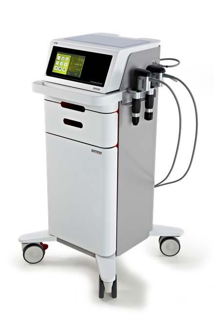
11 1.3 Description of controls and functional elements LCD TFT Touch Screen 2. Connector R-SW/V-ACTOR hand piece channel black 3. Connector R-SW/V-ACTOR hand piece channel yellow 4. R-SW-Handpiece Connector R-SW/V-ACTOR hand piece channel black 2. Connector R-SW/V-ACTOR hand piece channel yellow 11
 4. Mains connector 5. Mains fuse holder 6. Mains switch 7.")
12 USB connector (Type A) 2. Compressed air connector 3. Auxiliary outlet (line out for compressor) 4. Mains connector 5. Mains fuse holder 6. Mains switch 7. Label compressor outlet 8. Read the manual first 12
13 1.4 Description of used marks and symbols See attachment page
14 2 Installation 2.1 Unpacking Remove the equipment and accessories from the packaging container. Proceed with extreme caution Check that all items are included in the packaging container and that they are not damaged. Contact your supplier or the manufacturer immediately if any items are missing or damaged. Retain the original packaging, if possible. It may prove useful for any later equipment transport. 2.2 Scope of supply The standard scope of supply of the ShockMaster 500 includes the following items: ShockMaster 500 (device + trolley) Complete ShockMaster R-SW hand piece + gel holder Mains cable Gel bottle ShockMaster R-SW hand piece (1 metal projectile + tube included) ShockMaster 15mm applicator ShockMaster D-ACTOR 20mm applicator ShockMaster Deep Impact applicator Tissue Box User manual of the ShockMaster 500 (hard copy in English, other languages available on CD) Compressor ShockMaster Revision Kit, metal, User manual of the compressor (hard copy in English) User manual of the hand piece (hard copy in English) Please refer to chapter 6 for information on ACCESSORIES AND SPARE PARTS. 14

15 2.2.1 Connecting the compressed air supply ATTENTION The compressed air input pressure must be bar. If compressors other than the GymnaUniphy S.A. 50 TDC compressor are used, this pressure must be checked on the compressed air supply system. If the pressure exceeds 7.0 bar the system s overpressure protection will be tripped. The compressed air must be dry, oil-free and filtered to 5 micron. Never use CO2 gas for compressed air supply. If compressed air is supplied through a wall outlet, use a pressure reducer (max. 7 bar), if necessary. Connect the compressed air tube to the compressed air connector provided on the compressor. Connect the compressed air tube to the compressed air tube connector provided on the rear side of the ShockMaster 500 until it audibly engages. 15

16 ATTENTION When setting up the unit, make sure that the air outlets on the housing of the ShockMaster 500 are not blocked Connecting the power supply cables An external compressor has to be controlled by the ShockMaster 500 via the mains power link cable. (Compressor Installation: see page 69) Connect the compressor via the mains power link cable to the auxiliary outlet of the ShockMaster 500. (1) Connect the ShockMaster 500 via the mains cable to the mains connector. (2) 2 1 ATTENTION Use both power connectors only for connecting the compressor (1) or Shockmaster 500 (2). Do not connect any other electrical equipment. 16

17 NOTE The compressor is automatically switched on and off with the ShockMaster 500. During first installation make sure that the mains switch of the compressor is in ON position Hand piece connection Connect the connector of the R-SW hand piece to the hand piece connector provided on the ShockMaster 500. ATTENTION Consider the colour marks. Connect the hand piece with the black mark on the cable only with the black output channel. The yellow channel can be used for an extra hand piece or a V-ACTOR. Make sure that the red spots on the connector match the red spots on the hand piece connector. Place the hand piece in the hand piece holder. NOTE Please refer to the separate operating instructions of the hand piece. 17
18 3 Operation 3.1 General warnings and safety information CAUTION The ShockMaster 500 is exclusively intended for use by medical specialists and must only be used by suitably qualified and trained medical personnel (see also chapter 1.2 PRECONDITIONS TO OPERATE THE ShockMaster 500) The user is responsible for correctly positioning the hand piece of the ShockMaster 500. The user is responsible for correctly determining where the treatment zone is located. The ShockMaster 500 must only be used for applications approved by GymnaUniphy. To avoid safety hazards, it is forbidden to use the system for applications other than those specified in chapter INDICATIONS! Do not use the ShockMaster 500 in potentially explosive environments, i.e. in the presence of a flammable anaesthetic mixture with air or with oxygen or nitrous oxide. If systems other than medical devices in accordance with IEC / EN are connected to the ShockMaster 500, such systems must be installed outside the patient treatment area. Cleaning and disinfecting agents may generate an explosive atmosphere. Disconnect the unit and accessories from the mains before starting any cleaning and maintenance work! Do not try to open the system! Risk of electric shocks! 18
19 ATTENTION Check that the installation surfaces have sufficient carrying capacity to avoid equipment damage! Electric medical devices are subject to special regulations regarding Electromagnetic Compatibility (EMC). Hence, medical electric devices must be installed and commissioned in accordance with the EMC guidelines detailed in the accompanying documents. Portable and mobile HF communications equipment (such as cell phones) may cause interferences with medical electric devices. The use of accessories or cabling not authorized by the supplier may cause increased emissions or may lead to reduced interference resistance of the device. The ShockMaster 500 must not be deployed or stored together with other devices. If it is necessary to use the ShockMaster 500 near or together with other devices, it must be tested against that particular environment to ensure operation according to technical specifications. The ShockMaster 500 may be deployed and operated close to the listed accessories. The system must only be connected to properly earthed and correctly installed shockproof sockets! Check that the system is in perfect working order before each use, see chapter 3.4 FUNCTIONAL CHECKS. Never cover the system when in use! Make absolutely sure that no liquid can seep into the system housing or hand piece. Any damage to the unit resulting from incorrect operation is not covered by the manufacturer s warranty. Disposal of the system and its components must be carried out in accordance with national waste disposal regulations. ShockMaster 500 must only be used with accessories that have been approved by the system manufacturer. To prevent safety hazards, unauthorized system modifications are not allowed. This will void the CE mark approval and warranty. 19
20 NOTE The ShockMaster 500 meets the requirements of the applicable electromagnetic compatibility (EMC) standards IEC / EN These limits are designed to provide reasonable protection against harmful interference in a typical medical installation. The equipment generates, uses and can radiate radio frequency energy. If not installed and used in accordance with these instructions, the equipment may cause harmful interference to other devices in the vicinity. However, there is no guarantee that interference will not occur in a particular installation. If this equipment does cause harmful interference with other devices, (this can be established by turning the equipment off and on), users should try to correct the interference by means of one or more of the following measures: Reorient or relocate the receiving device. Increase the separation between the equipment. Connect the equipment into an outlet on a circuit different from that to which the other device is connected. Consult the manufacturer or field service technician for help. 3.2 Operation The user interface Introduction The user interface is divided into 1 main screen (home/treatment-screen) and 5 menu screens. When switching on the device, you automatically enter the main screen (treatment screen). You can use the 5 control buttons at the bottom of the screen to display a menu. 20
21 Control button to activate the Indications List screen Control button to activate the Classic Indications screen Control button to activate the Myofascial Indications screen Control button to activate the Own Indications List screen Control button to activate the Sports Indications screen Control button to activate the Body Area screen Control button to activate Patient Database screen Control button to activate Information screen Control button to activate Settings screen 21
 For each indication there is a picture of the treatment.")
22 Treatment/Home screen The treatment screen consists of 2 parts. The parameters are shown on the right-hand side of the treatment screen. You can upload a pre-programmed set of parameters from the list of indications (please check chapter Indication lists) For each indication there is a picture of the treatment. When loading an indication the picture will appear on the left-hand side of the treatment screen. 22

23 Parameters The following parameters can be set: Pressure: Number of shocks: Frequency: 1 5 bar Adjustable by steps of 0.1 bar shocks adjustable by steps of: - 1 shock between 1-10 shocks - 10 shocks between shocks shocks between shocks >9.900 appears = unlimited amount of shocks Hz (V-ACTOR : 0,5 35 Hz), adjustable by steps of: Hz for a frequency lower then 1Hz - 1 Hz for a frequency higher then 1Hz The frequency of 35 Hz can be set at any moment but will only be active when using the V- ACTOR. If you use the hand piece, the frequency will be automatically reset to 21 HZ, the maximum frequency for the use of the hand piece. The reset button can be used to reset the number of actual shocks to 0. During the treatment you can adjust the parameters. During the treatment you can NOT activate another menu. Below the parameter Number of shocks is a bar with LEDs. On this bar, LEDS will light up to indicate (in %) how many shocks of the total number of shocks assigned have already been given. 23

24 Treatment pictures of an uploaded indication When loading a pre-programmed indication (see page. 27) the corresponding picture will show up on the left-hand side of the treatment screen. Pre-programmed indication picture: Treatment area is marked in blue 1/3 indicates the first of 3 sequences in total for the particular pre-programmed indication For example: Sequence Indicates how many pictures per sequence are available. During the therapy the pictures can be changed by touching the picture field. For example: Picture


 are based on the experiences of medical")

25 - The preferred applicator will be shown in the left-hand corner of the picture. If you press on the applicator s picture field, the name of the applicator will appear. - The name of the chosen indication will appear in the top left-hand corner. If the name is too long it will be not be shown completely unless you press on the name field. - Reset by pressing the home button. NOTE The pre-programmed parameter-settings (indications) are based on the experiences of medical experts or physiotherapists. They are indicative and can be used as an example, but can also be adjusted to one s own expertise. Attention: at the risk of the operator! Indication lists The first button is the Indications List. An indication consists of pre-programmed parameter settings and an image illustrating the treatment. 25

26 The following buttons are located on the right-hand side of the Indication screen: - New: Add a new indication. A new screen will appear. You can name the new indication in this screen. Press for the screen where you can set the corresponding parameters. Press for the screen where you can add extra comments about the indication. New indications are visible in the Indication list if you have saved by pressing. 26

 o Preferred (and alternative) applicator Press to go to the next sequence information screen.")

27 The new indications are written in blue letters. - Info: This screen will provide you with more detailed treatment information about the selected indication. The info is divided in the numbers of sequences for the selected indication. Every sequence provides information about: o Title of the sequence o Treatment information o Parameter settings o Treatment pictures (the number indicates the number of pictures for that sequence) o Preferred (and alternative) applicator Press to go to the next sequence information screen. - Load: The indication you have selected will be loaded and the treatment screen will pop up automatically. The name of the indication you have selected will come into view at the top left-hand corner of the screen. The parameters are set and the corresponding image(s) will be shown on the left-hand side of the screen. - Edit: A screen, similar to the New Indication screen, will be opened. All data are already filled out. It is now possible to modify these data, but you can only change indications that you have added yourself. Standard indications cannot be modified. 27


28 - Delete: It is only possible to delete indications that you have added yourself. Standard indications cannot be deleted. A pop-up screen will ask for a confirmation. You can confirm or cancel. Press A new pop-up will appear asking whether or not to archive the indication. You can confirm or not. If you do not confirm, the indication will be permanently deleted. Archive an indication: An archive button is located in the lower corner.. Select an indication and press. The archive menu will appear on the right-hand side. Press and the indication will appear in the archive. 28


29 De-Archive an indication: Press. Select the indication that you want to de-archive. Press. The indication will appear once more in the indication list. Delete an indication in the archive Press Select the indication that you want to delete and press. A pop-up will appear to confirm the delete action. 29


30 Confirm by pressing. The indication will be deleted. Quick search The quick search button is located in the bottom corner. Press the button. An alphabetical screen will appear on the left-hand side of the screen. Type the first letter of the indication you want to look for and the indication list will go to the indications, starting with the particular letter. Close the quick search tool by pressing on the X or on an indication in the list. 30

31 Filter function The filter button is located bottom corner. In order to find a certain type of indication more quickly, it is possible to show/hide every type of indication. You can select a filtered list by selecting the specific type of indication in the main menu or via the filter panel in the indication menu. The Filter panel is displayed when the user pushes on the Filter symbol. 31


32 Body area The Body Area menu. The buttons are linked to several body areas. Each body area contains several indications. After selecting a body area, a pop-up screen will appear. For example press the Shoulder button: Each indication is supported with an anatomical image related to the indication s muscle area. Select the desired indication, and press or double tap on the name of the indication. The program will then go immediately to the Treatment Menu. No indication can be added or deleted. There is no possibility to check more information on a selected indication. It is also not possible to add new indications. 32

33 Patient database The Patient database menu. It looks and operates like the Indication menu. You can find the following buttons on the right-hand side of the Patient database screen: - New: Add a new patient. A new screen will appear. In this screen you can fill in all general information about the patient. Press to go to the next screen. Press to confirm. The Patient database will appear with each new patient selected. 33


34 - Info: - The screens give all information on the selected patient: The information is shown in 3 screens: o o List of saved treatment data General information about the patient 34


35 In the screen of saved treatment data you can select an indication to see more information about the treatment. o Pain evolution via VAS Select the Vas Score diagram and press. You will see the evolution of the patient s pain during the therapy. To go back to the patient database press, to go back to the previous screen press. o Treatment date Select a treatment date to see all parameter settings and applicators you have used during the treatment session. To go back to the patient database press press., to go back to the previous screen 35


36 - Load: Load the selected patient. A screen will appear where you can select the indication you want to treat. o A previous indication This indication will be positioned underneath the list. Double tap or confirm by pressing. A screen will appear to fill in the VAS (visual analogue scale) to measure pain. The patient can move the slider according to what they are feeling. A VAS is a pain measurement instrument that tries to measure a characteristic or attitude that is believed to range across a continuum of values and which cannot easily be directly measured. Operationally a VAS is usually a horizontal line, 100mm in length. The patient marks the point that they feel represents their perception of their current state on the line. 36
37 When you have changed the VAS a will appear next to the title Vas score. Press on the to go to the next screen. The VAS score will be confirmed by doing this. The symbol will appear at the left side. You will then automatically go to the treatment screen with the parameter settings you ended with in the previous treatment. Complete the treatment according to your own insight. If you want to save the treatment press. A pop-up will appear to confirm. After confirmation, all treatment data will be saved with your patient and you will automatically return to the Home screen. 37

38 When pressing the home button a pop-up will appear to ask if you wish to exit the treatment without saving the data. If you confirm, you will go immediately to the Home screen. o A new indication If you want to treat a new indication with this patient you can select an indication through: The indication list The body area Click on the Indication list or Body area (see previous chapters in the manual) to load the program. The first time you will have to select either the left or right side, depending on the side that you are going to treat. 38
.")
39 When you have selected a side by pressing Left or Right a will appear next to the title Side. Press to confirm your selection. The symbol will appear at the left side of the title Side. A process similar to previous indication will then take place (see page 36). o A new indication via Free Indication You will automatically see a screen where you will have to choose the left or right side. The next step is also the VAS score 39
40 After confirming and pressing the following screen will appear Here you can customize your treatment plan. For every sequence you can select the applicator by tapping on it and setting the parameters. After you stop the treatment or finish the amount of pulses you have set, a will appear to install the next sequence. 40
41 Press to go to the next sequence. In sequence 2, 3, up until 10 you can repeat the same action. Save or close the treatment by using or. You will then go automatically to the Home screen. - Edit: Similar screens as new patient but all data are already filled in. These data can be edited. - Delete: Delete the selected patient. A pop-up screen will appear asking if you wish to delete the patient. Confirm or deny. Archive/ Quick search. This contains options for archiving patients or conducting a quick search of a patient in the list similar to those in the Indication List (see page 25). 41


42 Information Menu The 4 th menu is the Information menu. At the right side of the screen you will find 4 submenus: Application submenu This menu is activated when going into the Information menu. - Applicator Information screens about all applicators will appear. - Application Information about the application of shockwave therapy will appear. 42


43 - Setting parameters Information about how to handle the parameter setting will appear. Medical information submenu The standard indication list will appear. When selecting an indication, basic medical information about this indication will appear. 43


44 Anatomical library submenu Select the body area for which you want to display information. After selection, a pop-up screen will appear. If you select a muscle the following information will be made available: Origin Insertion Action Innervation Arterial Supply If you select a ligament or joint, an anatomical picture with detailed information will pop up. 44


45 This information is only available in English. Contra-Indication submenu Absolute and relative contra-indications and side effects will appear Settings menu The Settings menu. In this menu, all device settings can be changed. 45
46 The menu structure is as follows: 1 Info Software version number Critical parts of device Counter of the total number of pulses 2 Language German English Spanish French Italian Dutch Turkish Danish Czech Polish Russian Portuguese Swedish Norwegian Chinese 3 Time Date and time 4 Hand piece Black - Number of shocks on channel Black - Reset button to put on 0 5 Hand piece Yellow - Number of shocks on channel Yellow - Reset button to put on 0 6 V-Actor - Number of shocks done by the V-Actor - Reset button to put on 0 7 Patient data - Patient Import - Patient export 8 Soft Start - bar/sec - Patient data If you want to make a backup of patient data: Insert an empty USB memory stick in the USB port at the back of the device. Press. If export was successful, the icon will appear next to the export button If export failed, the icon will appear next to the export button. Check if the memory stick is connected properly and empty. 46


47 If you want to make a backup of the patient data: Insert an USB memory stick which contains the patient data. Press. An overwrite warning pop-up will appear: Press to cancel importing. Press to start importing. If import was successful, the icon will appear next to the import button. If import failed, the icon will appear next to the import button. Check that the memory stick is connected properly. - Soft Start: A special Soft start mode enables you to free the pressure gradually up to a certain level or the level at which the patient indicates that maximum tolerance has been reached. You can choose the running up speed of the pressure in the Setting menu. o Minimum level: 0.05 bar/sec o Second level: 0.1 bar /sec with steps of 0.1bar o Maximum level: 1bar/sec Step 1: open the Setting menu and install the soft start time. 47


48 Step 2: Set up the max pressure or choose a pre-programmed indication via Indication List or Body area. Step 3: Activate the soft start mode by pressing. The pressure will start at 1.0 and increase with the chosen speed up to 2.5bar. During the increase the signal will blink. If you want to stop earlier, for example at 1.8 bar, just push the hand piece s trigger button and the device will stop releasing pulses. Activate the trigger button again and the pressure will stay at 1.8 bar. It is always possible to increase the pressure manually by pressing on the plus button Software update - Step 1: Start up the device. - Step 2: Insert the USB stick with the correct data - Step 3: Follow the instructions appearing on the screen - Step 4: Check that you have loaded the correct version Go to the Setting menu and select info. On the screen is indicated: Software version X 48
49 3.3 Start-up NOTE Prior to start-up please refer to the separate operating instructions for the hand piece Switch on the ShockMaster 500 Set the energy of the shocks to an initial value of 2 bar. The maximum pressure is limited to 5.0 bar. The minimum pressure that can be set is 1.0 bar. Press the R-SW hand piece button. If everything is connected properly, shocks are released. Press the hand piece button again and the shock release will stop. 3.4 Functional settings Perform the following functional checks after the system has been installed: Check the control unit and hand pieces for damage. Start the ShockMaster 500 (see chapter 3.3 START UP). Set the energy level to 2.0 bar. Reset the actual number of shocks on the operating panel s parameter display (see Parameters). Release shocks in continuous shock mode (shock frequency 5 Hz/15 Hz). Check that the triggered shocks are correctly counted on the treatment shock counter. 3.5 Standard settings Before each treatment, make sure that the number of shocks and the actual energy value are set to zero. See chapter Parameters Start the R-SW treatment at a pressure of 1.5 bar and a frequency of 8 Hz. 49
50 3.6 Treatment CAUTION Always read chapter 3.1 General warnings and safety information before starting a treatment. Please refer to the separate operating instructions for the hand piece. Each time after the ShockMaster 500 has been transported, make sure that all functional checks have been performed on the unit before you start treatment. To avoid safety hazards, it is forbidden to use the system for applications other than those specified in chapter INDICATIONS! All status and error messages that appear during treatment must always be heeded immediately. NOTE The use of maximal energy level during treatment must not result in any pain or discomfort for the patient! Apply a sufficient amount of coupling gel to the patient s skin in the coupling area and to the R-SW shock transmitter. Perform treatment as described in Indications list Do not apply more than shots to the same spot. Make small circular movements with the hand piece on the place of the indication to avoid this. Avoid excessive pressure by the applicator to patient s skin. Such pressure is not necessary to effect a successful treatment CAUTION Interrupt the treatment after 6000 shocks in R-SW mode at the very latest! Tip of applicator may become hot! 50
51 4 Cleaning, Maintenance and Overhaul 4.1 Cleaning Regular cleaning of the system ensures perfect hygiene and operation of the ShockMaster 500. CAUTION Disconnect the unit and the accessories from the mains before starting any cleaning and overhauling work! Wipe the exterior of the housing with a damp cloth. Use soapy water or a mild cleaning agent. ATTENTION It is essential to prevent fluid penetrating into the unit or its tubes. NOTE Please refer to the separate operating instructions of the hand piece. 51


52 4.2 Replacement mains fuse The holder of the mains fuse is located on the rear panel of the ShockMaster 500. Push the clip of the mains fuse holder to the left and take the holder off the housing. Pull the old fuses out of the fuse holder Replace the fuses with the same type only. Push the fuse holder back into the opening until it engages. 52
53 4.3 Maintenance Preventive maintenance is not necessarily required. However, regular maintenance may help to identify possible defects at an early stage and thus increase the safety and service life of the equipment. Maintenance services can be ordered from our regional representatives in your area or directly from GymnaUniphy. We recommend that functional and safety checks be performed at least once a year. National accident prevention regulations and test and inspection intervals prescribed for medical devices must, of course, be observed. Please pay attention to the separate maintenance instructions for the compressor NOTE For further details on content and performance of the safety checks please contact your local dealer. NOTE The three components ShockMaster 500 device, compressor and the trolley are separately tested by the manufacturer and are each supplied with a safety test report. A recurrent test and test after repair is performed in the complete installation. The conditions and limits apply in accordance to IEC (EN 62353). NOTE Make sure the equipment will checked one a year by an authorized service personnel according test protocol for medical electrical appliances! 4.4 Disposal When disposing of the present medical products, no special measures have to be observed. Please proceed in accordance with the national regulations. After expiration of its life time, dispose the ShockMaster 500 as electronic scrap. For additional information about the disposal of the Sil.Air 50 TDC compressor, please refer to the separate operating manual. 53
54 4.5 Repair Repair work on defective equipment must only be carried out by personnel suitably authorized by GymnaUniphy. Only original GymnaUniphy spare parts may be used for this purpose 54
55 5 Status messages and trouble shooting 5.1 Status messages Control device failure Restart the system. Call your dealer if the problem persists. 5.2 Trouble shooting CAUTION Unplug the mains cable from the system before you carry out any maintenance work! 55
56 Fault description Possible cause Corrective actions System does not work Power failure Defective mains fuse Defective mains cable Check the power supply Replace the fuses Replace the mains cable No compressed air supply Main switch of compressor off connecting cable Leaks on hand piece cable or cable not properly connected Compressed air tube not connected or not correctly fastened with safety coupling Clogged compressor air filter Switch on compressor Check the cable and tube connections and replace them, if necessary. Check the compressor air filter and replace it, if necessary Fault description Possible cause Corrective actions No shockwave power output No compressed air supply Blocked or worn projectile Malfunction in control system Check the compressed air supply Take hand piece apart Clean the guide tube and projectile Overhaul the hand piece Call your dealer Replace the hand piece 56
57 6 Accessories and spare parts 6.1 ShockMaster 500 Compressed air tube Compressed air tube, 1 m long Mains cable Mains cable CEE 7 Europe, 2,5 m long Mains cable CH 3 m long Mains cable USA 3 m long IEC coupling, 1 m long (between control unit and compressor) NOTE For information on the R-SW hand piece and its accessories please refer to the separate operation manual of the R-SW hand piece. 6.2 Compressor S.A.-50-TDC-Compressor S.A.-50-TDC-Compressor, 230 VAC S.A.-50-TDC-Compressor, 115 VAC 57
58 6.3 Accessories ShockMaster 6mm acupuncture applicator ShockMaster 15mm applicator Revision Kit, metal, 17212, ShockMaster ShockMaster D-ACTOR 20mm applicator ShockMaster D-ACTOR 35mm applicator ShockMaster Deep Impact applicator ShockMaster RSWT focus lens set ShockMaster V-ACTOR 25 mm applicator set ShockMaster V-ACTOR 40 mm applicator set ShockMaster V-ACTOR II hand piece (25 and 40 mm applicator included) ShockMaster R-SW hand piece (1 metal projectile + tube included) 6.4 Documentation User manual ShockMaster 500 Accessory Manual R-SW Hand piece Accessory Manual V-ACTOR Hand piece User manual compressor 58
59 7 Technical specifications 7.1 ShockMaster 500 Operating mode R-SW: R-SW: Single shock, 1-21 Hz (1-35 Hz with The V-ACTOR ) Energy selection R-SW: steps of 0.5 bar, from 1 to 5 bars Mains input voltage: 230 VAC / 50Hz (optional 115 VAC / 60Hz) Mains fuse: 10 A H time lag Auxiliary outlet: only for compressor S.A. 50TDC AL Power consumption with compressor: max. 920 VA Compressed air supply: 6-7 bar Compressed air output: 1-5 bar Ambient temperature during operation: 10 C - 35 C Ambient temperature during storage and transport: -20 C 60 C Ambient air pressure: hpa Air humidity: 5% 90%, non-condensing Control unit weight: 8 kg Classification in accordance with MDD 93/42/EEC: IIa Protection against the ingress of water: IPX1 59
 93/42/EEC. 7.")
60 7.2 Identification plate ShockMaster Conformity with directives This medical product bears the CE mark in accordance with the Medical Device Directive (MDD) 93/42/EEC. 7.4 Conformity with standards IEC / EN Type of protection against electric shocks: Class 1 - Degree of protection against electric B shocks:: 60
61 EMC guidance and manufacturer s declaration Guidance and manufacturer s declaration electromagnetic emissions The model ShockMaster 500 is intended to be used in the electromagnetic environment specified below. The customer or the user of the ShockMaster 500 should assure that it is used in such an environment. Emissions test Compliance Electromagnetic environment - guidance RF emissions CISPR 11 Group 1 The ShockMaster 500 uses RF energy only for its internal function. Therefore, its RF emissions are very low and are not likely to cause any interference in nearby electronic equipment. According to IEC this doesn t comply during the generation and release of shockwaves. RF emissions CISPR 11 Harmonic emissions IEC Voltage fluctuations / flicker emissions IEC Class B Class A Complies The ShockMaster 500 is suitable for use in all establishments; including domestic establishments and those directly connected to the public low-voltage power supply network that supplies buildings used for domestic purposes. 61
62 Guidance and manufacturer s declaration electromagnetic immunity The model ShockMaster 500 is intended to be used in the electromagnetic environment specified below. The customer or the user of the ShockMaster 500 should assure that it is used in such an environment. Immunity test IEC test level Compliance level Electrostatic discharge (ESD) IEC Electrical fast transient / Bursts IEC Surge IEC Voltage dips, short interruptions and voltage variations on power supply input lines IEC Power frequency (50/60 Hz) magnetic field IEC ±6 kv contact ±8 kv air ±2kV for power supply lines ±1kV for input/output lines ± 1kV line(s) to line(s) ± 2kV line(s) to earth < 5% U (> 95 % dip in ) for 0.5 cycle 40 % U (60 % T in U ) for 5 cycles 70 % U (30 % dip in U ) for 25 cycles < 5 % U (> 95 % dip in U ) for 5 s ±6 kv contact ±8 kv air ±2kV for power supply lines ±1kV for input/output lines ± 1kV line(s) to line(s) ± 2kV line(s) to earth < 5% U (> 95 % dip in U ) for 0.5 cycle 40 % U (60 % dip in U ) for 5 cycles 70 % U (30 % dip in U ) for 25 cycles < 5 % U (> 95 % dip in U ) for 5 s Electromagnetic environment - guidance Floors should be wood, concrete or ceramic tile. If floors are covered with synthetic material, the relative humidity should be at least 30%. Mains power quality should be that of a typical commercial or hospital environment Mains power quality should be that of a typical commercial or hospital environment. Mains power quality should be that of a typical commercial or hospital environment. If the user of the ShockMaster 500 requires continued operation during power mains interruptions, it is recommended that the ShockMaster 500 be powered from an uninterruptible power supply or a battery. 3 A/m 3 A/m The power frequency magnetic field should be that of a typical commercial or hospital environment. NOTE U is the a.c. mains voltage prior to application of the test level. 62
63 Guidance and manufacturer s declaration - electromagnetic immunity The model ShockMaster 500 is intended to be used in the electromagnetic environment specified below. The customer or the user of the ShockMaster 500 should assure that it is used in such an environment. Immunity test IEC test level Compliance level Electromagnetic environment guidance Portable and mobile RF equipment should be used no closer to any part of the ShockMaster 500, including cables, than the recommended separation distance calculated from the equation applicable to the frequency of the transmitter. Recommended separation distance: Conducted RF 3 Vrms 3 Vrms d = 1,2 P 150 khz to 80 MHz 150 khz to 80 MHz IEC Radiated RF 3 V/m 3 V/m d = 1,2 P 80 MHz to 2,5 GHz 80 MHz to 2,5 GHz 80 MHz to 800 MHz IEC d = 2,3 P 800 MHz to 2,5 GHz Where P is the maximum output power rating of the transmitter in watts [W] according to the transmitter manufacturer and d is the recommended separation distance in metres [m]. Field strengths from fixed RF transmitters, as determined by an electromagnetic site survey a, should be less than the compliance level in each frequency range b. Interference may occur in the vicinity of equipment marked with the following symbol: 63
64 NOTE 1 At 80 MHz and 800 MHz, the higher frequency range applies. NOTE 2 These guidelines may not apply in all situations. Electromagnetic propagation is affected by absorption and reflection from structures, objects and people. a Field strengths from fixed transmitters, such as base stations for radio (cellular/cordless) telephones and land mobile radios, amateur radio, AM and FM radio broadcast and TV broadcast cannot be predicted theoretically with accuracy. To assess the electromagnetic environment with respect to fixed HF transmitters, an electromagnetic site survey should be considered. If the measured field intensity at the location in which the ShockMaster 500 is used exceeds the applicable HF compliance level indicated above, the ShockMaster 500 should be observed to verify normal operation. If abnormal performance is observed, additional measures may be necessary, such as reorienting or relocating the ShockMaster 500. b Over the frequency range 150 khz to 80 MHz, field strengths should be less than 3 V/m. 64
65 Recommended separation distances between portable and mobile RF communications equipment and the ShockMaster 500 The ShockMaster 500 is intended for use in an electromagnetic environment in which radiated RF disturbances are controlled. The customer or the user of the ShockMaster 500 can help prevent electromagnetic interference by maintaining a minimum distance between portable and mobile RF communications equipment (transmitters) and the ShockMaster 500 as recommended below, according to the maximum output power of the communications equipment. Separation distance according to frequency of transmitter [m] Rated maximum output power of transmitter [W] 150 khz to 80 MHz d = 1,2 P 80 MHz to 800 MHz d = 1,2 P 800 MHz to 2,5 GHz d = 2,3 P For transmitters rated at a maximum output power not listed above, the recommended separation distance d in metres [m] can be estimated using the equation applicable to the frequency of the transmitter, where P is the maximum output power rating of the transmitter in watts [W] according to the transmitter manufacturer. NOTE 1 At 80 MHz and 800 MHz, the separation distance for the higher frequency applies. NOTE 2 These guidelines may not apply in all situations. Electromagnetic propagation is affected by absorption and reflection from structures, objects and people. 65
66 7.5 Directives The device complies with the essential requirements of the Medical Devices Directive (93/42/EEC) and the Waste Electrical and Electronic Equipment Directive (2003/108/EC) of the European Parliament and of the Council as most recently changed. 66
67 8 Warranty and service 8.1 Warranty GymnaUniphy and the local GymnaUniphy dealer declares itself to be solely responsible for the correct operation when: all repairs, modifications, extensions or adjustments are performed by authorised people; the electrical installation of the relevant area meets the applicable legal regulations; the equipment is only used by suitably qualified people, according to these user instructions; the equipment is used for the purpose for which it is designed; maintenance of the device is regularly performed in the way prescribed. the technical life time of the equipment and the accessories is not exceeded; the legal regulations with regard to the use of the equipment have been observed. The guarantee period for the equipment is 2 (two) years, beginning on the date of purchase. The date on the purchase invoice acts as proof. This guarantee covers all material and production faults. Wear and tear parts do not fall under this guarantee period. ATTENTION Any unauthorized opening, repair or modification of the system by unauthorized personnel will relieve the manufacturer of its liability and responsibility for safe system operation. This will automatically void the warranty even before the end of the warranty period. 8.2 Service Should you have any further questions or require additional information, please feel free to contact your dealer. 67

68 Attachment Applied part type B CE mark with registration number of the notified body Serial number Article number Main fuse Year of manufacturing Manufacturer Do not dispose this electrical equipment with general house hold waste! Attention, consult the user manual Read the manual! 68


69 Device Installation Preparation of the compressor Fig. 1 Remove red cap (transport protection) Fig. 2 Assemble air filter Fig. 3 Connect air hose (if it is separately) 69


70 Fig. 4 Open the cut off cock ( the red hand gear is perpendicular) Fig. 5 Turn the start switch to position 1 Trolley with compressor Fig. 6 Open the front door at the Trolley 70
 Fig.")


71 Fig. 7 Put the compressor into the Trolley (like it is shown) Fig. 8 Insert the compressor mains plug into the socket of the Trolley Fig. 9 Lay the air hose and the power cord of the compressor upward. Close the front door of the Trolley 71


72 Fig. 10 Connect air hose and power cord to the control unit ShockMaster 500 Emptying of the bottle with condensation water Fig. 11 Open the bottle (with rotary lock) Fig. 12 Empty the bottle, place it into the Trolley and close 72

73 Checking the oil level of the compressor Fig. 13 The oil level is shown by the glass at the backside of the Trolley 73
89 510.")

74 GymnaUniphy NV Pasweg 6A 3740 Bilzen Belgium T +32(0) F +32(0) info@gymna.com Version ( )
PROGRAMMER OPERATIONS MANUAL
 PROGRAMMER OPERATIONS MANUAL Table of Contents Description 4 Installation 4 Operation 5 Safety Precautions 5 Regulatory & Service Information 6 Important Safety and Usage Information 7 Regulatory Notices
User manual. PG89 Rev 01 Editi Pressotherapy model. LymphoPress 4
 User manual PG89 Rev 01 Editi 040515 Pressotherapy model LymphoPress 4 I.A.C.E.R. Srl Via S. Pertini 24/A 30030 Martellago (VE) ITALY Tel. 041.5401356 Fax 041.5402684 e-mail: iacer@iacer.it http://www.itechmedicaldivision.com
Cirrus 5 Oxygen Concentrator Manual
 Cirrus 5 Oxygen Concentrator Manual Important: Make sure you read and understand all of the information JAGZ03-03-3B ver1.0 12/07/2015 contained in this manual before operating your oxygen concentrator!
SC505 Sof Care Inflator. Operating Instructions and Service Manual
 SC505 Sof Care Inflator Gaymar Industries, Inc. 10 Centre Drive Orchard Park, NY 14127 Toll Free +1 800.828.7341 + 1 716.662.2551 Fax +1 800.993.7890 Outside USA +1 716.662.8636 Outside USA Fax +1 716.662.0730
User Manual PTW-DensiX. D / Di/Zi
 User Manual PTW-DensiX D148.131.0/3 2005-05 Di/Zi General Information General Information The product bears the CE-mark "CE-0124" in accordance with the Council Directive 93/42/EEC about Medical Devices
(DynaLaL III) Dynamic True Low Air Loss Mattress Replacement System
 Dynamic True Low Air Loss Mattress Replacement System") (DynaLaL III) User Manual Dynamic True Low Air Loss Mattress Replacement System Alternating + True Low Air Loss Pressure Relief System Manufactured by: Caremed Supply, Inc. Distributed by: Quart Healthcare
(DynaLaL III) User Manual Dynamic True Low Air Loss Mattress Replacement System Alternating + True Low Air Loss Pressure Relief System Manufactured by: Caremed Supply, Inc. Distributed by: Quart Healthcare
Auto*Wave 695 Please read this user manual before starting to use the device.
 Electrical Radial Pressure Pulse Therapy Device Auto*Wave 695 IR9-87 Please read this user manual before starting to use the device.. Rev.B_022817 Mettler Electronics Corp. TABLE OF CONTENTS Foreword 4
Measurement accessories METPOINT OCV for the measurement in systems up to 40 bar
 EN - english Instructions for installation and operation Measurement accessories METPOINT OCV for the measurement in systems up to 40 bar Dear customer, Thank you for deciding in favour of the METPOINT
Theatre Control Panel. Instructions for Use. January 2017 ASF-29 (1)
") Theatre Control Panel Instructions for Use January 2017 0197 ASF-29 (1) Contents 1. Instructions For Use 1.1. Introduction 1.2. Explanation of Symbols 1.3. General Safety Instructions Intended Use Operating
Theatre Control Panel Instructions for Use January 2017 0197 ASF-29 (1) Contents 1. Instructions For Use 1.1. Introduction 1.2. Explanation of Symbols 1.3. General Safety Instructions Intended Use Operating
Pressure Automated Calibration Equipment
 GE Measurement & control Pressure Automated Calibration Equipment Safety Instructions and User Guide - K0447 PACE5000 PACE6000 K0447 Issue No. 9 1 10 1 PACE5000 1 2 3 4 5 PACE6000 2 6 7 8 3 4 5 6 7 8 9
Instruction Manual for Configura Cushionair Portable Pump
 Instruction Manual for Configura Cushionair Portable Pump Fitted with battery powered pump, suitable for Configura Portable chairs V E R S I O N O N E M A Y 2 0 1 6 Contents Introduction 3 Set up of Cushionair
DYNAMIC COMPRESSION THERAPY
 PULSE PRESS DYNAMIC COMPRESSION THERAPY MULTITEC 12 User Manual May 2011 0120 CONTENTS:- SAFETY INSTRUCTIONS ELECTROMAGNETIC INTERFERENCE DESCRIPTION OF CONTROLS MODE SELECTION OPERATING INSTRUCTIONS CARE
POWERPRESS UNIT. User Manual. Gradient Pneumatic Sequential Compressor. Neomedic
 TIMER (MIN) POWERPRESS UNIT 40 70 40 80 90 10 60 100 MIN MAX PRESSURE (mmhg) User Manual Neomedic 9601 Owens mouth Ave. #8 Chatsworth, CA 91311 Toll Free: 866-990-1168 Tel: 818-998-1023 Fax: 818-998-0277
Type Operating Instructions. 2/2-way solenoid valve 2/2-Wege Magnetventil Electrovanne 2/2 voies.
 2/2-way solenoid valve 2/2-Wege Magnetventil Electrovanne 2/2 voies We reserve the right to make technical changes without notice. Technische Änderungen vorbehalten. Sous réserve de modifications techniques.
Med Aire Alternating Pressure Pump and Pad System
 User Manual Med Aire Alternating Pressure Pump and Pad System 14002E 14001E Symbols & Statements NOTE Indicates some tips or some information users should be aware of. CAUTION Indicates correct operating
PRODUCT MANUAL. Diver Smart Interface Cable AS346
 PRODUCT MANUAL Diver Smart Interface Cable AS346 Contact details: Van Essen Instruments B.V. Van Essen Instruments - Canada Delftechpark 20 630 Riverbend Drive, Suite 100 2628 XH Delft Kitchener, ON, The
Sensor for Air Bubble Detection at Liquid Filled Tubes. SONOCHECK Type ABD06.xx. Operating Manual
 Sensor for Air Bubble Detection at Liquid Filled Tubes SONOCHECK Type ABD06.xx Operating Manual Manufacturer: Model: Type: SONOTEC Ultraschallsensorik Halle GmbH Air Bubble Detector ABD06.xx SONOTEC Ultraschallsensorik
User manual. PG132 Rev01 Editi Compressive Limbs Therapy System DVT-7700
 User manual PG132 Rev01 Editi 220114 Compressive Limbs Therapy System DVT-7700 I.A.C.E.R. Srl Via S. Pertini 24/A 30030 Martellago (VE) ITALY Tel. 041.5401356 Fax 041.5402684 e-mail: iacer@iacer.it http://www.itechmedicaldivision.com
OPERATING INSTRUCTIONS FOR USE GUIDE
 AIROS 8 Sequential Compression Device OPERATING INSTRUCTIONS FOR USE GUIDE www.airosmedical.com 1.866.991.6956 Table of Contents Indications for Use & Contraindications...................... 1 Overview
User Manual. PULSE User Manual WARNINGS
 PULSE User Manual PULSE User Manual WARNINGS Table of Contents Warnings 4 Labels 6 Indications for Use 8 Risks and Benefits of the NormaTec PULSE Recovery System 8 Illustrations 9 Operating Instructions
VS18/26 with PROFINET and EtherNet/IP Interface. ATEX Installation Instructions
 VS18/26 with PROFINET and EtherNet/IP Interface ATEX Installation Instructions INDEX 1. INTENDED USAGE 3 2. OPERATING MANUAL ATEX 4 2.1 General conditions 4 2.2 Installation 5 2.3 Operating 5 2.4 Failures
VGP-4300-G. Travel Pulse. Blood Pressure Monitor for Travel
 VGP-4300-G Travel Pulse Blood Pressure Monitor for Travel Congratulations on your Vitagoods purchase. The Travel Pulse Blood Pressure Monitor, will allow you to measure vital blood pressure parameters
ASE SOLVENT CONTROLLER INSTALLATION INSTRUCTIONS Dionex Corporation
 ASE SOLVENT CONTROLLER INSTALLATION INSTRUCTIONS 2000 Dionex Corporation Document No. 031277 Revision 03 April 2000 2000 Dionex Corporation All rights reserved worldwide. Printed in the United States of
CircuFlow 5200 Series
 CircuFlow 5200 Series Sequential Compression Device Operating Instructions www.devonmedicalproducts.com 1.866.446.0092 IFU04.0001 Rev. F 20140522 Intended Use: The CircuFlow 5200 Series Sequential Compression
MODEL Maverick Heavy Duty Aerosol Compressor Operator s Manual
 MODEL 50012 Maverick Heavy Duty Aerosol Compressor Operator s Manual This page left blank intentionally CONTENTS Page No. INSPECTION... 1 GENERAL INFORMATION... 1 SAFETY PRECAUTIONS... 2 BASIC OPERATING
USER MANUAL SAVE THESE INSTRUCTIONS. For the most current manual revision, please visit our Website:
 USER MANUAL Model: PM4300 Series SAVE THESE INSTRUCTIONS For the most current manual revision, please visit our Website: www.precisionmedical.com 300 Held Drive Tel: (+001) 610-262-6090 Northampton, PA
Rigel 601 CHECKBOX. Instruction Manual. 348A551 Issue 2.0. April Seaward Electronic Ltd. Issue 2.0
 Rigel 601 CHECKBOX Instruction Manual 348A551 Issue 2.0 April 2006 2006 Seaward Electronic Ltd. Issue 2.0 Limited Warranty & Limitation of Liability Rigel Medical guarantees this product for a period of
NICE1 Cold + Compression Therapy System
 NICE1 Cold + Compression Therapy System Thank you for choosing the NICE1 Cold + Compression Therapy System. The NICE1 uses advanced technology to greatly improve the convenience and efficacy of cold +
LC-SPE. Organizer 3.0 User Manual. Innovation with Integrity. Version 001 NMR
 LC-SPE Organizer 3.0 User Manual Version 001 Innovation with Integrity NMR Copyright by Bruker Corporation All rights reserved. No part of this publication may be reproduced, stored in a retrieval system,
VENTI-O 2 plus. O 2 switching valve for: VENTImotion from serial number 4000 VENTIlogic from serial number 4000 VENTImotion 2
 VENTI-O 2 plus O 2 switching valve for: VENTImotion from serial number 4000 VENTIlogic from serial number 4000 VENTImotion 2 Device description and operating instructions Overview VENTI-O 2 plus with therapy
Getting to know your Sureshotgps micro V3
 Getting to know your Sureshotgps micro V3 Battery State Symbol Satellite Signal Shows distance to front, centre and rear of each green Hole Number Real Time Power on and Enter Key Down (backward) Key 1
1 METRON MANIPULATION TABLES - WARRANTY STATEMENT
 1 METRON MANIPULATION TABLES - WARRANTY STATEMENT Metron Medical Australia Pty Ltd. will warrant this table, for parts only against defects in manufacture for a period of two (2) years for structural integrity,
Owner s Manual & Safety Instructions
 Owner s Manual & Safety Instructions Save This Manual Keep this manual for the safety warnings and precautions, assembly, operating, inspection, maintenance and cleaning procedures. Write the product s
MAGICFX CONFETTIPISTOL USER AND INSTALLATION MANUAL
 English MAGICFX CONFETTIPISTOL USER AND INSTALLATION MANUAL CONFETTI FX / STREAMER FX Manual trigger PART01129 rev 01-00 DISCLAIMER WARNING Read this manual carefully before installing and/or using this
Budget Range Operators Handbook
 Budget Range Operators Handbook BAMBI AIR COMPRESSORS LTD 152 Thimble Mill Lane Heartlands Birmingham B7 5HT United Kingdom Tel: 0121 322 2299 Fax: 0121 322 2297 Email: sales@bambi-air.co.uk www.bambi-air.co.uk
CircuFlow TM 5150 Series
 CircuFlow TM 5150 Series Sequential Compression Device Operating Instructions www.devonmedicalproducts.com 1.866.446.0092 IFU34.0001 Rev. D 20140313 The Model 5150 - Sequential Compression Device Indications:
JOLLY2. Installation user s manual. 6 different operating modes selectable. version 3.3. DATA TO BE FILLED OUT BY THE INSTALLER (Page 1)
") ENGLISH ENGLISH ENGLISH ENGLISH Installation user s manual Warning! electrical scheme modified JANUARY 2005 version 3.3 JOLLY2 DATA TO BE FILLED OUT BY THE INSTALLER (Page 1) 6 different operating modes
ENGLISH ENGLISH ENGLISH ENGLISH Installation user s manual Warning! electrical scheme modified JANUARY 2005 version 3.3 JOLLY2 DATA TO BE FILLED OUT BY THE INSTALLER (Page 1) 6 different operating modes
EC214 EC215 - EC215R Bench Conductivity Meters
 Instruction Manual EC214 EC215 - EC215R Bench Conductivity Meters http://www.hannainst.com These Instruments are in Compliance with the CE Directives Dear Customer, Thank you for choosing a Hanna Instruments
RPS900W Redundant Power Supply. Installation Guide.
 RPS900W Redundant Power Supply Installation Guide www.edge-core.com Installation Guide RPS900W Redundant Power Supply Single DC Output Port with Dual Output Voltages RPS900W E10013-CS-R01 1500000081A
User Manual. Quantos Automated Dosing Liquid Module
 User Manual Liquid Module 1 Safety Information 1.1 Definition of warnings and symbols Signal Words WARNING for a hazardous situation with medium risk, possibly resulting in severe injuries or death if
Operating Instructions Part No
 DIGITAL AUTOMATIC TYRE INFLATOR Operating Instructions Part No. 11.0578 Thank you for selecting this Jamec Pem Automatic Tyre Inflator. Please read this manual before carrying out any installation or service
CircuFlow TM 5208 Series
 CircuFlow TM 5208 Series Sequential Compression Device Operating Instructions www.devonmedicalproducts.com 1.866.446.0092 IFU35.0001 Rev. E 20140313 Intended Use: The CircuFlow 5208 Series Sequential Compression
Vapotherm Q50 Compressor. Instructions for Use
 Vapotherm Q50 Compressor Instructions for Use Contents Quick Start Guide...2 Intended Use...3 Indications, Warnings and Cautions...4 Primary Indications...4 Contraindications...4 Warnings and Cautions...4
12V Mini Air Compressor
 INSTRUCTIONS FOR 12V Mini Air Compressor Stock No.80999 Part No.DA12/250B IMPORTANT: PLEASE READ THESE INSTRUCTIONS CAREFULLY TO ENSURE THE SAFE AND EFFECTIVE USE OF THIS PRODUCT. GENERAL INFORMATION This
Regalia Oxygen Concentrator
 Regalia Oxygen Concentrator REGALIA INSTRUCTION MANUAL P/N 5167 Rev B January 2014 Table of Contents Warnings and Cautions... 3 Indications for Use... 4 Introduction... 4 Important Safety Instructions...
SkillGuide. User Guide. English
 SkillGuide User Guide English SkillGuide SkillGuide is a feedback device designed to provide real-time and summative feedback on CPR performance. www.laerdal.com Items included SkillGuide and User Guide.
HI 2314 HI 2315 HI 23151
 Instruction Manual HI 2314 HI 2315 HI 23151 Multi-Range Conductivity Meters for Laboratories www.hannainst.com Dear Customer, Thank you for choosing a Hanna Instruments product. Please read this instruction
Gas density monitor With integrated transmitter Model GDM-100-TI
 SF 6 gas solutions Gas density monitor With integrated transmitter Model GDM-100-TI grid Products WIKA data sheet SP 60.05 for further approvals see page 5 Applications Gas density monitoring of closed
F-330 Instruction manual. Magic Glove Bio Skin Smoother High Frequency Ultrasound Galvanic
 F-330 Instruction manual Magic Glove Bio Skin Smoother High Frequency Ultrasound Galvanic Warning Never under any circumstances attempt to open or inspect the internal components or accessories of the
PLEASE READ CAREFULLY BEFORE INSTALLING OR USING MEGA POOL SAVER MPS 1100
 MPS-1100 User Manual Mega Pool Saver Ltd PLEASE READ CAREFULLY BEFORE INSTALLING OR USING MEGA POOL SAVER MPS 1100 For further up to date instructions on how to install Mega Pool Saver MPS 1100, please
Digital Melting Point Apparatus
 Digital Melting Point Apparatus Heating Plateau Ramping Start/Stop Plateau set Ramp stop Hold User Guide Version 1.1 Heating Viewing tube Sample Chamber IEC power inlet socket Power on/off Temperature
e.do Gripper Safety requirements, technical features and assembly and integration instructions
 e.do Gripper Safety requirements, technical features and assembly and integration instructions Requirements, technical features and instructions for safe installation and use of the e.do Gripper. CR00758190-en_00/2018.05
Operating Instructions Temperature Measuring System MF420-5T-100
 Operating Instructions Temperature Measuring System Dnhqdhnjah MF420-5T-100 Dmsklakla Read before use! Observe all safety instructions! Keep for future reference! Fon +49/7221/64103 Fax +49/7221/17103
Portable oxygen concentrator
 Table of contents G3 1. Introduction 2 2. Important Safety Rules 3 3. Unpack your Lovego 4 4. User Controls & System Status Indicators 5 5. Quick Start 6 6. How to operate 7 7. How to operate with battery
User Manual DIRECTHEALTHCARESERVICES.CO.UK
 User Manual DYNA-FORM AIR PRO-PLUS The Dyna-Form Air Pro-Plus is a pressure relieving mattress suitable for use with patients at VERY HIGH RISK of pressure ulcer damage. Offering high levels of patient
KGW - ISOTHERM. Operating Instructions. Level controlling device for liquid nitrogen LEVEL CONTROL LN2
 KGW - ISOTHERM Germany 76185 Karlsruhe Gablonzer Straße 6 Tel. 0049 / 721 / 95897-0 Fax. 0049 / 721 / 95897-77 email:info@kgw-isotherm.de Internet: www.kgw-isotherm.de Operating Instructions Level controlling
MoveRoll Conveyor Operating and Maintenance Manual
 MoveRoll Conveyor Operating and Maintenance Manual 1. Read this first! This manual contains information for protection of personnel in the roll handling area from possible injury and/or equipment damage.
ORB-400 BUBBLE/HAZE MACHINE. Item ref: UK User Manual
 ORB-400 BUBBLE/HAZE MACHINE Item ref: 160.462UK User Manual Caution: Please read this manual carefully before operating Damage caused by misuse is not covered by the warranty Introduction Thank you for
Instruction Manual BA90 Precision Barometer
 Instruction Manual BA90 Precision Barometer halstrup-walcher GmbH Stegener Straße 10 D-79199 Kirchzarten Germany Phone: +49 (0) 76 61/39 63 0 Fax: +49 (0) 76 61/39 63 99 E-Mail: info@halstrup-walcher.com
USER MANUAL. SAVE THESE INSTRUCTIONS (For latest revision, go to
 USER MANUAL Model: PM5950 SAVE THESE INSTRUCTIONS (For latest revision, go to www.precisionmedical.com) Federal (USA) law restricts this device to sale by or on the order of a physician. Tel: (+001) 610-262-6090
STAGE, STADIUM & X-TREME SHOT.
 USER AND INSTALLATION MANUAL ENGLISH STAGE, STADIUM & X-TREME SHOT. CONFETTI & STREAMER FX PART01339 rev 01-00 DISCLAIMER WARNING Read this manual carefully before installing and/or using this product.
REF R00 JH 02/04/11 USER MANUAL
 REF 1082564 1082563 R00 JH 02/04/11 USER MANUAL UltraFill User Manual Table of Contents Introduction...3 How the System Works...7 Troubleshooting Guide... 19 Cleaning and Maintenance... 22 Transporting
Operating instructions Safety Rope Emergency Stop Switches ZB0052 / ZB0053 ZB0072 / ZB0073
 Operating instructions Safety Rope Emergency Stop Switches UK ZB0052 / ZB0053 ZB0072 / ZB0073 7390878 / 02 03 / 2011 Contents 1 Safety instructions...3 2 Installation / set-up...4 2.1 Applications...4
PitchTracker User Guide. Model: DKPT01 User Guide
 PitchTracker User Guide Model: DKPT01 User Guide PACKAGE CONTENTS What Comes in the Box USING YOUR SMART BALL Turn On Your Smart Ball Pair your Smart Ball Turn Off Your Smart Ball Charge your Smart Ball
CJMJ.DPNQBDU. Instruction for use. Neonatal phototherapy device. BILI-COMPACT WY 1816/ Year of manufacture D2017_00
 Instruction for use Neonatal phototherapy device CJMJ.DPNQBDU D2017_00 GmbH > BILI-COMPACT WY 1816/ Year of manufacture Herrenhöhe 4 D-51515 Kürten/Germany 02207-9698-0 02207-4750 E-mail: info@weyermed.com
HoverJack. Air Patient Lift. User Manual. From HoverTech International.
 HoverJack Air Patient Lift From HoverTech International User Manual www.hovermatt.com Table of Contents Symbol References... 02 Intended Use and Precautions... 03 HOVERJACK Introduction... 04 Part Identification
Sensor. Directions For Use
 Nasal Alar SpO2 Sensor Directions For Use Emergo Europe Prinsessegracht 20 2514 AP The Hague The Netherlands Manufactured by: Xhale Assurance, Inc. 3630 SW 47th Ave., Suite 100 Gainesville, FL 32608, USA
PRAHER PLC-MP AQUASTAR MANAUL 2009
 PRAHER PLC-MP AQUASTAR MANAUL 2009 1. Copyrights This Operating Manual contains copyright-protected information. All rights reserved to Praher Kunststofftechnik GmbH. This Operating Manual is designed
OPERATOR s MANUAL AHCON PCI 3000
 OPERATOR s MANUAL AHCON PCI 3000 1 INDEX Page Manufacturer s Information 3 Warnings 4 Risks and Labelling 5 Safety Precautions 5 Warranty 6 Dimensions and Weight 7 Shipping Dimensions 7 Connection 8 Operation
D10S/D20S Wall/Post Mount Inflator Quick Start Manual
 PART NUMBER SERIAL NUMBER D10S/D20S Wall/Post Mount Inflator Quick Start Manual Please read and save these instructions. Read carefully before attempting to assemble, install, operate or maintain the product
VERTICAL AIR COMPRESSORS
 VERTICAL AIR COMPRESSORS MODEL NO: VE15C150, VE18C150, VE25C150 PART NO: 2226010, 2226020, 2226025 OPERATION & MAINTENANCE INSTRUCTIONS LS0715 INTRODUCTION Thank you for purchasing this CLARKE Vertical
Oxygen Dialflow Meter. Instructions for Use
 Oxygen Dialflow Meter Instructions for Use 702-0031.12 December 2017 1. Symbols Warning! Caution! Indicates a potentially hazardous situation which, if not avoided, could result in injury to the patient,
User manual. MNPG 102 Rev. 04 Edition 04/02/16. Pressotherapy model. Power-Q1000 Premium
 User manual MNPG 102 Rev. 04 Edition 04/02/16 Pressotherapy model Power-Q1000 Premium I.A.C.E.R. Srl Via S. Pertini 24/A 30030 Martellago (VE) ITALY Tel. 041.5401356 Fax 041.5402684 e-mail: iacer@iacer.it
AT4 Tourniquet System Operating Instructions
 AT4 Tourniquet System Operating Instructions Rx ONLY AT4 Pneumatic Tourniquet Reference No. 40070 AT4 Electronic Tourniquet Reference No. 40080 0473 92410/6/230615 Page 1 92410/6/230615 Page 2 Contents
! Warning, refer to accompanying documents.
 About this Manual To the best of our knowledge and at the time written, the information contained in this document is technically correct and the procedures accurate and adequate to operate this instrument
12V MINI AIR COMPRESSOR
 12V MINI AIR COMPRESSOR STOCK No.65958 PART No.DA12/250A INSTRUCTIONS IMPORTANT: PLEASE READ THESE INSTRUCTIONS CAREFULLY TO ENSURE THE SAFE AND EFFECTIVE USE OF THIS TOOL. 08/2001 GENERAL INFORMATION
Welcome to the World of In-Home Gardening! Simple Steps to Get Your AeroGarden Up and Growing (No Tools Required)
") Quick Setup Guide Welcome to the World of In-Home Gardening! Simple Steps to Get Your AeroGarden Up and Growing (No Tools Required) Harvest Model number: 100690-BLK / GRY / WHT / RED Harvest 360 Model
Quick Setup Guide Welcome to the World of In-Home Gardening! Simple Steps to Get Your AeroGarden Up and Growing (No Tools Required) Harvest Model number: 100690-BLK / GRY / WHT / RED Harvest 360 Model
Welcome to the World of In-Home Gardening! Simple Steps to Get Your AeroGarden Up and Growing (No Tools Required)
") Quick Setup Guide Welcome to the World of In-Home Gardening! Simple Steps to Get Your AeroGarden Up and Growing (No Tools Required) Harvest Elite Model number: 100691-PPL / BSS / PCP / PSG Harvest Elite
Quick Setup Guide Welcome to the World of In-Home Gardening! Simple Steps to Get Your AeroGarden Up and Growing (No Tools Required) Harvest Elite Model number: 100691-PPL / BSS / PCP / PSG Harvest Elite
Air Plus User Manual
 Air Plus User Manual Alternating pressure mattress for prophylaxis and treatment of pressure sores Indications for use The Air Plus has been developed as a state of the art pressure relieving system for
The Univentor 1250 Anaesthesia Unit
 THE UNIVENTOR 1200/1250 ANAESTHESIA UNIT The Univentor 1250 Anaesthesia Unit TABLE OF CONTENTS EDITION 1 Section 1 - WARRANTY & SERVICE 1.1. WARRANTY 2 1.2. DAMAGED SHIPMENTS 2 1.3. SERVICE 2 Section 2
Pneumatic high-pressure controller Model CPC7000
 Calibration technology Pneumatic high-pressure controller Model CPC7000 WIKA data sheet CT 27.63 Applications Automotive and avionics industry Industry (laboratory, workshop and production) Transmitter
CONSOLE-320 ENGLISH. 230A: CONSOLE-320 with cable data output Item 230B: CONSOLE-320 with cable + wireless radio data output
 CONSOLE-320 Item 230A: CONSOLE-320 with cable data output Item 230B: CONSOLE-320 with cable + wireless radio data output Table of contents 1. INTRODUCTION...2 1.1 Power supply...2 1.2 Connections...2 1.3
MP15 Jockey Pump Controller
 Setup and Operating Instructions MP15 Jockey Pump Controller This manual provides general information, installation, operation, maintenance, and system setup information for Metron Model MP15 Jockey Pump
KERN EG/EW Version /02
 E KERN EG/EW Version 1.5 07/02 Operating Instructions Electronic Precision Balances Contents 1 TECHNICAL DATA... 20 2 UNPACKING AND STANDARD ACCESSORIES... 23 3 SETTING UP THE BALANCE... 23 4 EXTERNAL
Instruction Manual Dräger MSI P7 and MSI P7 plus
 Dräger MSI GmbH Rohrstraße 32 58093 Hagen Tel.: +49-2331 / 9584-0 Fax: +49-2331 / 9584-29 e-mail: info@draeger-msi.de D 923; Edition 2011-01-01 Content 1. General Hints Page 4 2. The Instrument 2.1 Front
77-I0PN230 Rev. A. Model 1030 User Manual
 77I0PN230 Rev. A TABLE OF CONTENTS FUNCTION...2 TREATMENT...3 INDICATIONS FOR USE...4 CONTRAINDICATIONS...4 CLEANING...4 MAINTENANCE...4 CLASSIFICATION & SYMBOLS...4 DISINFECTION / STERILIZATION...4 SAFETY
Simplified Automated Ventilator Training Slides
 Simplified Automated Ventilator Training Slides Export Department: J.D. Honigberg International, Inc. 155 N. Pfingsten Road, Suite 150 Deerfield, IL 60015 USA Tel: 847-412-0200 Email: medical@jdhintl.com
Resusci Anne Simulator
 EN Resusci Anne Simulator Important Product Information www.laerdal.com Cautions and Warnings A Caution identifies conditions, hazards, or unsafe practices that can result in minor personal injury or damage
Intermittent Pneumatic Compression System
 User Manual Intermittent Pneumatic Compression System To ensure safe use of this device, it is essential that you read and fully understand the information contained within this manual. Mechanical prophylaxis
OC4000 USER'S GUIDE I O OXYGEN CONCENTRATOR FOR VETERINARY USE ONLY. by Supera Anesthesia Innovations GLOSSARY OF SYMBOLS. : ON (power switched on)
") by Supera Anesthesia Innovations USER'S GUIDE OC4000 OXYGEN CONCENTRATOR FOR VETERINARY USE ONLY I O : ON (power switched on) : OFF (power switched off) : Class II protection : Do not expose to open flames
by Supera Anesthesia Innovations USER'S GUIDE OC4000 OXYGEN CONCENTRATOR FOR VETERINARY USE ONLY I O : ON (power switched on) : OFF (power switched off) : Class II protection : Do not expose to open flames
OptonPro. High-power laser up to 7000 mw. Laser therapy natural healing with the power of light
 GB High-power laser up to 7000 mw Laser therapy natural healing with the power of light Application of high-power light for targeted penetration of high amounts of energy deep into the tissue. Initiates
Comfortmax Thermax Hot/Cold Water Circulation System. Instructions for Use
 Comfortmax Thermax Hot/Cold Water Circulation System Instructions for Use THIS DEVICE CAN BE COLD ENOUGH TO CAUSE SERIOUS INJURY. SERIOUS ADVERSE REACTIONS AND SAFETY HAZARDS MAY OCCUR WHEN USING THIS
Operating Instructions Part No
 DIGITAL AUTOMATIC TYRE INFLATOR Operating Instructions Part No. 11.0545 Thank you for selecting this Jamec Pem Automatic Tyre Inflator. Please read this manual before carrying out any installation or service
PitchTracker Softball User Guide
 PitchTracker Softball User Guide Model: DKPTS01 User Guide PACKAGE CONTENTS What Comes in the Box USING YOUR SMART SOFTBALL Turn On Your Smart Softball Pair your Smart Softball Turn Off Your Smart Softball
Type 0404 / /2-way solenoid valve 2/2-Wege-Magnetventil Électrovanne 2/2 voies Operating Instructions Bedienungsanleitung Manuel d utilisation
 Type 0404 / 5404 2/2-way solenoid valve 2/2-Wege-Magnetventil Électrovanne 2/2 voies Operating Instructions Bedienungsanleitung Manuel d utilisation 1 OPERATING INSTRUCTIONS The operating instructions
Paradise Pump Series Operator s Manual
 Paradise Pump Series Operator s Manual P/N 12421-000 9/05 Paradise Pump Operator s Manual Important Before using the Paradise Pump Alternating Pressure Relief Systems, please read and understand this
Instruction manual. for. high purity gas pigtails 200 bar / 300 bar
 Instruction manual for high purity gas pigtails 200 bar / 300 bar Contents Contents... 2 1. Preface... 3 1.1 Overview... 3 1.2 General... 3 1.3 Intended use... 4 1.4 Personnel requirements... 4 2. For
OPERATION MANUAL PNEUMATIC VALVES
 OPERATION MANUAL PNEUMATIC VALVES DIRECTIVE 2014/34/EU ATEX ENGLISH Index 1 Product identification 2 Security 3 Guarantee 4 Transportation 5 Assemblage 6 Setting up 7 Adjustments 8 Technical information
A4s Operation Manual
 A4s Operation Manual Safety Instruction Please read this manual carefully, also with related manual for the machinery before use the controller. For installing and operating the controller properly and
Operating Manual Body fat balance
 KERN & Sohn GmbH Ziegelei 1 D-72336 Balingen email: info@kern-sohn.com Phone: +49-[0]7433-9933-0 Fax: +49-[0]7433-9933-149 Internet: www.kern-sohn.com Operating Manual Body fat balance KERN MFB Version