Press. Press Fit System Technical Guide. conexbanninger.com.au
|
|
|
- Cora Allison
- 6 years ago
- Views:
Transcription

1 >B< Press Press Fit System Technical Guide conexbanninger.com.au
2 100 Years of Innovation For more than 100 years, Conex Bänninger has been the recognised leader in plumbing fittings, accessories and valves globally offering a range of innovative and highly versatile jointing solutions. Since opening its doors in Giessen, Germany in 1909, Conex Bänninger has produced over 20 billion copper fi ttings, establishing an unrivalled reputation for outstanding quality, fi rst class customer service and market leading expertise. Passionate about excellence, Conex Bänninger is the name professionals trust for domestic, commercial, industrial, air conditioning and refrigeration applications worldwide. Conex Bänninger is an ISO 9000 assured company, which assures you the very best in quality. Fast Facts 20 billion fittings sold worldwide since 1909 Conex Bänninger >B< mark introduced in staff working across the globe Produce 500 million pieces a year


3 Contents Key Features 4-5 Applications 6-7 Approvals and Certification Technical Data Fittings 15-50mm 15 X Fittings mm 41 Installation Requirements 59 Tools 65 FAQs 74-77
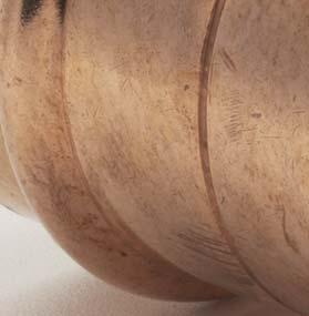
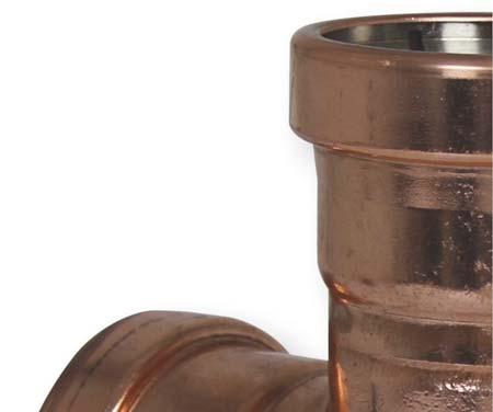
4 Key Features Conex Bänninger >B< Press is a versatile press fitting system for use with hard, half hard or annealed copper tube providing a secure, life long, leak-proof joint. >B< Press fi ttings are quick to fi t, providing a low cost installation solution. The slimline design gives an aesthetically pleasing fi nish with a secure, permanent joint that can t be tampered with. >B< Press Water fi ttings are Watermark approved and certifi ed to AS3688. >B< Press Gas fi ttings are OceanaMark approved and certifi ed to AS3688. AS 3688 ic No.WM Conex Bänninger >B< Press Technical Guide
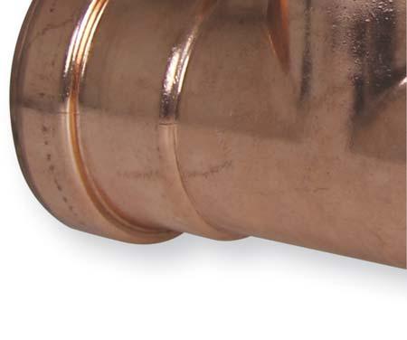
5 Flame free Flame free installation takes away risk of fi re on site. Reliable simplicity Simple, quick and reliable installation provides low installed cost. Fully certified Extensive third party certifi cation offers peace of mind to the client, specifi er and installer. Performance Corrosion resistant and with a design life of 50 years, >B< Press can be relied on to perform long after installation. Slimline profile Slimline, unobtrusive design provides aesthetic fi nish. Permanent joint Secure, permanent joint crimped both sides of deep set O-ring ensures fi tting cannot be tampered with. Practical by design ead-in edge aids installation and helps protect O-ring from damage or displacement. eak Indicator The unique pressing indicator in the O-ring shows leaks at low pressures when fi ttings are not pressed. Conex Bänninger >B< Press Technical Guide 5
6 Applications & Warranty 6 Conex Bänninger >B< Press Technical Guide
 Fuel lines >B< Press High Temperature Fittings are suitable for: Solar hot water")

 where competitor fi ttings")
7 Applications >B< Press Water Fittings are suitable for: Drinking water Heating water (non solar) Chilled water >B< Press Gas Fittings are suitable for: Natural and PG Compressed air (with or without oil content) Fuel lines >B< Press High Temperature Fittings are suitable for: Solar hot water Warranty A 25 year warranty covers against faults caused by defective manufacture of the fi ttings. It does not cover faults arising from incorrect installation. The warranty covers installation with type A and B copper tube conforming to AS1432 but does not cover any faults arising from competitor fi ttings used on the same installation nor faults caused by damaged >B< Press fi ttings (through excessive pressure, for example) where competitor fi ttings created non-compliant conditions. All >B< Press fi ttings must be installed by a licensed plumber. Conex Bänninger >B< Press Technical Guide 7
8 Approvals & Certification 8 Conex Bänninger >B< Press Technical Guide


9 WATERMARK ICENCE IAPMO R&T Oceana hereby grants to: Conex Universal imited Global House, 95 Vantage Point The Pensnett Estate, Kingswinford, West Midlands DY6 7FT United Kingdom Certification Conex Bänninger is an ISO 9000 Quality assured company. In addition to Watermark approvals in Australia, Conex Bänninger has approvals from numerous national and international bodies including DVGW, KIWA, GASTEC, WRAS and AENOR, plus many well-known others. Conex Bänninger >B< Press Technical Guide 9
10 Technical Data >B< Press is suitable for use with hard, half hard or annealed type A and B copper tube complying with AS1432 Water Supply Systems Application / Medium Comments Hot and cold potable water Fire Services Australian Watermark approved. Watermark certifi cation for all plumbing products is restricted to 1400kPa at 95 C. Capable of the required test pressure of 1700kPa or 1.5 times the design pressure as specifi ed by AS Rainwater Pump circulated hot water systems Compliant with EN Chilled Water Steam ow pressure steam equipment Solar Collectors Conditioned water (partially and fully desalinised water, softened, deionised demineralised distilled) Anti-Freeze / Corrosion Protection / Inhibitors Application / Medium Anti-freeze cooling concentration 50% Product Antifrogen N Antifrogen Antifrogen Sol (solar systems) Ethylene Glycol (Ethan-1,2-diol) Propylene Glycol (1,2-Propandiol) Tyfoxit Tyfocop Antifrogen N Antifrogen Antifrogen Sol (solar systems) Ethylene Glycol (Ethan-1,2-diol) Propylene Glycol (1,2-Propandiol) Tyfoxit Tyfocop Comments Manufacturer Clariant Clariant Clariant Various Various Tyforop-Chemie Tyforop-Chemie Clariant Clariant Clariant Various Various Tyforop-Chemie Tyforop-Chemie Indicates compatibility. (Consultation required for unlisted mediums) *Note: Installations need to comply to the relevant standards and local regulations. The maximum constant or standard operating pressure and temperature are shown. For testing or short spikes higher pressure and temperature may be applicable. 10 Conex Bänninger >B< Press Technical Guide
11 P (kpa) T ( C) >B<Press Water >B<Press Gas >B<Press HT Ambient Not compatible P (kpa) T ( C) >B<Press Water >B<Press Gas >B<Press HT to to 160 Conex Bänninger >B< Press Technical Guide 11
12 Technical Data >B< Press is suitable for use with hard, half hard or annealed type A and B copper tube complying with AS1432 Oils, cooling materials and lubricants Application / Medium Engine oils and ubricants (Petroleum-based) Engine Oils (Synthetic based) Bio Diesel Heating oil, Diesel in acc. with EN590 Comments Consultation required Gas Application / Medium Compressed Air Natural Gas iquid gas Propane Butane Methane Argon Forming Gas, Dry / Welding Inert Gas Vacuum Comments Oil Concentration < 25mg/m³ Oil Concentration > 25mg/m³ The scope of AS5601 for all gas systems is restricted to 200kPa. For welding Ar+CO 2 (Eg Cargon) Carbon Dioxide (Dry Gas) Dry CO 2 Carbon Dioxide (Wet Gas) Nitrogen Nitrogen Gas Helium May leak at <0.001cm³ /min Neon Xenon Synthetic Air Krypton Oxygen Acetylene Hydrogen Carbon Monoxide X not compatible Special Media Application / Medium Acetone Condensate Condensate Ethanol Urea Methanol Sodium Hydroxide Ammonia Comments iquid From gas condenser boiler From steam 12 Conex Bänninger >B< Press Technical Guide
13 Indicates compatibility. (Consultation required for unlisted mediums) *Note: Installations need to comply to the relevant standards and local regulations. P (kpa) T ( C) >B<Press Water >B<Press Gas >B<Press HT Not compatible to 40 P (kpa) T ( C) >B<Press Water >B<Press Gas >B<Press HT to Ambient 1600 Ambient Not compatible Ambient Not compatible P (kpa) T ( C) >B<Press Water >B<Press Gas >B<Press HT to Not compatible Not compatible Not compatible Not compatible Conex Bänninger >B< Press Technical Guide 13


14


15 Fittings 15-50mm

 B.")
 3 4 4.")
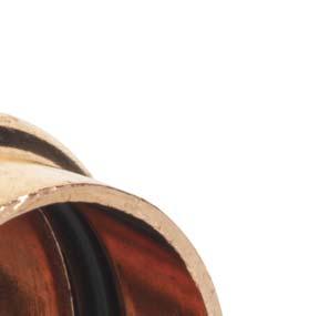
16 Product Features O-Ring >B< Press fi ttings for water applications are identifi ed with a black O-ring. For natural gas and PG applications, fi ttings are identifi ed by a yellow coloured O-ring and a yellow mark on the fi tting body. *Important Note: The O-ring colour and identifi cation must meet the application. O-ring in the fi ttings are not to be removed or changed. A B C A. Specialist O-ring (Gas HNBR) B. Specialist O-ring (Water EPDM) C. Specialist O-ring (High Temperature - FKM) 1 2 Section through >B< Press fi tting 1. Bead 2. O-ring 3. Cylindrical sleeve (socket) Pressing both sides of O-ring Water EPDM Gas HNBR High Temperature FKM 16 Conex Bänninger >B< Press Technical Guide
17 Pressing Indicator (PI) Feature The unique pressing indicator is a specially designed O-ring. It has a reduced section in two positions that allows water or air past the sealing element of any unpressed connection, thereby providing a visible leakage point during the commissioning of the system. Unpressed fi ttings are identifi ed by pressurizing the system with a pressure range of 100 kpa to 500 kpa for water (prior to the fi nal pressure testing) and 2.2 kpa to 300 kpa for gas. When the fi tting is pressed, the O-ring material compresses, fi lling the gaps, creating a leak free joint. Testing and commissioning installations All fi tting connections in a system should remain visible and accessible until leak and pressure tested. WATER SYSTEMS To ensure that all press joints have been successfully completed, a low pressure test is applied as follows: After fl ushing, fi ll the system with water and check for visible leaks. No leak. Apply a test pressure of between 100 and no more than 500 kpa No leak. Final testing should be conducted in accordance with AS/NS 3500 GAS SYSTEMS If a joint has not been pressed, it will not hold pressure when tested at kpa. Test as per the normal requirements of AS/NS 5601 Conex Bänninger >B< Press Technical Guide 17


18 Installation Instructions To install >B< Press, a Rothenberger Romax mechanical tool with compatible sized jaw to fi t each size fi tting is required. When pressure is exerted through the press tool a permanent joint is made and the fi tting cannot be disassembled or re-used. The >B< Press profi le has the 1. Cut the pipe We recommend you use a Rothenberger pipe cutter. It is important to ensure that the pipe is cut completely square. Tube ends should be clean and free from scratches not less than the socket length. 2. Remove burrs Make sure that the internal and external tube end is free from burrs or sharp edges by using a deburring tool to prevent damage to the O-ring. Then wipe the tube end clean to avoid damaging the O-ring on tube insertion. 3. Ensure the O-ring is seated and lubricated Before inserting the copper tube ensure that the O-ring is seated correctly, free from damage and lubricated. If not lubricated a small amount of water can be used to provide lubrication. NOTE: As repair couplings do not have a tube stop, both ends of the tube must meet in the middle of the fi tting. 4. Mark insertion depth The tube must be fully inserted into the fi tting until it reaches the tube stop in order to make a perfect joint. Marking insertion depth will ensure that any tube movement is detected, which is especially important if the joints are to be pressed at a later time. 18 Conex Bänninger >B< Press Technical Guide

19 advantage of a 3 Point Press making it more secure, through two presses either side of the bead and one press crimping the O-ring. 5. Ensure pipe is inserted up to the tube stop To assemble the joint, the tube must be inserted into the fi tting up to the tube stop. (Use the mark on the tube which was made earlier as reference.) The pressing operation should only be undertaken when the tube reaches the tube stop. When inserting turn the tube slightly to ease the tube over the O-ring. NOTE: >B< Press joint is complete after one complete compression cycle of the tool Do not crimp any >B< Press fi tting more than once. You must use an Approved tool s to maintain your warranty. See page 65 for Approved tool s. 6. Complete the joint with the compression tool Ensure that the correct size jaw for the fi tting is inserted into the tool. The jaws must be placed square on the fi tting. Press and hold the trigger/button to begin the compression cycle of the tool. The tool automatically stops when the cycle has been completed. Release the button and then remove the jaws from around the fi tting. (For further information refer to complete Romax instructions.) Important It is important to keep the fi tting free of any dust or dirt and to ensure the O-ring stays lubricated and protected from damage. Select the correct size of tube and fi tting for the job. Ensure that both are clean and free from damage and imperfections. Conex Bänninger >B< Press Technical Guide 19
")
 1 404863 18 x 15mm 43 2 404631 20 x 15mm 47 7 404864 20 x 18mm 48")

20 Range >B< Press Water STRAIGHT CONNECTOR Product Code Size () mm mm mm mm mm mm mm 80 2 REPAIR COUPING Product Code Size () mm mm mm mm mm mm mm 80 COUPING - REDUCING Product Code Size ( x D2) x 15mm x 15mm x 18mm x 15mm x 20mm x 25mm x 25mm x 32mm x 25mm x 32mm x 40mm D2 20 Conex Bänninger >B< Press Technical Guide


21 FITTING REDUCER Product Code Size ( x D2) x 15mm x 15mm x 20mm x 20mm x 25mm x 25mm x 32mm x 32mm x 40mm Note: Reduces >B< Press Fitting, not to be soldered. D2 COUPING - MAE Product Code Size ( x R) S x 1/2" BSP x 3/4" BSP x 1/2" BSP x 1/2" BSP x 3/4" BSP x 3/4" BSP x 1" BSP x 1 1/4" BSP x 1 1/2" BSP x 2" BSP R S COUPING - FEMAE Product Code Size ( x Rp) S x 1/2" BSP x 1/2" BSP x 3/4" BSP x 1" BSP x 1 1/4" BSP x 1 1/2" BSP x 2" BSP S Rp Conex Bänninger >B< Press Technical Guide 21
 2 404851 15mm 32 14 34 404852 20mm 43 21 46 404853 25mm 53 30 55")
22 Range FANGE ADAPTOR (TABE E) Product Code Size () K D2 D mm mm D2 K D3 EBOW - 90 DEG Product Code Size ( x D2) mm mm mm mm mm mm mm EBOW M&F - 90 DEG Product Code Size () mm mm mm mm mm mm Conex Bänninger >B< Press Technical Guide
 1 2 404844 25mm 35 12 37 404845 32mm 39 14 41 404846 40mm 50 19 52 404847 50mm 64 25 66 2 1 EBOW - MAE 90 DEG Product Code x Rp 1 2 S")
 R EBOW - FEMAE 90 DEG Product Code x Rp 1 2 3 S 405140 15 X 1/2\" BSP 32 14 25 15 22 405141 20 X 3/4\" BSP 43 21 33 16 27 1")
23 EBOW - 45 DEG Product Code Size () mm mm mm mm EBOW M&F - 45 DEG Product Code Size () mm mm mm mm EBOW - MAE 90 DEG Product Code x Rp 1 2 S X 1/2" BSP X 3/4" BSP X20 BSP S (Oct) R EBOW - FEMAE 90 DEG Product Code x Rp S X 1/2" BSP X 3/4" BSP Rp S (Oct) Conex Bänninger >B< Press Technical Guide 23
24 Range TEE Product Code Size ( x D2 x D3) mm mm mm mm mm mm mm D3 3 D REDUCING TEE Product Code Size ( x D2 x D3) x 20 x 15mm x 15 x 20mm x 15 x 15mm x 25 x 15mm x 25 x 20mm x 32 x 15mm x 32 x 20mm x 32 x 25mm x 40 x 20mm x 40 x 25mm x 40 x 32mm x 50 x 25mm x 50 x 40mm D3 3 D Conex Bänninger >B< Press Technical Guide
 1 2 3 4 404650")
 1 2 3 4 404649 15 x 1/2\" BSP 22 24 30 52 42 4 GB 1 2 3 Conex Bänninger >B< Press Technical Guide")
25 END CAP Product Code Size () mm mm mm mm mm mm mm WA PATE EBOW - FEMAE Product Code Size ( x Rp) x 1/2" BSP x 3/4" BSP Rp WA PATE EBOW - MAE Product Code Size ( x GB) x 1/2" BSP GB Conex Bänninger >B< Press Technical Guide 25


 S 405134 15 X")
26 Range FEMAE UNION Product Code Size ( x Rp) S1 S x 1/2" BSP x 3/4" BSP x 1" BSP x 1 1/4" BSP x 1 1/2" BSP x 2" BSP S1 S2 Rp MAE UNION Product Code Size ( x R) S1 S x 1/2" BSP x 3/4" BSP x 1" BSP x 1 1/4" BSP x 1 1/2" BSP x 2" BSP S1 S2 R TAP CONNECTOR - STRAIGHT Product Code Size ( x R) S X 1/2" BSP X 3/4" BSP S 26 Conex Bänninger >B< Press Technical Guide
 405111 15mm 15 x 16mm 42 24 405112 20mm 20 x 20mm 54 32 405117 25mm 25 x 25mm 64 41 D2 Conex Bänninger >B< Press Technical Guide")
27 TAP CONNECTOR - BENT Product Code Size ( x R) S X 1/2" BSP X 3/4" BSP S AUSPEX ADAPTOR Product Code Size mm mm mm REHAU ADAPTOR Product Code Size Size (xd2) mm 15 x 16mm mm 20 x 20mm mm 25 x 25mm D2 Conex Bänninger >B< Press Technical Guide 27
 404757 15mm 39 404758 20mm 47 404759 25mm 49 404760 32mm 53 404761 40mm 64 404762 50mm 80 28 Conex Bänninger >B< Press Technical")
28 Range >B< Press Gas STRAIGHT CONNECTOR Product Code Size () mm mm mm mm mm mm 80 2 REPAIR COUPING Product Code Size () mm mm mm mm mm mm Conex Bänninger >B< Press Technical Guide
 404748 20 x 15mm 50 32 404749 25 x 15mm 55 37 404750 25 x 20mm 54 32 404751 32 x 20mm 62 40 404752 32")
29 COUPING - REDUCING Product Code Size ( x D2) x 15mm x 15mm x 20mm x 25mm x 25mm x 32mm x 25mm x 32mm x 40mm D2 FITTING REDUCER Product Code Size ( x D2) x 15mm x 15mm x 20mm x 20mm x 25mm x 25mm x 32mm x 32mm x 40mm Note: Reduces >B< Press Fitting, not to be soldered. D2 Conex Bänninger >B< Press Technical Guide 29
 S 404763 15 x 1/2\" BSP 41 8 26")
30 Range COUPING - MAE Product Code Size ( x R) S x 1/2" BSP x 3/4" BSP x 1/2" BSP x 3/4" BSP x 3/4" BSP x 1" BSP x 1 1/4" BSP x 1 1/2" BSP x 2" BSP S COUPING - FEMAE Product Code Size ( x Rp) S x 1/2" BSP x 3/4" BSP x 1" BSP x 1 1/4" BSP x 1 1/2" BSP x 2" BSP FANGE ADAPTOR (TABE E) Product Code Size () K D2 D mm mm D2 R S Rp K D3 30 Conex Bänninger >B< Press Technical Guide
 404769 25mm 35 12 404770 32mm 39 14 404771")
31 EBOW - 90 DEG Product Code Size () mm mm mm mm mm mm EBOW M&F - 90 DEG Product Code Size () mm mm mm mm mm mm EBOW - 45 DEG Product Code Size () mm mm mm mm Conex Bänninger >B< Press Technical Guide 31
 R EBOW - FEMAE 90 DEG Product Code x Rp 1 2 3 S 405148 15 X 1/2\" BSP 32 14 25 15 22 405149 20 X 3/4\" BSP 43 21 33 16 27 1 2 3 Rp S (Oct) 32 Conex")
32 Range EBOW M&F - 45 DEG Product Code Size () mm mm mm mm EBOW - MAE 90 DEG Product Code x Rp 1 2 S DN15 x 1/ DN20 x 3/ S (Oct) R EBOW - FEMAE 90 DEG Product Code x Rp S X 1/2" BSP X 3/4" BSP Rp S (Oct) 32 Conex Bänninger >B< Press Technical Guide
 1 2 3 1 2 3 404715 20 x 20 x 15mm 39 39 32 17 17 14 404726 20 x 15 x 20mm 42 40 36 20 22 14 404727 20 x 15")

33 TEE Product Code Size ( x D2 x D3) mm mm mm mm mm mm D3 3 D REDUCING TEE Product Code Size ( x D2 x D3) x 20 x 15mm x 15 x 20mm x 15 x 15mm x 25 x 15mm x 25 x 20mm x 32 x 15mm x 32 x 20mm x 32 x 25mm x 40 x 20mm x 40 x 25mm x 40 x 32mm x 50 x 25mm x 50 x 40mm D3 3 D Conex Bänninger >B< Press Technical Guide 33


34 Range END CAP Product Code Size () mm mm mm mm mm mm WA PATE EBOW - MAE Product Code x Rp DN15 x 1/ GB Note: As per AS/NS Gas Installations A brass external parallel thread to a brass internal parallel thread may be used, provided that the joint is welded or a suitable permanent quick-setting thread compound is used and a means of disconnection is provided immediately downstream. Wherever possible the fi tting should be secured against disturbance. 34 Conex Bänninger >B< Press Technical Guide
 S1 S2 404779 15 x 1/2\" BSP 55 22 30 28")

35 WA PATE EBOW - FEMAE Product Code Size ( x Rp) x 1/2" BSP x 3/4" BSP Rp FEMAE UNION Product Code Size ( x Rp) S1 S x 1/2" BSP x 3/4" BSP x 1" BSP x 1 1/4" BSP x 1 1/2" BSP x 2" BSP S1 S2 Rp Conex Bänninger >B< Press Technical Guide 35
36 MAE UNION Product Code Size ( x R) S1 S x 1/2" BSP x 3/4" BSP x 1" BSP x 1 1/4" BSP x 1 1/2" BSP x 2" BSP S1 S2 R TAP CONNECTOR - STRAIGHT Product Code Size ( x R) S X 1/2" BSP X 3/4" BSP S TAP CONNECTOR - BENT Product Code Size ( x R) S X 1/2" BSP X 3/4" BSP S 36 Conex Bänninger >B< Press Technical Guide
37 DUOPEX ADAPTOR Product Code Size mm mm mm REHAU ADAPTOR Product Code Size Size (xd2) mm 15 x 16mm mm 20 x 20mm mm 25 x 25mm D2 INSTAATION TAG Product Code Size x 55mm >B< Press copper press fi t system has been used on this copper installation. WARNING: O-ring seals are used in this system and must be protected against heat transfer from brazing. Further information: Conex Bänninger >B< Press Technical Guide 37
38 Range >B< Press High Temperature STRAIGHT CONNECTOR Product Code Size () mm mm mm 49 3 COUPING - REDUCING Product Code Size ( x D2) x 15mm x 15mm x 20mm 52 7 D2 COUPING - MAE Product Code Size ( x Rp) S x 1/2" BSP x 3/4" BSP x 1" BSP S Rp 38 Conex Bänninger >B< Press Technical Guide
 1 2 3 1 2 3 404932 15mm 33 33 28 15 15 10 404933 20mm 42 42 36 20 20 14 404934 25mm 47 47 40 24 24 17")

39 COUPING - FEMAE Product Code Size ( x Rp) S DN15 x 1/2 BSP DN20 x 3/4 BSP DN25 x 1 BSP S EBOW - 90 DEG Product Code Size ( x Rp) mm mm mm TEE Product Code Size ( x D2 x D3) mm mm mm D3 3 D2 3 R Note: When installing High Temperature fi ttings for solar applications the fi ttings should not be left in dry installations as the temperature can exceed the performance of the fi ttings. Solar panels/tubes should be covered during installation until such time as the system is commissioned with water. Conex Bänninger >B< Press Technical Guide 39
40


41 X Fittings mm


42 Conex X 65, 80 and 100mm copper fittings EPDM seal Stainless steel grip ring Conex X fi tting Fitting bead Copper tubing Product Features >B< Press X has only two internal parts, the grip ring and the seal. Both parts have an internal diameter larger than the tube, which allows for easy tube insertion and pre press leak indication. Stainless Steel Grip Ring Complete diameter grip with equally spaced collapse zones ensures all round equal grip on the tube diameter and even seal compression between tube and fi tting after pressing. 42 Conex Bänninger >B< Press Technical Guide


43 The stainless steel grip rings pressed on top, forcing the grip ring teeth against the tube, making a high strength connection. Unique Seal Design The seal is not easily displaced by tube insertion. Triple point seal on the post pressed fi tting body counters any pressing distortion. Greater seal contact area on tube. Self setting seal area for correct function of seal. Seal security and longevity increased as a result. Conex Bänninger >B< Press Technical Guide 43


.")
44 Installation Instructions To install >B< Press, a Rothenberger Romax 3000 mechanical tool with actuator and compatible sized jaw to fi t each size fi tting is required. When pressure is exerted through the press tool a permanent joint is made and the fi tting cannot be disassembled or re-used. 1. Cut the pipe We recommend you use a Rothenberger pipe cutter. It is important to ensure that the pipe is cut completely square. Tube ends should be clean and free from scratches not less than the socket length. 2. Remove burrs Make sure that the internal and external tube end is free from burrs or sharp edges by using a fi le or deburring tool. Then wipe the tube end clean to avoid damaging the seal on tube insertion. 3. Inspect the fitting Keep fi ttings in original wrapping until required. Make sure the fi tting is protected against dirt and contamination before use. Make sure the fi tting and the bag are marked up for the correct application (Water or Gas). Select the correct size fi ttings for the tube. Before inserting the tube check seal and grip ring for correct placement. Important It is important to keep the fi tting free of any dust or dirt and to ensure the seal stays lubricated and protected from damage. Select the correct size of tube and fi tting for the job. Ensure that both are clean and free from damage and imperfections. 44 Conex Bänninger >B< Press Technical Guide


45 Tube Size DN65 DN80 DN100 Insertion Depth 43 mm 50 mm 60 mm 4. Insert the tube The tube must be fully inserted into the fi tting until it reaches the tube stop in order to make a perfect joint. Marking insertion depth will ensure that any tube movement is detected, which is especially important if the joints are to be pressed at a later time. The depth marking must be visible on the pressed fi tting. 5. Fit the pressing ring Using the appropriate size pressing ring, open the pressing ring, locate on the fi tting bead and close the pressing ring. 6. Engage the actuator and check insertion depth With the actuator fi tted in the press tool open the actuator and locate the actuator into the aperture of the pressing ring. Check for any tube movement prior to pressing. 7. Press the joint Press and hold the trigger/button to begin the compression cycle of the tool. The tool automatically stops when the cycle has been completed. Release the button and then remove the jaws from around the fi tting. You must use an Approved tool to maintain your warranty. See page 65 for Approved tools. 8. Joint completion Remove the actuator from the press ring, remove the press ring from the tube and remove the label to indicate the joint is pressed and complete. Conex Bänninger >B< Press Technical Guide 45


46 Range >B< Press Water STRAIGHT CONNECTOR Product Code Size () DN DN DN REPAIR COUPING Product Code Size () DN DN DN Conex Bänninger >B< Press Technical Guide
 404831 DN65 x DN40 106 75 404832 DN65 x DN50 103 64 404833 DN80 x DN50")
47 COUPING - REDUCER Product Code Size ( x D2) DN65 x DN DN65 x DN DN65 x DN DN80 x DN DN80 x DN DN80 x DN DN100 x DN DN100 x DN DN100 x DN D2 FITTING REDUCER Product Code Size ( x D2) DN65 x DN DN65 x DN DN80 x DN DN80 x DN DN100 x DN DN100 x DN DN100 x DN D2 Conex Bänninger >B< Press Technical Guide 47
48 Range COUPING - MAE Product Code Size ( x R) S DN65 x 2-1/ DN80 x DN100 x S(oct) R COUPING - FEMAE Product Code Size ( x Rp) S DN65 x 2-1/ DN80 x DN100 x S(oct) Rp 48 Conex Bänninger >B< Press Technical Guide
 Product")

49 EBOW - 90 DEG Product Code Size ( x D2) DN65 x DN DN80 x DN DN100 x DN EBOW - 90 DEG (MAE / FEMAE) Product Code Size () DN65 x DN DN80 x DN DN100 x DN Conex Bänninger >B< Press Technical Guide 49
")

50 Range EBOW - 45 DEG Product Code Size () DN65 x DN DN80 x DN DN100 x DN EBOW - 45 DEG (MAE / FEMAE) Product Code Size () DN65 x DN DN80 x DN DN100 x DN Conex Bänninger >B< Press Technical Guide

51 TEE Product Code Size ( x D2 x D3) DN DN DN D3 REDUCING TEE Product Code Size ( x D2 x D3) DN65 x DN65 x DN DN80 x DN80 x DN DN80 x DN80 x DN DN100 x DN100 x DN DN100 x DN100 x DN DN100 x DN100 x DN D3 D2 3 3 D Conex Bänninger >B< Press Technical Guide 51

52 Range END CAP Product Code Size () Rp DN / DN / DN /4 Rp Please note you will need a 20mm Threaded plug to cap off the end. 52 Conex Bänninger >B< Press Technical Guide
53 Range >B< Press Gas STRAIGHT CONNECTOR Product Code Size () DN DN DN S REPAIR COUPING Product Code Size () DN DN DN Conex Bänninger >B< Press Technical Guide 53
54 Range COUPING - REDUCER Product Code Size ( x D2) DN65 x DN DN65 x DN DN65 x DN DN80 x DN DN80 x DN DN80 x DN DN100 x DN DN100 x DN DN100 x DN D2 FITTING REDUCER Product Code Size ( x D2) DN65 x DN DN65 x DN DN80 x DN DN80 x DN DN100 x DN DN100 x DN DN100 x DN D2 54 Conex Bänninger >B< Press Technical Guide
55 COUPING - MAE Product Code Size ( x R) S DN65 x 2-1/ DN80 x DN100 x S (oct) R COUPING - FEMAE Product Code Size ( x Rp) S DN65 x 2-1/ DN80 x DN100 x S (oct) Rp Conex Bänninger >B< Press Technical Guide 55
")

56 Range EBOW - 90 DEG Product Code Size ( x D2) DN65 x DN DN80 x DN DN100 x DN S EBOW - 90 DEG (MAE / FEMAE) Product Code Size () DN65 x DN DN80 x DN DN100 x DN Conex Bänninger >B< Press Technical Guide
 Product")

57 EBOW - 45 DEG Product Code Size () DN65 x DN DN80 x DN DN100 x DN EBOW - 45 DEG (MAE / FEMAE) Product Code Size () DN65 x DN DN80 x DN DN100 x DN Conex Bänninger >B< Press Technical Guide 57
 1 2 3 1 2 3 404876 DN65 x DN65 x DN50 404877 DN80 x DN80 x DN50 404878 DN80 x DN80 x DN65 404879 DN100 x DN100 x DN50 404880 DN100 x DN100 x DN65 404881 DN100 x DN100 x")

58 Range TEE Product Code Size ( x D2 x D3) DN DN DN D3 REDUCING TEE Product Code Size ( x D2 x D3) DN65 x DN65 x DN DN80 x DN80 x DN DN80 x DN80 x DN DN100 x DN100 x DN DN100 x DN100 x DN DN100 x DN100 x DN D3 D2 3 3 D END CAP Product Code Size () Rp DN / DN / DN /2 Rp Please note you will need a 20mm Threaded plug to cap off the end cap. 58 Conex Bänninger >B< Press Technical Guide


59 Installation Requirements
60 Design Considerations Pipework support All pipework should be supported by the use of appropriate clips, brackets or supports. Please refer to requirements listed in AS/NS 3500 for specifi c details in relation to the particular application. Distance between fittings Due to the reforming of the tube profi le when pressed, it is advised that a minimum distance, is allowed between each fi tting. Tube Size Minimum Clearance F (mm) 15mm 5 20mm 5 25mm 5 32mm 10 40mm 15 50mm 20 65mm 15 80mm mm 15 F Clearance Between Fitting Ends F 60 Conex Bänninger >B< Press Technical Guide
61 D B E Minimum clearance requirements The following minimum clearances are required from structural components to allow operation of tool for press fi tting. Tube Size Minimum Clearance (mm) Romax Compact Romax mm mm mm Tube Size Minimum Clearance (mm) A B C D E 65mm mm mm A C Conex Bänninger >B< Press Technical Guide 61
62 Pipework protection Copper has a high resistance against corrosion. However, in some cases external protection may be necessary against corrosive conditions. Refer to AS/NS3500 for full pipework protection requirements. ocalised annealing To ensure proper sealing of both the brazed and >B< Press fi tting the following minimum distances must be maintained between the two fi ttings. Tube Size Minimum Clearance F (mm) 15mm 5 20mm 5 25mm 5 32mm 10 40mm 15 50mm 20 65mm 15 80mm mm 15 Note: It is important that there is no residual solder or other foreign debris on the tubing to be inserted into the >B< Press fi tting. The surface condition on the area of press joint should be as tube standard AS Brazing near >B< Press fittings Caution Brazing or soldering near to >B< Press joints should be avoided as this may cause the seal to degrade due to heat transfer. The table below states the minimum distance away from the press joint which is acceptable to braze. If this distance cannot be maintained then adequate precautions must be taken such as fabricating the brazed section prior to assembly with the press fi ttings, wrapping in a wet rag or applying a heat barrier spray, to prevent heat transfer to the press fi tting during brazing. Tube Size Minimum Clearance F (mm) 15mm mm mm mm mm mm mm mm mm Conex Bänninger >B< Press Technical Guide
63 Flushing of water installations When the installation is complete, it is essential to fl ush with water to remove dust and debris in accordance with AS/NS Testing and commissioning installations The unique pressing indicator is a specially designed O-ring. It has a reduced section in two positions that allows water or air past the sealing element of any unpressed connection, thereby providing a visible leakage point during the commissioning of the system. Unpressed fi ttings are identifi ed by pressurizing the system with a pressure range of 100 kpa to 500 kpa for water and 2.2 kpa to 300 kpa for gas. When the fi tting is pressed, the O-ring material compresses, fi lling the gaps, creating a leak free joint. During installation and before putting >B< Press into service, it is advisable to make a certain number of checks including: All fi tting connections in a system should remain visible and accessible until leak and pressure tested. WATER SYSTEMS To ensure that all press joints have been successfully completed, a low pressure test is applied as follows: After fl ushing, fi ll the system with water and check for visible leaks. No leak. Apply a test pressure of between 100 and no more than 500 kpa. No leak. Final testing should be conducted in accordance with AS/NS GAS SYSTEMS If a joint has not been pressed, it will not hold pressure when tested at kpa. Test as per the normal requirements of AS/NS 5601 Conex Bänninger >B< Press Technical Guide 63
64
 Romax 3000 (Rothenberger) Picco (Viega) PT3-AH & 4B")
65 The Tools The following tools are the only tools approved for use on Conex Bänninger >B< Press fittings: Romax compact (Rothenberger) Romax 3000 (Rothenberger) Picco (Viega) PT3-AH & 4B (Viega)

66 Tools 15-50mm Conex Bänninger recommends the use of Rothenberger press tools. Romax Compact model Applications sizes: 15-25mm >B< Press Fittings Compact light weight design one hand operation. CFT - Technology for constant axial 19kN shearing force. Safety latch to ensure jaw cannot come out during operation. Easy to use ED status indication fl ashing red when battery charge is low and will lock the machine, remains ON when tool has reached 10,000 cycles of use and requires servicing. Simple & safe operation design hold start button tool automatically stops once press cycle is complete. Safety yellow button press to release pressure and stop press cycle. Convenient 10,000 cycle interval between service requirements. Head positioning up to 270 rotation easy fi tting in diffi cult locations. i-ion battery technology long lasting operation between charges. Specifications Battery voltage 14.4 v Battery Capacity 2.6Ah Rated power consumption 280Watts Max piston force 19kN Pressing time 5 secs (nominal) Dimensions ( x W x H) 380 x 70 x 90mm Weight (less jaws) 2.45 kg Working range: Copper system 12 28mm Plastic system 12 40mm Typical A-rate noise level 71dB(A) Battery re-charge time periods 87 minutes Approximate pressings per full charge Conex Bänninger >B< Press Technical Guide

67 Conex Bänninger recommends the use of Rothenberger press tools. Romax 3000 model Applications sizes: 15-50mm >B< Press Fittings Weight balanced ergonomic design reduces fatigue during extended use. Wide application range. Fast pressing automatic cycle complete in 5 seconds. Easy to use ED status indication fl ashing red when battery charge is low and will lock the machine, remains ON when tool has reached 20,000 cycles of use and requires servicing. Bright white - light ED s to illuminate work space during pressing cycle. Simple & safe operation design hold start button tool automatically stops once press cycle is complete. Safety yellow button press to release pressure and stop press cycle. ong 20,000 cycle interval between service requirements. Head positioning up to 270 rotation easy fi tting in diffi cult locations. i-ion battery technology long lasting operation between charges. Specifications Battery voltage 18 v Battery Capacity 3Ah Rated power consumption 540 Watts Max piston force 32kN Pressing time 5 secs (nominal) Dimensions (xwxh) 445x125x79mm Weight (less jaws) 3.54 kg Working range: Copper system mm Typical A-rate noise level 71dB(A) Battery re-charge time periods 85 minutes (90% charge) 2.5hrs (100% charge) Approximate pressings per full charge 160 Conex Bänninger >B< Press Technical Guide 67
68 Tools X mm The approved tools for the installation of >B< Press X fi ttings are: Rothenberger Romax 3000 Viega Picco 4B Conex Bänninger recommends the use of Rothenberger press tools. Rothenberger Romax 3000 model Applications sizes: mm >B< Press Fittings Weight balanced ergonomic design reduces fatigue during extended use Wide application range Fast pressing automatic cycle complete in 5 seconds Easy to use ED status indication fl ashing red when battery charge is low and will lock the machine, remains ON when tool has reached 20,000 cycles of use and requires servicing Bright white - light ED s to illuminate work space during pressing cycle Simple and safe operation design hold start button tool automatically stops once press cycle is complete Safety yellow button press to release pressure and stop press cycle ong 20,000 cycle interval between service requirements Head positioning up to 270 rotation easy fi tting in diffi cult locations i-ion battery technology long lasting operation between charges Specifications Battery voltage 18 v Battery capacity 3Ah Rated power consumption 540 Watts Max piston force 32kN Pressing time 5 secs (nominal) Dimensions (xwxh) 445x125x79mm Weight (less jaws) 3.54 kg Working range: Copper system mm Typical A-rate noise level 71dB(A) Battery re-charge time periods 85 minutes (90% charge) 2.5hrs (100% charge) Approximate pressings per full charge Conex Bänninger >B< Press Technical Guide


69 Rothenberger X Press Jaws & Actuator For Romax Press Tools To press >B< Press X fi ttings an actuator and appropriately sized jaw are required. To complete a press the jaw is opened and located on the fi tting bead. The actuator is connected to the tool, ensuring the locking pin is fully engaged. With the actuator fi tted in the press tool open the actuator and locate the actuator into the aperture of the pressing ring. To perform the press hold the trigger of the tool until the press cycle of the tool is automatically completed. X Press Jaws For Romax Press Tools Made of forged, highly resilient special steel Compact design ong-term corrosion protection Optimised for minimal space requirements Actuator For Romax Press Tools Precision-manufactured contours for optimum and reliable pressings Made of forged, highly resilient special steel ong-term corrosion protection Conex Bänninger >B< Press Technical Guide 69
70 Critical Operating Instructions - Tool & Jaw Only operate the Rothenberger Press Tool and Jaws as per instructions in your User Operating Manual, Instructions for Use. Proper usage includes compliance with the operating manual, inspection and servicing conditions and adherence to all relevant safety regulations. The equipment must only be used by qualifi ed tradespersons that have a trained understanding on how to use the Press Tool & Jaw System properly. Failure to do so will lead to safety risk, poor workmanship, and incorrect use of the Press & Jaw that is not covered under warranty. Only use Rothenberger Press Tools & Jaws with compatible Press Fittings that have been tested and approved by Rothenberger and associated Fitting & Pipe manufacturers (>B< Press, Auspex, Duopex). Always start with a safety check, reminding yourself of the yellow emergency stop button to deactivate a press cycle Charge battery fully before fi rst use for optimal number of presses per charge ED fl ashes red to indicate when you have a fl at battery Insert battery correctly until it clicks into place and ED light fl ashes briefl y to indicate contact made Insert Press Jaw & close bolt down correctly. Only use the correct Jaw to Tool to Fitting combination Open the Jaw by squeezing from the base of the Jaw NOT the front tip (it can crush your fi ngers!) Half engage the start button for the handy ED lights (only on the larger Romax 3000 tool) Fully engage the start button for a full press cycle. Activate the Press Tool & Jaw only on a fi tting Take the time to ensure the correct pipe preparation cut pipe square, debur & calibrate pipe edge & mark insertion depth. These pipe prep steps are critical for a correct press and quality workmanship Follow all installation instructions supplied by the fi tting & pipe manufacturers. Imperfect pipe joints must only be pressed again using a new fi tting, DO NOT re-press the same fi tting During the press cycle, visually check that the Press Jaw fully closes at the end of the press cycle After pressing, check the installation with appropriate testing equipment and ensure it is leak proof 70 Conex Bänninger >B< Press Technical Guide

 with regular maintenance and service it")


71 Regular Maintenance Instructions - Tool & Jaw Tool Always clean & grease and store in case Your Rothenberger Tool is one of the lightest and most ergonomic designed tools that delivers the most consistent press force (CFT - Constant Force Technology) with regular maintenance and service it generates up to 3.2 tonnes of force in your hand, so it requires regular care & maintenance Clean & grease the piston ram & drive rolls AWAYS after every use to maintain performance especially the internal guide rail OR all the moving metallic parts Watch heavy water areas. Do not expose power tools to rain or wet conditions. Always store in case Ensure the Jaw locking bolt is closed correctly by fully inserting the bolt through the Jaw and rotating the bolt arm down 180 degrees Please note, the bolt is only secured when fully inserted and rotated into the downward position Conex Bänninger >B< Press Technical Guide 71


72 Regular Maintenance Instructions - Tool & Jaw Clean contact points on battery and only store battery in a charged state, plus it s always ready for use Do not force the Press Tool it will do the job better and safer at the rate for which it was designed Accidents are caused by poorly maintained Press Tools & Jaws. Take the time to maintain properly Jaws Always clean, apply lubricant spray and store in case Jaws must AWAYS be cleaned after every use. Keep the inside Jaw profi le free of any grease & grit Jaws must be maintained with liquid lubricant spray. Always store in case 72 Conex Bänninger >B< Press Technical Guide
73 Servicing & Warranty - Tool & Jaw Rothenberger prides itself on leading edge design, the highest quality, and leading after-sale service support. With ownership of your Rothenberger Tool comes our commitment to support you. We want to help you look after your tool, so you don t compromise your reputation. Only have your Press & Jaws inspected and serviced by a qualifi ed Rothenberger Service Centre for high performance & safety. Quick Fix is the Rothenberger After Sales & Service repair process across Australia & New ealand Comprehensive spare parts are readily available locally to support your Rothenberger Tool & Jaws Jaws will also be checked at the annual service interval for any damage, defects and general wear & tear that could affect the press performance or safety Warranty Coverage After 1 year or 10,000 (Compact) 20,000 (Romax 3000) presses the ED lights up red after each press A press cycle count will be made as part of your annual Tool & Jaw servicing & report If a serial number sticker is damaged the warranty will be null & void The warranty does not cover damage caused by incorrect use of the equipment Tool 3 years, only with regular 1 year or cycle count servicing (like servicing your car!) Battery 12 months, Jaws 12 months Service & Warranty Process Quick Fix Return your Rothenberger Press Tool & Jaw Set to your local Branch or call Rothenberger Customer Service (Toll Free) on Your details and serial number of your tool will be logged for a service and pick up quickly arranged Expect 3-5 days (parts dependant) for your service and tools returned to you, or your local branch ive status updates will be ed & sent via text message to you and your local branch Any additional repair work beyond the normal annual service will be quoted prior to commencement Conex Bänninger >B< Press Technical Guide 73
74 Frequently Asked Questions 74 Conex Bänninger >B< Press Technical Guide
75 Fittings Frequently Asked Questions Q. How long has Conex Bänninger been around? A. Since Q. Where are the products manufactured? A. Europe. Q. What grades of copper tube do the fi ttings suit? A. Annealed, half hard and hard drawn type A and B plumbing tube to AS1432. Q. Can you rotate a >B< Press fi tting once installed? A. No, once pressed, they cannot be rotated. Q. Can >B< Press be dismantled and reused? A. No, this is a permanent installation. Q. Can the O-rings from water and gas fi ttings be swapped? A. No. The O-ring is integral to the seal of the fitting, swapping the O-ring increases the risk of damage and therefore O-rings are not to be interchanged. Q. What pipe preparation is required? A. Please see Installation guidelines on pages18-19 and for X fittings pages Q. When using with older pipes, how do you prepare the surface? A. The surface should be prepared in the same way as with new pipe. And provided there is no corrosion, the tube dimensions comply with AS 1432 (type A & B) and the fittings are installed correctly, there are no warranty issues. Note: Warranty is limited to faults due to the manufacturing defects of the fittings not incorrect installation or installation on faulty or corroded pipe. Q. What are the application limitations, where can t it be used? A. It cannot be used where pressures are greater than those recommended or where corrosive fluids/gases need to be transmitted. Conex Bänninger >B< Press Technical Guide 75
76 Fittings Frequently Asked Questions Q. What pressure do you need to test to and for how long to show any leaks? A. Unpressed fittings are identified by pressurising the system with a pressure range of 100 kpa to 500 kpa for water and 2.2 kpa to 300 kpa for gas. Final testing of the system should be conducted in accordance with AS/NS 3500 and/or AS/NS Q. Can it be used with medical gas? A. No, the fittings are not recommended for use with medical gas. Q. Can it be exposed to direct sunlight and heat? A. Yes please see table on pages for limitations due to pressure and temperature. Q. Am I able to use a Viega tool to crimp the >B< Press fi tting? A. Yes, the approved tools for installation of >B< Press fittings are: Romax compact (Rothenberger), Romax 3000 (Rothenberger), Picco (Viega), PT3-AH & 4B (Viega). Q. Does the clipping of fi ttings/jobs differ from a welded copper application? A. No, the same type of clips can be used. See pipework support on page 60. Q. Can it be placed in ground with all types of soils? A. Yes but please refer to pipework protection on page 62. Q. Can the fi ttings be used for solar installations? A. >B< Press water fittings are not recommended for solar installations. >B< Press HT fittings are recommended for these installations. Q. What is the recommended space between fi ttings? A. Please see distance between fittings section on pages Conex Bänninger >B< Press Technical Guide
>B< Press Stainless Steel
 Technical Manual >B< Press Stainless Steel conexbanninger.com.au This is a representation of the full range from Conex Universal Ltd. IBP trademarks are registered in numerous countries. 1 Contents 1:
Viega Propress. Installation & Training Guide May 2015
 Viega Propress Installation & Training Guide May 2015 Index 1.0 Introduction Section Page 1.1 The Viega Propress System 1.0 Introduction...2 2.0 Product Description...4 3.0 The Pressing Process...7 4.0
Press-fit Joining System for Copper Tube
 Press-fit Joining System for Copper Tube PROFESSIONAL FITTING SYSTEM FOR GAS & WATER INSTALLATIONS COPPER TUBING > PROPRESS FITTINGS > TOTAL COPPER SYSTEM The Crane Copper Tube Viega Propress system is
Installation & Training Guide
 Installation & Training Guide Propress Water Installation & Training Guide November 2008 v1 Draft 13/11/08 Index Section Page 1.0 Introduction..............................2 2.0 Product Description........................3
>B< Press Range. SALES: +44 (0) FAX: +44 (0) WEB:
 FAX: +44 (0) WEB:") >B< Press Range SALES: +44 (0)121 557 2831 FAX: +44 (0)121 520 8778 WEB: ibpconex.co.uk EMAIL: sales@ibpgroup.com 74 75 MATERIAL TUBE SPECIFICATION SIZE 6mm to 18mm 22mm 28mm to 54mm N o of turns 11 4
>B< Press Range SALES: +44 (0)121 557 2831 FAX: +44 (0)121 520 8778 WEB: ibpconex.co.uk EMAIL: sales@ibpgroup.com 74 75 MATERIAL TUBE SPECIFICATION SIZE 6mm to 18mm 22mm 28mm to 54mm N o of turns 11 4
Profipress G. Instructions for Use. Year built: from 01/1998 en_int
 Profipress G Instructions for Use Year built: from 01/1998 en_int Profipress G 2 from 25 Table of contents Table of contents 1 About these instructions for use 4 1.1 Target groups 4 1.2 Labelling of notes
Installation, operation & maintenance manual - original version
 Installation, operation & maintenance manual - original version AVK gate valves for water and wastewater Series 01, 02, 06, 12, 15, 18, 20, 26, 32, 33, 36, 38, 50, 55 and 636 COPYRIGHT AVK GROUP A/S 2018
Product Manual B-Safety ClassicLine & PremiumLine Emergency Eyewash and Eye/Face Wash Equipment
 Product Manual B-Safety ClassicLine & PremiumLine Emergency Eyewash and Eye/Face Wash Equipment 1. Application Emergency eyewash and eye/face wash equipment are prescribed first aid installations for workplaces
tubepress press procedure
 tubepress press procedure tubepress 15mm up to 35mm tubepress 15 mm up to 35 mm 1. The tube ends must be clean with no scratches or grooves. Remove end caps. Cut tube to length. 2. Deburr tube inside and
Geopress. Instructions for Use. Year built: from 01/2004 en_int
 Geopress Instructions for Use Year built: from 01/2004 en_int Geopress 2 from 26 Table of contents Table of contents 1 About these instructions for use 4 1.1 Target groups 4 1.2 Labelling of notes 4 1.3
All DZR stopvalve (BS1010). copper x copper. Gunmetal body. All parts in contact with water are made from material resistant to dezincification.
. copper x copper. Gunmetal body. All parts in contact with water are made from material resistant to dezincification.") All DZR stopvalve (BS1010). copper x copper. Gunmetal body. All parts in contact with water are made from material resistant to dezincification. K551DZR Size Pattern No. Pack 1 Qty Pack 2 Qty Code Barcode
All DZR stopvalve (BS1010). copper x copper. Gunmetal body. All parts in contact with water are made from material resistant to dezincification. K551DZR Size Pattern No. Pack 1 Qty Pack 2 Qty Code Barcode
Coiling Tube with Twist-Proof Fitting
 http://www.pisco.co.jp FITTING CONTROLLER VALVE TUBE MAKE-TO-ORDER PRODUCTS Push-In Fitting Type Anti-Twisting Coiling Tube for Air Tool Coiling Tube with Twist-Proof Fitting 306 Avoid Twisted Tube Problem
Installation, Operation and Maintenance Manual for Back Pressure Regulator
 Installation, Operation and Maintenance Manual for Back Pressure Regulator Model 8860 2009 Groth Corporation IOM-8860 Rev. B 12541 Ref. ID: 95565 Page 2 of 13 Table of Contents I. INTRODUCTION 3 II. DESIGN
MATERIALS FOR PLUMBING SYSTEMS FITTING AND INSTALLATION GUIDE
 MATERIALS FOR PLUMBING SYSTEMS FITTING AND INSTALLATION GUIDE THINK GLOBALLY, ACT LOCALLY CONTENTS Propex DZR fittings and pex 2 Why depend on Propex hot and cold piping system 3 Cross linked polyethylene
Installation, Operating and Maintenance Instructions. V914 Cast Iron Flanged Swing Check Valve V914
 Installation, Operating and Maintenance Instructions V914 Cast Iron Flanged Swing Check Valve V914 THE PRESSURE EQUIPMENT DIRECTIVE 97/23/EC and CE MARKING The Pressure Equipment Regulations 1999 (SI 1999/2001)
Rp [ ] Sv min. [ ] C215QP-B 15 1/ C215QP-D 15 1/ C220QP-F 20 3/ [ ]
![Rp [ ] Sv min. [ ] C215QP-B 15 1/ C215QP-D 15 1/ C220QP-F 20 3/ [ ]](/thumbs/75/72185867.jpg "Rp [ ] Sv min. [ ] C215QP-B 15 1/ C215QP-D 15 1/ C220QP-F 20 3/ [ ]") Technical data sheet C2..QP-.. For closed cold and warm water systems For modulating control of airhandling and heating systems on the water side Snap-assembly of the actuator overview DN [ ] Vnom [ l/h]
Technical data sheet C2..QP-.. For closed cold and warm water systems For modulating control of airhandling and heating systems on the water side Snap-assembly of the actuator overview DN [ ] Vnom [ l/h]
Cast iron swing check valve. BS EN 12334:2001 PN16
 Cast iron swing check valve. BS EN 12334:2001 PN16 V914 Size Pattern No. Pack 1 Qty Pack 2 Qty Code Barcode Price ( ) ex VAT 65mm V914 1 0 15378 5022050079664 223.32 80mm V914 1 0 15379 5022050079824 247.60
Mainsboost Installation, Operation & Maintenance Instructions
 mainsboost Mainsboost Installation, Operation & Maintenance Instructions Please leave this instruction booklet with the home owner as it contains important guarantee, maintenance and safety information
THE HF-300 SERIES. Operating and Service Manual. Series includes all variants of HF-300/301
 THE HF-300 SERIES Operating and Service Manual Series includes all variants of HF-300/301 Issue A July 2015 1 TABLE OF CONTENTS 1. Description... 3 2. Installation... 3 3. Operation... 4 3.1. Spring Loaded...
Two-port valves, male threaded, PN25
 4 379 Two-port valves, male threaded, PN25 VVG55... Two-port valves, externally threaded, PN25 Bronze Rg5 DN15... 25 mm (½"... 1") k vs 0.25... 6.3 m 3 /h Stroke 5.5 mm Suitable for type SQS35... or SQS65...
Auto-Rewind Hose Reels INSTRUCTION MANUAL FOR OXY-LPG MODEL
 Auto-Rewind Hose Reels INSTRUCTION MANUAL FOR OXY-LPG MODEL Introduction Thank you for purchasing a Retracta Auto Rewind Hose Reel. The Retracta range of hose reels are a breakthrough in industrial quality
HYDRALECTRIC LIMITED,
 Description:...2 Applications:...2 General Performance Data:...2 Pressure:...3 General Construction Data:...4 Dimensioning:...4 Hose Data:...4 Ferrule Data:...5 Standards:...5 Installation:... Chemical
A Rationale for Pressure Relief Device(s) Qualification Requirements (LH2)
 Qualification Requirements (LH2)") UN-GTR PART A INSERTION Stand 09.02.2011, 17:20 Uhr A.3.3 HYDROGEN STORAGE SYSTEM The hydrogen storage system consists of all components that form the primary pressure boundary of the stored hydrogen in
UN-GTR PART A INSERTION Stand 09.02.2011, 17:20 Uhr A.3.3 HYDROGEN STORAGE SYSTEM The hydrogen storage system consists of all components that form the primary pressure boundary of the stored hydrogen in
Gas plug-in hose, straight-through form. Instructions for Use. suitable for gas socket model G2019T, G2016T. G2023 from 01/1990.
 Gas plug-in hose, straight-through form Instructions for Use suitable for gas socket model G2019T, G2016T Model Year built: G2023 from 01/1990 en_int Gas plug-in hose, straight-through form 2 from 12 Table
>B< Press Water Technical Brochure
 >B< Press Water Technical Brochure Contents 1: General 1.1: General...1 1.1.1 Quality and certifications 1.1.2 Benefits 1.1.3 Materials and threads 1.1.4 Storage and handling 1.1.5 Sealing elements 1.1.6
World Area Differences Technical Information
 World Area Differences Technical Information DMISC2047X02 This document is to give more information about the following: Porting & Threads Cleaning Procedures Conversion Tables PORTING & THREADS NPT (National
THE BP-301 SERIES. Operating and Service Manual. Series includes all variants of BP-301 (LF 0.1Cv / MF 0.5Cv)
") THE BP-301 SERIES Operating and Service Manual Series includes all variants of BP-301 (LF 0.1Cv / MF 0.5Cv) Issue B October 2015 1 TABLE OF CONTENTS 1. Description... 3 2. Installation... 3 3. Operation...
THE BP-301 SERIES Operating and Service Manual Series includes all variants of BP-301 (LF 0.1Cv / MF 0.5Cv) Issue B October 2015 1 TABLE OF CONTENTS 1. Description... 3 2. Installation... 3 3. Operation...
SPECIFICATIONS & INSTALLATION GUIDE ANOTHER QUALITY PRODUCT BY FORZA GLOBAL WATER CRIMP EDITION: 0001
 WATER CRIMP TM SPECIFICATIONS & INSTALLATION GUIDE ANOTHER QUALITY PRODUCT BY FORZA GLOBAL EDITION: 0001 2 WATER CRIMP FORZA GLOBAL are the manufacturers and distributors of FORZA PE-Xa PIPING Systems
THE MF-400 SERIES. Operating and Service Manual. Series includes all variants of MF-400/401
 THE MF-400 SERIES Operating and Service Manual Series includes all variants of MF-400/401 Issue A October 2013 1 TABLE OF CONTENTS 1. Description... 3 2. Installation... 3 3. Operation... 4 4. Special
Type BBS-03, BBS-05, BBS-06, BBS-25
 Type BBS-03, BBS-05, BBS-06, BBS-25 Sterile connection elements Sterile Verbindungselemente Raccords union stériles Operating Instructions Bedienungsanleitung Manuel d utilisation 1. THE OPERATING INSTRUCTIONS
Y-Pattern Strainer Valves Range
 Y-Pattern Strainer Valves Range Conex Bänninger Y-Pattern Strainer Valves During installation and subsequent operation, debris and scale flowing through the system can cause considerable damage to pipeline
Technical Data Sheet TI-F50 Locking Units series KFH
 English translation of German original Locking Units series KF Further important practical advice is given in Operating Manual BA-F50., Rod diameter 18 mm 50 mm øz 8 L 2 6 x 6 0 min. 4x30 KF 18 to KF 32,
Spilt body Flange ball valve. TC-205MFF-PN1640 User Manual English Version. Document No: TC-205MFF-PN1640.Ur-manual. Date: 2007/04/2617. Version: 1.
 Spilt body Flange ball valve TC-205MFF-PN1640 Series PED Category I,II TC-205MFF-PN1640 User Manual English Version Use for company in Europe who will place the product on the market, please amend which
MAINTENANCE AND OPERATING MANUAL
 MAINTENANCE AND OPERATING MANUAL Cyclone condensate separator Type ASA EN EN Maintenance and operating manual Purpose and appropriate use Dear Customer, thank you for choosing our product. In order to
Technical Specification
 Medical Gas Terminal Units (Gas Outlet Points) Technical Specification EN 9170-1 Terminal Unit Product Description CPX Terminal Units comprise a first fix, second fix and check valve. The first fix assembly
Copper Tube - AS1432 VERSATILE, TRUSTED QUALITY
 Copper Tube - AS1432 VERSATILE, TRUSTED QUALITY C O P P E R T U B E > P L U M B I N G > G A S F I T T I N G > D R A I N A G E Propress GAS Water Description Size Product Pack Product Pack Code Qty Code
TECHNICAL DATA OBSOLETE
 April 9, 2009 Preaction 326a 1. DESCRIPTION Viking supervised Double-Interlocked Electric/Pneumatic Release Preaction Systems utilizing the Viking G-4000P Deluge Valve. The small profi le, lightweight,
Manual Actuated Boiler Blowdown Valves
 Manual Actuated Boiler Blowdown Valves Installation and Maintenance Instructions 1. Safety information 2. General product information 3. Installation 4. Operation 5. Maintenance 6. Spare parts p.1 1. Safety
GAS STRUT SAFETY INFORMATION
 VERSION 4.0 - PAGE 1 CONTENTS 1. SAFETY REQUIREMENTS 2. INSTALLATION 3. DO S AND DON TS 4. PERIODIC INSPECTION 5. SERVICE LIFE 6. FUNCTIONAL SAFETY 7. DAMAGED GAS STRUTS VERSION 4.0 - PAGE 2 SAFETY REQUIREMENTS
750 Cable Cutter INSTRUCTION MANUAL
 INSTRUCTION MANUAL 750 Cable Cutter Read and understand all of the instructions and safety information in this manual before operating or servicing this tool. Register this product at www.greenlee.com
Continental Industries TRANSITION FITTINGS or FAX Visit
 Continental Industries TRANSITION FITTINGS 1-800-558-1373 or FAX 1-800-788-1668 Visit www.conind.com ABOUT US Our Company Continental Industries, headquartered in Tulsa, Oklahoma, was formed in 1958 and
Gas Welding Hoses and connections, the weak link
 Gas Welding Hoses and connections, the weak link By Leif Andersen, Technical Product Manager Welding, WSS Regulators with flashback arrestors and the shank with its welding or cutting attachment are made
IAPMO GUIDE CRITERIA FOR BALL VALVES IAPMO IGC PURPOSE
 INTERNATIONAL ASSOCIATION OF PLUMBING AND MECHANICAL OFFICIALS IAPMO GUIDE CRITERIA FOR BALL VALVES IAPMO IGC 157-20067 1 PURPOSE 1.1 The purpose of this standard is to establish an acceptable standard
Reduce pressure zone device suitable for high and medium hazard rated applications BSP screwed connections
 Reduce pressure zone device suitable for high and medium hazard rated applications BSP screwed connections Features General application The RP03 provides protection from both backsiphonage and backpressure
VALVCHEQ BACKFLOW PREVENTERS FIGURE RP03
 Reduce pressure zone device suitable for high and medium hazard rated applications Flanged end connections FEATURES GENERAL APPLICATION The RP03 provides protection from both backsiphonage and backpressure
Industry Guidelines POLYETHYLENE (PE) PIPES AND FITTINGS FOR COMPRESSED AIR ISSUE 6.8
 PIPES AND FITTINGS FOR COMPRESSED AIR ISSUE 6.8") Industry Guidelines POLYETHYLENE (PE) PIPES AND FITTINGS FOR COMPRESSED AIR ISSUE 6.8 Ref: POP002 19 APR 2009 Disclaimer In formulating this guideline PIPA has relied upon the advice of its members and,
Industry Guidelines POLYETHYLENE (PE) PIPES AND FITTINGS FOR COMPRESSED AIR ISSUE 6.8 Ref: POP002 19 APR 2009 Disclaimer In formulating this guideline PIPA has relied upon the advice of its members and,
Reduce pressure zone device suitable for high and medium hazard rated applications Flanged end connections
 VALVCHEQ Backflow Preventers Reduce pressure zone device suitable for high and medium hazard rated applications Flanged end connections Features General application The RP03 provides protection from both
Instruction Manual. Alfa Laval SB Membrane Sample Valve ESE02963-EN Original manual
 Instruction Manual Alfa Laval SB Membrane Sample Valve ESE02963-EN2 2016-02 Original manual Table of contents The information herein is correct at the time of issue but may be subject to change without
Push-In Fitting Type with Stop Valve
 http://www.pisco.co.jp Push-In Fitting Type with Stop Valve 278 Push-In Fitting Type with Stop Valve for General Pneumatic Piping. Air Stop by Tube Disconnection. Easy Insertion and Disconnection by Double-passage
2-port seat valves PN25 with externally threaded connections
 4 379 2-port seat valves PN25 with externally threaded connections VVG55.. Valve body bronze CC491K (Rg5) DN 15...25 (½...1 ") kvs 0.25...6.3 m3/h Stroke 5.5 mm Sets of ALG.. with threaded and ALS.. with
VALVCHEQ BACKFLOW PREVENTERS FIGURE RP03
 Reduce pressure zone device suitable for high and medium hazard rated applications BSP screwed connections FEATURES GENERAL APPLICATION The RP03 provides protection from both backsiphonage and backpressure
Operating Manual FSV, FSÖV, SSVF
 Contents 1. General Remarks... 1 1.1. Marking... 2 1.2. Tightness of the Quick-Closing Valve... 2 1.3. Medium... 2 1.4. Ambient and Medium Temperature... 3 1.5. Vibrations... 3 1.6. Pipe Tensions... 3
6. Features & Benefits Installation Considerations Jointing Instructions Pipe Sizing Calculations & Tables
 Contents 2. Overview 3-4. Pipe 5. Fittings 6. Features & Benefits 7-13. Installation Considerations 14-16. Jointing Instructions 17-23. Pipe Sizing Calculations & Tables 24-28. Gas Plus Fitting & Tools
Pipe threads for tubes and fittings where pressure-tight joints are not made on the threads. (requires PTFE sealing tape or liquid sealant).
.") Fittings for CO 2 Pipe Threads Pipe thread references quoted in this catalogue conform with the requirements specified in the latest issue and amendments of the following ISO Standards: ISO 7-1 (BS21)
Fittings for CO 2 Pipe Threads Pipe thread references quoted in this catalogue conform with the requirements specified in the latest issue and amendments of the following ISO Standards: ISO 7-1 (BS21)
Operating instructions - Translation of the original -
 Operating instructions - Translation of the original - 3-way ball cock Type 403x KIESELMANN GmbH Paul-Kieselmann-Str.4-10 D - 75438 Knittlingen +49 (0) 7043 371-0 Fax: +49 (0) 7043 371-125 www.kieselmann.de
STAINLESS STEEL DESIGN & INSTALLATION GUIDE
 STAINLESS STEEL DESIGN & INSTALLATION GUIDE STAINLESS STEEL TUBE AND PRESS FIT SYSTEM FOR WATER, GAS AND INDUSTRY KEMBLA STAINLESS TUBE AND KEMPRESS STAINLESS FITTINGS, OFFERING ALL OF THE BENEFITS OF
MUELLER. Mega-Lite Drilling Machine. Reliable Connections. table of contents PAGE. Equipment 2. Operating Instructions 3-4. Parts Information 5
 operating Instructions manual MUELLER Mega-Lite Drilling Machine table of contents PAGE Equipment 2 Operating Instructions 3-4 Parts Information 5 Travel Charts 6-11! WARNING: 1. Read and follow instructions
Materials : Brass body dezincification-resistant up to DN1 1/4
 Size : Ends : Min Temperature : Max Temperature : DN 1/2" to 2" Male, Male BSP + 5 C + 65 C Max Pressure : 10 Bars Specifications : Brass body dezincification-resistant up to DN1 1/4 Controlable With male
ASSE International Product (Seal) Listing Program
 Listing Program") ASSE International Product (Seal) Listing Program ASSE 1070-2015 / ASME A112.1070-2015 / CSA B125.70-15 Performance Requirements for Water Temperature Limiting Devices Manufacturer: Contact Person: E-mail:
ASSE International Product (Seal) Listing Program ASSE 1070-2015 / ASME A112.1070-2015 / CSA B125.70-15 Performance Requirements for Water Temperature Limiting Devices Manufacturer: Contact Person: E-mail:
AVK SERIES 601, 602, 603 & 605 UNIVERSAL COUPLINGS, ADAPTORS & END CAPS INSTALLATION, OPERATION & MAINTENANCE MANUAL
 Instruction for use Thank you for selecting an AVK product. With correct use, the product is guaranteed to deliver a long and reliable service. This manual has been prepared to assist you with the installation,
CalCheck. Instrument User Manual V1.8
 CalCheck Instrument User Manual V1.8 Unrivalled Part number: 21518 Detection. Part number: 21518 Declaration of conformity Manufacturer:, The Way, Fowlmere, Cambridge, England. SG8 7UJ Product: CalCheck
Instruction Manual. Model TC1-S TopSide Clamp. top side clamp. For your personal safety READ and UNDERSTAND instructions before using tools.
 Instruction Manual Model TC1-S TopSide Clamp top side clamp (406)755-4258 (406)257-2711 www.timberlinetool.com 90 Conestoga Ct. Kalispell, MT 59901 USA For your personal safety READ and UNDERSTAND instructions
>B< Push Technical Brochure
 COPPER MULTILAYER PE-X PB CARBON STEEL >B< Push Technical Brochure Rev 1.15 Contents Abbreviation Key Overview...2 Key Benefits...4 Tube Compatibility...6 Installation Guide...8 Demounting Tool...9 EPDM
PV4 and PV6 Piston Valves
 1181250/1 IM-P118-05 ST Issue 1 PV4 and PV6 Piston Valves Installation and Maintenance Instructions 1. Safety information 2. General product information 3. Installation 4. Commissioning 5. Operation 6.
V-24 OXYGEN LANCE VALVE
 INSTRUCTIONS for F-4737-U May, 2009 V-24 OXYGEN LANCE VALVE w/ C -Size Inlet w/ B -Size Inlet V-24 Oxygen Lance with 1/8" Pipe Holder... 9728D65... 2218939 V-24 Oxygen Lance with 1/4" Pipe Holder... 9728A65...
MZX. Three-Port Seat Valves SPECIFICIATIONS AND GUIDE TO SELECTION
 01 These seat valves are of globe construction with a linear moving spindle and a modified parabolic characterised plug operating against the upper seat which controls flow quantity to suit the load. The
Dual Solenoid Gas Valve Installation
 Installation IMPORTANT: These instructions are intended as a guide for qualified personnel installing or servicing FLYNN Gas Products. Carefully follow all instructions in this bulletin and all instructions
Change Valve. Push-In Fitting Type Three-way Changeover Valve. Changeover Air Direction by 90. Lightweight and Compact Design.
 http://www.pisco.co.jp VALVE TUBE MAKE-TO-ORDER PRODUCTS Push-In Fitting Type Three-way Changeover Valve Change Valve Changeover Air Direction by 90 Lightweight and Compact Design. Fine Operability and
Pressure Independent Control Series
 Document No. 155-522 Pressure Independent Control Series Two-Way Cast Iron Flanged Bodies, ANSI 125 and 250 Description Siemens Pressure Independent Control Valves integrate three functions into a single
CRIMP gas Pex-AL PIPING System
 CRIMP gas Pex-AL PIPING System Product Information and Installation Manual June 2012 Licence No. SMKP21859 Elson Australasia Pty Ltd proudly presents the BUSH Crimp Gas PEX-AL Piping System. This now completes
VS18/26 with PROFINET and EtherNet/IP Interface. ATEX Installation Instructions
 VS18/26 with PROFINET and EtherNet/IP Interface ATEX Installation Instructions INDEX 1. INTENDED USAGE 3 2. OPERATING MANUAL ATEX 4 2.1 General conditions 4 2.2 Installation 5 2.3 Operating 5 2.4 Failures
STAINLESS STEEL TUBE AND PRESS FIT SYSTEM FOR WATER, GAS AND INDUSTRY
 STAINLESS STEEL DESIGN & INSTALLATION GUIDE STAINLESS STEEL TUBE AND PRESS FIT SYSTEM FOR WATER, GAS AND INDUSTRY KEMBLA STAINLESS TUBE AND KEMPRESS STAINLESS FITTINGS, OFFERING ALL OF THE BENEFITS OF
35 TON HYDRAULIC PUNCH WARNING
 OPERATORS GUIDE REL-35T-PNC 35 TON HYDRAULIC PUNCH NOTICE Sizes, weights and tool specifications listed in this manual are subject to change without notice. Please consult factory for information and updates.
130400A 1/2 NPT Female A 3/4 NPT Female A 1 NPT Female A 1 1/4 NPT Female A 1 1/2 NPT Female A 2 NPT Female
 88.0A www.caleffi.com Venturi Style Balancing Valve Copyright 0 Caleffi 0 Series Function Product Range Balancing valves are hydraulic devices that can precisely control the flow rate of the fluid that
Mounting and Operating Instructions EB 3007 EN. Self-operated Pressure Regulators. Differential Pressure Regulators (opening) Type Type 42-25
 Type Type 42-25") Self-operated Pressure Regulators Differential Pressure Regulators (opening) Type 42-20 Type 42-25 Type 42-20 Differential Pressure Regulator Type 42-25 Differential Pressure Regulator Mounting and Operating
Self-operated Pressure Regulators Differential Pressure Regulators (opening) Type 42-20 Type 42-25 Type 42-20 Differential Pressure Regulator Type 42-25 Differential Pressure Regulator Mounting and Operating
ANNEX AMENDMENTS TO THE INTERNATIONAL CODE FOR FIRE SAFETY SYSTEMS (FSS CODE) CHAPTER 15 INERT GAS SYSTEMS
 CHAPTER 15 INERT GAS SYSTEMS") Annex 3, page 2 ANNEX AMENDMENTS TO THE INTERNATIONAL CODE FOR FIRE SAFETY SYSTEMS (FSS CODE) CHAPTER 15 INERT GAS SYSTEMS The text of existing chapter 15 is replaced by the following: "1 Application This
Annex 3, page 2 ANNEX AMENDMENTS TO THE INTERNATIONAL CODE FOR FIRE SAFETY SYSTEMS (FSS CODE) CHAPTER 15 INERT GAS SYSTEMS The text of existing chapter 15 is replaced by the following: "1 Application This
3 Post Pressure Fit System Owner s Manual
 3 Post Pressure Fit System Owner s Manual Use and Care Trouble Shooting Warranty Information Table of Contents 3 Post Pressure Fit System Introduction... 3 Overview of the 3 Post Pressure Fit System...
Instruction manual. for. high purity gas pigtails 200 bar / 300 bar
 Instruction manual for high purity gas pigtails 200 bar / 300 bar Contents Contents... 2 1. Preface... 3 1.1 Overview... 3 1.2 General... 3 1.3 Intended use... 4 1.4 Personnel requirements... 4 2. For
FLANGED TWO-PIECE BALL VALVES
 INTRODUCTION This instruction manual includes installation, operation, and maintenance information for FNW flanged split-body ball valves. This manual addresses lever operated ball valves only. Please
Viega ProPress Systems Installation Manual
 Viega ProPress Systems Installation Manual The global leader in plumbing, heating and pipe joining systems Heritage of quality, vision for the future Viega s heritage of superiority demands nothing but
Translation of the original Operating Instructions for HKS rubber compensators
 Because of their flexible elements and mechanisms, HKS rubber compensators are susceptible to damage of all types and adverse loads in operation. For reliable operation of a compensator and, thus, the
SIMPLAIR PIPING TOOL. JXT Company
 SIMPLAIR PIPING INGERSOLL-RAND SIMPLAIR PIPING With push-in fittings and lightweight anodized aluminum pipe, a SimplAir system provides ideal connection throughout your entire air distribution system.
Engineering Data Sheet
 Page 1 of 6 CE MARKING AND THE PRESSURE EQUIPMENT DIRECTIVE 97/23/EC Valves must be installed into a well designed system and it is recommended that the system be inspected in accordance with the appropriate
Safety Valves. Product Information. It s all at Albion
 Safety Valves Product Information It s all at Albion ART 642 Gunmetal Safety Valve Features Screwed BSP Parallel (ISO 228) Body Gunmetal Suitable for Gases, Liquids & Steam Fitted with Diaphragm to Protect
TECHNICAL DATA MAINTENANCE AIR COMPRESSOR MODEL G-1
 Dry 131h 1. DESCRIPTION The Viking Model G-1 Maintenance Air Compressor is an electric motor-driven, aircooled, single-stage, oil-less compressor. The unit is equipped with a check valve and provides a
WaterSource Heat Pump Hose Kit Performance Specification-Summary
 WaterSource Heat Pump Hose Kit Performance Specification-Summary AUTOMATIC & MANUAL BALANCING HOSE KITS Contractor shall provide and install Hays Hose Kits. Each kit, shall include a Hays 2500 Series Mesurflo
Instruction Manual. AlfaLavalSBAntiVacuumValve ESE02960-EN Original manual
 Instruction Manual AlfaLavalSBAntiVacuumValve ESE02960-EN3 2017-11 Original manual Table of contents The information herein is correct at the time of issue but may be subject to change without prior notice
Safety. Operating instructions Solenoid valve for gas VG 6 VG 15/10 DANGER. Contents WARNING CAUTION. Changes to edition 09.14
 15 Elster GmbH Edition 7.15 Translation from the German 519 D F NL I E DK S N P GR TR CZ PL RUS H www.docuthek.com Operating instructions Solenoid valve for gas VG VG 15/1 Contents Solenoid valve for gas
Threaded Closures Installation, Operation & Maintenance
 Howard Street Bulletin TT Louisville, KY 0 USA Revised Jan 0 Phone 0--0 Fax 0--00 Threaded Closures Installation, Operation & Maintenance Caution: Operating a closure can be a hazardous activity and certain
AIR HAMMERS MODEL NO: CAT138/CAT139 OPERATING & MAINTENANCE INSTRUCTIONS PART NO: / GC064
 AIR HAMMERS MODEL NO: CAT138/CAT139 PART NO: 3120152 /3120153 OPERATING & MAINTENANCE INSTRUCTIONS GC064 INTRODUCTION Thank you for purchasing this CLARKE Air Hammer. Before attempting to use this product,
Atmospheric relief valve type 1100 Installation and maintenance instructions
 SAPAG 1. Description Sapag atmospheric relief valves type 1100 have been selected for installation because of their performance features, reliability and ease of maintenance. They are designed to protect
Operation and Maintenance Instructions
 Hydratight Limited Bentley Road South Darlaston West Midlands WS10 8LQ United Kingdom Tel: +44 121 50 50 600 Fax: +44 121 50 50 800 E-mail: enquiry@hydratight.com Website: www.hydratight.com TOP COLLAR
The Duopex Gas. to make every job quick and easy. it provides a revolutionary alternative for the professional plumber and 02_DUOPEX GAS GAS MANUAL
 duopex gas manual The Duopex Gas pipe and fitting system is designed to make every job quick and easy. it provides a revolutionary alternative for the professional plumber and gasfitter. 02_DUOPEX GAS
Static dissipative Resin (Surface Resistivity : 10 4 ~10 7 Ω).
.") http://www.pisco.co.jp TUBE MAKE-TO-ORDER PRODUCTS for Anti-Static Environment Anti-Static 650 ESD Static dissipative Resin (Surface Resistivity : 10 4 ~10 7 Ω). Classification of conductivity region UE
http://www.pisco.co.jp TUBE MAKE-TO-ORDER PRODUCTS for Anti-Static Environment Anti-Static 650 ESD Static dissipative Resin (Surface Resistivity : 10 4 ~10 7 Ω). Classification of conductivity region UE
CI-SfB 732 (5-1) x. - laboratory fittings
 x. - laboratory fittings") CI-SfB 732 (5-1) x - laboratory fittings - ordering information Generally, item numbers for fittings have the following structure XL XX XXX 10 XX - XX X brownall Labtap Series no. Models 30 - Angle valves
CI-SfB 732 (5-1) x - laboratory fittings - ordering information Generally, item numbers for fittings have the following structure XL XX XXX 10 XX - XX X brownall Labtap Series no. Models 30 - Angle valves
Spiratec ST14, ST16 and ST17 Sensor Chambers and sensors
 0862050/1 IM-P086-18 MI Issue 1 Spiratec ST14, ST16 and ST17 Sensor Chambers and sensors Installation and Maintenance Instructions 1. Safety Information 2. General product information 3. Installation 4.