US Water Systems Synergy Model 9000/9100/9500 Service Manual
|
|
|
- Gordon Wilcox
- 6 years ago
- Views:
Transcription


1 US Water Systems Synergy Model 9000/9100/9500 Service Manual IMPORTANT: Fill in Pertinent Information on Page 3 for Future Reference

2 IMPORTANT PLEASE READ: The information, specifications and illustrations in this manual are based on the latest information available at the time of printing. The manufacturer reserves the right to make changes at any time without notice. This manual is intended as a guide for service of the valve only. System installation requires information from a number of suppliers not known at the time of manufacture. This product should be installed by a plumbing professional. This unit is designed to be installed on potable water systems only. This product must be installed in compliance with all state and municipal plumbing and electrical codes. Permits may be required at the time of installation. If daytime operating pressure exceeds 80 psi, nighttime pressures may exceed pressure limits. A pressure reducing valve must be installed. Do not install the unit where temperatures may drop below 32 F (0 C) or above 125 F (52 C). Do not place the unit in direct sunlight. Black units will absorb radiant heat increasing internal temperatures. Do not strike the valve or any of the components. Warranty of this product extends to manufacturing defects. Misapplication of this product may result in failure to properly condition water, or damage to product. A prefilter should be used on installations in which free solids are present. In some applications local municipalities treat water with Chloramines. High Chloramine levels may damage valve components. Correct and constant voltage must be supplied to the control valve to maintain proper function.
3 Job Specification Sheet Job Number: Model Number: Water Test: Capacity Per Unit: Mineral Tank Size: Diameter: Height: Brine Tank Size & Salt Setting per Regeneration: 9000/9100/9500 Control Valve Specifications: 1. Type of Timer: A. 82 minute available regeneration time, 1/15 RPM B. 164 minute available regeneration time, 1/30 RPM 2. Type of Meter: Mechanical Valves (Gallon Settings) Meter Standard Range Extended Range 3/ , , ,270 1,150-26, / ,625 3,125-53, Timer Gallon Setting: Gallons 4. Regeneration Program Setting: A. Backwash: Minutes B. Brine and Slow Rinse: Minutes C. Rapid Rinse: Minutes D. Brine Tank Refill: Minutes 5. Drain Line Flow Control: gpm 6. Brine Refill Rate: gpm 7. Injector Size:
4 Equipment Configuration 9000/9100 Equipment Configuration 9500 Equipment Configuration
 is a floating base that can be adjusted to meet uneven floors. The softener should be located close to the incoming water supply.")

5 General and Commercial Installation Instructions 1. Place the softener tanks where you want to install the unit. NOTE: Be sure the tank is level and on a firm base. The tank base (black plastic) is a floating base that can be adjusted to meet uneven floors. The softener should be located close to the incoming water supply. Irrigation and outside water spigots should be plumbed in prior to the softener. If this cannot be done it is recommended that the softener be in the bypass position during irrigation or watering from a spigot. Grass and other plants do not like soft water and damage to the lawn or landscaping can occur. 2. Check the distributor tube in each tank and make sure they are secured to the tank if the system is using Vortech tanks. If they system is using standard tanks, the distributor will be loose in the tank with a lower basket on the tube. For standard tanks make sure the distributor is centered in the tank. There is an indentation that will center the distributor. The top of the distributor tube will be flush with the tank when it is installed properly. 3. Now place a piece of duct tape over the distributor tube to prevent media from entering the tube during the fill process.


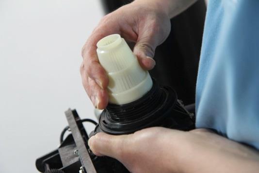
6 4. Place the supplied funnel in the tank with the distributor tube in the middle. It is recommended that a helper hold the funnel during the fill process. A face shield or eye protection should be used during the fill procedure to prevent an injury. 5. If gravel was shipped with the unit (standard tank large units), evenly divide the gravel and pour into each tank first. Evenly divide all the softening resin and pour into each tank. The tanks should be 60-80% full when the media is installed.


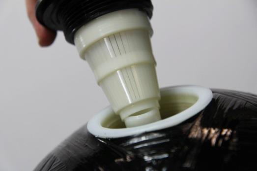
7 6. During cold weather it is recommended that the installer warm the valve to room temperature before operating. 7. Perform all plumbing according to local plumbing codes including the drain. Use a 1/2 minimum pipe/tube size for the drain. Use a 3/4 drain line for backwash flow rates that exceed 7 gpm or length that exceeds 20 (6 m). 8. Both tanks must be the same height and diameter and filled with equal amounts of media. 9. The distributor tube must be flush with the top of each tank. Cut if necessary. Remove the duct tape. Lubricate the tube and nylon seal ring on the tank. Use only non-aerosol silicone lubricant.


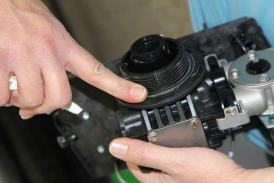
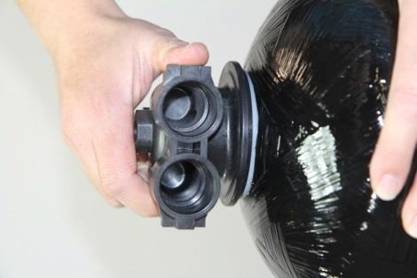
8 10. Lubricate the distributor o-ring seal and tank o-ring seal on the control valve. Install the upper basket by pushing in the slotted holes and turn it clockwise until it locks in place. Repeat these steps for the auxiliary tank adaptor.

9


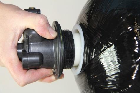
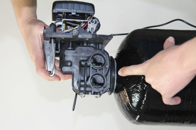
10 11. Place the main control valve on one tank and the tank adapter on the second tank. Place the valve or adaptor over the distributor tube through the bottom of the upper basket. Slide the valve or adaptor down and thread the valve on the tank by turning it clockwise. Once the valve or adaptor is hand tight turn it an additional ¼ turn to snug it to the tank.
11

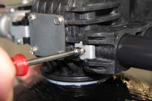
12 NOTE: If required, solder copper tubing for tank interconnection before assembling on the main control valve and tank adapter (9500 only). Maintain a minimum of 1 distance between tanks on final assembly. Plastic interconnect tubing doesn t require modification. 1 Gap Minimum 12. Connect the two tanks using the interconnect plumbing Model: Install o-rings on all four connection points on the interconnect tubing. Lubricate the o- rings and make sure they are not twisted. Slide the interconnect tubes in the valve assembly and secure them using the retaining clips. Tighten the clips once the tubes are installed. When all four clips are in place the tanks are connected. It is recommended that a minimum of 1 clearance be between the tanks to allow room for tank expansion. These tubes should be level when installation is complete. If the tubes are not even a leak could occur at the o-ring seals. If one tank is high than the other the lower tank must be shimmed to ensure the interconnect tubes are level.


13 9100 Model: Install o-rings on all four connection points on the interconnect tubing. Lubricate the o- rings and make sure they are not twisted.


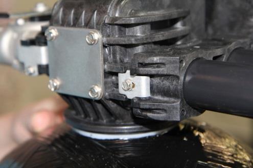
14 Slide the interconnect tubes in the valve assembly and tank adaptor. Then secure them using the retaining clips. Tighten the clips once the tubes are installed. When all four clips are in place the tanks are connected. It is recommended that a minimum of 1 clearance be between the tanks to allow room for tank expansion.
15
16


17 These tubes should be level when installation is complete. If the tubes are not level or in a bind, a leak could occur at the o-ring seals. If one tank is high than the other the lower tank must be shimmed to ensure the interconnect tubes are level. The tanks and tubes should be close to level as possible Model: Install o-rings on all four connection points on the interconnect tubing. Make sure all solder joints are completed and the tubes are cooled before installing the o-rings. Lubricate the o- rings and make sure they are not twisted. Slide the interconnect tubes in the valve assembly and tank adaptor. Then secure them using the retaining clips. Tighten the clips once the tubes are installed. When all four clips are in place the tanks are connected. It is recommended that a minimum of 1 clearance be between the tanks to allow room for tank expansion. These tubes should be level when installation is complete. If the tubes are not even a leak could occur at the o-ring seals. If one tank is high than the other the lower tank must be shimmed to ensure the interconnect tubes are level. 13. Attach the plumbing according to local codes Model: The inlet and outlet pipes will attach to the 1 female threads on bypass valve. The bypass valve will be labeled with arrows. The inlet port will have an arrow pointing toward the unit and the outlet will have an arrow pointing away from the unit. If soldering is necessary it is recommended that solder joints closer than 6 to the unit be completed prior to screwing the pipes into the bypass. Excessive heat close to the bypass valve can damage the unit.

18
.")
19 IN OUT Figure: A 9000 Model: The inlet and outlet plumbing will be connected to the 1 female connections on the unit. If there is no bypass on the unit, a three valve bypass should be plumbed in to bypass the unit if necessary (Figure: A). There are arrows stamped in the connection points that indicate the inlet and outlet connections. The arrow pointing toward the unit is the inlet and the arrow pointing away from the unit is the outlet Model: The inlet and outlet plumbing will be connected to the 1 1/2 female connections on the unit. A three valve bypass should be plumbed in to bypass the unit if necessary (Figure: A).The external meter will thread into the outlet port on the valve. There are arrows stamped in the plumbing connection points that indicate the inlet and outlet connections. The arrow pointing toward the unit is the inlet and the arrow pointing away from the unit is the outlet. 14. Solder joints near the drain must be done before connecting the Drain Line Flow Control fitting (DLFC). Leave at least 6 (152 mm) between the DLFC and solder joints when soldering pipes that are connected on the DLFC. Failure to do this could cause interior damage to DLFC.


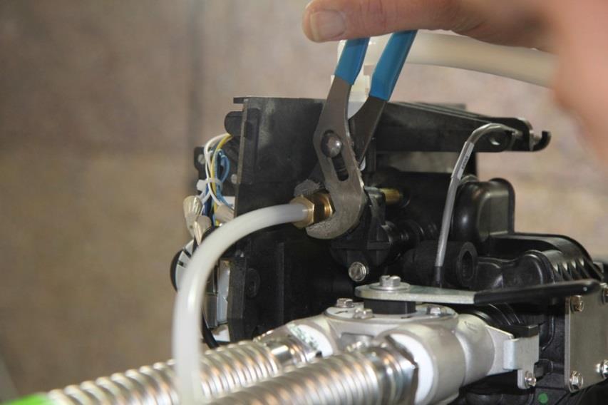
20 15. Use only Teflon tape on the drain fitting threads. Two wrenches or channel locks may be needed to tighten the barbed fitting or hard plumbing fitting if tubing is not used. Be sure not to over tighten this fitting.


21 16. Once the fittings are installed and tight, push the 5/8 drain line on the barb and secure it using a hose clamp. This tube should be attached to a sanitary drain. An air gap fitting should be installed on the drain pipe where this tube will be connected (check local codes). If this is being conveyed to a floor drain, sink or sump pump be sure to maintain a proper air gap. Typically a 1 air gap is sufficient.


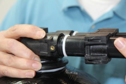
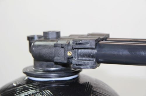
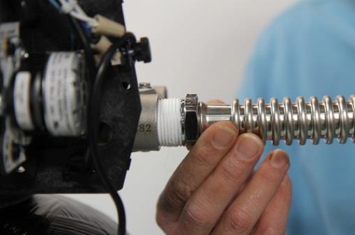
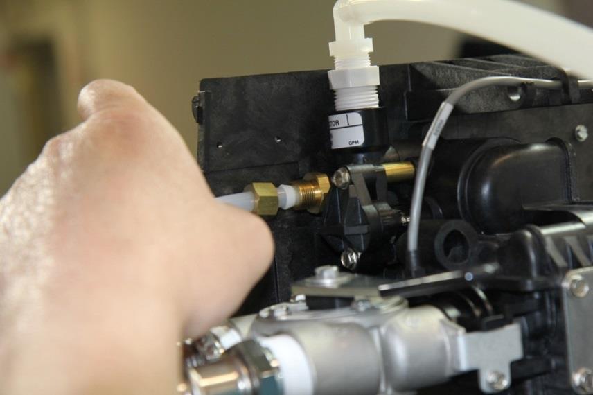
22 17. Be sure the floor under the salt storage tank is clean and level. Any debris can cause a leak when the tank is weighted down with salt and brine solution. 18. Connect the supplied 3/8 tubing to both brine connections. 19. At the control valve place the nut over the tube, install the brass sleeve in the tube. Install the cone screen in brass insert. Install the plastic flange over the tube. Install the tube in the control valve and tighten the nut by turning it clockwise. Tighten it hand tight then snug it an additional ¼ to ½ turn.

23

 in the brine")
24 20. Remove the white cap from the white tube in the brine tank. Place the other end of the tube through the hole in the side of the bine tank. Remove the nut from the brine safety valve. BE CAREFUL, not to drop the nut and sleeves (2) in the brine tube.


25 21. Place the nut over the tube. Be sure the brass insert is in the tube.


26 22. Now place the black split ring on the tube with the coned side facing the nut. 23. Now place the white ring on the tube with the shoulder touching the black split ring.


27 24. Insert the tube in the brine safety valve elbow and tighten the nut by turning it clock wise. Tighten the nut hand tight and snug it an additional ¼ to ½ turn. Place the white cap back on the white tube. 25. There is a barb fitting on the side of the brine tank. This is used as an overflow and only is used if the brine tank overfills. This barb is for 5/8 tubing. If you elect to use tubing for this elbow, run it to a floor drain or sump pump.


28 26. Place 3-6 bags of salt in the salt tank. The salt tank is full when the salt level is 1 below the white tube in the brine tank. Pour in 5 gallons of water. The salt should be used then refilled. It is not a good practice to top off the salt weekly. It is better to use it all then refill it. 27. Place the unit in the Bypass position. There is a pointer on the bypass valve handle. This pointer should be pointing to bypass on the valve. When the bypass valve is in the bypass position the handle will bisect the plumbing connections. Turn on the main water supply. Open a cold soft water tap nearby and let water run a few minutes or until the system is free of foreign material (usually solder) resulting from the installation. Close the water tap when water runs clean.

29 28. Slowly place the bypass In Service position and let water flow into the mineral tank. Open the bypass in small increments until it is fully open. When water flow stops, slowly open a cold water tap nearby and let water run until air is purged from the unit. Preferably a garden spigot or bath tube. Then close tap once the water runs clear and there is no air in the system. The bypass valve pointer should be pointing toward service and the handle should be in line with the plumbing connections. Electrical 29. Make all electrical connections according to codes. Plug the valve into an approved power source. 30. Tank one (or U1) has the control valve and tank two (or U2) has the adapter. 31. Look on the right side of the control valve, it has indicators showing which position the control valve is in during Regeneration and which tank is In Service. Control Valve Position Indicators 32. The valve position and tank in service will also be displayed on the control panel. If the unit is in the regeneration process the cycle will be shown and periodically it will flash to the tank in service. When the system is in the service position it will display the time of day and flash to the tank in service and the amount of gallons that are remaining before a regeneration of the tank in service is required.
30 TIMER FEATURES Error/ Information Icon Parameter Data PM Display Display Indicator S e r v i c e Icon Flow Indicator x1000 Indicator Extra Cycle Button Up B u t t o n D o w n B u t t o n 1. When in the service mode the service icon will be illuminated. If a delayed regeneration is initiated the service icon will blink. 2. The flow indicator icon will blink when water is being used. 3. When setting the time of day and delayed regeneration time, be sure the clock is in the correct 12 hour time cycle. When you are in the PM time cycle the PM icon will be illuminated. If it is not illuminated the clock is in the AM time cycle. 4. When the display is in the service mode it will flash from the time of day to the tank in service (U1 or U2) and then to the remaining capacity (in gallons) 5. When water is being used and the flow icon is blinking the remaining capacity value will decrease for each gallon used. 6. The service icon will be illuminated during programming or regeneration. 7. The extra cycle button serves as an enter/return button when programming. The up and down arrows allow value changes in each parameter programming mode. Once the value is reached the extra cycle button can be pushed to save the value and move to the next parameter. 8. The extra cycle button also initiates immediate or delayed regenerations. Pushing and releasing it immediately triggers a delayed regeneration (will regenerate at the time specified under RT in the programming mode). The service icon will blink when a delayed regeneration is initiated. Pushing and holding the extra cycle button for 5 seconds will initiate an immediate regeneration. The service icon will blink and the valve will move to the first regeneration position and begin the process. 9. If the error icon is illuminated there is a problem with the unit and a service technician should be
31 contacted. 10. The x1000 icon will illuminate when values are multiplied by 1000 (capacity setting). 11. The system will hold the values for up to 48 hours after a power outage. Outages exceeding 48 hours should have the programming values revisited. It is a good idea to write down the programming parameters/values so they are available if a reprogramming is required. General and Commercial Installation Checklist WATER PRESSURE: A minimum of 25 pounds of water pressure is required for regeneration valve to operate effectively. ELECTRICAL FACILITIES: A continuous 115 volt, 60 Hertz current supply is required. Make certain the current supply is always energized and cannot be turned off with another switch. EXISTING PLUMBING: Condition of existing plumbing should be free from lime and iron buildup. Piping that is built up heavily with lime and/or iron should be replaced. If piping is clogged with iron, a separate iron filter unit should be installed ahead of the water softener. LOCATION OF SOFTENER AND DRAIN: The softener should be located close to a drain. BY-PASS VALVES: Always provide for the installation of a by-pass valve. Valve to Tank Installation Instructions 1. Spin the valve onto the tank, ensuring the threads are not cross-threaded. NOTE: All Fleck valves are right-hand threads, or clockwise, to install 2. Rotate the valve freely without using force until it comes to a stop (this position is considered zero). 3. Rotate the valve clockwise from zero, between 1/4 turn and 1/2 turn (see the diagram below).
32 Programming Setting the Time of Day 1. Press and hold either the Up or Down buttons until the programming icon replaces the service icon and the parameter display reads DO. 2. Adjust the displayed time with the Up and Down buttons. 3. When the desired time is set, press the Extra Cycle button to resume normal operation. The unit will also return to normal operation after 5 seconds if no buttons are pressed. Queuing a Regeneration 1. Press the Extra Cycle button and release. The service icon will flash to indicate that regeneration is queued. 2. To cancel a queued regeneration, press the Extra Cycle button and release. Regenerating Immediately Press and hold the Extra Cycle button for five seconds. Entering Master Programming Mode Set the Time Of Day display to 12:01 P.M. Press the Extra Cycle button (to exit Setting Time of Day mode). Then press and hold the Up and Down buttons together until the programming icon replaces the service icon and the Display Format screen appears. Exiting Master Programming Mode Press the Extra Cycle button to accept the displayed settings and cycle to the next parameter. Press the Extra Cycle button at the last parameter to save all settings and return to normal operation. The control will automatically disregard any programming changes and return to normal operation if it is left in Master Programming mode for 5 minutes without any keypad input. Resets Soft Reset: Press and hold the Extra Cycle and Down buttons for 25 seconds while in normal Service mode. This resets all parameters to the system default values, except the volume remaining in meter immediate or meter delayed systems and days since regeneration in the time clock system. Master Reset: Hold the Extra Cycle button while powering up the unit. This resets all of the parameters in the unit. Check and verify the choices selected in Master Programming Mode. THE HIGHLIGHTED VALUES ARE THE SELECTIONS THAT SHOULD BE MADE. SOME PARAMETERS WILL REFER TO THE SETTINGS CHART FOR VALUES. 1. Display Format (Display Code DF) This is the first screen that appears when entering Master Programming Mode. The Display Format setting specifies the unit of measure that will be used for volume and how the control will display the Time of Day. This option setting is identified by DF in the upper left hand corner of the screen. There are three possible settings: Display Format Setting Unit of Volume Time Display GAL U.S. Gallons 12-Hour AM/PM Ltr Liters 24-Hour
33 2. Valve Type (Display Code VT) Press the Extra Cycle button. Use this display to set the Valve Type. The Valve Type setting specifies the type of cycle that the valve follows during regeneration. Note that some valve types require that the valve be built with specific subcomponents. Ensure the valve is configured properly before changing the Valve Type setting. This option setting is identified by VT in the upper left hand corner of the screen. There are 5 possible settings: Abbreviation df1b df2b Fltr UFbd Parameter Standard Downflow/Upflow, Single Backwash Standard Downflow/Upflow, Double Backwash Filter Upflow Brine First 8500 TwinFlo 100 Othr Other 3. Control Type (Display Code CT) Press the Extra Cycle button. Use this display to set the Control Type. This specifies how the control determines when to trigger regeneration. For details on how the various options function, refer to the Timer Operation section of this service manual. This option setting is identified by CT in the upper left hand corner of the screen. There are four possible settings: Meter Delayed: Meter Immediate: Time Clock: Day of Week: Fd FI tc day 4. Number of Tanks (Display Code NT) Press the Extra Cycle button. Use this display to set the Number of Tanks in your system. This option setting is identified by NT in the upper left hand corner of the screen. There are two possible settings: Single Tank System: 1 Two-Tank System: 2
34 5. Tank in Service (Display Code TS) Press the Extra Cycle button. Use this display to set whether tank one or tank two is in service. This option setting is identified by TS in the upper left hand corner of the screen. This parameter is only available if the number of tanks has been set to 2. There are two possible settings: Tank One in Service: U1 Tank Two in Service: U2 NO CHANGES NECESSARY ON THIS PARAMATER 6. Unit Capacity (Display Code C) Press the Extra Cycle button. Use this display to set the Unit Capacity. This setting specifies the treatment capacity of the system media. Enter the capacity of the media bed in grains of hardness when configuring a softener system, and in the desired volume capacity when configuring a filter system. This option setting is identified by C in the upper left hand corner of the screen. The Unit Capacity parameter is only available if the control type has been set to one of the metered options. Use the Up and Down buttons to adjust the value as needed. Range: 1-999,900 gallons (100-9,999,000 Liters) Use the following chart to determine your capacity setting. System Size 26,000 Grain 35,000 Grain 53,000 Grain 70,000 Grain 88,000 Grain 105,000 Grain 140,000 Grain Low Salt Settings Medium Salt Settings High Salt Settings Capacity Brine Fill Capacity Setting Brine Fill Capacity Brine Fill Setting (mins.) (mins.) Setting (mins.) 15, , , , , , , , , , , , , , , , , , , , ,000 40
35 7. Feed Water Hardness (Display Code H) Press the Extra Cycle button. Use this display to set the feed water hardness. Enter the feed water hardness in grains per unit volume for softener systems, or 1 for filter systems. This option setting is identified by H in the upper left hand corner of the screen. The feed water hardness parameter is only available if the control type has been set to one of the metered options. Use the Up and Down buttons to adjust the value as needed. Range: hardness The hardness level should be set 5 GPG above the actual water feed hardness. The hardness level from the original feed water test will either be expressed in GPG (grains per gallon) or ppm/mg/l (parts per million/milligrams per liter). If the reading is in ppm/mg/l, then divide that value by 17.1 to get GPG. This system only allows hardness inputs in GPG. 8. Reserve Selection (Display Code RS) Press the Extra Cycle button. Use this display to set the Safety Factor. Use this display to select the type of reserve to be used in your system. This setting is identified by RS in the upper left-hand corner of the screen. The reserve selection parameter is only available if the control type has been set to one of the metered options. There are two possible settings. SF RC Safety Factor Fixed Reserve Capacity 9. Safety Factor (Display Code SF) Press the Extra Cycle button. Use this display to set the Safety Factor. This setting specifies what percentage of the system capacity will be held as a reserve. Since this value is expressed as a percentage, any change to the unit capacity or feed water hardness that changes the calculated system capacity will result in a corresponding change to the reserve volume. This option setting is identified by SF in the upper left hand corner of the screen. Use the Up and Down buttons to adjust the value from 0 to 50% as needed. SET THIS TO 0. THERE IS NO NEED FOR A SAFETY FACTOR WITH A TWIN ALTERNATING UNIT. Range: 0-50%
36 10. Fixed Reserve Capacity (Display Code RC) Press the Extra Cycle button. Use this display to set the Reserve Capacity. This setting specifies a fixed volume that will be held as a reserve. The reserve capacity cannot be set to a value greater than one-half of the calculated system capacity. The reserve capacity is a fixed volume and does not change if the unit capacity or feed water hardness is changed. This option setting is identified by RC in the upper left-hand corner of the screen. Use the Up and Down buttons to adjust the value as needed. Range: 0-half the calculated capacity WILL NOT BE DISPLAYED WHEN USING SF (SAFETY FACTOR) 11. Day Override (Display Code DO) Press the Extra Cycle button. Use this display to set the Day Override. This setting specifies the maximum number of days between regeneration cycles. If the system is set to a timer-type control, the day override setting determines how often the system will regenerate. A metered system will regenerate regardless of usage if the days since last regeneration cycle equal the day override setting. Setting the day override value to OFF disables this function. This option setting is identified by DO in the upper left hand corner of the screen. Use the Up and Down buttons to adjust the value as needed. Range: Off-99 days This will most likely be set at 14 days unless you take vacations lasting more than two weeks. Most households will eclipse the gallon capacity prior to the override engaging. However, if you are gone for two weeks it is a good idea to set this at 10 days so it regenerates and is fresh when you return. Water standing in the system for longer than 14 days can become stagnant. 12. Regeneration Time Press the Extra Cycle button. Use this display to set the Regeneration Time. This setting specifies the time of day the control will initiate a delayed, manually queued, or day override triggered regeneration. This option setting is identified by RT in the upper left hand corner of the screen. Use the Up and Down buttons to adjust the value as needed. This feature is only used when a delayed regeneration is initiated.
37 13. Regeneration Cycle Step Times Press the Extra Cycle button. Use this display to set the Regeneration Cycle Step Times. The different regeneration cycles are listed in sequence based on the valve type selected for the system, and are identified by an abbreviation in the upper left-hand corner of the screen. The abbreviations used are listed below. If the system has been configured with the OTHER valve type, the regeneration cycles will be identified as R1, R2, R3, R4, R5, and R6. Each cycle step time can be set from 0 to 199 minutes. Setting a cycle step time to 0 will cause the control to skip that step during regeneration, but keeps the following steps available. Use the Up and Down buttons to adjust the value as needed. Press the Extra Cycle button to accept the current setting and move to the next parameter. Abbreviation BW BD RR BF Cycle Step Backwash 10 Mins Brine Draw 60 Mins Rapid Rinse 10 Mins. Brine Fill (see chart) Range: minutes This setting is determined by the chart used for the capacity setting. Input the number of minutes that corresponds to the capacity setting that was chose previously. System Size 26,000 Grain 35,000 Grain 53,000 Grain 70,000 Grain 88,000 Grain 105,000 Grain 140,000 Grain Low Salt Settings Medium Salt Settings High Salt Settings Capacity Brine Fill Capacity Setting Brine Fill Capacity Brine Fill Setting (mins.) (mins.) Setting (mins.) 15, , , , , , , , , , , , , , , , , , , , ,000 40
38 14. Flow Meter Type (Display Code FM) Press the Extra Cycle button. Use this display to set the type of flow meter connected to the control. This option setting is identified by FM in the upper left-hand corner of the screen. Use the Up and Down buttons to select one of the 7 available settings. t0.7 Fleck 3/4 Turbine Meter P0.7 Fleck 3/4 Paddle Wheel Meter t1.0 Fleck 1 Turbine Meter P1.0 Fleck 1 Paddle Wheel Meter t1.5 Fleck 1 1/2 Turbine Meter P1.5 Fleck 1 1/2 Paddle Wheel Meter P2.0 Fleck 2 Paddle Wheel Meter GEn Generic/Other Meter THE 9500 VALVE WILL USE t1.5 FOR THIS SETTING. 15. End of Master Programming Mode Press the Extra Cycle button to save all settings and exit Master Programming Mode USER PROGRAMMING MODE User Programming Mode Options Abbreviation Parameter Description DO Day Override The timer s day override setting RT H Regeneration Time Feed Water Hardness The time of day that the system will regenerate (meter delayed, timeclock, and day-of-week systems) The hardness of the inlet water - used to calculate system capacity for metered systems RC or SF Reserve Capacity The fixed reserve capacity CD Current Day The current day of week NOTE: Some items may not be shown depending on timer configuration. The timer will discard any changes and exit User Mode if any button is not pressed for sixty seconds. User Programming Mode Steps 1. Press the Up and Down buttons for five seconds while in service, and the time of day is NOT set to 12:01 PM. 2. Use this display to adjust the Day Override. This option setting is identified by DO in the upper left hand corner of the screen.
39 3. Press the Extra Cycle button. Use this display to adjust the Regeneration Time. This option setting is identified by RT in the upper left hand corner of the screen. 4. Press the Extra Cycle button. Use this display to adjust the Feed Water Hardness. This option setting is identified by H in the upper left hand corner of the screen. Range: hardness 5. Press the Extra Cycle button. Use this display to adjust the Fixed Reserve Capacity. This option setting is identified by RC or "SF" in the upper left-hand Corner of the screen. 6. Press the Extra Cycle button. Use this display to set the Current Day of the Week. This option setting is identified by CD in the upper left hand corner of the screen. 7. Press the Extra Cycle button to end User Programming Mode.
40 DIAGNOSTIC PROGRAMMING MODE Diagnostic Programming Mode Options Abbreviation Parameter Description FR Flow Rate Displays the current outlet flow rate PF HR Peak Flow Rate Hours in Service Displays the highest flow rate measured since the last regeneration Displays the total hours that the unit has been in service VU Volume Used Displays the total volume of water treated by the unit RC SV Reserve Capacity Software Version Displays the system s reserve capacity calculated from the system capacity, feedwater hardness, and safety factor Displays the software version installed on the controller NOTE: Some items may not be shown depending on timer configuration. The timer will exit Diagnostic Mode after 60 seconds if no buttons are pressed. Press the Extra Cycle button to exit Diagnostic Mode at any time. Diagnostic Programming Mode Steps 1. Press the Up and Extra Cycle buttons for five seconds while in service. 2. Use this display to view the current Flow Rate. This option setting is identified by FR in the upper left hand corner of the screen. 3. Press the Up button. Use this display to view the Peak Flow Rate since the last regeneration cycle. This option setting is identified by PF in the upper left hand corner of the screen. 4. Press the Up button. Use this display to view the Hours in Service since the last regeneration cycle. This option setting is identified by HR in the upper left hand corner of the screen. 5. Press the Up button. Use this display to view the Volume Used since the last regeneration cycle. This option setting is identified by VU in the upper left hand corner of the screen. 6. Press the Up button. Use this display to view the Reserve Capacity. This option setting is identified by RC in the upper left hand corner of the screen.
41 7. Press the Up button. Use this display to view the Software Version. This option setting is identified by SV in the upper left hand corner of the screen. Press the Extra Cycle button to end Diagnostic Programming Mode.
42 Troubleshooting Problem Cause Correction 1. Water conditioner fails to A. Electrical service to unit A. Assure permanent electrical service regenerate. has been interrupted (check fuse, plug, pull chain, or switch) B. Control is defective. B. Replace Control. C. Power failure. C. Reset time of day. 2. Hard water. A. By-pass valve is open. A. Close by-pass valve. B. No salt is in brine tank. B. Add salt to brine tank and maintain salt level above water level. C. Injector screen plugged. C. Clean injector screen. D. Insufficient water flowing into brine tank. D. Check brine tank fill time and clean brine line flow control if plugged. E. Hot water tank hardness. E. Repeated flushings of the hot water tank is required. F. Leak at distributor tube. F. Make sure distributor tube is not cracked. Check O-ring and tube pilot. G. Internal valve leak. G. Replace seals and spacers and/or piston. 3. Unit used too much salt. A. Improper salt setting. A. Check salt usage and salt setting. B. Excessive water in brine tank. B. See problem Loss of water pressure. A. Iron buildup in line to water A. Clean line to water conditioner. conditioner. 5. Loss of mineral through drain line. B. Iron buildup in water conditioner. B. Clean control and add mineral cleaner to mineral bed. Increase frequency of regeneration. C. Inlet of control plugged due C. Remove piston and clean control. to foreign material broken loose from pipes by recent work done on plumbing system. A. Air in water system. A. Assure that well system has proper air eliminator control. Check for dry well condition. B. Improperly sized drain line B. Check for proper drain rate. flow control. 6. Iron in conditioned water. A. Fouled mineral bed. A. Check backwash, brine draw, and brine tank fill. Increase frequency of regeneration. Increase backwash time. 7. Excessive water in brine tank. A. Plugged drain line flow control. A. Clean flow control. B. Plugged injector system. B. Clean injector and screen. C. Timer not cycling. C. Replace timer. D. Foreign material in brine valve. D. Replace brine valve seat and clean valve. E. Foreign material in brine line flow control. E. Clean brine line flow control.
43 Troubleshooting Problem Cause Correction 8. Softener fails to draw brine. A. Drain line flow control A. Clean drain line flow control. is plugged. B. Injector is plugged. B. Clean injector 9. Control cycles continuously. A. Misadjusted, broken, or shorted switch. C. Injector screen plugged. C. Clean screen. D. Line pressure is too low. D. Increase line pressure to 20 P.S.I. E. Internal control leak E. Change seals, spacers, and piston assembly. F. Service adapter did not cycle. F. Check drive motor and switches. 10. Drain flows continuously. A. Valve is not programming correctly. A. Determine if switch or timer is faulty and replace it, or replace complete power head. A. Check control program and positioning of control. Replace power head assembly if not positioning properly. B. Foreign material in control. B. Remove power head assembly and inspect bore. Remove foreign material and check control in various regeneration positions. C. Internal control leak. C. Replace seals and piston assembly.
44 9000 Control Dimensions
45 9100 Control Dimensions
46 9500 Control Dimensions
47 Water Conditioner Flow Diagrams In Service Position Tanks Switching Position (Meter Initiated Regeneration) Backwash Position Brine Draw Position
48 Water Conditioner Flow Diagrams Slow Rinse Position Rapid Rinse Position Brine Tank Fill Position In Service Position, Tanks Switched
49 9000/9500 Wiring Diagram 19752_REVB
50 NOTES
Installation and Instructions 2. Product Features 3-6. Key Pad Functions 7. Distributor Information Programming Guide 8. Master Programming Guide 9-14
 Installation and Instructions 2 Product Features 3-6 Key Pad Functions 7 Distributor Information Programming Guide 8 Master Programming Guide 9-14 Dimensional Drawing 15 D-STC & D-SMM Valve Assembly 16-17
INSTALLATION & START-UP INSTRUCTIONS FLECK 9100SXT METER TWIN ALTERNATING WATER SOFTENER SYSTEMS
 INSTALLATION & START-UP INSTRUCTIONS FLECK 9100SXT METER TWIN ALTERNATING WATER SOFTENER SYSTEMS 1999-2007 QualityWaterForLess.com - 1 - info@qualitywaterforless.com Preface: Thank you for your purchase
Owners Manual Models: 075-AQF-CX. Aquatrol Backwashing Catalytic Carbon Filter. Visit us online at.
 Visit us online at www.uswatersystems.com Aquatrol Backwashing Catalytic Carbon Filter Owners Manual Models: 075-AQF-CX REVISION # 1.0 REVISION DATE October 11, 2017 US Water Systems, Inc. 1209 Country
DRS4-RM Manual. Set Up Instructions for DRS4 Series Single Tank
 Set Up Instructions for DRS4 Series Single Tank Inspect the packaging of the equipment to confirm that nothing was damaged during shipping. (Figure 1) Remove the resin tank(s) and valve(s) from the packaging.
INSTALLATION & START-UP INSTRUCTIONS. Clack WS1 & WS1.25 METER WATER SOFTENER SYSTEMS
 INSTALLATION & START-UP INSTRUCTIONS Clack WS1 & WS1.25 METER WATER SOFTENER SYSTEMS 1999-2009 QualityWaterForLess.com - 1 - info@qualitywaterforless.com Preface: Thank you for your purchase of a new Water
Commercial Softeners. Installation, Operation & Maintenance Guide. Manual 002.1
 Commercial Softeners Installation, Operation & Maintenance Guide Manual 002.1 Contents Page 1. Unpacking Instructions 3 2. Installation 3 Pre-installation checks Fitting the bottom distribution system
E L E C T R O N I C S X T
 1 - VAV OPRATO Regeneration button. ervice indicator: - Valve in service: lighted icon - ight regeneration: flashing icon nformation indicator, viewed in Diagnostic & rror modes ndicator in programmation
Duplex Commercial Softeners
 Duplex Commercial Softeners Installation, Operation & Maintenance Guide Manual 003.1 Contents Page 1. Unpacking Instructions 3 2. Installation 4 Pre-installation checks Fitting the bottom distribution
NORMAL OPERATING DISPLAYS GENERAL OPERATION
 SunTapWat e rsys t e ms WS1Cl ac kwat e rsof t ne r Owne r smanual MAIN COMPONENTS Your water treatment system is a point of entry (POE) system composed of three components: A. The control valve and computer
The ultimate in water softening
 Calming troubled waters Metered Water Softener Specification MODEL: CALSOFT M The ultimate in water softening Due to Calmag s commitment to new product development the photographs contained within these
265 Series Valve Operation Manual
 265 Series Valve Operation Manual Note: 1. Read all instructions carefully before operation. 2. Avoid pinched o-rings during installation by applying (provided with install kit) NSF certified lubricant
Easy Nest Kits. Installation Suggestions
 Easy Nest Kits Installation Suggestions 2 General Recommendations Hydraulics Vacuum breakers should be installed to prevent siphoning. Flexible connectors should follow FRP tank manufacturers recommendations.
Performa Cv Twin Alternating and High Flow Systems. Manual Supplement
 Performa Cv Twin Alternating and High Flow Systems Manual Supplement Table of Contents 1.0 Installation and Start-Up.............. 3 Water Line Connection Brine Tank Turbine Connection Connecting Manifold
Chloramines Removal Filter CLF20 and CLF35 Models
 Chloramines Removal Filter CLF20 and CLF35 Models Operating and Maintenance Manual #51793 Rev. 6/09 Performance and Specifications Recommended Mineral Installation Shipping Item Model Media Flow Rate Tank
Autotrol Performa ProSoft
 Autotrol Performa ProSoft With 960 Series Control 5-Cycle Conditioner 5-Cycle FA Filter Water Conditioning Control System Installation, Operation and Maintenance Manual Table of Contents Installation.....................................
AQUAMATIC EASY NEST KITS INSTALLATION SUGGESTIONS
 AQUAMATIC EASY NEST KITS INSTALLATION SUGGESTIONS TABLE OF CONTENTS TABLE OF CONTENTS...2 GENERAL RECOMMENDATIONS...2 TROUBLESHOOTING GUIDE...3 EXISTING EASY NEST SYSTEM TROUBLESHOOTING GUIDE...4 COMPONENT
Iron Filter Installation / Operation Manual
 Iron Filter Installation / Operation Manual BrassMaster and BrassMaster Plus Technical Video Library: http://watercontrolinc.com/residential-technical-support/residential-technical-videos BrassMaster technical
Operation Manual. Carbon Filtration Industrial Drive, Orlinda, TN fax
 Operation Manual Carbon Filtration 615-654-4441 sales@specialtyh2o.com 615-654-4449 fax TABLE OF CONTENTS Section 1 GENERAL 1.1 Warnings and Cautions... 1 1.2 Theory of Operation... 2 1.3 System Illustration...
O&M Receiving and Inspection. Storage of Water Treatment Media
 O&M 105.1 Receiving and Inspection 1. Equipment should be checked against the Bill of Lading to verify that the number of pieces received matches those shipped. 2. Equipment should be carefully inspected
Autotrol Performa Filter Valve Series
 TM Autotrol Performa Filter Valve Series 440i Control 940F Control 960F Control Water Conditioning Control System Installation, Operation and Maintenance Manual Table of Contents Installation............................
Softeners Clack Model V125DTH Medical / Industrial Series Operation and Service Manual
 Softeners Clack Model V125DTH Medical / Industrial Series Operation and Service Manual www.ameriwater.com 800-535-5585 AmeriWater LLC 3345 Stop 8 Rd. Dayton, OH 45414 Clack Softener Manual, 98-0180 Rev.
CAN 565 Series. Softener Manual
 CAN 565 Series Softener Manual Note: 1. Read all instructions carefully before operation. 2. Avoid pinched o-rings during installation by applying (provided with install kit) NSF certified lubricant to
Softener / Filter Fleck Model 2850 SXT Medical / Industrial Series Operation and Service Manual
 Softener / Filter Fleck Model 2850 SXT Medical / Industrial Series Operation and Service Manual www.ameriwater.com 800-535-5585 AmeriWater 3345 Stop 8 Rd. Dayton, OH 45414 98-0107 Rev. I 2018-02-09 Table
Tech Manual Powerline Softener (PS) Series
 Series") Tech Manual Powerline Softener (PS) Series Models: PS 2161 PS 2465 PS 2472 PS 3072 PS 3657 PS 3672 PS 4272 PS 4872 Page - 1 TABLE OF CONTENTS General Information About this Manual...3 The Powerline Product
Tech Manual Powerline Softener (PS) Series Models: PS 2161 PS 2465 PS 2472 PS 3072 PS 3657 PS 3672 PS 4272 PS 4872 Page - 1 TABLE OF CONTENTS General Information About this Manual...3 The Powerline Product
OWNER S MANUAL & INSTALLATION GUIDE
 OWNER S MANUAL & INSTALLATION GUIDE MicroTurb Premium Series Turbidity Filters w/ NextSand highly effective and economical sediment / turbidity / particulate reduction filters with higher flow rates, lower
ACTIVATE YOUR WARRANTY BY REGISTERING YOUR PRODUCT AT
 OWNER'S MANUAL MAX Specialty Series with Triton Metered and Timered Electronic Control Valves ACTIVATE YOUR WARRANTY BY REGISTERING YOUR PRODUCT AT www.watertech.com or call 888-254-8412 Dealer Contact
I came that they may have life and have it abundantly. John 10:10 Providing the quality water you deserve at a price you can afford!
 1 of 20 I came that they may have life and have it abundantly. John 10:10 Providing the quality water you deserve at a price you can afford! Installation Instructions for All- in- One Systems with Fleck
IWT 565 Series HTO Series Operation Manual
 IWT 565 Series HTO Series Operation Manual Note: 1. Read all instructions carefully before operation. 2. Avoid pinched o-rings during installation by applying (provided with install kit) NSF certified
SOFTENER D-DF & D-UF Series
 Water conditioning System. SOFTENER D-DF & D-UF Series INSTRUCTION MANUAL, OPERATION & MAINTENANCE 1. - PRESENTATION. In this manual, what is described are the required actions for the instalment, start
Owner s Manual. R&M Water Group TM. Models: SA-TECH PLUS 40 DB SA-TECH PLUS 48 DB
 TM Owner s Manual Models: SA-TECH PLUS 40 DB SA-TECH PLUS 48 DB R&M Water Group TM Water Conditioning & Purification Systems A Division of Water Technologies, Inc. 28 South 1550 West, Lindon, Utah 84042
Owners Manual 081-MXF-PH-XXX. US Water Systems Matrixx ph Balancing Backwashing Filter. Visit us online at
 Visit us online at www.uswatersystems.com US Water Systems Matrixx ph Balancing Backwashing Filter Owners Manual 081-MXF-PH-XXX REVISION # 1.1 REVISION DATE December 4, 2018 US Water Systems Corporate
Installation of Your SprayMaster System
 Installation of Your SprayMaster System 1. At the installation site, remove all equipment from the corrugated box and the polyethylene drum and replace the drum lid. Check the picture to identify each
Series 180. Commercial/Industrial Control System Installation, Operation and Maintenance Manual
 Series 180 Commercial/Industrial Control System Installation, Operation and Maintenance Manual Table of Contents Installation............................ 3 Plumbing Inlet and Outlet Piping Drain Line Piping
With 960 Series Control Water Conditioning Control System Installation, Operation and Maintenance Manual
 With 960 Series Control Water Conditioning Control System Installation, Operation and Maintenance Manual Part# AP-5100 AP-5125 AP-5150 Manufactured by: Good Water Warehouse Inc. 1700 E. Walnut Ave Fullerton,
SpectraPure PUMPED RO SYSTEMS (PSP) User s Manual for PSP-1500 Systems
 User s Manual for PSP-1500 Systems") SpectraPure PUMPED RO SYSTEMS (PSP) User s Manual for PSP-1500 Systems 2 3 PSP-1500 SYSTEM DESCRIPTION Reverse Osmosis RO Reverse Osmosis utilizes the unique properties of a semi-permeable membrane to
SpectraPure PUMPED RO SYSTEMS (PSP) User s Manual for PSP-1500 Systems 2 3 PSP-1500 SYSTEM DESCRIPTION Reverse Osmosis RO Reverse Osmosis utilizes the unique properties of a semi-permeable membrane to
Installation, Operation and Maintenance Manual
 Installation, Operation and Maintenance Manual Model H2F H2Flow Anti-Scale System Chemical-Free, Salt-Free Scale Prevention Introduction The H2Flow Anti-Scale System will condition the tap water providing
COMMERCIAL WATER SOFTENERS / FILTERS
 MANUAL to Install, Program, Operate and Maintain COMMERCIAL WATER SOFTENERS / FILTERS with 1 Single Disc Valve If you have questions when installing, programming, operating or maintaining this system CALL
AIR COMPRESSOR. Failure to follow all instructions as listed below may result in electrical shock, fire, and/or serious personal injury.
 2 GALLON AIR COMPRESSOR Model: 7517 DO NOT RETURN TO STORE. Please CALL 800-348-5004 for parts and service. CALIFORNIA PROPOSITION 65 WARNING: You can create dust when you cut, sand, drill or grind materials
2300 Duplex Softener Manual
 2300 Duplex Softener Manual Installation / Operation Manual 1 Softener Specifications... Page 3 Softener Installation... Page 5 Service Information... Page 8 Shuttle Powerhead... Page 12 Shuttle Valve...
Jacuzzi. J-CQ420 Cartridge Filter Installation and Operating Instructions
 Jacuzzi J-CQ420 Cartridge Filter Installation and Operating Instructions IMPORTANT SAFETY PRECAUTIONS ATTENTION INSTALLER: This guide contains important information about the installation, operation and
Installation and Use Manual
 Installation and Use Manual EMASMB & LMASMB Surface Mount Bottle Filling Stations Model EMASMB IMPORTANT THIS IS AN INDOOR APPLICATION ONLY! ALL SERVICE TO BE PERFORMED BY AN AUTHORIZED SERVICE PERSONNEL.
Installation, Operation and Maintenance Instructions for Electronically Controlled Pressurisation Units
 Installation, Operation and Maintenance Instructions for Electronically Controlled Pressurisation Units Models: EPS Single Pump EPT Twin Pump EPS-HP EPT-HP Single Pump High Pressure Twin Pump High Pressure
Pure Water Power Purification System 4-Stage RODI Operations Manual
 Pure Water Power Purification System 4-Stage RODI Operations Manual Flush Valve Lever Quick Disconnect for RO Water Testing Water Supply In Drain Hose Pure Water Out to Waterfed Pole New Machine Setup
Hydraulic Punch Drivers
 SERVICE MANUAL 7804SB / 7806SB Quick Draw 7704SB / 7706SB Quick Draw Flex Quick Draw Hydraulic Punch Drivers Serial Codes AHJ and YZ Read and understand all of the instructions and safety information in
MANUAL BE SERIES Test Benches
 The CustomCrimp Manual BE Series Test Benches are designed with features that make proof and burst testing of hydraulic hose assemblies a quick and easy procedure. CUSTOMIZED AND SPECIAL DESIGN BENCHES
User's Manual. MixRite TF 10. Edition 05.08
 User's Manual MixRite TF 10 Edition 05.08 1 Tefen MixRite TF 10 fertilizer and chemicals Injector Congratulations on your purchase of one of Tefen s high quality products. To get the best results from
k valve 2 (50)HF 2½ (65)SF installation guide aylesbury For valve sizes (DN): tel fax
HF 2½ (65)SF installation guide aylesbury For valve sizes (DN): tel fax") aylesbury k valve installation guide For valve sizes (DN): 2 (50)HF 2½ (65)SF 3 (80)RB IMPORTANT Please keep for future reference. PLEASE READ THESE INSTRUCTIONS CAREFULLY AND REFER TO ANY DIAGRAMS BEFORE
aylesbury k valve installation guide For valve sizes (DN): 2 (50)HF 2½ (65)SF 3 (80)RB IMPORTANT Please keep for future reference. PLEASE READ THESE INSTRUCTIONS CAREFULLY AND REFER TO ANY DIAGRAMS BEFORE
INSTRUCTION MANUAL. Automatic Water Softener System. Model: PSE-08. Xsential Water Filtration Systems
 INSTRUCTION MANUAL Automatic Water Softener System Model: PSE-08 Xsential Water Filtration Systems 78 Daly Street Ascot Western Australia 6104 Ph: 1300 366 295 Fax: (08) 9277 2266 www.xsential.com.au Welcome
Magnum Cv Series. Installation and Service Manual
 Magnum Cv Series Installation and Service Manual Table of Contents Section 1.0 Installation Profile Summary - - - - - - - - - - - - - - - - - - - - - - - -1 2.0 Introduction to the Magnum Cv Series -
Instructions for Assembly, Installation, and Operation of the Gas Addition Kit Accessory with the CEM Discover Systems
 Corporation Issued: 5/09 P/N: 600104 Rev. 2 Instructions for Assembly, Installation, and Operation of the Gas Addition Kit Accessory with the CEM Discover Systems The Gas Addition Accessory permits the
INDUSTRIAL VALVES MODELS: C62-A; C62-D. INSTRUCTION MANUAL Installation Operation Parts Service DIAPHRAGM BYPASS PRESSURE REGULATING VALVES
 INSTRUCTION MANUAL Installation Operation Parts Service IMPORTANT Record your Regulator model number and serial number here for easy reference: Model No. Serial No. Date of Purchase When ordering parts
PROPORTIONING VALVE. Model 150 INSTRUCTION MANUAL. March 2017 IMS Company Stafford Road
 PROPORTIONING VALVE Model 150 INSTRUCTION MANUAL March 2017 IMS Company 10373 Stafford Road Telephone: (440) 543-1615 Fax: (440) 543-1069 Email: sales@imscompany.com 1 Introduction IMS Company reserves
200 PSI COMPRESSORS - MODEL NUMBERS
 200 PSI COMPRESSORS - MODEL NUMBERS 380C AIR COMPRESSOR KIT PART NO. 38033 480C AIR COMPRESSOR KIT PART NO. 48043 380C 480C IMPORTANT: It is essential that you and any other operator of this product read
INSTALLATION, CARE & USE MANUAL. EMASMB & LMASMB Surface Mount Bottle Filling Stations
 INSTALLATION, CARE & USE MANUAL EMASMB & LMASMB Surface Mount Bottle Filling Stations IMPORTANT THIS IS AN INDOOR APPLICATION ONLY! ALL SERVICE TO BE PERFORMED BY AN AUTHORIZED SERVICE PERSONNEL. TOOLS/ITEMS
MUELLER. Mega-Lite Drilling Machine. Reliable Connections. table of contents PAGE. Equipment 2. Operating Instructions 3-4. Parts Information 5
 operating Instructions manual MUELLER Mega-Lite Drilling Machine table of contents PAGE Equipment 2 Operating Instructions 3-4 Parts Information 5 Travel Charts 6-11! WARNING: 1. Read and follow instructions
Booster Pump PB4-60 Replacement Kits
 Booster Pump PB4-60 Replacement Kits FOR YOUR SAFETY - This product must be installed and serviced by a contractor who is licensed and qualified in pool equipment by the jurisdiction in which the product
100C Air Compressor Kit
 10010 100C Air Compressor (standard mounting bracket, CE Spec) 10014 100C Air Compressor (no leader hose or check valve, CE Spec) 10016 100C Air Compressor (with Omega Bracket, CE Spec) IMPORTANT: It is
Vessel Installation and Operating Manual
 For In-ground and Aboveground Pools Vessel Installation and Operating Manual Important Safety Information Please read this manual prior to installation. Nature 2 Express is designed to sanitize in-ground
Assembling & Installing your Pool Cleaner
 Assembling & Installing your Pool Cleaner STEP 1: Check Contents of the Box Remove the Badu Clean Supreme body and all parts from the box and check that the following components are included. Refer to
420C AIR COMPRESSOR KIT PART NO C AIR COMPRESSOR KIT PART NO
 420C AIR COMPRESSOR KIT PART NO. 42042 460C AIR COMPRESSOR KIT PART NO. 46043 420C 460C IMPORTANT: It is essential that you and any other operator of this product read and understand the contents of this
ELECTRONIC PLC SERIES Test Benches
 Whether you are producing a single assembly or a production run, CustomCrimp has the test equipment to give both you and your customer the assurance that the product has been assembled correctly. A programmable
Logix 764 Operation Manual. Models: 255 Twin Alternating Twin Parallel Single with Remote Regeneration Start Multi-Single Tank with Lockout
 Logix 764 Operation Manual Models: 255 Twin Alternating Twin Parallel Single with Remote Regeneration Start Multi-Single Tank with Lockout 2 Table of Contents Safety Information 4 How To Use This Manual
FlashGARD HP Reverse Osmosis Filtration System Model Number FSTMO75 Part Number
 3M Water Filtration Products FlashGARD HP Reverse Osmosis Filtration System Model Number FSTMO75 Part Number 56123-06 Installer: Please leave this manual with owner/operator. End User: Please retain for
Operation and Maintenance Manual for
 Operation and Maintenance Manual for KFZST KF Series Twin Softener Systems Catalog # Serial # USFilter 10 Technology Drive Lowell, Massachusetts 01851 Tel: (800) 875-7873 Fax: (978) 441-6025 Email: Lowell_TechSupport@USFilter.com
36E DSI, HSI & Proven Pilot Two-Stage Combination Gas Valve INSTALLATION INSTRUCTIONS
 INLET PRESS TAP WTE-RODGERS 36E96-314 DSI, HSI & Proven Pilot Two-Stage Combination Gas Valve INSTALLATION INSTRUCTIONS Operator: Save these instructions for future use! FAILURE TO READ AND FOLLOW ALL
400C & 450C DUAL PERFORMANCE VALUE PACKS
 (Chrome) PART NO. 40013 (Silver) PART NO. 45012 (Chrome) PART NO. 45013 IMPORTANT: It is essential that you and any other operator of this product read and understand the contents of this manual before
200 PSI HIGH-FLOW AIR SOURCE KIT
 200 PSI HIGH-FLOW AIR SOURCE KIT 50% Duty Compressor on 2.0 Gallon Air Tank PART NO. 20008 IMPORTANT: It is essential that you and any other operator of this product read and understand the contents of
AIR COMPRESSOR OPERATING INSTRUCTION AND PARTS LIST
 AIR COMPRESSOR OPERATING INSTRUCTION AND PARTS LIST OIL-LESS TYPE IMPORTANT: PLEASE READ CAREFULLY BEFORE STARTING OPERATIONS. THE CONTENTS ARE FOR GENERAL INFORMATION OF ALL THE SIMILAR MODELS. Record
Torque Specifications
 SENR3130-10 Torque Specifications All Caterpillar Products S/N From the library of Barrington Diesel Club CONTENT General Information 01/07/2005 Introduction to Torque 01/07/2005 Torque-Turn 01/07/2005
RS(H)10,15 USER MANUAL. Read the complete manual before installing and using the regulator.
10,15 USER MANUAL. Read the complete manual before installing and using the regulator.") RS(H)10,15 USER MANUAL Read the complete manual before installing and using the regulator. WARNING INCORRECT OR IMPROPER USE OF THIS PRODUCT CAN CAUSE SERIOUS PERSONAL INJURY AND PROPERTY DAMAGE. Due to
RS(H)10,15 USER MANUAL Read the complete manual before installing and using the regulator. WARNING INCORRECT OR IMPROPER USE OF THIS PRODUCT CAN CAUSE SERIOUS PERSONAL INJURY AND PROPERTY DAMAGE. Due to
Adjustable. Unloader Valve. O&M Manual. Part #
 Adjustable Unloader Valve O&M Manual Unloader Valve Part #60-020-361 ADVANCED PRESSURE SYSTEMS 701 S. Persimmon St., Suite 85 - Tomball, TX 77375 Toll Free in North America: (877) 290-4277 Phone: (281)
REVERSE OSMOSIS WATER FILTRATION SYSTEM MODEL EWR 4075 INSTRUCTION MANUAL
 REVERSE OSMOSIS WATER FILTRATION SYSTEM MODEL EWR 4075 INSTRUCTION MANUAL Excalibur Water Systems 142 Commerce Park Drive, Unit M & N Barrie, Ontario L4N 8W8 CANADA www.excaliburwater.com 2013.05.7446
1020 Industrial Drive, Orlinda, TN fax
 Operation Manual Ultrafiltration for High Purity Distribution K-A-HPTUF Series 615-654-4441 sales@specialtyh2o.com 615-654-4449 fax TABLE OF CONTENTS Section 1 GENERAL 1.1 Warnings and Cautions... 1 1.2
icon i150 / i350 Installation / Operation Manual
 i150 Concentrator i350 Concentrator icon i150 / i350 Installation / Operation Manual www.iconcentrator.com What You Will Need to Install Your icon In order to install your icon you will have to consider
IMPORTANT SAFETY INSTRUCTIONS
 IMPORTANT SAFETY INSTRUCTIONS CAUTION - To reduce risk of electrical shock: - Do not disassemble. Do not attempt repairs or modifications. Refer to qualified service agencies for all service and repairs.
Installation and Operating Manual
 Safety Instructions Important Information Please read prior to installation ATTENTION! ELECTRICAL HAZARD FOR INGROUND POOLS AND ABOVEGROUND POOLS Installation and Operating Manual IMPORTANT Pool Owner,
Installation & Instruction Manual For Portable Series R.O. units:
 Installation & Instruction Manual For Portable Series R.O. units: Please read carefully before proceeding with installation *System components and appearance may vary from above image. REPLACEMENT AND
200 PSI FAST-FILL AIR SOURCE KIT
 200 PSI FAST-FILL AIR SOURCE KIT 55% Duty Compressor on 2.0 Gallon Air Tank PART NO. 20007 IMPORTANT: It is essential that you and any other operator of this product read and understand the contents of
444C DUAL PERFORMANCE VALUE PACK
 (Chrome) PART NO. 44432 IMPORTANT: It is essential that you and any other operator of this product read and understand the contents of this manual before installing and using this product. SAVE THIS MANUAL
LIBERTY and PATRIOT SAND FILTER SERIES INSTALLATION & OPERATION MANUAL. RX Clear Patriot Sand Filters
 LIBERTY and PATRIOT SAND FILTER SERIES INSTALLATION & OPERATION MANUAL RX Clear Patriot Sand Filters 8 Tank 12 Tank 16 Tank 22 Tank 24 Tank MLA-F91-PS08 MLA-F91-PS12 MLA- F91-PS16 MLA-F91-PS22 MLA-F91-P24
Pressure Dump Valve Service Kit for Series 3000 Units
 Instruction Sheet Pressure Dump Valve Service Kit for Series 000 Units. Overview The Nordson pressure dump valve is used to relieve hydraulic pressure instantly in Series 00, 400, 500, and 700 applicator
FOR INSTALLING CO 2 BLENDER KIT (P/N IN BEER SYSTEM
 IMI CORNELIUS INC One Cornelius Place Anoka, MN 55303-623 Telephone (800) 238-3600 Facsimile (612) 22-326 INSTALLATION INSTRUCTIONS FOR INSTALLING CO 2 BLENDER KIT (P/N 111612000 IN BEER SYSTEM SECONDARY
Model PSI Compressor with 3-Gallon Air Tank 12VDC
 Model 6350 150 PSI Compressor with 3-Gallon Air Tank 12VDC IMPORTANT: It is essential that you and any other operator of this product read and understandd the contents of this manual before installing
Operator: Save these instructions for future use!
 INLET PRESS TAP WHITE-RODGERS 36E93-304 Delay-Opening Combination Gas Valve INSTALLATION INSTRUCTIONS Operator: Save these instructions for future use! FAILURE TO READ AND FOLLOW ALL INSTRUCTIONS CAREFULLY
Municipal Boost w/pre-treatment Monitoring System K-A-MCB-PRE
 Operation Manual Municipal Boost w/pre-treatment Monitoring System K-A-MCB-PRE 615-654-4441 sales@specialtyh2o.com 615-654-4449 fax TABLE OF CONTENTS Section 1 GENERAL 1.1 Warnings and Cautions... 1 1.2
36E DSI and HSI Two-Stage Combination Gas Valve INSTALLATION INSTRUCTIONS
 INLET PRESS TAP WTE-RODGERS 36E54-214 DSI and HSI Two-Stage Combination Gas Valve INSTALLATION INSTRUCTIONS Operator: Save these instructions for future use! FAILURE TO READ AND FOLLOW ALL INSTRUCTIONS
Installation and commissioning instructions 255 series and 256 series
 Installation and commissioning instructions 255 series and 256 series Table of contents 1 General information... 3 1.1 About these instructions... 3 1.2 About this product... 3 1.3 Appropriate usage...
MyControl Bathing System Signature Series
 MyControl Bathing System Signature Series Touch Assist Touch Pad and CM Technologies Seal Pressure Regulation Instructions Acceptable seal inflation pressure setting must be varified, and adjusted if necessary,
PRO SINK -R 1 and 2. Dilution system CONTENTS
 PRO SINK -R 1 and 2 Dilution system CONTENTS 1.0 Product description 2 2.0 Warnings.. 3 3.0 Installation procedure 4 4.0 Plumbing connections 4 5.0 Technical features.. 5 6.0 Maintenance... 6 7.0 Troubleshooting......6
UltRo Dual Flow Reverse Osmosis Water System
 UltRo Dual Flow Reverse Osmosis Water System Congratulations on this great investment to your health. **IMPORTANT NOTE BEFORE YOU BEGIN** We recommend you call your local friendly plumber to ensure proper
MODEL NUMBER: M20005 AIR SOURCE KIT. 30% Duty Compressor on. 2.0 Gallon Air Tank SAVE THIS MANUAL FOR FUTURE REFERENCE
 MODEL NUMBER: M20005 AIR SOURCE KIT 30% Duty Compressor on 2.0 Gallon Air Tank SAVE THIS MANUAL FOR FUTURE REFERENCE USER MANUAL IMPORTANT SAFETY INSTRUCTIONS CAUTION - To reduce risk of electrical shock
Operating Instructions for Cobra and Lynx Duct Leakage Testers
 Operating Instructions for Cobra and Lynx Duct Leakage Testers Table of Contents Introduction Introduction... 2 Safety Precautions Safety Precautions.. 2 Prior to Testing System Preparation.. 4 Power Requirements...
Operation and Maintenance Manual for
 Operation and Maintenance Manual for KFZSS KF Series Simplex Softener Systems Catalog # Serial # USFilter 10 Technology Drive Lowell, Massachusetts 01851 Tel: (800) 875-7873 Fax: (978) 441-6025 Email:
SERVICE MANUAL SALAMANDER BROILERS RADIANT AND INFRARED 36RB 36IRB VULCAN C36RB C36IRB WOLF
 SERVICE MANUAL SALAMANDER BROILERS RADIANT AND INFRARED VULCAN 36RB 36IRB WOLF C36RB C36IRB This Manual is prepared for the use of trained Vulcan Service Technicians and should not be used by those not
Halsey Taylor Owners Manual 4410 Freeze Resistant Tubular Fountain STOP!
 Halsey Taylor Owners Manual 4410 Freeze Resistant Tubular Fountain STOP! PLEASE READ THE FOLLOWING INFORMATION. ITALLATION ITRUCTIO FOR THE 4410FR FTN. WITH 97243C SINGLE VALVE CONTROL ASSEMBLY ARE LOCATED
Halsey Taylor Owners Manual STOP!
 Halsey Taylor Owners Manual 4710 Freeze Resistant Floor Mounted Steel Fountain STOP! PLEASE READ THE FOLLOWING INFORMATION. ITALLATION ITRUCTIO FOR THE 4710FR FTN. WITH 97243C SINGLE VALVE CONTROL ASSEMBLY
250C-IG COMPRESSOR KIT 12V PART NO C-IG COMPRESSOR KIT 24V PART NO
 250C-IG COMPRESSOR KIT 12V PART NO. 25050 250C-IG COMPRESSOR KIT 24V PART NO. 25058 IMPORTANT: It is essential that you and any other operator of this product read and understand the contents of this manual
42045 Heavy Duty ADA Base Model Kit: 85/105 PSI (ADA Compressor Only) Heavy Duty ADA Base Model Kit: 110/145 PSI (ADA Compressor Only)
 Heavy Duty ADA Base Model Kit: 110/145 PSI (ADA Compressor Only)") 42045 Heavy Duty ADA Base Model Kit: 85/105 PSI (ADA Compressor Only) 42047 Heavy Duty ADA Base Model Kit: 110/145 PSI (ADA Compressor Only) 45052 Constant Duty ADA Base Model Kit: 85/105 PSI (ADA Compressor
42045 Heavy Duty ADA Base Model Kit: 85/105 PSI (ADA Compressor Only) 42047 Heavy Duty ADA Base Model Kit: 110/145 PSI (ADA Compressor Only) 45052 Constant Duty ADA Base Model Kit: 85/105 PSI (ADA Compressor
Pressure Dump Valve Service Kit for Series 2300 Units
 Instruction Sheet Pressure Dump Valve Service Kit for Series 00 Units. Overview The Nordson pressure dump valve is used to relieve hydraulic pressure instantly in Series 00 applicator tanks when the unit
ATD LB PRESSURE BLASTER INSTRUCTION MANUAL
 ATD-8402 90LB PRESSURE BLASTER INSTRUCTION MANUAL SAVE THESE INSTRUCTIONS SAFETY INSTRUCTIONS FOR SANDBLASTER 1. Before opening the tank release the air pressure on the sand tank. To do this, turn off