7.1.1 Past Accidents Analysis - LNG Marine Transport and Handling
|
|
|
- Dulcie Grant
- 6 years ago
- Views:
Transcription
1 7.1 Risk Assessment This section aims to summarize the results of the safety studies carried out to identify hazards in the scope of the project and impact of potential major hazards associated with the project. The major safety studies, carried out include Hazard Identification (HAZID), Desktop Process Safety Review (Shell acronym DSR), Quantitative Risk Assessment Study (QRA) and also the framework for the Emergency Response Plan (ERP), to deal with any emergency or disaster which may affect the facility and its surroundings. This framework will be developed into a detailed plan prior to commissioning of the project facilities. Risk assessment is the process of estimating the likelihood of an occurrence of specific consequences (undesirable events) of a given severity. Risk analysis is proven as a valuable management tool in assessing the overall safety performance in industry. Although management systems such as engineering codes, checklists, and reviews by experienced engineers have provided substantial safety assurances, major incidents involving numerous causalities, injuries and significant damage can occur-as illustrated by recent world-scale catastrophes. The underlying basis of risk analysis is simple in concept. It offers methods to answer the following five questions: What can go wrong? (Hozard identification) What are the causes? (man mode, natural) What are the consequences? (consequence Analysis) How often? And (TRIF,IRPA,LSR) What is the significance of the resulting risk? (Risk matrix/severity) The following sections of risk assessment study provide answer to the above including quantification of the risks to rank them based on their severity. The resulting report can be used to understand the significance of control measures and to follow the measures continuously Past Accidents Analysis - LNG Marine Transport and Handling In general LNG has been very safely handled for many years. However, the industry is not without its incidents and accidents, but it maintains an enviable modern-day safety record. The process of natural gas liquefaction, storage and vaporization is not a new technology. In 1939, the first commercial LNG peak-shaving plant was built in West Virginia. There are over 120 peaks shaving and LNG storage
2 facilities worldwide, some operating since the mid- 1960s. In addition, there are 18 base-load liquefaction (LNG export) facilities in various countries including Abu Dhabi, Algeria, Australia, Brunei, Egypt, Indonesia, Libya, Malaysia, Oman, Nigeria, Qatar, Trinidad and U.S. (Alaska). LNG is transported by a fleet of LNG tankers of varying sizes from 18,500 m 3 to 265,000 m 3. This fleet of LNG ships delivers to receiving terminals in the Belgium, Dominican Republic, France, Greece, Italy, Japan, Korea, Spain, Taiwan, Turkey, U.K., India, U.S.A and other countries. The LNG storage tanks at these facilities are constructed of an interior cryogenic wall, usually made of 9% nickel steel, aluminium or other cryogenic alloy. The outside wall is usually made of carbon steel or reinforced concrete. A thick layer of an insulating material such as Perlite separates the two walls. With a few exceptions, LNG handling facilities have revealed an exceptionally superior safety record when compared to refineries and other petrochemical plants. With the exception of the 1944 Cleveland Disaster, all LNG-related injuries and/or fatalities, however devastating, have been limited to plant. There have been no LNG shipboard deaths. There has not been a member of the public injured by an incident involving LNG since the failure of the improperly constructed Cleveland facility. Small LNG vapour releases and minor fires have also been reported, but impact was limited to the plant and the hazard was promptly handled by plant personnel. Other accidents have occurred during the construction and repair of LNG facilities. Some of these accidents have been used to tarnish the exceptional safety record of LNG, but as no LNG was directly involved in the incident these accidents can only truly be called construction accidents. Damage has always been limited to the plant property Safety Record of LNG Ships The first transportation of LNG by ship took place early in 1959 when the Methane Pioneer (an ex-liberty ship that had been extensively modified) carried 5,000 M 3 (cubic meters) of LNG from Lake Charles, Louisiana to Canvey Island, near London, England. Commercial transportation of LNG by ship began in 1964 when LNG was transported from Arzew, Algeria to Canvey Island in two purpose-built ships the Methane Princess and the Methane Progress. Since then the LNG tank ship fleet has delivered more than 30,000 shiploads of LNG, and travelled more than 100 million kilometres while loaded (and a similar distance on ballast voyages). The overall safety record compiled by LNG ships during the past five decades has been remarkably good. 7.2
3 In all of these voyages and associated cargo transfer operations (loading/unloading), no fatality has ever been recorded for a member of any LNG ship s crew or member of the general public as a result of hazardous incidents in which the LNG was involved. In fact, there is no record of any fire occurring on the deck or in the cargo hold or cargo tanks of any operating LNG ship. Among LNG import and export terminal personnel, only one death can be even remotely linked to the loading or unloading of LNG ships. (In 1977, a worker in the LNG Export Facility at Arzew was killed during a ship-loading operation when a large-diameter valve ruptured and the worker was sprayed with LNG. His death was the result of contact with the very cold LNG liquid; the spilled LNG did not ignite. Table summarizes the safety history of LNG ships in last 5 decades (Ref.: CH IV International - Safety History of International LNG operations, web site: It summarizes as Although a major effort was made to ensure the record presented is complete, it is possible that some incidents have been missed. However, it is very unlikely that a major incident has been omitted. Firstly, nearly every shipping incident that results in an insurance claim will be published in Lloyd s List. Secondly, even if the ship owners are self- insured, news of major incidents travels quickly through the LNG industry because it is composed of a relatively small number of ship and terminal operators that often share experiences through industry associations such as SIGTTO (Society of International Gas Tanker. & Terminal Operators). LNG is cryogenic; it is in liquid form; and its vapours are flammable. It is not without its safety concerns it, however, can be produced, liquefied, transported and revaporized as safely, and in most cases, more safely, than other liquid energy resources Hazard Identification (HAZID) A hazard is an undesired event, which may cause harm to people or to the environment or damage to the property. A comprehensive Hazards Identification study for individual facilities at proposed project has been carried out by an interdisciplinary team of experts, who were drawn from different departments, viz. Design,, Projects, Environment, Operations, safety etc. and by conducting a Hazard Identification (HAZID) workshop. During the workshop the following main hazards were identified: A) Tropical storms and cyclones 7.3
4 Kakinada Port area is prone to severe climate extremes. Severe Tropical storms and cyclones have occurred. Extreme weather conditions e.g. lightening, cyclones, high winds and heavy rainfall may result in damage to the moorings, hampering evacuation via stand by vessel, cause injuries such as slips, trips of personnel and/or equipment damage. B) Tsunami Fatalities and damage to the storage tanks on LNG Cargo ship, FSRU or pipeline infrastructure induced by Tsunami. C) Accidental LNG Spill Accidental LNG spill due to a cryogenic hose rupture, cold breakthrough followed by Low Temperature (LT) embitterment on FSRU & Island Jetty. D) Effect of the Facility on the Surroundings Proximity to Population The FSRU will be located approximately 2.0 km away from the shore. There are local settlements close to the port, metering station and fishing activities happen in the proximity of FSRU location. In case of major incidents /releases it could potentially impact population. E) Medical Evacuation from FSRU There might be situations, where a crew member from the FSRU needs to be brought to shore for medical attention. Considering that the FSRU is approximate 2.5 km from shore, and a medical evacuation scenario can happen at any point of time i.e. during day or night or periods of poor light. F) HSSE Issues related to Sub-Sea Pipeline The HAZID was performed based on a structured brain storming session using an appropriate list of guidewords. The facilities were split into small sub systems ( Nodes ) to facilitate brainstorming. The hazards associated with each element were reviewed by the HAZID participants. Following were the major nodes for discussion: LNGC FSRU Jetty 7.4
5 ORF Subsea Pipeline The workshop participants brainstormed all potential hazards and identified the associated consequences. The planned controls were analyzed for their adequacy and recommendations as control measures were established as necessary. Action Party was appointed for effective close-out of each action item. The workshop discussions have been summarized and recorded on HAZID Study Worksheets. An outline of the basic HAZID process is provided in the following Fig Risk Matrix The risk level was assessed taking into account the existing controls/ design intent that are in place or has been put in plan. For the purpose of this HAZID study, the agreed Risk Matrix (RM) is used to categorize the hazards as shown in Table The RM shown is a 5 by 5 matrix that categorize hazards and their threats into: Health & Safety Natural Environment Social/Cultural Heritage Community/ Government / Reputation/ Media Legal Financial The horizontal axis of the matrix represents Consequence (the effect / result in the event that the failure mode occurs) and the vertical axis represents increasing Probability/Likelihood (the probability / frequency of occurrence). The boxes inside the matrix represent levels of risk, increasing from bottom left to top right corners. The risk levels are categorized into four levels, which are: Low Medium High Risk Very High Risk 7.5
6 HAZID Results A total of 58 action items were identified during the HAZID session, where 8 were identified for High Risk, 37 for Medium Risk, 1 for Low Risk and 12 action items not ranked as there are no sufficient details at this stage. The actions items are listed in Table Once a hazard has been identified, it is necessary to evaluate it in terms of the risk it presents to the employees and the neighbouring community. In principle, both probability and consequences should be considered, but there are occasions wherein it either the probability or the consequence can be shown to be sufficiently low or sufficiently high and decisions can be made on just one factor HAZOP - Desktop Process Safety Review (DSR) DSR is a modified HAZOP (Hazard and Operability Review) study. The DSR is a lineby-line review of the P&ID by a multiple-discipline team under the lead of an experienced facilitator. In Shell, the facilitator for DSR requires the competencies of facilitation skill and also technical safety expertise. The methodology of the DSR is almost the same as HAZOP in that the deviations (Guidewords-Parameter combinations) from the design and operation intents are identified, the causes and consequences related to the deviations are established, and existing safeguards are examined and recommendations are made if the existing safeguards do not reduce the hazard to the risk acceptable to the company. There two subtle differences between the DSR and HAZOP as follows: (i) DSR takes advantage of the experience and technical safety expertise of the facilitator, and allows the facilitator the flexibility to skip or minimize the discussion for the guideword-parameter combinations that the facilitator doesn t see significant safety implication. Operability issues those do not have the potential to lead to safety concerns are also skipped. This allows much stronger focus on safety related scenarios. The time saved is used for more in-depth discussion and analysis of the major hazardous scenarios identified in the review to ensure there are sufficient and robust safeguards present, and also used for coming up with robust recommendations. (ii) Unlike HAZOP that documents discussions for every Guideword-Parameter combination, DSR only documents exceptions or gaps unless full documentation is specifically requested. Documentation for only gaps works well for processes that Shell has already had significant operational experiences so that most of the hazards 7.6
7 have been understood and operating procedures and manuals have covered the hazards and precautions needed. The objective of a DSR is to assess the hazard potential of mal-operation or malfunction of individual items of equipment and the consequent effects on the facility as a whole. This is done via the application of a systematic critical examination of the design intents of the equipment, in order to identify potentially hazardous deviations from the design intents. The DSR technique is a systematic, line-by-line review of the latest Process Flow Schemes (PEFS) with respect to all technical safety and operability 1 aspects (including equipment fire protection), until every piece of equipment within the scope of the study has been reviewed. This is to ensure that the plant will handle all foreseeable operating conditions, including maintenance, start-up and shut-down (both normal and emergency), in a safe, healthy and reliable manner, with minimum environmental impact. To facilitate progress, reviewed systems will be marked in an easily identified color on the PEFS studied by the team leader. The review includes: Identification of possible deviations from the actual design intent Identification of possible causes for deviations and determination of the consequences Identification of deviations from Shell design practices, guidelines and recommendations on technical HSE, fire safety and operability issues 2 (see also) Evaluation of the impact of the consequences on the technical and fire safety and operability) of the plant and its interconnected facilities 2 and on the environment. Recommendations for design changes are made by the team. The team leader is the catalyst for maintaining a structured discussion, challenging existing practices or design parameters where considered necessary, to ensure a thorough review of the facility. 1 Operability aspects in this context include those features of equipment, tanks, piping, valves, spades, instruments, etc., that allow the installation to be operated in a safe and healthy way by trained personnel, and that provide adaptability to the installation to different operating modes (including start-up, shut-down, upsets, venting and draining of equipment, etc.) with minimum impact on environment and on personnel and equipment safety. Not primarily related to reliability and on-stream time. 2 Review of the interfaces with other installations, to ensure that the safety and environmental integrity of both new and interconnected plants is not violated by the interconnections. This includes Utility Systems, where impact on existing facilities must be assessed with respect to capacity, reliability, safety and environment. 7.7
8 As part of the FEED Phase, a Desktop Process Safety Review (DSR) was carried out to identify the Process Safety risks. The scope of the DSR was to review the integrated facilities starting at the FSRU after the LNG inlet block valve until the onshore 600# pipeline (of 3.6 km) to grid connection. Key outcomes of the DSR are summarized below: Apply the High Pressure Natural Gas (HP NG) arm automated depressurisation options as proposed and provide means for operational depressurisation as well Assure FSRU Instrumented Protection System (IPS) meets the Safety Integrity Level (SIL) requirements Provide proper document on the function of the riser Emergency Shutdown (ESD) Valve and procedure Install a double block valve to allow a tie-in of future FSRU while in operation Develop the sequence of events when ship-shore link fails Replace the motor operated valve by an Emergency Shutdown (ESD) valve for the onshore isolation of the subsea line Convert the onshore isolation Motor Operated Valves (MOV) to ESD valve The ESD valve will close automatically after a timer delay upon detection of Fire & Gas (F&G) confirmed by voting system Consider to route Thermal Relief Valve (TRV) to the cargo tanks via the safety header to prevent liquid reliefs to the Knock Out Drum (KOD) For the High Pressure (HP) pump implement backflow protection as per Shell Design Practice (DEP) Ensure that the cold temperature breakthrough safeguarding requirements as set by the send out system connected to the ship are consistent with the safeguarding functionality provided in the re-gasification unit; The vent header has a low point before the KOD, which requires a means to detect of liquids building up in the header and provide a timely alarm to the operator; and Asses the vent capacity using Flare Instrumented Protection Function (IPF) in order to determine the required SIL for the individual vaporiser trips. 7.8
9 7.1.5 Quantitative Risk Assessment (QRA) The Quantitative Risk Assessment (QRA) study is primarily concerned with the identification and evaluation of quantified accidental events associated with the proposed operations, which have potential to cause major incident and is defined as: A fire and explosion due to the release of LNG resulting from accidental loss of containment from LNG carrier or unloading facility which could result in death or serious personal injury to people and damage of property/infrastructure within the facility; and Risks associated include uncontrolled release and subsequent fire due to accidental loss of containment of natural gas after regasification in the regasification unit, transport pipeline and/or metering skid. The project design is for Floating Storage Regasification Units (FSRU) to take LNG from a carrier, regasify it and send it to shore for metering and distribution. The QRA covers the risks associated with the FSRU design, island jetty, the pipeline and the onshore facility. The assessment involves Floating Storage and Regasification Units (FSRU) moored at the Island Jetty with LNG carriers periodically stationed alongside FSRU for loading operations. The QRA aims to identify the major threats to life and to quantify them as risks expressed in terms of: TRIF: Temporary Refuge Impairment Frequency (per annum) - the annual frequency with which the Temporary Refuge will be impaired within one hour from hydrocarbon release events IRPA: Individual Risk Per Annum - the annual probability of fatality of an individual member of an employment category LSR: The location specific risk (LSR) refers to the annual risk of fatality to a hypothetical individual at a location for 24 hours per day, 365 days per year, unprotected and unable to escape. LSR is usually represented on a map in terms of contours. The objective of a QRA is to perform an evaluation of the proposed design of the installation to cope with the credible accidents which could occur during normal operations through a risk assessment regarding the expected frequencies and the consequences of the possible hazardous events. The specific objectives of the risk assessment studies are to: 7.9
10 Identify the hazards associated with the FSRU and associated facilities and equipment; Model and appraise the risks associated with all flammable and toxic hazards resulting from potential loss of containment accident scenarios; Identify onsite and offsite risks posed by the facility and its associated operations to obtain and document satisfactory safety; and Perform a risk assessment to confirm that risk can be reduced consistent with the As Low As Reasonably Practicable (ALARP) Principle. The elements of the risk assessment study consist of the following steps: Data collection and review Hazard Identification including external hazards Consequence Analysis Frequency Analysis Risk Analysis and conclusion. Data collection and information reviewed included the following: Details on Island Jetty & unloading facility FSRU design and operating conditions Subsea pipeline details Gas metering skid design and operation details; and Inventory and material properties. Past incidents and relevant studies worldwide on similar LNG carriers, subsea pipelines and metering skids were also reviewed for the Risk Analysis. The approach for risk analysis comprises of ascertaining the large consequence to help the decision making process on the safeguarding and design aspects for the proposed project. The frequency of releases from equipment has been determined by review of project related information and application of generic frequency data. The release frequencies to be used are formed from the following sources: Process Releases: This is based on the OIR12 data, which has been gathered from all reported incidents in the North Sea, in the period since The latest data that will be included is that for the year 2010/2011. Pipeline Releases: Data is taken from the Intenational Association of Oil & Gas Producers (OGP) Risk Assessment Directory Data (434-4). The recommended failure frequencies for 7.10
11 subsea processed oil or gas pipelines of >24 inch diameter in open sea were used. The failure frequency was increased by a factor of two to account for shallow water. Note: It is recognised that some LNG specific failure rate databases are available, but in QRA Consultant s opinion, the available data is limited, with relatively small populations and hence these data sources are not used for the FSRU project. The failure frequencies by process equipment items are given in the Table LNG Transfer Hose Failures The failure data for transfer hose is taken from Dutch LNG QRA guidance,a leak is taken as 10% of loading hose diameter; Rupture of hose = 4x10⁻⁷ /hr of operation (assumed to be equivalent to 150mm release) release) Leak from hose = 4x10⁻⁶ /hr of operation (assumed to be equivalent to 22mm Note that releases from the loading hose system will still be modelled using the 4 possible release sizes since the loading hose system also includes fittings / instruments etc. in addition to the hose itself. Therefore, the release frequency associated with the hoses above will only be assigned to the 22mm and 150mm release sizes but the associated fittings frequency will be spread over the 4 release sizes. Loading Arms The most suitable data on offloading arm failure frequency is given in the Failure Frequency report by the UK HSE. This gives a frequency of accident frequency per cargo transferred as shown below for a full bore rupture and a hole. Failure frequency per transfer operation Scenario FBR (Full Bore Rupture) Hole Total failure for 1 loading arm 7E-06 8E-06 Total failure for 2 loading arms 1.3E E-05 The failure frequency within the hole category in the table above is split between the representative release sizes of 22mm, 70mm and 150mm based on the distribution for Steel Piping D>
12 Release Outcome Frequencies QRA Consultant s standard methodology has been used for calculating the ignition probabilities for accidental releases within the process facilities. This study has shown that, for a given scenario, the ignition probability varies with the mass flow rate, and that this relationship can be represented by a relatively simple correlation. Look-up tables or correlations for a range of representative scenarios have been developed to provide an easy to use reference for ignition probabilities for use in QRA. These tables / correlations are supported by guidance on how to select a suitable representative scenario, interpret and apply the data, consider sensitivities etc. events: For the FSRU facility, the following correlations have been used for process related Sections Correlation Release Type Description Releases of flammable gases, vapour or liquids LNG Carrier, FSRU, Jetty 21: Offshore Process Gas Large Module Gas release from large offshore process module significantly above their normal (NAP) boiling point from within large offshore process modules or decks on integrated deck / conventional installations (module greater than 1000m 2 floor area). (Process modules include separation, compression, pumps, condensate handling, power generation, etc). Riser / Pipeline 23: Offshore Riser for 7mm, 22mm, 70mm Gas Release from typical offshore riser in air gap Releases from offshore installation risers in the air gap area where there is little chance of a release entering process areas on the installation (e.g. solid deck, wind walls). Applies to partial flashing oil or gas releases. 27: Offshore Engulf Gas Release Releases from drilling or well working blowouts or Riser / blowout from typical riser failure where the release could engulf the Pipeline riser for offshore riser entire installation and reach into platform areas 150mm/Full in air gap applies to partial flashing oil or gas releases. Bore (FB) 7.12
13 Onshore Facilities 5: Small Plant Gas LPG Gas or LPG release from small onshore plant Releases of flammable gases, vapour or liquids significantly above their normal (NAP) boiling point from small onshore plants (plant area up to 1200 m 2, site area up to 35,000 m 2 ) Correlation Process related events (Offshore & Onshore Ignition Scenarios) Source: OGP 434, 6.1) The relationship between outflow rate and ignition probability for each of these correlations is shown below: Relation b/w outflow rate & ignition probability The frequencies of all possible outcomes which may result from a hydrocarbon leak have been determined using the event tree as shown in below: Consequence Analysis The consequences resulting from accidental release of LNG and Natural Gas are assessed by employing standard consequence analysis tools and simulation software and modelled using empirical and integral models. As example, liquid releases would form a liquid pool while ignition of the pool could result in a pool fire, which would continue till the liquid is completely burnt. Liquid releases can also vapourise on exit and form jets, which is more likely for small LNG releases. The LNG release can also lead to vaporisation of large quantity due to sudden increase of temperature. This may lead to flash fire or even vapour cloud explosion (VCE). Natural gas release can result in jet fire or a VCE. The consequences of each failure scenario have been modelled using Shell FRED software. This includes models for calculating discharge rates, dispersion of flammable gases, liquid spread and vaporization, radiation effects from fires (jet fires, pool fires, flash 7.13
14 fires BLEVE, VCE). The result of the consequence analysis is a hazard footprint for each accident scenario which is used to determine the level of harm to personnel and level of damage to equipment. The release consequences may be due to external or internal reasons leading to safety failure as described in the section on hazard identification Release sizes For consequence assessment purposes a limited number of breach sizes have been assumed to represent typical breaches of containment, i.e. 150 mm, 70 mm, 22 mm and 7mm. These representative breach sizes have been chosen based on experience from previous QRA work. The hole size ranges represented by indicative breach diameters of 7mm, 22mm, 70mm and 150mm are given in the table below: Hole Sizes Indicative (mm) Not modelled Hole Size Range (mm) 3mm Small leaks with an equivalent hole size diameter smaller than 3mm are assumed to be controlled and therefore do not result in a risk of fatality or risk of significant escalation. As such, releases of 3mm or less will not be considered in the risk assessment. The hole size range has been correlated with the OIR12 database that will form the basis for the frequency evaluation for process releases Process parameter inputs The project comprises of four main components which are LNG Carriers, FSRU with maximum capacity for about 217,000 m 3, Island Jetty and Onshore facilities i.e. Natural Gas (NG) metering station, transferring pipeline and utilities. The LNG carrier will be berthed alongside the FSRU and LNG will be pumped out from ship using submerged cryogenic pumps and sent to FSRU storage tanks through
15 cryogenic flexible hoses. Some of the vapour displaced during the FSRU filling operation will be sent back to the LNG carrier via 2 cryogenic flexible hoses. The maximum offloading rate from the LNG carrier is 8,000m 3 /hr, which would mean hours for evacuating 170,000 m 3 LNG Cargo and hours for evacuating 217,000 m 3 LNG Cargo of maximum capacity of continuous offloading to fill the storage tanks from empty. The frequency of offloading is expected to be times per year. It is assumed that the tanks are not completely empty before each offload and therefore a representative offloading time of 24 hours, 66 times per year (roughly once every 5 days) is used in the QRA. The FSRU shall be designed, constructed and equipped to: Receive LNG from a standard LNG carrier and store liquefied natural gas (LNG) at a minimum temperature of 161 C at near atmospheric pressure Convert the LNG to NG using regasification units located on the forward deck of the installation and to transfer the resulting high pressure NG to the shore installation The installation shall manage the handling of the natural boil off gas from the LNG cargo loaded by the most efficient means e.g. Dual fuel power generation systems, combustion in a Gas Combustion Unit (GCU), Minimum Send out Compressor or recirculation to recondenser / suction drum; The regasification system is likely to include one common skid mounted suction drum (recondenser) and three identical skid mounted regasification units arranged for parallel send out. Low pressure LNG from recondenser is pressurised by high-pressure, high capacity cryogenic pumps and sent to vaporisers. LNG is vaporised by an open loop sea water system. At the vaporiser outlet, gas is sent to a fiscal metering system (Ultrasonic meters) at the FSRU battery limit with the gas pipeline running back along the port side of the vessel prior to the metering skid before crossing to the send out platform via standard loading arms. There will be a single steel riser departing from the send out area of the Island Jetty, joining a NG pipeline to shore. Onshore the Natural Gas (NG) flow will be again measured by using a metering skid. There will be two operating modes: Ship to ship transfer (STS) operation including unloading from LNGC; 7.15
16 Transfer of NG via high pressure sendout arm to subsea pipeline. The throughput limits are as follows: NG nominal Send out Capacity is 500 mmscfd NG Send out Minimum (turndown) Capacity is 25 mmscfd LNG Storage will involve the use of four membrane tanks giving a total capacity of approximately 217,000m 3 per FSRU. The export gas riser and gas export line operates at a pressure of 81 bar. The LNG composition assumed is (all values in mole %): 96.01% C1, 3.2% C2, 0.6% C3, 0.05% i-c4, 0.05% n-c4, 0.01% i-c5, and 0.08% N2. Data on maximum credible loss scenarios provided by SPV for modeling of the different release cases are provided in Table 7.7 together with release frequencies which have been derived from generic data on loss of containment events referring a number of sources Atmospheric Stability The fire effects were calculated for three representative weather conditions: F2 (2m/s wind speed, stable weather conditions); D2 (2m/s wind speed, neutral weather conditions); D5 (5m/s wind speed, neutral weather conditions). The split between the three weather conditions (F2, D2 and D5) modelled for the QRA analysis is given in the table below; Split for weather conditions in QRA Wind Direction Calm Total F D D This split is based on the rule-set described below: 7.16
17 Stability class F is assumed to represent the stability classes E, F and G total probability 41.2% Stability class D is assumed to represent the stability classes A to D total probability 58.8% F2 41.2% - the total probability of stability class F as calculated above D2 54.7% - the probability of wind speeds 6 knots for stability class D as calculated above D5 4.1% - the probability of wind speeds > 6 knots for stability class D as calculated above The base case weather data above was used in this QRA and was taken from the weather station located in Kakinada centre (i.e. onshore) Consequence Modeling The fire scenarios modelled are Jet fires these are a result of high momentum releases of flammable gas or flashing liquid which reach an ignition source and present a risk to personnel due to thermal radiation effects; Pool fires stabilised liquid releases are considered to form a pool fire if ignited and present a risk to personnel due to thermal radiation effects; Flash fires flash fires involve the release and dispersion of flammable gas (or flashing LNG) to form a flammable gas cloud in a relatively open and uncongested area, followed by subsequent ignition Jet Fires The following correlation was used for jet fire scenarios: L = a Q b Where L, is the flame length (m) Q, is the mass flow rate (kg/s) a, b, are flame coefficients and are 12.5 and 0.4 respectively 7.17
18 Pool Fires Pool fire effects are calculated using standard physical equations provided below to model the spread of flammable liquid on the deck and using FRED to determine the radiation effects. Using the outflow rates the maximum pool size is determined (note that the maximum size is restricted to an upper limit which is defined as the deck area of the module in which the release occurs in the case of releases on FSRU Trunk deck, this was limited to half of the deck width due to the deck camber). where d, is the diameter (m); Q, is the LNG release rate (kgs -1 ); m, is the LNG burning flux (kgm -2 s -1 ) (taken from FRED). Note that Equation 3.2 from the Shell FRED manual was used to calculate the LNG burn rate. The equation above was then calibrated against the results from FRED. The methodology assumes that if the liquid release is from a large inventory, and therefore of long duration, the fire spreads (ideally to form a circular fire) until the mass burning rate is equivalent to the release rate from the vessel. Once the diameter of a fire is determined, the height of the flames is found by using Thomas correlation (which is also referenced within FRED): H/d = 42[m/(ρ a gd)] 0.61 where H, is the flame height (m); d, is the pool fire diameter (m); m, is the mass burning rate (kg/m 2 s); ρ a, is the ambient air density (kg/m 3 ); g, is the gravitational constant (m/s 2 ). Again, the burn rate and calculations came directly from FRED. Although this correlation neglects wind speed, it conservatively calculates the maximum flame height. Once the diameter and flame height of a fire were determined, the radiation levels were determined within FRED. 7.18
19 Fire Results For each of the failure cases listed in the following table, results are presented for a range of hole sizes (7mm, 22mm, 70mm and 150mm) and for cases where the safety systems, i.e. Emergency Shutdown (ESD) and Blowdown, operate as intended and for the case when they fail to work. Hazard distances are presented for the flame contour and to radiation levels of 37.5kW/m 2, 20.0kW/m 2, 12.5kW/m 2 and 6.3kW/m 2. The fire sizes are provided for 7 time steps i.e. t = 0 minutes, t = 5 minute, t = 10 minutes, t = 15 minutes, t = 20 minutes, t = 30 minutes and t = 60 minutes. Failure Cases Considered in the QRA QRA ID Failure Case ID Phase Description Location L-01 L LNGC Offloading Header Main Deck L-01 L Transfer Hoses Liquid Loading Hoses L-02 L LNG Cargo Liquid Header (transfer from LNGC to FSRU) Main Deck L-03 L Cargo Tank Filling Lines Main Deck L-04 L LNG Feed Header Main Deck L-05 L L-06 L Recondenser Feed Line from LNG Feed Header (Inlet 1 Top Inlet) Recondenser Feed Line from LNG Feed Header (Inlet 2 Bottom Inlet) Heating Medium Heating Medium L-07 L Recondenser Liquid Release Heating Medium L-08 L LNG Cargo Liquid Header (transfer from FSRU to small carriers) Main Deck G-01 G Recondenser - Gas Side Inlet Heating Medium G-02 G Regasification Skids Gas Outlet Regas G-03 G HP NG Sendout Main Deck G-04 G HP Gas Sendout Arms Sendout Arms G-05 G NG Sendout Platform Island Jetty 7.19
20 QRA ID Failure Case ID Phase Description Location G-06 G NG Riser/Subsea Pipeline Island Jetty G-07 G G-08 G Vapour Return from Other Carriers (cargo discharge operation) Vapour Return from FSRU Cargo Tanks (cargo loading operation) Loading Hoses Loading Hoses G-09 G MSO Skid Main Deck G-10 G NG Return Line Loading Hoses G-01 G Onshore Gas Metering Facility Onshore G-11 G Transfer Hoses Vapour Loading Hoses L-09 L HP Booster Pumps Outlet Heating Medium 23 M1 L Machinery Space Fire Engine Room The jet fire results demonstrate the potential benefits of safety systems working as intended. The jet fire extent and fire durations are significantly lower when both isolation and blowdown systems are working compared with either one or both of these systems fail to work. This may also reduce the potential for escalation to other equipment and structures Cryogenic Pools The pool size generated for fire scenarios was used as the hazardous extent of cryogenic pools in terms of the QRA fatality ruleset. This may be a slightly simplistic approach given the possibility of different release geometry and release inventories. However, while the actual hazardous range of the cryogenic release may be larger in some scenarios, this allows the QRA to account for the various possible releases in a robust manner Cryogenic Jet DNV PHAST 6.7 software was used to generate the hazard distances for cryogenic jets.the hazardous extent of cryogenic jets was estimated using the vulnerability rule-set described below; Extent of cryogenic liquid jets or 2-phase jets with liquid fraction greater than 1% 7.20
21 Extent of vapour jets until the jet temperature decays from exit temperature to above - 50 C Escalation Rule sets The following rulesets are applied within the consequence analysis to determine the credible escalation paths. They are based on empirical evidence from historical accidents, as well as full scale tests performed by the Steel Construction, as reported through the Fire and Blast Information Group (FABIG). These typically represent the failure times for process equipment and structures on the FSRU, jetty and onshore facilities i.e. not the FSRU hull Pool Fire An unprotected primary structure or vessel with design pressure greater than 30bar (regasification and sendout equipment) will fail within 20 minutes when subject to direct impingement from a pool fire. It is assumed that this also applies to the island jetty structure. An unprotected pressurised hydrocarbon inventory with a design pressure less than 30bar (all other process equipment) will fail within 10 minutes when subject to direct impingement from a pool fire Jet Fire An unprotected primary structure or vessel with design pressure greater than 30bar (regasification and sendout equipment) will fail within 10 minutes when subject to direct impingement from a jet fire. It is assumed that this also applies to the island jetty structure. An unprotected pressurised hydrocarbon inventory with a design pressure less than 30bar (all other process equipment) will fail within 5 minutes when subject to direct impingement from a jet fire Passive Fire Protection (PFP) Where PFP is fitted, escalation will not occur unless the duration of the fire exceeds the capacity of the PFP. The failure times shown in the table below are assumed for load bearing walls, structures or vessels. Those highlighted in bold are defined as the design criteria for that PFP rating. Those that are in faint are assumed, based on the results of large scale testing of PFP. 7.21
22 Assumed Failure Times (minutes) for Protected Items PFP Type Jet Fire Pool Fire A0 (steel plate) A H H J J >120 In reality, the FSRU, jetty and onshore facilities are not extensively provided with PFP. In terms of the FSRU accommodation, the front bulkhead is A60 rated and therefore expected to fail within 15 mins of jet fire impingement or 30 minutes of pool fire impingement. However, there is a water deluge drenching system provided for the front face of the accommodation. This is not considered to be particularly effective against jet fires due to their momentum driven nature. However, water deluge can be effective against pool fires and for the purposes of this study, it is assumed to double the failure time to 60 minutes for pool fires if initiated. The front face of Cargo tank 1 has 2 bulkheads, one of which is provided with chartek coating. There is also a cofferdam between the regasification area and the cargo tank as well as the barrier surrounding the regasification to protect equipment against wave action during periods where the FSRU must sail away. Therefore, it is considered reasonable to assume that escalation to the cargo tank will not take place within an hour. The potential failure time of the FSRU hull is difficult to determine without specific, detailed structural analysis. This is due to the presence of different barriers: Outer steel plate; Water ballast tanks. Note that flame impingement may also occur above the of these tanks. Insulation layer for cargo tanks; Inner steel plate. 7.22
23 Some experimental data has been provided for cargo tanks. These indicate a potential failure time of 29 minutes from a LNG pool fire on the sea surface. This 29 minutes indicates the potential time to failure of the insulation layer of the cargo containment system from a heat flux of 300kW/m 2. The analysis also indicates that there would be minimal heat up of the cargo until the insulation was fully degraded i.e. the damage would be limited to the outer barriers of the cargo containment system and there would be no loss of cargo until after this time. It is worth noting that damage to the outer steel plate of the hull could occur within around 5 minutes according to the analysis. Jet fire impingement may have a higher heat flux than the value indicated above and also has an erosive nature since jet fires are momentum driven. Based on this, and for the purposes of the QRA, it is assumed that a jet fire impinging on the FSRU hull (e.g. from the high pressure gas riser on the island jetty) will cause some form of failure of the hull within 30 minutes i.e. similar to H60 rating. This failure scenario is assumed to result in an orderly evacuation of the FSRU by Totally Enclosed Motor Propelled Survival Craft (TEMPSC) but not catastrophic failure of the cargo containment system. Note that some damage to the outer barrier of the hull would still occur before this time. If necessary, detailed structural analysis can be conducted by the project to determine a more realistic failure time Explosions The following escalation rulesets are used for explosion overpressures: Process Equipment Leading to Flange Breach (Judged to be 50mm release): 0.5bar Leading to 150mm Damage: > 0.75bar Leading to Catastrophic Damage: 1bar TR (including windows) and TEMPSC Zero damage: < 100mbar 100% damage: >100mbar Note that the blast resistance of the Temporary Refuge (TR) on the FSRU is unknown but this level (100mbar) of resistance is expected to be readily achievable. This is also assumed to be the case for the windows overlooking the process plant. While household windows have been known to suffer some damage at 20mbar and glass injury at around 50mbar, it is expected that the windows on the accommodation module will be significantly stronger since they should be designed for possible wave action during seagoing operations. 7.23
24 Cryogenic References as part of the QRA study have identified exposure times for structural steel to LNG prior to embrittlement and potential failure. This suggests that structural steel can fail in less than 1 minute when exposed to cryogenic liquid jets. Therefore, the following rulesets are used to determine the vulnerability of assets to cryogenic spills. Unignited releases pose a cryogenic threat to adjacent structures / equipment if they are exposed to vapour releases at -40 C or lower for more than 20 minutes. Unignited releases pose a cryogenic threat to adjacent structures / equipment if they are exposed to liquid droplets or a liquid stream -40 C or lower for 1 minute or more. This is also assumed to apply to the front face of the accommodation module. Note that there is a deluge drenching system for the front face of the accommodation module that can be activated via operator intervention upon detection. This is assumed to be possible in approximately 1 minute. Therefore, it is assumed that the drenching system will be effective against cryogenic vapour releases since they take 20 minutes to impairment. However, the drenching system is assumed to be ineffective against cryogenic liquid releases since damage could occur within 1 minute Risk Calculations In the QRA, the predicted level of risk has been calculated for four different categories of fatalities that could occur following a hydrocarbon release. Each is discussed in more detail below Immediate Fatalities The personnel exposed to fire and explosion are generally considered to be those located in the incident area at the time of release / ignition. However this is not always the case. Immediate fatalities may occur in adjacent areas if the release is particularly large. The actual number of fatalities is based on a rule set regarding the size and type of event. The calculations take account of the expected average number of persons in the incident area at any time. For jet fires and pool fires, the immediate fatality levels were calculated using the rule sets derived from the Eisenberg probit modified by Lees. The rule set used to estimate the vulnerability to thermal radiation is as follows. 7.24
25 Vulnerability to Thermal Radiation Thermal Radiation Range Minimum Maximum Probability of Fatality 37.5 kw/m kw/m kw/m kw/m kw/m kw/m kw/m For each release, the representative fire sizes were compared to module areas to determine the effects on the initiating module and adjacent areas. Immediate fatality levels were calculated using a simple rule set that suggests for personnel in average clothing, there would be 50% fatalities amongst a group that were exposed to 37.5 kw/m 2 for 22 seconds. Within this analysis, it is applied more conservatively here in that it is assumed that all personnel within the 37.5 kw/m 2 heat contour are immediate fatalities. For flash fires, the probability of fatality is: Within the LFL contour: P(Fatality) = 100% Outside of the LFL contour: P(Fatality) = 0% This is applicable also to explosions since the overpressures are expected to be low and therefore personnel are more at risk from the flash fire aspects of the event. The following rulesets are used for cryogenic releases: Any person exposed to a liquid cryogenic release will become an immediate fatality with 100% probability. It is possible, that breathing vapours at extremely low temperatures, would lead to cold burns to the lungs which may lead to fatalities. There is no clear industry guidance on this, but the cold temperatures needed to cause fatality would be close to the cryogenic liquid spills themselves Muster Fatalities Muster fatalities are defined as those fatalities resulting from personnel being unable to muster because the escape ways back to the TR are impaired and conditions on the FSRU 7.25
26 are life-threatening. The probability of muster being impaired is assessed on an event-byevent basis. The calculation of muster fatalities requires the following steps: Calculate the conditions and probability of impairment of the escape routes; Calculate a fatality fraction assuming the route is impaired. The fatality fraction for personnel who are unable to return to the TR due to the escape routes being impaired has then been calculated. This takes into account the possibility of trapped personnel evacuating the installation by tertiary methods, e.g. liferafts, or through directly entering the sea. Fatalities that arise from personnel who are prevented from mustering, but who evacuate the platform via tertiary means are still classed as muster fatalities. An average muster fatality fraction of 0.25 is used, similar to that used for TR fatalities. The muster fatalities have been calculated for each end event for each breach size using the following formula: Muster fatality = Frequency of end event x [number of personnel on plant -immediate fatalities] x Probability of escape route impairment x muster fatality factor Post Muster Fatality Event Tree If the TR maintains its integrity no further fatalities are assumed to occur. However, if the TR is impaired through a first mechanism, say direct thermal impairment, then the possibility of evacuation is considered. Before calculating the risks associated with TR and Escapet Evacuation Rescue (EER) impairment it is necessary to identify the potential mechanisms by which the TR can be impaired TR Fatalities These fatalities occur as a result of the TR and the TEMPSC being coincidentally impaired such that personnel become fatalities within the TR. These include fatalities that result due to the escalation of initial releases to other inventories. Only when the incident has been assessed and a serious threat to the TR is identified, will an attempt be made to evacuate the facility. If the TEMPSC are unavailable when the evacuation is instigated, historical data suggested that a high level of fatalities 7.26
27 would ensue. This is based on a number of factors, the most important being that whilst the interior of the TR is still habitable, personnel will be very reluctant to exit the TR into an atmosphere of smoke and fire. Under such circumstances, the majority of personnel would become fatalities inside the TR by failing to make any escape. The personnel that do manage to make some form of escape will then encounter further hazards such as the height of the installation and the time taken to recover personnel from the water. A fatality fraction of 90% of personnel is often used for this outcome. Note that although there are liferafts in addition to the TEMPSC, it is considered likely that they will also be impaired by the event that has impaired the TR and TEMPSC. It is likely that this value is overly conservative due to the location of the FSRU. It is moored in a port and therefore the passing vessel traffic is likely to be high. The water is shallow, calm and warm. These factors suggest a good prospect of recovery from the water. As such, it may be the case that personnel are more likely to evacuate directly to sea. A value of 25% has been adopted for this study. The calculation for each end event is detailed below: TR fatality = end event frequency x [total POB - immediate fatalities - number of personnel prevented from mustering in the TR] x TR impairment probability x conditional TEMPSC impairment probability x TR fatality factor Note that in this context end event frequency can be taken to be TRIF and thus the TRIF is directly related to the calculation of TR fatalities Ordered Evacuation using TEMPSC Where personnel are able to use the TEMPSC it is still recognised that there is a degree of risk associated with TEMPSC use. Historical data has been used to calculate a weather averaged fatality factor for davit launched TEMPSC. This fatality fraction reflects the probability of fatality during the evacuation and recovery process over a range of sea states. The calculation for each end event is detailed below: Evacuation fatality = End event frequency x [total Personnel on Board (POB) - immediate fatalities - number of personnel prevented from mustering in the Temporary Refuge] x Temporary Refuge impairment probability x Evacuation fatality factor 7.27
28 For the purposes of the QRA davit launched lifeboats are asummed to be used hence a fatality fraction of 10.2% have been used throughout. Note that this assumes the lifeboats can be launched without any obstructions due to being in a jetty location and with a LNGC being present. It should also be noted that for any evacuation, there is also the possibility of using liferafts on the FSRU or moving to other external areas if these are not themselves impaired. These additional measures are taken into consideration when determing the fatality fractions above Non-Hydrocarbon Related Events Ship Collision A separate ship collision study has been conducted for the project and concluded that the potential risk is low and therefore, the consequences of ship collisions have not been analysed for the QRA. The outcomes of the Ship Collision study conclude that probability of collisions and allisions to a FSRU or a LNGC navigating in the approach channel or lying secured at the LNG Facility respectively are low to extremely low. The potential for loss of containment and release of LNG due to a breach of their inner hull can be considered negligible. Note: The above definitions are based on the research available, arrived at by evaluating the probable velocities at the time of any of the incident. 7.28
29 Structural Collapse A structural collapse frequency (for non-hydrocarbon initiating events) of 1.30x10⁻⁵ per annum, is applied for the FSRU. This could occur rapidly and within the QRA it assumed to occur in heavy weather, such that it leads to 90% of the POB becoming fatalities. With regards to the FSRU this is considered most likely to occur when the FSRU is attempting to evade an incoming cyclone, hence may be some distance offshore, leading to this high level of fatalities. It is recognised that the FSRU has been designed and built for world wide trading (Winter North Atlantic being taken as worst case environmental conditions) and that a well founded ship should not suffer a structural collapse in heavy weather, particularly given that cyclone avoidance is undertaken to minimise any potential damage. However, for the purposes of this QRA study at this stage of design, it is considered an appropriate structural collapse frequency to use. If necessary, this frequency can be revisited during the next design phase e.g. by consulting databases such as "Lloyds List Intelligence" and latest gas carrier casualties data Seismic Events It is assumed that the threat due to seismic events on a floating installation is negligible Occupational Risk The occupational risks relate to the hazards associated with performing work offshore, e.g. hazards such as falls, crushing, mechanical impacts, electrocution, etc. The Fatal Accident Rates (FARs) used in the QRA are based on a detailed review of historical databases covering details of all fatalities within the North Sea. This is the only area for which a detailed breakdown of the causes of fatalities is regularly published, together with sufficient information to show the offshore population for any data period, together with the breakdown of the number of personnel within each worker group. The FAR values can be converted to Individual Risk Per Annum (IRPA) by taking into account the actual fraction of calendar time members of each employment category are exposed to the hazards at the workplace based on their offshore occupancy and their on-shift time. Below shows the FAR and IRPA for the categories of worker that have been considered in this risk assessment. This is based on 21 years period, i.e
30 Summary of IRPA and FAR for all Offshore Worker Categories Worker Category Max Offshore Occupancy IRPA FAR (per 10 8 hours) Cargo x x Deck x Catering/Management The FAR is the number of fatalities per 10 8 working hours. It should be noted that these occupational risks are calculated using UK North Sea general data for offshore workers as it is considered the best source. It is broken down by worker category (production tech, marine crew, deck crew, catering, etc) and therefore has a relatively good resolution and a large supporting population. Of course, the occupational risks for workers on the FSRU are likely to be somewhat different considering that the FSRU is basically considered as a trading ship (LNGC) complying with IMO minimum manning certification with very few extras. However, for the purposes of this QRA, the values given above are believed to be the best available and sufficient to represent the workforce. There are a number of onshore worker types across the facilities. The historical data related to onshore occupational risk is not available with a breakdown for different worker categories in the same way as provided above for offshore workers. Therefore, the most applicable OGP data has been used for all onshore worker categories. The global onshore worker FAR (excluding transport risk) has been used and a factor applied to make this data more applicable to the Asia region. The global FAR is 2.24 fatalities per 10 8 working hours and the regional factor is 0.36, giving a FAR of 0.81 fatalities per 10 8 working hours. The hours worked each year by the different onshore worker categories has been applied to give the IRPAs shown below. Summary of IRPA for all Onshore Worker Categories Worker Category IRPA Operators (including visits to jetty) 1.75x10⁻⁵ Office / Workshop 1.75x10⁻⁵ Lab 1.75x
31 Instrument Technicians 1.75x10⁻⁵ Electrical Technicians 1.75x10⁻⁵ Painters 3.89x10⁻⁶ Visitors 4.70x10⁻⁶ For the purposes of the QRA, the onshore Operators who make daily visits to the Island Jetty are assumed to have the same occupational FAR whether they are onshore or offshore i.e. an IRPA 1.75x10⁻⁵ per year Transport Risk All personnel will transfer from shore to the FSRU by boat. No transport risks are included in the QRA for FSRU personnel as it is assumed the risks to personnel from the boat journey from shore are minimal. This is particularly true since most crew members will only make the 15 minute journey every 3 to 6 months. It is assumed that personnel would be wearing life vests and the short distance travelled, calm warm shallow water, proximity to shore and other vessels in the vicinity (port) give a good prospect of recovery should an accident occur. However, it is also recognised that 2 personnel will make a daily visit from shore to the island jetty. Clearly, even accounting for the points raised above, this frequency of boat journey introduces some risk. Data has been taken from the Water Transport Accident Statistics report prepared by the International Association of Oil & Gas Producers (OGP). The fatal accident rate (FAR), which is the risk of fatality per 10 8 exposed hours, for marine personnel (boat crew) is shown below. Note that this is a general industry number and assumes adequate embarkation and disembarkation is provided so as not to increase the personnel risk. Fatal Accident Rate for Marine Personnel Measure Fatal accident rate (10 8 hours) Value 30+26/transit time (in hours) The individual risk can be calculated as follows: Individual Risk (per Journey) = FAR x 10-8 x Transit Time per Journey (hours) i.e. [ /transit time (hrs)] x transit time in hours 7.31
32 It is clear, from project guidance, that the 2 personnel visiting the island jetty for 8 hours each day will be part of the onshore operator team. Although other technicians, riggers, painters, HSSE personnel and diving crew etc. will visit the island jetty at varying intervals and durations, these are less frequent than the daily visits and therefore are not included here for the same reason as they not included for the FSRU crew. From examining the manning distribution, it would appear that the onshore operator team visiting the island jetty will rotate between the various shifts such that each shift operator will spend 1 week every 4 weeks visiting the island jetty and they will visit for 6 days out of 7. Note that annual leave and public holidays are also incorporated into this. This means that each individual operator will visit the island jetty for 6 days per 4 week i.e. 78 return trips per year. This involves a 10 minute boat journey, to and from the island jetty, twice daily for 78 days. This equates to approximately 26 hours boat transport each year per person and an IRPA of 4.84x10⁻⁵ per year Dropped Objects Any lifted load is a hazard as it has the potential to fall and cause a hydrocarbon release either from the process or from risers/pipelines, or to cause a direct fatality by striking installation personnel. The potential for dropped objects leading to breaches in the process equipment or risers/pipelines is generally included in the generic breach frequencies used to model each event. A separate Dropped Object Study has been performed to identify the threat frequency to topsides and subsea equipment Man Overboard Although there is a small possibility of personnel being lost overboard during severe weather, it is assumed that adequate controls on the hazard will limit the risk levels to that already accounted for in the occupational risk levels Asphyxiation Incidents A release of fixed extinguishant into a confined area (e.g. if used as active fire protection systems) could lead to fatalities from asphyxiation. These are included in the occupational type incidents for this facility. The narcotic or asphyxiation effect of hydrocarbon releases is not considered due to the open nature of the processing areas Electrical Fires (Excluding Accommodation) Electrical fires could occur in any part of the installation due to faults in local 7.32 PDF compression, OCR, web optimization using a watermarked evaluation copy of CVISION PDFCompressor
33 panels, junction boxes, etc. However, in the vast majority of cases the quantity of combustible material is very limited and the fire should be rapidly extinguished. Electrical fires in switchgear areas and control rooms could be more serious due to the greater density of panels, cabling, etc. It is unlikely, however, that they could result directly in fatality and typically they will be well segregated from process equipment. All equipment will be suitably rated for the area in which it is located to minimise the ignition potential. Cables and equipment specifications for the project are such that they do not support combustion once deenergised Accommodation Fires Fires within the accommodation fall into one of the following categories: Galley fires Fires within living quarters (including laundry) Electrical fires. There is a potential for multiple fatalities due to fires in accommodation modules. The main threat is smoke, though in some instances personnel could become trapped in their cabins due to the location of a fire. Personnel are expected to have multiple diverse escape routes available from the accommodation block, hence no fatalities are expected within the accommodation module. From inspection it is concluded that a fire in the accommodation is very unlikely to escalate out with the accommodation. Hence, provided personnel can escape out of the accommodation, they should not be further threatened. This scenario has therefore not been considered as threatening the integrity of the TR Results Presentation Risk Plots After running the RiskTool model, the risk contours were produced for a single FSRU moored at the Island Jetty. These risk contours represent the Location-Specific Individual Risks (LSIRs) from the immediate effects of releases assuming that personnel are located in each location for 100% of the time. Note that to calculate risk of immediate fatality for workers, the manning distribution, occupancy and operational procedures (e.g. restricting personnel from loading hose area during loading operations) also need to be accounted for. This part of the calculation is completed in the QRA Riskmodel. 7.33

34 Also, as the plots show immediate risk, the impact of blowdown and isolation systems on the size of the contours is limited. The exception to this is the flash fire modelling for large LNG releases for which successful operation of the isolation system can significantly reduce the hazard effect distances. Therefore for these scenarios two sets of hazard ranges, with and without isolation sytems working, have been included in the risk model, together with relevant probabilities. The impact of taking credit for successful operation of the isolation system for large flash fire events is to reduce the risk contours from the facility these would otherwise be significantly increased. The following figure shows the risk contours around the offshore and onshore facilities. The1x10-5 /yr and 1x10⁻⁶ /yr contours cover the whole FSRU facility. Risk Contour Offshore 7.34

35 Risk Contour Onshore facilities Temporary Refuge Impairment Frequency (TRIF) This risk measure is the frequency with which the Temporary Refuge is impaired due to a hydrocarbon event. This is presented as it is a direct measure of the potential for serious escalation of hydrocarbon events and their resulting effects on personnel. TRIF is presented over all time periods, i.e. it includes events that can threaten the TR after 1 hour. Table below presents a summary of the Total TR Impairment Frequency. The way in which personnel will be affected is accounted for in the probability that the lifeboats (TEMPSC) will also be impaired, and is addressed under individual risk. Neither the island jetty of the onshore facilities has a TR. TR Impairment Frequency per Annum for FSRU Within 1 Hour Source TRIF % (per annum) Cryogenic - Direct 1.55E % Fire - Direct 3.45E % Gas Ingress into TR (HVAC Fails) 1.34E % Machinery Space Fire 8.62E % Riser - Hull failure 9.38E % Smoke ingress into TR (HVAC Fails) 7.52E % Total 2.56E %
36 impingement of subcooled LNG releases on the front face of the accommodation. These releases originate from a small percentage of the LNG headers and tank filling lines closest to the accommodation. It is self evident that that the frequency of impairment is relatively high for this mechanism since the releases do not have to find an ignition source for them to cause rapid damage. These same release scenarios also contribute to the other TR impairment mechanisms which are related to ignited events. In reality, while this has been classified as TR impairment for the purposes of the QRA, the potential level of damage to front face of the accommodation will be relatively localised and therefore, this should not result in large numbers of fatalities. Still, the decision may be made to evacuate the FSRU and this is assumed within the QRA. Therefore, no immediate fatalities are assumed to be associated with this mechanism i.e. only forced evacuation fatalities are included. Similarly, it is assessed that the TEMPSC will not be impaired by these cryogenic releases. The results also show that a large portion of the threat arises from machinery space fires e.g. engine room fires. By virtue of their severity and proximity to the accommodation, it would be expected for these mechanisms to dominate. Historical data suggests the frequency of such a severe incident to be once every 11,600 operating years, hence it is a fairly infrequent event, but the consequences are likely to be severe and cause impairment of the Temporary Refuge. Overall, the level of TRIF is relatively low. This is particularly true for the remaining four TR impairment mechanisms (direct process fire impingement, riser fire impingement on the hull and smoke or gas ingress if the HVAC fails to shut down) which give a combined total TRIF (excluding cryogenic risk) of 1.45x10⁻⁵ per annum. The potential for hull damage from riser fire impingement (i.e. only releases from riser itself) is very low at 8.36 x10⁻⁸ per annum. This is because only ignited 70mm releases (ignited event frequency of 9.3x10⁻⁷ per annum) directed towards the hull (assumed directional probability of 50% due to size of fire and size of FSRU) are assumed to result in impairment. The FSRU is also at risk from releases from the sendout pipework on the island jetty immediately upstream of the riser ESDV. Again, only 70mm releases are capable of resulting in impairment and since the riser ESDV must fail to close (3% probability of failure on demand), this contribution to TRIF is low at 1.02x10⁻⁸ per annum. There are a number of escalation rulesets considered within this analysis and it is clear that the critical escalations are those that can result in TR impairment. This would 7.36
37 include cryogenic releases and ignited pool fires impinging on the accommodation as well as NG riser fires damaging the FSRU hull. While other significant escalations can occur to process pipework and other structures e.g. at the regasification equipment, these are not considered capable of causing TR impairment or resulting in additional personnel risk. Therefore, it is worth considering the rulesets applicable to critical escalations (i.e. TR impairment). Clearly there is a significant amount of uncertainty with regards to the potential for damage to the FSRU hull from riser releases. However, since the frequency of TR impairment associated with these releases is very low, it is unlikely that changes to this specific escalation ruleset will materially affect the QRA results. Similarly, fire impingement on the front face of the accommodation is not a significant contributor to TRIF. However, it is clear that cryogenic releases impinging on the accommodation is a major contributor to TRIF. Within the QRA, it has been relatively conservatively assumed that damage to the accommodation will occur within a very short space of time (less than 1 minute), based on best available knowledge. At the same time, no specific credit is taken for the ability of operators to manually intervene and activate the deluge drenching system prior to damage occurring. Therefore, it could be considered that the QRA is relatively sensitive to this particular escalation ruleset. However, it has also been assessed that this type of damage would not automatically result in fatalities within the TR since the extent of damage is unlikely to be too severe. In fact, fatalities calculated for this scenario are dependent on the assumption that this will result in an evacuation of the FSRU with the associated risk of fatalities during the evacuation process. Clearly the design of the FSRU, with a large separation distance between the accommodation and the process facilities towards the bow of the FSRU is a major contributor to this low TRIF from ignited releases. Additionally, the open, ventilated deck means that potential explosion overpressures should be low and this, combined with localised bunding and drip trays, to manage spills, results in a relatively low TRIF. Note that the maximum predicted explosion overpressure that could be experienced on the front face of the accommodation module would be <100mbar (based on the TNO method). This would only be possible for a small number of releases very close to the accommodation e.g. releases from LNG headers. It is assumed that the accommodation module (including windows) are capable of withstanding this level of blast. It is likely that the windows overlooking the process areas would be most vulnerable to explosions. However, some credit is given to the likelihood that these windows will be more robust than normal windows, particularly since they will be designed for seagoing operations. Therfore, no TR Impairment (or associated fatalities within 7.37 PDF compression, OCR, web optimization using a watermarked evaluation copy of CVISION PDFCompressor
38 the TR) is included for explosions. Explosion overpressures related to the regasification area may reach 1bar and is assumed to result in significant damage to structures and equipment in that area. This is caused to some extent by the confinement due to the barrier provided around the regasification area to protect against wave damage during seagoing operations. Explosion overpressures could be significantly reduced if this wall was removed, however, consideration of this would have to be balanced against the potential for wave damage. In any event, TR impairment from these explosions is considered to be unlikely due to the location of the regasification equipment, which is around 190m from the accommodation and is protected by the raised trunk deck. With a maximum overpressure of 1bar, there might usually be some merit in developing an exceedance curve which could be used to predict the probability with which different overpressures (below the maximum level of 1bar) could occur. However, the regasification system involves very few release scenarios and the releases generally involves high pressure gas, Therefore, it is more likely that a flammable gas cloud of succificient size to produce the maximum overpressure will occur. Therefore, there is little benefit to be gained by producing an exceedance curve. It is worth considering the potential impact of the emergency shutdown (ESD) and blowdown systems on risk levels. Clearly these system have little, if any, impact on immediate risk since they do not change the immediate release consequences. Therefore, it is more appropriate to discuss these systems with regards to escalation and TR impairment. The blowdown system on the FSRU is only provided for the high pressure gas inventories related to the regasification and sendout equipment. Clearly, the blowdown system will help to reduce the pressure within the system and thereby decrease fire sizes and durations. However, these inventories are located approximately 190m away from the accommodation (shielded by the trunk deck) so, the impact of the blowdown system in preventing TR impairment from fires is limited. The blowdown system can also potentially help to limit the size of flammable gas clouds. However, when considering the regasification equipment releases (which can result in explosion overpressures of around 1bar) it is unlikely that the blowdown system will give much benefit since the gas cloud will build up too quickly from this high pressure source. Furthermore, since these explosions are not considered credible in terms of causing TR impairment, the real benefit of the blowdown system will be in reducing the potential for significant fire escalation to other inventories which can result in downtime. The ESD system will act to limit the inventory available for release. As discussed, 7.38
39 only a handful of releases close to the accommodation have been considered capable of causing TR impairment and these are primarily liquid LNG releases. It has been assumed that significant releases, especially near the accommodation and particularly for manned operations such as LNG loading, will be either manually or automatically detected and the pumps will be shutdown. The assumed time to shutdown varies between manned and unmanned operations but will typically take place within a few minutes. It is not considered credible that significant releases near the accomodation will go undetected for any longer than this. Therefore, appropriate credit is taken for the shutdown system for these releases. Still, it should be noted that unignited releases near the accomodation can result in TR impairment even when detected and shutdown due to the rapid impairment time. Releases further away from the accommodation, particularly for unmanned operations e.g. gas releases from regasification equipment may go undetected for longer (although significant releases should still normally be detected). However, as noted above for the blowdown system, these releases are not assessed to be capable of causing TR impairment. The list of failure scenarios, ranked in terms of contribution to TRIF is shown in below Table. If the FSRU is moored to the island jetty on the berth which has greater separation distance from the riser, the contribution of NG riser releases can be removed from the TRIF. Ranked TRIF for FSRU Ranked Event ID Description Total TRIF % L-04 LNG Feed Header 1.01E-04 40% L-09 Machinery Space Fire 8.62E-05 34% L-03 Cargo Tank Filling Lines 2.50E-05 10% L-08 LNG Cargo Liquid Header (transfer from FSRU to other small carriers) 2.48E-05 10% L-02 LNG Cargo Liquid Header (transfer from LNGC to FSRU) 1.86E-05 7% G-06 NG Riser/Subsea Pipeline 8.36E % G-05 NG Sendout Platform 1.02E % L-01 LNGC Offloading Header 0.00E+00 0% L-01 Transfer Hoses - Liquid 0.00E+00 0% L-05 Recondenser Feed Line from LNG Feed Header (Inlet 1 Top Inlet) 0.00E+00 0% L-06 Recondenser Feed Line from LNG Feed Header (Inlet 2 Bottom Inlet) 0.00E+00 0% L-07 Recondenser Liquid Release 0.00E+00 0% G-01 Recondenser - Gas Side Inlet 0.00E+00 0% G-02 Regas Skids Gas Outlet 0.00E+00 0% G-03 HP NG Sendout 0.00E+00 0% G-04 HP Gas Sendout Arms 0.00E+00 0% G-07 Vapour Return from Other Carriers (cargo discharge operation) 0.00E+00 0% G-08 Vapour Return from FSRU Cargo Tanks (cargo loading operation) 0.00E+00 0% G-09 MSO Skid 0.00E+00 0% G-10 NG Return Line 0.00E+00 0% G-01 Transfer Hoses - Vapour 0.00E+00 0% G-11 HP Booster Pumps - Outlet 0.00E+00 0% 7.39
40 Indivdual Risk Per Annum Risk Assessment Individual Risk Per Annum (IRPA) The Individual Risk per Annum (IRPA) brings together the risks from all hydrocarbon and non-hydrocarbon events for the individuals on the installations. The IRPA for all worker groups on the the FSRU is shown below with the results being shown graphically in below figure. IRPAs for All Offshore Worker Categories on FSRU Cargo Deck Catering/Management Source IRPA IRPA IRPA IRPA Immediate - Ignited 3.20E % 6.89E % 4.30E % 7.98E % Immediate - Non-Ignited 5.14E % 5.90E % 2.08E % 6.08E % Muster Fatalities 1.07E % 1.23E % 4.32E % 1.26E % TR Fatalities 1.77E % 2.65E % 2.64E % 2.65E % Evacuation Fatalities 1.24E % 1.84E % 1.85E % 1.86E % Occupational 1.10E % 2.63E % 2.63E % 0.00E % Structural 5.85E % 8.78E % 8.78E % 8.78E % Total 1.15E % 3.68E % 3.57E % 4.42E % 5.0E E E-04 Structural Occupational Evacuation Fatalities TR Fatalities Muster Fatalities Immediate - Non-Ignited 2.0E-04 Immediate - Ignited 1.0E E+00 Cargo Deck Catering/Management Worker Category Breakdown of IRPA Results for FSRU Crew It is seen that the IRPA for the crew is the highest amongst the worker groups considered at 3.68x10⁻⁴ fatalities per annum. This is due to their high historical occupational risk, as well as an exposure to immediate fatalities arising from engine room fires. The contribution to their IRPA from hydrocarbon releases is 9.60x10⁻⁵ fatalities per annum with non-hydrocarbon risks contributing 2.72x10⁻⁴ fatalities per annum. The Deck crew have a similar IRPA (at 3.57x10⁻⁴ fatalities per annum), again largely due to the historical occupational risk. Their IRPA is a little lower since they have a lower contribution from the immediate effects of hydrocarbon releases. This is mainly due to the fact that they do not spend any significant amount of time in the engine room although they are exposed to other hydrocarbon fires. The cargo crew historically have a fairly low occupational risk and thus have a lower 7.40
41 overall IRPA than the Deck and crews. However, they have the highest contribution from hydrocarbon risks at 9.85x10⁻⁵ fatalities per annum with a total IRPA of 1.15x10⁻⁴ fatalities per annum. The occupational risks are lower for the catering and management crew, as these personnel spend almost all of their time offshore in the accommodation, where they are at much lower risk of injury due to slips, trips, falls, etc. than personnel who spend the majority of their time on plant. They are also not generally exposed to the immediate effects of hydrocarbon releases, hence they have the lowest overall IRPAs. Their total IRPA is 4.42x10⁻⁵ fatalities per annum The average IRPA across all worker categories is calculated as 2.42x10⁻⁴ fatalities per annum. It is also worth noting that the assumed offshore occupancy of personnel (other than cargo crew) is 75%. As noted, there are a number of individuals in each worker group that have a lower offshore occupancy, and therefore, a lower IRPA than the worker group in general. However, as discussed earlier, the worst case occupancy for each worker group is used here as a conservative assumption. As noted earlier, the IRPAs for workers on the FSRU berth away from the riser is slightly lower since they are not at risk from evacuation due to NG riser releases. This typically means a very small reduction in IRPA i.e. between 4x10⁻⁹ fatalities per annum 6x10⁻⁹ and fatalities per annum lower compared to workers on the FSRU if moored on the berth closer to the riser. Other than this difference, the IRPA profile is the same for workers on both FSRUs. The IRPAs for onshore workers, including those risks associated with trips to the island jetty, are provided below. IRPAs for Onshore Worker Categories Operators Office / Workshop Lab Workers Instrument Techs Electrical Techs Painters Visitors Hazard IRPA IRPA IRPA IRPA IRPA IRPA IRPA Onshore Hydrocarbon 1.16E % 1.26E % 1.13E % 7.63E % 1.28E % 2.80E % 3.39E % Occupational 1.75E % 1.75E % 1.75E % 1.75E % 1.75E % 3.89E % 4.70E % Jetty Risks 2.10E % 0.00E % 0.00E % 0.00E % 0.00E % 0.00E % 0.00E % Transport to Jetty 4.84E % 0.00E % 0.00E % 0.00E % 0.00E % 0.00E % 0.00E % Total 9.85E % 1.88E % 2.88E % 2.51E % 1.88E % 4.17E % 5.04E % As can be seen, the operators who man the onshore control room and make regular visits to the island jetty are clearly the onshore workers with the highest IRPA. It is also clear that these risks are dominated with the hazards related to the trips to the island jetty. In particular, the transport hazard (daily boat transfers) make up approximately 49% of their 7.41
42 total risk while risks due to hydrocarbon releases in and around the jetty are also a significant contributor (21%). Note that when only one FSRU is at the island jetty, the IRPA for the operators decreases to 8.91x10⁻⁵ fatalities per annum since there are fewer hydrocabon release scenarios that can affect the jetty. Even without the risk associated with the island jetty, these operators have the highest IRPA, although very similar to the lab workers. This is due to their exposure to the immediate effects of hydrocarbon releases onshore since the control room and labs are located closer to the metering skid than many of the other onshore buildings. Additionally, the onshore operators make periodic visits to the metering skid where the immediate risk from hydrocarbon releases is highest. The onshore occupational risk is significantly lower than that historically experienced offshore but is still a major contributor to the individual risk for onshore workers QRA Conclusion The overall frequency of hydrocarbon release for all SPV facilities is 0.24 (i.e. 2.43E- 01) releases per annum. The overall ignited event frequency is 9.25x10⁻³ per annum. Temporary Refuge Impairment Frequency (within 1 Hour) is 2.56x10⁻⁴ per annum, or once every 3,900 years. The majority of events that have been identified as being able to impair the TR within an hour are a small proportion of releases from the LNG headers and pipework immediately adjacent to the accommodation front face. They can result in TR impairment due to the cryogenic threat from unignited releases or direct fire impingement as well as ingress of smoke or gas if the HVAC fails to shut down. The dominant contributor is from cryogenic releases (61%) as they do not require an ignition source and are assumed capable of causing rapid damage to the accommodation. This mechanism for TR impairment is not always assumed to result in large numbers of fatalities but does result in asset damage as well as the potential for fatalities during the evacuation process. Machinery space fires (e.g. fires in the engine room) are also a significant contributor to TRIF (34%). Finally, there is a very low contribution to TRIF from NG riser and associated releases that can impinge on the hull of the FSRU. This is assumed to only occur when a LNGC is alongside since this increases the time that it takes the FSRU to move away to a safe location. 7.42
43 Only one failure scenario has been identified with the potential to result in muster impairment that might result in a small number of people having to use liferafts at the forward end. This is a large liquid release from the recondenser located at the forward end of the trunk deck. There is also a threat to personnel associated with events that lead to high levels of immediate fatalities in the process areas. This is partly due to the ability of fires on the open process decks to affect personnel over quite large areas. Unignited, cryogenic releases, also contribute to the immediate risks to personnel. While their hazard range is smaller than equivalent ignited releases, their frequency is higher since they do not require an ignition source. The risk to life from non-hydrocarbon events on the facility is dominated by occupational risks. The IRPA for the crew, which is the category of worker at greatest risk on the FSRUs, is 3.68x10⁻⁴ fatalities per annum, whereas the IRPA for catering/management crew who are the lowest risk group is 4.42x10⁻⁵ fatalities per annum. The average IRPA across all worker categories is 2.42x10⁻⁴ fatalities per annum. The control room Operators are the onshore worker at highest risk with an IRPA of 9.85x10⁻⁵ fatalities per annum. This includes risk related to periodic trips to the offshore island jetty. In fact, the risks (hydrocarbon and boat transfers) associated with the trips make up 70% of the onshore Operator s IRPA. The risk contours produced show that the 1x10⁻³ /yr contour is associated with the area around the loading hoses and the 1x10⁻⁴ /yr contour covers most of the FSRU but does not extend significantly beyond the facility. The 1x10⁻⁶ /yr contour for the offshore FSRU facilities does not reach the shore. The lower risk levels extend a maximum of 850m. This is significantly less than the distance to shore i.e. for even the worst case events there is no potential for exposure to risk at the shore. 7.43
44 Fig : HAZID Process 7.44
45 Table : Chronological summary of incidents involving LNG ships S. No. Year of Incident Name and Size of the Vessel /1965 Jules Verne 25,500 M3 Brief description of the Incident While loading LNG in Arzew, Algeria, lightning struck the forward vent riser of the ship and ignited vapour, which was being routinely vented through the ship venting system. Loading had been stopped when a thunderstorm broke out near the terminal but the vapour generated by the loading process was being released to the atmosphere. The shore return piping had not yet been in operation. The flam e was quickly extinguished by purging with nitrogen through a connection to the riser. 2 May, 1965 Methane Princess, 27,400 M 3 A similar event happened early in 1965 while the vessel was at sea shortly after leaving Arzew. The fire was again extinguished using the nitrogen purge connection. In this case, vapour was being vented into the atmosphere during ship transit, as was the normal practice at that time. The LNG loading arms were disconnected before the liquid lines had been completely drained, causing LNG to pass through a leaking closed valve and into a stainless steel drip pan placed underneath the arm s. Seawater was applied to the area. Eventually, a star-shaped fracture appeared in the deck plating in spite of the application of the seawater. 3 May, 1965 Jules Verne, On the fourth loading of Jules Verne at Arzew in May 1965 an LNG spill, 25,500 M 3 caused by overflowing of Cargo Tank No.1, resulted in the fracture of the cover plating of the tank and of the adjacent deck plating. The cause of the overfill has never been adequately explained, but it was associated with the failure of liquid level instrumentation and unfamiliarity with equipment on the part of the cargo handling watch officer. 4 April 11, 1966 Methane Progress 27,400 M 3 Cargo leakage reported. [Source : Contd...
46 Contd...Table S. No. Year of Incident 5 September, 1968 Name and Size of the Vessel Brief description of the Incident Aristotle,5,000 Ran aground off the coast of Mexico. Bottom damaged. Believed to be in M 3 LPG service when this occurred. No LNG released. 6 November 17, September 2, 1970 Polar Alaska, Sloshing of the LNG heel in No. 1 tank caused part of the supports for the 71,500 M 3 cargo pump electric cable tray to break loose, resulting in several perforations Of the primary barrier. LNG leaked into the inter-barrier space. No LNG released. Arctic Tokyo Sloshing of the LNG heel in No. 1 tank during bad weather caused local 71,500 M 3 deformation of the primary barrier and supporting insulation boxes. LNG leaked into the inter-barrier space at one location. No LNG released. 8 Late 1971 Descartes A minor fault in the connection between the primary barrier and the tank dome 50,000M 3 allowed gas into the inter-barrier space. No LNG released. 9 June, 1974 Methane Princess 27,400 M 3 10 July, 1974 Barge Massachusetts 5,000 M 3 [Source : the Methane Princess was ram m e d by the freighter Tower Princess while moored at Canvey Island LNG Terminal. Created a 3- foot gash in the outer hull. No LNG released. LNG was being loaded on the barge on July 16, After a power failure and the automatic closure of the m a in liquid line valves, a small amount of LNG leaked from a 1-inch nitrogen-purge globe valve on the vessel s liquid header. The subsequent investigation by the US. Coast Guard found that a pressure surge caused by the valve closure induced the leakage of LNG through the bonnet and gland of the 1-inch valve. The valve had not leaked during the previous seven or m o re hours of loading. Several fractures occurred in the deck plates. They extended over an area that measured about one by two meters. The amount of LNG involved in the leakage was reported to be about 40 gallons. As a result of this incident, The U.S. Coast Guard banned the Barge Massachusetts from L NG service 7.46 Contd...
47 Contd...Table S. No. Year of Incident Name and Size of the Vessel Brief description of the Incident within the U.S. It is believed that the Barge Massachusetts is now working in liquid ethylene service. 11 August, November, Methane Progress 27,400 M 3 14 September, August 14, April, 1979 Mostefa Ben Boulaid 125,000 M 3 [Source : Euclides Minor damage due to contact with another vessel. No LNG released. 4,000 M 3 Euclides Ran aground at La Havre, France. Damaged bottom and propeller. No 4,000 M 3 LNG released. Ran aground at Arzew, Algeria. Damaged No LNG released. LNG Aquarius During the filling of Cargo Tank No. 1 at Bontang on September 16, 1977, LNG 125,000 M 3 overflowed through the vent mast serving that tank. The incident m a y have been caused by difficulties in the liquid level gauge system. The highlevel alarm had been placed in the override m ode to eliminate nuisance alarms. Surprisingly, the mild steel plate of which the cargo tank cover was m a de did not fracture as a result of this spill. Khannur Collision with cargo ship Hong Hwa in the Strait of Singapore. Minor 124,890 M 3 damage. No LNG released While discharging cargo at Cove Point, Mary land on April 8, 1979, a check valve in the piping system of the vessel failed releasing a small quantity of LNG. This resulted in minor fractures of the deck plating. This spill was caused by the escape of LNG from a swing- check valve in the liquid line. In this valve, the hinge pin is retained by a head bolt, which penetrates the wall of the valve body. In the course of operating the ship and cargo pumping system, it appears that the vibration caused the bolt to back out, releasing a shower of LNG onto the deck. The vessel was taken out of service after the incident and the structural work renewed. All of the check valves in the ship s liquid system were Contd...
48 Contd...Table S. No. Year of Incident Name and Size of the Vessel Brief description of the Incident modified to prevent a recurrence of the failure. A light stainless steel keeper was fashioned and installed at each bolt head. Shortly after the ship returned to service, LNG was noticed leaking from around one bolt head, the keeper for which had been stripped, again probably because of vibration. More substantial keepers were installed and the valves have been free from trouble since that time. 17 April, 1979 Pollenger While the Pollenger was discharging LNG at the Distrigas terminal at Everett, 87,600 M 3 Massachusetts on Aril 25, 1979, LNG leaking from a valve gland apparently fractured the tank cover plating at Cargo Tank No. 1. The quantity of LNG that spilled was probably only a few litres, but the fractures in the cover plating covered an area of about two square meters. 18 June 29, 1979 El Paso Paul Kayser 125,000 M 3 Ran aground at 14 knots while manoeuvring to avoid another vessel in the Strait of Gibraltar. Bottom damaged extensively. Vessel re-floated and cargo transferred to sister ship, the El Paso Sonatrach. No LNG released. 19 December 12, 1980 LNG Taurus Ran aground in heavy weather at Mature Anchorage off Tobata, 125,000 M 3 Japan. Bottom damaged extensively. Vessel re-floated, proceeded under its own power to the Kita Kyushu LNG Terminal, and cargo discharged. No LNG released. 20 Early 1980s El Paso Consolidated, 125,000 M 3 Minor release of LNG from a flange. Deck plating fractured due to low temperature embrittlement. [Source : Contd
49 Contd...Table S. No. Year of Incident 21 Early 1980s 22 December, 1983 Name and Size of the Vessel Larbi Ben M Hidi 129,500 M 3 Brief description of the Incident Vapor released during transfer arm disconnection. No LNG released. Norman Lady During cool down of the cargo transfer arms, prior to unloading at Sodegaura, 87,600 M 3 Japan, the ship suddenly moved astern under its own power. All cargo transfer arms sheared and LNG spilled. No ignition Isabella LNG released as a result of overfilling a tank. Deck fractured due to low temperature 35,500 M 3 embrittlement Annabella Reported as pressurized cargo tank. Presumably, some LNG released from the 35,500 M 3 tank or piping. No other details are available Ramadan Abane 126,000M 3 26 February, 1989 Collision while loaded. Port bow affected No LNG released. Tellier Wind blew ship from its berth at Skikda, Algeria. Cargo transfer arm s 40,000 M 3 sheared. Piping on ship heavily damaged. Cargo transfer had been stopped. According to some verbal accounts of this incident, LNG was released from the cargo transfer arm s. 27 Early 1990 BachirChihani A fracture occurred at a part of the ship structure, which is prone to the high 125,000 M 3 stresses that m a y accompany the complex deflections that the hull encounters on the high seas. Fracture of the inner hull plating led to the ingress of seawater into the space behind the cargo hold insulation while the vessel was in ballast. No LNG released. 28 May 21, 1997 [Source : Northwest Collided with a fishing vessel about 400 km from Japan. Some damage to hull, Swift 125,000M 3 but no ingress of water. No LNG released. Contd...
50 Contd...Table S. No. Year of Incident 29 October 31, September 6, 1999 Name and Size of the Vessel Capricorn 126,300 M 3 LNG Methane Polar 71,500 M 3 Brief description of the Incident Struck a mooring dolphin at a pier near the Steenbok LNG Terminal in Japan. Some damage to hull, but no ingress of water. No LNG released. Engine failure during approach to Atlantic LNG jetty (Trinidad and Tobago). Struck and damaged Petrotrin pier. No injuries, No LNG released. 31 December 2002 Norman Lady A U.S. nuclear submarine, the U.S.S. Oklahom a City, raised its periscope into the 87,000 M 3 ship necessitating her withdrawal briefly from service for repairs due to penetration of outer hull allowing leakage of seawater. No LNG released December 15, March 1, 2010 Matthew The 920-foot Norwegian LNG tanker Matthew was grounded, half a mile southeast of 126,500 M 3 Cayo Caribe near Guayanilla, Puerto Rico. The crew shifted some of the cargo and the vessel was refloated after about three hours with the help of two tugboats. The Matthew proceeded to the EcoElectrica Punta Guayanilla LNG terminal to discharge and receive surveys. Authorities say investigators found no signs of a spill or other environmental damage from the grounding. No LNG released Bluesky The TMT-controlled carrier was damaged at GDF Suez s Montoir de Bretagne 145,000 M 3 terminal in France when a valve was by-passed and liquid passed into the gas takeoff line during discharge operations. The damage sustained extended to part of the ship s manifold and its feed lines without damage to the shore-side systems. No LNG release was reported LNG Edo During loading operations at the Bonny LNG terminal in Nigeria, LNG Edo took a 126,500 M 3 significant list. Cargo loading operations were suspended. The cause of the list was found to be abnormal ballast water distribution in the ship s tanks. The distribution in the ballast tanks was returned to normal and loading was completed in a normal manner on March 4th. There were no injuries to personnel nor was there any pollution or damage to either the vessel or the jetty. The vessel subsequently discharged cargo at Sines, Portugal, on March 13th and 14th without incident. No LNG released [Source :
51 S. No. Year of Incident 35 December 28, 2013 Name and Size of the Vessel [Source : Brief description of the Incident Al Gharrafa While transiting the Singapore Strait en route to Japan, the Qatari-chartered Al 215,500 M 3 Gharaffa collided with the Greek Controlled, 10,114-teu Hanjin Italy. The LNG Carrier suffered severe bow damage, however there were no injuries, no damage to the containment system, and no LNG was released. The ability of the vessel to sail was not compromised, and the ship was safely anchored shortly after the incident. Between January 10 and 13, 2014, the LNG from the Al Gharrafa was successfully transferred to the Al Ghashamiya. No LNG Released 7.51
52 Likelihood Risk Assessment Table : Risk Matrix and Definition for HAZID Health & Safety (H&S) Natural Environment (ENV) Social / Cultural Heritage Community/ Govt/ Reputation/ Media Legal Consequence Insignificant Minor Moderate Major Catastrophic No medical treatment required Minor effects on biological of physical environment but not effecting ecosystem functions Minor medium-term social impacts on local population. Mostly repairable Minor adverse local public or medical attention or complaints Objective but reversible disability requiring hospitalization Moderate, short-term effects On-going social issues. Permanent damage to items of cultural significance Attention from media and/or heightened concern by local community. Criticism by NGOs Minor legal issues, non-compliances and breaches or regulation Moderate irreversible disability or impairment(<30%) to one or more persons Serious medium term environmental effects Single fatality and/or severe irreversible disability (>30%) to one or more persons On-going serious social issues. Significant damage to structures/items of cultural significance Significant adverse national media/public/ngo attention Serious breach of regulation with investigation or report to authority with prosecution and/or moderate fine possible Multiple fatalities, or significant irriversible effects to >50 persons Very serious, long-term environmental impairment of ecosystem functions Serious public or media outcry (International coverage) Major breach of regulation Major Litigation Significant prosecution and fines. Very serious litigation including class action Profit reduction <US$10K US$10K-US$100K US$100K-US$1M US$1M-US$10M US$10M+ A Almost certain Once a year or Medium High High Very High Very High more frequently B Likely Once every ten Medium Medium High High Very High years C Possible Once every thirty Low Medium Medium High High years D Unlikely Once every 100 Low Low Medium Medium High years E Rare Once every 10,000 Low Low Medium Medium Medium years 7.52
53 S.No Hazard Ref. No. Table 7.1.3: HAZID analysis actions details Recommendation B Elevation of ORF to consider the data from Met ocean Study H Select properly the type of trees to be planted in the green Risk Ranking Medium Medium A Define appropriate standards for underground electrical High A Light protection to be provided by FEED contractor Medium A SOP for personnel to take shelter in main control room during lighting storms to be developed A Design of ORF shall account for seismic data during FEED A Seismic sensor shall be provided at strategic location in the ORF A Mitigation measures shall be implemented based on recommendations of environmental impact assessment and environmental management plan A Geotechnical Survey to be conducted in FEED and FEED contractor to confirm if piling is required A Water Bath Heater/Diesel Generator specifications to include requirement to comply with local environment regulations A Certified vendor to be engaged to collect, treat and dispose water from Water Bath Heater A Check that the ORF location is not within the exclusion Zone A Review the possibility of locating the filling station outside the ORF A Review the possibility of the pig receiver in consideration of jet fire releases and consider providing fire walls against the release direction A Fire protection shall consider the result from QRA study in FEED A Provide FM200 for control rooms. Provide fire extinguishers C Overpressure design criteria for control room to be defined in FEED A Pipeline design shall consider vacuum drying of subsea pipeline. Medium High High Medium Medium Medium Medium Not Ranked Medium Medium Medium Medium Medium Medium A Confirm the piping design pressure is able to take Medium Contd
54 Contd...Table S.No Hazard Ref. No. Recommendation thermal expansion of gas at 40 deg C ambient temperature A Sizing of diesel tank to be confirmed during FEED Low A Consider to provide insulation on water Bath Heater (for energy conservation) A Evaluate if aboveground or underground firewater ring main shall be used within ORF in FEED. Risk Ranking Medium Not Ranked A Material Handling Study to be conducted in FEED. Not Ranked A Requirement for override provisions to be identified in FEED A Requirement for bypass provisions to be identified in FEED A Design of Natural Gas header /metering shall consider future Expansions A Assess the adequacy for main, backup and emergency power supply during normal operations A FEED design to consider the scenario and design according to code requirement A FEED design to consider scouring and design according to code requirement. Medium Medium Not Ranked Not Ranked Medium Medium A Consider providing riser protection in FEED Medium A Bypass values (2 ) are required around 24 ESDV. Not Ranked A FSRU pump shutoff pressure shall be lower than pipeline design pressure or HIPPS system to be provided A Provide tie-in point in ORF for N2 connection for subsea pipeline purging A FEED contractor to design pipeline to ensure pipeline is pig gable and ensure quality of pipeline (as PMC) K Distance for moving safety Zone around LNGC to be defined in pre-feed K Distance for moving safety Zone around FSRU to be defined in pre-feed B Time required to depressurize has to be considered in the design of the HP arm (drift study) Medium Medium Medium High High High Contd
55 Contd...Table S.No Hazard Ref. No. Recommendation A Distance for moving safety zone around LNGC to be defined in pre-feed A Design of topsides of jetty shall local extreme weather conditions A Cryogenic arm design shall be suitable for marine conditions at sea during emergency departure B To confirm if emergency venting (cold venting) is allowed by local/international regulations for permanent installations C To confirm FSRU is considered as temporary or permanent installation by Indian regulations A Protective shelter to be provided for diesel/hydraulic containment systems Risk Ranking Medium Not Ranked Not Ranked Medium Medium Medium B Provide pump in impoundment basin to drain rainwater Medium A Firefighting system to be designated as per code requirements and results from site-specific fire safety study A All mooring lines shall be equipped with nylon/ polyesters grommet and ensure that all mooring lines are insulated A Possible liquid carryover to cold vent leading to potential brittleness of cold vent and design to consider this scenario. Medium Medium Medium B Indicate nitrogen snuffing system at cold vent on UFDs. Medium A Layout to be optimized to reduce the inventory in piping system A Vendor shall confirm if the release of HP regasified LNG trapped between the PERCs of both loading arms can be safely disposed of locally, or a vent connection to a safe location is needed B Activation of disconnection shall be studied based on drifting scenarios, ball valve characteristics and arm envelope. Medium Medium Medium A Surge analysis to be conducted in FEED. Medium A Provide ladders at forward dolphin side of jetty High A Material handling study to be conducted in FEED and mobile crane to be sized according to heaviest equipment. High Contd
56 Contd...Table S.No Hazard Ref. No. Recommendation A Access to main road shall be provided upstream of inner creek A Outer creek to be delivered towards sea, upstream of inner creek A Location of ORF to be checked against relevant OISD based on exclusion zone of ORF results; if no specific requirements, NFPA 59A shall be considered A If ORF impacts the public road, location of ORF shall be optimized without compromising the shipping area in the sea. Risk Ranking Not Ranked Not Ranked Not Ranked Not Ranked 7.56
57 Equipment Centrifugal Compressors Reciprocating Compressors Reciprocating Pump Centrifugal Pump (double seal) Centrifugal Pump (Single seal) Shell & Tube Heat Exchangers Shell & Tube Heat Exchangers Table 7.1.4: Failure frequencies by process equipment Hole Size / Location Shell Tubing Total Tiny (1-3mm Frequency (/yr) Small (7mm) Medium (22mm) Large (70mm) 1.02E E E E E E E E E E-04 Very Large (150mm) 8.17E E E E E E E E E E E E E E E E E E E E E E E E E-05 Plate 9.90E E E E E-05 Fin Fan Coolers 3.43E E-03 Expanders 9.90E E E-03 Pressure Vessels Pig Receivers & Launchers Wellheads / Xmas Tree (Press. < 5000 psi) Wellheads / Xmas Tree (Press. > 5000 psi) 2.46E E E E E E E E E E E E E E E E E E E E E E-05 Contd
58 Contd...Table Frequency (/yr) Equipment Hole Size / Location Total Tiny (1-3mm Small (7mm) Medium (22mm) Large (70mm) Very Large (150mm) Filters 2.62E E E E E E-06 Instruments 5.54E E E E E-06 Flanges D < = 3 inch 2.57E E E E E-07 Flanges 3 < D < E E E E E E-06 Flanges ESD Valves D > 11 inch D < = 3 inch 6.40E E E E E E E E E E E-06 ESD Valves 3 inch < D 4.48E E E E E E-06 Other Actuated Valves Other Actuated Valves Manual Valves D < = 3 inch 3 inch < D D < = 3 inch 8.51E E E E E E E E E E E E E E E E-07 Manual Valves 3 < D < E E E E E E-06 Manual Valves Steel Piping (/ metre) D > 11 inch D < = 3 inch Steel Piping (/ metre) 3 < D < 11 Steel Piping (/ metre) Flexible Piping (All sizes / metre) D > 11 inch 3.65E E E E E E E E E E E E E E E E E E E E E E E E E E E
59 7.2 Emergency Management Plan This section outlines the procedure for the management of emergencies and evacuation plans during the operations phase. The main objective of the Emergency Response Plan (ERP) is to ensure that activities are carried out to the following priorities: Safeguard lives Protect the Environment Protect Company and all assets including third party assets Maintain the Company Image/Reputation Resume normal activities. Personnel involved in dealing with emergency situations shall follow these priorities when making decisions and developing strategies Scope The ERP covers the emergency response philosophy that needs to be applied to the facilities as an integrated operational entity. This integrated operational entity would cover the FSRU, Island Jetty and the onshore facility. The FSRU/LNGC will have their own a separate Emergency Response Procedure and any emergency on the FSRU/LNGC or affecting the FSRU/LNGC will be covered by the same. A HSSE bridging document shall be developed between the SPV and the FSRU to detail interfaces on a number of aspects including emergency response, which shall be used in conjunction with this document, as well as the Emergency Response Procedures of the FSRU and the vessel manager s emergency preparedness and response plans Emergency Response Prevention of emergencies through good design, operation, maintenance and inspection are essential to reduce the probability of occurrence and consequential effect of such possibilities. However, it is not possible to totally eliminate such eventualities and random failures of equipment and human errors. Omissions and unsafe acts cannot be ruled out to create safety incidents and adversarial forces can create security emergencies. Emergency response planning thus outlines the immediate actions and operations required for dealing with incidents in which normal operations are interrupted and special measures are required to be taken to mitigate the effects of such incidents and restoration of normalcy at the earliest. 7.59
60 Emergency management planning is therefore, an essential and critical component of impact minimising measures. It is through such planning that one recognises that accidents and security incidents are possible and arrive at their impacts. These pre-incident plans so developed helps in taking informed decisions and these help in mitigating the effect of the emergency in case of such an event. Main objective of an Emergency Response Philosophy (ERP) is: Identify the source of emergency; Minimise the effects of the emergency on people and property. The ERP therefore, is related to the identification of sources from which hazards can arise and the maximum credible loss scenario that can take place in the concerned area. The action that can successfully mitigate the effects of losses / emergencies need to be well planned, so that they would require less effort and resources to control and terminate emergencies, should the same occur. Formulation of an ERP is the first step in this process, and needs to be followed by development of a detailed ER procedure. This procedure shall be reviewed at periodic intervals and needs to be tested by holding of periodical mock emergency simulation and drill. Any shortcomings revealed during such exercise are thereafter required to be corrected by further training or making changes to the Emergency Response Plan. The procedure shall be reviewed and updated in the following circumstances, as a minimum: Major alteration or extension of Port, SPV facilities or pipeline. Major change in habitation or land use of the neighbourhood takes place. Change in Security threat perception; Change in the operating philosophy with the FSRU Following sequence to be followed in all scenarios: Raise Alarm Escape Isolate Control Evacuate Rescue Recover and Normalize 7.60
61 FSRU The FSRU is a manned sea going LNG carrier, equipped with a re-gas module located on it. It would receive LNG from other LNG carriers via flexible hoses, store it, regasify it and send it to the onshore facility via fixed unloading arms. The FSRU is a standalone unit and would have its own emergency response systems. The only process link it has to the onshore facility is through the fixed NG discharge arms. In case of an emergency, if required, FSRU can unmoor and move away from the Island Jetty. Security related Emergency Response of the FSRU would not be as independent as in the case of a moving ship as the dynamics of such incidents may be different, the FSRU being located at a port and co located with other activities and facilities. Also, it would be within the response plan of the port/spv. The FSRU will be treated as a vessel and as such will have to maintain an International Ship and Port Security (ISPS) certificate based and a Ship Security Plan (SSP) Island Jetty The Island Jetty would be an unmanned installation, accessed by boats using the boat landing, and later stairs/monkey ladder to climb up. It is located approximately at a distance 2.5 km away from shore. It would have a high pressure NG unloading arm w.r.t hazardous chemicals (as per factory rules, LNG and Re-gasified natural gas are classified as Hazardous chemicals due to flammable properties). The current Operations & Maintenance (O&M) philosophy is to access the Island Jetty (8 hrs/day) by two Shore operators for the routine inspections and maintenances Sub-Sea Pipeline From the Island Jetty the NG would be evacuated to shore via a sub-sea pipeline. This pipeline is proposed to be 3.8 km long and transfers the NG to the on-shore metering skid. It has provisions of isolation valve for safe isolation (Riser ESDV) and inlet ESDV at the onshore facility and would be designed for intelligent pigging to maintain integrity Onshore Receiving Facility (ORF) The onshore receiving facility (ORF) would have a metering station/custody transfer with the customers. It is a manned location and the Central Control Room is located here. All the utilities required to support these units are located here. The facility also has a vent which will be used to vent gas during the maintenance of the pipeline as well as for emergency depressurization. 7.61
62 7.2.3 Temporary Refuge / Muster Points FSRU and LNGC The accommodation block on the FSRU is envisaged to act as the temporary refuge for all the people on the FSRU. Depending on Emergency situation, FSRU personnel will muster at different locations - fire control point. Primary Muster point is near the Fire Control Station (Main Deck), port side of the accommodation, main deck level. There are multiple pathways (each side plus up the stairs and along trunk deck) are available for making escape towards the accommodation/muster point. Primary means of evacuation from the FSRU would be by lifeboats. Secondary means of evacuation would be via offshore side gangway, or via the Island Jetty. Life rafts would be the last option for evacuation. The LNGC will follow its own protocol for Evacuation and muster; this will be in accordance to the Marine standards and as approved by their respective classification society and flag state Island Jetty For the Island Jetty, no Temporary refuge has been developed and the personnel would use the boat landing on the send out platform or the extreme end of the mooring dolphin towards the shore side, and board the standby vessel. In an event that access to boat landing is not possible, and should the FSRU gangway access be clear, then they would go to FSRU muster location Onshore Receiving Facility (ORF) In the onshore receiving facility, the muster points have been identified and the staff will chose the one nearest to them first and then follow the PA instruction, as given by the Incident Commander Emergency Guide for different Scenarios Process Events Upon detection of an event, the following should be considered in assessing the situation. Source and nature of the event, e.g. location of the event, size and type of a impact; Consequence of the event, i.e. determine whether ignition occurs or not; If no ignition, conduct field assessment to ensure that ignition sources are isolated, for e.g.: ESD is initiated and that leak is being contained or dispersed to safe level; 7.62
63 If the event results in a fire or explosion, conduct damage assessment to determine the conditions of escape routes and platform structure. In addition, the potential for the event to escalate based on inventory isolated; Impact of the event to the Muster Station/Temporary Refuge (TR). Ensure no fire, smoke or gas is affecting the electrical systems. If situation is under control and there is no potential for escalation, Incident Commander after confirming with Emergency Response Team (ERT) to declare situation under control and stand down. Recovery measures should then proceed. If situation is uncontrollable and further escalation occurs, Incident Commander can take relevant actions for escalation. During the emergency Incident Commander shall conduct field assessment and take appropriate action. All affected personnel shall upon hearing alarm, proceed to Muster Station for headcount and await further instructions from Incident Commander Non Process Events Upon discovery of a non process event (like medical emergencies), the following guide should be adopted, Provide immediate assistance to the injured, if safe to do so; Conduct field assessment to ensure integrity of escape routes and platform structure; Assess impact to the Process, i.e. leaks; If the event lead to process impact; If there is no impact to the process, Incident Commander to determine if Medivac is necessary. If integrity of escape routes and structure is not affected and situation is under control, Incident Commander should declare situation under control and stand down. Recovery measures should then proceed. If situation is uncontrollable and further escalation occurs, Incident Commander can take relevant actions for escalation. During the emergency Incident Commander shall conduct field assessment and take appropriate action. All affected personnel shall upon hearing alarm, proceed to Muster Station for headcount and await further instructions from Incident Commander. 7.63
64 Security Emergency Any security related incident shall be managed in accordance with the Security Manual. For the FSRU, the Ship Security Plan (& interface with Port Facility Security Plan, if any) shall be complied with. If the Island Jetty, is manned during a security incident on the FSRU, all personnel shall report to the FSRU, and act in accordance with the instructions of the FSRU Captain. There will be a need to accommodate the Port Facility Security Emergency Response plan. Therefore, this particular arrangement would further be dealt with more in detail in the related bridging document to be prepared subsequently Kakinada Deep Water Port is ISPS Code compliant and Port Security Plan will cover security arrangements within the port as a whole. Any breach of security within the port area shall be brought to the Port Facility Security Officer. In case of onshore, a security plan shall be developed, and all personnel shall act in accordance with the instructions of the Incident Command post Emergency Scenarios Identified The major hazard scenarios for the project have been identified in the various exercises like HAZID and DSR. The scenarios identified for the proposed facilities are given in Table Alarms Systems Onshore Facility and Island Jetty Fire Alarms: the fire alarms shall be located at all the places with a potential fire scenario. Also, automatic trip systems upon their detection might be installed. They shall be studied in the fire and gas mapping. Gas Alarms: Gas alarms shall be installed across all the locations with a potential to have a gas leak. The installation of automatic shutdown upon detection by these alarms shall be studies in details, depending upon the reliability of the gas detector and the scenario. All Clear siren: All clear siren shall be present to indicate all clear situation after an emergency. PA system: will be used to indicate the situation by means of verbal command. 7.64
65 Shipboard Emergency FSRU and the LNGC will be fitted with the necessary alarms in compliance with the regulations under which it is built and operated. These will include but not limited to fire alarms, gas alarms, high level alarms, high and low pressure alarms, high and low temperature alarms, hydrocarbon presence alarms. Manual and automatically activated alarms shall be used to activate emergency actions on board. Detection and alarm systems on board are provided in accordance with the rules of the Fire Safety Systems code of the IMO as part of SOLAS statutory requirements for such as Regasification ships as approved by classification society and flag state. PA system: will be used to indicate the situation by means of verbal command ESD Alarms The ESD alarms from the FSRU or the facility automatically close the ESDV. For the Island Jetty, the Fire Alarm will have a 2ooN voting system for automatic ESD activation. After the initiation of shutdown systems, before resetting, the cause for the same needs to be ensured and the relevant checks need to be done Adverse weather / Rough Sea Condition Warnings 3 The FSRU mooring arrangement is being designed to withstand non-cyclonic environmental conditions. Cyclonic developments in the Bay of Bengal will be evaluated in adequate time and FSRU removed from Island Jetty to sea to ride out cyclones that threaten FSRU operations at the Island Jetty. All decisions to evacuate FSRU/LNGC shall be taken by Master of FSRU/LNGC in consultation with SPV Terminal Manager, relevant Ship Management Company and Kakinada Sea Ports Limited (KSPL). Evacuation will be Tug assisted. Detailed adverse weather response plan shall be developed and signed off by all concerned prior to arrival of FSRU at Island Jetty. 3 Note: This not an alarm, but more a protocol providing for certain actions to be made by the ship in the event of the probability for defined critical parameters being predicted by the various monitoring systems as will be established for the project with those systems for reference being sources via both public and privately contracted entities. 7.65
66 7.2.6 Key Emergency Response Teams Incident Commander (IC) The incident commander will be leading the response team until the emergency is totally brought under control. Incident Commander takes control of an incident and manages directly or appoints personnel to positions. She/he assumes control of the organization and maintains command with site personnel. Assess the situation Appoint, brief and task personnel Initiate Incident action plan (IAP) Manage emergency operations at the incident site Plan, execute, review and re-assess fire fighting operations continuously Maintain safe environment For Island Jetty and the onshore facility, the Production Supervisor (during day time) is the IC. He/She will follow the notification protocol as mentioned in section. In the night time the Senior CRO will be the IC, till the Production Supervisor reaches the site. For FSRU, the Master of the FSRU is the Incident Commander. Depending on the magnitude of emergencies the appointment of Incident Commander may change to a different person in discussion with all entities involved in dealing with the incident. This decision will be based on expertise, experience, awareness of local regulations etc to ensure all entities i.e. SPV,, KSPL, local authorities integrate together Control Room Operator (CRO) Two control room operator are always present (shift duty) in onshore facility control room. The operators would be responsible for monitoring the normal NG transfer from FSRU to the over the fence customer. His/her responsibilities include: The CRO s would be Emergency Duty Coordinators, or people who receive the first alert in case of an emergency Senior CRO acts as Incident Commander during night tine till the production supervisor arrives at site Prompt Isolation of effected area of plant Aid in maintaining internal communication. 7.66
67 Facility Security Officer Any security incident will be guided by the Facility Security Officer, as detailed in the security plan Incident Command Post (ICP) The Incident Command Post) comprises the Incident Commander and immediate staff, and may include other designated incident management officials and responders from State, local authorities, as well as private-sector, nongovernmental, and volunteer organizations. The ICP is located at or in the immediate vicinity of the incident site and is the focus for the conduct of direct, on-scene control of tactical operations. Incident planning is also conducted at the ICP; an incident communications centre also would normally be established at this location. The ICP may perform local Emergency Operations Centre-like functions in the context of smaller jurisdictions or less complex incident scenarios. ICP is expected to carry out following tasks: Planning/Intelligence: Gathers all information regarding the incident, it s impact on other parts of the process and it s possible evolution Incident Operation: Manages the practical aspects of incident control, implements the action plan, provides a practical input to it, establishes a structure of actors, identifies additional practical resources, relays current information regarding the incident back to the Incident Manager Safety Advice: Evaluates the adequacy of response to incident, advises the Incident Commander about response strategy and tactics. Security Advice: Evaluates the adequacy of response to incident, advises the Incident Commander about response strategy and tactics. Logistics support: Provides and maintains personnel, materials, facilities and services as and when requested by Incident Commander. Inform and Coordinate with Country Crisis Management Team (CCMT). Company shall have designated and trained site personnel who will interact with press, public, govt. and media briefing during emergency. No employee or contractor would interact directly with above agencies without permission of ICP. 7.67
68 Onshore Receiving Facility and Island Jetty ICP lies with the Terminal Manger in case of an incident on the onshore receiving facility and the Island Jetty. The Key onshore team members that would coordinate (under ICP) in case of an emergency are: Onshore Superintendent Marine Superintendent Facility Security officer HSSE supervisor Production Supervisor FSRU In case, there is an emergency affecting the FSRU, the ICP is jointly held by the SPV Terminal Manger and the FSRU emergency response representative. The Key FSRU team members and FSRU Operator support that would coordinate (under ICP) in case of an emergency are: Master FSRU or Second-in Command FSRU Operator Support Team (Consisting of Fleet Manager, Deputy Fleet Manager, Operations Superintendent, Superintendent additional support from FSRU Company) Port Emergency Response Officer In case, there is an emergency that requires the FSRU or the LNGC to leave the port, the port emergency response officer is communicated of the need for Tug boats. The Port ER officer will be responsible to communicate the need and ensure the Tugs arrive at the location of the LNGC and/or FSRU location in a timely manner to help the vessels in to the access channel. The Port ER officer is also responsible to communicate any emergencies in the port to the facility Incident Commander to ensure proper actions are taken for the safety and operation of the facilities. 7.68
69 Mutual Aid / External Help Arrangements As part of mutual aid scheme, SPV will align with neighbouring industries at Kakinada to share Emergency resources and equipment in case of serious crisis. However, the decision of seeking external assistance will be taken by duty manager on advice of ICP and CCMT. SPV would enter into mutual aid with nearby industries via District authorities and KSPL. 7.69
70 Table 7.2.1: Emergency Scenarios Identified for Proposed Project S.No Hazard category Event Facility* Island Jetty Onshore + FSRU Island Jetty + FSRU To be captured in* Onshore 1 Tsunami; Tsunami Response Climate plan 2 Extremes Cyclone; Adverse weather plan 3 Adverse Weather; Tsunami Response Plan Adverse weather plan 4 Security Fisherman SPV Security Plan & FSRU Emergency SPV Security Plan 5 Hazards Terrorist attack Response Plan (ERP) 6 Lube & Diesel spill (onshore) Onshore ERP 7 SIMOPS SIMOPS procedure Vessel Collision in shipping 8 SPV ERP Channel-fog, poor visibility 9 SIMOPS SIMOPS procedure Man -Made Hazards Allison between LNGC & FSRU/Allison between FSRU & Island Jetty during berthing; FSRU/LNGC grounding due to moving in/out of the dredged areas; FSRU Emergency Response Plan (ERP) FSRU ERP will cover grounding. SPV ERP to cover grounding scenario, with interfaces with KSPL. 12 Spill during bunkering FSRU ERP 13 LNG spill (Cryogenic Hose parting) SPV ERP & FSRU ERP Contd
71 Contd... Table S.No Hazard category Event Facility* Island Jetty Onshore + FSRU Island Jetty + FSRU To be captured in* Onshore 14 Un ignited gas release; FSRU ERP Effect of facility on surroundings Boat Capsize during transport of personnel Ammonia Release from port Road Transport Incidents 19 Health & Medical emergencies Safety FSRU ERP & SPV/Port ERP FSRU ERP/SPV ER Response ERP for Road Transport Emergencies 18 Un ignited gas release; Onshore ERP Plan 20 Medivac from offshore 21 Man-overboard FSRU ERP SPV medical emergency plan. FSRU ERP& SPV/Port ERP Medical Emergency Response Procedure Fire Emergency 22 Fire in onshore facilities Response Procedure 23 Electrical fire Onshore ERP 24 HP gas jet fires Fire Emergency Fire Response Procedure 25 Fire on diesel storage tank 4 26 Fire in CCR4 27 Fire in admin buildings4 28 Fire in electrical substation4 4 RAM blue risk Contd
72 Contd... Table S.No Hazard category Event Facility* Island Jetty Onshore + FSRU Island Jetty + FSRU To be captured in* Onshore 29 Fire in workshop/warehouse4 30 Fire on the vent4 31 High pressure LNG fire/leak 32 High pressure NG fire 33 Low pressure LNG fire/leak in LNGC 34 Low pressure vapour fire 35 Fire from HP arm impinging on other FSRU 36 Accommodation fire 37 Engine room fire4 38 Electrical fire 39 LNG spill during STS FSRU ERP covering the fire and Hydrocarbon leak scenarios FSRU ERP. FSRU ERP covering the fire and Hydrocarbon leak scenarios 40 Fire on the re-gas vent4 FSRU ERP. 41 Static electricity causing fire explosion during LNG transfer through flexi hoses; FSRU ERP covering the fire and Hydrocarbon leak scenarios 7.72
73
74 7.2 Approach to Disaster Management Plan The purpose of Disaster Management Plan (DMP) is to provide a framework covering organizational setup responsibilities, actions, reporting requirements and resources needed to ensure effective and timely management of emergencies associated with the construction and operations of the proposed FSRU based LNG terminal at KDWP, Kakinada. project facilities Objectives The overall objectives of DMP are: To minimize the potential damage to personnel, property, environment & ecology at protect site and in the surrounding vicinity in case of accident / disasters, emergency. To foresee, identify, assess and work out various kinds of possible hazards, their potential locations, damaging capacity and effected area in case of above events. To inform local authorities about emergency situation and have a mechanism to communicate with potentially affected surroundings. To coordinate with authorities including agencies that have role in the management of emergency (e.g. coast guard, hospitals, fire department, police etc.) in advance, and also at the time of actual emergency. Review, revise, redesign, replace or reconstruct the affected facilities as indicated by the assessments. Minimize the impact of the event on the installation and surrounding environment by: - Minimizing the hazard as far as possible - Minimizing the potential for escalation - Containing any release To provide necessary guidance to operational staff at project site, LNG carriers and the RLNG users to take appropriate actions to prevent accidents and to mitigate adverse effects of accidents that do nevertheless occur Phases of Disaster Warning Phase Many disasters are preceded by some sort of warning. For example, with the aid of satellites and network of weather stations, many meteorological disasters like cyclones and hurricanes can be monitored predicted in advance. Even the leaks of flammable hazardous material/ Natural Gas actions can be taken to eliminate/reduce the accidental/disaster damage PH-60
75 can be monitored through proper continuous monitoring system even at much lower concentrations than LFL level. Based on such monitoring results to counteract them. Impact Phase This is the period when the disaster actually strikes and very little can be done to lessen the effects of disaster. The period of impact may last for a few seconds (like fire, explosion, gas leak etc.) or may prolong for days (fire, gas leak, etc.). This is the time to bring the action plan in force. The coordinators in organization structure will perform the responsibilities assigned to them. Needless to emphasize that prompt and well organized rescue operations can save valuable lives. Rescue Phase The rescue phase starts immediately after the impact and continues until necessary measures are taken to rush help and combat with the situation. Relief Phase In this phase, apart from organization and relief measures internally, depending on severity of the disaster, external help should also be summoned to provide relief measures (like evacuations to a safe place and providing medical help, food clothing etc.). This phase will continue till normalcy is restored. Rehabilitation Phase This is the final and longest phase. It includes estimating the damages, payment of compensation, rebuilding damaged property, etc. Help from revenue/insurance authorities need to be obtained to assess the damage, quantum of compensation to be paid etc Key Elements of DMP Following are the key elements of Disaster Management Plan: Basis of the plan Accident/emergency response planning procedures Obtain early warning of emergency conditions so as to prevent impact on personnel, assets and environment Ensure safety of people, protect the environment and safeguard commercial considerations Immediate response to emergency scene with effective communication network and organized procedures On-site Disaster Management Plan Off-site Disaster Management Plan PH-61
76 In order to handle disaster / emergency situations, an organizational chart entrusting responsibility to various personnel of the facility showing their specific roles should be available as shown in Fig The Disaster Management Plan also consists on-site and off-site emergency preparedness, emergency response plan. Plant Manager Section Incharge Medical Co-ordinator Incident Controller Fire & Security Officer Medical Representative Communication Officer Site Controller Communication Co-ordinator Personal / Administrative Manager Emergency Transport Co-ordinator Phases of Emergency Fig : Disaster Control and Management System Following sequence to be followed in Major incident / accidental scenarios: Raise Alarm: A situation, which can potentially turn into a major incident which upon detection gets notified by precautionary monitoring system. This can be done either by raising an alarm manually or by automatic alarms which provide warning of the situation. Assessment of Alarm: Post the alarm, an assessment is made of the incident with respect to the location, source, type of incident, its severity and actions to be taken, which could include: o Isolating the source of incident, by controlling the scenario, i.e. isolation or emergency response. This could be done by eliminating or minimizing the causal factors which triggered the incident, or by initiating measures aimed at minimizing the consequences of an incident to project, People, Asset, Environment & Reputation. PH-62
77 o Escaping to a safe location, which is a pre-designated muster point, and Evacuating the facility if managing the situation is not possible as dictated by the situation and arranging for rescue of people. Recover and Normalize: After the incident is brought under control and secures necessary clearances, measures will be initiated to secure the area, to assess the damage, to clean up the site to ensure that the site would be brought to a state, where it can be assessed for restoration. During this process, the site would be made secure, and documentation prepared, which would include details of the incident, extent of damage etc. so that all facts concerning the incident, the response, are available. Some of the activities have to be done before clean up, while others would be done after clean up to ensure that an assessment can be made on the extent of measures needed for recommencement of operation. The proposed project design details cover a detailed emergency response strategy, which is described in the following section. The Emergency Response strategy considers linkages between the offshore facilities, i.e. Island Jetty, FSRU, LNG Carrier, and the Onshore Receipt Facility (ORF), as well as the linkages with which the project will have, i.e. Kakinada Sea Ports Limited (KSPL), the bulk consumers of Natural Gas etc. The plans shall be further developed, to consider required additional linkages with local administration, and surroundings to see how communication would happen in case of a major incident. The project would establish a competent Emergency Response and Crisis Management Team, who would take command of the situation depending on the categorization. Any major emergency planning, would consider two factors: Impact within the project boundary Impact outside the project boundaries Emergencies within the site boundary are managed by Incident Commander of the location, who is usually a representative of the project proponent. Any emergencies, which have an impact outside the site boundary, is administered by the district authority. Based on the safety assessments carried out as part of the project, it is envisaged that the credible major accident scenarios, would be contained at sea, and will not reach shore for any incident on the LNGC, FSRU and Island Jetty, and incident within the ORF would have its impact within the facility boundaries, not requiring an offsite emergency response plan Emergency Management Plan The main objective of the Emergency Response Plan (ERP) during operation phase is to ensure that activities are carried out to the following priorities: Safeguard lives PH-63
78 Protect the Environment Protect Company and all assets including third party assets Maintain the Company Image/Reputation Resume normal activities. Personnel involved in dealing with emergency situations shall follow these priorities when making decisions and developing strategies Scope The ERP covers the emergency response philosophy that needs to be applied to the facilities as an integrated operational entity. This integrated operational entity would cover the FSRU, Island Jetty and the onshore facility. The FSRU/LNGC will have their own a separate Emergency Response Procedure and any emergency on the FSRU/LNGC or affecting the FSRU/LNGC will be covered by the same. A HSSE bridging document shall be developed between the SPV and the FSRU to detail interfaces on a number of aspects including emergency response, which shall be used in conjunction with this document, as well as the Emergency Response Procedures of the FSRU and the vessel manager s emergency preparedness and response plans Emergency Response Main objective of an Emergency Response Plan (ERP) is: Identify the source of emergency; Minimize the effects of the emergency on people and property. The action that can successfully mitigate the effects of losses / emergencies need to be well planned, so that they would require less effort and resources to control and terminate emergencies, should the same occur. Formulation of an ERP is the first step in this process, and needs to be followed by development of a detailed ER procedure. This procedure shall be reviewed at periodic intervals and needs to be tested by holding of periodical mock emergency simulation and drill. Any shortcomings revealed during such exercise are thereafter required to be corrected by further training or making changes to the Emergency Response Plan. The procedure shall be reviewed and updated in the following circumstances, as a minimum: Major alteration or extension of Port, SPV facilities or pipeline. Major change in habitation or land use of the neighbourhood takes place. Change in Security threat perception; Change in the operating philosophy with the FSRU PH-64
79 As part of Emergency Response Strategy, the consequences of events for heat radiation contours for 6.3 kw/m 2, correspond to Maximum radial distance areas where emergency actions lasting up to 30 seconds may be required by personnel without shielding but with appropriate clothing. FSRU The FSRU is a manned sea going LNG carrier, equipped with re-gasification and captive power generation modules on it. It receives LNG (liquid form at -161 c) from LNG carriers via cryogenic hoses, store it, re-gasify it and send RLNG (natural gas at pressure) to the onshore receiving facility via fixed unloading arms and subsea pipeline. The FSRU is a standalone unit and would have its own emergency response systems. The only process link it has to the onshore facility is through the fixed NG discharge arms. In case of an emergency, if required, FSRU can unmoor and move away from the Island Jetty. Security related Emergency Response of the FSRU would not be as independent as in the case of a moving ship as the dynamics of such incidents may be different, the FSRU being located at a port and co located with other activities and facilities. Also, it would be within the response plan of the port/spv. The FSRU will be treated as a vessel and as such will have to maintain an International Ship and Port Security (ISPS) certificate based and a Ship Security Plan (SSP). Island Jetty The Island Jetty would be an unmanned installation, accessed by boats using the boat landing, and later stairs/monkey ladder to climb up. It is located approximately at a distance 2.5 km away from shore. It would have a high pressure NG unloading arm w.r.t hazardous chemicals (as per factory rules, LNG and Re-gasified natural gas are classified as Hazardous chemicals due to flammable properties). The current Operations & Maintenance (O&M) philosophy is to access the Island Jetty (8 hrs/day) by two Shore operators for the routine inspections and maintenances. Sub-Sea Pipeline From the Island Jetty the NG would be evacuated to shore via a sub-sea pipeline. This pipeline is proposed to be 3.8 km long and transfers the NG to the on-shore metering skid. It has provisions of isolation valve for safe isolation (Riser ESDV) and inlet ESDV at the onshore facility and would be designed for intelligent pigging to maintain integrity. Onshore Receiving Facility (ORF) The onshore receiving facility (ORF) would have a metering station/custody transfer with the customers. It is a manned location and the Central Control Room is located here. All the utilities required to support these units are located here. The facility also has a vent which will be used to vent gas during emergency depressurization of pipeline. PH-65
80 7.2.6 Temporary Refuge / Muster Points FSRU and LNGC The accommodation block on the FSRU is envisaged to act as the temporary refuge for all the people on the FSRU. Depending on Emergency situation, FSRU personnel will muster at different locations - fire control point. Primary Muster point is near the Fire Control Station (Main Deck), port side of the accommodation, main deck level. There are multiple pathways (each side plus up the stairs along trunk deck) are available for making escape towards the accommodation/muster point. Primary means of evacuation from the FSRU would be by lifeboats. Secondary means of evacuation would be via offshore side gangway, or via the Island Jetty. Life rafts would be the last option for evacuation. The LNGC will follow its own protocol for Evacuation and muster; this will be in accordance to the Marine standards and as approved by their respective classification society and flag state Island Jetty For the Island Jetty, no Temporary refuge has been developed and the personnel would use the boat landing on the send out platform or the extreme end of the mooring dolphin towards the shore side, and board the standby vessel. In an event that access to boat landing is not possible, and should the FSRU gangway access be clear, then they would go to FSRU muster location Onshore Receiving Facility (ORF) In the onshore receiving facility, the muster points will be identified and the staff will choose the nearest one to them first and then follow the PA instruction, as given by the Incident Commander Emergency Guide for different Scenarios Process Events Upon detection of an event, the following should be considered in assessing the situation. Source and nature of the event, e.g. location of the event, size and type of a impact; Consequence of the event, i.e. determine whether ignition occurs or not; If no ignition, conduct field assessment to ensure that ignition sources are isolated, e.g. ESD is initiated and that leak is being contained or dispersed to safe level; If the event results in a fire or explosion, conduct damage assessment to determine the conditions of escape routes and platform structure. In addition, the potential for the event to escalate based on inventory isolated; PH-66
81 Impact of the event to the Muster Station/Temporary Refuge (TR). Ensure no fire, smoke or gas is affecting the electrical systems. If situation is under control and there is no potential for escalation, Incident Commander after confirming with Emergency Response Team (ERT) to declare situation under control and stand down. Recovery measures should then proceed. If situation is uncontrollable and further escalation occurs, Incident Commander can take relevant actions for escalation. During the emergency Incident Commander shall conduct field assessment and take appropriate action. All affected personnel shall upon hearing alarm, proceed to Muster Station for headcount and await further instructions from Incident Commander Non Process Events Upon discovery of a non process event (like medical emergencies), the following guide should be adopted, Provide immediate assistance to the injured, if safe to do so; Conduct field assessment to ensure integrity of escape routes and platform structure; Assess impact to the Process, i.e. leaks; If the event lead to process impact; If there is no impact to the process, Incident Commander to determine if Medivac is necessary. If integrity of escape routes and structure is not affected and situation is under control, Incident Commander should declare situation under control and stand down. Recovery measures should then proceed. If situation is uncontrollable and further escalation occurs, Incident Commander can take relevant actions for escalation. During the emergency Incident Commander shall conduct field assessment and take appropriate action. All affected personnel shall upon hearing alarm, proceed to Muster Station for headcount and await further instructions from Incident Commander Security Emergency Any security related incident shall be managed in accordance with the Security Manual. For the FSRU, the Ship Security Plan (& interface with Port Facility Security Plan, if any) shall be complied with. If the Island Jetty, is manned during a security incident on the FSRU, all personnel shall report to the FSRU, and act in accordance with the instructions of the FSRU Captain. There will be a need to accommodate the Port Facility Security Emergency Response plan. Therefore, this particular arrangement would further be dealt with more in detail in the related bridging document to be prepared subsequently PH-67
82 Kakinada Deep Water Port is ISPS Code compliant and Port Security Plan will cover security arrangements within the port as a whole. Any breach of security within the port area shall be brought to the Port Facility Security Officer. In case of onshore, a security plan shall be developed, and all personnel shall act in accordance with the instructions of the Incident Command post Emergency Scenarios Identified The major hazard scenarios for the project have been identified in the various exercises like HAZID and DSR. The scenarios identified for the proposed facilities are given in Table Alarms Systems Onshore Facility and Island Jetty Fire Alarms: the fire alarms shall be located at all the places with a potential fire scenario. Also, automatic trip systems upon their detection might be installed. They shall be studied in the fire and gas mapping. Gas Alarms: Gas alarms shall be installed across all the locations with a potential to have a gas leak. The installation of automatic shutdown upon detection by these alarms shall be studies in details, depending upon the reliability of the gas detector and the scenario. All Clear siren: All clear siren shall be present to indicate all clear situation after an emergency. PA system: will be used to indicate the situation by means of verbal command Shipboard Emergency FSRU and the LNGC will be fitted with the necessary alarms in compliance with the regulations under which it is built and operated. These will include but not limited to fire alarms, gas alarms, high level alarms, high and low pressure alarms, high and low temperature alarms, hydrocarbon presence alarms. Manual and automatically activated alarms shall be used to activate emergency actions on board. Detection and alarm systems on board are provided in accordance with the rules of the Fire Safety Systems code of the IMO as part of SOLAS statutory requirements for such as re-gasification ships as approved by classification society and flag state. PA system: will be used to indicate the situation by means of verbal command ESD Alarms The ESD alarms from the FSRU or the facility automatically close the ESDV. PH-68
83 For the Island Jetty, the Fire Alarm will have a 2ooN voting system for automatic ESD activation. After the initiation of shutdown systems, before resetting, the cause for the same needs to be ensured and the relevant checks need to be done Adverse weather / Rough Sea Condition Warnings The FSRU mooring arrangement is being designed to withstand non-cyclonic environmental conditions. Cyclonic developments in the Bay of Bengal will be evaluated in adequate time and FSRU removed from Island Jetty to sea to ride out cyclones that threaten FSRU operations at the Island Jetty. All decisions to evacuate FSRU/LNGC shall be taken by Master of FSRU/LNGC in consultation with SPV Terminal Manager, relevant Ship Management Company and Kakinada Sea Ports Limited (KSPL). Evacuation will be Tug assisted. Detailed adverse weather response plan shall be developed and signed off by all concerned prior to arrival of FSRU at Island Jetty Key Emergency Response Teams Incident Commander (IC) The incident commander will be leading the response team until the emergency is totally brought under control. Incident Commander takes control of an incident and manages directly or appoints personnel to positions. She/he assumes control of the organization and maintains command with site personnel. Assess the situation Appoint, brief and task personnel Initiate Incident action plan (IAP) Manage emergency operations at the incident site Plan, execute, review and re-assess fire fighting operations continuously Maintain safe environment For Island Jetty and the onshore facility, the Production Supervisor (during day time) is the IC. He/ She will follow the notification protocol as mentioned in section. In the night time the Senior CRO will be the IC, till the Production Supervisor reaches the site. For FSRU, the Master of the FSRU is the Incident Commander. Depending on the magnitude of emergencies the appointment of Incident Commander may change to a different person in discussion with all entities involved in dealing with the incident. PH-69
84 This decision will be based on expertise, experience, awareness of local regulations etc to ensure all entities i.e. SPV, KSPL, local authorities integrate together Control Room Operator (CRO) Two control room operator are always present (shift duty) in onshore facility control room. The operators would be responsible for monitoring the normal NG transfer from FSRU to the over the fence customer. His/her responsibilities include: The CRO s would be Emergency Duty Coordinators, or people who receive the first alert in case of an emergency Senior CRO acts as Incident Commander during night tine till the production supervisor arrives at site Prompt Isolation of effected area of plant Aid in maintaining internal communication Facility Security Officer Any security incident will be guided by the Facility Security Officer, as detailed in the security plan Incident Command Post (ICP) The Incident Command Post) comprises the Incident Commander and immediate staff, and may include other designated incident management officials and responders from State, local authorities, as well as private-sector, nongovernmental, and volunteer organizations. The ICP is located at or in the immediate vicinity of the incident site and is the focus for the conduct of direct, on-scene control of tactical operations. Incident planning is also conducted at the ICP; an incident communications centre also would normally be established at this location. The ICP may perform local Emergency Operations Centre-like functions in the context of smaller jurisdictions or less complex incident scenarios. ICP is expected to carry out following tasks: Planning/Intelligence: Gathers all information regarding the incident, it s impact on other parts of the process and it s possible evolution Incident Operation: Manages the practical aspects of incident control, implements the action plan, provides a practical input to it, establishes a structure of actors, identifies additional practical resources, relays current information regarding the incident back to the Incident Manager Safety Advice: Evaluates the adequacy of response to incident, advises the Incident Commander about response strategy and tactics. Security Advice: Evaluates the adequacy of response to incident, advises the Incident Commander about response strategy and tactics. PH-70
85 Logistics support: Provides and maintains personnel, materials, facilities and services as and when requested by Incident Commander. Inform and Coordinate with Country Crisis Management Team (CCMT). Company shall have designated and trained site personnel who will interact with press, public, govt. and media briefing during emergency. No employee or contractor would interact directly with above agencies without permission of ICP Onshore Receiving Facility and Island Jetty ICP lies with the Terminal Manger in case of an incident on the onshore receiving facility and the Island Jetty. The Key onshore team members that would coordinate (under ICP) in case of an emergency are: Onshore Superintendent Marine Superintendent Facility Security officer HSSE supervisor FSRU Production Supervisor In case, there is an emergency affecting the FSRU, the ICP is jointly held by the SPV Terminal Manger and the FSRU emergency response representative. The Key FSRU team members and FSRU Operator support that would coordinate (under ICP) in case of an emergency are: Master FSRU or Second-in Command FSRU Operator Support Team (Consisting of Fleet Manager, Deputy Fleet Manager, Operations Superintendent, Superintendent additional support from FSRU Company) Port Emergency Response Officer In case, there is an emergency that requires the FSRU or the LNGC to leave the port, the port emergency response officer is communicated of the need for Tug boats. The Port ER officer will be responsible to communicate the need and ensure the Tugs arrive at the location of the LNGC and/or FSRU location in a timely manner to help the vessels in to the access channel. The Port ER officer is also responsible to communicate any emergencies in the port to the facility Incident Commander to ensure proper actions are taken for the safety and operation of the facilities. PH-71
86 Mutual Aid / External Help Arrangements As part of mutual aid scheme, SPV will align with neighbouring industries at Kakinada to share Emergency resources and equipment in case of serious crisis. However, the decision of seeking external assistance will be taken by duty manager on advice of ICP and CCMT. SPV would enter into mutual aid with nearby industries via District authorities and KSPL. PH-72
87 S.No Hazard category Event Island Jetty + FSRU Facility* Onshore Island Jetty + FSRU 1 Tsunami Response Tsunami; Climate plan 2 Extremes Cyclone; Adverse weather 3 Adverse Weather; plan 4 Fisherman SPV Security Plan & Security FSRU Emergency 5 Hazards Terrorist attack Response Plan (ERP) 6 Man -Made Hazards To be captured in* Onshore Tsunami Response Plan Adverse weather plan SPV Security Plan Lube & Diesel spill (onshore) Onshore ERP 7 SIMOPS SIMOPS procedure 8 Vessel Collision in shipping Channel-fog, poor visibility SPV ERP 9 SIMOPS SIMOPS procedure Allison between LNGC & FSRU/Allison between FSRU & Island Jetty during berthing; FSRU/LNGC grounding due to moving in/out of the dredged areas; FSRU Emergency Response Plan (ERP) FSRU ERP will cover grounding. SPV ERP to cover grounding scenario, with interfaces with KSPL. 12 Spill during bunkering FSRU ERP Contd... PH-73
88 S.No Hazard category Event 13 LNG spill (Cryogenic Hose parting) Island Jetty + FSRU Facility* Onshore Island Jetty + FSRU SPV ERP & FSRU ERP 14 Un ignited gas release; FSRU ERP Contd... Table Effect of facility on surroundings Boat Capsize during transport of personnel Ammonia Release from port Road Transport Incidents 19 Health & Medical emergencies Safety FSRU ERP & SPV/Port ERP FSRU ERP/SPV ER Response To be captured in* Onshore ERP for Road Transport Emergencies 18 Un ignited gas release; Onshore ERP Plan 20 Medivac from offshore 21 Man-overboard FSRU ERP SPV medical emergency plan. FSRU ERP& SPV/Port ERP Medical Emergency Response Procedure Fire Emergency 22 Fire in onshore facilities Response Procedure Fire 23 Electrical fire Onshore ERP 24 HP gas jet fires Fire Emergency Contd... PH-74
89 S.No Contd... Table Hazard category Event Island Jetty + FSRU Facility* Onshore Island Jetty + FSRU To be captured in* Onshore 25 Fire on diesel storage tank 1 Response Procedure 26 Fire in CCR1 27 Fire in admin buildings1 28 Fire in electrical substation1 29 Fire in workshop/warehouse1 30 Fire on the vent1 31 High pressure LNG fire/leak 32 High pressure NG fire Low pressure LNG fire/leak in 33 LNGC 34 Low pressure vapour fire Fire from HP arm impinging 35 on other FSRU 36 Accommodation fire 37 Engine room fire1 38 Electrical fire 39 LNG spill during STS FSRU ERP covering the fire and Hydrocarbon leak scenarios FSRU ERP. FSRU ERP covering the fire and Hydrocarbon leak scenarios 1 RAM blue risk PH-75
90 S.No Hazard category Event Island Jetty + FSRU Facility* Onshore Island Jetty + FSRU To be captured in* 40 Fire on the re-gas vent1 FSRU ERP. 41 Static electricity causing fire explosion during LNG transfer through flexi hoses; Onshore FSRU ERP covering the fire and Hydrocarbon leak scenarios PH-76
91 Accidental Scenarios Damage Distances This section includes the outcomes of Physical Effects Modelling done for various credible accident scenarios. Consequence effect modeling has been carried out for different hole sizes, release rates under accidental conditions. Thermal Radiation damage distances corresponding to 37.5 kw/m 2, 12.5 kw/m 2 and 6.3kw/m 2 have been predicted kw/m2 heat radiations can cause, damage to process equipment, as well as 100% lethality in 1 min kw/m 2 thermal radiation can have 1% lethality in 1 min. The personnel exposed to 6.3 kw/m 2 thermal radiation are very likely to be able to egress within 30 seconds from the area to other areas/evacuation routes, thereby giving them resistance to immediate impairment. It must be noted, that personnel on the site, will be wearing Personal Protective Equipment, and would have some endurance to these radiations to escape. Where applicable, consequence modelling results have been provided considering wind speeds of 2 & 5 m/s, with stability Class D, which represents neutral and stability Class F which indicates highly stable atmospheric conditions. FSRU The FSRU is nothing but a manned sea going LNG carrier, equipped with regasification and captive power generation modules. It receives LNG from LNG carriers via flexiblecryogenicflexible Cryogenic hoses. There will be 10 (ten) no s flexible Cryogenic hoses for LNG handling. Eight (8) Hoses for LNG transfer to FSRU and two (2) Hoses for LNG vapour / gas return to LNGC. The operational design parameters of LNG handling are: Each hoses diameter: 8 (200mm) LNG pumping pressure: 4.5 bar(g) LNG temperature: -161 c LNG Density : Kg/m 3 LNG molecular weight:16.72 Kgmol LNG Flow rate:1000 m 3 /h/hose Different scenarios have been simulated for the LNGC, FSRU in Physical Effects modeling. Three credible major accident scenarios are presented in this section: LNG Leak (Cryogenic hose parting): The credible major accident event is considered as a release of sub cooled LNG liquid from the Ship to Ship (STS) transfer hoses, during offloading LNG from carrier. The Physical Effects model Results for Pool Fire and Jet Fire Scenario, considering the above process conditions are as follows: PH-77
92 Pool Fire: Hole Size Wind Speed + Stability Pool Diameter (m) Thermal Radiation kw/m Max. Downwind Distance (m) 70mm D mm D mm F mm D mm D mm F The above Physical Effects Modeling results show that any personnel in the immediate adjacent areas of the release are likely to be affected by the initial release. The subsequent release, after pump shutdown will have a significantly smaller effect zone and such longer releases will be in the form of a pool. The most likely release locations are the loading hoses connecting deck area or the sea water at FSRU /Jetty (Harbour area). The loading hose area has a bounded drip tray constructed of stainless steel with the option to drain to re-gasification. Subsequently, a release here should have little potential to escalate out with this area. Explosion overpressures associated with such LNG handling are expected to be negligible due to the open nature of the facilities. There is a cryogenic threat to the personnel on the leaks at FSRU/LNGC within the immediate area of this release but this cryogenic threat should not affect those in vicinity areas. Jet Fire (LNG): Hole Size Flame Length (m) Thermal Radiation (kw/m 2 ) Max. Downwind Distance (m) 07mm mm After LNG re-gasification release of High Pressure Natural Gas (NG) at FSRU/ Hard arms on Jetty: The credible major accident scenario associated with High Pressure Natural Gas emanate from the piping flanges, valves and fittings, associated with the send out pipe work immediately upstream of the send out arms ESDVs. The design parameters during operation Phase for sending out re-gasified (pure) natural gas from FSRU vaporizer to the HP arms are as follows: PH-78
93 Natural Gas temperature: 5 c Natural Gas density:119.46kg/m 3 Molecular weight :16.72kg mol Pipe Diameter: 8 (203.2 mm) Pressure :105bar(g) Natural Gas Flow rate: Peak/Max.21 MMSCMD (243 M 3 /sec) Results for Jet Fire Scenario, considering the above process parameters are given below: Jet Fire (High pressure RLNG): Hole Size Flame Length (m) Thermal Radiation (kw/m 2 ) Max. Downwind Distance (m) 7mm mm mm mm The above result of Physical Effects Modeling show that any personnel in the immediate area of the release and adjacent areas are likely to be affected by the initial release. Initial jet fires will be very large due to the high pressure. Explosion overpressures associated with such a release are expected to be negligible due to the open nature of the facilities. Pressure (barg) Temperature (degc) Density (kg/m 3 ) MW (kg/mol) Pool Fire: Thermal Radiation (kw/m2) Hole Size Wind Speed + Stability Pool Diameter (m) Max. Downwind Distance (m) 70mm D mm D mm F PH-79
94 Thermal Radiation (kw/m2) Hole Size Wind Speed + Stability Pool Diameter (m) Max. Downwind Distance (m) 150mm D mm D mm F02_ Jet Fire: Hole Size Flame Length (m) Thermal Radiation 37.5 kw/m Max. Downwind (m) 7mm mm mm and 22mm sizes modelled as liquid pools. The outcomes of the Physical Effects Modeling show that Anyany personnel in the immediate area of the release and adjacent areas are likely to be affected by the initial release. The subsequent release, after pump shutdown will have a significantly smaller effect zone and these longer releases will be in the form of a pool. Most pool fires will be unable to impinge on the TR structure. Explosion overpressures associated with such a release are expected to be low due to the open nature of the facilities. There is a cryogenic threat to any personnel on the FSRU within the immediate area of this release but this cryogenic threat should not affect those in adjacent areas. Island Jetty The Island Jetty would be an unmanned installation, accessed by boats using the boat landing, and later stairs/monkey ladder to climb up. It is located approximately at a distance 2.5 km away from shore. It would have a high pressure NG unloading arm w.r.t hazardous chemicals (as per factory rules, LNG and Re-gasified natural gas are classified as Hazardous chemicals due to flammable properties). The current Operations & Maintenance (O&M) philosophy is to access the Island Jetty (8 hrs/day) by two Shore operators for the routine inspections and maintenances. The credible major accident event is considered as a releases associated with Island Jetty emanate from the pipework, flanges, valves and fittings on the island jetty between the send out arms and the send out pipeline. Results for Jet Fire Scenario, considering the following process conditions are given below: PH-80
95 Pressure (bar(g)) Temperature (deg C) Density (kg/m 3 ) MW (kg/mol) Jet Fire: Hole Size Flame Length (m) Thermal Radiation kw/m Max. Downwind Distance (m) 7mm mm mm mm The outcomes of Physical Effects Modelling, show that any personnel in the immediate area of the release and adjacent areas are likely to be affected by the initial release. Initial jet fires will be very large due to the high pressure. This is particularly the case for the larger releases which potentially can impact depending on the directionality of the jet. However, the fire size will rapidly decrease. Explosion overpressures associated with such a release are expected to be negligible due to the open nature of the facilities. Sub-Sea Pipeline From the Island Jetty the NG would be evacuated to shore via a sub-sea pipeline. This pipeline is proposed to be 3.8 km long and transfers the NG to the on-shore metering skid. It has provisions of isolation valve for safe isolation (Riser ESDV) and inlet ESDV at the onshore facility and would be designed for intelligent pigging to maintain integrity. The credible major accident event is considered as a release from the high pressure send out riser and pipeline. Results for Jet Fire Scenario, considering the following process conditions are given below: Pressure (bar(g)) Temperature (deg C) Density (kg/m 3 ) MW (kg/mol) PH-81
96 Jet Fire: Hole Size Flame Length (m) Thermal Radiation kw/m Max. Downwind (m) 150mm Pool Fire: Hole Size Wind Speed + Stability Note: The pool fire scenarios mentioned here are not liquid pools, but bubbling gas pools due to Loss of Containment events on subsea pipeline. The outcomes of Physical Effects Modelling indicate that the possibility of personnel on the island jetty becoming immediate fatalities is high given the release rates and potential fire sizes. However, it is likely that personnel not immediately affected by the initial release should be able to make their way to the boat landing area given the dual escape ways and because the length of the jetty means that personnel at the boat landing should be sufficiently faraway from high levels of thermal radiation. Explosion overpressures associated with such a release are expected to be negligible due to the open nature of the facilities. On shore Receiving Facility (ORF) Pool Diameter (m) Thermal Radiation (kw/m2) Max. Downwind (m) 7mm D mm D mm F mm D mm D mm F mm D mm D mm F The on-shore facility would have a metering station/custody transfer with the customers. It is a manned location and the Central Control Room is located here. All the utilities required to support these units are located here. The facility also has a vent which will be used to vent gas during the maintenance of the pipeline as well as for emergency depressurization. PH-82
97 The credible major accident event is considered as a jet fire emanating from the flanges, valves or fittings associated with the onshore gas metering skid. Results for Jet Fire Scenario, considering the following process conditions are given below: Pressure (bar(g)) Temperature (deg C) Density (kg/m 3 ) MW (kg/mol) Thermal Radiation kw/m2, Hole Size Flame Length (m) Max. Downwind (m) 7mm mm mm mm Jet Fire: Fire Analysis: The outcomes of Physical Effects Modelling, show that other than the potential for personnel in the immediate area of the release and adjacent areas to be affected by the initial release, there should be little threat to any other equipment or structures on the onshore facility due to the separation distance between them (distance varies depending on release location). Anyone not in the immediate area should be able to escape to a place of safety. Due to open nature of facilities, explosion overpressures are expected to be negligible. PH-83
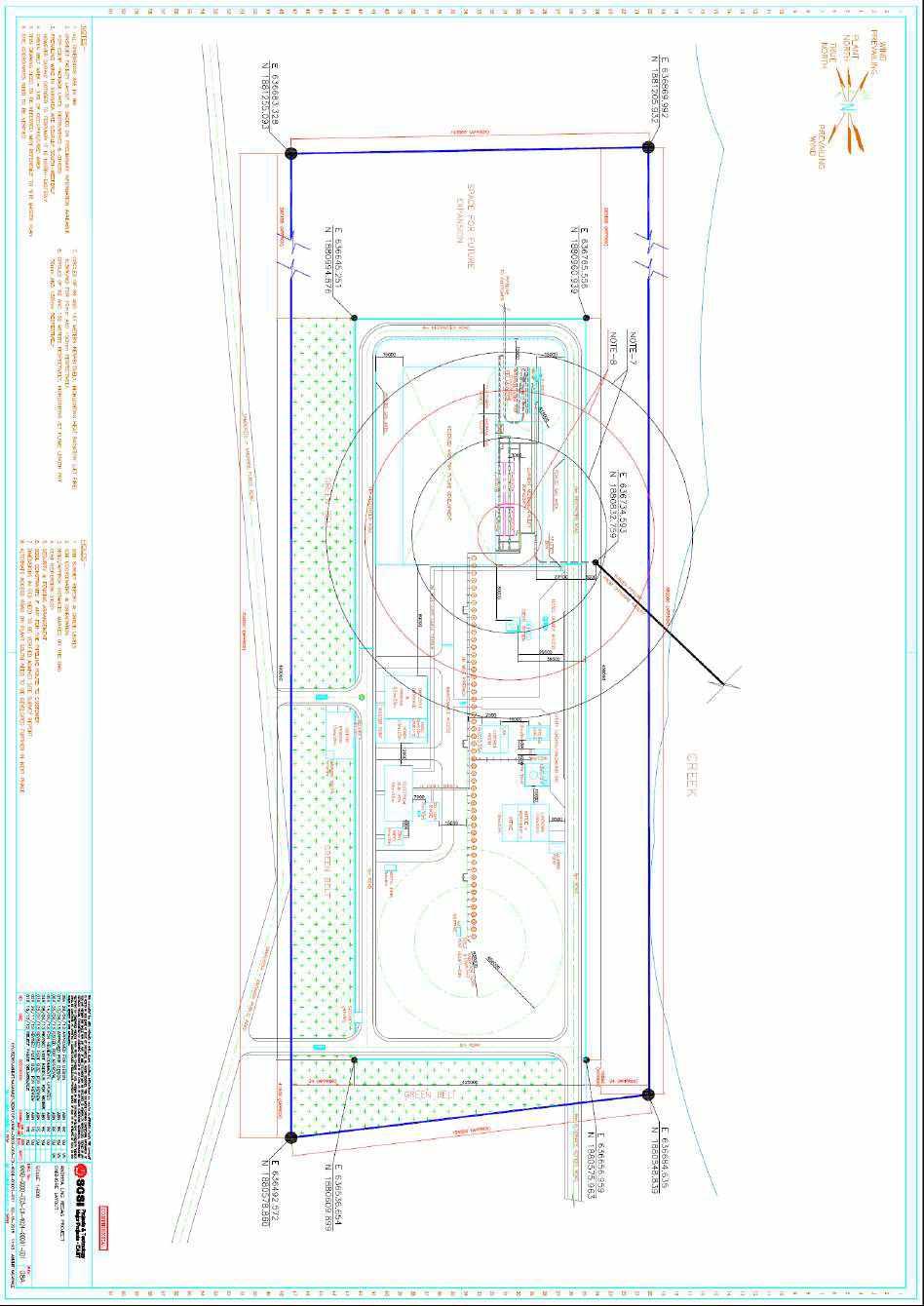
98 PH-84
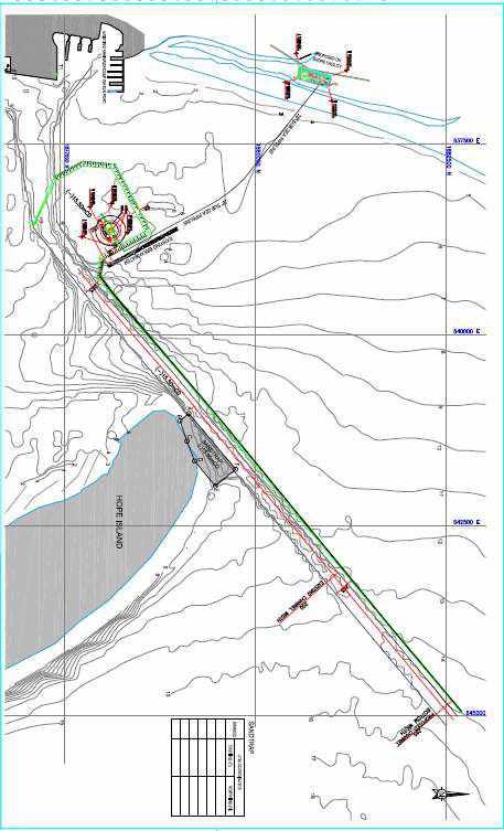
99 PH-85
Identification and Screening of Scenarios for LOPA. Ken First Dow Chemical Company Midland, MI
 Identification and Screening of Scenarios for LOPA Ken First Dow Chemical Company Midland, MI 1 Layers of Protection Analysis (LOPA) LOPA is a semi-quantitative tool for analyzing and assessing risk. The
Practical Modelling & Hazard Assessment of LPG & LNG Spills
 Practical Modelling & Hazard Assessment of LPG & LNG Spills UKELG 3 rd April 2012 Tony Ennis Introduction Refrigerated or pressurised Release scenarios & release rate Vaporisation Gas dispersion Consequences
Risks Associated with Caissons on Ageing Offshore Facilities
 Risks Associated with Caissons on Ageing Offshore Facilities D. Michael Johnson, DNV GL, Peter Joyce, BG Group, Sumeet Pabby, BG Group, Innes Lawtie, BG Group. Neil Arthur, BG Group, Paul Murray, DNV GL.
GAS TANKER COMMITTEE #4
 GAS TANKER COMMITTEE #4 FSRU-Critical link in Global LNG Supply chain Singapore 12 th October 2017 Lian-Gee CHUA, DNV GL 12 October 2017 1 SAFER, SMARTER, GREENER ABOUT DNV GL - The leading classification
PSM TRAINING COURSES. Courses can be conducted in multi-languages
 Courses can be conducted in multi-languages One set of hardcopy course notes will be sent to client for printing and distribution to course participants. The courses will be held at the client s training
INHERENTLY SAFER DESIGN CASE STUDY OF RAPID BLOW DOWN ON OFFSHORE PLATFORM
 INHERENTLY SAFER DESIGN CASE STUDY OF RAPID BLOW DOWN ON OFFSHORE PLATFORM Volton Edwards bptt Angus Lyon DNV Energy Alastair Bird DNV Energy INTRODUCTION A term now in common usage within the oil & gas
ANNEX AMENDMENTS TO THE INTERNATIONAL CODE FOR FIRE SAFETY SYSTEMS (FSS CODE) CHAPTER 15 INERT GAS SYSTEMS
 CHAPTER 15 INERT GAS SYSTEMS") Annex 3, page 2 ANNEX AMENDMENTS TO THE INTERNATIONAL CODE FOR FIRE SAFETY SYSTEMS (FSS CODE) CHAPTER 15 INERT GAS SYSTEMS The text of existing chapter 15 is replaced by the following: "1 Application This
Annex 3, page 2 ANNEX AMENDMENTS TO THE INTERNATIONAL CODE FOR FIRE SAFETY SYSTEMS (FSS CODE) CHAPTER 15 INERT GAS SYSTEMS The text of existing chapter 15 is replaced by the following: "1 Application This
DIGITAL SOLUTIONS TRAINING CATALOGUE. QRA and CFD simulation. Phast, Safeti and KFX SAFER, SMARTER, GREENER
 DIGITAL SOLUTIONS TRAINING CATALOGUE QRA and CFD simulation Phast, Safeti and KFX SAFER, SMARTER, GREENER 02 PHAST, SAFETI AND KFX Training catalogue Global training Our increased focus on global training,
Part 2.5 Dispersion Modeling Using ALOHA
 Part 2.5 Dispersion Modeling Using ALOHA Dr. Arshad Ahmad Email: arshad@utm.my 1 Software Commonly used for Risk Analysis Software SAFETI SFU CAFTAN ETRA HAZSEC. HAZTRAC. PHAST. WHAZAN EFFECTS. DAMAGE
AUSTRALIA ARGENTINA CANADA EGYPT NORTH SEA U.S. CENTRAL U.S. GULF. SEMS HAZARD ANALYSIS TRAINING September 29, 2011
 AUSTRALIA ARGENTINA CANADA EGYPT NORTH SEA U.S. CENTRAL U.S. GULF SEMS HAZARD ANALYSIS TRAINING September 29, 2011 Purpose The purpose of this meeting is to provide guidelines for determination of hazard
NEW IGC CODE AND IGF CODE
 NEW IGC CODE AND IGF CODE SAFETY ASPECTS Raffaele Piciocchi Gas Center - Greece SAFETY4SEAS - Athens 1 October 2014 Content NEW IGC CODE DRAFT IGF CODE 2 The New IGC Code A new IGC Code has been approved
A Generic Model To Assess Major Incident Frequencies For Offshore Assets
 A Generic Model To Assess Major Incident Frequencies For Offshore Assets Richard Emery, MMI Engineering Ltd, The Brew House, Wilderspool Park, Greenall s Avenue, Warrington, WA4 6HL. Quantitative risk
Improving Accuracy of Frequency Estimation of Major Vapor Cloud Explosions for Evaluating Control Room Location through Quantitative Risk Assessment
 Improving Accuracy of Frequency Estimation of Major Vapor Cloud Explosions for Evaluating Control Room Location through Quantitative Risk Assessment Naser Badri 1, Farshad Nourai 2 and Davod Rashtchian
Abstract. 1 Introduction
 Risk assessment study of the mutual interactive influence of working procedures on terminals handling dangerous goods in port of Koper (Slovenia) L. Battelino Water Management Institute, Maritime Engineering
Using Consequence Modeling to Help Make Emergency Decisions
 Using Consequence Modeling to Help Make Emergency Decisions Della Wong / Nova Chemicals & Robert B. Gerow / SAFER-ERMC CSChE 2002 Conference October 20-23, 23, 2002 Vancouver B.C. If auto safety was like
MAHB. INSPECTION Process Hazard Analysis
 Number 5 2016 seveso common MAHB INSPECTION s e r i e s criteria Process Hazard Analysis Major Accident Hazards Bureau Security Technology Assessment Unit This publication of the European community on
RESOLUTION MSC.397(95) (adopted on 11 June 2015) AMENDMENTS TO PART A OF THE SEAFARERS' TRAINING, CERTIFICATION AND WATCHKEEPING (STCW) CODE
 (adopted on 11 June 2015) AMENDMENTS TO PART A OF THE SEAFARERS' TRAINING, CERTIFICATION AND WATCHKEEPING (STCW) CODE") RESOLUTION MSC.397(95) (adopted on 11 June 2015) THE MARITIME SAFETY COMMITTEE, RECALLING Article 28(b) of the Convention on the International Maritime Organization concerning the functions of the Committee,
RESOLUTION MSC.397(95) (adopted on 11 June 2015) THE MARITIME SAFETY COMMITTEE, RECALLING Article 28(b) of the Convention on the International Maritime Organization concerning the functions of the Committee,
 Title of Paper Interpretation of IP15 in Process Plant Design: a Commonsense Approach ---------------------------------------------------------------------------------------------------------------------------
A large Layer of Protection Analysis for a Gas terminal scenarios/ cause consequence pairs
 A large Layer of Protection Analysis for a Gas terminal 2000+ scenarios/ cause consequence pairs Richard Gowland European process Safety Centre The scope of the study was a large gas terminal handling
Gerga Pressure Reduction Station
 The Quantitative Risk Assessment QRA Study For Gerga Pressure Reduction Station Prepared By Petroleum Safety and Environmental Services Company December 2015 Page 2 of 151 CONTENTS Executive Summary 12/151
THE SIGNIFICANCE OF HAZARD ENDPOINTS IN QUANTITATIVE RISK ANALYSIS
 THE SIGNIFICANCE OF HAZARD ENDPOINTS IN QUANTITATIVE RISK ANALYSIS John B. Cornwell and Jeffrey D. Marx Presented At 6 Process Plant Safety Symposium Houston, Texas April -2, 6 Presented By Quest Consultants
API MPMS Chapter 17.6 Guidelines for Determining the Fullness of Pipelines between Vessels and Shore Tanks
 API MPMS Chapter 17.6 Guidelines for Determining the Fullness of Pipelines between Vessels and Shore Tanks 1. Scope This document describes procedures for determining or confirming the fill condition of
Marine Risk Assessment
 Marine Risk Assessment Waraporn Srimoon (B.Sc., M.Sc.).) 10 December 2007 What is Risk assessment? Risk assessment is a review as to acceptability of risk based on comparison with risk standards or criteria,
Introduction to Emergency Response & Contingency Planning
 & Contingency Planning Rationale Why is it important for you to learn this material? Designed for those who may witness a release, this is an introductory course designed to help ensure those who are likely
Analysis of the application and sizing of pressure safety valves for fire protection on offshore oil and gas installations Annex I
 Analysis of the application and sizing of pressure safety valves for fire protection on offshore oil and gas installations Annex I Article draft The annex contains an article draft, based on an investigation
LNG TANDEM OFFLOADING A KEY ENABLING TECHNOLOGY TO MAKE LNG PRODUCTION OFFSHORE HAPPEN
 LNG TANDEM OFFLOADING A KEY ENABLING TECHNOLOGY TO MAKE LNG PRODUCTION OFFSHORE HAPPEN Fabrice Dumortier 1, Jean-Pierre Queau 1, Jean-Robert Fournier 2 1. SBM Offshore 2. SBM Offshore Keywords: 1. LNG;
PRAGMATIC ASSESSMENT OF EXPLOSION RISKS TO THE CONTROL ROOM BUILDING OF A VINYL CHLORIDE PLANT
 PRAGMATIC ASSESSMENT OF EXPLOSION RISKS TO THE CONTROL ROOM BUILDING OF A VINYL CHLORIDE PLANT L.P. Sluijs 1, B.J. Haitsma 1 and P. Beaufort 2 1 Vectra Group Ltd. 2 Shin-Etsu (contact details: Vectra Group
Tema Pressure Reduction Station
 The Quantitative Risk Assessment QRA Study For Tema Pressure Reduction Station Prepared By Petroleum Safety and Environmental Services Company January 2016 EGAS.HSE.QRA.Study.PRS.02/Tema.No.02/2015/QRA/MG/MS/DNV-PHAST.7.0--Final
LNG Marine Loading Arms and Manifold Draining, Purging and Disconnection Procedure
 LNG Marine Loading Arms and Manifold Draining, Purging and Disconnection Procedure i The Society of International Gas Tanker and Terminal Operators (SIGTTO) The Society of International Gas Tanker and
Evaluation of Northwest Citizen Science Initiative (NWCSI) March 7,2015 Report Summary
 March 7,2015 Report Summary") Memo to: Memo No.: 1MIJD63-1/ LLAT Rev 1 Chris Hayes Prepared by: Lindsay Deal Senior Consultant Date: 30 March 2015 Copied to: Eric Dyck, Gail Feltham, Dennis O Mara, Cynthia Reviewed by: Tone Rice Head
Memo to: Memo No.: 1MIJD63-1/ LLAT Rev 1 Chris Hayes Prepared by: Lindsay Deal Senior Consultant Date: 30 March 2015 Copied to: Eric Dyck, Gail Feltham, Dennis O Mara, Cynthia Reviewed by: Tone Rice Head
Safety in Petroleum Industry
 Chemical ( Industrial ) Disaster Management Conference, Bangalore 30 January 2014 Safety in Petroleum Industry Refineries and Petrochemical plants are highly energyintensive Handle highly inflammable and
Process Safety Management Of Highly Hazardous Chemicals OSHA 29 CFR
 Process Safety Management Of Highly Hazardous Chemicals OSHA 29 CFR 1910.119 PSM - Definition Not all refining hazards are caused by the same factors or involve ve the same degree of potential damage.
Introduction to HAZOP Study. Dr. AA Process Control and Safety Group
 Introduction to HAZOP Study Dr. AA Process Control and Safety Group A scenario You and your family are on a road trip by using a car in the middle of the night. You were replying a text message while driving
RESOLUTION A.567(14) adopted on 20 November 1985 REGULATION FOR INERT GAS SYSTEMS ON CHEMICAL TANKERS
 adopted on 20 November 1985 REGULATION FOR INERT GAS SYSTEMS ON CHEMICAL TANKERS") INTERNATIONAL MARITIME ORGANIZATION A 14/Res.567 16 January 1986 Original: ENGLISH ASSEMBLY - 14th session Agenda item lo(b) IMO RESOLUTION A.567(14) adopted on 20 November 1985 THE ASSEMBLY, RECALLING
INTERNATIONAL MARITIME ORGANIZATION A 14/Res.567 16 January 1986 Original: ENGLISH ASSEMBLY - 14th session Agenda item lo(b) IMO RESOLUTION A.567(14) adopted on 20 November 1985 THE ASSEMBLY, RECALLING
Fire and Safety for Offshore drilling and production Ajey Walavalkar ANSYS Inc.
 Fire and Safety for Offshore drilling and production Ajey Walavalkar ANSYS Inc. 1 ANSYS, Inc. September 12, Fire and safety related applications Gas Dispersion and Ventilation Formation of combustible
Minimum standard of competence in advanced training for liquefied gas tanker cargo operations (STCW Reg V/1-2)
") Minimum standard of in advanced training for liquefied gas tanker cargo operations (STCW Reg V/1-2) Column 2 Knowledge, understanding and proficiency Design and characteristics of a liquefied gas tanker
Minimum standard of in advanced training for liquefied gas tanker cargo operations (STCW Reg V/1-2) Column 2 Knowledge, understanding and proficiency Design and characteristics of a liquefied gas tanker
NORMAL OPERATING PROCEDURES Operating Parameter Information
 Operating Parameter Information Each operator performing the normal operating procedures (routine checks) of the facility should be familiar with the current normal operating parameters of all systems
SAFETI OFFSHORE. Modelling of the progression of an offshore hydrocarbon release accident WHITEPAPER. Authors:
 WHITEPAPER SAFETI OFFSHORE Modelling of the progression of an offshore hydrocarbon release accident Authors: Brian Bain, DNV GL, Aberdeen. E-mail : brian.bain@dnvgl.com David Worthington, DNV GL, London.
USE OF THE EXCEEDANCE CURVE APPROACH IN OCCUPIED BUILDING RISK ASSESSMENT
 USE OF THE EXCEEDANCE CURVE APPROACH IN OCCUPIED BUILDING RISK ASSESSMENT Kieran J Glynn, Advisor Major Accident Risk, BP, UK The exceedance curve approach was developed following the issue of the 2003
Figure-28 shows the methodology adopted for the rapid risk assessment of the drilling operation.
 Chapter 7:Additional Studies 7.1. Risk Assessment Work Over of the temporarily abandoned sweet gas well and drilling 5 nos. of additional appraisal / development well in an area of 9.63 sq. km of Achanta
STCW Code Table A-V/1-1-1 Specification of minimum standard of competence in basic training for oil and chemical tanker cargo operations
 STCW Code Table A-V/1-1-1 Specification of minimum standard of in basic for oil and chemical tanker cargo operations Ref: https://www.edumaritime.net/stcw-code Source: IMO Contribute to Basic knowledge
Improvement in Release Frequencies for Quantitative Risk Assessment
 Improvement in Release Frequencies for Quantitative Risk Assessment Andrew Crerand, Simon Chynoweth and Steve Richardson, Shell Research Ltd, Shell Technology Centre Thornton, P.O. Box 1, Chester, CH1
Periodical surveys of cargo installations on ships carrying liquefied gases in bulk
 (June 1999) (Rev.1 Mar 2006) (Rev.2 May 2007) (Rev.3 Mar 2010) (Corr.1 Feb 2011) (Rev.4 Oct 2013) Periodical surveys of cargo installations on ships carrying liquefied gases in bulk 1 General 1.1 Scope
Annexure 2: Rapid Risk Assesment RISK ANALYSIS
 RISK ANALYSIS (I) Catastrophic Rupture of LPG Bullet Truck (18 MT) At the LPG bottling plant, LPG will be transported by Bullet Truck tank. In the event of fire in LPG bullet truck in parking area, BLEVE
Uncertainty in the analysis of the risk of BLEVE Fireball in process plants and in transportation
 Uncertainty in the analysis of the risk of BLEVE Fireball in process plants and in transportation Joaquim Casal Centre for Studies on Technological Risk (CERTEC) EEBE, Universitat Politècnica de Catalunya
Modelling Hazardous Consequences of a Shale Gas Well Blowout
 Modelling Hazardous Consequences of a Shale Gas Well Blowout Sergey Martynov & Haroun Mahgerefteh (UCL) ShaleX Dissemination Event Texas A&M, Doha, Qatar 18 March 2018 1 Presentation Scope Motivation and
Inherently Safer Design Analysis Approaches
 Inherently Safer Design Analysis Approaches There are a number of ways inherent safety can be analyzed. In any case, the intent is to formalize the consideration of inherent safety rather than to include
Impact on People. A minor injury with no permanent health damage
 Practical Experience of applying Layer of Protection Analysis For Safety Instrumented Systems (SIS) to comply with IEC 61511. Richard Gowland. Director European Process Safety Centre. (Rtgowland@aol.com,
Understanding safety life cycles
 Understanding safety life cycles IEC/EN 61508 is the basis for the specification, design, and operation of safety instrumented systems (SIS) Fast Forward: IEC/EN 61508 standards need to be implemented
Well Integrity - Christmas Tree Acceptable Leakage Rate and Sustained Casing Pressure
 Well Integrity - Christmas Tree Acceptable Leakage Rate and Sustained Casing Pressure Mrudhul Raj, Atkins Ltd, Aberdeen, UK The loss of well integrity can result in major accidents and presents a severe
THE BAKER REPORT HOW FINDINGS HAVE BEEN USED BY JOHNSON MATTHEY TO REVIEW THEIR MANUFACTURING OPERATIONS
 THE BAKER REPORT HOW FINDINGS HAVE BEEN USED BY JOHNSON MATTHEY TO REVIEW THEIR MANUFACTURING OPERATIONS Colin P. Lynas, Elizabeth Campbell and Hendrik J. Koornhof Johnson Matthey Catalysts This paper
DETERMINATION OF SAFETY REQUIREMENTS FOR SAFETY- RELATED PROTECTION AND CONTROL SYSTEMS - IEC 61508
 DETERMINATION OF SAFETY REQUIREMENTS FOR SAFETY- RELATED PROTECTION AND CONTROL SYSTEMS - IEC 61508 Simon J Brown Technology Division, Health & Safety Executive, Bootle, Merseyside L20 3QZ, UK Crown Copyright
Responding to Natural Gas Pipeline Emergencies
 Responding to Natural Gas Pipeline Emergencies Who is Florida Gas Transmission? Florida Gas Transmission operates nearly 5,000-miles of interstate natural gas transmission pipelines, a system that extends
BASF Flash Fire FRC Assessment Tool
 BASF Flash Fire FRC Assessment Tool Introduction The assessment tool offered in this document was developed to assist BASF manufacturing units in evaluating the potential for flash fire occurrence and
Caltec. The world leader in Surface Jet Pump (SJP) and compact separation systems for upstream oil and gas production enhancement
 and compact separation systems for upstream oil and gas production enhancement") Caltec brings simple passive technology that enables oil and gas operators to harness the kinetic energy of the production process to enhance their production, extending economic field life and reducing
Caltec brings simple passive technology that enables oil and gas operators to harness the kinetic energy of the production process to enhance their production, extending economic field life and reducing
Pipeline Integrity Valve Spacing Engineering Assessment (CDN) Grande Prairie Mainline Loop 2 (Progress Section) NPS 36
 Grande Prairie Mainline Loop 2 (Progress Section) NPS 36") APPROVALS Library: EDMS General Page 1 of 10 TABLE OF CONTENTS APPROVALS 1 1. PURPOSE... 3 2. BACKGROUND... 3 3. VALVE SPACING ASSESSMENT APPROACH... 6 4. OPERATIONS AND MAINTENANCE CONSIDERATIONS... 6
APPROVALS Library: EDMS General Page 1 of 10 TABLE OF CONTENTS APPROVALS 1 1. PURPOSE... 3 2. BACKGROUND... 3 3. VALVE SPACING ASSESSMENT APPROACH... 6 4. OPERATIONS AND MAINTENANCE CONSIDERATIONS... 6
INTERNATIONAL ASSOCIATION OF CLASSIFICATION SOCIETIES. Interpretations of the. IGF Code
 INTERNATIONAL ASSOCIATION OF CLASSIFICATION SOCIETIES s of the IGF Code CONTENTS GF1 Test for gas fuel tank s high level alarm Rev.1 July 2017 GF2 Ship Steel Protection against Liquefied Gas Fuel (Part
State of the Art in the Technical Assessment of DOMINO EFFECT
 State of the Art in the Technical Assessment of DOMINO EFFECT Valerio Cozzani LISES - DICAM, Alma Mater Studiorum - Università di Bologna, Bologna, Italy DOMINO EFFECT: Requirements for the control of
Development of Accidental Collapse Limit State Criteria for Offshore Structures
 Risk Acceptance and Risk Communication Stanford, March 26-27, 2007 Development of Accidental Collapse Limit State Criteria for Offshore Structures by Torgeir Moan Norwegian University of Science and Technology
EXPLOSIVE ATMOSPHERES - CLASSIFICATION OF HAZARDOUS AREAS (ZONING) AND SELECTION OF EQUIPMENT
 AND SELECTION OF EQUIPMENT") EXPLOSIVE ATMOSPHERES - CLASSIFICATION OF HAZARDOUS AREAS (ZONING) AND SELECTION OF EQUIPMENT OVERVIEW ASSESSING THE RISK RELATIONSHIP BETWEEN FIRES AND EXPLOSIONS CLASSIFYING HAZARDOUS AREAS INTO ZONES
EXPLOSIVE ATMOSPHERES - CLASSIFICATION OF HAZARDOUS AREAS (ZONING) AND SELECTION OF EQUIPMENT OVERVIEW ASSESSING THE RISK RELATIONSHIP BETWEEN FIRES AND EXPLOSIONS CLASSIFYING HAZARDOUS AREAS INTO ZONES
There are three fuelling systems which use LNG/CNG and which may be found in vehicles today:
 UKRO Humberside Education Workshop 2017 NATURAL GAS POWERED VEHICLES Some LGV manufacturers (currently IVECO and SCANIA) are able to offer and Alternative Fueled vehicles that use Compresses Natural Gas
OPERATIONS SEAFARER CERTIFICATION
 Page 1 of 6 Compiled by Chief Examiner Approved by Qualifications Committee: 25 November 2013 OPERATIONS SEAFARER CERTIFICATION GUIDANCE NOTE SA MARITIME QUALIFICATIONS CODE Ancillary : Basic Training
CHE Well Testing Package/Service:
 CHE Well Testing Package/Service: CHE delivers well testing package And services, trailer mounted well testing package and offshore/onshore well testing services with over 10 years experience. Our testing
REGASIFICATION VESSELS
 CLASSICATION NOTES No. 61.3 REGASICATION VESSELS MAY 2011 The content of this service document is the subject of intellectual property rights reserved by Det Norske Veritas AS (DNV). The user accepts that
The Risk of LOPA and SIL Classification in the process industry
 The Risk of LOPA and SIL Classification in the process industry Mary Kay O Connor Process Safety Center International Symposium Beyond Regulatory Compliance, Making Safety Second Nature October 28-29,
Hazard Operability Analysis
 Hazard Operability Analysis Politecnico di Milano Dipartimento di Energia HAZOP Qualitative Deductive (search for causes) Inductive (consequence analysis) AIM: Identification of possible process anomalies
SEMS II: BSEE should focus on eliminating human error
 SEMS II: BSEE should focus on eliminating human error How US companies can prevent accidents on start-ups and shut-downs by using valve interlocks The proposed changes to BSEE s SEMS (Safety and Environmental
Process Equipment Exposed to Fire. A Case Study on the Behaviour of a Fire Exposed LNG Segment.
 Process Equipment Exposed to Fire. A Case Study on the Behaviour of a Fire Exposed LNG Segment. Arve Klavenes and Geir Berge Petrell AS Kjøpmannsgata 19, NO-713 Trondheim, Norway When pressurized equipment
Using LOPA for Other Applications
 10 Using LOPA for Other Applications 10.1. Purpose LOPA is a tool used to perform risk assessments. Previous chapters described its use in assessing the risk level of process hazards scenarios and in evaluating
Blast Damage Consideratons for Horizontal Pressure Vessel and Potential for Domino Effects
 A publication of CHEMICAL ENGINEERING TRANSACTIONS VOL. 26, 2012 Guest Editors: Valerio Cozzani, Eddy De Rademaeker Copyright 2012, AIDIC Servizi S.r.l., ISBN 978-88-95608-17-4; ISSN 1974-9791 The Italian
USE OF RISK ANALYSIS FOR EMERGENCY PLANNING OF LNG CARRIERS
 USE OF RISK ANALYSIS FOR EMERGENCY PLANNING OF LNG CARRIERS Mr. Erik Skramstad, Det Norske Veritas, Norway; Mrs. Stine U. Musaeus, Det Norske Veritas, Norway; Capt. Steingrim Melbeo, Osprey Maritime, UK.
USING HAZOP TO IDENTIFY AND MINIMISE HUMAN ERRORS IN OPERATING PROCESS PLANT
 USING HAZOP TO IDENTIFY AND MINIMISE HUMAN ERRORS IN OPERATING PROCESS PLANT Chris Lyth, Tracerco, Billingham, Cleveland, UK Ian Bradby, ABB Engineering Services, Billingham Cleveland, UK This joint paper
LNG Cargo Operations. Juan Manuel Martín Ordax
 Juan Manuel Martín Ordax If we consider that the gas carrier is coming directly from a shipbuilder or a drydock, the sequence of cargo operations would be as follows: Source: Liquefied Gas Handling Principles
Periodic Survey of Fuel Installations on Ships other than Liquefied Gas Carriers utilizing gas or other low flash point fuels
 (Jan 2017) Periodic Survey of Fuel Installations on Ships other than Liquefied Gas Carriers utilizing gas or other low flash point fuels CONTENTS 1. Application 2. Special Survey 2.1 Schedule 2.2 Scope
Vision Painting Inc Safety Management System
 Abrasive Blasting 1. PURPOSE The purpose of this program is to provide training and qualification guidelines for the safe operation of Abrasive Blasting. The Safety Officer is responsible for facilitating
Safety Engineering - Hazard Identification Techniques - M. Jahoda
 Safety Engineering - Hazard Identification Techniques - M. Jahoda Hazard identification The risk management of a plant 2 Identification of the hazards involved in the operation of the plant, due to the
Every things under control High-Integrity Pressure Protection System (HIPPS)
") Every things under control www.adico.co info@adico.co Table Of Contents 1. Introduction... 2 2. Standards... 3 3. HIPPS vs Emergency Shut Down... 4 4. Safety Requirement Specification... 4 5. Device Integrity
Every things under control www.adico.co info@adico.co Table Of Contents 1. Introduction... 2 2. Standards... 3 3. HIPPS vs Emergency Shut Down... 4 4. Safety Requirement Specification... 4 5. Device Integrity
USING PREDICTIVE RISK ASSESSMENTS TO DEVELOP USER-FRIENDLY TOOLS FOR ON- AND OFF-SITE EMERGENCY PLANNING
 USING PREDICTIVE RISK ASSESSMENTS TO DEVELOP USER-FRIENDLY TOOLS FOR ON- AND OFF-SITE EMERGENCY PLANNING Jo Fearnley and SreeRaj R Nair Aker Solutions, Phoenix House, 3 Surtees Way, Surtees Business Park,
Quantitative Risk Assessment (QRA) For
 For") Quantitative Risk Assessment (QRA) Report For Indian Oil Corporation Limited Gurgaon - LPG Bottling Plant By Ultra-Tech Environmental Consultancy April 2017 IOCL GURGAON LPG BOTTLING PLANT, REV B1 Page
Quantitative Risk Assessment (QRA) Report For Indian Oil Corporation Limited Gurgaon - LPG Bottling Plant By Ultra-Tech Environmental Consultancy April 2017 IOCL GURGAON LPG BOTTLING PLANT, REV B1 Page
Failure analysis of storage tank component in LNG regasification unit using fault tree analysis method (FTA)
") Failure analysis of storage tank component in LNG regasification unit using fault tree analysis method (FTA) Cukup Mulyana, Fajar Muhammad, Aswad H. Saad, Mariah, and Nowo Riveli Citation: AIP Conference
Failure analysis of storage tank component in LNG regasification unit using fault tree analysis method (FTA) Cukup Mulyana, Fajar Muhammad, Aswad H. Saad, Mariah, and Nowo Riveli Citation: AIP Conference
Absorption - The process of contacting a vapor and gas stream with an absorbing liquid to remove specific materials from the gas stream.
 Sufe Design and Optvation ofpi-oc.ess Vents and Emission Contid $wteins by Center for Chemical Process Safety Copyright 0 2006 John Wiley & Sons, Tnc. APPENDIX B GLOSSARY Absorption - The process of contacting
User Information Sheet 015
 User Information Sheet 015 Formerly LPGA Guidance NO.84 March 2007 Inspection and Maintenance of LPG Pipework at Commercial and Industrial Premises 1. Introduction LPG pipework may, under certain conditions,
Fitness for Service Assessment of Ageing Pressure Vessel Experiencing External Corrosion: A Case Study
 The International Journal Of Engineering And Science (IJES) Volume 6 Issue 2 Pages PP 12-16 2017 ISSN (e): 2319 1813 ISSN (p): 2319 1805 Fitness for Service Assessment of Ageing Pressure Vessel Experiencing
Process Safety Journey
 Process Safety Journey Agenda The Status in early 2000s The Journey to improvement in Process Safety management Managing risks and barriers How has this impacted Kwinana? The Status in early 2000s Focus
IGEM/TD/2 Edition 2 with amendments July 2015 Communication 1779 Assessing the risks from high pressure Natural Gas pipelines
 Communication 1779 Assessing the risks from high pressure Natural Gas pipelines Founded 1863 Royal Charter 1929 Patron: Her Majesty the Queen Communication 1779 Assessing the risks from high pressure Natural
OLGA. The Dynamic Three Phase Flow Simulator. Input. Output. Mass transfer Momentum transfer Energy transfer. 9 Conservation equations
 서유택 Flow Assurance The Dynamic Three Phase Flow Simulator 9 Conservation equations Mass (5) Momentum (3) Energy (1) Mass transfer Momentum transfer Energy transfer Input Boundary and initial conditions
Installation of Ballast Water Management Systems
 (Sept 2015) (Rev.1 May 2016) Installation of Ballast Water Management Systems 1. Application In addition to the requirements contained in BWM Convention (2004), the following requirements are applied to
COMMON MISUNDERSTANDINGS ABOUT THE PRACTICAL APPLICATION OF IEC 61508
 COMMON MISUNDERSTANDINGS ABOUT THE PRACTICAL APPLICATION OF IEC 61508 Helen Pearce, James Catmur and Geoff Stevens The use of IEC 61508 for determination of the Safety Integrity Level (SIL) of Safety Interlock
SLOP RECEPTION AND PROCESSING FACILITIES
 RULES FOR CLASSIFICATION OF SHIPS NEWBUILDINGS SPECIAL SERVICE AND TYPE ADDITIONAL CLASS PART 5 CHAPTER 8 SLOP RECEPTION AND PROCESSING FACILITIES JANUARY 2011 CONTENTS PAGE Sec. 1 General Requirements...
DECLARATION OF INCORPORATION
 AESSEAL (MCK) Ltd. Systems Division 139a Hillsborough Old Road Lisburn Northern Ireland BT27 5QE Tel +44 (0) 2892 669966 Fax +44 (0) 2892 669977 When selecting and installing suitable Barrier Fluid System
SAFETY SEMINAR Rio de Janeiro, Brazil - August 3-7, Authors: Francisco Carlos da Costa Barros Edson Romano Marins
 SAFETY SEINAR Rio de Janeiro, Brazil - August 3-7, 2009 Using HAZOP and LOPA ethodologies to Improve Safety in the Coke Drums Cycles Authors: Gilsa Pacheco onteiro Francisco Carlos da Costa Barros Edson
FV Flash Vessel Installation and Maintenance Instructions
 4041050/5 IM-P404-10 EMM Issue 5 FV Flash Vessel Installation and Maintenance Instructions 1. Safety information 2. Specific product safety information 3. Product information 4. Installation 5. Commissioning
EIA Studies for the Development of CBM Activities in Jharia CBM Block
 Risk Assessment EIA Studies for the Development of CBM Activities in Jharia CBM Block Prepared for: Oil and Natural Gas Corporation Limited Prepared by: SENES Consultants India Pvt. Ltd. December, 2015
Tanker Familiarisation IMO Model Course Chapter 1-9
 IMO Model Course 1.01 Chapter 1-9 - Courseware Specification - MarineSoft Entwicklungs- und Logistikgesellschaft mbh Friedrich-Barnewitz-Straße 2 18119 Rostock GERMANY +49 381 12835-0 +49 381 12835-55
Air Eliminators and Combination Air Eliminators Strainers
 Description Air Eliminators and Combination Air Eliminator Strainers are designed to provide separation, elimination and prevention of air in piping systems for a variety of installations and conditions.
The Protection of Silos From Over. Pressurisation During Filling
 SHAPA Technical Bulletin No.11 The Protection of Silos From Over Pressurisation During Filling Page 1 of 8 August 2005 The Protection of Silos From Over Pressurisation During Filling By James Duggleby,
SAFETY TRAINING LEAFLET 06 CARBON DIOXIDE
 SAFETY TRAINING LEAFLET 06 CARBON DIOXIDE Doc 23.06/18 EUROPEAN INDUSTRIAL GASES ASSOCIATION AISBL AVENUE DES ARTS 3-5 B 1210 BRUSSELS Tel: +32 2 217 70 98 Fax: +32 2 219 85 14 E-mail: info@eiga.eu Internet:
Addendum 4 Levels of Response
 Addendum 4 Levels of Response Levels of Response to a Hazardous Materials Incident A. Criteria for Categorization Hazardous materials incidents are categorized as Level I, II, or III depending on the severity
CONCLUSIVE SUMMARY OF CARBON DIOXIDE
 Introduction CONCLUSIVE SUMMARY OF CARBON DIOXIDE Cintra is developing a CO 2 Liquid Logistics Shipping Concept (LLSC) that will provide CO 2 emitters a complete logistical transportation solution for
CFD Based Approach for VCE Risk Assessment
 CFD Based Approach for VCE Risk Assessment 2009 MKOPSC International Symposium Anna Qiao, Steven Zhang, Asmund Huser DNV Energy Objective Determine the maximum design load at a specified frequency Provide