Unimatic II Manifolds for Oxygen, Nitrous Oxide & Nitrogen Service Manual
|
|
|
- Adele Hodge
- 6 years ago
- Views:
Transcription
1 Unimatic II Manifolds for Oxygen, Nitrous Oxide & Nitrogen Service Manual BOC Health Care
2 Important The information contained in this service manual pertains only to those models of this Product which are marketed by Ohio as of the effective date of this manual or the latest revision thereof. This service manual was prepared for exclusive use by Ohio service personnel in light of their training and experience as well as the availability to them of proper tools and test equipment. Consequently, Ohio provides this service manual to its customers purely as a business convenience and for the customer's general information only without warranty of the results with respect to any application of such information. Furthermore, because of the wide variety of circumstances under which maintenance and repair activities may be performed and the unique nature of each individual's own experience, capacity, and qualifications, the fact that customer has received said information from Ohio does not imply in any way that Ohio deems said individual to be qualified to perform any such maintenance or repair service. Moreover, it should not be assumed that every acceptable test and safety procedure or method, precaution, tool, equipment or devices which could be used in servicing this Product is referred to within, or that abnormal or unusual circumstances may not warrant or suggest different or additional procedures or requirements. This manual is subject to periodic review and customers are cautioned to obtain and consult the latest revision thereof before undertaking any service of the Product. Comments and suggestions are invited from our customers for consideration by Ohio in connection with these periodic reviews. WARNING: Read all of the warnings and cautions as listed in the Precautions section of this manual before attempting to perform any of the procedures described in this manual. CAUTION: Servicing of this Product in accordance with this service manual should never be undertaken In the absence of proper tools, test equipment and the most recent revision to this service manual which Is clearly and thoroughly understood.
3 Precautions Table of Contents 1/ Description 3 2/ Operation 2.1 Theory of Operation Cylinder Installation Gas Flow and Manifold Operation Bypass Mode of Operation 14 3/ Maintenance 3.1 General Regulator Adjustment Pressure Switch Checking and Adjustment Switch Over Indicator Circuit Check-Out Switch Over Indicator Circuit-Troubleshooting Information Pressure Switch Electrical Check-Out Switch Over Indicator Circuit Repairs Pneumatic Switch Over Circuit Check-Out Pneumatic Circuit-Troubleshooting Information Oxygen, Nitrous Oxide and Nitrogen Bank Regulator Replacement Oxygen, Nitrous Oxide and Nitrogen Delivery Line Regulator Replacement Shuttle Valve Replacement Intermediate Pressure Check Valve Replacement Intermediate Line Relief Valve Test Relief Valve Replacement-Intermediate Line Bank Pressure Gauge Replacement Delivery Line Pressure Gauge Replacement Intermediate Pressure Gauge Replacement Pressure Switch Replacement Relief Valve Replacement-Delivery Line Bleed Valve Replacement Bypass Valve Replacement Manifold Shut-Down Procedure 40 4/ Illustrated Parts List 41 Cover Photo Oxygen Unimatic II Manifold- Four Cylinder, Wall Mounted Model Stock No
4 Precautions Technical Competence The procedures described in this service manual should be performed by trained and authorized personnel only. Maintenance should only be undertaken by competent individuals who have a general knowledge of and experience with devices of this nature. No repairs should ever be undertaken or attempted by anyone not having such qualifications. Genuine replacement parts manufactured or sold by Ohio Medical Products must be used for all repairs. Read completely through each step in every procedure before starting the procedure; any exceptions may result in a failure to properly and safely complete the attempted procedure. Warnings FIRE HAZARD. DO NOT permit smoking or any other source of ignition in area where the manifold is located or near relief valve vent outlet. Be certain all connections are free of dirt, grease and oil. These substances burn with great intensity in air enriched with oxygen or nitrous oxide. See Pages 12 and 16. When the BYPASS MODE is in use NO SECONDARY SUPPLY IS AVAILABLE. Gas is being supplied directly and only from the left bank regulator at line pressure. Monitor pressure in left bankreestablish normal operation BEFORE the left bank nears depletion. See Page 14. To ensure proper functioning and proper delivery of gas, EACH, regulator must be adjusted while gas is flowing through the regulator as indicated in the following procedure. ALL bank regulator pressure settings must be made with a supply pressure of 600 psig or greater for nitrous oxide (N20) and 1800 psig or greater for oxygen (02) and nitrogen (N2). The delivery line must be set with an inlet pressure (intermediate line pressure) of 200 psig ± 10 psig on 02 and N20 manifolds, and 400 psig ± 10 psig on N2 manifolds. See Pages 14 and 18. The left and right banks must have sufficient gas volume to perform any test and supply hospital demand. See pages 16, 22 and 27. Never oil or grease oxygen or nitrous oxide equipment unless a lubricant that is made and approved for this type of service (such as Vac-Kote, Stock No ) is used or a certain type of lubricant is specified for a particular part of a unit. Oils and greases oxidize readily and, in the presence of oxygen, will burn violently. See Page 16. Use extreme care, when working with high pressure oxygen components and systems, to keep hands, tools and work environment free of oils which are highly combustible in the presence of high pressure oxygen. See Page 16. The person performing service on the manifold is responsible for obtaining permission from the hospital administration prior to performing any check-out or repairs of the manifold. See Page 16. 1
5 Precautions Warnings Continued Only one header valve may be turned off while the manifold is supplying gas to the hospital. After performing checks or making repairs return header valves to the open position. See Pages 16, 22 and 27. Nitrous oxide is in liquid form in the cylinders (at above 800 psig). Therefore, both bank pressure gauges may indicate the same pressure although the liquid level in one bank may be lower. The possibility of a bank depletion occuring while service is being performed should be avoided. The installation of one or two full Nitrous Oxide cylinders for the duration of the repair or test procedure will prevent this. See Page 16. To ensure a continuous supply of gas during regulator adjustment, be certain ample supply of gas is available in both cylinder banks and NEVER close a header valve unless the opposite bank header valve is open. See Page 18. To ensure flow of gas to the delivery line during the pressure switch checking and adjustment procedure, BE CERTAIN sufficient supply is available in both cylinder banks. During the checking and adjustment procedure, bank regulator pressure settings must be changed and readjusted as necessary. To ensure proper flow to the delivery line, the bank regulator adjustment must be made with an inlet (cylinder) pressure of 1800 psig or greater for 02 and N2, and 600 psig or greater for N20. See Page 20. Do NOT interchange indicator light lenses-upper light lens is RED, lower light lens is GREEN. See Page 25. Disconnect electricity to the unit before attempting any electrical component repairs. See pages 25 and 26. Only one header valve may be turned off while the manifold is supplying gas to the hospital. After performing checks or making repairs return the header valves to the open position. See Page 27. Do not use oil or oilbearing materials on or near regulators. Oils and greases oxidize readily and, in the presence of oxygen, they will burn violently. Nonmetallic parts of regulators must be discarded permanently if contaminated with oil or grease. DO NOT LUBRICATE REGULATOR PARTS. See Pages 29 and 30. Cautions Do NOT repeatedly bend, sharply bend or twist copper tubing as damage to the tubing may result. See Page 12. Each pigtail must be connected to a cylinder to prevent gas leaks. The header connection to the pigtail is equipped with a check valve; however, this valve is not leak free. If an inlet is not to be used, be certain the pigtail is removed and the header inlet is securely sealed with a blind gland and nut. See Page 12. Repair of the Unimatic II 02, N20 and N2 manifolds should not be undertaken until all required tools, test equipment, and special materials that may be required are available. See Page 16. The pressure at which the pressure switch is set to indicate switchover must be checked as pressure in the intermediate line drops. See Pages 20 and 22. 2
6 1/ Description Figure 1. Nitrogen Unimatic II Manifold- Twelve Cylinder, Free Standing Model Stock No General Unimatic II Manifolds are available in wall mounted models (Cover Photo) or free standing models (Figure 1) providing oxygen (02), nitrous oxide (N20), or nitrogen (N2) gas service. The manifolds are designed to deliver low pressure (50 psig on 02 and N20 manifolds or 180 psig on N2 manifolds) medical gas from high pressure (3000 psig max) cylinders. The number of cylinders which can be accommodated by the various manifolds is given in Table 1 on Page 4. The Unimatic II Manifolds provide for left and right cylinder banks of equal capacity as illustrated in Figure 2. When one bank is exhausted, the manifold automatically switches to supply gas from the other bank. Indicator lights on the pressure control cabinet (and at remote alarm panels, if used) indicate the switch over. Gauges on the front of the control cabinet continuously indicate pressures within the left cylinder bank, the right cylinder bank, and the delivery line. The manifolds are also equipped with a bypass system whereby gas can be supplied directly (at delivery pressure) from the left cylinder bank regulator. This feature provides supply in emergency situations and also permits servicing of the delivery line regulator and switch over system without interrupting the supply of gas. 3
7 1/ Description Table 1. Unimatic II Manifolds - Models, Cylinders and Approximate Capacity Gas Service Free Standing Wall Mounted Total Cu Ft Model Stock No. Model Stock No. Number Capacity* (cylinders (cylinders of Cylinders (with H size not included) not included) cylinders) , , ,440 Oxy gen ,928 (02) , , , , , , , , , , ,684 Nitrous Oxide ,798 (N20) ,912 Nitrogen (N2) NN CoCO0NCDCO0N , , , , , , , ,688 ' Approximate capacity based on "full" H size cylinder contents at Normal Temperature and Pressure; 244 cu ft/02 cylinder, 557 Cu ft/n20 cylinder, and 224 cu ft/n2 cylinder., -. Left Bank I.- N Control C T r), i, \ \., I Cabinet _ i, Bcylinders Right Bank L e f t Bank r" Control ) i Cabinet 14 cylinders Right Bank Figure 2. Examples of Cylinder Bank Configurations 4
8 1/ Description Left Header Valve Left Bank Pressure Gauge r - L - _a....c>t1m Left Intermediate Pressure Gauge Left Pressure Switch Left Bank I - Regulator V T Left Relief T Valve \"/ Shuttle Valve By-Pass Valve I=C) I Right Relief Valve - _ -/ Right Bank Right intermediate Regulator Pressure Gauge a Delivery Pressure Right Bank Pressure Gauge Bleed Valve -I>T<H AA Right Header Valve T - Delivery Line _j Relief Valve Lett / Check Valve Delivery Line Reguiator Shutoff Valve Figure 3. Piping Schematic for Unimatic ll Manifolds Shutoff Valve Hi-Low Pressure Switch By Others 1.2 Specifications Nitrous Oxide (N20) psig kg/cm2 Oxygen (02) psig kg/cm2 Nitrogen (N2) psig k g / c m 2 Delivery Pressure' Intermediate Pressure2 200 t t t t t t.7 Supply Pressure (Maximum) 1, , , Pressure Switch Setting 155 t t t t t t.7 (On Pressure Drop) Intermediate Line 250 t t t t t t 1.7 Relief Valve Pressure Delivery Line 75 t ±.4 75 t t t t.8 Relief Valve Pressure psig = pounds per square inch gauge kg/cm2 = kilograms per square centimeter 1Delivery line regulator pressure settings are to be made while gas is flowing through regulator with inlet (intermediate) pressure of 200 t 10 psig (14 t.7 kg/cm2) for N20 and 02, and 400 t 10 psig (28 t.7 kg/cm2) for N2. 2Intermediate (bank regulator) pressure settings are to be made with gas flowing through regulator with inlet (cylinder) pressure of 600 psig (42 kg/cm2) or greater for N20, and 1800 psig (126 kg/cm2) or greater for 02 and N2. Power Requirements - 24 VAC. 5

9 2/ Operation Left Bank Pressure Gauge - cylinder pressure of left bank Delivery Pressure Gauge - pressure of gas delivered to hospital main and the outlet pressure of the Delivery Line Regulator Right Bank Pressure Gauge - cylinder pressure of right bank Right Intermediate Pressure Gauge - outlet pressure of Right Bank Regulator Shuttle Valve Left Intermediate Pressure Gauge - outlet pressure of Left Bank Regulator NOTE: Nitrogen Unimatic II Manifolds have different Regulators and Pressure Gauges. Figure 4. Regulators and Pressure Gauges for 02 and N20 Unimatic II Manifolds 2.1 Theory of Operation The Unimatic II Manifold provides for two gas supply banks of equal capacity; one bank is positioned to the left side and the other to the right side of the pressure control cabinet. Gas is supplied from one bank (the PRIMARY SUPPLY) while the other remains as a SECONDARY SUP- PLY. A schematic of the Unimatic II gas circuits is shown in Figure 3. Regulators and Pressure Gauges (Figure 4) Each BANK REGULATOR reduces the gas pressure of its corresponding bank to an intermediate line pressure of 200 psig on 02 and N20 manifolds and 400 psig on N2 manifolds. LEFT and RIGHT BANK PRESSURE GAUGES on the front panel of the control cabinet indicate the pressure within each bank, while the intermediate pressure from each bank regulator is indicated on the corresponding INTERMEDIATE PRESSURE J GAUGE within the cabinet. At any given time, gas from one bank only flows through the SHUTTLE VALVE to the DELIVERY LINE REGULATOR. This regulator delivers gas to the hospital delivery line at 50 psig on 02 and N20 manifolds or 180 psig on N2 manifolds. The delivery pressure is indicated by the center gauge on the control cabinet front panel. In order to maintain proper gas flow and pressure, the bank and delivery line regulators must be set under dynamic (flow) conditions. This is accomplished by allowing a small amount of gas to flow through the BLEED VALVE to atmosphere while the regulators are being adjusted. Note that the pressure gauges at static conditions (when gas is not flowing through the bleed valve or from hospital outlets) will indicate slightly greater pressures than indicated under dynamic conditions. 6
 and Right Bank will supply gas. Figure 5.")
10 2/ Operation Shuttle Valve Spindle rod protruding least from left side of shuttle valve indicates Left Bank supplying gas. When switch over occurs, spindle will shift (protrude least from right side) and Right Bank will supply gas. Figure 5. Shuttle Valve Primary to Secondary Supply Switch Over - Shuttle Valve (Figure 5) The SHUTTLE VALVE allows gas to be delivered from only one cylinder bank at a time. When the gas supply in a bank is exhausted (and the pressure drops) the valve automatically switches to allow gas to flow from the other bank. Figure 6 illustrates the operation of the shuttle valve. As shown in Figure 6a, gas is supplied from the primary bank regulator at a pressure of 200 psig on 02 and N20 manifolds or a pressure of 400 psig on N2 manifolds. This gas enters the left side of the shuttle valve and passes out through the check valve to the delivery line regulator. The pressure within the left chamber of the shuttle valve exerts a force on the surface of the large (left) disc, pushing the spindle assembly to the right. The magnitude of this pushing force (lbs) is equal to the pressure in the left chamber (psi) times the surface area (sq in) of the side of the disc (perpendicular to the spindle assembly rod). The secondary bank regulator (right bank in this example) supplies gas at a pressure of 200 psig on 02 and N20 manifolds or a pressure of 400 psig on N2 manifolds to the right side of the shuttle valve. This gas pressure pushes against the small right disc trying to drive the spindle assembly to the left. Since the area of the small disc is less than that of the large disc, the force exerted on the small disc is less than that on the large disc, and, consequently, the shuttle valve remains in the position shown. As the primary bank is depleted of gas, the pressure begins to drop below 200 psig on 02 and N20 manifolds (400 psig on N2 manifolds). As a result, the force on the large disc also decreases. However, the force on the small disc remains the same because the secondary line to the shuttle valve is still at 200 psig on 02 and N20 manifolds (400 psig on N2 manifolds). The areas of the small and large discs in the shuttle valve are such that when the difference in pressure between the left and right side becomes approximately 100 psig the force on the small area will be greater than that against the large area. The spindle assembly will then be driven to the left (in this example), opening the secondary, or right bank, supply and closing the primary, or left bank, as shown in Figure 6b. Once the spindle has shifted to the secondary bank, full cylinders can be installed on the opposite bank withouf causing the spindle to shift back. The spindle shifts only when the difference in pressure between one side and the other is about 100 psig (135 psig on N2 manifolds). This also means that after cylinder replacement, the left bank in Figure 6 becomes the SECONDARY BANK and is at full capacity. Gas will be delivered from the right (now the PRIMARY) bank until depleted, at which time switch over will occur again. The shuttle valve must be vented to atmosphere in order for it to function as described above. If the vent were closed or obstructed the pressures on both sides of the large discs would become equal after a few switch avers and the differential pressure would be lost. Switch over could then be caused by much lower pressure differences, such as those occurring from small differences in pres- 7
11 2/ Operation GAS from PRIMARY BANK Regulator GAS from SECONDARY BANK Regulator Vent Spindle Pressure on large area keeps spindle to right while gas is available from Primary Bank Pressure on small area drives spindle to left when Primary Supply is exhausted GAS To DELIVERY LINE REGULATOR Figure 6a. Shuttle Valve Operation - PRIMARY BANK SUPPLYING GAS NO pressure on small area until cylinders are replaced Pressure from Secondary Bank now on large area Vent Spindle irof" /// /1-17;11Ht_r 177/1/ Figure 6b. Shuttle Valve Operation- SWITCH OVER to SECONDARY BANK Supplying Gas - Primary Bank Exhausted sure settings of the bank regulators. This could allow premature switch over after cylinders have been replaced, resulting in a secondary bank which may not be at full capacity, or it could prevent switch over completely, resulting in loss of SECONDARY SUPPLY and hence, failure of the supply to the hospital. The check valves at the outlets of the shuttle valve prevent back pressure and gas loss to atmosphere through the vented chamber of the shuttle valve. 8

12 2/ Operation * Intermediate Relief Valves on Nitrogen Unimatic II Manifolds have a slightly different configuration. Left and Right intermediate Line Relief Valves* Delivery Line Relief Valve Opening for Vent Line from Delivery Line Relief Valve Figure 7. Relief Valves Relief Valves (Figure 7) A pressure relief valve is provided on each intermediate line and on the delivery line downstream of the delivery line regulator. These relief valves prevent excessive pressure which could damage a downstream regulator or pressure gauge, or elevate the pressure in the hospital delivery line. Such excessive pressure could develop if an upstream regulator were damaged or developed a leak. The INTERMEDIATE RELIEF VALVES are set to open to atmosphere at a pressure of 250 psig on 02 and N20 manifolds or 475 psig on N2 manifolds. The DELIVERY LINE RE- LIEF VALVE is set to open to atmosphere at a pressure of 75 psig on 02 and N20 manifolds or 225 psig on N2 manifolds. Note that NFPA requires a vent on all supplies with a total (right and left bank) capacity of 1500 Cu ft or more. The delivery line relief valve should be vented outside of the building to meet local and state codes and regulations. The outlet of the delivery line relief valve has a %" pipe thread to facilitate attachment of the vent line by the installer. A 3/8" I.D., or larger, vent line should be used. Outside the building, the line must be turned down and screened to prevent contamination. 9

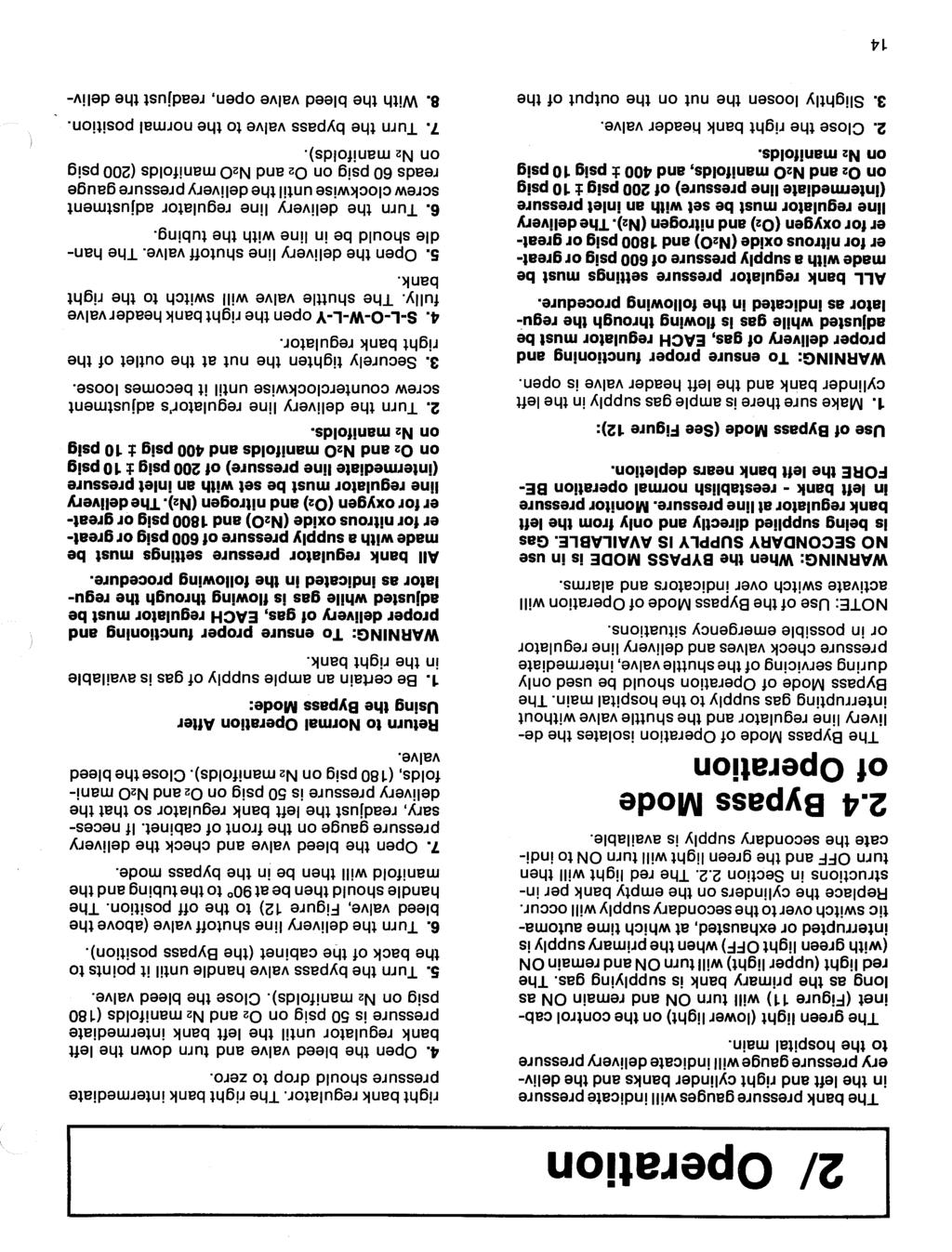
13 2/ Operation Red Light: Secondary supply in use - cylinders must be replaced on empty bank Green Light: Primary supply in use - secondary supply available Lett and Right Pressure Switches Left Bank Header Valve Shutoff Valve Right Bank Header Valve Figure and N20 Unimatic II: Header, Shutoff and Bypass Valves, Pressure Switches and Switch Over Indicators Header Valves and Shutoff Valve (Figure 8) The HEADER VALVE, upstream from the bank regulator, allows for gas shut off from the cylinder bank. The SHUTOFF VALVE between the delivery line regulator and the delivery pressure gauge is closed when the bypass mode is used (see page 14 for Bypass Mode Operation). These features permit servicing of various components between the header valve and shutoff valve without interrupting flow of gas. Bypass Valve (Figure 8) The BYPASS VALVE permits gas to be supplied directly from the left bank to the hospital delivery line during servicing of the shuttle valve, intermediate pressure check valves and delivery line regulator, or in possible emergency situations. When the bypass mode is in use the left bank regulator is adjusted to deliver gas at delivery pressure, the right bank header valve and the shutoff valve are closed, and the bypass valve is turned to the BYPASS position. Pressure Switches, Indicator Lights and Remote Alarms (Figures 8 and 9) The PRESSURE SWITCHES control the INDI- CATOR LIGHTS on the control cabinet front panel as well as remote alarms (when used). These indicators and alarms relate supply usage as either PRIMARY bank (normal operation) or switch over to the SECONDARY bank. Figure 9 shows an electrical wiring schematic of this switch over indicator circuit. Under normal operating conditions, the pressure in both primary and secondary intermediate 10
14 2/ Operation Red Light Red Blue Green Light Yellow Right Pressure Switch Relay NO ONC Black Red Green White Left Pressure Switch White NO ONC Blue Red Red Black V.A.C. Switch over signal from remote for closed circuit remote transformer alarms (for open circuit remote alarms use terminals 2 and 4) Figure 9. Wiring Schematic for Ohio Unimatic II Switch Over Alarm System lines will be 200 psig on 02 and N20 manifolds (400 psig on N2 manifolds) and the green light on the front panel will be ON. This condition is presented in the electrical schematic, Figure 9. The pressure switches are single pole double throw, set to switch at 155 psig on 02 and N20 manifolds (285 psig on N2 manifolds) as pressure drops. As the primary bank is depleted, its intermediate line pressure decreases; the pressure switch then closes, activates the relay, the green light goes OFF, and the red light goes ON to indicate that switch over to the secondary supply is about to occur. A signal is also transmitted to the remote alarm system. IMPORTANT: When the red indicator light and alarms first activate, they indicate that the gas supply from the primary bank is approaching depletion and that switch over is about to occur. They provide an indirect indication of switch over and signal that cylinders should be replaced on the depleted bank. Refer to Section 2.2, Cylinder Installation and Replacement. When full cylinders are installed and the header valve is opened, the pressure in the intermediate line is re-established at 200 psig on 02 and N20 manifolds (400 psig on N2 manifolds). This opens the pressure switch, deactivates the relay, and returns the indicator lights and alarms to normal operation with green light ON, red light OFF. The opposite bank now acts as the primary bank. When depleted of gas its pressure switch will also activate the red indicator light and remote alarms as previously described. 11
 208-5139-800 Hospital Main Shutoff Valve and Hi-Low Delivery Line Pressure Switch A HOSPITAL MAIN SHUTOFF VALVE should be installed immediately")
15 2/ Operation Figure 10. Hi-Low Delivery Line Pressure Switch (Accessory) Hospital Main Shutoff Valve and Hi-Low Delivery Line Pressure Switch A HOSPITAL MAIN SHUTOFF VALVE should be installed immediately downstream of the Unimatic II Manifold. Also, if a hi-low delivery line pressure alarm is used, the HI-LOW DELIVERY LINE PRESSURE SWITCH, should be installed downstream of the hospital main shutoff valve. Figure 10 shows a hi-low delivery line pressure switch available from Ohio as an accessory. 2.2 Cylinder Installation and Replacement WARNING: FIRE HAZARD. DO NOT permit smoking or any other source of ignition in area where the manifold is located or near relief valve vent outlet. Be certain all connections are free of dirt, grease and oil. These substances burn with great intensity in air enriched with oxygen or nitrous oxide. Attach gas supply cylinders to header pigtail connectors (Figure 11) as follows: 1. Check to be certain that the bypass valve is in the "Normal" position, header valves are open, and pigtails are securely tightened to header check valves. 2. Open and close each cylinder valve momentarily to blow foreign material from each cylinder valve opening. 3. Using the handle on the pigtail, smoothly pull the cylinder connection end of each pigtail to the cylinder valve and securely tighten each cylinder connection nut to the cylinder valve. CAUTION: Do NOT repeatedly bend, sharply bend or twist copper tubing as damage to the tubing may result. CAUTION: Each pigtail must be connected to a cylinder to prevent gas leaks. The header connection to the pigtail is equipped with a check valve; however, this valve is not leak free. If an inlet is not to be used, be certain the pigtail Is removed and the header inlet is securely sealed with a blind gland and nut. Refer to Illustrated Parts List, Page S-L-O-W-L-Y open valve on the cylinder nearest the manifold cabinet, and allow at least 60 seconds for heat of recompression to dissipate. 5. Then S-L-0-W-L-Y open the valves of the other cylinders. 6. Repeat steps 1-5, for the opposite bank. To Replace Empty Bank Cylinders: 1. Close all cylinder valves on bank to be replaced. NOTE: Switch over indicator lights activate before actual switch over takes place. The indicator lights activate at an intermediate line pressure of 155 psig on 02 and N20 manifolds or 285 psig on N2 manifolds. The shuttle valve switch over occurs at about a pressure of 100 psig on 02 and N20 manifolds or about 265 psig on N2 manifolds. Check the shuttle valve spindle - the side (left or right) from which the spindle rod protrudes the least indicates the bank which is supplying gas. Refer to Figures 5 and Slightly loosen the cylinder valve connection nuts to bleed off any residual pressure, then disconnect the empty cylinders. 3. Connect the full cylinders as indicated in Steps 1 through 5 of Section Gas Flow and Manifold Operation After the header valves are opened and the cylinders have been installed (per Sec. 2.2), check to be sure that the delivery line shutoff valve and the hospital main shutoff valve are open fully. Gas will now be supplied to the hospital main. 12
16 2/ Operation Red Light "ON" indicates secondary supply is being used and cylinders are to be replaced. Bypass Valve in "Normal" position Green Light "ON" indicates normal operation. Delivery Line Shutoff Valve Shuttle Valve Spindle Rod Open Left and Right Header Valves Cylinder Connection Nut - smoothly pull pigtail to cylinder valve and securely tighten connection nut. Header Check Valve Under cabinet Pigtail Stock No N N Side and Down Pigtail Stock No N Nz Be certain pigtails are tightened securely to header check valves Figure 11. Cylinder Installation and Manifold Operation 13
17
 - close bleed valve. 5. Turn Bypass Valve handle back of tocabinet.3.")
18 2/ Operation 1. Ample supply in left bank and Left Bank Header Valve OPEN. Delivery Line Regulator 2. Close Right Bank Header Valve. 4. Open bleed valve and turn down Left Bank Regulator until Left intermediate Pressure Gauge is 50 psi 02 and N20 (180 psi for N2) - close bleed valve. 5. Turn Bypass Valve handle back of tocabinet.3. Loosen Connection Nut slightly. 6. Turn Shutoff Valve to OFF. Figure 12. Bypass Mode Operation ery line regulator so that the delivery pressure gauge reads 50 psig on 02 and N20 manifolds (180 psig on N2 manifolds). Close the bleed valve. 9. Turn in the left bank regulator adjustment screw until the intermediate pressure is 250 psig for 02 and N20 manifolds on the left bank (450 psig for N2 manifolds). 10. Close the right bank header valve to obtain switch over and flow from the left bank. Then, open the bleed valve and readjust the left bank regulator so that the intermediate pressure is 200 psig ± 10 psig on 02 and N2 manifolds (400 psig ± 10 psig on N2 manifolds). Close the bleed valve and slowly open the right bank header valve. 11. The bank with the least gas* should be chosen as the PRIMARY SUPPLY side. Check the position of the shuttle valve spindle rod. The bank which is supplying gas will be indicated by the side of the shuttle valve on which the spindle rod protrudes the LEAST (See Figure 5). If this is the fullest bank* turn the corresponding header valve OFF until the shuttle valve switches. If gas is not being used, the bleed valve may have to be opened until intermediate line pressure drops enough to cause switch over. After switch over, close the bleed valve and slowly open the header valve. * NOTE: For 02 and N2 manifolds the bank pressure gauge with lowest reading will indicate the bank having least gas. Nitrous oxide, however, is in liquid form in the cylinders (at above 800 psig). Therefore both bank pressure gauges may indicate the same pressure although the liquid level in one bank may be lower. Under such conditions it is not practical to determine which bank is fullest; one bank must be chosen as the PRIMARY SUPPLY and the other as SECONDARY SUPPLY. 15

19 3/ Maintenance 3.1 General WARNING: The person performing service on the manifold is responsible for obtaining permission from the hospital administration prior to performing any check-out or repairs of the manifold. WARNING: Never oil or grease oxygen or nitrous oxide equipment unless a lubricant that is made and approved for this type of service (such as Vac Kote* Stock No ) is used or a certain type of lubricant is specified for a particular part of a unit. Oils and greases oxidize readily and, in the presence of oxygen, will burn violently. WARNING: Use extreme care, when working with high pressure oxygen components and systems, to keep hands, tools and work environment free of oils which are highly combustible in the presence of high pressure oxygen. WARNING: The left and right banks must have sufficient gas volume to perform any test and supply hospital demand. WARNING: Only one header valve may be turned off while the manifold is supplying gas to the hospital. After performing checks or making repairs return header valves to the open position. CAUTION: Repair of the Unimatic II 02, N2 and N20 manifolds should not be undertaken until all required tools, test equipment, and special materials that may be required are available. Use of Teflon Tape Teflon tape may be used on all pipe threads; however, it should not be used on compression fittings. See Figure 13, How to Apply Teflon Tape. Testing piping connections for leaks Leak test piping connections after any repair or replacement procedure. Perform the leak test with Snoop*, a commercial leak test solution approved by the Ohio Medical Products Service Department. A soap solution of one teaspoon Ivory Liquid detergent per gallon of water may also be used. The leak test solution should be applied to the piping connection under test. Avoid getting the leak test solution on any electrical components. The formation of bubbles indicates a leak. The leaks should be eliminated by retightening or replacing connections and tubing, then retest the connections. NOTE: Clean surface of connection and components after testing - dry soap may be combustible in the presence of oxygen or nitrous oxide. Nitrous Oxide Manifold repair and test procedure information WARNING: Nitrous oxide is in liquid form in the cylinders (at above 800 psig). Therefore, both bank pressure gauges may indicate the same pressure although the liquid level in one bank may be lower. The possibility of a bank depletion occuring while service is being performed should be avoided. The installation of one or two full Nitrous Oxide cylinders for the duration of the repair or test procedure will prevent this. The Mode of Operation for Service. Table 2 on Page 17, Mode of Operation for Service, provides a guide to servicing the manifold. Determine from the table which bank needs to be in operation for service to a particular item. WARNING: FIRE HAZARD. DO NOT permit smoking or any other source of ignition in area where the manifold is located or near relief valve vent outlet. Be certain all connections are free of dirt, grease and oil. These substances burn with great intensity in air enriched with oxygen or nitrous oxide. *Vac.Kote is a registered trademark of the Ball Corporation. A one ounce supply of Vac Kote is available from Ohio Medical Products, Stock No *Snoop is a tradename of the Nupro Company (2 oz. supply , 1 gal. supply ). *Ivory Liquid is a registered trademark of Procter & Gamble. 16
20 3/ Maintenance 1. Wrap tape clockwise, starting one thread up, as viewed from end of male fitting. 2. Apply enough pressure so tape lust starts to follow contours of threads. 3. Wrap two layers of tape thick. Figure 13. How to Apply Teflon Tape Table 2. Mode of Operation for Service Left Bank Operation: permits service including replacement, of the following Right Bank items with the Right Header Valve closed: Right Bank Pressure Gauge R i g h t Intermediate Pressure Gauge Right Bank Regulator R i g h t Pressure Switch Right Relief Valve Right Bank Operation: permits service including replacement, of the following Left Bank items with the Left Header Valve closed: Left Bank Pressure Gauge Left Bank Regulator Left Relief Valve Left Intermediate Pressure Gauge Left Pressure Switch Bypass Mode of Operation: permits service including replacement, of the following: Shuttle Valve Check Valves (Intermediate Pressure) Delivery Line Regulator The manifold will have to be shut down to service or replace the following: Shutoff Valve D e l i v e r y Line Relief Valve Delivery Pressure Gauge B y p a s s Valve Bleed Valve NOTE: The spindle position on the shuttle valve will determine which bank is supplying gas to the manifold. Check the shuttle valve spindle - the side (left or right) from which the spindle rod protrudes the least indicates the bank which is supplying gas. 17

21 3/ Maintenance 3.2 Regulator Adjustment WARNING: To ensure proper functioning and proper delivery of gas, EACH regulator must be adjusted while gas is flowing through the regulator as indicated in the following procedure. All bank regulator pressure settings must be made with a supply pressure of 600 psig or greater for nitrous oxide (N20) and 1800 psig or greater for oxygen (02) and nitrogen (N2). The delivery line regulator must be set with an inlet pressure (intermediate line pressure) of 200 psig ± 10 psig on 02 and N20 manifolds or 400 psig ± 10 psig on N2 manifolds. A. Bank Regulators (See Figure 14) WARNING: To ensure a continuous supply of gas during regulator adjustment, be certain ample supply of gas is available in both cylinder banks and NEVER close a header valve unless the opposite bank header valve is open. NOTE: During this procedure, switch over indicator lamps and alarms will activate. 1. Check to be sure the cylinder pressure to the bank regulator being adjusted is 600 psig or greater for N20, 1800 psig or greater for 02 and N2. 2. Slowly open the header valve on the bank being adjusted. 3. If necessary, the adjustment screw of the regulator to be adjusted should be turned clockwise until at least 200 psig (400 psig on N2 manifolds) is indicated on the intermediate pressure gauge (inside of cabinet). 4. Close the header valve on the opposite bank (away from the regulator being adjusted). This will ensure shuttle valve switch over and flow through the regulator being adjusted. 5. Open the bleed valve. Allow the shuttle valve to switch over so that gas is being supplied from the bank regulator being adjusted. NOTE: The shuttle valve is supplying gas from the bank corresponding to the side of the shuttle valve from which the spindle rod protrudes the least; see Figures 5, 6 and With the bleed valve open, turn the regulator adjustment screw until the corresponding pressure gauge (inside cabinet) indicates 200 psig ± 10 psig on 02 and N20 manifolds, 400 psig ± 10 psig on N2 manifolds. 7. Close the bleed valve and slowly open the header valve on the opposite bank. NOTE: The intermediate pressure gauge may indicate a slightly greater pressure (up to 215 psig on 02 and N20 manifolds, up to 425 psig on N2 manifolds) when gas is not flowing through the regulator. Such an increase is normal. 8. The bank with the least gas* should be chosen as the PRIMARY SUPPLY side. Check the position of the shuttle valve spindle rod. If the fullest bank is feeding the system, turn the corresponding header valve off until the shuttle valve switches. If gas is not being used the bleed valve may have to be opened until intermediate line pressure drops enough to cause switch over. After switch over, close the bleed valve and slowly open the header valve. NOTE: For 02 and N2 manifolds the bank pressure gauge with lowest reading will indicate the bank having least gas. Nitrous oxide, however, is in liquid form in the cylinders (at above 800 psig). Therefore both bank pressure gauges may indicate the same pressure although the liquid level in one bank may be lower. Under such conditions it is not practical to determine which bank is fullest; one bank must be chosen as the PRIMARY SUPPLY and the other as the SECONDARY SUP- PLY. 18
 1.")
22 3/ Maintenance Delivery line Regulator Adjustment Screw Left and Right Intermediate Pressure Left Bank Header Valve Right Bank Header Valve Left and Right Bank Regulator Adjustment Screws Bleed Valve Position of Shuttle Valve Spindle indicating bank supplying gas. Figure 14. Regulator Adjustment 02 and N20 Unimatic II B. Delivery Line Regulator (See Fig. 14) 1. Check to be sure the delivery line regulator inlet pressure (as shown on the intermediate pressure gauge of the bank supplying gas) is 200 psig ± 10 psig on 02 and N2 manifolds or 400 psig ± 10 psig on N2 manifolds. If not, adjust the bank regulator as outlined in 3.2A. 2. Open the bleed valve to obtain flow through the regulator. 3. Turn the delivery line regulator adjustment screw until the delivery pressure gauge on the front panel of the cabinet indicates 50 psig on 02 and N20 manifolds, 180 psig on N2 manifolds. 4. Close the bleed valve. NOTE: The delivery pressure gauge may indicate a slightly greater pressure (up to 58 psig on 02 and N20 manifolds or up to 192 psig on N2 manifolds) when gas is not flowing through the regulator. Such an increase is normal. 19

23 3/ Maintenance 3.3 Pressure Switch Checking and Adjustment (Figure 15) NOTE: During the pressure switch checking and adjustment procedure, switch over indicators and alarms will activate. WARNING: To ensure flow of gas to the delivery line during the pressure switch checking and adjustment procedure, BE CERTAIN sufficient supply is available in both cylinder banks. During the checking and adjustment procedure, bank regulator pressure settings must be changed and readjusted as necessary. To ensure proper flow to the delivery line, the bank regulator adjustment must be made with an inlet (cylinder) pressure of 1800 psig or greater for 02 and N2, and 600 psig or greater for N Be certain the header valve and cylinder valves on each bank are open and the outlet pressure of each bank regulator is at 200 psig t 10 psig on 02 and N20 manifolds, 400 psig t 10 psig on N2manifolds. If necessary, adjust bank regulator as instructed in Section 3.3A, Page The bank being serviced must be the bank which is supplying gas. If the opposite bank is supplying gas (as indicated by the position of the shuttle valve spindle rod - see Figures 5 and 6, Pages 7 and 8), close the header valve on this bank and open the bleed valve. This will cause the shuttle valve to switch over and the bank to be serviced will be supplying gas. Slowly reopen the header valve. 3. To Check Pressure Switch Setting on Bank Supplying Gas: CAUTION: The pressure at which the pressure switch is set to indicate switch over must be checked as pressure in the intermediate line drops. Open the bleed valve and slowly turn the bank regulator adjustment screw counterclockwise - this will cause the intermediate line pressure of this bank to drop. Observe the intermediate line pressure gauge and the switch over indicator lights as the pressure drops. The pressure switch must activate - red light to on, green light off - when the pressure gauge indicator drops to between 160 psig and 150 psig on 02 and N20 manifolds, or between 295 psig and 275 psig on N2 manifolds. In Adjustment The switch is properly set if it activates within the previously described range. With the bleed valve open, turn the bank regulator adjustment screw clockwise until the intermediate pressure gauge is at 200 psig t 10 psig on 02 and N2 manifolds, or 400 psig t 10 psig on N2manifolds. Close the bleed valve. Out of Adjustment A. The switch is set too high if it activates red light ON - green light OFF at a pressure above 160 psig on 02 and N20 manifolds, or above 360 psig on N2 manifolds. B. The switch is set too low if it activates at a pressure below 150 psig on 02 and N20 manifolds, or below 340 psig on N2 manifolds. Adjust the pressure switch as instructed in Step To Adjust Pressure Switch on Bank Supplying Gas: A. Switch Set Too High (as indicated in Step 3) a. With the bleed valve open, turn the bank regulator adjustment screw to set the outlet pressure (on the intermediate pressure gauge) between 155 psig and 160 psig on 02 and N20 manifolds, or between 285 psig and 295 psig on N2 manifolds - the red indicator light should be on. Close the bleed valve. b. Turn the knurled nut of the pressure switch to the left until the red light turns off - green light on. The pressure within the intermediate line may make it difficult to turn the knurled nut - if so, use a flat head screwdriver as a lever against the side of the switch with blade on knurled nut and carefully work the nut to the left as illustrated in Figure 15. NOTE: Nitrogen pressure switches have a IA" hex adjustment nut (not a knurled nut). c. Turn the bank regulator adjustment screw clockwise until the intermediate pressure reaches 180 psig to 200 psig on 02 and N20 manifolds (380 psig to 400 psig on N2manifolds) -green light should be ON. Then, open the bleed valve and slowly turn the regulator adjustment screw counterclockwise until the red light turns ON - green light turns OFF. CAUTION: The pressure at which the pressure switch is set to indicate switchover must be checked as pressure in the intermediate line drops. Check the intermediate pressure - it must be between 150 psig and 160 psig for 02 and N20 20
24 3/ Maintenance Left intermediate Pressure Right intermediate Pressure Left Header Left Bank Valve Regulator Adjustment Screw Bleed Valve S h u t t l e Valve R i g h t Header behind tubing S p i n d l e V a l v e Right Bank Regulator Adjustment Screw Turn clockwise to increase intermediate pressure - counterclockwise to decrease intermediate pressure. Knurled Adjustment Nut 1/4" Hex Adjustment Nut U s e 1/4" wrench to adjust Oxygen and Nitrous Oxide Pressure Switches Use flat blade screwdriver to turn knurled nut to left to lower pressure setting - to right to raise pressure setting. Nitrogen Pressure Switches Figure 15. Pressure Switch Checking and Adjustment 21

25 3/ Maintenance manifolds or between 275 psig and 295 psig for N2 manifolds. If it is not within this range, readjust the switch slightly and check setting by raising and lowering the intermediate pressure as described earlier. Repeat as necessary until proper adjustment is made. d. Perform a final check of the pressure setting by again turning the bank regulator adjustment screw to raise and then (with bleed valve open) lower the intermediate pressure. e. With the bleed valve open, readjust the bank regulator (intermediate pressure) to 200 psig 10 psig on 02 and N20 manifolds, or 400 psig 10 psig on N2 manifolds. B. Switch Set Too Low (as indicated in Step 3) a. With the bleed valve open, turn the bank regulator adjustment screw to set the outlet pressure (on intermediate pressure gauge) betwen 150 psig and 155 psig on 02 and N20 manifolds or between 275 psig and 285 psig on N2 manifolds - the green indicator light should be ON. Close the bleed valve. b. Turn the knurled nut of the pressure switch to the right until the green light turns OFF and the red light turns ON. The pressure within the intermediate line may make it difficult to turn the knurled nut, if so, use a flat head screwdriver as a lever against the side of the switch with the blade on the knurled nut and carefully work the nut to the right. NOTE: Nitrogen pressure switches have a 1/4" hex adjustment nut (not a knurled nut). c. Turn the bank regulator adjustment screw clockwise until the intermediate pressure reaches 180 psig to 200 psig on 02 and N20 manifolds (380 psig to 400 psig for N2 manifolds) - green light should be on. Then, open the bleed valve and slowly turn the regulator adjustment screw counterclockwise until the red light turns screw counterclockwise until the red light turns ON and the green light turns OFF. CAUTION: The pressure at which the pressure switch is set to indicate switch over must be checked as pressure in the intermediate line drops. Check the intermediate pressure - it must be between 150 psig and 160 psig on 02 and N20 manifolds or between 275 psig and 295 psig on N2 manifolds. If it is not within this range, readjust the switch slightly and check setting by raising and lowering the intermediate pressure as described above. Repeat as necessary until proper adjustment is made. d. Perform a final check of the pressure setting by again turning the bank regulator adjustment screw to raise and then (with bleed valve open) lower the intermediate pressure. e. With bleed valve open, readjust the bank regulator (intermediate pressure) to 200 psig 10 psig on 02and N20 manifolds, 0r400 psig ± 10 psig on N2 manifolds. 3.4 Switch Over Indicator Circuit Check-Out WARNING: The left and right banks must have sufficient gas volume to perform any test and supply hospital demand. WARNING: Only one header valve may be turned off while the manifold is supplying gas to the hospital. After performing checks or making repairs return header valves to the open position. The switch over indicator circuit may be tested by simulating left and right bank pressure depletion. See Section 2.1 for the theory of operation. Check Out Procedure: Normal Manifold Pressure Settings Nitrogen Manifold Intermediate Pressure Switches psig Bank Regulators psig Delivery Line Regulator psig Oxygen and Nitrous Oxide Manifolds Intermediate Pressure Switches Bank Regulators Delivery line Regulator psig 200 psig 50 psig NOTE: See sections 3.2 and 3.3 for proper adjustment procedures. 1. The manifold is in a normal operating condition - the pressure in both primary and secondary intermediate lines is 200 psig on 02 and N20 manifolds (400 psig on N2 manifolds) and the green light on the front panel is on. This condition is presented in the electrical schematic Figure Both header valves are in the open position. 3. Determine which bank is supplying gas to the delivery line. The spindle position on the shuttle valve will determine this. See Figure 6b. Check the shuttle valve spindle - the side (left or right) from which the spindle rod protrudes the least indicates the bank which is supplying gas. Refer to Figure 5. 22
26 3/ Maintenance Red Light Red Blue 3 0 Green Light Yellow Right Pressure Switch Relay NO 0 NC Black Red White Green White AN NO 0 NC Left Pressure Switch Blue Red Red Black 1 2\ V.A.C. Switch over from remote signal for closed circuit transformer remote alarms (for open circuit remote alarms use terminals 2 and 4) 4. S-L-O-W-L-Y close the header valve on the bank supplying gas to the delivery line. This action simulates the depletion of the primary bank. NOTE: If the shuttle valve does not shuttle you may have closed the wrong header valve. Slowly reopen the header valve closed previously and slowly close the other header valve. NOTE: The bleed valve may have to be opened to simulate hospital demand. The following activities should then take place. a. Bank pressure decreases. b. Intermediate line pressure decreases. c. The pressure switch closes. d. The relay is activated. e. The green light goes OFF. f. The red light goes ON. g. Remote alarms are activated if present. h. The shuttle valve shuttles. The troubleshooting information of section 3.5 will be of assistance in determining malfunctions in the switch over indicator circuit. 5. S-L-O-W-L-Y reopen the header valve closed previously. The following activities should then take place. a. Bank pressure is re-established. b. Intermediate line pressure is re-established at Figure 16. Wiring Schematic for Ohio Unimatic II Switch Over Alarm System 200 psig on 02 and N20 manifolds (400 psig on N2 manifolds). c. The pressure switch opens. d. The relay is deactivated. e. The red light turns off. f. The green light turns on. g. Remote alarms are deactivated if present. The manifold is now operating from the opposite bank. The bank with the least gas* should be chosen as the PRIMARY SUPPLY side. Check the position of the shuttle valve spindle rod. The bank which is supplying gas will be indicated by the side of the shuttle valve on which the spindle rod protrudes the least (See Figure 5). If this is the fullest bank* turn the corresponding header valve OFF until the shuttle valve switches. If gas is not being used, the bleed valve may have to be opened until intermediate line pressure drops enough to cause switch over. After switch over, close the bleed valve and slowly open the header valve. *NOTE: For 02 and N2 manifolds the bank pressure gauge with lowest reading will indicate the bank having least gas. Nitrous oxide, however, is in liquid form in the cylinders (at above 800 psig). Therefore both bank pressure gauges may indicate the same pressure although the liquid level in one bank may be lower. Under such conditions it is not practical to determine which bank is fullest; one bank must be chosen as the PRIMARY SUPPLY and the other as SECONDARY SUPPLY. 23
27 3/ Maintenance 3.5 Switch Over Indicator Circuit- Troubleshooting Information See Section 2.1 for a theory of operation of the switch over alarm system. See Section 3.4 for Switch Over Indicator Circuit Check-Out and section 3.7 for Switch Over Indicator Circuit repairs. The troubleshooting table for the switch over alarm system is shown in Table 3. The table is a guide to possible solutions for repairs to the switch over indicator circuit. Multiple component failures are not covered in the table. The remote alarms vary for each installation. Switch over signals are taken from terminals 2 and 4 or 2 and 5 (See Figure 16). Terminals 2 and 4 provide a switch over signal for open circuit remote alarms. A failure in the switch over alarm circuit may not cause a change in the open circuit remote alarm. Terminals 2 and 5 provide a switch over signal for closed circuit alarms. A failure in the switch over alarm circuit will cause a change in the closed circuit remote alarm. Maintenance is required when the indicator circuit display differs from the remote alarm display. NOTE: The closed circuit remote alarm system provides the best assurance of correct operation of the manifold switch over alarm circuits. Table 3. Troubleshooting Information Switch Over Alarm System Left Right Possible Red Green intermediate intermediate component Condition Lamp Lamp Pressure Pressure failures 1. OFF OFF LOW LOW 1, 2 2. OFF OFF LOW HIGH 1, 2 3. OFF OFF HIGH LOW 1, 2 4. OFF OFF HIGH HIGH 1, 3, 4 5. OFF ON LOW LOW 6 6. OFF ON LOW HIGH 6 7. OFF ON HIGH LOW 5, 6, 7 8. OFF ON HIGH HIGH Normal, 5, 6, 7 9. ON OFF LOW LOW Normal, 4, 6, ON OFF LOW HIGH Normal, 4, 6, ON OFF HIGH LOW Normal, 4, 6, ON OFF HIGH HIGH ON ON LOW LOW ON ON LOW HIGH ON ON HIGH LOW ON ON HIGH HIGH 5 NOTE: The left and right intermediate pressure gauges are assumed to be accurate for this table. An indication of intermediate gas pressure presence may be verified by reading the left and right bank pressure gauges. List of Possible Component Failures 1. Power Off - check transformer and supply voltage. 2. Red light out - replace lamp. See Page Green light out - replace lamp. See Page Relay (4-5 OPEN) - replace relay. See Page Relay (Open coil) - replace relay. See Page Left Intermediate Pressure switch in need of adjustment or defective - adjust or replace as required. See Pages 20 and Right Intermediate Pressure switch in need of adjustment or defective - adjust or replace as required. See Pages 20 and Incorrect lens position or improper wiring. See Page

28 3/ Maintenance How to use the troubleshooting table. Compare the actual condition of the manifold with the possible condition listed in Table 3. The right side of the table lists the possible component failures by number, refer to the list of possible component failures for explanations. Conditions 8,9, 10 and 11 are normal conditions; however, the possible component failures listed will make the manifold appear to be in a normal state of operation when in fact there may be a problem with a component. The problem in some cases, may not show up until the secondary bank pressure is depleted if an open circuit remote alarm is in use. 3.6 Pressure Switch Electrical Check Out The troubleshooting information of section 3.5 will be of assistance in determining possible pressure switch malfunctions. The pressure switch may be tested with an ohmmeter to verify proper operation. Ohmmeter check out procedure: 1. Refer to Figure 31 for the wiring diagram. 2. Unplug the switch in question. NOTE: Unplugged switches produce a green light condition on the manifold but also activate closed circuit remote alarms. The switches should be replugged securely after the ohmmeter test. 3. Insert the ohmmeter probes in the back of the connector. See Figure 16 for electrical wiring schematic. Check the continuity from common to normally open and common to normally closed. Activate the switch manually by using a small blade screwdriver. NOTE: Pressure switches are in the normally open position when pressure is applied. 4. If the switch is working normally replug the switch into the circuit. See Section 3.19 to replace a defective pressure switch. See section 3.3 for Pressure Switch Checking and Adjustment. Figure 17. Lampholder Replacement 3.7 Switch Over Indicator Circuit Repairs An electrical schematic of the switch over indicator circuit is shown in Figure 16. The switch over indicator circuit wiring diagram with replacement parts is given in Figure 31 of Section 4, Illustrated Parts List. Lamp Replacement Lamps for the indicator lights are set deep in the lampholders. To remove these lamps, use a short (2") length of 1/2" I.D., thin walled rubber tubingpush tubing over end of lamp and unscrew lamp from socket. WARNING: Do NOT interchange indicator light lenses - upper light lens is RED, lower light lens Is GREEN. Lampholder Replacement WARNING: Disconnect electricity to the unit beforeattempting anyelectricall-comporient repairs. After power has been disconnected use an ohmmeter to check continuity of the portion of the circuit in question. The primary and secondary supply lampholders are easily replaced. Refer to Figures 17 and 31 for proper assembly and electrical connections. 25

29 3/ Maintenance Relay Terminal Block Figure 18. Relay Replacement Relay Replacement WARNING: Disconnect electricity to the unit before attempting any electrical component repairs. The troubleshooting information of section 3.5 will be of assistance in determining relay malfunctions. Relay Replacement Procedure: 1. Refer to Figure 31, page 41 for a wiring diagram and Figure 18 for a photo. 2. Disconnect the electrical power. 3. Verify that the wires on the relay agree with the wiring diagram. Label the wires if necessary. NOTE: The two blue wires on the relay are electrically the same point. 4. Remove the wires from the relay by pulling them off by hand or with a pliers. 5. Remove the two mounting screws and the relay. 6. Mount the replacement relay with terminals 3 and 4 at the top. 7. Reconnect the wires to the relay. Verify that the wires on the relay agree with the wiring diagram. 8. Reconnect the electrical power. 9. Perform a check out of the switch over indicator circuit. See Section
30 3/ Maintenance 3.8 Pneumatic Switch Over Circuit Check-Out WARNING: The left and right banks must have sufficient gas volume to perform any test and supply hospital demand. WARNING: Only one header valve may be turned off while the manifold is supplying gas to the hospital. After performing checks or making repairs return the header valves to the open position. The pneumatic switch over circuit may be tested by simulating left and right bank pressure depletion. See Section 2.1 for Theory of Operation. Check-Out Procedure: Normal Manifold Pressure Settings Nitrogen Manifold Intermediate Pressure Switches Bank Regulators Delivery Line Regulator psig 400 psig 180 psig Oxygen and Nitrous Oxide Manifold Intermediate Pressure Switches psig Bank Regulators psig Delivery Line Regulator 5 0 psig NOTE: See Sections 3.2 and 3.3 for proper adjustment procedures. 1. The manifold is in a normal operating condition - the pressure in both primary and secondary intermediate lines is 200 psig on 02 and N20 manifolds (400 psig on N2 manifolds). 2. Both header valves are in the open position. 3. Determine which bank is supplying gas to the delivery line. The spindle position on the shuttle valve will determine this. See Figure 6b. Check the shuttle valve spindle - the side (left or right) from which the spindle rod protrudes the least indicates the bank which is suppying gas. Refer to Figures 5 and S-L-O-W-L-Y close the header valve on the bank supplying gas to the delivery line. This action simulates the depletion of the primary bank. NOTE: If the shuttle valve does not shuttle you may have closed the wrong header valve. Slowly, reopen the header valve previously closed and slowly close the other header valve. NOTE: The bleed valve may have to be opened to simulate hospital demand. The following activities should then take place. a. Bank pressure decreases. b. Intermediate line pressure decreases. c. The pressure switch closes. d. Remote alarms are activated if present. e. The shuttle valve shuttles. Check for leaks in the manifold. The shuttle valve is allowed to leak through the vent valve at a rate of 18cc/minute and through the end caps at a rate of 4cc/minute each with a pressure of 200 psig applied. The troubleshooting information of the pneumatic circuit, Section 3.9, Page 28 will assist you in determining any malfunctions in the pneumatic switch over circuit. 5. S-L-O-W-L-Y reopen the header valve. The following activities should then take place: a. Bank pressure is reestablished. b. Intermediate line pressure is reestablished at 200 psig (400 psig for N2 manifolds). c. The pressure switch opens. d. Remote alarms are deactivated if present. The manifold is now operating from the opposite bank. The manifold should always be operating from the bank with the lowest capacity. The manifold can be returned to the original bank by slowly closing the opposite header valve. This causes the manifold to shuttle to the original bank. Slowly reopen the header valve returning the manifold to its original state. After performing checks or making repairs always return header valves to the open position. 27
31 3/ Maintenance 3.9 Pneumatic Circuit-Troubleshooting Information Table 4. Condition P o s s i b l e Cause S o l u t i o n Pressure on Intermediate B a n k regulator seat R e p a i r or replace bank pressure gauge rises i s defective, r e g u l a t o r. slowly. Press on delivery line D e l i v e r y line regulator R e p a i r or replace gauge rises slowly, s e a t is defective. r e g u l a t o r. Intermediate line relief B a n k regulator is out of R e a d j u s t, repair or valve leaks. a d j u s t m e n t or defective, r e p l a c e regulator. Relief valve is defective. R e p l a c e relief valve. Delivery line relief D e l i v e r y line regulator is R e a d j u s t, repair or valve leaks. o u t of adjustment or r e p l a c e regulator. defective. Relief valve R e p l a c e relief valve. is defective. Shuttle valve leaks. C h e c k valve is defective. R e p l a c e check valve. Teflon seal is defective. R e p a i r or replace shuttle Shuttle spool is defective. v a l v e. Bleed valve leaks. B l e e d valve is defective. R e p l a c e bleed valve. Pressure switch P r e s s u r e switch is R e p l a c e pressure switch. activation is erratic. d e f e c t i v e. Pressure gauge leaks, G a u g e is defective. R e p l a c e gauge. does not return to zero, or readings are inconsistent. 28

32 3/ Maintenance Inlet Compression Nut Outlet Compression Nut Figure 19. Oxygen and Nitrous Oxide Bank Regulator Replacement 3.10 Oxygen, Nitrous Oxide and Nitrogen Bank Regulator Replacement WARNING: Do not use oil or oilbearing materials on or near regulators. Oils and greases oxidize readily and, In the presence of oxygen, they will burn violently. Nonmetallic parts of regulators must be discarded permanently If contaminated with oil or grease. DO NOT LUBRICATE REGU- LATOR PARTS. Removal Procedure: (See Figures 19 and 20) 1. Refer to Table I, Page 4, Mode of Operation for Service to determine which bank must be in operation. 2. Slowly close the header valve on the side of the manifold requiring service. 3. While holding the connection fitting, slowly turn the regulator outlet compression nut counterclockwise to release any pressure still present in the line. Then turn the outlet compression nut off completely. 4. While holding the regulator, turn the regulator inlet compression nut counterclockwise and remove the regulator. Refer to Section 4 for bank regulator repair kits. Installation Procedure: NOTE: Transfer relief valve for oxygen and nitrous oxide regulators if a new regulator is used. 1. Place the regulator in position and start both the inlet and outlet compression nuts by turning them clockwise by hand. 2. While holding the regulator, tighten the regulator inlet compression nut. (Do not overtighten.) 3. While holding the connection fitting of the regulator, tighten the outlet compression nut. (Do not overtighten). 4. The bank with the least gas* should be chosen as the PRIMARY SUPPLY side. Check the position of the shuttle valve spindle rod. The bank which is supplying gas will be indicated by the side of the shuttle valve on which the spindle rod protrudes the LEAST (See Figure 5). If this is the fullest bank* turn the corresponding header valve OFF until the shuttle valve switches. If gas is not being used, the bleed valve may have to be opened until intermediate line pressure drops enough to cause switch over. After switch over, close the bleed valve and slowly open the header valve. *NOTE: For 02 and N2 manifolds the bank pressure gauge with lowest reading will indicate the bank having least gas. Nitrous oxide, however, is in liquid form in the cylinders (at above 800 psig). Therefore both bank pressure gauges may indicate the same pressure although the liquid level in one bank may be lower. Under such con- 29

33 3/ Maintenance Inlet Compression Nut Outlet Compression Nut Figure 20. Nitrogen Bank Regulator Replacement ditions it is not practical to determine which bank is fullest; one bank must be chosen as the PRI- MARY SUPPLY and the other as SECONDARY SUPPLY. 5. Test the piping connections for leaks Oxygen, Nitrous Oxide and Nitrogen Delivery Line Regulator Replacement WARNING: Do not use oil or olibearing materials on or near regulators. Oils and greases oxidize readily and, In the presence of oxygen, they will burn violently. Nonmetallic parts of regulators must be discarded permanently if contaminated with oil or grease. DO NOT LUBRICATE REGU- LATOR PARTS. Removal Procedure (See Figures 21 and 22): 1. Refer to Section 2.4, Page 14, Bypass Mode of Operation and perform steps 1 through 7 of the Use of Bypass Mode. After the manifold is in the bypass mode of operation the replacement procedure may be started. 2. The top cover of the manifold may be removed for easier access. 3. While holding the connection fitting of the regulator, slowly turn the regulator outlet compression nut counterclockwise to release any pressure still present in the line. Turn the outlet connection nut off completely. 4. While holding the regulator, turn the regulator inlet compression nut counterclockwise and remove the regulator. Refer to Section 4 for delivery line regulator repair kits. Installation Procedure: 1. Place the regulator in position and start both the inlet and outlet compression nuts by turning them clockwise by hand. 2. While holding the regulator, tighten the regulator inlet compression nut. (Do not overtighten.) 3. While holding the connection fitting of the regulator, tighten the outlet compression nut. (Do not overtighten.) 4. Refer to Section 2.4, Page 14, Bypass Mode of Operation and perform steps 1 through 11 of the Return to Normal Operation after Using the Bypass Mode. 5. Test the piping connections for leaks. 30

34 3/ Maintenance Outlet Compression Nut Inlet Compression Nut Figure 21. Oxygen and Nitrous Oxide Delivery Line Regulator Replacement Outlet Compression Nut Inlet Compression Nut Figure 22. Nitrogen Delivery Line Regulator Replacement 31
: NOTE: The shuttle valve may be serviced only after the manifold is in the bypass mode of operation. 1. Refer to Section 2.")
35 3/ Maintenance Inlet Connection Fitting Inlet Compression Nut Outlet Lines Inlet Compression Nut Inlet Connection Fitting Figure 23. Shuttle Valve Replacement 3.12 Shuttle Valve Replacement Removal Procedure (See Figure 23): NOTE: The shuttle valve may be serviced only after the manifold is in the bypass mode of operation. 1. Refer to Section 2.4, Page 14, Bypass Mode Operation and perform steps 1 through 7 of the Use of Bypass Mode. 2. The bottom cover of the manifold may be removed for easier access. 3. While holding the shuttle valve inlet connection fitting, slowly turn the inlet compression nut counterclockwise to release any pressure still present in the line, then turn the nut off completely. 4. The other shuttle valve inlet connection nut may be removed in the same manner as step While holding the shuttle valve outlet connection fitting, slowly turn the outlet compression nut counterclockwise to release any pressure still present in the line, then turn the nut off completely. 6. The other shuttle valve outlet connection nut may be removed in the same manner as step The shuttle valve may now be removed. Installation Procedure: 1. Place the shuttle valve in position and start the outlet connection nuts by turning them clockwise by hand. 2. Start the inlet connection nuts in the same manner as step While holding the shuttle valve outlet connection fitting, tighten the outlet connection nut. (Do not overtighten.) 4. The other shuttle valve outlet connection nut may be tightened in the same manner as step While holding the shuttle valve inlet connection fitting, tighten the inlet connection nut. (Do not overtighten.) 6. The other shuttle valve inlet connection nut may be tightened in the same manner as step Refer to Section 2.4, Page 14, Bypass Mode of Operation and perform steps 1 through 11 of the Return to Normal Operation After Using the Bypass Mode. 8. Test the piping connections for leaks. 32

36 3/ Maintenance Inlet Fitting Inlet Fitting Compression Nut Compression Nut Right intermediate Pressure Check Valve 3.13 Intermediate Pressure Check Valve Replacement Determine which check valve is the possible cause of a gas leak through the shuttle valve vent. Refer to Figure 6b, Page 8. When the left bank is supplying gas to the manifold and a leak is present at the shuttle valve vent, the right check valve could be the probable cause. Replace the right check valve. When the right bank is supplying gas to the manifold and a leak is present at the shuttle valve vent, the left check valve could be the probable cause. Replace the left check valve. Removal Procedure: (See Figure 25) NOTE: The Check Valve(s) may be serviced only after the manifold is in the Bypass Mode of Operation. 1. Refer to Section 2.4, Page 14, Bypass Mode of Left intermediate Pressure Check Valve Figure 24. Check Valve Replacement Operation, and perform steps 1 through 7, of the Use of Bypass Mode. 2. The top cover of the manifold may be removed for easier access. 3. While holding the check valve, turn the compression nut counterclockwise and remove the copper tubing. 4. While holding the inlet fitting, turn the check valve counterclockwise and remove it. Installation Procedure: 1. Wrap 2 layers of teflon tape on the inlet fitting. 2. Install the replacement check valve. 3. While holding the inlet fitting, turn the check valve clockwise to tighten. Do not overtighten. 4. While holding the check valve, turn the compression nut clockwise and tighten the copper tubing. 5. Test the piping connections for leaks. 33

37 3/ Maintenance Right Bank Relief Valve Left Bank Relief Valve NOTE: Nitrogen Unimatic II / Intermediate Relief Valves have a slightly different configuration. Figure 25. Intermediate Line Relief Valve Replacement 3.14 Intermediate Line Relief Valve Test (See Figure 25) To prevent damage to the delivery line regulator and the intermediate line pressure gauge, the relief valves on 02 and N20 manifolds are set at 250 psig, while the N2 relief valves are set at 475 psig. The relief valve will also prevent a premature switch over of the shuttle valve should a bank regulator seat leak occur. The following is a test for proper operation of the intermediate relief valve: NOTE: The relief valve being tested must be in the circuit supplying gas to the hospital. 1. Slowly turn the bank regulator adjustment screw clockwise while observing the intermediate line pressure gauge. 2. The pressure should increase and an audible escape of gas from the relief valve must occur between 245 and 260 psig for 02 and N20 manifolds or at 475 ± 24 psig on nitrogen manifolds. 3. The relief valve must be replaced if it fails to meet the specification. Refer to Section 3.15 page 34, Relief Valve Replacement-Intermediate Line. 4. Readjust the bank regulator. Refer to Section 3.2, Page 18, Regulator Adjustment Relief Valve Replacement - Intermediate Line Removal procedure (See Figure 25): 1. Refer to Table 2, Page 17, Mode of Operation for Service to determine which Bank must be in operation to perform service. 2. Slowly close the header valve on the side of the manifold requiring service. 3. Hold the bank regulator and slowly turn the relief valve counterclockwise to remove any pressure still in the line. 4. Remove the relief valve. Installation procedure: 1. Wrap the threads of the relief valve with 2 layers of Teflon tape. 2. While holding the regulator, turn the relief valve clockwise and tighten securely. (Do not overtighten.) 3. Test the piping connection for leaks. 34

38 Gauge Mounting Braces Connection Fitting Compression Nut Figure 26. Bank and Delivery Line Pressure Gauge Replacement 3.16 Bank Pressure Gauge Replacement Removal procedure (See Figure 26): 1. Refer to Table 2, page 17, Mode of Operation for Service to determine which Bank must be in operation to perform service. 2. Slowly close the header valve on the side of the manifold requiring service. 3. The top cover of the manifold may be removed for easier access. 4. While holding the connection fitting, turn the compression nut slowly counterclockwise to release any pressure still present in the line. Turn the compression nut off completely and remove the gauge connecting line. 5. Remove the gauge mounting braces. 6. The gauge may be removed from the front panel. Installation Procedure: 1. Transfer the gauge connection fittings to the replacement gauge. 2. Wrap the threads of the gauge with two layers of Teflon tape. 3. Install the replacement gauge from the front. 4. Secure the gauge with the gauge mounting braces. 5. Connect the gauge connecting line. 6. While holding the connection fitting, turn the compression nut clockwise to tighten the connecting line to the gauge. Do not overtighten. 7. Test the piping connection for leaks. 8. Perform the Pneumatic Switchover circuit checkout procedure. 9. Replace the top cover of the manifold Delivery Line Pressure Gauge Replacement NOTE: The delivery line pressure gauge cannot be replaced without shutting the manifold down. Refer to the Manifold Shut-Down Procedure, Section 3.23 for instructions. Removal Procedure (See Figure 26): 1. After the manifold has been shut down the removal procedure may be started. 35
39 3/ Maintenance 2. The top cover of the manifold may be removed for easier access. 3. While holding the connection fitting, turn the compression nut slowly counterclockwise to release any pressure still present in the line. Turn the compression nut off completely and remove the gauge connecting line. 4. Remove the gauge mounting braces. 5. The gauge may be removed from the front panel. Installation Procedure; 1. Transfer the gauge connection fitting to the replacement gauge. 2. Wrap the threads of the gauge with two layers of Teflon tape. 3. Install the replacement gauge from the front. 4. Secure the gauge with the gauge mounting braces. 5. Connect the gauge connecting line. 6. While holding the connection fitting, turn the compression nut clockwise to tighten the connecting line to the gauge. Do not overtighten. 7. Test the piping connection for leaks. 8. Replace the top cover of the manifold Intermediate Pressure Gauge Replacement Removal Procedure (See Figure 27): 1. Refer to Table 2, Page 17, Mode of Operation for Service to determine which Bank must be in operation to perform service. 2. Slowly close the header valve on the side of the manifold requiring service. 3. The top or bottom cover of the manifold may be removed for easier access. NOTE: The pressure switch must be removed before the intermediate pressure gauge can be replaced. 4. Refer to Section 3.19, Page 37, Pressure Switch Replacement and follow the removal procedure. 5. After the pressure switch has been removed, hold the connection fitting while turning the compression nut counterclockwise and remove the gauge connecting line. 6. Remove the gauge mounting braces. 7. The gauge may be removed from the front of the panel. Installation Procedure: 1. Transfer the gauge connection fitting to the replacement gauge. 2. Wrap the threads of the gauge with two layers of Teflon tape. 3. Install the replacement gauge from the front. 4. Secure the gauge with the gauge mounting braces. 5. Connect the gauge connecting line. 6. While holding the connection fitting, turn the compression nut clockwise to tighten the connecting line to the gauge. Do not overtighten. 7. Refer to Section 3.19, Page 37, Pressure Switch Replacement and follow the installation procedure. 8. Test the piping connections for leaks. 9. Perform the Pneumatic Switchover circuit checkout procedure. 36
: 1. Refer to Table 2, Page 17, Mode of Operation for Service to determine which bank must be in operation to perform service.")
40 3/ Maintenance Gauge Mounting Braces Pressure Switch Assembly Compression Nut Electrical Connection Connection Fittings Figure 27. Nitrogen Pressure Switch Replacement 3.19 Pressure Switch Replacement Removal Procedure (See Figures 27 and 28): 1. Refer to Table 2, Page 17, Mode of Operation for Service to determine which bank must be in operation to perform service. 2. Slowly close the header valve on the side of the manifold requiring service. 3. The top or bottom cover of the manifold may be removed for easier access. 4. Unplug the pressure switch. NOTE: Unplugged switches produce a green light condition on the manifold and also activate closed circuit remote alarms. 5. While holding the connection fitting, slowly turn the pressure switch assembly counterclockwise to release any pressure still present in the line. Turn the Pressure Switch Assembly out completely and remove it. Installation Procedure: 1. Wrap the threads on the pressure switch with two layers of Teflon tape. 2. While holding the connection fitting, turn the Pressure Switch Assembly in as far as the previous switch assembly was installed. 3. Reconnect the pressure switch. 4. Test the piping connection for leaks. 5. Perform the Pressure Switch Checking and Adjustment Procedure of Section 3.3, Page

41 3/ Maintenance Pressure Switch Assembly Turn assembly off here Figure 28. Oxygen/Nitrous Oxide Manifold: Pressure Switch Replacement Delivery Pressure Gauge Line Bleed Valve Elbow Bypass Delivery Line Delivery Line Delivery Line Relief Valve Relief Line Relief Line Fitting Figure 29. Delivery Line Relief Valve Replacement 38
42 3/ Maintenance 3.20 Relief Valve Replacement - Delivery Line NOTE: The manifold will have to be shut down to service the delivery line relief valve. Refer to the Manifold Shut-Down Procedure, Section 3.23, for instructions. Removal Procedure (See Figure 30): 1. After the manifold has been shut down, the removal procedure may be started. 2. The bottom cover of the manifold may be removed for easier access. 3. The delivery pressure gauge line may be removed for easier access. 4. Remove the relief line. 5. Remove the relief line fitting. 6. Turn the relief valve counterclockwise and remove it. 7. Remove the elbow fitting from the relief valve. Installation Procedure: 1. Wrap two layers of Teflon tape on the elbow fitting. 2. Install the elbow fitting on the replacement relief valve. 3. Wrap two layers of Teflon tape on the relief valve pipe threads. 4. Turn the relief valve on as far as the previous valve was installed. 5. Connect the relief line fitting. 6. Connect the relief line. 7. Replace the delivery pressure gauge line if it was removed and pressure test the connections Bleed Valve Replacement NOTE: The manifold will have to be shut down to service the Bleed Valve. Refer to the Manifold Shut-Down Procedure Section 3.23 for instructions. Removal Procedure (See Figure 30): 1. After the manifold has been shut down the removal procedure may be started. 2. The bottom cover may be removed for easier access. 3. The bypass delivery line may be removed for easier access. 4. Remove the small gas discharge tubing connected to the bleed valve if present. 5. Remove the bleed valve by turning it counterclockwise. Installation Procedure: 1. Wrap two layers of Teflon tape on the replacement bleed valve threads. 2. Install the bleed valve by turning it clockwise as far as the previous valve was installed. 3. Replace the small gas discharge tubing connected to the bleed valve if present. 4. Replace the bypass delivery line if it was removed. 5. Test the piping connections for leaks. 6. Replace the bottom cover Bypass Valve Replacement NOTE: The manifold will have to be shut down to service the Bypass Valve. Refer to the Manifold Shut-Down Procedure, Section 3.23, for instructions. Removal Procedure (See Figure 31): 1. After the manifold has been shut down the removal procedure may be started. 2. While holding the bypass valve, turn each of the three compression nuts counterclockwise and remove the bypass valve. Installation Procedure: 1. While holding the bypass valve turn each of the three compression nuts clockwise to tighten. Do not overtighten. 2. Be sure the bypass valve is in the "normal" operating position. 3. Test the piping connections for leaks. 39

43 3/ Maintenance Compression Nuts Figure 30. Bypass Valve Replacement 3.23 Manifold Shut-Down Procedure The Shut-Down Procedure will be necessary for items which cannot be serviced while the manifold is in the Bypass Mode of Operation or normal left or right bank operation. The person performing service on the manifold is responsible for the following: 1. Obtaining permission from the appropriate hospital personnel to perform any service procedure. 2. Informing the hospital personnel of the extent of the work involved and estimating the amount of time necessary for any service procedure. 3. Informing the hospital personnel when work has been completed on the manifold and it is in a normal operating condition. The manifold, in most cases, may not be shut down without providing alternate gas supply sources. NOTE: The requirement of an alternate gas supply should be determined by the proper hospital authorities. The hospital may be able to do one or both of the following while the manifold is shut down: 1. Use portable gas cylinders as needed. 2. Temporarily pressurize the hospital gas line by the use of a regulated portable gas supply connected to the appropriate gas lines. The shut-down of a manifold should be avoided if at all possible, but in the event that the manifold must be shut down, the following guidelines should be adhered to: 1. Get permission from the proper hospital authorities to shut down the manifold. 2. Have everything ready, including parts, tools and service information. The customer shall provide alternate gas supply sources, if required. 3. Perform a complete checkout of the manifold for proper operation after service is completed. 40
44 4/ Illustrated Parts List Black Red Pressure Switches (Including leads and female mating connector w/sockets) for 02 and N for N2 Relay Right Wht 2 White White Black Blue 1 Red Lens w/lampholder (w/o lamp) Wire Harness (Includes wires and wire terminals only) Terminal Block Green Lens w/lampholder (w/o lamp) Lamp Use IA" ID x 2" length of thin walled rubber tubing to unscrew and replace bulbs. Figure 31. Switch Over Indicator Circuit Wiring Diagram and Replacement parts 41
45 4/ Illustrated Parts List KAI \.6, a t 011 X:AP. \ A I / / % \ks; ' 1 Unimatic II Oxygen, Nitrous Oxide Bank Regulator Teflon Seat \.!, \ \ NdAMIRtit, Unimatic II Oxygen, Nitrous Oxide Delivery Line Regulator Legend for Figure 32. Repair Parts 1. Diaphragm Rubber Seat Metal Seat ring Screen Figure
46 4/ Illustrated Parts List 1 / S O & '.-all, "JAW 111L./ TV WAWAki ZZ 4 MO Unimatic II, Nitrogen Bank Regulator _ Repair Kit (Includes 0-rings, slip rings, diaphragm, J a n d seat assembly.),.: r -r. *, ritimill4 A A M T i l 11# Unimatic II Nitrogen Delivery Line Regulator Repair Kit (Includes diaphragm, piston, screen, and 0-ring.) Figure
47 4/ Illustrated Parts List 3a 4a Figure and N20 Unimatic II Manifold 44
48 4/ Illustrated Parts List Legend for Figure 34. Description Q t y. Part No PSI Gauge PSI Gauge Bank Pressure Gauge Tubing Delivery Pressure Gauge Tubing Elbow 1/4 MNPT-1/2 OD Tube , N20 Line Regulator Regulator Support Block Check Valve Straight Connector 1/4 FNPT-% OD Tube Left Shuttle Output Tube Right Shuttle Output Tube N20 Bleed Valve Straight Connector 1/4 MNPT-% OD Tube Outlet Block Straight Connector 'A MNPT-1/4 OD Tube PSI Relief Valve Elbow 1/4 MNPT to V4 FNPT Union Half 1/2 45 Flare 1/4 MNPT Flare Nut 112 SAE Straight Connector % MNPT-% OD Tube Shuttle Valve Straight Connector 1/4 MNPT - OD Tube PSI Gauge , N20 Pressure Switch Assembly See inlet assemblies and parts breakdown page Hex Socket Plug Vs MNPT High Pressure 02 Check Valve High Pressure N20 Check Valve Right Regulator Output Tube , N20 Bank Regulator Relief Valve 250 PSI Left Regulator Output Tube Bypass Valve 3 Way % OD Tube Bypass Tube : bfoq- V,lo
49 4/ Illustrated Parts List Figure 35. N2 Unimatic II Manifold 46
50 4/ Illustrated Parts List Legend for Figure 35. Description Qty. Part No PSI Gauge PSI Gauge Bank Pressure Gauge Tubing Delivery Pressure Gauge Tubing Elbow % MNPT 1/2 OD N2 Line Regulator Regulator Support Block Check Valve Straight Connector 1/4 FNPT - % OD Tube Left Shuttle Output Tube Right Shuttle Output Tube N2 Bleed Valve Straight Connector 1/4 MNPT - 3/13 OD Tube Outlet Block Straight Connector % MNPT - % OD Tube PSI Relief Valve Elbow 1/4 MNPT to 1/4 FNPT Union Half 1/2 45 Flare 1/4 MNPT Flare Nut 1/2 SAE Straight Connector Ve MNPT - OD Tube Shuttle Valve Straight Connector 1/4 MNPT - % OD Tube PSI Gauge Tee % FNPT N2 Pressure Switch Assembly See Inlet assemblies and parts breakdown page Hex Socket Plug 3/8 MNPT High Pressure N2 Check Valve Right Regulator Output Tube N2 Bank Regulator Left Regulator Output Tube Bypass Valve 3 Way % OD Tube Bypass Tube Relief Valve 475 psig
51 4/ Illustrated Parts List A D 1 2 E Figure 36. Free Standing Unimatic II Manifold 48

52 4/ Illustrated Parts List 6 z CO CO. - ca a) --. v U,. Table 5. Free Standing c c u -0 Unimatic II s % Manifolds - - e QTY. Replacement Part/Stock No. 4 1 k k..- 2 a CD CO 0 N 1. Bolt 3/8x% BRKT, HDR SGL BRKT, HDR DBL Adapter Check Valve, N N Coupling 11/ N Leg L.H Leg R.H Screw 1/ Bolt Mx1/ Washer % Lok Channel HDR Nut Nut 1/ Pigtail, Under Cabinet, N N N Pigtail, Down and Side, N N Header w/two check valves, N N Header w/three check valves, N N Gland, Blind Nut Leg Extension CD 0 CO CD.- N N CD CJ 49
53 4/ Illustrated Parts List NOTE: HDR BRKTs (#3 and 4) are used on manifolds of 8 to 14 cylinders - Wall BRKTs (#s 11 and 12) are used on manifolds of 16 cylinders and larger F 14 Figure
 CO (CC) Replacement Part/Stock No. N i l i k 0240321-7408-9101 1. Wall Anchor 0 2 2 1-5 3 8 6-7 1 0 2 2 2 2 2 2 2 2 2 2 2 2 2 2 2 2 2 2 2 2 2 2 2 2 2 2 2 2.")
54 4/ Illustrated Parts List _ --.., 6 z Table 6. : 1 3 Wall Mounted 1 : 1 c Unimatic II 3 Manifolds o QTY. iii CO 0 r- CV C,") CD t--- C3) 0-) +- CT) C,) C7) "7 "CT) 0 C1 '-) 00 Cl) 'CT) 'CT) 1--,... C) CO (CC) Replacement Part/Stock No. N i l i k Wall Anchor Bolt %x% BRKT, HDR SGL BRKT, HDR DBL I Adapter Check Valve, N N IN Coupling 1% Angle, Leg Sub Bolt %x% Washer % Lok ' 11. BRKT, Wall BRKT, Wall/End Pigtail, Under Cabinet, N IN N Pigtail, Down and Side, N N Header w/two check valves, N N Header w/three check valves, N N Gland, Blind Nut
Pressure Differential Automatic Manifold For LPG. PDH1000 Series. LPG Installation & Operations Instructions
 Pressure Differential Automatic Manifold For LPG PDH1000 Series LPG Installation & Operations Instructions Precise Equipment Company 3822 Market St., STE 101 Denton, Texas Phone : 800.795.8388 Precise
Installation Operating Instructions for Simple Duplex Manual Manifolds PX-TSD Series
 Introduction Powerex manifolds are cleaned, tested and prepared for the indicated gas service and are built in accordance with the Compressed Gas Association guidelines. The manifold consists of a regulator
High Pressure Inlet Kits for CONCOA BlendMites and BlendMasters
 ADI 3210-A ADI 3210-A Certified ISO 9001 Certified ISO 9001 High Pressure Inlet Kits for CONCOA BlendMites and BlendMasters Warning: An appropriately sized pressure relief device downstream of the regulator
Protocol Switchover Station
 ADI 3215-B Certified ISO 9001 Protocol Switchover Station INSTALLATION AND OPERATION INSTRUCTIONS Before Installing or Operating, Read and Comply with These Instructions Controls Corporation of America
Installation & Maintenance Manual. Economy Manifold
 Installation & Maintenance Manual Economy Manifold Contents User Responsibility 3 Introduction 4 Features 4 Description of the Manifold 5 Shipment Details 5 Description of Parts 5-6 Pressure Regulators
Tri-Tech Medical Inc.
 Introduction Tri-Tech Medical manifolds are cleaned, tested and prepared for the indicated gas service and are built in accordance with the Compressed Gas Association guidelines. The manifold consists
Installation Operating Instructions for Duplex Manual Manifolds PX-TMD Series
 Introduction Powerex manifolds are cleaned, tested and prepared for the indicated gas service and are built in accordance with the Compressed Gas Association guidelines. The manifold consists of a regulator
NB/NBR NITROGEN BOOSTER FOR AVIATION SERVICE
 NB/NBR NITROGEN BOOSTER FOR AVIATION SERVICE INSTALLATION, OPERATION & MAINTENANCE MANUAL INTERFACE DEVICES, INC. 230 Depot Road, Milford, CT 06460 Ph: (203) 878-4648, Fx: (203) 882-0885, E-mail: info@interfacedevices.com
Tri-Safem Model I1 Regulator. INSTRUCTIONS and PARTS
 Tri-Safem Model I1 Regulator INSTRUCTIONS and PARTS USER RESPONSIBILITY This equipment will perform in conformity with the description thereof contained In this manual and accompanying labels andlor inserts
Installation & Operating Instructions for Genesys Analog Series Manifolds
 Manufacturer of Medical Gas Piping Equipment Installation & Operating Instructions for Genesys Analog Series Manifolds Models NPC & TMC Model TML e6388brd 5/04/18 Tri-Tech, 35401 Avon Commerce Pkwy., Avon,
Types 749B and R130 Changeover Manifolds
 Instruction Manual MCK-1179 Types 749B and R130 June 2012 Types 749B and R130 Changeover Manifolds TYPE HSRL-749B TYPE 64SR/122 TYPE R130/21 TYPE 749B/21 Figure 1. Changeover Manifolds and Regulator Assemblies
Medical Gas Control Panel
 Medical Gas Control Panel INSTALLATION & MAINTENANCE MANUAL 255105 (Rev. 6) 2018-04 2 255105 (Rev. 6) 2018-04 1.0 User Responsibilities The information contained in this installation and operation maintenance
LRS(H)4 Pressure-Reducing Regulator User Manual
4 Pressure-Reducing Regulator User Manual") LRS(H)4 Pressure-Reducing Regulator User Manual Read the complete manual before installing and using the regulator. 2 Safe Product Selection When selecting a product, the total system design must be considered
LRS(H)4 Pressure-Reducing Regulator User Manual Read the complete manual before installing and using the regulator. 2 Safe Product Selection When selecting a product, the total system design must be considered
623 Series Dome Load Regulators
 ADI 3202C Certified ISO 9001 623 Series Dome Load Regulators INSTALLATION AND OPERATION INSTRUCTIONS This Equipment is intended to be installed and operated by trained personnel. Before Installing or Operating,
Installation & Operating Instructions for Genesys Analog Series Manifolds
 Manufacturer of Medical Gas Piping Equipment Installation & Operating Instructions for Genesys Analog Series Manifolds Models NPCU & TMCU Model TMLU - 1 - Genesys Analog Manifold Systems Features & Benefits
INSTRUCTIONS FOR MODELS SG3897 AND SG3898 CROSS PURGE ASSEMBLIES
 INSTRUCTIONS FOR MODELS SG3897 AND SG3898 CROSS PURGE ASSEMBLIES THIS BOOKLET CONTAINS PROPRIETARY INFORMATION OF ADVANCED SPECIALTY GAS EQUIPMENT CORP. AND IS PROVIDED TO THE PURCHASER SOLELY FOR USE
RD(H)20/25 Pressure-Reducing Regulator User Manual
20/25 Pressure-Reducing Regulator User Manual") RD(H)20/25 Pressure-Reducing Regulator User Manual Read the complete manual before installing and using the regulator. 2 Safe Product Selection When selecting a product, the total system design must be
RD(H)20/25 Pressure-Reducing Regulator User Manual Read the complete manual before installing and using the regulator. 2 Safe Product Selection When selecting a product, the total system design must be
Inert Air (N2) Systems Manual
 Systems Manual") INSTRUCTION MANUAL Inert Air (N2) Systems Manual N2-MANUAL 2.10 READ AND UNDERSTAND THIS MANUAL PRIOR TO OPERATING OR SERVICING THIS PRODUCT. GENERAL INFORMATION Positive pressure nitrogen gas pressurizing
INSTRUCTION MANUAL Inert Air (N2) Systems Manual N2-MANUAL 2.10 READ AND UNDERSTAND THIS MANUAL PRIOR TO OPERATING OR SERVICING THIS PRODUCT. GENERAL INFORMATION Positive pressure nitrogen gas pressurizing
TESCOM 50-4X Series Safety, Installation & Start-Up Procedures
 Operations & Service Manual TESCOM 50-4X Series Safety, Installation & Start-Up Procedures Do not attempt to select, install, use or maintain this product until you have read and fully understood this
Economy Manifold Alert -2. Installation and Maintenance Manual V1.6
 Economy Manifold Alert -2 Installation and Maintenance Manual V1.6 Corporation Table of Contents User Responsibility 4 Introduction 4 Features 4 Description of the Manifold 5 Shipment Details 5 The Collapsible
MANUAL GAS MANIFOLDS
 MANUAL GAS MANIFOLDS Phoenix Pipeline Products Limited. Unit 8, McKenzie Industrial Park, Tel No.: 44 (0) 161 428 7200 Bird Hall Lane, Fax No.: 44 (0) 161 428 7010 Stockport, Email: info@p3-phoenix.com
OPERATING AND MAINTENANCE MANUAL
 Series 4300 Engineered Performance TABLE OF CONTENTS 0 INTRODUCTION 1 1 Scope 1 2 Description 1 3 Specifications 1 0 INSTALLATION 1 1 Mounting 1 2 Piping 1 1 Connecting Process Pressure 2 2 Vent Connections
Installation & Maintenance Manual. C2 & C3 Manifolds
 Installation & Maintenance Manual C2 & C3 Manifolds w w w. a m i c o. c o m Table of Contents User Responsibility 3 Introduction 4 Features 4 Description of the Manifold 5 Shipment Details 5 Description
Assembly Drawing: W-311B-A01, or as applicable Parts List: W-311B-A01-1, or as applicable Special Tools: , , &
 REDQ Regulators Model 411B Barstock Design Powreactor Dome Regulator OPERATION AND MAINTENANCE Contents Scope..............................1 Installation..........................1 General Description....................1
G196 Series BASOTROL Redundant Combination Gas Valve with Manual Shutoff Valve
 Installation Instructions Issue Date August 19, 2008 G196 Series BASOTROL Redundant Combination Gas Valve with Manual Shutoff Valve Application The G196 valves are suitable for use with natural gas, Liquefied
SERVICE MANUAL AUTOMATIC CHANGEOVER MANIFOLD AGM2, AGM2HL, & AGM2HP SERIES AGM2 HEALTH CARE GAS MANIFOLD B20454 REL-0000 (0503)
") SYSTEM NORMAL REPLACE DEPLETED BANK WESTERNINNOVATOR 875 BASSETT ROAD WESTLAKE,OHIO44145 AUTOMATIC CHANGEOVER MANIFOLD AGM2, AGM2HL, & AGM2HP SERIES SERVICE MANUAL AGM2 HEALTH CARE GAS MANIFOLD WESTERN
SYSTEM NORMAL REPLACE DEPLETED BANK WESTERNINNOVATOR 875 BASSETT ROAD WESTLAKE,OHIO44145 AUTOMATIC CHANGEOVER MANIFOLD AGM2, AGM2HL, & AGM2HP SERIES SERVICE MANUAL AGM2 HEALTH CARE GAS MANIFOLD WESTERN
Rejuvenation Instructions
 Rejuvenation Instructions #401 Air Systems UPR This NRI covers the following: Understanding the applications and operation of flow meters. Understand the application and operation of test pressure gauges.
G196 Series BASOTROL Redundant Combination Gas Valve with Manual Shutoff Valve
 Installation Instructions Issue Date March 13, 2013 G196 Series BASOTROL Redundant Combination Gas Valve with Manual Shutoff Valve Application The G196 valves are suitable for use with natural gas, Liquefied
MEGR-1627 Instruction Manual
 MEGR-1627 HIGH FLOW GAS REGULATOR Instruction Manual- Look Inside For: Description Installation Remote Vent Line Installations Startup and Adjustment Shutdown Maintenance Body Maintenance Procedures Diaphragm
Installation & Operating Instructions for Genesys Series Manifolds
 Manufacturer of Medical Gas Pipeline Equipment Installation & Operating Instructions for Genesys Series Manifolds Model LLU Model CCU - 1 - Features & Benefits Features & Benefits Fully automatic changeover
Pressure Regulators. Operating Instructions. Instrumentation
 Pressure Regulators Operating Instructions FAILURE OR IMPROPER SELECTION OR IMPROPER USE OF THIS PRODUCT CAN CAUSE DEATH, PERSONAL INJURY AND PROPERTY DAMAGE. This document and other information from the
INSTRUCTIONS FOR MODEL SSC LOW DELIVERY PRESSURE GAS REGULATORS
 INSTRUCTIONS FOR MODEL SSC LOW DELIVERY PRESSURE GAS REGULATORS THIS BOOKLET CONTAINS PROPRIETARY INFORMATION OF ADVANCED SPECIALTY GAS EQUIPMENT CORP. AND IS PROVIDED TO THE PURCHASER SOLELY FOR USE IN
INSTRUCTIONS FOR MODEL SG6500 GAS HEATERS
 INSTRUCTIONS FOR MODEL SG6500 GAS HEATERS THIS BOOKLET CONTAINS PROPRIETARY INFORMATION OF ADVANCED SPECIALTY GAS EQUIPMENT CORP. AND IS PROVIDED TO THE PURCHASER SOLELY FOR USE IN CONJUNCTION WITH MODEL
I. Subject: Compressed gas cylinders, regulators, and portable liquid systems.
 I. Subject: Compressed gas cylinders, regulators, and portable liquid systems. II. Objective: To provide safe and effective use, storage, and transport of therapeutic gases. II. Procedure: A. Compressed
632 Series Gas Distribution System
 ADI3223-B Certified ISO 9001:2000 632 Series Gas Distribution System INSTALLATION AND OPERATION INSTRUCTIONS Before Installing or Operating, Read and Comply with These Instructions Controls Corporation
Model: 43T. Bermad Pressure Relief Valve
 Model: 43T Bermad Pressure Relief Valve Installation Operation Maintenance Manual () Rev.C1_01.08.17 Page 1 of 10 Safety First BERMAD believes that the safety of personnel working with and around our equipment
RIX COMPRESSORS. MICROBOOST Owner s Manual CONFIGURATION A MB-115 MB-230. November 21, 2002 APPLICABILITY [ A]
![RIX COMPRESSORS. MICROBOOST Owner s Manual CONFIGURATION A MB-115 MB-230. November 21, 2002 APPLICABILITY [ A]](/thumbs/77/74792841.jpg "RIX COMPRESSORS. MICROBOOST Owner s Manual CONFIGURATION A MB-115 MB-230. November 21, 2002 APPLICABILITY [ A]") RIX COMPRESSORS MICROBOOST Owner s Manual CONFIGURATION A MB-115 MB-230 November 21, 2002 APPLICABILITY [ A] INTRODUCTION Safety This electromechanical equipment is designed to produce high pressure gas.
RIX COMPRESSORS MICROBOOST Owner s Manual CONFIGURATION A MB-115 MB-230 November 21, 2002 APPLICABILITY [ A] INTRODUCTION Safety This electromechanical equipment is designed to produce high pressure gas.
Operation Manual. Diaphragm Sensed Gas Pressure Regulators
 687 Technology Way Napa, CA 94558 Phone: (707) 259-0102 FAX: (707) 259-0117 www.aptech-online.com Diaphragm Sensed Gas (AP/AZ/AK Models: 20, 100, 500, 1000, 1000T 10PA, 1100, 1200, 12PA, 1300, 1400T, 14PA,
G96 Series BASOTROL Dual Operator Valve
 Installation Instructions 9. Issue Date February 22, 2013 G96 Series BASOTROL Dual Operator Valve Applications The G96 valves are combination, dual operator, automatic valves available with or without
AUTOMATIC GAS MANIFOLDS
 AUTOMATIC GAS MANIFOLDS Phoenix Pipeline Products Limited. Unit 8, McKenzie Industrial Park, Tel No.: 44 (0) 161 428 7200 Bird Hall Lane, Fax No.: 44 (0) 161 428 7010 Stockport, Email: info@p3-phoenix.com
G92 Series BASOTROL Automatic Pilot Gas Valve
 Installation Instructions Issue Date September 17, 2008 G92 Series BASOTROL Automatic Pilot Gas Valve Installation IMPORTANT: Only qualified personnel should install or service BASO Gas Products. These
Bermad Pressure Reducing. Model: 42T
 Bermad Pressure Reducing Pilot Operated Pressure Control Valve Model: 42T Installation Operation Maintenance Manual (IOM) REV. 27.7.17 Page 1 of 12 Safety First BERMAD believes that the safety of personnel
V-24 OXYGEN LANCE VALVE
 INSTRUCTIONS for F-4737-U May, 2009 V-24 OXYGEN LANCE VALVE w/ C -Size Inlet w/ B -Size Inlet V-24 Oxygen Lance with 1/8" Pipe Holder... 9728D65... 2218939 V-24 Oxygen Lance with 1/4" Pipe Holder... 9728A65...
36G22, 36G23, 36G24 & 36G52 36J22, 36J23, 36J24 & 36J52 DSI and HSI Single Stage Combination Gas Valve
 Operator: Save these instructions for future use! FAILURE TO READ AND FOLLOW ALL INSTRUCTIONS CAREFULLY BEFORE INSTALLING OR OPERATING THIS CONTROL COULD CAUSE PERSONAL INJURY AND/OR PROPERTY DAMAGE. DESCRIPTION
INSTRUCTION MANUAL FOR MODEL 7360V VERTICAL CURING CHAMBER Revision E May
 INSTRUCTION MANUAL FOR MODEL 7360V VERTICAL CURING CHAMBER Revision E May 2015 98-0520 S/N 2001 N. Indianwood Ave. Tulsa, Oklahoma 74012 U.S.A. TEL: (918) 250-7200 FAX: (918) 459-0165 E-mail: chandler.sales@ametek.com
MEGR-1912 Instruction Manual
 MEGR-1912 PRESSURE REGULATOR Instruction Manual- Look Inside For: Description Installation Start-Up Maintenance Parts Ordering Parts List Marshall Excelsior Company Marshall, MI 49068 269-789-6700 FAX
Section 3- Repair and Calibration Procedures
 Section 3- Repair and Calibration Procedures 1. Refrigerant Removal Procedures 2. Scale/PC Board Recalibration Procedure 3. PC Board Configuration Procedure of AR400 4. Scale Tare Procedure 5. Gauge Calibration
RHPS Series RD(H)F40 User Manual. Read the complete manual before installing and using the regulator.
F40 User Manual. Read the complete manual before installing and using the regulator.") RHPS Series RD(H)F40 User Manual Read the complete manual before installing and using the regulator. 2 WARNING Before removing a regulator from the system for service, you must depressurize system purge
RHPS Series RD(H)F40 User Manual Read the complete manual before installing and using the regulator. 2 WARNING Before removing a regulator from the system for service, you must depressurize system purge
APPS-160 Gen 2 User Manual
 APPS-160 Gen 2 User Manual Applicable Products: PN 11914406 - APPS-160 10 to 50 PSIG operating pressure PN 11918618 - APPS-160 40 to 85 PSIG operating pressure Rev 9/16/2004 Chart Ind. www-chart-ind.com
Fully Automatic Gas Manifold. Patent US 7,013,906. Installation & Operation Manual
 Fully Automatic Gas Manifold Patent US 7,013,906 Installation & Operation Manual P/N 255491 (Rev.1) 11/2009 FOR YOUR SAFETY: Installation and utilization of manifold and piping systems must conform to
Cable Pressurization Buffering
 Cable Pressurization Buffering What This Practice Is About Introduction This practice describes the various buffering practices that are used to protect the integrity of the pressurized cable network during
GM Series Dual-Block Multi-Function Gas Control Valves
 Installation Sheets Manual 121 Gas Combustion Combination Controls and Systems Section G Technical Bulletin GM Issue Date 0297 GM Series Dual-Block Multi-Function Gas Control Valves Figure 1: GM Series
Model: 720-UL INSTALLATION OPERATION MAINTENANCE. Bermad Pressure Reducing Valve IOM. Model: FP -720-UL Sizes: 2"-12" BERMAD. Application Engineering
 Bermad Pressure Reducing Valve Model: 720-UL INSTALLATION OPERATION MAINTENANCE Application Engineering BERMAD 1. Safety First BERMAD believes that the safety of personnel working with and around our equipment
AUTOMATIC GAS MANIFOLD
 Corporation AUTOMATIC GAS MANIFOLD 200-SERIES LED Andersen Medical Gas 12 Place Lafitte Madisonville, LA 70447 http://www.themedicalgas.com 1-866-288-3783 Operation Maintenance and Installation Manual
2 GALLON TWIN STACK AIR COMPRESSOR W/ HOSE REEL
 2 GALLON TWIN STACK AIR COMPRESSOR W/ HOSE REEL Model: 52024 CALIFORNIA PROPOSITION 65 WARNING: You can create dust when you cut, sand, drill or grind materials such as wood, paint, metal, concrete, cement,
Installation Instructions for NP100 Series Nitrogen Control Panels
 Installation Instructions for NP100 Series Nitrogen Control Panels Installation of the Nitrogen Control Panel involves installing the rough-in box and making the necessary piping connections in accordance
MEDICAL EQUIPMENT CATALOG
 THE MOST TRUSTED MEDICAL EQUIPMENT IN NORTH AMERICA MEDICAL EQUIPMENT CATALOG Total Components Including Bulk Oxygen Supply, Back up and Delivery Equipment Designs for High Pressure, Liquid or Bulk Applications
Installation & Operating Instructions for Genesys Analog Series Manifolds
 Manufacturer of Medical Gas Piping Equipment Installation & Operating Instructions for Genesys Analog Series Manifolds Model TMCU Model TMLU Tri-Tech, 35401 Avon Commerce Pkwy., Avon, Ohio 44011-1 - Genesys
Concentrate Distribution System (Stand Mounted) A-CDS-70-X & A-CDS-TANK-X-ST Industrial Drive, Orlinda, TN 37141
 A-CDS-70-X & A-CDS-TANK-X-ST Industrial Drive, Orlinda, TN 37141") 0 Operation Manual Concentrate Distribution System (Stand Mounted) A-CDS-70-X & A-CDS-TANK-X-ST 615-654-4441 sales@specialtyh2o.com 615-654-4449 fax TABLE OF CONTENTS Section 1 GENERAL 1.1 Warnings and
0 Operation Manual Concentrate Distribution System (Stand Mounted) A-CDS-70-X & A-CDS-TANK-X-ST 615-654-4441 sales@specialtyh2o.com 615-654-4449 fax TABLE OF CONTENTS Section 1 GENERAL 1.1 Warnings and
SPECIFICATIONS Type: Twin stack, single phase Tank: 4 gallon Air Output: PSI; PSI Max PSI: 125 PSI HP: 1.
 2 GALLON TWIN STACK AIR COMPRESSOR Model: 9526 DO NOT RETURN TO STORE. Please CALL 800-348-5004 for parts and service. CALIFORNIA PROPOSITION 65 WARNING: You can create dust when you cut, sand, drill or
Pressure Dump Valve Service Kit for Series 2300 Units
 Instruction Sheet Pressure Dump Valve Service Kit for Series 00 Units. Overview The Nordson pressure dump valve is used to relieve hydraulic pressure instantly in Series 00 applicator tanks when the unit
Dual Solenoid Gas Valve Installation
 Installation IMPORTANT: These instructions are intended as a guide for qualified personnel installing or servicing FLYNN Gas Products. Carefully follow all instructions in this bulletin and all instructions
Operation Manual Piston Sensed Gas Pressure Regulators
 687 Technology Way Napa, CA 94558 Phone: (707) 259-0102 FAX: (707) 259-0117 www.aptech-online.com Operation Manual Piston Sensed Gas Pressure Regulators (Models KT9, KT10, Welded KT10, KT12) Table of Contents:
PROPORTIONING VALVE. Model 150 INSTRUCTION MANUAL. March 2017 IMS Company Stafford Road
 PROPORTIONING VALVE Model 150 INSTRUCTION MANUAL March 2017 IMS Company 10373 Stafford Road Telephone: (440) 543-1615 Fax: (440) 543-1069 Email: sales@imscompany.com 1 Introduction IMS Company reserves
Natural Gas to L.P. Gas Conversion Kit
 Natural Gas to L.P. Gas Conversion Kit For Bosch 80% AFUE Gas Furnace, BGS80 Model Installation Instructions 3124627 2 Natural Gas to L.P. Gas Conversion Kit Installation Instructions Data subject to change
Helium-Oxygen Blender
 Helium-Oxygen Blender Service Manual Model No. PM5400 Series PM5500 Series (shown) SAVE THESE INSTRUCTIONS 300 Held Drive Tel: (+001) 610-262-6090 Northampton, PA 18067 USA Fax: (+001) 610-262-6080 www.precisionmedical.com
The 527 Series Automatic Switchover System
 ADI 3167-F Certified ISO 9001:2000 The 527 Series Automatic Switchover System For use with Ultra High Purity Gases INSTALLATION AND OPERATION INSTRUCTIONS Before Installing or Operating, Read and Comply
U S E R M A N U A L CAUTION. SAVE THESE INSTRUCTIONS Federal (USA) law restricts this device to sale by or on the order of a physician.
 law restricts this device to sale by or on the order of a physician.") U S E R M A N U A L 1600 SERIES OXYGEN REGULATOR 168715G (Shown) SAVE THESE INSTRUCTIONS Federal (USA) law restricts this device to sale by or on the order of a physician. 300 Held Drive Tel: (+001) 610-262-6090
U S E R M A N U A L 1600 SERIES OXYGEN REGULATOR 168715G (Shown) SAVE THESE INSTRUCTIONS Federal (USA) law restricts this device to sale by or on the order of a physician. 300 Held Drive Tel: (+001) 610-262-6090
Freedom8 ShoeBox Compressor Manual
 Freedom8 ShoeBox Compressor Manual Warning!! This product is not a toy! Use or misuse can cause severe injury or death! Use only with adult supervision. This unit is only to be used with tanks, hoses and
SINGER MODEL 106/206-RPS-L&H
 DESCRIPTION: Model 106/206-RPS-L&H dissipates surges caused by power failure to pumps. The valve anticipates the surge by opening on low line pressure associated with sudden stopping of pumps. This assures
LRS(H)4 USER MANUAL. Read the complete manual before installing and using the regulator.
4 USER MANUAL. Read the complete manual before installing and using the regulator.") LRS(H)4 USER MANUAL Read the complete manual before installing and using the regulator. WARNING INCORRECT OR IMPROPER USE OF THIS PRODUCT CAN CAUSE SERIOUS PERSONAL INJURY AND PROPERTY DAMAGE. Due to the
LRS(H)4 USER MANUAL Read the complete manual before installing and using the regulator. WARNING INCORRECT OR IMPROPER USE OF THIS PRODUCT CAN CAUSE SERIOUS PERSONAL INJURY AND PROPERTY DAMAGE. Due to the
ECS Protector Nitrogen Generator PGEN-30 (PGEN-30E)
") ECS Protector PGEN-30 (PGEN-30E) Specifications For use under U.S. Patents 8,720,591, 9,144,700 and 9,186,533 Dimensions (cabinet): 24.5 (W) x 52.5 (H) x 8.5 (D) (622mm(W) x 1,334mm(H) x 216mm(D)) Dimensions
ECS Protector PGEN-30 (PGEN-30E) Specifications For use under U.S. Patents 8,720,591, 9,144,700 and 9,186,533 Dimensions (cabinet): 24.5 (W) x 52.5 (H) x 8.5 (D) (622mm(W) x 1,334mm(H) x 216mm(D)) Dimensions
INSTRUCTIONS FOR HIGH PURITY, CHANGEOVER REGULATOR SYSTEMS (PCS, CRS SERIES)
") INSTRUCTIONS FOR HIGH PURITY, CHANGEOVER REGULATOR SYSTEMS (PCS, CRS SERIES) THIS BOOKLET CONTAINS PROPRIETARY INFORMATION OF ADVANCED SPECIALTY GAS EQUIPMENT CORP. AND IS PROVIDED TO THE PURCHASER SOLELY
INSTRUCTIONS FOR HIGH PURITY, CHANGEOVER REGULATOR SYSTEMS (PCS, CRS SERIES) THIS BOOKLET CONTAINS PROPRIETARY INFORMATION OF ADVANCED SPECIALTY GAS EQUIPMENT CORP. AND IS PROVIDED TO THE PURCHASER SOLELY
1 Exam Prep NFPA 99 Health Care Facilities Questions and Answers (Plumbing Contractor)
") 1 Exam Prep NFPA 99 Health Care Facilities Questions and Answers (Plumbing Contractor) 1. According to NFPA 99, SCFM is an acronym for. a) Surface Conditions at Fahrenheit Mercury b) Standard Conditions
1 Exam Prep NFPA 99 Health Care Facilities Questions and Answers (Plumbing Contractor) 1. According to NFPA 99, SCFM is an acronym for. a) Surface Conditions at Fahrenheit Mercury b) Standard Conditions
Operator: Save these instructions for future use!
 INLET PRESS TAP WHITE-RODGERS 36E93-304 Delay-Opening Combination Gas Valve INSTALLATION INSTRUCTIONS Operator: Save these instructions for future use! FAILURE TO READ AND FOLLOW ALL INSTRUCTIONS CAREFULLY
INSTRUCTIONS FOR MODEL TSC LOW DELIVERY PRESSURE GAS REGULATORS
 INSTRUCTIONS FOR MODEL TSC LOW DELIVERY PRESSURE GAS REGULATORS THIS BOOKLET CONTAINS PROPRIETARY INFORMATION OF ADVANCED SPECIALTY GAS EQUIPMENT CORP. AND IS PROVIDED TO THE PURCHASER SOLELY FOR USE IN
36H SERIES Combination Gas Valve
 FAILURE TO READ AND FOLLOW ALL INSTRUCTIONS CAREFULLY BEFORE INSTALLING OR OPERATING THIS CONTROL COULD CAUSE PERSONAL INJURY AND/OR PROPERTY DAMAGE. DESCRIPTION The 36H series combination gas valve is
Your safety and the safety of others are very important.
 NATURAL GAS TO PROPANE CONVERSION KIT ALPKT57- INSTALLATION INSTRUCTIONS PROPANE CONVERSION KIT SAFETY... INSTALLATION REQUIREMENTS... Tools and Parts... LP Gas Requirements... Table of Contents INSTALLATION
Table of Contents. Operating Instructions. Resource v.2 Conserving Regulator
 Operating Instructions Table of Contents Resource v.2 Conserving Regulator Safety Information Device Precautions Introduction Product Features Product Specifications Feature Illustrations Set Up Usage
OXY FUEL SYSTEM SET UP & SHUT DOWN PROCEDURE CHECKLIST ACETYLENE FUEL GAS
 OXY FUEL SYSTEM SET UP & SHUT DOWN PROCEDURE CHECKLIST ACETYLENE FUEL GAS Items needed for demonstrations: Fire extinguisher PPE (Personal Protective Equipment): o Lab coats/welding jackets o Leather gloves
The 527 Series Automatic Switchover System with Inlet Pressure Transducers
 ADI 0527-B Certified ISO 9001 The 527 Series Automatic Switchover System with Inlet Pressure Transducers For use with Ultra High Purity Gases INSTALLATION AND OPERATION INSTRUCTIONS Before Installing or
INSTALLATION INSTRUCTIONS. CVS 67CFR Pressure Reducing Instrument Supply Regulator INTRODUCTION
 INSTALLATION INSTRUCTIONS CVS 67CFR Pressure Reducing Instrument Supply Regulator INTRODUCTION The CVS Controls 67CFR Filter regulator is a pressure reducing supply regulator typically used for pneumatic
Type S301 & S302 Gas Regulators INTRODUCTION INSTALLATION. Scope of Manual. Description. Specifications. Type S301 and S302. Instruction Manual
 Fisher Controls Instruction Manual Type S301 & S302 Gas Regulators October 1981 Form 5180 WARNING Fisher regulators must be installed, operated, and maintained in accordance with federal, state, and local
Rev. B. Operating Instructions
 780745-00 Rev. B Operating Instructions 780745-00 Rev. B TABLE OF CONTENTS PAGE Warnings, Cautions, and Notes..............................4-7 Definition of Symbols......................................
Installation and operating manual. Pneumatic control station LK product no: PCS 1-10
 LK product no: PCS 1-10 Article no: 74503 Revision:8 Article no: 74503 Revision: 8 2 (23) Contents 1. General information... 5 2. Safety precautions... 5 2.1 Significance of symbols... 5 2.2 Explanatory
Float Operated Level Controllers
 CONTENTS Float Operated Level Controllers IM0015 Nov. 2014 PAGE Introduction 1 Scope 1 Description 1 Specification 1 Control Installation 2 INTRODUCTION Side Mount Back Mount Prior to installing, the instructions
Operating Manual. R280 Pressure regulator made of brass. 1. Intended Use
 Pressure regulator made of brass Operating Manual 1. Intended Use Line or outlet pressure regulators- /reducer for Air, gases and liquids which is designed to effect reduction to a downstream pressure
MANUAL BE SERIES Test Benches
 The CustomCrimp Manual BE Series Test Benches are designed with features that make proof and burst testing of hydraulic hose assemblies a quick and easy procedure. CUSTOMIZED AND SPECIAL DESIGN BENCHES
Discontinued. Powers Controls. Technical Instructions Document No P25 RV Rev. 1, May, RV 201 Pressure Reducing Valves.
 Powers Controls RV 201 Pressure Reducing Valves Description Features Product Numbers Dual Pressure PRV Technical Instructions Document No. 155-049P25 RV 201-1 Single Pressure PRV The RV 201 Pressure Reducing
Flow meter. bellow vaporizer. APL valve. Scavenging system
 Introductory Lecture Series: The Anesthesia Machine PORNSIRI WANNADILOK Objectives Anesthesia Machine Ventilators Scavenging Systems System Checkout 1 Flow meter ventilator bellow vaporizer Corrugated
AIR COMPRESSOR. Failure to follow all instructions as listed below may result in electrical shock, fire, and/or serious personal injury.
 2 GALLON AIR COMPRESSOR Model: 7517 DO NOT RETURN TO STORE. Please CALL 800-348-5004 for parts and service. CALIFORNIA PROPOSITION 65 WARNING: You can create dust when you cut, sand, drill or grind materials
AND OPERATION INSTRUCTIONS
 ADI 2111-D Certified ISO 9001 MEDICAL FLOWMETER (Back Pressure Compensated Thorpe Tube) INSTALLATION AND OPERATION INSTRUCTIONS Before Installing or Operating, Read and Comply with These Instructions Controls
EXD SERIES PRESSURE DIFFERENTIAL SWITCHOVER SYSTEM
 EXD SERIES PRESSURE DIFFERENTIAL SWITCHOVER SYSTEM INSTALLATION AND OP ER A TION IN STRUC TIONS Before Installing or Operating, Read and Comply with These Instructions IMD0611B 6.2012 Certified ISO 9001
SINGLE STAGE ULTRA-HIGH PRESSURE REDUCING REGULATOR INSTALLATION AND OPERATION INSTRUCTIONS. Certified ISO 9001
 SINGLE STAGE ULTRA-HIGH PRESSURE REDUCING REGULATOR INSTALLATION AND OPERATION INSTRUCTIONS Before Installing or Operating, Read and Comply with These Instructions Warning: An appropriately sized pressure
TECHNICAL DATA Q = C. v P S. 2 Model G-2000 Dry valve. Page 1 of 13
 Page 1 of 13 1. Description The Viking 2 Model G-2000 Dry Valve Riser Assembly consists of a small profile, light weight, pilot operated valve that is used to separate the water supply from the dry sprinkler
Installation and Operating Instructions For MANUAL MANIFOLDS SD and SDHP SERIES
 Installation and Operating Instructions For MANUAL MANIFOLDS SD and SDHP SERIES INTRODUCTION Western manifold systems are cleaned, tested and prepared for the indicated gas service and are built in accordance
Instruction Manual Pressure Relief Valve and Rupture Disc Chlorine or Sulfur Dioxide, Series 869
 Instruction Manual Pressure Relief Valve and Rupture Disc Chlorine or Sulfur Dioxide, Series 869-1 - 115.6020.15 These instructions describe the installation, operation and maintenance of the subject equipment.
97C COMPRESSOR KIT 12V PART NO C COMPRESSOR KIT 24V PART NO C COMPRESSOR KIT PART NO
 97C COMPRESSOR KIT 12V PART NO. 00097 97C COMPRESSOR KIT 24V PART NO. 02497 98C COMPRESSOR KIT PART NO. 00098 97C 98C IMPORTANT: It is essential that you and any other operator of this product read and
TECHNICAL DATA. Q = C v P S
 January 6, 2012 Preaction 333a 1. Description Viking supervised Surefire Preaction Systems Utilize the Viking G-3000P Valve. The small profile, lightweight, pilot-operated Viking G-3000P Valve comes complete
INSTRUCTIONS FOR SINGLE STAGE LECTURE BOTTLE REGULATORS
 INSTRUCTIONS FOR SINGLE STAGE LECTURE BOTTLE REGULATORS THIS BOOKLET CONTAINS PROPRIETARY INFORMATION OF ADVANCED SPECIALTY GAS EQUIPMENT CORP. AND IS PROVIDED TO THE PURCHASER SOLELY FOR USE IN CONJUNCTION