CSAV. Combat Swimmer Assault Vest
|
|
|
- Coleen O’Neal’
- 6 years ago
- Views:
Transcription


1 CSAV Combat Swimmer Assault Vest technical manual
2 2 CSAV Technical Manual COPYRIGHT NOTICE This owner s manual is copyrighted, all rights reserved. It may not, in whole or in part, be copied, photocopied, reproduced, translated or reduced to any electronic medium or machine readable form without prior consent in writing from Aqua Lung International, Inc AQUA LUNG AMERICA Combat Swimmers Assault Vest (CSAV) Owner s Manual P/N CSAV w/o cylinders PN CSAV w/ cylinders PN You can contact a Technical Advisor via at: rbedard@aqualung.com grubin@aqualung.com TRADEMARK NOTICE Aqua Lung is a registered trademark of Aqua Lung America, Inc. Warnings, Cautions and Notes Pay special attention to information provided in warnings, cautions and notes which are accompanied by these symbols: A WARNING indicates a procedure or situation that may result in serious injury or death to the user. A CAUTION indicates any situation or technique that will result in potential damage to the product. A NOTE is used to emphasize important points, tips and reminders.
3 3 CONTENTS Change Record... 5 Introduction... 6 General Precautions and Warnings System Overview Adjustable Harness Outer Container and Air Bladder SureLock Weight Pouches and Sheaths Apparatus Attachment Strap Kits System Layout Auxiliary Air Cylinder Powerline Airway Integrated Non-Ditchable Weight Pockets SureLock Weight Integrated System Filling the Auxiliary Air Cylinder Attaching the Auxiliary Air Cylinder Inflation Methods Using the Oral Inflator Using the Power Inflator Using the Auxiliary Air Cylinder Deflation Methods Deflation Using the Rapid Exhaust Valve (REV) Deflation Using the Oral Inflator Areas of Adjustment Torso Length Adjustment Torso Girth Adjustment Waist Belt Adjustment Rear Shoulder Adjustment (Container Retainer Straps) Crotch Strap Adjustment Donning and Adjustment Procedures Air Bladder Removal and Installation Procedures Dive Apparatus Configuration Weight Pouch Setup Inflation System Setup SCUBA Setup Single Cylinder Setup Installation Instructions for Twin Tank Cylinder Band Kit Twin Cylinder Setup MK16 Setup MK25 Setup... 35
4 4 CSAV Technical Manual Pre-Dive Inspection Checklist Post-Dive Inspection Checklist Post-Dive Care and Maintenance Cylinder Valve Maintenance Procedures Cylinder Valve Disassembly Cylinder Valve Assembly Cylinder Valve Final Assembly and Testing Powerline Airway Maintenance Procedures Powerline Airway Disassembly Powerline Airway Assembly Powerline Airway Final Assembly and Testing Instructions for BC Repair Kit Table 1: List of Tools Table 2: Torque Specifications Table 3: Recommended Cleaners and Lubricants Procedure A: Cleaning and Lubricating Powerline w/ Dual Valve Exploded View Cylinder Valve Exploded View CSAV Components Twin Tank Cylinder Band Exploded View Spare Parts Kits Kit, Spare Parts, Field, CSAV Kit, Maintenance, Cylinder Valve Z Connector, Cylinder Valve, Fixed, Mag Accessories Manufacturers Recommended Maintenance Checks for the CSAV Technical Data Maintenance Notes Warranty Information... 63
5 CHANGE RECORD Change No. Date Title or Description Change made by 5
6 6 CSAV Technical Manual Introduction This manual provides factory prescribed procedures for the correct service and repair of the Aqua Lung product described in this manual. It is not intended to be used as an instructional manual for untrained personnel. The procedures outlined within this manual are to be performed only by personnel who have received Factory Authorized training through an Aqua Lung Service & Repair Seminar. If you do not completely understand all of the procedures outlined in this manual, contact Aqua Lung to speak directly with a Technical Advisor before proceeding any further. It is recommended that the CSAV should be rinsed in fresh water after use, and it should be stripped down and serviced annually. However, if at all unsure about the correct functioning of the CSAV, then it must be officially inspected immediately. An Official Inspection consists of: 1. Testing instructions see Pre-Dive Inspection. 2. Orally inflate the CSAV. Check that the over pressure relief valve (OPRV)/rapid exhaust valve (REV) are operating correctly, tightened down properly and no leaks are detected. 3. A visual inspection of the CSAV checking that there is no excess wear to the hook/loop material, stitching points are not excessively coming undone, quick release buckles are in good working order and outer bag zipper is moving freely. 4. Auxiliary air cylinders are full and no leaks are detected. If the CSAV fails any of the 4 steps, it should be serviced by an Aqua Lung trained service technician. General Guidelines 1. In order to correctly perform the procedures outlined in this manual, it is important to follow each step exactly in the order given. Read over the entire manual to become familiar with all procedures before attempting to disassemble the product in this manual, and to learn which specialty tools and replacement parts will be required. Keep the manual open beside you for reference while performing each procedure. Do not rely on memory. 2. All service and repair should be carried out in a work area specifically set up and equipped for the task. Adequate lighting, cleanliness, and easy access to all required tools are essential for an efficient repair facility. 3. As the valve/inflator is disassembled, reusable components should be segregated and not allowed to intermix with nonreusable parts or parts from other units. Delicate parts, including inlet fittings and crowns which contain critical sealing surfaces, must be protected and isolated from other parts to prevent damage during the cleaning procedure. 4. Use only genuine Aqua Lung parts provided in the overhaul parts kit for this product. DO NOT attempt to substitute an Aqua Lung part with another manufacturer s, regardless of any similarity in shape or size. 5. Do not attempt to reuse mandatory replacement parts under any circumstances, regardless of the amount of use the product has received since it was manufactured or last serviced. 6. When reassembling, it is important to follow every torque specification prescribed in this manual, using a calibrated torque wrench. Most parts are made of either marine brass or plastic, and can be permanently damaged by excessive stress. General Conventions Unless otherwise instructed, the following terminology and techniques are assumed: 1. When instructed to remove, unscrew, or loosen a threaded part, turn the part counterclockwise. 2. When instructed to install, screw in, or tighten a threaded part, turn the part clockwise. 3. When instructed to remove an o-ring, use the pinch method (see illustration below) if possible, or use brass or plastic o-ring removal tool. Avoid using hardened steel picks, as they may damage the o-ring sealing surface. All o-rings that are removed are discarded and replaced with brand new o-rings. Pinch Method Press upwards on sides of o-ring to create a protrusion. Grab o-ring or insert o-ring tool at protrusion.
7 7 CAUTION: Use only a plastic (pn ) or brass (pn ) o-ring removal tool when removing o-rings to prevent damage to the sealing surface. Even a small scratch across an o-ring sealing surface could result in leakage. Once an o-ring sealing surface has been damaged, the part must be replaced with new. DO NOT use a dental pick or any other steel instrument. 4. The following acronyms are used throughout the manual: MP is Medium Pressure; HP is High Pressure; LP is Low Pressure. 5. Numbers in parentheses reference the key numbers on the exploded parts schematics. For example, in the statement,...remove the o-ring (28) from the valve body..., the number 28 is the key number to the o-ring. NOTE: Before performing any disassembly, refer to the exploded parts drawing, which references all mandatory replacement parts. These parts should be replaced with new, and must not be reused under any circumstances, regardless of the age of the regulator or how much use it has received since it was last serviced.
8 8 CSAV Technical Manual GENERAL PRECAUTIONS AND WARNINGS WARNING: Before using the CSAV, you must have successfully received training and certification in the technique of SCUBA diving from a military or government operated diving school (or any recognized certification agency). Use of this equipment by a person who is not certified by a recognized agency shall render all warranties, express or implied, null and void. WARNING: Use of SCUBA equipment by uncertified or untrained persons is dangerous and can result in serious injury or death. WARNING: In an emergency such as an out of air situation or uncontrolled rapid descent, it is important to remove and jettison weight immediately. WARNING: In the event of an uncontrolled, rapid ascent, it is important to immediately begin venting air from the CSAV. Continue venting air to slow your ascent rate if neutral buoyancy cannot be reestablished. WARNING: Your vest is not a lift bag. DO NOT rely on it to bring heavy objects to the surface. Doing so may permanently damage the vest and could result in serious injury or death. WARNING: NEVER lubricate any part of the vest with any lubricant. Lubrication of certain parts and assemblies must only be performed by an Aqua Lung trained service technician. WARNING: Do not apply any type of aerosol spray to the vest. Doing so may damage certain plastic components, including important valve connections. WARNING: Repair, service, or disassembly must not be attempted by persons who are not factory trained and authorized by Aqua Lung. Unauthorized service will render the warranty null and void. WARNING: The CSAV is NOT a life jacket! It is not designed to provide face-up flotation in all situations; therefore it does not meet U.S. Coast Guard regulations for a life preserver or personal flotation device (PFD). If you become unconscious in the water without a buddy present to immediately give assistance, you may suffer serious injury or death from drowning.
9 Your buoyancy compensator is primarily designed to help you maintain neutral buoyancy while in a comfortably balanced, face-down swimming position underwater. It is also designed to provide you with flotation so that you can rest on the surface, but it is not designed to function as a life preserver or personal flotation device (PFD). In order to meet U.S. Coast Guard regulations, a PFD must be designed so that it automatically rights you to a face-up position and holds your head out of the water on the surface. The design characteristics of a personal flotation device are different from those of a buoyancy compensator. The ability of any flotation device to float you in a face-up position can also be affected by other diving equipment you wear, including a cylinder, weight or exposure suit, and whether it can be inflated before you lose consciousness. For this reason, it is important always to dive with a buddy and maintain close proximity with them at all times. Do not depend on any flotation device to hold your face above the surface in the event that you are rendered unconscious in the water while diving. 9 WARNING: Although this manual provides some basic guidelines for certain buoyancy control techniques, it is not a substitute for training from a professional diving instructor. Failure to weight yourself properly may create a hazardous condition that could lead to serious injury or death. If you are unsure how to weight yourself in order to achieve optimum buoyancy underwater and on the surface, do not dive until you have obtained the necessary instruction from your diving instructor. If you have any questions regarding your Buoyancy Compensator or these instructions, contact an Aqua Lung Technical Representative


10 10 CSAV Technical Manual SYSTEM OVERVIEW The CSAV s modular configuration allows for easy multi-mission adaptability. Simple torso and girth adjustments allows the military diver to custom fit the CSAV. The CSAV is comprised of the following four components: 1. Adjustable Harness (Fig. 1) One size fits most - Allows for size adjustments to be made for each individual diver. Evenly distributes the weight of the chosen diving apparatus on the body. Easily adjustable waist belt. Space is provided for the crotch strap behind the back pad. Crotch Strap Fig Outer Container and Air Bladder (Fig. 2) 1000 denier black Cordura outer bag with MOLLE style webbing for attaching mission related gear/pockets. 35lb. lift capacity bladder made of 200 denier urethane coated nylon. Fig. 2
 Can be mounted horizontally / vertically on the side of")


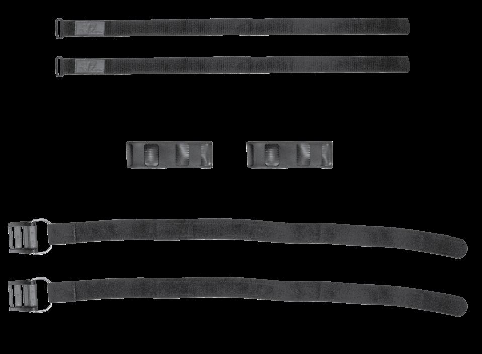
11 3. SureLock Weight Pouches and Sheaths (Figs. 3 & 4) Can be mounted horizontally / vertically on the side of the vest or vertically on the back of the harness. SureLock weight pocket positioning will depend on type of diving apparatus used. 11 Fig. 3 Fig Apparatus Attachment Strap Kits (Fig. 5) Female 2 buckles for the MK25 and MK16 are attached to CSAV. Strap kits are provided for each of the three diving apparatuses: MK16, MK25 & single and twin SCUBA cylinders. MK25 Kit MK16 Kit Twin and Single Cylinder Kit Fig. 5
. Air is added to the CSAV by opening each cylinder valve.")


 fitting cover will keep water and debris out of the inflators key components (Fig.")
12 12 CSAV Technical Manual SYSTEM LAYOUT Auxiliary Air Cylinder The auxiliary air cylinders are attached to the CSAV by means of a threaded hand fitting (Fig. 6). Air is added to the CSAV by opening each cylinder valve. Required for closed circuit and semiclosed circuit diving. P/N Z P/N Z Fig. 6 Powerline Airway The Powerline airway comes standard on the CSAV. It can be orally inflated or a LP inflator hose can be added for power inflation while using open circuit SCUBA. MP air is supplied to the inflator assembly by a quick disconnect inflator hose attached to the first stage regulator. Air can be added to the vest by pushing the power inflator button or orally through the mouthpiece by pushing the oral inflator button. The quick disconnect (QD) fitting cover will keep water and debris out of the inflators key components (Fig. 7). MOUTHPIECE POWER INFLATOR BUTTON QD FITTING COVER OVER PRESSURE RELIEF VALVE / RAPID EXHAUST VALVE ORAL INFLATOR BUTTON LP INFLATOR HOSE Fig. 7
. Each has a secure hook and loop closure. These are to be used with two 4 lb.")
13 13 Integrated Non-Ditchable Weight Pockets The CSAV is designed with two internal weight pockets capable of holding two block or soft weights. These pockets are located on the rear/inside of the CSAV (under the comfort pad). Each has a secure hook and loop closure. These are to be used with two 4 lb. soft weights for MK25 and may be used for other configurations as well (Fig. 8). Weight Pockets Fig. 8


14 14 CSAV Technical Manual SureLock Weight Integrated System The CSAV is supplied with two different options of SureLock weight system, two 10-lb. pouches/ sheaths and two 20-lb. pouches/sheaths. This is a positive locking mechanical release weight system. Each pouch is capable of holding up to 10 lb. (4.5 kg) or 20 lb. (9 kg) of weight. Block or soft weights can be used. The sheath portion can be attached to the CSAV using the built in MOLLE style straps. The weight pouches can then be inserted or removed in the same manner as other weight integrated diving vests. When the weight pouch is inserted in the sheath, the diver should hear and feel the pouch click in. This assures the diver that the weight pouch is firmly and securely attached (Figs. 9-12). 10lb pocket assembly front 20lb pocket assembly front Fig. 9 Fig lb pocket assembly back 20lb pocket assembly back Fig. 11 Fig. 12
. 1. Before attempting to fill the auxiliary air cylinder, ensure that the fill adapter and valve are completely dry - especially in the area surrounding the valve outlet.")

15 15 Filling the Auxiliary Air Cylinder To fill the cylinder, you will need an optional fill adapter: Aqua Lung part number (Fig. 13). 1. Before attempting to fill the auxiliary air cylinder, ensure that the fill adapter and valve are completely dry - especially in the area surrounding the valve outlet. Examine the cylinder markings to verify that it is rated for a fill pressure of 3,000 PSI (206 BAR). 2. Using a calibrated pressure gauge, check the supply cylinder is filled to 3,000 PSI (206 BAR). It is very important to ensure that the auxiliary air cylinder is filled to its total capacity, but not overfilled. WARNING: DO NOT attempt to fill the cylinder if the markings indicate that it is rated for a different fill pressure other than 3,000 PSI (206 BAR). Doing so may result in rupture or explosion in the event of fire or overfilling. Instead, immediately return the unit to a qualified technician and do not use under any circumstances. Fig Inspect the o-ring at the end of the fill adapter to make sure it is in good condition. Thread the adapter onto the threaded outlet boss on the cylinder valve until finger tight (Fig. 14). Check O-ring Fig. 14

16 16 CSAV Technical Manual 4. Loosen the yoke knob. While supporting the auxiliary cylinder in one hand, attach the adapter to a fully pressurized 3,000 PSI (206 BAR) scuba cylinder (Fig. 15). Bleed Valve Yoke Knob Fig Close the bleed valve on the adapter by turning clockwise until finger tight. WARNING: DO NOT attempt to fill the auxiliary cylinder from a supply cylinder which contains more than 3,000 PSI (206 BAR). Doing so may weaken and damage the cylinder. 6. Open the handwheel on the auxiliary cylinder counterclockwise until the valve is completely open. 7. VERY SLOWLY open the valve on the scuba cylinder. NOTE: Always fill the auxiliary cylinder as slowly as possible by turning the handwheel of the supply valve slowly to control the rate of fill. Rapid filling will generate heat and will result in an incomplete fill after the cylinder cools. If the cylinder is warm to the touch afterward, the fill rate was too rapid. 8. Close the valve of the supply cylinder and then the valve of the auxiliary cylinder. Slowly loosen the bleed valve by turning it counterclockwise to relieve the high pressure air trapped in the adapter. 9. Loosen the yoke knob and remove the adapter from the supply cylinder. Unscrew the adapter from the auxiliary cylinder valve. Place the dust cap back in place and tighten the yoke knob.


.")
17 Attaching the Auxiliary Air Cylinder 1. Before attaching the cylinder, inspect the o-ring located at the tip of the cylinder connector (Fig. 16). 17 Check O-ring Fig Insert the cylinder into the cylinder pocket and align the threaded valve outlet with the cylinder connector. Turn the knurled nut counterclockwise and thread the cylinder connector onto the valve outlet until finger tight (Fig. 17). Fig. 17 CAUTION: Failure to put the cylinder in the cylinder pocket may cause the cylinder connector to separate from the manifold. Inflation Methods The distribution of the buoyancy chamber provides excellent safety performance, either during buoyant ascent (vertical stability) or at the surface (natural support position with head and shoulders out of the water). The unique split horse collar design of the CSAV is easy to don, ditch and comfortable to wear. The CSAV can be inflated by: Power inflator (SCUBA regulator). Oral inflator. Pressurized HP or MP air cylinders.
 to inflate the vest.")
18 18 CSAV Technical Manual Using the Oral Inflator To orally inflate your vest, place your lips on the oral inflator mouthpiece (A) and exhale a small amount of air into the mouthpiece. This will purge any water that may be still in the housing. While continuing to exhale into the mouthpiece, depress the oral inflator button (B) to inflate the vest. Immediately after exhaling, release the oral inflator button to prevent air from escaping (Fig. 18). E C D A B Fig. 18 Using the Power Inflator For the power inflator to work, the low pressure inflator hose must be connected. To connect the LP inflator hose, grip the grooved sleeve (C) with your thumb and forefinger and slide the sleeve back. Place the hose fitting over the quick disconnect (QD) fitting (D), and push inward while releasing the sleeve. Check to ensure the hose is securely attached. To inflate your vest with medium pressure air, depress the power inflator button (E). Do not hold the inflator button depressed continuously underwater, as this could cause you to become excessively buoyant. Instead, depress the button in short bursts until you become neutrally buoyant (Fig. 18). Using the Auxiliary Air Cylinder To inflate the vest using the auxiliary air cylinder, open the cylinder valve by turning the handwheel counterclockwise. Close the cylinder valve when the bladder is adequately filled, otherwise, air will escape from the over pressure relief valve (OPRV). WARNING: DO NOT rely on the power inflator as the only means to inflate your vest. It is important to maintain proficiency in the skill of orally inflating your vest so that you are prepared for an emergency, such as an out of air situation. Deflation Methods Throughout the course of a dive, it may be necessary to release air from the CSAV using one of the two methods described in the following instructions. Each method uses a valve that is in a different location. The method you choose at any time may depend on whether you are making your initial descent feet-first, head-first, or maintaining neutral buoyancy underwater. Always remember to utilize the valve that is at the highest point on the bladder (closest to the surface), depending on your position in the water.


 of pull is needed to open the rapid exhaust valve (REV). Excessive force is not needed.")
19 19 WARNING: Whenever you ascend, whether intentionally or accidentally, you must simultaneously vent air from the vest as needed to maintain buoyancy control. If air is allowed to expand inside the vest unchecked, you may experience a rapid, uncontrolled ascent, which could lead to serious injury or death if not immediately corrected. To regain buoyancy control during an uncontrolled ascent, you must continuously exhaust air from the vest until you have stopped ascending. Deflation using the Rapid Exhaust Valve Inside the inflator s chevron hose is a stainless steel cable that attaches the inflator to the dual valve at the top of the Powerline airway. You can vent air from the CSAV by firmly pulling straight down on the lower Powerline inflator assembly. Once resistance is felt, only 1/4 in (7mm) of pull is needed to open the rapid exhaust valve (REV). Excessive force is not needed. The rapid exhaust valve (REV) provides an effective and convenient way to vent air from the vest while in either an upright or face down swimming position (Fig. 19). It also functions as an over pressure relief valve (OPRV) that will open automatically to relieve excessive air pressure. This feature is very critical for preventing stress or damage to the bladder (Fig. 20). Fig. 19 Fig. 20 CAUTION: The proper function of the over pressure relief valve is vital to prevent damage to the bladder. Unauthorized service or tampering may render these valves inoperable, and could cause the bladder to leak or burst. This type of damage is not repairable and is not covered under warranty. WARNING: Most training agencies recommend that you descend in an upright, feet-first position, in order to maintain a slower and more controlled descent. This is especially true if you experience difficulty equalizing your ears or if you are descending in low visibility conditions. Deflation using the Oral Inflator To deflate the CSAV using the oral inflator, lift the inflator body to its highest possible position (above the head). Press the oral inflator button (Fig. 18B, previous page) to start venting air. This method is most effective on the surface for making an initial feet-first descent, but is not very useful while you are in a facedown swimming position. NOTE: Depressing the oral inflator button while the vest is empty may cause water to enter the air bladder.


20 20 CSAV Technical Manual Areas of Adjustment The harness has five areas of adjustment in order to achieve the best possible fit for a wide range of divers. 1. Torso Length Adjustment - Find the metal knurled adjusters located at the top corner of the waist belt retainer. Adjust the webbing length and secure the excess by using the hook & loop web retainers at the end of the webbing (Fig. 21). Fig Torso Girth Adjustment - The CSAV has three release buckles attached to the front of the container. Don the CSAV, connect and adjust the front buckles. Secure the excess by using the hook & loop web retainers at the end of the webbing. Lastly, to provide a snug fit, locate and adjust the webbing straps that connect the container to the harness, located on the back of the harness (Fig. 22). Fig. 22
.")
 - The container retainer straps are designed to allow the diver several additional inches of")
. Fig. 24 5. Crotch Strap Adjustment - An adjustable crotch strap is provided to prevent the CSAV from riding up when inflated.")
21 3. Waist Belt Adjustment - The CSAV waist belt range of adjustment is inches, it can resize by adjusting the hook & loop overlap and adjustable straps in or out as needed for a snug fit around the body (Fig. 23). Secure the excess strap by using the hook & loop web retainers at the end of the webbing. 21 Fig Rear Shoulder Adjustment (Container Retainer Straps) - The container retainer straps are designed to allow the diver several additional inches of room if needed. Adjust the webbing length and secure the excess strap with the hook and loop retainers located in the ends of the webbing strap. (Fig. 24). Fig Crotch Strap Adjustment - An adjustable crotch strap is provided to prevent the CSAV from riding up when inflated. There is a hook & loop strap provided under the comfort pad to allow stowage of the crotch strap if not needed (Fig. 1).

 buckle thorough the sewn in loop of the crotch strap. 3. Fasten the lower internal waistband buckle.")
. 7. Check all areas of adjustment are properly fit.")
22 22 CSAV Technical Manual DONNING AND ADJUSTMENT PROCEDURES Donning and Adjustment (Figs. 25 & 26) 1. Insert your arms thorough the arm slots as if you were putting on a jacket. 2. If the crotch strap (A) is to be used, bring it up between your legs and insert the internal waist belt (B) buckle thorough the sewn in loop of the crotch strap. 3. Fasten the lower internal waistband buckle. B A Fig Secure the lower buckle (C) and upper buckle (D). 5. Secure the chest strap (E). 6. Tighten torso girth straps (F). 7. Check all areas of adjustment are properly fit. Remove CSAV and readjust if necessary. E C F D Fig. 26
. Fig. 27 2.")
23 23 AIR BLADDER REMOVAL AND INSTALLATION PROCEDURES 1. Hardware must be removed prior to removing the bladder. Unscrew the cylinders from the cylinder connectors. Next, unscrew the cylinder connectors from the bladder (Fig. 27). Fig Remove the Powerline airway (located on the left shoulder) from the CSAV by unscrewing the collar at the base of the rapid exhaust valve (REV) (Fig. 28). Fig. 28

24 24 CSAV Technical Manual 3. Unzip the outer container and remove the bladder (Fig. 29). Fig Stuff the bladder back into the container. Properly align the threaded connectors on the bladder with the holes on the container. Reconnect the inflator, cylinder connectors or caps. Inflate the vest and let sit for one hour to ensure proper air integrity (Fig. 30). CAUTION: Do not use any tools to tighten the Powerline airway, cylinder connectors or caps onto the vest manifold. Doing so may result in overtightening or cross threading and could cause permanent damage that will require replacement of the bladder. Fig. 30


25 25 DIVE APPARATUS CONFIGURATION Weight Pouch Setup When setting up the CSAV to dive MK16 or SCUBA, the placement and orientation of the weight pouches is left to the discretion of the diver, either mounted vertically or horizontally (Figs. 31 & 32). NOTE: When setting up the CSAV to dive MK25, follow the mandatory weight configurations in the MK25 Setup Section of this manual. Inflation System Setup Fig. 31 Fig. 32 The 1.5 cf. air cylinders used for inflation are mandatory for the MK16 and the MK25. For SCUBA, the primary source for inflating the vest is MP air from the 1st stage regulator through the Powerline airway. It is suggested that the HP cylinder connectors used for MK16 and MK25 be removed from the vest and blanked off using the caps PN (Figs. 33 & 34). Fig. 33 Fig. 34
. Fig. 35 Fig.")
.")
26 26 CSAV Technical Manual SCUBA Setup There is one CSAV strap kit that is designed to fit two existing Aqua Lung made SCUBA cylinder configurations, shown in the two photos below (Figs. 35 & 36). Fig. 35 Fig. 36 Single cylinder, shown with CSAV Strap Kit (PN ). Twin cylinders, shown with CSAV Strap Kit (PN ). NOTE: The four MK25 female buckles may be removed or left in place for SCUBA diving operations (Fig. 37). Fig. 37


27 27 Single Cylinder Setup (Strap Kit PN ) CSAV Strap kit, PN , is used for all aluminium & steel single SCUBA cylinders. NOTE: Pre-soak the nylon webbing in strap kit PN prior to installation. This allows for more flexibility in the straps. The stabilizer straps will not be used in this configuration. 1. Install traction sleeves onto tank bands. Skip the last loop in the traction sleeve, ensure hook and loop is face up. Slide the traction sleeves all the way up to the cam-buckle. (Figs. 38 & 39). DO NOT THREAD TANK BAND THROUGH LAST SLOT U N D E R U N D E R O VE R Fig. 38 Fig Thread both tank bands through the upper and lower tank band loops on rear of the harness until the traction sleeves are tight against the cam buckle (Figs. 40 & 41). Upper Tank Band Loops Lower Tank Band Loops Fig. 40 Fig. 41
. Fig. 42 4.")

 1 3 Fig. 43 Fig. 44 5.")
28 28 CSAV Technical Manual 3. Lay the vest face down on a clean surface. Carefully place the cylinder down on to the center of the vest (Fig. 42). Fig Securing the tank bands (Figs. 43 & 44). Align the cylinder so that there are approximately 12 inches between the lower tank band and the bottom of the cylinder. Follow number sequence and directional arrows molded into cam buckle. Close cam buckle, fastening hook and loop material to secure. 12" 4 2 (ON BACK SIDE) 1 3 Fig. 43 Fig When both tank bands are installed properly, the ends of the tank bands should almost touch the back of the vest as shown. Adjust as needed (Fig. 45). Fig. 45
29 29 INSTALLATION INSTRUCTIONS FOR TWIN TANK CYLINDER BAND KIT (PN ) RECOMMENDED TOOLS 1. Ratchet wrench 3. 1/2 socket 2. Extension 3" or longer 4. 1/2 box wrench 1. Lay the twin tanks on a sturdy table or workbench such that the bottom 8 inches of the cylinders stick off the edge of the table. 2. Unscrew the nut (65) and remove the bolt (64), spacer (62) and back-up plates (63) from the band (60). 3. Slide the band (60) onto the bottom of the twin cylinders so the band is 6 inches from the bottom of the cylinders (Fig. 46). 4. Slide a non-slip cover (61), (ribbed side facing inward) between the band and cylinder. Work the nonslip cover into place across the top circumference of the cylinder. Repeat the process for other side. Turn the twin cylinders over and continue to slide the non-slip covers into place. Make sure the band is centered on top of the non-slip covers. 5. Place the back-up plate (63) onto the bolt (64). Position the spacer (62) between the two holes in the band. Insert the bolt (64) through the hole on the bottom side of the band (the threaded end of the bolt should be facing you) and through the spacer (62). Hold these parts in place with your finger. NOTE: The bolt will not be inserted through the other hole until step 6 has been completed. 6. Place the other back-up plate (63) on the band such that the two holes align. Press up on the bolt (64) and guide the threaded end of the bolt through the band and back-up plate. Take the nut (65) and thread it onto the bolt while simultaneously pressing down on the center of the band. You only need to engage the first couple of threads. 7. While holding the head of the bolt with a 1/2 wrench, tighten the nut with a 1/2 socket wrench. Tighten the nut until the band is tightly secure to the cylinder. 6 Fig. 46

30 30 CSAV Technical Manual Twin Cylinder Setup (Strap Kit PN ) CSAV Strap kit, PN , is used for all aluminium & steel twin SCUBA cylinders. NOTE: Pre-soak the nylon webbing in strap kit PN prior to installation. This allows for more flexibility in the straps. The stabilizer straps will not be used in this configuration. CAUTION: Do not remove the lower metal band. Doing so could cause major damage to the manifold while handling cylinders. 1. Using a 1/2 inch socket or wrench, remove the upper metal band. Lay the cylinder set down for safety after removal of the upper band (Figs. 47 & 48). Fig. 47 Fig Install traction sleeves on to tank bands. Skip the last loop in the traction sleeve, ensure hook and loop is face up. Slide the traction sleeves all the way up to the cam buckle. (Figs. 49 & 50). DO NOT THREAD TANK BAND THROUGH LAST SLOT U N D E R U N D E R O VE R Fig. 49 Fig. 50
 on the rear of the harness from the outside to the")


31 3. Thread the tank bands through both lower tank band loops (one on each side) on the rear of the harness from the outside to the middle. Hook and loop material should be facing inwards on both tank bands. Pull the tank bands through until the traction sleeves on both bands are tight against the lower tank band loops and butting up against the cam buckle (Figs ). 31 Stabilizer Strap Loops Upper Tank Band Loops Lower Tank Band Loops Fig. 51 Fig. 52 Fig Weave both stabilizer straps through the stabilizer strap loops located near shoulders from the outside to the inside. Allow 6 inches of strap to extend beyond loop as shown (Fig. 54). 6" 6" Fig. 54

. Fig.")

32 32 CSAV Technical Manual 5. Lay the CSAV face down on a clean surface. Carefully lay the twin cylinders down onto the vest while feeding the ends of the tank bands between the cylinders above the lower tank bands (Fig. 55). 12" 6" 6. Securing the tank bands: (Figs. 56 & 57). Fig. 55 Align cylinders so that there are approximately 12 inches between the tank straps and the bottom of the cylinders. Follow the number sequence and directional arrows molded into the cam buckle. Close the cam buckle and fasten hook and loop to secure. 12" 4 2 (ON BACK SIDE) 1 3 Fig. 56 Fig. 57

33 33 7. Securing the stabilizer straps: Weave the ends of the stabilizer straps between the cylinders. Feed the ends through the bale rings and tighten. Fasten hook and loop to secure. 8. When both tank bands and both stabilizer straps are installed properly, the ends should lay between the cylinders as shown (Figs. 58 & 59). Fig. 58 Fig. 59

. Fig. 60 Fig. 61 2. Shorten the shoulder straps to keep the MK16 high on the back.")

.")

34 34 CSAV Technical Manual MK16 Setup (Strap Kit PN ) 1. Attach all five straps to the MK16 using dog bones. Straps consist of two shoulder straps, two waist straps and one Y-crotch strap (Figs. 60 & 61). Fig. 60 Fig Shorten the shoulder straps to keep the MK16 high on the back. 3. Prior to mounting the MK16, ensure the CSAV female buckles are attached to the harness as follows: a. Top/Shoulder Buckles: Attached to the forward set of metal web adjusters sewn into the upper area of the harness shoulder straps (Figs. 62 & 63). NOTE: Most divers will use the forward sets of metal web adjusters. The rear set of metal web adjusters behind these are for very tall, large chested divers. b. Bottom/Waist Buckles: Attached to the front set of metal web adjusters sewn into the front ends of the harness shoulder straps (Figs. 62 & 63). REAR SET REAR SET FORWARD SET FRONT SET FORWARD SET FRONT SET Fig. 62 Fig. 63


35 35 MK25 Setup (Strap Kit PN ) WARNING: The following weight configurations are mandatory to dive the MK25 with the CSAV. MK25 with T-bit, a minimum of 16 lbs. must be worn. Install a 4 lb. weight in each of the two internal/non-ditchable weight pouches. Refer to Integrated Non-Ditchable Weight Pockets Section. Install a 4lb. weight in each of the two back mounted SureLock ditchable weight pouches (Fig. 64). MK25 with FFM: Weights are diver preference per mission requirements. WARNING: Gear placement on CSAV may also affect head up flotation. Test dive all new gear configurations prior to use. NOTE: Please note that additional weights, chosen to meet each diver s individual needs, will be placed in the SureLock weight pouches. Fig Attach the four straps to the MK25. Straps consist of two shoulder and two waist straps (Figs. 65 & 66). Fig. 65 Fig. 66
36 36 CSAV Technical Manual 2. Prior to mounting the MK25, ensure the female MK25 buckles are attached as follows (Fig. 67): Top shoulder buckles, (2 ea.): Attach to angled MOLLE loops located at the top of the CSAV front right and left shoulders. Bottom waist buckles, (2 ea): Attach to the MOLLE loops located just forward of the cylinder connectors. Fig Attach the MK25 to the CSAV by connecting the male buckles on the MK25 to the female buckles at the shoulders and the waist of the CSAV. Adjust the straps as needed (Fig. 68). Fig. 68 NOTE: Please note that in newer versions of Strap kit PN , thumb loops have replaced plastic D-rings.
37 37 Pre-dive inspection checklist Diver Name Date CSAV Number WARNING: Before each use, the CSAV must be given a thorough visual inspection and functional test. NEVER dive with a CSAV that shows signs of damage to its bladder or valves until it has received a complete inspection and service. 1. Inspect all buckles and hardware on the harness and container. 2. Install LP inflator hose or two fully charged air cylinders 3,000 PSI (206 BAR) to the vest. 3. Use one of the two inflation methods listed below to check the vest is functioning properly. Each will vary depending on equipment being used: a) Inflate the CSAV with the power inflator button until the over pressure relief valve (OPRV) opens to relieve excess pressure (See Inflation Methods). Verify the OPRV re-seats and keeps the bladder fully inflated. b) Slowly open one cylinder valve and fully inflate the CSAV until the over pressure relief valve (OPRV) opens to relieve excess pressure (See Inflation Methods). Close cylinder valve. Verify the OPRV re-seats and keeps the bladder fully inflated. Refill cylinder prior to diving. 4. While the CSAV is still inflated, check the function of both the rapid exhaust valve (REV) and the oral inflation valve. Ensure rapid and unobstructed exhaust from each valve, verify each valve re-seats and no leakage is detected. (See Deflation Methods). 5. Fully inflate CSAV once again and listen closely for any signs of leakage. 6.Verify that all harness straps are connected properly in the correct mission configuration. Verify all buckles operate correctly. 7. Diving Supervisor check previous steps and record deficiencies below. WARNING: If any leakage can be heard or if the bladder begins to deflate within ten minutes, DO NOT attempt to use the CSAV until it has been repaired by a trained technician. Remarks Divers Signature Diving Supervisor Signature
38 38 CSAV Technical Manual Post-dive inspection checklist Diver Name Date CSAV Number NOTE: Following the post-dive maintenance procedures is essential to ensure the CSAV remains in proper working condition. Initials 1. Remove the Powerline inflator assembly from the CSAV by unscrewing the collar at the base of the REV. 2. Direct fresh water into the manifold opening on the vest until the bladder is 1/4 full. Reinstall the Powerline inflator assembly onto the CSAV. 3. Thoroughly shake the bladder so the water rinses the entire inside of the bladder. 4. Remove the Powerline inflator assembly and two cylinder connectors/caps to allow water to drain out of the bladder. Rinse out the Powerline airway assembly, cylinder connectors/caps. Hang the Powerline inflator assembly upside down to allow complete drainage, utilizing the hook and loop retainer on the vest. Allow CSAV to dry completely. 5. Ensure no water remains inside the bladder. Reinstall Powerline airway and cylinder connectors caps. Inflate the CSAV and check for leaks. 6. Store CSAV deflated in a clean, dry area away from extreme temperatures: no greater than 120 F/49 C and no less than 0 F/-18 C. 7. Diving supervisor check previous steps and record deficiencies below. Remarks Divers Signature Diving Supervisor Signature
39 39 POST DIVE CARE & MAINTENANCE With proper care, the CSAV will provide many years of reliable service. The following preventive maintenance must be performed to extend the life of the CSAV: 1. Avoid prolonged exposure to direct sunlight and extreme heat. Nylon fabric can quickly fade when exposed to the sun s ultraviolet rays and extreme heat may damage the welded bladder seams Avoid repeated or prolonged use in heavily chlorinated water, which can cause the CSAV fabric to discolor and decay prematurely. Do not allow the CSAV to chafe against any sharp objects or rough surfaces that could abrade or puncture the bladder. Do not set or drop heavy objects such as cylinders or block weights on the CSAV. Avoid any contact with oil, gasoline, aerosols or chemical solvents. After diving, give the CSAV a thorough fresh water rinse and check for water inside the air bladder. If there is any water inside the bladder, it must be rinsed out with fresh water using the following procedure: a) Remove the Powerline inflator assembly from the CSAV by unscrewing the collar at the base of the REV. b) Direct fresh water into the manifold opening on the vest until the bladder is 1/4 full. Reinstall the Powerline inflator assembly onto the CSAV. c) Thoroughly shake the bladder so the water rinses the entire inside of the bladder. d) Remove the Powerline inflator assembly and two cylinder connectors/caps to allow water to drain out of the bladder. Rinse out the Powerline airway assembly, cylinder connectors/caps. Hang the Powerline inflator assembly upside down to allow complete drainage, utilizing the hook and loop retainer on the vest. Allow CSAV to dry completely. e) Ensure no water remains inside the bladder. Reinstall Powerline airway and cylinder connectors/caps. Inflate the CSAV and check for leaks. f) Store CSAV deflated in a clean, dry area away from extreme temperatures: no greater than 120 F/49 C and no less than 0 F/-18 C.


.")


 and remove the cylinder valve from the cylinder by turning valve body (24)")

 from the valve body (24) using a 3/8 flex")
40 40 CSAV Technical Manual Cylinder Valve Maintenance Procedures Note: Before performing any disassembly, refer to the exploded parts drawing, which references all mandatory replacement parts. These parts should be replaced with new and must not be reused under any circumstances regardless of the age of the valve or how much use it has received since it was last serviced. 3. Use the modified screwdriver (pn ), to remove the handwheel nut (13), handwheel (14) and the handwheel washer (15) from the spindle (22). CAUTION: Use only a plastic (p/n or brass o- ring removal tool (p/n ) when removing o-rings to prevent damage to the sealing surface. Even a small scratch across an o-ring sealing surface could result in leakage. Once an o-ring sealing surface has been damaged, the part must be replaced with new. DO NOT use a dental pick or any other steel instrument. Cylinder Valve Disassembly 1. Open cylinder valve counterclockwise and ensure cylinder (29a or 29b) is fully depressurized. Secure cylinder in cylinder vise (pn ) and remove the cylinder valve from the cylinder by turning valve body (24) counterclockwise with a 1-1/16 inch (27mm) crowfoot (pn FC34A) and 3/8 flex handle drive (pn ). When done, remove cylinder from cylinder vise. Note: If the valve seat adapter (27) is not leaking, DO NOT remove, go directly to step Holding the valve body assembly in a vise, unscrew the valve seat adapter (27) from the valve body (24) using a 3/8 flex handle drive (pn ) with 5-mm hex key adapter (pn 8367A23). CAUTION: Loctite 242 is used to hold this part in place in addition to the torque applied during assembly. Note: If the valve seat adapter does not loosen, use a heat gun to heat up the body and adapter to loosen the adhesive. 2. Remove the o-ring (28) from the valve body (24). Use the appropriate o-ring tool (pn or ). Discard o-ring. CAUTION: Do not damage the internal surface of the valve seat adapter.
. Discard o-ring.")
 from the valve body (23) using the spindle (22).")
 socket and 3/8 flex handle")
 from the valve plug (16) using the appropriate o-ring tool (pn")
 from the port of the valve body (24) using a 1/2 (13mm)")
 and gasket (25c) from the port in the valve body.")

41 41 5. Using the brass or plastic o-ring tool (PN or ) remove o-ring (26) from the valve seat adapter (27). Discard o-ring. Remove the old blue Loctite from the valve seat adapter and body. 8. Unscrew the valve seat (23) from the valve body (23) using the spindle (22). Discard valve seat. 6. Holding the valve body assembly in a vise, use a 7/8" (22mm) socket and 3/8 flex handle drive (PN ), remove the valve plug (16) from the valve body (24). Remove the o-ring (17) from the valve plug (16) using the appropriate o-ring tool (pn ). Discard o-ring. 9. Remove the safety plug (25a) from the port of the valve body (24) using a 1/2 (13mm) socket (pn ) and 3/8 flex handle drive (PN ). Discard safety plug. Remove the safety disc, red (25b) and gasket (25c) from the port in the valve body. Discard safety disk and gasket. This Concludes Disassembly of the Cylinder Valve Before beginning reassembly, perform parts cleaning and lubrication in accordance with Procedure A: Cleaning and Lubricating. 7. Remove the spindle (22) from valve body (24). Remove back-up ring (18), o-ring (18), metal washer (20) and plastic washer (21) from the spindle (22). Discard back-up ring, o-ring and plastic washer.

 and screw into the valve body (24) using the spindle (22) until it bottoms against the crown.")

 in a vise, install the burst disk assembly in the following order: gasket (25c), safety disc (25b) and safety plug (25a).")
, metal washer (20), o-ring (19) and backup ring (18).")
 with the red side of the disc facing out of the port on the valve body. Note: DO NOT Lubricate the threads of the safety plug. 4.")
42 42 CSAV Technical Manual NOTE: Before performing any reassembly, it is important to inspect all parts, both new and those that are being reused, to ensure that every part and component is perfectly clean and free of any dust, corrosion or blemishes. Before dressing each o-ring with Christo-Lube, check to ensure it is clean, supple and free of any blemish. 2. Lubricate threads of valve seat (23) and screw into the valve body (24) using the spindle (22) until it bottoms against the crown. WARNING: Use only genuine Aqua Lung parts, subassemblies and components whenever assembling any Aqua Lung product. DO NOT attempt to substitute an Aqua Lung part with another manufacturer s, regardless of any similarity in shape, size or appearance. Doing so may render the product unsafe and could result in serious injury or death. Cylinder Valve Assembly 1. Hold the valve body (24) in a vise, install the burst disk assembly in the following order: gasket (25c), safety disc (25b) and safety plug (25a). Torque the safety plug to 90 in/lb (10.2 Nm) using a 1/2 inch (13mm) socket and Inch Pound torque wrench. 3. Place parts in the following order onto the spindle (22). Lubricated plastic washer (21), metal washer (20), o-ring (19) and backup ring (18). NOTE: The Burst Disk Assembly PN (25) comes as a complete kit, it is to be installed together and cannot be ordered as separate parts. Note: Install safety disc (25b) with the red side of the disc facing out of the port on the valve body. Note: DO NOT Lubricate the threads of the safety plug. 4. Insert the spindle assembly into the valve body (24) ensuring the spindle (22) aligns with the slot in the valve seat (23). Align Spindle w/ slot 5. Lubricate the o-ring (17) and install it on to the valve plug (16). Ensure it is in the groove on the plug below the shoulder. Screw the valve plug (16) back into the body (24) until hand tight. Using a Inch Pound torque wrench and a 7/8 inch (22mm) socket (pn ), tighten the valve plug to 90 in/lbs (10.2 Nm). Ensure the o-ring (17) is seated back inside the valve body (24).
 onto valve body (24). Lightly lubricate the threads of the valve body (24).")

. 7.")
 until it stops. CAUTION: Avoid cross threading the handwheel nut.")


43 43 6. Install washer (15) and handwheel (14) onto spindle (22). 9. Install a new lubricated o-ring (28) onto valve body (24). Lightly lubricate the threads of the valve body (24). Secure cylinder in cylinder vise (pn ) and screw the cylinder valve into the cylinder by turning valve body (24) clockwise until hand tight. Using a 1-1/16 inch (27mm) crowfoot (pn FC34A) and Foot Pound torque wrench, tighten the valve assembly into the cylinder to 25 ft/lbs (34 Nm). 7. Secure the handwheel (14) to the spindle (22) by placing the handwheel nut (13) on to the spindle (22) and tighten it down with the modified screwdriver (pn ) until it stops. CAUTION: Avoid cross threading the handwheel nut. If resistance is felt while screwing the handwheel nut on to the spindle, stop and start over. This Concludes Assembly of the Cylinder Valve Cylinder Valve Final Assembly and Testing 1. Fill cylinder to 500 PSI (34 BAR) and listen for audible leaks. Submerge in a fresh water supply and visually inspect valve for any leaks that may be present. If no leaks are detected, fill cylinder to 3,000 PSI (206 BAR), again listen for audible leaks and submerge in fresh water. If any leaks are detected, disassemble valve, replace worn parts, rebuild and retest. Note: If the valve seat adapter (27) was removed, continue with step 8. If it was not removed, proceed to step Lubricate the o-ring (26) and install on the valve seat adapter (27). Apply one drop of Loctite 242 to the threads of the valve seat adapter. Secure the valve body assembly in a vise, using a 5-mm hex key adapter (pn 8367A23) and inch pound torque wrench tighten the valve seat adapter to 90 in/lbs (10.2 Nm).


 off the dual-valve assembly (2).")


 from the vest manifold. Inspect the gasket for damage. If no damage is found, it may be reused.")


. 1.")

44 44 CSAV Technical Manual Powerline Airway Maintenance Procedures Note: Before performing any disassembly, refer to the exploded parts drawing, which references all mandatory replacement parts. These parts should be replaced with new and must not be reused under any circumstances regardless of the age of the valve or how much use it has received since it was last serviced. 4. Using diagonal pliers (pn ), carefully cut and remove the clamp (3). Slide the chevron hose (4) off the dual-valve assembly (2). CAUTION: Use only a plastic (p/n ) or brass o- ring removal tool (p/n ) when removing o-rings to prevent damage to the sealing surface. Even a small scratch across an o-ring sealing surface could result in leakage. Once an o-ring sealing surface has been damaged, the part must be replaced with new. DO NOT use a dental pick or any other steel instrument. Powerline Airway Disassembly 1. Turn the retaining collar and remove the dual-valve assembly (2) from the manifold. Remove the gasket (1) from the vest manifold. Inspect the gasket for damage. If no damage is found, it may be reused. This Concludes the Disassembly of the Powerline Airway NOTE: Before performing any reassembly, it is important to inspect all parts, both new and those that are being reused, to ensure that every part and component is perfectly clean and free of any dust, corrosion or blemishes. Before dressing each o-ring with Christo-Lube, check to ensure it is clean, supple and free of any blemish. WARNING: Use only genuine Aqua Lung parts, subassemblies and components whenever assembling any Aqua Lung product. DO NOT attempt to substitute an Aqua Lung part with another manufacturer s, regardless of any similarity in shape, size or appearance. Doing so may render the product unsafe and could result in serious injury or death. Powerline Airway Assembly 2. Remove QD cover (7). Using diagonal pliers (pn ), carefully cut and remove the clamp (3). 1. Fit the chevron hose (4) over the cable assembly and onto the barrel of the dual valve assembly (2), until it is mated flush at the base of the barrel. Be sure to align the notch on the dual valve body assembly (2) with the notch molded into the chevron hose (4). 3. Pull the chevron hose (4) off the Powerline lower inflator assembly (8). Press the pin (6) out from one side with a pin punch or similar tool to release the cable. Remove QD cover (7) from chevron hose. 2. Lightly fasten a clamp (3) over the chevron hose (4) so that it is evenly seated inside the groove near the end. Position the end of the clamp to either side, where it will not interfere with the LP hose and pull the end of the clamp sufficiently snug. Trim the excess length of the clamp (3) with diagonal pliers (pn ).
 partly through one of the holes of the Powerline lower inflator assembly (8).")
, so that it is flush on both sides of the")
 flat inside the connection manifold and mate the retaining collar of the body dual valve assembly (2) directly")


 with the notch molded into the chevron hose (4).")
 with diagonal pliers (pn 9-45171). 2.")
45 45 3. Slide the QD cover (7) up the chevron hose (4). Insert the cable pin (6) partly through one of the holes of the Powerline lower inflator assembly (8). Pull back the chevron hose (4) to expose the crimped retainer of the cable and pass the retainer over the pin. Insert the pin through the opposite side of the Powerline lower inflator assembly (8), so that it is flush on both sides of the barrel. Powerline Airway Final Assembly and Testing WARNING: Protective eyeware must be worn at all times during testing. 1. Lay the gasket (1) flat inside the connection manifold and mate the retaining collar of the body dual valve assembly (2) directly over it, onto the manifold. Gently turn the collar clockwise to engage the threads, being careful to avoid cross-threading and hold the Powerline airway in the desired position while tightening the retaining collar by hand until snug. CAUTION: Do not use any tools to tighten the retaining collar onto the vest manifold. Doing so may result in overtightening or cross threading and could cause permanent damage that will require replacement of the bladder. 4. Fit the chevron hose (4) over the Powerline lower inflator assembly (8) until it is mated flush at the base of the barrel. Be sure to align the notch on the Powerline lower inflator assembly (8) with the notch molded into the chevron hose (4). Position the end of the clamp to either side, where it will not interfere with the connection of the QD hose and pull the end of the clamp sufficiently snug. Trim the excess length of the clamp (3) with diagonal pliers (pn ). 2. While holding the dual-valve assembly (2) secure, firmly grasp the Powerline lower inflator assembly (8) and pull it in a straight line directly away from the dual-valve assembly. Check the attachment points of the chevron hose (4) at both the dual valve assembly and the Powerline lower inflator assembly. If any signs of damage or decay can be detected, it is important to replace the chevron hose (4) before proceeding any further. This Concludes the Assembly of the Powerline Airway
 approximately six inches above the inflator assembly and pull the chevron hose in a straight line away from the inflator with moderate force while holding the inflator")
 several times to ensure that airflow is unobstructed.")
 at a right angle to the Powerline lower inflator assembly (8), in the direction opposite of the quick disconnect stem.")
 of the dual valve assembly opens to release excess pressure inside the bladder of the vest.")
46 46 CSAV Technical Manual 3. Immerse the inflator and surrounding area of the chevron hose in fresh water to wet the Powerline lower inflator assembly (8). Grasp the chevron hose (4) approximately six inches above the inflator assembly and pull the chevron hose in a straight line away from the inflator with moderate force while holding the inflator secure. Check to ensure that no separation occurs at the attachment point and the chevron hose remains seated flush against the base of the inflator housing. 6. Depress the inflator button of the Powerline lower inflator assembly (8) several times to ensure that airflow is unobstructed. After releasing the button, listen carefully to ensure that the airflow has completely stopped. If internal leakage can be heard, replace the Powerline lower inflator assembly (8). 4. Finally, bend the chevron hose (4) at a right angle to the Powerline lower inflator assembly (8), in the direction opposite of the quick disconnect stem. If the chevron hose shows any sign of separating from the inflator assembly it is important to replace the clamp. 7. Hold the inflator button depressed to fully inflate the vest until the over pressure relief valve (OPRV) of the dual valve assembly opens to release excess pressure inside the bladder of the vest. Check the operation of the over pressure relief valve (OPRV) by inflating the vest repeatedly to ensure that the valve opens to relieve excess pressure, yet closes immediately to allow the bladder of the vest to remain taut and fully inflated. 5. Verify that the first stage regulator which the Powerline will be used with has been recently serviced and is adjusted to a stable MP of PSI (9-10 BAR). Attach the first stage to a cylinder filled to 3,000 PSI(206 BAR). Connect the Powerline to the first stage via the quick disconnect LP hose. Slowly open the valve of the supply cylinder to pressurize the regulator. 8. Press the deflation button and then pull down on the chevron hose to test the rapid exhaust valve (REV) to ensure a rapid and unobstructed exhaust using both methods of deflation. Fully inflate the vest once again and disconnect the Powerline from the quick disconnect hose to listen closely for any signs of leakage. CAUTION: Before pressurizing the first stage, it is important to have a properly adjusted second stage attached to the first stage. This will provide a safety relief valve if the MP exceeds 145 PSI (10 BAR). Failure to relieve increasing MP may result in damage to the LP hose. 9. If any leakage is heard or if the vest has begun to deflate within one hour, fully inflate the vest once again with the Powerline inflator and hold the entire vest submerge in fresh water for at least one minute to determine the source of leakage. During this time carefully observe the Powerline for any signs of bubble formation indicating a leak, especially around the inflator buttons and vest connections. If a continuous leak is detected, the Powerline must be examined for damage, contamination of the seals and seating surfaces. If contamination or damage is found, replace the component. Note: If leakage is not immediately detected, allow the vest to stand for at least one hour to ensure that none exists. This Concludes Final Assembly and Testing of the Powerline Airway
47 47 Precautions and Warnings: INSTRUCTIONS FOR BC Repair KIT (PN 42611) WARNING: Do not attempt to perform these procedures using patches or adhesives other than those provided in the BC Repair kit, PN WARNING: Do not attempt to patch a hole or tear which is larger than 3/4 in diameter or length. WARNING: Do not attempt to patch a tear or puncture which is located directly over or within 2 inches of a seam or internal baffle. WARNING: Adhesive should only be applied in a room with plenty of cross ventilation. Carefully read all cautions on the label of the adhesive and avoid inhaling vapors. 1. Inspect the material of the bladder surrounding the hole or tear to ensure that it is perfectly clean and dry. Rinse and dry the bladder to clean if necessary. 2. Check to ensure that the patch extends at least twice the diameter or length of the holes or tear on all sides. 3. Apply a generous coat of Weld-On 4784 Vinyl adhesive to the material of the bladder surrounding the hole or tear. Allow this preliminary coat to set for at least twenty four hours. CAUTION: It is important to prevent any adhesion between the internal surfaces of the bladder caused by the entrance of adhesive through the hole or tear. Position the bladder as needed to maintain a separation of the bladder at the point of the hole or tear. 4. After twenty four hours have elapsed, apply a generous second coat of adhesive to the material of the bladder surrounding the hole or tear and to the glossy surface only of the patch. Wait exactly twenty minutes. 5. After twenty minutes have elapsed, apply a third coat of adhesive to the bladder material and a second coat to the patch. Wait ten minutes for this coat to grow tacky and immediately apply the patch over the hole or tear, using a small roller to press out any pockets of air that may be present between the patch and bladder material. Position a 5 pound soft weight pouch directly over the patch to apply pressure and allow exactly one hour for the patch to set. NOTE: DO NOT allow the patch to set for more than one hour before performing the next step. 6. Partially inflate the vest no more than 3/4 full, causing the inner surfaces of the bladder to separate if any adhesion has occurred. Apply a final coat of adhesive over the entire patch area. Allow twenty four hours to completely cure and then fully inflate the vest to ensure that leakage is no longer present. If the vest does not remain completely full for at least one hour, immerse it in fresh water to determine the source of leakage and repair as needed.
 101215 Adapter, Tank Fill Charging cylinder (46) 944022 Kit, O-ring, Tool Removing and installation of o-rings 103102 820466 (2 oz.")
 9-44363 3/8 Drive, Flex Handle (Sears) Removal of Valve/Connector Parts 100398 Inserts, Tool Vise Jaw (For Existing Shop Vise) Removal/Installation of Cylinder Valve (45) 100397 Tool, Bottle Vise,")
48 48 CSAV Technical Manual Table 1: LIST OF TOOLS PART # DESCRIPTION APPLICATION Tool, Pliers Diag. Small Removal/Installation of Clamp (3) Adapter, Tank Fill Charging cylinder (46) Kit, O-ring, Tool Removing and installation of o-rings (2 oz.) Tool, Pick Plastic (5 pk) Christo-Lube MCG 111 Removing and installation of o-rings Lubrication of O-rings/Parts (16 oz.) /8 Drive, Flex Handle (Sears) Removal of Valve/Connector Parts Inserts, Tool Vise Jaw (For Existing Shop Vise) Removal/Installation of Cylinder Valve (45) Tool, Bottle Vise, Table Mount Secures Cylinder (29a or 29b) for Removal/Installation of Cylinder Valve (45) 8367A23 Hex Key Adapter 5mm Removal/Installation of Valve Seat Adapter (27) 5mm key FC34A Crowfoot 1-1/16 In (27mm) Snap-On Removal/Installation of Valve (45) N/A Small Punch Removal/Installation Retaining Pin (6) Screwdriver, Medium Blade, Modified Removal/Installation of Cylinder Valve Nut (13)
49 49 Table 1: LIST OF TOOLS (continued) PART # DESCRIPTION APPLICATION N/A N/A 3/8 Drive Torque Wrench; 0-15 Nm (0-132 in/lbs) Range 3/8 Drive Torque Wrench; Nm (0-81 ft/lbs) Range Torque Parts Torque Parts Socket, 7/8 (22mm) (3/8 Drive) Removal/Installation of Valve Plug (16) /2 (13 mm) Socket Removal/Installation Burst Disk Assembly (25) Removal/Installation Twin Cylinder Band Nut (62) N/A 1/2 Box Wrench Removal/Installation Twin Cylinder Band Bolt (61)
50 50 CSAV Technical Manual Table 2: Torque Specifications PART # DESCRIPTION / KEY ITEM # TORQUE Plug, Valve, Mag (16) 90 in/lbs (10 Nm) Body, Valve, Mag (24) 25 ft/lbs (34 Nm) Safety Plug (25) 90 in/lbs (10 Nm) Adapter, Valve Seat, Mag (27) 90 in/lbs (10 Nm) Table 3: Recommended Cleaners and Lubricants LUBRICANT/CLEANER APPLICATION SOURCE Christo-Lube MCG 111 All o-rings Aqua Lung, PN or Lubrication Technologies 310 Morton Street Jackson, OH (800) CAUTION: Silicone rubber requires no lubrication or preservative treatment. DO NOT apply grease or spray to silicone rubber parts. Doing so may cause a chemical breakdown and premature deterioration of the material. Oakite #31 Acid bath for reusable stainless steel and brass parts. Oakite Products, Inc. 50 Valley Road Berkeley Heights, NJ CAUTION: Do not use muriatic acid for the cleaning of any parts. Even if strongly diluted, muriatic acid can harm chrome plating and may leave a residue that is harmful to o-ring seals and other parts. White distilled vinegar Non-ionic Liquid dishwashing detergent (diluted with warm water) Acid bath for reusable stainless steel and brass parts. Degreaser for brass and stainless steel parts; general cleaning solution for plastic and rubber. Household grade Household grade
51 51 Procedure A: Cleaning and Lubricating Cleaning Brass and Stainless Steel Parts 1. Preclean in warm, soapy water* using a nylon bristle tooth brush. 2. Thoroughly clean parts in an ultrasonic cleaner filled with soapy water. If there are stubborn deposits, household white distilled vinegar (acetic acid) in an ultrasonic cleaner will work well. DO NOT place plastic, rubber or silicone or parts in vinegar. 3. Remove parts from the ultrasonic cleaner and rinse with fresh water. If tap water is extremely hard, place the parts in a bath of distilled water to prevent any mineral residue. Agitate lightly and allow to soak for ten minutes. Remove and blow dry with low pressure (25 PSI) filtered air and inspect closely to ensure proper cleaning and like-new condition. Cleaning Plastic & Rubber Parts Parts made of plastic or rubber, such as Powerline lower inflator assembly, dual valve assembly, chevron hose, etc., may be soaked and cleaned in a solution of warm water mixed with mild dish soap. Use only a soft nylon toothbrush to scrub away any deposits. Rinse in fresh water and thoroughly blow dry, using low pressure filtered air. CAUTION: Do not place plastic and rubber parts in acid solutions. Doing so may alter the physical properties of the component, causing it to prematurely degrade and/or break. Cleaning Hoses 1. Hose fittings: Ultrasonically clean with soapy water*, vinegar OK on tough corrosion (only hose ends). 2. Run soapy water through hose if needed. 3. Thoroughly rinse with fresh water (hang with hose ends down). 4. Blow out hose before installing. Lubrication and Dressing All o-rings should be lubricated with Christo-Lube MCG 111. Dress the o-rings with a very light film of grease and remove any visible excess by running the o-ring between thumb and forefinger. Avoid applying excessive amounts of Christo-Lube grease, as this will attract particulate matter that may cause damage to the o-ring. *Soapy water is defined as household grade liquid dishwashing detergent diluted in warm water.


52 52 CSAV Technical Manual powerline w/ dual valve exploded view Airway Complete, Powerline Key # P/N Description Qty Airway Complete, Powerline Gasket, Connector Seal Dual Valve Assembly Clamp, Black, Plastic Tie Hose, Chevron, Powerline Clip, Chevron Hose Pin, Retaining S/S Cover, Q/D, Powerline Lower Inflator Assy, Powerline, Char Low Pressure Hose O-ring LP Inflator Hose O-ring Valve, Schrader


53 53 CYLINDER valve exploded view In/lbs (10 Nm) 14 25a 25b 25c 25 29a or 29b Ft/lbs (34 Nm) In/lbs (10 Nm) Key # P/N Description Qty Kit, Maintenance, Cylinder Valve Z Nut, Handwheel, Mag Handwheel Washer, Handwheel Z Plug Valve, Mag O-ring Ring, Backup O-ring Washer, Metal Washer, Nylon Z Spindle, Mag Seat Valve, Non O2, Mag Z Body, Valve, Mag Burst Plug Assembly, Non-Mag 1 25a N/A Safety Plug 1 25b N/A Disc, Safety Red 3,000 PSI 1 25c N/A Gasket Zytel # x O-ring Adapter, Valve Seat, Mag O-ring 1 29a Cylinder 1.5 cf. 3,000 PSI Black, Alum 1 29b Cylinder 1.5 cf. 3,000 PSI Black, Alum Anodized 1 Loctite242 (Blue) 90 In/lbs(10 Nm) Z Valve Assembly w/ 1.5 cf Cylinder *PART NUMBERS IN BOLD ITALICS ARE INCLUDED IN VALVE REBUILD KIT P/N Z Cylinder Valve Connector Key # P/N Description Qty O-ring Z Connector, Cylinder Valve, Fixed, Mag


, 10 lb, Blk, Pckgd 2 55 769084 WT Pouch, (ea), 20 lb, Blk, Pckgd 2 56")
54 54 CSAV Technical Manual 32 CSAV Components CSAV Parts List Key # P/N Description Qty Kit, Buckle, F, MK25, MMJ Container, CSAV Bladder, MMJ, Pckgd Belt, Waist w/ M-F Buckles, MMJ Airway Complete, Powerline Comfort Pad, Pckgd Pocket, 1.5 HP Cylinder, Blk, MMJ Low Pressure Hose Strap, Container Retainer, MMJ Harness, Adjustable, CSAV Strap, Crotch, MMJ Gasket, Connector Seal Z Connector, Cyl Valve, Fixed, Mag Cap, Universal Connector Z Valve Assy, Mag 2 Key # P/N Description Qty Z Valve Assy, w 1.5 cf. Cylinder, Mag Hose Retainer, MMJ Drop Belt Loops Retainer, 1.0 Webbing, MMJ Retainer, 1.5 Webbing, MMJ Retainer, 2.0 Webbing, MMJ WT Sheath, (ea), 20 lb, Blk, Pckgd WT Pouch, (ea), 20 lb, Blk, Pckgd WT Sheath, (ea), 10 lb, Blk, Pckgd WT Pouch, (ea), 20 lb, Blk, Pckgd Weight, Soft 4lb, Navy Blue Kit, SCUBA Strap, CSAV Single & Twin Kit, Strap, CSAV - MK Kit, Strap, CSAV - MK25 1


55 55 CSAV Components
56 56 CSAV Technical Manual TWIN CYLINDER BAND EXPLODED VIEW Kit, Twin Tank Cylinder Band Key # P/N Description Qty Band, Bottom Twin Cover, Non-Slip Tank Band Spacer, Twin Cyl Plate, Back-up Bolt, X 4, SST Nut, 5/16-18 Hex SST 17/64 1
57 57 SPARE PARTS KITS Kit, Spare Parts, Field, CSAV PN Description Qty Z Connector, Cyl Valve, Fixed, Mag Screw, Threaded, 3/8, S/S, Male Barrel, Threaded, 1/4, S/S, Female Gasket, Connector Seal Cap, Universal Connector Low pressure hose, Airway, Complete, Powerline Kit, Strap, CSAV, MK Kit, Strap, CSAV, MK Kit, SCUBA Strap, CSAV Single & Twin Bladder, MMJ, Packaged Case, Pelican 1500, w/ Pick Foam, Blk Kit, buckle set, 1.0 /1.5 /2.0, CSAV Z Valve Assembly w/ 1.5 cf. Cylinder, Mag Hex Key, L Shape, 1/8, Nickle Plated Screwdriver, Medium Blade, Modified Kit, Maintenance, Cylinder Valve Key # P/N Description Qty N/S Kit, Maintenance, Cylinder Valve Z Connector, Cylinder Valve, Fixed, Mag Key # P/N Description Qty O-ring 1 ACCESSORIES Kit, Twin Tank Cylinder Band P/N Description Kit, Twin Tank Cylinder Band


58 58 CSAV Technical Manual Kit, LPIS Complete P/N Description Qty Pocket, Bottle 3.0 LP Cylinder, Blk, MMJ Low Pressure Inflation System, 33 Hose Fill Adapter, SCUBA Tank, HABD/SEA 1 P/N Description Kit, MMJ Bag * MMJ bag is designed to hold CSAV plus accessories P/N Description Adapter, Tank Fill, Atlantis BC * For filling Z, , cylinders


59 59 P/N Description Kit, Strap, Buckle, M, Front Mount, MMJ, 40MM P/N Description Valve Assy, w/ 3.0 cf. Cyl, CSAV, 300 ft Pocket, Bottle 3.0 Cyl, 300 ft, Blk, CSAV Valve Assy, w/ 1.5 cf. Cyl, Blk, Andz, Mag
CSAV. Combat Swimmer Assault Vest. Rev.05/11
 CSAV Combat Swimmer Assault Vest technical manual Rev.05/11 2 CSAV Technical Maintenance Manual COPYRIGHT NOTICE This owner s manual is copyrighted, all rights reserved. It may not, in whole or in part,
SURFACE SUPPLIED HARNESS
 SURFACE SUPPLIED HARNESS USER S MANUAL REV 4/10 2 Surface Supplied Harness User s Manual Copyright Notice This owner s manual is copyrighted, all rights reserved. It may not, in whole or in part, be copied,
fenzy x4 technical manual PN (orange) PN (black)
 PN (black)") fenzy x4 technical manual PN 854710 (orange) PN 854420 (black) Copyright Notice This owner s manual is copyrighted, all rights reserved. It may not, in whole or in part, be copied, photocopied, reproduced,
fenzy x4 technical manual PN 854710 (orange) PN 854420 (black) Copyright Notice This owner s manual is copyrighted, all rights reserved. It may not, in whole or in part, be copied, photocopied, reproduced,
Odyssea. non-magnetic. technical manual
 Odyssea non-magnetic technical manual 2 Odyssea Technical Manual Copyright Notice This manual is copyrighted, all rights reserved. It may not, in whole or in part, be copied, photo copied, reproduced,
MDB TECHNICAL MANUAL. Military Buoyancy Compensator. Rev. 11/17
 MDB Military Buoyancy Compensator TECHNICAL MANUAL Rev. 11/17 2 MDB Technical Manual COPYRIGHT NOTICE This manual is copyrighted, all rights reserved. It may not, in whole or in part, be copied, photo
CSAV NSW COMBAT SWIMMER ASSAULT VEST TECHNICAL MANUAL REVISED 09/07
 CSAV NSW COMBAT SWIMMER ASSAULT VEST TECHNICAL MANUAL REVISED 09/07 CSAV MILITARY LIFE PRESERVER TECHNICAL MANUAL COPYRIGHT NOTICE This owner s manual is copyrighted, all rights reserved. It may not, in
WSX Sidemount Owner s Manual
 WSX Sidemount Owner s Manual P/N 18418 Rev 05/15 2 WSX Sidemount Owner's Manual INTRODUCTION Congratulations and thank you for choosing Apeks. Your buoyancy compensator meets all existing standards for
LTS BCD USER GUIDE. Hollis (2014) Doc r01 (8/29/14)
 Doc r01 (8/29/14)") LTS BCD USER GUIDE Contents NOTICES...3 DANGERS, WARNINGS, CAUTIONS, & NOTES...3 WARNINGS...4 INTRODUCTION...5 CARE AND MAINTENANCE...5 INFLATOR AND DUMP VALVE USE...6 ATTACHING A TANK...7 INTEGRATED WEIGHT
LTS BCD USER GUIDE Contents NOTICES...3 DANGERS, WARNINGS, CAUTIONS, & NOTES...3 WARNINGS...4 INTRODUCTION...5 CARE AND MAINTENANCE...5 INFLATOR AND DUMP VALVE USE...6 ATTACHING A TANK...7 INTEGRATED WEIGHT
BD Buoyancy Compensator
 BD Buoyancy Compensator User's Manual 2 BD BUOYANCY COMPENSATOR USER'S MANUAL Copyright Notice This owner s manual is copyrighted, all rights reserved. It may not, in whole or in part, be copied, photocopied,
ATLANTIS. Military Buoyancy Compensator TECHNICAL MANUAL
 ATLANTIS Military Buoyancy Compensator TECHNICAL MANUAL 2 Atlantis Technical Manual Copyright Notice This manual is copyrighted, all rights reserved. It may not, in whole or in part, be copied, photo copied,
Rapid Diver System User's Manual
 Rapid Diver System User's Manual Rev 7/17 2 Rapid Diver User's Manual INTRODUCTION Congratulations and thank you for choosing Aqua Lung. Your Rapid Diver System meets all existing standards for quality
Pay special attention to information provided in warnings, cautions and notes that are accompanied by one of these symbols:
 TABLE OF CONTENTS General Information Outlaw / Rogue Components ModLock Connectors Waistband / Shoulder Strap Assembly Aircell Assembly ModLock Connector Disassembly Waistband Extender Double Cylinder
Women's Buoyancy Compensator. Owner's Manual
 Women's Buoyancy Compensator Owner's Manual Copyright Notice This owner s manual is copyrighted, all rights reserved. It may not, in whole or in part, be copied, photocopied, reproduced, translated, or
LOW PRESSURE INFLATION SYSTEM (LPIS) DRY SUIT INFLATION SYSTEM (DSIS) TECHNICAL MANUAL
 DRY SUIT INFLATION SYSTEM (DSIS) TECHNICAL MANUAL") LOW PRESSURE INFLATION SYSTEM (LPIS) DRY SUIT INFLATION SYSTEM (DSIS) TECHNICAL MANUAL Rev. 6/17 2 LPIS / DSIS Technical Manual COPYRIGHT NOTICE This manual is copyrighted, all rights reserved. It may
LOW PRESSURE INFLATION SYSTEM (LPIS) DRY SUIT INFLATION SYSTEM (DSIS) TECHNICAL MANUAL Rev. 6/17 2 LPIS / DSIS Technical Manual COPYRIGHT NOTICE This manual is copyrighted, all rights reserved. It may
ExtendAire TM II. Intermediate Pressure Accessory Kit USER INSTRUCTIONS
 ExtendAire TM II Intermediate Pressure Accessory Kit USER INSTRUCTIONS THIS MANUAL MUST BE CAREFULLY READ AND FOLLOWED BY ALL PERSONS WHO HAVE OR WILL HAVE THE RESPONSIBILITY FOR USING OR SERVICING THIS
T3200 TransPlate Harness
 T3200 TransPlate Harness www.diverite.com Product Description The TransPlate Harness is designed specifically for use with hard back-plates, such as stainless steel or aluminum. The TransPlate Harness
WTX-D Buoyancy System
 TABLE OF CONTENTS Copyright Notice Warnings, Cautions and Notes Safety Information Apeks WTX Harness Apeks WTX-D Buoyancy Cells Attaching the MP Hose to the First Stage Mounting a WTX-D Buoyancy Cell Using
with SureLock OWNER'S MANUAL
 0 with SureLock OWNER'S MANUAL 2 Pro QD+ with SureLock Owner's Manual CONTENTS Safety Information............................... 3 General Precautions & Warnings...3 Basic Setup....................................
COPYRIGHT NOTICE WARNINGS, CAUTIONS AND NOTES
 TABLE OF CONTENTS Copyright Notice Warnings, Cautions and Notes Safety Information Dealer Inspection and Service Warranty Information Basic Setup Weight Integration Features Inflation Methods Deflation
AIR SOURCE. Owner's Manual
 AIR SOURCE Owner's Manual CONTENTS INTRODUCTION... 5 WHAT IS THE AIR SOURCE?...5 GUIDELINES & LIMITATIONS... 6 DAMAGE...6 LUBRICATION...6 SAFETY PRECAUTIONS... 7 INSTALLATION... 8 INFLATION... 10 OPERATION
CONSHELF XIV TECHNICAL MANUAL
 CONSHELF XIV TECHNICAL MANUAL Rev. 3/17 2 Conshelf XIV Technical Manual COPYRIGHT NOTICE This manual is copyrighted, all rights reserved. It may not, in whole or in part, be copied, photocopied, reproduced,
Helicopter Aircrew Breathing Device (H.A.B.D.) User s Manual
 User s Manual") Helicopter Aircrew Breathing Device (H.A.B.D.) User s Manual Rev 02/16 2 H.A.B.D. User s Manual COPYRIGHT NOTICE This owner s manual is copyrighted, all rights reserved. It may not, in whole or in part,
Helicopter Aircrew Breathing Device (H.A.B.D.) User s Manual Rev 02/16 2 H.A.B.D. User s Manual COPYRIGHT NOTICE This owner s manual is copyrighted, all rights reserved. It may not, in whole or in part,
Axiom TABLE OF CONTENTS. English. Copyright Notice
 TABLE OF CONTENTS Copyright Notice Warnings, Cautions and Notes Safety Information Dealer Inspection and Service Annual Service and Inspection Record Warranty Information Limited Lifetime Warranty Product
MMR Air Mask With. with Quick-Connect Hose
 MMR Air Mask With with Quick-Connect Hose Upgrade Kits P/N 10025120 Slide to Connect P/N 10050038 Slide to Connect w/ Solid Cover P/N 10038666 Push To Connect P/N 10050037 Push To Connect w/ Solid Cover
Pearl TABLE OF CONTENTS. English. Copyright Notice
 TABLE OF CONTENTS Copyright Notice Warnings, Cautions and Notes Safety Information Dealer Inspection and Service Annual Service and Inspection Record Warranty Information Limited Lifetime Warranty Product
Maintenance and Repair. AirHawk II Air Mask. Second Stage Regulator. Order No.: /02 Prnt. Spec (I) MSAsafety.
 MSAsafety.") Maintenance and Repair Second Stage Regulator Order No.: 10104241/02 Prnt. Spec. 10000005389(I) MSAsafety.com WARNING! Read this manual carefully before servicing the device. The device will perform as
Maintenance and Repair Second Stage Regulator Order No.: 10104241/02 Prnt. Spec. 10000005389(I) MSAsafety.com WARNING! Read this manual carefully before servicing the device. The device will perform as
SEA LW & 4500 (Survival Egress Air) User's Manual
 User's Manual") SEA - 3000LW & 4500 (Survival Egress Air) User's Manual Rev. 06/17 2 SEA-3000LW & 4500 User's Manual COPYRIGHT NOTICE This user's manual is copyrighted, all rights reserved. It may not, in whole or in
SEA - 3000LW & 4500 (Survival Egress Air) User's Manual Rev. 06/17 2 SEA-3000LW & 4500 User's Manual COPYRIGHT NOTICE This user's manual is copyrighted, all rights reserved. It may not, in whole or in
QUICK REFERENCE. Right Shoulder dump valve. Pull knob for right shoulder dump valve. Hide-away pocket flap. Rear dump valve (1 of 2)
") OWNER S MANUAL R 2 Fusion Owner s Manual QUICK REFERENCE Right Shoulder dump valve Pull knob for right shoulder dump valve Hide-away pocket flap Rear dump valve (1 of 2) SureLock weight release mechanism
OWNER S MANUAL R 2 Fusion Owner s Manual QUICK REFERENCE Right Shoulder dump valve Pull knob for right shoulder dump valve Hide-away pocket flap Rear dump valve (1 of 2) SureLock weight release mechanism
Product Information News
 Product Information News MMR SECOND STAGE REGULATOR VALVE CORE MSA has changed its recommended rebuilding of the MMR Second Stage Regulator s bypass sleeve assembly during the annual inspection. Based
Pressure Dump Valve Service Kit for Series 2300 Units
 Instruction Sheet Pressure Dump Valve Service Kit for Series 00 Units. Overview The Nordson pressure dump valve is used to relieve hydraulic pressure instantly in Series 00 applicator tanks when the unit
Wave TABLE OF CONTENTS. Copyright Notice. Weight Integration Features. Warnings, Cautions and Notes. Inflation Methods. Safety Information
 TABLE OF CONTENTS Copyright Notice Warnings, Cautions and Notes Safety Information Dealer Inspection and Service Warranty Information Basic Setup Donning and Adjustment Procedures Weight Integration Features
J800 HOPE BUOYANCY COMPENSATOR OWNER S MANUAL
 J800 HOPE BUOYANCY COMPENSATOR OWNER S MANUAL EN1809 0 www.istsports.com 1 0120 I. INTRODUCTION I. INTRODUCTION CONTENTS II. GENERAL WARNING AND CAUTION Definition of WARNING, CAUTION and ATTENTION III.
SIDE 16 Sidemount System User Manual
 SIDE 16 Sidemount System User Manual Version 1.1, April 15, 2014 Disclaimer This document is proprietary to Scubatech Sp. z o. o. ("Scubatech") and no ownership rights are hereby transferred. No part of
Booster Pump PB4-60 Replacement Kits
 Booster Pump PB4-60 Replacement Kits FOR YOUR SAFETY - This product must be installed and serviced by a contractor who is licensed and qualified in pool equipment by the jurisdiction in which the product
Service & Repair Manual
 Powerline Inflator (With Dual Valve) Service & Repair Manual for Authorized Sea Quest Service Centers Doc. No. 42983 1999 Sea Quest, Inc. 2 Sea Quest Powerline Service and Repair Manual Contents Introduction...
Air Mask Low/High Pressure
 Air Mask Low/High Pressure USERS MAINTENANCE INSTRUCTIONS THIS MANUAL MUST BE CAREFULLY READ AND FOLLOWED BY ALL PERSONS WHO HAVE OR WILL HAVE THE RESPONSIBILITY FOR USING OR SERVICING THIS AIR MASK. This
500SE SECOND STAGE SERVICE PROCEDURE
 500SE SECOND STAGE SERVICE PROCEDURE This 500SE Service Procedure conveys a list of components and service procedures that reflect the 500SE as it was configured at the time of this writing. CONTENTS TROUBLESHOOTING...
SERVICE & REPAIR MANUAL H.A.B.D.
 Authorized Technician SERVICE & REPAIR MANUAL H.A.B.D. (Helicopter Aircrew Breathing Device) Rev. 02/16 2 H.A.B.D. Service & Repair Manual COPYRIGHT NOTICE This owner s manual is copyrighted, all rights
Contents. Stainless Steel Side Block. 1.1 Separating the Side Block. Stainless Steel Side Block Reassembly of. Assembly from the Helmet Shell
 Separating the Side Block Assembly from the Helmet Shell Contents SSB-1 SSB-3 SSB-5 SSB-5 SSB-7 1.1 Separating the Side Block Assembly from the Helmet Shell 1.2 Side Block Assembly Replacement 1.3 Defogger
Axiom i3 TABLE OF CONTENTS. English. Copyright Notice
 TABLE OF CONTENTS Copyright Notice Warnings, Cautions and Notes Safety Information Dealer Inspection and Service Annual Service and Inspection Record Warranty Information Limited Lifetime Warranty Product
Survival Egress Air (SEA) User's Manual LV2
 User's Manual LV2") Survival Egress Air (SEA) User's Manual LV2 MK Rev. 12/10 2 SEA USER'S MANUAL Copyright Notice This owner s manual is copyrighted, all rights reserved. It may not, in whole or in part, be copied, photocopied,
Survival Egress Air (SEA) User's Manual LV2 MK Rev. 12/10 2 SEA USER'S MANUAL Copyright Notice This owner s manual is copyrighted, all rights reserved. It may not, in whole or in part, be copied, photocopied,
SERVICE & REPAIR MANUAL H.A.B.D.
 Authorized Technician SERVICE & REPAIR MANUAL H.A.B.D. (Helicopter Aircrew Breathing Device) REVISED 12/07 H.A.B.D. Service & Repair Manual 2 Copyright Notice This owner s manual is copyrighted, all rights
MAINTENANCE PROCEDURE FOR X 650
 MAINTENANCE PROCEDURE FOR X 650 X 650 25. juli 2005-1/6 MAINTENANCE PROCEDURE FOR X 650 2 ND STAGE WARNING: This maintenance procedure is only for appointed Scubapro technicians that completed a course
AUTHORIZED TECHNICIAN TECHNICAL MAINTENANCE MANUAL CALYPSO FIRST STAGE
 AUTHORIZED TECHNICIAN TECHNICAL MAINTENANCE MANUAL CALYPSO FIRST STAGE Contents Copyright notice...3 Introduction...3 Warnings, Cautions, & Notes...3 Scheduled Service...3 General Guidelines...3 General
BUOYANCY COMPENSATOR DEVICE MANUAL
 INTRIGUE WS SPORTPAK H2Odysey USER / OWNER BUOYANCY COMPENSATOR DEVICE MANUAL DESCRIPTION INDEX PAGE INTRODUCTION #1 CAUTION #1 / #2 / #15 BCD USE and FUNCTION #3 FEATURES #4 CONSTRUCTION and MATERIALS
GORSKI G2000SS DIVING HELMET TECHNICAL MANUAL
 GORSKI G2000SS DIVING HELMET TECHNICAL MANUAL REVISION 06/11 COPYRIGHT NOTICE This manual is copyrighted, all rights reserved. It may not, in whole or in part, be copied, photocopied, reproduced, translated,
12S 1st Stage. -Maintenance Procedure-
 12S 1st Stage -Maintenance Procedure- 1 Warning! All maintenance and repair procedures MUST be performed by a Mares authorized Service Center and/or Distributor. Therefore, the information provided below
Katana Sidemount Harness USER GUIDE
 Katana Sidemount Harness USER GUIDE Contents NOTICES...3 DANGERS, WARNINGS, CAUTIONS, & NOTES...3 WARNINGS...4 INTRODUCTION......5 UNDERSTANDING THE KATANA SIDEMOUNT HARNESS...6 HOW TO "RIG" YOUR CYLINDERS...7
POWERLINE INFLATOR with DUAL-VALVE
 TECHNICAL MAINTENANCE MANUAL POWERLINE INFLATOR with DUAL-VALVE 2 Contents COPYRIGHT NOTICE... 3 INTRODUCTION... 3 WARNINGS, CAUTIONS & NOTES... 3 SCHEDULED SERVICE... 3 GENERAL GUIDELINES... 3 GENERAL
CBP LPU- 40 Flotation Collar User s Manual
 CBP LPU- 40 Flotation Collar User s Manual January 2015 Capewell Aerial Systems LLC 4298 JEB Stuart Hwy Meadows of Dan, VA 24120 www.aerialmachineandtool.com Phone: 276-952-2006 FAX: 276-952-2231 Table
Pressure Dump Valve Service Kit for Series 3000 Units
 Instruction Sheet Pressure Dump Valve Service Kit for Series 000 Units. Overview The Nordson pressure dump valve is used to relieve hydraulic pressure instantly in Series 00, 400, 500, and 700 applicator
SERVICE INSTRUCTIONS
 SERVICE INSTRUCTIONS GEMINI BREATHABLE INFLATOR SR9000 INTRODUCTION The instructions set forth in this document are intended to guide the experienced scuba equipment repair technician through the standard
Halcyon. Contour BC OWNER S MANUAL
 Halcyon Contour BC OWNER S MANUAL 1 TABLE OF CONTENTS WARNINGS, CAUTIONS, AND NOTES 3 CONTACTING HALCYON 3 GENERAL PRECAUTIONS AND WARNINGS 4 HALCYON CONTOUR COMPONENTS 6 PRE-DIVE BC SYSTEM INSPECTION
WTX Buoyancy System TABLE OF CONTENTS. Mounting a Single or Twin Cylinder(s) Using Nuts and Bolts. Copyright Notice. Warnings, Cautions and Notes
 Using Nuts and Bolts. Copyright Notice. Warnings, Cautions and Notes") TABLE OF CONTENTS Copyright Notice Warnings, Cautions and Notes Safety Information Apeks WTX Harness Apeks WTX Buoyancy Cells Attaching the MP Hose to the First Stage Mounting a WTX Buoyancy Cell Using
TABLE OF CONTENTS Copyright Notice Warnings, Cautions and Notes Safety Information Apeks WTX Harness Apeks WTX Buoyancy Cells Attaching the MP Hose to the First Stage Mounting a WTX Buoyancy Cell Using
SAFETY INFORMATION... 3 BASIC SETUP... 5 WEIGHT INTEGRATION FEATURES... 9 DONNING AND ADJUSTMENT PROCEDURES INFLATION METHODS...
 OWNER S MANUAL R 2 Latitude Owner s Manual SAFETY INFORMATION... 3 General Precautions & Warnings...3 BASIC SETUP... 5 Attaching the LP Hose to the First Stage... 5 Securing the BC to the Cylinder... 6
Training. Testor Training Manual
 Training Testor Training Manual Index Section 1 Introduction and Safety Warnings Section 2 Test Procedures Section 3 Test Hoses Section 4 Fault Location 1:1 1.1 Introduction The Dräger Testor test equipment
PremAire Cadet Escape Respirator: Carrier and Harness
 PremAire Cadet Escape Respirator: Carrier and Harness MAINTENANCE AND REPAIR MSA 014 (L) Rev. 0 MSA 2010 Prnt. Spec. 10000005389 (I) Mat. 10110431 Doc. 10110431 TABLE OF CONTENTS Carrier and Harness...2
LPU- 40 Flotation Collar
 105 Nutmeg Road South South Windsor, CT 06074 sales@capewell.com P: 860.610.0700 www.capewell.com LPU- 40 Flotation Collar User s Manual List of Revisions or Amendments Date Revision or Amendment 12 January
Rapid Survival System
 Rapid Survival System Model W User Manual Emergency Floatation for Moving Water Self Rescue Version 10.02 Contents User Manual... 1 Part 1: Description and Function... 3 Part 2: Package Contents... 3 Part
SMS75 HARNESS USER GUIDE
 SMS75 HARNESS USER GUIDE Contents NOTICES......3 DANGERS, WARNINGS, CAUTIONS, & NOTES...3 WARNINGS...4 INTRODUCTION......5 UNDERSTANDING THE SMS75 HARNESS...6 HOW TO "RIG" YOUR CYLINDERS...7 ATTACHING
ALPS Flotation Collar. User s Manual
 ALPS Flotation Collar User s Manual Capewell Aerial Systems LLC 4298 JEB Stuart Hwy Meadows of Dan, VA 24120 www.aerialmachineandtool.com Phone: 276-952-2006 FAX: 276-952-2231 Table of Contents Section
Gas Lines. Technical Manual. Sumitomo (SHI) Cryogenics of America, Inc Vultee Street Allentown, PA U.S.A.
 Cryogenics of America, Inc Vultee Street Allentown, PA U.S.A.") Gas Lines Technical Manual Sumitomo (SHI) Cryogenics of America, Inc. 1833 Vultee Street Allentown, PA 18103-4783 U.S.A. Revision F: April 2008 261320A TABLE OF CONTENTS Page DESCRIPTION...1 SPECIFICATIONS...2
Gas Lines Technical Manual Sumitomo (SHI) Cryogenics of America, Inc. 1833 Vultee Street Allentown, PA 18103-4783 U.S.A. Revision F: April 2008 261320A TABLE OF CONTENTS Page DESCRIPTION...1 SPECIFICATIONS...2
Travel Wing. Buoyancy Compensator User Instruction Manual
 Travel Wing Buoyancy Compensator User Instruction Manual 2 P a g e T r a v e l Contents Important Information... 4 Intended Use... 5 Introduction... 5 Integrated Weights or Equipment Stowage... 7 Stowage
RG1200 Service and Repair Manual
 Dive Rite RG 1200 Regulator Service and Repair Manual Page 1 Text and Photography by Pete Nawrocky Copyright ( ) 1999-2000, Lamartek, Inc., dba Dive Rite RG1200 Service and Repair Manual First Stage.........................................
Installation and Service Manual
 An Actuant Company Installation and Service Manual Heavy Duty Hydraulic Stabilization Legs CONTENTS Part # 3010003129 REV 0D Section Page 1.0 Receiving Instructions 2 2.0 Safety Issues 2 3.0 Hydraulic
PR4 Installation, Operation & Maintenance Instructions (DOT Certification Included)
") PR4 Installation, Operation & Maintenance Instructions (DOT Certification Included) March 2006 Form FVC 054 Rev. 6 KEEP THIS DOCUMENT WITH THE PRODUCT UNTIL IT REACHES THE END USER. The Passive - R4 device
PR4 Installation, Operation & Maintenance Instructions (DOT Certification Included) March 2006 Form FVC 054 Rev. 6 KEEP THIS DOCUMENT WITH THE PRODUCT UNTIL IT REACHES THE END USER. The Passive - R4 device
ZEOS 28 ZEOS 38 HYDROS 40 HYDROS 50 READ CAREFULLY. YOUR COMFORT AND SAFETY IS WORTH MORE THAN 15 MINUTES.
 ZEOS 28 ZEOS 38 HYDROS 40 HYDROS 50 USER MANUAL ENGLISH READ CAREFULLY. YOUR COMFORT AND SAFETY IS WORTH MORE THAN 15 MINUTES. CONGRATULATIONS! YOU HAVE PURCHASED A PERFECT PRODUCT IN WHICH, WITHOUT ANY
TECHNICAL MAINTENANCE MANUAL POWERLINE INFLATOR
 TECHNICAL MAINTENANCE MANUAL POWERLINE INFLATOR 2 CHANGE RECORD PAGE # REV. DATE TITLE OR DESCRIPTION CHANGE MADE BY 9/15/18 11/20/14 Change oral rod torque Spec to 6.5 in-lbs (0.75 Nm) Aqua Lung USA Powerline
Chapter 9 Accessories
 SuperLite 17B Chapter 9 Accessories 9.1 Introduction This section provides the manufacturer s advice on how to install KMDSI accessories including the Hot Water Shroud, Low Pressure Inflator Hoses, and
Congratulations on the purchase of your new EDGE Buoyancy Compensator (BC).
.") Congratulations on the purchase of your new EDGE Buoyancy Compensator (BC). EDGE has designed, engineered and tested your new BC with extreme care in order to provide you with a product that has exceptional
Congratulations on the purchase of your new EDGE Buoyancy Compensator (BC). EDGE has designed, engineered and tested your new BC with extreme care in order to provide you with a product that has exceptional
Service and Repair Manual
 II stage R2 Ice/ Special, II stage R 1 Pro DOWNSTREAM 2 nd STAGE REGULATOR Service and Repair Manual Introduction Safety Precautions...4 General Procedures, Maintenance Schedules...5 Initial Inspection
NORTHERN DIVER PFD MANUAL
 PFD MANUAL NORTHERN DIVER PFD MANUAL Thank you for purchasing this Northern Diver PFD. To help ensure your future safety, do not use this product before reading this manual. It is important to fully understand
R0001. Northern Diver. HYDRA Regulator Manual
 R0001 v Northern Diver HYDRA Regulator Manual Northern Diver Hydra Reg Manual East Quarry Appley Lane North, Appley Bridge, Wigan, WN6 9AE, UK Owner s manual Copyright Notice: This owners manual is copyrighted,
ZEOS 28 ZEOS 38 HYDROS 40 HYDROS 50. User manual English
 ZEOS 28 ZEOS 38 HYDROS 40 HYDROS 50 User manual English 1 Introduction Congratulations! You have purchased a perfect product in which, without any compromise, we have connected the best existing materials
Hydraulic Punch Drivers
 SERVICE MANUAL 7804SB / 7806SB Quick Draw 7704SB / 7706SB Quick Draw Flex Quick Draw Hydraulic Punch Drivers Serial Codes AHJ and YZ Read and understand all of the instructions and safety information in
SERVICE MANUAL LEGEND FIRST STAGE
 SERVICE MANUAL LEGEND FIRST STAGE Copyright 2005 Aqualung France Rev. 02/2005 2 Legend First Stage Service Manual Index COPYRIGHT... 3 INTRODUCTION... 3 WARNINGS, ATTENTION, NOTE...... 3 MAINTENANCE...
Assembly Drawing: W-311B-A01, or as applicable Parts List: W-311B-A01-1, or as applicable Special Tools: , , &
 REDQ Regulators Model 411B Barstock Design Powreactor Dome Regulator OPERATION AND MAINTENANCE Contents Scope..............................1 Installation..........................1 General Description....................1
EASTERN ENERGY SERVICES PTE LTD. 60 Kaki Bukit Place #02-19 Eunos Tech Park Singapore, SG Singapore Telephone: Fax:
 2 Table Of Contents 1. Introduction 3 2. About this Manual 3 3. Contacting YZ Systems 3 4. Vessel Components 4 5. Specifications 5 6. Application 6 7. Theory of Operation 7 8. DuraSite Installation & Use
Table of Contents 2 ATOMIC AQUATICS BC1 OWNERS MANUAL
 OWNERS MANUAL Table of Contents BC1 Key Design Features... 3 BC1 Features... 4 Warranty Registration... 6 Precautions and Safety Information... 7 Adding ballast... 8 High Performance Inflator Options...
SCUBAPRO. Balanced Power Inflator
 SCUBAPRO Balanced Power Inflator USE THIS GUIDE AS A REFERENCE WHEN SERVICING THE BALANCED POWER INFLATOR Important note: The following information is not designed to be a complete training guide for servicing
Ocean Management Systems, Inc. P.O. Box 146, Montgomery, NY 12549
 Buoyancy Compensator User s Guide Ocean Management Systems, Inc. P.O. Box 146, Montgomery, NY 12549 Phone: 845.692.3600 fax: 845.692.3623 www.omsdive.com E-mail: mailto:info@omsdive.com Buoyancy Compensator
In this manual; Warnings, Cautions and Notes calls your attention to information provided to help ensure your safety. Always dive safely.
 In this manual; Warnings, Cautions and Notes calls your attention to information provided to help ensure your safety. Always dive safely. A WARNING indicates a procedure or situation that, if not avoided,
Installation, Operation, and Maintenance Manual
 Installation, Operation, and Maintenance Manual Welker Probe Instrument Regulator Model The information in this manual has been carefully checked for accuracy and is intended to be used as a guide for
Constant Pressure Crude Oil Container Model CPCCP
 Installation, Operations, and Maintenance Manual Constant Pressure Crude Oil Container Model CPCCP The information in this manual has been carefully checked for accuracy and is intended to be used as a
Freedom8 ShoeBox Compressor Manual
 Freedom8 ShoeBox Compressor Manual Warning!! This product is not a toy! Use or misuse can cause severe injury or death! Use only with adult supervision. This unit is only to be used with tanks, hoses and
Installation Troubleshooting Maintenance Instructions Installation / Start-up
 Model ZW207 Installation Troubleshooting Maintenance Instructions Installation / Start-up NOTE: Flushing of all pipe lines is to be performed to remove all debris prior to installing valve. 1. For making
B.C.D. Buoyancy Compensator Device User Manual
 B.C.D. Buoyancy Compensator Device User Manual English ver 2.2 CONTENTS Important Warnings Preparation before diving - How to assemble the retaining rubber bungees - How to assemble the tank straps - How
THERE WHEN YOU NEED IT
 SPARE AIR SERVICE MANUAL FOR ALL MODELS 18072 Gothard Street, Huntington Beach, CA 92648 USA 800-648-DIVE P: 714-842-6566 F: 714-842-4626 www.spareair.com e-mail: info@submersiblesystems.com THERE WHEN
H4802, H4802-1, H , and Pole Tampers
 SERVICE MANUAL H4802, H4802-1, H-4802-6, and 43227 Pole Tampers Serial Codes FKA, FKF, FKM, FZP, FZR, FZT, and FZV Read and understand all of the instructions and safety information in this manual before
Product Information News September 26, 2003
 Product Information News September 26, 2003 LEVER HEIGHT INSPECTION FOR FIREHAWK MMR MSA is announcing a revision to the instructions for the Firehawk MMR Second Stage Regulator as they relate to the air
U.S. Patent No. 7,922,246. Patents Pending
 U.S. Patent No. 7,922,246 Patents Pending 2 Table of Contents Page General Information... 3 Warnings and Cautions... 4 Tools... 6 SmartDock Parts... 6 Initial Set-Up and Adjustment... 7 Select Valve Retaining
RG2200 BC Integrated Octopus
 175 NW Washington Street Lake City, Florida 32055, USA Web: www.diverite.com Phone: 386.752.1087 Fax: 386.755.0613 RG2200 BC Integrated Octopus Product description The Rite Source is both a BC inflation/deflation
ADMINISTRATION GENERAL INFORMATION OCEANIC ADMINISTRATION FOR PRODUCT SERVICE PROCEDURES
 OCEANIC FOR PRODUCT SERVICE PROCEDURES The Product Service Guide conveys lists of components and service procedures that reflect the products as they are configured at the time of their writing. They also
Combination Breathing Apparatus
 and Combination Breathing Apparatus ULTRAVUE FACEPIECE TAL 502 (L) Rev. 0 MSA 2005 Prnt. Spec. 10000005389 (I) Mat. 10064385 Doc. 10064385 ULTRAVUE FACEPIECE COMPONENTS Item Part No. Description 800509
REL-510H WARNING NOTICE 12 TON SINGLE ACTING REMOTE HYDRAULIC CRIMPING HEAD
 OPERATORS ORS GUIDE REL-510H 12 TON SINGLE ACTING REMOTE HYDRAULIC CRIMPING HEAD Compatible with U style and RELIABLE R12 shell type 12 ton compression dies. RELIABLE EQUIPMENT & SERVICE CO., INC. 92 Steamwhistle
Hydraulic Piston Accumulators
 Ride Control Engineering Services PWCE Extendavator Paul Wever Construction Equipment Co., Inc. P.O. Box 85 401 Martin Drive Goodfield, IL 61742-0085 Phone (309) 965-2005 Fax (309) 965-2905 1-800-990-PWCE
Apeks T20 First St age Service & Repair Manual. for Authorized Sea Quest Service Centers Sea Quest, Inc.
 Apeks T20 First St age Service & Repair Manual for Authorized Sea Quest Service Centers 2000 Sea Quest, Inc. Contents Introduction... 3 Safety Precautions... 3 General Procedures... 3 Maintenance Schedules...
Paintball Marker. User s Manual. 530 South Springbrook Road Newberg, OR 97132
 Paintball Marker User s Manual 530 South Springbrook Road Newberg, OR 97132 Component Concepts, Inc., 530 South Springbrook Road, Newberg, OR 97132 Phone: (503) 554-8095 Fax: (503) 554-9370 www.phantomonline.com
DIVATOR RS4 USER MANUAL
 DIVATOR RS4 USER MANUAL USER MANUAL HAZARD INDICATORS... 3 SAFETY NOTICE... 4 TECHNICAL DESCRIPTION... 5 PREPARING FOR USE... 9 PRE-DIVE PROCEDURES... 11 CHECKS DURING DIVING... 12 DIVING IN COLD WATER...
SAFETY RULES WARNING: READ THESE SAFETY RULES & OPERATORS MANUAL BEFORE HANDLING YOUR FIREARM
 SAFETY RULES WARNING: READ THESE SAFETY RULES & OPERATORS MANUAL BEFORE HANDLING YOUR FIREARM Never point a firearm at anyone and always keep the muzzle pointed in a safe direction. Always treat all firearms