TECHNICAL MAINTENANCE MANUAL POWERLINE INFLATOR
|
|
|
- Lucinda Cornelia Simon
- 5 years ago
- Views:
Transcription


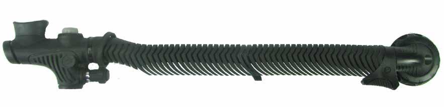

1 TECHNICAL MAINTENANCE MANUAL POWERLINE INFLATOR
2 2 CHANGE RECORD PAGE # REV. DATE TITLE OR DESCRIPTION CHANGE MADE BY 9/15/18 11/20/14 Change oral rod torque Spec to 6.5 in-lbs (0.75 Nm) Aqua Lung USA
3 Powerline Inflator Technical Maintenance Manual 3 CONTENTS COPYRIGHT NOTICE... 4 INTRODUCTION... 4 WARNINGS, CAUTIONS & NOTES... 4 SCHEDULED SERVICE... 4 GENERAL GUIDELINES... 4 GENERAL CONVENTIONS... 4 DISASSEMBLY PROCEDURES... 5 REASSEMBLY PROCEDURES... 7 FINAL TESTING TABLE 1 - TROUBLESHOOTING GUIDE TABLE 2 - RECOMMENDED TOOL LIST TABLE 3 - CHECKING SPECIFICATIONS TABLE 4 - TORQUE SPECIFICATIONS TABLE 5 - RECOMMENDED LUBRICANTS & CLEANERS PROCEDURE A - CLEANING AND LUBRICATION MAINTENANCE NOTES EXPLODED PARTS DRAWING... 19
4 4 COPYRIGHT NOTICE This manual is copyrighted, all rights reserved. It may not, in whole or in part, be copied, photocopied, reproduced, translated or reduced to any electronic medium or machine-readable form without prior consent in writing from Aqua Lung International. It may not be distributed through the internet or computer bulletin board systems without prior consent in writing from Aqua Lung International Aqua Lung America, Inc. Powerline Inflator Technical Maintenance Manual INTRODUCTION This manual provides factory prescribed procedures for the correct service and repair of the Aqua Lung or Apeks products described in this manual. It is not intended to be used as an instructional manual for untrained personnel. The procedures outlined within this manual are to be performed only by personnel who have received Factory Authorized training through an Aqua Lung or Apeks Service & Repair Seminar. If you do not completely understand all of the procedures outlined in this manual, contact Aqua Lung to speak directly with a Technical Advisor before proceeding any further. WARNINGS, CAUTIONS, & NOTES Pay special attention to information provided in warnings, cautions and notes that are accompanied by one of these symbols: WARNINGS indicate a procedure or situation that may result in serious injury or death if instructions are not followed correctly. CAUTIONS indicate any situation or technique that will result in potential damage to the product, or render the product unsafe if instructions are not followed correctly. NOTES are used to emphasize important points, tips and reminders. SCHEDULED SERVICE It is recommended that the Inflator and Over-Pressure valves should be rinsed in fresh water after each use, and should be disassembled and serviced annually. However, if at all unsure about the correct functioning of the Inflator, then it must be inspected immediately. An Official Inspection consists of: 1. Check that all parts are assembled correctly and that no parts are loose. 2. Inspect for signs of corrosion, cracks, damage to sealing surfaces and check the general condition of the inflation assemblies. 3. Inspect ribbed hose for holes or tears and confirm that it is securely clamped on both ends. GENERAL GUIDELINES 1. In order to correctly perform the procedures outlined in this manual, it is important to follow each step exactly in the order given. Read over the entire manual to become familiar with all procedures before attempting to disassemble the product in this manual, and to learn which specialty tools and replacement parts will be required. Keep the manual open beside you for reference while performing each procedure. Do not rely on memory. 2. All service and repair should be carried out in a work area specifically set up and equipped for the task. Adequate lighting, cleanliness, and easy access to all required tools are essential for an efficient repair facility. 3. As the product is disassembled, reusable components should be segregated and not allowed to intermix with nonreusable parts or parts from other units. Delicate parts, which contain critical sealing surfaces, must be protected and isolated from other parts to prevent damage during the cleaning procedure. 4. Use only genuine Aqua Lung or Apeks parts for the service of this product. DO NOT attempt to substitute an original part with another manufacturer s, regardless of any similarity in shape or size. 5. Do not attempt to reuse mandatory replacement parts under any circumstances, regardless of the amount of use the product has received since it was manufactured or last serviced. 6. When reassembling, it is important to follow every torque specification prescribed in this manual, using a calibrated torque wrench. Most parts are made of either marine brass or plastic, and can be permanently damaged by undue stress. 7. In order to make the product compatible with nitrox up to 40% O2 (EAN40), the product must be properly cleaned, lubricated and assembled using genuine Aqua Lung or Apeks replacement parts. In addition, assembly must be carried out in a clean environment using powderless, latex gloves or equivalent. For more detailed information, be sure to read Procedure A: Cleaning and Lubricating. GENERAL CONVENTIONS Unless otherwise instructed, the following terminology and techniques are assumed: 1. When instructed to remove, unscrew, or loosen a threaded part, turn the part counter-clockwise. 2. When instructed to install, screw in, or tighten a threaded part, turn the part clockwise. 3. When instructed to remove an o-ring, use the pinch method (see illustration below) if possible, or use a brass or plastic o-ring removal tool. Avoid using hardened steel picks, as they may damage the o-ring sealing surface. All o-rings that are removed are discarded and replaced with brand new o-rings. Pinch Method Press upwards on sides of o-ring to create a protrusion. Grab o-ring or insert o-ring tool at protrusion. 4. Follow FINAL TESTING instructions located in this manual. If a inflator fails any of the 4 steps it should be fully serviced. 4. The following acronyms are used throughout the manual: MP is Medium Pressure; HP is High Pressure; LP is Low Pressure. 5. Numbers in parentheses reference the key numbers on the exploded parts schematics. For example, in the statement,...remove the o-ring (7) from the crown (8)..., the number 7 is the key number to the crown o-ring.


 from the BC manifold.")
.")

 from the body (32).")
 at the buckle.")
. Remove the two o-rings (27/30) from the retainer.")
 out from one side with a pin punch or similar tool to")
5 Powerline Inflator Technical Maintenance Manual 5 DISASSEMBLY PROCEDURE CAUTION: Use only a plastic or brass o-ring removal tool when removing o-rings to prevent damage to the sealing surface. Even a small scratch across an o-ring sealing surface could result in leakage. Once an o-ring sealing surface has been damaged, the part must be replaced. DO NOT use a dental pick or any other steel instrument. NOTE: Before performing any disassembly, refer to the exploded parts drawing, which references all mandatory replacement parts. These parts must be replaced, and must not be reused under any circumstances, regardless of the age of the inflator or how much use it has received since it was last serviced. Turn the retaining collar (1) and remove the upper valve from the 1 manifold. Remove the gasket (39) from the BC manifold. 5 Using a pair of pliers, carefully grasp the tip of the QD fitting (24) and turn counter-clockwise to remove it from the body (32). Remove the o-ring (25) from the QD fitting. CAUTION: Do not fasten pliers or a wrench onto the nipple of the QD fitting. Doing so may cause permanent damage to the part requiring it s replacement. 6 Remove the inlet filter (26) from the body (32). 2 Lift off the QD fitting cover (13). Using a pair of side-cutters, carefully snip the clamp (12) at the buckle. 7 Using a 3/16" hex key, remove the valve core retainer (28) from the body (32). Remove the two o-rings (27/30) from the retainer. Pull the molded hose (9) off the inflator body (32). Press the pin 3 (16) out from one side with a pin punch or similar tool to release the cable (10). Remove QD cover (13) from molded hose. NOTE: Inspect and clean the inside clamping areas of the molded hose and the connection point on the inflator body. Firmly grasp the mouthpiece 4 (31) and twist it off the body (32). Inspect the mouthpiece for any damage and replace if needed. 8 Using a valve core tool (p/n ), gently remove the valve core (29) from the retainer (28).
, engage the pins into the hole on the")

 from the oral poppet")
 and the 14")
 from the button.")
 and pull it straight")
 and button (19)")


.")
 to fall out.")
 from the elbow (2).")
")
6 6 9 Using the large end of the T-tool (p/n 42314), engage the pins into the hole on the inflator bezel (17). Loosen and remove the assembly. Slide off the screen (23). 13 Remove the o-ring (15) from the oral poppet valve (14). Remove the oral inflator button (35) and the 14 spring (33) from the body (32). Separate the gasket (34) from the button. While holding the inflator bezel (17), grab the push rod 10 housing (20) and pull it straight away to separate the bezel. Separate the button cover (18) and button (19) from the bezel. Thoroughly inspect the button cover for any cuts or tears. 15 Using a small phillips screwdriver, remove the nut & screw from the clip (3). Remove the clip from the molded hose (9). 11 Turn the push-rod housing (20) over and allow the push-rod (22) to fall out. Remove the o-ring (21) from the housing. Separate the hose (9) from the elbow (2). Slide the collar 16 (1) off the elbow. While holding the oral inflator button (35) depressed, insert a 12 5mm hex key through the upper barrel of the body (32) and carefully turn the oral poppet valve (14) counter-clockwise to remove. 17 Pull and keep slight tension on the cable (10). Use a 3mm hex key to push in the legs of the poppet guide (7) one at a time to release.
 from the elbow (2).")


 onto poppet 1 stem (5).")
 onto poppet stem.")
, poppet stem, pull dump spring (6) and")
7 Powerline Inflator Technical Maintenance Manual 7 Pull down on the cable (10) to remove the poppet guide 18 assembly (4-8) from the elbow (2). Once the poppet guide assembly is out, remove the poppet dump valve (4). REASSEMBLY PROCEDURE NOTE: Before performing any reassembly, it is important to inspect all parts, both new and those that are being reused, to ensure that every part and component is perfectly clean and free of any dust, corrosion, or blemishes. Before dressing each o-ring with Christo- Lube, check to ensure it is clean, supple, and free of any blemish. WARNING: Use only genuine Aqua Lung/Apeks parts, subassemblies, and components whenever assembling any Aqua Lung/Apeks product. DO NOT attempt to substitute an Aqua Lung/Apeks part with another manufacturer s, regardless of any similarity in shape, size or appearance. Doing so may render the product unsafe, and could result in serious injury or death. 19 Remove the cable (10) from the inflator cable hook (8). Slide spring (6) onto poppet 1 stem (5). Insert narrow end of poppet stem into poppet guide (7). Install dump valve poppet (4) onto poppet stem. 20 Use needle nose pliers to gently grip the end of the poppet stem (5). Separate the inflator cable hook (8), poppet stem, pull dump spring (6) and poppet guide (7). 2 Compress poppet spring (6) and install the inflator cable hook (8) onto the poppet stem (5). The hook should be held at the single-looped end. THIS CONCLUDES DISASSEMBLY NOTE: Before beginning reassembly, perform parts cleaning and lubrication in accordance with Procedure A: Cleaning and Lubricating
 by first working it over 3")


 through the")

 with")

")


")
 until it is")


8 8 Install the cable (10) onto the hook (8) by first working it over 3 one end, and then spread both ends apart to work it over the other. When correctly installed, the cable should be held inside the double-looped end. 7 Install the cable (10) through the molded hose (9). Slide the molded hose onto the elbow (2). 8 Make sure to line up two notches on clip assembly (3) with grooves on elbow (2). Install the poppet assembly 4 into elbow (2). The cut-out on the poppet guide (7) faces the bottom of the elbow. 9 Tighten screw using small Phillips screwdriver. Check that clip is properly fitted. 5 Squeeze the poppet guide (7) feet together and push into elbow (2). Confirm the poppet guide is locked into place and the poppet guide feet are seated flush with the elbow. Fit the oral inflator gasket (34) over the four guides of the oral 10 inflator button (35) until it is evenly seated at the base of each guide. Set the button aside. 6 Pull on the upper cable (10) to confirm actuation of the pull dump. Install the collar (1) onto the elbow (2). 11 Install the o-ring (15) onto the oral poppet valve (14), into the groove around the base of the large end.
 inside the opening of the body.")


 through the open barrel of the inflator body (32) and")

 to a torque")
 into the small end of the push rod housing (20), and hold it")
 into its opening in the body (32), and press firmly against the button")
 over the inflator button so that it seats flush against the shoulder of the push")
 over the button cover and press down while rotating the bezel counter-clockwise")

9 Powerline Inflator Technical Maintenance Manual 9 Stand the inflator body (32) with the mouthpiece end facing 12 up, and place the large end of the oral inflator spring (33) inside the opening of the body. Place the oral inflator button (35) directly over the spring, and rotate the button as needed to align the indexing tab with the center groove of the body. Depress the oral inflator button, and hold it fully depressed. 17 Fit the o-ring (21) over the narrow end of the push rod housing (20) so that it rests flush against the seating shoulder. Slide the cylindrical screen (23) over the narrow end of the push rod housing until it rests against the base. 13 Use a 5mm hex key to guide the oral poppet valve (14) through the open barrel of the inflator body (32) and into the oral inflator button (35). Slowly turn the valve clockwise to engage the threads of the oral inflator button. Tighten further until lightly snug. Be careful to avoid cross threading. 14 Apply an in-lbs torque wrench with a 5mm hex key adapter to tighten the oral poppet valve (14) to a torque measurement of 6.5 in-lbs (0.75 Nm). Do not overtighten. 15 Insert the narrow stem of the push rod (22) into the small end of the push rod housing (20), and hold it securely in place with the stem protruding from the opposite end. 18 Insert the push rod housing (20) into its opening in the body (32), and press firmly against the button (19) to ensure the o-ring (21) seats evenly between the body (32) and the housing. 19 Fit the button cover (18) over the inflator button so that it seats flush against the shoulder of the push rod housing. Fit the inflator bezel (17) over the button cover and press down while rotating the bezel counter-clockwise until a click is felt. Then, turn the bezel clockwise to engage the threads and continue tightening by hand until finger snug. Be careful to avoid cross-threading. 16 Place the inflator button (19) inside the top of the push rod housing (20), with the opening facing down over the push rod stem. Squeeze the push rod and inflator button between thumb and forefinger to fit them securely together. CAUTION: It is important to rotate the bezel counter-clockwise, in order to properly seat the threads before tightening it into the body. Failure to correctly follow this step may cause permanent damage to the bezel and the body due to cross threading, which could result in leakage if both parts are not replaced.
.")


 onto the quick disconnect fitting (24).")


, turn the valve core clockwise to engage the threads of the")

 up the molded hose (9).")
10 10 Using the large end of the T-Tool (p/n 42314), insert the pins 20 into the two opposing holes in the inflator bezel (17). While holding the tool securely engaged, turn the bezel clockwise until it is flush with the surface of the body. DO NOT overtighten. Closely inspect the button cover (18) to ensure that it is seated evenly on all sides, and does not appear to be crimped or partially unseated. 24 Place the inlet filter (26) inside the opening for the quick disconnect fitting (24). Check to ensure that it is seated evenly below the threads. 21 Install the larger o-ring (27) onto the valve core retainer (28), in the groove below the base of the threads. Install the smaller o-ring (30) over the small end of the retainer, so that it rests against the seating shoulder. 25 Install the o-ring (25) onto the quick disconnect fitting (24). Insert the quick disconnect fitting into the body (32) and turn clockwise by hand until it is completely threaded into the body. Apply a small pair of pliers padded with neoprene or cloth to tighten the fitting until snug. "Do Not Overtighten". 22 Insert the valve core (29) with the threaded portion facing up into the valve core retainer (28). Using a valve core tool (p/n ), turn the valve core clockwise to engage the threads of the retainer. Tighten further only until it is snug while being careful to avoid crossthreading or overtightening. 26 Fit the mouthpiece (31) onto the inflator body (32), so that it is securely seated at the base. Slide the QD cover (13) up the molded hose (9). 23 Insert the narrow end of the valve core retainer (28) into the threaded opening of the body (32). Turn clockwise to engage the threads. Using a 3/16" hex key, tighten the retainer until snug or until the end of the valve retainer is flush with the surrounding surface of the body. DO NOT overtighten. 27 Insert the cable retaining pin (16) partly through one of the holes of the inflator barrel of the body (32). Pull back the molded hose (9) to expose the crimped retainer of the cable (10), and pass the retainer over the pin. Insert the pin through the opposite side of the inflator barrel, so that it is flush on both sides of the barrel.


 2 flat inside the connection manifold.")
 clockwise to engage the threads, being careful to avoid cross-threading.")


11 Powerline Inflator Technical Maintenance Manual Fit the molded hose (9) over the inflator barrel (32) until it is mated flush at the base of the barrel. Lightly fasten a clamp (12) over the ribbed hose so that it is seated evenly inside the groove near the end. Tighten the clamp and trim the excess length with diagonal side cutters. 1 FINAL TESTING WARNING: Protective eyewear must be worn at all times during testing. While holding the upper-valve secure, firmly grasp the inflator and pull it in a straight line directly away from the upper valve. Confirm the rapid exhaust valve opens. Then check the attachment points of the airway tube at both the upper valve connection and the inflator connection. If any signs of damage or decay can be detected, it is important to replace the airway tube before proceeding any further. THIS CONCLUDES REASSEMBLY OF THE POWERLINE INFLATOR Install a new gasket (39) 2 flat inside the connection manifold. Mate the upper valve directly over the manifold. Gently turn the collar (1) clockwise to engage the threads, being careful to avoid cross-threading. Hold the airway in the desired position while tightening the retaining collar by hand until snug. CAUTION: Do not use a tool to tighten the retaining collar onto the B.C. manifold. Doing so may result in over-tightening and/or crossthreading, and could cause permanent damage that will require replacement of the entire B.C. 3 Verify that the first stage regulator which the Powerline will be used with has been recently serviced and is adjusted to a stable MP of psi (9-10 bar). Attach the first stage to a cylinder filled to 3000 psi (206 bar). Connect the Powerline to the first stage via the quick disconnect MP hose. Slowly open the valve of the supply cylinder to pressurize the regulator. CAUTION: Before pressurizing the first stage, it is important to have a properly adjusted second stage attached to the first stage. This will provide a safety relief valve if the MP exceeds 145 psi (10 bar). Failure to relieve increasing MP may result in damage to the MP hose.


 NOTE: If leakage is not immediately detected, allow the B.C.")
12 12 Depress the inflator button 4 of the Powerline inflator several times to ensure that airflow is unobstructed. After releasing the button, listen carefully to ensure that the airflow has completely stopped. If internal leakage can be heard, refer to Table 1:Troubleshooting Guide and correct the problem as needed before proceeding. 5 Hold the inflator button depressed to fully inflate the B.C. until an overpressure relief valve opens to release excess pressure inside the bladder of the B.C. 7 If any leakage is heard or if the B.C. has begun to deflate within one hour, fully inflate the B.C. once again with the Powerline inflator and hold the entire B.C. submerge in fresh water for at least one minute to determine the source of leakage. During this time carefully observe the Powerline for any signs of bubble formation indicating a leak, especially around the inflator buttons and B.C. connections. If a continuous leak is detected, the Powerline must be disassembled and examined for damage or contamination of the seals and seating surfaces. (Refer to Table 1: Troubleshooting Guide, and correct as needed.) NOTE: If leakage is not immediately detected, allow the B.C. to stand for at least one hour to ensure that none exists THIS CONCLUDES THE SERVICE OF THE POWERLINE INFLATOR CAUTION: Before performing this test, confirm the B.C. has functioning over-pressure relief valves. Failure to do this could cause permanent damage to the bladder that will require replacement of the entire B.C. NOTE: The Powerline inflator does not have a built in over-pressure valve. 6 Press the deflation button briefly and then pull the rapid exhaust cable to ensure a rapid and unobstructed exhaust using both methods of deflation. Fully inflate the B.C. once again, and disconnect the Powerline from the quick disconnect hose to listen closely for any signs of leakage.
13 Powerline Inflator Technical Maintenance Manual 13 TABLE 1: TROUBLESHOOTING GUIDE SYMPTOM POSSIBLE CAUSE TREATMENT 1. MP hose (36) is obstructed 1. Clean or replace hose Restricted airflow or BC inflates slowly (with full tank, stable MP) Air does not vent when rapid exhaust valve cable is pulled Air leaks continuously from Upper-Valve when BC is inflated 2. Filter (26) is clogged or obstructed 2. Replace filter 3. Valve core (29) is clogged or corroded 3. Replace valve core 4. Dirt/salt deposits are present within the inflator assembly 1. Rapid exhaust cable (10) is not properly connected to the inflator or elbow, or is damaged 2. Incorrect rapid exhaust valve cable (10) installed (to long) 4. Flush with warm fresh water 1. Check condition and connections of cable, and correct as needed 2. Replace cable 1. Dump plug (4) is worn or damaged 1. Replace dump plug 2. Dump plug spring (6) is damaged 2. Replace spring 3. Incorrect rapid exhaust valve cable (10) installed (to short) 3. Replace cable 1. O-ring (15/21/25/27) is damaged 1. Replace faulty o-ring External air leakage from inflator 2. Inflator button cover (18) is damaged or incorrectly installed 2. Disassemble and correct as needed 3. Push rod (22) is damaged 3. Replace push rod 4. Inflator body (32) is damaged 4. Replace body 1. Valve core (29) corroded or damaged 1. Replace valve core Internal leakage from inflator 2. O-ring (27) damaged or worn 2. Replace o-ring 3. Valve core retainer (29) damaged or worn 3. Replace valve core retainer 4. Inflator body (32) is damaged 4. Replace body Cannot orally inflate the buoyance cell 1. Dirt/salt deposits are present on internal sealing surfaces 2. Internal parts of oral inflator worn or damaged 1. Flush with warm fresh water 2. Replace lower inflator assembly 3. Tear/hole in molded hose (9) 3. Replace molded hose 4. Collar (1) not tightened properly 4. Remove collar from aircell & reinstall 5. Gasket (39) is missing or damaged 5. Replace gasket NOTE: This is a partial list of possible problems and recommended treatments. For more information, refer to the second-stage troubleshooting guide, or contact Aqua Lung Technical Service Department for assistance with problems not described here CAUTION: Recommended treatments which require disassembly of the regulator must be performed during a complete overhaul, according to the prescribed procedures for scheduled, annual service. Do not attempt to perform partial service
")
14 14 TABLE 2: TOOL LIST & SERVICE KITS PART NO. DESCRIPTION APPLICATION N/A Side Cutters Removal & trimming of panduit clamps Brass O-ring Tool Kit Plastic O-ring Tool Removal of o-rings T-Tool Removing & installing bezel (17) N/A Hex Key (3/16", 5mm) Loosen/tighten/adjust parts N/A N/A N/A Torque Wrench Hex Key Adapter (5mm) Phillips Screwdriver (small) Apply torque to parts listed in Table 3: Torque Specification Apply torque to parts listed in Table 3: Torque Specification Removing and installing upper hose clip (3) N/A Pliers (small) Removing and installing QD stem (24) N/A N/A N/A N/A Needle Nose Pliers Small Punch Valve Core Tool, Dual Side Christo-Lube Magnifier with illumination Removing and installing parts Removing and installing cable pin (16) Removing and installing valve core (29) Lubrication of o-rings Sealing surface inspection N/A Ultrasonic cleaner Brass and stainless steel parts cleaning
 6.5 in-lbs (0.")
15 Powerline Inflator Technical Maintenance Manual 15 TABLE 3: CHECKING SPECIFICATIONS TEST SPECIFICATION Leak Test No Leaks Permitted TABLE 4: TORQUE SPECIFICATIONS PART # DESCRIPTION/KEY ITEM # TORQUE Oral Poppet Valve (14) 6.5 in-lbs (0.75 Nm)
16 16 TABLE 5: RECOMMENDED CLEANERS & LUBRICANTS LUBRICANT/CLEANER APPLICATION SOURCE Christo-Lube MCG 111 PerflouroLube 20/1 Lubricant for all o-rings Aqua Lung, PN , or Lubrication Technologies 310 Morton Street Jackson, OH (800) Performance Fluids Ste 101 Lomeshaye Business Park Turner Road Nelson Lancashire BBP 7DR CAUTION: Silicone rubber requires no lubrication or preservative treatment. DO NOT apply grease or spray to silicone rubber parts. Doing so may cause a chemical breakdown and premature deterioration of the material. White distilled vinegar (diluted with water) Bath for reusable stainless steel and brass parts. Household grade CAUTION: Do not use muriatic acid for the cleaning of any parts. Even if strongly diluted, muriatic acid can harm chrome plating and may leave a residue that is harmful to o-ring seals and other parts. Oxygen Compatible Solution As Per Training Promoclean TP108 Nitrox/O2 Cleaning INVENTEC PERFORMANCE CHEMICALS SA. 20, Rue de bourgogne BP SAINT-PRIEST cedex Janitol Plus JOHN LAWSON DIST. SCOTSHAW BROOK HOUSE BRANCH ROAD LOWER DARWEN LANCASHIRE BB3 0PR Liquid Dishwashing Detergent (diluted with warm water) Degreaser for brass and stainless steel parts; general cleaning solution for plastic and rubber Household grade
17 Powerline Inflator Technical Maintenance Manual 17 PROCEDURE A: CLEANING & LUBRICATING AQUA LUNG AND APEKS REGULATORS AND NITROX When it comes to issues of nitrox safety and compatibility, the concerns lie primarily with the regulator s first stage as it is subjected to high inlet pressures. High inlet pressures lead to adiabatic compression or heating of the gas. The Aqua Lung or Apeks regulator product described in this manual, when properly cleaned and assembled, is authorized for use with enriched air nitrox (EAN) that does not exceed 40% (EAN 40). It is authorized because it has undergone adiabatic compression testing and the authorized service kit components and lubricants are compatible in elevated oxygen environments. During cleaning, a mild detergent must be used to remove condensed hydrocarbons (compressor oils) from the inside passageways of the first stage. For the first stage to remain EAN40 compatible, only use hyperfiltered compressed gas (hydrocarbons < 0.1 mg/m3). Ordinary compressed breathing air (Grade E) usually does not meet this criterion. Once ordinary breathing air is used, the first stage is no longer EAN40 compatible until it is cleaned and serviced again. Although regulator second stage components are not exposed to high pressure EAN, Aqua Lung and Apeks recommend that the same cleaning procedures be followed for the complete regulator. This prevents the possibility of cross contamination and guarantees the cleanliness of the entire regulator. Cleaning Brass and Stainless Steel Parts 1. Preclean in warm, soapy water* using a soft nylon bristle brush. 2. Thoroughly clean parts in an ultrasonic cleaner filled with soapy water. If there are stubborn deposits, household white distilled vinegar (acetic acid) in an ultrasonic cleaner will work well. DO NOT place plastic, rubber, silicone or anodized aluminum parts in vinegar. 3. Remove parts from the ultrasonic cleaner and rinse with fresh water. If tap water is extremely hard, place the parts in a bath of distilled water to prevent any mineral residue. Agitate lightly, and allow to soak for 5-10 minutes. Remove and blow dry with low pressure (25 psi) filtered air, and inspect closely to ensure proper cleaning and like-new condition. Cleaning Anodized Aluminum, Plastic & Rubber Parts Anodized aluminum parts and parts made of plastic or rubber, such as box bottoms, box tops, dust caps, etc., may be soaked and cleaned in a solution of warm water mixed with mild dish soap. Use only a soft nylon toothbrush to scrub away any deposits. Rinse in fresh water and thoroughly blow dry, using low pressure filtered air. CAUTION: Do not place plastic and rubber parts in contact with acid solutions. This could alter their physical properties and cause degradation and premature breakdown. Cleaning MP Hoses (Air use Only) Follow Hose Inspection & Cleaning Guidelines for more detailed information 1. Hose fittings: Ultrasonically clean with soapy water; Use soft nylon bristle brush. If corrosion is evident, use a brass bristle brush. 2. Run water through hose if needed 3. Thoroughly rinse with fresh water 4. Blow out hose before installing CAUTION: Do not place complete hose length in contact with acid solutions. This could alter their physical properties and cause degradation and premature breakdown. Lubrication and Dressing Wear powderless, latex gloves when handling and lubricating o-rings. Keeping internal parts free from skin oils and other contaminates is important when running enriched air nitrox through a first stage. All o-rings should be lubricated with Christo-Lube MCG-111. Dress the o-rings with a very light film of grease, and remove any visible excess by running the o-ring between thumb and forefinger. Avoid applying excessive amounts of Christo-Lube grease, as this will attract particulate matter that may cause damage to the o-ring. *Soapy water is defined as household grade liquid dishwashing detergent diluted in warm water.
18 18 MAINTENANCE NOTES


19 Powerline Inflator Technical Maintenance Manual 19 POWERLINE INFLATOR Key # Part # Description Service Kit, Powerline Inflator Powerline Airway, Charcoal,Complete Powerline Airway, Black,Complete,Apeks Powerline, Lower Unit, Charcoal Collar Elbow Clip, Nut & Screw, Charcoal Clip, Nut & Screw, Black, Apeks Poppet, Dump Valve Poppet Stem Spring Poppet Guide Cable Hook Molded Hose Cable Hose Clip Clamp QD Fitting Cover Oral Valve Poppet O-ring Cable Pin Bezel Button Cover, Gray Button Push Rod Housing P O-ring (10 pk) Push Rod Filter Screen Quick Disconnect Plug w/ O-ring P O-ring (25 pk) Filter P O-ring (25 pk) Valve Retainer Valve Core P O-ring (10 pk) Mouthpiece Body, Charcoal Body, Black, Apeks Spring Gasket Oral Button w/plug MP Braided Inflator Hose, 3/8 x MP Braided Inflator Hose, 3/8 x MP Braided Inflator Hose, 3/8 x MP Braided Inflator Hose, 3/8 x P O-ring (10 pk) Valve Core Gasket (not included in Service Kit) in-lbs 0.75 Nm in-lbs 4.5 Nm
20 POWERLINE AUTHORIZED TECHNICIAN TECHNICAL MAINTENANCE MANUAL. POWERLINE INFLATOR Aqua Lung America 2340 Cousteau Court, Vista CA Rev 03/2016
POWERLINE INFLATOR with DUAL-VALVE
 TECHNICAL MAINTENANCE MANUAL POWERLINE INFLATOR with DUAL-VALVE 2 Contents COPYRIGHT NOTICE... 3 INTRODUCTION... 3 WARNINGS, CAUTIONS & NOTES... 3 SCHEDULED SERVICE... 3 GENERAL GUIDELINES... 3 GENERAL
AUTHORIZED TECHNICIAN TECHNICAL MAINTENANCE MANUAL CALYPSO FIRST STAGE
 AUTHORIZED TECHNICIAN TECHNICAL MAINTENANCE MANUAL CALYPSO FIRST STAGE Contents Copyright notice...3 Introduction...3 Warnings, Cautions, & Notes...3 Scheduled Service...3 General Guidelines...3 General
Service & Repair Manual
 Powerline Inflator (With Dual Valve) Service & Repair Manual for Authorized Sea Quest Service Centers Doc. No. 42983 1999 Sea Quest, Inc. 2 Sea Quest Powerline Service and Repair Manual Contents Introduction...
LOW PROFILE AUTO DUMP VALVE
 TECHNICAL SUPPORT LOW PROFILE AUTO DUMP VALVE MAINTENANCE MANUAL FOR AUTHORISED TECHNICIANS Document No. AP 5921 Issue 2 09/11/06 APEKS MARINE EQUIPMENT LTD, NEPTUNE WAY, BLACKBURN, LANCASHIRE. BB1 2BT
LOW PRESSURE INFLATION SYSTEM (LPIS) DRY SUIT INFLATION SYSTEM (DSIS) TECHNICAL MANUAL
 DRY SUIT INFLATION SYSTEM (DSIS) TECHNICAL MANUAL") LOW PRESSURE INFLATION SYSTEM (LPIS) DRY SUIT INFLATION SYSTEM (DSIS) TECHNICAL MANUAL Rev. 6/17 2 LPIS / DSIS Technical Manual COPYRIGHT NOTICE This manual is copyrighted, all rights reserved. It may
LOW PRESSURE INFLATION SYSTEM (LPIS) DRY SUIT INFLATION SYSTEM (DSIS) TECHNICAL MANUAL Rev. 6/17 2 LPIS / DSIS Technical Manual COPYRIGHT NOTICE This manual is copyrighted, all rights reserved. It may
DS, US, TEK3 & Extrair FIRST STAGE REGULATOR
 TECHNICAL SUPPORT DS, US, TEK3 & Extrair FIRST STAGE REGULATOR MAINTENANCE MANUAL FOR AUTHORISED TECHNICIANS Document No. AP5317 Issue 1 14/11/2006 APEKS MARINE EQUIPMENT LTD, NEPTUNE WAY, BLACKBURN, LANCASHIRE.
Gauge Consoles MAINTENANCE MANUAL FOR COMPETENT TECHNICIANS
 TECHNICAL SUPPORT Gauge Consoles MAINTENANCE MANUAL FOR COMPETENT TECHNICIANS Document No. AP 5929 Issue 1 26/11/09 APEKS MARINE EQUIPMENT LTD, NEPTUNE WAY, BLACKBURN, LANCASHIRE. BB1 2BT Tel: 0044 (0)
SERVICE MANUAL LEGEND FIRST STAGE
 SERVICE MANUAL LEGEND FIRST STAGE Copyright 2005 Aqualung France Rev. 02/2005 2 Legend First Stage Service Manual Index COPYRIGHT... 3 INTRODUCTION... 3 WARNINGS, ATTENTION, NOTE...... 3 MAINTENANCE...
SERVICE INSTRUCTIONS
 SERVICE INSTRUCTIONS GEMINI BREATHABLE INFLATOR SR9000 INTRODUCTION The instructions set forth in this document are intended to guide the experienced scuba equipment repair technician through the standard
TX SECOND STAGE REGULATOR
 TECHNICAL SUPPORT TX SECOND STAGE REGULATOR MAINTENANCE MANUAL FOR AUTHORISED TECHNICIANS Document No. AP5833 Issue 1 6/06/2006 APEKS MARINE EQUIPMENT LTD, NEPTUNE WAY, BLACKBURN, LANCASHIRE. BB1 2BT Tel:
12S 1st Stage. -Maintenance Procedure-
 12S 1st Stage -Maintenance Procedure- 1 Warning! All maintenance and repair procedures MUST be performed by a Mares authorized Service Center and/or Distributor. Therefore, the information provided below
500SE SECOND STAGE SERVICE PROCEDURE
 500SE SECOND STAGE SERVICE PROCEDURE This 500SE Service Procedure conveys a list of components and service procedures that reflect the 500SE as it was configured at the time of this writing. CONTENTS TROUBLESHOOTING...
DS, US, TEK3 & Extrair FIRST STAGE REGULATOR
 TECHNICAL SUPPORT DS, US, TEK3 & Extrair FIRST STAGE REGULATOR MAINTENANCE MANUAL FOR AUTHORISED TECHNICIANS Document No. AP5317 Issue 4 15/02/2011 APEKS MARINE EQUIPMENT LTD, NEPTUNE WAY, BLACKBURN, LANCASHIRE.
CONSHELF XIV TECHNICAL MANUAL
 CONSHELF XIV TECHNICAL MANUAL Rev. 3/17 2 Conshelf XIV Technical Manual COPYRIGHT NOTICE This manual is copyrighted, all rights reserved. It may not, in whole or in part, be copied, photocopied, reproduced,
SCUBAPRO. Balanced Power Inflator
 SCUBAPRO Balanced Power Inflator USE THIS GUIDE AS A REFERENCE WHEN SERVICING THE BALANCED POWER INFLATOR Important note: The following information is not designed to be a complete training guide for servicing
Service and Repair Manual
 II stage R2 Ice/ Special, II stage R 1 Pro DOWNSTREAM 2 nd STAGE REGULATOR Service and Repair Manual Introduction Safety Precautions...4 General Procedures, Maintenance Schedules...5 Initial Inspection
 INTRODUCTION The instructions set forth in this document are intended to guide the experienced scuba equipment repair technician through the standard service procedure for this Sherwood regulator. It is
FSR & FST FIRST STAGE REGULATOR
 TECHNICAL SUPPORT FSR & FST FIRST STAGE REGULATOR MAINTENANCE MANUAL FOR AUTHORISED TECHNICIANS Document No. AP5825 Issue 7 16/02/2011 APEKS MARINE EQUIPMENT LTD, NEPTUNE WAY, BLACKBURN, LANCASHIRE. BB1
Apeks T20 First St age Service & Repair Manual. for Authorized Sea Quest Service Centers Sea Quest, Inc.
 Apeks T20 First St age Service & Repair Manual for Authorized Sea Quest Service Centers 2000 Sea Quest, Inc. Contents Introduction... 3 Safety Precautions... 3 General Procedures... 3 Maintenance Schedules...
SECOND STAGE SERVICE GUIDE
 SECOND STAGE SERVICE GUIDE 200_08 SRB1000 INTRODUCTION The instructions set forth in this document are intended to guide the experienced scuba equipment repair technician through the standard service procedure
RG1200 Service and Repair Manual
 Dive Rite RG 1200 Regulator Service and Repair Manual Page 1 Text and Photography by Pete Nawrocky Copyright ( ) 1999-2000, Lamartek, Inc., dba Dive Rite RG1200 Service and Repair Manual First Stage.........................................
SERVICE AND REPAIR MANUAL ALTAIR OCTO PN RG300. Service & Repair Manual. Revised - 02/11
 SERVICE AND REPAIR MANUAL ALTAIR OCTO PN RG300 Service & Repair Manual Revised - 02/11 AltAir Octo Contents Section 1 - Introduction Scheduled Service... 3 EAN/ Nitrox Service... 3 Facility Requirements...
MAINTENANCE PROCEDURE FOR X 650
 MAINTENANCE PROCEDURE FOR X 650 X 650 25. juli 2005-1/6 MAINTENANCE PROCEDURE FOR X 650 2 ND STAGE WARNING: This maintenance procedure is only for appointed Scubapro technicians that completed a course
Maintenance and Repair. AirHawk II Air Mask. Second Stage Regulator. Order No.: /02 Prnt. Spec (I) MSAsafety.
 MSAsafety.") Maintenance and Repair Second Stage Regulator Order No.: 10104241/02 Prnt. Spec. 10000005389(I) MSAsafety.com WARNING! Read this manual carefully before servicing the device. The device will perform as
Maintenance and Repair Second Stage Regulator Order No.: 10104241/02 Prnt. Spec. 10000005389(I) MSAsafety.com WARNING! Read this manual carefully before servicing the device. The device will perform as
TECHNICAL TRAINING SS1
 TECHNICAL TRAINING SS1 2003 1 Limited Lifetime Warranty Atomic Aquatics warrants the SS1 safe second/inflator against defects in materials and workmanship for the lifetime of the original owner with the
SERVICE & REPAIR MANUAL H.A.B.D.
 Authorized Technician SERVICE & REPAIR MANUAL H.A.B.D. (Helicopter Aircrew Breathing Device) Rev. 02/16 2 H.A.B.D. Service & Repair Manual COPYRIGHT NOTICE This owner s manual is copyrighted, all rights
SERVICE & REPAIR MANUAL H.A.B.D.
 Authorized Technician SERVICE & REPAIR MANUAL H.A.B.D. (Helicopter Aircrew Breathing Device) REVISED 12/07 H.A.B.D. Service & Repair Manual 2 Copyright Notice This owner s manual is copyrighted, all rights
MDB TECHNICAL MANUAL. Military Buoyancy Compensator. Rev. 11/17
 MDB Military Buoyancy Compensator TECHNICAL MANUAL Rev. 11/17 2 MDB Technical Manual COPYRIGHT NOTICE This manual is copyrighted, all rights reserved. It may not, in whole or in part, be copied, photo
SERVICE AND REPAIR MANUAL SPIRIT REGULATOR PN RG100. Service & Repair Manual. Revised - 02/11
 SERVICE AND REPAIR MANUAL SPIRIT REGULATOR PN RG100 Service & Repair Manual Revised - 02/11 Spirit Regulator Contents Section 1 - Introduction Warnings, Cautions, & Notes... 3 Scheduled Service... 3 EAN/
Booster Pump PB4-60 Replacement Kits
 Booster Pump PB4-60 Replacement Kits FOR YOUR SAFETY - This product must be installed and serviced by a contractor who is licensed and qualified in pool equipment by the jurisdiction in which the product
Pay special attention to information provided in warnings, cautions and notes that are accompanied by one of these symbols:
 TABLE OF CONTENTS General Information Outlaw / Rogue Components ModLock Connectors Waistband / Shoulder Strap Assembly Aircell Assembly ModLock Connector Disassembly Waistband Extender Double Cylinder
Helicopter Aircrew Breathing Device (H.A.B.D.) User s Manual
 User s Manual") Helicopter Aircrew Breathing Device (H.A.B.D.) User s Manual Rev 02/16 2 H.A.B.D. User s Manual COPYRIGHT NOTICE This owner s manual is copyrighted, all rights reserved. It may not, in whole or in part,
Helicopter Aircrew Breathing Device (H.A.B.D.) User s Manual Rev 02/16 2 H.A.B.D. User s Manual COPYRIGHT NOTICE This owner s manual is copyrighted, all rights reserved. It may not, in whole or in part,
Pressure Dump Valve Service Kit for Series 2300 Units
 Instruction Sheet Pressure Dump Valve Service Kit for Series 00 Units. Overview The Nordson pressure dump valve is used to relieve hydraulic pressure instantly in Series 00 applicator tanks when the unit
SERVICE AND REPAIR MANUAL SEAAIR REGULATOR PN RG200. Service & Repair Manual. Revised - 02/11
 SERVICE AND REPAIR MANUAL SEAAIR REGULATOR PN RG200 Service & Repair Manual Revised - 02/11 SeaAir Regulator Contents Section 1 - Introduction Warnings, Cautions, & Notes...3 Scheduled Service...3 EAN/
Product Information News
 Product Information News MMR SECOND STAGE REGULATOR VALVE CORE MSA has changed its recommended rebuilding of the MMR Second Stage Regulator s bypass sleeve assembly during the annual inspection. Based
Contents. Stainless Steel Side Block. 1.1 Separating the Side Block. Stainless Steel Side Block Reassembly of. Assembly from the Helmet Shell
 Separating the Side Block Assembly from the Helmet Shell Contents SSB-1 SSB-3 SSB-5 SSB-5 SSB-7 1.1 Separating the Side Block Assembly from the Helmet Shell 1.2 Side Block Assembly Replacement 1.3 Defogger
APEKS TX 50 TECHNICAL MANUAL. Regulator REV 05/13
 APEKS TX 50 Regulator TECHNICAL MANUAL REV 05/13 2 TX50 Technical Manual COPYRIGHT NOTICE This manual is copyrighted, all rights reserved. It may not, in whole or in part, be copied, photocopied, reproduced,
SR2 Service Manual - Second Stage -
 SR2 Service Manual - Second Stage - 1 INTRODUCTION The instructions set forth in this document are intended to guide the experienced scuba equipment repair technician through the standard service procedure
Odyssea. non-magnetic. technical manual
 Odyssea non-magnetic technical manual 2 Odyssea Technical Manual Copyright Notice This manual is copyrighted, all rights reserved. It may not, in whole or in part, be copied, photo copied, reproduced,
CSAV. Combat Swimmer Assault Vest. Rev.05/11
 CSAV Combat Swimmer Assault Vest technical manual Rev.05/11 2 CSAV Technical Maintenance Manual COPYRIGHT NOTICE This owner s manual is copyrighted, all rights reserved. It may not, in whole or in part,
Model VR6 System. Installation, Operation & Maintenance
 Model VR6 System Installation, Operation & Maintenance General: All Archer Instruments chlorination systems are carefully designed and tested for years of safe, accurate field service. All Archer Instruments
Product Information News September 26, 2003
 Product Information News September 26, 2003 LEVER HEIGHT INSPECTION FOR FIREHAWK MMR MSA is announcing a revision to the instructions for the Firehawk MMR Second Stage Regulator as they relate to the air
THERE WHEN YOU NEED IT
 SPARE AIR SERVICE MANUAL FOR ALL MODELS 18072 Gothard Street, Huntington Beach, CA 92648 USA 800-648-DIVE P: 714-842-6566 F: 714-842-4626 www.spareair.com e-mail: info@submersiblesystems.com THERE WHEN
SEA LW & 4500 (Survival Egress Air) User's Manual
 User's Manual") SEA - 3000LW & 4500 (Survival Egress Air) User's Manual Rev. 06/17 2 SEA-3000LW & 4500 User's Manual COPYRIGHT NOTICE This user's manual is copyrighted, all rights reserved. It may not, in whole or in
SEA - 3000LW & 4500 (Survival Egress Air) User's Manual Rev. 06/17 2 SEA-3000LW & 4500 User's Manual COPYRIGHT NOTICE This user's manual is copyrighted, all rights reserved. It may not, in whole or in
SCUBAPRO Repair Guide. S600-S550 Second Stages
 SCUBAPRO Repair Guide S600-S550 Second Stages S600 Configuration A S600 Configuration B USE THIS GUIDE AS A REFERENCE WHEN SERVICING THE S600 AND S550 SECOND STAGES S550 P/N 41-047-000 FOR REPAIR OF S600-S550
Hydraulic Punch Drivers
 SERVICE MANUAL 7804SB / 7806SB Quick Draw 7704SB / 7706SB Quick Draw Flex Quick Draw Hydraulic Punch Drivers Serial Codes AHJ and YZ Read and understand all of the instructions and safety information in
Installation Troubleshooting Maintenance Instructions Installation / Start-up
 Model ZW207 Installation Troubleshooting Maintenance Instructions Installation / Start-up NOTE: Flushing of all pipe lines is to be performed to remove all debris prior to installing valve. 1. For making
Pressure Dump Valve Service Kit for Series 3000 Units
 Instruction Sheet Pressure Dump Valve Service Kit for Series 000 Units. Overview The Nordson pressure dump valve is used to relieve hydraulic pressure instantly in Series 00, 400, 500, and 700 applicator
Cleaning rod: spring steel, stainless steel or carbon fibre cleaning rod - only use a one-piece rod. Avoid using snakes.
 Telemark Biathlon Where performance and precision come together http://telemarkbiathlon.com Rifle Cleaning Date : July 19, 2013 Anschutz Rifle Manual - Click Here Izhmash 7-3 Rifle Manual - still looking
MMR Air Mask With. with Quick-Connect Hose
 MMR Air Mask With with Quick-Connect Hose Upgrade Kits P/N 10025120 Slide to Connect P/N 10050038 Slide to Connect w/ Solid Cover P/N 10038666 Push To Connect P/N 10050037 Push To Connect w/ Solid Cover
FIRST AND SECOND STAGE REGULATORS TECHNICAL SERVICE PROCEDURES
 FIRST AND SECOND STAGE REGULATORS TECHNICAL SERVICE PROCEDURES Note: These instructions and schematics are intended for use by qualified regulator repair technicians. They are intended to supplement, not
Combination Breathing Apparatus
 and Combination Breathing Apparatus ULTRAVUE FACEPIECE TAL 502 (L) Rev. 0 MSA 2005 Prnt. Spec. 10000005389 (I) Mat. 10064385 Doc. 10064385 ULTRAVUE FACEPIECE COMPONENTS Item Part No. Description 800509
ATLANTIS. Military Buoyancy Compensator TECHNICAL MANUAL
 ATLANTIS Military Buoyancy Compensator TECHNICAL MANUAL 2 Atlantis Technical Manual Copyright Notice This manual is copyrighted, all rights reserved. It may not, in whole or in part, be copied, photo copied,
Regulators repair and maintenance. XS Compact 2nd stage. January 2014 Rev XSC /3 Ed. C /14 1
 XS Compact 2nd stage January 2014 Rev XSC /3 Ed. C /14 1 XS Compact 2nd stage WARNING! This manual is intended for use by expert technicians who have already received training in equipment repairs and
PROPORTIONING VALVE. Model 150 INSTRUCTION MANUAL. March 2017 IMS Company Stafford Road
 PROPORTIONING VALVE Model 150 INSTRUCTION MANUAL March 2017 IMS Company 10373 Stafford Road Telephone: (440) 543-1615 Fax: (440) 543-1069 Email: sales@imscompany.com 1 Introduction IMS Company reserves
GORSKI G2000SS DIVING HELMET TECHNICAL MANUAL
 GORSKI G2000SS DIVING HELMET TECHNICAL MANUAL REVISION 06/11 COPYRIGHT NOTICE This manual is copyrighted, all rights reserved. It may not, in whole or in part, be copied, photocopied, reproduced, translated,
AIR SOURCE. Owner's Manual
 AIR SOURCE Owner's Manual CONTENTS INTRODUCTION... 5 WHAT IS THE AIR SOURCE?...5 GUIDELINES & LIMITATIONS... 6 DAMAGE...6 LUBRICATION...6 SAFETY PRECAUTIONS... 7 INSTALLATION... 8 INFLATION... 10 OPERATION
REGULATORS OMEGA II SECOND STAGE TROUBLE SHOOTING SYMPTOM POSSIBLE CAUSE TREATMENT
 TOUBLE SHOOTING SYMPTOM POSSIBLE CAUSE TEATMENT * Freeflow 1. Incorrectly positioned during water entry. 2. Second stage adjusted too sensitively. 3. Excessive intermediate pressure from first stage. 4.
Air Mask Low/High Pressure
 Air Mask Low/High Pressure USERS MAINTENANCE INSTRUCTIONS THIS MANUAL MUST BE CAREFULLY READ AND FOLLOWED BY ALL PERSONS WHO HAVE OR WILL HAVE THE RESPONSIBILITY FOR USING OR SERVICING THIS AIR MASK. This
GS2000. (Part Number GR050) Second Stage SERVICE & REPAIR GUIDE
 Second Stage SERVICE & REPAIR GUIDE") GS2000 (Part Number GR050) Second Stage SERVICE & REPAIR GUIDE Contents Introduction... 3 About This Manual...3 Scheduled Service... 3 EAN/ Nitrox Service... 3 Use of Warnings, Cautions, & Notes... 3 Function
GS2000 (Part Number GR050) Second Stage SERVICE & REPAIR GUIDE Contents Introduction... 3 About This Manual...3 Scheduled Service... 3 EAN/ Nitrox Service... 3 Use of Warnings, Cautions, & Notes... 3 Function
Gas Lines. Technical Manual. Sumitomo (SHI) Cryogenics of America, Inc Vultee Street Allentown, PA U.S.A.
 Cryogenics of America, Inc Vultee Street Allentown, PA U.S.A.") Gas Lines Technical Manual Sumitomo (SHI) Cryogenics of America, Inc. 1833 Vultee Street Allentown, PA 18103-4783 U.S.A. Revision F: April 2008 261320A TABLE OF CONTENTS Page DESCRIPTION...1 SPECIFICATIONS...2
Gas Lines Technical Manual Sumitomo (SHI) Cryogenics of America, Inc. 1833 Vultee Street Allentown, PA 18103-4783 U.S.A. Revision F: April 2008 261320A TABLE OF CONTENTS Page DESCRIPTION...1 SPECIFICATIONS...2
Balanced SCUBA Second Stage Regulator (P/N ) Maintenance Manual Contents
 Maintenance Manual Contents") Before Going Further Introduction Balanced SCUBA Second Stage Regulator (P/N 200-120) Maintenance Manual Contents SCBAL-1 SCBAL-1 SCBAL-1 SCBAL-2 SCBAL-2 SCBAL-2 SCBAL-2 SCBAL-2 SCBAL-3 SCBAL-3 SCBAL-3
Before Going Further Introduction Balanced SCUBA Second Stage Regulator (P/N 200-120) Maintenance Manual Contents SCBAL-1 SCBAL-1 SCBAL-1 SCBAL-2 SCBAL-2 SCBAL-2 SCBAL-2 SCBAL-2 SCBAL-3 SCBAL-3 SCBAL-3
LEAK SEALING SYSTEMS
 OPERATION MANUAL FOR LEAK SEALING SYSTEMS 04 FEB 2016 PN 22-891709 Paratech Incorporated Headquarters Paratech Europe, Branch of Paratech Inc. P.O. Box 1000, Frankfort, IL 60423 USA P.O. Box 174, 5260
SALCO PRODUCTS, INC. PRESSURE RELIEF VALVE STORAGE, INSTALLATION, OPERATING, MAINTENANCE/TESTING, AND INSPECTION INSTRUCTIONS
 STORAGE INSTRUCTIONS Until it is time to install a new or reconditioned valve on the car, the valve must be kept in its original packaging in order to protect it from dirt and damage. INSTALLATION INSTRUCTIONS
ExtendAire TM II. Intermediate Pressure Accessory Kit USER INSTRUCTIONS
 ExtendAire TM II Intermediate Pressure Accessory Kit USER INSTRUCTIONS THIS MANUAL MUST BE CAREFULLY READ AND FOLLOWED BY ALL PERSONS WHO HAVE OR WILL HAVE THE RESPONSIBILITY FOR USING OR SERVICING THIS
Operation Manual Guillotine Cutter RC-5
 Operation Manual Guillotine Cutter RC-5 Technical Specifications General Safety/Operating Instructions Using the Guillotine Cutter/Crimper Blade Change Instructions Maintenance Instructions This is a detailed
CSAV. Combat Swimmer Assault Vest
 CSAV Combat Swimmer Assault Vest technical manual 2 CSAV Technical Manual COPYRIGHT NOTICE This owner s manual is copyrighted, all rights reserved. It may not, in whole or in part, be copied, photocopied,
OCTO SRB9150 SRB9350 BRUT MAGNUM SECOND STAGES SERVICE GUIDE
 SR9952 OCTO SRB9150 SRB9350 BRUT MAGNUM SECOND STAGES SERVICE GUIDE 1 INTRODUCTION The instructions set forth in this document are intended to guide the experienced scuba equipment repair technician through
GORSKI G2000SS DIVING HELMET
 GORSKI G2000SS HELMET TECHNICAL MAINTENANCE MANUAL GORSKI G2000SS DIVING HELMET Rev. 8/12 www.aqualung.com/militaryandprofessional 2 Gorski G2000SS Diving Helmet Technical Manual COPYRIGHT NOTICE This
EASTERN ENERGY SERVICES PTE LTD. 60 Kaki Bukit Place #02-19 Eunos Tech Park Singapore, SG Singapore Telephone: Fax:
 2 Table Of Contents 1. Introduction 3 2. About this Manual 3 3. Contacting YZ Systems 3 4. Vessel Components 4 5. Specifications 5 6. Application 6 7. Theory of Operation 7 8. DuraSite Installation & Use
Balanced SCUBA Second Stage Regulator (P/N ) Contents
 Contents") Introduction (P/N 200-120) Contents SCBAL-1 SCBAL-1 SCBAL-1 SCBAL-2 SCBAL-2 SCBAL-2 SCBAL-2 SCBAL-2 SCBAL-3 SCBAL-3 SCBAL-3 SCBAL-3 SCBAL-4 1.1 Before Going Further 1.2 General Information 1.2.1 Introduction
Introduction (P/N 200-120) Contents SCBAL-1 SCBAL-1 SCBAL-1 SCBAL-2 SCBAL-2 SCBAL-2 SCBAL-2 SCBAL-2 SCBAL-3 SCBAL-3 SCBAL-3 SCBAL-3 SCBAL-4 1.1 Before Going Further 1.2 General Information 1.2.1 Introduction
R5 Tec Black DIN / Yoke 1 st Stage Service and Repair Manual
 R5 Tec Black DIN / Yoke 1 st Stage Service and Repair Manual Version 1.1, May 1, 2014 Disclaimer This document is proprietary to Scubatech Sp. z o. o. ("Scubatech") and no ownership rights are hereby transferred.
Helium-Oxygen Blender
 Helium-Oxygen Blender Service Manual Model No. PM5400 Series PM5500 Series (shown) SAVE THESE INSTRUCTIONS 300 Held Drive Tel: (+001) 610-262-6090 Northampton, PA 18067 USA Fax: (+001) 610-262-6080 www.precisionmedical.com
LRS(H)4 Pressure-Reducing Regulator User Manual
4 Pressure-Reducing Regulator User Manual") LRS(H)4 Pressure-Reducing Regulator User Manual Read the complete manual before installing and using the regulator. 2 Safe Product Selection When selecting a product, the total system design must be considered
LRS(H)4 Pressure-Reducing Regulator User Manual Read the complete manual before installing and using the regulator. 2 Safe Product Selection When selecting a product, the total system design must be considered
Welker Sampler. Model GSS-1. Installation, Operation, and Maintenance Manual
 Installation, Operation, and Maintenance Manual Welker Sampler Model GSS-1 The information in this manual has been carefully checked for accuracy and is intended to be used as a guide to operations. Correct
TECHNICAL DATA CAUTION
 Page 1 of 6 1. DESCRIPTION The Viking Model D-2 Accelerator is a quick-opening device, with an integral anti-flood assembly, used to increase the operating speed of a differential type dry pipe valve.
Training. Testor Training Manual
 Training Testor Training Manual Index Section 1 Introduction and Safety Warnings Section 2 Test Procedures Section 3 Test Hoses Section 4 Fault Location 1:1 1.1 Introduction The Dräger Testor test equipment
Santa Fe Cycles Assembly Guide Introduction
 Santa Fe Cycles Assembly Guide Introduction Congratulations on your purchase of your new Santa Fe bicycle. You have purchased a bicycle that has many features and qualities. Please take a few minutes and
CS150 CAP STAPLER OWNER S MANUAL
 Operation Revised 6/2013 www.stingerworld.com CS150 CAP STAPLER OWNER S MANUAL! Maintenance Safety Warranty PLEASE READ! This manual contains important information about product safety. WELCOME TO STINGER
Yukon. (Part Number GRXXX) First Stage SERVICE & REPAIR GUIDE
 First Stage SERVICE & REPAIR GUIDE") Yukon (Part Number GRXXX) First Stage SERVICE & REPAIR GUIDE Contents Introduction... 3 About This Manual...3 Scheduled Service... 3 EAN/ Nitrox Service... 3 Use of Warnings, Cautions, & Notes... 3 Function
Yukon (Part Number GRXXX) First Stage SERVICE & REPAIR GUIDE Contents Introduction... 3 About This Manual...3 Scheduled Service... 3 EAN/ Nitrox Service... 3 Use of Warnings, Cautions, & Notes... 3 Function
KIRBY MORGAN SUPERFLOW REGULATOR OPERATIONS AND MAINTENANCE MANUAL
 KIRBY MORGAN SUPERFLOW REGULATOR OPERATIONS AND MAINTENANCE MANUAL Manual Prepared by Dive Lab, Inc. Copyright 2003, Dive Lab, Inc. All Rights Reserved TABLE OF CONTENTS 2 SECTION 1.0 GENERAL INFORMATION
Contents. REX Regulator and Oral Nasal. 1.1 Regulator Performance Kirby Morgan Tools for the REX REX Regulator
 Regulator Performance Contents REX-1 REX-1 REX-1 REX-2 REX-2 REX-3 REX-3 REX-4 REX-5 REX-6 REX-6 1.1 Regulator Performance 1.1.1 REX Regulator 1.1.2 Kirby Morgan Tools for the REX Regulator 1.2 REX Demand
Assembly Drawing: W-311B-A01, or as applicable Parts List: W-311B-A01-1, or as applicable Special Tools: , , &
 REDQ Regulators Model 411B Barstock Design Powreactor Dome Regulator OPERATION AND MAINTENANCE Contents Scope..............................1 Installation..........................1 General Description....................1
!!!! SERVICE MANUAL PRESSURE POT 2 GALLON. Service Manual: LT Washington St 931 Progress Ave., #7
 EXEL North America, Inc. EXEL Industrial Canada, Inc. 1310 Washington St 931 Progress Ave., #7 West Chicago, IL 60185 Scarborough ONT, M1G 3V5 Ph : (800) 573 5554 Ph : (800) 450 0655 Fx : (800) 664 1511
Pressure Relief Valve Instruction Manual
 CVR3-M0_062017 Pressure Relief Valve Instruction Manual MODEL: CVR3 SFA Companies 10939 N. Pomona Ave. Kansas City, MO 64153 Tel: 888-332-6419 * Fax: 816-448-2142 E-mail: sales@bvahydraulics.com Website:
GX300 REGULATOR FOR THE AQUA LUNG G3000SS DIVING HELMET MAINTENANCE MANUAL FOR AUTHORISED TECHNICIANS
 Home TECHNICAL SUPPORT GX300 REGULATOR FOR THE AQUA LUNG G3000SS DIVING HELMET MAINTENANCE MANUAL FOR AUTHORISED TECHNICIANS Document No. AP2548 Issue 4 19/07/2015 APEKS MARINE EQUIPMENT LTD, NEPTUNE WAY,
Installation, Operation and Maintenance Manual for Back Pressure Regulator
 Installation, Operation and Maintenance Manual for Back Pressure Regulator Model 8860 2009 Groth Corporation IOM-8860 Rev. B 12541 Ref. ID: 95565 Page 2 of 13 Table of Contents I. INTRODUCTION 3 II. DESIGN
APP pumps APP and APP Disassembling and assembling
 Service guide APP pumps APP 11-13 and APP 16-22 Disassembling and assembling hpp.danfoss.com Table of Contents Contents 1. Introduction... 2 2. Disassembling the pump... 3 3. Assembling the pump... 6 4.
8. Carefully layout all the parts of the reservoir setup and clean any dirt, grime or dust from the parts. ( image 8 ) 8
 8") INSTRUCTIONS TO SERVICE AMADAXTREME SHOCKS 2.0 REMOTE RES AUSTRALIAN VERSION PART 1 - SERVICE THE RESERVOIR 1.Prior to cleaning the shock check for any leaks or signs of damage to the res, lines, bushes
INSTRUCTIONS TO SERVICE AMADAXTREME SHOCKS 2.0 REMOTE RES AUSTRALIAN VERSION PART 1 - SERVICE THE RESERVOIR 1.Prior to cleaning the shock check for any leaks or signs of damage to the res, lines, bushes
Survival Egress Air (SEA) User's Manual LV2
 User's Manual LV2") Survival Egress Air (SEA) User's Manual LV2 MK Rev. 12/10 2 SEA USER'S MANUAL Copyright Notice This owner s manual is copyrighted, all rights reserved. It may not, in whole or in part, be copied, photocopied,
Survival Egress Air (SEA) User's Manual LV2 MK Rev. 12/10 2 SEA USER'S MANUAL Copyright Notice This owner s manual is copyrighted, all rights reserved. It may not, in whole or in part, be copied, photocopied,
Installation, Operation, and Maintenance Manual
 Installation, Operation, and Maintenance Manual Welker Probe Instrument Regulator Model The information in this manual has been carefully checked for accuracy and is intended to be used as a guide for
AIR DRIVE ROLL FEED CARTON STAPLER MODEL: H-1031 MANUAL
 AIR DRIVE ROLL FEED CARTON STAPLER MODEL: H-1031 MANUAL WARNING Before operating this stapler familiarize yourself with the safety warnings and instructions in this manual. Keep these instructions with
Installation of Your SprayMaster System
 Installation of Your SprayMaster System 1. At the installation site, remove all equipment from the corrugated box and the polyethylene drum and replace the drum lid. Check the picture to identify each
310 SERIES TILT-TO-LOAD ROTATOR. The Specialist In Drum Handling Equipment
 OPERATOR S MANUAL FOR MORSE TILT-TO-LOAD DRUM ROTATOR SAFETY INFORMATION: While Morse Manufacturing Co. drum handling equipment is engineered for safety and efficiency, a high degree of responsibility
CBP LPU- 40 Flotation Collar User s Manual
 CBP LPU- 40 Flotation Collar User s Manual January 2015 Capewell Aerial Systems LLC 4298 JEB Stuart Hwy Meadows of Dan, VA 24120 www.aerialmachineandtool.com Phone: 276-952-2006 FAX: 276-952-2231 Table
Air-Oxygen Blender. Service Manual. Model No. PM5200 Series PM5300 Series (shown)
") Service Manual Model No. PM5200 Series PM5300 Series (shown) SAVE THESE INSTRUCTIONS 300 Held Drive Tel: (+001) 610-262-6090 Northampton, PA 18067 USA Fax: (+001) 610-262-6080 www.precisionmedical.com
Service Manual Model No. PM5200 Series PM5300 Series (shown) SAVE THESE INSTRUCTIONS 300 Held Drive Tel: (+001) 610-262-6090 Northampton, PA 18067 USA Fax: (+001) 610-262-6080 www.precisionmedical.com
RB70 Automatic Diluent Valve Maintenance Manual. Version 1.1 November 2006 Written by Tino de Rijk. Page 1 of 23
 RB70 Automatic Diluent Valve Maintenance Manual Version 1.1 November 2006 Written by Tino de Rijk Page 1 of 23 Table of Contents 1. Introduction... 3 2. ADV diagram and parts list (Pre June 2006)... 4
WELLS JOHNSON HIGH VOLUME CANISTERS
 WELLS JOHNSON HIGH VOLUME CANISTERS USER MANUAL DISASSEMBLY OF HARVESTING CANISTERS Please follow the instructions provided to disassemble 5L, 3L, 2L, and 1L, 250mL and 500mL harvesting canisters. 1. Unscrew
SERVICE MANUAL SALAMANDER BROILERS RADIANT AND INFRARED 36RB 36IRB VULCAN C36RB C36IRB WOLF
 SERVICE MANUAL SALAMANDER BROILERS RADIANT AND INFRARED VULCAN 36RB 36IRB WOLF C36RB C36IRB This Manual is prepared for the use of trained Vulcan Service Technicians and should not be used by those not
KIRBY MORGAN DEEP SEA DIVING HELMETS ALL MODELS OVERHAUL, MAINTENANCE, AND INSPECTION CHECKLIST APPENDIX A
 KIRBY MORGAN DEEP SEA DIVING HELMETS ALL MODELS OVERHAUL, MAINTENANCE, AND INSPECTION CHECKLIST APPENDIX A2.1 05-23-17 THIS INSPECTION AND MAINTENANCE SHOULD BE PERFORMED AT LEAST ANNUALLY AND AS DICTATED