METEOR Microsystems Engineering and Technology
|
|
|
- Theodore Fletcher
- 6 years ago
- Views:
Transcription

1 METEOR Microsystems Engineering and Technology for the Exploration of Outer Regions Senior Design Project 06006: Design and Testing of a Small Scale Rocket for Pico-Satellite Launching. Dr. Jeffrey Kozak Dr. Dorin Patru Project Advisor Project Advisor David Dale John Chambers Chris Hibbard Mechanical Engineer Mechanical Engineer Mechanical Engineer Project Manager Jeff Nielsen Jessica LaFond Anthony Fanitzi Mechanical Engineer Mechanical Engineer Mechanical Engineer Daniel Craig Mechanical Engineer Brad Addona Mechanical Engineer
2 Table of Contents 1. Introduction / Motivation 1 2. Organization / Team Breakdown Senior Design Project Scope Team Breakdown Project Planning 8 3. Literature Review Introduction Similar Projects / Missions Pegasus Minotaur Designs AspireSpace University of Colorado at Boulder Air Launched Flight Trajectories Hybrid Rocket Introduction / Benefits of Hybrid Rocket Propellants Performance Predictions Fuel Chamber Feed System Ignition System Injector Exit Nozzle Federal Specifications Needs Assessment Performance Goals Design Goals Secondary Goals Specifications / Success Qualifiers Concept Development / Feasibility Hybrid Engine Propellant Selection Solid Fuel Selection Liquid Oxidizer Selection Fuel Grain / Propellant Sizing Propellant Mass Regression Rate Mass Flow Rate / Fuel Grain Sizing Fuel Chamber Intended for Ground Testing Basic Configuration Obtaining Required Data Injector Design Basic Concept Machining / Assembly Ignition System Feed System Basics Oxidizer Tank Filling Nitrogen Tank Loading 44 Senior Design P06006 Page i
3 Oxidizer Properties Valves Exit Nozzle Nozzle Shaping Nozzle Materials Nozzle Attachment Test Stand Introduction Basic Configuration Safety Considerations Built in Redundancies Paper Design Introduction Aluminum Truss System Satellite Base Plate Thrust / Injector Plate Satellite Release Mechanism Satellite Containment Hybrid Engine Configuration Engineering Analysis / Design Validation FEA Analysis Introduction Test Stand Analysis Materials Loading and Restraints Study Properties Stress Results Strain Results Displacement Results Design Check Results Conclusion Combustion Chamber Analysis Materials Loading and Restraints Study Properties Stress Results Strain Results Displacement Results Design Check Results Conclusion Rocket Calculations Rocket Sizing and Thrust Calculations Givens and Assumptions Mass Estimation Regression Rate Sizing Oxidizer Mass Flow Rate Exit Nozzle Shaping Given and Assumptions Area Sizing 81 Senior Design P06006 Page ii
4 Exit Velocity Senior Design II Deliverables Primary Deliverables at End of SD II Secondary Objectives Future Plans Time Table Propellant Testing Molding Combustion Ignition Testing Glow Plug Ignition Pyrotechnic Ignition Data Acquisition Component Testing Feed System / Oxidizer Flow Combustion Chamber Tests Test Stand Materials Testing the Rocket Test Results Budget 88 References 89 Appendices 91 Appendix 1 - Drawing Package Appendix 2 - Bill of Materials Appendix 3 - Gantt Chart SD I Appendix 4 - Risk Assessment Appendix 5 - Objective Trees Appendix 6 - Timeline SD II Appendix 7 - Rocket Calculations Appendix 8 - Regression Rates Appendix 9 - Rocket Nozzle Calculations Appendix 10 - Feed System Schematic Appendix 11 - Ni-Chrome Wire Temperature Properties Appendix 12 - Safety Report Appendix 13 - MSDS Sheets Senior Design P06006 Page iii
5 List of Figures Figure 1 Launch System Block Diagram.4 Figure 2 Typical Mission Profile.5 Figure 3 Work Breakdown Structure...8 Figure 4 Typical Pegasus Mission Profile.11 Figure 5 Minuteman Launch Vehicle Configuration.12 Figure 6 Cross-sectional View of Test Chamber...31 Figure 7 Swirling Nozzle...34 Figure 8 Spray Pattern for Various Gasification Injection Gas Ratios..35 Figure 9 Initial Injector Concept Drawing.36 Figure 10 Final Injector Concept Cross-section 37 Figure 11 Pure Oxygen Ignition System Schematic..38 Figure 12 Glow Plug..39 Figure 13 Glow Plug Ignition System Schematic..40 Figure 14 Pyrotechnic / Ni-Chrome Igniter...41 Figure 15 Pyrotechnic Ignition System Schematic 43 Figure 16 Oxidizer / Nitrogen Tank Fill Schematic..44 Figure 17 Concept for Testing Within Test Cell...52 Figure 18 Horizontal Test Stand Concept.54 Figure 19 Preliminary Drawing of Chosen Test Stand Design.55 Figure 20 Front and Isometric View of Aluminum Truss System, Satellite Base Plate, Thrust Plate and Satellite Release Mechanism Assembly.58 Figure 21 Pressurized Satellite Release Mechanism.60 Figure 22 Pico-Satellite Containment and Release Schematic..62 Figure 23 Hybrid Rocket Configuration 63 Figure 24 Stress Distribution on Test Beam..67 Figure 25 Strain Distribution on Test Beam..68 Figure 26 Displacement of Test Beam...69 Figure 27 Yield Factor of Safety Distribution on Test Beam 70 Figure 28 Ultimate Factor of Safety Distribution on Test Beam...71 Figure 29 Stress Distribution on Test Chamber.74 Figure 30 Strain Distribution on Test Chamber.75 Figure 31 Dislocations of Test Chamber...76 Figure 32 Cross Sectional View of Yield Factors of Safety in Test Chamber..77 Figure 33 Cross Sectional View of Ultimate Factors of Safety in Test Chamber.78 Senior Design P06006 Page iv
6 List of Tables Table 1 Experimentally Determined Correlation Parameters 16 Table 2 Weighted Method Analysis of Hybrid Engine.24 Table 3 QFD Analysis of Hybrid Engine..25 Table 4 Pugh Analysis of Solid Fuel Propellants..27 Table 5 Correlation Parameter Table Regression Rates.29 Table 6 Pugh Analysis of Oxidizer Injection Methods..36 Table 7 Pugh Analysis of Ignition Systems...38 Table 8 Pressure of Nitrous Oxide Based on Temperature [15] 45 Table 9 Control Valve Sizing Calculation.48 Table 10 Injector Orifice Sizing Calculation.49 Table 11 Pugh Analysis of Rocket Test stands...53 Table 12 Test Stand Assembly Parts.64 Table 13 Material Properties of AISI 1020 Steel...65 Table 14 Material Properties of 4140 Annealed Steel...65 Table 15 FEA Analysis Mesh Information 66 Table 16 FEA Analysis Solver Information..66 Table 17 Location of Maximum and Minimum Stress on Test Beam.. 67 Table 18 Location of Maximum and Minimum Strain on Test Beam...68 Table 19 Location of Maximum and Minimum Displacement on Test Beam..69 Table 20 Materials Used in Test Chamber 72 Table 21 Material Properties of AISI 304 Stainless Steel.72 Table 22 FEA Analysis Mesh Information of Test Chamber 73 Table 23 FEA Analysis Solver Information of Test Chamber..73 Table 24 Location of Maximum and Minimum Stress on Test Chamber.74 Table 25 Location of Maximum and Minimum Strain on Test Chamber.75 Table 26 Location of Maximum and Minimum Displacements on Test Chamber...76 Senior Design P06006 Page v
7 Nomenclature Acronyms: METEOR: Microsystems Engineering & Technology for the Exploration of Outer Regions LEO: Low Earth Orbit DAQ: Data Acquisition MEMS: Micro-Electro-Mechanical Systems NASA: National Aeronautics and Space Administration OSCAR: Orbiting Satellite Carrying Amateur Radio RIT: Rochester Institute of Technology START: Strategic Arms Reduction Talks HTPB: Hydroxy-terminated Polybutadiene (Solid rocket fuel) PMMA: Polymethyl Methacrylate (Solid rocket fuel) AGI: Analytical Graphics Inc. STK: Satellite Tool Kit NC lacquer: Nitrocellulose lacquer FAA: Federal Aviation Administration MIL: Military standard prefix O 2 : Oxygen F 2 O: Oxygen Difluoride H 2 O 2 : Hydrogen Peroxide N 2 O: Nitrous Oxide SAE: Society of Automotive Engineers EDM: Electron Discharge Machining BP: Black Powder NH 4 ClO 4 : Ammonium Perchlorate C-D: Converging-diverging TODOR: A flow software program FOS: Factor of Safety FEA: Finite Element Analysis Variables: *All units are in Metric and can be converted to English if desired. I sp is specific impulse [sec] v total is total velocity required to achieve low earth orbit (LEO) [m/s] m L is payload mass (mass of the satellite) [kg] m s is structural mass of the rocket [kg] m elec is mass of the electronics in the rocket [kg] d i is the inner diameter of the circular fuel grain [m] d 0 is the outside diameter of the fuel grain [m] L is the total length of the fuel grain [m] ρ HTPB is density of solid fuel grain HTPB [kg/m3] g is the acceleration of gravity [m/s2] Senior Design P06006 Page vi
8 v e,v e is exhaust velocity of the rocket [m/s] Δv is the change in velocity of the rocket [m/s] N is the number of stages of the rocket [--] m 0 is the initial total mass of the rocket [kg] m 1 is the final total mass of the rocket [kg] m p is the total propellant mass [kg] E a is activation energy [kj/mol] A is the Arrhenius preexponential constant [mm/s] T s is the surface temperature of the fuel grain [K] R is the universal gas constant [J/(mol-K)] M is molecular weight of HTPB [kg/mol] r is the solid propellant regression rate [mm/s] V HTPB is the volume of HTPB burned in 1 second [m 3 ] m& HTPB is the approximate mass flow rate of HTPB [kg/s] m HTPB is the total mass of HTPB [kg] t is the amount of time [sec] t b is the amount of time for the fuel to be completely burned [sec] m& ox is the oxidizer mass flow rate [kg/s] G o is the oxidizer mass flux [kg/m 2 -s] x is axial location in the fuel grain [m] k is the gas absorption coefficient [(m-mpa) -1 ] p is the pressure [MPa] h is the port height between fuel slabs [m] n,m,k,c 1,C 2 are all parameters developed by Chiavirini for HTPB m& is total mass flow rate of the propellant [kg/s] p e is exit pressure [Pa] p a is ambient pressure [Pa] A e is exit area of the nozzle [m 2 ] τ is thrust [N] C d is Orifice Coefficient A o is Orifice Area [m 2 ] ρ is Fluid Density [kg/m 3 ] ΔP is Pressure Drop Across Orifice [Pa] m f is total fuel burned [kg] T 0 is stagnation temperature [K] P 0 is stagnation pressure [Pa] γ is the ratio of specific heats T t is nozzle temperature [K] P t is nozzle pressure [Pa] M gas is the molecular weight of the exiting gasses [kg/kmol] A t is throat area [m 2 ] D t is throat diameter [m] M e is exit Mach number Senior Design P06006 Page vii
9 About the METEOR Rocket Preliminary Design Report The following preliminary design report details the process our design team took to develop, evaluate and select the overall design concepts to meet our objectives outlined at the conclusion of this paper. The report begins with an introduction to the history of and the motivation behind the METEOR (Microsystems Engineering & Technology for the Exploration of Outer Regions) project here on RIT s campus. A description of the scope of our portion of this bold mission will follow describing the organization and breakdown of our approach to solving our objectives. The next section of our paper is a brief description of the elaborate literature review our team conducted in order to come up to speed on current technologies and similar projects. With a foundation of knowledge established, the report then discusses the needs assessment and outlines the goals and desirables that our team will accomplish by the end of Senior Design II. After establishing our design goals the paper goes on to discuss the specifications and success qualifiers that we need to achieve in order to prove that we have successfully completed our design and performance goals. After discussing the team organization and breakdown of the approach to solving the problems faced by our team the paper focuses on the heart of our concept development and design work. In depth conversation on concept development and the feasibility of each major design portion of our project is outlined in Section 6 of our paper. After much discussion on concepts, a summary of our final design and validation for our choices is given. This portion is then followed by a description of our plans for Senior Design II and where we plan to take our project over the next three months. 1. Introduction / Motivation A brief scenario taking place in today s world A small group of intelligent and innovative young engineers have been working together for the past couple years putting in their limited time and hearty effort to develop a small satellite with Micro-Electro-Mechanical Systems (MEMS) technology. The intention of this satellite is to better understand the effects of pollution in our outer atmosphere and potential risks that we may be headed for collectively as a human race. Making the satellite on such a small scale allows the engineers to construct several Senior Design P06006 Page 1
10 satellites with the intention to examine many different orbit inclinations at different locations around the world. They have put in years of hard work to develop reliable technology and are finally ready to test their theories and try to improve the understanding of our world. The team then takes their satellite to industry, to NASA, to anybody that has the capability of reaching space and gives them a well thought out and thorough presentation on the validation of their work. All the institutions are thoroughly impressed and are onboard with their ideas, however, and unfortunately they do not have the capability to launch a satellite so small; or it would cost the team upwards of $500,000 to 1 million dollars to reserve a flight onboard a rocket designed to carry cargo 100 times its size. Another option presented to them is to wait 2-3 years and they could possibly reserve a spot on a prototype air force rocket, but of course there is no guarantee that it will be delivered successfully to lower earth s orbit. Until they finally discover a program that has been running on RIT s college campus in Western NY for a number of years lead by generations of groups of undergraduate students with similar amateur ambitions. They are able to launch their satellite to any inclination at about 1/10 the cost they would have paid, and as frequently as once a month if they wish. Their aspirations are realized and their research will go on to help scientists better understand exactly which chemicals are causing damage to our ozone. Historical Background Barely four years after the first American satellite was launched, on December 12 th 1961, the first Orbiting Satellite Carrying Amateur Radio, OSCAR I, was successfully launched and orbited the earth for 21 days. OSCAR I was launched piggyback, as a secondary payload on an Air Force rocket. It carried a 144 MHz beacon and weighed only 4.5 kg [1]. Over the last half a century there has been unprecedented advances in technology, in both space travel and miniaturization of technological devices. Contradictory to expectations, the cost of space travel has essentially remained the same, effectively making non-for profit launched satellites have to continue to hitch hike their way to space as secondary missions aboard expensive government rockets. This is where project Senior Design P06006 Page 2
11 METEOR is basing their reasoning for pursuing such a mission and providing a means for the academic world to reach outer-space cheaply and efficiently. What is a Pico-Satellite? A Pico-Satellite is a satellite with a weight less than 1 kg or about 2 pounds. Such a satellite can incorporate a beacon transmitter, or a transponder, and/or a video camera, or any other miniaturized scientific instrument which would fit within the specified weight limit. With current and future advances in MEMS technology it appears that these small scale satellites may be capable of performing operations once designated for much larger and more expensive satellites and launch missions. Current Options for Pico-Satellite Launch Current launch vehicles are designed to carry payloads from 100 to 6000 kg to various orbits. Orbital Sciences Inc. offers an air-launched rocket, Pegasus, which is designed to carry a payload with a minimum weight of 285 kg to lower earth s orbit (~160 km to 400 km) [2]. The project Cubesat [3], lead by CalPoly and Stanford Universities, uses a mother satellite to carry several Pico Satellites. After the mother satellite reaches the desired orbit it releases the individual Pico Satellites which then function on their own. Although the satellites weigh less then 1 kg each the cost for such a mission is $80,000. In addition the typical wait time to get aboard this mission is 3-5 years, based on the completion of each of the individual satellites. More than 40 different high school and university teams worldwide are building satellites for this project and that number is growing. In rare instances teams are lucky enough to reserve a piggy back spot as a secondary payload aboard a governmental test flight. In these cases the flight cost is actually free, but obtaining the rights to join these missions is along process and almost never works out for small amateur groups. Description of Project METEOR The METEOR project is currently in its initial phase, which consists of designing a platform capable of reaching an altitude of about 80,000 ft utilizing helium filled, highaltitude balloons. This platform will eventually be the launching point for future space Senior Design P06006 Page 3
12 bound missions. The design team is working on the program through RIT s multidisciplinary capstone design project and is composed of 5th year Electrical and Mechanical engineering students who are enrolled in senior design. The proposed launch configuration is pictured in Figure 1 Launch System Block Diagram (not to scale). Current balloons can rise above 30,000 m and float for extended periods of time, from hours to days, with payloads as heavy as 1000 kg [4]. The idea of an air launched rocket materialized in the early 90s with Orbital Sciences first aircraft launched Pegasus rocket. The idea of a balloon based launch is not new either, but to date has never been successfully completed. This flight pattern is not feasible for satellites or payloads on the order of 100 kg or more, however launching a kg rocket with a 1-5 kg satellite is within the realm of possibilities. A generic mission profile is illustrated in Figure 2 Typical Mission Profile. The balloon and its payload are launched and reach rocket launch altitude after approximately one hour. Fig. 1 Launch System Block Diagram: (1) Balloon (2) After the platform passively stabilizes, the rocket Tether (3) Parachute (4) is turned and oriented in the right direction. Once Stabilization Tethers (5) Launch Platform (6) Rocket this is achieved, ignition of the first stage occurs Suspension Lines (7) Rocket - and the rocket leaves the platform. Orientation Satellite accuracy of the rocket at the time of ignition can be within +/- 3 degrees, as the rocket guidance system should be able to correct later for the difference. Thereafter, the sequence of events is similar to any conventional rocket launch. The platform is recoverable via the parachute tether located between the balloon and platform, while the rocket stages are expendable. Senior Design P06006 Page 4
13 Why Choose METEOR Over Other Technologies? The proposed launch system has the following advantages: No need for ground infrastructure, except for an approximately seven person mobile launch control unit, which can be located in the back of a van Launch location is only limited by safety range issues over populated areas Launching from such altitudes virtually eliminates atmospheric drag during the phase of powered flight; the density of air above 80,000 feet is less that 1% that on the surface of the earth Maximum dynamic pressure will be very low, resulting in a more relaxed structural design; further supported by the fact that the low weight of the payload will cause less vibration and g-force issues Weather conditions do not affect the phase of powered flight to orbit Rocket motors operate in a virtual vacuum at all times; thus exit nozzles can be of fixed optimized dimensions for highest efficiency Launch frequency can be as often as once per month Fig. 2 Typical Mission Profile Senior Design P06006 Page 5
14 Current Situation of Project METEOR at RIT A past Senior Design team has completed the basic design, and built a prototype for the platform designed to carry a rocket to 80,000 feet. Since that time two successful launches have been completed with smaller balloons attached. The platform reached an altitude of approximately 30,000 feet before it returned safely to the ground, the entire time taking live video feed and keeping contact with the team on the ground. Another Senior Design Team which completed Senior Design I in the fall 2005 and will be entering Senior Design II at the same time as our team in the spring 2006, has updated and improved the platform. They have added several electronic devices and intend to give the platform the capability to orient itself prior to launching the rocket. Currently there are also two EE graduate students that are working on inertial and navigation systems for the rocket and updating the technologies that will be placed on the Pico Satellite. Both of these students are putting in extensive time and effort to ensure that the rocket and satellite will perform correctly during and after the powered flight stage. Our team is intended to lay the ground work for future teams that will focus on the rocket design portion of the METEOR project. We intend to gain experience with the propellants used and provide enough information that future teams can accurately size and predict the nature of the rocket launch vehicle. Senior Design P06006 Page 6
15 2. Organization / Team Breakdown 2.1 Senior Design Project Scope Based on preliminary work done by Dr. Patru and other students in order for a rocket to carrying a 1 kg satellite to lower earth s orbit (LEO) and obtain a velocity of 7600 m/s it is expected that it will need four stages making the following assumptions [5]: A redundant weight of 10%; structural weight is only 10% of the total weight of the rocket Isp = 235 sec A loss of 1600 m/s due to drag loss, gravity loss, maneuvering and launch window allowance Over the next couple of years the METEOR project aspires to complete successful suborbital launches with single stage rockets, then making the transition to putting a multistaged rocket into LEO. The scope of our project includes ground testing hybrid rocket propellants and obtaining as much experience and data as possible in order for future teams to properly estimate performance and the size of future rockets. We are also responsible for a conceptual paper design of the upper stage of this rocket, and develop a manner to contain and release a Pico Satellite into orbit. Excluded from this paper design are navigational controls and thrust vectoring which are being examined by current graduate students on campus. Much of our paper design is dependant on the data we are able to collect by testing a prototype hybrid rocket on the ground, therefore much of the material selection and sizing procedures may be limited by the time frame allotted to our group. Senior Design P06006 Page 7
16 2.2 Team Breakdown Understanding hybrid rocket engines and predicting there performance required a lot of background research and investigation into similar projects. Also establishing a safe and accurate testing procedure has required extensive investigation by our team. In order to tackle a project with such a wide scope we have broken the team up into the following focus areas: METEOR Rocket Design P06006 Hybrid Engine Lead / Exit Nozzle Design Propellant Selection / Data Acquisition Feed System / Test Set-up Ignition / Materials FEA / Paper Design Test Stand / Test Procedure Project Manager / Safety Issues John Chambers Chris Hibbard & Jessica LaFond Brad Addona Dan Craig Anthony Fanitzi Jeff Nielsen David Dale Fig. 3 Work Breakdown Structure While this figure illustrates the leader in each area of research, decisions on overall system design are made as a group and evaluated with the Pugh method. Additionally it should be noted that while the above individuals are the experts on the specific assignments, responsibilities will change throughout the progression of the project as work load dictates. Furthermore, communication will remain open between all members as to better facilitate the synergy of components in the overall system design. 2.3 Project Planning Based on work completed by David Dale in Design Project Management in the fall of 2005, a tentative and malleable Gantt Chart was created in order to give a timeline and short term goals for the team (Appendix 3 Gantt Chart). The team has adhered to the schedule laid before them as well as can be expected, which has allowed us to confidently present to you, the reader, our design. Senior Design P06006 Page 8
17 In addition to the Gantt Chart a Risk Assessment was performed in order for our team to gauge exactly what could be accomplished in Senior Design I and II (Appendix 4 Risk Assessment). The different aspects of our design were weighed against four main criteria (1) Resource Feasibility, (2) Economic Feasibility, (3) Schedule Feasibility, and (4) Technological Feasibility. Senior Design P06006 Page 9

18 3. Literature Review 3.1 Introduction With the team structure established and a tentative timeline before us the first step our team needed to take was to conduct a comprehensive literature search to better understand current technologies and establish a good base of knowledge in the specific areas of our design. The focus of our search can be broken down into the following sections: similar projects, hybrid rocketry, test stands and data acquisition, feed system, materials, and federal specifications. The following sections outline our findings. 3.2 Similar Projects / Missions Pegasus Considering that Orbital Sciences Inc. was the first to successfully complete an air Fig. 4 Typical Pegasus Mission Profile launched flight to orbit by way of the Pegasus rocket we decided to find out much information on their chosen flight patterns and methods of achieving desirable orbital Senior Design P06006 Page 10
19 altitudes and velocities. The most useful document we could find on Pegasus was the Pegasus Users Guide [2] which gave detailed descriptions of the capabilities and typical missions that are completed by Pegasus for its customers. Figure 4 illustrates a typical Pegasus mission profile. In addition to reviewing the Pegasus User s Guide we found several other papers that reference the Pegasus rocket. One in particular introduced us to some possible scaling factors for the Pegasus rocket based on smaller payload sizes [6]. In this downsizing process, the fraction of mass for each stage to total vehicle mass is maintained, and the mass of each component is determined by using a scale factor that follows a cubic scaling law. This law infers that (for the same average density) the ratio of scaled-down mass to full-size mass is given by the cube of the scale factor; (e.g. if the scale factor is one-half, the mass ratio is one-eighth). But because it is unlikely that the avionics and the attitude control hardware can be scaled in the same manner, there would have to be some adjustments made to the downsized payload to compensate Minotaur Designs Looking for similar projects in the academic field we came across a design team from the University of Texas at Austin, which completed a design report titled Converting the Minuteman Missile into a Small Satellite Launch System [7]. The design team devised a method to convert 450 Minuteman II Intercontinental Ballistic Missiles that had been recently taken out of service as part of the Strategic Arms Reduction Talks (START) peace treaties between the United States and the Ex-Soviet Union, into launch vehicles for small satellites. These missiles are still on a much larger scale than we would like to achieve, but this paper gave us much insight into how to contain and release satellites safely into orbit. I would strongly suggest for future teams to refer to this paper, especially pertaining to staging release and structural considerations. Figure 5 illustrates the configuration of the Minuteman Launch Vehicle. Senior Design P06006 Page 11
20 Fig. 5 Minuteman Launch Vehicle Configuration AspireSpace While conducting a search for hybrid engines our team came across a group of engineers, scientists and entrepreneurs who, in their spare time, build and operate small sounding rockets. The team calls themselves AspireSpace [8]. AspireSpace is based in the United Kingdom, and their main goal is to revamp the English space program and bring young students into their organization. The paper principally covers the development of AspireSpace s first hybrid rocket engine, the H2, operating on Nitrous Oxide and Polyethylene it had an impulse of up to 1800Ns and a thrust of 600N. This paper outlined some of the basics behind hybrid rocket technology and gave us some insight into methods used to test hybrid rockets. Our team is pursuing connection to AspireSpace and I would recommend future teams to attempt to keep a dialog with this group and try to absorb as much information as possible from them, as they too began as a novice group of engineers University of Colorado at Boulder Near the end of Senior Design I our team came across a technical paper prepared by Otto Krauss, a student at University of Colorado, who worked with a group of Senior Design P06006 Page 12
21 aerospace engineers on a similar design project to ours [9]. Their project mission is similar to our METEOR project, its title is MaCH-SR1 which aims at building a sounding rocket to deliver a 10-lb payload to the edge of space, about 125 km above the earth s surface. They have chosen a single stage Nitrous Oxide / HTPB hybrid engine rocket to achieve this goal. This paper focuses on the design and test firing of a lab-scale model of their rocket and the results they obtained. Many of the design components and materials they selected are coincidently similar to many of the decisions we made, which will be explained more thoroughly in the Concept Development portion of this paper. Going through this paper we have come up with some good ideas to how to test various components of our design prior to actually assembling and firing our rocket. Also, many of the references they used will be examined more in depth Air Launched Flight Trajectories One paper used by the team to get an understanding of some typical flight trajectories and velocities associated with them was Optimal Ascent Trajectory for Efficient Air Launch into Orbit by Frederick Boltz [10]. This paper discusses three main types of trajectory to achieve LEO altitude and velocity; however, the two optimal trajectories required so much travel that our mobile control unit may not be able to keep radio contact with the rocket throughout the duration of powered flight. The team was also referred to a computer program called STK (Satellite Tool Kit), distributed by Analytical Graphics Inc. (AGI), a free version can be obtained by visiting their website, [11]. Examination of this software package was completed by Chris and Jessica, based on what the free version was capable of it was determined that we needed to purchase a license for the professional version with a missile trajectory package add on. When all was said and done we were looking at a licensing fee over $25,000, which is far beyond the scope of our budget. Based on this we decided to do preliminary calculations based on information we obtained from rocket propulsion textbooks [12]. Senior Design P06006 Page 13
22 3.3 Hybrid Rocket Introduction / Benefits of Hybrid Rocket During the summer quarter of 2005 a fellow student at RIT, Jeffery Cappola, conducted independent research on different methods to power a small scale rocket [13]. Based on his work and previous investigations completed by Dr. Patru [5] the obvious choice for rocket propulsion based on safety and convenience is a hybrid rocket engine. Other methods include pure solid or liquid propellants. Liquid propellant engines use both liquid oxidizer and liquid fuel such as liquid oxygen and liquid hydrogen stored in separate tanks and mixed together during the combustion process. Liquid rocket propellants are extremely volatile and exposure to high heats can cause explosions and dangerous situations. Solid rocket engines are sometimes unpredictable and do not have the capability to be throttled or shut off. Choosing a hybrid engine allows us to compensate for the negative safety issues associated with both solid and liquid rocket engines Propellants Our team has relied on the work done by Jeffery Cappola and several of his references in determining which propellants to consider for our hybrid rocket; Dr. Kozak was his faculty advisor for this work and supported its validity. Jeff came to the conclusion the HTPB and PMMA are the two most promising solid fuels and he went as far to suggest PMMA to possibly be a better option. These two propellants were determined to be the most promising because of their availability, environmental friendliness, ease of molding or manufacturing, and experimental data available from similar projects. Our decision making process is elaborated more in the concept development phase of the paper. For a liquid oxidizer it was obvious that Nitrous Oxide is the clear choice because of safety and storability issues associated with more volatile oxidizers such as liquid oxygen Performance Predictions Thrust and mass equations are fairly basic and can be found in almost any propulsion resource. To size a rocket, regression rate of the solid fuel must be known; Senior Design P06006 Page 14
23 and this is no simple task. There are limited resources available in this particular area of rocketry. Regression rate is difficult to estimate without experimental data; however, initial estimates can be made based on equations and correlation parameters developed by previous scientists. The equation used to calculate thrust, seen below, was found in a book called Mechanics and Thermodynamics of Propulsion [14]. τ = m& v + e ( p e p a ) A e m& is total mass flow rate of the propellant v e is exit velocity from the nozzle p e is exit pressure p a is ambient pressure A e is exit area of the nozzle Tsiolvolsky s rocket equation was found in the same book, and can be seen below: m Δv = v ln 0 e m 1 Δv is the change in velocity of the rocket v e is the exit velocity of the rocket m 1 is the final total mass of the rocket, which includes the payload mass, structural mass, and electrical mass component m 0 is the initial total mass of the rocket, which is the final total mass plus propellant mass Knowing the change in velocity one wants to achieve, the exit velocity of the rocket, and the total final mass of the rocket allows the propellant mass to be found. To size the HTPB fuel grain, regression rate must be known. Experiments on HTPB regression in a cylindrical fuel grain with a central circular port were conducted by Chiaverini and published in a paper named Regression Rate Behavior of Hybrid Rocket Solid Fuel [15]. Using this data, he developed a regression rate equation based on correlation parameters, motor pressure, oxidizer mass flux, and axial location. n m C2 r = C1 G0 x 1 n n 1 1 n n 1 G0 x G0 x kph C 2 kph ( e ) + exp ( e ) r is instantaneous regression rate of the solid fuel [mm/s] G o is the oxidizer mass flux [kg/m 2 -s] x is axial location [m] Senior Design P06006 Page 15
24 k is the gas absorption coefficient [(m-mpa) -1 ] p is the pressure [MPa] h is the port height between fuel slabs [m] n,m,k,c,c 1 2 are all parameters developed by Chiaverini whose values are given in the table below, specifically for a mixture of 96% HTPB and 4% Ultra-Fine Activated Aluminum (UFAL) Correlation Parameter Table Parameter 96% HTPB / 4% UFAL Units C n/a 1 C n/a n 0.63 n/a m n/a K (m*mpa) -1 Table 1 - Experimentally Determined Correlation Parameters In the Regression-Rate and Heat-Transfer Correlations for Hybrid Rocket Combustion paper by Martin J. Chiaverini, Kenneth K. Kuo, Arie Peretz, and George C. Harting at The Pennsylvania State University, Pennsylvania 1680 [16], another one of the regression rate equations we used in our analysis was found. This paper showed an analysis of a hybrid rocket motor that used solid propellant, and how the regression rate was obtained for this engine. The regression equation that they experimentally found is shown as: r = Aexp( E a / R T u s ) The parameters used in this equation include E a as the activation energy (kcal/mol), R u as the universal gas constant (kcal/kg-k), T s as the surface temperature, and A as the Arrhenius pre-exponential constant (mm/s). Their test engine included two opposing fuel slabs with an oxidizer flow rate of 530 kg/m 2. They used both real-time, X-ray radiography and ultrasonic pulse-echo systems to deduce the local, instantaneous solid-fuel regression rates. Pressure transducers provided the motor pressure history along the motor port. The regression rates were found using video images of the pyrolysis process, with micro thermocouples showing the surface temperature. This group found the equation parameters using their test results by correlating the regression rate and the surface temperature. They then plugged these parameters into Senior Design P06006 Page 16
25 the pyrolysis law, which is the above equation, where the surface temperature was greater than 722 K. This method was shown in this paper to be valid for HTPB hybrid engines Fuel Chamber Some of the basics for the configuration and different components of the solid fuel chamber were examined from multiple papers, one in particular, A Preliminary Design Code for Hybrid Rockets, Werthman, W.L. was exceptionally useful in coming up with a base design [17]. This paper introduced us to the basic idea of how the engine works, along with the idea of pre and post combustion chambers. Using theses chambers with no fuel grain allows for a more uniform flow and more predictable thrust. Teamed up with papers of similar projects we were able to come up with the basic configuration elaborated on in Section Several papers were used to design based on optimal conditions inside the chamber [18] [19]. We discovered that, optimally, the hybrid rocket solid fuel chamber should operate at around 550 psi, and the turbulent boundary layer that results over the fuel grain, along with the solid fuel s evaporation, will keep some of the high temperatures away from the surface of the walls and fuel grain. 3.4 Feed System The basic schematic for our feed system was taken from a labscale hybrid rocket tested at University of Arkansas at Little Rocket with similar intentions to our ground test [20]. The main objectives of the feed system is to supply the fuel chamber with oxidizer but also to ensure that no hot gases are able to flow back into the tanks. The schematic we are modeling after also uses a pure nitrogen purge system to shut of the combustion process by flushing out any oxygen that may be in the chamber. To predict the flow rates and pressure drops through the system we referred to Rocket Propulsion Elements: 7 th Edition, Sutton [12]. This book was also used when trying to predict the performance of our hybrid rocket engine combustion process. Predicting the pressure drops across the different valves and components of the feed system allowed us to ensure that we can obtain the desired pressure drop across the injector to get a well atomized oxidizer flow into the chamber. Senior Design P06006 Page 17
26 To locate many of the valves and components of our feed system we relied on McMasterCarr.com for many of the basic components and GlobalSpecs.com to search for some of the more specialized components. Brad Addona was primarily responsible for the feed system, he has worked for a company, ValveTech, which specializes in aerospace valves for some time and we have used that as a resource for common information and guidance also. ValveTech was also generous enough to donate some solenoid valves that will be used in our feed system. Further Investigation One important thing to note is that the feed system we have designed is intended for ground testing only. For the feed system that will be used on the actual rocket much lighter, smaller, more specialized, and much more expensive valves will need to be used to cut back on redundant weight. In addition we have not been able to locate an electronically controlled throttling valve which can change the flow rate over time, which would be highly desirable for the actual rocket to obtain constant oxidizer to fuel ratios throughout the combustion process. List of Companies Used for Components: McMaster Carr o Needle Valves o Check Valves o Tubing o Pipe Connection Components o Mechanical Pressure Gauges Omega o Pressure Transducers CoAx o Solenoid Valve ValveTech o Solenoid Valve (donated) AeroCon o Oxidizer Tanks Senior Design P06006 Page 18
27 3.5 Ignition System When performing an initial concept design as a team we agreed to use a propane type of ignition system, filling the chamber with propane prior to firing a spark plug and introducing the flow of Nitrous Oxide to the chamber. After further investigation it became apparent to the team that because of the lack of oxygen in outer space this type of system would not work at all. This sparked a more thorough literature search to determine other more reliable methods to ignite our hybrid engine. Once again we resorted to looking at previous work done [21, 22] and also looked into methods that are used in basic solid propellant Estes model rocket engines [23]. One of the most common methods of ignition is similar to our propane idea except that you would fill the chamber with pure oxygen rather than propane. Our team has decided to shy away from using pure oxygen because of its potential hazards and corrosive properties. Using pure oxygen would greatly increase the risk to the students and faculty facilitating the ground test of our hybrid rocket. One of the more promising methods but still requires further investigation is using a glow plug or the like to pre-heat the Nitrous Oxide before it enters the chamber effectively disassociation the nitrogen and oxygen for easy ignition. Another method that is used for solid propellant motors is the use of pyrogens and Ni-Chrome wires. Essentially you supply a current to the Ni-Chrome wire which heats up considerably igniting NC lacquer or a similar pyrogen which has been coated around the wire. In order to ensure that the pyrogen burns long enough to separate and burn the oxidizer we would surround the NC lacquer with an Ammonium Perchlorate / HTPB combination. Ammonium Perchlorate is a solid oxidizer that is able to burn in oxygen deprived environments, its burn temperatures are high enough to disassociate the oxidizer and it burns slow enough to ensure that there is the necessary amount of time to ignite our rocket. Further investigations of these methods are outlined in Section Injector The injector serves multiple purposes, its main objective is to reliably deliver oxidizer into the solid fuel chamber in order to stimulate the combustion process, but a secondary purpose of the injector is to atomize the oxidizer flow as much as possible. Senior Design P06006 Page 19
28 Making the particle size of the Nitrous Oxide as it enters the fuel chamber as small as possible increases the rate of disassociation of the oxygen and nitrogen which ensures no wasted oxidizer and more predictable thrust [24]. Based on designs that have been experimentally proven to improve this asset of the injector we decided to look at three different designs: a swirling nozzle [25], a shower head nozzle, and using a technique called gasification [24]. 3.7 Exit Nozzle Designing the exit nozzle is one of the most critical portions of a rocket design, but in most respects it is a rather straight forward process. Information regarding this process can easily be found in Fluid Mechanics and Aerodynamics textbooks [14, 26]. The basic concept is to run the hot gases through a converging subsonic nozzle until the flow reaches mach 1 at the throat area. From there you send the fluid through a diverging supersonic nozzle. Using the Method of Characteristics to ensure isentropic flow further increases the effectiveness of your nozzle. 3.8 Federal Specifications In order to have the proper permission to test a hybrid rocket we need to consider and abide by any local and federal regulations that pertain to this type of test. We have located two different resources that we are basing this assessment on. The first is based on FAA regulations [27] and the second according to MIL specs [28] which are commonly used in industry. To further gain permission we have completed a safety review report that we have provided to facilities management to gain permission to test our rocket on campus, see Appendix 12. Senior Design P06006 Page 20
29 4. Needs Assessment Our team being the first design group of the second phase of the METEOR project, the rocket design phase, we needed to properly assess what should be done in order for following teams to be successful. Our project being a very research intensive project made it difficult to properly predict exactly what could be completed in 20 weeks, for both the team and our mentors. Based on the original proposal and discussions we had with our sponsors the team decided on the following goals and objectives. 4.1 Performance Goals Hybrid engine must meet predicted performance requirements to carry a 1 kg satellite to lower earth s orbit Upper stage must be able to safely house, transport and release a Pico Satellite Team must establish a safe means for ground testing the rocket Gain as much knowledge and experience with propellants as possible 4.2 Design Goals Hybrid engine must be reliable and predictable when firing Team must design a safe and useful test stand to collect data Secure a location on campus to complete ground testing Choose propellants and all components of a test fuel chamber 4.3 Secondary Goals Structural design paper on the final stage of the four stage rocket Choose a flight pattern and trajectory to achieve lower earth s orbit Devise a means of thrust vectoring to control attitude Design stage separation mechanical device Senior Design P06006 Page 21
30 5. Specifications / Success Qualifiers After conducting some research and meeting with our sponsors the team was able to determine exactly what specifications we needed to achieve in order for our design to be considered successful. The following is what we determined: The redundant structural weight (empty weight) needs to be less the 15% of the total weight, for our paper design Rocket engine must be able to achieve a change in velocity of Δv = 2300 m/s Determine the optimum oxidizer to fuel (O:F) ratio for maximum thrust Obtain enough temperature and pressure data to properly design a fuel chamber for the paper design Structural design of upper stage must be able to withstand 30 g s Ignition system must properly work 100% of attempted fires Be able to measure thrust in ground test with a 1% resolution factor Senior Design P06006 Page 22
31 6. Concept Development / Feasibility 6.1 Hybrid Engine Because the many of the design objectives behind our project are focused around the hybrid rocket engine and its performance the team put in a considerable amount of effort to analyze the importance of the different aspects of a hybrid engine. We chose to use a weighted method analysis to determine which of the customer requirements carried the most importance towards our design; the results are shown in Table 2. We used the following customer requirements in our analysis: Customer Requirements: Reach Lower Earth Orbit (LEO) Weight Requirements Satellite Safety (acceleration) Safety During Testing Cost Propellant Availability Examining these results the team was able to determine that the safety during testing was the most important requirement not only to our sponsors but also for ourselves. Using this information we then applied it to a QFD analysis to get an understanding of which specification or metric was the most important to ensure a successful design. We used the following specifications to qualify a successful design. The results from the QFD analysis can be seen in Table 3. Hybrid Engine Specifications: Specific Impulse, Isp (sec) Mass Flow Rate (kg/sec) Empty Weight (kg) Chamber Pressure (Pa) Extra Solid Propellant for Insulation Force Produced (N) Senior Design P06006 Page 23
32 Total Impulse (N-s) Burn Time, t b (sec) Propellant Density Propellant Selection Pairwise Comparison: Place an "R" if the row is more important. Place a "C" if the column is more important Reach Low Earth Orbit (LEO) Weight Requirement Satellite Safety (acceleration) Safety During Testing Cost Propellant Availability Row Total Column Total Row + Column Total Relative Weight Reach Low Earth Orbit (LEO) r r c r r % Weight Requirement c c r r % Satellite Safety (acceleration) c r r % Safety During Testing r r % Cost c % Propellant Availability % Column Total % Table 2 - Weighted Method Analysis of Hybrid Engine Senior Design P06006 Page 24
33 1. DESIGN OBJECTIVE Design a hybrid rocket engine capable of containing and realeasing a 1kg satellite into low-earth orbit (LEO). Rocket will launch from a platform suspended at 100,000 ft above earth's surface. <== 3. RELATIVE IMPORTANCE* Specific Imulse (sec) 2. CUSTOMER REQUIREMENTS 1 Reach Low Earth Orbit (LEO) Weight Requirement Satellite Safety (acceleration) Safety During Testing Cost Propellant Availability ABSOLUTE IMPORTANCE 9. RELATIVE IMPORTANCE 10. TARGET SPECIFICATIONS 11. RISK EVALUATION 12. ASSESSENT OF COMPETITOR'S OR EXISTING DESIGN Mass Flow Rate (kg/s) Empty Weight (kg) Chamber Pressure Extra Solid Propellant for Insulation Force Produced (N) Total Impulse (N-s) Burn Time (t b) Propellant Density Propellant Selection * 10 = ABSOLUTELY ESSENTIAL, 7 = VERY IMPORTANT, 5 = MODERATLY IMPORTANT, 3 = NOT VERY IMPORTANT, 1 = UNIMPORTANT Table 3 - QFD Analysis of Hybrid Engine Conclusions Based on the QFD analysis completed on the hybrid rocket engine it became apparent that the amount of thrust and total impulse were the most important specifications to look at. Close behind them was the propellant selection process, which in retrospect we realized ultimately determines what kind of thrust and impulse we are able to create. With our team focused on propellant choices based on thrust and impulse, and the customer requirement of safety for testing in the forefront of our minds we went forward on the hybrid engine design. Senior Design P06006 Page 25
34 6.1.1 Propellant Selection Solid Fuel Selection Based on our literature search the team was looking two different types of safe to handle, readily available, and environmentally friendly solid propellants. One is Hydroxyl Terminated Poly-Butadiene (HTPB), similar to tire rubber, and another being Poly-Methyl Methacrylate (PMMA), which is essentially an acrylic Plexiglas material. Both of these materials had negatives and benefits in different areas so we decided to use a pugh analysis to determine which of the two to go forward with. Table 4 illustrates the pugh analysis we conducted, based on this analysis we determined that HTPB is a better option because of its cheap cost and its ability to be cured into any desired mold we construct. It should be noted from Table 4 that the normalized scores are very close and that future teams may want to look into testing PMMA verse HTPB experimentally. The main advantage of PMMA is its higher density which would allow for a smaller fuel chamber which in turn would lower the redundant weight of the rocket Liquid Oxidizer Selection The biggest determining factor when selecting a liquid oxidizer is the safety and storability of the material. Possible oxidizers include liquid Oxygen (O 2 ), Oxygen Difluoride (F2O), Hydrogen Peroxide (H2O 2), Nitrous Oxide (N2O) plus many, many more [13]. When safety and environmental factors were incorporated the obvious choice became Nitrous Oxide. Nitrous Oxide is considered a non-combustible (below 300 o C), non-hazardous material see Appendix 13 for the MSDS and Hazmat information for Nitrous Oxide. The Nitrous Oxide and HTPB combination is non-combustible unless temperatures above 300 o C are introduced, at which point the nitrogen and oxygen disassociate allowing for the oxygen to burn with the HTPB [29]. Essentially this means that we could run Nitrous Oxide through our fuel chamber and would not have any combustion unless we turn on our ignition system. Senior Design P06006 Page 26
35 Evaluate each additional concept against the baseline, score each attribute as: 1 = much worse than baseline concept 2 = worse than baseline 3 = same as baseline 4 = better than baseline 5= much better than baseline Ground Testing Motor TEA/Temperature Analysis Cost Availability Specific Impulse Mass Flow Rate - % burn to % expulsed Force Produced Propellant Burn Temperature Chamber Pressure Density of Propellant Strength to Weight Propellant Safety Propellant System Simplicity Rocket Body Material PMMA (Poly-Methyl Methacrylate) HTPB (Hydroxyl Terminated Poly-Butadiene) Mean Score Normalized Score 91.3% 100.0% Table 4 - Pugh Analysis of Solid Fuel Propellants Senior Design P06006 Page 27
36 6.1.2 Fuel Grain / Propellant Sizing Propellant Mass In order for our four stage rocket to reach lower earth orbit, calculations needed to be done regarding how much solid propellant was needed, and the velocity needed to reach the proper altitude. The propellant diameter, thickness, and length were found using the equations shown in Appendix 7. To begin these calculations an exit velocity had to be found, along with a total velocity using Tsiolkovsky s basic rocket equation [14]: Δv = ve m ln 0 m 1 mo is the initial total mass of the rocket m 1 is the final total mass of the rocket v e is the rocket s exhaust velocity v is the rocket s change in velocity This essentially tells us the maximum rocket velocity change that can be achieved by expelling a known amount of mass (m -m ) at a known velocity. o 1 The mass of the propellant was the first dimension of the propellant we found. By using the specific heat and gravity we found the exit velocity of stage four of our rocket to be 2,300 m/s. This velocity times each of our four stages gives a total velocity that needs to be achieved of 7,600 m/s, which is adjusted for gravitational and drag effects, resulting in a final total burnout velocity of 9,200 m/s. This number used in conjunction with our four stages resulted in the rocket s change in velocity to be 2,300 m/s per stage. After finding the total velocity, the masses were calculated using three different parts of the rocket to make up the total mass. These three parts included the payload mass of 1 kg satellite, a structural mass of 0.75 kg (estimated using a redundant weight of 15%), and an electrical component mass of 0.3 kg. When theses masses were added up they gave a total mass of 2.05 kg. By using the above rocket equation, plugging in the exit velocity, velocity change, and the total mass, an initial mass of the rocket was found to be kg. By subtracting the initial mass of the rocket from the total mass, a propellant mass was found to be kg. Senior Design P06006 Page 28
37 Regression Rate The next step was to use regression rate analysis that will later be used to find the diameter of the solid propellant. The regression rate equation (as shown below) that was found from extensive research in a paper by Chiaverini [16], was used to find an estimate of the regression rate for the last stage of our four stage rocket: n m C2 r = C1 G0 x 1 n n 1 1 n n 1 G0 x G0 x kph C 2 kph ( e ) + exp ( e ) r is the regression rate of the solid fuel [mm/s] G o is the oxidizer mass flux [kg/m 2 -s] x is axial location [m] k is the gas absorption coefficient [(m-mpa) -1 ] p is the pressure [MPa] h is the port height between fuel slabs [m] n,m,k,c,c 1 2 are all parameters developed by Chiaverini whose values are given in the table below, specifically for a mixture of 96% HTPB and 4% Ultra-Fine Activated Aluminum (UFAL) Correlation Parameter Table Parameter 96% HTPB / 4% UFAL Units C n/a 1 C n/a n 0.63 n/a m n/a k (m*mpa) -1 Table 5 - Correlation Parameter Table - Regression Rates This equation was placed into a spreadsheet and analyzed, see Appendix 8. However, there was some difficulty and error in using this particular regression rate equation. Further research was done; and a paper by the same individual, Chiaverini, showed another, simpler regression rate equation: Ea r = A exp R Ts E a is activation energy and is given as kj/mol A is the Arrhenius pre-exponential constant, given as mm/s Senior Design P06006 Page 29
38 T is the surface temperature of the fuel grain [K] s R is the universal gas constant which is equal to J/(mol-K) r is the solid propellant regression rate [mm/s] This equation was also put into a spreadsheet, Appendix 8, and resulted in a regression rate of mm/s. This number was a closer match to the regression rates that had been found in research papers. The exact regression rate can not be calculated until testing of the solid propellants has been completed. Due to the non-exact nature of this calculation, the regression rate we decided to use is 1 mm/s. This adjustment should put us in a range of having slightly extra fuel should our theoretical regression rate be slightly off due to human calculation error Mass Flow Rate / Fuel Grain Sizing After the regression rate was found, the next step was finding the mass flow rate. First the assumption of L/D = 10 and a 0.03 m inner diameter was made, which is accurate with other theoretic calculations we ran across. An outer diameter was calculated using the regression rate, a burn time of one second, and the inner diameter. The outer diameter after one second was found to be m, which was used in conjunction with the inner diameter and length to find the volume of HTPB. The volume of HTPB was then multiplied by the density of the HTPB to give the mass flow rate after one second for our solid propellant of kg/s. Using an oxidizer-to-fuel ratio of 8:1, the mass for HTPB was calculated. By taking 1/9 (due to the ratio) of the fuel mass that was calculated earlier, the HTPB mass came out to be kg. By placing the mass of HTPB over the mass flow rate after one second of HTPB, the burn time was calculated to be 14.4 seconds. Finally, a back calculation was done to find an outer diameter for 14.4 seconds. This was done by adding to the inner diameter the burn time multiplied by the regression rate multiplied by two for each side of the solid propellant. The resulting outer diameter came out to be m. We increased this outer diameter so that we could have extra fuel to insulate the combustion chamber walls due to the heat that the combustion chamber will produce. Also extra fuel was used to allow standard pipe sizes for the combustion chamber to be used in our design. Senior Design P06006 Page 30

39 An oxidizer flow rate was calculated as shown in the Appendix 4 using the remaining 8/9 ratio of fuel over the burn time, resulting in kg/s of oxidizer. Results of solid propellant calculations: Inner Diameter = 0.03 m Outer Diameter = m Length = 0.3 m Weight = kg Fuel Chamber Intended for Ground Testing Basic Configuration Figure 6 shows a cross-sectional view of the test chamber and identifies all the major components. After the oxidizer enters the chamber through the injector it enters a pre-combustion chamber. The purpose of the pre-combustion chamber is to ensure the disassociation of the nitrogen and oxygen and to further atomize the particle size of the nitrous oxide before it reaches the fuel grain. Injector Test Chamber Wall Fuel Grain Exit Nozzle Garolite Laminated Ceramic Snap Ring Fig. 6 Cross Sectional View of Fuel Chamber As seen in Figure 6 we have decided to go with a simple cylindrical port fuel grain. The amount of thrust a hybrid rocket is able to produce is dependent on the surface Senior Design P06006 Page 31
40 area that the fuel grain and oxidizer are interacting. With this in mind making a star pattern or a multi-port fuel grain would help to improve thrust. But because of the simplicity of the mold and potential danger of fuel grain separation prior to burning we have chosen a cylindrical pattern for the fuel grain. The post combustion chamber is intended to help make the flow more uniform as it enters the nozzle. This will in turn generate a more predictable and steady exit plume which translates into a more predictable and steady thrust produced by our engine. Because of the extreme heat we are expecting from the combustion process a Garolite Laminated Ceramic will be inserted to line the walls of the pre and post-combustion chambers. Extra solid fuel will be used to insulate the walls over the length of the fuel grain. The last component to be inserted into the fuel chamber is our graphite exit nozzle. A Snap Ring will be inserted to hold all of these components into place at the back end of the exit nozzle. The injector plate is held on to the front portion of our chamber by eight, SAE Grad 2, ¼-20 bolts Obtaining Required Data The fuel chamber must not only safely house all of the components that we need inside to fire a hybrid engine, but it must also allow us to collect the necessary data we need to predict what is occurring inside the chamber during firing. The team needs to collect temperature and pressure readings from inside the chamber in order to properly predict what materials and dimensions they need for a fuel chamber that would be used in the actual METEOR rocket. Because of redundant weight issues this chamber would need to have a low factor of safety and be able to withstand the volatile environment that can be expected from the combustion process. All of this means that the team needs to collect accurate, time dependant data throughout the firing of the rocket. Pressure Measurements The team initially went on the hunt for thermocouples and pressure transducers that could possible withstand such high temperatures. This search concluded after quickly realizing that within our budget and time constraints that this was not possible. Senior Design P06006 Page 32
41 After talking to a few different people in industry we were suggested the idea of a listening tube in order to collect pressure data. The idea of the tube is to effectively allow the gases from the chamber cool before coming in contact with the pressure transducer. The idea is simple, attach extended tubes to the chamber through a port hole in the side of the chamber, and collect the static pressure safely. However there are many complications associated with this process which the team needs to reconcile prior to using this method to collect pressure data. The listening tube that would be directly tapped into the flow would need to be able to withstand the worst case pressure scenarios. In addition at the interface of the tube and the chamber it would need to be able to withstand the extreme temperatures associated with the combustion process. Furthermore in order for the tube to be directly tapped into the flow we would need to drill a hole through the ceramic liner we are using to protect our chamber. All of these problems need to be cured prior to the team being able to collect pressure data. One other complication with using listening tubes, but is easily taken care of is the time delay seen by the transducer from the real time pressure in the chamber. A simple test can be conducted to back out this delay and use that to correlate our collected data. By simply assembling the tube, not connected to the chamber, with the pressure transducer, one would need to fill the chamber with some set pressure. After reaching a steady pressure in the tube start your data acquisition and at some recorded time release the pressure from the tube. The difference from the time you release the pressure to the time that that is reflected in your data is you time delay associated with your listening tube. Temperature Measurements In order to take temperature measurements in the chamber the team has decided to embed the thermocouples into the exterior of the chamber and use heat transfer equations to back out the information. Before this can be successfully done tests will need to be conducted on the chamber, ceramic liners, and solid fuel in order to obtain their heat transfer coefficients. This method will allow us to not only back out what is going on inside the chamber, but also estimate the temperatures that would be seen outside the ceramic liners and fuel grain where the actual fuel chamber interface is located. Senior Design P06006 Page 33
42 6.1.4 Injector Design Basic Concept The injector serves multiple purposes, it main objective is to reliably deliver oxidizer into the solid fuel chamber in order to stimulate the combustion process, but a secondary purpose of the injector is to atomize the oxidizer flow as much as possible. Making the particle size of the Nitrous Oxide as it enters the fuel chamber as small as possible increases the rate of disassociation of the oxygen and nitrogen which ensures no wasted oxidizer and more predictable thrust [24]. Based on designs that have been experimentally proven to improve this asset of the nozzle we decided to look at three different designs: a swirling nozzle [25], a shower head nozzle, and using a technique called gasification [24]. All three of these methods serve the same purpose is decreasing the particle size of the oxidizer. The swirling nozzle sends the flow into a vortex motion prior to reaching the combustion point of the chamber increasing the mixing and decreasing the particle size, see Figure 7 for a schematic of a basic swirling nozzle design. It can be seen from these diagrams that actually machining this part is no easy process and would require us to outsource this part to a specialized machine shop. This would greatly increase the cost for our injector. The method of gasification is a relatively new science that is just beginning to be examined in the scientific realm. Figure 8 illustrate the effects of gasification and its benefits. The basic idea of gasification is to Fig. 7 Swirling Nozzle introduce an inert gas into the flow of oxidizer as it enters the injector which will greatly decrease the particle size as can be seen in Figure 8. The down side of this method is that it introduces more redundant Senior Design P06006 Page 34

43 structures to the system which would increase the paper design weight of the actual rocket. Fig. 8 Spray Pattern for Various Gasification Injection Gas Ratios The third method that we considered was a showerhead type of design. We figured this was a simple, cheaper method of trying to accomplish the same goals of the previous two types of injectors. We completed a pugh analysis on these designs, Table 6, to weigh the different factors of each design. From these results the team decided to go forward with the showerhead design. Senior Design P06006 Page 35
44 Pugh Analysis: Injector Design Showerhead Swirling Nozzle Gasification Manufacturability System Complexity Cost Effectiveness Weight Total points: Table 6 - Pugh Analysis of Oxidizer Injection Methods Machining / Assembly In order to machine our injector we will use the same method as the University of Colorado used to machine their similar injector, Electron Discharge Machining (EDM). This method of machining allows us to make holes through the injector on the order of.025 or less. The smaller the size of the holes and the greater the number, allows us to increase the atomization of the oxidizer which is our design intention. Fig. 9 Initial Injector Concept Drawing Senior Design P06006 Page 36

45 Initially we designed the injector to be a two piece part that needed to be bolted together and then from there attached to the thrust plate. To cut down on parts and potential sealing issues we redesigned the injector to be one single piece of material that acts as an injector and thrust plate combined; see Appendix 1 for the final part drawing. Figure 9 and Figure 10 highlight the differences between the hand sketch of our original design compared to our final part drawing. Fig 10 Final Injector Concept Cross-Section Ignition System There were four basic types of ignition systems that we considered for use in our Hybrid Rocket; a pure oxygen, a propane gas, a glow plug / N20, and a pyrotechnic system. In this section, we will discuss the pros and cons of the different types of ignitions. A Pugh analysis was completed on the four types of ignition systems and those results can be seen in Table 7. Our first ignition system concept used pure oxygen and an electronic spark to provide a 300 C environment to disassociate the Nitrous Oxide. The parts list consisted of an oxygen tank, tubing, electronic on/off valve, a nozzle, and an electronic spark plug. The oxygen tank would be contained on board and have enough oxygen to burn for approximately 3 seconds. Oxygen would be run from the tank through the piping, electronic on/off valve, through the injector, and into the pre-combustion chamber. An electronic spark would then ignite the oxygen which would heat the chamber up to a minimum temperature of 300 C. Senior Design P06006 Page 37
46 Ignition Systems Pugh Analysis Pyrotechnic Glow Plug / Nox O2 Propane System Complexity Cost Safety Effectiveness Repeatability Weight Manufacturability Possible Damage to Other Components Total: Table 7 - Pugh Analysis of Ignition Systems Various ideas were tossed around as far as creating the spark is concerned. The spark could simply be created from two wires a short distance apart in the precombustion chamber. A voltage applied across these two wires would create a spark and consequently ignite the oxygen. Most likely the voltage would be applied on and off for 1-3 seconds to ensure a good oxygen ignition. A schematic of the oxygen system is shown in Figure 11. On Off NOx + - O 2 Pre-Combustion Chamber O 2 Nozzle HTPB HTPB Fig. 11 Pure Oxygen Ignition System Schematic Senior Design P06006 Page 38

47 One of the main objectives of this hybrid rocket was to make all of its fuels as safe as possible for the user and environment. Our team decided against the pure oxygen ignition system for several reasons. The first of those is that oxygen is extremely flammable and there would be a high risk to any students and faculty in the vicinity of the test. Concerns with rocket approval by our mentors and sponsors were also taken into consideration. The second ignition system considered by the team examined the use of propane gas instead of oxygen, to provide a 300 C environment with the same schematic as Figure 11, just a propane tank in place of the oxygen. Propane is much easier to control and is less flammable than oxygen. The risks to students and faculty would be greatly decreased with the use of propane. Upon further investigation, it became apparent that propane would not work, given the low amount of oxygen at altitudes above 100,000 feet and propane sill requires oxygen to burn. The conclusion to this concept was that the propane ignition system would not have enough oxygen at 100,000 feet to burn and ignite the engine. Due to the fact that the oxygen and the propane ignition systems would not work it was back to the drawing board to come up with another system. Upon a literature review of other rockets ignition systems, it was found that two more concepts remained for investigation; a N2O / glow plug ignition and a pyrotechnic ignition. The glow plug ignition system uses an offshoot of N2O to ignite the main feed of N2O. A small amount of N2O would be tapped off the main feed system, this would run through an on/off solenoid and then into a small chamber. In this chamber there will be a glow plug, such as the one pictured in Figure 12, which would disassociate the N2O. Fig. 12 Glow Plug The glow plug upon disassociation of the N2O would then ignite the oxygen that is separated from the nitrogen which would then heat the main feed of N2O. A schematic of this concept is shown in Figure 13. Senior Design P06006 Page 39
48 N2O Solenoid Main N2O Feed Separation Plate Glow Plug Combustion Chamber Fig. 13 Glow Plug Ignition System Schematic There are several points of concern that will require some experimentation to ensure that this ignition system would work. An optimal flow rate of the N2O passing over the glow plug would have to be established, if the flow rate is too high, the glow plug may not be hot enough to ensure disassociation of the N2O. Experimentation may also be done with trading out the glow plug for a segment of Ni-Chrome wire across the flow. Another concern is if the ignited main feed flame can reach the HTPB in order for the HTPB to ignite. This system is relatively inexpensive but must be investigated prior to being put to use in the rocket engine. The team decided that this system would be more complicated than a pyrotechnic system which is the next subject of our investigation. The fourth ignition system concept analyzed by our team uses a small amount of controlled pyrotechnics to provide a flame and environment hot enough to ignite the N2O and HTPB. A schematic of a typical pyrotechnic igniter is shown in Figure 14. Senior Design P06006 Page 40
49 Ammonium Perchlorate Ring * Pyrogen: BP/ NC Laquer NiChrome Wire Epoxy * The Ammonium Perchlorate ring was added to increase the burn time. Fig. 14 Pyrotechnic / Ni-Chrome Igniter Aluminum Wires The basic concept behind the pyrotechnic igniter or electric match is a current runs through the Ni-Chrome wire heating up the wires to a temperature hot enough to ignite the BP / NC lacquer. Due to the BP / NC lacquer being a very quick explosion our team decide to add a ring of slower burning Ammonium Perchlorate to the igniter. The main feed of Nitrous Oxide should be turned on while the ignition of the Ammonium Perchlorate ring takes place. Upon exposure to the burning Ammonium Perchlorate, the nitrogen will disassociate from the oxygen and consequently ignite the HTPB. Now that a brief explanation of the pyrotechnic ignition system has been completed, information on the individual components is helpful; Ni-Chrome wire, BP / NC Lacquer, and Ammonium Perchlorate. Nickel - Chromium Alloy (Ni-Chrome) wire is a very thin high resistance wire. Ni-Chrome provides an intense amount of heat when a low voltage is applied to it. This is due to the high resistance of the material. The resistance also depends on the length of the wire. Ni-Chrome wire will be used to ignite the BP/NC lacquer mix which will then ignite the Ammonium Perchlorate, and consequently ignite the N2O / HTPB. A table of approximate amperes for corresponding temperatures and wire diameters for the Ni- Chrome wire is shown in Appendix 11. Senior Design P06006 Page 41
50 A Black Powder (BP) / Nitro Cellulose Lacquer (C6H7N3O11) combination is typically applied over a short segment of the Ni-Chrome wire. NC lacquer can easily be made from dissolving ping pong balls in acetone [30]. The correct combination of ping pong balls / acetone would require some experimentation. The purpose of combining the two is to soften the ping pong balls into pliable Nitro Cellulose plastic, black powder is then mixed into the softened plastic. Again, the correct combination will require some experimentation. The BP / NC lacquer mixture can then be applied to the end of the Ni- Chrome wire by simply dipping the Ni-Chrome into the BP / NC lacquer mixture and then allowing the acetone to evaporate. NC lacquer can also be purchased from most local chemical suppliers. Ammonium Perchlorate (NH4ClO4) is a solid oxidizer that is commonly used in rocketry. The space shuttle s solid rocket boosters are comprised of approximately 70% Ammonium Perchlorate. The advantages to using this oxidizer are that it burns at a lower temperature than N2O / HTPB, and it is part oxygen, so it will burn in a vacuum environment. Ammonium Perchlorate is relatively inexpensive and comes in the form of a white powder. Ammonium Perchlorate is made up of 11.91% Nitrogen, 3.4% Hydrogen, 30.22% Chlorine, and 54.47% Oxygen (Cary Academy, 2/12/2006). Ammonium Perchlorate is also a safe material to handle; it is even occasionally used as a food additive. The final design for this rocket consists of Ni-Chrome wires coated with BP / NC lacquer embedded in an Ammonium Perchlorate ring. The ring will be inserted in the pre-combustion chamber (Figure 15). Aluminum wires will run out of the exit nozzle and attach to a battery. These aluminum wires should burn up upon ignition. Some experimentation will have to be completed to achieve the desired burn time based on the amount of Ammonium Perchlorate inserted in the pre-combustion chamber. It will also have to be determined whether or not the BP/NC lacquer can be left out of this ring. It may take a small combination of both to achieve a good consistent ignition. Precautions will have to be taken to ensure that there no shrapnel from the aluminum wires will damage the exit nozzle. A small amount of Ammonium Perchlorate may also be mixed in with the HTPB. This will help accelerate the ignition of the HTPB. Experimentation will be done with Senior Design P06006 Page 42
51 different amounts of Ammonium Perchlorate as well as at different locations. In one test it will be engrained in just the front section of the HTPB; alternatively, it could be engrained along the entire chamber. Ni-Chrome Wire / Ammonium Perchlorate Ring Top View Rocket Body Nichrome Wire Ammonium Perchlorate Side View ~3 cm ~ 6 cm Aluminum Wires to Battery HTPB Fig. 15 Pyrotechnic Ignition System Schematic HTPB Feed System Basics The purpose of our feed system is not only to provide a controllable flow of Nitrous Oxide into the fuel chamber but also to provide a means of being able to shut off the combustion process in case of an emergency or at the at completion of a test. The following describes the basic filling procedures for the tanks and the purposes of each component that is identified in the feed system schematic in Appendix Oxidizer tank filling The first step in the testing of the hybrid rocket engine will be to load the oxidizer tanks with approximately 7 pounds of Nitrous Oxide. To accomplish this, we will use the setup as shown below in Figure 16. Senior Design P06006 Page 43
52 Fig. 16 Oxidizer / Nitrogen Tank Fill Schematic A pressurized supply of Nitrous will be connected to the fill connection of the oxidizer tank assembly (With the manual shut off valve in the OPEN position). The tanks will then be filled to the appropriate level and the manual shut off valve will then be shifted CLOSED. After shutting off the fill line, the connection to the pressurized Nitrous can then be removed. We will use three separate tank assemblies to allow for multiple test firing before having to travel to a Nitrous supplier for refilling Nitrogen Tank Loading: The Nitrogen is a critical part of ground testing as it provides a means for the immediate shut down of the hybrid rocket for either a test condition or in the event of an emergency. To fill the Nitrogen tank, first check that the tank to system valve is CLOSED and the fill valve is OPEN. Once these are checked, connect the fill connector to the Nitrogen supply and while monitoring the pressure transducer of the tank, fill the tank with , -0 psig. After the desired pressure has been reached, switch the fill valve to CLOSED and then remove the Nitrogen supply connection. Senior Design P06006 Page 44
53 Oxidizer Properties Nitrous Oxide is the oxidizer of choice when considering different fluids due to its unique property of being self pressurizing at room temperature. To get optimum combustion, the desired combustion chamber pressure is 550 psig. It turns out that Nitrous Oxide will pressurize itself to approximately 800 psig at room temperature. The pressure and density varies considerably with temperature as is shown in Table 8. Temperature Vapor Pressure ( C) (Bar Abs.) Liquid Density Vapor Density 3 3 (kg/m ) (kg/m ) Table 8 - Pressure of Nitrous Oxide Based on Temperature [29] Valves Many considerations must be considered for valve selection in order to achieve optimum performance from the hybrid engine. Major valves that are needed in any feed system are solenoid valves, relief valves, check valves and needle valves. Solenoid Valves A solenoid is a device in that when electrical current is applied, a magnetic field is created that provides an axial force. In the case of a valve, this magnetic force when used with a magnetic metal such as 430 stainless steel will allow for opening and closing of a flow orifice. Sizing of this orifice is critical to the overall system performance. Other design considerations are operating pressure, material compatibility and electrical power consumption. All liquid flow is a function of pressure drop across the orifice, orifice coefficient and orifice diameter as shown in the below formula. Senior Design P06006 Page 45
54 Where: C = Orifice Coefficient d Ao = Orifice Area ρ = Fluid Density = ΔP = Pressure Drop Across Orifice m C * Ao * 2* ρ * ΔP d Orifice coefficients can be looked up in any fluids book and it would be shown that for a sharp edged orifice, this coefficient value (C d ) can be approximated as Now knowing this value, you can adjust either pressure drop or orifice diameter based on a know flow rate to size the valve orifice. A major design choice that must be closely looked at is the design pressure drop through the valve. To provide for the optimum system performance, the designer must limit this pressure drop to within reason. The entire system must be considered for this value, and in our case we want to use this feed system for many engine sizes / flow rates. If we were to use our entire allowable pressure drop through the valve, we would not be able to achieve any higher flow rates that the current configuration. As described later, by setting an injector inlet pressure, we want to be able to adjust the pressure drop through the system to thereby change the flow rate for different tests. Materials used in the solenoid valve and with any other fluid component as seen later must be resistant to corrosion from exposure to various atmospheric conditions. The solenoid valve we have selected is made completely from stainless steel and nickel plated steel, therefore meeting the corrosion resistance requirement. The amount of electrical power consumed, while not an issue for ground testing has great importance when considering space flight. The size and thereby the weight of a spacecrafts batteries depends mainly of the power requirements of the craft. One then needs to limit the power needed to operate the valve. Senior Design P06006 Page 46
55 Relief Valves The main purpose of any relief valve is to prevent pressure build up in a system that could lead to failure. This therefore makes relief valve a key part of any safety considerations. There are three considerations when sizing a relief valve. The first consideration that must be determined is what pressure to set the valve to open at. To do this one must consider both the operating pressure and the weakest component in the system. For example, this rocket is designed for a 1000 psig maximum operating pressure and the weakest components can handle up to 1200 psig. Therefore, the relief valves must be set to less than 1200 psig and more or equal to 1000 psig where the 1000 psig pressure will be seen. The second consideration is what flow rate the valve can handle. If a certain system operates at 50 scfm, the relief valve must be able to vent this flow rate or the system will continue to over pressurize and fail. As shown in Tables 9 and 10, all relief valves in the rocket system are capable of meeting the flow rate in that part of the system. A third consideration is material selection. Due to the criticality of the operation of these valves and their exposure to outdoor conditions, no corrosive material should be used in any part of the valve. Corrosion of a part could lead to binding of moving parts and thus no opening. Check Valves The primary purpose of a check valve is to permit flow in only one direction. Check valves are used in this rocket system to isolate the Nitrogen and Nitrous Oxide and prevent them from mixing. The design considerations for check valves are materials and flow / pressure. Material selection as mentioned above is critical for any fluid system component. The use of any corrosive material such as carbon steel is prohibited from use in any of the check valves. The only other consideration when sizing a check valve is the maximum operating pressure and flow able to pass through the valve. As shown in the solenoid valve flow explanation, you want to minimize pressure drop through any component except where necessary. Senior Design P06006 Page 47
56 Needle Valves The purpose of the needle valve in our system is to allow for manual manipulation of the flow rate by a change in pressure drop across the system. As mentioned in the injector section later, we are designing the feed system to provide a fixed pressure at the inlet to the injector. Based on a desired flow rate, we would adjust the needle valve, widening or narrowing the orifice, to achieve this flow. As mentioned above, flow is dependant on pressure drop and orifice size so by changing both of these, one can reduce or increase the system flow rate. In an actual spacecraft, in place of this needle valve is what is called a flow orifice. This orifice is the smallest in the entire system thereby having the greatest influence of the total flow rate. We will not go this route due to our desire to test actual pressure drop lost in the system and test a variety of flow rates. Temperature: 15 C NOX Density: kg/m 3 Orifice Coefficient: 0.65 Pressure Drop: Pascals Flow Rate: 0.21 kg/sec * Assumes 20 psid pressure drop across valve Equivalent Area: E-05 m 2 ESEOD (Metric): M ESEOD (English): In Table 9 - Control Valve Sizing Calculation Injector The injector is the final component in the rocket feed system. The purpose of the injector is to atomize the Nitrous Oxide from a liquid form to a gaseous form. To complete this gasification, there must be a large pressure drop through the injector flow holes. The size and number of these holes is directly dependant on the flow rates desired for testing. For our initial design, a 0.21 kg/sec flow rate was considered. Using this flow rate, we designed for a 95 psig pressure drop across the injector and a 5-hole pattern to help distribute the oxidizer evenly throughout the chamber. Senior Design P06006 Page 48
57 6.1.7 Exit Nozzle Nozzle Shaping Number of Holes: 5 Temperature: 15 C NOX Density: kg/m 3 Orifice Coefficient: 0.65 Pressure Drop: Pa Flow Rate: 0.21 kg/sec * Assumes 95 psid pressure drop across injector E- Equivalent Area: 06 m 2 ESEOD (Metric): M ESEOD (English): In Table 10 - Injector Orifice Sizing Calculation The nozzle is unquestionably one of the most important parts of any rocket motor. It is responsible for converting the energy created by combustion into kinetic energy which can propel the rocket. This is done by adjoining two separate nozzles to create very high speed flows from pressurized gasses which are relatively motionless. The first nozzle is a subsonic, converging nozzle. In this nozzle, the area gradually decreases to speed up the flow until it reaches sonic speed. Once the flow has reached Mach 1, the dynamics of the gas change greatly. The supersonic nozzle must be of a diverging profile, which will expand the gasses and increase their velocity even further. The profile of the converging nozzle is not particularly important. The main goal when designing the subsonic portion is to minimize frictional losses as the gas passes through it. This is done using a bell shaped nozzle [31]. The gas then enters the nozzle throat. This is the portion of the convergingdiverging (C-D) nozzle in which the flow must necessarily be at Mach 1. This is also the portion of the nozzle with the smallest cross-sectional area. Because these flow conditions must be reached at this location, the throat is the part of the nozzle that determines its mass flow rate. We have decided to slightly elongate the throat to minimize erosion of the material. The only penalty of modification is a slight increase in friction. The benefits of maintaining optimal nozzle geometry far outweigh the frictional losses through this minute straight section. Senior Design P06006 Page 49
58 The design of the supersonic portion of the nozzle is very important for maintaining an efficient flow. The profile of the nozzle must be designed for isentropic, shock-free operation. To do this we employed a technique known as the Method of Characteristics [26]. For the initial design, we utilized a flow software program designed at MIT known as TODOR. This program uses the Method of Characteristics to optimize the profile of the nozzle wall so that it follows the natural flow of the expanding gasses. The pressure of the gasses can be determined from the cross-sectional area of the nozzle at any point. The nozzle should then be terminated when the pressure inside of it is approximately equal to the pressure outside of the rocket motor. One of the main benefits of the METEOR rocket project is that powered flight always occurs in a virtual vacuum. Because of this we are able to design a nozzle for isentropic operation throughout the duration of the rocket s flight, without the need to change nozzle geometry, as is done on many ground-launched rockets Nozzle Materials The combination of high exhaust temperatures and high velocity flow through the nozzle make material selection very important. The gasses will be entering the nozzle at around 3300 K, cooling to 3000 K as they pass through the throat. There are no light metals that will stand up to this heat so we were forced to consider other nozzle materials, based more on weight and melting point than strength properties. After much research into material properties, we decided to use graphite as a nozzle material. It possesses relatively low weight and very high melting temperatures, which can exceed 4000 K. Even with such a robust nozzle material, we still expect to have a need to replace nozzles after only a few test firings Nozzle Attachment Ideally, the nozzle for the test motor would be attached to the combustion chamber using shear pins. This would allow it to blow out if it was somehow blocked and chamber pressure was to build too high. Unfortunately, due to the properties of the graphite nozzle material, a pin type attachment would not be sufficiently strong. We Senior Design P06006 Page 50
59 were therefore forced to utilize another lightweight attachment scheme which incorporates a stainless steel snap ring aft of the nozzle. The combustion chamber spacers, fuel grain, and nozzle will all be inserted through the rear of the combustion chamber. The addition of a thin stainless steel washer between the nozzle and snap ring may prove necessary. Weight considerations would suggest that a washer not be used, but it would add considerable strength to our nozzle end if it were in place. For testing, very high strength is not a desirable trait because of the safety aspect of a nozzle blowout, as compared to a chamber rupture if failure were to occur. Because of our design which sandwiches the chamber spacers, fuel grain, and nozzle inside the chamber, addition of the washer would merely require shortening of the ceramic spacers, and therefore would not require any redesign. 6.2 Test Stand Introduction To complete a main objective of the senior design project the team must statically test a rocket motor that will be similar to the final stage of the production rocket. There is no location on campus that is set up to do this so a test stand must be designed and validated for the static tests. During the design process team members must keep in mind the safety of observers and the environment. An acceptable design must be produced, approved and built by the early stages of Senior Design II to be able to complete the required testing objective Basic Configuration The design team began with a design that would be able to be housed in a test cell in the Mechanical Engineering machine shop (Figure 17). This concept calls for something similar to a sled for the motor to be strapped to. When the motor fires the sled will move forward and put pressure on the load cell. This will then give the observers in the room next to the test cell a reading of thrust. The exhaust created by the motor will be removed from the room by a large exhaust fan. Senior Design P06006 Page 51

60 Figure 17 Concept for testing within test cell. Attention did not need to be given to the possibility of the combustion chamber exploding because of the design of the room. Through speaking with Dr. Wellin it was learned that load cells work better in tension than in compression, this adjustment will be made on future design concepts. Also, after speaking with Dave Hathaway it was learned that the desired test cell was not available due to the cost of turning it from its current state back into a useable test cell. Mr. Hathaway suggested that the test be set up right outside of the machine shop. The motor would be oriented vertically, pointing towards the ground. Two pieces of lexan, currently owned by RIT, and the brick wall of the machine shop would be used to create a triangle for the test. There was a concern about having the exhaust of the rocket fire into the air. Any debris that may be ejected from the motor would be uncontrolled and could fall on a team member or an innocent bystander, possible causing Senior Design P06006 Page 52
61 injury. It was from this discussion that the team is now pursuing a horizontally mounted test stand. From here the team turned its focus to using the driveway on the West side of the machine shop. The motor would face North, would be contained by 2 lexan panels and a debris blanket on the top to slow down any shrapnel from a possible explosion. This setup might prove slightly harder to pass by campus safety, however with enough safety equipment and a large area blocked off from pedestrians, there is a good possibility for approval. With this information the entire senior design team took part in a drawing exercise. Each member drew their own concept of the test stand. The drawings were then passed around the table so that each person could make comments on the drawings. No talking was allowed during this exercise. A Pugh analysis was then done on the most promising designs, see Table 11. What evolved from the Pugh analysis was something in a completely different direction than the team had started with. Instead of using a load cell, the team settled on strain gauges mounted on a cantilevered beam to measure thrust (Figure 19). Pugh Analysis of Test Stand Concepts Issues Cantilever Beam Adjustable Rollers Tracked System Manufacturability Vibration Issue Binding Transportability Durability Different Diameters Data Acquisition Complexity Redundancy Measurements Safety Securing Rocket Storability Total Table 11 - Pugh Analysis of Rocket Test Stands At this point the desired location was changed once again to a field on the RIT campus. Other locations were discussed such as the Geneseo Airport or a Civil Defense Senior Design P06006 Page 53

62 location near campus. However, the main focus of the team is to procure a location on campus due to the ease of transporting large amounts of heavy equipment and pressurized tanks. Figure 18 Horizontal test stand concept Senior Design P06006 Page 54

63 Figure 19 Preliminary drawing of chosen test stand design Safety Considerations The motor will be strapped to a length of angle stock to ensure it is straight. When it fires the vertical beam will bend and the strain gauges will report a voltage that can be turned into a thrust value. Three strain gauges will be placed on the side of the beam that will be in tension. Each gauge should read the same, if they do not we know that there was some twisting involved and can account for it. The vertical beam will be clamped to a metal structure that will be attached via concrete anchor bolts to a slab of concrete. A completely new structure made of angle stock and lexan will be used to encase the motor. The lexan will be used for three of the vertical sides and the top, the back will be left open to allow the exhaust gases to exit. An exhaust deflector will be added to the Senior Design P06006 Page 55
64 rear of the motor, just outside the lexan, to deflect the exhaust and anything that may come from the combustion chamber upwards. The test stand size was optimized after doing stress calculations for all bolts and beams. In most cases dimensions of structural members were decreased and dimensions of bolts were increased. The needed torque in all bolts is easily attainable with hand tools. All compressed gases will be housed in their own cage a few feet from the motor. They will be controlled remotely by servos. This is an added safety feature because if the motor gets loose it will lose its supply of Nitrous Oxide and quit burning. In regards to safety, a complete safety analysis of the test stand and test procedure was completed to be reviewed by the department head and the campus and local authorities. Appendix 12 Safety Report outlines the safety concerns of the team and actions the team took to counteract them. This report has been submitted to facilities management and we are awaiting approval to secure a test location on campus Built in Redundancies To ensure the safety of the team and any observers during testing several redundant safety measures were instituted into the procedure and set-up of our test stand. By properly following the safety check list outlined in the safety report one can be assured that the rocket will not fire until the team is prepared and safely away from the rocket. The following is a list of the redundant measure taken by the team to ensure their safety: Thorough stress calculations were performed on every critical component of the test stand, outlined in section 7 of this document Throughout the duration of the test visual contact will be maintained in case an emergency stop has to be instituted Both electronic and manual shut off valves are attached to all the tanks hooked up the test chamber Pressure relief valves are attached to the test chamber and all tanks to ensure they do not exceed the specifications of their respective cylinders Senior Design P06006 Page 56
65 The nitrogen purge tank can immediately smother any flame in the combustion chamber if it is deemed necessary If the rocket happens to break free of the engine cradle the oxidizer hose will disconnect effectively stopping the combustion process A deflection plate will be located behind the rocket during firing in case any materials or components should happen to break free All possibly flammable material will be removed from the immediate area prior to testing Multiple bolts and straps hold the beam and test chamber in place, all of which are capable of independently serving their intended purpose Lexan (bullet proof polycarbonate material) and steel angle stock box will contain all the components of the test stand, and keep them separate from the tanks The hoses and ignition system will be the last things attached to the rocket prior to firing If the relief valves fail and the pressure inside the test chamber rises it will not be able to reach the burst pressure of the test chamber cylinder because the high pressure would inhibit the flow of oxidizer into the chamber Straps holding beam to cradle have the ability to compensate for temperature fluctuations 6.3 Paper Design Introduction The last main deliverable laid out by the team at the start of Senior Design I was the development of a preliminary paper design for the actual rocket. This design will be very conceptual seeing how much of this design relies on what data we will obtain by testing our rocket. Material selection and exact sizing will not be possible until the conclusion of Senior Design II, and we can draw conclusions from our data. This section of the paper is intended to spark ideas for future teams to develop upon. Senior Design P06006 Page 57


66 6.3.2 Aluminum Truss System - Connects the Thrust Plate to the Satellite Base Plate. - Purpose: The purpose of the Aluminum Truss System is to focus all the loads that can be expected in supporting the nose cone and satellite with a 30 g acceleration to the thrust plate. The thrust plate is going to be the focal point of our structural system and most likely made out of inconel or some other materials with high corrosion resistance and strength properties. Figure 20 illustrates how the aluminum truss system attaches and supports the satellite base plate to the thrust plate Fig. 20 Front and Isometric View of Aluminum Truss System, Satellite Base Plate, Thrust Plate and Satellite Release Mechanism Assembly Satellite Base Plate - Supported by aluminum truss system and acts as the base support of the picosatellite. - Satellite release mechanism and aluminum trusses attached to the underside of this plate. - On top of this plate contains a cradle for the satellite to sit in. In addition, four vertically placed compression springs are around the cover plate to assist in the separation of the nose cone from the rocket body, see Figure 22 for the basic concept behind our satellite containment and release. Senior Design P06006 Page 58
67 6.3.4 Thrust / Injector Plate - Is going to be made out of Inconel. Has high strength and thermal properties. - Going to be of a circular shape. - Top surface will have holes drilled for aluminum truss and oxidizer tanks bracket connections. In addition, there will be miniature holes drilled in the center for the oxidizer to flow through. The tiny holes will assist in the atomization and spraying of the oxidizer into the combustion chamber. There will be two stands on each side of the injector holes. These holes will be tapped for the N2O connection. - Bottom surface will contain two indented circular rings. Inside ring will contain the combustion chamber assembly. The second ring will be the for the insulation tubing Satellite Release Mechanism - Components: Slider Pin, Internal housing, Compression spring, cap insert. - Purpose: Attaches nose cone to rocket base. - Putting it together: Insert pin into the compression spring, place pin/spring assembly into the internal housing, screw-on cap insert into internal housing, attach to cover base, attach hoses, and pressurize tanks - Operation: The pressure from the oxidizer tank pushes the pin into the nose cone and holds it in place (this compresses the spring). When the oxidizer is used up, the pressure in the tank will decrease and the force of the spring will overcome the pressure from the oxidizer tank and pushes the pin away from the nose cone. The vertically placed compression springs that are placed on top of the cover plate now uncompress. This forces an equal and opposite reaction which should force the rocket to decelerate and the nose cone to accelerate away from the satellite; while the satellite maintains its current velocity. - A problem brought up doing the peer design review was the exact timing of the pin release. The thought was that one tank loses pressure faster than another, thus causing a poor or early release of the nose cone. The idea to fix Senior Design P06006 Page 59
 Slider Pin: Will be covered in a Teflon coating to provide ease of sliding and sealing so the N2O does not leak through. Fig.")

68 this is to attach all pins to a throttling valve so each mechanism is receiving the same amount of pressure. - Components specifics: a) Slider Pin: Will be covered in a Teflon coating to provide ease of sliding and sealing so the N2O does not leak through. Fig. 21 Pressurized Satellite Release Mechanism b) Internal housing: Going to be made of aluminum square stock. The sides will be milled downed and hole will be drilled in the milled flats and then the internal housing can be attached to the underside of the cover plate. There will be a total of four release mechanism. They will be placed in between the aluminum trusses to conserve on the limited space we have inside the rocket. There is a hole tapped on the backside of housing for the oxidizer attachment and the front is drilled and partially tapped for the cap insert. c) Cap insert: A circular cap that will contain external threads to be screwed into the internal housing. A hole will be drilled in the middle where pin will slide in and out. The main purpose for the cap insert is for assembly purposes. Easy removal and installation of the spring/pin assembly inside the internal housing. Senior Design P06006 Page 60
69 d) Compression Spring: The spring will be place around the pin. All springs used must be tested to make sure they have the same strength and spring constants so the releasing of the pins occurs at the same time Satellite Containment - Nose cone will be a uniform piece (no explosive bolts or splitting into two). - Design of nose cone will be semi-conical shape (top of nose cone more flat than pointy). Reasoning for this is due to our 90 degree angle brackets that will act as the top support for the satellite as it sits in the cradle. If a full conical shape, we would have to make additional supports to ensure the top brackets where parallel with the satellite. The flat top makes sure that are brackets are parallel with the satellite. - Nose cone will contain four ledges towards the bottom. When attached to the rocket body, they will cause the compression of the springs that are attached to the cover plate. This supports in the separation of the nose cone from the rocket body. - Four slots will be drilled into the side of the nose cone where the pins will lock into place. - In the end, the nose cone will be pushed onto the rocket body; this causes the satellite to be support by the cradle and brackets that are on top of the nose cone. The springs will get compressed by the ledges, and when the pins are pressurized, the nose cone will be fully attached to the rocket body and the satellite will be held securely in place. Senior Design P06006 Page 61

70 Fig. 22 Pico-Satellite Containment and Release Schematic - Satellite will be placed inside a cradle that sits on top of the cover plat. Senior Design P06006 Page 62

71 Fig. 23 Hybrid Rocket Configuration Hybrid Engine Configuration The overall configuration of the hybrid engine for our rocket is highly dependent on the environment that we expect the rocket to be operating in. Because the atmosphere is so thin at 100,000 feet and above drag effects on our rocket will be minimal. Keeping this consideration in mind, and the length to diameter ratio of 10:1 we selected for our fuel chamber the configuration we chose greatly limits the length of our rocket. See figure 23 for the overall configuration of our rocket. An additional benefit for aligning the engine in this manner is that future team will be able to utilize the heat generated in the fuel chamber to pre-heat the oxidizer in the tanks, which when properly designed will increase the efficiency of our rocket. Senior Design P06006 Page 63
72 7. Engineering Analysis / Design Validation 7.1 FEA Analysis Introduction The main purpose of the finite element analysis done on the test stand assembly and combustion chamber is to evaluate the factor of safety in our design, obtain stresses, strains, and deformation plots, and to compare all of these results with our hand calculations. Note from COSMOS Works: Do not base your design decisions solely on the data presented in this report. Use this information in conjunction with experimental data and practical experience. Field testing is mandatory to validate your final design. COSMOS Works helps you reduce your time-to-market by reducing, but not eliminating field tests Test Stand Analysis Materials Table 12 lists of all the materials used in the test stand analysis and their properties are outlined in tables 13 and 14. No. Part Name Material Mass Volume 1 Weld beads to attached test base brackets to test AISI lb.19 in^3 base 2 Base brackets AISI 1020 Steel 1.18 lb 4.14 in^3 3 Test Base AISI 1020 Steel lb in^3 4 Test Stand Post AISI 4140 Steel 4.70 lb in^3 Table 12 - Test Stand Assembly Parts Senior Design P06006 Page 64
73 AISI 1020 Property Name Value Units Value Type Elastic modulus 2e+011 N/m^2 Constant Poisson's ratio 0.29 NA Constant Shear modulus 7.7e+010 N/m^2 Constant Mass density 7900 kg/m^3 Constant Tensile strength 4.205e+008 N/m^2 Constant Yield strength 3.516e+008 N/m^2 Constant Table 13 Material Properties of AISI 1020 Steel AISI 4140 Property Name Value Units Value Type Elastic modulus 2.05e+011 N/m^2 Constant Poisson's ratio 0.29 NA Constant Shear modulus 8e+010 N/m^2 Constant Mass density 7850 kg/m^3 Constant Tensile strength 6.55e+008 N/m^2 Constant Yield strength 4.15e+008 N/m^2 Constant Table 14 Material Properties of 4140 Annealed Steel Loading and Restraints For our analysis, we placed a fixed restraint on the test base because it will be securely fixed to our concrete bed. For loading, we placed a 200 lb force at the top of our test post because that is the force that the test beam at maximum should receive and 2800 lb force at each base bracket hole to represent the bolt loading on the test beam. Senior Design P06006 Page 65
74 Study Properties Here are charts about our meshing information and solver techniques COSMOS Works used in its analysis of our test stand: Mesh Information Mesh Type: Solid mesh Mesher Used: Standard Automatic Transition: Off Smooth Surface: On Jacobian Check: 4 Points Element Size: in Tolerance: in Quality: High Number of elements: Number of nodes: Table 15 FEA Analysis Mesh Information Solver Information Quality: High Solver Type: FFE Option: Include Thermal Effects Thermal Option: Input Temperature Thermal Option: Reference Temperature at zero strain: 298 Kelvin Table 16 FEA Analysis Solver Information Senior Design P06006 Page 66
75 Stress Results Below contains a plot of the stress seen in the test stand as well as where the maximum and minimum stresses are located: Type Min Location Max Location VON: von Mises stress 0 psi Node: ( in, ( in, psi in, in, Node: in) in) Table 17 Location of Maximum and Minimum Stress on Test Beam Figure 24 Stress Distribution on Test Beam Senior Design P06006 Page 67
76 Strain Results Below contains a plot of the strain seen in the test stand as well as where the maximum and minimum strains are located: Type Min Location Max Location ESTRN: 0 ( in, ( in, Equivalent Element: in, in, strain Element: in) in) Table 18 Location of Maximum and Minimum Strain on Test Beam Figure 25 Strain Distribution on Test Beam Senior Design P06006 Page 68
 5.")
77 Displacement Results Below contains a plot of the displacement seen in the test stand as well as where the maximum and minimum displacements are located: Type Min Location Max Location ( in, ( in, URES: Resultant 0 in in in, in, displacement Node: 1 Node: in) in) Table 19 Location of Maximum and Minimum Displacement on Test Beam Figure 26 Displacement of Test Beam Senior Design P06006 Page 69
78 Design Check Results Below contains multiple plots of the factor of safeties seen in the test stand assembly: Figure 27 - Yield Factor of Safety Distribution on Test Beam Senior Design P06006 Page 70

79 Figure 28 - Ultimate Factor of Safety Distribution on Test Beam Conclusion After reviewing the design check plots, we feel our design is sufficient enough for actual testing. The reasoning behind this due to the test post FOS distribution. The results given to us by COSMOS Works closely match our hand calculations results; which supports our design criteria. The lowest yield factor of safety in our test post occurs at the test beam with a value of 3.4. The lowest ultimate factor of safety of our test post is 5.3. Senior Design P06006 Page 71
80 7.1.3 Combustion Chamber Analysis Materials Here is a list of all the materials used in the combustion chamber analysis and their properties: No. Part Name Material Mass Volume 1 Combustion Chamber AISI kg m^3 Table 20 Materials Used in Test Chamber AISI 304 Property Name Value Units Value Type Elastic modulus 1.9e+011 N/m^2 Constant Poisson's ratio 0.29 NA Constant Shear modulus 7.5e+010 N/m^2 Constant Mass density 8000 kg/m^3 Constant Tensile strength e+008 N/m^2 Constant Yield strength e+008 N/m^2 Constant Thermal expansion coefficient 1.8e-005 /Kelvin Constant Thermal conductivity 16 W/(m.K) Constant Specific heat 500 J/(kg.K) Constant Table 21 Material Properties of AISI 304 Stainless Steel Loading and Restraints For our analysis, we placed a fixed restraint at the two end faces of the combustion chamber because those faces will contain additional components and will be fixed in place. For loading, we placed a 1000 psi pressure inside the chamber because that should be the maximum pressure the chamber should see. Note: We have placed pressure relief values that are activated when the chamber rises to a pressure of 750 psi. Senior Design P06006 Page 72
81 Study Properties Here are charts about our meshing information and solver techniques COSMOS Works used in its analysis of our test stand: Mesh Information Mesh Type: Solid mesh Mesher Used: Standard Automatic Transition: Off Smooth Surface: On Jacobian Check: 4 Points Element Size: in Tolerance: in Quality: High Number of elements: Number of nodes: Table 22 FEA Analysis Mesh Information of Test Chamber Solver Information Quality: High Solver Type: FFE Option: Include Thermal Effects Thermal Option: Input Temperature Thermal Option: Reference Temperature at zero strain: 298 Kelvin Table 23 FEA Analysis Solver Information of Test Chamber Senior Design P06006 Page 73
82 Stress Results Below contains a plot of the stress seen in the combustion chamber as well as where the maximum and minimum stresses are located: Type Min Location Max Location ( e-016 in, ( in, VON: von Mises psi psi in, in, stress Node: 398 Node: in) e-007 in) Table 24 Location of Maximum and Minimum Stress on Test Chamber Figure 29 Stress Distribution on Test Chamber Senior Design P06006 Page 74
83 Strain Results Below contains a plot of the strain seen in the combustion chamber as well as where the maximum and minimum strains are located: Type Min Location Max Location ( in, ( in, ESTRN: e in, Equivalent strain Element: in, Element: in) in) Table 25 Location of Maximum and Minimum Strain on Test Chamber Figure 30 Strain Distribution on Test Chamber Senior Design P06006 Page 75

84 Displacement Results Below contains a plot of the displacement seen in the test stand as well as where the maximum and minimum displacements are located: Type Min Location Max Location URES: Resultant displacement 0 in Node: 86 (0 in, ( in, in in, in, Node: in) in) Table 26 Location of Maximum and Minimum Displacements on Test Chamber Figure 31 Dislocations of Test Chamber Senior Design P06006 Page 76
85 Design Check Results Below contains multiple plots of the factor of safeties seen in the test stand assembly: Figure 32 Cross Sectional View of Yield Factors of Safety in Test Chamber Senior Design P06006 Page 77

86 Figure 33 - Cross Sectional View of Ultimate Factors of Safety in Test Chamber Conclusion After reviewing the design check plots, we feel our design is sufficient enough for actual testing. As predicted the failure does occur at hole for our listening tube; however, the lowest yield factor of safety of our design is 3, which closely relates to our hand calculations. The ultimate factor of safety is 7.4; which also occurs at the hole for our listening tube. Senior Design P06006 Page 78
87 7.2 Rocket Calculations Rocket Sizing and Thrust Calculations The following section walks you through the preliminary calculations performed by the team in order to predict the necessary size, mass, and mass flow rate to generate the needed values outlined in the specification portion of this paper (Section 5) Givens and Assumptions: I sp = 235 sec V total = 9200 m/s d i = 0.03 m L = 10 for complete combustion m L = 1 kg ρ HTPB = 930 kg/m 3 m s = 0.75 kg amax = 30g 2 m elec = 0.3 kg g = 9.81 m/s E a = kj/mol A = mm/s Ts = 1000 K R = J/(mol-K) M =0.1 kg/mol d i Mass Estimation: v e = I sp g v e ( 235sec) 9.81 = 2 m s m v e = 2300 s v Δv = N total m 9200 Δv = s 4 Δv = 2300 m s m 1 = ml + ms + melec m1 = 1.0kg kg kg m = kg m 2300 m Δv Δv = v ln m = ( 2.05kg) exp s 0 = e m0 m1 exp 0 m v e m s m = kg m p = m 0 m 1 m p = 5.572kg 2. 05kg m p = kg Senior Design P06006 Page 79
88 Regression Rate: kj E a mm r = A exp = mol r exp R T s J s K mol K mm r = However, calculation of regression is very inexact. The formula s used above is very general and based off experiments done by Chiaverini. Therefore, a regression rate of 1 mm/s will be assumed for sizing calculations of the initial rocket engine. More exact calculations can be completed following testing Sizing: ( 10)( 0. ) L = 10 L = 03m L = 0. 3m d i After 1 second of burning: mm d 0 = di + 2()() r t d 0 = 0.03m ( 1sec) d 0 032m s = 0. V HTPB = π π 2 V HTPB ( 0.032m) 2 ( 0.03m) )( 0. 3m 2 2 ( d 0 d i )L 4 V HTPB = ) = m 5 3 ( ) kg After one second, m& HTPB = ρv m& HTPB = m 3 m kg m& HTPB = s 1 1 Oxidizer-to-fuel ratio = 8:1 mhtpb = m p m HTPB = ( kg) 9 9 m HTPB = kg t b = m m& HTPB HTPB kg t b = t kg b = 14.4sec s Back-Calculate to obtain an outer diameter for the grain size: mm d 0 = d i + 2()( r t b ) d 0 = 0.03m ( 14.4sec) d m s = Increase outer diameter to allow extra fuel to insulate the combustion chamber walls and to utilize standard pipe sizes: d m 0 = Senior Design P06006 Page 80
89 Oxidizer Mass Flow Rate: 8 8 m p ( 3.522kg) 9 m& m& ox = 9 ox = t 14.4sec b m& ox = kg s Exit Nozzle Shaping Given and Assumptions: Total Fuel Burned, m f = kg Target Burn Time, t b = 15 seconds Mass Flowrate, m & = kg/s Assuming the following conditions: T 0 = 3300 K P 0 = 3.8 MPa γ = Area Sizing: Where subscript t denotes nozzle throat conditions: P t P t P t γ 1 = P0 1 2 Pa = 2.145MPa γ γ 1 6 = T T T t t t 1 = T0 γ = 3300K = 3000K Senior Design P06006 Page 81
90 A t A t A t 1 2 m& R T t = P t Mgas γ kg J K s kmol = Pa kg kmol = m Where M gas is the molecular weight of the exiting gasses, which for these calculations was assumed to be 30, which represents a mixture of equal parts CO 2, H O, and N. 2 2 The throat diameter is then: D t = m = cm D t For the ground test nozzle, the ambient pressure, P a was assumed to be kpa. The mach number of the exiting gasses for the given conditions is then: γ 1 γ 2 2 P 0 M e = 1 γ 1 Pa M M M 2 e 2 e e = = = 2.88 The cross-sectional area at the exit can be found in the following manner: γ 1 2 A 1+ M e t A * 2 e = M γ 1 + e 2 e 4 2 γ + 1 2( γ 1) m A * 2 e = A = m (1.20 1) Senior Design P06006 Page 82
91 Giving us an exit diameter of: D e = D e = cm Exit Velocity: Finally, the velocity of the exiting gasses can be found using the following equation: V V V e e e 1 γ 1 2 γ 2γ RT 0 P e = 1 γ 1 M gas P 0 J K 3 2* Pa 1.20 kmol = kg Pa kmol = m s 1 2 Senior Design P06006 Page 83
92 8. Senior Design II 8.1 Deliverables Below are the primary and secondary objectives for our design team to complete based on discussions with our mentors and evaluation of our situation at the end of Senior Design I. The primary focus of our team will be on collecting as much data and information as possible on our hybrid engine and all of its components. We will need to order several of our parts prior to the completion of Senior Design I and this document Primary Deliverables at End of SD II Operating Cantilevered Beam Test Stand Design for Back-up Cart & Track / Load Cell Test Stand Nozzle Design for Vacuum and Atmospheric Pressure Injector / Thrust Plate for Test Chamber Experimentally Determined Internal Temperatures and Pressures Experimentally Measured Thrust Reliable and Safe Feed System for Testing Reliable and Safe Ignition System Propellant Experience o Molding o Sizing o Regression rates o Oxidizer flow o Burn temperature o Average volumetric flow rate Secondary Objectives Continue Paper Design Design Fuel Chamber Made of Composites Test Different Solid Fuel Patterns o Maximum impulse Senior Design P06006 Page 84
93 o Constant Thrust Stage Separation Devices Sizing of All Stages of Actual Rocket Locate Electronically Controlled Regulatory Valve Locate Valves and Components for Actual Rocket Feed System 8.2 Future Plans Time Table Appendix 6 outlines a tentative schedule for Senior Design II in the form of a Gantt Chart. Much work needs to be done with the materials we are ordering, in particular the propellants and ignition materials, before we can confidently assure a safe rocket firing. The following sections outline a few of these preliminary tests that need to be completed Propellant Testing Molding The solid propellant, HTPB, and curative mixture that we have selected has only a two hour cure time, depending on how much curative is added. This will be especially advantageous as we conduct preliminary testing on different molding techniques. At the moment we are considering PVC or a cardboard mold lined with saran wrap to ensure the HTPB does not stick to the walls of the mold. In addition to developing the mold we will have to develop a safe method of inserting the fuel grain into the chamber Combustion In addition to settling on a method of molding and curing the HTPB the team will need to gain experience with the burning tendencies of the propellant. Tests will be performed to determine the temperature and rate of combustion under ambient conditions. When these have been determined we can better assess what to expect from the combustion process inside the chamber based on expected temperatures. Senior Design P06006 Page 85
94 8.2.3 Ignition Testing Glow Plug Ignition To test the validity of the glow plug method of ignition many different tests will need to be conducted. First we must figure out what kind of flow rate we can run across the plug and still get disassociation of the Nitrous Oxide. Furthermore we will need to determine if we are able to ignite the flow with the plug, or if an additional spark will be required. Then we will have to see if this idea is capable of initiation the combustion process and interact with HTPB Pyrotechnic Ignition Testing with the pyrotechnic method of ignition will include trying several different mixtures of pyrotechnics, many different schematics of Ni-Chrome wire and a thorough investigation of the burn properties of NC Lacquer and Ammonium Perchlorate. The goals of these tests are to determine the most reliable method, but also to ensure that the schematic we choose will not potentially damage any other components in the test chamber Data Acquisition Component Testing The set up and collecting of useful data from our data acquisition system was one component of our design that the team assumed could be easily controlled an performed. After discussing the scope and ambitions of our desired test results with Dr. Wellin and different people in industry we soon came to realize that we mistakingly overlooked many of the details in organizing our system. A focus during the first few weeks will be placed on gaining experience with the thermocouples, pressure transducers, signal converters, and all the other components included in a sound DAQ schematic. In addition the students will need to gain experience with the LabView interface, and inputting useful data Feed System / Oxidizer Flow Understanding the flow, and verifying our expected pressure drops across different components is an essential part of predicting the behavior of our rocket. Senior Design P06006 Page 86
95 Particular attention will be given to the pressure drop and atomization of the flow at different rates through our injector nozzle. We must ensure that we are able to produce the desired flow rate through the nozzle to keep an optimum oxidizer to fuel ratio inside the test chamber Combustion Chamber Tests Tests will have to be completed on the Test chamber to ensure that it will be able to contain the worst case pressures that we can expect based on the preliminary tests listed in the previous sections of 8.2. Attaching the injector / thrust plate and raising the pressure inside the chamber will be sufficient enough to validate our design Test Stand Materials The test stand must be assembly and loads given for worst case scenarios will be applied near the location that the rocket would be attached. The team will look for any yielding of the material, or any bolts of welds that look questionable. Testing these components in a safe environment to verify our calculations is a good practice because we do not want them to fail while the rocket test chamber is attached. 8.3 Testing the Rocket After all of the preliminary tests have been completed in section 8.2 and the team and our advisors are confident that the system we have designed and tested is completely safe for all observers and the environment we will go forward with testing our assembled test chamber. There is no room for questionable performance when dealing with our system, and a thorough investigation of all components must be completed before firing our rocket. Safety is the biggest concern for our team, mentors and RIT. In order for the METEOR project to be successful and continue on campus we must put forth a good example of a sound analysis and regard for safety Test Results After successfully completing tests on our rocket, the team is then responsible for interpreting the data collected and drawing conclusions. Ideally the data we collect will Senior Design P06006 Page 87
96 be sufficient to complete the deliverables outlined in section of this report. In addition to completing these deliverables the team will be responsible for outlining future tests to be completed, and suggestions for the direction of future METEOR rocket teams. 8.4 Budget Throughout the process of developing our design and weighing its feasibility against estimated specifications the teams main focus has been on safety. Another consideration that had influence on our decision making process was the budget allotted to our team. It is very easy to design a hybrid engine with multiple high tech devices which may improve or optimize our design, however dealing with a constrained budget the team had to come up with some innovative methods of avoiding some of these costly materials. Our team was given a maximum budget of $10,000 for all of our testing materials and data acquisition devices. A great emphasis is placed on the word maximum when referring to our budget, because the funding we are receiving comes out of a collective fund which is supporting the entire METEOR project here on campus. If our team wants to lay the ground work for future teams to succeed leaving them any additional money that we can afford to pass up will only further ensure the success of the METEOR here on campus. As seen in our Bill of Materials in Appendix 2 the minimal amount our team expects to spend is around $4500. This is less than half the amount of money we are allowed to spend. This budget will increase because our team will be ordering multiple parts, especially in the feed system and data acquisition components in case of any damaged parts during testing. Taking this in consideration we still don t expect our budget to rise above $6000. One thing that may be suggested at the end of our examination during Senior Design II is looking at some more technical, or temperature resistant data acquisition sensors which could improve the experimental data we collect. Senior Design P06006 Page 88
97 References 1. Patru, D., J. Kozak, and R. Bowman, The METEOR Lab. 2005, Rochester Institute of Technology: Rochester, NY. 2. Pegasus User's Guide. 2000, Orbital Sciences Corporation. p CubeSat Community Website. [cited Feb]; Available from: 4. Engineered Films - High Altitude Balloons. [cited Dec]; Available from: 5. Patru, D., J. Kozak, and R. Bowman, Pico-Satellite Launch System and Pico- Satellites: Design Concept. 2005, Rochester Institute of Technology: Rochester, NY. 6. Boltz, F.W., Low-Cost Small-Satellite Delivery System. Journal of Spacecraft. 39(5): p Alexander, B., et al., Converting the Minuteman Missile into a Small Satellite Launch System, University of Texas at Austin: Austin, TX. 8. Baker, A.M., M. Heywood, and R. Newlands, The Hybrid Engine as a Green Propulsion Unit for Amateur Rockets. ESA SP., 2001(484): p Krauss, O., Design and test of a Lab-Scale N2O/HTPB Hybrid Rocket, University of Colorado at Boulder: Boulder, CO. p Boltz, F.W., Optimal Ascent Trajectory for Efficient Air Launch into Orbit. Journal of Spacecraft. 41(1): p AGI: Analysis for Land, Sea, Air, and Space. [cited 2006 Feb 23]; Available from: Sutton, G.P. and O. Biblarz, Rocket Propulsion Elements. 7th ed. 2000: Wiley- Interscience Cappola, J.A., The Study and Selection of Rocket Propellants for Launching Pico- Satellites. 2005, Rochester Institute of Technology: Rochester, NY. 14. Hill, P. and C. Peterson, Mechanics and Thermodynamics of Propulsion. 2nd ed. 1992, New York: Addison-Wesley Publishing Company Chiaverini, M.J., et al., Regression Rate Behavior of Hybrid Rocket Solid Fuels. Journal of Propulsion and Power, (1). 16. Chiaverini, M.J., et al., Regression-Rate and Heat-Transfer Correlations for Hybrid Rocket Combustion. Journal of Propulsion and Power, (1). 17. Werthman, W.L. and C.A. Schroeder. A Preliminary Design Code for Hybrid Rockets. in 32nd Aerospace Sciences Meeting & Exhibit Reno, NV: American Institute of Aeronautics and Astronautics. 18. Greiner, B. and J. R. A. Frederick. Results of Labscale Hybrid Rocket Motor Investigation. in AIAA/SAE/ASME/ASEE 28th Joint Propulsion Conference and Exhibit Nashville, TN: American Institute of Aeronautics and Astronautics. 19. Hybrids, Part 1. [cited Feb]; Available from: Senior Design P06006 Page 89
98 20. Shanks, R. and M.K. Hudson, A Labscale Hybrid Rocket Motor for Instrumentation Studies. Journal of Pyrotechnics, 2000(11). 21. McCormick, et al., Design, Optimization, and Launch of a 3" Diameter N20/Aluminized Parafin Rocket. 2005, Stanford University: Stanford, CA. 22. Mungas, D. and Kulkarni, Design, Construction and Testing of a Low-Cost Hybrid Rocket, in Aircraft Engineering and Aerospace Technology p Jacobson, J. Ammonium Perchlorate - Fuel Oxidizer [cited Feb.]; Available from: es/2000/ammoniumperchlorate/oxidizer.html. 24. Waidmann, W., Thrust Modulation in Hybrid Rocket Engines. Journal of Propulsion and Power, (5): p Tamura, T., S. Yuasa, and K. Yamamoto. Effects of Swirling Oxidizer Flow on Fuel Regression Rate of Hybrid Rockets. in 35th AIAA/ASME/SAE/ASEE Joint Propulsion Conference and Exhibit Los Angeles, CA: American Institute of Aeronautics and Astronautics. 26. Anderson, J.D., Fundamentals of Aerodynamics. Third ed. 2001: McGraw-Hill Federal Aviation Regulations Part , Federal Aviation Administration. 28. US Military Specifications (MIL). [cited Jan]; Available from: Newlands, R., The physics of Nitrous Oxide. 2004, AspireSpace. 30. Priming - Pyro Universe. [cited Feb]; Available from: Fox, R.W., A.T. McDonald, and P.J. Pritchard, Introduction to Fluid Mechanics. Sixth ed. 2003: Wiley. Senior Design P06006 Page 90
99 Appendix 1 Drawing Package
100 + A-PDF MERGER DEMO ) ) *!"#$% * &""'(( +,-./0--)-,-1 )/2-3-1,1!/!/4. 5-1/0!40,/64 /!/)7--!//12, 2-,7,2/-!/ /0!40,/6-1!/,-*-) )!!-- 711,/2-11!-.-) )-01-1/--,1 /1./- 37/0, *) 2!)-0,/!)-0 -/!/30/- /-3!/ 0/-.--1, 9: 1" )1)/2-3 )/2,%) 3!!/ 0.3!!/ & 001 0!. ) =. "*> 1?? " 1-; )23 1 == 2-3, /< 1,.
101 + * ( ( )!"#$ ) %""&'' + *,-./0--(-,-1 (/2-3-1,1!/!/4. 5-1/0!40,/64 /!/(7--!//12, 2-,7,2/-!/ /0!40,/6-1!/,-)-( (!!-- 711,/2-11!-.-( (-01-1/--,1 /1./- 37/0, )( 2!(-0,/!(-0 -/!/30/- /-3!/ 0/-.--1, 9: 1" (1(/2-3 (/2,$( 3!!/ 0.3!!/ % 001 0!. ( * - - = 1')>1?? " 1-; (23 1 == 2-3, /< 1,.
102 ! " "! # " " $ $ "$ $ %& '()%*+,,-. / $ 77,2,(,*3,'(+45 $,2-,3+%(-'+, 899%(+ 0 $$ 66 $ 1

103 - 1 0! "#$ % # & '(#" )*! %'++,-."/012 &34"'++ '& & &34"%49,1!."/012 '': ".-.!."/;7 &34".-.!70."/020 & ( ( % % < =# ( &<' 8'< ', "#" #*= >' #( "* < #?!* # "#&$("##'5<, 5<$< 5# " # ''= >' #( "* < #?' "#<% $' & "",( $, ''< #5' '" (= & & ''# (< ', #( ' =#(, 6$,# (< % & 5",( & (,!7 <# ",( & (,!77 #"# 6 #(, #(6" # #, ='< &'(, 8  (< (2 & 6""#! =6""#! )!! ( '!"!=! & 7C7C70, &34" 'A &56!! '(, < # B '< =
104 , + ) ) *! "!! # $% &' (( *, + -. /012/1 1/.) / -/3 )24/5 / ". #21# /3.2 1# #21)9/1 / # ". 4/ /. #.2/33/1 10 7/3.2 1# /3 #21-/*/.).: ) 1 ##"//1 9" /3. 3#./0/.) )/.3/13 2. / /-.3 1" /1" 59"2 - *.) 41 #". )./" -2.. #". )./" /.2# / 1".2/5 #.2.2/" 0//3- "; < 3 )24 -.%.).5 ##2 05 ##2 & 1.3. #0 ). + /". 3/=. ) >?? 3". )1 1 3". )24/5 4./5- " 0@! /
105 ) ' ' (! "#$%& ( ) *+,-.++'+*+/ '-0+1+/*/"-"-2, 3+/-."2.*-42 -"-'5++"--/0* 0+*5*0-+"-.+//+, 3+/-."2.*-4+/ "-*+(+' 6//2 5/' ""++ 5//*-0+//"+,+' '+./+/-++*/ -/, * (' 0"'+. *-"'+. +-" "-.-+,++/*!78!/# '/'-0+1 '-0 *&' 1""-.,1""- 9../. ", ' +,=<># +! /+: '01 / << 0+1* -; /*,
106 & $ &$ &$ ( &$ ( ' ' )!"#$%$ ) & $ *+,-.++(+*+/ (-0+1+/*/ - -2, 3+/-. 2.* (5++ --/0* 0+*5* //+, 3+/-. 2.*-4+/ -*+)+( 6//2 5/( ++ 5//*-0+// +,+( (+./+/-++*/ -/, * )( 0 (+. *- ( ,++/* 78/! (/(-0+1 (-0 *%( 1 -.,1-9../., ( +,=<,! + /+: (01 / << 0+1* -; /*,
107 ) ' ' (! "#$%& ( ) *+,-.++'+*+/ '-0+1+/*/"-"-2, 3+/-."2.*-42 -"-'5++"--/0* 0+*5*0-+"-.+//+, 3+/-."2.*-4+/ "-*+(+' 6//2 5/' ""++ 5//*-0+//"+,+' '+./+/-++*/ -/, * (' 0"'+. *-"'+. +-" "-.-+,++/*!78!/# '/'-0+1 '-0 *&' 1""-.,1""- 9../. ", ' +,=<- # +! /+: '01 / << 0+1* -; /*,
108 3 1 /!"##$# %&!'((!&) *+",,,-,,,-,,.&!)%&! *+",,,-,,,-,,/ %0)%&! *+",,,-,,,-,,1 2)%&! *+",,,-,,,-,, 3 1 / 4. 4 * *4 *44* *." 4 ". +" 4 *, 4,, + +".4 *+ * ".,$$,/ ".& ;< 9 *+,,,-,,-,, "", *+4" : 4.
109 ! " "! # " " $ $ "$ $ %&'()* +, $ 00 $ %&'()*)12/ 34%& - //. $$ $
110 !"# $#%# " $#% &# " " ' "' "!"' "" ""! "!' " ())* +!!, ' "' )/(0123/( )8 -! "'' "!!'.
111 ! " # #! " $ # #% % #% % &'()*+, -. % 22 % 3*+4556, / 11 0 %% %
112 !! "!!# #!# # $%%&' ( ) # -- # $&.'/01 *,, + ## #
113 ) ( (! "##"$ %&' 0 -- * (! (+, * - 0 -! +0 /0!,* (. 10 ( +,0 * 10 ( +,0 (. * 6 ( / 11,/ 11, 1 ( ) +0! +9#" 1# ) * +,+ + ( + *+- (.+/ +- * ,12, * 4 2 1( *0.+* *.+ 1, ,12, * *++ ( ( /, + 0 +/ 1!, * +-+ -# 7,, -! -+8 (./ % ( -0 (.+/ -0!!. +/*! -*
 * + # // #")
114 !! "!!# #!# # $%&'() * + # // # $%&'()(01.!22$%, ##.. # -
115 8!" #$%&&&'&&&'& ()*+,-"() #$%&&&'&&&'&&. /,00! #$%&&&'&&&'&& 1*!2 ", #$%&&&'&&&'& 3,+,2*) 45 "++ "(,,2'66 #$%&&&'&&&'& "(,,2'37 #$%&&&'&&&'&& #$ 93 1 : 9; #93 # 9 9# 1 : 9; 9 < 3 3 9#1= 9 3= 1 3 $3=9 #33 & 933 && $ 3$= 3 19 # 9> $ 1$ = 1 &4&4& 3= A-"() ++()!B? #$ &&&'&&'&& 3#$ 3== #$9 9 1
116 #% % #% ).. % /0('&12! " # #! " $ # % &''( * % + --, %% %
117 # "!! # " $%&'()*&((&% &$&+ ),&-&+$%+(.%/)(/%)0(' 1&+%)(*/0*%$%)%20 )%/)( 3&(&/)()+,$(.%,&$(3$%,)&%/%)*&++&((' 1&+%)(*/0*%$%)%2&+ /)($&!&% % % ( //.&&( 3.%++($%),&+%+/%&'&% &*%+&(+)%&&$%+ (.%)%+ ')&(. -3.)*$!%,(/.% %&*. $)%%/.% %&*. &%)/)%-%(*%)& (.%)&-/%) *%)&. '&&+$ &+&+ ((+.% ),&- ), $%5% %-//) *'-//) (**%+ *% /' % " &.% +&6%,-( )% % 9+8!9!:,%&-$ +$%%('
118 $ " " # #! $ %&'()*+'))'&"'%', "*-'.',%&,)/&0*)0&*1)( 2',&*)+01+&%&*&31 *&0*)"4')'0*)*,-%)/& -'%)4%&-*'&0&*+',,'))( 2',&*)+01+&%&*&3', 0*)%'#'&" &5,,1 4,&") 00/'') 4/&,,)%&*-',&,0&'('&" "'+&,'),*&''%&, )/&*&, (*')/.4/*+% #&" -)0/&"&'+/ %*&&0/&"&'+/ '&*0*&.&)+&*' )/&*'.0&* +&*'/ ('',% ',', ")),/&"*-'. "*- %&6&" &.00* +(.00* )++&, +& 0( "& '/&,'7& "-.),/& &: ; #< 99 -&'.% *&8,%&&)(
119 !"#$" " % #& '%%"()#")#*"! + %#"$) * $#, * #)#"-" )#"#%&"( &"-&# )#$%%" "! + %#"$) * $#,% )#".%%* ))(" -%" - (%%"#&%%)!/ $ %" %# % "(# %/!#" ( '-(#/$ &")($( #)($( #)#'"$# "(# ')#/ $#(! % %%0 " "%(#& ' #& 1 '))# $!'))# 2 "$$ %/ $ )! (/ 60%0756 %3 &' " #4 55 %(// &'/ %"!
120 - (%%"#&%%)!/ $ %" %# % "(# %/!#" ( '-(#/$ &")($( #)($( #& 1 '))# $!'))# $ )! (/ 60%078!"#$" " % #& '%%"()#")#*"! + %#"$) * $#, * #)#"-" )#"#%&"( &"-&# )#$%%" "! + %#"$) * $#,% )#".%%* ))(" -%" #)#'"$# "(# ')#/ $#(! % %%0 " "%(#& ' 2 "$$ %/ %3 &' " #4 55 %(// &'/ %"!
* $%&'''('''(' 898 $%8-9 :8; $8- $88$9 :8; 8 < - -8$90 8-0 9- %-08 $-- ' 8-- '' % -%0-98 -$% $ 83 % 9%")
121 !"# $%&'''('''(' #)*+!, -./01+&2'3.4 +!,+)* $%&'''('''(' /56+56,7 $%&'''(''('' 8#,5" +&223.,#" $%&'''('''(' $%&'''('''(' +)* $%&'''('''(' 898 $%8-9 :8; $8- $88$9 :8; 8 < - -8$ %-08 $-- ' 8-- '' % -%0-98 -$% $ 83 % 9% 0 9 '??' -0 = $% -00! 56,7 '''(''('' $%80 > 89
122 Appendix 2 Bill of Materials
123 McMaster Carr Parts List Bolts - Lexan Frame 1/4 x 1.5" A546 McMaster $ $9.03 Bolts - Injector Plate 1/4 x.375" A535 McMaster $ $4.10 Nuts 1/4" A029 McMaster $ $2.14 Locking Washers 1/4" spring lock A029 McMaster $ $2.09 Test Beam 12 x 3.0 x.375" K231 McMaster $ $17.73 Test Beam 12 x 2.5 x.5" K87 McMaster $ $21.34 Anchor Bolts.5" diameter A640 McMaster $ $98.50 Angle Stock - cradle 3" Leg x < 3' 1 - lexan frame 3" Leg x 3' K73 McMaster $ $ Deflector Plate - Frame 1.25" Sq tube K14 McMaster $ $ Shield 2' x 2' x.063" K16 McMaster $ $ Support 2' x 2' mesh T124 McMaster $ $12.18 Base Brackets 10"x10"x.5" K36 McMaster $ $50.16 Engine Cradle Brackets 10"x10"x.25" K24 McMaster $ $31.30 Steel Tube OD=3.5; ID=2.5; t=.5" K453 McMaster $ $ Snap Ring Assy BD=2.5"; t=.078" A253 McMaster $ $55.65 Garolite Laminated Ceramic Ring OD=2.5; ID=2.0; L=48" K57 McMaster $ $ Injector plate (304 ss) D = 3.5; t = 2" K62 McMaster $ $71.24 O-rings OD = 2.75; t =.06" K118 McMaster $ $6.44 Brass Ball Valve 3/8" FNPT K59 McMaster $ $44.06 Brass Relief Valve (750 psig) 1/4" MNPT T21 McMaster $ $ Brass Pipe Nipple 3/8" MNPT x 2" Lg K209 McMaster $ $18.20 Teflon Coated Braided Hose (2' Lg.) 1/4 MNPT K402 McMaster $ $19.03 Teflon Coated Braided Hose (10' Lg.) 3/8" MNPT K403 McMaster $ $50.26 Check Valve (Buna-N Seat) 3/8" FNPT K13 McMaster $ $52.53 Check Valve (Buna-N Seat) 1/4" FNPT K12 McMaster $ $22.68 Brass Tee Fitting 3/8" FNPT x 3/8" FNPT x 3/8" FNPT K73 McMaster $ $13.16 Brass Needle Valve 3/8" FNPT K13 McMaster $ $60.66 Brass Tee Fitting 1/4" FNPT x 1/4" FNPT x 1/4" FNPT K72 McMaster $ $2.17 Brass Elbow 3/8" FNPT K37 McMaster $ $6.72 Brass Hex Fitting 3/8" MNPT K231 McMaster $ $8.20 Stainless Steel Pipe 1/4" MNPT x 6" Lg K72 McMaster $ $10.35 Stainless Steel Pipe 1/4" MNPT x 12" Lg K112 McMaster $ $19.68 Brass Reducer Coupling 3/8" FNPT to 1/4" FNPT K183 McMaster $ $8.20 Brass Rod (For Thread Adapters) Raw Material (1' Lg.) K781 McMaster $ $35.45 Brass Union 1/4" FNPT K243 McMaster $ $11.46 Brass Reducing Hex Fitting 3/8" MNPT to 1/4" MNPT K321 McMaster $ $3.42 Pipe Thread Sealant Tape Roll Teflon Tape (1/4" Wide) K11 McMaster $ $5.85 Pressure Gauge, Dual Scale ( psi) 1/4" MNPT K713 McMaster $ $20.08 AeroCon Parts List $2, HTPB and Papi 94 1 Gal. / 1 pint 6 HTPB Kit Aerocon $ $ Graphite Nozzle D = 3.0" x 12" 2 Graphite Aerocon $ $ Nichrome Wire 40 gauge x 30ft 1 40 Gauge NiCr 60 Aerocon $ $9.00 Nichrome Wire 34 gauge x 30ft 1 34 Gauge NiCr 60 Aerocon $ $6.00 HotHead Electric Match Heads Chip / 50 gauge nichrome 10 HotHead Elec Match Aerocon $ $9.00 *** Hold off on ordering highlighted bottles until we talk to N2O vendor to see how tanks come $ Skylighter Parts List Ammonium Perchlorate 1 lb. 2 CH5000 Skylighter $ $18.30 Nitrocellulose Lacquer 1 qt. 1 CH8198 Skylighter $ $29.65 $47.95 Home Depot Bolts - Test Beam / Cradle 1/4 x 2" 8 Home Depot Casting Tubes Various PVC pipe Home Depot CoAx Parts List Coaxial Solenoid Valve (Oxidizer) 3/8" FNPT 1 KB152C880VTN3/8TZA CoAx $ $662.00
124 Omega Parts List Thermocouples E Type 2 CO1-E Omega $ $62.00 IR Temperature Transmitter of 4 OS136-1-V2 Omega $ $ IR Temperature Transmitter of 1 OS136-2-V2 Omega $ $ Pressure Snubber Liquid / H2O 2 PS-4E Omega $ $20.00 Pressure Snubber Air / Gas 1 PS-4G Omega $ $10.00 Heat Flux Sensor K-type 1 HFS-3 Omega $ $ Pressure Transducer 1/4" MNPT 2 PX302-1KGV Omega $185 3 $ $1, Cotronics Castable Ceramics 10 lb Castable Ceramic Cotronics $ $79.95 Adhesive Backed Ceramic Tape 1/32" X 1" X 50' PS Cotronics $ $22.65 Adhesive Backed Ceramic Tape 1/32" X 2" X 50' PS Cotronics $ $39.95 Adhesive Backed Ceramic Tape 1/16" X 1" X 50' PS Cotronics $ $26.95
125 Appendix 3 Gantt Chart SD I
126
127
128
129
130
131 Appendix 4 Risk Assessment
132 Risk Assesment PROJECT FEASABILITY ASSESSMENT - METEOR ROCKET DESIGN (P06006) - Week 4 1 (LOW) 2 3 (MED) 4 5 (HIGH) RATIONALE REMEDY/REQUIRED ACTION RESOURCE FEASIBILITY 1) SUFFICIENT TEAM MEMBERS SKILLS X 2) SUFFICENT SHOP AVAILIBILTY X 3) SUFFICENT NUMBER OF PEOPLE X 4) SUFFICENT GUIDANCE FROM MENTOR X 5) SUFFICENT ASSEMBLY AREA X R1: COMPUTER SKILLS AND EDUCATIONAL BACKGROUND IN PROJECT AREA MAY BE LACKING R2: MACHINING TECHNIQUES FOR ROCKET BODY MAY REQUIRE TOOLS OR TECHNOLOGY NOT AVAILABLE ON RIT CAMPUS R3: TEAM SHOULD BE MECHANICALLY SOUND, MAY NEED TO RESEARCH ELECTRICAL CONTROL OF ENGINE IGNITION R4: ALL MENTORS AND SPONSORS ARE LOCATED ON CAMPUS R5: ROCKET SIZE IS NOT SUFFICIENT ENOUGH TO RUN INTO ASSEMBLY SPACE PROBLEMS R1: SUPPLY TEAM WITH REQUIRED READING MATERIAL AT SOON AS POSSIBLE FOR BACKGROUND R2: LOOK INTO HIRING COMPANIES TO CONSTRUCT PARTS WITH LOW TOLERANCES OR DETAILED MATERIALS R3: DETERMINE COMPLETE PROJECT REQUIREMENTS AND DISCUSS POSSIBLE NEEDS WITH RIT FACULTY R4: NONE REQUIRED R5: ACQUIRE PRIVILIDGES TO A ROOM OR LAB WHERE THERE IS SPACE TO STORE OUR PARTS AND SUPPLIES IMMEDIATELY 6) SUFFICENT COMPUTER TOOLS X R6: SOME SOFTWARE THAT MAY BE REQUIRED AT DIFFERENT POINTS OF DESIGN PROCESS R6: SPEAK WITH FACULTY ADVISORS AND SEE IF THERE ARE ANY SOFTWARE PACKAGES WE NEED TO ACQUIRE 7) SUFFICENT MECHANICAL TOOLS X 8) SUFFICIENT INPUT FROM SPONSOR X 9) SUFFICIENT TESTING DEVICES X 10) SUFFICIENT TESTING LOCATIONS X R7: MAY REQUIRE SUBASSEMBLIES TO BE CONSTRUCTED OUTSIDE RIT R8: ALL MENTORS AND SPONSORS ARE LOCATED ON CAMPUS R9: GROUND TESTING ENGINE REQUIRES SAFE ENVIRONMENT AND HIGH TECH SENSORS TO PROPER TESTING R10: GROUND TESTING ENGINE REQUIRES REMOTE AREA THAT CAN BE MADE SAFE, ENVIRONMENTALLY AND PHYSICALLY R7: DETERMINE PARTS NECESSARY ON MORE TECHNICALLY ADVANCED FUNCTIONS AS SOON AS POSSIBLE R8: NONE REQUIRED R9: DETERMINE WHAT TESTS NEED TO BE RUN ON HYBRID ENGINE WHILE IN USE TO PREDICT FUNCTION QUICKLY AND ORDER MATERIALS R10: A LOCATION ON CAMPUS WILL BE SOUGHT AFTER BY LOOKING AT EVERY POSSIBLE MISHAP AND PROVIDING REDUNDANT SAFETY MEASURES ECONOMIC FEASIBILITY 1) AVAILABLITY OF FUNDS X E1: FUNDS HAVE ALREADY PROMISED FROM EE OFFICE E1: NONE REQUIRED 2) SUFFICENT BUDGET X 3) ADDITIONAL BUDGET X E2: MATERIALS NEEDED FOR ROCKET BODY WILL BE RARE METALS AND VERY EXPENSIVE, BUDGET MAY BE TIGHT, MACHINING WILL HAVE TO BE DONE OUTSIDE RIT E3: IN ORDER TO EXPAND ON THIS PROJECT IN THE FUTURE ADDITIONAL FUNDS WILL BE REQUIRED E2: DETERMINE ALTERNATIVES FOR BODY MATERIALS AND LOOK UP SAMPLE PRICES AND MACHINING COSTS IMMEDIATELY E3: DEMONSTRATE PROJECT FEASABILITY BY COMPLETING DESIGN OBJECTIVES (c) E. Hensel and P. Stiebitz Page 1 Confidential - Not for Distribution
133 Risk Assesment 1 (LOW) 2 3 (MED) 4 5 (HIGH) RATIONALE REMEDY/REQUIRED ACTION SCHEDULE FEASIBILITY 1) PDR MILESTONE X S1: PROJECT IS CURRENTLY ON SCHEDULE S1: NONE REQUIRED 2) CDR MILESTONE X S2: PROJECT IS CURRENTLY ON SCHEDULE S2: NONE REQUIRED 3) FACULTY/MENTOR SCHEDULE X S3: MENTORS AND SPONSORS SECURED S3: NONE REQUIRED 4) SPONSOR AVAILABILITY X S4: SPONSORS ON CAMPUS DURING SEMESTER S4: NONE REQUIRED 6) TEAM MEMBER SCHEDULE X 7) TESTING OF HYBRID ENGINE BY MAY 2006 X S5: LARGE TEAM WITH MANY DIFFERENT CONCENTRATIONS, CLASSES OFTEN OVER LAP S6: SCOPE OF PROJECT IS VERY AGGRESSIVE AND INNOVATIVE S5: ORGANIZE SCHEDULE AND AGREE TO MEETING TIMES FOR EVERY WEEK S6: STICK TO PROJECT TIMELINES AND WORK HARD THROUGHOUT SEMESTER TECHNOLOGY FEASIBILITY 1) NEW INVENTIONS REQUIRED X 2) TECHNOLOGY COMMERCIALLY AVAILABLE X 3) ARE TEAM MEMBERS EDUCATED IN TECHNOLOGY X 4) IS TECHNOLOGY SIMPLE AND EASILY ASSEMBLED X 5) INFORMATION AND DATA READILY AVAILABLE X I1: STAGE SEPARATION AND HYBRID ENGINE SIZES MAY REQUIRE SOME INNOVATION I2: TO CUT BACK ON COSTS AND BURDENS TO TEAM WANT TO LOCATE AS MANY COMMERCIALLY AVAILABLE PARTS I3: SOME TECHNOLOGY REQURED IS NOT COVERED IN TYPICAL ENGINEERING DISCIPLINES I4: SOME PARTS ARE TECHNOLOGICALLY INNOVATIVE AND COMPLEX I5: BECAUSE TECHNOLOGIES ARE NEW, INFORMATION ON ROCKET FUELS AND RATES ARE SCARCE I1: THOROUGH SEARCH AND EXAMINATION OF AVAILABLE PARTS THAT PERFORM SIMILAR PURPOSES I2: THOROUGH SEARCH AND EXAMINATION OF AVAILABLE PARTS I3: PROVIDE PAPERS AND MATERIALS FOR TEAM TO READ FOR BACKGROUND MATERIAL I4: ANY SUBASSEMBLIES THAT REQUIRE TECHNOLOGICALLY ADVANCED TECHNIQUES WILL BE OUTSOURCED I5: DIFFERENT COMPANIES, TECHNICAL PAPERS AND UNIVERSITIES WILL BE SEARCHED AND CONTACTED FOR INFORMATION ADDITIONAL 1) ADDITIONAL 1 (FUTURE USE) 2) ADDITIONAL 2 (FUTURE USE) (c) E. Hensel and P. Stiebitz Page 2 Confidential - Not for Distribution
134 Appendix 5 Objective Trees
135 Hybrid Rocket Feed System Propellants Fuel Chamber See Appropriate Objective Chart Activated Aluminum HTBP Solid Fuel Properties PMMA Specific Impulse Liquid Oxidizer Valve Selection Flow Rate Flow Regulation Sold Fuel Materials Insulation Injector Plate Air Tight Attachment FEA & Temperature Analysis Oxidizer Tanks Nozzle Truss System Fuel Pattern Thermal Density Gasification Delivery Bolted Connection L-Brackets and Straps See Appropriate Objective Chart Surface Area Method to Cut Pattern Regression Rate Sizing Residual Fuel Total Mass Flow Rate Shower head oxidizer nozzle Hoses Ceramic O-ring Bolted Connection Sea Level (Testing) Atmospheric Pressure Vacuum Chamber Pressure Throat and Exit Area Material Survivability Ceramic Putty
136 Test Stand Location DAQ Construction Local Authority Approval Software Welding Accessibility Order Parts Design Approval Sensors Budget Structural Analysis Safety What data is needed Operating Conditions (T&P) Design Added Redundancies Structural Integrity Government Laws/ Mandates Environmental Protection Motor Specs (Size & Thrust) Design Combustion Reaction Motor Specs (Size & Thrust) Chemicals Used Materials Used
137 Appendix 6 Timeline SD II Weeks 1-4 Preliminary Component Tests Propellant Testing: Test different methods of molding Test burning characteristics Ignition Testing Glow plug concept testing Pyrotechnic ignition testing o Ammonium Perchlorate mixtures o NC lacquer experience o Ni-Chrome voltage requirements Data Acquisition Testing Thermocouples Pressure Transducers Strain Gauges LabView Feed System / Oxidizer Flow Pressure drops across injector Pressure drops through feed system Test Stand / Test Chamber Verify Stress capabilities Pressure and Force Tests Weeks 5-7 Testing Rocket Verify Safety and validity of Design After completing preliminary tests get approval for firing rocket from advisors Test Rocket Collect Data
138 Weeks 7-10 Analyze Data Perform as many tests as possible Collect data for to complete all SD II objectives Predict Environment of chamber Accurate thrust readings Analyze data and design tests for future teams Based on collected data make recommendations for future teams projects
139 Appendix 7 Rocket Calculations Givens and Assumptions: I sp = 235 sec d i = 0.03 m V total = 9200 m/s L = 10 for complete combustion m L = 1 kg ρ HTPB = 930 kg/m 3 m s = 0.75 kg a max = 30g m elec = 0.3 kg g = 9.81 m/s 2 E a = kj/mol A = mm/s T s = 1000 K R = J/(mol-K) M =0.1 kg/mol d i Mass: m ve = I sp g v e = ( 235sec) s m v e = 2300 s vtotal Δ v = N m 9200 Δ v = s 4 Δ v = 2300 m s m = m + m + m 1 L s elec m1 1.0kg kg kg = m = kg m Δv = v ln 0 e m 1 m Δv 2300 m = m exp 0 1 m = ( 2.05kg) exp s v e m 2300 s m0 = kg 0 m p = m 0 m 1 m p = 5.572kg 2. 05kg m p = kg Regression Rate: kj E a mm r = A exp r = exp mol R Ts s J K mol K mm r = However, calculation of regression is very inexact. The formula s used above is very general and based off experiments done by Chiaverini. Therefore, a
140 regression rate of 1 mm/s will be assumed for sizing calculations of the initial rocket engine. More exact calculations can be completed following testing. Sizing: L = 10 L = ( 10)( 0. 03m) L = 0. 3m d i After 1 second of burning: mm d 0 = di + 2()() r t d 0 = 0.03m ( 1sec) d 0 = m s V HTPB = π π V HTPB ( 0.032m) 2 2 ( 0.03m) )( 0. 3m 2 2 ( d 0 d i )L 4 V HTPB = ) = m After one second, kg 5 3 & = ρv m& HTPB = 930 ( m ) 3 m kg m& HTPB = s m HTPB 1 Oxidizer-to-fuel ratio = 8:1 mhtpb = m p 9 m HTPB = kg 1 = 9 m HTPB ( kg) t b m m& HTPB = HTPB kg t b = t b = 14.4sec kg s Back-Calculate to obtain an outer diameter for the grain size: mm d 0 = d i + 2()( r t b ) d 0 = 0.03m ( 14.4sec) d 0 = m s Increase outer diameter to allow extra fuel to insulate the combustion chamber walls and to utilize standard pipe sizes: d m 0 = Oxidizer Mass Flow Rate: 8 m p m& ox = 9 t b 8 ( 3.522kg) 9 & = 14.4sec m ox m& ox = kg s
141 Appendix 8 Regression Rates
142 Second regression Instantaneous Regression First Regression, r (mm) rate (mm/s) - using t (seconds) Diameter (m) iterated A (m 2 ) G o (kg/m 2 s) Axial Location, x (m) Rate, r (mm/s) using long formula second formula Regression (mm) Givens d i = h = 0.03 m L / d i = L = 0.3 m m dot = kg/s t = 15 s p = MPa Correlation Parameter Table Parameter C 1 96% HTPB / 4% UFAL C n m k (m*mpa) *using alternative formula to compare with first Regression *The two equations used include the first equation that was the long regression rate equation, and the Copied and pasted the values calculated in column F into column G until the values converged. In other d o = 0.03 m second one was the short regression rate equation that had activation energy included in it words, G o was iterated until it converged. ρ HTPB = 930 kg/m 3
143 Total Fuel Burned, m f = kg Target Burn Time, t b = 15 seconds Mass Flowrate, m & = kg/s Assuming the following conditions: T 0 = 3300 K P 0 = 3.8 MPa γ = 1.20 Appendix 9 Rocket Nozzle Calculations Where subscript t denotes nozzle throat conditions: P t P t P t γ 1 = P0 1 2 Pa = 2.145MPa γ γ 1 6 = T T T t t t 1 = T0 γ = 3300K = 3000K A t A t A t 1 2 m& R T t = Pt Mgas γ kg J K s kmol = Pa kg kmol = m Where M gas is the molecular weight of the exiting gasses, which for these calculations was assumed to be 30, which represents a mixture of equal parts CO 2, H 2 O, and N 2.
144 The throat diameter is then: D t = m D t = cm For the ground test nozzle, the ambient pressure, P a was assumed to be kpa. The mach number of the exiting gasses for the given conditions is then: γ 1 γ 2 2 P 0 M e = 1 γ 1 Pa M M M 2 e 2 e e = = = 2.88 The cross-sectional area at the exit can be found in the following manner: γ 1 2 A 1+ M e t A * 2 e = M γ 1 + e 2 e 4 2 γ + 1 2( γ 1) m A * 2 e = A = m Giving us an exit diameter of: D e = D e = cm (1.20 1)
145 Finally, the velocity of the exiting gasses can be found using the following equation: 1 γ 1 2 γ 2γ RT 0 P e e = 1 γ 1 M gas P 0 V J K 3 2* kmol Pa Ve = kg Pa kmol Ve = m s 1 2
146 Appendix 10 Feed System Schematic Balloon # Qty Item Description lb non-dot bottle 2 2 Pressure Transducer 3 6 Brass Ball Valve 4 4 Brass Relief Valve (1000 psig) 5 1 Brass Relief Valve (750 psig) 6 13 Brass Pipe Nipple 7 1 Teflon Coated Braided Hose (1' Lg.) 8 1 Teflon Coated Braided Hose (1' Lg.) 9 1 Teflon Coated Braided Hose (6' Lg.) 10 1 Coaxial Solenoid Valve (Oxidizer) 11 1 Coaxial Solenoid Valve (Nitrogen) 12 1 Check Valve (Buna-N Seat) 13 1 Check Valve (Buna-N Seat) 14 8 Brass Tee Fitting 15 1 Brass Needle Valve 16 1 Brass Tee Fitting 17 3 Brass Pipe Nipple 18 2 Brass Hex Fitting 19 2 Brass Ball Valve 20 1 Brass Cross Fitting 21 1 Brass Elbow Brass Hex Fitting 23 1 Pressure Gauge, Dual Scale ( psi) 24 1 Stainless Steel Pipe 25 7 Brass Reducer Coupling 26 1 Brass Rod (For Thread Adapters) 27 1 Brass Union 28 1 Brass Reducing Hex Fitting - 1 Pipe Thread Sealant Tape Roll - 2 Pressure Gauge, Dual Scale ( psi) - 1 Aluminum Rectangular Bar
147 24 2 Hybrid Rocket Feed System 5 Combustion Chamber 16 6 Injector 14 Lexan Frame N N2O 1
148 Appendix 11 Ni-Chrome Wire Temperature Properties
149 Current/Temperature Table - Ni Cr A & Ni Cr C Approximate Amperes to heat a Straight Oxidized wire to given temperature Degrees F Degrees C AWG INCH. /DIA. Amperes
150 Appendix 12 Safety Report
151 Safety Assessment Report For Project METEOR Senior Design Team #06006 Team Members: David Dale ME (Project Manager) John Chambers ME Brad Addona ME Jessica LaFond ME Chris Hibbard ME Anthony Fanitzi ME Jeff Nielsen ME Dan Craig ME Faculty Mentors Dr. Dorin Patru Dr. Jeffrey Kozak Faculty Advisor Dr. Alan Nye
152 1.) Introduction: The purpose of this safety report is to outline and document all potential safety concerns and how they will be solved to statically test a hybrid rocket engine. This test will complete one main objective of the design team s senior project. 2.) System Description 2.1 Purpose and Intended Use The purpose of this system is to have a location and test setup that may be used multiple times by different senior design groups to test multiple rocket engines. It is expected that the test stand will be used less than 10 times per year. 2.2 System Development Through research, brainstorming, Pugh analysis and discussions with professors the members of this senior design team (hereafter referred to as Team) believe that the current test setup is the best for our purposes based on ease of safety, construction, cost and data acquisition. 2.3 System components Refer to Appendix A: System Components 2.4 Functional Diagrams / Sketches / Schematics Refer to Appendix B: System Diagrams 3.) System Operations 3.1 Operating, Testing and Maintaining Procedures Refer to Appendix C: Operating, Testing and Maintaining Procedures and Attachment 1: Check-off sheet 3.2 Special Safety Procedures All safety issues will be controlled with the measures outlined in section 3.1. In addition there will be two fire-extinguishers (1 H 2 0, 1 C0 2 ) on hand. Also, one of our team members is a volunteer Fireman and his expertise will be used if necessary. Future teams will have a volunteer fireman onsite during every testing. 3.3 Operating Environments The expected operating environment is a location with a large open area (50 x 100 ) so it can be assured no bystander will be harmed in anyway. Ideal weather conditions are low wind, during daylight hours and no precipitation. 3.4 Facility Requirements or Support Equipment It is desired to have a concrete pad (minimum 6 x 6 x 4 ) to mount the test stand to. A van or pickup truck may be needed to transport the test
153 stand, rocket engine, fuels, instrumentation, safety measures (shields, deflectors, fire extinguisher), and needed computers to the test site. 4.) Systems Safety Engineering 4.1 Ranking Hazardous Conditions Description Category Environmental, Safety, Health Results Catastrophic I Could result in death, permanent total disability, loss exceeding $1M, or irreversible severe environmental damage that violates law or regulation. Critical II Could result in permanent partial disability, injuries or occupational illness that may result in hospitalization of at least three personnel, loss exceeding $200K but less than $1M, or reversible environmental damage causing a violation of law or regulation Marginal III Could result in injury or occupational illness resulting in one or more lost work days, loss exceeding $10K but less than $200K, or mitigatible environmental damage without violation of law or regulation where restoration activities can be accomplished. Negligible IV Could result in injury or illness not resulting in a lost work day, loss exceeding $2K but less than $10K, or minimal environmental damage not violating law or regulation 4.2 Ranking Hazard probabilities Description Level Occurrence Frequent A Continuously experienced Probable B Occurs frequently Occasional C Will occur several times Remote D Unlikely, but can be expected to occur Improbable E Unlikely to occur, but possible 4.3 Identifying Hazardous Conditions List of all hazards Refer to Appendix D: Hazards 4.4 Hazardous Materials Refer to Appendix E: Hazardous Material 5.) Conclusions and Recommendations 5.1 Results The conclusion of this safety assessment is that there are risks involved with the testing of a hybrid rocket, but the risks can be mitigated through the initial and redundant safety measures taken by the project design team. The risks can be reduced enough that we can confidently test a hybrid rocket without putting the members of our team, the environment or a third party in danger.
154 5.2 Stress Analysis Refer to Appendix F: Stress Analysis of Critical Components
155 1. Concrete Bed 2. Anchor Bolts 3. Base 4. Base Bolts 5. Test Beam 6. Engine Cradle 7. Engine Cradle Bolts 8. Rocket Engine Assembly 9. Holding Straps 10. Oxidizer delivery system 11. Sensors / Strain Gages 12. DAQ Computer 13. Lexan shields 14. Angle Stock / Lexan Frame 15. Exhaust deflector Hose 17. Ignition System 18. Nitrous Oxide Tank APPENDIX A System Components 19. Cage for Nitrous Oxide and N 2 Tanks Fire extinguishers (1 CO2, 1 H Video Camera 22. Generator 23. Power Supply 24. Ear Plugs 25. Safety glasses 26. First Aid Kit 27. Tools (socket set, wrenches)

156 APPENDIX B System Diagrams
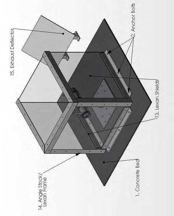
157
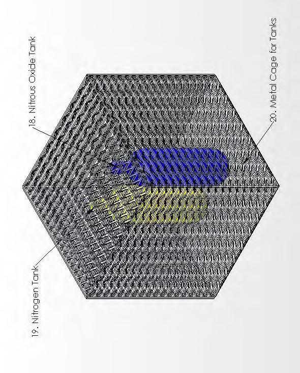
158
159 APPENDIX C Operating, Testing and Maintaining Procedures Setup Procedure Install Test Beam 1. Put base plate in place and tighten down with concrete anchor bolts to a minimum of T req = 6 lb*in 2. Install test beam 3. Install bolts in vertical part of base plate and tighten to a minimum of T req = lb*in 4. Affix engine cradle to top of beam, install and tighten bolts to a minimum of T req = 30 lb*in. Secure Test Chamber 5. Put engine assembly in engine cradle 6. Put 4 straps around rocket and cradle, tighten down to minimum T req = 5.96 lb*in. i. Visually inspect to ensure engine assembly is in contact when flat edge of engine cradle Connect Data Acquisition / Test Electronics 7. Connect thermocouples, pressure sensors and strain gauges to rocket, run wires to DAQ computer 8. Test / Calibrate all gauges 9. Turn on and off inline valves for each tank to ensure successful operation 10. Connect 10 Hose to the Injector on the Rocket Engine Assembly Secure Lexan Panels 11. Put pre-assembled lexan box into place and bolt to the concrete pad 12. Set up thrust deflector approximately 18 from edge of lexan
160 Clear Area 13. Walk perimeter and make sure there is no one in the area that is not with the team 14. Remove any flammable debris that may be around test location 15. Connect 10 hose to cage containing the tanks 16. Connect ignition system to power supply 17. Team members will then be positioned behind barriers to ensure their safety and the test will begin. Setup Checklist Setup # Action Completed Initial Concrete pad inspected for cracks or crumbling 1 Base plate welds inspected for cracks or fatigue 1 All Anchor Bolts installed 1 All Anchor Bolts tightened to at or above required torque 3 All base plate beam bolts installed 3 All base plate beam bolts tightened at or above required torque 3 Test beam pulled with 100 lbs of force and it did not come loose 4 Enging Cradle welds inspected for cracks or fatigue 4 Engine Cradle bolts installed 4 Engine Cradle bolts tightened at or above required torque 4 Test beam with 3 times expected force and it did not come loose Rocket engine body checked for cracks or fatigue 6 4 straps put around the rocket body 6 4 straps tightened around the rocket body 6 Ensure Engine is in contact with flat on Engine Cradle Visually inspect lexan panels for cracks or holes 7 Install sensors 8 Test sensors to make sure they work and are calibrated 9 Test electronic control valves on all tanks 10 Connect interior hose 11 Lexan Box bolted into place 11 Physically make sure panels are secured 12 Set up thrust deflector 18" away from edge of lexan 13/14 Clear perimeter of any bystanders / debris
161 Test Procedure Countdown t = 0 Apply current to igniter, start DAQ t = 0.5 turn on NOx t = 1 Turn off current to igniter 1 < t < test time Pure NOx t = test time Electronically shut off NOx, turn on N 2 t = test time + 3 Electronically shut off N 2, stop DAQ 1. Visually inspect rocket before approaching to ensure flame has extinguished 2. Manually shut off redundant valves on tanks 3. Remove outer hoses 4. Safely remove lexan box and Engine Assembly
162 APPENDIX D Hazards Hazard / Mishap Category Level Control Residual Risks Concrete could crack and break III E Will inspect concrete before use and use an adequate pad. None Anchor bolts may not hold in concrete Not tighten down bolts enough and post releases Welds break at top or bottom Nox tanks explode Straps break or are not tightened III D There will be multiple, redundant, bolts in the concrete, more than one would have to fail for this to be a risk III D This will be checked in our pretest inspection III D Welds will be checked before each test, if welds break the rocket will still be held down by the tethers I D Tanks will be separated from observers by bulletproof material III C This will be checked in our pretest inspection, also there will be properly multiple straps Post breaks III E Post will be inspected before test, if a failure does occur the rocket will still be held down by the tethers Rocket explodes due to excess pressure Exhaust ignites surroundings Injector plate separates from rocket body I E There will be a pressure relief valve on the rocket engine II D There will be an exhaust deflector and we will be cognizant of what is behind the test stand, making sure there is nothing flammable within a reasonable distance II D The straps will hold the tank, the plate on the front of the engine cradle will stop the injector plate None None None Shrapnel None Damage to Lexan or Electronics Shrapnel Small fire None
163 Hazard / Mishap Category Level Control Residual Risks Chunks of fuel are spit out from rocket Nozzle disengages from rocket during firing Valve for any tank is stuck open bolts break in top or bottom clamp Heat causes straps to loosen Hoses burst or become unattached Foreign object enters test stand Shields could break or shatter III C If anything solid is spit out from the nozzle, it will first hit the deflector, breaking it up and then fall harmlessly to the open area behind the rocket II D The nozzle will be moving away from any observer or bystander and will fall harmlessly on the ground IV D No harm in this, except we cannot stop the test, we have to wait for the rocket to burn itself out III E There are multiple bolts in top and bottom, so multiple failures would have to occur if this was to become a problem. However the tethers would still hold the rocket III D Straps self tighten with temperature variation III D If the hoses become unattached the rocket will simply stop, the burst will be contained within the bulletproof panels and shrapnel blanket IV C The test stand will be enclosed on 5 of 6 sides, if an object enters the test stand it could harm the object (if living) but will not be detrimental to the test or any observers I E The shields have been tested with bullets, if they did break they would hopefully slow down any projectile enough that it would fall harmlessly to the ground a few feet from the test cell Debris contacts observer or small fire Debris fly forward and contact observer None None None None None If the shields fail there is nothing between the rocket and pressurized tanks but there is still an additional barrier between observers
164 APPENDIX E Hazardous Materials 1. Nitrous Oxide, N 2 O 2. Nitrogen, N2 3. Hydroxyl Terminated Poly-Butadiene (HTPB tire rubber) 4. Pyrogen / NC Laquer (part of ignition system) 5. Ammonium Perchlorate (part of ignition system) 6. Lexan (Polycarbonate)
165 APPENDIX F Stress Analysis of Critical Components Beam Calculations The Test Beam has been modeled as a solid cantilevered beam, though it has holes in it. This is a valid analysis due to the fact that the parts of the beam that have holes in it are pre-loaded with a force that will ensure the clamp will not spread apart under expected loading conditions. The beam has been sized for a factor of safety of 2. Bolt Analysis To find the required pre-load of the bolts in the bottom of the test beam the geometric center of the bolt pattern was found. From this the maximum expected force in each bolt was determined. This was done in two steps because the bolts will take up the shear force and the couple created by the applied force. To size the bolts the expected force that the bolts will see was set equal to the preload, again to prevent separation of the plates used for clamping. A factor of safety of 2 was used for the calculations. From the pre-load the proof load can be found which leads to the proof strength. Bolts are then selected from Table 8-9 in the Mechanical Engineering Design text book (Shigley, 7 th ed.). The simple calculation for bolt torque is done to find out how much torque should be applied to the bolt during the setup process. Concrete Anchor Bolts The anchor bolts hold the whole test stand to the ground. We must be sure they hold. The concrete will fail long before the actual bolts will fail (~120,000psi for bolts, ~2900psi for concrete), so calculations must be done to determine how much force the concrete can handle. As long as the anchor bolts are embedded at least into the concrete the bolts will have a factor of safety over 40. The torque equation was again used to find out how much torque should be applied to the bolts during the setup process. Strap Analysis Ideally the thrust of the rocket will be perfectly horizontal. Because of the front plate, a moment will be created and the back end of the rocket will tend to move in the upward direction. This is counteracted by the straps that will hold the rocket in the test stand. To plan for the worst case scenario we have done calculations that include only one strap, located at the farthest point from the moment (longest possible moment arm, greatest force) and a thrust that is angled 10 away from horizontal. Even in this worst possible scenario the strap only needs to withstand 39lb. The torque on the bolt was calculated with a factor of safety of 2. The bands themselves have a factor of safety of over 8. Pressurized Cylinder (Combustion Chamber)
166 The tangential stress was found to be the maximum stress experienced by the cylinder. A concentration factor for a pressurized cylinder with one hole in it was used for our calculations. Since there are two holes in our cylinder, we combined them into one larger hole, this is an acceptable assumption. Using Peterson s Stress Concentration Factors a factor of safety of 4 was found for the cylinder, using 304 Stainless Steel. It is also important to note that if the pressure inside our cylinder did for some reason increase to above 1000 psi, that all flow of Oxidizer would halt and this would in turn prevent any possibility of our tank bursting. Injector Plate Bolts These bolts were sized in the exact same manor as the bolts in the previous paragraph Bolt Analysis. Using a factor of safety of 2 the pre-load was set to the expected force, a proof load and proof strength was found from this value and bolts were chosen from Table 8-9 in the Mechanical Engineering Design textbook (Shigley, 7 th ed.). The required torque on the bolts was also calculated. Lexan Analysis Attached at the end of Appendix F is an experiment that was completed by a group of students supervised by Dr. Wellin determining the impact strength of Lexan. As witness from their results the Lexan is able to withstand significant impacts from bullets sized pieces of shrapnel.
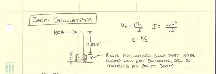
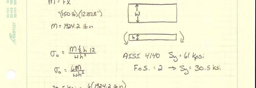


167
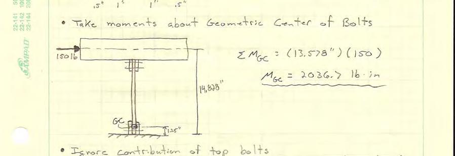
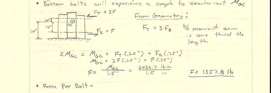
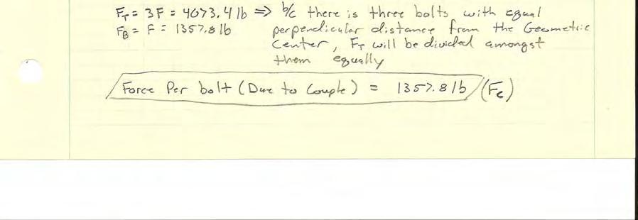
168

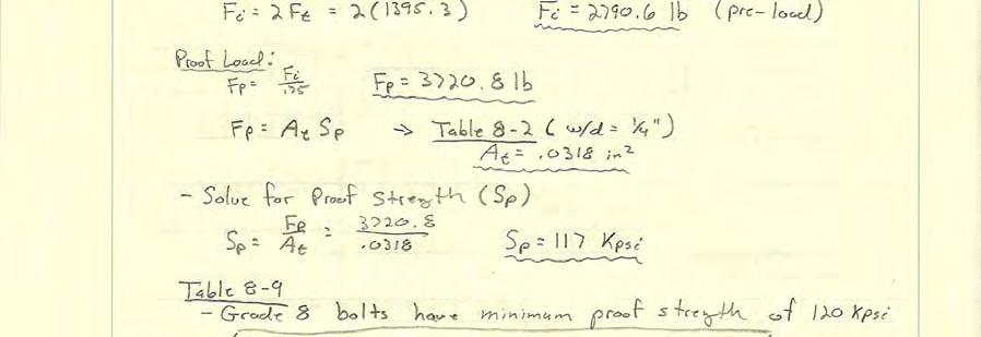

169
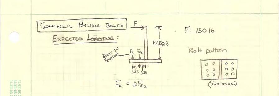
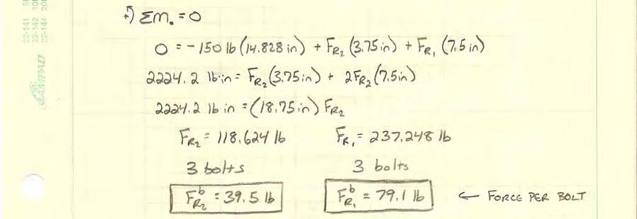

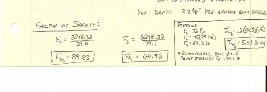
170


171
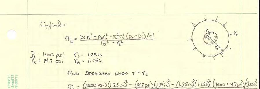

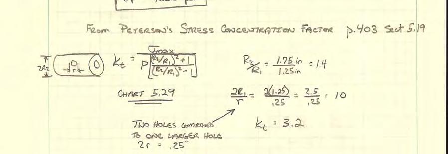
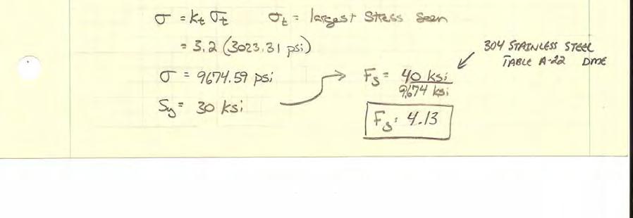
172
173


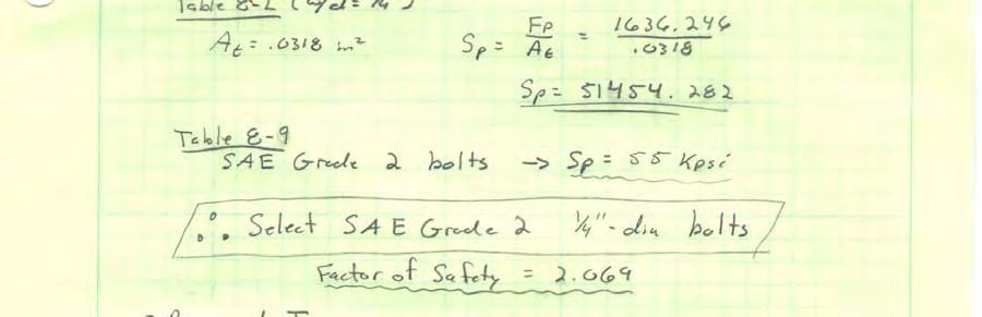

174
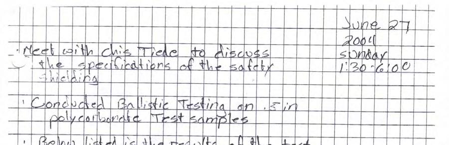
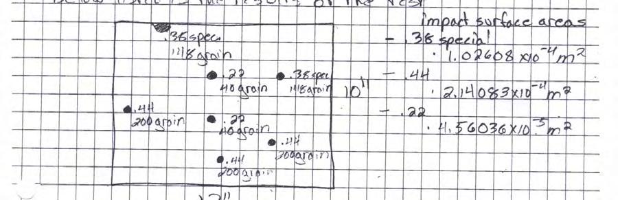
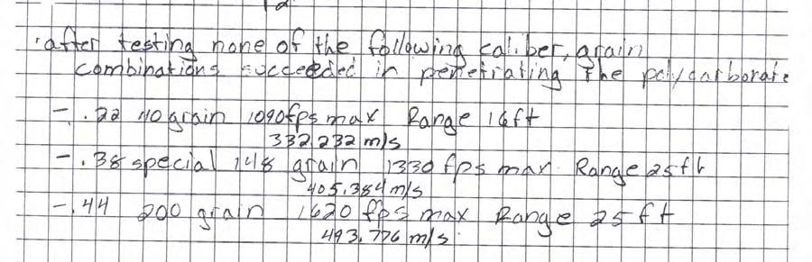

175

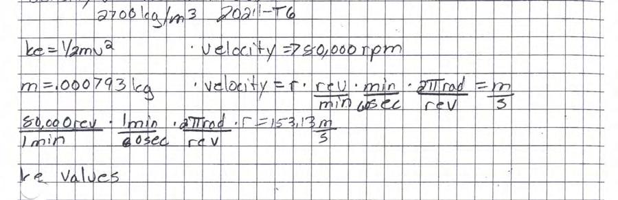
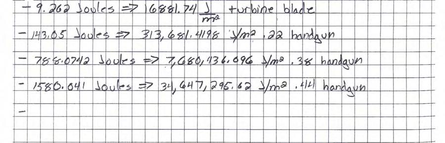
176
Design Review Agenda
 Design Review Agenda 1) Introduction, Motivation, and Previous Work a. Previous Work and Accomplishments i. Platform Launches ii. Successful Test Firings 2) More In-Depth Design Overview of the Existing
The Quarter Pounder A Vehicle to Launch Quarter Pound Payloads to Low Earth Orbit
 The Quarter Pounder A Vehicle to Launch Quarter Pound Payloads to Low Earth Orbit Ed LeBouthillier 1 Contents Introduction... 3 Requirements... 4 Orbital Altitudes... 4 Orbital Velocities... 4 Summary...4
DESIGN AND ANALYSIS OF A COLD GAS PROPULSION SYSTEM FOR STABILIZATION
 DESIGN AND ANALYSIS OF A COLD GAS PROPULSION SYSTEM FOR STABILIZATION AND MANEUVERABILITY OF A HIGH ALTITUDE RESEARCH BALLOON COLLEGE OF ENGINEERING & APPLIED SCIENCES SENIOR DESIGN THESIS GREGORY A. NEFF
Applied Fluid Mechanics
 Applied Fluid Mechanics 1. The Nature of Fluid and the Study of Fluid Mechanics 2. Viscosity of Fluid 3. Pressure Measurement 4. Forces Due to Static Fluid 5. Buoyancy and Stability 6. Flow of Fluid and
WARM GAS PROPULSION FOR SMALL SATELLITES. J. R. French Propulsion Development Associates, Inc. ~1AlN HOUSING CATALY5THOUSP.\G C AT.
 The purpose of this activity is to quickly develop miniature warm gas thruster technology for application to next generation micro satellite systems and to provide an industrial source for this technology.
ZIN Technologies PHi Engineering Support. PHi-RPT CFD Analysis of Large Bubble Mixing. June 26, 2006
 ZIN Technologies PHi Engineering Support PHi-RPT-0002 CFD Analysis of Large Bubble Mixing Proprietary ZIN Technologies, Inc. For nearly five decades, ZIN Technologies has provided integrated products and
LOW PRESSURE EFFUSION OF GASES revised by Igor Bolotin 03/05/12
 LOW PRESSURE EFFUSION OF GASES revised by Igor Bolotin 03/05/ This experiment will introduce you to the kinetic properties of low-pressure gases. You will make observations on the rates with which selected
NANO-LAUNCH REACTION CONTROL SYSTEM 25% Report
 EML 4905 Senior Design Project A B.S. THESIS PREPARED IN PARTIAL FULFILLMENT OF THE REQUIREMENT FOR THE DEGREE OF BACHELOR OF SCIENCE IN MECHANICAL ENGINEERING NANO-LAUNCH REACTION CONTROL SYSTEM 25% Report
College of Engineering
 College of Engineering Department of Mechanical and Aerospace Engineering MAE-250, Section 001 Introduction to Aerospace Engineering Final Project Bottle Rocket Written By: Jesse Hansen Connor Petersen
Launch Vehicle Performance Estimation:
 Launch Vehicle Performance Estimation: John Schilling john.schilling@alumni.usc.edu (661) 718-0955 3 December 2009 Precise determination of launch vehicle performance typically requires the use of three-
LOW PRESSURE EFFUSION OF GASES adapted by Luke Hanley and Mike Trenary
 ADH 1/7/014 LOW PRESSURE EFFUSION OF GASES adapted by Luke Hanley and Mike Trenary This experiment will introduce you to the kinetic properties of low-pressure gases. You will make observations on the
SIMULATION OF ENVIRONMENTAL FLIGHT CONDITIONS
 SIMULATION OF ENVIRONMENTAL FLIGHT CONDITIONS BY ADVANCED ALTITUDE SIMULATION Klaus SCHÄFER Institute of Space Propulsion, German Aerospace Centre (DLR) Lampoldshausen, 74239 Hardthausen, Germany klaus.schaefer@dlr.de
Investigation on Divergent Exit Curvature Effect on Nozzle Pressure Ratio of Supersonic Convergent Divergent Nozzle
 RESEARCH ARTICLE OPEN ACCESS Investigation on Divergent Exit Curvature Effect on Nozzle Pressure Ratio of Supersonic Convergent Divergent Nozzle Shyamshankar.M.B*, Sankar.V** *(Department of Aeronautical
Experimental Verification of Integrated Pressure Suppression Systems in Fusion Reactors at In-Vessel Loss-of -Coolant Events
 Experimental Verification of Integrated Pressure Suppression Systems in Fusion Reactors at In-Vessel Loss-of -Coolant Events K. Takase 1), H. Akimoto 1) 1) Japan Atomic Energy Research Institute (JAERI),
RocketSat V: AirCore. 4/18/09 Symposium Jessica (JB) Brown Mackenzie Miller Emily Logan Steven Ramm. Colorado Space Grant Consortium RocketSat V 1
 Brown Mackenzie Miller Emily Logan Steven Ramm. Colorado Space Grant Consortium RocketSat V 1") : AirCore 4/18/09 Symposium Jessica (JB) Brown Mackenzie Miller Emily Logan Steven Ramm 1 Mission Statement is a team of undergraduate students working in collaboration with NOAA to collect and validate
: AirCore 4/18/09 Symposium Jessica (JB) Brown Mackenzie Miller Emily Logan Steven Ramm 1 Mission Statement is a team of undergraduate students working in collaboration with NOAA to collect and validate
E. MENDOZA, C. KEMPEN, Y. ESTERKIN, S. SUN, K. SUSKO and J. GOGLIA
 6th European Workshop on Structural Health Monitoring - Poster 20 Progress Towards the Development and Qualification of an All Optical Temperature and Pressure Compensated Fiber Optic Oxygen Sensor for
Fig. 2. M.I. Yaroslavtsev, 2002
 SPECIAL FEATURES OF USING N O FOR HEATING OF THE TEST GAS IN A HOT-SHOT WIND TUNNEL M.I. Yaroslavtsev Institute of Theoretical and Applied Mechanics SB RAS, 630090 Novosibirsk Russia 1. The study of heat
Computer Simulation Helps Improve Vertical Column Induced Gas Flotation (IGF) System
 System") JOURNAL ARTICLES BY FLUENT SOFTWARE USERS JA187 Computer Simulation Helps Improve Vertical Column Induced Gas Flotation (IGF) System Computer simulation has helped NATCO engineers make dramatic improvements
JOURNAL ARTICLES BY FLUENT SOFTWARE USERS JA187 Computer Simulation Helps Improve Vertical Column Induced Gas Flotation (IGF) System Computer simulation has helped NATCO engineers make dramatic improvements
Active Control of Vapor Pressurization (VaPak) Systems
 Systems") Active Control of Vapor Pressurization (VaPak) Systems Ralph Ewig, PhD Holder Consulting Group, Renton, WA 98059, USA Vapor pressurized (VaPak) propellant feed systems hold great promise for the development
Active Control of Vapor Pressurization (VaPak) Systems Ralph Ewig, PhD Holder Consulting Group, Renton, WA 98059, USA Vapor pressurized (VaPak) propellant feed systems hold great promise for the development
Offshore platforms survivability to underwater explosions: part I
 Computational Ballistics III 123 Offshore platforms survivability to underwater explosions: part I A. A. Motta 1, E. A. P. Silva 2, N. F. F. Ebecken 2 & T. A. Netto 2 1 Brazilian Navy Research Institute,
DEVELOPMENT OF HIGH ALTITUDE TEST FACILITY FOR COLD JET SIMULATION
 DEVELOPMENT OF HIGH ALTITUDE TEST FACILITY FOR COLD JET SIMULATION Aldin Justin 1, Robin James, Shruti Panicker 2,A.N.Subash,Saravana Kumar 1 Assistant Professor,Karunya University, aldinjustin@karunya.edu
Development of Gasdynamic Probe for Total Temperature Measurement in gases
 ASET 20- National Conference on Emerging Trends in Propulsion Technology Development of Gasdynamic Probe for Total Temperature Measurement in gases K Sathiyamoorthy, Souren Misra 2, Srinivas J, Baskaran
Load Responsive Multilayer Insulation Performance Testing
 Load Responsive Multilayer Insulation Performance Testing S. Dye 1, A. Kopelove 1, and G. L. Mills 2 1 Quest Thermal Group, 6452 Fig Street Suite A, Arvada, CO 80004 USA 2 Ball Aerospace & Technologies
CHAPTER 1 INTRODUCTION
 CHAPTER 1 INTRODUCTION Wind tunnel is a large tube with air moving inside which is used to copy the actions of an object in flight. In wind tunnel air moves around an object, so the object seems like really
CubeSat Balloon Drag Devices: Meeting the 25-Year De-Orbit Requirement
 CubeSat Balloon Drag Devices: Meeting the 25-Year De-Orbit Requirement Jerry K. Fuller, David Hinkley, and Siegfried W. Janson The Aerospace Corporation Physical Science Laboratories August, 2010 The Aerospace
CALCULATING THE SPEED OF SOUND IN NATURAL GAS USING AGA REPORT NO Walnut Lake Rd th Street Houston TX Garner, IA 50438
 CALCULATING THE SPEED OF SOUND IN NATURAL GAS USING AGA REPORT NO. 10 Jerry Paul Smith Joel Clancy JPS Measurement Consultants, Inc Colorado Engineering Experiment Station, Inc (CEESI) 13002 Walnut Lake
MODELLING OF FUME EXTRACTORS C. R.
 LD8 19th International Symposium of Ballistics, 7 11 May 21, Interlaken, Switzerland MODELLING OF FUME EXTRACTORS C. R. Woodley WS4 Guns and Warheads Department, Defence Evaluation and Research Agency,
AC : MEASUREMENT OF HYDROGEN IN HELIUM FLOW
 AC 2010-2145: MEASUREMENT OF HYDROGEN IN HELIUM FLOW Randy Buchanan, University of Southern Mississippi Christopher Winstead, University of Southern Mississippi Anton Netchaev, University of Southern Mississippi
Lab # 03: Visualization of Shock Waves by using Schlieren Technique
 AerE545 Lab # 03: Visualization of Shock Waves by using Schlieren Technique Objectives: 1. To get hands-on experiences about Schlieren technique for flow visualization. 2. To learn how to do the optics
Application Note AN-107
 SPEC Sensor TM Characterization & Calibration Considerations Scope This document is provided to describe the considerations needed to characterize, calibrate, verify and validate the measurement performance
Fluids. James H Dann, Ph.D. Say Thanks to the Authors Click (No sign in required)
") Fluids James H Dann, Ph.D. Say Thanks to the Authors Click http://www.ck12.org/saythanks (No sign in required) To access a customizable version of this book, as well as other interactive content, visit
Fluids James H Dann, Ph.D. Say Thanks to the Authors Click http://www.ck12.org/saythanks (No sign in required) To access a customizable version of this book, as well as other interactive content, visit
Presentation 2 Vehicle Systems - Daedalus
 Presentation 2 Vehicle Systems - Daedalus 1 Outline Structures Nosecone Body tubes Bulkheads Fins Tail Cone Recovery System Layout Testing Propulsion Ox Tank Plumbing Injector Chamber Nozzle Testing Hydrostatic
Conceptual Design and Passive Stability of Tethered Platforms
 Conceptual Design and Passive Stability of Tethered Platforms Sara Smoot Advised by Ilan Kroo 1 Towed Bodies Definition: Two or more tethered objects immersed in a moving fluid. Aerostats Underwater towed
Research and optimization of intake restrictor for Formula SAE car engine
 International Journal of Scientific and Research Publications, Volume 4, Issue 4, April 2014 1 Research and optimization of intake restrictor for Formula SAE car engine Pranav Anil Shinde Mechanical Engineering,
Reliability. Introduction, 163 Quantifying Reliability, 163. Finding the Probability of Functioning When Activated, 163
 ste41912_ch04_123-175 3:16:06 01.29pm Page 163 SUPPLEMENT TO CHAPTER 4 Reliability LEARNING OBJECTIVES SUPPLEMENT OUTLINE After completing this supplement, you should be able to: 1 Define reliability.
AC : ACCURATE CRYOCHAMBER FOR A SMALL LABORATORY WITH SMALL BUDGET
 AC 2007-1108: ACCURATE CRYOCHAMBER FOR A SMALL LABORATORY WITH SMALL BUDGET Matthew Braley, University of Idaho Paul Anderson, University of Idaho Tracey Windley, University of Idaho Kevin Buck, University
WP2 Fire test for toxicity of fire effluents
 Pagina 3 di 89 TRA SFEU VTT 22.6.2009 v.2 WP2 Fire test for toxicity of fire effluents Task 2.1.2 Development of small-scale test method for fire effluents Step 1: Use of modeling Plans according to DoW:
. In an elevator accelerating upward (A) both the elevator accelerating upward (B) the first is equations are valid
 both the elevator accelerating upward (B) the first is equations are valid") IIT JEE Achiever 2014 Ist Year Physics-2: Worksheet-1 Date: 2014-06-26 Hydrostatics 1. A liquid can easily change its shape but a solid cannot because (A) the density of a liquid is smaller than that of
IIT JEE Achiever 2014 Ist Year Physics-2: Worksheet-1 Date: 2014-06-26 Hydrostatics 1. A liquid can easily change its shape but a solid cannot because (A) the density of a liquid is smaller than that of
Lab 1c Isentropic Blow-down Process and Discharge Coefficient
 058:080 Experimental Engineering Lab 1c Isentropic Blow-down Process and Discharge Coefficient OBJECTIVES - To study the transient discharge of a rigid pressurized tank; To determine the discharge coefficients
Investigation of Thermal Effects of CO 2 on Earth-Atmosphere System
 Investigation of Thermal Effects of CO 2 on Earth-Atmosphere System Design Team Michel Beguin, Tim Bevins Dan Jakiela, Frank Kuchinski Design Advisor Prof. Yiannis Levendis Abstract This Capstone Project
High Altitude Deployment Article By Jim Jarvis Rockets Magazine, June 2011 Edited May 2013
 High Altitude Deployment Article By Jim Jarvis Rockets Magazine, June 2011 Edited May 2013 I usually use a CO 2 device for high altitude deployment and it works pretty well. However, in the interest of
The Usage of Propeller Tunnels For Higher Efficiency and Lower Vibration. M. Burak Şamşul
 The Usage of Propeller Tunnels For Higher Efficiency and Lower Vibration M. Burak Şamşul ITU AYOC 2014 - Milper Pervane Teknolojileri Company Profile MILPER is established in 2011 as a Research and Development
Level MEASUREMENT 1/2016
 Level MEASUREMENT 1/2016 AGENDA 2 A. Introduction B. Float method C. Displacer method D. Hydrostatic pressure method E. Capacitance method G. Ultrasonic method H. Radar method I. Laser method J. Level
Paper 2.2. Operation of Ultrasonic Flow Meters at Conditions Different Than Their Calibration
 Paper 2.2 Operation of Ultrasonic Flow Meters at Conditions Different Than Their Calibration Mr William Freund, Daniel Measurement and Control Mr Klaus Zanker, Daniel Measurement and Control Mr Dale Goodson,
Study on Intensity of Blast Wave Generated from Vessel Bursting by Gas Explosion
 5 th ICDERS August 7, 15 Leeds, UK Study on Intensity of Blast Wave Generated from Vessel Bursting by Gas Explosion Matsunaga, T., Mogi, T., Dobashi, R. Graduated School of Engineering, The University
Assessing Compliance with United States Government Orbital Debris Mitigation Guidelines
 Assessing Compliance with United States Government Orbital Debris Mitigation Guidelines R. L. Kelley 1, D. R. Jarkey 2 1. Jacobs, NASA Johnson Space Center, Houston, TX 77058, USA 2. HX5 - Jacobs JETS
Micro Motion 3098 Gas Specific Gravity Meter
 Product Data Sheet PS-001188, Rev. B April 2009 Micro Motion 3098 Gas Specific Gravity Meter Micro Motion density and concentration meters are built to tackle the most demanding process and fiscal applications.
Another convenient term is gauge pressure, which is a pressure measured above barometric pressure.
 VACUUM Theory and Applications Vacuum may be defined as the complete emptiness of a given volume. It is impossible to obtain a perfect vacuum, but it is possible to obtain a level of vacuum, defined as
This test shall be carried out on all vehicles equipped with open type traction batteries.
 5.4. Determination of hydrogen emissions page 1 RESS-6-15 5.4.1. This test shall be carried out on all vehicles equipped with open type traction batteries. 5.4.2. The test shall be conducted following
A. M. Dalavi, Mahesh Jadhav, Yasin Shaikh, Avinash Patil (Department of Mechanical Engineering, Symbiosis Institute of Technology, India)
") IOSR Journal of Mechanical and Civil Engineering (IOSR-JMCE) ISSN(e) : 2278-1684, ISSN(p) : 2320 334X, PP : 45-49 www.iosrjournals.org Modeling, Optimization & Manufacturing of Vortex Tube and Application
IOSR Journal of Mechanical and Civil Engineering (IOSR-JMCE) ISSN(e) : 2278-1684, ISSN(p) : 2320 334X, PP : 45-49 www.iosrjournals.org Modeling, Optimization & Manufacturing of Vortex Tube and Application
1. Air is blown through a pipe AB at a rate of 15 litre per minute. The cross-sectional area of broad
 Keshaw Classes IIT/JEE Medical Classes 5-A 11028 / 9, WEA, Sat Nagar, Karol Bagh New Delhi-110005 Mob:9910915514,9953150192 Ph:011-45660510 E-mail : keshawclasses@gmail.com Web:www.keshawclasses.com Solids
Vortex Meters for Liquids, Gas, and Steam
 A Measuring Principle Comes of Age: Vortex Meters for Liquids, Gas, and Steam Dipl.-Hyd. Oliver Seifert, Product Management Vortex Meters at Flowtec AG, and Ellen-Christine Reiff, M.A., Editor s Office,
Exploration Series. MODEL ROCKET Interactive Physics Simulation Page 01
 MODEL ROCKET ------- Interactive Physics Simulation ------- Page 01 How high will your model rocket fly? At liftoff, the rocket engine is ignited and a thrust force is generated. The rocket accelerates
ROSE-HULMAN INSTITUTE OF TECHNOLOGY Department of Mechanical Engineering. Mini-project 3 Tennis ball launcher
 Mini-project 3 Tennis ball launcher Mini-Project 3 requires you to use MATLAB to model the trajectory of a tennis ball being shot from a tennis ball launcher to a player. The tennis ball trajectory model
Lab Report. Objectives:
 Lab Report Introduction: Aerodynamics is the study of forces and motion of objects that fly/move through the air. Studying aerodynamics allows us to measure the forces of lift and drag. Lift allows an
ANALYSIS OF AERODYNAMIC CHARACTERISTICS OF A SUPERCRITICAL AIRFOIL FOR LOW SPEED AIRCRAFT
 ANALYSIS OF AERODYNAMIC CHARACTERISTICS OF A SUPERCRITICAL AIRFOIL FOR LOW SPEED AIRCRAFT P.Sethunathan 1, M.Niventhran 2, V.Siva 2, R.Sadhan Kumar 2 1 Asst.Professor, Department of Aeronautical Engineering,
Irrigation &Hydraulics Department lb / ft to kg/lit.
 CAIRO UNIVERSITY FLUID MECHANICS Faculty of Engineering nd Year CIVIL ENG. Irrigation &Hydraulics Department 010-011 1. FLUID PROPERTIES 1. Identify the dimensions and units for the following engineering
RATE CONTROL SYSTEM FOR SOUNDING ROCKETS
 RATE CONTROL SYSTEM FOR SOUNDING ROCKETS Josef Ettl, Johann Pfänder German Aerospace Center (DLR), D-834 Wessling, Germany e-mail: josef.ettl@dlr.de johann.pfaender@dlr.de, 1. ABSTRACT DLR/Moraba has a
Series Environmental Chambers
 3119-600 Series Environmental Chambers Challenges in Non-Ambient Testing Testing at non-ambient temperatures adds another layer of challenges to your testing laboratory. Ensuring you get accurate and stable
A Discrete, Multiphase Flow Approach to Monopropellant-Based Micropropulsion
 A Discrete, Multiphase Flow Approach to Monopropellant-Based Micropropulsion M. Ryan McDevitt Advisor: Darren Hitt, Ph.D. Mechanical Engineering Program School of Engineering The University of Vermont
Flow in a shock tube
 Flow in a shock tube April 30, 05 Summary In the lab the shock Mach number as well as the Mach number downstream the moving shock are determined for different pressure ratios between the high and low pressure
ISSN: Page 410
 Study of Structural Stability of Globe Valve in Petroleum and Sugar Industries Anil Rathod 1, Dr. S N Kurbet 2 1 PG Student Mechanical branch (machine Design) BEC Bagalkot, Karnataka India, 2 HOD of Mechanical
Drilling Efficiency Utilizing Coriolis Flow Technology
 Session 12: Drilling Efficiency Utilizing Coriolis Flow Technology Clement Cabanayan Emerson Process Management Abstract Continuous, accurate and reliable measurement of drilling fluid volumes and densities
Numerical and Experimental Investigation of the Possibility of Forming the Wake Flow of Large Ships by Using the Vortex Generators
 Second International Symposium on Marine Propulsors smp 11, Hamburg, Germany, June 2011 Numerical and Experimental Investigation of the Possibility of Forming the Wake Flow of Large Ships by Using the
AIRFLOW GENERATION IN A TUNNEL USING A SACCARDO VENTILATION SYSTEM AGAINST THE BUOYANCY EFFECT PRODUCED BY A FIRE
 - 247 - AIRFLOW GENERATION IN A TUNNEL USING A SACCARDO VENTILATION SYSTEM AGAINST THE BUOYANCY EFFECT PRODUCED BY A FIRE J D Castro a, C W Pope a and R D Matthews b a Mott MacDonald Ltd, St Anne House,
Design of a Solid Wall Transonic Wind Tunnel
 Design of a Solid Wall Transonic Wind Tunnel David Wall * Auburn University, Auburn, Alabama, 36849 A solid wall transonic wind tunnel was designed with optical access from three sides to allow for flow
44 (0) E:
 E:") FluidFlow Relief Valve Sizing Handbook Flite Software 2016 Flite Software N.I. Ltd, Block E, Balliniska Business Park, Springtown Rd, Derry, BT48 0LY, N. Ireland. T: 44 (0) 2871 279227 E: sales@fluidflowinfo.com
FluidFlow Relief Valve Sizing Handbook Flite Software 2016 Flite Software N.I. Ltd, Block E, Balliniska Business Park, Springtown Rd, Derry, BT48 0LY, N. Ireland. T: 44 (0) 2871 279227 E: sales@fluidflowinfo.com
Project Background and Scope
 Project Background and Scope The purpose of the project is to generate a design that can easily and effectively convert a Laser sailboat to a human powered Flettner ship. A Flettner ship is a ship that
Loads, Structures, and Mechanisms. Team C5 Matthew Marcus Chris O'Hare Alex Slafkosky Scott Wingate
 Loads, Structures, and Mechanisms Matthew Marcus Chris O'Hare Alex Slafkosky Scott Wingate Presentation Overview Design requirements Initial crew capsule design choice Pressure vessel design Pressure loads
Project to Refine a Prototype Unmanned, Tethered ADCP Platform for Measuring Streamflow
 Pagina 1 di 5 Project to Refine a Prototype Unmanned, Tethered ADCP Platform for Measuring Streamflow The use of trade, firm, or product names is for descriptive purposes only and does not imply endorsement
5.0 Neutral Buoyancy Test
 5.0 Neutral Buoyancy Test Montgolfier balloons use solar energy to heat the air inside the balloon. The balloon used for this project is made out of a lightweight, black material that absorbs the solar
DEVELOPMENT OF P4.1 ALTITUDE SIMULATION FOR VINCI ENGINE
 DEVELOPMENT OF P4.1 ALTITUDE SIMULATION FOR VINCI ENGINE K. Schäfer, C. Böhm, H. Kronmüller, H. Zimmermann, German Aerospace Centre (DLR), Institute of Space Propulsion, Lampoldshausen, 74172 Hardthausen,
Gases and Pressure SECTION 11.1
 SECTION 11.1 Gases and In the chapter States of Matter, you read about the kineticmolecular theory of matter. You were also introduced to how this theory explains some of the properties of ideal gases.
Gases and Pressure. Main Ideas
 Gases and Pressure Key Terms pressure millimeters of mercury partial pressure newton atmosphere of pressure Dalton s law of partial pressures barometer pascal In the chapter States of Matter, you read
At the end of this lesson, you will be able to do the following:
 Liquid-Phase Contacting Scrubbers Goal To familiarize you with the operation, collection efficiency, and major maintenance problems of liquid-phase contacting scrubbers. Objectives At the end of this lesson,
GUIDE TO RUNNING A BIKE SHARE. h o w t o p l a n a n d o p e r a t e a s u c c e s s f u l b i k e s h a r e p r o g r a m
 GUIDE TO RUNNING A BIKE SHARE h o w t o p l a n a n d o p e r a t e a s u c c e s s f u l b i k e s h a r e p r o g r a m 20150209 The bicycle is the most loved form of transportation. No other machine
DEVELOPMENT AND TESTING OF AIR EXCHANGE RATE METHODS TO IMPROVE COST EFFECTIVENESS WHILE MAINTAINING ACCURACY
 DEVELOPMENT AND TESTING OF AIR EXCHANGE RATE METHODS TO IMPROVE COST EFFECTIVENESS WHILE MAINTAINING ACCURACY Prepared by: Joachim Eberharter (Joachim.Eberharter@tetratech.com) and James Elliot (Tetra
CFD Simulation and Experimental Validation of a Diaphragm Pressure Wave Generator
 CFD Simulation and Experimental Validation of a Diaphragm Pressure Wave Generator T. Huang 1, A. Caughley 2, R. Young 2 and V. Chamritski 1 1 HTS-110 Ltd Lower Hutt, New Zealand 2 Industrial Research Ltd
CONSIDERATION OF DENSITY VARIATIONS IN THE DESIGN OF A VENTILATION SYSTEM FOR ROAD TUNNELS
 - 56 - CONSIDERATION OF DENSITY VARIATIONS IN THE DESIGN OF A VENTILATION SYSTEM FOR ROAD TUNNELS Gloth O., Rudolf A. ILF Consulting Engineers Zürich, Switzerland ABSTRACT This article investigates the
ENSURING AN ACCURATE RESULT IN AN ANALYTICAL INSTRUMENTATION SYSTEM PART 1: UNDERSTANDING AND MEASURING TIME DELAY
 ENSURING AN ACCURATE RESULT IN AN ANALYTICAL INSTRUMENTATION SYSTEM PART 1: UNDERSTANDING AND MEASURING TIME DELAY Process measurements are instantaneous, but analyzer responses never are. From the tap
Vibration-Free Joule-Thomson Cryocoolers for Distributed Microcooling
 Vibration-Free Joule-Thomson Cryocoolers for Distributed Microcooling W. Chen, M. Zagarola Creare Inc. Hanover, NH, USA ABSTRACT This paper reports on an innovative concept for a space-borne Joule-Thomson
Blast Damage Consideratons for Horizontal Pressure Vessel and Potential for Domino Effects
 A publication of CHEMICAL ENGINEERING TRANSACTIONS VOL. 26, 2012 Guest Editors: Valerio Cozzani, Eddy De Rademaeker Copyright 2012, AIDIC Servizi S.r.l., ISBN 978-88-95608-17-4; ISSN 1974-9791 The Italian
From and
 From http://www.school-for-champions.com/science/fluidpressure.htm and http://www.school-forchampions.com/science/fluidfloating.htm by Ron Kurtus, School for Champions Pressure in Fluids by Ron Kurtus
VACUUM TESTING PRECAST CONCRETE MANHOLES
 1 OF 5 testing is a quick, safe and practical way to validate manhole system integrity. Manhole sections can be tested at the precast concrete plant prior to delivery or on site prior to backfilling. Here
acrolein, acetaldehyde and acetone( cm -1 ); methanol (1306 cm -1 ); ethylene (949 cm -1 ); and isoprene (893 cm -1 ).
; methanol (1306 cm -1 ); ethylene (949 cm -1 ); and isoprene (893 cm -1 ).") acrolein, acetaldehyde and acetone(1550 1800 cm -1 ); methanol (1306 cm -1 ); ethylene (949 cm -1 ); and isoprene (893 cm -1 ). 5 Figure 4a 6 Figure 4b Figure 4c 7 Figure 5 Questions in Student Handout
acrolein, acetaldehyde and acetone(1550 1800 cm -1 ); methanol (1306 cm -1 ); ethylene (949 cm -1 ); and isoprene (893 cm -1 ). 5 Figure 4a 6 Figure 4b Figure 4c 7 Figure 5 Questions in Student Handout
Space Launchers. Cryogenic, gas-related equipment and engineering solutions for launchers and launch pads infrastructures
 Space Launchers Cryogenic, gas-related equipment and engineering solutions for launchers and launch pads infrastructures Launcher equipment Cryogenic propulsion enables a significant increase of space
Up Up and Away on Beautiful Balloons: Scaling up from Party Favors to Scientific Payloads
 Up Up and Away on Beautiful Balloons: Scaling up from Party Favors to Scientific Payloads How many helium filled balloons would it take to lift you? To lift a big telescope? Take a guess for each and record
Mass Split of Two-Phase-Flow
 Mass Split of Two-Phase-Flow The split of two-phase-flow at horizontal side-t-junctions in unbalanced pipe systems for clean extinguishing agents Speaker: Gudrun Fay Minimax 2010 2013 Content 1. Applications
Numerical Simulations of a Train of Air Bubbles Rising Through Stagnant Water
 Numerical Simulations of a Train of Air Bubbles Rising Through Stagnant Water Hong Xu, Chokri Guetari ANSYS INC. Abstract Transient numerical simulations of the rise of a train of gas bubbles in a liquid
Becker* Products Below Ground Ball Valve Regulators
 GE Oil & Gas Becker* Products Below Ground Ball Valve Regulators Reduce Noise Levels at Large Volume Regulator Stations GE s Becker* Below Ground ball valve regulator has the long-term proven reliability,
UNITED KINGDOM ROCKETRY ASSOCIATION STUDY GUIDE SAFETY OFFICERS EXAMINATION AND LEVEL II FLIGHT CERTIFICATION EXAMINATION
 UNITED KINGDOM ROCKETRY ASSOCIATION STUDY GUIDE SAFETY OFFICERS EXAMINATION AND LEVEL II FLIGHT CERTIFICATION EXAMINATION Page 1 of 15 This document is published by the Council of the United Kingdom Rocketry
Modeling Case Study: Surge Tanks, Valves, Level sensors, and modeling
 Modeling Case Study: Surge Tanks, Valves, Level sensors, and modeling By Peter Woolf (pwoolf@umich.edu) University of Michigan Michigan Chemical Process Dynamics and Controls Open Textbook version 1.0
1 PIPESYS Application
 PIPESYS Application 1-1 1 PIPESYS Application 1.1 Gas Condensate Gathering System In this PIPESYS Application, the performance of a small gascondensate gathering system is modelled. Figure 1.1 shows the
Dual-Thrust Rocket Motor with an intermediate Nozzle at the condition of higher boosting pressure than the sustaining pressure
 16 th International Conference on AEROSPACE SCIENCES & AVIATION TECHNOLOGY, ASAT - 16 May 26-28, 2015, E-Mail: asat@mtc.edu.eg Military Technical College, Kobry Elkobbah, Cairo, Egypt Tel : +(202) 24025292
SEMATECH Provisional Test Method for Pressure Cycle Testing Filter Cartridges Used in UPW Distribution Systems
 Provisional Test Method for Pressure Cycle Testing Filter Cartridges Used in UPW Distribution Systems Technology Transfer 92010941B-STD and the logo are registered service marks of, Inc. 1996, Inc. Provisional
Exercise 5-2. Bubblers EXERCISE OBJECTIVE DISCUSSION OUTLINE. Bubblers DISCUSSION. Learn to measure the level in a vessel using a bubbler.
 Exercise 5-2 Bubblers EXERCISE OBJECTIVE Learn to measure the level in a vessel using a bubbler. DISCUSSION OUTLINE The Discussion of this exercise covers the following points: Bubblers How to measure
Detector Carrier Gas Comments Detector anode purge or reference gas. Electron Capture Nitrogen Maximum sensitivity Nitrogen Argon/Methane
 Gas requirements Gases for packed columns The carrier gas you use depends upon the type of detector and the performance requirements. Table 520-1 lists gas recommendations for packed column use. In general,
Low Speed Wind Tunnel Wing Performance
 Low Speed Wind Tunnel Wing Performance ARO 101L Introduction to Aeronautics Section 01 Group 13 20 November 2015 Aerospace Engineering Department California Polytechnic University, Pomona Team Leader:
Laboratory Hardware. Custom Gas Chromatography Solutions WASSON - ECE INSTRUMENTATION. Engineered Solutions, Guaranteed Results.
 Laboratory Hardware Custom Gas Chromatography Solutions Engineered Solutions, Guaranteed Results. WASSON - ECE INSTRUMENTATION Laboratory Hardware Wasson-ECE Instrumentation offers hardware-only solutions
Test Flights of the Revised ULDB Design
 Test Flights of the Revised ULDB Design Michael S. Smith * Aerostar International, Inc., Sulphur Springs, TX 75482, USA Henry M. Cathey, Jr. Physical Science Laboratory, New Mexico State University, Wallops