OPERATING MANUAL. Model 900
|
|
|
- Ira Bell
- 5 years ago
- Views:
Transcription


1 OPERATING MANUAL Model 900 NON-VIABLE PARTICLE SIZING INSTRUMENTS Eight Stage Models BGI20800 Series BGI Incorporated 58 Guinan Street Waltham, MA USA Tel : Fax: info@bgiusa.com Version November, 2009
2 Table of Contents 1. Preface Introduction 1 3. Aerodynamic Particle Sizing Cascade Non-Viable Impactor 4 A. Description 4 B. Preparation for Use 7 C. Sampling 8 D.Analysis. 9 E. Data Interpretation. 9 F. Calibration. 14 G. 60 Liter Per Minute Conversion Kit. 16 H. 90 Liter Per Minute Conversion Kit. 18 I. Cleaning Method for 8 Stage Non-Viable Impactors 20 TABLE OF FIGURES AND TABLES Figure 1 BGI Sampler Simulates Human Respiratory System 2 Figure 2 BGI Cascade Impactor with USP Pre-Separator & Throat..4 Figure 3 Schematic Cross Section 5 Figure 4 Jet Dimensions 6 Figure 5 Schematic of Impactor Stage..8 Table 1 Data Presentation 11 Figure 6 Fractional Efficiency Curves..12 Figure 7 Particle Size Diameter Graph.13 Figure 8 Exploded View of 8-Stage Impactor..15
3 1. PREFACE For thirty years, industrial hygienists have been aware of the potential health effects associated with exposure to fine particles, and within the past ten years, inertial impactors have been used universally for monitoring particulate sizes in the work place. Knowledge of the aerodynamic dimension of the particles is vital to understanding their effects and to determining the best methods of control. The purpose of this manual is to outline proper methods for the simultaneous determination of concentration and particle sizing information in the working environment using the BGI Instruments (BGI) Non-Viable Ambient Particle Sizing Samplers. This technique is based on Cascade Impaction. 2. INTRODUCTION The BGI Non-Viable Particle Sizing Sampler is a multi-stage, multi- orifice cascade impactor, which normally is used in the environmental working areas to measure the size distribution and total concentration levels of all liquid and solid particulate matter. The BGI Non-Viable Ambient Sampler was calibrated with unit density (1 g/cm 3 ) spherical particles so that all particles collected, regardless of their physical size, shape, or density, are sized aerodynamically equivalent to the reference particles. In this manner, the aerodynamic dimensions obtained in the work place can be used to determine the following: 1) Probable point of respiratory deposition 2) Particle behavior in the air 3) Type of control equipment needed to collect the particles 4) Compliance with existing Threshold Limit Values and OSHA Regulations A brief description of the operation of the equipment follows: 1) Ambient gases enter the impactor inlet cone and cascade through the succeeding orifice stages with successively higher orifice velocities from Stage 0 to Stage 7. Successively smaller particles are inertially impacted onto the collection plates. The submicrometer particles, which are not collected by the last collection plate, are caught in the backup filter, which is an integral part of the impactor immediately downstream from Stage 7. Stage 0 is an orifice stage only. Stage 8 is a collection stage only. 2) The clean gases are carried through the vacuum tube and through the air pump and exhausted. 3) A constant air sample flow of 1 ACFM (28.3LPM) is provided by a continuous duty, carbonvane vacuum pump. Flow rate through the impactor is controlled by an adjustable bleed valve on the pump, which requires periodic flow calibration to site conditions. 4) After sampling is completed, the sample time is recorded and the tared weighed 81mm collection media and backup filter are removed for subsequent gravimetric and/or chemical determination. 5) Concentration levels are determined and the size distribution is plotted. At this point an assessment of the working environment can be made. 1

4 3. AERODYNAMIC PARTICLE SIZING The design concept of the BGI Non-Viable Ambient Particle Sizing Sampler evolved from the following facts: The human respiratory tract is an aerodynamic classifying system for airborne particles. 2,4 The sampling device is used as a substitute for the respiratory tract as a dust collector. As such, it should reproduce to a reasonable degree the dust collecting characteristics of the human respiratory system 1,4 so that lung penetration by airborne particles can be predicted from sampling data. The sampling instrument should therefore classify the particles collected according to the aerodynamic dimension which, as Wells 5 states, is the true measure of lung penetrability. The fraction of inhaled dust retained in the respiratory system and the site of deposition vary with size, shape, and density and all the physical properties of the particles that constitute the aerodynamic dimensions (Figure 1). Figure 1: BGI Style Sampler Simulates Human Respiratory System 2
5 Methods that employ light scattering or filtration and microscopic sizing of particles do not reckon with density and some other properties that affect the movement of the particle in air, and therefore do not give the desired information. Because the lung penetrability of unit density spherical particles is known and since the particle sizes that are collected on each stage of the sampler have been determined, then, as long as a standard model of this sampler is used according to standard operating procedure, the stage distribution of the collected material will indicate the extent to which the sampler would have penetrated the respiratory system. With this information and with knowledge of the chemical, biological, and/or radiological properties of the material collected, the exact nature and extent of the health hazard can be assessed 15. The earliest and most fundamental work in inertial impaction theory was conducted in the early 1950's by Ranz & Wong. In this work, Ranz and Wong showed that the collection of a particle by an obstacle is a function of what is defined as the inertial impaction parameter (K): K = CpUDp 2 18µD c Where U is the relative velocity, p is the particle density, D p is the particle diameter, µ is the gas viscosity, D c is the diameter of the round jet, and C is the Cunnigham slip correction factor. Data from inertial impactors are normally presented as 50% effective cut-off diameter. For the BGI Environmental Impactors, containing round jets and flat collection surfaces, the 50% effective cut-off diameter would yield a value of 0.14 for the inertial impaction parameter K. The Cunningham slip correction factor (C) is equal to: C = 1 + (0.16 x 10⁻⁴/D p ) for normal temperatures and pressures. This factor corrects for the fact that as particle diameters approach the mean free- path length of the gas molecules, they tend to "slip" between gas molecules more easily and are therefore more easily able to cross the bulk flow streamlines. The collection efficiency is therefore slightly greater than would be predicted by inertial impaction theory for particle diameters on the order of 1 or 2 micrometers. The overlapping of particle size between stages, which is naturally inherent in all cascade impaction devices, is minimized in BGI Impactors by design. Ranz and Wong (1952) stated that as a particle passes through a jet, its nearness to the axis of the jet is one of the factors that determine whether or not the particle will reach the impaction surface. In contrast to competitive samplers which have larger rectangular jets in each stage, the BGI Impactor has 400 small, round jets. Travel of the particle is thus confined near the axis of the jets. The average distance of the particles from the axis of the jets is much less than in other Impactors. Ranz and Wong (1952) also stated that round jets have sharper cut-offs than rectangular jets. The BGI Impactor, therefore, on a theoretical basis, should have a sharper cutoff8. 3
. 4.")
6 An inherent disadvantage of competitive samplers is that single circular orifice and multiple rectangular orifice Impactors by design must operate with high orifice velocities. This results in more turbulent flow, greater re-entrainment, and a skewing of the size distribution toward the lower end (i.e., the indicated size distribution being smaller than it really is). 4. CASCADE NON-VIABLE IMPACTOR A. DESCRIPTION The BGI 1ACFM (28.3 LPM) Ambient Sampler is comprised of eight aluminum stages that are held together by three spring clamps and sealed with silicone O-ring seals (Figure 2). Figure 2: BGI Cascade Impactor with USP Pre-separator and Throat Each impactor stage contains multiple precision drilled orifices. When air is drawn through the sampler, multiple jets of air in each stage direct any airborne particles toward the surface of the collection plate for that stage. The size of the jets is constant for each stage, but is smaller in each succeeding stage. Whether a particle is impacted on any given stage depends on its aerodynamic dimension. The range of particle sizes collected on each stage depends on the jet velocity of the stage and the cut-off of the previous stage. Any particle not collected on the first stage follows the air stream around the edge of the plate to the next stage, where it is either impacted or passed on to the succeeding stage, and so on until the jet velocity is sufficient for impaction. There are two separate types of Ambient Samplers in use. The original design in which all eight stages contained orifices arranged in a circular pattern (Mark I) and the updated design in which the top two orifice stages contained orifices arranged in a radial pattern and the other six stages contained orifices arranged in a circular pattern (BGI-Style). All samplers purchased prior to September 1977 were Mark I and all samplers purchased after 1977 are current. 4
 design has fewer holes with larger diameters on the top two stages and the orifice holes are tapered and arranged in a radial pattern to reduce turbulence.")
7 The design change from Mark I to BGI-Style was made as a result of research work showing the wallloss and particle-bouncing errors inherent in the original design. The BGI-Style (Mark II) design has fewer holes with larger diameters on the top two stages and the orifice holes are tapered and arranged in a radial pattern to reduce turbulence. The following is a description of the Mark I and BGI Mark II Style samplers: Mark I: Stages 0-6 have integral air inlet sections that contain 400 orifices arranged in a circular pattern. Stage 7 contains 201 orifices arranged in a circular pattern. The inlet sections are approximately 3.125" in diameter. The orifices are progressively smaller from top to bottom stages, ranging from " diameter in Stage 0 to " diameter in Stage 7. Each stage has a removable stainless steel or glass (3.25" diameter) collection plate. The exhaust section of each stage is approximately 0.75" larger in diameter than the collection plate, allowing unimpacted particles to go around the plate and into the next stage (Figure 3). Figure 3: Schematic cross section of the non-viable impactor stages. Progressively smaller orifices increase the orifice velocity in eight successive stages causing impaction of smaller particles onto the collection discs of each succeeding stage. BGI-Style (Model Mark II): Orifice Stages 0 and 1 have integral air inlet sections that contain 96 orifices arranged in a radial pattern. Stages 2 through 6 have integral air inlet sections that contain 400 orifices arranged in a circular pattern. Stage 7 contains 201 orifices arranged in a circular pattern. The orifices are progressively smaller from top to bottom stages, ranging from " diameter on stage 0 to diameter on stage 7. Each stage has a removable stainless steel collection plate. The exhaust section of each stage is approximately 0.75" larger in diameter than the collection plate, allowing unimpacted particles to go around the plate and into the next stage (Figure 3). The top two stainless steel collection plates have 7/8" holes in the center to allow air flow through the center also. 5
8 Impactor Pre-separator If sampling in environments containing particles larger than 10 micrometers, a pre- separator must be used to prevent particle bouncing and re-entrainment errors. Researchers have shown that significant errors will occur with large particles if no pre-separator is used. The BGI Non-Viable Impactor preseparator is an impaction chamber with one 0.53" diameter inlet orifice and three outlet vent tubes. The outlet tubes are 1.0" above the impaction surface. This design results in very low turbulence and allows collection of several grams of particulate without overloading the pre-separator. The device acts as a plenum to remove large >10micron particles. When using the pre-separator, simply replace the standard inlet cone on the sampler with the preseparator. The pre-separator base contains three spring hold-down slots, and fits the BGI Impactor with no further adjustment required. The BGI Non-Viable Ambient Sampler and vacuum pump include their own carrying case for ease of portability. A constant air sample flow of 1 ACFM (28.3LPM) is provided by a continuous duty vacuum pump. Flow rate is controlled by an adjustable valve on the pump and periodic calibration is recommended. Requirements for flow rate adjustments can be found in Section F. The sampler is supplied with a builtin backup filter which will accommodate an 81 mm filter disc. Normally, binder less glass fiber 81mm filter media is used because of its high collection efficiency for sub micrometer particles. Following are the jet dimensions for each stage (Figure 4): BGI Mark II Mark I Stage Orifice Diameter Orifice Diameter Number of Orifi (inches) (inches) Number of Orifi F.110 Filter Holder Filter Holder Figure 4: Jet Dimensions for Each Stage 6
9 B. PREPARATION FOR USE The orifice stages, pre-separator and collection plates must be clean before assembly of the Sampler. A mild detergent and warm water are sufficient for cleaning. The soap can be removed by holding the stages and plates under hot running water. Complete soap removal for the stages is more quickly done by immersing them in an ultrasonic cleaner containing clean water. After the soap is removed, the stages and plates may be rinsed with acetone which removes the water and which itself quickly evaporates, or they can be spread out on paper towels and blotted dry. Either operation may leave slight traces of film which are easily removed with a lint-free wiping paper. The stages and plates should be handled by the edge to prevent getting skin oil on the orifice and collection surfaces. Each stage should be examined for any material in the holes. If holes are plugged, or partially plugged, a jet blast of dry air, or a portable Freon gun, is effective in cleaning the holes. The complete impactor assembly consists of an inlet cone, nine stages, eight collection plates and a backup filter. An impactor pre-separator is optional. The stages are numbered 0, 1, 2, 3, 4, 5, 6, 7 and F. Stage 0 is an orifice stage only. Stage F contains the collection plate for Stage 7 and the backup filter. Each stage contains an O-ring (Silicone Standard, Teflon optional) for sealing. In addition, there is a large-diameter O-ring inside Stage F which holds the backup filter in place. The optional pre-separator simply replaces the inlet cone and requires no modification. The impactor assembly begins by placing Stage F on the base plate stage. A pre- weighed 81mm glass fiber backup filter is inserted into Stage F and the large-diameter O- ring placed into position around the periphery of the filter. Next, place pre-weighed collection plate No. 7 onto Stage F so that the plate rests on the three raised, notched metal seats to prevent plate movement. There is no differentiation between top and bottom for the glass plates. The stainless steel plates should be placed with the curved lip down so that a raised, smooth surface is exposed for particle impingement. This is followed by Stage 7, collection plate 6, Stage 6, and so on until the inlet cone or pre-separator is positioned last. Note that if you have a BGI Style sampler, the stainless steel collection plates that fit onto the raised notched seats on top of stages 2 and 1 should have a 7/8" hole in the center of the plates. It should be noted that there are three metal pins extending from the base of each orifice stage. These pins hold the collection plates in place so that the sampler can be used in any sampling orientation. In addition, most people use special collection substrates other than the glass and stainless steel plates because of lighter tare weight and/or specific analytical requirements. These collection materials consist of glass fiber, cellulose, aluminum foil, vinyl metrical and other materials which must be placed into the inverted stainless steel collection plate. The collection substrate for plates 1 and 2 have open centers (7/8" hole) while the remaining 6 collection discs and backup filter are solid. The substrate surface must be level with the top of the curved stainless steel lip to maintain jet-tocollection-surface spacing. When using collection substrates, the Sampler should be used in an upright position at all times. After the Sampler has been assembled, connect the outlet nipple on the base stage to the pump intake port with the rubber tubing supplied with the sampler. If a longer piece of tubing is required in order to position the Sampler remotely from the vacuum source, refer to Section F for re-calibration procedures. 7
10 C. SAMPLING When ready to sample, the vacuum pump is turned on and a sample stream of 1 ACFM will flow through the sampler. Figure 5 shows how impaction occurs at the orifice collector interfaces. Normally, there is no variation in flow rate throughout the sampling period since a constant pressure drop is maintained (no filtration occurs except at the backup filter, resulting in minimal pressure changes). The particle size range collected at each of the eight stages depends on the orifice velocity of the specific stage, the distance between the orifices and the collection surface, and the collection characteristics of the proceeding stage. The combination of a constant flow rate and successively smaller diameter orifices increases the velocity of sample air as it cascades through the Sampler, resulting in the impaction of progressively smaller particles in succeeding stages. At 1 ACFM (28.3LPM) the particle fractionation ranges from 10.0 to 0.4 micrometers diameter (Figure 1). Particles too small to be impacted on the last collection plate are collected in the backup filter which is an optional, integral part of the sampler. Normal sampling periods vary from a few minutes to several hours, depending upon the workroom contamination levels and the sensitivity of the analytical procedure. Ten milligrams of particulate matter on any one stage represents an approximate upper limit because of re-entrainment problems. Overloading the Sampler can be detected easily by visual inspection and is rarely encountered in industrial hygiene applications. Whenever over-sampling occurs, rather than having well-defined, discrete piles of particulates, trails of particles can be seen leading from the sample deposits toward the periphery of the plate. This type of sample should be discarded. Figure 5: Schematic of Impactor Dtage 8
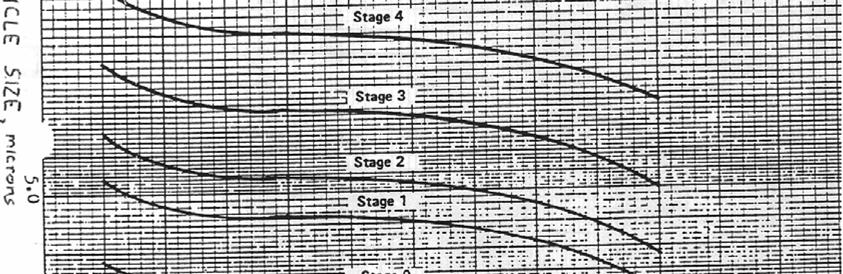
11 After the sampling has been completed, the Sampler is disassembled. The collection plates and backup filter are removed and replaced with fresh, preconditioned, preweighed collection media. After conditioning, the collection media can be weighed for net particulate accumulations, or the particulate matter can be analyzed chemically for the various components of interest. Since airborne particulates have hygroscopic characteristics, all collection media used in the impactor should be preconditioned prior to weighing both before and after a sampling cycle in a desiccator. Filter weighing should be made to an accuracy of ± 0.02 mg and a precision of ± 0.01 mg. It should be kept in mind that whenever a sample has been collected, the particle sizing has already been completed. To determine the nature of the size distribution, simply perform the required gravimetric and/or chemical analyses. D. ANALYSIS The analytical requirements determine the type of collection surface used. Normally, the stainless steel and glass plates are not used as the collection surfaces for gravimetric determinations because of the high tare-weight-to-sample-weight ratio. Glass fiber discs are normally used for these analyses because of their light weight and non-hygroscopic properties. However, other types of collection media are required for most chemical determinations because of the high and variable trace metal background levels in glass fiber. Stainless steel plates are used in many applications where the collected sample is washed off for subsequent chemical analyses. Glass plates are used rarely and only when there is need to look at the collected particles optically. It is impossible to correlate aerodynamic dimensions with physical size because of the unknown particle density and shape characteristics. In addition, the particles might have shattered in impaction, which will not affect the aerodynamic sizing but would affect any optical sizing significantly. E. DATA INTERPRETATION a) Determine the change in weight for each stage in the impactor including the backup filter. b) Add up the weight changes to obtain the total particulate weight collected. c) Divide the amount collected on each stage by the total amount collected to determine the percentage of the total collected in each fraction (Table 1).* *Note that the preseparator fraction is added to Stage 0 and the sum of both fractions is larger than the D p50 for Stage 0. In summary, the pre-separator does not give an additional size cut, but prevents particle bouncing and re-entrainment so that the impactor stages perform properly. d) The particle density should be considered as 1.0 g/cm 3 so that the particle sizes can be reported as equivalent aerodynamic diameters. e) Using Figure 1, select the lower size (smallest number) for each size range. This number represents the effective cut-off diameter (ECD) for each stage. This ECD can also be obtained from Figure 6. 9
12 f) Graph the results on log-probability paper with the ECD as the ordinate and the cumulative percent less than the size range by weight as the abscissa (Figure 7). g) Assuming a log-normal particle size distribution, the particle size geometric standard deviation σ g is given by: σ g = 84.13% Diameter = 50% Diameter 50% Diameter 15.87% Diameter Whenever these two standard deviations are not equal (such as represented in a bimodal distribution), then the size distribution is not represented by a straight line (not really log-normal). A better method of presenting the standard deviation is: σg = (84.13% Diameter / 15.87% Diameter) 1/2 Generally, the particle size information should be presented in graphical form rather than merely reporting the mass mean diameter and the standard geometric deviation. By plotting the ECD and cumulative percent on log-probability paper, the particle concentration for any size range can be determined. h) From Table 1 and Figure 7 it can be seen that approximately 97% of this hypothetical sample is respirable (below 7 micron), that the mass mean diameter is 2.0 µm and that the standard geometric deviation is 1.9 µm 10
13 Table 1: Data Presentation Stage Tare (g)* Final (g) Net (mg) % in size range Cumulative % > less than size range Size Range Micrometers ECD Micrometers Pre-seperator ) 10.0 & Above 10.0 ) ) Filter *Note: Collection substrates will seldom weigh exactly the same. 11


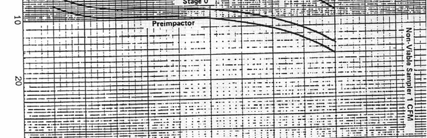
14 Figure 6: Fractional Efficiency Curves 12


15 Figure 7: Particle Size Diameter Graph 13
16 F. CALIBRATION Since the size fraction for each stage is determined by the orifice velocities, it is important that the sampler be operated at 1 ACFM. For this reason, the unit should be periodically re-calibrated and whenever non-standard temperatures and pressures are encountered, calibration should be performed at the sampling conditions. Do not use rubber tubing of smaller diameter or length different than that supplied with the impactor unless the flow rate is readjusted. Each pump is equipped with an adjustable valve. Typically, the valve knob is removed after calibration to prevent unauthorized adjustment. Each pump-impactor assembly should be calibrated at the local environment upon receipt. In order to recalibrate at the local sampling environment, the following procedure is recommended: Place a calibrated dry gas meter upstream from the impactor. Attach a short 1 I.D. hose with approximately 1/4 wall to the inlet cone of the impactor and the other end to the outlet of the dry gas meter. Adjust the pump valve until 1 ACFM is being drawn through the impactor over a three minute test period as determined with an accurate stop watch. After maintaining 1 ACFM for three minutes, tighten the lock nut on the adjustment valve. Because of the 1.4 ACFM free flow rating of the motor/pump, up to 50-feet of tubing can be used between the impactor and the pump while still maintaining 1 ACFM through the actual impactor. Please find the following additional instructions if a 12 Volt pump will be used: 12 Volt Pump Operation: Battery required 12 Volt automotive-type, minimum 69 amp hour capacity. To operate properly: 1) Connect the clip of the red shielded pump wire to positive (+ or red) battery terminal. 2) Connect the slip of the black shielded wire to negative (-) terminal. The pump should start immediately. 3) If the pump does not start, check the battery voltage. It should be not less than 12 volts under a light load and 13 volts under no load. 4) If the pump does not operate with a fully charged battery, check the battery clip connections and wires for poor connections. 5) Should the pump fail to operate after Steps 1 through 4 are completed, please refer to the original manufacturer s instructions. 6) The pumping rate of the 12 Volt D.C. pump will vary with voltage. Normal pump operation requires a current draw of approximately 11 amps. Continuous running in excess of 3-hours may result in reduced battery voltage and lower CFM through the impactor. 7) Fully recharge the battery between uses. 14
17 Figure 8: Exploded View of 8-Stage Impactor 15
18 G. 60 LITER PER MINUTE CONVERSION KIT The BGI Non-Viable Cascade Impactor was designed to operate at a flow rate of 1 CFM or 28.3 liters/minute. This yields cut-points in the range 0.4 to 9.0 µm. However present pharmacopoeia requirements dictate that in the case of Dry Powder Inhalers (DPIs), a flow rate should be used which creates a 4kPa pressure drop over the inhaler under test. The result is that in most cases a flow-rate higher than 28.3 liters/minute is required due to the high resistance that DPIs impose. When using the BGI Cascade Impactor at flow rates greater than 28.3 liters/minute, the cut-points become lower and the inter-stage discrimination is also reduced. For user convenience the 60 liter/minute conversion kit has been designed as a modification to the standard BGI Non-Viable Cascade Impactor, such that it can be operated at 60 liters/min while retaining, as near as possible, the same cut-points as with the unmodified impactor at 28.3 liters/minute. The empirical formula can still be used to determine cut-points close to 60 liters/min. WARNING: Some solvents form flammable vapor-air mixtures that could be ignited on passage through a vacuum pump. Appropriate precautions should be taken to ensure operator safety during test (e.g., alternative solvents, use of vapor traps, minimal pump operating times, etc.). COMPONENTS 1 Stage -0 1 Stage -1 1 Inter-Stage O ring 1 Collection Plate (with center hole) 1 Stage Visible Inspection Certificate ASSEMBLY To assemble the 60 liter/minute conversion kit and retrofit to existing assembled impactor: Place the O- ring for Stage -0 in the groove provided. Unclamp the impactor and remove Stage 7 (including collection plate) and Stage 0. Seat Stage -0 onto Stage 1 (in place of Stage 0). 16
19 Place the conversion kit collection plate (with center hole) on Stage -0. Seat Stage -1 on top of Stage -0. Re-clamp the impactor. The impactor should now consist of 8 stages, Stages -1 to 6. The collection plates should consist of three with holes for the top three stages and five without holes for the bottom five stages. CUT-POINTS The cut-points for the modified impactor were determined by experimental techniques; details of which are available on request. Cut-Points for Modified Impactor Shown Against Unmodified Impactor Unmodified Impactor (@ 28.3 liters/min) Modified Impactor (@60 liters/min) Stage Cut-Point (µm) Stage Cut-point (µm) Notes: 1. The modified BGI Cascade Impactor should be validated before use. 2. If a pre-separator is required, then a "high-top" version of the Pre-separator should be purchased for use with the 60 liter/min Conversion Kit. It is not recommend that the "standard" pre-separator be used with the 60 liter/min Conversion Kit, as this will give a cut-off point lower than that of Stage -1.
20 H. 90 LITER PER MINUTE CONVERSION KIT The BGI Cascade Impactor was designed to operate at a flow rate of 28.3 liters/minute (1CFM). This yields cut-points in the range 0.4 to 9.0 µm. However present pharmacopoeia requirements dictate that in the case of Dry Powder Inhalers (DPIs), a flow rate should be used which creates a 4kPa pressure drop over the inhaler under test. The result is that in most cases a flow-rate higher than 28.3 liters/minute is required due to the high resistance that DPIs impose. When using the BGI Non-Viable Impactor at flow rates greater than 28.3 liters/minute, the cut-points become lower and the inter-stage discrimination is also reduced. For user convenience the 90 liter/minute conversion kit has been designed as a modification to the standard BGI Cascade Impactor, such that it can be operated at 90 liters/min while retaining, as near as possible, the same cut-points as with the unmodified impactor at 28.3 liters/minute. The empirical formula can still be used to determine cut-points close to 90 liters/min. WARNING: Some solvents form flammable vapor-air mixtures that could be ignited on passage through a vacuum pump. Appropriate precautions should be taken to ensure operator safety during test (e.g., alternative solvents, use of vapor traps, minimal pump operating times, etc.). COMPONENTS 1 Stage -0 1 Stage -1 1 Stage -2 2 Inter-Stage O ring 2 Collection Plate (with center hole) 1 Stage Visual Insptection Certificate ASSEMBLY To assemble the 90 liter/minute conversion kit and retrofit to existing assembled impactor: Place an 'O' ring for Stage -0 in the groove provided. Place an 'O' ring for Stage -1 in the groove provided. Unclamp the impactor and remove Stage 6, Stage 7 and Stage 0 (including collection plates). 18
21 Seat Stage -0 onto Stage 1 (in place of Stage 0). Place a conversion kit collection plate (with center hole) on Stage -0. Seat Stage -1 on top of Stage -0. Place a conversion kit collection plate (with center hole) on Stage -1. Seat Stage -2 on top of Stage -1. Re-clamp the impactor. The impactor should now consist of 8 stages, Stages -2 to 5. The collection plates should consist of four with holes for the top four stages and four without holes for the bottom four stages. CUT-POINTS The cut-points for the modified impactor were determined by experimental techniques; details of which are available on request. Cut-Points for Modified Impactor Shown Against Unmodified Impactor Unmodified Impactor (@ 28.3 liters/min) Modified Impactor (@90 liters/min) Stage Cut-Point (µm) Stage Cut-point (µm) Notes: 1. The modified BGI Non-Viable Cascade Impactor should be validated before use. 2. It is not recommend that the "standard" pre-separator be used with the 90 liter/min Conversion Kit, as this will give a cut-off point lower than that of Stage -1.
22 I. CLEANING METHOD FOR 8 STAGE NON-VIABLE IMPACTORS (USING AN ULTRASONIC CLEANING SYSTEM) 1. Fill the tank of the Ultrasonic Cleaning System with clean water. Note: Never allow the liquid level to drop below 25mm from the top of the tank. 2. Add a cap full of cleaning agent (typically Ambersil Aquasafe, Nutracon etc providing that the cleaning detergent has neutral ph) to the tank. The manufacturer s dilution instructions must be followed. 3. Heat the tank to approximately 50 C to 60 C. 4. (Rinse with an organic solvent if required). Place the dismantled impactor stages into a suitable rack/basket to separate them during the cleaning process and also to allow the maximum surface area of the plate to be exposed to the liquid in the tank. 5. Lower the rack/basket holding the impactor stages into the tank. 6. Switch on the Ultrasonic facility for 5 minutes for stages 0-4; -2, -1 and -0; and for a maximum of 2 minutes for stages Switch off the Ultrasonic facility and remove the impactor stages from the tank. 8. Wash all the stages in clean cold water. 9. Remove surplus water from the stages with clean compressed air. 10. Place the stages into a Heater Cabinet set to approximately 35 C to 40 C and leave for at least 30 minutes. 11. If any holes still appear not to be clean or clear, then use a clean, soft-haired brush with warm water with detergent to remove any further contaminant. Repeat steps 4 through 10 inclusive for these stages. 12. DO NOT at any time soak the impactor stages for long periods in any solvent or aqueous media. Revision History V Text Created November,
Series Instruction Manual
 Series 10-800 Instruction Manual Six and Two Stage Viable Samplers Part Number 100072-00 29Oct2009 2007 Thermo Fisher Scientific Inc. All rights reserved. Specifications, terms and pricing are subject
BioAerosol Nebulizing Generator. Operation and Maintenance User Manual
 BioAerosol Nebulizing Generator Operation and Maintenance User Manual INTRODUCTION The BANG or BioAerosol Nebulizing Generator is a unique nebulizer for the generation of aqueous aerosols at a low air
OPERATING INSTRUCTIONS
 OPERATING INSTRUCTIONS Tempe Pressure Cell June 1995 Fig. 1a 1400 Tempe Pressure Cells with 3cm cylinders and 6cm cylinders) mounted on the Tempe Cell Stand Fig. 1b Disassembled 1400 Tempe Pressure Cell
The Discussion of this exercise covers the following points:
 Exercise 3-2 Orifice Plates EXERCISE OBJECTIVE In this exercise, you will study how differential pressure flowmeters operate. You will describe the relationship between the flow rate and the pressure drop
Model VR6 System. Installation, Operation & Maintenance
 Model VR6 System Installation, Operation & Maintenance General: All Archer Instruments chlorination systems are carefully designed and tested for years of safe, accurate field service. All Archer Instruments
OPERATOR S MANUAL Ar-Gone Weld Gas Analyzer
 July 2011 OPERATOR S MANUAL Ar-Gone Weld Gas Analyzer WARNING! Before operating this product, read and understand this Operator s Manual. Become familiar with the potential hazards of this unit. Contact
Parallel Particle Impactors New Personal Samplers for Accurate Assessment of Worker Exposure to Respirable or Thoracic Dust
 Parallel Particle Impactors New Personal Samplers for Accurate Assessment of Worker Exposure to Respirable or Thoracic Dust Saulius Trakumas, Peter M. Hall, and Donald L. Smith SKC Inc., Eighty Four, Pennsylvania
Instruction Manual Updated 7/26/2011 Ver. 2.2
 4-Unit Model MB HTHP Filter Press #171-50-4: 115-Volt #171-51-4: 230-Volt Instruction Manual Updated 7/26/2011 Ver. 2.2 OFI Testing Equipment, Inc. 11302 Steeplecrest Dr. Houston, Texas 77065 U.S.A. Tele:
Series 290. Instruction Manual Marple Personal Cascade Impactors Part Number Oct2009
 Series 290 Instruction Manual Marple Personal Cascade Impactors Part Number 100065-00 31Oct2009 2007 Thermo Fisher Scientific Inc. All rights reserved. Specifications, terms and pricing are subject to
Model PSI Compressor with 3-Gallon Air Tank 12VDC
 Model 6350 150 PSI Compressor with 3-Gallon Air Tank 12VDC IMPORTANT: It is essential that you and any other operator of this product read and understandd the contents of this manual before installing
Predicted Dispense Volume vs. Gravimetric Measurement for the MICROLAB 600. November 2010
 Predicted Dispense Volume vs. Gravimetric Measurement for the MICROLAB 600 November 2010 Table of Contents ``Abstract...3 ``Introduction...4 ``Methods & Results...6 ``Data Analysis...9 ``Conclusion...12
Operating instructions Pitot Static Tube
 Operating instructions Pitot Static Tube halstrup-walcher GmbH Stegener Straße 10 D-79199 Kirchzarten, Germany Phone: +49 (0) 76 61/39 63-0 Fax: +49 (0) 76 61/39 63-99 E-mail: info@halstrup-walcher.de
LOW PRESSURE EFFUSION OF GASES revised by Igor Bolotin 03/05/12
 LOW PRESSURE EFFUSION OF GASES revised by Igor Bolotin 03/05/ This experiment will introduce you to the kinetic properties of low-pressure gases. You will make observations on the rates with which selected
12S 1st Stage. -Maintenance Procedure-
 12S 1st Stage -Maintenance Procedure- 1 Warning! All maintenance and repair procedures MUST be performed by a Mares authorized Service Center and/or Distributor. Therefore, the information provided below
Welker Sampler. Model GSS-1. Installation, Operation, and Maintenance Manual
 Installation, Operation, and Maintenance Manual Welker Sampler Model GSS-1 The information in this manual has been carefully checked for accuracy and is intended to be used as a guide to operations. Correct
Exercise 2-3. Flow Rate and Velocity EXERCISE OBJECTIVE C C C
 Exercise 2-3 EXERCISE OBJECTIVE C C C To describe the operation of a flow control valve; To establish the relationship between flow rate and velocity; To operate meter-in, meter-out, and bypass flow control
Columbus Instruments
 0215-003M Portable O 2 /CO 2 /CH 4 Meter User s Manual Columbus Instruments 950 NORTH HAGUE AVENUE TEL:(614) 276-0861 COLUMBUS, OHIO 43204, USA FAX:(614) 276-0529 1 www.colinst.com TOLL FREE 1-800-669-5011
Laboratory Hardware. Custom Gas Chromatography Solutions WASSON - ECE INSTRUMENTATION. Engineered Solutions, Guaranteed Results.
 Laboratory Hardware Custom Gas Chromatography Solutions Engineered Solutions, Guaranteed Results. WASSON - ECE INSTRUMENTATION Laboratory Hardware Wasson-ECE Instrumentation offers hardware-only solutions
Experiment 8: Minor Losses
 Experiment 8: Minor Losses Purpose: To determine the loss factors for flow through a range of pipe fittings including bends, a contraction, an enlargement and a gate-valve. Introduction: Energy losses
BACK PRESSURE / SUSTAINING
 In many liquid piping systems, it is vital that line pressure is maintained within relatively narrow limits. This is the function of the 108 Pressure Relief / Back Pressure Series of the OCV control valves.
Entry to these spaces must be rigorously controlled to prevent serious injury or death.
 Chapter 6 - Confined Spaces Chapter 6 Confined Spaces Definitions A confined space is defined as any structure that must be entered and that has or may contain dangerous concentrations of hazardous gases
Laboratory Hardware. Custom Gas Chromatography Solutions WASSON - ECE INSTRUMENTATION. Custom solutions for your analytical needs.
 Laboratory Hardware Custom Gas Chromatography Solutions Custom solutions for your analytical needs. Laboratory Hardware Wasson-ECE Instrumentation offers hardware-only solutions for advanced chromatography
Lab 3 Introduction to Quantitative Analysis: Pumps and Measurements of Flow
 Georgia Institute of Technology School of Earth and Atmospheric Sciences EAS 4641, Spring 2008 Lab 3 Introduction to Quantitative Analysis: Pumps and Measurements of Flow Purpose of Lab 3: 1) To gain a
AIR/OXYGEN BLENDER INSTRUCTION MANUAL
 BIO-MED DEVICES AIR/OXYGEN BLENDER INSTRUCTION MANUAL CATALOG #2120 REV 042203 BIO-MED DEVICES INC. 1445 BOSTON POST ROAD, GUILFORD, CT 06437 (203) 458-0202 FAX (203) 458-0440 www.biomeddevices.com TABLE
Met One E-BAM Particulate Monitor
 STANDARD OPERATING PROCEDURES Met One E-BAM Particulate Monitor AMBIENT AIR MONITORING PROGRAM for the 130 LIBERTY STREET DECONSTRUCTION PROJECT LOWER MANHATTAN DEVELOPMENT CORPORATION 1 Liberty Plaza
<788> PARTICULATE MATTER IN INJECTIONS
 PARTICULATE MATTER IN INJECTIONS This general chapter is harmonized with the corresponding texts of the European Pharmacopoeia and/or the Japanese Pharmacopoeia. These pharmacopeias have undertaken
200 PSI HIGH-FLOW AIR SOURCE KIT
 200 PSI HIGH-FLOW AIR SOURCE KIT 50% Duty Compressor on 2.0 Gallon Air Tank PART NO. 20008 IMPORTANT: It is essential that you and any other operator of this product read and understand the contents of
Experiment. THE RELATIONSHIP BETWEEN VOLUME AND TEMPERATURE, i.e.,charles Law. By Dale A. Hammond, PhD, Brigham Young University Hawaii
 Experiment THE RELATIONSHIP BETWEEN VOLUME AND TEMPERATURE, i.e.,charles Law By Dale A. Hammond, PhD, Brigham Young University Hawaii The objectives of this experiment are to... LEARNING OBJECTIVES introduce
Multi-Probe Sampling System User Guide & Manual
 Multi-Probe Sampling System User Guide & Manual Rev. 06/05/12 Part #22200012 Table of Contents CHAPTER 1: SYSTEM DESCRIPTION... 2 FUNCTION AND THEORY... 3 SYSTEM COMPONENTS... 4 CHAPTER 2: SYSTEM INSTALLATION...
Lab Session #4 AN Physical Properties
 Lab Session #4 AN Physical Properties The main goal of this laboratory session is to provide a practical experience in the determination of the physical properties for AN and ANFO. The students will determine
Air permeance of paper and paperboard (Sheffield method)
") T 547 om-97 PROVISIONAL METHOD 1988 OFFICIAL METHOD 1997 1997 TAPPI The information and data contained in this document were prepared by a technical committee of the Association. The committee and the
T 547 om-97 PROVISIONAL METHOD 1988 OFFICIAL METHOD 1997 1997 TAPPI The information and data contained in this document were prepared by a technical committee of the Association. The committee and the
SERVICE MANUAL MODEL BA050BMST BREATHING AIR PANEL
 www.modsafe.com SERVICE MANUAL MODEL BA050BMST BREATHING AIR PANEL WARNING: Do not attempt to operate this equipment without first reading and understanding the service manual enclosed with this device.
Hodge Clemco Ltd. SG-300 Suction Gun. Owner s Manual. Hodge Clemco Ltd
 Page 1 of 10 Hodge Clemco Ltd SG-300 Suction Gun Date of issue: 24/08/92 TS.OM64A Owner s Manual Hodge Clemco Ltd Orgreave Drive Sheffield S13 9NR Tel: 0114 254 8811 Email sales@hodgeclemco.co.uk www.hodgeclemco.co.uk
Spray Gun 134-A. 1 Liter High- Pressure Gel Coat. Usage Instructions & Parts List
 1 Liter High- Pressure Gel Coat Spray Gun 134-A Usage Instructions & Parts List www.fibreglast.com 1.800.821.3283 385 Carr Drive Brookville, OH 45309 Operating Instructions & Suggestions This is a high
Discontinued. Powers Controls. Technical Instructions Document No P25 RV Rev. 1, May, RV 201 Pressure Reducing Valves.
 Powers Controls RV 201 Pressure Reducing Valves Description Features Product Numbers Dual Pressure PRV Technical Instructions Document No. 155-049P25 RV 201-1 Single Pressure PRV The RV 201 Pressure Reducing
Phalanx Alpha Phalanx Beta and Ultra Elite
 Phalanx Alpha Phalanx Beta and Ultra Elite riot control agent gas masks instructions parts list NIOSH approved for respiratory protection in atmospheres containing CN and CS and particulates under the
Cover Page for Lab Report Group Portion. Pump Performance
 Cover Page for Lab Report Group Portion Pump Performance Prepared by Professor J. M. Cimbala, Penn State University Latest revision: 02 March 2012 Name 1: Name 2: Name 3: [Name 4: ] Date: Section number:
CORESTA RECOMMENDED METHOD N 6
 CORESTA RECOMMENDED METHOD N 6 DETERMINATION OF VENTILATION DEFINITIONS AND MEASUREMENT PRINCIPLES (2015 Revision September 2016) 1. SCOPE This CORESTA Recommended Method specifies a method for the determination
RADIATION PROCEDURES MANUAL Procedure Cover Sheet
 RADIATION PROCEDURES MANUAL Procedure Cover Sheet Procedure Title: Calibration of Eberline Portable Particulate Noble Gas Monitor Procedure Number: TSO-08-13-REV 1 Effective Date: July 1, 2008 Approved
Model: AT-1000 L.P.G. FREEZE VALVE
 Model: AT-1000 P/N: 2156006200 3829 Forest Parkway Suite 500 Wheatfield, NY 14120-3763 Phone: 716-629-3802 Fax: 716-693-9162 solutions@viatran.com www.viatran.com 1 OPERATION AND MAINTENANCE INSTRUCTIONS
Service and Repair Manual
 II stage R2 Ice/ Special, II stage R 1 Pro DOWNSTREAM 2 nd STAGE REGULATOR Service and Repair Manual Introduction Safety Precautions...4 General Procedures, Maintenance Schedules...5 Initial Inspection
Instruction and Maintenance Manual
 Instruction and Maintenance Manual GRYF OXY ZM 02/100/2 E Contact GRYF HB, spol. s r.o. Cechova 314 Havlickuv Brod 580 01 tel.: +420 569 426 627 fax: +420 569 426 627 www.gryf.eu ver.: 11.2.2015 OEM module
CONGRATULATIONS ON YOUR PURCHASE OF YOUR THUNDER COMPRESSOR For your personal safety please read, understand and follow the information provided in
 CONGRATULATIONS ON YOUR PURCHASE OF YOUR THUNDER COMPRESSOR For your personal safety please read, understand and follow the information provided in this instruction manual. 1 CONTENTS 3. Safety Precautions
SERVICE MANUAL MODEL BA100BMST 100 SCFM PORTABLE AIR PANEL
 Product Manual MST Portable Air Filtration System SERVICE MANUAL MODEL BA100BMST 100 SCFM PORTABLE AIR PANEL WARNING: Do not attempt to operate this equipment without first reading and understanding the
Cover Page for Lab Report Group Portion. Head Losses in Pipes
 Cover Page for Lab Report Group Portion Head Losses in Pipes Prepared by Professor J. M. Cimbala, Penn State University Latest revision: 02 February 2012 Name 1: Name 2: Name 3: [Name 4: ] Date: Section
BACK PRESSURE / SUSTAINING
 SPECIFICATIONS DIMENSIONS In many liquid piping systems, it is vital that line pressure is maintained within relatively narrow limits. This is the function of the 108 Pressure Relief / Back Pressure Series
450P AUTOMATIC PORTABLE COMPRESSOR EXTREME SERIES
 EXTREME SERIES PART NO. 45043 IMPORTANT: It is essential that you and any other operator of this product read and understand the contents of this manual before installing and using this product. SAVE THIS
E3628 THE RESPIRATORY PROTECTION PROGRAM: EMPLOYEE TRAINING. Leader s Guide ERI Safety Videos EMPLOYEE TRAINING
 E3628 THE RESPIRATORY PROTECTION PROGRAM: EMPLOYEE TRAINING Leader s Guide 2007 ERI Safety Videos THE RESPIRATORY PROTECTION PROGRAM: EMPLOYEE TRAINING This easy-to-use Leader s Guide is provided to assist
SAPAG. Safety valves, type 5700 Storage, Use, Operation and Maintenance Instructions. IMPORTANT NOTICE
 SAPAG IMPORTANT NOTICE Contents Important notice 1 0 Valve identification 2 1 Storage 2 2 Installation 2 3 Operation 2 4 Maintenance 3 4.1 Dismantling 3 4.2 Inspection 3 4.3 Repair 3 4.4 Assembly 4 4.5
The Ideal Gas Constant
 Chem 2115 Experiment # 8 The Ideal Gas Constant OBJECTIVE: This experiment is designed to provide experience in gas handling methods and experimental insight into the relationships between pressure, volume,
Vision Painting Inc Safety Management System
 Abrasive Blasting 1. PURPOSE The purpose of this program is to provide training and qualification guidelines for the safe operation of Abrasive Blasting. The Safety Officer is responsible for facilitating
Biography. Abstract. Keywords. Body box, garments, validation, calibration, clean garments, IEST-RP-CC003.3, garment. Introduction and Scope
 NEW METHOD CALIBRATION FOR CALIBRATION OF A BODY BOX [Paper presented at IEST s ESTECH 2003 Conference, Phoenix, AZ, May 18-21] Rajan Jaisinghani, Technovation Systems, Inc. Biography Rajan (Raj) Jaisinghani
UP-F Delrin TM Winged Nut. UP-F PEEK TM Nut. with F-142 PEEK TM Ferrule
 One Piece or Two? A one-piece fitting is more convenient and less cumbersome, since the ferrule cannot stick in a receiving port and the fitting is more easily found if dropped. With two-piece Fingertight,
Oxygen Contamination
 MPMS Application Note 1014-210 Oxygen Contamination This application note describes potential sources for oxygen contamination in the sample chamber and discusses its possible effects. Molecular oxygen,
Model: AT-1000 L.P.G. FREEZE VALVE
 Model: AT-1000 P/N: 2156006200 3829 Forest Parkway Suite 500 Wheatfield, NY 14120-3763 Phone: 716-629-3802 Fax: 716-693-9162 solutions@viatran.com www.viatran.com 1 OPERATION AND MAINTENANCE INSTRUCTIONS
420C AIR COMPRESSOR KIT PART NO C AIR COMPRESSOR KIT PART NO
 420C AIR COMPRESSOR KIT PART NO. 42042 460C AIR COMPRESSOR KIT PART NO. 46043 420C 460C IMPORTANT: It is essential that you and any other operator of this product read and understand the contents of this
Tel: FAX: Risk Assessment for Exposure to Respirable Dusts Generated from the Use of Chalks and Pastels
 Duke University Medical Center Department of Community & Family Medicine Division of Occupational & Environmental Medicine Box 3834 Duke University Medical Center Durham, NC 27710 April 26, 2003 Risk Assessment
AIR-OPERATED DOUBLE DIAPHRAGM PUMP USER S MANUAL
 00, 0, 000 00, 000, 00 A. TECHNICAL INFORMATION Model 00 Inlet/Outlet " Air Inlet /" 0 / 000 /" /" 00 /" /" 000 /" /" 00 /" /" Flow Rate GPM/ 0LPM GPM/ 0LPM GPM/ LPM GPM/ LPM GPM/ 0LPM GPM/ 0LPM Maximum
Purge Star & Ring Purge Systems
 March 2013 Operator s Manual Purge Star & Ring Purge Systems Additional instruction for Purge Star Single Hose, Purge Star Double (bypass) Hose and Ring Purge with bypass hose and gas dump valve feature.
Level MEASUREMENT 1/2016
 Level MEASUREMENT 1/2016 AGENDA 2 A. Introduction B. Float method C. Displacer method D. Hydrostatic pressure method E. Capacitance method G. Ultrasonic method H. Radar method I. Laser method J. Level
INSTRUMENTS A THERMAL MASS FLOW SENSOR USING A CONSTANT DIFFERENTIAL TEMPERATURE ABOVE THE AMBIENT GAS TEMPERATURE
 TELEDYNE HASTINGS TECHNICAL PAPERS INSTRUMENTS A THERMAL MASS FLOW SENSOR USING A CONSTANT DIFFERENTIAL TEMPERATURE ABOVE THE AMBIENT GAS TEMPERATURE Proceedings of FEDSM 98 1998 ASME Fluids Engineering
200 PSI COMPRESSORS - MODEL NUMBERS
 200 PSI COMPRESSORS - MODEL NUMBERS 380C AIR COMPRESSOR KIT PART NO. 38033 480C AIR COMPRESSOR KIT PART NO. 48043 380C 480C IMPORTANT: It is essential that you and any other operator of this product read
LOW PRESSURE EFFUSION OF GASES adapted by Luke Hanley and Mike Trenary
 ADH 1/7/014 LOW PRESSURE EFFUSION OF GASES adapted by Luke Hanley and Mike Trenary This experiment will introduce you to the kinetic properties of low-pressure gases. You will make observations on the
INDUSTRIAL - SOLVENT PARTS CLEANER
 INDUSTRIAL - SOLVENT PARTS CLEANER OPERATION & INSTRUCTION MANUAL I. Introduction A. Manufacturer s Statement CM400 This manual will provide you with important information about the Solvent Parts Cleaners
SAFETY MANUAL FOR FLAMMABLE PRODUCT TRANSFER
 SAFETY MANUAL FOR FLAMMABLE PRODUCT TRANSFER SUPPLIMENT TO eom IMPORTANT READ THIS MANUAL BEFORE PRODUCT INSTALLATION, OPERATION, INSPECTION & MAINTENANCE Tougher and more rigid guidelines are being established
Installation, Operation, and Maintenance Manual
 Installation, Operation, and Maintenance Manual Welker The information in this manual has been carefully checked for accuracy and is intended to be used as a guide for the installation, operation, and
100C Air Compressor Kit
 10010 100C Air Compressor (standard mounting bracket, CE Spec) 10014 100C Air Compressor (no leader hose or check valve, CE Spec) 10016 100C Air Compressor (with Omega Bracket, CE Spec) IMPORTANT: It is
SERVICE MANUAL MODEL BA020AMST BREATHING AIR PANEL
 SERVICE MANUAL MODEL BA020AMST BREATHING AIR PANEL WARNING: Do not attempt to operate this equipment without first reading and understanding the service manual enclosed with this device. 5/08 2 GENERAL
Mass Spec will not Autotune
 Mass Spec will not Autotune Applies to 5973A/N MSD What could be the problem? There could be several things that would cause your Mass Spec not to Autotune. The most common, easily corrected Autotune problems
METHOD 21 - DETERMINATION OF VOLATILE ORGANIC COMPOUND LEAKS. 1.2 Scope. This method is applicable for the
 1151 METHOD 21 - DETERMINATION OF VOLATILE ORGANIC COMPOUND LEAKS 1.0 Scope and Application. 1.1 Analytes. Analyte Volatile Organic Compounds (VOC) CAS No. No CAS number assigned 1.2 Scope. This method
CTG Certification Protocol -- Version 3.0 SUMMARY
 Date of Test: Test Report Number: SUMMARY Date of Prior Certification: Certified by: Re-certification Due Date: Unit Description: Make : Model: Serial Number: Location: CERTIFIER INFORMATION Name: Client
COMPUTATIONAL FLOW MODEL OF WESTFALL'S LEADING TAB FLOW CONDITIONER AGM-09-R-08 Rev. B. By Kimbal A. Hall, PE
 COMPUTATIONAL FLOW MODEL OF WESTFALL'S LEADING TAB FLOW CONDITIONER AGM-09-R-08 Rev. B By Kimbal A. Hall, PE Submitted to: WESTFALL MANUFACTURING COMPANY September 2009 ALDEN RESEARCH LABORATORY, INC.
SERVICE MANUAL MODEL BA600AMST-S1 BREATHING AIR PANEL
 SERVICE MANUAL MODEL BA600AMST-S1 BREATHING AIR PANEL WARNING: Do not attempt to operate this equipment without first reading and understanding the service manual enclosed with this device. 2/05 GENERAL
Model Series 62 Constant Differential Relay
 Siemens Industry, Inc. INSTALLATION AND SERVICE INSTRUCTION INTRODUCTION Model Series 62 Constant Differential Relay Rev 11 March 2011 Supersedes Rev 10 The Constant Differential Relay maintains a constant
PumpAgents.com - Click here for Pricing/Ordering Nominal psi (bar) Cut-In Cut-Out
 Cut-In Cut-Out") PumpAgents.com - Click here for Pricing/Ordering Model 31670-Series Dual Max 7.5 GPM (28 LPM) AUTOMATIC TWO STAGE WATER SYSTEM WITH ACCUMULATOR TANK AND PUMPGARD STRAINER IDEAL FOR PLEASURE AND COMMERCIAL
PumpAgents.com - Click here for Pricing/Ordering Model 31670-Series Dual Max 7.5 GPM (28 LPM) AUTOMATIC TWO STAGE WATER SYSTEM WITH ACCUMULATOR TANK AND PUMPGARD STRAINER IDEAL FOR PLEASURE AND COMMERCIAL
IMPORTANT SAFETY INSTRUCTIONS
 IMPORTANT SAFETY INSTRUCTIONS CAUTION - To reduce risk of electrical shock: - Do not disassemble. Do not attempt repairs or modifications. Refer to qualified service agencies for all service and repairs.
200 PSI FAST-FILL AIR SOURCE KIT
 200 PSI FAST-FILL AIR SOURCE KIT 55% Duty Compressor on 2.0 Gallon Air Tank PART NO. 20007 IMPORTANT: It is essential that you and any other operator of this product read and understand the contents of
UsER manual for Watersens ph -REDOX
 UsER manual for Watersens -REDOX Cl 8 1 2 6 3 3 7 7 4 4 4 4 Parts List 1 Redox Probe 1 x 2 PH Probe 1 x 5 Tube Weight 2 x 6 Connection Valve 1 x chlorine 3 Chlorine and Pumps 2 x 7 Dosing Valve 2 x 5 5
CentriFlow Meter Integrated Air Entrainment System
 CentriFlow Meter Integrated Air Entrainment System INSTALLATION & OPERATION MANUAL January 2004 Revision 021-4 EASTERN INSTRUMENTS 416 LANDMARK DR. WILMINGTON, NC 28412 910-392-2490 Fax: 910-392-2123 website:
Rate of Flow Valve Series 120
 SPECIFICATIONS Rate of Flow Valve Series DIMENSIONS The OCV Series 120 Rate of Flow control valve is designed to control or limit flow to a predetermined rate, regardless offl uctuations in downstream
Air Eliminators and Combination Air Eliminators Strainers
 Description Air Eliminators and Combination Air Eliminator Strainers are designed to provide separation, elimination and prevention of air in piping systems for a variety of installations and conditions.
STANDARD OPERATING PROCEDURES
 PAGE: 1 of 9 CONTENTS 1.0 SCOPE AND APPLICATION 2.0 METHOD SUMMARY 3.0 SAMPLE PRESERVATION, CONTAINERS, HANDLING AND STORAGE 3.1 Canister Receipt 3.2 Canister Storage 4.0 INTERFERENCE AND POTENTIAL PROBLEMS
97C COMPRESSOR KIT 12V PART NO C COMPRESSOR KIT 24V PART NO C COMPRESSOR KIT PART NO
 97C COMPRESSOR KIT 12V PART NO. 00097 97C COMPRESSOR KIT 24V PART NO. 02497 98C COMPRESSOR KIT PART NO. 00098 97C 98C IMPORTANT: It is essential that you and any other operator of this product read and
Instruction Manual 742 5/1/2009. Eclipse Ratio Regulators ES Series Version 1
 Instruction Manual 742 5/1/2009 Eclipse Ratio Regulators ES Series Version 1 Copyright Copyright 1997 by Eclipse, Inc. All rights reserved worldwide. This publication is protected by federal regulation
Instruction and Maintenance Manual
 Instruction and Maintenance Manual GRYF OXY Z 02/100/2 E Contact GRYF HB, spol. s r.o. Cechova 314 Havlickuv Brod 580 01 tel.: +420 569 426 627 fax: +420 569 426 627 Czech Republic www.gryf.eu Technical
250C-IG COMPRESSOR KIT 12V PART NO C-IG COMPRESSOR KIT 24V PART NO
 250C-IG COMPRESSOR KIT 12V PART NO. 25050 250C-IG COMPRESSOR KIT 24V PART NO. 25058 IMPORTANT: It is essential that you and any other operator of this product read and understand the contents of this manual
BS ml Bottle Sampling Unit
 BS500 500ml Bottle Sampling Unit User Guide www.mpfiltri.co.uk 200.307-EN Covers Model Numbers BS500 SAFETY WARNING Hydraulic systems contain dangerous fluids at high pressures and temperatures. Installation,
Operating Instructions
 Operating Instructions PRECISION AIR ENTRAINMENT METER Model: 34-3265 (CT-126A) TABLE OF CONTENTS I. GENERAL INFORMATION...1 II. RELATED USER DOCUMENTATION...2 FIGURE 1 -- AIR ENTRAINMENT METER...3 III.
Warner Instruments, Inc Dixwell Avenue, Hamden, CT (800) / (203) (203) fax
 / (203) (203) fax") DH-40i, Rev. 04.03.02 Micro-Incubation Platform For RC-40 Chambers Model DH-40i 1125 Dixwell Avenue, Hamden, CT 06514 (800) 599-4203 / (203) 776-0664 (203) 776-1278 - fax DH-40i, Rev. 04.03.02 Table of
DH-40i, Rev. 04.03.02 Micro-Incubation Platform For RC-40 Chambers Model DH-40i 1125 Dixwell Avenue, Hamden, CT 06514 (800) 599-4203 / (203) 776-0664 (203) 776-1278 - fax DH-40i, Rev. 04.03.02 Table of
Technical Information
 Technical Information Installation, Operation, Installation, Operation and Maintenance and Maintenance Manual Manual Balston Model 75700-K728 Nitrogen Generator Figure 1-75700-K728 Overall Dimensions These
Installation, Operation, and Maintenance Manual. Welker Constant Pressure Cylinder With Solid Indicator (Non-mixer) Model CP-30SI
 Model CP-30SI") Installation, Operation, and Maintenance Manual Welker Constant Pressure Cylinder With Solid Indicator (Non-mixer) Model The information in this manual has been carefully checked for accuracy and is intended
Installation, Operation, and Maintenance Manual Welker Constant Pressure Cylinder With Solid Indicator (Non-mixer) Model The information in this manual has been carefully checked for accuracy and is intended
Applications of a Magnetic Sector Process Mass Spectrometer to the Analysis of Variable Vacuum Samples
 Applications of a Magnetic Sector Process Mass Spectrometer to the Analysis of Variable Vacuum Samples Outline of Presentation Introduction Process Gas Analysis Magnetic Sector Mass Spectrometer Standard
BGI, INC. WALTHAM, MA 02451
 BGI, INC. WALTHAM, MA 02451 JANUARY, 2002 58 Guinan Street Waltham, MA 02451 Tel: 781-891-9380 Fax: 781-891-8151 - - - - - - - - - - - - - - - - - - - - - - - - - - - - - - - - - - - - - - - - - - - -
Another convenient term is gauge pressure, which is a pressure measured above barometric pressure.
 VACUUM Theory and Applications Vacuum may be defined as the complete emptiness of a given volume. It is impossible to obtain a perfect vacuum, but it is possible to obtain a level of vacuum, defined as
GILMONT ACCUCAL FLOWMETERS
 OPERATING MANUAL GILMONT ACCUCAL FLOWMETERS 28W092 Commercial Ave. Barrington, IL U.S.A. 60010-2392 (847) 381-4888 (847) 381-7053 (Fax) 800-962-7142 www.barnant.com e-mail: barnant@barnant.com A-1299-0766
PENETRATION OF N95 FILTERING- FACEPIECE RESPIRATORS BY CHARGED AND CHARGE- NEUTRALIZED NANOPARTICLES
 PENETRATION OF N95 FILTERING- FACEPIECE RESPIRATORS BY CHARGED AND CHARGE- NEUTRALIZED NANOPARTICLES APPLICATION NOTE RFT-007 (US) by Hee-Siew (Ryan) Han and Mark Prell March 4, 2010 Introduction Aerosol-based
ATD LB PRESSURE BLASTER INSTRUCTION MANUAL
 ATD-8402 90LB PRESSURE BLASTER INSTRUCTION MANUAL SAVE THESE INSTRUCTIONS SAFETY INSTRUCTIONS FOR SANDBLASTER 1. Before opening the tank release the air pressure on the sand tank. To do this, turn off
SERVICE MANUAL MODEL BA200AA-S1 BREATHING AIR PANEL
 SERVICE MANUAL MODEL BA200AA-S1 BREATHING AIR PANEL WARNING: Do not attempt to operate this equipment without first reading and understanding the service manual enclosed with this device. 1/00 2 GENERAL
SILICA EXPOSURE MEASUREMENT IN REAL-TIME FOR CONSTRUCTION
 SILICA EXPOSURE MEASUREMENT IN REAL-TIME FOR CONSTRUCTION APPLICATION NOTE EXPMN-023(A4) Frequently Asked Questions What is crystalline silica and why is it important to measure exposure? Silica is found
250C-IG COMPRESSOR KIT 12V PART NO C-IG COMPRESSOR KIT 24V PART NO
 250C-IG COMPRESSOR KIT 12V PART NO. 25050 250C-IG COMPRESSOR KIT 24V PART NO. 25058 IMPORTANT: It is essential that you and any other operator of this product read and understand the contents of this manual