Performance. Saturday, December 22, 2012
|
|
|
- Emory Bryan
- 5 years ago
- Views:
Transcription
1

2 V MCG TAKE-OFF PERFORMANCE Minimum control speed on ground, from which a sudden failure of the critical engine can be controlled by use of primary flight controls only, the other engine remaining at Takeoff power. The pilot s action: recover control of the aircraft, enable safe Takeoff continuation.


3 V MCA TAKE-OFF PERFORMANCE Minimum control speed in the air at which aircraft can be controlled either with a 5 0 maximum bank angle, or with zero yaw,... in case of failure of one engine, the other engine remaining at Takeoff power 5 0 max

4 V MU TAKE-OFF PERFORMANCE Minimum unstick speed is the lowest calibrated airspeed at and above which the aircraft can safely lift off the ground and continue the Takeoff without encountering critical conditions


5 V MU Limiting Speed What are these critical conditions? Insufficient lateral control may cause engine or wing to hit the ground. The necessary Angle Of Attack is too great cause the rear of the a/c can hit the ground.
6 V 1 TAKE-OFF PERFORMANCE It is not a decision speed, it is the maximum speed at which brakes should be applied Represented by "1" on the airspeed scale (or the V1 value when it is off the airspeed scale). Inserted manually through the MCDU by the crew. Displayed on the MCDU TAKEOFF page.

7 V 1 TAKE-OFF PERFORMANCE If I am aware of a failure after V 1 I MUST CONTIUE Take-off I am too fast to brake safely before the end of the stop way V 1 V Speed
8 V R TAKE-OFF PERFORMANCE The speed at which the pilot rotates in order to reach V2 at an altitude of 35 feet at the latest after an engine failure. Inserted manually through the MCDU by the crew. Displayed on the MCDU TAKEOFF page.
9 V 2 TAKE-OFF PERFORMANCE Take-off climb speed Take-off safety speed that the aircraft attains at the latest at an altitude of 35 feet with one engine failed and maintains during the second segment of the take-off represented by the SPEED SELECT symbol on the speed scale
10 V 2 TAKE-OFF PERFORMANCE Minimum value equal to 1.13 VS for the corresponding configuration Inserted manually through the MCDU by the crew or automatically calculated by the computer and checked by the crew Displayed on the MCDU TAKE-OFF page and speed scale of the PFD
11 Screen height It is height where V2 must be reached above T/O surface after an engine failure at V1, the value of this height is 35 ft on dry runway and 15 ft on wet Climb gradient TAKE-OFF PERFORMANCE The net flight path achieved In term of percent. Height obtained in relation to ground distance covered
12
13 TAKE-OFF PERFORMANCE Take-off Lengths Runway Rigid or flexible rectangular area made of concrete or asphalt used for Take-off and landing


14 TAKE-OFF PERFORMANCE Stop way Rectangular area beyond the Take-off runway - Centered on the same (center) line, at least as wide as the runway - Designated by the airport authorities for use in decelerating the aircraft in case of aborted Take-off
15 TAKE-OFF PERFORMANCE Clear way Rectangular area beyond the Take-off runway 500 ft min Rectangular area beyond the runway, located on the same centerline, and under control of the airport authorities featuring Minimum width: 500 ft, Slope < 1.25 % % ma
16 TAKE-OFF PERFORMANCE Take-off Distance Available It is the Runway + clear way lengths TODA Take-Off Distance Available
17 TAKE-OFF PERFORMANCE Take-off Distance All Engines Operating (TOD) All Engines Operating V % V 1 V R VLOF 35 ft TOD
18 All Engines Operating TAKE-OFF PERFORMANCE Take-off Distance One Engine Inoperative (TOD) One Engine Inoperative TOD = from BR to 35 ft V 2 V EF V 1 V R V LOF 35 ft TOD
19 TAKE-OFF PERFORMANCE Take-off Run available It is the Runway length only TORA
20 TAKE-OFF PERFORMANCE Take-off Run Distance All Engine Operating (TORA) All Engines Operating + 15% V 2 V 1 V R V LOF 35 ft TORA // //
21 TAKE-OFF PERFORMANCE Take-off Run Distance One Engine Inoperative (TORA) All Engines Operating One Engine Inoperative TOR = from BR to middle point between Vlof and 35 ft V 2 V EF V 1 V R V LOF 35 ft TORA // //
22 TAKE-OFF PERFORMANCE Acceleration Stop Distance It is the Runway + Stop way length acceleration to V1 plus deceleration to full stop including any available stop way ASDA
23 TAKE-OFF PERFORMANCE Accelerate Stop Distance All Engine Operating (ASDA) All engines operating 2s Idle V 1 V= 0 ASDA
 One Engine Inoperative All engines operating 2s Idle V EF V 1 V= 0")
24 TAKE-OFF PERFORMANCE Accelerate Stop Distance One Engine inoperative (ASDA) One Engine Inoperative All engines operating 2s Idle V EF V 1 V= 0 ASDA
25 TAKE-OFF PERFORMANCE Balanced field length Where T/O distance equals accelerate stop not to exceed the length of the runway distance, Unbalanced field length Where T/O distance and acceleration stop are not equal (where clear way or stop way is used)
26 First segment TAKE-OFF PERFORMANCE Take-off Segments from end of T/O distance(35ft), to point where the landing gear fully retracted using T/O thrust & T/O flaps at constant V2 (positive climb) Second segment extends from the gear up point to height of 400 ft using T/O thrust & T/O flaps at constant V2 (2.4% climb gradient)
27 Third segment TAKE-OFF PERFORMANCE Take-off Segments the horizontal distance required to accelerate, at constant attitude using T/O thrust, to final climb speed while retracting flaps and slats ( 1.2% climb gradient ) Fourth segment extends from end of 3 rd segment to height 1500 ft (more if required by obstacle clearance) with flaps up, MCT & best angle climb speed (1.2% climb gradient )
28 ONE ENGINE OUT TAKE-OFF Trajectory Green dot (Min. Clean) 10 min after Take-off Take-off Distance MAXIMUM ACCELERATION HEIGHT End MINIMUM ACCELERATION HEIGHT 35 ft Green dot (Min. Clean) best lift-to-drag ratio V1 Segments: final
 air speed")

29 Performance TAKE-OFF Factors of Influence Wind and Moisture Effect on Take-off distances (TODA, TORA, ASDA) air speed wind Headwind ground speed Headwind shortens TO distances Only 50% must be taken into account, according to regulation.

30 Performance TAKE-OFF Factors of Influence air speed wind Tailwind Tailwind increases TO distances ground speed Regulation prescribes that 150% should be taken into account.
31 Runway wet or contaminated Regulation changes TOD: screen height = 15 ft TOR: it ends at V LOF 35 ft 15 ft TOR // // TOR
32 TAKE-OFF and RUNWAY slope Positive slope increases TO distances Runway slope It must not exceed ± 2 % ± 2 % Negative slope decreases TO distances


33 TAKE-OFF FLAPS Flaps increase lift - Reduces take-off distance C L Flaps increase drag - Decrease take-off gradient C D C L C D

34 Take-off Configurations Higher Flaps - Decreases Take-off distance - Decreases Tale-off Gradient Conf 1+F Flaps 5 Conf 2 Flaps 10 Conf 3 Flaps 15 TO distances are reduced. TO gradient decreases.


35 V 2 /V s Ratio Being limited by V S, V 2 is set through the V 2 /V S ratio. V 2 is the speed required when reaching 35 ft height. V 2 is determined by V R, as no TO parameters can be changed after lift off high V 2 high V R

36 V 2 /V s ratio High V 2 /V S Long TOD V 2 /V S influence: High ratio: long TOD high 2 nd segment slope Low ratio: short TOD low 2 nd segment slope V EF V 1 V R V LOF 35 ft High second segment gradient

37 Action speed V 1 Low V 1 implies short acceleration with all engines operating. The most penalizing conditions are taken into account the failure V EF occurs 1 second before V 1 Long TOD V EF V 1 V R V LOF 35 ft Short ASD
38 Action speed V 1 High V 1 means long acceleration with all engines operating. The most penalizing conditions are taken into account the failure (V EF) occurs 1 second before V 1. Short TOD V EF V 1 V R V LOF 35 ft Long ASD
39 Factors affecting maximum T/O weight A/C structure weight : max takeoff weight an A/C structure can sustain, set in A/C limitation Runway limit weight : - 115% all engine T/O distance - take distance with an engine failure - accelerate stop distance
40 Tire speed limit T/O weight : maximum allowable T/O weight limited by AFM maximum tire speed Factors affecting maximum T/O weight Brake energy limited T/O weight: maximum allowable T/O weight based on AFM maximum speed which produce maximum allowable brake energy for ambient condition in case of rejected T/O before V1
41 Climb limited T/O weight : Factors affecting maximum T/O weight maximum allowable T/O weight which fulfill minimum climb gradient requirement in the second segment, these requirements are based on the assumption of an engine failure at V1 Obstacle limit T/O weight : - gross gradient - net gradient
42 Gross gradient gross flight path actually flown as demonstrated by manufacturer, provided that the minimum gross gradient requirements by regulation are fulfilled Factors affecting maximum T/O weight Net gradient net flight path or net gradient are used to calculate maximum allowable T/O weight, satisfy minimum obstacle clearance required by regulations which equals (gross gradient 0.8%)
43 Takeoff optimization Obstacles To avoid an obstacle, you have different possibilities 35 ft TOD ASD Climb grad Flaps increases increases increases TO Weight decreases decreases increases V1 decreases increases no change V2 increases no change increases
44 Methods to calculate maximum T/O weight Improved climb The higher the take-off speeds, the better the climb gradient The improved climb weight is obtained by utilizing excess runway available to accelerate higher takeoff speeds thereby achieving higher gradient capability, which means higher T/O weights.
45 Methods to calculate maximum T/O weight Takeoff optimization is calculated for a given runway and its obstacles and for given conditions of flap setting, temperature, wind and QNH. The calculation produces a maximum permissible takeoff weight (or a maximum takeoff temperature for an actual weight).
46 Methods to calculate maximum T/O weight All the penalties and corrections due to different T/O conditions, runway condition forward CG, anti ice, are subtracted from the maximum permissible weight. Note It could be higher than the maximum structure weight in this case T/O is limited to maximum structure weight.
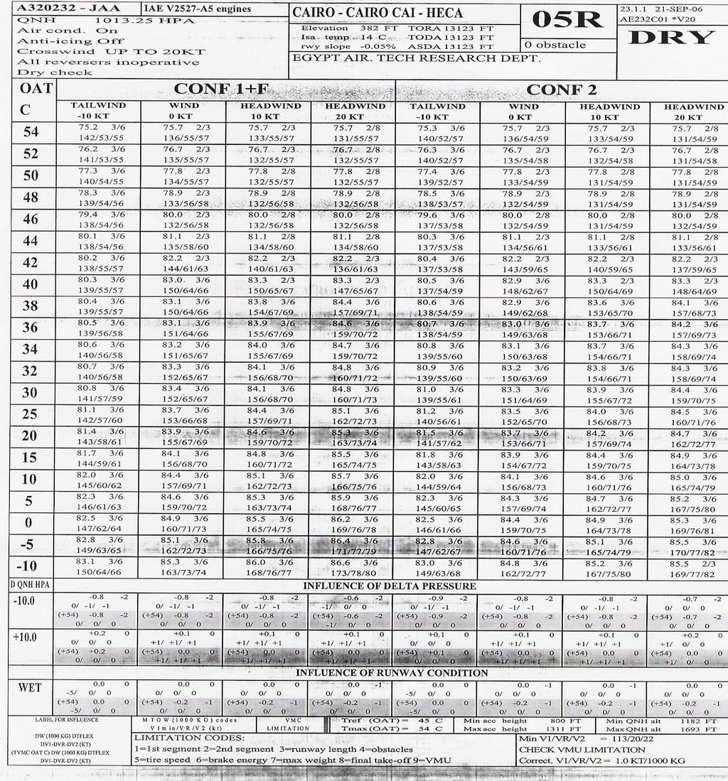
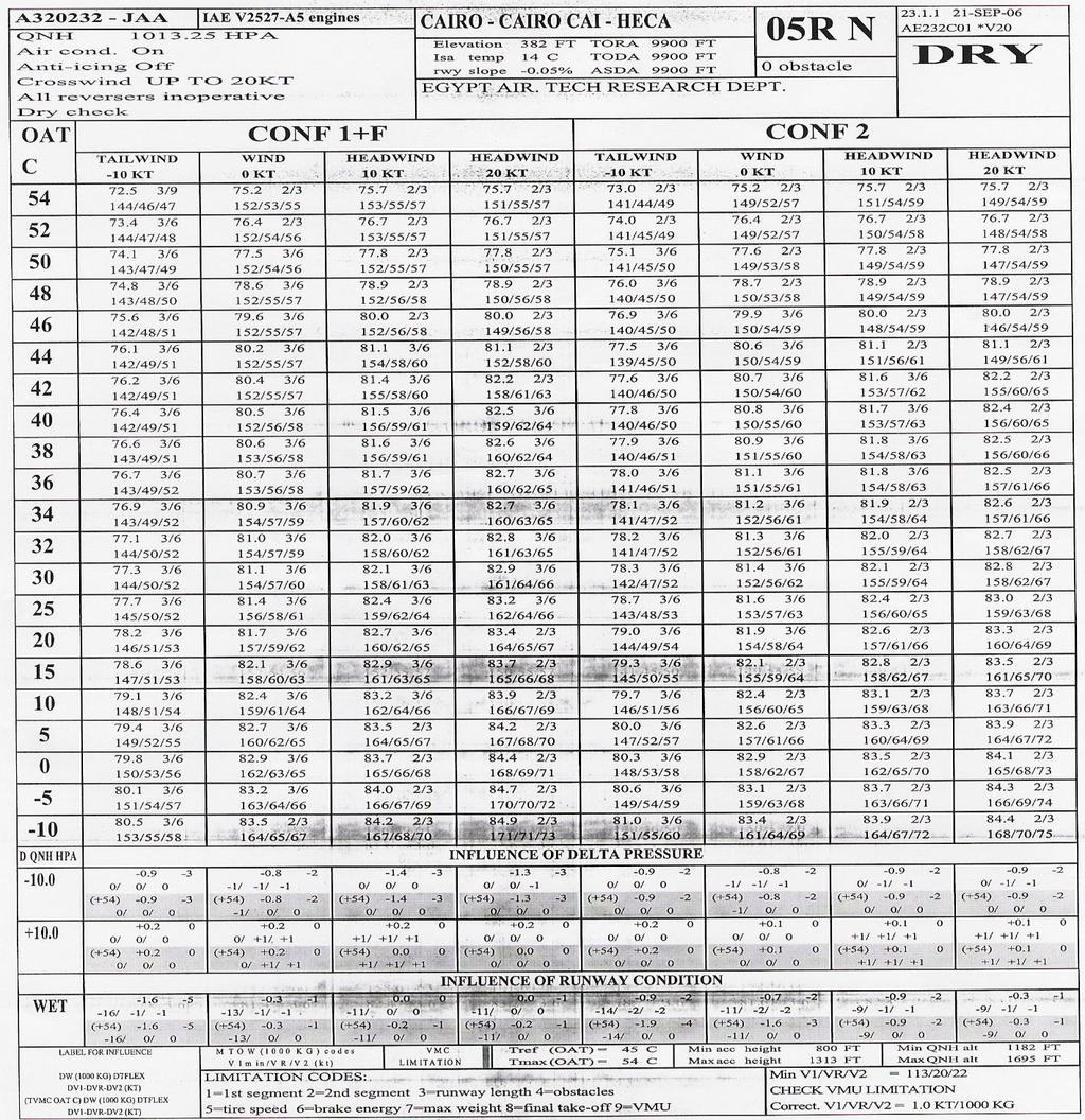
47 Charts to calculate maximum T/O weight QUICK REFERANCE TABLES RTOW CHARTS (located in A/C library) - Temperature entry - Weight entry OCTOPUS CHARTS These tables enable the crew to quickly determine the takeoff performance, at an airport for which no takeoff chart has been established. They are conservative
48 QUICK REFERANCE TABLES Disadvantages of these tables 1.Not covering for obstacles 2.Do not use quick reference tables in case of tailwind 3.Do not use quick reference tables in case of pressure altitudes above 2000 feet
49 QUICK REFERANCE TABLES A first table gives the corrections to be applied to the runway length for wind and runway slope. Nine other tables give, for three different pressure altitudes (0, 1000 and 2000 feet) and three configurations, The maximum takeoff weight, limitation codes and associated speeds as a function of temperature and corrected runway length. TREF and TMAX are given on the top of each table
50 QUICK REFERANCE TABLES Note Quick reference tables are established at V1 mean with air conditioning OFF and anti ice OFF HOW TO PROCEED Enter the first table with runway length, slope and wind data. Determine the corrected runway length by applying the corrections due to slope and wind
51 Corrections For Wind and Runway Slope Runway length (m) Effect of wind Effect of runway slope per knot of head wind add (meter) per percent uphill slope subtract (meters) per percent downhill slope add (meters)
52 QUICK REFERANCE TABLES Select the configuration as a function of this corrected runway length. Enter the table(s) corresponding to the configuration and airport pressure altitude. As far as airport pressure altitude is concerned, two methods may be applied
53 QUICK REFERANCE TABLES Interpolate the takeoff performance by using the two tables enclosing the airport pressure altitude For a more conservative figure, use the table corresponding to the pressure altitude immediately above the airport pressure altitude Enter the appropriate column of the table(s) with the corrected runway length
54 QUICK REFERANCE TABLES Once again, two methods may be applied: Interpolate the takeoff performance between the two columns enclosing the corrected runway length For more conservative figure, use the column corresponding to the shorter corrected runway length Determination of maximum takeoff weight. Enter the table(s) and column(s) with the actual OAT and read maximum takeoff weight, limitation codes, V1, VR and V2. If necessary interpolate weight and speeds
55 2 : second segment 3 : runway 5 : tire speed 6 : brake energy 8 : final take-off Note QUICK REFERANCE TABLES Limitation codes Limitation codes 1 (structural weight) and 4 (obstacles) do not appear in quick reference tables
56 RTOW today is kg Speed s
57 QUICK REFERANCE TABLES The determination of flexible temperature is possible only when there is no obstacle on the flight path Enter the table(s) and column(s) with the actual takeoff weight and read the corresponding temperature as flexible temperature
58 The net takeoff flight path and the associated weight decrement are conservative Performance QUICK REFERANCE TABLES How to determine reduction for obstacle Enter graphs to quickly determine the take-off performance out of an airport by positioning obstacles They must be used with the corresponding quick reference table so as to determine weight decrement and required gradient

59 Performance NET TAKE-OFF FLIGHT PATH Airbus chart Example
60 RTOW Charts Takeoff charts are required to provide performance at take-off It is possible to present the charts in two different ways of entry Temperature entry Temperature provided in the left column Weight entry Weight provided in the left column
61 Temperature Entry
62 Weight Entry The takeoff chart (RTOW : Regulatory Takeoff Weight) is calculated for a specific aircraft version and for a particular runway specified at the top of the chart. The top of the chart also gives some information about the runway and lists the calculation assumptions.
63 Weight Entry This allows the crew to select the configuration that gives either 1. The highest permissible take-off weight 2. For a given weight, the highest flexible temperature If different configurations give equivalent performance, the crew should select the configuration associated with the lowest take-off speeds
64 9.VMU Performance The available limitation codes are 1.First segment 2.Second segment 3.Runway length 4.Obstacles 5.Tire speed 6.Brake energy 7.Maximum computation weight 8.Final takeoff
65 TAKE-OFF CONDITIONS CORRECTIONS Each takeoff chart is computed for a given set of conditions (Air conditioning, QNH, anti ice...) specified at the top of the chart If the actual take-off conditions are different, the crew must apply corrections Conservative corrections on aircraft FCOW (to be used when not provided on the chart)
66 MTOW Determination Enter the chart with the first configuration and actual wind column reading the temperature value This temperature value stands for the OAT Read the maximum takeoff weight corresponding to the actual OAT Note That it is allowed to interpolate between two consecutive lines to obtain the maximum takeoff weight
67 MTOW Determination Take-off weight is the sum of the weight entry and the delta weight The takeoff speeds are the associated with the maximum takeoff weight In some cases, it may happen that the first temperature value (displayed for the highest weight entry) is higher than OAT In this case, it is allowed to extrapolate the weight value to avoid unnecessary penalty
68 MTOW Determination Grad 1/Grad 2 are gradients provided for both sides of the flat rating temperature (TREF). Grad 1 applies to temperatures below TREF and Grad 2 applies above TREF Read the lowest temperature of the column (corresponding to the highest weight entry) If the lowest temperature and OAT are above TREF Obtain weight increment by multiplying Grad 2 by the difference in temperature between OAT and lowest temperature, add this weight increment to the maximum takeoff weight calculated for the lowest temperature
69 MTOW Determination If the lowest temperature and OAT are below TREF Obtain weight increment by multiplying Grad 1 by the difference in temperature between OAT and lowest temperature Add this weight increment to the maximum takeoff weight calculated for the lowest temperature If OAT is below TREF and lowest temperature is above TREF The weight increment is calculated in two steps. Step one is multiplying Grad 2 by temperature difference between lowest temperature and TREF

70 MTOW Determination Step two is multiplying Grad 1 by temperature difference between TREF and OAT Add results from step one and two to maximum takeoff weight calculated for lowest temperature


71 FLEXIBLE TAKE-OFF THRUST FLEX TAKE-OFF


72 FLEXIBLE TAKE-OFF THRUST FLEX TAKE-OFF You need less thrust
73 RECOMMENDATION Move towards the left side of the takeoff chart (tailwind) while remaining with the same configuration and looking for the same actual takeoff weight This produces a lower flexible temperature and, in general, lower takeoff speeds (V1/VR/V2) Check that the selected temperature is greater than the actual temperature (OAT) and greater than the flat rating temperature (TREF)
74 HOW TO PROCEED Before determining the flexible temperature, calculate the maximum permissible takeoff weight and ensure that the actual takeoff weight is lower than the determined maximum takeoff weight For a given configuration and wind value, enter the RTOW chart with the actual takeoff weight to read the flexible temperature and associated speeds
75 TAKEOFF PROCEDURE CONDITIONS PROCEDURE REASON Dry or Wet Well paved Runway Use the configuration giving the maximum flex temperature If equivalent flex is obtained, choose the configuration giving the lowest speeds Extend engine life High Altitude Takeoff Use Higher Flap setting Improve comfort
76 Performance Badly paved runway or Accelerate stop distance limited runway Use Higher Flap setting Move towards left side of the takeoff chart Improve comfort Improve stopping distance Wind-shear expected along takeoff path Use maximum thrust Maintain acceleration capability Contaminated runway Use maximum thrust (flex forbidden) Improve stopping distance Decrease time on runway Required by regulations
77 Aircraft takes off with a weight lower than the maximum permissible takeoff weight FLEXIBLE TAKE-OFF THRUST FLEX TAKE-OFF When this happens, it can meet the required performance (runway, second segment, obstacle,...) with a decreased thrust Determine the maximum permissible takeoff weight
78 FLEX TAKE-OFF Enter the RTOW chart with the wind condition and selected configuration FLEXIBLE TAKE-OFF THRUST Read the flexible temperature in the temperature column corresponding to the actual weight Move towards the left side (tailwind) of the takeoff chart while remaining within the same configuration and looking for the same actual takeoff weight at lower takeoff speeds (V1/VR/V2)
79 FLEXIBLE TAKE-OFF THRUST Requirements for Flex Thrust must not be reduced by more than 25 % of the full rated takeoff thrust The flexible takeoff EPR cannot be lower than the Max climb EPR at the same flight conditions The flexible takeoff thrust cannot be lower than the Max Continuous thrust used for the final takeoff flight path computation (at ISA + 40) The above constraints also limit the maximum flexible temperature at ISA + 55 (70 C at Sea Level) maximum flexible temperature at ISA + 46 (61 C at sea level) maximum flexible temperature at ISA + 42 (57 C at sea level)
80 CORRECTIONS CORRECTIONS DUE TO DIFFERENT TAKEOFF CONDITIONS Each takeoff chart is computed for a given set of conditions (air conditioning, QNH, anti ice...) specified at the top of the chart. If the actual takeoff conditions are different, the crew must apply corrections., to be applied as explained below
81 CORRECTIONS All corrections for maximum takeoff weight, are deducted from maximum permissible weight All corrections on flex are in degrees from flex
82
83 MANUAL TRIM SHEET CORRECTION When referring to CG lower than Specified in the FCOM an operational margin is taken into account It is the reason why performance at forward CG (lower than specified in the FCOM) must be used for operational CG
84 ONE ENGINE OUT CLIMB PROCEDURE The performance given in the chart is consistent with the flight path specified for the aircraft with one engine out and takes into account significant obstacles When the specified procedure requires a turn, except if otherwise stated on the RTOW chart, the turn should be performed with a maximum bank of 15 until the aircraft reaches 1500 feet or until green dot
85 ONE ENGINE OUT CLIMB PROCEDURE The acceleration height (or altitude) ensures that the net flight path clears the highest obstacle by at least 35 feet When accelerating in level flight to green dot speed after an engine failure, in the most adverse conditions
86 TAKE-OFF ON WET RUNWAY Takeoff charts computed for wet runway with a 15 feet screen height and/or use of reverse thrust may produce, in some conditions, a maximum takeoff weight (or flexible temperature) higher than that obtained for a dry runway
87 TAKE-OFF ON WET RUNWAY It is thus mandatory to compare both charts (dry and wet) and retain the lower of the two weights (or flexible temperature) and the associated speeds determined for a wet runway Note The crew need not compare the charts if the top of the wet runway chart specifies "DRY CHECK". (The comparison has already been inserted in the WET runway calculation)
88 OCTOPUS CHARTS Octopus charts are computed when TODA or ASDA are different than that on original RTOW charts, due to a closed portion of runway. Any snag affecting Takeoff performance according to MEL, (antiskid, brake unite, spoilers deactivated, )
89
90 END OF TAKE-OFF PERFORMANCE
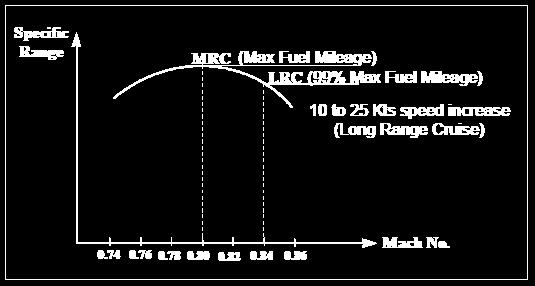
91
 Rate of Climb: Maximum Altitude gain over time (Short")
92 Climb Performance The climb performance of an airplane can be expressed by the two terms: Climb angle: Maximum Altitude gain over distance(short Distance) Rate of Climb: Maximum Altitude gain over time (Short Time)

93 Performance Climb Performance Why is the change from constant IAS to Constant Mach? Climbing at constant IAS will result in the following: The higher the altitude the higher the TAS due to lower air density. The higher the altitude the lower the speed of sound due to lower temperature. At constant IAS the Mach No will increase during climb. Therefore, the climb will continue at a constant IAS, up to those altitudes at which the increased TAS results in reaching the critical Mach number of the wing, at which point the increase of the TAS is ceased by continuing the climb at constant Mach
94 END OF CLIMB PERFORMANCE
95
 Load Factor and Cruise Maneuver capability Fuel Mileage: Endurance: Flying for the longest time (minimum fuel consumption")
96 That portion of the trip which is conducted in level flight between the top of climb (TOC) and the top of descent (TOD) is called the cruise portion of the trip. The factors affecting cruise altitude selection: Fuel Mileage (Range) Load Factor and Cruise Maneuver capability Fuel Mileage: Endurance: Flying for the longest time (minimum fuel consumption expressed by fuel flow or kg/hr) Range: Flying for the longest distance Cruise Performance (maximum Nautical Air Mile per unit of fuel (NAM/1000kg) Specific Range: Distance travelled per unit of fuel)
97 Performance Specific Range Cruise Performance Factors Affecting Specific Range: Altitude Weight speed TAS: True air speed NGM: Nautical Ground Miles GS : Ground Speed
98 Cruise Performance Effect Of Altitude On Specific Range: Fuel consumption remains more or less constant with height because the drag and thrust are constant. However, in practice, fuel consumption in terms of fuel flow (kg/hour), decreases slightly at high altitude, because of the higher propulsive efficiency due to the higher TAS. In other words, the increased TAS at high altitude is the major factor affecting fuel consumption or the fuel mileage to be more accurate. The higher the better, provided you fly at correct weights.

 large overshoots of the optimum altitude should be avoided since the specific range drops off rapidly above and")
99 Optimum Altitude: Cruise Performance The optimum range altitude is the altitude at which the best fuel mileage occurs, and varies little with cruise speed schedule. In other words, for every weight there is an altitude for maximum range. Step Climb: In order to fly at maximum range, an airplane must operate continuously at the optimum altitude. Due to air traffic control constants, a climbing cruise along the optimum altitude is not possible, so that step climbs should be performed around the optimum altitude, within the 1% range loss lines if possible (2000 above and below optimum altitude) large overshoots of the optimum altitude should be avoided since the specific range drops off rapidly above and below optimum altitude.
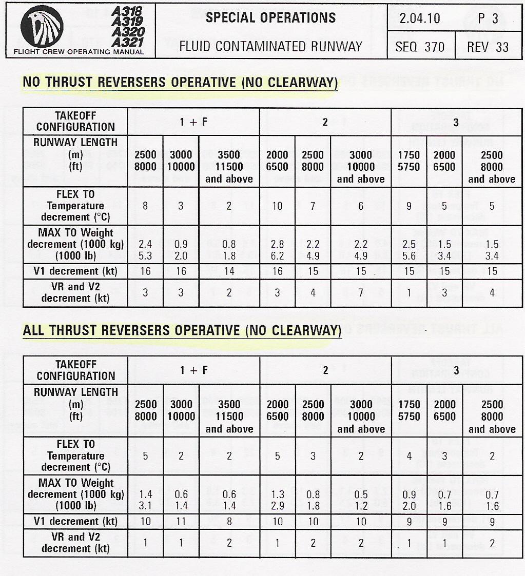
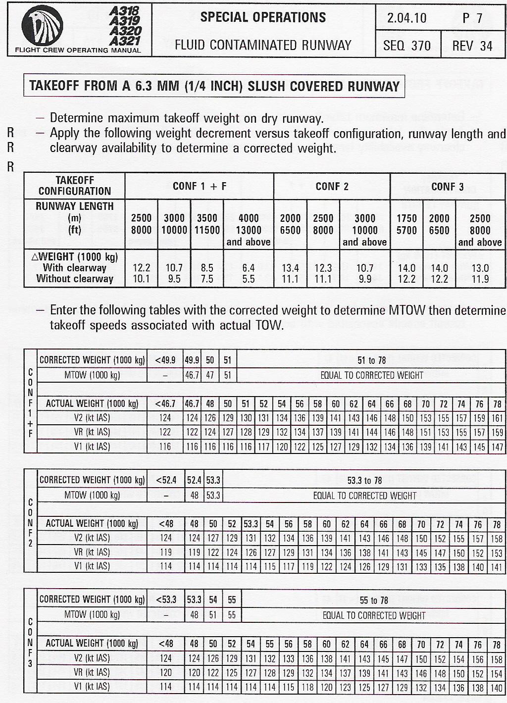
100 Effect Of Speed On Specific Range: Maximum Range Cruise (MRC): For every weight and altitude there is a speed for maximum range. It achieves maximum fuel mileage or maximum range. Maximum range cruise speed will increases with increasing altitude, for a constant weight and Decreases with decreasing weight at constant altitude. Long Range Cruise (LRC): Speed gains a significant increase in speed compared to MRC with only a 1% loss in specific range. Like the MRC speed, the LRC speed also increases with increasing altitude, for a constant weight, and Decreases with decreasing weight at constant altitude. Performance Cruise Performance Effect Of Weight On Specific Range: weight has an effect on fuel mileage due to thrust requirements, in other word, with decreasing in flight weight the specific range increases. In flight weight reduction, has significant effect on improving fuel mileage at high altitude.
101 Cruise Performance
. 3.")
102 Cruise Performance Cruise Maneuver Capability: Load Factor: Load Factor is the ratio between the total air load imposed on the wing in-flight and the gross weight of the airplane. Equivalent weight: The apparent gross weight consists of: 1. Actual weight. 2. The lift force of horizontal stabilizer necessary for aircraft trim (usually downward). 3. Inertial forces of vertical accelerations. 4. Centrifugal forces (TURNS). Buffet Boundaries: Low Speed Buffet High Speed Buffet
103 END OF CRUISE PERFORMANCE
104
105 DAMP RUNWAY CONDITION A runway is damp when the surface is not dry, but when the water on it does not give it a shiny appearance WET A runway is considered as wet when the surface has a shiny appearance due to a thin layer of water. When this layer does not exceed 3 mm depth, there is no substantial risk of hydroplaning
106 RUNWAY CONDITION STANDING WATER It is caused by heavy rainfall and /or insufficient runway drainage with a depth of more than 3 mm SLUSH It is water saturated with snow which spatters when stepping firmly on it. It is encountered at temperatures around 5 C
107 RUNWAY CONDITION WET SNOW It is a condition where, if compacted by hand, snow will stick together and tend to form a snowball DRY SNOW It is a condition where snow can be blown if loose, or if compacted by hand, will fall apart again upon release
108 RUNWAY CONDITION COMPACTED SNOW It is a condition where snow has been compressed (a typical friction coefficient is 0.2) ICY It is a condition where the friction coefficient is 0.05 or below
109 RUNWAY CONDITION The performance given has been divided into two categories which are determined by the depth of the contaminant 1 WET RUNWAY and EQUIVALENT runway covered with or less than 2 mm (0.08 inch) slush 3 mm (0.12 inch) water 4 mm (0.16 inch) wet snow 15 mm (0.59 inch) dry snow
110 Contaminated Runway 12.7 mm (1/2 inch) wet snow is equivalent to 6.3 mm (1/4 inch) slush 25.4 mm (1 inch) wet snow is equivalent to 12.7 mm (1/2 inch) slush 50.8 mm (2 inches) dry snow is equivalent to 6.3 mm (1/4 inch) slush mm (4 inches) dry snow is equivalent to 12.7 mm (1/2 inch) slush Note On a damp runway no performance degradation should be considered It is not recommended to take off from a runway covered with more than 4 inches of dry snow or 1 inch of wet snow
111 Runway Wet or Contaminated Runway Wet Contaminated Water Slush Wet snow Dry snow Comp Snow < 3 mm < 2 mm < 4 mm < 15 mm 3-13 mm (½ ) 2-13 mm (½ ) 4-25 mm (1 ) mm (2 ) all
112 Check that takeoff speeds are greater than the minimum values Performance TAKE-OFF FROM WET RUNWAY Determine the maximum takeoff weight or flexible temperature and associated speeds on dry runway. Two sets of tables are given depending on the use of thrust reversers. Select the table to use as applicable to your case The runway length in the table corresponds to the available takeoff run (TORA) Apply the corrections shown in the table to the maximum takeoff weight or flexible temperature and associated speeds determined on dry runway
113
114 TAKE-OFF FROM WET RUNWAY If one or more speeds are lower than these minimum values, apply the following procedure Actual TOW = maximum TOW If V1 is lower than the minimum V1 (V1 limited by VMCG), take this last value as V1 and further decrease weight Check that VR and V2 are higher than or equal to the minimum values If VR or V2 falls below the minimum values, take-off is not possible Actual TOW lower than maximum TOW, and speeds are lower than minimum value, apply correction
115 Cross wind Reported braking action Reported runway friction coefficient Maximum T/O crosswind (kt) landing Equivalent runway condition ** Good >= * 33 * 1 Good/ Medium Medium 0.39 to to /3 * This is the maximum crosswind demonstrated for dry and wet runway ** Equivalent runway condition (only valid for maximum crosswind determination) 1. Dry, damp or wet runway (less than 3 mm water depth) 2. Runway covered with slush 3. Runway covered with dry snow
116 Performance penalties for take-off are computed with the following assumptions The contaminant is in a layer of uniform depth and density over the entire length of the runway Antiskid and spoilers are operative The screen height at the end of takeoff segment is 15 feet, not 35 feet
117 For contaminated runways only There is drag due to rolling resistance of the wheels There is drag due to spray on the airframe and gears Reverse thrust is used for the deceleration phase Maximum thrust is used for takeoff Note The net flight path clears obstacles by 15 feet instead of 35 feet
118
119 END OF SPECIAL PERFORMANCE
120
121 VREF Speed Reference speed used for normal final approach Equal to 1.23 VS of configuration FULL Displayed on the MCDU APPR page VAPP Speed Final approach speed. Displayed on MCDU APPR page Calculated by the FMGC VAPP = VLS + wind correction + 5 knots The flight crew may modify VAPP through the MCDU VAPP must not be lower than VLS + 5 knots Maximum 15 knots in normal and 20 knots in abnormal
122 Performance LANDING DISTANCE Before Dispatch, The pilot must check that the available runway length at destination is at least equal to the required landing distance for the forecasted landing weight and weather conditions In case of aircraft system failure affecting landing distance known before the dispatch The available runway length must be at least equal to or greater than the required landing distance with failure i.e. The required landing distance without failure multiplied by the coefficient given in the Flight Manual or the MMEL
123 FAILURE IN FLIGHT The concept of required landing distance no longer applies In case of an aircraft system failure occurring in flight and affecting the landing performance, the runway length to be considered for landing is the actual landing distance without failure multiplied by the landing distance coefficient associated with the failure The coefficients are given in FCOM or in the QRH
124 RECOMMENDATIONS For most cases of abnormal landing configuration, the increased actual landing distance does not exceed the required runway length for landing in normal configuration Special notice should be taken of the runway condition A slippery runway is the most common reason for over run at landing The combination of a slippery runway and a factor such as tailwind or an increase in approach speed should avoided As far as possible, avoid the combination of any failure affecting the braking capability of the aircraft such as (spoilers, reversers) with landing on a contaminated runway, or prepare for it carefully by checking the available runway length against the forecasted landing distance
125 MANUAL LANDING LANDING DISTANCE Regulation defines the required landing distance as the actual landing distance divided by 0.6, assuming the surface is dry If the surface is wet, the required landing distance must be at least 115 % of that for a dry surface AUTOMATIC LANDING The required landing distance for automatic landing as the actual landing distance in automatic landing multiplied by This distance must be retained for automatic landing whenever it is greater than the required landing distance in manual mode
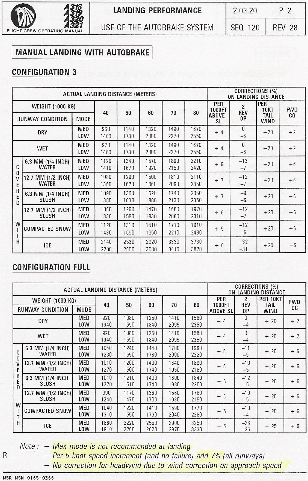
126
127 Approach climb Landing climb Approach flaps Landing gear up Landing flaps Landing gear down One engine inoperative All engine operating T/O thrust on remaining engine Minimum climb gradient 2.1% T/O thrust on both engines Minimum climb gradient 3.2%
128 END OF LANDING PERFORMANCE
129
130 TAXIING PROCEDURES Avoid high thrust settings. When taxiing on slippery surfaces, stay well behind preceding aircraft. Taxi at low speed. Note that antiskid does not operate at low taxi speeds
131 TAXIING PROCEDURES On slippery taxiways during turns with large nose wheel steering angles, noise and vibration may result from the wheels slipping sideways. Keep speed as low as possible to make a smooth turn with minimum radius. Differential power may be needed.
132 TAXIING PROCEDURES If taxiing in icing conditions with precipitation on runways and taxiways contaminated with slush or snow : Before takeoff keep flaps/slats retracted until reaching the holding point on the takeoff runway to avoid contaminating the mechanism.
133 TAXIING PROCEDURES 2. After engine shutdown make a visual inspection to determine that the flap/slat mechanism is free of contamination. 3. When taxiing in after landing, do not retract the flaps/slats to avoid damage of the structure.
134 Note : Performance TAXIING PROCEDURES On contaminated runways and taxiways, the radio altitude indications may fluctuate and auto call outs or GPWS warnings may be activated. Disregard them. During taxi on snowy runways, the radio altimeters may not compute any data and the ECAM warnings
135 TAXIING PROCEDURES ECAM warnings 'DUAL ENG FAILURE', 'ANTI ICE F/O TAT FAULT', 'ANTI ICE CAPT TAT FAULT', 'L/G SHOCK ABSORBER FAULT' may be triggered. Disregard these warnings.
136 TAKE-OFF PROCEDURES For contaminated runways, select MAX TO thrust. Do not abort takeoff for minor deficiencies even at low speeds.
137 TAKE-OFF PROCEDURES If you have to abort takeoff, maintain directional control with the rudder and small inputs to the nose wheel. Do not lift the nose wheel before VR in an attempt to avoid splashing slush on the aircraft, because this produces additional aerodynamic drag.
138 LANDING PROCEDURES The use of auto-brake LOW or MED is recommended. Approach at the normal speed. Make a positive touchdown after a brief flare. As soon as the aircraft has touched down, lower the nose wheel onto the runway and select maximum reverse thrust.
139 LANDING PROCEDURES Do not hold the nose wheel off the ground. If necessary, the maximum reverse thrust can be used until the aircraft is fully stopped. Maintain directional control with the rudder as long as possible, use nose wheel steering with care
140 END OF
Compiled by Matt Zagoren
 The information provided in this document is to be used during simulated flight only and is not intended to be used in real life. Attention VA's - you may post this file on your site for download. Please
FLIGHT PERFORMANCE AND PLANNING (2) PERFORMANCE
 PERFORMANCE") 1 Any acceleration in climb, with a constant power setting, A improves the climb gradient if the airspeed is below VX. B decreases the rate of climb and the angle of climb. C decreases rate of climb and
1 Any acceleration in climb, with a constant power setting, A improves the climb gradient if the airspeed is below VX. B decreases the rate of climb and the angle of climb. C decreases rate of climb and
CESSNA 172-SP PRIVATE & COMMERCIAL COURSE
 CESSNA 172-SP PRIVATE & COMMERCIAL COURSE University of Dubuque INTENTIONALLY LEFT BLANK Revision 1 Standard Operating Procedures 1 CALLOUTS CONDITION Parking Brake Released After Takeoff Power has been
Takeoff Performance. A 1 C change in temperature from ISA will increase or decrease the takeoff ground roll by 10%.
 The precise pilot does not fly by rules of thumb, axioms, or formulas. But there are times when knowledge of an approximate way to calculate things or knowledge of a simple rule can pay big dividends.
NORMAL TAKEOFF AND CLIMB
 NORMAL TAKEOFF AND CLIMB CROSSWIND TAKEOFF AND CLIMB The normal takeoff is one in which the airplane is headed directly into the wind or the wind is very light, and the takeoff surface is firm with no
Engine Performance reciprocating engine, turboprop engine, turbofan engine turbojet engine Manifold pressure (MAP) waste gate critical altitude
 waste gate critical altitude") Engine Performance Note applicable to Chapters 4 and 5: The ATP Single-engine exam (ATS) focuses on the Cessna 208 and the ATP Multi-engine exam (ATM) focuses on the Bombardier CRJ200 and 0400. There are
Engine Performance Note applicable to Chapters 4 and 5: The ATP Single-engine exam (ATS) focuses on the Cessna 208 and the ATP Multi-engine exam (ATM) focuses on the Bombardier CRJ200 and 0400. There are
SUPPLEMENT SEPTEMBER 2010 HIGH ALTITUDE TAKEOFF AND LANDING (ABOVE 14,000 FEET PRESSURE ALTITUDE) MODEL AND ON 68FM-S28-00 S28-1
 MODEL AND ON 68FM-S28-00 S28-1") MODEL 680 680-0001 AND ON HIGH ALTITUDE TAKEOFF AND LANDING (ABOVE 14,000 FEET PRESSURE ALTITUDE) COPYRIGHT 2010 CESSNA AIRCRAFT COMPANY WICHITA, KANSAS, USA 15 SEPTEMBER 2010 S28-1 SECTION V - SUPPLEMENTS
MODEL 680 680-0001 AND ON HIGH ALTITUDE TAKEOFF AND LANDING (ABOVE 14,000 FEET PRESSURE ALTITUDE) COPYRIGHT 2010 CESSNA AIRCRAFT COMPANY WICHITA, KANSAS, USA 15 SEPTEMBER 2010 S28-1 SECTION V - SUPPLEMENTS
CIVIL AIR PATROL United States Air Force Auxiliary Cadet Program Directorate. Cessna 172 Maneuvers and Procedures
 CIVIL AIR PATROL United States Air Force Auxiliary Cadet Program Directorate Cessna 172 Maneuvers and Procedures This study guide is designed for the National Flight Academy Ground School. The information
See the diagrams at the end of this manual for judging position locations.
 Landing Events Penalties General Judges should use airport diagrams, satellite pictures or other means to determine, as accurately as possible, assessments of landing pattern penalties. Judges should be
Airbus Series Vol.2 (c) Wilco Publishing feelthere.com
 Wilco Publishing feelthere.com") Airbus Series Vol.2 (c) Wilco Publishing feelthere.com Frequently Asked Questions Fuel Planning The fuel planner has been improved (since Volume 2 SP1) and is now quite accurate. Nevertheless, you should
Airbus Series Vol.2 (c) Wilco Publishing feelthere.com Frequently Asked Questions Fuel Planning The fuel planner has been improved (since Volume 2 SP1) and is now quite accurate. Nevertheless, you should
Flight Profiles are designed as a guideline. Power settings are recommended and subject to change based
 MANEUVERS AND PROCEDURES Flight Profiles are designed as a guideline. Power settings are recommended and subject to change based upon actual conditions (i.e. aircraft weight, pressure altitude, icing conditions,
AIRCRAFT SYSTEMS AUTO FLIGHT - FLIGHT AUGMENTATION
 Intentionally left blank PRELIMINARY PAGES - TABLE OF CONTENTS DSC-22_40-10 General GENERAL... A DSC-22_40-20 Yaw Functions YAW DAMPING...A RUDDER TRIM...B RUDDER TRAVEL LIMITATION...C DSC-22_40-30 Flight
Aircraft Performance
 Energy Management Aircraft Performance The energy state describes how much of each kind of energy the airplane has available at any given time. Pilots who understand energy management will know instantly
Single Engine Complex Training Supplement PA28R-201 Piper Arrow III (Spring 2016 Revision)
") Single Engine Complex Training Supplement PA28R-201 Piper Arrow III (Spring 2016 Revision) V-speed Quick Reference V-Speed KIAS Description Airspeed Indicator Marking VSO 55 Stall speed in landing configuration
Single Engine Complex Training Supplement PA28R-201 Piper Arrow III (Spring 2016 Revision) V-speed Quick Reference V-Speed KIAS Description Airspeed Indicator Marking VSO 55 Stall speed in landing configuration
Autothrottle Use with Autopilot Off
 Autothrottle Use with Autopilot Off Bill McKenzie Flight Crew Operations Boeing Commercial Airplanes May 2004 757.1 What Is Pitch Coupling The thrust vector for engines mounted under the wing will cause
SULAYMANIYAH INTERNATIONAL AIRPORT MATS
 KURDISTAN REGIONAL GOVERNMENT SULAYMANIYAH INTERNATIONAL AIRPORT MATS APPENDIX " O " SPEED CONTROL GUIDANCE ( First Edition ) April 2012 Prepared By Fakhir.F. Mohammed Civil Aviation Consultant APPENDIX
PROCEDURES GUIDE CESSNA 172N SKYHAWK
 PROCEDURES GUIDE CESSNA 172N SKYHAWK THESE PROCEDURES ARE DESIGNED TO PROVIDE STANDARDIZED METHODS UNDER NORMAL CONDITIONS. AS CONDITIONS CHANGE, THE PROCEDURES WILL NEED TO BE ADJUSTED. PASSENGER BRIEFING
DIRECCION DE PERSONAL AERONAUTICO DPTO. DE INSTRUCCION PREGUNTAS Y OPCIONES POR TEMA
 MT DIREION DE PERSONL ERONUTIO DPTO. DE INSTRUION PREGUNTS Y OPIONES POR TEM 1 TEM: 0292 FLT/DSP - (HP. 03) ERODYNMIS OD_PREG: PREG20084823 (8324) PREGUNT: When are inboard ailerons normally used? Low-speed
ILS APPROACH WITH A320
 1. Introduction ILS APPROACH WITH A320 This document presents an example of an Instrument landing system (ILS) approach performed with an Airbus 320 at LFBO airport runway 32 left. This document does not
Cessna 152 Standardization Manual
 Cessna 152 Standardization Manual This manual is to be utilized in conjunction with the manufacturers approved POH/ AFM and the Airplane Flying Handbook (FAA-H-8083-3A). This manual should be used as a
Aircraft Performance Calculations: Descent Analysis. Dr. Antonio A. Trani Professor
 Aircraft Performance Calculations: Descent Analysis CEE 5614 Analysis of Air Transportation Systems Dr. Antonio A. Trani Professor Aircraft Descent Performance The top of descent point typically starts
Cessna 172S Skyhawk Standardization Manual
 Cessna 172S Skyhawk Standardization Manual This manual is to be utilized in conjunction with the manufacturers approved POH/ AFM and the Airplane Flying Handbook (FAA-H-8083-3A). This manual should be
C-130 Reduction in Directional Stability at Low Dynamic Pressure and High Power Settings
 C-130 Reduction in Directional Stability at Low Dynamic Pressure and High Power Settings The C-130 experiences a marked reduction of directional stability at low dynamic pressures, high power settings,
XI.C. Power-Off Stalls
 References: FAA-H-8083-3; POH/AFM Objectives Key Elements Elements Schedule Equipment IP s Actions SP s Actions Completion Standards The student should develop knowledge of stalls regarding aerodynamics,
Flying The Boeing Advanced
 Flying The Boeing 727-200 Advanced This section includes Pilot s Operating Handbook and Checklists. The POH section is first, followed by the Checklists. FOM: This section includes performance data on
Noise Abatement Takeoff 1 Close In Profile
 PF Duties Captain: Advance thrust to 70% N1 (Allow Engines to stabilize) Noise Abatement Takeoff 1 Close In Profile Flaps Increase Speed to Vref 30 +80kts Climb Checklist Push N1 Button to set Takeoff
LANDING TABLE OF CONTENTS
 LANDING 3-1 LANDING TABLE OF CONTENTS SUBJECT PAGE MINIMUM LANDING RUNWAY LENGTH (737-600)...2 MINIMUM LANDING RUNWAY LENGTH (737-600)...3 MINIMUM LANDING RUNWAY LENGTH (737-700)...4 MINIMUM LANDING RUNWAY
DIRECCION DE PERSONAL AERONAUTICO DPTO. DE INSTRUCCION PREGUNTAS Y OPCIONES POR TEMA
 MT DIREION DE PERSONL ERONUTIO DPTO. DE INSTRUION PREGUNTS Y OPIONES POR TEM 1 TEM: 0114 TP - (HP. 03) ERODYNMIS OD_PREG: PREG20078023 (8358) PREGUNT: What is the safest and most efficient takeoff and
Tecnam Eaglet Standard Operating Procedures and Maneuvers Supplement
 Tecnam Eaglet Standard Operating Procedures and Maneuvers Supplement Normal Takeoff Flaps Take Off Trim set Fuel pump on Check for traffic Line up on white stripe Full power Stick should be located in
Flying The Boeing
 Flying The Boeing 757-200 This section includes Pilot s Operating Handbook and Checklists. The POH section is first, followed by the Checklists. FOM: This section includes performance data on the Boeing
Bonanza/Debonair Pilots
 Bonanza/Debonair Pilots Completing this worksheet is a great way to reinforce the proper speeds for operating your Bonanza or Debonair under varying operating conditions, and to understand the changes
XI.B. Power-On Stalls
 XI.B. Power-On Stalls References: AC 61-67; FAA-H-8083-3; POH/AFM Objectives Key Elements Elements Schedule Equipment IP s Actions SP s Actions Completion Standards The student should develop knowledge
STUDY OF LANDING TECHNIQUE DURING VISUAL APPROACH
 24 TH INTERNATIONAL CONGRESS OF THE AERONAUTICAL SCIENCES STUDY OF LANDING TECHNIQUE DURING VISUAL APPROACH Hiroshi TAKAHARA*, Takashi KONDO*, Shinji SUZUKI** *All Nippon Airways Co., LTD., **University
FALCON SERVICE ADVISORY
 Approach speed considerations Feb 08, 10 Origin: Status: Closed Classification: Operation REASON The aim of this article is to give operational recommendations for computing the approach speed V APP while
SUBPART C - STRUCTURE
 SUBPART C - STRUCTURE GENERAL CS 23.301 Loads (a) Strength requirements are specified in terms of limit loads (the maximum loads to be expected in service) and ultimate loads (limit loads multiplied by
Visualized Flight Maneuvers Handbook
 Visualized Flight Maneuvers Handbook For High Wing Aircraft Third Edition For Instructors and Students Aviation Supplies & Academics, Inc. Newcastle, Washington Visualized Flight Maneuvers Handbook for
NORMAL TAKEOFF PILOT TRAINING MANUAL KING AIR 200 SERIES OF AIRCRAFT
 NORMAL TAKEOFF Climb-Out 1. Accelerate to 160 KIAS 2. Landing/Taxi lights: Out 3. Climb Checklist complete 1. 160 KIAS up to 10,000 ft 2. Decrease 2 KIAS per 1,000 ft above 10,000 ft to 130 KIAS at 25,000
Flying The Embraer Brasilia (EMB-120)
") Flying The Embraer Brasilia (EMB-120) This section includes Pilot s Operating Handbook and Checklists. The POH section is first, followed by the Checklists. FOM: This section includes performance data
Flying The Embraer Brasilia (EMB-120) This section includes Pilot s Operating Handbook and Checklists. The POH section is first, followed by the Checklists. FOM: This section includes performance data
FAA-S-ACS-6 June 2016 Private Pilot Airplane Airman Certification Standards. Task ACS Settings
 FAA-S-ACS-6 June 2016 Private Pilot Airplane Airman Certification Standards Cessna 172: mixture rich, carb heat out if below the green arc. Clearing Turns all manuevers! Task ACS Settings Traffic Pattern
Compiled by Matt Zagoren
 The information provided in this document is to be used during simulated flight only and is not intended to be used in real life. Attention VA's - you may post this file on your site for download. Please
MANEUVERS GUIDE. Liberty Aerospace 1383 General Aviation Drive Melbourne, FL (800)
") MANEUVERS GUIDE Liberty Aerospace 1383 General Aviation Drive Melbourne, FL 32935 (800) 759-5953 www.libertyaircraft.com Normal/Crosswind Takeoff and Climb 1. Complete the runup and before takeoff checklist.
MANEUVERS GUIDE Liberty Aerospace 1383 General Aviation Drive Melbourne, FL 32935 (800) 759-5953 www.libertyaircraft.com Normal/Crosswind Takeoff and Climb 1. Complete the runup and before takeoff checklist.
TECHNIQUES FOR OFF AIRPORT OPERATIONS
 Off Airport Ops Guide TECHNIQUES FOR OFF AIRPORT OPERATIONS Note: This document suggests techniques and procedures to improve the safety of off-airport operations. It assumes that pilots have received
Certification Specifications for Normal, Utility, Aerobatic, and Commuter Category Aeroplanes CS-23
 European Aviation Safety Agency Certification Specifications for Normal, Utility, Aerobatic, and Commuter Category Aeroplanes CS-23 20 July 2012 CS-23 Annex to ED Decision 2012/012/R PREAMBLE CONTENTS
VFR Circuit Tutorial. A Hong Kong-based Virtual Airline. VOHK Training Team Version 2.1 Flight Simulation Use Only 9 July 2017
 A Hong Kong-based Virtual Airline VFR Circuit Tutorial VOHK Training Team Version 2.1 Flight Simulation Use Only 9 July 2017 Copyright 2017 Oasis Hong Kong Virtual Page 1 Oasis Hong Kong Virtual (VOHK)
Piper PA Seminole 1. Standardization Manual
 Piper PA-44-180 Seminole Standardization Manual This manual is to be utilized in conjunction with the manufacturers approved POH/AFM and the Airplane Flying Handbook (FAA-H-8083-3A). This manual should
TAKEOFF & LANDING IN ICING CONDITIONS
 Original idea from Captain A. Wagner T TAKEOFF & LANDING IN ICING CONDITIONS here have been a number of accidents related to take-off in conditions in which snow and/or other forms of freezing precipitation
Civil Air Patrol Auxiliary of the United States Air Force
 Mountain Flying Qualification Course Civil Air Patrol Auxiliary of the United States Air Force Mountain Flying Flying in Mountain Winds Determine direction and velocity of steady winds by observing dust,
Advisory Circular (AC)
") Advisory Circular (AC) Stall, Compliance File No. 5009-6-525 AC No. 525-020 RDIMS No. 528401-V3 Issue No. 01 Issuing Branch Aircraft Certification Effective Date 2004-12-01 1.0 INTRODUCTION... 2 1.1 Purpose...
Advisory Circular (AC) Stall, Compliance File No. 5009-6-525 AC No. 525-020 RDIMS No. 528401-V3 Issue No. 01 Issuing Branch Aircraft Certification Effective Date 2004-12-01 1.0 INTRODUCTION... 2 1.1 Purpose...
767 Flight Crew Training Manual. Maneuvers Chapter 7. Acceleration to and Deceleration from VMO High Altitude Maneuvering, G Buffet... 7.
 7 Maneuvers Table Of Contents Maneuvers Chapter 7 Table of Contents Section TOC Preface................................................. 7.1 Acceleration to and Deceleration from VMO................. 7.1
JAR-23 Normal, Utility, Aerobatic, and Commuter Category Aeroplanes \ Issued 11 March 1994 \ Section 1- Requirements \ Subpart C - Structure \ General
 JAR 23.301 Loads \ JAR 23.301 Loads (a) Strength requirements are specified in terms of limit loads (the maximum loads to be expected in service) and ultimate loads (limit loads multiplied by prescribed
3rd Eurocontrol CDO Workshop
 Airbus Aircraft Energy management in descent phase using FMS Airbus fleet performance Presented by Alexandre Buisson Airbus Operations, Aircraft Performance Specialist Brussels, March 18 th 2013 Table
Cessna Aircraft Short & Soft Field Takeoff & Landing Techniques
 Cessna Aircraft Short & Soft Field Takeoff & Landing Techniques Introduce speaker. 1 Objectives / Content For short- and soft-field takeoff and landing operations in CAP Cessna aircraft, review: Standards
TAILWHEEL AIRPLANES LANDING GEAR TAXIING
 Ch 13.qxd 5/7/04 10:04 AM Page 13-1 TAILWHEEL AIRPLANES Tailwheel airplanes are often referred to as conventional gear airplanes. Due to their design and structure, tailwheel airplanes exhibit operational
Beechcraft Duchess 76 Maneuver Notes
 Beechcraft Duchess 76 Maneuver Notes I. Maneuver notes for Performance (AOA V), Slow Flight and Stalls (AOA VIII), Emergency Operations (AOA X), and Multiengine Operations (AOA XI) a. Maneuvers addressed:
Front Cover Picture Mark Rasmussen - Fotolia.com
 Flight Maneuvers And Stick and Rudder Skills A complete learn to fly handbook by one of aviation s most knowledgeable and experienced flight instructors Front Cover Picture Mark Rasmussen - Fotolia.com
ABS/BPPP Performance Worksheet: Baron/Travel Air Pilots
 ABS/BPPP Performance Worksheet: Baron/Travel Air Pilots This worksheet is the homework for BPPP Initial pilots to complete before their BPPP flight. It s designed to help the pilot develop a deep understanding
Guidance Notes PRIVATE AND COMMERCIAL PILOT TRAINING
 PRIVATE AND COMMERCIAL PILOT TRAINING September 2005 1 st Edition ACKNOWLEDGEMENT Transport Canada thanks the Federal Aviation Administration of the United States for their permission to use the chapter
Sportsman (401) Maneuver Descriptions. And. Suggested Downgrades
 Maneuver Descriptions. And. Suggested Downgrades") Sportsman (401) Maneuver Descriptions And Suggested Downgrades 2015 Purpose: The purpose of this guide is to furnish an accurate description of each maneuver of the Sportsman (401) pattern sequence. Study
Sportsman (401) Maneuver Descriptions And Suggested Downgrades 2015 Purpose: The purpose of this guide is to furnish an accurate description of each maneuver of the Sportsman (401) pattern sequence. Study
VII.E. Normal and Crosswind Approach and Landing
 References: FAA-H-8083-3; POH/AFM Objectives Key Elements Elements Schedule Equipment IP s Actions SP s Actions Completion Standards The student should be able to perform a normal approach and landing
Cessna 172 Profiles. TRAFFIC PATTERNS (Check Chart Supplement prior to flight) Index
 Index") Cessna 172 Profiles TRAFFIC PATTERNS (Check Chart Supplement prior to flight) Index When Cleared for Takeoff - Landing/Taxi lights ON Mixture-As Required Power-Check Takeoff RPM Power Climb at Vy Start
Cessna 172 Profiles TRAFFIC PATTERNS (Check Chart Supplement prior to flight) Index When Cleared for Takeoff - Landing/Taxi lights ON Mixture-As Required Power-Check Takeoff RPM Power Climb at Vy Start
Stalls and Spins. Tom Johnson CFIG
 Stalls and Spins Tom Johnson CFIG Contents Angle of Attack Stall Recognition and Recovery Spin Entry and Recovery Load Limit Considerations Gust Induced Stall and Spin Accidents Stalls a stall is a loss
Stalls and Spins. Tom Johnson CFIG
 Stalls and Spins Tom Johnson CFIG Do we need all of this? Lift The force created by moving the wing through the air. Angle of Attack: The angle between the relative wind and the wing chord line. Stalls
POWER-OFF 180 ACCURACY APPROACH AND LANDING
 POWER-OFF 180 ACCURACY APPROACH AND LANDING OBJECTIVE To teach the commercial student the knowledge of the elements related to a power-off 180 accuracy approach and landing. COMPLETION STANDARDS 1. Considers
Medium, Climbing and Descending Turns
 Basic Concepts Medium, Climbing and Descending Turns A medium turn is defined as a turn using up to 30 degrees angle of bank. Climbing and descending turns are combined with medium turns within this briefing,
CHAPTER 8 MANEUVERS TABLE OF CONTENTS
 CHAPTER 8 MANEUVERS TABLE OF CONTENTS Transition Airspeeds... 3 Checklists and callouts during maneuvers... 3 Guidance to better maneuver execution... 3 Taxiing... 5 Pre-Maneuver Checklist... 6 Clearing
PROCEDURES GUIDE. FLIGHT MANEUVERS for the SPORT PILOT
 Page 1 of 10 PROCEDURES GUIDE FLIGHT MANEUVERS for the SPORT PILOT * Author s Note: Whereas this procedures guide has been written for a specific application, it can easily be modified to fit many different
SCHEMATIC MANEUVER DIAGRAMS. AMA Sportsman
 SCHEMATIC MANEUVER DIAGRAMS AMA Sportsman 401 2015-2017 General Judging Guide The competitor or judge should refer to the AMA Judge s Guide for general information regarding downgrades such as the One
Winter Flying Safety. October, 2015
 Winter Flying Safety October, 2015 Winter Flying: Phases of Flight Preflight (including Wx briefing) Taxi & Takeoff Enroute Approach & Landing Night Currency Due to shorter days, many flights may be completed
Attitude Instrument Flying and Aerodynamics
 Attitude Instrument Flying and Aerodynamics 2.1 TURNS 1. An airplane requires a sideward force to make it turn. a. When the airplane is banked, lift (which acts perpendicular to the wingspan) acts not
Flight Control Systems Introduction
 Flight Control Systems Introduction Dr Slide 1 Flight Control System A Flight Control System (FCS) consists of the flight control surfaces, the respective cockpit controls, connecting linkage, and necessary
Aviation Merit Badge Knowledge Check
 Aviation Merit Badge Knowledge Check Name: Troop: Location: Test Score: Total: Each question is worth 2.5 points. 70% is passing Dan Beard Council Aviation Knowledge Check 1 Question 1: The upward acting
Flight Corridor. The speed-altitude band where flight sustained by aerodynamic forces is technically possible is called the flight corridor.
 Flight Corridor The speed-altitude band where flight sustained by aerodynamic forces is technically possible is called the flight corridor. The subsonic Boeing 747 and supersonic Concorde have flight corridors
NSRCA Club or Novice Class. Maneuver Descriptions. And. Suggested Downgrades
 NSRCA Club or Novice Class Maneuver Descriptions And Suggested Downgrades August 18, 2016 Purpose: The purpose of this guide is to furnish an accurate description of each maneuver of the NSRCA Club or
FFI Formation Guidelines and Standard Procedures Mooney Supplement (28 Dec, 2018; Rev 12)
") FFI Formation Guidelines and Standard Procedures Mooney Supplement (28 Dec, 2018; Rev 12) This document describes formation flight differences between RV and Mooney aircraft. In conjunction with the FFI
FFI Formation Guidelines and Standard Procedures Mooney Supplement (28 Dec, 2018; Rev 12) This document describes formation flight differences between RV and Mooney aircraft. In conjunction with the FFI
Advisory Circular (AC)
") Advisory Circular (AC) Certification of Large Aeroplanes in the Restricted Category, Used for Special Purpose Operations File No. 5009-6-525 AC No. 525-012 RDIMS No. 1140123-V1 Issue No. 02 Issuing Branch
Advisory Circular (AC) Certification of Large Aeroplanes in the Restricted Category, Used for Special Purpose Operations File No. 5009-6-525 AC No. 525-012 RDIMS No. 1140123-V1 Issue No. 02 Issuing Branch
V mca (and the conditions that affect it)
") V mca (and the conditions that affect it) V mca, the minimum airspeed at which an airborne multiengine airplane is controllable with an inoperative engine under a standard set of conditions, is arguably
V mca (and the conditions that affect it) V mca, the minimum airspeed at which an airborne multiengine airplane is controllable with an inoperative engine under a standard set of conditions, is arguably
C-182P MANEUVERS GUIDE TABLE OF CONTENTS
 INTRODUCTION The following maneuver guide is designed to provide a technique for completing each VFR maneuver required by the FAA s Practical Test Standards for the Private Practical Test. By performing
Mountain Fury Mountain Search Flying Course Syllabus
 Mountain Fury Mountain Search Flying Course Syllabus Goals 1. Pilots who complete this program will be able to perform with precision and confidence all of the tasks and flight maneuvers required for safe
PRIVATE PILOT MANEUVERS Practical Test Standards FAA-S A
 PRIVATE PILOT MANEUVERS Practical Test Standards FAA-S-8081-15A Special Emphasis Areas Examiners shall place special emphasis upon areas of aircraft operation considered critical to flight safety. Among
Cessna 172R Profiles
 Cessna 172R Profiles TRAFFIC PATTERNS (Verify pattern altitude) Start your first climbing turn within 300' of pattern altitude Enter 45 degree angle to the downwind leg Depart the traffic pattern straight-out,
Advanced Stalling. L = CL ½ ρ V 2 S. L = angle of attack x airspeed. h L = angle of attack x h airspeed. Advanced Manoeuvres
 Advanced Manoeuvres Advanced Stalling This Advanced Stalling lesson covers the factors that affect the observed airspeed and nose attitude at the stall. Although the aeroplane always stalls when the aerofoil
CRD - NPA 14/ October 2005 Page 1 of 28 (B.) AMC Paragraph / Transport Canada
 AMC Paragraph / Transport Canada") CRD - NPA 14/2004 Comment (B.) AMC 25.1591 Paragraph 2. 20 / Transport Canada Suggest changing paragraph 2, fourth sub paragraph, first sentence to 'with dry snow (depths below 10 mm)' The fourth sub paragraph
CRD - NPA 14/2004 Comment (B.) AMC 25.1591 Paragraph 2. 20 / Transport Canada Suggest changing paragraph 2, fourth sub paragraph, first sentence to 'with dry snow (depths below 10 mm)' The fourth sub paragraph
IVAO International Virtual Aviation Organization Training department
 1 Introduction IVAO International Virtual Aviation Organization Training department TRAFFIC PATTERN DESCRIPTION An aerodrome traffic pattern is used by VFR traffic for training purpose or to prepare the
Performance/Pilot Math
 Performance/Pilot Math Charath Ranganathan, AGI http://pfactor.io/ facebook.com/pfactor.io (chuh-ruh-th) License This work is licensed under a Creative Commons Attribution- NonCommercial-ShareAlike 4.0
Climbs, descents, turns, and stalls These are some of the maneuvers you'll practice, and practice, and practice By David Montoya
 Climbs, descents, turns, and stalls These are some of the maneuvers you'll practice, and practice, and practice By David Montoya Air work stalls, steep turns, climbs, descents, slow flight is the one element
Things to remember when flying N102RE or any Taildragger
 Page 1 of 8 Things to remember when flying N102RE or any Taildragger 1. The Center of Gravity (CG) is behind the main between a taildragger (i.e. conventional gear airplane) and a tricycle gear airplane
Airplane Flying Handbook. Figure 6-4. Rectangular course.
 Airplane Flying Handbook Rectangular Course Figure 6-4. Rectangular course. Normally, the first ground reference maneuver the pilot is introduced to is the rectangular course. [Figure 6-4] The rectangular
TERMS AND DEFINITIONS
 Ch 05.qxd 5/7/04 7:02 AM Page 5-1 GENERAL This chapter discusses takeoffs and departure climbs in tricycle landing gear (nosewheel-type) airplanes under normal conditions, and under conditions which require
Preliminary Study of Aircraft Dynamics and Performance: High Gust Condition Aspect
 Advances in Aerospace Science and Applications. ISSN 2277-3223 Volume 3, Number 2 (2013), pp. 57-62 Research India Publications http://www.ripublication.com/aasa.htm Preliminary Study of Aircraft Dynamics
II.E. Airplane Flight Controls
 References: FAA-H-8083-3; FAA-8083-3-25 Objectives Key Elements Elements Schedule Equipment IP s Actions SP s Actions Completion Standards The student should develop knowledge of the elements related to
FAA AC No. 25-7A Flight Test Guide For Certification Of Transport Category Airplanes S083O(NC)
") FAA AC No. 25-7A Flight Test Guide For Certification Of Transport Category Airplanes S083O(NC) Military fighter, helicopter, business jet, and UAV examples of SpaceAge Control air data products in use.
FAA AC No. 25-7A Flight Test Guide For Certification Of Transport Category Airplanes S083O(NC) Military fighter, helicopter, business jet, and UAV examples of SpaceAge Control air data products in use.
Mountain Fury Mountain Search Flying Course Syllabus Fourth Sortie : High Altitude Search
 Mountain Fury Mountain Search Flying Course Syllabus Fourth Sortie : High Altitude Search Objectives 1. Develop trainee's proficiency in planning and execution of mountain search sorties. 2. Develop trainee's
Civil Air Patrol Auxiliary of the United States Air Force
 Mountain Flying Qualification Course Civil Air Patrol Auxiliary of the United States Air Force DENSITY ALTITUDE Pressure Altitude Pressure Altitude: Absolute altitude corrected for non-standard atmospheric
VII.H. Go-Around/Rejected Landing
 VII.H. Go-Around/Rejected Landing References: FAA-H-8083-3; POH/AFM Objectives Key Elements Elements Schedule Equipment IP s Actions SP s Actions Completion Standards The student should develop knowledge
What is stall? How a pilot should react in front of a stall situation
 The Airbus Safety Magazine Issue 11 JANUARY 2011 5 Jacques ROSAY VP Chief Test Pilot What is stall? How a pilot should react in front of a stall situation 1. Introduction The worldwide air transport fleet
Aircraft Design Prof. A.K Ghosh Department of Aerospace Engineering Indian Institute of Technology, Kanpur
 Aircraft Design Prof. A.K Ghosh Department of Aerospace Engineering Indian Institute of Technology, Kanpur Lecture - 12 Design Considerations: Aerofoil Selection Good morning friends. The last lecture
Gleim Private Pilot Flight Maneuvers Seventh Edition, 1st Printing Updates February 2018
 Page 1 of 11 Gleim Private Pilot Flight Maneuvers Seventh Edition, 1st Printing Updates February 2018 If you are tested on any content not represented in our materials or this update, please share this
Normal T/O Procedure. Short Field T/O Procedure
 Normal T/O Procedure Add full power: Engine Instruments green Airspeed alive 1,000 AGL Accelerate to enroute climb 85 KIAS Complete climb check Vr = 55-60 Vy 79 KIAS Prior to Receiving T/O Clearance Complete
Maximum Rate Turns. Objective To carry out a balanced, maximum rate, level turn using full power.
 Advanced Manoeuvres Maximum Rate Turns To achieve the maximum rate of turn, the greatest possible force toward the centre of the turn is required. This is achieved by inclining the lift vector as far as
Transportation Engineering - II Dr. Rajat Rastogi Department of Civil Engineering Indian Institute of Technology - Roorkee. Lecture - 35 Exit Taxiway
 Transportation Engineering - II Dr. Rajat Rastogi Department of Civil Engineering Indian Institute of Technology - Roorkee Lecture - 35 Exit Taxiway Dear students, we are back with the lecture series of