Production capacity.
|
|
|
- Britton Johnson
- 5 years ago
- Views:
Transcription


1 6400


2 The Company Production, R+D+i, evolution. VALVULAS NACIONAL, S.A. was established in Spain in The main target was to assist the petrochemical and chemical industries emerging in Spain at that time. Right from the start VALVULAS NACIONAL, S.A., has been designing and producing safety valves according to most recognized international standards and norms: API, ASME, ASTM and the European directives 97/23 & 94/9 CE. Our production process is accredited by an ISO certification. Our know how and capacity to adapt to the constantly changing demands of the market, made possible the introduction of new products designed for new applications on the market, like THERMOSOLAR PLANTS, where VALVULAS NACIONAL has supplied safety valves to more than 16 complete plants all over the world, while at the same time continuously supplying to all main players of the Spanish petrochemical, chemical and refining industries. Production capacity. VALVULAS NACIONAL, S.A. valves have their discharge coefficients approved in laboratory tests, in order to guarantee and assure that correct values are being used for every sizing process. In our Technical sales department we count with a modern software which allows us to verify all the possibilities, and to assure strict fulfillment of all international standards. VALVULAS NACIONAL, S.A. has established representation agreements with the most important O.E.M. companies in the safety sector of the industry, consolidating us as one of the main companies by product range; design and consulting in new plants or in new process. Our continuous growth, shows a clear trend, which confirms the integration of our workers to provide first class service to our customers and partners. Factory & location. Our facilities in Rubí (Barcelona - Spain), with more than m2 are fully prepared for our production activities: machining with modern CNC, assembling and testing. We also have long term agreements with approved workshops, which provides us with fleibility and fast feedback to customers demands, with full quality guarantee which has always been our main target. Strategic alliances. Nowadays VALVULAS NACIONAL, S.A. starts an internationalization process, establishing representation agreements in different countries and continents all over the world, with specialized companies that will provide added value in our service towards the end user. VALVULAS NACIONAL providing safety since 1976! 2
3 Inde GENERAL FEATURES 4 NAMEPLATE 5 OPERATION 5 CONSTANT BACK PRESSURE OPERATION 6 VARIABLE BACK PRESSURE OPERATION 6 CODIFICATION SYSTEM 7 PART LIST 8 BILL OF MATERIALS 9 ACCESSORIES 10 GENERAL DIMENSIONS 11 TECHNICAL INFORMATION 12 OPERATING CHARACTERISTICS TABLE 12 CALCULATION FORMULAS FOR ORIFICE AREA 13 CONSTANTS 14 VALUES OF K AND C 15 CORRECTION COEFFICIENTS CHARTS 16 GASES DISCHARGE FLOW 17 STEAM DISCHARGE FLOW 18 LIQUIDS DISCHARGE FLOW 19 CORRECTION FACTORS 20 API SELECTION CHART 21 REACTION FORCES DURING DISCHARGE 28 NOISE DISCHARGE CALCULATION 29 DEFINITIONS (ASME PTC-25) 30 3
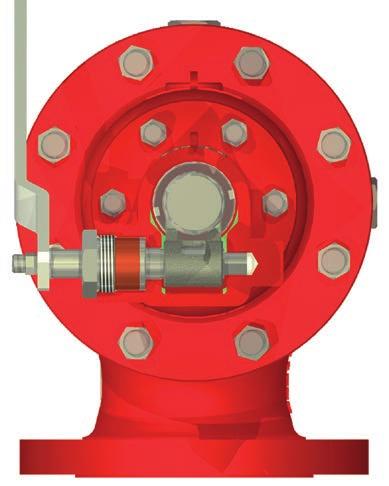
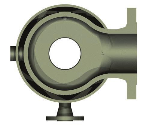
4 General features Model 6400, is an angular type safety valve at 90º between the inlet and the outlet connections, with flanged connections, full nozzle, direct action and spring loaded. Subdivided into three types: Conventional, Balanced (with bellows) and Balanced-Piston. All three are designed with specific trims to work with gases and vapours or liquids. DESIGN Valve body is angular type at 90º between inlet and outlet flanges. Its large internal capacity and smooth section changes help reducing turbulences. Therefore, fluid evacuation on discharge is improved. Full nozzle type, guided and screwed to body, enabling perfect alignment and easy disassembling. Disc is separate from disc-holder, for that reason its repair or change is improved and a better selection of materials can be performed. Stem-push rod design in two parts, enables push rod material to be hardened to withstand high charges, facilitating displacement, avoiding seizure with guide. Guide has a large push rod guide area to prevent premature damage, ensuring perfect alignment with all internals. Bellows are performed so its average area is equal to orifice area thus achieving perfect valve balance and consequently perfect operation before variable back pressures. Its meticulous design enables maimum pressures and temperatures to be supported achieving a high degree of elasticity. Springs are designed with an eperimented highly reliable calculation software and manufactured with the ideal material qualities for the process conditions, ensuring elasticity and accurate repetition of valve opening. For design of the different valve types has taken into account standardisation, enabling a conventional type valve to be converted into balanced with minimum parts change. CODES AND STANDARDS Valves have been designed and manufactured in compliance with the following directives, codes and standards: European Directive: European Directive: Design: Certifications: SIZES AND RATINGS Standard sizes and ratings: 97/23/CE (PED) 94/9/CE (ATEX) EN ISO & ASME VIII DIV-1 PED MODUL B+D / ASME UV & NB Pressure and Temperature Limits: API-526 & ASME Tests: API-527 & ASME Quality system: Materials: ANSI: Sizes: EN ISO-9001:2008 ASTM/ASME & EN 1 2 up to Rating: 150# up to 2500# EN/ISO: Sizes: Rating: DN-25DN-50 up to DN-300DN-400 PN-10 up to PN-250 This catalogue reflects standard valves. Upon request, our technical department can design special applications. The safety valve is an automatic direct action accessory whose function is to relief ecessive overpressures in the recipients and installations that protects. Its main characteristics, allowing is its sudden fluid discharge with complete and fast opening (pop). Automatic valve opening is produced because of the additional push provided by the overpressure of the fluid itself helping to overcome spring resistance. Once the installation has recovered its normal service condition, the valve closes again. Safety valve behaviour is totally different according to whether the fluid it works with on the installation is in gas or liquid phases. To achieve good valve functioning and correct dimensioning, this model was designed with internals for working with gas (Type-64G ) or liquid (Type 64L ). 4

 which is deposited in the")
 creates an additional force contributing to total instantaneous valve opening (Fig.3).")

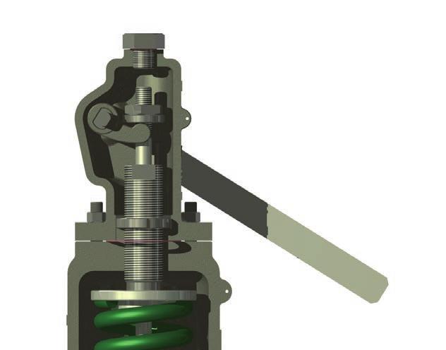
5 NAMEPLATE EN ISO /ASME VIII Div.1 OPERATION The safety valve which protects a pressurized recipient or installation, remains closed until the force eerted by the pressure of fluid P 1, against the disc, is equal to the force of spring F r. (Fig.1). From this point of equilibrium, the disc holder comes away the nozzle, releasing a small amount of fluid, (valve set pressure) which is deposited in the ring chamber (C) formed between the disc holder and adjusting ring (Fig. 2). Chamber pressurization (C) creates an additional force contributing to total instantaneous valve opening (Fig.3). Maimum valve elevation must be achieved without the installation eceeding 10% of overpressure, regardless of whether fluid is in gas or liquid phase. Once cause creating the overpressure has dissapeared, pressure will reduce in the installation to a certain value bellows the set pressure, leaving the valve totally closed. The difference between set pressure and re-seating pressure (blowdown), may be between 7% and 15% depending on whether valve works with gas or liquid. Overpressure and blowdown values may be corrected positioning the adjusting ring more or less distant from the internal disc holder surface. Fr C P1 Fig.1 Fig.2 Fig.3 5
, one must take into account this back pressure value.")

 Type 64 F, correction is not necessary as detailed bellow.")
, a balanced valve (with bellows) Type 64 F must be installed. Bellows function is to eliminate effects caused by back pressure.")
6 OPERATION AT CONSTANT BACK PRESSURE When a conventional safety valve (without bellows) Type 64 C, is installed in a location where fluid discharge is performed on a pressurized collector, with constant pressure ( P 2 ), one must take into account this back pressure value. This back pressure influences on the upper and lower disc holder surface, remaining balanced ecept for the bottom area occupied by the inlet orifice valve ( S a ) where back pressure does not act. This decompensation results in an additional force added to the spring effort. Therefore, at the time of adjusting valve pressure on the test bench, one must subtract from set pressure ( P 1 ), the constant back pressure ( P 2 ). If the valve is balanced (with bellows) Type 64 F, correction is not necessary as detailed bellow. OPERATION AT VARIABLE BACK PRESSURE If conventional valve Type 64 discharges fluid into a collector where back pressure is variable, then the set pressure is affected by the same variation. If this variation is inadmissible (10% greater than set pressure), a balanced valve (with bellows) Type 64 F must be installed. Bellows function is to eliminate effects caused by back pressure. As bellows mean diameter area ( S f ), equals the valve inlet orifice area ( S a ), it isolates the disc holder upper surface from back pressure action, setting it to atmospheric pressure through the vent hole in valve bonnet. As decompensation of areas produced in conventional valves is eliminated, additional efforts on the spring are eliminated. Therefore, when the valve set pressure is adjusted on the test bench, no back pressure correction at all is required. BACK PRESSURE EFFECT When valve initiates opening under back pressure influence due to built-up back pressure or superimposed back pressure, two conditions occur preventing the valve from achieving total elevation without eceeding 10% overpressure: The force on the upper disc holder surface, and pressure reduction on the lower disc holder surface due to disturbances generated on discharging fluid. Back pressure data indicated on the operation technical characteristics table, are eperimental back pressures performed in laboratory on different valve types, and at no time eceeding the maimum overpressure of 10%. COVENTIONAL VALVE BELLOWS VALVE Fr Fr VENT P2 P2 P1 P1 6
7 Codification system 64 G C 2 J A 2 X0 1 st 2 nd 3 rd 4 th 5 th 6 th 7 th 8 th 9 th 10 th 11 th 1 st DIGIT: Valve model 2 nd DIGIT: Work fluid state G: Gas and Vapour L: Liquid 3 rd DIGIT: Valve type C: Conventional F: Bellows P: Bellows-Piston 4 th DIGIT: Inlet nominal size 5 th DIGIT: Orifice size 6 th DIGIT: Outlet nominal size 7 th DIGIT: Inlet rating 1: ASME 150 2: ASME 300 3: ASME 600 4: ASME 900 5: ASME : ASME 2500 A: PN-10 B: PN-16 C: PN-25 D: PN-40 E: PN-63 F: PN-100 G: PN-160 H: PN th DIGIT: Outlet rating (Same 7 th Digit) 9 th DIGIT: Standard quality materials 10 th DIGIT: Material Subclass (Nozzle and Disc) - (see bill of materials) 11 th DIGIT: Standards accesories X0 X1 X2 X3 X4 X5 Y4 Y5 Z2 Z4 W1 W4 W5 V0 Packed Lever Test Gag Packed lever + Test Gag Open Bonnet Open Bonnet + Test Gag Open Bonnet + Test Gag + Packed Lever Plain Lever Plain Lever + Test Gag Bellows Hastelloy C276 + O Ring Inconel X-750 Spring Open bonnet + Packed lever Nozzle with "Stellite" Disc with "Stellite" Magnetic sensor 7


8 Part list COVENTIONAL VALVE BELLOWS VALVE BELLOWS-PISTON VALVE LEVER OPTION
9 Bill of materials CLASS A B C D E N1 (Duple) O (Super Duple) NACE - A ITEM DENOMINATION -29 to 232 ºC 233 to 425 ºC 426 to 538 ºC -45 to 232 ºC -268 to 538 ºC -29 to 260ºC -29 to 316ºC -29 to 425 ºC 1 BODY SA 216 WCB SA 216 WCB SA 217 WC6 SA 352 LCB SA 351 CF8M SA 995 CD4MCuN SA 995 CD3MWCuN SA 216 WCB 2 BONNET SA 216 WCB SA 216 WCB SA 217 WC6 SA 352 LCB SA 351 CF8M SA 995 CD4MCuN SA 995 CD3MWCuN SA 216 WCB 2a OPEN BONNET SA 216 WCB SA 216 WCB SA 216 WCB SA 216 WCB 3 CAP SA 216 WCB (1) SA 216 WCB (1) SA 216 WCB (1) SA 216 WCB (1) SA 351 CF8M (1) SA 351 CF8M (1) SA 351 CF8M (1) SA 216 WCB (1) 4 NOZZLE SEE SUBCLASS 5 DISC 6 GUIDE A 351 CF8M (2) A 351 CF8M (2) A 351 CF8M (2) A 351 CF8M (2) A 351 CF8M (2) A 351 CF8M (2) A 479 S32760 (17) A 351 CF8M (2) 7 ADJUSTING RING A 351 CF8M (3) A 351 CF8M (3) A 351 CF8M (3) A 351 CF8M (3) A 351 CF8M (3) A 351 CF8M (3) A 479 S32760 (17) A 351 CF8M (3) 8 DISC HOLDER A (4) (6) A (4) (6) A (4) (6) A 351 CF8M (2) A 351 CF8M (2) A 351 CF8M (2) A 479 S32760 (17) A 351 CF8M (2) 9 STEM A (5) A (5) A (5) A A A A A SPRING 50CRV4 C.S. H21 T.S. (15) H21 T.S. (15) A A (11) A (11) A (11) INCONEL X ADJUSTING SCREW A (6) A (6) A (6) A A A A A PUSH ROD A (6) A (6) A (6) A (10) A (10) A (10) A (10) A (10) 13 NUT C.S. (7) C.S. (7) C.S. (7) A A A A C.S. (7) 14 LOCK SCREW C.S. (7) C.S. (7) C.S. (7) S.S. S.S. S.S. A 479 S32760 (17) C.S. (7) 15 SPRING BUTTON C.S. (7) C.S. (7) C.S. (7) A A A A C.S. (7) 16 ELASTIC RING 316 S.S. 316 S.S. 316 S.S. 316 S.S. 316 S.S. 316 S.S. 316 S.S. 316 S.S. 17 PLUG C.S. (7) C.S. (7) C.S. (7) S.S. S.S. S.S. A 479 S32760 (17) C.S. (7) 18 ELASTIC PIN 302 S.S. 302 S.S. 302 S.S. 302 S.S. 302 S.S. 302 S.S. 302 S.S. 302 S.S. 19 NUT 316 S.S. 316 S.S. 316 S.S. 316 S.S. 316 S.S. 316 S.S. A 479 S32760 (17) 316 S.S. 20 LOCK STUD 316 S.S. 316 S.S. 316 S.S. 316 S.S. 316 S.S. 316 S.S. 316 S.S. 316 S.S. 21 GASKET Compressed Fibers Graphite+316 S.S. (9) Compressed Fibers (12) 22 PLUG C.S. (7) C.S. (7) C.S. (7) S.S. S.S. S.S. S.S. C.S. (7) 23 STUDS SA 193 B7 (7) SA 193 B7 (7) SA 193 B16 (7)(17) SA 193 B8 (7) SA 193 B8 (7) SA 193 B8 (7) SA 193 B8 SA 193 B7 (7) 24 NUTS SA 194 2H (7) SA 194 2H (7) SA (7)(17) SA 194 G8 (7) SA 194 G8 (7) SA 194 G8 (7) SA 194 G8 SA 194 2H (7) 26 GASKET Compressed Fibers Graphite+316 INOX. (9) Compressed Fibers (12) 27 GASKET Compressed Fibers Graphite+316 INOX. (9) Compressed Fibers (12) 28 GASKET Compressed Fibers Graphite+316 INOX. (9) Compressed Fibers (12) 29 GASKET Compressed Fibers Graphite+316 INOX. (9) Compressed Fibers (12) 33 BELLOWS 316Ti S.S. (8) 316Ti S.S. (8) 316Ti S.S. (8) (14) 316Ti S.S. (8) 316Ti S.S. (8) (14) 316Ti S.S. (8) (14) 316Ti S.S. (8) INCONEL GASKET Compressed Fibers Graphite+316 INOX. (9) Compressed Fibers (12) 37 CAM 316 S.S. 316 S.S. 316 S.S. 316 S.S. 316 S.S. 316 S.S. 316 S.S. 316 S.S. 38 BRACKET C.S. (7) C.S. (7) C.S. (7) C.S. (7) 316 S.S. 316 S.S. 316 S.S. C.S. (7) 39 LEVER CAP SA 216 WCB SA 216 WCB SA 216 WCB SA 216 WCB SA 351 CF8M SA 351 CF8M SA 351 CF8M SA 216 WCB 40 LEVER STEM A (5) A (5) A (5) A A A A A LEVER C.S. (7) C.S. (7) C.S. (7) C.S. (7) C.S. (7) C.S. (7) C.S. (7) C.S. (7) 42 PACKING Compressed Fibers Braid Graphite Compressed Fibers (12) 43 LEVER SHAFT A A A A A A A A NUT C.S. (7) C.S. (7) C.S. (7) C.S. (7) C.S. (7) C.S. (7) C.S. (7) C.S. (7) 45 PACKING GLAND C.S. (7) C.S. (7) C.S. (7) C.S. (7) S.S. S.S. S.S. S.S. 46 PISTON A (6) A (6) A (6) A (6) A (6) A (6) A A (6) 47 LOCK WASHER 304 S.S. 304 S.S. 304 S.S. 304 S.S. 304 S.S. 304 S.S. 304 S.S. 304 S.S. 53 NUT C.S. (7) C.S. (7) C.S. (7) C.S. (7) S.S. S.S. S.S. S.S. SUBCLASS (Duple) 11 (Super Duple) 4 NOZZLE SA (13) SA ST. (13) SA ST. (13) SA (13) SA 479 S32550 (13) SA 479 S32760 (13) 5 DISC SA SA (10) SA ST. SA (10) SA 479 S32550 SA 479 S32760 (1) Models with inlet size 1 and 1 1/2, made of Carbon Steel or Stainless Steel bar (2) Models with inlet size 1 and 1 1/2, made of equivalent bar material (3) Orifices D-E-F, made of equivalent bar material (4) For Gas, orifices from M to T, made of equivalent casting material. For Liquid, orifices from P to T, made of equivalent casting material (5) Quenched and Tempered to HRc, if necessary. Models with inlet size 1 and 1 1/2, Stem made of A (6) Quenched and Tempered to HRc (7) Electrolytic bath, Zincate (8) Bellows endings made of 316L S.S. (9) Graphite gasket with 316 S.S. reinforcement (10) H900 Condition, hardness must be between HRc. For temperatures > -30ºC. H1150-M Condition, hardness must be between HRc. For temperatures < -30ºC. (11) PaFor temperatures > 300ºC, material Inconel X-750 (Tempered) (12) For temperatures > 232ºC and <-29ºC, material Graphite with 316 S.S. reinforcement (13) Models with inlet size from 3 to 8, made of equivalent casting material (14) For temperatures > 450ºC, material Inconel 625 (15) When the spring is unenclosed, carbon or alloy steel is used 9


10 Accessories TEST-GAG LEVER O-RING MAGNETIC SENSOR HEATING JACKET 10


11 D A F C E D A C E General Dimensions "Orifice API 526 D E F G H J K L M N P Q R T V W Rating Inlet Outlet Flow Area General Dimensions Standard Lever (cm 2 ) A B C D E F Weight - (Kg) L 150 1" 2" , ½" 2" ½" 3" L 150 1" 2" , ½" 2" ½" 3" L 150 1½" 2" , ½" 3" L ½" 3" , " 3" L 150 1½" 3" , " 3" L " 3" 9,07 3" 4" B L " " 13, " L 150 3" 4" , " 6" L " 6" L " 6" 32, L " 6" 46, L " 8" 78, " 8" L " 10" L " 10" " 14" " 16" B 11
12 Technical information / Operating technical characteristics table DISCHARGE COEFFICIENT (at 10% of overpressure) BLOWDOWN SAFETY VALVE MODEL GC 64GF 64GP 64LC 64LF 64LP conventional bellows conventional bellows SERVICE GAS LIQUID (1)(2) Kd 0,97 0,80 MAX. MIN. -7% (4) -2% -20% (5) -12% SUPERIMPOSED BACKPRESSURE (3) MAX. 10% 25% 10% 40% BUILT-UP BACKPRESSURE (3) MAX. 15% 40% 15% 50% SET PRESSURE TOLERANCE (6) ± 3% MINIMUM SET PRESSURE ASME VIII (bar) EN ISO (bar) 1 0,5 (1) or 0,1 bar, whichever is greater (2) Certificate test in the National Board Testing Lab. (3) Maimum allowable backpressure without overpressure eceeds 10% (4) or 0,2 bar, whichever is greater (5) or 0,6 bar, whichever is greater (6) or ± 0,15 bar, whichever is greater OPERATING VALVE GRAPHIC ON TEST BENCH WITH WATER: MODEL: 64LF SIZE: 2 3 ORIFICE: J SET PRESSURE: 5,6 bar Blowdown Overpressure Discharge coefficient (Kd) Total lift Clossing Pressure Pop action Set pressure 12
13 Technical Information Calculation Formulas for the Orifice Area The following formulas determine the minimum area the safety valve should have to discharge the fluid flow requested Liquids Gases and Vapours Steam Discharge coefficient (K) for safety valves model 6400 Gases and Vapours Liquids K=0,97 K=0,80 Definition of calculation terms Orifice area Discharge flow Discharge pressure (set pressure + overpressure ) Set pressure Back pressure Back pressure abs. Over pressure Relieving temperature Compressibility factor at P and T (use 1 if unknow) Molecular weight Epansion coefficient as function of (k) Specific heats rartio (use k=1,001 if unknow) Vapour specific volume ar T and T Liquid specific gravity at P and T Liquid vapour pressure at P and T Critical pressure Discharge coefficient Correction coefficient by back pressure for conventional valves if P b >0,5P (gases and vapours) Correction coefficient by back pressure for balanced valves if P 2 >0,3P 1 (gases and vapours) Correction coefficient by back pressure for balanced valves if P 2 >0,15P 1 (liquids) Correction coefficient for viscous liquids Correction coefficient due to overpressure different to 25% A (cm 2 ) W (kg/h) P (kg/cm 2 ) (a) P1 (kg/cm 2 ) P2 (kg/cm 2 ) Pb (kg/cm 2 ) S (%) T (ºK) Z M C k (cp/cv) V 1 (m 3 /kg) E (kg/dm 3 ) P v (kg/cm 2 ) (a) P c K 1 K 2 K 3 K v K p 13
14 Technical information / Constants Constants of some fluids to be used on calculation formulas Specific Gravity Critical Point Fluids M k = cp / cv (1) Gas Liquid Pressure Temp. Sp. Grav. Kg/Nm 3 Kg/dm 3 Kg/cm 2 ºC Kg/dm 3 Acetylene 26,04 1,26 1,171 0,613 64,7 35,7 0,231 Acetic Acid 60,05 1,15 2,681 1, ,6 0,351 Hydrochloric Acid 36,47 1,41 1, ,4 0,61 Nitric Acid 1,502 Sulfuric Acid 1,834 Air 28,96 1,41 1,293 0,875 38,4-140,7 0,31 Ethyl Alcohol 46,07 1,13 2,057 0,789 65, ,28 Methyl Alcohol 32 1,2 1,429 0, , ,358 Ammonia 17,03 1,31 0,771 0,68 115,2 132,4 0,235 Sulfhur Dioide 64,06 1,29 2,922 1,434 80,4 157,3 0,524 Argon 39,94 1,67 1,784 1,404 49,6-122,4 0,531 Venzene 78,11 1,12 3,487 0,879 49,6 288,6 0,305 Butane - n 58,12 1,09 2,703 0,6 37,2 153,2 Butane - iso 58,12 1,1 2,668 0,595 37,7 133,7 Chlorine 70,91 1,35 3,22 1,558 78, ,573 Carbon Dioide 44,01 1,3 1,977 1, ,46 Dowtherm - A 165 1,05 7,365 0,997 Ethane 30,07 1,19 1,356 0,546 50,6 35 0,21 Ethylene 28,05 1,24 1,261 0,568 52,4 9,5 0,216 Freon ,92 1,14 5,397 1,486 Freon ,48 1,18 3,86 1,419 Fuel Oil 0,899 Natural Gas 19 1,27 0,853 Gasoline 0,75 Helium 4 1,66 0,179 0,125 2,33-267,9 0,069 Heptane - n 100,2 1,05 4,473 27,8 266,8 0,234 Heane - n 86,17 1,06 3,847 0,659 30,8 234,8 0,234 Hydrogen 2,02 1,41 0,09 0,071 13,2-239,9 0,031 Kerosene 0,815 Metane 16,04 1,31 0,717 0,415 47,2-82,5 0,162 Nitrogen 28,02 1,4 1,251 0,81 34,6-147,1 0,311 Octane - n 114,22 1,05 5,099 0,707 25,5 296,2 0,233 Nitrous Oide 44,02 1,3 1,978 1, ,5 0,46 Oygen 32 1,4 1,429 1,131 51,4-118,8 0,43 Pentane - n 72,15 1,07 3,221 0,631 34, ,232 Propane 44,09 1,13 2,019 0,585 43,3 96,8 0,226 Carbon Disulphide 76,13 1,21 3,398 1,263 77, ,441 (1) Values of k at 15ºC and º Atm. 14
15 Technical information / Values of K y and C Values of k=cp/cv for Steam P 1 bar abs T1 ºC (ºK) (473,15) 1,31 1,31 1,31 1,30 1, (523,15) 1,31 1,31 1,30 1,30 1,29 1, (573,15) 1,30 1,30 1,30 1,29 1,29 1,29 1,29 1,28 1,27 1,27 1,26 1, (623,15) 1,30 1,30 1,29 1,29 1,29 1,29 1,29 1,28 1,28 1,28 1,27 1, (673,15) 1,29 1,29 1,29 1,29 1,29 1,29 1,28 1,28 1,28 1,28 1,28 1, (723,15) 1,28 1,28 1,28 1,28 1,28 1,28 1,28 1,28 1,28 1,28 1,28 1, (773,15) 1,28 1,28 1,28 1,28 1,28 1,28 1,28 1,28 1,28 1,28 1,28 1, (823,15) 1,27 1,27 1,27 1,27 1,27 1,27 1,27 1,27 1,27 1,27 1,28 1, (873,15) 1,27 1,27 1,27 1,27 1,27 1,27 1,27 1,27 1,27 1,27 1,27 1, (923,15) 1,26 1,26 1,26 1,26 1,26 1,26 1,26 1,26 1,26 1,26 1,27 1, (973,15) 1,26 1,26 1,26 1,26 1,26 1,26 1,26 1,26 1,26 1,26 1,26 1,26 Saturated Steam P 1 bar abs T1 ºC 99,63 133,54 151,85 179,88 198,28 212,37 233,84 250,33 263,92 275,56 285,8 294,98 ºK 372,78 406, ,03 471,43 485,52 506,99 523,48 537,07 548,71 558,95 568,13 k = cp/cv 1,32 1,31 1,31 1,3 1,29 1,29 1,28 1,27 1,27 1,26 1,26 1,25 T1 ºC (ºK) (473,15) 250 (523,15) 300 (573,15) 350 (623,15) 1,27 1,26 1,25 1,25 1, (673,15) 1,28 1,28 1,28 1,28 1,28 1,28 1,28 1,30 1,31 1,32 1,33 1, (723,15) 1,28 1,28 1,29 1,29 1,29 1,29 1,30 1,31 1,32 1,34 1,36 1, (773,15) 1,28 1,28 1,29 1,29 1,30 1,30 1,31 1,32 1,33 1,34 1,35 1, (823,15) 1,28 1,28 1,28 1,29 1,29 1,29 1,30 1,31 1,31 1,32 1,33 1, (873,15) 1,27 1,27 1,28 1,28 1,29 1,29 1,30 1,30 1,31 1,32 1,32 1, (923,15) 1,27 1,27 1,27 1,28 1,28 1,28 1,29 1,29 1,30 1,30 1,30 1, (973,15) 1,26 1,26 1,27 1,27 1,27 1,27 1,28 1,29 1,29 1,29 1,30 1,30 Saturated Steam T1 ºC 303,31 310,96 324,64 336,63 347,32 356,96 365,71 373,68 ºK 576,46 584,11 597,79 609,78 620,47 630,11 638,86 646,83 k = cp/cv 1,25 1,25 1,24 1,24 1,24 1,25 1,27 1,3 Values of C as function of k k C k C k C k C 0,40 0,417 1,01 0,609 1,40 0,685 1,82 0,747 0,45 0,439 1,02 0,611 1,42 0,688 1,84 0,750 0,50 0,459 1,04 0,615 1,44 0,691 1,86 0,752 0,55 0,478 1,06 0,620 1,46 0,695 1,88 0,755 0,60 0,496 1,08 0,624 1,48 0,698 1,90 0,758 0,65 0,512 1,10 0,628 1,50 0,701 1,92 0,760 0,70 0,528 1,12 0,633 1,52 0,704 1,94 0,763 0,75 0,543 1,14 0,637 1,54 0,707 1,96 0,765 0,80 0,557 1,16 0,641 1,56 0,710 1,98 0,767 0,82 0,562 1,18 0,645 1,58 0,713 2,00 0,770 0,84 0,567 1,20 0,649 1,60 0,716 2,10 0,781 0,86 0,573 1,22 0,652 1,62 0,719 2,20 0,793 0,88 0,578 1,24 0,656 1,64 0,722 2,30 0,803 0,90 0,583 1,26 0,660 1,66 0,725 2,40 0,813 0,92 0,588 1,28 0,664 1,68 0,728 2,50 0,823 0,94 0,593 1,30 0,667 1,70 0,731 2,60 0,832 0,96 0,597 1,32 0,671 1,72 0,734 2,70 0,841 0,98 0,602 1,34 0,674 1,74 0,736 2,80 0,850 0,99 0,604 1,36 0,678 1,78 0,742 2,90 0,858 1,001 0,607 1,38 0,681 1,8 0,745 3,00 0,866 15
16 Technical information / Correction coefficient charts Correction Coefficients rc, K 1, K 2, K 3, K p Correction Coefficient by back pressure for conventional valves K 1 (Gases and Vapours) Critical pressure coefficient rc (Water) Coefficient K 1 1'10 1'00 0'90 0'80 0'70 0'60 0'50 0'40 0'30 0'20 0'10 Coefficient rc 1'0 0'9 0'8 0'7 0' ( Pb / P ) Pv Correction Coefficient by back pressure for balanced valves K 2 (Gases and Vapours) Critical pressure coefficient rc (Liquids) 1'10 Coefficient K 2 1'00 0'90 0'80 0'70 0'60 0'50 0'40 0'30 Overpressure 20% Overpressure 10% Coefficient rc 1'00 0'90 0'80 0'70 0'20 0'10 0' ( P 2 / P 1 ) ( Pv / Pc ) 100 Correction Coefficient by back pressure for balanced valves K 3 (Liquids) Kv Viscosity Correction Factor 1' '00 0' Coefficient K 3 0'80 0'70 0'60 0'50 0'40 0'30 Overpressure 25% Overpressure 10% '20 0' ( P 2 / P 1 ) R e = Reynold s Number 16
17 Technical information Gases discharge flow / Capacity chart - Air Values used in the formulas Flow Nm³/h Compressibility factor Z: 1 Temperature: 15º C Overpressure 10% (*) Specific Heat Ratio K: 1,41 Discharge coefficient derated: 0,970 P 1 D E F G H J K L M N P Q R T Kg/cm² 0,78 1,43 2,27 3,63 5,72 9,07 13,2 20, ,2 46,6 78, , , , , , , , , , , , , , , , , , , , , , , , , , , , , , , , , , , , , , , , , , , , , , , , , , , , , , , , , , , (*) Minimum soverpressure 0,2 bar g It is recommended, if possible, selecting the orifice by applying the calculation formulas. These tables can be useful when a quick estimatation of the orifice is required. Atmospheric pressure will be considered 17
18 Technical information Steam discharge flow / Capacity chart - steam Flow: Kg/h Overpressure: 10% Discharge coefficient derated: 0,873 The results shown correspond to calculations for saturated steam For superheated steam, multiply by Ks Minimum overrpessure 0,2 bar g P 1 D E F G H J K L M N P Q R T Kg/cm 2 0,78 1,43 2,27 3,63 5,72 9,07 13,2 20, ,2 46,6 78, , , , , , (*)It is recommended, if possible, selecting the orifice by applying the calculation formulas. These tables can be useful when a quick estimatation of the orifice is required. Atmospheric pressure will be considered 18
19 Technical information Liquids discharge flow / Capacity chart - liquids Flow: m³/h The results shown correspond to calculations for water Overpressure: 10% For different relative densities of water to 1, multiply by Kg Discharge coefficient derated: 0,800 Minimum overpressure 0,2 bar g P 1 D E F G H J K L M N P Q R T Kg/cm 2 0,78 1,43 2,27 3,63 5,72 9,07 13,2 20, ,2 46,6 78, ,5 2,37 4,34 6,89 11,03 17,37 27,55 40,09 61,96 78,97 97,80 141,54 238,43 343,21 558,86 1 3,10 5,69 9,03 14,44 22,75 36,07 52,49 81,13 103,39 128,05 185,32 312,17 449,37 731,72 1,5 3,69 6,77 10,74 17,18 27,07 42,93 62,48 96,56 123,06 152,41 220,57 371,56 534,86 870,92 2 4,20 7,70 12,22 19,55 30,80 48,84 71,08 109,84 140,00 173,38 250,92 422,68 608,45 990,75 2,5 4,70 8,61 13,67 21,85 34,43 54,60 79,46 122,81 156,52 193,85 280,54 472,58 680, ,69 3 5,14 9,43 14,97 23,94 37,72 59,81 87,05 134,53 171,46 212,35 307,31 517,68 745, ,42 3,5 5,56 10,19 16,17 25,86 40,74 64,61 94,02 145,31 185,20 229,36 331,93 559,16 804, ,64 4 5,94 10,89 17,29 27,64 43,56 69,07 100,52 155,34 197,99 245,20 354,85 597,77 860, ,13 4,5 6,30 11,55 18,33 29,32 46,20 73,26 106,61 164,77 210,00 260,07 376,38 634,03 912, ,13 5 6,64 12,17 19,33 30,90 48,70 77,22 112,38 173,68 221,36 274,14 396,74 668,32 962, ,51 6 7,27 13,34 21,17 33,85 53,35 84,59 123,11 190,26 242,48 300,31 434,60 732, , ,03 7 7,86 14,41 22,87 36,57 57,62 91,37 132,97 205,50 261,91 324,37 469,43 790, , ,53 8 8,40 15,40 24,45 39,09 61,60 97,68 142,15 219,69 279,99 346,76 501,84 845, , ,50 9 8,91 16,33 25,93 41,46 65,34 103,60 150,77 233,01 296,98 367,80 532,28 896, , , ,39 17,22 27,33 43,71 68,87 109,20 158,93 245,62 313,04 387,69 561,07 945, , , ,85 18,06 28,67 45,84 72,23 114,53 166,69 257,61 328,32 406,62 588,46 991, , , ,29 18,86 29,94 47,88 75,44 119,63 174,10 269,06 342,92 424,70 614, , , , ,71 19,63 31,16 49,83 78,52 124,51 181,21 280,05 356,92 442,04 639, , , , ,11 20,37 32,34 51,71 81,49 129,21 188,05 290,62 370,40 458,72 663, , , , ,50 21,09 33,47 53,53 84,35 133,75 194,65 300,82 383,40 474,82 687, , , , ,88 21,78 34,57 55,28 87,11 138,13 201,03 310,69 395,97 490,40 709, , , , ,24 22,45 35,64 56,99 89,80 142,38 207,22 320,25 408,16 505,49 731, , , , ,60 23,10 36,67 58,64 92,40 146,51 213,23 329,53 419,99 520,14 752, , , , ,95 23,73 37,67 60,24 94,93 150,53 219,07 338,56 431,50 534,40 773, , , ,28 24,35 38,65 61,81 97,40 154,44 224,76 347,36 442,71 548,28 793, , , ,85 27,22 43,21 69,10 108,89 172,67 251,29 388,36 494,97 613,00 887, , , ,27 29,82 47,34 75,70 119,29 189,15 275,27 425,42 542,21 671,50 971, , ,57 32,21 51,13 81,77 128,84 204,30 297,33 459,51 585,65 725, , , ,78 34,43 54,66 87,41 137,74 218,41 317,86 491,24 626,09 775, , , ,92 36,52 57,98 92,71 146,09 231,66 337,14 521,04 664,07 822, , , ,00 38,50 61,11 97,73 154,00 244,19 355,38 549,22 699,99 866, , ,02 40,38 64,10 102,50 161,51 256,11 372,72 576,03 734,15 909, , ,00 42,17 66,95 107,06 168,70 267,49 389,30 601,64 766,80 949, , ,94 43,90 69,68 111,43 175,58 278,42 405,19 626,21 798,11 988, , ,85 45,55 72,31 115,63 182,21 288,93 420,49 649,85 828, , , ,72 47,15 74,85 119,69 188,61 299,07 435,25 672,66 857, , , ,56 48,70 77,30 123,62 194,79 308,88 449,52 694,72 885, , ,38 50,20 79,68 127,42 200,79 318,38 463,36 716,10 912, , ,17 51,65 81,99 131,12 206,61 327,61 476,79 736,86 939, , ,95 53,07 84,24 134,71 212,27 336,59 489,85 757,05 964, ,70 54,45 86,43 138,21 217,78 345,33 502,58 776,72 989, ,15 57,10 90,65 144,96 228,41 362,19 527,11 814, , ,53 59,64 94,68 151,40 238,57 378,29 550, ,86 62,08 98,54 157,58 248,31 393,74 573, ,14 64,42 102,26 163,53 257,69 408,60 594, ,37 66,68 105,85 169,27 266,73 422,95 615, ,57 68,87 109,32 174,82 275,48 436,82 635, ,72 70,99 112,69 180,20 283,96 450,26 655, ,84 73,05 115,96 185,43 292,19 463,31 674, ,94 75,05 119,13 190,51 300,20 476, ,00 77,00 122,23 195,46 307,99 488, ,05 80,76 128,19 205,00 323,03 512, ,01 84,35 133,89 214, ,89 87,79 139,36 222, ,69 91,11 144,62 231, ,44 94,30 149, ,13 97,40 154, ,76 100,39 159,37 Correction coeff. Spec. Grvty. D Kg 0,20 2,240 0,30 1,825 0,40 1,580 0,50 1,414 0,60 1,320 0,70 1,195 0,80 1,117 0,84 1,091 0,88 1,066 0,92 1,043 0,96 1,021 1,00 1,000 1,04 0,981 1,08 0,962 1,12 0,945 1,16 0,928 1,20 0,913 1,30 0,877 19
20 Technical information / Correction factors DENS. Kg º C Kt K Kc P 1 (Kg/cm 2 ) T (º C) 0,99 0,97 0,93 0,89 0,85 0,81 0,77 Superheated steam (º C) Ks 0,20 2, ,087 1,01 1,000 0, ,5 417,5 493,5 0,30 1, ,075 1,02 1, , , ,40 1, ,063 1,04 1,016 1, ,50 1, ,052 1,06 1, , ,5 491,8 0,60 1, ,041 1,08 1,029 2, ,5 413,5 491,5 0,70 1, ,030 1,10 1, ,5 348, ,80 1, ,020 1,12 1,044 3, , ,82 1, ,010 1,14 1, ,5 346, ,8 0,84 1, ,000 1,16 1,057 4,5 154, ,5 0,86 1, ,9905 1,18 1, , ,5 0,88 1, ,9813 1,20 1, ,5 409,5 490,2 0,90 1, ,9723 1,22 1, , , ,92 1, ,9636 1,24 1, , ,5 0,94 1, ,9552 1,26 1, ,5 407, ,96 1, ,9469 1,28 1, ,5 345, ,98 1, ,9388 1,30 1, , ,00 1, ,9310 1,32 1, , , ,5 1,02 0, ,9233 1,34 1, , ,04 0, ,9158 1,36 1, , , , ,06 0, ,9014 1,38 1, , , ,08 0, ,8876 1,40 1, , ,5 304, ,10 0, ,8746 1,42 1, ,8 1,12 0, ,8619 1,44 1, , ,8 1,14 0, ,8498 1,46 1, , , ,5 406,5 487,8 1,16 0, ,8383 1,48 1, ,5 310, ,7 487,8 1,18 0, ,8272 1,50 1, ,20 0, ,8165 1,52 1, , , ,25 0, ,8062 1,54 1, ,30 0, ,7963 1,56 1, , ,35 0, ,7868 1,58 1, , ,40 0, ,7776 1,60 1, ,45 0, ,7360 1,62 1, ,50 0, ,7005 1,64 1, ,55 0, ,6695 1,66 1, ,60 0, ,6425 1,68 1, ,65 0, ,6183 1,70 1,207 1,70 0, ,5968 2,00 1,270 1,75 0,756 2,20 1,308 1,80 0,745 1,90 0,725 2,00 0,707 2,10 0,690 2,20 0,674 2,30 0,659 2,40 0,645 2,50 0,633 NOTE: In case of using the flow charts on the previous pages for orifice determination, it will be necessary to apply the corrector factors here indicated for fluids or other working conditions different than those for which it has been calculated the mentioned charts. 20
21 Technical information / API selection chart Materials Carbon Steel Cr-Mo. Steel Body Carbon Steel Tungsten Steel Spring Inlet Temperature ºF Set pressure Kg/cm Selection Chart ASME B API / /0 11/ /2-900 Area Orifice 0 78 cm 2 D 11/ /0 11/0 11/ / Inlet Temperature ºC Set pressure PSIG Materials Selection Chart ASME B API 526 Area Orifice 1 43 cm 2 E Carbon Steel Cr-Mo. Steel Body Carbon Steel Tungsten Steel Spring Inlet Temperature ºF Set pressure Kg/cm / /0 11/ / / /0 11/0 11/ / Set pressure PSIG Inlet Temperature ºC 21
22 Technical information / API selection chart Materials Carbon Steel Cr-Mo. Steel Body Carbon Steel Tungsten Steel Spring Inlet Temperature ºF Set pressure Kg/cm / 11/ 11/ 11/ Selection Chart ASME B API / / 11/ / / /0 11/2-900 Area Orifice 2 27 cm 2 F 11/ / /0 11/0 11/ / / Set pressure PSIG Inlet Temperature ºC Materials Selection Chart ASME B API 526 Area Orifice 3 63 cm 2 G Carbon Steel Cr-Mo. Steel Body Carbon Steel Tungsten Steel Spring Inlet Temperature ºF Set pressure Kg/cm 2 11/ 11/ 11/ 11/ 11/ / 11/ / / / / Inlet Temperature ºC Set pressure PSIG
23 Technical information / API selection chart Materials Carbon Steel Cr-Mo. Steel Body Carbon Steel Tungsten Steel Spring Inlet Temperature ºF Set pressure Kg/cm / 11/ 11/ Selection Chart ASME B API / Area Orifice 5 72 cm 2 H Set pressure PSIG Inlet Temperature ºC Materials Selection Chart ASME B API 526 Area Orifice 9 07 cm 2 J Carbon Steel Cr-Mo. Steel Body Carbon Steel Tungsten Steel Spring Inlet Temperature ºF Set pressure Kg/cm Inlet Temperature ºC Set pressure PSIG
24 Technical information / API selection chart Materials Selection Chart ASME B API 526 Area Orifice 13 2 cm 2 K Carbon Steel Cr-Mo. Steel Body Carbon Steel Tungsten Steel Spring Inlet Temperature ºF Set pressure Kg/cm Inlet Temperature ºC Set pressure PSIG Materials Selection Chart ASME B API 526 Area Orifice 20 4 cm 2 L Carbon Steel Cr-Mo. Steel Body Carbon Steel Tungsten Steel Spring Inlet Temperature ºF Set pressure Kg/cm Inlet Temperature ºC Set pressure PSIG 24
25 Technical information / API selection chart Materials Selection Chart ASME B API 526 Area Orifice 26 cm 2 M Carbon Steel Cr-Mo. Steel Body Carbon Steel Tungsten Steel Spring Inlet Temperature ºF Set pressure Kg/cm Inlet Temperature ºC Set pressure PSIG Materials Selection Chart ASME B API 526 Area Orifice cm 2 N Carbon Steel Cr-Mo. Steel Body Carbon Steel Tungsten Steel Spring Inlet Temperature ºF Set pressure Kg/cm Inlet Temperature ºC Set pressure PSIG
26 Technical information / API selection chart Materials Selection Chart ASME B API 526 Area Orifice cm 2 P Carbon Steel Cr-Mo. Steel Body Carbon Steel Tungsten Steel Spring Inlet Temperature ºF Set pressure Kg/cm Inlet Temperature ºC Set pressure PSIG Materials Selection Chart ASME B API 526 Area Orifice 78 5 cm 2 Q Carbon Steel Cr-Mo. Steel Body Carbon Steel Tungsten Steel Spring Inlet Temperature ºF Set pressure Kg/cm Inlet Temperature ºC Set pressure PSIG 26
27 Technical information / API selection chart Materials Selection Chart ASME B API 526 Area Orifice 113 cm 2 R Carbon Steel Cr-Mo. Steel Body Carbon Steel Tungsten Steel Spring Inlet Temperature ºF Set pressure Kg/cm Inlet Temperature ºC Set pressure PSIG Materials Selection Chart ASME B API 526 Area Orifice 184 cm 2 T Carbon Steel Cr-Mo. Steel Body Carbon Steel Tungsten Steel Spring Inlet Temperature ºF Set pressure Kg/cm Inlet Temperature ºC Set pressure PSIG 27

 = Outlet pipe area M = Peso molecular M P = 1 (bar) Molecular = Presión weight en la entrada durante la descarga P 1 (bar)")
 v= 1 (m/s) Inlet temperature = Velocidad media del fluido en la entrada v 1 (m/s) W = (kg/h) Inlet average = Caudal fluid de")
 F = (N) Specific = mass Fuerzas of inlet de reacción fluid F (N) = Reaction")
28 Technical information / Reaction forces during discharge F R F V F O b M=F O b b F R F V P b F O F o b FVR=F V - F V M =F V b F V F R W k T F 1 o = 27,8 k + 1 M For Para practical uso práctico use: F o = 0,1 W P 1 1 F v = 10 P 1 A 1 + W v F' o = F o + 10 P b A 2 F' v = ~ F o A 1 (cm 2 ) = Area de la tubería de entrada A 1 (cm 2 ) = Inlet A 2 (cm 2 pipe area ) = Area de la tubería de salida A 2 (cm 2 ) = Outlet pipe area M = Peso molecular M P = 1 (bar) Molecular = Presión weight en la entrada durante la descarga P 1 (bar) P = b (bar) Inlet pressure = Contrapresión during valve discharge P b (bar) T= 1 ( Back K) pressure = Temperatura en la entrada T 1 (ºK) v= 1 (m/s) Inlet temperature = Velocidad media del fluido en la entrada v 1 (m/s) W = (kg/h) Inlet average = Caudal fluid de velocity descarga W (kg/h) k = (c Discharge p /c v ) = Relación flow de calores específicos k (c p /c v3 ) = 1 (kg/m Specific 3 ) = heat Densidad ratio del fluido en la entrada (kg/m 3 ) F = (N) Specific = mass Fuerzas of inlet de reacción fluid F (N) = Reaction forces 28

29 Technical information / Noise discharge calculation L P a 1 m = log W K T 10 M For distances higher than 1 m, use the following formulas: L PL = L P1-20 log 10 L + 3 When the discharge is fairly near to the soil. L PL = L P1-20 log 10 L When the discharge is high over the soil. L P = Noise level (db) W = Discharge flow (kg/h) k = Specific heat ratio (cp/cv) T = Discharge temperature ( K) M = Molecular weight L = Distance between measuring and discharge point. (m) 29
30 Definitions (ASME PTC 25) Actual discharge area: The measured minimum net area that determines the flow through a valve. Coefficient of discharge: The ratio of the measured relieving capacity to the theoretical relieving capacity. Conventional direct spring-loaded PRV: A direct spring-loaded pressure relief valve whose operational characteristics are directly affected by changes in the back pressure. Back pressure: The static pressure eisting at the outlet of a pressure relief device due to pressure in the discharge system. Balanced direct spring-loaded PRV: A direct spring-loaded pressure relief valve that incorporates means of minimizing the effect of back pressure on the operational characteristics (opening pressure, closing pressure, and relieving capacity). Blowdown: The difference between actual popping pressure of a pressure relief valve and actual reseating pressure epressed as a percentage of set pressure or in pressure units. Blowdown pressure: The value of decreasing inlet static pressure at which no further discharge is detected at the outlet of a pressure relief valve after the valve has been subjected to a pressure equal to or above the popping pressure. Bore area: The minimum cross-sectional flow area of a nozzle. Bore diameter: The minimum diameter of a nozzle. Built-up back pressure: Pressure eisting at the outlet of a pressure relief device caused by the flow through that particular device into a discharge system. Cold differential test pressure: The inlet static pressure at which a pressure relief valve is adjusted to open on the test stand. This test pressure includes corrections for service conditions of superimposed back pressure and/or temperature. Constant back pressure: A superimposed back pressure that is constant with time. Developed lift: The actual travel of the disk from closed positions to the position reached when the valve is at flow-rating pressure. Effective discharge area: A nominal or computed area of flow through a pressure relief valve, differing from the actual discharge area, for use in recognized flow formulas to determine the capacity of a pressure relief valve. Effective seat area: A computed area for use in calculating the set pressure of a given pressure relief valve when tested using an auiliary lift-assist device. Flow path: The three-dimensional and geometric characteristics of a device that affects the measured relieving capacity. It is defined from the cross section of the inlet to the cross section of the outlet, including all streamlines in the flow. Inlet size: The nominal pipe size of the inlet of a pressure relief valve, unless otherwise designated. Leak test pressure: The specified inlet static pressure at which a quantitative seat leakage test is performed in accordance with a standard procedure. Lift: The actual travel of the disk away from the closed position when a valve is relieving. Maimum allowable pressure: The maimum pressure for which the equipment is designed as specified by the manufacturer. Outlet size: The nominal pipe size of the outlet of a pressure relief valve, unless otherwise designated. Overpressure: A pressure increase over the set pressure of a pressure relief valve, usually epressed as a percentage of set pressure. Popping pressure: The value of increasing inlet static pressure at which the disk moves in the opening direction at a faster rate as compared with corresponding movement at higher or lower pressure. Pressure: The pressure unit used in this standard is the bar (1 bar = 105 Pa). It is quoted as gauge (relative to atmospheric pressure) or absolute as appropriate. Pressure Relief Valve (PRV): A pressure relief device designed to actuate on inlet static pressure and reclose after normal conditions have been restored. Re-seating pressure: The value of decreasing inlet static pressure at which the valve disk re-establishes contact with the seat or at which lift becomes zero. Relieving pressure: Set pressure plus overpressure Safety valve: A pressure relief valve characterized by rapid opening and normally used to relieve compressible fluids. 30
.")

31 Set pressure: The value of increasing inlet static pressure at which a pressure relief device displays one of the operational characteristics as defined under opening pressure, popping pressure, start-to-leak pressure, burst pressure, or breaking pressure. (The applicable operating characteristic for a specific device design is specified by the device manufacturer). Safety relief valve: A pressure relief valve characterized by rapid opening or by gradual opening that is generally proportional to the increase in pressure. It can be used for compressible or incompressible fluids. Superimposed back pressure: The static pressure eisting at the outlet of a pressure relief device at the time the device is required to operate. It is the result of pressure in the discharge system from other sources. Safety valve main components: ADJUSTING SCREW CAP NUT SPRING BUTTON BONNET STEM SPRING STUDS NUTS BODY PUSH ROD GUIDE DISC HOLDER DISC ADJUSTING RING NOZZLE 31

32 C/ Chopín, Pol. Ind Can Jardí Rubí (Barcelona) Spain Tel.: Fa: safety@valvulasnacional.com Member of Pekos group
Production capacity.
 5500 The Company Production, R+D+i, evolution. VALVULAS NACIONAL, S.A. was established in Spain in 1976. The main target was to assist the petrochemical and chemical industries emerging in Spain at that
Si C132. Safety valves for pressure relief in accordance to PED, DIN/EN and ASME. Engineering GREAT Solutions
 Safety valves for pressure relief in accordance to PED, DIN/EN and ASME Engineering GREAT Solutions Si C132 Features The universal compact safety valve > 3 body seat sizes for appropriate size selection
756 Safety Relief Valves
 756 S a fe t y R e l i e f Va l ve s INTRODUCTION 756 Safety Relief Valves The effects of exceeding safe pressure levels in an unprotected pressure vessel or system, can have catastrophic effects on both
ARI-SAFE-SN ANSI Safety valve ANSI - safety valve Semi Nozzle (ANSI )
") ARI-SAFE-SN ANSI Safety valve ANSI - safety valve Semi Nozzle (ANSI 150-300) ARI-SAFE-SN ANSI (Semi-Nozzle) ANSI-Safety Relief Valve Type-test approved acc. to ASME Code Section VIII-Division 1. UV-stamp
ARI-SAFE-SN ANSI Safety valve ANSI - safety valve Semi Nozzle (ANSI 150-300) ARI-SAFE-SN ANSI (Semi-Nozzle) ANSI-Safety Relief Valve Type-test approved acc. to ASME Code Section VIII-Division 1. UV-stamp
COMMITTEE DRAFT. API 520 Part I 10 th Edition Ballot Item 2.1. This ballot covers the following item:
 This ballot covers the following item: API 520 Part I 10 th Edition Ballot Item 2.1 2008 12 Modify guidance to PRV datasheets (Line 17) to assist user s with determining the temperature to use for selecting
A soft sealed atmospheric safety valve with large flow capacity and soft seat tightness for steam condenser and turbine applications
 SAPAG A soft sealed atmospheric safety valve with large flow capacity and soft seat tightness for steam condenser and turbine applications Features The Sapag Series 1100 steam safety valve is used for
776 Cryogenic Safety Valve
 776 Cryogenic Safety Valve INTRODUCTION 776 Cryogenic Safety Valve The effects of exceeding safe pressure levels in an unprotected pressure vessel or system, can have catastrophic effects on both plant
Ball Float Steam Trap UNA 43 PN 16/CL 125/JIS 10K UNA 46 PN 40/CL 150/CL 300/JIS 10K/JIS 20K DN 80, 100, 150, 3", 4", 6"
 Data Sheet 819584-00 Issue Date: 01/17 Ball Float Steam Trap UNA 43 PN 16/C 125/JIS 10K UNA 46 PN 40/C 150/C 300/JIS 10K/JIS 20K DN 80, 100, 150, 3", 4", 6" UNA 43 hl, UNA 46 hl UNA 43 v, UNA 46 v with
What is pressure relief valve? Pressure relief valve
 What is pressure relief valve? Pressure relief valve What is: Relief valve Safety valve Safety relief valve Type of pressure relief valve Pressure relief valve sizing base What are the sizing basis of
Ball Float Steam Trap UNA 45 MAX, UNA 46 MAX, UNA 46A MAX PN 40/Class 300 DN 40, 50, 65
 Data Sheet 819346-02 Issue Date: 05/17 Ball Float Steam Trap UNA 45 MAX, UNA 46 MAX, UNA 46A MAX PN 40/Class 300, 50, 65 UNA 45hl MAX, UNA 46hl MAX, UNA 46Ahl MAX UNA 45v MAX with cover for mounting electrode
POP Safety Valve. POP Safety Valve INTRODUCTION DEFINITIONS
 POP Safety Valve POP Safety Valve INTRODUCTION The effects of exceeding safe pressure levels in an unprotected pressure vessel or system, can have catastrophic effects on both plant and personnel. Safety
Crosby Style JCE Safety Relief Valves provide full overpressure protection for process systems at an affordable cost of ownership.
 CROSBY Crosby Style JCE Safety Relief Valves provide full overpressure protection for process systems at an affordable cost of ownership. Design The Crosby Style JCE Safety Relief Valve incorporates a
The Crosby Style JCE Safety Relief Valve
 s provide full overpressure protection for process systems at an affordable cost of ownership. Features Certified to BS6759 parts 1, 2 and 3 by SAFED. A.D.Merkblatt (TUV Approval). ASME Code Section VIII
Welcome to the LESER Seminar, Taipei 28. June Design_of_safety_relief_valves_250804_Cal
 Welcome to the LESER Seminar, Taipei 28. June 2006 1 Design of safety relief valves 2 Design of safety valves Target Classification of Pressure Relief Devices General design of Safety Relief valves 3 Design
Technical data. Back pressure limit: 27.5% of set pressure. Capacity certification: ASME Boiler & Pressure Vessel Code Section I and VIII
 VALVES & CONTROLS CROSBY SAFETY VALVES H ig h C a p a c it y, S t e a m S e r v ic e, F la n g e d S t e e l S a f e t y V a lv e Introduction Crosby Style HSL is a full nozzle reaction type safety valve
MAKING MODERN LIVING POSSIBLE. Pilot operated internal safety valves type POV REFRIGERATION AND AIR CONDITIONING DIVISION.
 MAKING MODERN LIVING POSSIBLE Pilot operated internal safety valves type POV REFRIGERATION AND AIR CONDITIONING DIVISION Technical leaflet Contents Page Introduction...3 Features...3 Design...4 Technical
PRESSURE REDUCING VALVE RP45 (EN)
") PRESSURE REDUCING VALVE RP45 (EN) DESCRIPTION The ADCA RP45 series pressure reducing valves are single seat bellows sealed controllers, operating without auxiliary energy, designed for use on steam, compressed
PRESSURE REDUCING VALVE RP45 (EN) DESCRIPTION The ADCA RP45 series pressure reducing valves are single seat bellows sealed controllers, operating without auxiliary energy, designed for use on steam, compressed
6301 TYPE CAST IRON SAFETY VALVES
 Pressure (bar) 6301 TYPE CAST IRON SAFETY VALVES FEATURES The 6301 type safety valve is a device designed to protect installations against possible overpressure. It operates automatically and closes when
SG TF. Q = 963 Cv (P1 - P2)(P1 + P2) TECHNICAL INFORMATION. Flow Q (GPM)
(P1 + P2) TECHNICAL INFORMATION. Flow Q (GPM)") TECHNICAL INFORMATION BuTech designs all pressure-containing equipment to meet or exceed the applicable requirements of Section VIII, Division1 or Division 2 of the ASME Boiler and Pressure Vessel Code
TECHNICAL INFORMATION BuTech designs all pressure-containing equipment to meet or exceed the applicable requirements of Section VIII, Division1 or Division 2 of the ASME Boiler and Pressure Vessel Code
Anderson Greenwood Series 90/9000 Pilot Operated Pressure Relief Valves
 Maximize operating pressure and minimize emissions with the Series 90/9000 pilot operated relief valve; a high performance alternative to weight loaded relief devices Features General application A wide
Hand-operated regulating valves in stainless steel Types REG-SA SS and REG-SB SS
 Data sheet Hand-operated regulating valves in stainless steel Types REG-SA SS and REG-SB SS In certain specific areas such as outdoor applications and corrosive atmospheres, such as coastal installations,
Full lift safety valve with spring loading.(ait)
") Full lift safety valve with spring loading.(ait) Model 6 V EP AP ES CP The valve works as an automatic pressure releasing regulator activated by the static pressure existing at the entrance to the valve
Full lift safety valve with spring loading.(ait) Model 6 V EP AP ES CP The valve works as an automatic pressure releasing regulator activated by the static pressure existing at the entrance to the valve
CAST IRON SAFETY VALVE TYPE 6301
 CHARACTERISTICS The 6301 safety valve is dedicated to protect the equipment from potential overpressure. This is an automatic device that closes when the pressure conditions are back to normal. It is a
Materials : Carbon steel ASTM A216 WCB
 Certificate 3.1 Size : Ends : Min Temperature : Max Temperature : DN 50 to DN 400 ( NPS 2" to 16" ) Flanges R.F. Class 150 (PN20) - 29 C + 425 C Max Pressure : 20 Bars Specifications : Removable stainless
PRESSURE REDUCING VALVE RP45 (ANSI)
") PRESSURE REDUCING VALVE RP45 (ANSI) DESCRIPTION The RP45 series pressure reducing valves are single seat bellows sealed controllers, operating without auxiliary energy, designed for use on steam, compressed
PRESSURE REDUCING VALVE RP45 (ANSI) DESCRIPTION The RP45 series pressure reducing valves are single seat bellows sealed controllers, operating without auxiliary energy, designed for use on steam, compressed
Pressure & Flame Protection
 Pressure & Flame Protection Safety & Regulating Valves Safety and Regulating Valves SAFETY RELIEF VALVES Bailey safety relief valves offer a broad spectrum of protection against over-pressure for vital
SAFE/REYCO. More than 35,000 variations in DIN EN and ASME. NEW! Now with zero leakage in combination with SHR premium soft seal* (now up to +220 C)
") NEW! Now with zero leakage in combination with SHR premium soft seal* (now up to +220 C) SAFE/REYCO More than 35,000 variations in DIN EN and ASME * Steam / Hot Water Resistance SAFE Full-lift safety valve
NEW! Now with zero leakage in combination with SHR premium soft seal* (now up to +220 C) SAFE/REYCO More than 35,000 variations in DIN EN and ASME * Steam / Hot Water Resistance SAFE Full-lift safety valve
Anderson Greenwood Type 4142 piped away pressure relief valves
 7 Anderson Greenwood Type 4142 piped away pressure relief valves High capacity weight or spring loaded pressure relief valves that pipe away to a closed header system. Designed to work closer to a tank's
SV5 Safety Valve Installation and Maintenance Instructions
 3120036/3 IM-S13-12 CH Issue 3 SV5 Safety Valve Installation and Maintenance Instructions 1. General specification 2. Supply 3. Before fitting the valve 4. Installation 5. Damage prevention 6. Commissioning
Bulletin No. MCE-C 5017N
 Bulletin No. MCE-C 5017N MOTOYAMA Style / safety relief valves cover most process plant overprotection applications and complement our other extensive lines satisfy your diversified requirements CONTENTS
Materials : Forged carbon steel A105N
 Certificate 3.1 Size : Ends : Min Temperature : Max Temperature : DN 15 to 50 (NPS 1/2" to 2") Flanges RF CLASS 150 (PN20) - 29 C + 425 C Max Pressure : 20 Bars Specifications : Rising non rotating stem
BALL VALVE ASSEMBLY AND MAINTENANCE PROCEDURE. REF. DOC.MMM900N Rev.1 March 2014 SERIES M DIN / ANSI. Page 1 of 17
 SERIES M DIN / ANSI Page 1 of 17 REVIEW CONTROL PROCEDURE REF.DOC.MMM900N REV. DATE CARRIED OUT BY APPROVED BY DESCRIPTION 0 12/05/2013 E.Hidalgo J.Tejedor Initial Edition 1 27/03/2014 D.Grau J.Tejedor
LESER at a glance. The-Safety-Valve.com
 LESER at a glance The-Safety-Valve.com Safety Valves API Series 526 Applications Refineries Chemical industry Petrochemical industry Oil and gas Onshore and Offshore Product features Valve sizes 1" through
SAPAG. Safety valves, type 5700 Storage, Use, Operation and Maintenance Instructions. IMPORTANT NOTICE
 SAPAG IMPORTANT NOTICE Contents Important notice 1 0 Valve identification 2 1 Storage 2 2 Installation 2 3 Operation 2 4 Maintenance 3 4.1 Dismantling 3 4.2 Inspection 3 4.3 Repair 3 4.4 Assembly 4 4.5
Pressure Reducing Valves Pressure Reducing with. Broady Flow Control. C Series Range. Pressure Reducing Valves. Broady Flow Control
 Pressure Reducing Valves 00 Pressure Reducing with Broady Flow Control C Series Range Pressure Reducing Valves Broady Flow Control The Company Broady Flow Control is an Independent Valve Manufacturer,
Mark 630 Series. High Pressure Regulators Mark 630 High Pressure Regulators. High Pressure Regulators. Features
 Mark 630 Series High Pressure Regulators The Jordan Mark 630 self-operated pressure reducing regulator is designed to provide tight shutoff and accurate regulation on high pressure gas systems. It can
Normal Safety Valves with spring loading. (AN) Model 295 and 296
 Model 295 and 296") GB-1 EN Model 295 Model 296 Thread connection Flange connection The valve works as an automatic pressure releasing regulator activated by the static pressure existing at the entrance to the valve and is
GB-1 EN Model 295 Model 296 Thread connection Flange connection The valve works as an automatic pressure releasing regulator activated by the static pressure existing at the entrance to the valve and is
Safety Valves Selecting Safety Valves
 1 History In 1679 Denis Papin developed a pressure cooker using pressurized steam. While demonstrating it the first time to the Royal Society this pressure cooker exploded. Only after Papin invented the
Your Business Partner JOKWANG. CATALOGUE Vol. 01. Safety Relief Valve
 Your Business Partner JOKWANG CATALOGUE Vol. 01 Safety Relief Valve Your Business Partner JOKWANG JOKWANG I.L.I CO.,LTD. HEAD OFFICE & FACTORY 1650-8, Song jeong-dong, Gangseo-Gu, Busan, Korea Tel +82-51-602-0200
Pilot Operated Safety Relief Valves
 Pilot Operated Safety Relief Valves Engineering complete solutions Call Us on 01482 619600 The Company Four Key Divisions 1. Relief. Safety Relief. Pressure Reducing & Sustaining Valves. Broady Flow Control
HANDBOOK SAFETY DEVICES. Ed SAFETY DEVICES DS-ED 01/ ENG 1
 HANDBOOK Ed. 2017 DS-ED 01/2017 - ENG 1 2 DS-ED 01/2017 - ENG INDEX CHAPTER 1 Safety valves in series 3030 CHAPTER 2 Safety valves in series 3060 CHAPTER 3 Safety valves in series 3061 CHAPTER 4 Safety
Hand operated regulating valves Types REG-SA and REG-SB
 Data sheet Hand operated regulating valves Types REG-SA and REG-SB REG-SA and REG-SB are angleway and straightway hand operated regulating valves, which act as normal shut-off valves in closed position.
Regulating valves REG-SA and REG-SB
 MAKING MODERN LIVING POSSIBLE Technical brochure Regulating valves REG-SA and REG-SB REG-SA and REG-SB are angleway and straightway hand regulating valves, which act as normal stop valves in closed position.
MERCER VALVE SERIES Pilot Operated THINK...MERCER FIRST MERCER VALVE CO., INC. AUTO SEAT TECHNOLOGY
 9500 SERIES Pilot Operated THINK...MERCER FIRST MERCER VALVE MERCER VALVE CO., INC. AUTO SEAT TECHNOLOGY 9500 Series Pilot Operated Product Overview The 9500 Series Safety Relief Valves are State of the
Dimensioning of Safety Valves Auditorium Tecnimont
 Dimensioning of Safety Valves Auditorium Tecnimont 21.09.2016 Objective of the presentation Design of Safety Valves ASME VIII / API 520 The objective of the presentation is to show the design of safety
Materials : Stainless steel ASTM A351 CF8M
 Certificat 3.1 Size: Ends : Min Temperature : Max Temperature : DN 15 to DN 200 PN16 Flanges R.F. - 20 C + 200 C Max Pressure : 16 Bars Specifiations : Removable stainless steel filter Bolted bonnet with
PNEUMATIC CONTROL VALVES PV25 (EN) V25G globe control valves with linear actuators PA series
 V25G globe control valves with linear actuators PA series") PNEUMATIC CONTROL VALVES PV25 (EN) V25G globe control valves with linear actuators PA series DESCRIPTION The PV25 control valves are single seated, two-way body constructed with in-line straight connections.
PNEUMATIC CONTROL VALVES PV25 (EN) V25G globe control valves with linear actuators PA series DESCRIPTION The PV25 control valves are single seated, two-way body constructed with in-line straight connections.
Contents. LWN edition:
 Contents 2.1 Introduction...2.1-1 2.2 Loading Principle...2.2-1 2.3 Primary / Secondary Pressure Zone...2.3-1 2.3.1 Nominal Sizes Inlet and Outlet...2.3-2 2.3.2 Angle Type Body...2.3-2 2.4 Vessel Connections...2.4-1
Consolidated. Safety Relief Valves 1900/3900 Series to AS Class A
 Consolidated Safety Relief Valves 1900/3900 Series to AS1271 - Class A Austral Engineering Supplies has earned an Australia-wide reputation for engineering excellence. Our manufacturing facility is devoted
Pressure Reducing Valve for steam RP 45
 Pressure Reducing Valve for steam RP 45 DESCRIPTION The RP45 series pressure reducing valves are single seat bellows sealed controllers, operating without auxiliary energy,designed for use on steam, compressed
Serie 06-M6. Swing wafer check valve. made in. Application fields. Check valves E U R O P E WATER CONDITIONING INDUSTRY
 Swing wafer check valve BRANDONI made in E U R O P E Application fields WATER CONDITIONING INDUSTRY HEATING 38 www.brandoni.it The valves in series 06 are swing wafer check valves, manufactured in accordance
Materials : Forged carbon steel A350 LF2
 Size : Ends : Min Temperature : Max Temperature : DN 15 to 50 (NPS 1/2" to 2") Female - Female NPT, Socket Welding - 46 C + 425 C Max Pressure : 250 Bars (Class 1500) Specifications : Rising rotating stem
Regulating valves Type REG 6-65 Type REG-SS REFRIGERATION AND AIR CONDITIONING. Technical leaflet
 Regulating valves Type REG 6-65 Type REG-SS 15-40 REFRIGERATION AND AIR CONDITIONING Technical leaflet Content Page Introduction........................................................................................3
BASICS OF RELIEF VALVES
 BASICS OF RELIEF VALVES Parts Nozzle - The pressure containing element which constitutes the inlet flow passage and includes the fixed portion of the seat closure. The nozzle can be of two designs: Full-nozzle
Pressure Relief Valves
 Pressure Relief Valves ANDERSON GREENWOOD flow control Contents Pressure Relief Valves Pressure Relief Valve Revised May 1998 Catalog: PRVTM-US.97 Note 1. Some referenced figures, tables, equations, or
PTF4 Pivotrol Pump (patented) version Dual Mechanism - Pressure Powered Pump
 version Dual Mechanism - Pressure Powered Pump") Local regulations may restrict the use of this product to below the conditions quoted. In the interests of development and improvement of the product, we reserve the right to change the specification without
Local regulations may restrict the use of this product to below the conditions quoted. In the interests of development and improvement of the product, we reserve the right to change the specification without
Pressure and/or Temperature Pilot Operated Steam Regulators Series 2000
 Hoffman Specialty Regulators Regulators Pressure and/or Temperature Operated Regulators Series 2000 The Hoffman Specialty Series 2000 consists of main valves, pilot valves, wells and hardware kits. They
Models 461-S, 461-8S and S Regulators. R-1330 Rev. 7
 Models 461-S, 461-8S and 461-12S Regulators R-1330 Rev. 7 461-S, 461-8S and 461-12S Regulators The Sensus Models 461-S, 461-8S and 461-12S are balanced valve, spring type regulators designed for distribution
BALL VALVE ASSEMBLY AND MAINTENANCE PROCEDURE FOR LCV BALL VALVES REF. DOC. MMM LCVE Rev.0 July 2010 SERIES SFF & SFR.
 SERIES SFF & SFR SFF / SFR EN/ANSI/ASME/API/BS/NF SFF EN/DIN/BS/NF Page 1 of 16 REVIEW CONTROL PROCEDURE REF.: DOC. MMM LCVE REV. DATE CARRIED OUT BY APPROVED BY DESCRIPTION 0 19/07/2010 J. Rubio J.Tejedor
Air Operated Hydraulic Pumping Systems to 50,000 psi
 High Pressure Equipment Air Operated Hydraulic Pumping Systems to 50,000 psi PS-10: 10,000 psi PS-20: 20,000 psi PS-30: 30,000 psi PS-40: 40,000 psi PS-50: 50,000 psi PS-90: 90,000 psi High Pressure air
EUROPE S LARGEST SELECTION OF TEST & MEASUREMENT EQUIPMENT FOR HIRE INLEC.COM. Nationwide Low Call
 EUROPE S LARGEST SELECTION OF TEST & MEASUREMENT EQUIPMENT FOR HIRE INLEC.COM Nationwide Low Call 0333 6000 600 WHY BUY WHEN YOU CAN HIRE Broady Flow Control Product range Relief, Safety Relief, Reducing
ANDERSON GREENWOOD TYPE 4020 ATMOSPHERIC PRESSURE AND VACUUM RELIEF VALVES
 Weight or spring loaded valves capable of providing pressure and vacuum relief that vent to atmosphere. esigned and tested to reduce costs and emissions with higher flow capacities and industry leading
PRO-50 Instrument Supply Regulator
 Features CRN Approved The PRO-50 Regulator has been granted a Canadian Registration Number. Sour Service Capability Available in NACE configurations that comply with NACE MR0175/MR0103. Environmental limits
Pneumatic Control Valve PV25 (EN)
") DESCRIPTION The PV25 control valves are single seated, two-way body constructed with in-line straight connections. The PA pneumatic actuator is rubber diaphragm and multisprings. Its action can be DA -direct
DESCRIPTION The PV25 control valves are single seated, two-way body constructed with in-line straight connections. The PA pneumatic actuator is rubber diaphragm and multisprings. Its action can be DA -direct
S300 Series. Valve Link. Features. Fisher Controls
 S0 Series Self-Operated Type VL FIELDVUE Regulators Valve Link Fisher Controls May 198 Bulletin 71.1:S0 The S0 Series self-operated, spring-loaded regulators are used for pressure-reducing control in a
SIHI LPH-X - Liquid Ring Compressors
 - Liquid Ring Compressors LPH 50523 LPH 60527 Pressure range: Suction volume range: 0.2 to 1.5 bar 260 to 780 m³/h CONSTRUCTION Sterling SIHI liquid ring compressors are displacement compressors with a
Operational Behaviour of Safety Valves with Constant Superimposed Backpressure
 Operational Behaviour of Safety Valves with Constant Superimposed Backpressure Arne Gastberg Albert Richter ARI-Armaturen GmbH & Co. KG When selecting spring loaded safety valves, an accurate knowledge
Model 1800 PFM Series Regulator. Technical Bulletin
 Model 0 PFM Series Regulator Technical Bulletin Model 0 PFM Series Regulator 0 Elster American Meter The 0 PFM Series regulators are designed to control natural gas, air, nitrogen, carbon dioxide, propane
LESER Deutschland Standard CDTP Cold differential test pressure. Content
 Page 1/23 Content 1 Purpose... 1 2 Scope... 1 3 References... 1 4 Introduction... 1 5 What is CDTP?... 2 6 What is CDTP-correction?... 2 7 Which influences on safety valves are covered with the setting
The flow direction must be observed during installation. It can be recognized by the following features: Flow direction. Gasket
 6.2 Installation of the Safety Valve The correct installation within a plant is essential for the proper operation of a safety valve. Installation in this sense is e.g. - the choice of the gaskets - the
Cash Valve TYPE G-4 PILOT OPERATED PRESSURE REDUCING REGULATOR FOR STEAM, AIR AND GASES. ISSUED - MARCH 2001 CAVMC-0512-US-0208 ISO 9001 Certified
 Cash Valve TYPE G-4 PILOT OPERATED PRESSURE REDUCING REGULATOR FOR STEAM, AIR AND GASES ISSUED - MARCH 2001 CAVMC-0512-US-0208 ISO 9001 Certified TYPE G-4 DESCRIPTION FIG 2042 - Bronze FIG 2043 - Bronze
Wastewater combination air valve in stainless steel AISI 316 Mod. SCS
 Wastewater combination air valve in Mod. SCS The air valve guarantees the proper operation of sewage/industrial lines allowing the entrance of large quantity of air in case of pipe bursting or draining,
Type EZH Relief or Backpressure Regulator
 Bulletin 71.4 D103574X012 Type EZH December 2017 Type EZH Relief or Backpressure Regulator P1668 Figure 1. Type EZH Relief Valve or Backpressure Regulator Features Bubble Tight Shutoff A knife-edged metal
VALVES HIDROMATIC VALVE.
 VALVES HIDROMATIC VALVE Hydrodynamic design The Hidromatic valve of Hidroconta is a piston hydraulic valve controlled with the same fluid of the conduction. Its balloon design improves its hydrodynamic
for Stainless Steel Lines of Pressure Vessels, Hot Water Boilers, Heat Exchangers, Secondary Side of Pressure Reducing Valves etc.
 ( LIFT TYPE for Stainless Steel Lines of Pressure Vessels, Hot Water Boilers, Heat Exchangers, Secondary Side of Pressure Reducing Valves etc. Safety relief valve is a category of valves with functions
ANDERSON GREENWOOD. Provides reliable overpressure protection in a cost effective package. Flow Control
 ANDERSON GREENWOOD Provides reliable overpressure protection in a cost effective package. Product Overview Anderson Greenwood s LCP Series pilot operated safety valve is designed to provide the reliable
Materials : Forged carbon steel A105N
 Size : Ends : Min Temperature : Max Temperature : DN 15 to 50 (NPS 1/2" to 2") Socket Welding -29 C + 425 C Max Pressure : 250 Bars (Class 1500) Specifications : Rising stem (OS&Y) Welded bonnet Full bore
Standard Series Safety Relief Valves
 Assistance: Our experienced and fully trained team of Technical Sales Engineers and distributors are available to give advice and assistance on the sizing and selection of the Bailey Standard Series and
1805 Series Relief Valves
 October 2011 1805 Series Relief Valves P1026 1805G Type 1805-2 Type 1805-4 Figure 1. Typical 1805 Relief Valves Introduction The 1805 Series relief valves are designed for use in farm tap applications
Noth American 7347 High Pressure Gas Regulators
 Combustion Noth American 7347 High Pressure Gas s Bulletin 7347 7347 s reduce high gas supply pressures to practical use levels. Since capacities will vary with the pressure drop across the regulator (see
VESSEL & REACTOR VALVES. VS Series SPRAY & RINSE VALVES PROCESS VALVES
 VS Series VESSEL & REACTOR VALVES SPRAY & RINSE VALVES PROCESS VALVES CLEANING VESSELS OR REACTORS WITHOUT OPENING TO ATMOSPHERE Spray & Rinse Valves Code: VRR-VRS Automatic models use an electric or air
PNEUMATIC CONTROL VALVES PV25 (ANSI) V25S globe control valves with linear actuators PA series
 V25S globe control valves with linear actuators PA series") PNEUMATIC CONTROL VALVES PV25 (ANSI) V25S globe control valves with linear actuators PA series DESCRIPTION The PV25 control valves are single seated, two-way body constructed with in-line straight connections.
PNEUMATIC CONTROL VALVES PV25 (ANSI) V25S globe control valves with linear actuators PA series DESCRIPTION The PV25 control valves are single seated, two-way body constructed with in-line straight connections.
SAFETY AND RELIEF BRONZE CATALOG
 SAFETY AND RELIEF BRONZE CATALOG www.walworthvalves.com ÍNDICE Introduction walworth Company... 4 walworth Engineering Control... 5 WALWORTH Quality SYstem... 5 Walworth bronze Pressure Safety and Relief
VALFONTA INSTRUCTIONS: OPERATION AND INSTALLATION PRESSURE REDUCING VALVE MODEL PRV44
 INSTRUCTIONS: OPERATION AND INSTALLATION PRESSURE REDUCING VALVE MODEL PRV44 Pressure Reducing Valve PRV44 - Operation and Installation - 1 - manual PRV44-16-ENG JULY 2016 INDEX PAGE 1 IDENTIFICATION PLATE
Ref GAS WAFER BUTTERFLY VALVE. Model/Ref:
 Model/Ref: 1141 www.lauridsenindustri.com Size : Ends : Min Temperature : Max Temperature : DN 32/40 to 200 mm Between ISO PN10/16 and ANSI150 flanges - 20 C + 60 C Max Pressure : 5 Bars Specifications
NAF-Trimball Control Ball Valves
 NAF-Trimball Control Ball Valves Size DN 50-500, Size 2-20 PN 10 40, ANSI Class 150 and 300 Fk 41.65(9)GB 11.04 Primary characteristics The NAF-Trimball represents an entirely new approach for addressing
Types 1808 and 1808A Pilot-Operated Relief Valves or Backpressure Regulators
 Types 1808 and 1808A Pilot-Operated Relief Valves or Backpressure Regulators July 2010 W3716 W3507 Type 1808 Type 1808A Figure 1. Types 1808 and 1808A Pilot-Operated Relief Valves or Backpressure Regulators
Pressure reducing valves Index
 Index General information page Introduction 506 General introduction 507 for a steam plant 509 Product information BSP thread page Brass 510 ; BSP female thread 511 ; BSP male thread 513 Stainless steel
Model TB 3-16 TECHNICAL BULLETIN. Secure-Gard Pilot Operated Vent Valve (POVV) BENEFITS TYPICAL APPLICATIONS FEATURES
 BENEFITS TYPICAL APPLICATIONS FEATURES") TECHNICAL BULLETIN 1049 - TB 3-16 Model 1049 Secure-Gard Pilot Operated Vent Valve (POVV) ISO Registered Company The Model 1049 is a pilot operated vent valve specifically designed for low-pressure storage
TECHNICAL BULLETIN 1049 - TB 3-16 Model 1049 Secure-Gard Pilot Operated Vent Valve (POVV) ISO Registered Company The Model 1049 is a pilot operated vent valve specifically designed for low-pressure storage
A new concept in the storage of liquefied chemical and petrochemical gases Zero leakage Zero fugitive emissions
 A new concept in the storage of liquefied chemical and petrochemical gases Zero leakage Zero fugitive emissions Introduction Industries involved in the handling of dangerous fluids have to answer increasing
PILOT OPERATED RELIEF VALVE SAFETY PRODUCTS THAT PROTECT EQUIPMENT, LIVES & THE ENVIRONMENT
 PILOT OPERATED RELIEF VALVE SAFETY PRODUCTS THAT PROTECT EQUIPMENT, LIVES & THE ENVIRONMENT Model Number Model Description Page # Pilot operated Relief Valves Pilot Operated Relief Valves 3-27 Operation
HANDBOOK SAFETY DEVICES. Ed SAFETY DEVICES DS-ED 01/ ENG 1
 HANDBOOK Ed. 2017 DS-ED 01/2017 - ENG 1 CHAPTER 9 BURSTING DISC DEVICES IN SERIES 3070 SCOPE Use: protection against possible overpressure of the apparatuses listed below, with regard to the operating
T208VR Series Tank Blanketing Vacuum Regulator
 February 2014 T208VR Series Tank Blanketing Vacuum Regulator Figure 1. Typical T208VR Series Vacuum Regulator Introduction The T208VR Series direct-operated vacuum regulators are used where a decrease
Deltaflux Control Valve
 Control Valve Valvola di regolazione control valve is an ideal solution for all fluid control applications where high differential pressure or great flow rates are involved. The refined design of the rotating
Cash Valve. Type G-4. Pilot Operated Pressure Reducing Regulator for Steam, Air and Gases. Flow Control
 Cash Valve Type G-4 Pilot Operated Pressure Reducing Regulator for Steam, Air and Gases Issued - March 2001 CAVMC-0512-US-0609 ISO 9001 Certified Flow Control Description FIG 2042 - Bronze FIG 2043 - Bronze
Pressure & Flame Protection
 Pressure & Flame Protection Safety & Regulating Valves Safety & Regulating Valves Pressure Reducing Valves - These valves are installed where there is a requirement to reduce the pressure from one level
SV60 Safety valves. for use with steam, gas and liquids
 SV60 Safety valves for use with steam, gas and liquids Spirax Sarco safety valves - protecting people, plant and profit The SV60 spring loaded full lift safety valve range from Spirax Sarco has been designed
Pressure Reducing Valves Pressure Reducing with. Broady Flow Control. D Series Range. Pressure Reducing Valves. Broady Flow Control
 Pressure Reducing Valves 00 Pressure Reducing with Broady Flow Control D Series Range Pressure Reducing Valves Broady Flow Control The Company Broady Flow Control is an Independent Valve Manufacturer,
PRESSURE REGULATORS GAS PRESSURE REDUCING
 GAS PRESSURE REDUCING APPLICATION: Regulation of inlet pressure to gas compressors. Control of supply or distribution system pressure CERTIFICATIONS: Canadian Registration Number (CRN): 0C16234.24567890NTY
ANDERSON GREENWOOD TANK BLANKETING REGULATORS
 Part of a complete system that incorporates a pilot operated, dome-loaded diaphragm type regulator capable of reducing blanketing gas in a single step, providing bubble-tight shut-off and low maintenance.