PROTEGO Catalogue 2018 / 2019
|
|
|
- Walter Johnson
- 5 years ago
- Views:
Transcription


1 PROTEGO Catalogue 2018 / 2019 Excellence in Safety and Environment For more product information please visit our website: 1
2 2
3 3
4 4

5 Philosophy Protecting life - preserving value. For over 60 years. Welcome to Braunschweiger Flammenfilter GmbH. In your hand, you are holding the most recent edition of our catalogue. Braunschweiger Flammenfilter GmbH is a medium sized company with over 400 co-workers in multiple locations worldwide. With 12 subsidiaries we are present on all continents. Under the brand name PROTEGO, we manufacture a wide range of safety devices and tank accessories where as a market leader we have specialized in this field. We are ready to advise our customers worldwide with products you can trust whether for process engineering applications, chemicals production, pharmaceutical, petroleum or the biogas industry. For over 60 years, Braunschweiger Flammenfilter GmbH is known for its efficient know-how in developing safety devices particularly for the production, storage and transport of flammable liquids and gases. Our customers find that we achieve top-level performance of: Problem solving Quality Consulting/Advising Environmental preservation Together with our subsidiaries and sales partners such as PROTEGO Authorized Repair Centers (PARC) we accomplish this mission globally. As a medium sized family owned business we have maintained power and flexibility and are financially independent of our partners. We are proud of our highly qualified and motivated staff with whom we continuously evolve and develop into the future. Illuminate yourself with an oversight of our competence and perspective of teamwork at Braunschweiger Flammenfilter GmbH. Our Vision & Mission Thinking sustainably - taken by enthusiasm PROTEGO Vision: Excellence in Safety and Environment. PROTEGO Mission: A profitable, independent, international family business that, while developing and manufacturing safety valves and equipment, is the top-notch competence source for technology, quality, availability, services, engineering, and consultancy. Our fields of activities are explosion protection as well as environmental conservation through retaining and relieving pressure in the exploration, processing and storage of flammable liquids and gases. 5
6 PROTEGO Product Overview Type Designation Chapter AL 200 Vent valve 8 AL/DK Vent valve 8 BE/AD Deflagration flame arrester 2 BE/HK Deflagration flame arrester protego.com BE/HK-E Deflagration flame arrester 2 BE/HR Deflagration flame arrester protego.com BE/HR 400 Deflagration flame arrester 2 BE/HR-D Pressure relief valve 7 BE/HR-E Deflagration flame arrester 2 BR/TS Detonation flame arrester protego.com D/KSM Pressure relief valve 5 D/SVL Pressure relief valve 5 D-SVL-EB Pressure relief valve 7 DA-CG Detonation flame arrester 4 DA-E Detonation flame arrester 4 DA-G Detonation flame arrester 4 DA-SB Detonation flame arrester 4 DA-SB-PTFE Detonation flame arrester protego.com DA-UB Detonation flame arrester 4 DA-UCG Detonation flame arrester protego.com DE/S Pressure relief valve protego.com DE/S-MK VI Pressure relief valve protego.com DR/ES Detonation flame arrester 4 DR/ES-PTFE Detonation flame arrester protego.com DR/ES-V Detonation flame arrester 4 DR/EU Detonation flame arrester 4 DR/SBW Detonation flame arrester protego.com DR/SV Detonation flame arrester protego.com D/SR Roof drain valve 8 D/SR-W Roof drain valve 8 DV/ZT Pressure/Vacuum relief valve 6 DV/ZT-F Pressure/Vacuum relief valve 6 DV/ZU Pressure/Vacuum relief valve 6 DV/ZU-F Pressure/Vacuum relief valve 6 DV/ZW Pressure/Vacuum relief valve 6 DV/ZW-F Pressure/Vacuum relief valve 6 DZ/E Pressure/Vacuum relief valve 6 DZ/EA Pressure/Vacuum relief valve 6 DZ/EA-F Pressure/Vacuum relief valve 6 DZ/E-F Pressure/Vacuum relief valve 6 DZ/T Pressure/Vacuum relief valve 6 DZ/T-F Pressure/Vacuum relief valve 6 E/KS Vent cap protego.com EB Vent cap 2 EB-Z Vent cap protego.com EF/V Detonation flame arrester 4 EH/0 Vent cap protego.com EH/0S Vent cap protego.com ER/V Pressure relief valve protego.com ER-V-LP Pressure relief valve 5 ER/V-F Pressure relief valve 5 ER/VH Pressure relief valve 5 FA-CN Deflagration flame arrester 3 FA-E Deflagration flame arrester 3 FA-G Deflagration flame arrester 3 FA-I ATEX Deflagration flame arrester 3 FA-I-PTFE Deflagration flame arrester protego.com ITV-S In-Tank Valve protego.com LA Air-drying device protego.com LA-V Air-drying device with with check valve protego.com LDA Detonation flame arrester 4 LDA-F Detonation flame arrester 4 LDA-W Detonation flame arrester 4 Type Designation Chapter LDA-WF(W) Detonation flame arrester 4 LH/AD Deflagration flame arrester 2 LH/AD-T Deflagration flame arrester 2 LH/EB Deflagration flame arrester protego.com NB/AP In-Tank Valve 9 P/EB Pressure relief valve 7 P/EB-E Pressure relief valve 7 P/EBR Pressure relief valve 7 P/EBR-E Pressure relief valve 7 P/EL Pressure relief valve 5 P/ELR Pressure relief valve 5 PU-IIA Gauging pipe protego.com PF/K Gauge hatch with flange 8 PF/TK Gauge hatch with flange 8 PG/H Sampling pot protego.com PS/K Gauge hatch with welded nozzle 8 PS/KF Gauge hatch with flange 8 PS/TK Gauge hatch with welded nozzle 8 PM/(D)S Pressure/Vacuum relief valve 9 PM-HF Pressure/Vacuum relief valve 9 PR/0 Gauging and sampling pipe protego.com PS/E Gauging nozzle protego.com PV/EB Pressure/Vacuum relief valve 7 PV/EB-E Pressure/Vacuum relief valve 7 PV/EBR Pressure/Vacuum relief valve 7 PV/EBR-E Pressure/Vacuum relief valve 7 PV/EL Pressure/Vacuum relief valve 5 PV/ELR Pressure/Vacuum relief valve 5 R/KSM Pressure/Vacuum relief valve 6 SA/DA Floating skimmer system 8 SA/S Floating suction unit 8 SD/BS-H Pressure relief valve 5 SE/CK Floating roof drainage system with swivel joints 8 SE/K Floating roof drainage system with metal hose joint 8 SI/DP In-Tank Valve 9 SI/F Internal safety valve 8 SV/E Vacuum relief valve 7 SV/E-1-0 Vacuum relief valve 5 SV/T-0-H Vacuum relief valve 5 TS/E, TS-P, TS/W Detonation flame arrester 4 UB/DF Pressure/Vacuum relief valve 7 UB/SF Pressure/Vacuum relief valve 7 UB/VF Pressure/Vacuum relief valve 7 V/KSM Vacuum relief valve 5 V/SV Vacuum relief valve protego.com V/SV-XL Vacuum relief valve 9 V/SV-XXL Vacuum relief valve 9 VD/KSM Pressure/Vacuum relief valve 5 VD/KSM-PA Pressure/Vacuum relief valve 5 VD/SV Pressure/Vacuum relief valve 5 VD/SV-AD(L) Pressure/Vacuum relief valve 7 VD-SV-EB Pressure/Vacuum relief valve 7 VD/SV-HR Pressure/Vacuum relief valve 7 VD/SV-HRL Pressure/Vacuum relief valve 7 VD/SV-PA(L) Pressure/Vacuum relief valve 5 VD/TS Pressure/Vacuum relief valve 7 VN-A-PC Pressure/Vacuum relief valve protego.com VP/HK Gauging and sampling device 8 WV/T Change-over valve 9 ZE/TK Condensate drain valve 8 ZE/WU Sampling and air bleed valve 8 ZM-R Blanketing valve 6 All rights and alterations reserved acc. ISO 16016; additional devices available on request 6

7 Information at a glance Product diversity Tailored devices are our day-to-day business. New additions to our catalogue In this catalogue, you will find a selection from our extensive range of products. We also supply devices which require special approvals due to special operating conditions, such as exceptionally high temperatures and pressures, or for specific applications. Just contact our friendly sales team. New products are marked with the symbol shown on the right. NEW QR codes in the catalogue Scan the QR code for speedy access to additional information online. protego.com If you see this symbol, check out our homepage for more information. PROTEGO QuEST Quick Engineering & Sizing Tool PROTEGO QuEST is the software for sizing and selection of our venting devices. PROTEGO Engineering Service PARCs PROTEGO Engineering Service is the new engineering consulting branch within the PROTEGO Group. We assist our customers with detailed tank modeling and safety analyses beyond the sphere of PROTEGO device application. PROTEGO Authorized Repair Center: PARCs offer skilled regional support to meet your repair and maintenance needs. Contact details If you have any questions or special requests, our friendly and capable sales team will be happy to advise you. 7
8 Contents Catalogue PROTEGO Technology... Volume 1 Flame Arresters Deflagration Flame Arresters, end-of-line and Vent Caps... Volume 2 Deflagration Flame Arresters... Volume 3 Detonation Flame Arresters... Volume 4 Valves Pressure and Vacuum Relief Valves, end-of-line... Volume 5 Pressure and Vacuum Relief Valves, in-line... Volume 6 Pressure and Vacuum Relief Valves with Flame Arresters, end-of-line... Volume 7 Tank Accessories and Special Equipment... Volume 8 Equipment for Cryogenic Tanks... Volume 9 8


9 PROTEGO Technology Volume 1 Volume 1 Flame Arresters Valves Tank Accessories 9


10 How to use this catalogue The PROTEGO catalogue has a modular structure. In Volume 1 the company is introduced and with the Technical Fundamentals and the Safe Systems in Practice a basic explanation of operation and use of PROTEGO devices is provided. In the following Volumes 2 through 9 the devices are described in detail. Typical Applications Storage Tanks and Loading Facilities Vapour-return at Petrol Stations Combustion Systems Chemical and Pharmaceutical Processing Systems Landfill and Biogas Systems Wastewater Treatment Systems Exotic Applications Nitrous Oxide Supply in Clinical Applications Explosionproof Surface Drain at Heliports Storage of Whisky Barrels Production of Brandy Special Applications Food Sterilization under Vacuum Wafer Production in IT Industry Methane Extraction Fan of Mines Vitamine Production Production of Tooth Paste and Mouthwash 10 KA / 1 / 0218 / GB
11 Contents PROTEGO about us 12 Technical Fundamentals 14 Flame Arresters Pressure and Vacuum Relief Valves...19 Pressure and Vacuum Relief Valves with Flame Arresters Venting Requirements of Aboveground Storage Tanks - Sizing and Calculation Formulas Safe Systems in Practice 34 Storage Tanks in Tank Farms for Refineries and Chemical Processing Plants Chemical and Pharmaceutical Processing Facilities Vapour Combustion Systems and Flares Ship Building and Loading Systems Biogas Systems, Wastewater Treatment, and Landfill Gas Systems Flame Arresters as integrated Equipment Components...40 Cryogenic Tanks Overview of Products and Services 42 Deflagration Flame Arresters, end-of-line and Vent Caps Deflagration Flame Arresters Detonation Flame Arresters Equipment for Cryogenic Storage Tanks Pressure and Vacuum Relief Valves, end-of-line...43 Pressure and Vacuum Relief Valves, in-line Pressure and Vacuum Relief Valves with Flame Arrester, end-of-line Tank Accessories and Special Equipment Appendix 44 Regulations, Laws, Standards and PROTEGO Publications Glossary...46 Materials, Units and Conversion Factors Data Sheet for PROTEGO Devices All rights and alterations reserved acc. ISO KA / 1 / 0316 / GB 11


12 PROTEGO - about us Corporate Video Our Vision & Mission Thinking sustainably - taken by enthusiasm PROTEGO Vision: Excellence in Safety and Environment. PROTEGO Mission: A profitable, independent, international family business that, while developing and manufacturing safety valves and equipment, is the top-notch competence source for technology, quality, availability, services, engineering, and consultancy. Our fields of activities are explosion protection as well as environmental conservation through retaining and relieving pressure in the exploration, processing and storage of flammable liquids and gases. PROTEGO World Team Provicing first-class performance Dedicated to solutions High-quality standard Consultative Environmentally compatible PROTEGO is a world market leader operating with a large global network of subsidiaries and representations. The PROTEGO Team includes 12 distribution and after-sales service companies as well as 120 representations in all continents. 12 KA / 1 / 1217 / GB
 assist with maintenance on site.")


13 Competences Maintenance & Service Contact Competence is Top Priority What can you expect from us? The full range. PARC S: PROTEGO Authorized Repair Centers (PARCs) assist with maintenance on site. The PARCs, being certified service partners, meet the requirements of the PROTEGO Works Standard in the fields of human resources, organization, workshop equipment, machinery, as well as quality and environmental management. Spare Parts Service: All our centers hold in stock genuine spare parts for you. Genuine parts and periodical maintenance, geared to the particular field service conditions, guarantee trouble-free operation. Consultancy: Experienced PROTEGO experts are available to assist with the varied and subtly differentiated application issues. They have been trained to consider engineering tasks from a process safety perspective. Maintenance: We can place at your disposal our field staff for installation and maintenance which have been adequately trained and prepared for their tasks at the manufacturer s; alternatively, you may just resort to our authorized workshops. In the Company s worldwide largest Research & Development Center We develop - highly comitted and successfully In developing our products we closely cooperate with users, technical institutes and notified bodies. To this end, the PROTEGO Research & Development Center - worldwide the largest of its kind - does not only serve to improve and upgrade our products; it is also available for general research projects and tailor-made dedicated development work. The potential offered includes investigations and testing with nominal sizes up to DN 1000 / 40 as well as higher pressures, temperatures and oxygen enrichment. National and international notified bodies satisfying themselves periodically of the high standard seek our support too. KA / 1 / 0218 / GB 13


14 Technical Fundamentals Flame Arresters Flame Arresters Development Flame arresters protect systems subject to explosion hazards from the effects of explosions. Ever since methane gas explosions were successfully suppressed in the mining industry in the mid-19th century by the development of the mine shaft lamp with a Davy screen, solutions have been found for making systems safer in modern hydrocarbon chemistry, where much more hazardous gases are used. In addition, filling stations became necessary with the introduction of the automobile. With filling station tanks, the problem of explosive vapours arose, consisting of hydrocarbons and air that form around the tanks and loading equipment, which can ignite. Given the need for safe handling in dangerous atmospheres, the large oil companies advanced the development of protective devices for both industrial and military applications. Initial successes were achieved with gravel pots that were used on fuel tanks. The entrance of an explosion in the atmosphere into the storage tank or into the connected line was stopped by the gravel, and the flame was extinguished. The tank remained protected. The problem with loose gravel, however, is the not reproducible flame arresting capability and the high pressure losses. In 1929, a new development was patented that replaced the loose gravel with wound corrugated strips of metal (Fig. 1a). Together with the patented shock-absorber, a protective device was developed that stopped detonative combustion processes in the pipe at minimum pressure loss. The PROTEGO detonation flame arrester developed by Robert Leinemann was born (Fig. 1b). It was given its name many years later in 1954 when Robert Leinemann founded his company Braunschweiger Flammenfilter. Figure 1a: Flamefilter wound out of corrugated metal strips As chemical processes developed, the requirements on protective devices became increasingly complex. To this the requirements of environmental protection were added. Vapours from processes needed to be disposed in an environmentally friendly manner and supplied to combustion systems according to cleanair regulations. The continuously or only occasionally explosive mixture was sent to an ignition source during operation. These particular hazards had to be countered with special measures. PROTEGO flame arresters offer reliable protection in plant systems; these flame arresters always correspond to the stateof-the-art as a result of continuous research and development. Figure 1b: Detonation Flame Arrester with Shock-Absorber 14 KA / 1 / 0218 / GB


![temperature, pressure or both simultaneously [also see EN 1127-1]. Deflagration is an explosion that propagates at subsonic velo-city [EN 1127-1].](/docs-images/83/87441938/images/15-2.jpg "Depending on the geometric shape of the combustion area, a distinction is drawn between atmospheric deflagration, pre-volume deflagration and in-line deflagration.")
 is an explosion in a confined volume (such as within a vessel) initiated by an internal ignition source. In-line deflagration (Fig.")
15 Combustion Processes Explosive mixtures can burn in various ways. The following, among other things, can influence the combustion process: the chemical composition of the mixture, possible pressure waves, pre-compression, the geometric shape of the combustion chamber, and the flame propagation speed. The relevant combustion processes for flame arresters are defined by international standards: Explosion is the generic term for abrupt oxidation or decomposition reaction producing an increase in temperature, pressure or both simultaneously [also see EN ]. Deflagration is an explosion that propagates at subsonic velo-city [EN ]. Depending on the geometric shape of the combustion area, a distinction is drawn between atmospheric deflagration, pre-volume deflagration and in-line deflagration. Figure 2: Atmospheric deflagration Atmospheric deflagration (Fig. 2) is an explosion that occurs in open air without a noticeable increase in pressure. Pre-volume deflagration (Fig. 3) is an explosion in a confined volume (such as within a vessel) initiated by an internal ignition source. In-line deflagration (Fig. 5) is an accelerated explosion within a pipe that moves along the axis of the pipe at the flame propagation speed. Figure 3: Pre-volume deflagration Stabilized burning is the even, steady burning of a flame, stabilized at or close to the flame arrester element. A distinction is drawn between short time burning (stabilized burning for a specific period) and endurance burning (stabilized burning for an unlimited period) (Fig. 4). Detonation is an explosion propagating at supersonic velocity and is characterised by a shock wave [EN ]. A distinction is drawn between stable detonations and unstable detonations (Fig. 5). A detonation is stable when it progresses through a confined system without a significant variation of velocity and pressure characteristic (for atmospheric conditions, test mixtures and test procedures typical velocities are between 1,600 and 2,200 meter/second). A detonation is unstable during the transition of the combustion process from a deflagration into a stable detonation. The transition occurs in a spatially limited area in which the velocity of the combustion wave is not constant and where the explosion pressure is significantly higher than in a stable detonation. NOTE: The position of this transition zone depends, among others, on the operating pressure and operating temperature, on the pipe diameter, the pipe configuration, the test gas and the explosion group and must be predetermined by experiments in each case. Figure 4: Stabilized burning V accelerating deflagration unstable detonation Transition zone (DDT) Figure 5: Deflagration unstable detonation stable detonation. L= distance to ignition-source D= Diameter of the pipeline v= velocity of the flame front p= pressure DDT = Deflagration to Detonation Transition L stable detonation Velocity of the flame front Pressure built-up caused by volumeexpansion of the burnt mixture p KA / 1 / 0514 / GB 15
 and in accordance to the installation (in-line, end-of-line, in equipment).")


16 Technical Fundamentals Flame Arresters Master Types Flame arresters are subdivided into different types depending upon the combustion process (Endurance burning, Deflagration, Detonation and the various sub-groups) and in accordance to the installation (in-line, end-of-line, in equipment). energy dissipation into the boundary layer Master types are a) static dry flame arresters b) static liquid seal flame arresters c) dynamic flame arresters Working principle a) Static dry flame arresters energy dissipation into the boundary layer flame front Energiefluss in die Wand total energy dissipation unburnt mixture Flame arrester elements made of wound corrugated metal strips can be manufactured with consistantly reproducible flame quenching gaps. The gap-size can be adjusted in accordance to the flash-back capability of the explosive mixture. burnt mixture flame front total energy dissipation unburnt mixture The FLAMEFILTER is made of wound corrugated metal strips and forms the flame arrester element. The principle of flame quenching in small gaps is applied in PROTEGO end-of-line flame arresters and PROTEGO in-line flame arresters (volume 2, 3, 4 and 7). energy dissipation into the boundary layer When a mixture ignites in a gap between two walls, the flame spreads towards the non-combusted mixture. The expansion in volume of the combusted mixture pre-compresses the non-combusted mixture and accelerates the flame. burnt mixture flame front total energy dissipation unburnt mixture By heat dissipation in the boundary layer s, transferring it to the large surface of the gap-length compared to the gap-width D and cooling-down the product below its ignition temperature (Fig. 6) the flame is extinguished. breakdown of energy flow The gap width and the gap length of the flame arrester element determines its extinguishing ability. The narrower and longer the gap, the greater the extinguishing effectiveness. The wider and shorter the gap, the lower the pressure loss. The optimum solution between the two conditions is determined by experiments. Figure 6: Extinguishing the flame in the narrow gap (flame quenching) by heat transfer 7a burnt mixture 7b unburnt mixture Original PROTEGO technology To protect against all of the previously mentioned combustion processes, PROTEGO developed static dry flame arresters and optimized their design and had them undergo national and international certifications in prototype tests (Fig. 7a and b). Corrugated steel strip Spacer Corrugated steel strip Flat steel strip All static dry PROTEGO flame arresters are based on the working principle of FLAMEFILTER. Flat steel strip Gap length FLAMEFILTER cage Plan view Gap width of the FLAMEFILTER Figure 7: FLAMEFILTER (a) with gap widths and gap lengths and PROTEGO flame arrester unit (b) with FLAMEFILTER, spacer and FLAMEFILTER cage 16 KA / 1 / 0514 / GB
 are devices that are installed at the opening of an enclosure or to the connecting pipe of a system of enclosures and whose intended function is to allow flow but prevent the transmission of")
 Dynamic flame arresters High velocity flame arresters are designed to produce flow velocities under operating conditions which exceed the flame velocity of the explosive mixture thus")
17 Definitions 1. Flame arresters (Fig. 8a) are devices that are installed at the opening of an enclosure or to the connecting pipe of a system of enclosures and whose intended function is to allow flow but prevent the transmission of flame. 8a 8b c) Dynamic flame arresters High velocity flame arresters are designed to produce flow velocities under operating conditions which exceed the flame velocity of the explosive mixture thus preventing flame transmission. This principle is applied in PROTEGO Pressure Relief Diaphragm Valves (Vol. 7) and in PROTEGO High Velocity Valves (Vol. 7) with appropriate high set pressure. Flame arresters are type-examined Protective Systems in accordance with ATEX directive and are marked with CE. They are tested according to EN ISO They are certified in accordance with the specific requirements of the standard. Any certification according to other international standards is shown by marking with the appropriate indication Figure 8: PROTEGO flame arrester (a) and PROTEGO flame arrester unit (b - modular design) The PROTEGO flame arrester unit (Fig. 8b and 7b) is that part of a flame arrester whose main task is to prevent the transmission of flames. Several FLAMEFILTER (Fig. 7a) form the PROTEGO flame arrester unit (Fig. 7b and 8b) together with the spacers and enclosing cage. Deflagration flame arresters or detonation flame arresters are required depending on installation and operating conditions. Depending on the mode of operation, resistance against stabilized burning (short burning, endurance burning) may be necessary. b) Liquid seal flame arrester In liquid seal flame arresters liquid barriers stop the entering deflagration and/or detonation before it reaches the protected components. Two different types exist. 1. The liquid product flame arrester: the liquid product is used to form a liquid seal as a barrier for flame transmission. The PROTEGO liquid product flame arrester is an in-line or end-ofline detonation flame arrester (Vol. 4). 2. The hydraulic flame arrester: it is designed to break the flow of an explosive mixture into discrete bubbles flowing through water which acts like a liquid barrier. The PROTEGO hydraulic flame arrester is designed and certified to stop deflagrations, detonations and endurance burning combustions. It is tailor-made with regard to the specific customers requirements (Vol. 4). When installing the PROTEGO hydraulic flame arrester as inline flame arrester, as vent header collection drum and back flow preventer in vapour collecting lines close to the incinerator, important safety measures have to be taken into consideration to assure the required explosion safety. Explosion groups Different gases have different flame propagation capacities and are therefore categorized into explosion groups corresponding to their hazard level. The yardstick for this is the MESG = Maximum Experimental Safe Gap, a characteristic number measured in the laboratory for the flame propagation ability of the product. The MESG or standard gap width is the largest gap width between the two parts of the interior chamber of a test setup which, when the internal gas mixture is ignited and under specified conditions, prevents ignition of the external gas mixture through a 25 mm long gap, for all concentrations of the tested gas or vapour in air. The MESG is a property of the respective gas mixture [EN ]. NOTE: The test setup and methods are specified in EN The most explosive composition is close to the stoichiometric mixture of the gas/vapour-air mixture. Explosion group Max. Experimental NEC Safe Gap (mm) IIA1* > 1,14 Methane IIA > 0,90 D Propane IIB1 > 0,85 C Ethene IIB2 > 0,75 C Ethene IIB3 > 0,65 C Ethene IIB > 0,5 B Hydrogen IIC < 0,5 B Hydrogen * former designation Expl. Gr. I The following table shows the categorization of substances into the respective explosion group corresponding to their MESG (IEC 79-1, EN ISO 16852). Reference Substances for testing flame arrester KA / 1 / 0316 / GB 17
18 Technical Fundamentals Flame Arresters Please refer to more specific literature (especially technical information concerning safety ratings) for the MESG of individual substances, additional ratings and characteristic substance quantities. This information is provided by PROTEGO upon special request. As the pressure and temperature increase, the load on the flame arresters generally increases. Flame arresters that have been tested under standard conditions are approved and can be used up to 60 C (140 F) and 1.1 bar (15.9 psi). If the operating temperature and/or the operating pressure is higher, the flame arrester must undergo a special examination for the higher operating parameters. PROTEGO offers flame arresters for the above mentioned explosion groups for higher pressures (>1.1bar abs, 15.9 psi) and higher temperatures (>60 C, 140 F) as required by the operating pressure or temperature. Location of installation Depending on the location of installation, the flame arresters must fulfill various protective tasks: At the opening of a system part to the atmosphere End-of-line flame arrester At the opening of an equipment onto a connecting pipe Pre-volume flame arrester In the pipe In-line flame arrester PROTEGO End-of-line flame arresters protect against atmospheric deflagrations and stabilised burning either short time burning or endurance burning. They can only be connected on one side and can not be installed in the pipe. PROTEGO end-of-line flame arresters can however be combined with val- ves (see Volume 7: Pressure and Vacuum Relief Valves with PROTEGO flame arresters). PROTEGO Pre-volume flame arresters are flame arresters which avoid flame transmission from the inside of an explosionproof vessel to the outside or to a conntected pipe. PROTEGO In-line flame arresters protect against deflagration, stable or unstable detonations in pipes. Stable detonation flame arresters avoid an explosion transmission of deflagrations and stable detonations. In-line flame arresters which are tested against unstable detonations protect from deflagrations, stable and unstable detonations. The flame arresters should be located according to their specified use. In the case of in-line deflagration flame arresters, make sure that the allowable L/D (L = distance between the ignition source and the installation location of the flame arrester, D = pipe diameter) is not exceeded and that the in-line deflagration flame arresters are not installed too far from the ignition source, so that they are not subject to a detonation because the path is too long. The allowable L/D is stated in the manufacturers manual of the flame arrester. Selection The effectiveness of flame arresters must be tested and approved. Flame arresters are categorized according to the combustion process and the installation site. The selection criteria are described in the appropriate volumes. The different variations and wide range of types arises from the tailored solutions for different applications. PROTEGO flame arresters are generally service-friendly due to the modular design of the flame arrester unit. Special details of the design (patented Shock Wave Guide Tube Effect SWGTE or Shock-absorber) enable a superior flow due to the minimum pressure loss. Location of End-of-line On- In-line Installation equipment Combustion process Atmospheric deflagration Atmospheric deflagration and short time burning Atmospheric deflagration and short time burning and endurance burning Pre-volume deflagration In-line deflagration Stable detonation and in-line deflagration Unstable and Stable detonation and in-line deflagration Application example Tank, page 35 Reactor, page 36 Free venting, page 37 PROTEGO has the right flame arrester for all applications End-of-line flame arresters for atmospheric deflagrations: PROTEGO Deflagration Flame Arresters, end-of-line, Volume 2 End-of-line flame arresters for atmospheric deflagrations and short time burning: PROTEGO Deflagration Flame Arresters, short time burning proof, end-of-line, Volume 2 End-of-line flame arresters for atmospheric deflagrations and short time and endurance burning: PROTEGO Deflagration Flame Arresters, endurance burning proof, end-of-line, Vol. 2 Blower Vacuum pump (p. 40) For vent header, page 35 Combustion system, page 37 Vapour return, page 38 Products Volume 2 Volume 2 Volume 2 Volume 3 Volume 3 Volume 4 Volume 4 Pre-volume flame arresters on equipment: PROTEGO Deflagration Flame Arrester units on equipment, Volume 3 In-line flame arresters for deflagrations: PROTEGO Deflagration Flame Arresters, in-line, Volume 3 In-line flame arresters for deflagrations and stable detonations: PROTEGO Detonation Flame Arresters, in-line, Volume 4 In-line flame arresters for deflagrations as well as stable and unstable detonations: PROTEGO Detonation Flame Arresters, in-line, Volume 4 18 KA / 1 / 0514 / GB

.")

.")

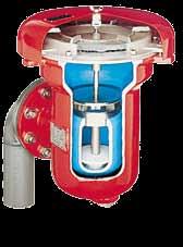
19 Technical Fundamentals Pressure and Vacuum Relief Valves Valves Development Closed vessels or tanks filled with liquid products must have an opening through which the accumulated pressure can be released so that the vessel does not explode. Along the same lines, a vacuum has to be compensated for when the tank or vessel is drained so that it does not implode. Unallowable overpressure and negative overpressure will accumulate with loading and unloading procedure, steam cleaning processes, blanketing and thermal effects. Free openings enable a free exchange with the atmosphere or with connected pipe systems that are uncontrolled and unmonitored. Vent caps are used in this case (Fig. 1). Valve Technology PROTEGO pressure and vacuum relief valves have weightloaded or spring-loaded valve pallets. When there is excess pressure in the tank, the pressure valve pallet guided in the housing lifts and thereby releases the flow into the atmosphere (Fig. 3a) until the pressure falls below the set pressure. The valve then reseats. The vacuum side of the valve is tightly sealed by the additional overpressure load. When there is a vacuum in the tank, the overpressure of the atmosphere lifts the vacuum disc and the tank is vented (Fig. 3b). Figure 1: Free venting of the storage tank with PROTEGO EH/0S The vented product vapours can be poisonous, odorous, flammable, or simply represent the loss of product. They pollute the atmosphere. Figure 3a: Operation of the valve under pressure in the tank The local concentration of chemical and processing plants and the associated environmental pollution have increased so much over the last 50 years, that valves are now to be used, especially in industrially developed countries, to keep the free opening cross-sections closed during operation and only permit emergency venting or relief. The ventilation devices, which are in the form of pressure and vacuum relief valves, should not be shut off (Fig. 2). Figure 3b: Operation of the valve under vacuum (negative pressure) in the tank Figure 2: Venting of the storage tank with pressure and vacuum relief valve PROTEGO VD/SV These valves need to be simple and robust valves that do not require remote control, are trouble-free and reliably fulfill expected tasks: Maintaining and compensating pressure and vacuum. Figure 4: PROTEGO full-lift pallet with air cushion seal In principle, the diaphragm valve, which is loaded with liquid (as a weight), and the pilot-valve, which is self-controlled, operate in the same manner. The weight-loaded valve pallets have different designs. A distinction is made between the full-lift pallet (Fig. 4 and Fig. 5 a, b) and the normal pallet (Fig. 6). KA / 1 / 0218 / GB 19
.")
 and hence meets the stringent demands of emission control regulations.")
20 Technical Fundamentals Pressure and Vacuum Relief Valves The sealing between valve pallet and valve seat is provided by an FEP air cushion seal, a metal to metal sealing, or PTFE flat sealing depending on the set pressure or on the application. The best sealing is obtained with a metal valve disc lapped to be seated on the metal valve seat (metal to metal). When the set pressures are low, an FEP air cushion seal provides a tight seal. The tightness of the PROTEGO valves is far above the normal standard (API2000 resp. EN ISO 28300) and hence meets the stringent demands of emission control regulations. PROTEGO pressure and vacuum relief valves with full-lift pallet discharge the flow within 10% overpressure from the set pressure to a fully opened valve (full-lift). After the initial response, the rise in pressure is proportional to the discharged flow up to a full lift. When the back pressure in the connected pipeline is high or the valve is installed in combination with a pressure control valve, this method provides greater stability for the overall system. However, the overall flow performance is not as good as that of valves with full-lift valve pallets. These valve pallets (Fig. 6) are primarily used in in-line valves when required by operating conditions. Depending on the design of the valve and the valve pallets, the design pressure and design vacuum (negative gauge pressure) is achieved with different overpressure (Fig. 7). Unless otherwise agreed, the standard PROTEGO valve design is for 10% technology. closed Discharge with full-lift Advantages of PROTEGO 10% technology: Pressure conservation very close to the maximum allowable tank pressure Minimization of product losses Reduction of vapour emissions Figure 5a: Discharge with full-lift pallet and air-cushioned seal Tank pressure Design point closed Discharge with full-lift overpressure Figure 5b: Discharge with full-lift pallet and metal seal This is attained by precisely harmonizing the diameter and height of the valve pallet rim with the adapted, machined and lapped valve seat. In addition, the flow-enhancing design reinforces the overall effect on the outflow side. These valve pallets are used in end-of-line and in-line valves. PROTEGO pressure and vacuum relief valves with conventional pallets discharge the flow within a 40% pressure. closed Discharge with full lift Figure 6: Discharge with normal pallet (flat with metal seal) Overpressure 10%: valve is closed up to 18 mbar Overpressure 100%: valve opens at 10 mbar already Figure 7: Opening characteristics of valves with different overpressure levels The PROTEGO diaphragm valve (Fig. 8) has a liquid load above the diaphragm. The static liquid column is an indication of the set pressure. The flexible liquid-loaded diaphragm adjusts tightly to the metallic valve seat to provide an excellent seal. If the set pressure is exceeded, the diaphragm lifts and releases the cross-section for the flow to discharge. Due to the flexible diaphragm, these valves are used in weather-related low temperatures and in sticky, polymerizing media. PROTEGO diaphragm valves are the only valves worldwide which are frostproof down to temperatures of -40 C (-40 F). Design flow 20 KA / 1 / 0514 / GB


21 pressure can be maintained with safety valves that are not subject to the regulations of Pressure Equipment Directive (PED). They need to meet other criteria however: Provide a good seal, be frostproof, trouble-free and easy to maintain. PROTEGO pressure and vacuum conservation valves meet these requirements while being highly efficient, operate stable and offer safe function even at very low pressures due to the 10% technology. In addition emissions of the products are reduced. Figure 8: Diaphragm Valve PROTEGO UB/SF-0 The self-controlled PROTEGO pilot operated valve (Fig. 9) discharges the flow without requiring additional overpressure. Up to the set pressure until the pilot reacts, the valve remains sealed; it immediately opens in a full-lift after the set pressure is reached without overpressure and releases the cross-section of the valve (set pressure = opening pressure). As the pressure increases, the seal increases up to the set pressure. Once the flow is discharged and the pressure falls below the opening pressure, the valve recloses. PROTEGO pilot valves are generally used as safety relief valves for low-temperature storage tanks or wherever the valve must be very tightly sealed up to the set pressure. National and international technical regulations for maintaining clean air serve as the basis for calculating savings (such as VDI 3479: Emission Control - Marketing Installation Tank Farms, VOC Directive 1999/13/EC and 94/63/EC or API MPMS Chapter 19.1: API Manual of Petroleum Measurement Standards - Chapter 19, Evaporative Loss Measurement, Section 1 - Evaporative Loss from Fixed-Roof Tanks, 3 rd Edition ). The design of the tank, the paint, the insulation, and pressure maintenance via the valves influence - among others - the reduction of emissions. The effect that pressure maintenance has on the reduction of product (vapour) loss improves as the set pressure of the valve approaches the maximum allowable tank pressure. The flow needs to be reliably discharged without the tank rupturing. A comparison of product loss at different overpressures clearly reveals the advantages of the 10% technology over the 40% overpressure and especially in contrast to a 100% overpressure: The specially developed design yields measurable savings by decreasing the accumulation up to the required performance (Fig. 10). 80 Emission reduction at a petrol storage tank with 20 mbar max. allowable tank pressure and different valve technologies 70 Figure 9: pilot operated pressure relief valve PROTEGO PM/DS The operating requirements regarding the amount of outbreathing and inbreathing capacity determine whether separate pressure valves and vacuum valves or combined pressure and vacuum relief valves are used. Pressure and vacuum relief valves for maintaining pressure (vapour conservation) Process-dependent pressure maintenance in systems is ensured by valves that take pressure vessel related parameters into consideration. Conventional safety valves are used for pressures above 0.5 barg (7.25 psig) according to EN-ISO 4126 and Pressure Equipment Directive (PED), API 526 and ASME VIII, Div.1, or other international standards. For pressures below 0.5 barg (7.25 psig), the % Emmission reduction %=71% maximum theoretical saving 10% PROTEGO Technology (fulllift disc, set pressure 18 mbar) = 65% saving 40% Technology (normal disc, set pressure 14 mbar) = 51% saving 100% Technology (set pressure 10 mbar) = 35% saving Figure 10: Stored product Petrol: Comparison of product savings at different overpressure levels versus the free vented storage tank: Example of product loss at 20 mbar allowable tank pressure savings in % at different overpressure 0% = up to 20 mbar (8 inch W.C.) the valve is closed (theoretical): more than 70% saving, 10%= only at a valve set pressure 18 mbar (7.2 inch W.C.) the valve opens, 65% saving, 40%= at a valve set pressure 14 mbar (5.6 inch W.C.) the valve opens, 51% saving, 100%=already at a valve set pressure 10 mbar (4 inch W.C.) the valve opens: only 35% saving. KA / 1 / 0316 / GB 21
. These influences must be considered in addition to filling and emptying capacities as well as inert-gas supply.")
22 Technical Fundamentals Pressure and Vacuum Relief Valves Pressure and Vacuum Relief Valves for Pressure Relief and Tank Breathing Outdoor storage tanks and vessels are exposed to weather conditions such as heating up and cooling down (the tank must be able to breath). These influences must be considered in addition to filling and emptying capacities as well as inert-gas supply. They can be calculated with good approximation (see Venting Requirements of Aboveground Storage Tanks - Sizing and Calculation Formulas, Page 26). The valve opening pressure must not exceed the maximum allowable tank pressure which also is called the tank design pressure. The construction and design of the valve determines how this opening pressure is reached. Safety valves with conventional construction designed for pressure vessels with 0.5 bar (7.25 psi) overpressure require an overpressure of 10% above the set pressure to attain the opening pressure. Below 1 bar (14.5 psi) pressure, the maximum overpressure may reach 100 mbar (4 inch W.C.), which is clearly above the 10% level. In contrast, PROTEGO valves with the relevant technology meet the requirements of conventional safety valves with an overpressure of 10% even at low set pressures down to bar (1.2 inch W.C.). Under normal operating conditions, it must be impossible to block off the venting system on the tank. The sizing of the pressure and vacuum relief system must be such, that the design pressure, i.e. the pressure and vacuum (negative pressure) in the tank, can not be exceeded under any operating conditions. The pressure and vacuum relief valve must be designed for maximum flow arising from the pump capacity, thermal and other influences. This valve is frequently called the vent valve. When extremely high venting rates are required due to fire on the outside surface of the tank or malfunctions in special tank equipment (such as tank blanketing gas systems), additional emergency pressure relief valves must be used, especially when the tank roof does not have a weak seam (Fig. 11). When a blanket gas system fails, large amounts of gas can flow into the tank. The excess gas must be discharged from the tank through the pressure relief system without exceeding the tank c design pressure. b a d Figure 11: Venting of the storage tank with a pressure and vacuum relief valve PROTEGO VD/SV-PA (a), piped into the vent header during operation (b), venting during operation via the nitrogen control valve PROTEGO ZM-R (c), relieving in a fire-case through the emergency pressure relief valve PROTEGO ER/V (d) PROTEGO valves fulfill the above metioned functions of maintaining and relieving pressure as pressure relief valves, vacuum relief valves, or combined pressure and vacuum relief valves. Location of installation In general, PROTEGO end-of-line valves are used for storage tanks, vessels or for ventilation lines. In pipes, PROTEGO inline valves are used as overflow valves, for backflow prevention and occasionally as control valves. The great advantages are their simple design and large opening cross-sections. These valves operate trouble-free. If the flowing products are explosive, in-line valves must have upstream flame arresters to protect the system against accelerated combustions. End-of-line valves in this case of hazardous application, must be equipped with an end-of-line flame arrester to protect the system against atmospheric deflagration (see also Vol. 7). Sizing of the Valves The maximum possible volumetric flow, the maximum permissible pressures, and the operating data (process parameters) must be taken into account when sizing pressure/ vacuum relief valves. Definitions: Set pressure = the valve starts to open = adjusted set pressure of the valve at 0 bar back pressure Opening pressure = set pressure plus overpressure Reseating Pressure = Closing pressure = the valve recloses and is sealed Overpressure = pressure increase over the set pressure Accumulation (ISO) = pressure increase over the maximum allowable tank pressure of the vessel allowed during discharge through the pressure relief valve Accumulation (EN) = differential pressure between the set pressure of the valve and the tank pressure at which the required flow rate is reached or the set vacuum of the valve and the tank internal negative pressure at which the required flow rate is reached (not used in this catalog) Pressure loss = decrease in pressure within the valve at a given flow Pressure loss curve (Flow Chart) = performance curve in the flow chart = the characteristics of the valves as the pressure in mbar (inch W.C.) plotted against the flow in m 3 /h (cfh) Back pressure = pressure in the system, that acts against the flow out of the valve and that needs to be included as additional pressure on the valve pallet The maximum allowable design pressure of an equipment, storage tank or vessel may not be exceeded. The maximum possible flow must be reliably discharged through the valve so that the maximum allowable design pressure of the equipment is not exceeded. Safety factors must be taken into account. 22 KA / 1 / 0514 / GB
. When the design flow is not being reached during discharge the valve does not open completely.")
23 Operating states of pressure and vacuum relief valves: The valve is optimally sized when the operating point lies on the performance curve, i.e., when the attained maximum flow is discharged with the valve completely open without requiring an additional overpressure (with completely open valve) (full-load operating range A, Fig. 12). When the design flow is not being reached during discharge the valve does not open completely. The valve pallet only lifts briefly, discharges the volume, and then recloses when the pressure falls below the set pressure. The reseating pressure depends on the design of the valve pallet and the geometry of the valve. There are partial-load operating ranges in which the full-lift is not reached (over-sized valves) and overload ranges in which an additional overpressure is required after a full lift to discharge the flow (under-sized valves). Within the overload range, the valve is stable; in the partial load range, the valve pallet can flutter due to instability. A proper sizing that takes possible operating conditions into consideration is therefore essential. Opening pressure resp. tank pressure (mbar) over-load operating range Po Partial-load operating range Flow (m 3 /h) opening pressure resp. tank design pressure set pressure = overpressure % % Figure 12: Design and operating points in the flow chart Example (Fig. 12): Valve opening pressure P o = 20 mbar Valve set pressure P set = 18 mbar (20 mbar - 10%) A design flow design = m 3 /h B over-load > design C partial-load Selection < design For sizing of combined single component devices, which have not been flow tested as combined devices (e.g. DR/ES with DV/ZT), a special sizing process needs to be considered. Please contact our sales engineers for specific guidance. The valves are selected using the above selection criteria depending on the location of installation and whether the valve is to function as a pressure relief valve, vacuum relief valve, or combined pressure and vacuum relief valve. Location of End-of-line Valves In-line Valves Installation Function Example of Use Pressure Relief Valves Vacuum Relief Valves Pressure and Vacuum Relief Valves Pressure Relief and Vacuum Valves, pilot operated Pressure or Vacuum Relief Valves Pressure and Vacuum Relief Valves Storage tank, page 35 Vent header, page 35 Blanketing Valves Product Volume 5 Volume 5 Volume 5 Volume 5 Volume 6 Volume 6 Volume 6 PROTEGO has the right valve for all applications For venting of storage tanks and vessels PROTEGO Pressure and Vacuum Relief Valves, end-of-line (Vol. 5) As overflow valves or backflow preventers PROTEGO Pressure or Vacuum Relief Valves, in-line (Vol. 6) For venting of tanks storing products at low temperatures and storing critical products PROTEGO Pressure / Vacuum Relief Diaphragm Valves, end-of-line (Vol. 5) KA / 1 / 0311 / GB 23

.")
24 Technical Fundamentals Pressure and Vacuum Relief Valves with Flame Arresters Development When storing flammable products or processing chemical products that can create explosive mixtures, the opening of the storage tank or vessel must be additionally protected with flame arresters. The task was to develop a device that combined the properties of a flame arrester and a valve into one design. PROTEGO valves with integrated flame arrester units have the unique advantage that the flame arrester units are external and hence easily accessible (Fig. 1 and 2). Figure 1: Deflagration-proof pressure and vacuum relief valve PROTEGO VD/TS Pressure and Vacuum Relief Valves with Flame Arrester Pressure and vacuum relief valves with integrated flame arrester units have the same tasks and functions as valves without flame arrester. They serve to maintain pressure (vapour conservation), relief pressure and enable tank breathing. For a detailed description, see page 21. Flame Arrester The valves also have an integrated flame arrester unit. The explosion group of the chemical products to be protected needs to be considered in the flame-transmission-proof selection of the valve. The chemical products are categorized into explosion groups according to the maximum experimental safe gap (MESG) of the mixtures. The valve is tested and approved for the explosion group. The PROTEGO diaphragm valve (Fig. 3) has a liquid load above the diaphragm. The static liquid column is proportional to the set pressure. The flexible liquid-loaded diaphragm adjusts tightly to the metal valve seat to provide an excellent seal. If the set pressure is exceeded, the diaphragm lifts and releases the cross-section for the discharging flow. Due to the flexible diaphragm, these valves are used in weather-related low temperatures and for sticky, polymerizing media. The PROTEGO diaphragm valve (Fig. 3a) offers dynamic flame-transmission protection against endurance burning and atmospheric deflagrations. Figure 2: Pressure and vacuum relief valve protecting against deflagration and endurance burning PROTEGO VD/SV-HR The operating conditions must be carefully considered. Depending on the possible combustion processes, protection must be provided against atmospheric deflagration, and/or short time burning, and/or endurance burning. Valve Technology Figure 3: Diaphragm valve PROTEGO UB/SF protecting against deflagration and endurance burning The valve technology and function of the pressure and vacuum valves with integrated flame arrester units are equal to those without flame arrester units. It must be realized that the downstream flame arrester unit creates a certain back pressure which has no impact on the set pressure but influences the overpressure behaviour. This is considered in the flow charts. 24 KA / 1 / 0316 / GB
 has special flame-transmission protection with a dynamic discharge between the valve cone and valve seat starting at a set pressure of +60 mbar (24 inch W.C.). The high velocity valve is endurance burning proof.")


25 Figure 3a: Endurance-burning test with diaphragm valve PROTEGO UB/SF The high velocity valve (Fig. 4) has special flame-transmission protection with a dynamic discharge between the valve cone and valve seat starting at a set pressure of +60 mbar (24 inch W.C.). The high velocity valve is endurance burning proof. Location of installation Valves with flame arrester units are always end-of-line valves since the heat must be released to the environment with no heat build-up to prevent transmission of flame. Otherwise the unallowable heat build-up would effect a heat accumulation at the flame arrester which finally results in a flash-back. They are primarily used for storage tanks and containers in which flammable liquids are stored or processed and for relief openings in process containers in which the occurence of explosive mixtures cannot be excluded. Design and operating states of valves The sizing and operating states of the pressure and vacuum relief valves are described on pages 22 and 23. Selection Since PROTEGO pressure/vacuum relief valves with flame arrester units are always end-of-line valves, they are selected taking into consideration their function as a pressure valve, vacuum valve, or combined pressure and vacuum relief valve. After the explosion group of the products and the possible combustion process have been determined, the valve can be selected regarding its flame-transmission protection. When selecting PROTEGO valves with a flame arrester unit, one must establish whether flame-transmission protection is to be provided against atmospheric deflagrations or endurance burning. Endurance burning flame arresters include protection against atmospheric deflagrations. Flame-transmission-proof vacuum relief valves are deflagration-proof. The danger of a stabilized burning does not exist for vacuum relief valves. Figure 4: Endurance burning-proof high velocity valve PROTEGO DE/S with a connected deflagration-proof vacuum valve PROTEGO SV/E-S Location of Installation End-of-line Valve Function Pressure Relief Valve with Flame Arrester Vacuum Relief Valve with Flame Arrester Pressure and Vacuum Relief Valve with Flame Arrester Pressure- / Vacuum Relief Diaphragm Valve with Flame Arrester High Velocity Valve Example of Use Storage tank, Emergency venting / pressure relief, page 35 Storage tank, Tank ships, page 38 Products Volume 7 Volume 7 Volume 7 Volume 7 Volume 7 PROTEGO has the right valve for all applications. For flame-transmission-proof pressure and vacuum relief of storage tanks and containers PROTEGO Pressure and Vacuum Relief Valves with Flame Arresters, end-of-line For frost-proof application, for critical products, and for flametransmission-proof pressure and vacuum relief of tanks and containers PROTEGO Pressure -/ Vacuum Relief Diaphragm Valves For flame-transmission-proof pressure and vacuum relief of tank ships PROTEGO High Velocity Valves KA / 1 / 0514 / GB 25

26 Technical Fundamentals Venting Requirements of Aboveground Storage Tanks - Sizing and Calculation Formulas Pressure Terms and Definitions Tanks storing flammable and non-flammable liquids are designed and manufactured in accordance to different standards: EN 14015, API 620 or API 650 are the most important standards worldwide. Depending on the standard different maximum tank pressures are allowable to relief the required massflow. Fig. 1 shows the most common terms for tanks and valves. This comparison clarifies the sizing of end-of-line relief valves featuring the 10% overpressure technology with a set pressure Figure 1: Comparison of pressure terms for storage tanks and vent valves designed and manufactured in accordance to different standards (e.g. API 620 or API 650 or EN 14015) equipped with pressure relief devices (illustration simplified and based on 10% overpressure technology of the valve). The different definition of the term accumulation is explained on Page 22. adjusted only 10% below the opening pressure. In accordance to EN and API 650 (Fig. 1A and 1B) the design pressure or MAWP = Maximum Allowable Working Pressure of the tank must not be exceeded not even in fire-case or system mal-function. Following API 620 (Fig. 1C) the valve must relief the required regular massflow out of thermal influences and pumping at 10% above the design pressure (in general the MAWP) at the latest. For fire-case or emergency an overpressure of 20% is allowable: after exceeding the MAWP by maximum 20% the required emergency massflow must be Tank API 620 p Valve EN API 650 MAAP (Fire) 120 opening pressure for fire Tank Valve Tank Valve p p testpressure for tanks with p>10mbar MAAP (Operating) 110 opening pressure accumulation design pressure = test pressure for tanks with p<10mbar 100 opening pressure overpressure Internal Design Pressure 100 opening pressure overpressure MAWP (Design) 100 set pressure blow down operating pressure (< design pressure) 90 set pressure blow down OPP (< Internal Design Pressure) 90 set pressure blow down OPP (< MAWP) 90 reseating pressure reseating pressure reseating pressure % of design pressure = p = % of opening pressure design pressure = calculated pressure = Maximum Allowable Working Pressure (MAWP) to be not exceeded at all operating conditions. For fire and emergency conditions weak roof to shell attachment or emergency relief valves to be provided. opening pressure < design pressure; set pressure = 0,9 x opening pressure for 10% overpressure technology. Figure 1A internal design pressure = max. relieving pressure under operating condition, fire condition or emergency (max. relieving pressure for valve and emergency valve). OPP = Operating Pressure % of MAWP = p = % of opening pressure opening pressure < internal design pressure set pressure = 0,9 x opening pressure for 10% overpressure technology. Figure 1B % of MAWP = p = % of set pressure MAAP = Maximum Allowable Acumulated Pressure = max. relieving pressure under operating condition (max. relieving pressure for valve). Relief Pressure for fire-case or emergency condition relief at 20% excess overpressure. Max. allowable set pressure = MAWP for 10% overpressure technology. MAWP = Maximum Allowable Working Pressure Figure 1C 26 KA / 1 / 0514 / GB
27 Engineering Service QuEST - Quick Engineering and Sizing Tool relieved. Fig. 2 shows the procedure to determine the set pressure for valves with different overpressure characteristics by considering the specific tank design pressure. These examples are for end-ofline relief valves only without a back-pressure originated by e.g. connected pipe-away-line. If the tank is designed in accordance to EN or API 650 the opening pressure must not exceed the design pressure (=MAWP) of the tank (Fig. 2A). The set pressure is a result of the opening pressure minus the overpressure of the valve which is a characteristic of the specific valve. If the tank is manufactured in accordance to API 620 the opening pressure may exceed the tank design pressure by 10% for regular breathing and 20% for fire-case (Fig. 2B). The set pressure again is the result of the opening pressure minus the valve-characteristic overpressure. Figure 2: Selection of the set pressure of the Pressure or Vacuum Relief Valve considering the tank design pressure and the valves characteristic overpressure (e.g. 10%, 40% or 100%). API 620 using the 20% overpressure allowance for fire emergency. API 620 Tank Valve Pressure Relief Valve / Vacuum Relief Valve Emergency Relief Valve % 10% 40% 100% 20% EN / API 650 MAAP (Fire) 120 opening pressure for fire Tank Valve Pressure Relief Valve / Vacuum Relief Valve MAAP (Operation) 110 opening pressure % 10% 40% 100% PROTEGO 10% Technology accumulation accumulation design pressure PROTEGO 10% Technology set pressure for 10% overpressure opening pressure max. allowable overpressure in accordance to DIN/TRbF MAWP (Design) set pressure for 10% overpressure reseating pressure overpressure (conventional vent valves) set pressure for fire overpressure (conventional vent valves) 80 reseating pressure overpressure (conventional vent valves) 80 set pressure for 40% overpressure 70 set pressure for 40% overpressure 70 reseating pressure reseating pressure set pressure for 100% overpressure 50 set pressure for 100% overpressure 50 reseating pressure 40 Figure 2A: Design in acc. to EN or API 650 reseating pressure 40 Figure 2B: Design in acc. to API 620 KA / 1 / 0218 / GB 27
28 Technical Fundamentals Venting Requirements of Aboveground Storage Tanks - Sizing and Calculation Formulas Calculation of the Out- and Inbreathing venting capacity in acc. to ISO 28300/API 2000: The maximum required venting capacity is the total amount of pump capacity and capacity out of thermal influences: V. out = V. thermal out + V. pump in V. in = V. thermal in + V. pump out The calculation of the maximum required capacity out of the thermal influences is based on ISO with regard to aboveground storage tanks with or without insulation. Thermal capacity for heating up V. in V. thermal out m3 /h = 0,25 V 0.9 thermal out Tank R i Thermal capacity for cooling down V. in V. thermal in m3 /h = C V 0.7 thermal in Tank R i V Tank is the volume of the tank in m 3 V tank = 0,7854 D 2 H R i is a reduction factor for insulation (see ISO 28300/API 2000) V. is the filling rate to calculate the outbreathing capacity out of the maximum pump capacity in m³/h for products pump in stored below 40 C and a vapour pressure p vp < 50 mbar. For products stored at a temperature above 40 C or with a vapour pressure p vp > 50 mbar the out-breathing rate must be increased by the evaporation rate. V. is the emptying rate to calculate the inbreathing capacity of the pump in m 3 pump out /h. C=3 for products with equal vapour pressure as hexane and storage temperature < 25 C C=5 for products with vapour pressures higher than hexane and/or storage temperature above 25 C (if vapour pressure not known, then C=5) The mentioned calculation formulas are valid for latitudes 58 to 42 ; other latitudes see ISO 28300/API Particular influences to be considered are e.g.: Failure of the nitrogen blanketing valve Installation of an additional emergency relief valve to vent the non calculated flow which was not foreseen under operation Filling the empty hot tank with cold liquid product Considering the additional flow due to the sudden cooling down when calculating the necessary vacuum capacity Exceeding the maximum given pump out capacity Considering a safety factor when calculating the required inbreathing capacity Calculation of the Out- and Inbreathing venting capacity in acc. to TRGS 509: To calculate the out- and inbreathing capacity of storage tanks (e.g. tanks in acc. to DIN 4119 aboveground storage tanks or DIN 6608 horizontal underground or buried tanks) the calculation formulas of TRGS 509 (since 1 January 2013 VdTÜV- Merkblatt Tankanlagen 967) are to be applied. Calculation of the required capacity due to thermal influences: Heating up V. H -0,52 0,89 E = 0,17 x D x V Tank V. 0,71 Cooling down A = 4,8 x V Tank H = Height of the Tank in m; D = Diameter in m Calculation of Out- and Inbreathing venting capacity in acc. to API th edition / ISO Annex A: The out- and inbreathing capacity of petroleum storage tanks can be calculated in acc. to ISO Annex A (approximately equivalent to API th edition) if specific boundary conditions are fulfilled (see ISO 28300). If required and when the tanks are specified and designed in accordance to API 650, the venting capacity is to be calculated in accordance to API 2000 for in- and outbreathing as well as for emergency fire cases. When calculating the required capacities in accordance to API th edition / ISO Annex A, the flammable liquids must be verified with regard to their flashpoint. Different formulas must be applied for liquids with flashpoint < 100 F (< 37,8 C) and for liquids with flashpoint > 100 F (> 37,8 C). The maximum required venting capacity is the total amount of pump capacity plus capacity out of thermal influences. In contrast, the calculation of the pump capacity must consider a factor for the inbreathing rate and the different flashpoints for the outbreathing rate. Calculation of the inbreathing capacity: V. = V. x 0,94 + V. in pump out thermal in 28 KA / 1 / 0917 / GB
29 Calcuation of emergency venting capacity according to API th edition and ISO QuEST - Quick Engineering and Sizing Tool The thermal capacity thermal In is rated in API th ed. Fig. 2A (English Units) and 2B (Metric Units) depending on the tankvolume. The maximum pumping capacity V. is rated in accordance to the specified operating rates for pump out emptying. Calculation of the outbreathing capacity: For liquids with flashpoint <100 F (<37,8 C) V. = V. x 2,02 + V. out pumping in thermal out For liquids with flashpoint >100 F (>37,8 C) V. = V. x 1,01 + V. out pumping in thermal out The thermal capacity V. thermal out is rated in API th ed. Fig. 2A (English units) and 2B (Metric Units) depending on the tankvolume and the flashpoint. The maximum pumping capacity V. is rated in accordance to the specified operating rates pump in for filling. In case there is no weak roof-to-shell attachment, the venting for fire emergency case is to be realized through an emergency pressure relief valve. The required capacity for fire emergency case V. is rated in accordance to API 2000 Fig. 3A (English Fire Units) and Fig. 3B (Metric Units) depending on the wetted surface area of the tank. Simplified formula for estimating calculation: V. fire = 208,2 x F x A 0,82 for Metric Units in Nm 3 /h V. fire = 1107 x F x A 0,82 for English Units in SCFH Insulation is considered with a factor F in API 2000 Fig. 4A (Englisch Units) and 4B (Metric Units). Requirements of Thermal Venting Capacity (English Units) Requirements of Thermal Venting Capacity (Metric Units) Tank Capacity Tank Capacity Inbreathing thermal in Outbreathing thermal Out Flashpoint Flashpoint > 100 F < 100 F Tank Capacity Inbreathing thermal in Outbreathing thermal Out Flashpoint Flashpoint > 37,8 C < 37,8 C Barrels Gallons SCFH Air SCFH Air SCFH Air m 3 Nm 3 /h Nm 3 /h Nm 3 /h ,69 1,01 1, ,37 2,02 3, ,90 10,10 16, ,70 20,20 33, ,60 30,30 50, ,30 50,60 84, ,00 101,00 169, ,00 202,00 337, ,00 303,00 506, ,00 388,00 647, ,00 472,00 787, ,00 726, , , , , , , , , , ,00 Excerpt of API th ed. Figure 2A Excerpt of API th ed. Figure 2B KA / 1 / 0218 / GB 29
30 Technical Fundamentals Venting Requirements of Aboveground Storage Tanks - Sizing and Calculation Formulas Emergency Venting required for Fire Exposure Versus Wetted Surface Area (English Units) Emergency Venting required for Fire Exposure Versus Wetted Surface Area (Metric Units) Wetted Area A square feet Excerpt of API th ed. Figure 3A Venting Requirement V. SCFH Wetted Area A Venting Requirement V. m 2 Nm 3 /h Excerpt of API th ed. Figure 3B Environmental Factors for nonrefrigerated Aboveground Tanks (English Units) Tank-configuration Insulation F - Factor Thickness inch Environmental Factors for nonrefrigerated Aboveground Tanks (Metric Units) Tank-configuration Insulation F - Factor Thickness cm Bare metal tank Bare metal tank 0 1,0 insulated tank insulated tank 2,5 0,3 insulated tank insulated tank 5 0,15 insulated tank insulated tank 10 0,075 insulated tank insulated tank 15 0,05 underground storage 0 underground storage 0 earth covered storage 0.03 earth covered storage 0,03 impoundment away 0.5 impoundment away 0,5 from tank from tank Excerpt of API th ed. Excerpt of API th ed. Figure 4A Figure 4B 30 KA / 1 / 0909 / GB
31 Conversion of operational flow into equivalent diagram flow for use of flow charts To use the flow charts (pressure vs. flow diagram) by considering the operational and product data, it is necessary to convert the given operational flow V. into the equivalent diagramflow V.. This V. then creates the same pressure loss as the B,Gas Dia Dia actual operational flow. 1) Conversion of the operational flow V. into the standard B,Gas flow V. : N,Gas V. = V. T * = V. N * p B p B * 273,15K N, Gas B, Gas B, Gas T * B * p N T B * 1,013 bar abs. 2) Conversion of the standard flow V. N,Gas diagram flow V. : Dia V. p V. = N, Gas * N, Gas *p N *T B Dia pdia *p G *T N into the equivalent =V. N, Gas* pn, Gas *T B * 1,013 bar abs. kg pg * 1,2 m * 273,15 K 3 3) Calculation of the average density p N,Gas of a gas-mixture p N, Gas = (v 1 * p N, Gas 1 + v 2 * p N, Gas v x * p N, Gas x ) Terms V. = Flow m 3 /h (CFH) p = Pressure bar abs (psi abs) T = Temperature K p = Specific density kg/m 3 (lb / cu ft) v = Volume fraction Indices N = Standard condition (at 1,013 bar abs and 273,15 K) B = Operational condition (pressure and temperature in acc. to operation) Gas = Dia = Actual product Related to the Diagram, when using the flow chart for sizing (p Dia =1,189 kg/m 3 related density of air at 20 C and 1 bar abs.) G = related to the outlet of the device ( p G back pressure) for operating conditions KA / 1 / 0514 / GB 31
32 Technical Fundamentals Venting Requirements of Aboveground Storage Tanks - Sizing and Calculation Formulas Safety Proceeding to Protect Hazardous Explosive Areas in Third-Party-audited processing plants Step 1 Assessment of the possible combustion process based on Standards, e.g. EN General Explosion Protection Methods and EN ISO respectively EN Flame Arresters Deflagration in the atmosphere, in a pre-volume or in a pipeline Detonation in a pipeline, stable or unstable Endurance burning due to continous flow of vapours/gases in the pipeline or at the opening of a tank Step 2 Classification of the products based on literature and international standards EN ISO 16852, VbF, NFPA, British Standard for liquids, gases, vapours and multiple component mixtures Liquids: subdividing in flammable, easy flammable and highly flammable due to the flash point of the liquid and verifying the ignition temperature. The classification is following the VbF (previously) and the Ordinance on Hazardous Substances (Gef. Stoff VO): Non water soluble previous actual (A I FP< 21 C) FP < 0 C (32 F) Extremely flammable FP < 21 C (70 F) Highly flammable (A II FP C) FP C ( F) Flammable (A III FP C) - Water soluble previous actual (B < FP 21 C) FP < 0 C (32 F) Extremely flammable FP < 21 C (70 F) Highly flammable FP C ( F) Flammable FP = Flashpoint Products with a flashpoint FP>55 C (>131 F) get flammable when being heated close to the flashpoint ( T = 5 degree safety margin as a rule of thumb for hydrocarbons as well as 15 degree for mixtures). Vapours: classification of the gas/vapour-air-mixtures in accordance to the MESG of the products or the mixture into the Explosion Groups IIA1, IIA, IIB1, IIB2, IIB3, IIB and IIC (page 17) (NEC Group D, C and B). Step 3 Consideration of the operational process parameters of the unburnt mixtures with regard to the impact on the combustion behaviour: OperatingTemperature < 60 C (< 140 F) Standard, no particular requirements > 60 C (> 140 F) Special approvals necessary Operating pressure < 1,1 bar abs(< psi) Standard, no particular requirements > 1,1 bar abs(> psi) Special approvals necessary Step 4 Assessment of the overall system and classification into hazardous zones in accordance to frequency and duration of explosive atmosphere based on national and international regulations e.g. TRBS, IEC or NFPA/NEC. Zone 0 A place in which an explosive atmosphere consisting of a mixture of air with flammable substances in the form of gas, vapour or mist is present continuously or for long periods or frequently. Zone 1 A place in which an explosive atmosphere consisting of a mixture of air with flammable substances in the form of gas, vapour or mist is likely to occur in normal operation occasionally. Zone 2 A place in which an explosive atmosphere consisting of a mixture of air with flammable substances in the form of gas, vapour or mist is not likely to occur in normal operation but, if it does occur, will persist for a short period only. To work out a risk assessment, the possible ignition sources must be evaluated under normal operating conditions as well as under special operating conditions like cleaning and maintenance work (see EN ): effective ignition source: Steady and continuously under normal operation Solely as a result of malfunctions Solely as a result of rare malfunctions Effective ignition sources are chemical reactions, flames and hot gases, hot surfaces, mechanical generated sparks, static electricity, lightning, electromagnetic waves, ultrasonics, adiabatic compression, shock waves etc. Effectiveness of the ignition source is to be compared to the flammability of the flammable substance. 32 KA / 1 / 0316 / GB
33 Step 5 Selection, number and location of the suitable Equipment, Protective System and Component must follow the requirements of national and international regulations (ATEX Directive). For equipment (blowers, agitators, containers etc.) In Zone 0 equipment categorized in group II cat 1 In Zone 1 equipment categorized in group II cat 2 In Zone 2 equipment categorized in group II cat 3 Flame arresters tested accordingly to EN ISO resp. EN fullfil the health and safety requirements of current ATEX directive. Flame arresters are Protective Systems and are not categorized. They must be type examination tested and approved by a Notified Body. They can be installed in all zones (zone 0, 1 or 2) and are marked with CE to state the conformity with all applicable requirements. The procedure and the results of the risk assessment must be verified in the Explosion Protection Document. The plant operator (employer) has to confirm that Equipment, Protective Systems and Components are in accordance with the law and are in compliance with the actual state-of-the-art. Process engineering, plant-layout, substances, zoning, risk assessment etc. are part of the protection concept and are determined in connection with the corresponding responsibilities. KA / 1 / 0316 / GB 33

34 Safe Systems in Practice Overview Applications PROTEGO safety devices are used in a wide range of industrial applications. A safe process requires reliable protection for every conceivable operating parameter. Practical examples show how systems can be made safe and how PROTEGO devices can be incorporated into control loops. Engineers are responsible for properly harmonizing the overall system. 6 PROTEGO devices offer safety and environmental protection In Storage Tank Farms for Refineries and Chemical Plants In Processing Systems for Chemical and Pharmaceutical Industries In Vapour Combustion Systems and Flares In Ship Building and Loading Systems In Vapour Recovery Units As integrated Component of Equipment, Machines and Vessels Applications of PROTEGO devices are used in other areas such as in biogas and landfill gas systems, medical technology, food processing, airplane construction, automobile construction, IT clean-rooms, thin-layer manufacturing, etc. 34 KA / 1 / 0218 / GB

, liquid detonation flame arrester LDA-F ( Volume 4), in the protective gas blanket line DR/ES ( Volume 4) with DV/ZT ( Volume 6) Fixed-roof storage tank for")
, detonation-proof gas displacement connection DR/ES ( Volume 4) Fixed-roof storage tank for flammable liquids with")
 and in-line pressure and 5 6 7 vacuum safety relief valve DV/ZT or DV/ZW ( Volume 6), liquid detonation arrester in the filling line LDA-W and emptying line LDA-WF ( Volume 4) Fixed-roof")
, detonation flame arrester in the drain line DR/ES ( Volume 4), and in the vent line DR/ES ( Volume 4) and VD/SV ( Volume 5) Aboveground tank")
 ensures that the tank is not emptied, detonation proof foot valve for suction line EF/V ( Volume 4), detonation flame arrester DR/ES ( Volume 4) in vapour return pipeline.")
35 Safe Systems in Practice Storage Tanks in Tank Farms for Refineries and Chemical Processing Plants (exemplary) Storage Tanks P/EB EB EB AL/DK D/SR UB/SF DR/ES DV/ZT P/EB SV/E SV/E DR/ES SE/K LDA-F SA/S LDA-W LDA-WF VD/SV VD/SV-HRL DR/ES DV/ZW DV/ZT DR/ES UB/SF DR/ES LDA-W LDA-WF PV/EBR LDA-F VD/SV ER/V DR/ES 7 DA-G EF/V LDA Floating-roof storage tank with floating-roof drainage system SE/K ( Volume 8), roof valve D/SR ( Volume 8), stem-actuated valve AL/DK ( Volume 8) with deflagration flame arresters EB ( Volume 2) Fixed-roof storage tank for flammable liquids with pressure and vacuum diaphragm valve UB/SF ( Volume 7), liquid detonation flame arrester LDA-F ( Volume 4), in the protective gas blanket line DR/ES ( Volume 4) with DV/ZT ( Volume 6) Fixed-roof storage tank for flammable liquids with pressure safety relief valve P/EB ( Volume 7) and vacuum safety relief valve SV/E ( Volume 7), liquid detonation flame arrester LDA-W ( Volume 4) and/or LDA-W-F ( Volume 4) in the filling and emptying line, float-controlled swing pipe system SA/S ( Volume 8), detonation-proof gas displacement connection DR/ES ( Volume 4) Fixed-roof storage tank for flammable liquids with pressure and vacuum relief valve VD/SV-HRL ( Volume 7), pressure and vacuum relief diaphragm valve UB/SF ( Volume 7), connection to gas vent header system with detonation flame arrester DR/ES ( Volume 4) and in-line pressure and vacuum safety relief valve DV/ZT or DV/ZW ( Volume 6), liquid detonation arrester in the filling line LDA-W and emptying line LDA-WF ( Volume 4) Fixed-roof storage tank for non-flammable liquids with pressure and vacuum conservation valve VD/SV ( Volume 5) and emergency pressure relief valve ER/V ( Volume 5) instead of weak seam Underground storage tank with safety devices in the filling line LDA-F ( Volume 4), detonation flame arrester in the drain line DR/ES ( Volume 4), and in the vent line DR/ES ( Volume 4) and VD/SV ( Volume 5) Aboveground tank for flammable liquids with pressure and vacuum safety relief valve PV/EBR ( Volume 7), liquid detonation flame arrester LDA ( Volume 4) in the filling line and an additional detonation flame arrester DA-G ( Volume 4) ensures that the tank is not emptied, detonation proof foot valve for suction line EF/V ( Volume 4), detonation flame arrester DR/ES ( Volume 4) in vapour return pipeline. KA / 1 / 0218 / GB 35
, connection to gas vent header")
 Temperature-monitored deflagration flame arresters FA-I-T ( Volume 3) in the feed line for vapour combustion at the maximum allowable distance")
36 Safe Systems in Practice Chemical and Pharmaceutical Processing Facilities (exemplary) Chemical and Pharmaceutical Processing Facilities UB/SF DR/ES-V 5 UB/SF DR/ES DZ/T SV/T-0-SH SD/BS-SH DR/SE-SH DR/ES DR/ES 2 DR/ES DR/ES 3 FA-I-T 4 FA-I-V-T FA-I-P FA-I-T Tank farms for flammable liquids with pressure and vacuum relief diaphragm valve UB/SF ( Volume 7), connection to gas vent header system with detonation flame arrester DR/ES-V or DR/ES ( Volume 4) and pressure or vacuum relief valve DZ/T ( Volume 6) Ventilation of industrial mixers and process vessels in a common vapour vent header via detonation flame arresters DR/ES ( Volume 4) Temperature-monitored deflagration flame arresters FA-I-T ( Volume 3) in the feed line for vapour combustion at the maximum allowable distance from the ignition source and in parallel for the sake of availability for servicing or emergency switching in case of an endurance burning on the arrester. Vapour pipeline from plant to vapour combustion unit with deflagration flame arrester FA-I-T ( Volume 3) to protect the vent header collection line and the operating locations in the plant. 4 5 Protecting pressure-resistant radial blowers as typeexamined zone-0 blowers with integrated PROTEGO flame arresters FA-I-V-T and FA-I-P ( Volume 3) Protection of storage tanks for media that can only be pumped with assistance of heating systems. These applications, e.g. bitumen storage, need fully heated devices such as the pressure relief valve SD / BS - H ( Volume 5), vacuum relief valve SV / T H ( Volume 5) and heated detonation flame arrester DR / SE SH to a heating temperature of the heating jacket to 320 C at 6 bar. 36 KA / 1 / 0218 / GB
 Emergency pressure relief stack with enduranceburning-proof pressure and vacuum relief valve VD/SV-HRL ( Volume 7) Gasholder with detonation flame")
37 Safe Systems in Practice Vapour Combustion Systems and Flares (exemplary) Vapour Combustion Systems and Flares VD/SV-HRL EB DA-SB-T DR/SBW FA-I-T FA-I-T FA-I-T Flare pipes or ground flares with detonation flame arresters DA-SB-T ( Volume 4) Emergency pressure relief stack with enduranceburning-proof pressure and vacuum relief valve VD/SV-HRL ( Volume 7) Gasholder with detonation flame arrester DR/SBW ( Volume 4) in the gas supply and end-of-line deflagration flame arrester EB ( Volume 2), which protects against endurance burning, above the diaphragm 4 Temperature-monitored deflagration flame arresters FA-I-T ( Volume 3) in the feed line for vapour combustion at the maximum allowable distance from the ignition source and in parallel for the sake of availability for servicing or emergency switching in case of an endurance burning on the arrester Vapour pipeline from plant to vapour combustion unit with deflagration flame arrester FA-I-T ( Volume 3) to protect the vent header collection line and the operating locations in the plant. KA / 1 / 0218 / GB 37
 on the individual tank, endurance-burning-proof high-velocity vent valves DE/S ( Volume 7), and explosion-proof vacuum flame arrester SV/E-S")
 in the gas displacement/gas return line from the loading stations for tank waggons and tank trucks Not shown: Offshore platforms/drilling platforms with detonation flame arresters DA-SB (")
38 Safe Systems in Practice Ship Building and Loading Systems (exemplary) Ship Building and Loading Systems DA-SB DE/S SV/E-S BR/TS DA-SB DA-SB DA-SB Tank ships for flammable products/chemical tankers with detonation flame arresters BR/TS ( Volume 4) on the individual tank, endurance-burning-proof high-velocity vent valves DE/S ( Volume 7), and explosion-proof vacuum flame arrester SV/E-S ( Volume 7) Detonation-proof connection of the gas return line at the loading terminal for flammable liquids with a detonation flame arrester DA-SB ( Volume 4) Detonation flame arresters DA-SB ( Volume 4) in the gas displacement/gas return line from the loading stations for tank waggons and tank trucks Not shown: Offshore platforms/drilling platforms with detonation flame arresters DA-SB ( Volume 4) and deflagration flame arresters FA-CN ( Volume 3), FPSOs (Floating Production Storage and Offloading) with IMOapproved detonation flame arresters DA-SB ( Volume 4) and pressure and vacuum relief valves VD/TS ( Volume 7), hydraulic control boxes with deflagration flame arresters BE-AD ( Volume 2) 38 KA / 1 / 0218 / GB
 FA-CN(-T) FA-CN(-T) FA-CN(-T) FA-CN(-T) 1 2 3 Protecting the sewage tower and storage tank with a frost-proof pressure and vacuum relief valve UB/SF ( Volume 7) and with detonation flame")
39 Safe Systems in Practice Biogas Systems, Wastewater Treatment and Landfill Gas Systems (exemplary) Biogas Systems, Wastewater Treatment and Landfill Gas Systems UB/SF DR/ES P/EBR SV/E EB FA-CN(-T) FA-CN(-T) FA-CN(-T) FA-CN(-T) FA-CN(-T) FA-CN(-T) Protecting the sewage tower and storage tank with a frost-proof pressure and vacuum relief valve UB/SF ( Volume 7) and with detonation flame arresters DR/ES ( Volume 4) in the gas collection line Protecting the desulphurization system with deflagration flame arresters suitable for temperature and pressure FA-CN, FA-CN-T alternatively FA-E ( Volume 3) Protecting the intermediate gasholder in the pressure and vacuum relief line with endurance burning proof deflagration flame arrester, end-of-line EB ( Volume 2), equipping the emergency vent stack with deflagration and endurance burning proof pressure relief valve P/EBR ( Volume 7) and deflagration proof vacuum relief valve SV/E ( Volume 7) 4 Ground flares, block-type thermal power stations, and diesel engine aggregates are potential sources of ignition for biogas (methane) air mixture. Suitable flame arresters must be installed in the pipe toward the system that consider temperature and pressure. Either temperature-monitored deflagration flame arresters FA-CN-T or FA-E-T ( Volume 3) or - at a great distance from the potential ignition source - detonation flame arresters DA-SB or DR/ES ( Volume 4) are used. KA / 1 / 0218 / GB 39

 at the inlet and at the outlet, which are tested and certified together with the vacuum pump.")
40 Safe Systems in Practice Flame Arresters as integrated Equipment Components (exemplary) Flame Arresters as integrated Equipment Components FA-I-P FA-I-V-T Blower EV/VD EV/VS-T dry running vacuum pump 1 2 Flamefilter or PROTEGO flame arresters as OEM components are product varieties, that are integrated by equipment manufacturers in their brand-name products. Protecting pressure-resistant radial blowers as typeexamined zone-0 blowers with integrated PROTEGO flame arresters FA-I-V-T and FA-I-P ( Volume 3) Protecting dry-running vacuum pumps with PROTEGO flame arresters EV/VS-T and EV/VD ( Volume 3) at the inlet and at the outlet, which are tested and certified together with the vacuum pump. Other forms of protection with DR/ES and DR/ES-T ( Volume 4) are possible. Not shown: Flamefilter are used in gas analyzers to protect the explosive environment from explosions arising in the device from the ignition of the gases or vapours to be measured or analyzed. PROTEGO flame arresters are installed in the pressure and vacuum relief openings of airplane fuel tanks to protect from external explosions. 40 KA / 1 / 0218 / GB


 - Deadweight or spring loaded Extremely low leakage")

.")
41 Safe Systems in Practice Cryogenic Tanks (exemplary) Cryogenic Tanks VN-A-PCPF-NV VN-A-PCPF-NV V/SV DA-SB PM-HF NB/AP PM-HF VD/SV ER/V DA-SB-T SI/DP Ammonia Storage Tank VN-A-PCPF-NV VN-A-PCPF-NV DA-SB V/SV-XL LIN-LOX-LAR Storage Tank Ethylene Storage Tank DA-SB VN-A-PCPF-NV VN-A-PCPF-NV ER/V V/SV ZM-R ITV-S Propylene Storage Tank DA-SB-T SI/DP V/SV-XXL DA-SB-T Pilot operated valves that solve instability problems during operation such as fluttering and chattering. Cleaning for oxygen service available on request. Cryogenic functional test available on request. Low pressure and Vacuum Conservation Vents. - Full lift technology available (fully open with only 10% overpressure/pressure accumulation) - Deadweight or spring loaded Extremely low leakage rates on breather valves (much lower than ISO and API th ed.) Low pressure reducing valves Pneumatic driven fast In-Tank valves. Pneumatic and manual driven internal safety valves. ATEX approved Flame Arresters - End-of-line applications Deflagration flame arresters Endurance burning proof arresters - In-line applications Deflagration flame arresters Detonation flame arresters Sold globally. Serviced locally (PARC). VN-A-PCPF-NV VN-A-PCPF-NV V/SV-XXL DA-SB Fully ATEX, ISO 9001 and ISO certified international company. Products DA-SB-T VN-A-PCPF-NV, V/SV, ITV-S ( ) NB/AP, SI/DP, PM-HF ( Volume 9) V/SV-XL, V/SV-XXL ( Volume 9) DA-SB, DA-SB-T ( Volume 4) VD/SV, ER/V ( Volume 5) ZM-R ( Volume 6) KA / 1 / 0218 / GB LNG Storage Tank 41

42 Overview of Products and Services Catalogue Flame Arresters Deflagration Flame Arresters, end-of-line and Vent Caps...Volume 2 Deflagration flame arresters, deflagration proof, short time burning proof, endurance burning proof Vent caps without flame arresters Explosion groups: IIA1, IIA, IIB1, IIB2, IIB3, IIB, IIC Nominal sizes: 15 to 800 mm (½ to 32 ) Materials: carbon steel, stainless steel, Hastelloy, ECTFE-coated Special designs according to customer specifications Services and spare parts Deflagration Flame Arresters... Volume 3 Deflagration flame arresters, in-line, deflagration flame arrester units on equipment Explosion groups: IIA1, IIA, IIB1, IIB2, IIB3, IIB, IIC Nominal sizes: 10 to 1000 mm (¼ to 40 ) Materials: carbon steel, stainless steel, Hastelloy, ECTFE-coated Special designs according to customer specifications Services and spare parts Detonation Flame Arresters... Volume 4 Detonation flame arresters for stable detonations, for unstable detonations Explosion groups: IIA1, IIA, IIB1, IIB2, IIB3, IIB, IIC Nominal sizes: 15 to 800 mm (½ to 32 ) Materials: carbon steel, stainless steel, Hastelloy, ECTFE-coated Special designs according to customer specifications Services and spare parts Equipment for Cryogenic Storage Tanks Equipment for Cryogenic Storage Tanks...Volume 9 Pressure and Vacuum Relief Valves pilot-operated, Vacuum Relief Valves, Change-Over Valve, In-Tank Valves Pressure settings: 10 to 1034 mbar (4 to inch W.C.) Nominal sizes: 40 (1 ½ ) to 300 (12 ) Materials: carbon steel, stainless steel, aluminum Special designs according to customer specifications Services and spare parts 42 KA / 1 / 0218 / GB


 Nominal sizes: 25 to 300 mm (1 to 12 ) Materials: carbon steel, stainless steel, Hastelloy, PP, PE, PVDF, ECTFE-coated Special designs according to customer specifications Services and spare parts")
43 Valves Pressure and Vacuum Relief Valves, end-of-line...volume 5 Pressure relief valves, vacuum relief valves, pressure and vacuum relief valves, pressure relief and vacuum valves Pressure settings: 2 to 200 mbar (0.08 to 8 inch W.C.) Nominal sizes: 50 to 700 mm (2 to 28 ) Materials: carbon steel, stainless steel, Hastelloy, aluminum, PP, PE, PVDF, PTFE, ECTFE-coated Special designs according to customer specifications Services and spare parts Pressure and Vacuum Relief Valves, in-line...volume 6 Pressure or vacuum relief valves, pressure and vacuum relief valves, blanketing valves Pressure settings: 2 to 500 mbar (0.08 to 20 inch W.C.) Nominal sizes: 25 to 300 mm (1 to 12 ) Materials: carbon steel, stainless steel, Hastelloy, PP, PE, PVDF, ECTFE-coated Special designs according to customer specifications Services and spare parts Pressure and Vacuum Relief Valves with Flame Arresters, end-of-line... Volume 7 Pressure relief valves, vacuum relief valves, pressure and vacuum relief valves, pressure-/vacuum relief diaphragm valves, pressure relief valves, high velocity valves Deflagration-proof and endurance-burning-proof or deflagration-proof only Explosion groups: IIA1, IIA, IIB1, IIB2, IIB3, IIB, IIC Pressure settings: 2 to 200 mbar (0.08 to 8 inch W.C.) Nominal sizes: 50 to 300 mm (2 to 12 ) Materials: carbon steel, stainless steel, Hastelloy, ECTFE-coated Special designs according to customer specifications Services and spare parts Tank Accessories and Special Equipment Level-gauging and sampling equipment...volume 8 Floating suction unit, floating-roof drainage system Floating-roof vacuum relief valves, skimming system Air-drying aggregates, sampling and draining valves Services and spare parts KA / 1 / 0218 / GB 43
44 Appendix Regulations, Laws, Standards and PROTEGO Publications Standardisation Commitees Regulations and Laws 2014/34/EU Directive of the European Parliament and the Council of February 21, 2014 on the approximate of the laws of the Member States concerning equipment and Protective Systems intended for use in potentially explosive atmospheres (recast, replace 94/9/EC after April, ) 94/9/EC Directive of the European Parliament and the Council of March 23, 1994 on the approximate of the laws of the Member States concerning equipment and Protective Systems intended for use in potentially explosive atmospheres (replaced by 2014/34/EU) 1999/92/EC Directive of the Council on minimum requirements for improving the safety and health of workers potentially at risk from explosive atmospheres (individual directive according to article 16 of Directive 89/391/EEC) 2006/42/EC Directive on machinery of 17 May /68/EU (PED) Pressure equipment directive of the European Parliament and the European Council replace 97/23/EC from shall applied from July 19, /23/EC Pressure equipment directive of the European Parliament and the European Council valid until July 18, /13/EC Control of VOC emissions resulting from storage and distribution of petrol Standards EN ISO 28300: Petroleum, petrochemical and natural gas industries - Venting of atmospheric and low-pressure storage tanks, 2008 EN ISO 16852: Flame Arresters - Performance requirements, test methods and limits for use, 2016 EN Flame Arresters: Performance Requirements, Test Methods, andlimits for Use, 2001 EN Explosive Atmospheres. Explosion Prevention and Protection. Part 1: Basic Concepts and Methodology, 2011 EN Compressors and Vacuum Pumps. Part 2: Vacuum pumps, 2011 EN Wastewater Treatment Plants - Part 10: Safety and Construction Principles, 2001 EN Non-Electrical Equipment Intended For Use in Potentially Explosive Atmospheres - Part 1: Basic Methods and Requirements, 2009 EN Non-electrical equipment intended for use in potentially explosive atmospheres - Part 5: Protection by constructional safety c, 2012 EN ISO/IEC Explosive atmospheres - Part 34: Application of quality systems for equipment manufacture, 2012 EN Specification for the Design and Manufacture of Site-Built, Abo- ve-ground, Vertical, Cylindrical, and Welded Flat-Bottomed, Steel Tanks for the Storage of Liquids at Ambient Temperature and Above, Appendix L: Requirements for Pressure and Vacuum Relief Systems, CFR Part Facilities Transferring Oil Or Hazardous Material in Bulk (USCG-Rule) API STD th ed. Venting Atmospheric and Low-Pressure Storage Tanks, 2014 API Publ rd ed. Flame Arresters for Vents of Tanks Storing Petroleum Products, 2000 (in revision) API Publ nd ed. Flame Arresters in Piping, 1991 API Bulletin 2521, Use of Pressure-Vacuum Vent Valves for Atmospheric Pressure Tanks to Reduce Evaporation Loss,1993 ANSI/UL 525 6th ed. Standard for Flame Arresters, 1994 ASTM F Standard Specification for Tank Vent Flame Arresters, Reapproved 2007 NFPA 30 Flammable and Combustible Liquids Code, 2015 ed. NFPA 36 Standard for Solvent Extraction Plants, 2017 ed. NFPA 59A Standard for the Production, Storage, and Handling of Liquefied Natural Gas (LNG), 2016 ed. NFPA 67 Guide on Explosion Protection for Gaseous Mixtures in Pipe Systems, 2016 ed. NFPA 68, Venting of Deflagrations, 2013 ed. NFPA 69 Standard on Explosion Prevention Systems, 2014 ed. NFPA 497 Recommended Practice for the Classification of Flammable Vapors and of Hazardous Locations for Electrical Installations in Chemical Process Areas, 2017 ed. HSG176 The Storage of Flammable Liquids in Tanks, 2015 IEC Explosive atmospheres. Classification ofareas. Explosive gas atmospheres, 2016 EN Explosive atmospheres - Part 20-1: Material characteristics for gas and vapour classification - Test methods and data (IEC ), 2010 PD CEN/TR 16793:2016 Guide for the selection, application and use of flame arresters EN ISO : 2016 Explosive atmospheres - Part 36: Non-electrical equipment for explosive atmospheres - Basic method and requirements (ISO :2016) EN ISO :2016 Explosive atmospheres - Part 37: Non-electrical type of protection constructional safety c, control of ignition sources b, liquid immersion k (ISO : 2016) (Endorsed by AENOR in September of 2016) Technical Regulations Occupational Safety and Health Protection Rules - Explosion Protection Rules (EX-RL), German TRBS 2152 Hazardous explosive atmosphere, 2016 TRBS 3151 Vermeidung von Brand-, Explosions- und Druckgefährdungen an Tankstellen und Füllanlagen zur Befüllung von Landfahrzeugen, 2015 TRbF 20 Läger, 2002 VdTÜV-Merkblatt Tankanlagen 967, 2012 VDI 3479, Emission Reduction, Distribution Storage for Mineral Oil Far from Refineries, 2010 GUV-R 127 Regeln für Sicherheit und Gesundheitsschutz, Deponien, 2001 AO 8.06/77 Explosion Protection in the Manufacture and Processing of Fermented Spirits (Alcohol Memorandum), Institution for Statutory Accident Insurance and Prevention in the Food Industry and the Catering Trade - German TRGS 509 Lagern von flüssigen und festen Gefahrstoffen in ortsfesten Behältern sowie Füll- und Entleerstellen für ortsbewegliche Behälter German Techncal Literature (Selection) Handbook of Explosion Prevention and Protection (Editor: Steen, H.) Wiley-VCH Verlag,Weinheim (2008) Lexikon Explosionsschutz, Sammlung definierter Begriffe, Berthold Dyrba, Carl Heymanns Verlag (2006) 6. Nachtrag zu Sicherheitstechnischen Kennzahlen brennbarer Gase und Dämpfe (K. Nabert, G. Schön), Deutscher Eichverlag GmbH, Braunschweig KA / 1 / 0218 / GB
45 Brandes, E., Möller W. Safety Characteristic Data Volume 1: Flammable Liquids and Gases, Schünemann Verlag, 2008 Schampel K.: Flammendurchschlagsicherungen, Expert Verlag, 1988 Brandes, E., März, G., Redeker, T., Normspaltweiten von Mehr-Brennstoffkomponenten-Gemischen in Abhängigkeit der Brennstoffzusammensetzung, PTB-Bericht PTB-W-69, Juni 1997 Steen, H., Schampel, K.: Stoffabhängigkeit der Wirkung flammendurchschlagsicherer Einrichtungen. Fortschritt-Berichte VDI, Reihe 6, Nr Schampel, K.: Verhinderung eines Dauerbrandes an Flammendurchschlagsicherungen in Lüftungsleitungen von Behältern und Apparaturen, 2. Sicherheitstechnische Vortragsveranstaltung über Fragen des Explosionsschutzes, PTB-Bericht W-20 (1983) Bartknecht, W.: Explosionsschutz, Grundlagen und Anwendungen, Springer Verlag, Berlin, Heidelberg, 1993 Prof. Dr. Hans Witt, Explosionsschutz bei Ventilatoren, Witt & Sohn GmbH&Co., Pinneberg, 1998 Meidinger, Ventilatoren zur Förderung von Gas/Luft- oder Dampf/ Luftgemischen der Zone 0, 1998 Eberhard Grabs, Anforderungen an explosionsgeschützte Vakuumpumpen - Ergebnisse einer Risikobewertung - Veröff. in PTB Mitteilungen 106 5/96 U. Füssel, Vakuum ohne Abwässer - Trockenläufer setzen sich durch, Chemie Technik, 1998 U. Friedrichsen, Konzept erfolgreich getestet - Trockenlaufende Vakuumpumpe sichert wirtschaftlichen Prozess, Chemie Technik, 1998 Bjerketvedt, D., Bakke, J.R., van Wingerden, K.: Gas Explosion Handbook,Journal of Hazardous Materials 52 (1997), Redeker, T.: Sicherheitstechnische Kennzahlen Basis für den Explosionsschutz, 9. Internationales Kolloquium für die Verhütung von Arbeitsunfällen und Berufskrankheiten in der chemischen Industrie Luzern, 1984 Stanley S. Grossel: Deflagration und Detonation Flame Arresters, 2002 PROTEGO Publications Absicherung der Abblaseleitung eines Sicherheitsventils durch eine Defla- grationsendsicherung; Dr. T. Heidermann/H. Kuchta; Technische Überwachung, 2003 In-line Flame Arresters to Prevent Flashback of Thermal Combustion Units; Dr. T. Heidermann/Dr. M. Davies; Wiley InterScience, 2006 Keeping explosion in isolation; Dr. T. Heidermann/Dr. M. Davies/ Dr. P. Bosse; HYDROCARBON ENGINEERING, 2008 A Research Study on Safe Application of Flame Arresters for Thermal Com- bustion Units; Dr. M. Davies/Dr. T. Heidermann/D.Long; HYDROCARBON ENGINEERING, 2008 FLAME ARRESTERS FOR PLANTS HANDLING ACETYLENE AND ETHY- LENE OXIDE; D. Long/Dr. T. Heidermann; IChemE, 2009 Leben schützen, Werte erhalten; Hochgeschwindigkeitsventile in der Edelmetallverarbeitung; Dr. T. Heidermann; Verfahrenstechnik, 2009 Flames under arrest; Dr. M. Davies/Dr. T. Heidermann; HYDROCARBON ENGINEERING, 2012 FLAME ARRESTERS; Testing and applying flame arresters; Dr. M. Davies/Dr. T. Heidermann; INDUSTRIALFIRE JOURNAL, 2011 Conservation vents do not substitute arresters; Dr. M. Davies/ Dr. T. Heidermann; Tank Storage Magazine, 2010 New standards for flame arresters and tank venting; Dr. T. Heidermann; 13th International Symposium on Loss Prevention FLAME TRANSMISSION TESTS WITH P/V VALVES; Dr. M. Davies/ Dr. T. Heidermann; Test Report, 2007 FLAME ARRESTERS; Dr. M. Davies/Dr. T. Heidermann; Perry s chemical engineers Handbook 8th EDITION Green Perry; CFD-Modeling for Optimizing the Function of Low-Pressure Valves; F. Helmsen, T. Kirchner; Process and Plant Safety; 2012 Wiley-VCH Verlag GmbH & Co. KGaA Sicherheit bei Problemprodukten; Dr. M. Davies/Dr. P. Bosse/ T. Klocke; POWTECH, TECHNOPHARM, EXPLORISK New ISO standard for flame arresters to increase explosion isolation efficiency; Dr. M. Davies/Dr. T. Heidermann/Dr. P. Bosse; HYDROCARBON ENGINEERING No safe substitute, FLAME ARRESTERS; HAZARDOUS CARGO BULLETIN, 2008 Schwerpunkt: Lagerung: Flammen filtern; T. Schaper/Dr. P. Bosse; Gefährliche Ladung, 2005 A conservation vents is not a safe substitute for a flame arrester; Dr. T. Heidermann/Dr. M. Davies/D. Preusse; HYDROCARBON ENGINEERING, 2008 Venting Technologies for reducing vapour losses; Dr. P. Bosse/ Dr. M. Da- vies; HYDROCARBON ENGINEERING, 2008 Auslegung, sicherer Betrieb und Instandhaltung von Schutzsystemen in explosionsgefährdeten überwachungsbedürftigen Anlagen; Dr. V. Halstrick; Technische Sicherheit, 2012 Protect Your Process With The Proper Flame Arresters. Dr. M. Davies, Dr. T. Heidermann, CEP, 2013 Alt neben Neu - Konzept für qualifizierte und regelmäßigewartung; T. Anderssohn; Verfahrenstechnik, 2012 Flammendurchschlagsicherungen - Planung, Betrieb, Wartung; T. Anderssohn; Industriearmaturen, 2013R. Raman, D. Moncalvo, T. Heidermann, S. Kostos; Overfilling Protection for Weak Tanks, CCPS 2015 Influence of Overpressure in Pressure Vacuum Safety Valves on Emission Reduction and Explosion Risk Minimization of Atmospheric Storage Tanks; 11th Global Congress of Process Safety; Dr.-Ing. Davide Moncalvo, Dr.-Ing. Michael Davies, 2015 Overfilling Protection for Weak Tanks, 11th Global Congress of Process Safety; Rahul Raman, Justin Phillips, 2015 Breathing losses from low-pressure storage tanks due to atmospheric weather change ; Dr. D. Moncalvo, Dr. M. Davies, R. Weber, R. Stolz; Journal of Loss Prevention in the Process Industries 43, 2016 Testing and applying flame arresters to prevent large terminal fires ; Dr. M. Davies, D. Long; Tank Storage Magazine, 2017 Explosionsschutz auf Binnentankschiffen ; Dr. T. Heidermann; Binnenschifffahrt, 2017 Storage Instability Dr Davies Michael, Dr Moncalvo Davide, Thorsten Schaper, Braunschweiger Flammenfilter GmbH, discuss how to solve pilot valve instability oncryogenic storage tanks. KA / 1 / 0917 / GB 45
46 Appendix Glossary Term accumulation actual flow capacity adjusted set pressure ambient air ambient temperature annular flame arresting unit atmospheric conditions atmospheric discharge back pressure bi-directional flame arrester blow down bottom drain valve check valve coating combustion air component condensate drain screw conventional pressure-relief valve deflagration deflagration flame arrester design pressure (tank) Description pressure increase over the maximum allowable working pressure of the vessel allowed during discharge through the pressure-relief device actual flow capacity is the flowing capacity determined by measurement vacuum or gauge pressure at which under test stand conditions (atmospheric back pressure) valves commence to lift normal atmosphere surrounding the equipment and protection system temperature of the air or other medium where the equipment is to be used (IEV ) (IEC :1998) Note: For the application of the Directive 94/9/EC only air is considered flame arresting unit consisting of annular crimped ribbons atmospheric conditions are pressures from 80 kpa till 110 kpa and temperatures from -20 C up to +60 C release of vapors and gases from pressure-relieving and depressurizing devices to the atmosphere the back pressure is the gauge pressure existing at the outlet side during blowing (p a = p ae + p af ) a flame arrester which prevents flame transmission from both sides difference between set pressure and reseating pressures, normally stated as a percentage of set pressure emergency valve at the tank bottom to shut immediately in case of downstream piping rupture valve, that prevents backflow against flow direction protective painting with defined layer-thickness air required to combust the flare gases component means any item essential to the safe functioning of Equipment and Protective System but with no autonomous function screw to drain the condensate spring-loaded pressure-relief valve whose operational characteristics are directly affected by changes in the back pressure explosion propagating at subsonic velocity (EN :1997) flame arrester designed to prevent the transmission of a deflagration. It can be an end-of-line flame arrester or an in-line flame arrester max. permissible pressure of a tank in the space above the stored liquid Source ISO DIN EN EN ISO ISO DIN ISO ISO EN ISO EN ISO KA / 1 / 0909 / GB
47 Glossary design pressure / design temperature (general design) design vacuum (negative gauge pressure) detonation detonation flame arrester detonation proof by-pass diaphragm valve emergency venting emergency venting valves end-of-line flame arrester endurance burning endurance burning flame arrester equipment equipment category explosion explosion limits explosive atmosphere flame arrester flame arrester cage flame arrester element pressure, together with the design temperature, used to determine the minimum permissible thickness or physical characteristic of each component, as determined by the design rules of the pressure-design code max. permissible vacuum (negative gauge pressure) in the space above the stored liquid explosion propagating at supersonic velocity and characterized by a stock wave (EN : 1997) flame arrester designed to prevent the transmission of a detonation. It can be an end-of-line flame arrester or an in-line flame arrester dry-type detonation proof by-pass to keep a minimum liquid for safety reasons valve, where the moving valve part consists of a diaphragm venting required when an abnormal condition, such as ruptured internal heating coils or an external fire, exists either inside or outside a tank pressure relief valves for emergency venting flame arrester that is fitted with one pipe connection only stabilized burning for an unlimited time flame arrester that prevents flame transmission during and after endurance burning equipment means machines, apparatus, fixed or mobile devices, control components and instrumentation thereof and detection and prevention systems which, separately or jointly, are intended for the generation, transfer, storage, measurement, control and conversion of energy, for the processing of material, and which are capable of causing an explosion through their own potential sources of ignition within an equipment group, a category is the classification according to the required level of protection. The categories are defined as given in A.6. abrupt oxidation or decomposition reaction producing an increase in temperature, pressure or in both simultaneously limits of explosion range (EN :1997) mixture with air, under atmospheric conditions, of flammable substances in the form of gases, vapors, mists or dusts, in which, after ignition has occurred, combustion spreads to the entire unburned mixture a device fitted to the opening of an enclosure or to the connecting pipework of a system of enclosures and whose intended function is to allow flow but prevent the transmission of flame enclosure for the flame arrester element including spider rings crimped ribbon element ISO EN ISO ISO ISO ISO ISO EN EN ISO EN EN ISO KA / 1 / 0909 / GB 47
48 Appendix Glossary flame arrester element gap flame arrester housing flame arrester set flame arrester unit flame transmission proof FLAMEFILTER FLAMEFILTER cage FLAMEFILTER gap FLAMEFILTER set flammable gas or vapor flammable liquid flammable material flammable substances flashback flashpoint floating cover floating roof floating suction unit foot valve flame arrester free vents flame arrester elements have profiles, which are more or less triangular. The flame arrester element gap is the triangular height of the flame arrester element that portion of a flame arrester whose principal function is to provide a suitable enclosure for the flame arrester element and allow mechanical connections to other systems combination of flame arrester elements with spacers flame arrester cage with flame arrester elements and spacers characteristic of a device to avoid flashback international trademarks by Braunschweiger Flammenfilter GmbH for flame arrester element made of crimped ribbon enclosure for FLAMEFILTER including spider rings flame arrester element gap of a crimped ribbon element type FLAMEFILTER combination of FLAMEFILTER with spacers gas or vapor which, when mixed with air in certain proportions, will form an explosive gas atmosphere (EN :1996) liquid capable of producing a flammable vapor under any foreseeable operating condition (EN :1996) material which is flammable of itself, or is capable of producing a flammable gas, vapor or mist (EN :1996) substance in the form of gas, vapor, liquid, solid, or mixtures of these, able to undergo an exothermic reaction with air when ignited (EN :1997) phenomenon occurring in a flammable mixture of air and gas when the local velocity of the combustible mixture becomes less than the flame velocity, causing the flame to travel back to the point of mixture lowest temperature, corrected to a barometric pressure of 101,3 kpa, at which application of a test flame causes the vapor of the test portion to ignite under the specified conditions of test (ISO 13736:1997) structure which floats on the surface of a liquid inside a fixed roof tank, primarily to reduce vapor loss metallic structure which floats on the surface of a liquid inside an open top tank shell, and in complete contact with this surface mechanical device, sometimes articulated, installed in some tanks, which floats on the liquid surface and only permits product to be withdrawn from this point a flame arrester designed to use the liquid product combined with a non return valve to form a barrier to flame transmission open vents - ISO EN EN EN EN ISO EN EN EN EN ISO EN KA / 1 / 0909 / GB
49 Glossary fusible link gauging and sampling device gauging nozzle gauging pipe gauging probe guide bushing guide rod guide spindle guide pipe hazardous area hazardous explosive atmosphere heat release heating jacket high velocity vent valve (dynamic flame arrester) housing hydraulic flame arrester ignition source ignition temperature (of a combustible gas or of a combustible liquid) inert gas inerting in-line flame arrester integrated temperature sensor component which melts at a defined temperature and which actuates another function (opening of hood, closing of valve) equipment for stating the liquid level within storage tanks as well as for sampling from any height within the stored medium opening at a storage tank for gauging or sampling pipe within the storage tank for determining the liquid level and for sampling - in flashback-proof or regular design device for determining the liquid levels in storage tanks component for guiding e.g. the guide spindle of a valve pallet component (rod) for guidance of valve pallet orthogonal to valve pallet section, central pipe for guiding the valve pallet pipe for guiding the guide spindle of a valve pallet area in which an explosive atmosphere is present, or may be expected to be present in quantities such as to require special precautions for the construction, installation and use of equipment explosive atmosphere which, if it explodes, causes damage total heat liberated by combustion of the relief gases based on the lower heating value closed room for heating of a device, which encloses the device fully or partly pressure relief valve designed to have nominal flow velocities that exceed the flame velocity of the explosive mixture, thus preventing flame transmission enclosure of a product or component flame arrester designed to break the flow of an explosive mixture into discrete bubbles in a water column, thus preventing flame transmission any source with sufficient energy to initiate combustion (EN ISO 13702:1999) the lowest temperature of a heated wall as determined under specified test conditions, at which the ignition of a combustible substance in the form of gas or vapor mixture with air will occur non-flammable gas which will not support combustion and does not react to produce a flammable gas addition of inert substances to prevent explosive atmospheres flame arrester that is fitted with two pipe connections, one each side of the flame arrester temperature sensor integrated into the flame arrester, as specified by the manufacturer of the flame arrester, in order to provide a signal suitable to activate counter measures EN EN ISO ISO ISO EN EN EN EN ISO ISO KA / 1 / 0909 / GB 49
50 Appendix Glossary leak rate left-hand wound lift limiting oxygen concentration (LOC) lining liquid product detonation flame arrester liquid seal (water seal) lower explosion limit (LEL) maintenance malfunction manifold maximum allowable explosion pressure maximum allowable pressure (pressure equipment) maximum allowable temperature (pressure equipment) maximum allowable working pressure (MAWP) maximum experimental safe gap (MESG) maximum operating temperature leakage of a device in volume per time (liter per second) orientation (angle) of gaps of crimped ribbon element actual travel of the valve disc away from the closed position maximum oxygen concentration in a mixture of a flammable substance and air and an inert gas, in which an explosion will not occur, determined under specified test conditions (EN :1997) protective cladding with defined minimum/maximum thickness to protect against aggressive mixtures (e.g. acid) flame arrester in which the liquid product is used to form a liquid seal as a flame arrester medium, in order to prevent flame transmission of a detonation. There are two types of liquid product detonation flame arrester for use in liquid product lines: liquid seals and foot valves device that directs the flow of relief gases through a liquid (normally water) on the path to the flare burner, used to protect the flare header from air infiltration or flashback, to divert flow, or to create back pressure for the flare header the lower limit of the explosion range combination of all technical and administrative actions, including supervision actions, intended to retain an item in, or restore it to, a state in which it can perform a required function the equipment, protective system and components do not perform the intended function piping system for the collection and/or distribution of a fluid to or from multiple flow paths calculated maximum explosion pressure which the equipment will withstand maximum pressure for which the equipment is designed as specified by the manufacturer maximum temperature for which the equipment is designed as specified by the manufacturer maximum gauge pressure permissible at the top of a completed vessel in its normal operating position at the designated coincident temperature specified for that pressure the maximum gap of the joint between the two parts of the interior chamber of the test apparatus which, when the internal gas mixture is ignited and under specified conditions, prevents ignition of the external gas mixture through a 25 mm long joint, for all concentrations of the tested gas or vapor in air. The MESG is a property of the respective gas mixture (EN : 1997) Note: IEC A standardizes the test apparatus and the test method maximum temperature reached when equipment or protective system is operating at its intended operating conditions - - ISO EN ISO ISO EN EN EN ISO EN /23/EC (PED) 97/23/EC (PED) ISO KA / 1 / 0909 / GB
51 Glossary measurable type (static flame arrester) most easily ignitable explosive atmosphere nominal size, nominal diameter non-measurable type (static flame arrester) normal pressure venting normal vacuum venting normal venting opening pressure operating pressure operating temperature overpressure pallet guidance pallet type valve (disc valve) pilot-operated pressure relief valve pilot-operated valve pipe away valve pressure pressure-relief valve pressure/vacuum valve (PV valve) a flame arrester where the quenching gaps of the flame arrester element can be technically drawn, measured and controlled explosive atmosphere with a concentration of flammable substances which under specified conditions, requires the lowest energy for its ignition (DN) a numerical size designation used for all components of a piping system, for which the external diameter or the size of thread is not indicated. The figure is rounded and has only an approximate relation to the machined dimensions a flame arrester where the quenching gaps of the flame arrester element cannot be technically drawn, measured or controlled (e.g. random such knitted mesh, sintered metal and gravel beds) outbreathing under normal operating conditions (pumping product into the tank and thermal outbreathing) inbreathing under normal operating conditions (pumping product out of the tank and thermal inbreating) venting required because of operational requirements or atmosheric changes the opening pressure is the vacuum resp. gauge pressure at which the lift is sufficient to discharge the predetermined mass flow; it is equal to the set pressure plus overpressure pressure in the process system experiences during normal operation, including normal variations temperature reached when the apparatus is operating at its rating pressure increase over the set pressure, at which the safety valve attains the lift specified by the manufacturer, usually expressed as a percentage of the set pressure element of valve providing guidance of valve pallet valve with discoidal seal and axial guide pressure relief valve in which the major relieving device or main valve is combined with and controlled by a self-actuated auxiliary pressure-relief valve (pilot) valve actuated by a control device (pilot) pressure or vacuum valve to which a vent pipe may be connected pressure unit used in this standard is the bar (1 bar = Pa), quoted as gauge (relative to atmospheric pressure) or absolute as appropriate valve designed to open and relieve excess pressure and to reclose and prevent the further flow of fluid after normal conditions have been restored weight-loaded, pilot-operated, or spring-loaded valve, used to relieve excess pressure and/or vacuum that has developed in a tank ISO EN ISO EN EN ISO DIN ISO ISO ISO EN ISO ISO ISO KA / 1 / 0909 / GB 51
52 Appendix Glossary pre-volume flame arrester product protective screen protective system quenching relieving pressure reseating pressure (closing pressure) right-hand wound safety shut-off valve safety valve sampling and air bleed valve set pressure set vacuum shock absorber Shock-Wave-Guide-Tube (SWGT) short time burning spacer sparge pipe stabilized burning stable detonation flame arrester that, after ignition by an internal ignition source, prevents flame transmission from inside an explosion-pressureresistant containment (e.g. a vessel or closed pipe work) to the outside, or into the connecting pipe work term product covers equipment, protective systems, devices, components and their combinations as well as software as defined in of EN ISO 9000:2000 (EN ) component, which provides free flow, but prevents entrance of foreign matter, for example animals protective system means design units which are intended to halt incipient explosions immediately and/or to limit the effective range of explosion flames and explosion pressures. Protective systems may be integrated into equipment or separately placed on the market for use as autonomous systems cooling of a fluid by mixing it with another fluid of a lower temperature pressure at the inlet of a relief device when the fluid is flowing at the required relieving capacity value of the inlet static pressure at which the disc re-establishes contact with the seat or at which the lift becomes zero orientation (angle) of gaps of crimped ribbon element a safety shut-off valve is a valve which closes automatically to prevent a predetermined gauge pressure being exceeded valve which automatically, without the assistance of any energy other than that of the fluid concerned, discharges a quantity of the fluid so as to prevent further flow of fluid after normal pressure conditions of service have been restored flashbackproof and non flashbackproof taps or valves out- and inbreathing of parts of plant gauge pressure at the device inlet at which the relief device is set to start opening under service conditions internal negative gauge pressure at which a vacuum valve first opens component to reduce the kinetic energy of a detonation component for decoupling of shock wave and flame front: PROTEGO patent stabilized burning for a specific time component, which lies on and between the crimped ribbon elements of a flame arrester unit pipe leading into the dip liquid of an hydraulic flame arrester steady burning of a flame stabilized at, or close to the flame arrester element a detonation is stable when it progresses through a confined system without significant variation of velocity and pressure characteristics ISO EN EN ISO ISO ISO DIN ISO ISO ISO ISO ISO KA / 1 / 0909 / GB
53 Glossary static electricity static flame arrester stoichiometric air storage tank storage vessel swing pipe unit swivel joint temperature class temperature sensor test pressure thermal inbreathing thermal outbreathing unstable detonation upper explosion limit (UEL) valve lift valve pallet gasket vent cap vent header vent pipes venting system venting system with flame arresting capability build-up of an electrical difference of potential or charge, through friction of dissimilar materials or substances e.g. product flow through a pipe a flame arrester designed to prevent flame transmission by quenching gaps chemically correct ratio of fuel to air capable of perfect combustion with no infused fuel or air fixed tank or vessel that is not part of the processing unit in petrochemical facilities, refineries, gas plants, oil and gas production facilities, and other facilities flexible pipeline with or without float within a storage tank for filling and emptying part of a swing pipe system classification of equipment, protective system or component for explosive atmospheres based on its maximum surface temperature temperature sensor for monitoring the temperature pressure to test the mechanical stability of devices and or to test devices for leak movement of air or blanketing gas into a tank, when vapours in the tank contract or condense as a result of weather changes (e.g. decrease in atmospheric temperature) movement of air or blanketing gas out of a tank, when vapours in the tank expand and liquid in the tank vapourizes as a result of weather changes (e.g. increase in atmospheric temperature) detonation during the transition of a combustion process from a deflagration into a stable detonation. The transition occurs in an limited spatial zone where the velocity of the combustion wave is not constant and where the explosion pressure is significantly higher than in a stable detonation the upper limit of the explosion range actual travel of the valve pallet away from the closed position, when a valve is relieving sealing element between valve pallet and valve seat end-of-line device for free out- and inbreathing of plant components. This device can be flame transmission proof piping system that collects and delivers the relief gases to the vent stack pipes connected to pipe away valves system, which consists of pipeline and devices for free out- and inbreathing of parts of plants free vents or pressure and/or vacuum valves combined with a flame arrester or with integrated flame arresting elements EN ISO ISO ISO EN ISO ISO ISO EN ISO EN DIN EN KA / 1 / 0909 / GB 53
54 Appendix Glossary vessel zone 0 zone 1 zone 2 zones for gases/vapours container or structural envelope in which materials are processed, treated or stored place in which an explosive atmosphere consisting of a mixture with air of flammable substances in the form of gas, vapor or mist is present continuously or for long periods or frequently place in which an explosive atmosphere consisting of a mixture with air of flammable substances in the form of gas, vapor or mist is likely to occur in normal operation occasionally place in which an explosive atmosphere consisting of a mixture with air of flammable substances in the form of gas, vapor or mist is not likely to occur in normal operation but, if it does occur, will persist for a short period only hazardous areas are classified into zones based upon the frequency of the occurrence and the duration of an explosive gas atmosphere, the definitions are only applicable to equipment group II ISO EN EN EN EN KA / 1 / 0909 / GB
55 Notes: KA / 1 / 0318 / GB 55
56 Materials, Terms and Conversion Tables Pressure 1 bar = psi 1 lb/ft 2 = 47,88 N/m 2 = inch Hg = 0,4788 mbar = atm = 4,882 mm WC = inch W.C. 1 mbar = psi 1 inch W.C. = 249,09 N/m 2 = inch Hg = 2,4909 mbar = inch W.C. = 25,4 mm WC = lb/ft 2 1 inch Hg = 33,864 mbar 1 kpa = 10 mbar 1 psi = 68,94757 mbar 1 inch H 2 O = 2,49089 mbar 1 inch Hg = 33,8639 mbar 1 Pa = 1 N/m 2 1 psi = 1 lb/in 2 Temperature To convert ºC in ºF use T F = ,8 T C 0ºC = 32ºF 100ºC = 212ºF To convert ºF in ºC use T C = 5 /9 (T F - 32) 0ºF = -17,8ºC 100ºF = 37,8ºC Material DIN Material DIN-Material ASTM-Material Number GG 20 A C.I GGG 40 A C.I GS-C 25 A 216 Gr. WCB C.S X5 CrNi A 240 Gr. 304 S.S G-X6 CrNiMo A 351 Gr. CF 8 M S.S P 265 GH A 515 Gr. 60 C.S X6 CrNiTi A 240 Gr. 321 S.S X10 CrNiMoTi A 240 Gr. 316 Ti S.S AC A 413 Alu Ta Tantal UNS R NiMo 16 Cr 16 Ti UNS N06455 C G-NiMo 17 Cr UNS N30107 Casting NiCr 21 Mo 14 W UNS N06022 C NiMo 16 Cr 15 W UNS N10276 C-276 The applicable materials are specified in the quotation or the order acknowledgement: In general the following means CS (Carbon steel) = or SS (Stainless steel) = or Hastelloy = or Important differences: US decimals in accordance to SI-System e.g. 1 m = 100 cm = 100,00 cm (UK/US: cm) 1 km = m = 1.000,00 m (UK/US: 1, m) Sealings and Coatings PTFE = polytetrafluoroethylene PVDF = polyvinylidene fluoride PFA = perfluoralkoxy polymer FPM 70 = fluoropolimer elastomer WS 3822 = aramide and anorganic fibers as well as mineral reinforcement materials bonded with NBR rubber ECTFE = ethylene chlorotrifluoro etylene FEP = perfluoroethylene propylene DN Size 1/4 1/2 3/ /4 1 1 / /2 3 4 DN Size DN Size Length 1 cm = inch 1 inch = 25,4 mm 1 m = ft 1 ft = 12 inch = 0,3048 m = yards 1 yard = 3 ft = 0,9144 m 1 km = miles 1 mile = 1,609 km Area 1cm 2 = sq inch 1 sq inch = 6,4516 cm 2 1 m 2 = sq ft 1 sq ft = 0,0929 m 2 = sq yards 1 sq yard = 0,836 m 2 1km 2 = 100 hectares = sq miles = 247 acres Volume 1 cm 3 = cu inch 1 cu inch = 16,3870 cm 3 1 liter = cu ft 1 cu ft = 28,317 liter = gal (UK) 1 gal (UK) = 4,5461 liter = gal (US) 1 gal (US) = 3,785 liter 1 m 3 = cu ft 1 cu ft = 0, m 3 = petr. barrels 1 petr. barrel = 0,15899 m 3 Mass 1 g = oz 1 oz = 28,35 g 1 kg = lb 1 lb = 16 oz = 0,4536 kg Velocity and Volume Flow 1 m/s = ft/min 1 ft/min = 0,508 cm/s 1 km/h = mph 1 mph = 1,60934 km/h 1 m 3 /h = gal/min (US) 1 gal/min (US) = 0,227 m 3 /h = gal/min (UK) 1 gal/min (UK) = 0,273 m 3 /h = cu ft/min 1 cu ft/min = 28,317 liter/min 1 kg/h = lb/min 1 lb/min = 27,216 kg/h 1 cu ft/h = 0, m 3 /h Torsion 1 Nm = lb ft 1 lb ft = 1,36 Nm Density 1 kg/dm 3 = lb/cu ft 1 lb/cu ft = 0,016 kg/dm 3 56 KA / 1 / 0410 / GB
57 Data Sheet for PROTEGO - Valves and Flame Arresters Project Data Sheet Quotation-No. Project-No. Valve / Flame Arrester Tag No. Storage Tank / Vessel Order-No. Project Reference Tank / Vessel No. aboveground diameter m/ft design pressure mbar/inch W.C. underground height m/ft design vacuum mbar/inch W.C. insulated wall height m/ft pumping-in-rate m³/h cu ft/min ins. thickness mm / inch blanketing level m/ft pumping-out-rate m³/h cu ft/min inert gas inert gas blanketing level tank design standard Stored Product Offgas/Vapour-Composition Components Name Formula Vol.% Flashpoint C/ F CAS MESG mm/inch Ex.- Group Processing Plant design temperature C/ F design pressure bar/psi operating temperature C/ F operating pressure bar/psi back pressure mbar/inch W.C. Installation in-line horizontal distance to source of ignition m/ft end-of-line vertical Function pressure endurance burning proof temperature monitored on side vacuum short-time burning proof temperature monitored both side pressure/vacuum combined deflagration proof pressure monitored detonation proof bidirectional flame arrester Valve and Flame Arrester Data size nominal DN flow V. m³/h cu ft/min density kg/m³ lb/cu ft pressure nominal PN inlet flange DN PN form set pressure mbar/inch W.C. outlet flange DN PN form set vacuum mbar/inch W.C. pressure drop p mbar/inch W.C. Material pressure carrying parts internals lining Inspection/Documentation material certificate works certificate performance certificate Piping Flow Diagram (excerpt) / Additional Remarks / Miscellaneous refer to seperate sheet Fill in and tick off, if applicable, delete unit, if not applicable signed: date: approved: released: KA / 1 / 0909 / GB 57
58 58


59 PROTEGO Deflagration Flame Arresters end-of line and Vent Caps Volume 2 Volume 2
. In this volume we present the PROTEGO product range for end-of-line deflagration fl ame arresters and vent caps.")

60 Deflagration Flame Arresters, end-of-line, and Vent Caps Function and description The different combustion processes and installation locations of fl ame arresters are discussed in Technical Fundamentals (Vol. 1). In this volume we present the PROTEGO product range for end-of-line deflagration fl ame arresters and vent caps. These devices protect against atmospheric defl agration, atmospheric defl agration and short time burning or atmospheric defl agration and endurance burning, which also includes short time burning. Vent caps without fl ame arrester elements complete our range of end-of-line devices. PROTEGO end-of-line deflagration flame arresters are state-of-the-art safety devices which are installed on storage tanks, vessels or in process plants. They provide safe protection against atmospheric defl agration, short time burning or endurance burning if potentially explosive vapours are discharged. They mitigate the impact of atmospheric defl agration and prevent fl ame transmission to protect equipment which is not designed to be explosion pressure proof. The main component is the PROTEGO fl ame arrester unit (1), which stops the propagation of fl ames. The PROTEGO fl ame arrester unit consists of one or two FLAMEFILTER discs which are secured in a FLAMEFILTER cage (3). The gap size and number of FLAMEFILTER discs depend on the relevant data of the process media (i.e. explosion group, pressure, temperature, composition of the fl uid). Should venting of an explosive mixture over a long period of time be unavoidable and no secondary measure is implemented to extinguish a fl ame, devices which provide endurance burning protection shall be installed. Deflagration and endurance burning proof end-of-line flame arresters from PROTEGO, are equipped with a fusible link, which melts if a fl ame stabilizes on the fl ame arrester element and then allows the weather hood to move into the open position. This allows the fl ame to transfer most of its heat directly to the environment, preventing fl ashback through the FLAMEFILTER. Vent caps without fl ame arrester elements, protecting against environmental impact (harsh weather conditions, bird nests, etc.) complete our product range. In close cooperation with scientifi c institutions, PROTEGO has developed safety devices which can be applied to all explosion hazardous locations and provide protection against atmospheric defl agration, short time burning and endurance burning. Our devices are subjected to type examination and certifi cates according to ATEX and other international standards are issued (CE, Gost-R, GL, etc.). A broad variety of types, designs, sizes and materials can be provided. Most importantly we have the capability to custom design and develop solutions in our test facility, which is the technologically most advanced in the world. 1 Flame arrester unit 2 FLAMEFILTER Special features and advantages The following factors should be considered for selecting a device: Deflagration protection, deflagration and short time burning protection including temperature control or deflagration and endurance burning protection. Vent caps don t have a flame arrester element. With regard to operating conditions higher temperatures have to be considered if standard values for atmospheric operation are exceeded. For selecting an appropriate device, the explosion group according to the MESG value must be considered. 3 FLAMEFILTER cage Deflagration and short time burning proof end-of-line flame arresters are equipped with a temperature sensor, which detects a stabilized fl ame on the fl ame arrester element. If a fl ame is detected, measures shall be taken to extinguish the fl ame and prevent endurance burning. The correct approval has to be chosen or may be requested. The plant specification needs to be considered to select the appropriate connection and size. Depending on the application, it may be important to select a device with a heating jacket or heating coil, but please note that not all devices are available with this feature. Electrical trace heating may be an alternative. We provide special designs for critical media and product properties (i.e. viscosity, density, crystallization and polymerization). All rights and alterations reserved acc. ISO Active data sheet at 60 KA / 2 / 0318 / D
61 Preferred applications PROTEGO end-of-line defl agration fl ame arresters and vent caps are mainly installed on storage tanks and vessels of the chemical, petrochemical and pharmaceutical industry in order to protect them. Installation and maintenance The modular design of the end-of-line defl agration fl ame arresters assures the easiest possible maintenance. For onsite maintenance purposes, the device has to be installed in a location where it can be easily accessed. For larger sizes it may be necessary to provide lifting equipment. With trained personal maintenance is most effi cient. PROTEGO end-of-line defl agration fl ame arresters are installed in explosion hazardous areas. It is important to select the correct device for the specifi c application. The manufacturer s statement of conformity confirms the tasks for which the defl a- gration fl ame arrester is suitable. The user documents proper use in accordance with the applicable safety regulations. Selection Based on main process data, the different types of devices can be selected from our product range: Atmospheric deflagration proof, short time burning proof, endurance burning proof or vent caps Sizing The size of the device is selected or double checked with our volume fl ow / pressure drop diagrams. Should clogging of the fl ame arrester element be likely a safety factor should be considered for sizing. Given: Flow rate V. m 3 /h or CFH max. all. pressure drop p in mbar or inch W.C. Desired: Size of the device DN Procedure: Intersection point of straight line through the fl ow rate and maximum allowable pressure drop is above or on the size curve Given: Flow rate V. m 3 /h or CFH size of nozzle connection DN Desired: Pressure drop (fl ow resistance) p in mbar or inch W.C. Procedure: Intersection point of the straight line through the fl ow rate and size curve, horizontal straight line provides the pressure drop airfl ow in thousands of CFH Explosion group of the processed mixture Standard or special operating conditions with higher temperatures After that the following criteria have to be verifi ed or selected: Size and type of connection Approvals according to ATEX, etc. Heating jacket or heating coil pressure drop p (mbar) pressure drop p incn W.C. After this pre-selection other details, such as material, coating etc. can be selected or defi ned in the data sheet. Should it not be possible to determine a device fi tting your requirements, please do not hesitate to contact us: in many cases we can provide special designs or approvals. fl ow rate V. (m³/h) Guidance for calculating the volume fl ow or infl uence of density is covered in the Technical Fundamentals (see Vol. 1). The device can be specifi ed or ordered if all above steps are completed. For special applications, please complete the process data sheet from Volume 1 to provide the necessary information for a quotation. KA / 2 / 0318 / D 61

62 Selection Guide PROTEGO Deflagration Flame Arresters, end-of-line, and Vent Caps Catalogue Explosion group Type X = Special design for higher temperatures X = Heating jacket / heating coil Size DN ATEX NEC Page Approvals Defl agration fl ame arrester, end-of-line BE/AD ½" - 2" IIB3, IIC C B ATEX LH/AD " - 32" IIB3, IIC C B ATEX X Defl agration fl ame arrester, short time burning proof, end-of-line LH/AD-T " - 32" IIB3, IIC C B ATEX X Defl agration fl ame arrester, endurance burning proof, end-of-line EB IIA, IIB D B ATEX EB-DN/DN ¾ - 28 IIA, IIB D B ATEX X X EB-Z ½" - 1¼" IIA D ATEX NEW BE/HK ¾" - 3" ¾" - 1¼" IIA, IIB3 D C ATEX X BE/HK-E ¾" - 3" IIB1 ATEX X BE/HK-E 80 3" IIB3 C ATEX IMO X All rights and alterations reserved acc. ISO Active data sheet at 62 KA / 2 / 0318 / D
63 Explosion group Type X = Special design for higher temperatures X = Heating jacket / heating coil Size DN ATEX NEC Page Approvals Defl agration fl ame arrester, endurance burning proof, end-of-line (Continuation) BE/HR " - 4" IIA, IIB3 D C ATEX X BE/HR-E IIB1 ATEX X BE/HR-E IIB3, IIB C B ATEX IMO X BE/HR " - 8" IIA D ATEX X LH/EB " - 16" IIA1 (I) - ATEX Vent caps, end-of-line, without fl ame arrester unit EH/ ¾" - 3" EH/0S " - 24" E/KS " - 8" KA / 2 / 0318 / D 63


64 Deflagration Flame Arrester, End-of-Line PROTEGO BE/AD Ø a 3 2 b 1 DN Function and Description The PROTEGO BE/AD end-of-line defl agration fl ame arrester provides protection against atmospheric defl agrations. The device is typically installed on vent lines of small vessels and plant equipment which is not pressurized. For safe application it is important that an endurance burning situation can be excluded, so typically it is installed on vents lines which discharge vapour for a short time period only. The device prevents fl ame transmission from atmospheric defl agration into the vessel or plant. The PROTEGO BE/AD consists of a housing (1), a weather hood (2) and the PROTEGO fl ame arrester unit (3). The device is equipped with a metal weather hood. The FLAMEFILTER gap size will depend on the devices intended use. Detailing the operating conditions such as the temperature, pressure, explosion group and the composition of the fl uid, enables PROTEGO to select the best end-of-line defl agration fl ame arrester for your application. The PROTEGO BE/AD series end-of-line deflagration fl ame arrester is available for substances from explosion groups IIA to IIC (NEC groups D to B). The standard design can be used with operating temperature of up to +60 C / 140 F. Type-approved in accordance with the current ATEX Directive and EN ISO as well as other international standards. Special Features and Advantages Weather hood provides protection against environmental impact (harsh weather conditions, bird nests, etc.) easy maintenance quick removal of FLAMEFILTER available with threaded connection provides protection against atmospheric defl agration low operating and lifecycle cost cost effective device cost effective spare parts Design Type and Specification Deflagration fl ame arrester, end-of-line, basic design Special designs available on request BE/AD All rights and alterations reserved acc. ISO Active data sheet at 64 KA / 2 / 0318 / GB
65 Table 1: Dimensions Dimensions in mm / inches To select the nominal size (DN), please use the fl ow capacity charts on the following pages DN 15 / G ½" 20 / G ¾" 25 / G 1" 32 / G 1¼" 40 / G 1½" 50 / G 2" a 116 / / / / / / 7.87 b 80 / / / / / / 5.91 Table 2: Selection of explosion group MESG Expl. Gr. (IEC/CEN) Gas Group (NEC) 0,65 mm IIB3 C < 0,5 mm IIC B Special approvals upon request Table 3: Specification of max. operating temperature 60 C / 140 F Tmaximum allowable operating temperature in C - Designation higher operating temperatures upon request Table 4: Material selection Design A B C Housing Steel Stainless Steel Hastelloy Weather hood Stainless Steel Stainless Steel Stainless Steel FLAMEFILTER Stainless Steel Stainless Steel Hastelloy Special materials upon request Table 5: Type of connection Pipe thread DIN ISO DIN other types of thread upon request KA / 2 / 0318 / GB 65
66 Deflagration Flame Arrester, End-of-Line Flow Capacity Charts PROTEGO BE/AD airfl ow in thousands of CFH pressure drop p (mbar) BE/AD-IIB3 pressure drop p - inch W.C. fl ow rate V. (m³/h) Leistung en airfl ow in thousands of CFH pressure drop p (mbar) BE/AD-IIC pressure drop p - inch W.C. fl ow rate V. (m³/h) Leistung en The fl ow capacity charts have been determined with a calibrated and TÜV certifi ed fl ow capacity test rig. Volume fl ow V. in (m³/h) and CFH refer to the standard reference conditions of air ISO 6358 (20 C, 1bar). Conversion to other densities and temperatures refer to Vol. 1: Technical Fundamentals. All rights and alterations reserved acc. ISO Active data sheet at 66 KA / 2 / 0318 / GB
67 Notes: 67


68 Deflagration Flame Arrester, End-of-Line PROTEGO LH/AD Ø b 2 Ø a c DN Function and Description The PROTEGO LH/AD end-of-line defl agration fl ame arrester provides protection against fl ame transmission through atmospheric defl agration. The device is typically installed on vent lines of vessels and process engineering apparatus which are not pressurized. For safe application it is important that an endurance burning situation can be excluded, so typically it is installed on vent lines which discharge vapour for a short time period only. The device prevents fl ame transmission from atmospheric defl agration into the vessel or plant. The PROTEGO LH/AD consists of a housing (1), a weather hood (2) and the PROTEGO fl ame arrester unit (3). The device is equipped with a metal weather hood. A protection screen is installed between the weather hood and the housing to keep animals out. The FLAMEFILTER (4) gap size will depend on the devices intended use. Detailing the operating conditions such as the temperature, explosion group and the composition of the fl uid, enables PROTEGO to select the best end-of-line defl agration fl ame arrester for your application. The PROTEGO LH/AD series end-of-line defl agration fl ame arrester is available for substances from explosion groups IIA to IIC (NEC groups D to B). Special certifaications for carbon disulfi de are available. Special Features and Advantages weather hood provides protection against environmental impact (harsh weather conditions, bird nests, etc.) available in sizes DN 50 (2 ) up to DN 800 (32 ) easy maintenance available for elevated operating temperatures protection against atmospheric defl agration low operating and lifecycle cost cost effective device cost effective spare parts Design Type and Specification End-of-line deflagration fl ame arrester, basic design End-of-line deflagration fl ame arrester for carbon disulfi de Special designs available on request LH/AD LH/AD-CS2 NEW The standard design can be used with operating temperature of up to +60 C / 140 F. Devices with special approval can be obtained for higher temperatures upon request. Type-approved in accordance with the current ATEX Directive and EN ISO as well as other international standards. All rights and alterations reserved acc. ISO Active data sheet at 68 KA / 2 / 0318 / GB
69 Table 1: Dimensions Dimensions in mm / inches To select the nominal size (DN), please use the fl ow capacity charts on the following pages DN a b IIB3 IIC c* c* 50 / 2" 100 / / / / / 3" 150 / / / / / 4" 200 / / / / / / / / / 6" 300 / / / / / 8" 300 / / / / / 10" 400 / / / / / 12" 400 / / / / / 14" 600 / / / / / 16" 600 / / / / / 20" 700 / / / / / 24" 800 / / / / / 28" 1000 / / / / / 32" 1200 / / / / * c are reference values. Exact measures depend on the fl ange connection. Table 2: Selection of explosion group MESG Expl. Gr. (IEC/CEN) Gas Group (NEC) 0,65 mm IIB3 C < 0,5 mm IIC B Special approvals upon request Table 3: Specification of max. operating temperature 60 C / 140 F Tmaximum allowable operating temperature in C - Designation higher operating temperatures upon request Table 4: Material selection fpr housing Design A B Housing Steel Stainless Steel Weather hood Stainless Steel Stainless Steel Protection screen Stainless Steel Stainless Steel Flame arrester unit A, B B Special materials upon request Table 5: Material combinations of flame arrester unit Design A B FLAMEFILTER cage Steel Stainless Steel FLAMEFILTER Stainless Steel Stainless Steel Special materials upon request Table 6: Flange connection type EN ; Form B1 ASME B16.5; 150 lbs RFSF other types upon request KA / 2 / 0318 / GB 69
70 Deflagration Flame Arrester, End-of-Line Flow Capacity Charts PROTEGO LH/AD airfl ow in thousands of CFH pressure drop p (mbar) LH/AD-IIB3 pressure drop p - inch W.C. fl ow rate V. (m³/h) Leistung en airfl ow in thousands of CFH pressure drop p (mbar) LH/AD-IIC pressure drop p - inch W.C. fl ow rate V. (m³/h) Leistung en The fl ow capacity charts have been determined with a calibrated and TÜV certifi ed fl ow capacity test rig. Volume fl ow V. in (m³/h) and CFH refer to the standard reference conditions of air ISO 6358 (20 C, 1bar). Conversion to other densities and temperatures refer to Vol. 1: Technical Fundamentals. All rights and alterations reserved acc. ISO Active data sheet at 70 KA / 2 / 0318 / GB
71 Notes: 71


72 Deflagration Flame Arrester, short time burning-proof, End-of-Line PROTEGO LH/AD-T Ø b Ø a c dismantling dimension for temperature sensore DN Function and Description The PROTEGO LH/AD-T end-of-line defl agration fl ame arrester provides protection against fl ame transmission through atmospheric defl agration and short time burning on the fl ame arrester element. The device is typically installed on vent lines of vessels and process engineering apparatus which are not pressurized. The device is equipped with a temperature sensor which immediately detects a fl ame on the FLAMEFILTER surface. After the fl ame is detected, a secondary measure, such as inerting or closing of a shut-off valve to block the vapour fl ow to the device, should activate within 60 seconds and extinguish the fl ame, so that the plant can operate safely. The device prevents fl ame transmission from short time burning and atmospheric defl agration into the vessel or plant. The PROTEGO LH/AD-T consists of a housing (1), a weather hood (2) and the PROTEGO fl ame arrester unit (3). The device is equipped with a metal weather hood. The FLAMEFILTER (4) gap size depends on the devices intended use. Detailing the operating conditions such as the temperature, explosion group and the composition of the fl uid, enables PROTEGO to select the best end-of-line deflagration fl ame arrester for your application. The PROTEGO LH/AD series end-of-line defl agration fl ame arrester is available for substances from explosion groups IIA to IIC (NEC groups D to B). Special Features and Advantages weather hood provides protection against environmental impact (harsh weather conditions, bird nests, etc.) available in sizes DN 50 (2 ) up to DN 800 (32 ) easy maintenance available for elevated operating temperatures protection against short time burning and atmospheric defl agration low operating and lifecycle cost cost effective device cost effective spare parts Design Type and Specification End-of-line deflagration fl ame arrester, basic design Special designs available on request LH/AD-T The standard design can be used with operating temperature of up to +60 C / 140 F. Devices with special approval can be obtained for higher temperatures upon request. Type-approved in accordance with the current ATEX Directive and EN ISO as well as other international standards. All rights and alterations reserved acc. ISO Active data sheet at 72 KA / 2 / 0318 / D
73 Table 1: Dimensions Dimensions in mm / inches To select the nominal size (DN), please use the fl ow capacity charts on the following pages DN a b IIB3 IIC c* c* 50 / 2" 100 / / / / / 3" 150 / / / / / 4" 200 / / / / / 6" 300 / / / / / 8" 300 / / / / / 10" 400 / / / / / 12" 400 / / / / / 14" 600 / / / / / 16" 600 / / / / / 20" 700 / / / / / 24" 800 / / / / / 28" 1000 / / / / / 32" 1200 / / / / * c are reference values. Exact measures depend on the fl ange connection. Table 2: Selection of explosion group MESG Expl. Gr. (IEC/CEN) Gas Group (NEC) 0,65 mm IIB3 C < 0,5 mm IIC B Special approvals upon request Table 3: Specification of max. operating temperature 60 C / 140 F Tmaximum allowable operating temperature in C - Designation higher operating temperatures upon request Table 4: Material selection for housing Design A B Housing Steel Stainless Steel Weather hood Stainless Steel Stainless Steel Protection screen Stainless Steel Stainless Steel Flame arrester unit A, B B Special materials upon request Table 5: Material combinations of flame arrester unit Design A B FLAMEFILTER cage Steel Stainless Steel FLAMEFILTER Stainless Steel Stainless Steel Special materials upon request Table 6: Flange connection type EN ; Form B1 ASME B16.5; 150 lbs RFSF other types upon request KA / 2 / 0318 / D 73
74 Deflagration Flame Arrester, short time burning-proof, End-of-Line Flow Capacity Charts PROTEGO LH/AD-T airfl ow in thousands of CFH pressure drop p (mbar) LH/AD-T-IIB3 pressure drop p - inch W.C. fl ow rate V. (m³/h) Leistung en airfl ow in thousands of CFH pressure drop p (mbar) LH/AD-T-IIC pressure drop p - inch W.C. fl ow rate V. (m³/h) Leistung en The fl ow capacity charts have been determined with a calibrated and TÜV certifi ed fl ow capacity test rig. Volume fl ow V. in (m³/h) and CFH refer to the standard reference conditions of air ISO 6358 (20 C, 1bar). Conversion to other densities and temperatures refer to Vol. 1: Technical Fundamentals. All rights and alterations reserved acc. ISO Active data sheet at 74 KA / 2 / 0318 / D
75 Notes: 75


 EB")


76 Deflagration Flame Arrester, endurance burning proof, End-of-Line PROTEGO EB-IIA and IIB DN / 1-6 Ø a A View A c b DN DN / B View B Ø a b DN c DN / 1-6 DN / 8-32 e f g d d EB with cone (example) EB with nozzle (example) DN b* DN b* DN2 DN2 All rights and alterations reserved acc. ISO Active data sheet at 76 KA / 2 / 0318 / GB
77 PROTEGO EB (Flyer pdf) Function and Description Demonstration of endurance burning Video The PROTEGO EB end-of-line deflagration flame arrester has been successfully used to protect vessels and plants which are not pressurized. The device provides protection against atmospheric deflagration and stabilized flames which can burn for very long time on the flame arrester element surface, so called endurance burning. Main application area is on suction and vent lines, with the goal to prevent flame transmission caused by endurance burning or atmospheric deflagration from propagating into the vessel or plant. The PROTEGO EB-IIA consists of the PROTEGO flame arrester unit (1) and the metal weather hood (2). During normal operation the metal weather hood is in a closed position. If a stabilized flame burns on the flame arrester element surface, the fusible link (3), located in a center position, will melt and let the spring loaded weather hood move into the open position. The PROTEGO flame arrester unit consists of one ore more FLAMEFILTER (5), which are installed in a FLAMEFILTER cage (4), a intersecting ribs (6) and a spider ring (7). The FLAMEFILTER gap size, the height and the quantity depend on the devices intended use. The PROTEGO EB series end-of-line deflagration flame arrester is available for substances from explosion group IIA and IIB (NEC group D and B). The standard design can be used with operating temperature of up to +60 C / 140 F. Devices with special approval can be obtained for higher temperatures upon request. Type-approved in accordance with the current ATEX Directive and EN ISO as well as other international standards. Table 1: Dimensions DN / 1-6 Dimensions in mm / inches EB-IIA and EB-IIB To select the nominal size (DN), please use the fl ow capacity chart on the following page DN 25 / 1 32 / 1¼ 40 / 1½ 50 / 2 65 / 2½ 80 / / / / 6 a 218 / / / / / / / / / b 113 / / / / / / / / / 4.45 c 232 / / / / / / / / / d 222 / / / / / / / / / e 217 / / / / / / / / / EB-IIA und IIB with cone/nozzle** DN 50 / 2 80 / / / 6 DN2 50 / 2 80 / / / 6 b* 238 / / / / Dimensions DN / 8-32 EB-IIA DN 200 / / / / / / 32 a 405 / / / / / / b 177 / / / / / / c 496 / / / / / / d 900 / / / / / / f 450 / / / / / / g 51 / / / / / / 8.03 EB-IIA with cone/nozzle** DN 200 / / / / / / 32 DN2 200 / / / / / / 32 b* 401 / / / / / / Special Features and Advantages weather hood protects against environmental impact (i.e. weather, bird nests, etc.) weather hood will open and signal the impact of a fl ame protection against atmospheric defl agration and endurance burning of pure hydrocarbons fusible link is resistant against chemicals modular design allows replacement of single FLAMEFILTER easy maintenance without disassembling of the FLAMEFILTER modular design results in low spare part costs Design Types and Specifications End-of-line defl agration fl ame arrester, basic design End-of-line defl agration fl ame arrester, with cone End-of-line defl agration fl ame arrester, with cone and heating jacket Special designs available on request EB EB - DN/DN2 EB - H - DN/DN2 ** combinations (DN/DN2) please use the table on the following page KA / 2 / 0318 / GB 77
78 Deflagration Flame Arrester, endurance burning proof, End-of-Line PROTEGO EB-IIA and IIB Table 2: Combination (DN/DN2) for EB with cone Remarks: Flow capacity charts for EB-DN/DN2-IIA/IIB with cone upon request DN 50/2 80/3 100/4 150/6 200/8 300/12 400/16 500/20 600/24 800/32 DN2 20/¾ IIA/IIB IIA/IIB IIA/IIB IIA/IIB 25/1 IIA/IIB IIA/IIB IIA/IIB IIA/IIB 32/1¼ IIA/IIB IIA/IIB IIA/IIB IIA/IIB 40/1½ IIA/IIB IIA/IIB IIA/IIB IIA/IIB 50/2 IIA/IIB IIA/IIB IIA/IIB IIA/IIB IIA 65/2½ IIA/IIB IIA/IIB IIA/IIB 80/3 IIA/ IIB IIA/ IIB IIA/ IIB IIA IIA 100/4 IIA/ IIB IIA/ IIB IIA IIA 125/5 IIA/ IIB IIA 150/6 IIA/ IIB IIA IIA IIA 200/8 IIA IIA IIA IIA IIA 250/10 IIA IIA IIA 300/12 IIA IIA IIA 350/14 IIA IIA 400/16 IIA IIA IIA 450/18 IIA IIA IIA 500/20 IIA IIA 600/24 IIA 700/28 IIA Table 3: Selection of explosion group MESG Expl. Gr. (IEC/CEN) Gas Group (NEC) > 0,90 mm IIA D 0,50 mm IIB B Table 4: Specification of max. operating temperature 60 C / 140 F Tmaximum allowable operating temperature in C - Designation Table 5: Material selection for housing Design A B fl ange ring Steel Stainless Steel Weather hood Steel Stainless Steel cone/nozzle Steel Stainless Steel Flame arrester unit A, B, C B, C Special approvals upon request higher operating temperatures upon request Special materials upon request Table 6: Material combinations of flame arrester unit Design A B C FLAMEFILTER cage Steel Stainless Steel Stainless Steel/Hastelloy FLAMEFILTER Stainless Steel Stainless Steel Hastelloy Spider ring/safety bar Stainless Steel Stainless Steel Stainless Steel/Hastelloy Special materials upon request Table 7: Flange connection type EN (without cone); EN ; Form B1 (with cone/nozzle) ASME B16.5 (without cone); ASME B16.5; 150 lbs RFSF (with cone/nozzle) other types upon request All rights and alterations reserved acc. ISO Active data sheet at 78 KA / 2 / 0318 / GB
 EB-IIA EB-IIA without cone pressure drop p - inch W.C. fl ow rate V.")
79 Deflagration Flame Arrester, endurance burning proof, End-of-Line Flow Capacity Charts PROTEGO EB-IIA and IIB without cone * use with nozzle (DN=DN2) * * * * * airfl ow in thousands of CFH pressure drop p (mbar) EB-IIA EB-IIA without cone pressure drop p - inch W.C. fl ow rate V. (m³/h) Leistung en Remark: Flow capacity charts for EB-DN/DN2-IIA/IIB with cone upon request * use with nozzle (DN=DN2) * * * * airfl ow in thousands of CFH pressure drop p (mbar) EB-IIB EB-IIB without cone pressure drop p - inch W.C. fl ow rate V. (m³/h) Leistung en The fl ow capacity chart has been determined with a calibrated and TÜV certifi ed fl ow capacity test rig. Volume fl ow V. in (m³/h) and CFH refer to the standard reference conditions of air ISO 6358 (20 C, 1bar). Conversion to other densities and temperatures refer to Vol. 1: Technical Fundamentals. KA / 2 / 0318 / GB 79
, which are installed in a FLAMEFILTER cage.")

80 Deflagration Flame Arrester, endurance burning proof, End-of-Line PROTEGO BE/HK-E Ø a the spring loaded weather hood move into the open position. The PROTEGO fl ame arrester unit consists of two FLAME- FILTER discs (4), which are installed in a FLAMEFILTER cage. The PROTEGO BE/HK-E end-of-line defl agration fl ame arrester is available for alcohols and other substances with MESG 0,85mm. The standard design can be used for operating temperatures up to +60 C / 140 F. Type-approved in accordance with the current ATEX Directive and EN ISO as well as other international standards. b 1 Special Features and Advantages endurance burning protection for alcohols and hydrocarbons with MESG 0,85mm. weather hood protects against environmental impact (i.e. weather, bird nests, etc.) weather hood will open and signal the impact of a fl ame DN fusible link is resistant against chemicals modular design allows replacement of single FLAMEFILTER easy maintenance Function and Description The PROTEGO BE/HK-E end-of-line defl agration fl ame arrester was specifi cally developed for vessels which are not pressurized and store Ethanol or other alcohols. The combustion of alcohol requires a modifi ed fl ame arrester element design to provide protection against endurance burning. In addition, the device provides protection against atmospheric defl agration. Main application area is on in - and outbreathing and vent lines, with the goal to prevent fl ame transmission caused by endurance burning or atmospheric defl agration from propogating into the vessel or plant. The PROTEGO BE/HK-E consists of a housing (1), a weather hood (2) and the PROTEGO fl ame arrester unit (3). During normal operation the metal weather hood is in a closed position. If a stabilized fl ame burns on the fl ame arrester element surface, the fusible link (5), located in a center position, will melt and let protection against atmospheric defl agration and endurance burning modular design results in low spare part cost Design Types and Specifications There are two different designs: End-of-line deflagration fl ame arrester, basic design End-of-line deflagration fl ame arrester with heating jacket Special designs available on request BE/HK-E - BE/HK-E - H Table 1: Dimensions Dimensions in mm / inches To select the nominal size (DN), please use the fl ow capacity charts on the following pages DN 20 / ¾" 25 / 1" 32 / 1¼" 40 / 1½" 50 / 2" 65 / 2½" 80 / 3" a 163 / / / / / / / 8.58 b 180 / / / / / / / 7.87 Dimensions for defl agration fl ame arrester with heating jacket upon request All rights and alterations reserved acc. ISO Active data sheet at 80 KA / 2 / 0318 / GB
81 Demonstration of endurance burning Video Table 2: Selection of explosion group MESG Expl. Gr. (IEC/CEN) Gas Group (NEC) 0,85 mm IIB1 Special approvals upon request Table 3: Material selection for housing Design B C Housing Steel Stainless Steel Weather hood Steel Stainless Steel Flame arrester unit A A, B Special materials upon request Table 4: Material combinations of flame arrester unit Design A B FLAMEFILTER cage Stainless Steel Stainless Steel FLAMEFILTER Stainless Steel Hastelloy Spacer Stainless Steel Hastelloy Special materials upon request Table 5: Flange connection type EN ; Form B1 ASME B16.5; 150 lbs RFSF other types upon request Flow Capacity Chart airfl ow in thousands of CFH pressure drop p (mbar) BE/HK-E-IIB1 pressure drop p - inch W.C. fl ow rate V. (m³/h) Leistung en The fl ow capacity charts have been determined with a calibrated and TÜV certifi ed fl ow capacity test rig. Volume fl ow V. in (m³/h) and CFH refer to the standard reference conditions of air ISO 6358 (20 C, 1bar). Conversion to other densities and temperatures refer to Vol. 1: Technical Fundamentals. KA / 2 / 0318 / GB 81


82 Deflagration Flame Arrester, endurance burning proof, End-of-Line PROTEGO BE/HR-E Ø a The PROTEGO BE/HR-E end-of-line defl agration fl ame arrester is available for alcohols and other substances with a MESG 0,85 mm. The standard design can be used for operating temperatures up to +60 C / 140 F. Type-approved in accordance with the current ATEX Directive and EN ISO as well as other international standards. b Special Features and Advantages endurance burning protection for alcohols and hydrocarbons with a MESG 0,85 mm weather hood protects against environmental impact (i.e. weather, bird nests, etc.) DN weather hood opens and signals the impact of a fl ame fusible link is resistant against chemicals modular design allows replacement of single FLAMEFILTER Function and Description The PROTEGO BE/HR-E end-of-line defl agration fl ame arrester was specifi cally developed for vessels which are not pressurized and store Ethanol or other alcohols with a MESG 0,85 mm. The combustion of alcohol requires a modifi ed fl ame arrester element design to provide protection against endurance burning. In addition, the device provides protection against atmospheric defl agration. Main application area is on suction and vent lines, with the goal to prevent fl ame transmission caused by endurance burning or atmospheric defl agration from propagating into the vessel or plant. The PROTEGO BE/HR-E consists of a housing (1), a weather hood (2) and the PROTEGO fl ame arrester unit (3). During normal operation, the metal weather hood is in a closed position. If a fl ame burns on the fl ame arrester element surface, the fusible link (5), located in a center position, will melt and let the spring loaded weather hood move into the open position. The PROTEGO fl ame arrester unit consists of two FLAMEFILTER discs (4), which are installed in a FLAMEFILTER cage. protection against atmospheric defl agration and endurance burning modular design results in low spare part cost Design Types and Specifications There are two different designs: End-of-line deflagration fl ame arrester, basic design End-of-line deflagration fl ame arrester with heating jacket Special designs available on request BE/HR - E - BE/HR - E - H Table 1: Dimensions Dimensions in mm / inches To select the nominal size (DN), please use the fl ow capacity charts on the following pages DN 80 / 3" 100 / 4" a 353 / / Dimensions for defl agration fl ame arrester with heating jacket upon request b 250 / / 9.84 All rights and alterations reserved acc. ISO Active data sheet at 82 KA / 2 / 0318 / GB
83 Demonstration of endurance burning Video Table 2: Selection of explosion group MESG Expl. Gr. (IEC/CEN) Gas Group (NEC) 0,85 mm IIB1 Special approvals upon request Table 3: Material selection for housing Design B C Housing Steel Stainless Steel Weather hood Steel Stainless Steel Flame arrester unit A A, B Special materials upon request Table 4: Material combinations of flame arrester unit Design A B FLAMEFILTER cage Stainless Steel Stainless Steel FLAMEFILTER Stainless Steel Hastelloy Spacer Stainless Steel Hastelloy Special materials upon request Table 5: Flange connection type EN ; Form B1 ASME B16.5; 150 lbs RFSF other types upon request Flow Capacity Chart airfl ow in thousands of CFH pressure drop p (mbar) BE/HR-E-IIB1 pressure drop p - inch W.C. fl ow rate V. (m³/h) Leistung en The fl ow capacity charts have been determined with a calibrated and TÜV certifi ed fl ow capacity test rig. Volume fl ow V. in (m³/h) and CFH refer to the standard reference conditions of air ISO 6358 (20 C, 1bar). Conversion to other densities and temperatures refer to Vol. 1: Technical Fundamentals. KA / 2 / 0318 / GB 83
84


85 PROTEGO Deflagration Flame Arresters Volume 3 Volume 3
86 Deflagration Flame Arrester Function and description The function of fl ame arresters in the various combustion processes and the location of their installation is discussed in Technical Fundamentals (see Vol. 1). In this chapter, we present PROTEGO in-line deflagration flame arresters which are installed in pipelines and as components on equipment (e.g. blowers, vacuum pumps). With the goal of protecting process units PROTEGO defl a- gration fl ame arresters are state-of-the-art safety devices that are used in systems handling explosive mixtures to mitigate defl agrations. They reliably suppress the effect of a defl agration in the pipelines near a potential ignition source, extinguish the fl ame, and protect systems that cannot withstand the pressure of an explosion. In cases where a stable fl ame can continue on the fl ame arrester element, in-line defl agration fl ame arresters only provide protection for a limited time. If this time can be exceeded, an additional measure has to be provided for mixtures that continue to fl ow continuously. The main component is the PROTEGO fl ame arrester unit (1), which takes the energy from the defl agration and extinguishes the fl ame in narrow gaps. The fl ame arrester unit is modular, consisting of several FLAMEFILTER discs (2) installed within the FLAMEFILTER cage (3). The number of FLAMEFILTER discs and their gap size depend on the devices intended use and depend on process parameters such as temperature, pressure, vapour group of the handled gases. PROTEGO fl ame arrester unit As a component of equipment, defl agration fl ame arresters are type-tested and approved along with the equipment (OEM part, e.g. vacuum pumps, blowers). They are not available separately as independent defl agration fl ame arresters. A broad variety of types, designs, nominal diameters and materials are available. In addition, we are able to develop customized solutions for our clients at our state-of-the-art test facility, which is the largest privately owned research center in fl ame arrester business worldwide. Special features and advantages The devices can be distinguished and selected based on the following main criteria: Components for equipment (e.g. blowers, vacuum pumps) or devices to be installed in pipelines handling gas or vapour. Special operating conditions (e.g. elevated operating pressures or temperatures) that go beyond classifi ed values of different test standards may have to be considered. It is important to categorize the products or components into explosion groups, depending on their MESG, to select the suitable type of protection from the various designs. The suitable or required approved device must be selected from the great variety of devices that have been tested and approved. The basic designs of the housing are concentric, eccentric and with a easy access cover for simple disassembly of the fl ame arrester unit. The system specifi cation must be considered when choosing the required nominal diameters and types of connection. A heating jacket may be necessary for problematic applications. Special designs offering unidirectional or bidirectional protection can be provided as well as versions for critical fluids (such as products that tend to polymerize or crystallize) and special product properties. Defl agration fl ame arresters in pipelines for protection of process units can only be used if approved for such application. The distance from the potential ignition source is limited and is expressed by (L/D) max for the individual device. A fi re may result on the fl ame arrester unit if the mixture continues to fl ow. As the defl agration fl ame arrester is only approved for a specifi c time period, the device should be equipped with a temperature sensor to detect temperature increase caused by a flame. Should the temperature increase over a certain level, a suitable measure such as nitrogen purging should be used. Deflagration arresters as specific components for OEM equipment (e.g. blowers or vacuum pumps) are specifically optimized and tested along with the equipment. Preferred applications Protection of pipelines; containers in chemical, petrochemical, and pharmaceutical processing systems; loading systems; gas collection systems; exhaust combustion systems; fl are systems; landfi lls and biogas systems and sewage treatment plants. All rights and alterations reserved acc. ISO Active data sheet at 86 KA / 3 / 0318 / GB
87 In-line deflagration test The Flame Arrester reliable stops the explosion (Video) In-line deflagration test without working Flame Arrester (Video) Installation and servicing PROTEGO defl agration fl ame arresters are preferably installed as close as possible to the potential ignition source. Typically any orientation of installation can be chosen, but the direction of fl ow needs to be taken into account for designs with temperature sensors. No pipes with a nominal diameter greater than the nominal diameter of the device shall be connected to the defl a- gration fl ame arrester. Given the modular design of the PROTEGO fl ame arrester unit, any type of defl agration fl ame arrester is extremely easy to service. For servicing reasons, the location of the fl ame arrester must be planned to be very accessible; a hoist must be provided if the fl ame arrester is heavy. Servicing is easy for trained personnel. PROTEGO defl agration fl ame arresters are used in areas subject to explosion hazards. Devices have to be selected that match the intended use. The manufacturer s certifi cate of conformity provides the boundary conditions for which the device is suitable. The user has to document proper use in accordance with applicable safety guidelines or standards. Selection The following main points should be considered for choosing the correct device for your application: In-line flame arrester or component on equipment (e.g. vacuum pump or blower) Sizing The nominal diameter of the device is determined or checked in the p/v. performance diagram. A safety factor must be considered when the fl uid has a tendency to clog the fl ame arrester element. Given: Volume fl ow m 3 /h or CFH Given: Max. all. pressure drop p mbar or inch W.C. Desired: Nominal diameter of the defl agration fl ame arrester airfl ow in thousands of CFH DN Procedure: Intersection of the lines with volume fl ow and maximum allowable pressure drop lies above or on the desired nominal diameter curve of the device Given: Volume fl ow m 3 /h or CFH Given: Nominal diameter of pipe DN Desired: Pressure drop p mbar or inch W.C. Procedure: Intersection of the lines with the volume fl ow and nominal diameter curve of the device, horizontal straight line leads to the desired fl ow resistance Explosion group of gas mixture Standard or special operating conditions (pressure and temperature) Finally, the following criteria are reviewed and considered Nominal diameter and type of connection Approvals according to ATEX, Gost-R, GL, etc.. Concentric or eccentric design or designed with an easy access cover Heating jacket or heating coil Critical fluids Unidirectional or bidirectional protection Based on this initial selection, the additional details such as materials, coatings, etc. can be requested or specifi ed. If no suitable device can be selected, please contact us. Special designs and approvals are available upon request. pressure drop p (mbar) fl ow rate V. (m³/h) Instructions on calculating the volume fl ow or infl uence of density are found in Technical Fundamentals (Vol. 1). After all the steps are complete, the device can be specifi ed and ordered. For special cases, please fi ll out the questionnaire with the process data in Vol. 1, that will serve as information for providing a quote. pressure drop p inch W.C. KA / 3 / 0318 / GB 87
88 Selection Guide PROTEGO Deflagration Flame Arrester Catalogue Type Size DN Explosiongroup Approvals Special designs for higher temperatures and pressures for critical medium (polimerisation, corrosion, crystallisation) unidirectional bidirectional Design cc = concentric ec = eccentric ATEX NEC Page = = = X = In-line defl agration fl ame arrester FA-E " - 12" straight through, ec IIA1 (I) - ATEX X FA-E " - 12" straight through, ec IIA, IIB3, IIC D, C, B ATEX X FA-CN ½" - 12" straight through, cc IIA1 (I) - ATEX X FA-CN " - 12" straight through, cc IIA, IIB3 D, C ATEX X FA-CN ½" - 12" straight through, cc IIC B ATEX X FA-G G ½ - G 2 straight through, cc IIA, IIB3, IIC D, C, B ATEX X FA-I " - 40" straight through, cc IIA, IIB3 D, C ATEX X FA-I-PTFE " - 6" straight through, cc IIA D ATEX X All rights and alterations reserved acc. ISO Active data sheet at 88 KA / 3 / 0318 / GB
89 Notes: 89

90 In-Line Deflagration Flame Arrester eccentric design, bidirectional PROTEGO FA-E d dismantling dimension for DN servicing (temperature sensor) Design with one temperature sensor Design with two temperature sensors b DN Ø c The standard design can be used up to an operating temperature of +60 C / 140 F and an absolute operating pressure up to 1.1 bar / 15.9 psi. Devices with special approval can be obtained for higher pressures (see table 3) and higher temperatures upon request. Type-approved in accordance with the current ATEX Directive and EN ISO as well as other international standards. Special Features and Advantages eccentric design prevents condensate build up special design for elevated operating temperatures and pressures available a modular design enables each individual FLAMEFILTER to be replaced service friendly: FLAMEFILTER can be cleaned easily Connection to the protected side (only for type FA-E-T-...) Function and Description eccentric design eases installation close to fl oors and walls bidirectional fl ame transmission proof design protects against defl agrations for all explosion groups IIA, IIB3 and IIC (NEC groups D, C and B) modular design reduces spare parts cost The PROTEGO FA-E series of in-line defl agration fl ame arresters is designed with an eccentric housing to automatically drain condensate build up in the housing. Due to its eccentric design the device can be installed in pipelines that run close to fl oors or walls and low points, where condensate can collect within the piping system, can be avoided. When installing the deflagration fl ame arrester, make sure that the distance between potential ignition sources and the location of the installed device, does not exceed the L/D ratio (pipe length/pipe diameter), for which the device was approved. According to EN ISO the installation limits are (L/D)max 50 for defl agration fl ame arresters of explosion groups IIA and IIB3 (NEC groups D to C) and (L/D)max 30 for explosion group IIC (NEC group B). The devices are symmetrical and offer bidirectional fl ame transmission protection. The arrester essentially consists of two housing parts (1) and a PROTEGO fl ame arrester unit (2) in the center. The PROTEGO fl ame arrester unit is modular and consists of several FLAMEFILTER discs (3) and spacers fi rmly held in a FLAMEFILTER cage. The number of FLAMEFILTER and their gap size depends arrester s conditions of use. By indicating the operating parameters such as temperature, pressure, explosion group and the composition of the fl uid, the optimum defl agration fl ame arrester can be selected from a series of approved devices. The PROTEGO FA-E series of deflagration fl ame arresters is available for substances from explosion groups IIA to IIC (NEC groups D to B). Design and Specifications There are three different designs: Basic in-line defl agration fl ame arrester In-line deflagration fl ame arrester with integrated temperature sensor* as additional protection against short-time burning from one side In-line deflagration fl ame arrester with two integrated temperature sensors* for additional protection against short-time burning from both sides Additional special devices available upon request *Resistance thermometer for device group II, category (1) 2 (GII cat. (1) 2) FA-E - FA-E - T FA-E - TB All rights and alterations reserved acc. ISO Active data sheet at 90 KA / 3 / 0318 / GB
91 Stabilized FLAMEFILTER Discs (Flyer pdf) New PROTEGO Flame Arrester Unit unique maintenance friendly design (Flyer pdf) L/D ratio (Flyer pdf) Table 1: Dimensions To select the nominal size (DN), use the fl ow capacity charts on the following pages Expl. Gr. IIA IIB3 IIC DN a a a b c d 25 / 1" 304 / / / / / / / 1¼" 304 / / / / / / / 1½" 310 / / / / / / / 2" 314 / / / / / / / 2½" 360 / / / / / / / 3" 364 / 14, / 14, / / / / / 4" 370 / / / / / / / 5" 434 / / / / / / / 6" 440 / / / / / / Dimensions in mm / inches 200 / 8" 450 / / / / / / / 10" 480 / / / / / / / 12" 500 / / / / / / Table 2: Selection of the explosion group MESG Expl. Gr. (IEC/CEN) Gas Group (NEC) > 0.90 mm IIA D 0.65 mm IIB3 C < 0.50 mm (> 0.50 mm) IIC (IIB) B Special approvals upon request Table 3: Selection of max. operating pressure Expl. Gr. DN 25 / 1" IIA P max 1.6 / 23.2 IIB3 P max 1.6 / 23.2 IIC P max 1.1 / / 1¼" 1.6 / / / / 1½" 1.6 / / / / 2" 1.6 / / / / 2½" 1.6 / / / / 3" 1.6 / / / / 4" 1.6 / / / / 5" 1.6 / / / / 6" 1.6 / / / 15.9 P max = maximum allowable operating pressure in bar / psi absolute, higher operating pressure upon request 200 / 8" 1.6 / / / / 10" 1.6 / / / / 12" 1.6 / / / 15.9 Table 4: Specification of max. operating temperature 60 C / 140 F Tmaximum allowable operating temperature in C - Designation higher operating temperatures upon request Table 5: Material selection for housing Design B C D Housing Steel Stainless Steel Hastelloy Gasket PTFE PTFE PTFE Flame arrester unit A,C C D The housing can also be delivered in carbon steel with an ECTFE coating. Special materials upon request KA / 3 / 0318 / GB 91
92 In-Line Deflagration Flame Arrester eccentric design, bidirectional PROTEGO FA-E Table 6: Material combinations of the flame arrester unit Design A C D *the FLAMEFILTER is also available in the materials FLAMEFILTER cage Steel Stainless Steel Hastelloy Tantalum, Inconel, Copper, etc. when the FLAMEFILTER * Stainless Steel Stainless Steel Hastelloy listed housing and cage materials are used. Spacers Stainless Steel Stainless Steel Hastelloy Special materials upon request. Table 7: Flange connection type EN ; Form B1 ASME B16.5; 150 lbs RFSF other types upon request All rights and alterations reserved acc. ISO Active data sheet at 92 KA / 3 / 0318 / GB
93 In-Line Deflagration Flame arrester Flow Capacity Charts PROTEGO FA-E airfl ow in thousands of CFH pressure drop p (mbar) pressure drop p (mbar) FA-E-IIA-P1.2 flow rate V. (m³/h) airfl ow in thousands of CFH FA-E-IIA-P1.6 Leistung en pressure drop p inch W.C. pressure drop p inch W.C. fl ow rate V. (m³/h) Leistung en The fl ow capacity charts have been determined with a calibrated and TÜV certifi ed fl ow capacity test rig. Volume fl ow V. in (m³/h) and CFH refer to the standard reference conditions of air ISO 6358 (20 C, 1bar). Conversion to other densities and temperatures refer to Vol. 1: Technical Fundamentals. KA / 3 / 0318 / GB 93
94 In-Line Deflagration Flame Arrester Flow Capacity Charts PROTEGO FA-E airflow in thousands of CFH pressure drop p (mbar) FA-E-IIB3-P1.1 pressure drop p inch W.C. fl ow rate V. (m³/h) Leistung en airfl ow in thousands of CFH pressure drop p (mbar) FA-E-IIB3-P1.6 pressure drop p inch W.C. fl ow rate V. (m³/h) Leistung en The fl ow capacity charts have been determined with a calibrated and TÜV certifi ed fl ow capacity test rig. Volume fl ow V. in (m³/h) and CFH refer to the standard reference conditions of air ISO 6358 (20 C, 1bar). Conversion to other densities and temperatures refer to Vol. 1: Technical Fundamentals. All rights and alterations reserved acc. ISO Active data sheet at 94 KA / 3 / 0318 / GB

95 * P1.2 * airfl ow in thousands of CFH pressure drop p (mbar) FA-E-IIC-P1.1 pressure drop p inch W.C. fl ow rate V. (m³/h) Leistung en KA / 3 / 0318 / GB 95
96 In-Line Deflagration Flame Arrester concentric design, bidirectional PROTEGO FA-CN-IIA and IIB b a The standard design can be used up to an operating temperature of +60 C / 140 F and an absolute operating pressure up to 1.1 bar / 15.9 psi. Devices with special approval can be obtained for higher pressures (see table 3) and higher temperatures upon request. Ø d DN DN Type-approved in accordance with the current ATEX Directive and EN ISO as well as other international standards. Design with one temperature sensor Connection to the protected side (only for type FA-CN-T-...) Function and Description The PROTEGO FA-CN in-line defl agration fl ame arrester is a compact design utilizing an easy access cover for easy maintainability. The PROTEGO fl ame arrester unit can be removed and cleaned within moments without having to disassemble the pipe. When installing the defl agration fl ame arrester, make sure that the distance between potential ignition sources and the location of the installed device, does not exceed the L/D ratio (pipe length/pipe diameter), for which the device was tested. According to EN ISO this device is approved for a (L/D)max ratio of 50. The defl agration fl ame arrester is symmetrical and offers bidirectional fl ame transmission protection. The device consists of a housing (1) with an easy access cover (3) and the PROTEGO fl ame arrester unit (2) in the center. The PROTEGO fl ame arrester unit is modular and consists of several FLAMEFILTER discs (3) and spacers fi rmly held in a FLAMEFILTER cage. The number of FLAMEFILTER discs and their gap size depend on the devices intended use. Providing the operating conditions such as the temperature, pressure, explosion group and the composition of the fl uid, enables PROTEGO to select the best defl agration fl ame arrester for your application. This version of PROTEGO FA-CN-IIA and IIB3 fl ame arrester protects against defl agrations of fuel/air mixtures of explosion groups IIA and IIB 3 (NEC D and C (MESG 0.65 mm)). PROTEGO FA-CN devices for substances of explosion groups IIA1 and IIC (NEC group B) are shown on separate pages. c Design with two temperature sensors each temperature sensor turned by 90 on the drawing Special Features and Advantages design available for elevated operating temperatures and pressures compact design with easy access cover easy maintenance without disassembling of the pipeline modular fl ame arrester unit enables individual FLAMEFILTER to be replaced and cleaned bidirectional fl ame transmission proof design provides protection against defl agrations for group IIA and IIB3 vapours (NEC group D and C) lowest pressure drop results in low operating and lifecycle costs modular design reduces spare parts cost Design and Specifications There are three different designs: Basic in-line defl agration fl ame arrester In-line deflagration fl ame arrester with integrated temperature sensor* as additional protection against short time burning from one side In-line deflagration fl ame arrester with two integrated temperature sensors* for additional protection against short-time burning from both sides Additional special devices available upon request *Resistance thermometer for device group II, category (1) 2 (GII cat. (1) 2) FA-CN - FA-CN - T FA-CN - TB All rights and alterations reserved acc. ISO Active data sheet at 96 KA / 3 / 0318 / GB
97 Stabilized FLAMEFILTER Discs (Flyer pdf) L/D ratio (Flyer pdf) Table 1: Dimensions To select the nominal size (DN), use the fl ow capacity charts on the following pages DN a b c d 25 / 1" 200 / / / / / 1¼" 200 / / / / / 1½" 210 / / / / / 2" 215 / / / / / 2½" 235 / / / / / 3" 240 / / / / / 4" 265 / / / / / 5" 305 / / / / / 6" 310 / / / / Dimensions in mm / inches 200 / 8" 300 / / / / / 10" 320 / / / / / 12" 350 / / / / Table 2: Selection of the explosion group MESG Expl. Gr. (IEC/CEN) Gas Group (NEC) > 0.90 mm IIA D 0.65 mm IIB3 C Special approvals upon request Table 3: Selection of max. operating pressure Expl. Gr. DN 25 / 1" IIA P max 1.6 / 23.2 IIB3 P max 1.6 / / 1¼" 1.6 / / / 1½" 1.6 / / / 2" 1.6 / / / 2½" 1.6 / / 23.2 P max = maximum allowable operating pressure in bar / psi absolute, higher operating pressure upon request n = number of FLAMEFILTER 80 / 3" 1.6 / / / 4" 1.5 / / / 5" 1.5 / / / 6" 1.5 / / / 8" 1.3 / / / 10" 1.3 / / / 12" 1.3 / / 23.2 n 3 3 Table 4: Specification of max. operating temperature 60 C / 140 F Tmaximum allowable operating temperature in C - Designation higher operating temperatures upon request Table 5: Material selection Design A B Housing Steel Stainless Steel Cover Steel Stainless Steel Gasket PTFE PTFE Flame arrester unit Stainless Steel Stainless Steel Special materials upon request Table 6: Flange connection type EN ; Form B1 ASME B16.5; 150 lbs RFSF other types upon request KA / 3 / 0318 / GB 97
 Leistung-000340-en P* see table 3 airfl ow in thousands of CFH pressure drop p (mbar) FA-CN-IIA-P* 3-fold FLAMEFILTER pressure drop p inch W.C. fl ow rate V.")
98 In-Line Deflagration Flame Arrester Flow Capacity Charts PROTEGO FA-CN-IIA and IIB3 airfl ow in thousands of CFH pressure drop p (mbar) FA-CN-IIA-P1.2 2-fold FLAMEFILTER pressure drop p inch W.C. fl ow rate V. (m³/h) Leistung en P* see table 3 airfl ow in thousands of CFH pressure drop p (mbar) FA-CN-IIA-P* 3-fold FLAMEFILTER pressure drop p inch W.C. fl ow rate V. (m³/h) Leistung en The fl ow capacity charts have been determined with a calibrated and TÜV certifi ed fl ow capacity test rig. Volume fl ow V. in (m³/h) and CFH refer to the standard reference conditions of air ISO 6358 (20 C, 1bar). Conversion to other densities and temperatures refer to Vol. 1: Technical Fundamentals. All rights and alterations reserved acc. ISO Active data sheet at 98 KA / 3 / 0318 / GB
99 airfl ow in thousands of CFH pressure drop p (mbar) FA-CN-IIB3-P1.1 2-fold FLAMEFILTER pressure drop p inch W.C. fl ow rate V. (m³/h) Leistung en airfl ow in thousands of CFH pressure drop p (mbar) FA-CN-IIB3-P1.6 3-fold FLAMEFILTER pressure drop p inch W.C. fl ow rate V. (m³/h) Leistung en KA / 3 / 0318 / GB 99
100 In-Line Deflagration Flame Arrester for hydrogen/air-mixtures, concentric design, bidirectional PROTEGO FA-CN-IIC a fl ame arrester protects against defl agrations of fuel/air mixtures of explosion group IIC (NEC B). FA-CN devices for substances of explosion groups IIA1, IIA and IIB3 (NEC D and C (MESG 0.65 mm) are shown on separate pages. b Ø d DN DN The standard design can be used up to an operating temperature of +60 C / 140 F and an absolute operating pressure up to 1.1 bar / 15.9 psi. Type-approved in accordance with the current ATEX Directive and EN ISO as well as other international standards. c Special Features and Advantages state of the art protection for any hydrogen/air mixture Design with one temperature sensor Connection to the protected side (only for type FA-CN-T-...) Function and Description Design with two temperature sensors each temperature sensor turned by 90 on the drawing The PROTEGO FA-CN in-line defl agration fl ame arrester is a compact design utilizing an easy access cover for easy maintainability. The special PROTEGO FA-CN-IIC version was developed for hydrogen applications (group IIC vapours NEC group B). The device is designed to have comparetively large gaps, in relation to other fl ame arresters for the same explosion group. This allows to apply it to processes having small fl uid droplets or particles. The PROTEGO fl ame arrester unit can be removed and cleaned within moments without having to disassemble the pipe. When installing the defl agration fl ame arrester, make sure that the distance between potential ignition sources and the location of the installed device, does not exceed the L/D ratio (pipe length/pipe diameter), for which the device was approved (see table 4). The defl agration fl ame arrester is symmetrical and offers bidirectional fl ame transmission protection. The device consists of a housing (1) with an easy access cover (3) and the PROTEGO fl ame arrester unit (2) in the center. The PROTEGO fl ame arrester unit is modular and consists of several FLAMEFILTER discs (3) and spacers fi rmly held in a FLAMEFILTER cage. The number of FLAMEFILTER discs and their gap size depend on the devices intended use. Providing the operating conditions such as the temperature, pressure, explosion group and the composition of the fl uid, enables PROTEGO to select the best defl agration fl ame arrester for your application. The versions of PROTEGO FA-CN-IIC can be applied to process fl ows with small liquid or particle load compact design with easy access cover easy maintenance without disassembling of the pipeline modular fl ame arrester unit enables individual FLAMEFILTER to be replaced and cleaned bidirectional fl ame transmission proof design protects against defl agrations for all explosion groups lowest pressure drop results in low operating and lifecycle costs modular design reduces spare parts cost Design and Specifications There are three different designs: Basic in-line defl agration fl ame arrester In-line deflagration fl ame arrester with integrated temperature sensor* as additional protection against short time burning from one side In-line deflagration fl ame arrester with two integrated temperature sensors* for additional protection against short-time burning from both sides Additional special devices available upon request *Resistance thermometer for device group II, category (1) 2 (GII cat. (1) 2) FA-CN - FA-CN - T FA-CN - TB All rights and alterations reserved acc. ISO Active data sheet at KA / 3 / 0318 / GB
101 Stabilized FLAMEFILTER Discs (Flyer pdf) L/D ratio (Flyer pdf) Table 1: Dimensions To select the nominal size (DN), use the fl ow capacity charts on the following pages DN a b c d 40 / 1½" 210 / / / / / 2" 215 / / / / / 2½" 235 / / / / / 3" 240 / / / / / 4" 265 / / / / / 5" 305 / / / / / 6" 310 / / / / / 8" 300 / / / / Dimensions in mm / inches 250 / 10" 320 / / / / / 12" 350 / / / / Table 2: Selection of the explosion group MESG Expl. Gr. (IEC/CEN) Gas Group (NEC) < 0.50 mm IIC B Special approvals upon request Table 3: Selection of max. operation pressure DN 40 / 1½" P max 1.1 / / 2" 1.1 / / 2½" 1.1 / / 3" 1.1 / / 4" 125 / 5" 150 / 6" 200 / 8" 250 / 10" 300 / 12" 1.1 / / / / 15.9 P max = maximum allowable operating pressure in bar / psi absolute, higher operating pressure upon request 1.1 / / 15.9 Table 4: Max. allowable L/D-ratio DN 40 / 1½" 50 / 2" 65 / 2½" 80 / 3" 100 / 4" 125 / 5" 150 / 6" 200 / 8" 250 / 10" 300 / 12" (L/D) max Designation X12 X12 X12 X10 X10 X12 X12 X13 Table 5: Material selection Design A B Housing Steel Stainless Steel Cover Steel Stainless Steel Gasket PTFE PTFE Flame arrester unit Stainless Steel Stainless Steel Special materials upon request Table 6: Flange connection type EN ; Form B1 ASME B16.5; 150 lbs RFSF other types upon request KA / 3 / 0318 / GB 101
102 In-Line Deflagration Flame Arrester Flow Capacity Chart PROTEGO FA-CN-IIC X see table 4 airfl ow in thousands of CFH pressure drop p (mbar) FA-CN-IIC-P1.1-X pressure drop p inch W.C. fl ow rate V. (m³/h) Leistung en The fl ow capacity chart has been determined with a calibrated and TÜV certifi ed fl ow capacity test rig. Volume fl ow V. in (m³/h) and CFH refer to the standard reference conditions of air ISO 6358 (20 C, 1bar). Conversion to other densities and temperatures refer to Vol. 1: Technical Fundamentals. All rights and alterations reserved acc. ISO Active data sheet at KA / 3 / 0318 / GB
103 Notes: 103
 c Design with two temperature sensors Ø b Ø a The compact design of the PROTEGO FA-G in-line deflagration fl ame arrester makes it the state of the art technology for installation in pipes with")

 max 50 for defl agration fl ame arresters of explosion groups IIA and IIB3 (NEC groups D and C (MESG 0.")
104 In-Line Deflagration Flame Arrester concentric design, bidirectional PROTEGO FA-G SW 1 2 DN Design with one temperature sensor Connection to the protected side (only for type FA-G-T-...) c Design with two temperature sensors Ø b Ø a The compact design of the PROTEGO FA-G in-line deflagration fl ame arrester makes it the state of the art technology for installation in pipes with diameters of up to 2. The devices are installed with minimal distance to the burner to prevent fl ashback in to the fuel feed lines. When installing the deflagration fl ame arrester, make sure that the distance between potential ignition sources and the location of the installed device, does not exceed the L/D ratio (pipe length/pipe diameter), for which the device was approved. As per EN ISO the L/D ratio is limited to (L/D) max 50 for defl agration fl ame arresters of explosion groups IIA and IIB3 (NEC groups D and C (MESG 0.65 mm)) and to (L/D) max 30 for explosion group IIC (NEC group B). The in-line defl agration fl ame arrester is symmetrical and offers bidirectional fl ame transmission protection. The device consists of two housing parts (1) and a PROTEGO fl ame arrester unit or a FLAMEFILTER (2) and spacers in the center. The number of FLAMEFILTER discs and their gap size are de- d dismantling dimension for servicing (temperature sensor) termined by the operating data and parameters of the mixture fl owing in the line (explosion group, pressure, temperature). The PROTEGO FA-G series in-line defl agration fl ame arresters is available for explosion groups IIA, IIB3 and IIC (NEC groups D, C (MESG 0.65 mm) and B). The standard design can be used up to an operating temperature of +60 C / 140 F and an absolute operating pressure acc. to table 3. Devices with special approval can be obtained for higher pressures and higher temperatures upon request. Type-approved in accordance with the current ATEX Directive and EN ISO as well as other international standards. Special Features and Advantages different application possibilities modular design the individual FLAMEFILTER can be quickly removed and installed threaded connection for direct mounting into pipeline bidirectional fl ame transmission proof design protects against defl agrations for all explosion groups use of temperature sensors for G 1½ and G 2 is possible cost effi cient spare parts Function and Description Design and Specifications There are three different designs: Basic in-line defl agration fl ame arrester (size ½ to 2 ) In-line deflagration fl ame arrester with integrated temperature sensor* for additional protection against short-time burning from one side (size 1½ to 2 ) In-line deflagration fl ame arrester with two integrated temperature sensors* for additional protection against short-time burning from both sides (size 1½ to 2 ) *Resistance thermometer for device group II, category (1) 2 (GII cat. (1) 2) FA-G- FA-G- T FA-G- TB Flange connection available upon request All rights and alterations reserved acc. ISO Active data sheet at KA / 3 / 0318 / GB
105 Stabilized FLAMEFILTER Discs (Flyer pdf) Table 1: Dimensions Dimensions in mm / inches, SW = width across fl ats To select the nominal size (DN), use the fl ow capacity charts on the following pages DN G ½ G ¾ G 1 G 1 ¼ G 1 ½ G 2 a 80 / / / / / / 6.10 b 55 / / / / / / 4.88 c (IIA up to IIB3) 100 / / / / / / 6.69 c (IIB and IIC) 112 / / / / / / 6.69 d 400 / / SW 32 / / / / / / 2.95 Table 2: Selection of the explosion group MESG Expl. Gr. (IEC/CEN) Gas Group (NEC) > 0.90 mm IIA D 0.65 mm IIB3 C < 0.50 mm IIC B Special approvals upon request Table 3: Selection of max. operating pressure DN G ½ G ¾ G 1 G 1 ¼ G 1 ½ G 2 Expl. Gr. IIA P max 1.4/ / / / / /21.7 IIB3 P max 1.2/ / / / / /17.4 IIC P max 1.1/ / / / / /15.9 P max = maximum allowable operating pressure in bar / psi absolute, higher operating pressure upon request Table 4: Specification of max. operating temperature 60 C / 140 F Tmaximum allowable operating temperature in C - Designation higher operating temperatures upon request Table 5: Material selection Design B C Housing Stainless Steel Hastelloy Gasket PTFE PTFE FLAMEFILTER * Stainless Steel Hastelloy Special materials upon request. * the FLAMEFILTER is also available in the materials Tantalum, Inconel, Copper, etc. when the listed housing materials are used. Table 6: Type of connection Pipe thread DIN ISO DIN other types of thread upon request KA / 3 / 0318 / GB 105
106 In-Line Deflagration Flame Arrester Flow Capacity Charts PROTEGO FA-G-IIA, IIB3 and IIC P* see table 3 airfl ow in thousands of CFH pressure drop p (mbar) FA-G-IIA-P* pressure drop p inch W.C. fl ow rate V. (m³/h) Leistung en airfl ow in thousands of CFH pressure drop p (mbar) FA-G-IIB3-P1.2 pressure drop p inch W.C. fl ow rate V. (m³/h) Leistung en The fl ow capacity charts have been determined with a calibrated and TÜV certifi ed fl ow capacity test rig. Volume fl ow V. in (m³/h) and CFH refer to the standard reference conditions of air ISO 6358 (20 C, 1bar). Conversion to other densities and temperatures refer to Vol. 1: Technical Fundamentals. All rights and alterations reserved acc. ISO Active data sheet at KA / 3 / 0318 / GB
107 airfl ow in thousands of CFH pressure drop p (mbar) FA-G-IIC-P1.1 pressure drop p inch W.C. fl ow rate V. (m³/h) Leistung en KA / 3 / 0318 / GB 107
 The standard design can be used up to an operating temperature of +60 C/ 140 F and an absolute operating pressure up to 1.1 bar / 15.9 psi.")

108 In-Line Deflagration Flame Arrester concentric design, bidirectional PROTEGO FA-I DN Design with one temperature sensor Design with two temperature sensors DN NG Ø a c dismantling dimension for servicing (temperature sensor) The standard design can be used up to an operating temperature of +60 C/ 140 F and an absolute operating pressure up to 1.1 bar / 15.9 psi. Devices with special approvals can be obtained for higher pressures (see table 3) and higher temperatures upon request. Type-approved in accordance with the current ATEX Directive and EN ISO as well as other international standards. Special Features and Advantages optimized fl ow capacity different series allow increase of FLAMEFILTER size for given flange connection resulting in lower pressure drop across the device option for integrated cleaning nozzles can be provided b Connection to the protected side (only for type FA-I-T-...) Function and Description In the development of the PROTEGO FA-I in-line defl agration fl ame arrester, special effort was made to optimize the fl uid dynamic fl ow characteristics.for a given fl ange connection size of the fl ame arrester, the FLAMEFILTER size can be chosen for the most adequate fl ow capacity. When installing the defl agration fl ame arrester, make sure that the distance between potential ignition sources and the location of the installed device, does not exceed the L/D ratio (pipe length/pipe diameter), for which the device was tested (see table 4). The defl agration fl ame arrester is symmetrical and offers bidirectional fl ame transmission protection. The device essentially consists of two housing parts (1) and the PROTEGO fl ame arrester unit (2) in the center. The PROTEGO fl ame arrester unit is modular and consists of several FLAMEFILTER discs (3) and spacers fi rmly held in a FLAMEFILTER cage. The number of FLAMEFILTER discs and their gap size depends on the arrester s conditions of use. modular fl ame arrester unit enables each individual FLAMEFILTER to be replaced and cleaned bidirectional fl ame transmission proof design protects with defl agrations for explosion groups IIA and IIB3 (NEC groups D and C) design available for elevated operating temperatures and pressures available sizes from DN 50 / 2 to DN 1000 / 40 lowest pressure drop results in low operating and lifecycle costs modular design reduces spare parts cost use of stabilized FLAMEFILTER discs is possible use of PROTEGO Flame Arrester Unit in unique maintenance friendly design reduces service cost Design and Specifications There are three different designs: Basic defl agration fl ame arrester design In-line deflagration fl ame arrester with integrated temperature sensor* for additional protection against short-time burning from one side FA-I- FA-I- T NEW Providing the operating conditions such as the temperature, pressure, explosion group and the composition of the fl uid, enables PROTEGO to select the best defl agration fl ame arrester for your application. The PROTEGO FA-I series of defl agration fl ame arresters is available for substances of explosion groups IIA and IIB3 (NEC groups D and C (MESG 0.65 mm)). In-line deflagration fl ame arrester with two integrated temperature sensors* for additional protection against short-time burning from both sides Additional special devices available upon request *Resistance thermometer for device group II, category (1) 2 (GII cat. (1) 2) FA-I- TB All rights and alterations reserved acc. ISO Active data sheet at KA / 3 / 0318 / GB
109 Stabilized FLAMEFILTER Discs (Flyer pdf) New PROTEGO Flame Arrester Unit unique maintenance friendly design (Flyer pdf) Table 1: Dimensions To select nominal width/nominal size (NG/DN) - combination, please use the fl ow capacity charts on the following pages standard Expl. Gr. NG DN a IIA b* IIB3 b* c " 285 / / / / " 285 / / / / " 340 / / / / " 445 / / / / *Dimension b only for P1.2 (IIA) and P1.1 (IIB3) " 565 / / / / Dimensions in mm / inches Additional nominal width/nominal size (NG/DN) - combinations for improved fl ow capacity upon request " 670 / / / / " 780 / / / / " 975 / / / / " 1175 / / / / " 1405 / / / / " 1630 / / / / " 1830 / / / / Table 2: Selection of the explosion group MESG Expl. Gr. (IEC/CEN) Gas Group (NEC) > 0.90 mm IIA D 0.65 mm IIB3 C Special approvals upon request Table 3: Selection of max. operating pressure Expl. Gr. NG DN 2" 1.8 / IIA P max / IIB3 P max " 1.8 / / " 1.5 / / " 1.5 / / " 1.5 / / " 1.5 / / " 1.5 / / " 1.4 / / " 1.3 / / 17.4 P max = maximum allowable operating pressure in bar / psi absolut, higher operating pressure upon request " 1.3 / / " 1.2 / / " 1.1 / / 15.9 KA / 3 / 0318 / GB 109
110 In-Line Deflagration Flame Arrester concentric design, bidirectional PROTEGO FA-I Table 4: Table 4: Max. allowable L/D-ratio standard NG DN 50 2" 80 3" 100 4" 150 6" 200 8" " " " " " " " (L/D) max IIA P max 1.2 / / / / / / / / / / / / 15.9 (L/D) max IIB3 P max (bar /psi) 1.1 / / / / / / / / / / / / 15.9 Designation Designation - - X6 X6 X7 X7 X7 X8 X8 X8 X9 X9 Table 5: Specification of max. operating temperature 60 C / 140 F Tmaximum allowable operating temperature in C - Designation higher operating temperatures upon request Table 6: Material selection for housing Design A B C Housing Steel Stainless Steel Hastelloy Gasket PTFE PTFE PTFE Flame arrester unit A, B C D Special materials upon request. Table 7: Material combinations of the flame arrester unit Design A C D FLAMEFILTER cage Steel Stainless Steel Hastelloy FLAMEFILTER * Stainless Steel Stainless Steel Hastelloy Spacers Stainless Steel Stainless Steel Hastelloy Special materials upon request. Table 8: Flange connection type EN ; Form B1 ASME B16.5; 150 lbs RFSF The housing can also be delivered in carbon steel with an ECTFE coating. * the FLAMEFILTER is also available in the materials Tantalum, Inconel, Copper, etc. when the listed housing and cage materials are used other types upon request All rights and alterations reserved acc. ISO Active data sheet at KA / 3 / 0318 / GB
111 In-Line Deflagration Flame Arrester Flow Capacity Charts PROTEGO FA-I * ** DN 50/2 - DN 400/16 ; P1.2 DN 500/20, DN 600/24 ; P1.3 * = NG 1400/56" / DN 800/32"; P1.2 ** = NG 1600/64" / DN 800/32"; P1.1 NG / DN airfl ow in thousands of CFH pressure drop p (mbar) pressure drop p (mbar) X see table 4 FA-I-IIA-P fl ow rate V. (m³/h) * = NG 1400/56" / DN 800/32", ** = NG 1600/64" / DN 800/32" * and ** 4 FLAMEFILTER, therefore the pressure drop is higher airfl ow in thousands of CFH FA-I-IIB3-P1.1-X NG / DN Leistung en * ** pressure drop p inch W.C. pressure drop p inch W.C. fl ow rate V. (m³/h) Leistung en The fl ow capacity charts have been determined with a calibrated and TÜV certifi ed fl ow capacity test rig. Volume fl ow V. in (m³/h) and CFH refer to the standard reference conditions of air ISO 6358 (20 C, 1bar). Conversion to other densities and temperatures refer to Vol. 1: Technical Fundamentals. KA / 3 / 0318 / GB 111
112
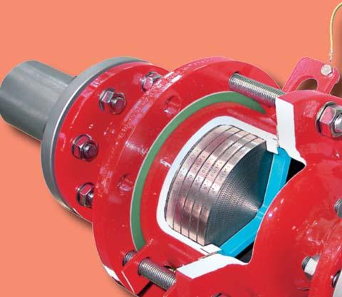


113 PROTEGO Detonation Flame Arresters Volume 4 Volume 4
114 Detonation Flame Arrester Function and description The function of fl ame arresters in the various combustion processes and applications is discussed in Technical Fundamentals ( Vol. 1). In this chapter, PROTEGO s product line of detonation arresters for stable and unstable detonations is presented. PROTEGO detonation fl ame arresters are highly developed safety devices that are used in pipe systems in which detonations can occur. They reliably suppress the effect of a detonation, extinguish the fl ame, and protect non-explosionproof components and vessels. The main component generally is the original PROTEGO fl a- me arrester unit (1), which takes the energy from the detonation and extinguish the fl ame in narrow gaps. The PROTEGO fl ame arrester unit consists of several FLAMEFILTER discs (2) and spacers, fi rmly held in the FLAMEFILTER cage (3). The number of FLAMEFILTER discs and their gap size depend on the devices intended use and on process parameters such as temperature, pressure, vapour group of the handled gases. Special features and advantages The most important distinctive features are the selection criteria: Stable or unstable detonations, dry detonation arresters for installation in gas- or vapour-conducting pipes, or liquid detonation arresters, i.e. fl ame arresters with a liquid barrier for pipes in which liquids are transported. For the parameters of pressure and temperature, special operating conditions beyond standard values may have to be considered. It is important to categorize the products or the components of the mixture into explosion groups according to their MESG to select the suitable fl ame arrester from the various designs for all the explosion groups. The designs differ according to their concentric, eccentric, and 90-degree design. The respective system specifi cation must be considered when choosing the required nominal diameters and types of connection. A heating jacket may be necessary, but not every device can be provided with a heating jacket. There are designs for critical media, special product properties (such as viscosity, density, crystallization, and polymerization), and for unidirectional or bidirectional protection. Preferred applications Protection of PROTEGO fl ame arrester unit All dry detonation fl ame arrester types have a modular design. For larger nominal diameters, energy is withdrawn from the detonation shock wave upon entering the patented shock absorber, the SWGTE (Shock Wave Guide Tube Effect), and other innovative technical solutions, before the detonation reaches the FLAMEFILTER. Dry PROTEGO detonation fl ame arresters are also tested and safe with respect to defl agrations. Equipped with an additional temperature sensor, they are also protected from short-time stabilized burning on the FLAMEFILTER. Piping systems Tanks and vessels in chemical, petrochemical, and pharmaceutical processing plants Loading systems Gas collection systems Exhaust gas combustion systems Flare systems Landfi lls and biogas systems Waste-water treatment plants In close collaboration with scientifi c institutions, PROTEGO has developed safety devices that can be used in any area subject to an explosion hazard and protects against stable and unstable detonations, unidirectional or bidirectional. Corresponding statements of conformity (CE, etc.) have been awarded based on type tests according to ATEX, PED, and other international standards. A wide range of types, designs, nominal diameters and materials are available. In addition, we are able to develop tailor made solutions at our worldwide unique testing facility. All rights and alterations reserved acc. ISO Active data sheet at KA / 4 / 0318 / GB
115 Installation and maintenance PROTEGO detonation fl ame arresters are also tested and protect against defl agrations so that they can be used at any distance from a potential ignition source. However, they are preferably installed as close as possible to the part of the system to be protected. No pipes with a nominal diameter greater than the nominal diameter of the devices shall be connected to detonation arresters. Given the modular design of the PROTEGO fl ame arrester unit, any type of detonation fl ame arrester is extremely easy to service. For servicing reasons, the location of the fl ame arrester must be planned to be very accessible; a hoist must be provided if the fl ame arrester is heavy. Servicing is easy for trained personnel. PROTEGO detonation fl ame arresters are used in areas subject to explosion hazards. Select devices that match the intended use. The manufacturer s certifi cate of conformity provides the boundary conditions for which the device is suitable. The user has to document proper use in accordance with applicable safety guidelines or standards. Selection The possible types are pre-selected from the product line based on the most important process data: Sizing The nominal diameter of the device is determined or checked in the p/v fl ow chart. A safety margin must be provided when the processed fl uid is highly contaminated. Given: Volume fl ow m 3 /h or CFH Given: Max. all. pressure drop p mbar or inch W.C. Desired: Nominal diameter of the detonation fl ame arrester DN Procedure: Intersection of the lines with the volume fl ow and maximum allowable pressure drop lies above or on the desired nominal diameter curve or Given: Volume fl ow m 3 /h or CFH Given: Nominal diameter of pipe DN Desired: Pressure drop p mbar or inch W.C. Procedure: Intersection of the lines with the volume fl ow and nominal diameter curve, horizontal straight line leads to the desired pressure drop Instructions on how to calculate the volumetric fl ow or infl uence of density are found in Vol. 1 Technical Fundamentals. After all steps are complete, the device can be completely specifi ed and requested or ordered. Stable detonations or unstable detonations Lines that conduct dry gas/vapours or liquids Standard or non-standard operating conditions (pressure and temperature) Explosion group of the transported mixture Finally, the following criteria are reviewed and selected: Approvals according to ATEX, USCG, CSA, GOST-R, GL, IMO, etc. Concentric, excentric, or 90-degree design Nominal diameter and type of connection Heating jacket or custom-supplied electrical heat tracing Critical media Unidirectional or bidirectional If no suitable device can be found, please contact us. Special designs and approvals are available. pressure drop p (mbar) airfl ow in thousands of CFH fl ow rate V. (m³/h) pressure drop p inch W.C. Based on this initial selection, the additional details such as materials, coatings, etc. can be requested or defi ned in the type sheet. KA / 4 / 0318 / GB 115
116 Selection Guide PROTEGO Detonation Flame Arrester Catalogue Type Size Design cc = concentric ec = eccentric Explosion Group Approvals = dry type x = liquid type = for non-standartd operating parameter = for critical medium (polimerisation, corrosion, crystallisation) = Heating jacket, Heating coil = unidirectional, x = bidirectional Page ATEX NEC for stable detonation DA-G G ½ - G 2 straigth through, cc IIA, IIB3, IIC D, C, B ATEX x DR/SV G ½ - G ¾ straight through, cc IIA D ATEX DA-E " - 12" straight through, ec IIA, IIB3 D, C ATEX x DA-SB " - 24" straight through, cc IIA, IIB3, IIC D, C, B ATEX x DA-SB-PTFE " - 4" straight through, cc IIA D ATEX x DR/ES G ¼ -G ¾ 90-degree IIA, IIB3, IIC D, C, B ATEX DR/ES " - 8" 90-degree IIA, IIB3 D, C ATEX /x DR/ES series " - 4" 90-degree IIA, IIB3 D, C ATEX /x DR/ES-V ½" - 8" 90-degree IIA, IIB3 D, C ATEX DR/ES-PTFE ½" - 6" 90-degree IIA D ATEX DR/SBW " - 16" straight through, cc IIA, IIB3 D, C ATEX x BR/TS 80 3" 90-degree IIB3, IIB C, B ATEX -IIB -IIB3 All rights and alterations reserved acc. ISO Active data sheet at KA / 4 / 0318 / GB
117 Type Size Design cc = concentric ec = eccentric Explosion Group Approvals = dry type x = liquid type = for non-standartd operating parameter = for critical medium (polimerisation, corrosion, crystallisation) = Heating jacket, Heating coil = unidirectional, x = bidirectional Page ATEX NEC for stable detonation / for liquid detonation LDA-W " - 12" straight through IIA, IIB3 D, C ATEX x LDA-WF(W) " - 10" straight through IIA, IIB3 D, C ATEX x LDA " - 10" vertical IIA, IIB3 D, C ATEX x LDA-F " - 10" vertical IIA, IIB3 D, C ATEX x EF/V " - 10" vertical IIB3 C ATEX x TS/P TS/E TS/W IIA, IIB3, IIC D, C, B ATEX x for unstable detonation DA-UB " - 24" straight through, cc IIA, IIB3 D, C ATEX x DA-CG " - 24" straight through, cc IIA, IIB3 D, C USCG x DR/EU " - 6" 90-degree IIA, IIB2, IIB3 D, C, C ATEX DA-UCG Larger sizes upon request straight through, cc IIA D ATEX USCG x NEW NEU KA / 4 / 0318 / GB 117
 that can be used for all explosion groups, IIA, IIB3 and IIC (NEC Group D, C MESG 0.65 mm and B).")
 and higher temperatures upon request. The device is bidirectional and equipped with a threaded connection.")
118 In-Line Detonation Flame Arrester for stable detonations and deflagrations in a straight through design, bidirectional PROTEGO DA-G SW DN Design with one temperature sensor drawn displaced Design with two temperature sensors Ø b Ø a d dismantling dimension for servicing (temperature sensor) that can be used for all explosion groups, IIA, IIB3 and IIC (NEC Group D, C MESG 0.65 mm and B). The standard design can be used up to an operating temperature of +60 C / 140 F and an absolute operating pressure up to 1.1 bar / 15.9 psi. Devices with special approvals can be obtained for higher pressures (see table 4) and higher temperatures upon request. The device is bidirectional and equipped with a threaded connection. The thread can be executed to international standards. The detonation arrester can be used at any location in the pipe, independently from the location of the ignition source. Type-approved in accordance with the current ATEX Directive and EN ISO as well as other international standards. Special Features and Advantages bidirectional modular design 1 Connection to the protected side (only for type DA-G-T-...) c the individual FLAMEFILTER discs can be quickly removed and installed the individual FLAMEFILTER discs are easy to service and replace different application possibilities use of temperature sensors for G 1½ and G 2 is possible Function and Description The PROTEGO DA-G series is a compact in-line detonation fl ame arrester for installation in pipes with diameters up to 2, and is used, for example, in industrial applications such as gas analyzing lines. Once a detonation enters the fl ame arrester, energy is absorbed from the shock wave, and the fl ame is extinguished in the narrow gaps of the FLAMEFILTER (1). The PROTEGO fl ame arrester unit consists of several FLAME- FILTER discs fi rmly held in a housing. The gap size and number of FLAMEFILTER discs are determined by the operating data and parameters of the mixture fl owing in the line (explosion group, pressure, temperature). To provide an optimum result between the housing size, number of FLAMEFILTER discs and their gap size, a device was developed cost effi cient spare parts Design Types and Specifications There are three different designs available: Basic design of the DA-G in-line detonation fl ame arrester, size ½ to 2 In-line detonation flame arrester with integrated temperature sensor* as additional protection against short burning from one side, size 1½ to 2 In-line detonation flame arrester with two integrated temperature sensors* as additional protection against short time burning from both sides, size 1½ to 2 *Resistance thermometer for device group II, category (1) 2 (GII cat. (1) 2) Flange connection available upon request DA-G- DA-G- T DA-G- TB All rights and alterations reserved acc. ISO Active data sheet at KA / 4 / 0318 / GB
119 Table 1: Dimensions Dimensions in mm / inches, SW = width across fl ats To select the nominal size (DN), please use the fl ow capacity charts on the following pages DN G ½ G ¾ G 1 G 1 ¼ G 1 ½ G 2 a 80 / / / / / / 6.10 b 55 / / / / / / 4.88 c (IIA) 112 / / / / / / 8.07 c (IIB3 and IIC) 135 / / / / / / 8.07 d 400 / / SW 32 / / / / / / 2.95 Table 2: Selection of the explosion group MESG Expl. Gr. (IEC/CEN) Gas Group (NEC) > 0,90 mm IIA D 0,65 mm IIB3 C < 0,50 mm IIC B Special approvals upon request Table 3: Selection of max. operating pressure DN G ½ G ¾ G 1 G 1 ¼ G 1 ½ G 2 Expl. Gr. IIA P max 1.2/ / / / / /15.9 IIB3 P max 1.1/ / / / / /20.3 IIC P max 1.1/ / / / / /23.2 P max = maximum allowable operating pressure in bar / psi (absolute), higher operating pressure upon request Table 4: Specification of max. operating temperature 60 C / 140 F Tmaximum allowable operating temperature in C - Designation higher operating temperatures upon request Table 5: Material selection Design B C Housing Stainless Steel Hastelloy Gasket PTFE PTFE FLAMEFILTER * Stainless Steel Hastelloy Special materials upon request * the FLAMEFILTER is also available in the materials Tantalum, Inconel, Copper, etc. when the listed housing materials are used. Table 6: Type of connection Pipe thread DIN ISO DIN other types of thread upon request KA / 4 / 0318 / GB 119
 Leistung-000337-en * P1.")
 Leistung-000338-en The fl ow capacity charts have been determined with a calibrated and TÜV certifi ed fl ow capacity")

120 In-Line Detonation Flame Arrester Flow Capacity Charts PROTEGO DA-G airfl ow in thousands of CFH pressure drop p (mbar) DA-G-IIA-P1.1 pressure drop p inch W.C. fl ow rate V. (m³/h) Leistung en * P1.4 * * airfl ow in thousands of CFH pressure drop p (mbar) DA-G-IIB3-P1.1 pressure drop p inch W.C. fl ow rate V. (m³/h) Leistung en The fl ow capacity charts have been determined with a calibrated and TÜV certifi ed fl ow capacity test rig. Volume fl ow V. in (m³/h) and CFH refer to the standard reference conditions of air ISO 6358 (20 C, 1bar). Conversion to other densities and temperatures refer to Vol. 1: Technical Fundamentals. All rights and alterations reserved acc. ISO Active data sheet at KA / 4 / 0318 / GB


121 In-Line Detonation Flame Arrester Flow Capacity Chart PROTEGO DA-G * P1.6 * * airfl ow in thousands of CFH pressure drop p (mbar) DA-G-IIC-P1.1 pressure drop p inch W.C. fl ow rate V. (m³/h) Leistung en KA / 4 / 0318 / GB 121
 DN Design with one temperature sensor Function and Description 1 The PROTEGO DA-E series of detonation arresters is distinguished by its eccentric housing shape.")
122 Eccentric In-Line Detonation Flame Arrester for stable detonations and deflagrations in a straight through design, bidirectional PROTEGO DA-E d dismantling dimension for servicing (temperature sensor) DN Design with one temperature sensor Function and Description 1 The PROTEGO DA-E series of detonation arresters is distinguished by its eccentric housing shape. When condensate accumulates within the PROTEGO fl ame arrester unit, the design enables the liquid to drain without collecting large amounts in the housing. The eccentric design of the device has decisive advantages in comparison to the classic fl ame arresters when pipes are installed close to ground level. The detonation arrester is symmetrical and offers bidirectional fl ame arresting. The arrester essentially consists of two housing parts (1) and the PROTEGO fl ame arrester unit (2) in the center. The PROTEGO fl ame arrester unit consists of several FLAMEFILTER discs (3) and spacers fi rmly held in a FLAMEFILTER cage. The number of FLAMEFILTER discs and their gap size depends on the arrester s conditions of use. By indicating the operating parameters such as temperature, pressure and explosion group and the composition of the fl uid, the optimum detonation arrester 2 a 3 Connection to the protected side (only for type DA-E-T-...) Design with two temperature sensors b DN Ø c can be selected. The PROTEGO DA-E series of fl ame arresters is available for explosion groups IIA to IIB3 (NEC Group D to C MESG 0.65 mm). The standard design can be used up to an operating temperature of +60 C / 140 F and an absolute operating pressure acc. to table 3. Devices with special approval can be obtained for higher pressures and higher temperatures upon request. Type-approved in accordance with the current ATEX Directive and EN ISO as well as other international standards. Special Features and Advantages eccentric design prevents the collection of condensate the modular design enables each individual FLAMEFILTER discs to be replaced easy maintenance with quick removal and installation of FLAMEFILTER discs eccentric design allows installation in close to ground level bidirectional operation as well as any fl ow direction and installation position protects from defl agration and stable detonation installation of temperature sensors possible cost effi cient spare parts Design Types and Specifications There are three different designs available: Basic design of the detonation arrester In-line detonation flame arrester with integrated temperature sensor* as additional protection against short time burning of one side Detonation arrester with two integrated temperature sensors* as additional protection against short time burning from both sides Additional special arresters upon request *Resistance thermometer for device group II, category (1) 2 (GII cat. (1) 2) DA-E- DA-E- T DA-E- TB All rights and alterations reserved acc. ISO Active data sheet at KA / 4 / 0318 / GB
123 Stabilized FLAMEFILTER Discs (Flyer pdf) Table 1: Dimensions To select the nominal size (DN), please use the fl ow capacity charts on the following pages Expl. Gr. IIA IIB3 DN a a b c d 25 1" 304/315* / 11.97/12.4* 304/ / / / ¼" 304/315* / 11.97/12.4* 304/ / / / ½" 320/ / / / / " 325/ / / / / ½" 370/ / / / / " 375/ / / / / * for IIA-P2.0 Table 2: Selection of the explosion group MESG Expl. Gr. (IEC/CEN) Gas Group (NEC) > 0,90 mm IIA D 0,65 mm IIB3 C 100 4" 380/ / / / / " 481/ / / / / " 487/ / / / / Dimensions in mm / inches 200 8" 510/ / / / / " 540/ / / / / Special approvals upon request " 560/ / / / / Table 3: Selection of max. operating pressure Expl. Gr. 25 DN 1" 2.0 / IIA P max / IIB3 P max ¼" 2.0 / / ½" 1.2 / / " 1.2 / / ½" P max = maximum allowable operating pressure in bar / psi (absolute), higher operating pressure upon request 1.2 / / " 1.2 / / " 1.2 / / " 1.2 / / " 1.2 / / " 1.2 / / " 1.2 / / " 1.2 / / 17.4 Table 4: Specification of max. operating temperature 60 C / 140 F Tmaximum allowable operating temperature in C - Designation higher operating temperatures upon request Table 5: Material selection for housing Design B C D Housing Steel Stainless Steel Hastelloy Gasket PTFE PTFE PTFE Flame arrester unit A, C C D Special materials upon request Table 6: Material combinations of the flame arrester unit Design A C D FLAMEFILTER cage Steel Stainless Steel Hastelloy FLAMEFILTER * Stainless Steel Stainless Steel Hastelloy Spacer Stainless Steel Stainless Steel Hastelloy Special materials upon request Table 7: Flange connection type EN ; Form B1 ASME B16.5; 150 lbs RFSF The housing is also available in carbon steel with an ECTFE coating. *the FLAMEFILTER are also available in the materials Tantalum, Inconel, Copper, etc. when the listed housing and cage materials are used. other types upon request KA / 4 / 0318 / GB 123
 Leistung-000236-en 1943-L * P1.1 * * airfl ow in thousands of CFH DA-E-IIB3-P1.2 pressure drop p (mbar) pressure drop p inch W.C. fl ow rate V.")
 and CFH refer to the standard reference conditions of air ISO 6358 (20 C, 1bar). Conversion to other densities and temperatures refer to Vol. 1: Technical Fundamentals.")
124 Eccentric In-Line Detonation Flame Arrester Flow Capacity Charts PROTEGO DA-E * P1.3 * * airfl ow in thousands of CFH DA-E-IIA-P1.2 -IIA-P1. pressure drop p (mbar) pressure drop p inch W.C. fl ow rate V. (m³/h) Leistung en 1943-L * P1.1 * * airfl ow in thousands of CFH DA-E-IIB3-P1.2 pressure drop p (mbar) pressure drop p inch W.C. fl ow rate V. (m³/h) Leistung en The fl ow capacity charts have been determined with a calibrated and TÜV certifi ed fl ow capacity test rig. Volume fl ow V. in (m³/h) and CFH refer to the standard reference conditions of air ISO 6358 (20 C, 1bar). Conversion to other densities and temperatures refer to Vol. 1: Technical Fundamentals. All rights and alterations reserved acc. ISO Active data sheet at KA / 4 / 0318 / GB
125 Notes: 125
126 In-Line Detonation Flame Arrester for stable detonations and deflagrations in a straight through design with shock tube, bidirectional PROTEGO DA-SB Ø a 1 DN Design with one temperature sensor 2 3 Connection to the protected side (only for type DA-SB-T-...) Function and Description The in-line detonation fl ame arresters type PROTEGO DA-SB are the newest generation of fl ame arresters. On the basis of fl uid dynamic, explosion dynamics calculation and decades of experience from fi eld tests, a product line was developed that offers minimum pressure loss and maximum safety. The fl ame arrester uses the Shock Wave Guide Tube Effect (SWGTE) to separate the fl ame front and shock wave. The result is an in-line detonation arrester without a classic shock absorber; in addition the use of FLAMEFILTER discs is minimized. The devices are symmetrical and offer bidirectional fl ame arresting for defl agrations and stable detonations. The arrester essentially consists of two housing parts with an integrated shock tube (1) and the PROTEGO fl ame arrester unit (2) in the center. The PROTEGO fl ame arrester unit is modular and consists of several FLAMEFILTER discs (3) and spacers fi rmly held in a FLAMEFILTER cage. The number of FLAME- FILTER discs and their gap size depends on the arrester s conditions of use. By indicating the operating parameters such as temperature, pressure and explosion group, and the composition of the fl uid, the optimum detonation arrester can be selected from a series of approved devices. The PROTEGO DA-SB fl ame arresters are available for all explosion groups. The standard design can be used up to an operating temperature of +60 C / 140 F and an absolute operating pressure up to 1.1 bar / 15.9 psi. Numerous devices with special approval can be obtained for higher presssures (see table 3) and higher temperatures. b Design with two temperature sensors DN NG c dismantling dimension for servicing (temperature sensor) Type-approved in accordance with the current ATEX Directive and EN ISO as well as other international standards. Special Features and Advantages optimized performance from the patented Shock Wave Guide Tube Effect (SWGTE) less number of FLAMEFILTER discs from the use of the patented shock tube (SWGTE) modular fl ame arrester unit enables each individual FLAMEFILTER discs to be replaced and cleaned different series allow increase of FLAMEFILTER size for given flange connection resulting in lower pressure drop across the device service-friendly design expanded application range for higher operating temperatures and pressures bidirectional operation as well as any direction of flow and installation position installation of temperature sensors are possible minimum pressure loss and associated low operating and life-cycle cost cost efficient spare parts use of stabilized FLAMEFILTER discs is possible use of PROTEGO Flame Arrester Unit in unique NEW maintenance friendly design reduces service cost Design Types and Specifications There are four different designs available: Basic in-line detonation fl ame arrester In-line detonation flame arrester with integrated temperature sensor* as additional protection against short time burning from one side In-line detonation flame arrester with two integrated temperature sensors* for additional protection against short time burning from both sides In-line detonation flame arrester with heating jacket Additional special fl ame arresters upon request *Resistance thermometer for device group II, category (1) 2 (GII cat. (1) 2) DA-SB - - DA-SB - T - DA-SB- TB - DA-SB - H - All rights and alterations reserved acc. ISO Active data sheet at KA / 4 / 0318 / GB
127 Stabilized FLAMEFILTER Discs (Flyer pdf) New PROTEGO Flame Arrester Unit unique maintenance friendly design (Flyer pdf) Table 1: Dimensions Dimensions in mm / inches To select nominal width/nominal size (NG/DN) - combination, Additional nominal width/nominal size (NG/DN) - combinations please use the fl ow capacity charts on the following pages for improved fl ow capacity upon request standard (special sizes up to NG 2000/80, DN 1000/40 available) b NG DN a IIA-P1,1 IIA-P1,4-X3 IIB3-P1,1 IIB3-P1,4-X3 IIC-P1,1 c 150 6" / / / / / / / " 65, 80 2 ½, / / / / / / / * dimension b only for P1.4 / 20.3 ** dimension b only for P1.2 / 17.4 *** EN " / / / / / / / " / / / / / / / " / / / / / / / " / / 31.50* 800 / / / / / " / / 39.37* 1000 / / / / 39.37*** 720 / " / / / / / / 47.24*** 770 / " / / / / / / 55.12*** 820 / " / / / / " / / / / " / / 86.61** 1250 / Table 2: Selection of the explosion group MESG Expl. Gr. (IEC/CEN) Gas Group (NEC) > 0,90 mm IIA D 0,65 mm IIB3 C < 0,50 mm IIC B Special approvals upon request Table 3: Selection of max. operating pressure Expl. Gr. NG DN / IIA P max / IIB3 P max / IIC P max , 80 2 ½, / / / / / / / / / / / / / / / / / / * / / / * / / / * 15.9 P max = maximum allowable operating pressure in bar / psi absolut, higher operating pressure upon request in-between size up to P max upon request * capacity charts upon request / / / / / 17.4 KA / 4 / 0318 / GB 127
128 In-Line Detonation Flame Arrester for stable detonations and deflagrations in a straight through design with shock tube, bidirectional PROTEGO DA-SB Table 4: Specification of max. operating temperature 60 C / 140 F 200 C / 392 F Tmaximum allowable operating temperature in C higher operating temperatures upon request - X3 Designation Table 5: Material selection for housing Design A B C Housing Heating jacket (DA-SB-(T)-H-...) Steel Steel Stainless Steel Stainless Steel Gasket PTFE PTFE PTFE Flame arrester unit A, B B, C, D D Special materials upon request Hastelloy Stainless Steel The housing is also available in Steel with ECTFE coating. Table 6: Material combinations of the flame arrester unit Design A B C D FLAMEFILTER cage Steel Stainless Steel Stainless Steel Hastelloy FLAMEFILTER * Stainless Steel Stainless Steel Hastelloy Hastelloy Spacer Stainless Steel Stainless Steel Hastelloy Hastelloy Special materials upon request *the FLAMEFILTER are also available in the materials Tantalum, Inconel, Copper, etc. when the listed housing and cage materials are used. Table 7: Flange connection type EN ; Form B1 ASME B16.5; 150 lbs RFSF other types upon request All rights and alterations reserved acc. ISO Active data sheet at KA / 4 / 0318 / GB
 Leistung-000324-en NG / DN pressure drop p inch W.C. X3 maximum allowable operating temperature 200 C airfl ow in thousands of CFH pressure drop p (mbar) DA-SB-IIA-P1.")
129 In-Line Detonation Flame Arrester Flow Capacity Charts PROTEGO DA-SB * * ** * P1.4 ** P1.2 NG / DN pressure drop p (mbar) airfl ow in thousands of CFH DA-SB-IIA-P1.1 fl ow rate V. (m³/h) Leistung en NG / DN pressure drop p inch W.C. X3 maximum allowable operating temperature 200 C airfl ow in thousands of CFH pressure drop p (mbar) DA-SB-IIA-P1.4-X3 pressure drop p inch W.C. fl ow rate V. (m³/h) Leistung en The fl ow capacity charts have been determined with a calibrated and TÜV certifi ed fl ow capacity test rig. Volume fl ow V. in (m³/h) and CFH refer to the standard reference conditions of air ISO 6358 (20 C, 1bar). Conversion to other densities and temperatures refer to Vol. 1: Technical Fundamentals. KA / 4 / 0318 / GB 129
 Leistung-000332-en NG / DN pressure drop p inch W.C. X3 maximum allowable operating temperature 200 C airfl ow in thousands of CFH DA-SB-IIB3-P1.4-X3 pressure drop p inch W.C. fl ow rate V.")
130 In-Line Detonation Flame Arrester Flow Capacity Charts PROTEGO DA-SB NG / DN pressure drop p (mbar) pressure drop p (mbar) airfl ow in thousands of CFH DA-SB-IIB3-P1.1 fl ow rate V. (m³/h) Leistung en NG / DN pressure drop p inch W.C. X3 maximum allowable operating temperature 200 C airfl ow in thousands of CFH DA-SB-IIB3-P1.4-X3 pressure drop p inch W.C. fl ow rate V. (m³/h) Leistung en The fl ow capacity charts have been determined with a calibrated and TÜV certifi ed fl ow capacity test rig. Volume fl ow V. in (m³/h) and CFH refer to the standard reference conditions of air ISO 6358 (20 C, 1bar). Conversion to other densities and temperatures refer to Vol. 1: Technical Fundamentals. All rights and alterations reserved acc. ISO Active data sheet at KA / 4 / 0318 / GB
131 NG / DN pressure drop p (mbar) airfl ow in thousands of CFH DA-SB-IIC-P1.1 pressure drop p inch W.C. fl ow rate V. (m³/h) Leistung en KA / 4 / 0318 / GB 131
 whose gap size and number is determined by the operating parameters of the processed fl uid (explosion group, pressure,")
132 In-Line Detonation Flame Arrester for stable detonations and deflagrations in right angle design, unidirectional PROTEGO DR/ES a DN The PROTEGO fl ame arrester unit (2) consists of several FLAMEFILTER discs and spacers (for explosion group IIC - NEC group B) whose gap size and number is determined by the operating parameters of the processed fl uid (explosion group, pressure, temperature). This device is available for explosion groups IIB3 and IIC (NEC group C MESG 0.65 mm and B). d c This in-line detonation fl ame arrester functions unidirectional and is equipped with a threaded connection. The thread can be adapted to international standards. The standard design is approved at an operating temperature up to +60 C / 140 F and an absolute operating pressure acc. to table 3. Devices with special approvals can be obtained for higher pressures and higher temperatures upon request. Type-approved in accordance with the current ATEX Directive and EN ISO as well as other international standards. only for design IIB3 Function and Description DN Ø e Connection to the protected side The PROTEGO DR/ES series in-line detonation fl ame arrester with connection size up to ¾ is ideal for installation in small pipes and to protect equipment such as gas analyzers. The device protects against defl agrations and stable detonations. It can be installed anywhere in the pipe no matter what the distance is from the potential ignition source. The small and compact fl ame arrester has a right angle design. b Special Features and Advantages compact design minimum number of FLAMEFILTER discs due to shock absorber technology and optimal geometry Design for IIB3: the device can be serviced without disconnecting the pipe the individual FLAMEFILTER can be quickly removed and installed provides protection from defl agration and stable detonation through right angle design no pipe elbows are needed works for nearly any fl ammable gas and gas mixture low life-cycle cost cost effi cient spare parts Once a detonation enters the fl ame arrester, energy is absorbed from the detonation shock wave by diversion mainly through the shock absorber (1) before the fl ame is extinguished in the narrow gaps of the FLAMEFILTER (3). All rights and alterations reserved acc. ISO Active data sheet at KA / 4 / 0318 / GB
133 Table 1: Dimensions Dimensions in mm / inches To select the nominal size (DN), please use the fl ow capacity charts on the following pages DN G ¼ G ½ G¾ a 48 / / / 3.15 b 35 / / / 1.85 c 70 / / / 3.43 d 108 / / / 5.31 e 34 / / / 2.36 Table 2: Selection of the explosion group MESG Expl. Gr. (IEC/CEN) Gas Group (NEC) 0,65 mm IIB3 C < 0,50 mm IIC B Special approvals upon request Table 3: Selection of max. operating pressure DN G¼ G ½ G ¾ P max = maximum allowable operating pressure IIB3 P max 1.2 / / / 17.4 in bar / psi (absolute), higher operating pressure upon request IIC P max 1.1 / / / 15.9 Expl. Gr. IIB3 covers Expl. Gr. IIA Expl. Gr. Table 4: Specification of max. operating temperature 60 C / 140 F Tmaximum allowable operating temperature in C - Designation higher operating temperatures upon request Table 5: Material selection for housing Design B C D Housing Steel Stainless Steel Hastelloy Cover with shock absorber* Steel Stainless Steel Hastelloy Gasket PTFE PTFE PTFE Flame arrester unit A A B Special materials upon request G ¼ only comes in design C and D * G ¼ without shock absorber Table 6: Material combinations of the flame arrester unit Design A B * the FLAMEFILTER are also available in the materials FLAMEFILTER * Stainless Steel Hastelloy Tantalum, Inconel, Copper, etc. when the listed Spacer Stainless Steel Hastelloy housing and cage materials are used. Special materials upon request Table 7: Type of connection Pipe thread DIN ISO DIN other types of thread upon request KA / 4 / 0318 / GB 133
134 In-Line Detonation Flame Arrester Flow Capacity Charts PROTEGO DR/ES airfl ow in thousands of CFH pressure drop p (mbar) DR/ES-IIB3-P1.2 pressure drop p - inch W.C. fl ow rate V. (m³/h) Leistung en airfl ow in thousands of CFH pressure drop p (mbar) DR/ES-IIC-P1.1 pressure drop p - inch W.C. fl ow rate V. (m³/h) Leistung en The fl ow capacity charts have been determined with a calibrated and TÜV certifi ed fl ow capacity test rig. Volume fl ow V. in (m³/h) and CFH refer to the standard reference conditions of air ISO 6358 (20 C, 1bar). Conversion to other densities and temperatures refer to Vol. 1: Technical Fundamentals. All rights and alterations reserved acc. ISO Active data sheet at KA / 4 / 0318 / GB
135 Notes: 135
 The standard design is approved at an operating")
136 In-Line Detonation Flame Arrester for stable detonations and deflagrations in right angle design with shock absorber, unidirectional PROTEGO DR/ES Ø d DN Design with installed temperature sensor a Connection to the protected side DN b c c1 dismantling dimension for servicing e dismantling dimension for servicing (temperature sensor) The standard design is approved at an operating temperature up to +60 C / 140 F and an absolute operating pressure up to 1.2 bar / 17.4 psi. Devices with special approvals can be obtained for higher pressures and higher temperatures upon request. Type-approved in accordance with the current ATEX Directive and EN ISO as well as other international standards. Special Features and Advantages minimum number of FLAMEFILTER discs due to the effective shock absorber quick removal and installation of the complete PROTEGO fl ame arrester unit and FLAMEFILTER discs in the cage due to modular design the FLAMEFILTER discs can be individually replaced the right angle design saves pipe elbows extended application range for higher operating temperatures and pressures minimum pressure loss and hence low operating and lifecycle cost cost effi cient spare parts Design Types and Specifications Function and Description The PROTEGO DR/ES in-line detonation fl ame arrester has been used for decades in industrial plant construction because its right angle design offers advantages towards maintenance and costs in comparison to most straight designs. Once a detonation enters the device, energy is absorbed from the detonation shock wave by the integrated shock absorber (1) before the fl ame is extinguished in the narrow gaps of the FLAMEFILTER (3). The PROTEGO fl ame arrester unit (2) consists of several FLAMEFILTER discs and spacers fi rmly held in the FLAME- FILTER cage (4). The gap size and number of FLAMEFILTER discs are determined by the operating data of the mixture fl owing in the line (explosion group, pressure, temperature). This device is approved for explosion groups from IIA to IIB3 (NEC group D to C MESG 0.65 mm). There are four different designs available: Basic in-line detonation fl ame arrester In-line detonation flame arrester with integrated temperature sensor* as additional protection against short time burning In-line detonation flame arrester with heating jacket In-line detonation flame arrester with integrated temperature sensor* against short time burning and heating jacket *Resistance thermometer for device group II, category (1) 2 (GII cat. (1) 2) DR/ES- - DR/ES- T - DR/ES- H - DR/ES- H - T All rights and alterations reserved acc. ISO Active data sheet at KA / 4 / 0318 / GB
137 Stabilized FLAMEFILTER Discs (Flyer pdf) Table 1: Dimensions Dimensions in mm / inches To select the nominal size (DN), please use the fl ow capacity charts on the following pages DN 25 / 1" 32 / 1 ¼" 40 / 1 ½" 50 / 2" 65 / 2 ½" 80 / 3" 100 / 4" 125 / 5" 150 / 6" 200 / 8 a 125/ / / / / / / / / /16.73 b 140/ / / / / / / / / /19.88 c 210/ / / / / / / / / /31.89 c1 285/ / / / / / / / / /48.43 d 150/ / / / / / / / / /24.41 e 495/ / / / / / / / / /56.50 Table 2: Selection of the explosion group MESG Expl. Gr. (IEC/CEN) Gas Group (NEC) > 0,90 mm IIA D 0,65 mm IIB3 C Special approvals upon request Table 3: Selection of max. operating pressure DN 25 / 1" 32 / 1 ¼" 40 / 1 ½" 50 / 2" 65 / 2 ½" 80 / 3" 100 / 4" 125 / 5" 150 / 6" 200 / 8 Expl. Gr. IIA P max 4.0/ / / / / / / / / /17.4 IIB3 P max 3.0/ / / / / / / / / /15.9 P max = maximum allowable operating pressure in bar / psi (absolute), higher operating pressure upon request Table 4: Specification of max. operating temperature 60 C / 140 F Tmaximum allowable operating temperature in C - Designation higher operating temperatures upon request Table 5: Material selection for housing Design B C D Housing Heating jacket (DR/ES-H-(T)-...) Steel Steel Stainless Steel Stainless Steel Hastelloy Stainless Steel Cover with shock absorber Steel Stainless Steel Hastelloy O-Ring FPM* PTFE PTFE Flame arrester unit A C, D E * for devices exposed to elevated temperatures above 150 C / 302 F, gaskets made of PTFE.The housing and cover with the shock absorber can also be delivered in steel with an ECTFE coating. Special materials upon request Table 6: Material combinations of the flame arrester unit Design A C D E FLAMEFILTER cage Steel Stainless Steel Stainless Steel Hastelloy FLAMEFILTER * Stainless Steel Stainless Steel Hastelloy Hastelloy Spacer Stainless Steel Stainless Steel Hastelloy Hastelloy Special materials upon request * the FLAMEFILTER are also available in the materials Tantalum, Inconel, Copper, etc. when the listed housing and cage materials are used. Table 7: Flange connection type EN ; Form B1 ASME B16.5; 150 lbs RFSF other types upon request KA / 4 / 0318 / GB 137
138 In-Line Detonation Flame Arrester Flow Capacity Charts PROTEGO DR/ES airfl ow in thousands of CFH pressure drop p (mbar) DR/ES-IIA-P1.2 pressure drop p - inch W.C. fl ow rate V. (m³/h) Leistung en airfl ow in thousands of CFH pressure drop p (mbar) DR/ES-IIA-P1.6 pressure drop p - inch W.C. fl ow rate V. (m³/h) Leistung en The fl ow capacity charts have been determined with a calibrated and TÜV certifi ed fl ow capacity test rig. Volume fl ow V. in (m³/h) and CFH refer to the standard reference conditions of air ISO 6358 (20 C, 1bar). Conversion to other densities and temperatures refer to Vol. 1: Technical Fundamentals. All rights and alterations reserved acc. ISO Active data sheet at KA / 4 / 0318 / GB
139 In-Line Detonation Flame Arrester Flow Capacity Charts PROTEGO DR/ES airfl ow in thousands of CFH pressure drop p (mbar) DR/ES-IIB3-P1.2 pressure drop p - inch W.C. fl ow rate V. (m³/h) Leistung en * DN 25 - DN 80; P1.6 DN 100; P1.5 DN 125, DN 150; P1.4 DN 200; P1.1 airfl ow in thousands of CFH pressure drop p (mbar) DR/ES-IIB3-P* pressure drop p - inch W.C. fl ow rate V. (m³/h) Leistung en KA / 4 / 0318 / GB 139
140 In-Line Detonation Flame Arrester Flow Capacity Charts (liquid) PROTEGO DR/ES fl ow rate (liquid) in thousands of CFH pressure drop p (mbar) DR/ES-IIA-P1.6 (liquid) pressure drop p - inch W.C. fl ow rate V. (m³/h) (liquid) Leistung en * DN 25 - DN 80; P1.6 DN 100; P1.5 DN 125, DN 150; P1.4 DN 200; P1.1 fl ow rate (liquid) in thousands of CFH pressure drop p (mbar) DR/ES-IIB3-P* (liquid) pressure drop p - inch W.C. fl ow rate V. (m³/h) (liquid) Leistung en Conversion: V. = V. liquid water * p p p water liquid The volume fl ow V. in m³/h was determined with water according to DIN EN at a temperature T n = 15 C and an atmospheric pressure p n = 1,013 bar, kinematic viscosity v = 10-6 m²/s All rights and alterations reserved acc. ISO Active data sheet at KA / 4 / 0318 / GB
141 Notes: 141
. The fl ame suppression is guaranteed independent of the valve pallet position.")
.")
142 In-Line Detonation Flame Arrester with integrated pressure relief valve, for stable detonations and deflagrations in right angle design with shock absorber, unidirectional PROTEGO DR/ES-V Ø d absorber, before the fl ame is extinguished in the narrow gaps of the FLAMEFILTER (3). The fl ame suppression is guaranteed independent of the valve pallet position DN b c c1 dismantling dimension for servicing The PROTEGO fl ame arrester unit (2) consists of several FLAMEFILTER discs and spacers fi rmly held in the FLAME- FILTER cage (4). The gap size and number of FLAMEFILTER discs are determined by the operating data parameters of the mixture fl owing in the line (explosion group, pressure, temperature). This device is available for explosion groups from IIA to IIB3 (NEC group D to C MESG 0.65 mm). The standard design is approved at an operating temperature up to +60 C / 140 F and absolute operating pressure up to 1.2 bar / 17.4 psi. Devices with special approvals can be obtained for higher pressures and higher temperatures upon request. Type-approved in accordance with the current ATEX Directive and EN ISO as well as other international standards. DN Connection to the protected side Set pressure: from +2.0 mbar from +0.8 inch W.C. Higher or lower settings upon request Function and Description up to +35 mbar up to +14 inch W.C. PROTEGO DR/ES-V series uniquely combines the function of a in-line detonation fl ame arrester with the function of a pressure relief valve in one device. The device protects against defl agration and stable detonation. The weight-loaded pallet type valve (5) integrated in the shock absorber (1) of the in-line detonation fl ame arrester is designed as pressure relief valve. The set pressure of the valve is adjusted in the factory and can range from 2 to 35 mbar (0.8 to 14 inch W.C.). After the pressure increases 40% from its set pressure, the valve completely opens to yield the maximum volumetric fl ow. If installed in vent headers comected to storage tanks, the valve pallet works as check valve. This means that the product can not fl ow back from the suction line into the tank. Although several functions are integrated in a single housing, the device is extremely easy to service, which is primarily due to the classic right angle design. Once a detonation enters the fl ame arrester, energy is absorbed from the detonation shock wave by the integrated shock a Special Features and Advantages integration of in-line detonation fl ame arrester and pressure relief valve in one device excellent tightness of the valve applicable as a detonation-proof check valve in suction lines of storage tanks optimum for use as an overfl ow valve in venting and recovering vapour lines minimum number of FLAMEFILTER discs due to the effective shock absorber quick removal and installation of the complete PROTEGO fl ame arrester unit and the individual FLAMEFILTER discs in the cage provides protection from defl agration and stable detonations extended application range for higher operating temperatures and pressures cost effi cient spare parts Design Types and Specifications There are two different designs available: Basic version of the detonation arrester with check valve Detonation arrester with check valve and heating jacket Table 1: Dimensions To select the nominal size (DN), please use the fl ow capacity charts on the following pages DR/ES- V - DR/ES- V - H Dimensions in mm / inches DN 25 / 1 / 32 / 1 ¼" 40 / 1 ½" 50 / 2" 65 / 2 ½" 80 / 3" 100 / 4" 125 / 5" 150 / 6" 200 / 8" a 125 / / / / / / / / / b 140 / / / / / / / / / c 237 / / / / / / / / / c1 345 / / / / / / / / / d 149 / / / / / / / / / All rights and alterations reserved acc. ISO Active data sheet at KA / 4 / 0318 / GB
143 Stabilized FLAMEFILTER Discs (Flyer pdf) Table 2: Selection of the explosion group MESG Expl. Gr. (IEC/CEN) Gas Group (NEC) > 0,90 mm IIA D 0,65 mm IIB3 C Special approvals upon request Table 3: Selection of max. operating pressure Expl. Gr. DN 25 / 1 32 / 1 ¼" 40 / 1 ½" 50 / 2" 65 / 2 ½" 80 / 3" 100 / 4" 125 / 5" 150 / 6" 200 / 8 IIA P max 4.0/ / / / / / / / / /17.4 IIB3 P max 3.0/ / / / / / / / / /15.9 P max = maximum allowable operating pressure in bar / psi (absolute), higher operating pressure upon request Table 4: Specification of max. operating temperature 60 C / 140 F Tmaximum allowable operating temperature in C - Designation higher operating temperatures upon request Table 5: Material selection for housing Design B C D Design Heating jacket (DR/ES-V-H-...) Steel Steel Stainless Steel Stainless Steel Hastelloy Stainless Steel Cover with shock absorber Steel Stainless Steel Hastelloy Gaskets PTFE PTFE PTFE Valve seat Stainless Steel Stainless Steel Stainless Steel Flame arrester unit A C, D E Special materials upon request The housing and the cover with shock absorber can also be delivered in steel with an ECTFE coating. Table 6: Material combinations of the flame arrester unit Design A C D E * the FLAMEFILTER are also FLAMEFILTER cage Steel Stainless Steel Stainless Steel Hastelloy available in the materials Tantalum, Inconel, Copper, etc. when FLAMEFILTER * Stainless Steel Stainless Steel Hastelloy Hastelloy the listed housing and cage Spacer Stainless Steel Stainless Steel Hastelloy Hastelloy materials are used. Special materials upon request Table 7: Material selection for valve pallet Design A B C Pressure range I II III Set pressure (mbar) [inch W.C.] +2.0 up to up to +1.4 >+3.5 up to +14 >+1.4 up to +5.6 >+14 up to 35 >+5.6 up to 14 Valve pallet Aluminium Stainless Steel Stainless Steel Sealing FEP FEP Metal to Metal Table 8: Flange connection type EN ; Form B1 ASME B16.5; 150 lbs RFSF other types upon request KA / 4 / 0318 / GB 143
 Leistung-000261-en airfl ow in thousands of CFH pressure P (mbar) DR/ES-V-IIA-P1.6 40 % overpressure pressure P - inch W.C. fl ow rate V.")
144 In-Line Detonation Flame Arrester Flow Capacity Charts PROTEGO DR/ES-V airfl ow in thousands of CFH DR/ES-V-IIA-P % overpressure pressure P (mbar) pressure P - inch W.C. fl ow rate V. (m³/h) Leistung en airfl ow in thousands of CFH pressure P (mbar) DR/ES-V-IIA-P % overpressure pressure P - inch W.C. fl ow rate V. (m³/h) Leistung en Remark set pressure = opening pressure resp. tank design pressure 1,4 Set pressure = the valve starts to open Opening pressure = set pressure plus overpressure Overpressure = pressure increase over the set pressure The fl ow capacity charts have been determined with a calibrated and TÜV certifi ed fl ow capacity test rig. Volume fl ow V. in (m³/h) and CFH refer to the standard reference conditions of air ISO 6358 (20 C, 1bar). Conversion to other densities and temperatures refer to Vol. 1: Technical Fundamentals. All rights and alterations reserved acc. ISO Active data sheet at KA / 4 / 0318 / GB
145 In-Line Detonation Flame Arrester Flow Capacity Charts PROTEGO DR/ES-V airfl ow in thousands of CFH DR/ES-V-IIB3-P % overpressure pressure (mbar) pressure - inch W.C. fl ow rate V. (m³/h) Leistung en * DN 25 - DN 80; P1.6 DN 100; P1.5 DN 125, DN 150; P1.4 DN 200; P1.1 airfl ow in thousands of CFH DR/ES-V-IIB3-P* 40 % overpressure pressure (mbar) pressure - inch W.C. fl ow rate V. (m³/h) Leistung en KA / 4 / 0318 / GB 145


146 In-Line Liquid Detonation Flame Arrester for filling lines - external installation PROTEGO LDA-W a Ø d When a highly accelerated pipe defl agration or detonation occurs, the combustion pressure and fl ame propagation speed is fi rst substantially reduced by the construction and converted into a low-energy defl agration that is then stopped by the remaining immersion liquid. DN DN c The application range for the device is a product vapour/ air mixture temperature up to +60 C / 140 F and an absolute pressure up to 1.1 bar / 15.9 psi. This covers all of the possible operating conditions of empty lines for fl ammable liquids. The liquid detonation arrester is designed for pressures up to 10 bar / 145 psi and therefore resists explosion pressure offering protection for almost all fl ammable liquids. The device is approved for explosion groups IIA to IIB3 (NEC group D to C MESG 0.65 mm). Special designs with a cleaning cover for highly viscous and contaminated liquids can be provided. b Type-approved in accordance with the current ATEX Directive and EN ISO as well as other international standards. Special Features and Advantages the device is easily accessible since it is mounted on the containers outside Tank connection / protected side Function and Description drawn displaced The PROTEGO LDA-W liquid detonation fl ame arrester was developed for storage container fi lling lines that are not continuously fi lled with product and sometimes contain a combustible mixture. The device is installed outside of the container in the fi lling line. If the explosive atmosphere is ignited, the device prevents the combustion from traveling into the tank. The PROTEGO LDA-W series of liquid detonation fl ame arresters functions according to the siphon principle in which the liquid product serves as a barrier against fl ame propagation. minimum risk of soiling low pressure loss provides protection from defl agrations and stable detonations useful for nearly all fl ammable liquids meets TRbF* requirements maintenance friendly design also useable as strainer *TRbF = technical regulations for flammable liquids Table 1: Dimensions To select the nominal size (DN), please use the fl ow capacity chart on the following pages DN a b c d " 1 ¼" 250 / / / / / / / / ½" 350 / / / / " 2 ½" 350 / / / / / / / / " 4" 450 / / / / / / / / " 600 / / / / " 600 / / / / Dimensions in mm / inches 200 8" 700 / / / / " 850 / / / / " 1000 / / / / All rights and alterations reserved acc. ISO Active data sheet at KA / 4 / 0318 / GB

147 Table 2: Selection of the explosion group MESG Expl. Gr. (IEC/CEN) Gas Group (NEC) > 0,90 mm IIA D 0,65 mm IIB3 C Special approvals upon request Table 3: Specification of max. operating temperature 60 C / 140 F Tmaximum allowable operating temperature in C - Designation Table 4: Material selection for housing Design A B C Housing Steel Stainless Steel Hastelloy Gasket PTFE PTFE PTFE Table 5: Flange connection type EN ; Form B1 ASME B16.5; 150 lbs RFSF higher operating temperatures upon request Special materials upon request other types upon request Flow Capacity Chart flowrate (liquid) in thousands of CFH pressure drop p (mbar) LDA-W-IIB3 pressure drop p - inch W.C. fl ow rate V. (m³/h) (liquid) Leistung en Conversion: V. = V. liquid water * p p p water liquid The volume fl ow V. in m³/h was determined with water according to DIN EN at a temperature T n = 15 C and an atmospheric pressure p n = 1,013 bar, kinematic viscosity v = 10-6 m²/s. To avoid electrostatic charge of fl ammable liquids the maximum fl ow is limited (refer to BG-Regulation 132, CENELEC-Report CLC/TR 50404). KA / 4 / 0318 / GB 147

148 In-Line Liquid Detonation Flame Arrester for filling and drain lines - external installation PROTEGO LDA-WF(W) a Ø d sphere is ignited, the device prevents the combustion from traveling into the tank. The PROTEGO LDA-WF(W) series of liquid detonation fl ame arresters combines the classic PROTEGO fl ame arrester design with the siphon principle in which the liquid product serves as a barrier to fl ame propagation. When a highly accelerated pipe defl agration or detonation occurs, the combustion pressure and fl ame propagation speed is fi rst substantially reduced by the design and converted into a low-energy defl agration that is then stopped by the remaining immersion liquid and the PROTEGO fl ame arrester. c b DN DN The application range for the device is a product vapour/air mixture temperature up to +60 C / 140 F and an absolute pressure up to 1.1 bar / 15.9 psi. Devices with special approval can be obtained for higher temperatures upon request. This covers all of the possible operating conditions of empty lines for fl ammable liquids. The liquid detonation arrester is designed for pressures up to 10 bar / 145 psi and therefore resists explosion pressure and offers protection for almost all fl ammable liquids. The device is approved for explosion groups IIA to IIB3 (NEC group D to C MESG 0.65 mm). Special designs with a cleaning cover for highly viscous liquids can be provided. drawn displaced Tank connection / protected side Type-approved in accordance with the current ATEX Directive and EN ISO as well as other international standards. Function and Description The PROTEGO LDA-WF(W) series of liquid detonation fl ame arresters was developed for storage container fi lling lines that are not continuously fi lled with product and sometimes contain a combustible mixture. The integrated siphon protection (1) with PROTEGO fl ame arrester unit (2) additionally prevents the liquid in which the lines are immersed from being siphoned off while the container is being drained. PROTEGO fl ame arrester consists of several FLAMEFILTER discs (3) and spacers fi rmly held in a FLAMEFILTER cage (4). The number of FLAMEFILTER discs and their gap size depends on the arresters conditions of use. The device is installed outside of the container in the fi lling and drain lines. If the explosive atmo- Table 1: Dimensions To select the nominal size (DN), please use the fl ow capacity chart on the following pages DN 25 1" 32 1 ¼" 40 1 ½" " 2 ½" Special Features and Advantages the device is easily accessible since it is mounted on the containers outside siphon protection offers a high degree of safety minimum risk of soiling low pressure loss provides protection from defl agrations and stable detonations useful for nearly all fl ammable liquids meets TRbF* requirements *TRbF = technical regulations for fl ammable liquids " 4" 125 5" Dimensions in mm / inches 150 6" 200 8" " a 250 / / / / / / / / / / / b 325 / / / / / / / / / / / c 475 / / / / / / / / / / / d 150 / / / / / / / / / / / Table 2: Selection of the explosion group MESG Expl. Gr. (IEC/CEN) Gas Group (NEC) > 0,90 mm IIA D 0,65 mm IIB3 C Special approvals upon request All rights and alterations reserved acc. ISO Active data sheet at KA / 4 / 0318 / GB
149 Stabilized FLAMEFILTER Discs (Flyer pdf) Table 3: Specification of max. operating temperature 60 C / 140 F Tmaximum allowable operating temperature in C - Designation Table 4: Material selection for housing Design A B Housing Steel Stainless Steel Shock absorber Steel Stainless Steel Gasket (shock absorber) FPM PTFE Gasket (locking screw) PTFE PTFE Flame arrester unit A A higher operating temperatures upon request Special materials upon request Table 5: Material for flame arrester unit Design A * the FLAMEFILTER are also available in the materials Tantalum, FLAMEFILTER cage Stainless Steel Inconel, Copper, etc. when the listed housing and cage materials FLAMEFILTER * Stainless Steel are used. Spacer Stainless Steel Special materials upon request. Table 6: Flange connection type EN ; Form B1 ASME B16.5; 150 lbs RFSF other types upon request Flow Capacity Chart fl owrate (liquid) in thousands of CFH pressure drop p (mbar) LDA-WF(W)-IIB3 pressure drop p - inch W.C. flow rate V. (m³/h) (liquid) Leistung en Conversion: V. = V. liquid water * p p p water liquid The volume fl ow V. in m³/h was determined with water according to DIN EN at a temperature T n = 15 C and an atmospheric pressure p n = 1,013 bar, kinematic viscosity v = 10-6 m²/s. To avoid electrostatic charge of fl ammable liquids the maximum fl ow is limited (refer to BG-Regulation 132, CENELEC-Report CLC/TR 50404). KA / 4 / 0318 / GB 149


.")
150 Liquid Detonation Flame Arrester for filling lines - internal installation PROTEGO LDA Ø d DN The device is installed inside the tank at the end of the line and prevents the combustion from being transferred into the tank if the explosive atmosphere ignites. The liquid detonation arresters function according to the siphon principle in which the liquid product serves as a liquid barrier to fl ame propagation. a c b DN Outlet type II When a highly accelerated pipe defl agration or detonation occurs, the combustion pressure and fl ame propagation speed is fi rst substantially reduced by the design and converted into a low-energy defl agration that is then stopped by the remaining immersion liquid. The application range for the device is a product vapour/air mixture temperature up to + 60 C / 140 F and an absolute pressure up to 1.1 bar / 15.9 psi. This covers all of the possible operating conditions of empty lines for fl ammable liquids. The liquid detonation arrester is pressure-resistant up to 10 bar / 145 psi. The device protects against nearly all fl ammable liquids, and is approved for explosion groups IIA to IIB3 (NEC group D to C MESG 0.65 mm). Type-approved in accordance with the current ATEX Directive and EN ISO as well as other international standards. Function and Description e Outlet type I Tank connection / protected side DN Outlet type III The PROTEGO LDA series of liquid detonation arresters was developed for storage tank fi lling lines that are not continuously fi lled with product and sometimes contain a combustible mixture. Special Features and Advantages simple construction that helps prevent soiling low pressure loss provides protection from defl agrations and stable detonations useful for nearly all fl ammable liquids meets TRbF* requirements deliverable with different outlets *TRbF = technical regulations for flammable liquids Table 1: Dimensions To select the nominal size (DN), please use the fl ow capacity chart on the following pages DN 25 1" 32 1 ¼" 40 1 ½" " 2 ½" " 4" 125 5" 150 6" Dimensions in mm / inches 200 8" " a 500 / / / / / / / / / / / b 538 / / / / / / / / / / / c 725 / / / / / / / / / / / d 115 / / / / / / / / / / / e 50 / / / / / / / / / / / All rights and alterations reserved acc. ISO Active data sheet at KA / 4 / 0318 / GB
151 Table 2: Selection of the explosion group MESG Expl. Gr. (IEC/CEN) Gas Group (NEC) > 0,90 mm IIA D 0,65 mm IIB3 C Table 3: Specification of max. operating temperature 60 C / 140 F Tmaximum allowable operating temperature in C - Designation Table 4: Material selection for housing Design A B Housing Steel Stainless Steel Gasket PTFE PTFE Special approvals upon request higher operating temperatures upon request Special materials upon request Table 5: Flange connection type EN ; Form B1 ASME B16.5; 150 lbs RFSF other types upon request Table 6: Outlet type Straight pipe Beveled pipe EN ; Form B1 ASME B16.5; 150 lbs RFSF Flow Capacity Chart I II III III other types upon request fl owrate (liquid) in thousands of CFH pressure drop p (mbar) LDA-IIB3 pressure drop p - inch W.C. fl ow rate V. (m³/h) (liquid) Leistung en Conversion: V. = V. liquid water * p p p water liquid The volume fl ow V. in m³/h was determined with water according to DIN EN at a temperature T n = 15 C and an atmospheric pressure p n = 1,013 bar, kinematic viscosity v = 10-6 m²/s. To avoid electrostatic charge of fl ammable liquids the maximum fl ow is limited (refer to BG-Regulation 132, CENELEC-Report CLC/TR 50404). KA / 4 / 0318 / GB 151

 with PROTEGO fl ame arrester unit (2) additionally prevents the liquid in which the lines are immersed from being siphoned off while the container is being")

152 Liquid Detonation Flame Arrester for filling and drain lines - internal installation PROTEGO LDA-F a Table 1: Dimensions To select the nominal size (DN), please use the fl ow capacity chart on the following pages DN 25 1" Ø d DN Outlet type I Function and Description The PROTEGO LDA-F series of liquid detonation arresters was developed for storage tanks fi lling and drain lines that are not continuously fi lled with product and sometimes contain a combustible mixture. The integrated siphon protection (1) with PROTEGO fl ame arrester unit (2) additionally prevents the liquid in which the lines are immersed from being siphoned off while the container is being drained. The PROTEGO fl ame arrester consists of several FLAMEFILTER discs (3) and spacers fi rmly held in a FLAMEFILTER cage (4). The number of FLAME- FILTER discs and their gap size depends on the arresters 32 1 ¼" b Tank connection / protected side c 40 1 ½" Outlet type II DN DN Outlet type III " 2 ½" conditions of use. The device is installed inside the container at the end of the line and prevents the combustion from being transferred into the tank if the explosive atmosphere ignites. The PROTEGO LDA-F series of liquid detonation arresters combines the classic PROTEGO fl ame arrester design with the siphon principle in which the liquid product serves as a barrier to fl ame propagation. When a highly accelerated pipe defl agration or detonation occurs, the combustion pressure and fl ame propagation speed is fi rst substantially reduced by the design and converted into a low-energy defl agration that is then stopped by the remaining immersion liquid and the PROTEGO fl ame arrester. The application limits for the device is product vapour/air mixture temperatures up to +60 C / 140 F and an absolute pressure up to 1.1 bar / 15.9 psi. This covers all of the possible operating conditions of empty lines for fl ammable liquids. The liquid detonation arrester in standard design is pressure-resistant up to 10 bar / 145 psi. The device protects against nearly all fl ammable liquids and is approved for explosion groups IIA to IIB3 (NEC group D and C MESG 0.65 mm). Type-approved in accordance with the current ATEX Directive and EN ISO as well as other international standards. Special Features and Advantages siphon protection offers a high degree of safety minimum risk of soiling low pressure loss provides protection from defl agrations and stable detonations useful for nearly all fl ammable liquids meets TRbF* requirements deliverable with different outlets *TRbF = technical regulations for fl ammable liquids " 4" 125 5" Dimensions in mm / inches 150 6" 200 8" " a 550 / / / / / / / / / / / b 588 / / / / / / / / / / / c 775 / / / / / / / / / / / d 140 / / / / / / / / / / / Table 2: Selection of the explosion group MESG Expl. Gr. (IEC/CEN) Gas Group (NEC) > 0,90 mm IIA D 0,65 mm IIB3 C Special approvals upon request All rights and alterations reserved acc. ISO Active data sheet at KA / 4 / 0318 / GB

153 Stabilized FLAMEFILTER Discs (Flyer pdf) Table 3: Specification of max. operating temperature 60 C / 140 F Tmaximum allowable operating temperature in C - Designation Table 4: Material selection for housing Design A B Housing Steel Stainless Steel Shock absorber Steel Stainless Steel Gasket FPM PTFE Flame arrester unit A A higher operating temperatures upon request Special materials upon request Table 5: Material for flame arrester unit Design A * the FLAMEFILTER are also available in the materials Tantalum, FLAMEFILTER cage Stainless Steel Inconel, Copper, etc. when the listed housing and cage materials FLAMEFILTER * Stainless Steel are used. Spacer Stainless Steel Special materials upon request Table 6: Flange connection type EN ; Form B1 ASME B16.5; 150 lbs RFSF Table 7: Outlet type Straight pipe Beveled pipe EN ; Form B1 ASME B16.5; 150 lbs RFSF Flow Capacity Chart I II III III other types upon request other types upon request fl owrate (liquid) in thousands of CFH pressure drop p (mbar) LDA-F-IIB3 pressure drop p - inch W.C. fl ow rate V. (m³/h) (liquid) Conversion: V. = V. liquid water * p p p water liquid Leistung en The volume fl ow V. in m³/h was determined with water according to DIN EN at a temperature T n = 15 C and an atmospheric pressure p n = 1,013 bar, kinematic viscosity v = 10-6 m²/s. To avoid electrostatic charge of fl ammable liquids the maximum fl ow is limited (refer to BG-Regulation 132, CENELEC-Report CLC/TR 50404). KA / 4 / 0318 / GB 153


154 Detonation Flame Arrester Detonation-proof foot valve for suction lines PROTEGO EF/V-IIB3 Ø c DN Combustible mixtures can arise in fi lling and drain lines of storage containers that are not always fi lled with product. With the ignition of the explosive atmosphere, highly accelerated pipe defl agration or detonations can arise. The detonation-proof foot valve prevents the combustion from being transmitted into the tank and destroying it. The design of the foot valve ensures that the strainer is always fi lled with residual product. Together with the special valve design, this combination prevents fl ame fl ash back from the inside out. b a The application limits for the device are a product vapour/air mixture temperature up to +60 C / 140 F and an absolute pressure up to 1.1 bar / 15.9 psi. This covers all of the possible operating conditions of empty lines for fl ammable liquids. The device protects against nearly all fl ammable liquids, and is permitted for explosion group IIB3 (C MESG 0.65 mm). Type-approved in accordance with the current ATEX Directive and EN ISO as well as other international standards. Function and Description The PROTEGO EF/V-IIB3 detonation-safe foot valve protects the suction line in a storage tank. The nearly service-free device is installed at the end of the emptying line within the tank. When a pump draws, the valve opens at an approximate underpressure of 30 mbar / 12 inch W.C.. When the pump is turned off, the device functions as a check valve and prevents the line from emptying. This is very helpful when the pump is restarted. Special Features and Advantages almost service-free the check valve makes it easier to start the pump provides protection from defl agrations and stable detonations applicable to nearly all fl ammable liquids meets TRbF* 20 requirements the special strainer prevents solid particles from entering *TRbF = technical regulations for flammable liquids Table 1: Dimensions To select the nominal size (DN), please use the fl ow capacity chart on the following page DN a b c 25 1" 125 / / / ¼" 125 / / / ½" 135 / / / " 135 / / / ½" 160 / / / " 160 / / / " 200 / / / " 235 / / / Dimensions in mm / inches 150 6" 260 / / / " 400 / / / " 450 / / / Table 2: Selection of the explosion group MESG Expl. Gr. (IEC/CEN) Gas Group (NEC) 0,65 mm IIB3 C Special approvals upon request All rights and alterations reserved acc. ISO Active data sheet at KA / 4 / 0318 / GB

155 Table 3: Specification of max. operating temperature 60 C / 140 F Tmaximum allowable operating temperature in C - Designation higher operating temperatures upon request Table 4: Material selection for housing Design A B C D Housing Steel Stainless Steel Steel Stainless Steel Valve Stainless Steel Stainless Steel Stainless Steel Stainless Steel Gasket (Valve) PTFE PTFE PTFE PTFE Gasket (Housing) FPM FPM PTFE PTFE Strainer Stainless Steel Stainless Steel Stainless Steel Stainless Steel Special materials upon request Table 5: Flange connection type EN ; Form B1 ASME B16.5; 150 lbs RFSF other types upon request Flow Capacity Chart fl ow rate (liquid) in thousands of CFH presssure drop p (mbar) EF/V-IIB3 pressure drop p - inch W.C. fl ow rate V. (m³/h) (liquid) 2078-L Conversion: V. = V. liquid water * p p p water liquid The volume fl ow V. in m³/h was determined with water according to DIN EN at a temperature T n = 15 C and an atmospheric pressure p n = 1,013 bar, kinematic viscosity v = 10-6 m²/s. To avoid electrostatic charge of fl ammable liquids the maximum fl ow is limited (refer to BG-Regulation 132, CENELEC-Report CLC/TR 50404). KA / 4 / 0318 / GB 155


.")

156 Hydraulic Flame Arresters deflagration proof, detonation proof and short-time burning proof PROTEGO TS/P, TS/E and TS/W Function and Description The PROTEGO hydraulic fl ame arresters of type TS/ are mainly designed to protect process plants which are connected to waste thermal combustion units. Hydraulic fl ame arresters of the TS/ series are particularly suitable to protect plants which supply heavily contaminated, sticking, polymerizing or even foaming substances into thermal combustion units. Generally it is necessary to protect the plant against in-line defl agration, stable detonation and endurance burning hazards taking into account the plant s operating conditions. The PROTEGO TS/ series of hydraulic fl ame arresters guarantees fl ame transmission protection during short time burning, defl agration and stable detonation of gas/air mixtures or product vapour/air mixtures of the relevant explosion groups in all ranges of fl ammable concentrations up to a service temperature of +60 C / 140 F and under an operating pressure up to 1.1 bar / 15 psi (absolute). Flame arresters of type TS/ are the only hydraulic fl ame arresters which have been tested and certifi ed for substances of all explosion groups. Type-approved in accordance with the current ATEX Directive and EN ISO as well as other international standards. Hydraulic fl ame arresters of series TS/ mainly consist of the immersion tank (1) with off gas nozzle and connection nozzles for the sparge pipes, the sparge pipes (2) with elbows and connection fl anges as well as the manifolds (3) with connection fl anges. To allow measurement of the immersion liquid temperature the tank (1) has a minimum of one nozzle (5), and for measuring the temperature of the off gas there is a minimum of one connection for each exhaust gas nozzle (6) for insertion of temperature sensors. Additionally the tank has two nozzles (7, 8) for level measurement, two nozzles (9, 10) for level control, and one nozzle (11) for draining. Inspection-glasses (4) are included for inspection of the immersion liquid and gas space. The sparge pipes can be pulled out of the hydraulic fl ame arrester to allow cleaning of the drill holes and the pipes. At the off gas inlet the manifold has the required fl ange connection and the relevant number of nozzles for distributing the off gas into required number of sparge pipes. In PROTEGO hydraulic fl ame arresters of type TS/ the fl ammable mixtures are passed through a water seal with a defi ned immersion depth. The mixture fl ow is prorated up and passed to the individual sparge pipes. The sparge pipes have small drill holes and therefore produce defi ned bubble columns. In case of an ignition in the fl owing gas mixture the fl ame is prevented from transmission into the inlet line. The following parameters have a signifi cant effect on the fl ame arresting effi ciency of the device in case of defl agrations, detonations or short time burning: Mixture volume fl ow, Immersion depth from the water seal s surface to the upper edges of the drill holes in the sparge pipes, Water temperature in the hydraulic fl ame arrester Sizes, form and density of the bubbles and therefore the precise drill hole diameter in the sparge pipes. If the mixture ignites under certain operating conditions within the hydraulic fl ame arrester and burns directly on the liquid surface prevention of fl ame transmission can only be guaranteed for a limited amount of time. Therefore a number of temperature sensors are installed in the gas space and when reaching a specifi ed temperature they trigger appropriate emergency functions upstream in the system connected (shut down, inerting, etc.). A high accuracy volume fl ow meter must be installed as an essential technical safety element. It has to guarantee that the maximum allowable volume fl ow, on which the design of the hydraulic fl ame arrester has been based, is recorded and limited so that emergency functions are triggered if the off gas volumes exceed the safe level. In addition, a minimum fl ame-transmission-proof immersion height is necessary, i.e. an All rights and alterations reserved acc. ISO Active data sheet at KA / 4 / 0318 / GB
157 adequate water level must be guaranteed by suitable measuring equipment. The pressure loss of a hydraulic fl ame arrester at maximum volume fl ow equals losses at infl ow and outfl ow of approximately 12 to 18 mbar / 4.8 to 7.2 In W.C. plus the immersion depth, e.g. 350 mm = 35 mbar / 13.8 In = 14.1 In W.C., so the total is between 47 and 53 mbar / 18.9 and 21.3 In W.C. Instrumentation The effi ciency and function of the PROTEGO TS/ hydraulic fl ame arrester requires measurement and control equipment for the fi lling level, volume fl ow and temperature of the system. It is necessary to maintain the minimum operating immersion depth and measure the maximum mixture volume fl ow, maximum gas temperature and minimum water temperature. If the safe operational envelope is exceeded, the measurement and control equipment must quickly initiate automatic emergency functions. Measurement and control safety equipment must be explosion proof and approved for zone 0. Measurement and control equipment is not part of standard scope of supply. Maximum Volume Flow The maximum allowable operating volume fl ow is calculated by multiplying the number of sparge pipes by the maximum allowable operating volume fl ow for each sparge pipe at its immersion depth. In special cases it may not be necessary to measure the volume fl ow provided that the volume fl ow limitation is guaranteed by other components in the system such as a conveyor system or a choke in combination with a decompression device. Level Measurement and Level Control The operating immersion depth should be kept constant by a controlled automatic water supply so that the level does not fall below the minimum immersion depth. Temperature Measurement and Limitation In order to prevent endurance burning in the arrester the off gas supply must be stopped automatically when the temperature exceeds T = 80 C / 176 F at the gas outlet. Temperature sensors monitor the mixture temperature. If the water temperature falls below T < 10 C / 50 F (danger of freezing) or rises above the limiting temperature in the gas space, a quick action gate valve must shut automatically and stop the off gas supply. As an option temperature sensors can be supplied. Design Types and Specifications The hydraulic fl ame arresters are designated by explosion groups, diameters and numbers of sparge pipes. They are designed in modules and type tested for the corresponding explosion groups. For explosion group IIA (NEC group D) Types TS/P 1000 / 40 or TS/P 2000 / 80 For explosion group IIB3 (NEC group C) Types TS/E 1000 / 40 or TS/E 2000 / 80 For explosion group IIC (NEC group B) Types TS/W 1000 / 40 or TS/W 2000 / 80 The number of sparge pipes depends on the design volume fl ow. Example: TS/E is a hydraulic fl ame arrester for substances of explosion group IIB3 (NEC group C) with a diameter of 1000 mm / 40 and 5 sparge pipes. Dimensions Standard diameters of TS/ series hydraulic fl ame arresters are 1000 mm / 40 and 2000 mm / 80. Alternatively diameters from 600 mm / 24 to 3000 mm / 120 are available depending on the off gas volume fl ow. Hydraulic fl ame arresters with diameters from 2000 mm / 80 and larger have a restriction plate to prevent wave motions in the sparging zone. All outlet headers and inlet headers as well as internal are components relevant for technical safety, and it is therefore not allowed to change their design and function nor that of the hydraulic fl ame arrester! Material Selection The material selection is determined by the exhaust air process data. Tank designs of steel, stainless steel, coated steel or steel lined with ECTFE or resin are available depending on the application. The sparge pipes are made of stainless, hastelloy or plastic. Flange Connection Type The standard fl ange connections are made to EN ; Form B1. Optionally, the connecting fl anges can be made according to any international standard. Selection and Design The static immersion depth and the resistance due to dynamic fl ow in the sparge pipes and the off gas supply lines create the total pressure loss. The manufacturer s advice about technical safety is absolutely necessary in any case! For particularly corrosive mixtures the hydraulic fl ame arrester may be coated. The materials of tank, installations and sparge pipes have to be selected according to the corrosive properties of the mixture. Data Necessary for Specification The following operational data is required for the technical safety of the hydraulic fl ame arrester design: Off gas volume fl ow taking into account the maximum possible volume fl ow (m³/h or CFH) Off gas composition (vol.%) Operating temperature ( C or F) KA / 4 / 0318 / GB 157
158 In-Line Detonation Flame Arrester for unstable and stable detonations and deflagrations in a straight through design with a shock tube, bidirectional PROTEGO DA-UB Ø a DN Design with one temperature sensor Design with two temperature sensors DN NG c dismantling dimension for servicing (temperature sensor) The standard design can be used up to an operating temperature of +60 C / 140 F and an absolute operating pressure up to 1.1 bar / 15.9 psi. Numerous devices with special approval can be supplied for higher pressures (see table 3) and higher temperatures. Type-approved in accordance with the current ATEX Directive and EN ISO as well as other international standards. Special Features and Advantages optimized performance from the patented Shock Wave Guide Tube Effect (SWGTE) less number of FLAMEFILTER discs from the use of the patented shock tube (SWGTE) 1 b 2 3 Connection to the protected side (only for type DA-UB-T-...) modular fl ame arrester unit enables each individual FLAMEFILTER discs to be replaced and cleaned different series allow increase of FLAMEFILTER size for given flange connection resulting in lower pressure drop across the device service-friendly design Function and Description The in-line detonation fl ame arresters type PROTEGO DA-UB are the newest generation of fl ame arresters. On the basis of fl uid dynamic and explosion-dynamic calculations and decades of experience from fi eld tests, a line was developed that offers minimum pressure loss and maximum safety. The device uses the Shock Wave Guide Tube Effect (SWGTE) to separate the fl ame front and shock wave. The result is an in-line detonation fl ame arrester without a classic shock absorber, and the use of fl ame-extinguishing elements is minimized. The devices are symmetrical and offer bidirectional fl ame arresting for defl agrations, stable and unstable detonations. The arrester essentially consists of two housing parts with an integrated shock tube (1) and the PROTEGO fl ame arrester unit (2) in the center. The PROTEGO fl ame arrester unit is modular and consists of several FLAMEFILTER discs (3) and spacers fi rmly held in a FLAMEFILTER cage. The number of FLAME- FILTER discs and their gap size depends on the arrester s conditions of use. By indicating the operating parameters such as temperature, pressure and explosion group and the composition of the fl uid, the optimum detonation arrester can be selected from a series of approved devices. PROTEGO DA-UB fl ame arresters are available for explosion groups IIA to IIB3 (NEC group D to C MESG 0.65 mm). expanded application range for higher operating temperatures and pressures bidirectional operation as well as any direction of flow and installation position possible installation of temperature sensors minimum pressure loss and associated low operating and life-cycle cost cost efficient spare parts Design Types and Specifications There are four different designs available: Basic in-line detonation fl ame arrester In-line detonation flame arrester with integrated temperature sensor* as additional protection against short time burning In-line detonation flame arrester with two integrated temperature sensors* for additional protection against short time burning from both sides In-line detonation flame arrester with heating jacket Additional special fl ame arresters upon request *Resistance thermometer for device group II, category (1) 2 (GII cat. (1) 2) DA-UB - - DA-UB - T - DA-UB- TB - DA-UB - H - All rights and alterations reserved acc. ISO Active data sheet at KA / 4 / 0318 / GB
159 Stabilized FLAMEFILTER Discs (Flyer pdf) New PROTEGO Flame Arrester Unit unique maintenance friendly design (Flyer pdf) Table 1: Dimensions To select nominal width/nominal size (NG/DN) - combination, please use the fl ow capacity charts on the following pages standard b NG DN a IIA -P1.1 IIA-P1.2 IIB3-P1.1 IIB3-P1.2 c " 285 / / / / " 285 / / / / " 340 / / / / " 445 / / / / Dimensions in mm / inches Additional nominal width/nominal size (NG/DN) - combinations for improved flow capacity upon request " 565 / / / / " 670 / / / / " 780 / / / / " 895 / / / / " 1015 / / / / / / / Table 2: Selection of the explosion group MESG Expl. Gr. (IEC/CEN) Gas Group (NEC) > 0,90 mm IIA D 0,65 mm IIB3 C Special approvals upon request Table 3: Selection of max. operating pressure Expl. Gr. NG DN / IIA P max / IIB3 P max / / / / / / / / P max = maximum allowable operating pressure in bar / psi (absolute), higher operating pressure upon request in-between size up to P max upon request 1.5 / / / / / / / / / 23.2 Table 4: Specification of max. operating temperature 60 C / 140 F Tmaximum allowable operating temperature in C - Designation higher operating temperatures upon request KA / 4 / 0318 / GB 159
160 In-Line Detonation Flame Arrester for unstable and stable detonations and deflagrations in a straight through design with a shock tube, bidirectional PROTEGO DA-UB Table 5: Material selection for housing Design A B C Housing Heating jacket (DA-UB-(T)-H-...) Steel Steel Stainless Steel Stainless Steel Gasket PTFE PTFE PTFE Flame arrester unit A B, C D Special materials upon request Hastelloy Stainless Steel The housing is also available in Steel with an ECTFE coating. Table 6: Material combinations of the flame arrester unit Design A B C D FLAMEFILTER cage Steel Stainless Steel Stainless Steel Hastelloy FLAMEFILTER * Stainless Steel Stainless Steel Hastelloy Hastelloy Spacer Stainless Steel Stainless Steel Hastelloy Hastelloy Special materials upon request *the FLAMEFILTER are also available in the materials Tantalum, Inconel, Copper, etc. when the listed housing and cage materials are used. Table 7: Flange connection type EN ; Form B1 ASME B16.5; 150 lbs RFSF other types upon request All rights and alterations reserved acc. ISO Active data sheet at KA / 4 / 0318 / GB
161 In-Line Detonation Flame Arrester Flow Capacity Charts PROTEGO DA-UB * P1.2 NG / DN * * * * airfl ow in thousands of CFH pressure drop p (mbar) DA-UB-IIA-P1.1 pressure drop p inch W.C. fl ow rate V. (m³/h) Leistung en * * * * P1.2 NG / DN airfl ow in thousands of CFH pressure drop p (mbar) DA-UB-IIB3-P1.1 pressure drop p inch W.C. fl ow rate V. (m³/h) Leistung en The fl ow capacity charts have been determined with a calibrated and TÜV certifi ed fl ow capacity test rig. Volume fl ow V. in (m³/h) and CFH refer to the standard reference conditions of air ISO 6358 (20 C, 1bar). Conversion to other densities and temperatures refer to Vol. 1: Technical Fundamentals. KA / 4 / 0318 / GB 161
 The fl ame arresters have been approved according to the American Standard 33 CFR part 154 and")
162 In-Line Detonation Flame Arrester for unstable and stable detonations and deflagrations in a straight through design with shock absorber, bidirectional PROTEGO DA-CG Design with two temperature sensors Design with one temperature sensor c dismantling dimension for servicing (temperature sensor) The fl ame arresters have been approved according to the American Standard 33 CFR part 154 and are accepted by the US Coast Guard. Special Features and Advantages offers protection against defl agrations, stable and unstable detonations less number of FLAMEFILTER discs from the use of the effective shock absorber Ø a DN DN NG modular fl ame arrester unit enables each individual FLAMEFILTER discs to be replaced and cleaned Connection to the protected side (only for type DA-CG-T-...) Function and Description The PROTEGO DA-CG series of detonation arresters was mainly developed for the North American market and optimized to meet the demands of the US Coast Guard. The devices are symmetrical and offer bidirectional fl ame arresting for deflagrations, stable and unstable detonations. The speed of incoming detonations is greatly reduced by the effective shock absorber (1). This improves the fl ame extinction in the narrow gaps of the FLAMEFILTER (3). The fl ame arrester essentially consists of two housing parts with an integrated shock absorber and the PROTEGO fl ame arrester unit (2) in the center. The PROTEGO fl ame arrester unit is modular and consists of several FLAMEFILTER discs and spacers fi rmly held in a FLAMEFILTER cage. The number of FLAMEFILTER discs and their gap size depends on the arrester s conditions of use. By indicating the operating parameters such as the temperature, pressure and explosion group and the composition of the fl uid, the optimum in-line detonation fl ame arrester can be selected. Type PROTEGO DA-CG fl ame arresters are available for explosion groups IIA to IIB3 (NEC group D to C MESG 0.65 mm). b different series allow increase of FLAMEFIL- TER size for given flange connection resulting in lower pressure drop across the device service-friendly design also available for large nominal sizes expanded application range for higher operating temperatures and pressures bidirectional operation as well as any direction of flow and installation position Possible installation of temperature sensors minimum pressure loss and associated low operating and life-cycle cost cost efficient spare parts Design Types and Specifications There are three different designs available: Basic in-line detonation fl ame arrester In-line detonation flame arrester with integrated temperature sensor* as additional protection against short time burning from one side Detonation arrester with two integrated temperature sensors* as additional protection against short time burning from both sides DA-CG- DA-CG- T DA-CG- TB The standard design can be used up to an operating temperature of +60 C / 140 F and an absolute operating pressure acc. to table 3. Devices with special approvals can be obtained for higher pressures and higher temperatures upon request. Additional special fl ame arresters upon request *Resistance thermometer for device group II, category (1) 2 (GII cat. (1) 2) All rights and alterations reserved acc. ISO Active data sheet at KA / 4 / 0318 / GB
163 Stabilized FLAMEFILTER Discs (Flyer pdf) Table 1: Dimensions To select nominal width/nominal size (NG/DN) - combination, please use the fl ow capacity charts on the following pages standard NG DN 50 2" a b c 285 / / / " 285 / / / " 340 / / / " 460 / / / " 580 / / / Dimensions in mm / inches Additional nominal width/nominal size (NG/DN) - combinations for improved fl ow capacity upon request " 715 / / / " 840 / / / " 1025 / / / " 1025 / / / " 1255 / / / " 1485 / / / Table 2: Selection of the explosion group MESG Expl. Gr. (IEC/CEN) Gas Group (NEC) > 0,90 mm IIA D 0,65 mm IIB3 C Special approvals upon request Table 3: Selection of max. operating pressure Expl. Gr. NG DN / IIA P max / IIB3 P max / / / / / / / / / / / / / / / / P max = maximum allowable operating pressure in bar / psi (absolute), higher operating pressure upon request / / / / 23.2 KA / 4 / 0318 / GB 163
164 In-Line Detonation Flame Arrester for unstable and stable detonations and deflagrations in a straight through design with shock absorber, bidirectional PROTEGO DA-CG Table 4: Specification of max. operating temperature 60 C / 140 F Tmaximum allowable operating temperature in C - Designation higher operating temperatures upon request Table 5: Material selection for housing Design A B Housing Steel Stainless Steel Gasket PTFE PTFE Flame arrester unit A B Special materials upon request Table 6: Material combinations of the flame arrester unit Design A B FLAMEFILTER cage Steel Stainless Steel FLAMEFILTER * Stainless Steel Stainless Steel Spacer Stainless Steel Stainless Steel Special materials upon request *the FLAMEFILTER are also available in the materials Tantalum, Inconel, Copper, etc. when the listed housing and cage materials are used. Table 7: Flange connection type EN ; Form B1 ASME B16.5; 150 lbs RFSF other types upon request All rights and alterations reserved acc. ISO Active data sheet at KA / 4 / 0318 / GB
165 In-Line Detonation Flame Arrester Flow Capacity Charts PROTEGO DA-CG NG / DN airfl ow in thousands of CFH pressure drop p (mbar) pressure drop p inch W.C. fl ow rate V. (m³/h) Leistung en airfl ow in thousands of CFH pressure drop p (mbar) pressure drop p inch W.C. DA-CG-IIA (D) - P1.2 NG / DN DA-CG-IIB3 (C) - P1.6 fl ow rate V. (m³/h) Leistung en The fl ow capacity charts have been determined with a calibrated and TÜV certifi ed fl ow capacity test rig. Volume fl ow V. in (m³/h) and CFH refer to the standard reference conditions of air ISO 6358 (20 C, 1bar). Conversion to other densities and temperatures refer to Vol. 1: Technical Fundamentals. KA / 4 / 0318 / GB 165
 The standard design can be used up to an")
166 In-Line Detonation Flame Arrester for unstable and stable detonations and deflagrations in right angle design with a shock absorber, unidirectional PROTEGO DR/EU Ø d DN Design with installed temperature sensor Connection to the protected side a DN b c c1 dismantling dimension for servicing e dismantling dimension for servicing (temperature sensor) The standard design can be used up to an operating temperature of +60 C / 140 F and an absolute operating pressure acc. to table 3. Numerous special approvals can be obtained for higher temperatures and pressures upon request. Type-approved in accordance with the current ATEX Directive and EN ISO as well as other international standards. Special Features and Advantages minimum number of FLAMEFILTER discs due to the effective shock absorber quick removal and installation of the complete PROTEGO fl ame arrester unit and of the FLAMEFILTER discs in the cage modular fl ame arrester unit enables each individual FLAME- FILTER discs to be replaced and cleaned provides protection from defl agration as well as from stable and unstable detonation the right angle design saves pipe elbows extended application range for higher operating temperatures and pressures minimum pressure loss and hence low operating and lifecycle costs Function and Description The PROTEGO DR/EU series of in-line detonation fl ame arresters represents a further development of PROTEGO fl ame arresters DR/ES used successfully for decades in industry. The device protects against deflagrations, stable and unstable detonations. The classic right angle design offers considerable cost and maintenance advantages in comparison to a straight through design. Once a detonation enters the fl ame arrester, energy is absorbed from the detonation shock wave by the integrated shock absorber (1) before the fl ame is extinguished in the narrow gaps of the FLAMEFILTER (3). The PROTEGO fl ame arrester unit (2) consists of several FLAMEFILTER discs and spacers fi rmly held in the FLAME- FILTER cage (4). The gap size and number of FLAMEFILTER discs are determined by the operating data parameters of the mixture fl owing in the line (explosion group, pressure, temperature). This device is available explosion groups from IIA to IIB3 (NEC group D to C MESG 0.65 mm). cost efficient spare parts Design Types and Specifications There are four different designs available: Basic in-line detonation fl ame arrester In-line detonation flame arrester with integrated temperature sensor* as additional protection against short time burning In-line detonation flame arrester with heating jacket in-line detonation flame arrester with integrated temperature sensor* and heating jacket *Resistance thermometer for device group II, category (1) 2 (GII cat. (1) 2) DR/EU- DR/EU- T DR/EU- H DR/EU- H - T All rights and alterations reserved acc. ISO Active data sheet at KA / 4 / 0318 / GB
167 Stabilized FLAMEFILTER Discs (Flyer pdf) Table 1: Dimensions Dimensions in mm / inches To select the nominal size (DN), please use the fl ow capacity charts on the following pages DN 25 / 1" 32 / 1 ¼" 40 / 1 ½" 50 / 2" 65 / 2 ½" 80 / 3" 100 / 4" 125 / 5" 150 / 6" a 125/ / / / / / / / /13.19 b 140/ / / / / / / / /14.17 c 210/ / / / / / / / /21.06 c1 285/ / / / / / / / /29.53 d 150/ / / / / / / / /18.11 e 495/ / / / / / / / /37.40 Table 2: Selection of the explosion group MESG Expl. Gr. (IEC/CEN) Gas Group (NEC) > 0,90 mm IIA D 0,75 mm IIB2 C 0,65 mm IIB3 C Special approvals upon request Table 3: Selection of max. operating pressure DN 25 / 1" 32 / 1 ¼" 40 / 1 ½" 50 / 2" 65 / 2 ½" 80 / 3" 100 / 4" 125 / 5" 150 / 6" IIA P max 1.6 / / / / / / / / / 17.4 IIB2 P max 1.4 / / 20.3 IIB3 P max 1.6 / / / / / / / / 17.4* 1.2 / 17.4* P max = maximum allowable operating pressure in bar / psi (absolute), higher operating pressure upon request * special fl ame arrester unit Expl. Gr. Table 4: Specification of max. operating temperature 60 C / 140 F Tmaximum allowable operating temperature in C - Designation higher operating temperatures upon request Table 5: Material selection for housing Design B C D * for devices exposed to elevated Housing Heating jacket (DR/EU-H-(T)-...) Carbon Steel Steel Stainless Steel Stainless Steel Hastelloy Stainless Steel temperatures above 150 C / 302 F, gaskets made of PTFE. Cover with shock absorber Steel Stainless Steel Hastelloy The housing and cover with the shock absorber can also be O-Ring FPM * PTFE PTFE delivered in steel with an ECTFE Flame arrester unit A C, D E coating. Special materials upon request Table 6: Material combinations of the flame arrester unit Design A C D E * the FLAMEFILTER are also FLAMEFILTER cage Steel Stainless Steel Stainless Steel Hastelloy available in the materials Tantalum, Inconel, Copper, etc. when the FLAMEFILTER * Stainless Steel Stainless Steel Hastelloy Hastelloy listed housing Spacer Stainless Steel Stainless Steel Hastelloy Hastelloy and cage materials are used. Special materials upon request Table 7: Flange connection type EN ; Form B1 ASME B16.5; 150 lbs RFSF other types upon request KA / 4 / 0318 / GB 167
168 In-Line Detonation Flame Arrester Flow Capacity Charts PROTEGO DR/EU airfl ow in thousands of CFH pressure drop p (mbar) DR/EU-IIA-P* pressure drop p - inch W.C. fl ow rate V. (m³/h) 1792-L P* see table 3 airfl ow in thousands of CFH pressure drop p (mbar) DR/EU-IIB2-P1.4 DR/EU-IIB3-P* pressure drop p - inch W.C. fl ow rate V. (m³/h) 1793-L The fl ow capacity charts have been determined with a calibrated and TÜV certifi ed fl ow capacity test rig. Volume fl ow V. in (m³/h) and CFH refer to the standard reference conditions of air ISO 6358 (20 C, 1bar). Conversion to other densities and temperatures refer to Vol. 1: Technical Fundamentals. All rights and alterations reserved acc. ISO Active data sheet at KA / 4 / 0318 / GB
169 Notes: 169
170


171 PROTEGO Pressure/Vacuum Relief Valves end-of-line Volume 5 Volume 5
172 Pressure/Vacuum Relief Valves end-of-line Function and Description The function of pressure/vacuum valves for relief and conservation and the corresponding applications is discussed in Technical Fundamentals ( Vol. 1). In this chapter PROTEGO s product line of pressure/vacuum relief valves in end-of-line application is presented. These are special devices that function as an end-of-line valve to protect against pressure and vacuum. The valves may be designed as pipe away version which can be connected to a vent header to process vapors. Pressure relief valves prevent vapor loss up to the adjusted set pressure and offer reliable protection against excess pressure. Vacuum relief valves prevent the unallowable entrance of air up to the adjusted set pressure and offer reliable protection against vacuum. Pressure/vacuum relief valves perform all of the above tasks. PROTEGO pressure/vacuum disc relief valves have weightloaded or spring-loaded valve pallets. PROTEGO pressure/vacuum relief valves with a full-lift disc discharge the volumetric fl ow within 10% overpressure from the set pressure up to full lift. After the response, the valve pallet immediately transitions to a full lift (Figs. 1 and 2). of years of development. The ingenious engineering enables reliable valve pallet operation at a full load. The highly developed PROTEGO manufacturing technology has produced a seal that is far superior to the conventional standard. This feature is supported by valve seats made of high-quality stainless steel and individually lapped valve pallets or valve seats with an air cushion seal, among other things. Diaphragm valves are pressure/vacuum relief valves with a fl exible diaphragm. Their special design is to satisfactorily handle problem products, even at extremely low temperatures below freezing, a thousand times over. Special features and advantages Large fl ows with only a slight pressure drop Pressure setting close to the opening pressure (PROTEGO 10% technology) for optimum retention of pressure in the system Seal superior to the normal standard values, which minimizes product loss The valve pallet is guided within the housing to protect against the weather Preferred Applications closed outfl ow with full lift Fig. 1: Outfl ow with a full-lift disc and air cushion seal PROTEGO pressure/vacuum relief valves are used as inbreathing and outbreathing valves, pressure relief valves, conservation valves, for simple control, and for venting tanks and equipment when an unallowable vacuum or pressure is exceeded. They are used for low pressures, e.g. in pressure ranges in which classic safety valves cannot be used due to their limited performance characteristics. PROTEGO valves are available as pressure relief valves, vacuum relief valves, or as combined pressure/vacuum relief valves. PROTEGO diaphragm valves are used for problem products and low temperatures. closed Fig. 2: Outfl ow with a full-lift disc and metal seal outfl ow with full lift This is attained by precisely harmonizing the diameter and height of the valve pallet rim with the adapted, lapped valve seat. In addition, a fl ow-enhancing design reinforces the overall effect on the outfl ow side. These valve pallets are used in endof-line valves and in-line valves. The arrangement of valve pallet guidance and seal is combined in the term valve pallet. Given the right size, the unique 10% technology of the valves enables a set pressure that is just 10% below the maximum allowable tank pressure. For tanks with emergency relief vents the openingpressure of the relief valve needs to be below the set pressure of the emergency relief vent. The valve immediately opens to a full lift under a full load like a classic safety valve but in response to minimum changes in pressure. The full-lift discs are the result Pilot valves are advantageous for special control responses or when a tight seal is required up to the point at which the valve starts to open (-> Volume 9). High-velocity-vent valves are used on tanker ships and for special land uses. Installation and servicing The valves come with detailed installation and servicing instructions. Shipping braces are installed for safe transportation. Make sure that the transportation locks are removed before installing the valves. Startup checklists help to properly set up the valves for use. All rights and alterations reserved acc. ISO Active data sheet at KA / 5 / 0318 / GB


173 Selection and sizing To operate the system properly, the right valve is to be selected. The criteria for selecting the right device are: Function a pressure relief valve, a vacuum relief valve, or a combined pressure/vacuum relief valve, with a pipe-away connection if needed. Design a combined end-of-line valve or separate pressure relief and vacuum relief valves with a perpendicular connection or horizontal connection. The devices are weight-loaded; therefore the valves are to be installed vertically. The adjusted set pressure the standard maximum allowable (tank) pressure minus 10% overpressure; it determines the combination of materials for the disc. Type of seal for disc valves according to the pressure level, either with an air cushion seal, or with a metal seal to provide an extremely tight seal. Special operating conditions for viscous and adhesive media, for frost-protected operation, or for use with polymerizing products. The nominal diameter of the valve is generally determined by the connecting fl ange of the pipe, tank, or system part, or by the design specifi ed in the performance diagram. To size a valve, the fl ow must be known for the overpressure output (outbreathing) and vacuum output (inbreathing). The nominal diameter or number of valves may have to be adjusted. Take into account potential system counterpressure when connecting a pipe. Sizing The valve size results from the volume fl ow which has to be vented to avoid an increase above the maximum allowable pressure or vacuum. Certifi ed volume fl ow diagrams are used for sizing. For correct sizing the operating conditions and the pressure drops of the piping system (including other installed devices) and superimposed backpressures have to be taken into account. Detailed procedures and examples for sizing are described in Technical Fundamentals (see Volume 1). Example 1 Given: Volume fl ow V. max in m 3 /h / CFH (e.g. for in- or outbreathing of a storage tank this is the sum of the pump capacity and the thermal breathing requirement) and maximum allowable opening pressure (e.g. tank pressure) p T in mbar / inch W.C. Requested: Valve size DN Procedure: The intersection point of V. max and p T determines the required valve size. Opening pressure = the maximum allowable tank pressure. The volume fl ow diagrams show the volume fl ow as function of the opening pressure for a fully open valve. The set pressure of the valve has to be determined so that the calculated volume fl ow can safely be discharged. For a valve which needs 10% overpressure to reach full lift the set pressure may be chosen 10% below the fully open pressure (e.g. maximum allowable tank pressure). Attention: pressure drop of piping systems and other installed devices have to be considered! Many conventional valves need 100% overpressure to reach full lift. In these cases the set pressure may be just half of the maximum allowable tank pressure. Consequently these valves open earlier and avoidable product losses occur. Example 2 Alternatively the valve performance has to be checked if the size and maximum allowable pressure are provided. Given: Connection nozzle size and maximum allowable opening pressure (e.g. tank pressure) p in mbar / inch W.C. Required: Volume fl ow in m 3 /h / CFH, set pressure p A in mbar / inch W.C. Procedure: From the intersection point of the straight line of p and the valve performance curve of the specifi c valve size the volume fl ow V. max is determined. The volume fl ow of the set pressure p A may be 10%, (PROTEGO technology) or 40% or 100% below the opening pressure p T. Attention: pressure drop of piping systems and other installed devices have to be considered! pressure p T (mbar) p T airfl ow in thousands of CFH. Volume fl ow V [m 3 /h] V. max The required set pressure (= start of opening) will be the opening pressure (valve fully open) minus the characteristic overpressure. For PROTEGO valves and end of line devices the overpressure characteristic is 10% unless otherwise stated. Within 10% overpressure the valve pallet will reach full lift. A further increase in fl ow performance will follow the pressure volume fl ow diagram. Material selection is based on plant and engineering specifications. pressure - inch W.C. KA / 5 / 0318 / GB 173
174 Selection Guide PROTEGO Pressure/Vacuum-Relief-Valves - end-of-line Catalogue Type Size positive setting range mbar / inch W.C. pressure setting negative setting range mbar / inch W.C. Design = horizontal connection X = vertical connection = soft sealing X = metallic sealing = for non-standard operating parameters = for critical Medium (Polymerisation, Cor rosion, Cristallisation) = Heating jacket, Heating coil Page Pressure Relief Valves, weight pallet type P/EL " - 3" +3.5 up to +210/ +1.4 up to +84 X / X P/ELR " - 4" +3.5 up to +210/ +1.4 up to +84 X / X SD/BS-H " - 8" +5 up to +210/ +2 up to +84 X X D/SVL " - 12" +2.0 up to +60/ +0.8 up to +24 X / X ER-V-LP " - 28" +3.4 up to +15/ up to +6 X ER/V " - 28" DN : +5 up to +40/ +2 up to +16 DN : +5 up to +25/ +2 up to +10 X ER/VH " - 28" DN : >+40 up to +60/ >+16 up to +24 DN : >+25 up to +60/ >+10 up to +24 X ER/V-F " - 28" >+60 up to +500/ >+24 up to +200 X D/KSM " - 8" +5.0 up to +100/ +2.0 up to +40 X Vacuum Relief Valves, weight pallet type SV/E " - 12" -2.0 up to -60 / -0.8 up to -24 / X SV/T-0-H " - 10" -7.0 up to -50 / -2.8 up to -20 X X V/KSM V/SV " - 8" ½" - 12" -5.0 up to -100 / -2.0 up to up to -60 / -0.8 up to X / X NEW All rights and alterations reserved acc. ISO Active data sheet at KA / 5 / 0318 / GB
175 Type Size positive setting range mbar / inch W.C. pressure setting negative setting range mbar / inch W.C. Design = horizontal connection X = vertical connection = soft sealing X = metallic sealing = for non-standard operating parameters = for critical Medium (Polymerisation, Corrosion, Cristallisation) = Heating jacket, Heating coil Page Pressure and Vacuum Relief Valves, weight pallet type PV/EL " - 3" +2.0 up to +210/ +0.8 up to up to -35 / -1.4 up to -14 / X PV/ELR " - 4" +2.0 up to +210/ +0.8 up to up to -50 / -1.4 up to -20 / X VD/SV ½" - 12" +2.0 up to +60 / +0.8 up to up to -60 / -0.8 up to -24 X / X VD/SV- PA(L) " - 12" +2.0 up to +60 / +0.8 up to up to -60 / -0.8 up to -24 X / X VD/KSM " - 8" +5.0 up to +100 / +2.0 up to up to -100 / -2.0 up to -40 X VD/KSM-PA " - 8" +5.0 up to +100 / +2.0 up to up to -100 / -2.0 up to -40 X Pressure and Vacuum Relief Valves, pilot-operated NEW PM/(D)S Volume NEW PM-HF Volume KA / 5 / 0318 / GB 175

176 Pressure Relief Valve PROTEGO P/EL b Ø a X lowed PROTEGO to develop a low pressure valve which has the same opening characteristic as a high pressure safety relief valve. This full lift type technology allows the valve to be set just 10% below the maximum allowable working pressure of the tank and still safely vent the required mass fl ow. Due to our highly developed manufacturing technology the tank pressure is maintained up to set pressure, with a tightness that is far superior to the conventional standard. This feature is achieved by valve seats made of high quality stainless steel and with precisely lapped valve pallets (1) or with an air cushion seal (2) in conjunction with high quality FEP diaphragm. The valve pallets are also available with a PTFE seal to prevent the valve pallets from sticking when sticky products are used, and they enable the use of corrosive media. After the excess pressure is discharged, the valve reseats and provides a tight seal. The optimized fl uid dynamic design of the valve body and valve pallet is a result of many years of research work, which allow a stable operation of the valve pallet and optimized performance resulting in reduction of product losses. Special Features and Advantages full lift type technology valve utilizes only 10% overpressure to reach full lift Detail X DN 1 2 extreme tightness and hence least possible product losses and reduced environmental pollution the set pressure is close to the opening pressure which results in best possible pressure management of the system high fl ow capacity Pressure settings: +3.5 mbar up to +210 mbar +1.4 inch W.C. up to +84 inch W.C. Higher pressure settings upon request. Function and Description The P/EL type PROTEGO valve is a highly developed pressure relief valve. It is primarily used as a safety device for relieving pressure in tanks, containers and process engineering equipment. The valve protect against unallowable overpressure and prevents the unacceptable loss of product vapors close to the set pressure. The device will start to open as soon as the set pressure is reached and only requires 10% overpressure to full lift. Continuous investments into research and development have al- the valve pallet is guided within the housing to protect against harsh weather conditions can be used in areas subject to an explosion hazard self-actuated condensate drain Design Types and Specifications The valve pallet is weight-loaded. At set pressures greater than 80 mbar (32.1 inch W.C.), an elongated construction is used. There are two different designs: Pressure valve in basic design Pressure valve with heating jacket Additional special devices available upon request P/EL - P/EL - H All rights and alterations reserved acc. ISO Active data sheet at KA / 5 / 0318 / GB
177 Vents - 10% Technology (Flyer pdf) Leak Rate/10% Technology (Flyer pdf) The optimised valve pallet (Flyer pdf) Table 1: Dimensions Dimensions in mm / inches To select the nominal size (DN), use the fl ow capacity chart on the following page DN 50 / 2" 50 / 2" 80 / 3" 80 / 3" Set pressure +80 mbar inch W.C. > +80 mbar > inch W.C. +80 mbar inch W.C. > +80 mbar > inch W.C. a 218 / / / / 8.58 b 287 / / / / Dimensions for pressure valves with heating jacket upon request Table 2: Material selection for housing Design B C Housing Heating jacket (P/EL-H-...) Steel Steel Stainless Steel Stainless Steel Valve seat Stainless Steel Stainless Steel Weather hood Steel Stainless Steel Protective mesh screen Stainless Steel Stainless Steel Special materials upon request Table 3: Material selection for pressure valve pallet Design A B C D Pressure range (mbar) (inch W.C.) +3.5 up to up to +2.0 >+5.0 up to +14 >+1.4 up to +5.6 >+14 up to +210 >+5.6 up to +84 >+14 up to +210 >+5.6 up to +84 Valve pallet Aluminium Stainless Steel Stainless Steel Stainless Steel Sealing FEP FEP Metal to Metal PTFE Special materials (Aluminum-coated, Titanium, Hastelloy) and higher pressure settings upon request Table 4: Flange connection type EN ; Form B1 ASME B16.5; 150 lbs RFSF other types upon request Flow Capacity Chart airfl ow in thousands of CFH P/EL pressure (mbar) pressure - inch W.C. fl ow rate V. (m³/h) 2341-L The fl ow capacity curve has been determined with a calibrated and TÜV certifi ed fl ow capacity test rig. Volume fl ow V. in (m³/h) and CFH refer to the standard reference conditions of air ISO 6358 (20 C, 1bar). Conversion to other densities and temperatures refer to Vol. 1: Technical Fundamentals. KA / 5 / 0318 / GB 177


178 Pressure Relief Valve PROTEGO P/ELR b Detail X Ø a DN X The P/ELR type PROTEGO valve is a highly developed pressure relief valve with excellent fl ow performance. It is primarily used as a safety device for relieving pressure in tanks, containers, and process engineering equipment. The valve offers reliable protection against overpressure and prevents the unacceptable loss of product vapors close to the set pressure. The device will start to open as soon as the set pressure is reached and only requires 10% overpressure to full lift. Continuous investments into research and development have allowed PROTEGO to develop a low pressure valve which has the same opening characteristic as a high pressure safety relief valve. This full lift type technology allows the valve to be set just 10% below the maximum allowable working pressure of the tank and still safely vent the required mass fl ow. Due to our highly developed manufacturing technology the tank pressure is maintained up to set pressure with a tightness that is far superior to the conventional standard. This feature is achieved by valve seats made of high quality stainless steel and with precisely lapped valve pallets (1) or with an air cushion seal (2) in conjunction with high quality FEP diaphragm. The valve pallets are also available with a PTFE seal to prevent the valve pallets from sticking when sticky products are used and to enable the use of corrosive fl uids. After the excess pressure is discharged, the valve reseats and provides a tight seal. The optimized fl uid dynamic design of the valve body and valve pallet is a result of many years of research work, which allow a stable operation of the valve pallet and optimized performance resulting in reduction of product losses. Special Features and Advantages full lift type technology valve utilizes only 10% overpressure to reach full lift extreme tightness and hence least possible product losses and reduced environmental pollution the set pressure is close to the opening pressure which results in best possible pressure management of the system Pressure settings: +3.5 mbar up to +210 mbar +1.4 inch W.C. up to +84 inch W.C. Higher pressure settings upon request. Function and Description 1 2 high flow capacity the valve pallet is guided within the housing to protect against harsh weather conditions Can be used in areas subject to an explosion hazard self-actuated condensate drain Design Types and Specifications The valve pallet is weight-loaded. At set pressures greater than 80 mbar (32.1 inch W.C.), an elongated construction is used. There are two different designs: Pressure valve in basic design Pressure valve with heating jacket Additional special devices available upon request P/ELR - P/ELR - H All rights and alterations reserved acc. ISO Active data sheet at KA / 5 / 0318 / GB
179 Vents - 10% Technology (Flyer pdf) Leak Rate/10% Technology (Flyer pdf) The optimised valve pallet (Flyer pdf) Table 1: Dimensions Dimensions in mm / inches To select the nominal size (DN), use the fl ow capacity chart on the following page DN 80 / 3" 80 / 3" 100 / 4" 100 / 4" Set pressure +80 mbar inch W.C. > +80 mbar > inch W.C. +80 mbar inch W.C. > +80 mbar > inch W.C. a 353 / / / / b 345 / / / / Dimensions for pressure valves with heating jacket upon request Table 2: Material selection for housing Design B C Housing Heating jacket (P/ELR-H-...) Steel Steel Stainless Steel Stainless Steel Valve seat Stainless Steel Stainless Steel Weather hood Steel Stainless Steel Protective mesh screen Stainless Steel Stainless Steel Special materials upon request Table 3: Material selection for pressure valve pallet Design A B C D Pressure range (mbar) +3.5 up to +5.0 >+5.0 up to +14 >+14 up to +210 >+14 up to +210 (inch W.C.) +1.4 up to +2.0 >+1.4 up to +5.6 >+5.6 up to +84 >+5.6 up to +84 Valve pallet Aluminium Stainless steel Stainless steel Stainless steel Sealing FEP FEP Metal to Metal PTFE Special materials (Aluminum-coated, Titanium, Hastelloy) and higher pressure settings upon request Table 4: Flange connection type EN ; Form B1 ASME B16.5; 150 lbs RFSF other types upon request Flow Capacity Chart airfl ow in thousands of CFH P/ELR pressure (mbar) pressure - inch W.C. flow rate V. (m³/h) 2352-L The fl ow capacity chart has been determined with a calibrated and TÜV certifi ed fl ow capacity test rig. Volume fl ow V. in (m³/h) and CFH refer to the standard reference conditions of air ISO 6358 (20 C, 1bar). Conversion to other densities and temperatures refer to Vol. 1: Technical Fundamentals. KA / 5 / 0318 / GB 179


180 Pressure Relief Valve in heat jacketed design PROTEGO SD/BS-H Ø a DN2 Due to our highly developed manufacturing technology the tank pressure is maintained up to set pressure, with a tightness that is far superior to the conventional standard. This feature is achieved by valve seats made of high-grade stainless steel with precisely lapped valve pallets and a reinforced housing design. After the excess pressure is discharged, the valve reseats and provides a tight seal again. Special Features and Advantages b full lift type technology valve utilizes only 10% overpressure to reach full lift c DN2 e DN1 Pressure Settings: +5.0 mbar up to +210 mbar +2.0 inch W.C. up to +84 inch W.C. Higher pressure settings upon request. Function and Description The SD/BS-H type PROTEGO valve is a highly developed pressure relief valve with a heating jacket down to the fl ange. It is primarily used as pressure relief device for vessels and process engineering equipment under diffi cult operating conditions. This includes extreme weather conditions or products that tend to form polymers at certain temperatures, adhere, or form deposits that negatively infl uence function (such as bitumen, tar, dust). The valve offers reliable protection against overpressure and prevents the unacceptable loss of product vapors close to the set pressure. The device will start to open as soon as the set pressure is reached and only requires 10% overpressure to full lift. Continuous investments into research and development have allowed PROTEGO to develop a low pressure valve which has the same opening characteristic as a high pressure safety relief valve. This full lift type technology allows the valve to be set just 10% below the maximum allowable working pressure of the tank and still safely vent the required mass fl ow. e Table 1: Dimensions Dimensions in mm / inches To select the nominal size (DN), use the fl ow capacity chart on the following page DN1 DN2 a b b c d d e 30 mbar 12 inch W.C. > 30 mbar >12 inch W.C. d extreme tightness and hence least possible product losses and reduced environmental pollution set pressure is close to the opening pressure which results in best possible pressure management of the system high fl ow capacity the valve pallet is guided within the housing to protect against harsh weather conditions can be used in areas subject to an explosion hazard heating jacketed design down to the fl ange to avoid cold bridges maximum permissible heating medium temperature of 320 C / 608 F (at 6 bar / 87 psi) a special design with a heatable valve cover is available at low pressure settings, an optimized valve pallet cover prevents the set pressure from being distorted by dust or condensate reinforced housing design a special design with a mechanical vent pallet lift device is available Design Types and Specifications The valve pallet is weight-loaded. Starting at a set pressure of 30 mbar, a vane guide is also used. Pressure valve in basic design with heating SD/BS - H jacket Additional special devices available upon request 30 mbar 12 inch W.C. > 30 mbar >12 inch W.C. 80 / 3" * 15 / ½" 325 / / / / / / / / 4" 15 / ½" 325 / / / / / / / / 6" 15 / ½" 405 / / / / / / / / 8" 15 / ½" 510 / / / / / / / * also available with special fl ange DN 50 / 2" All rights and alterations reserved acc. ISO Active data sheet at KA / 5 / 0318 / GB
181 Vents - 10% Technology (Flyer pdf) Leak Rate/10% Technology (Flyer pdf) Table 2: Material selection for housing Design A B Housing Heating Jacket Steel Steel Stainless Steel Stainless Steel Valve Seat Stainless Steel Stainless Steel Table 3: Material selection for pressure valve pallet Design A B C Pressure range (mbar) +5 up to +25 >+10 up to +30 >+30 up to +210 (inch W.C.) +2 up to +10 >+4 up to +12 >+12 up to +84 Valve pallet Aluminium Stainless Steel Stainless Steel Valve pallet hood Stainless Steel Stainless Steel - Sealing Metal to Metal Metal to Metal Metal to Metal Table 4: Flange connection type EN ; Form B1 ASME B16.5; 150 lbs RFSF Special materials upon request Special materials and higher pressure settings upon request other types upon request Flow Capacity Chart airfl ow in thousands of CFH SD/BS-H pressure (mbar) pressure - inch W.C. fl ow rate V. (m³/h) Leistung en The fl ow capacity chart has been determined with a calibrated and TÜV certifi ed fl ow capacity test rig. Volume fl ow V. in (m³/h) and CFH refer to the standard reference conditions of air ISO 6358 (20 C, 1bar). Conversion to other densities and temperatures refer to Vol. 1: Technical Fundamentals. KA / 5 / 0318 / GB 181

 or with an air cushion seal (2) in conjunction with high quality FEP diaphragm.")

182 Pressure Relief Valve PROTEGO D/SVL Ø b the same opening characteristic as a high pressure safety relief valve. This full lift type technology allows the valve to be set just 10% below the maximum allowable working pressure of the tank and still safely vent the required mass fl ow. Due to the highly developed manufacturing technology, the tank pressure is maintained up to the set pressure, with a tightness that is far superior to the conventional standard. This feature is achieved by valve seats made of high quality stainless steel and with precisely lapped valve pallets (1) or with an air cushion seal (2) in conjunction with high quality FEP diaphragm. The valve pallets are also available with a PTFE seal to prevent the valve pallet from sticking when sticky products are used, and they enable the use of corrosive media. After the excess pressure is discharged, the valve reseats and provides a tight seal again. The optimized fl uid dynamic design of the valve body and valve pallet is a result of many years of research work, which allow a stable operation of the valve pallet and optimized performance resulting in reduction of product losses. a X Detail X 1 DN Pressure settings: +2.0 mbar up to +60 mbar +0.8 inch W.C. up to +24 inch W.C. Higher pressure settings upon request. 2 Special Features and Advantages full lift type technology valve utilizes only 10% overpressure to reach full lift extreme tightness and hence least possible product losses and reduced environmental pollution the set pressure is close to the opening pressure which results in best possible pressure management of the system Function and Description The D/SVL type PROTEGO valve is a high performance pressure relief valve. It is primarily used as a safety device for relieving pressure in tanks, containers, and process engineering equipment. The valve offers reliable protection against overpressure and prevents the unacceptable loss of product vapors close to the set pressure. The device will start to open as soon as the set pressure is reached and only requires 10% overpressure to full lift. Continuous investments into research and development have allowed PROTEGO to develop a low pressure valve which has extremely high fl ow capacity the valve pallet is guided within the housing to protect against harsh weather conditions can be used in areas subject to an explosion hazard Design Types and Specifications The valve pallet is weight-loaded. Higher pressures can be achieved upon request with a special spring-loaded design. Pressure valve in basic design Additional special devices available upon request D/SVL - Table 1: Dimensions Dimensions in mm / inches To select the nominal size (DN), use the fl ow capacity chart on the following page DN 50 / 2" 80 / 3" 100 / 4" 150 / 6" 200 / 8" 250 / 10" 300 / 12" a 336 / / / / / / / b 200 / / / / / / / All rights and alterations reserved acc. ISO Active data sheet at KA / 5 / 0318 / GB

183 Vents - 10% Technology (Flyer pdf) Leak Rate/10% Technology (Flyer pdf) The optimised valve pallet (Flyer pdf) Table 2: Material selection for housing Design A B Housing Steel Stainless Steel Valve seat Stainless Steel Stainless Steel Sealing PTFE PTFE Weather hood Stainless Steel Stainless Steel Special Materials upon request Table 3: Material selection for pressure valve pallet Design A B C D E F Pressure (mbar) +2.0 up to +3.5 >+3.5 up to +14 >+14 up to +35 >+35 up to +60 >+14 up to +35 >+35 up to +60 range (inch W.C.) +0.8 up to +1.4 >+1.4 up to +5.6 >+5.6 up to +14 >+14 up to +24 >+5.6 up to +14 >+14 up to +24 Valve Aluminium Stainless steel Stainless steel Stainless steel Stainless steel Stainless steel Sealing FEP FEP Metal to Metal Metal to Metal PTFE PTFE Special Materials and higher pressure settings upon request Table 4: Flange connection type EN ; Form B1 ASME B16.5; 150 lbs RFSF other types upon request Flow Capacity Chart airfl ow in thousands of CFH D/SVL pressure (mbar) pressure - inch W.C. fl ow rate V. (m³/h) 2256-L The fl ow capacity chart has been determined with a calibrated and TÜV certifi ed fl ow capacity test rig. Volume fl ow V. in (m³/h) and CFH refer to the standard reference conditions of air ISO 6358 (20 C, 1bar). Conversion to other densities and temperatures refer to Vol. 1: Technical Fundamentals. KA / 5 / 0318 / GB 183


184 Emergency pressure relief valve PROTEGO ER-V-LP b Pressure Settings: DN Ø a +3.4 mbar up to +15 mbar +1.4 inch W.C. up to +6 inch W.C. For higher pressure settings, see types ER/V, ER/VH and ER/V-F. Function and Description The PROTEGO Type ER-V-LP valve is a sophisticated pressure relief valve for applications in which a high fl ow effi ciency is of the essence. It is primarily used as an emergency pressure relief valve on storage tanks, vessels, silos, and process engineering equipment; it offers reliable protection against excessive overpressure and prevents excessive product loss at pressures as high as close to the set-to-operate pressure. It is designed to relieve particularly large quantities to prevent the vessel rupturing in an emergency case. The valve will start to open as soon as the set-to-operate pressure is reached and only requires a 10% pressure increase or opening pressure differential until full lift. Dedicated R & D investments have enabled PROTEGO to develop a new valve pallet technology for which a patent has been granted. This patented valve pallet technology allows the area characteristic typical of safety valves to be also applied to lower-pressure applications, while ensuring that minimum leakage-rate requirements are met. Adopting this new patented valve pallet technology permits the valve to be set to just 10% below the maximum allowable working pressure of the tank and still vent the required mass fl ow. Due to the sophisticated manufacturing technology, the tank pressure is maintained up to the set-to-operate pressure, with seal-tight requirements far above common standards being met. Once the excess pressure is relieved, the valve reseats and seals tight again. Special Features and Advantages patented valve pallet technology guarantees that minimum leakage-rate requirements can be met and, hence, least possible product losses and reduced impact on the environment are ensured 10% Technology for minimum pressure increase until full lift set-to-operate pressure close to the opening pressure; hence, best possible pressure management of the system high fl ow effi ciency valve pallet is guided within a closed system and, thus, protected from atmospheric infl uence suited for use in hazardous areas rugged body design movable components are secured best technology for API tanks Design Types and Specifications The valve pallet is weight-loaded. Higher set-to-operate pressures are achieved with Types ER/V and ER/VH (lever-operated) valves or Type ER/V-F (spring-loaded) valves. Pressure valve in basic design ER-V-LP Additional special devices available upon request All rights and alterations reserved acc. ISO Active data sheet at KA / 5 / 0318 / GB
185 Emergency Relief Valve (Flyer pdf) Vents - 10% Technology (Flyer pdf) Table 1: Dimensions Dimensions in mm / inches To select the nominal size (DN), use the fl ow capacity chart on the following page DN 200 / 8" 250 / 10" 300 / 12" 350 / 14" 400 / 16" 450 / 18" 500 / 20" 600 / 24" 700 / 28" a 343 / / / / / / / / / b 378 / / / / / / / / / Table 2: Material selection Design A B Housing Steel Stainless Steel Valve seat Stainless Steel Stainless Steel Valve pallet Stainless Steel Stainless Steel Sealing Stainless Steel Stainless Steel Special Materials upon reqest Table 3: Flange connection type EN ; Form B1 ASME B16.5; 150 lbs RFSF other types upon request Flow Capacity Chart airfl ow in thousands of CFH ER-V-LP pressure (mbar) pressure - (inch W.C.) fl ow rate V. (m³/h) Leistung en The fl ow capacity chart has been determined with a calibrated and TÜV certifi ed fl ow capacity test rig. Volume fl ow V. in (m³/h) and CFH refer to the standard reference conditions of air ISO 6358 (20 C, 1bar). Conversion to other densities and temperatures refer to Vol. 1: Technical Fundamentals. KA / 5 / 0318 / GB 185


186 Pressure Relief Valve PROTEGO ER/VH c Ø a d sure of the tank. Even in the low pressure range the vent has the opening characteristic comparable to a typical high pressure safety relief valve. The full lift type pallets are a result of many years of development. The valve pallet is mounted on one side. b Due to the highly developed manufacturing technology, the tank pressure is maintained up to the set pressure, with a tightness that is far superior to the conventional standard. This feature is achieved by valve seats made of stainless steel with an inserted O-ring seal, a precisely lapped valve pallet, as well as a reinforced housing design. After the excess pressure is discharged, the valve reseats and provides a tight seal again. Special Features and Advantages DN Pressure settings: DN 200 to DN 350: >+40 mbar up to +60 mbar >+16 inch W.C. up to +24 inch W.C. DN 400 to DN 700: >+25 mbar up to +60 mbar >+10 inch W.C. up to +24 inch W.C. Higher and lower pressure settings, upon request. Function and Description The ER/VH type PROTEGO valve is a highly developed emergency pressure relief valve with high fl ow capacity. It is primarily used as a safety device for emergency pressure relief for storage tanks, containers, silos, and process engineering equipment; it offers reliable protection against overpressure and prevents impermissible product vapor loss close to the set pressure. It is designed to discharge particularly large amounts to prevent the vessel from rupturing in an emergency case. Higher set pressures are achieved by a lever with lockable weight loading. The position of the weight is factory-marked. Starting at DN 500, the devices can also be used as manhole covers. When the set pressure is reached, the valve starts to open and is fully open within 10% overpressure. This unique 10% full lift type technology enables a pressure setting that is only 10% below the maximum allowable working pressure or design pres- full lift type technology valve utilizes only 10% overpressure to reach full lift excellent tightness and hence least possible product losses and reduced environmental pollution the set pressure is close to the opening pressure which results in best possible pressure management of the system high fl ow capacity can be used in areas subject to explosion hazards reinforced housing design safely secured housing cover best technology for API-tanks Design Types and Specifications The valve pallet is weight-loaded. Lower pressures are generally achieved without a lever design (see ER-V-LP, ER/V), and higher pressures are realized with spring-loading (see ER/V-F). Pressure valve in basic design Additional special devices available upon request ER/VH All rights and alterations reserved acc. ISO Active data sheet at KA / 5 / 0318 / GB
187 Vents - 10% Technology (Flyer pdf) Table 1: Dimensions Dimensions in mm / inches To select the nominal size (DN), use the fl ow capacity chart on the following page DN 200 / 8" 250 / 10" 300 / 12" 350 / 14" 400 / 16" 450 / 18" 500 / 20" 600 / 24" 700 / 28" a b c d 305 / / / / / / / / / / / / / / / / / / / / / / / / / / / / / / / / / / / / Table 2: Material selection Design A B Housing Steel Stainless Steel Valve seat Stainless Steel Stainless Steel Valve pallet Stainless Steel or Stainless Steel Steel-Stainless Steel Sealing FPM FPM Weight Steel Stainless Steel Special materials upon request Table 3: Flange connection type EN ; Form B1 other types upon request ASME B16.5; 150 lbs RFSF Flow Capacity Chart airfl ow in thousands of CFH ER/VH pressure (mbar) pressure - inch W.C. fl ow rate V. (m³/h) Leistung en The fl ow capacity chart has been determined with a calibrated and TÜV certifi ed fl ow capacity test rig. Volume fl ow V. in (m³/h) and CFH refer to the standard reference conditions of air ISO 6358 (20 C, 1bar). Conversion to other densities and temperatures refer to Vol. 1: Technical Fundamentals. KA / 5 / 0318 / GB 187


188 Pressure Relief Valve PROTEGO ER/V-F b Ø a The device will start to open as soon as the set pressure is reached and only requires 10% overpressure to full lift. Continuous investments into research and development have allowed PROTEGO to develop a low pressure valve which has the same opening characteristic as a high pressure safety relief valve. This full lift type technology allows the valve to be set just 10% below the maximum allowable working pressure of the tank and still safely vent the required mass fl ow. Due to the highly developed manufacturing technology, the tank pressure is maintained up to the set pressure, with a tightness that is far superior to the conventional standard. This feature is achieved by valve seats made of high-grade steel with an inserted O-ring seal, a precisely lapped valve pallet, as well as a reinforced housing design. After the excess pressure is relieved, the valve reseats and provides a tight seal again. Special Features and Advantages full lift type technology valve utilizes only 10% overpressure to reach full lift excellent tightness and hence least possible product losses and reduced environmental pollution Pressure settings: DN >+60 mbar up to +500 mbar >+24 inch W.C. up to +200 inch W.C. Higher pressure settings, upon request. Lower pressure settings, see types ER-V-LP, ER/V and ER/VH. Function and Description The ER/V-F type PROTEGO valve is a highly developed emergency pressure relief valve with high fl ow capacity. It is primarily used as a safety device for emergency pressure relief for storage tanks, containers, silos, and process engineering equipment; it offers reliable protection against overpressure and prevents impermissible product vapor loss close to the set pressure. It is designed to discharge particularly large amounts to prevent the vessel from rupturing in a emergency case. The spring-loading allows for higher set pressures than those with the ER-V-LP, ER/V or ER/VH. the set pressure is close to the opening pressure which results in best possible pressure management of the system high fl ow capacity the valve pallet is guided within the housing to protect against harsh weather conditions can be used in areas subject to explosion hazards reinforced housing design spring-loading for high set pressures best technology for API-tanks Design Types and Specifications The valve pallet is spring-loaded. Lower pressures are achieved with the ER-V-LP, ER/V and ER/VH designs. Pressure valve in basic design ER/V-F Additional special devices available upon request All rights and alterations reserved acc. ISO Active data sheet at KA / 5 / 0318 / GB

189 Vents - 10% Technology (Flyer pdf) Table 1: Dimensions Dimensions in mm / inches To select the nominal size (DN), use the fl ow capacity chart on the following page DN 200 / 8" 250 / 10" 300 / 12" 350 / 14" 400 / 16" 450 / 18" 500 / 20" 600 / 24" 700 / 28" a 465 / / / / / / / / / b 860 / ( 370 mbar 148 inchw.c.) 860 / ( 240 mbar 96 inchw.c.) 1170 / ( 240 mbar 96 inchw.c.) 1170 / ( 270 mbar 108 inchw.c.) 1150 / ( 220 mbar 88 inchw.c.) 1175 / ( 170 mbar 68 inchw.c.) 1430 / ( 130 mbar 52 inchw.c.) 1425 / ( 140 mbar 56 inchw.c.) 1690 / ( 140 mbar 56 inchw.c.) b 980 / (>370 mbar >148 inchw.c.) 980 / (>240 mbar >96 inchw.c.) 1490 / (>240 mbar >96 inchw.c.) 1490 / (>270 mbar 108 inchw.c.) 1490 / (>220 mbar 88 inchw.c.) 1515 / (>170 mbar >68 inchw.c.) 1660 / (>130 mbar >52 inchw.c.) 1655 / (>140 mbar >56 inchw.c.) 1910 / (>140 mbar >56 inchw.c.) Table 2: Material selection Design A B Housing Steel Stainless Steel Valve seat Stainless Steel Stainless Steel Valve pallet Stainless Steel or Stainless Steel Steel-Stainless Steel Sealing FPM FPM Pressure spring Stainless Steel Stainless Steel Weather hood Steel Stainless Steel Special materials upon request Table 3: Flange connection type EN ; Form B1 other types upon request ASME B16.5; 150 lbs RFSF Flow Capacity Chart airfl ow in thousands of CFH ER/V-F pressure (mbar) pressure - inch W.C. fl ow rate V. (m³/h) Leistung en The fl ow capacity chart has been determined with a calibrated and TÜV certifi ed fl ow capacity test rig. Volume fl ow V. in (m³/h) and CFH refer to the standard reference conditions of air ISO 6358 (20 C, 1bar). Conversion to other densities and temperatures refer to Vol. 1: Technical Fundamentals. KA / 5 / 0318 / GB 189


190 Pressure Relief Valve made of plastic PROTEGO D/KSM a Ø b tinuous investments into research and development have allowed PROTEGO to develop a low pressure valve which has the same opening characteristic as a high pressure safety relief valve. This full lift type technology allows the valve to be set just 10% below the maximum allowable working pressure (MAWP) of the tank and still safely vent the required mass flow. Due to our highly developed manufacturing technology, the tank pressure is maintained up to the set pressure, with a tightness that is far superior to the conventional standard. This feature is facilitated by special valve seats made of high quality synthetic material or PTFE. After the excess pressure is discharged, the valve reseats and provides a tight seal. The optimized fl uid dynamic design of the valve body and valve pallet is a result of many years of research work, which allow a stable operation of the valve pallet and optimized performance resulting in reduction of product losses. Special Features and Advantages full lift type technology valve utilizes only 10% overpressure to reach full lift extreme tightness and hence least possible product losses and reduced environmental pollution Pressure settings: DN +6.0 mbar up to +100 mbar (DN 50/2 ) +2.4 inch W.C. up to +40 inch W.C mbar up to +100 mbar (DN 80/3 ) +1.6 inch W.C. up to +40 inch W.C mbar up to +100 mbar (DN 100/4 - DN 200/8 ) +1.8 inch W.C. up to +40 inch W.C. Higher pressure settings upon request. Function and Description The PROTEGO valve D/KSM is a state-of-the-art pressure relief valve with excellent fl ow performance made out of highgrade synthetic material. It is primarily used as a safety fi tting for relieving pressure in tanks, containers, and process engineering equipment. The valve prevents emission losses almost up to the set pressure. The valve is a perfect solution for corrosive, polymerizing or sticky media. The device will start to open as soon as the set pressure is reached and only requires 10% overpressure to full lift. Con- the set pressure is close to the opening pressure which results in best possible pressure management of the system the valve pallet is guided within the housing to protect against harsh weather conditions corrosion resistant valve perfect solution for corrosive, polymerizing and sticky media weight reduction in comparsion to steel/stainless steel smooth surface condensate drain different plastics can be combined maintenance friendly design Design Types and Specifications The valve pallet is weight-loaded, and the highest pressure levels are only attained with metal disks. Pressure valve in basic design Additional special devices available upon request D/KSM- Table 1: Dimensions Dimensions in mm / inches To select the nominal size (DN) use the fl ow capacity charts on the following pages DN 50 / 2" 80 / 3" 100 / 4" 150 / 6" 200 / 8" a 376 / / b 180 / / / * Dimensions in brackets only for PVDF 563 / / (543 / 21.38)* (681 / 26.81)* 952 / / / (405 / 15.94)* (500 / 19.68)* All rights and alterations reserved acc. ISO Active data sheet at KA / 5 / 0318 / GB
191 Vents for corrosive vapor service (Flyer pdf) Vents - 10% Technology (Flyer pdf) Leak Rate/10% Technology (Flyer pdf) Tabelle 2: Material selection for housing Design A B C Housing PE PP PVDF Valve seats PE PP PVDF Sealing FPM FPM FPM Valve pallet A, C, D B, C, D C, D Special materials upon request Table 3: Material selection for pressure valve pallet Design A B C D Pressure range (mbar) +6.0 up to up to up to up to +100 (inch W.C.) +2.4 up to up to up to up to +40 Valve pallet PE PP PVDF Hastelloy Sealing PTFE PTFE PTFE PTFE Spindle guide PE PP PVDF Hastelloy Weights PE PP PVDF Hastelloy Special materials and other pressure settings are available upon request Table 4: Flange connection type EN , Form A ASME B16.5; 150 lbs FFSF other types upon request Flow Capacity Chart airfl ow in thousands of CFH D/KSM pressure (mbar) pressure - inch W.C. fl ow rate V. (m³/h) 2465-L The fl ow capacity chart has been determined with a calibrated and TÜV certifi ed fl ow capacity test rig. Volume fl ow V. in (m³/h) and CFH refer to the standard reference conditions of air ISO 6358 (20 C, 1bar). Conversion to other densities and temperatures refer to Vol. 1: Technical Fundamentals. KA / 5 / 0318 / GB 191

192 Vacuum Relief Valve PROTEGO SV/E-1-0 Ø d just 10% below the maximum allowable working pressure of the tank and still safely vent the required mass fl ow. Due to our highly developed manufacturing technology the tank pressure is maintained up to set pressure, with a tightness that is far superior to the conventional standard. This feature is achieved by valve seats made of high quality stainless steel and with precisely lapped valve pallets (1) or with an air cushion seal (2) in conjunction with high quality FEP diaphragm. The valve pallets are also available with a PTFE seal to prevent the valve pallets from sticking when sticky products are used, and they enable the use of corrosive media. After the vacuum is relieved, the valve reseats and provides a tight seal again. X DN b c Ø e a Special Features and Advantages full lift type technology valve utilizes only 10% overpressure to reach full lift Detail X Vacuum settings: -2.0 mbar up to -60 mbar -0.8 inch W.C. up to -24 inch W.C. Higher vacuum settings upon request. 1 Function and Description The SV/E-1-0 type PROTEGO valve is a highly developed vacuum relief valve with excellent fl ow performance. It is primarily used as a safety device for relieving vacuum in tanks, containers and process engineering equipment. The valve offers reliable protection against vacuum, and prevents inbreathing of air close to the set pressure. The device will start to open as soon as the set pressure is reached and only requires 10% overpressure to full lift. Continuous investments into research and development have allowed PROTEGO to develop a low pressure valve which has the same opening characteristic as a high pressure safety relief valve. This full lift type technology allows the valve to be set 2 extreme tightness and hence least possible product losses and reduced environmental pollution the set pressure is close to the opening pressure which results in best possible pressure management of the system high fl ow capacity the valve pallet is guided within the housing to protect against harsh weather conditions can be used in areas subject to an explosion hazard self-actuated condensate drain best technology for API-tanks Design Types and Specifications The valve pallet is weight-loaded. Higher vacuum can be achieved upon request with a special spring-loaded design. There are two different designs: Vacuum valve in basic design Vacuum valve with heating jacket Additional special devices available upon request. SV/E SV/E H Table 1: Dimensions Dimensions in mm / inches To select the nominal size (DN) use the fl ow capacity chart on the following page DN 50 / 2" 80 / 3" 100 / 4" 150 / 6" 200 / 8" 250 / 10" 300 / 12" a 140 / / / / / / / b 75 / / / / / / / 8.07 c 205 / / / / / / / d 170 / / / / / / / e 215 / / / / / / / Dimensions for vacuum relief valve with heating jacket upon request All rights and alterations reserved acc. ISO Active data sheet at KA / 5 / 0318 / GB
193 Vents - 10% Technology (Flyer pdf) Leak Rate/10% Technology (Flyer pdf) The optimised valve pallet (Flyer pdf) Table 2: Material selection for housing Design B C D* Housing Heating jacket (SV/E-1-0-H-...) Steel Steel Stainless Steel Stainless Steel Aluminium Valve seat Stainless Steel Stainless Steel Stainless Steel Sealing PTFE PTFE PTFE *Design D upon request The housings is also available with an ECTFE-Coating Special materials upon request Table 3: Material selection for vacuum valve pallet Design A B C D E F vacuum range (mbar) (inch W.C.) -2.0 up to up to -1.4 <-3.5 up to -14 <-1.4 up to 5.6 <-14 up to -35 <-5.6 up to -14 <-35 up to -60 <-14 up to -24 <-14 up to -35 <-5.6 up to -14 <-35 up to -60 <-14 up to -24 Valve pallet Aluminium Stainless Steel Stainless Steel Stainless Steel Stainless Steel Stainless Steel Sealing FEP FEP Metal to Metal Metal to Metal PTFE PTFE Special materials (Alu-coated, Titanium, Hastelloy) and higher vacuum settings are available upon request Table 4: Flange connection type EN ; Form B1 ASME B16.5; 150 lbs RFSF other types upon request Flow Capacity Chart airfl ow in thousands of CFH SV/E-1-0 vacuum (mbar) vacuum - inch W.C. fl ow rate V. (m³/h) Leistung en The fl ow capacity chart has been determined with a calibrated and TÜV certifi ed fl ow capacity test rig. Volume fl ow V. in (m³/h) and CFH refer to the standard reference conditions of air ISO 6358 (20 C, 1bar). Conversion to other densities and temperatures refer to Vol. 1: Technical Fundamentals. KA / 5 / 0318 / GB 193

194 Vacuum Relief Valve in a special heat jacketed design PROTEGO SV/T-0-H f Ø b drawn displaced DN2 When the set vacuum is reached, the valve starts to open and reaches full lift within a 40% vacuum increase. Up to the set vacuum, the tank vacuum is maintained with a seal that is far superior to the conventional standard due to the highly developed manufacturing technology. This feature is achieved by valve seats made of high quality stainless steel with precisely lapped valve pallets and a reinforced housing design. After the vacuum is relieved, the valve reseats and again provides a tight seal. Special Features and Advantages d a excellent tightness and hence least possible product losses and reduced environmental pollution high fl ow capacity c DN2 drawn displaced f e DN1 Vacuum settings: -7 mbar up to -50 mbar -2.8 inch W.C. up to -20 inch W.C. Higher and lower vacuum settings upon request. Function and Description The SV/T-0-H type PROTEGO valve is a highly developed vacuum relief valve with a valve housing that comes with a heating jacket down to the fl ange. It is primarily used as a safety device for inbreathing to tanks, containers, and process engineering equipment under diffi cult operating conditions. This includes extreme weather conditions or products that tend to form polymers at certain temperatures, adhere, or form deposits that negatively infl uence function (such as bitumen, tar, dust). The valve offers reliable protection against vacuum and prevents the intake of air close to the set vacuum. the valve pallet is guided within the housing to protect against harsh weather conditions can be used in areas subject to an explosion hazard complete heat jacketed design down to the fl ange to avoid cold bridges maximum permissible heating medium temperature of 320 C / 608 F (at 6 bar / 87 psi) a special design that preheats incoming air is also available a special design with a heatable valve cover is also available the valve pallet cover prevents the set pressure from being distorted by dust or condensate reinforced housing design a special design with a mechanical vent pallet lift device is available Design Types and Specifications The valve pallet is weight-loaded. Vacuum valve in basic design with heating jacket Additional special devices available upon request. SV/T H All rights and alterations reserved acc. ISO Active data sheet at KA / 5 / 0318 / GB
195 Table 1: Dimensions Dimensions in mm / inches To select the nominal size (DN) use the capacity chart on the following page DN1 80 / 3" * 100 / 4" 150 / 6" 200 / 8" 250 / 10" DN2 15 / ½" 15 / ½" 15 / ½" 15 / ½" 15 / ½" a 570 / / / / / b 275 / / / / / c 70 / / / / / 2.76 d 440 / / / / / e 450 / / / / / f 225 / / / / / * also available with special fl ange DN 50 / 2" Table 2: Material selection for housing Design A B Housing Heating jacket Steel Steel Stainless Steel Stainless Steel Valve seat Stainless Steel Stainless Steel Sealing PTFE PTFE Special materials upon request Table 3: Material selection for vacuum valve pallet Design A B C Vacuum range (mbar) -7.0 up to up to up to -50 (inch W.C.) -2.8 up to up to up to -20 Valve pallet Aluminium Stainless Steel Stainless Steel Valve pallet hood Stainless Steel Stainless Steel Stainless Steel Sealing Metal to Metal Metal to Metal Metal to Metal Special materials and other vacuum settings are available upon request Table 4: Flange connection type EN ; Form B1 ASME B16.5; 150 lbs RFSF other types upon request KA / 5 / 0318 / GB 195
 Leistung-000089-en Remark set pressure = Set pressure = the valve starts to open opening pressure resp. tank design pressure 1.")
196 Vacuum Relief Valve Flow Capacity Chart PROTEGO SV/T-0-H airfl ow in thousands of CFH SV/T-0-H vacuum (mbar) vacuum - inch W.C. fl ow rate V. (m³/h) Leistung en Remark set pressure = Set pressure = the valve starts to open opening pressure resp. tank design pressure 1.4 Opening pressure = set pressure plus overpressure Overpressure = pressure increase over the set pressure The fl ow capacity chart has been determined with a calibrated and TÜV certifi ed fl ow capacity test rig. Volume fl ow V. in (m³/h) and CFH refer to the standard reference conditions of air ISO 6358 (20 C, 1bar). Conversion to other densities and temperatures refer to Vol. 1: Technical Fundamentals. All rights and alterations reserved acc. ISO Active data sheet at KA / 5 / 0318 / GB
197 Notes: 197
 of the tank and still safely vent the required mass flow.")

 -2.4 inch W.C. up to -40 inch W.C. -4.0 mbar up to -100 mbar (DN 80/3 ) -1.")
198 Vacuum Relief Valve made of plastic PROTEGO V/KSM Ø d DN b allowed PROTEGO to develop a low pressure valve which has the same opening characteristic as a high pressure safety relief valve. This full lift type technology allows the valve to be set just 10% below the maximum allowable working vacuum (MAWV) of the tank and still safely vent the required mass flow. Due to our highly developed manufacturing technology, the tank pressure is maintained up to the set vacuum, with a seal that is far superior to the conventional standard. This feature is achieved by valve seats made of high-performance plastics and a high grade PTFE seal. After the vacuum is compensated, the valve reseats and provides a tight seal. The optimized fl uid dynamic design of the valve body and valve pallet is a result of many years of research work, which allow a stable operation of the valve pallet and optimized performance resulting in reduction of product losses. a Special Features and Advantages Vacuum settings: -6.0 mbar up to -100 mbar (DN 50/2 ) -2.4 inch W.C. up to -40 inch W.C mbar up to -100 mbar (DN 80/3 ) -1.6 inch W.C. up to -40 inch W.C mbar up to -100 mbar (DN 100/4 - DN 200/8 ) -1.8 inch W.C. up to -40 inch W.C. Higher pressure settings upon request. Function and Description The PROTEGO valve V/KSM is a state-of-the-art vacuum relief valve with excellent fl ow performance made of highgrade synthetic material. It is used as a safety device to relieve vacuum in tanks, containers, and process engineering equipment; it prevents the inbreathing of air until reaching the set vacuum. The valve is a perfect solution for corrosive, polymerizing or sticky media. The device will start to open as soon as the set vacuum is reached and is fully open within 10% vacuum increase. Continuous investments into research and development have c full lift type technology valve utilizes only 10% overpressure to reach full lift extreme tightness and hence least possible product losses and reduced environmental pollution the set pressure is close to the opening pressure which results in best possible pressure management of the system the valve pallet is guided within the housing to protect against harsh weather conditions corrosion resistant valve perfect solution for corrosive, polymerizing and sticky media weight reduction in comparsion to steel/stainless steel smooth surface automatic condensate drain different plastics can be combined maintenance friendly design Design Types and Specifications The valve pallet is weight-loaded, and the highest pressure levels are only attained with metal discs. Vacuum valve in basic design V/KSM- Additional special devices available upon request. Table 1: Dimensions Dimensions in mm / inches To select the nominal size (DN), use the fl ow capacity chart on the following page DN 50 / 2" 80 / 3" 100 / 4" 150 / 6" 200 / 8" a 57 / / / / / 7.09 (115 / 4.53)* (146 / 5.75)* (175 / 6.89)* b 259 / / / / / (338 / 13.31)* (427 / 16.81)* (437 / 17.20)* c 150 / / / / / d 180 / / / / / (405 / 15.94)* (500 / 19.68)* * Dimensions in brackets only for PVDF All rights and alterations reserved acc. ISO Active data sheet at KA / 5 / 0318 / GB
199 Vents for corrosive vapor service (Flyer pdf) Vents - 10% Technology (Flyer pdf) Leak Rate/10% Technology (Flyer pdf) Table 2: Material selection for housing Design A B C Housing PE PP PVDF Valve seat PE PP PVDF Sealing FPM FPM FPM Valve pallet A, C, D B, C, D C, D Special Materials upon request Table 3: Material selection for vacuum valve pallet Design A B C D Vacuum range (mbar) -6.0 up to up to up to up to -100 (inch W.C.) -2.4 up to up to up to up to -40 Valve pallet PE PP PVDF Hastelloy Sealing PTFE PTFE PTFE PTFE Spindle guide PE PP PVDF Hastelloy Weight PE PP PVDF Hastelloy Special materials and other vacuum settings are available upon request Table 4: Flange connection type EN ; Form A ASME B16.5; 150 lbs FFSF other types upon request Flow Capacity Chart airfl ow in thousands of CFH V/KSM vacuum (mbar) vacuum - inch W.C. fl ow rate V. (m³/h) 2461-L The fl ow capacity chart has been determined with a calibrated and TÜV certifi ed fl ow capacity test rig. Volume fl ow V. in (m³/h) and CFH refer to the standard reference conditions of air ISO 6358 (20 C, 1bar). Conversion to other densities and temperatures refer to Vol. 1: Technical Fundamentals. KA / 5 / 0318 / GB 199
 of the tank and still safely vent the required mass fl ow.")

200 Pressure and Vacuum Relief Valve PROTEGO PV/EL Ø d allowed PROTEGO to develop a low pressure valve which has the same opening characteristic as a high pressure safety relief valve. This full lift type technology allows the valve to be set just 10% below the maximum allowable working pressure or vacuum (MAWP or MAWV) of the tank and still safely vent the required mass fl ow. The opening characteristic is the same for presssure and vacuum relief. Due to the highly developed manufacturing technology, the tank pressure is maintained up to the set pressure, with a tightness that is far superior to the conventional standard. This feature is achieved by valve seats made of high quality stainless steel and with precisely lapped valve pallets (1) or with an air cushion seal (2) in conjunction with high quality FEP diaphragm. The valve pallets are also available with a PTFE seal to prevent the valve pallet from sticking when sticky products are used, and they enable the use of corrosive media. After the excess pressure is discharged or the vacuum is compensated, the valve reseats and provides a tight seal. The optimized fl uid dynamic design of the valve body and valve pallet is a result of many years of research work, which allow a stable operation of the valve pallet and optimized performance resulting in reduction of product losses. a DN X b Special Features and Advantages c full lift type technology valve utilizes only 10% overpressure to reach full lift Detail X extreme tightness and hence least possible product losses and reduced environmental pollution 1 2 the set pressure is close to the opening pressure which results in best possible pressure management of the system Settings: Pressure: +2.0 mbar up to +210 mbar +0.8 inch W.C. up to +84 inch W.C. Vacuum: -14 mbar up to -35 mbar -5.6 inch W.C. up to -14 inch W.C. vacuum: -3.5 mbar up to -14 mbar -1.4 inch W.C. up to -5.6 inch W.C. for presssure up to max mbar / 60.2 inch W.C. Higher and lower settings upon request. Function and Description The PV/EL type PROTEGO valve is a highly developed combined pressure and vacuum relief valve. It is primarily used as a safety device for relieving pressure and vacuum in tanks, containers and process engineering equipment. The valve offers reliable protection against overpressure and excessive vacuum. It prevents also the impermissible loss of product vapors close to the set pressure as well as the intake of air on the vacuum side close to set vacuum. The device will start to open as soon as the set pressure is reached and only requires 10% overpressure to full lift. Continuous investments into research and development have high fl ow capacity the valve pallet is guided within the housing to protect against freezing in cold weather can be used in areas subject to an explosion hazard self-actuated condensate drain special design with lifting gear can be purchased Design Types and Specifications The valve pallets are weight-loaded. At set pressures greate than 60 mbar (24.1 inch W.C.), an elongated construction is used. There are two different designs Pressure/vacuum relief valve in basic design Pressure/vacuum relief valve with heating jacket PV/EL - PV/EL - H Additional special devices available upon request. Any combination of vacuum and pressure levels can be set for the valve. When the difference between the pressure and vacuum exceeds 150 mbar / 60.2 inch W.C., special valve pallets are used. All rights and alterations reserved acc. ISO Active data sheet at KA / 5 / 0318 / GB
201 Vents - 10% Technology (Flyer pdf) Leak Rate/10% Technology (Flyer pdf) The optimised valve pallet (Flyer pdf) Table 1: Dimensions To select the nominal size (DN), please use the fl ow capacity charts on the following pages DN 50 / 2" 50 / 2" 80 / 3" 80 / 3" Set pressure +60 mbar inch W.C. > +60 mbar > inch W.C. +60 mbar inch W.C. > +60 mbar > inch W.C. a 308 / / / / b 108 / / / / 4.25 c 165 / / / / 6.57 d 218 / / / / 8.58 Dimensions in mm / inches Dimensions for pressure/ vacuum relief valve with heating jacket upon request Table 2: Material selection for housing Design B C Housing Heating jacket (PV/EL-H-...) Steel Steel Stainless Steel Stainless Steel Valve seat Stainless Steel Stainless Steel Weather hood Steel Stainless Steel Protective mesh screen Stainless Steel Stainless Steel Special materials upon request Table 3: Material selection for pressure valve pallet Design A B C D Pressure range (mbar) +2.0 up to +3.5 >+3.5 up to +14 >+14 up to +210 >+14 up to +210 (inch W.C.) +0.8 up to +1.4 >+1.4 up to +5.6 >+5.6 up to +84 >+5.6 up to +84 Valve pallet Aluminium Stainless Steel Stainless Steel Stainless Steel Sealing FEP FEP Metal to Metal PTFE Special material as well as higher set pressure upon request Table 4: Material selection for vacuum valve pallet Design A B C D Vacuum range (mbar) -3.5 up to -5.0 <-5.0 up to -14 <-14 up to -35 <-14 up to -35 (inch W.C.) -1.4 up to -2.0 <-2.0 up to -5.6 <-5.6 up to -14 <-5.6 up to -14 Valve pallet Aluminium Stainless Steel Stainless Steel Stainless Steel Sealing FEP FEP Metal to Metal PTFE Special material as well as higher set vacuum upon request Table 5: Flange connection type EN ; Form B1 ASME B16.5; 150 lbs RFSF other types upon request KA / 5 / 0318 / GB 201
202 Pressure and Vacuum Relief Valve Flow Capacity Charts PROTEGO PV/EL airfl ow in thousands of CFH PV/EL DN 50/2 and 80/3 pressure airfl ow in thousands of CFH PV/EL DN 50/2 and 80/3 vacuum vacuum (mbar) vacuum - inch W.C. pressure (mbar) pressure - inch W.C. fl ow rate V. (m³/h) 2373-L fl ow rate V. (m³/h) 2374-L The fl ow capacity charts have been determined with a calibrated and TÜV certifi ed fl ow capacity test rig. Volume fl ow V. in (m³/h) and CFH refer to the standard reference conditions of air ISO 6358 (20 C, 1bar). Conversion to other densities and temperatures refer to Vol. 1: Technical Fundamentals. All rights and alterations reserved acc. ISO Active data sheet at KA / 5 / 0318 / GB
203 Notes: 203

 or with an air cushion seal (2) in conjunction with high quality FEP diaphragm.")
204 Pressure and Vacuum Relief Valve PROTEGO PV/ELR a DN X Ø d set just 10% below the maximum allowable working pressure or vacuum (MAWP or MAWV) of the tank and still safely vent the required mass fl ow. The opening characteristic is the same for presssure and vacuum relief. Due to the highly developed manufacturing technology, the tank pressure is maintained up to the set pressure, with a tightness that is far superior to the conventional standard. This feature is achieved by valve seats made of high quality stainless steel and with precisely lapped valve pallets (1) or with an air cushion seal (2) in conjunction with high quality FEP diaphragm. The valve pallets are also available with a PTFE seal to prevent the valve pallet from sticking when sticky products are used, and they enable the use of corrosive media. After the excess pressure is discharged or the vacuum is compensated, the valve reseats and provides a tight seal. The optimized fl uid dynamic design of the valve body and valve pallet is a result of many years of research work, which allow a stable operation of the valve pallet and optimized performance resulting in reduction of product losses. b Special Features and Advantages full lift type technology valve utilizes only 10% overpressure to reach full lift c extreme tightness and hence least possible product losses and reduced environmental pollution Detail X Settings: Pressure: +2.0 mbar up to +210 mbar +0.8 inch W.C. up to +84 inch W.C. Vacuum: -14 mbar up to -50 mbar -5.6 inch W.C. up to -20 inch W.C. vacuum: -3.5 mbar up to -14 mbar -1.4 inch W.C. up to -5.6 inch W.C. for presssure up to max mbar / 60.2 inch W.C. Higher and lower settings upon request 1 2 the set pressure is close to the opening pressure which results in best possible pressure management of the system high fl ow capacity the valve pallet is guided within the housing to protect against freezing in cold weather can be installed in explosion hazardous areas self-actuated condensate drain compact design saves space special design with lifting gear can be purchased maintenance friendly design Function and Description The PV/ELR type PROTEGO valve is a highly developed combined pressure and vacuum relief valve with excellent fl ow performance. Typically the valve is installed in the in- and outbreathing lines of tanks, vessels and process apparatus to protect against unallowable high and low pressure. The valve prevents emission losses almost up to the set pressure and prevents air intake almost up to set vacuum. The device will start to open as soon as the set pressure is reached and only requires 10% overpressure to full lift. Continuous investments into research and development have allowed PROTEGO to develop a low pressure valve which has the same opening characteristic as a high pressure safety relief valve. This full lift type technology allows the valve to be Design Types and Specifications The valve pallets are weight-loaded. At set pressures greate than 35 mbar ( 14 inch W.C.), an elongated construction is used. There are two different designs: Pressure/vacuum relief valve in basic design Pressure/vacuum relief valve with heating jacket PV/ELR - PV/ELR - H Additional special devices available upon request. Any combination of vacuum and pressure levels can be set for the valve. When the difference between the pressure and vacuum exceeds 150 mbar/60.2 inch W.C., special valve pallets are used. All rights and alterations reserved acc. ISO Active data sheet at KA / 5 / 0318 / GB
205 Vents - 10% Technology (Flyer pdf) Leak Rate/10% Technology (Flyer pdf) The optimised valve pallet (Flyer pdf) Table 1: Dimensions To select the nominal size (DN), please use the fl ow capacity charts on the following pages DN 80 / 3" 80 / 3" 100 / 4" 100 / 4" Set pressure +35 mbar +14 inch W.C. > +35 mbar > +14 inch W.C. +35 mbar +14 inch W.C. > +35 mbar > +14 inch W.C. a 345 / / / / b 146 / / / / 5.75 c 218 / / / / 8.58 d 353 / / / / Dimensions in mm / inches Dimensions for pressure/ vacuum relief valve with heating jacket upon request Table 2: Material selection for housing Design B C Housing Heating jacket (PV/ELR-H-...) Steel Steel Stainless Steel Stainless Steel Valve seat Stainless Steel Stainless Steel Weather hood Steel Stainless Steel Protective mesh screen Stainless Steel Stainless Steel Special materials upon request Table 3: Material selection for pressure valve pallet Design A B C D Pressure range (mbar) +2.0 up to +3.5 >+3.5 up to +14 >+14 up to +210 >+14 up to +210 (inch W.C.) +0.8 up to +1.4 >+1.4 up to +5.6 >+5.6 up to +84 >+5.6 up to +84 Valve pallet Aluminium Stainless Steel Stainless Steel Stainless Steel Sealing FEP FEP Metal to Metal PTFE Special material as well as higher set pressure upon request Table 4: Material selection for vacuum valve pallet Design A B C D Vacuum range (mbar) -3.5 up to -5.0 <-5.0 up to -14 <-14 up to -50 <-14 up to -50 (inch W.C.) -1.4 up to -2.0 <-2.0 up to -5.6 <-5.6 up to -20 <-5.6 up to -20 Valve pallet Aluminium Stainless Steel Stainless Steel Stainless Steel Sealing FEP FEP Metal to Metal PTFE Special material as well as higher set vacuum upon request Table 5: Flange connection type EN ; Form B1 ASME B16.5; 150 lbs RFSF other types upon request KA / 5 / 0318 / GB 205
206 Pressure and Vacuum Relief Valve Flow Capacity Charts PROTEGO PV/ELR airfl ow in thousands of CFH PV/ELR DN 80/3 and 100/4 pressure airfl ow in thousands of CFH PV/ELR DN 80/3 and 100/4 vacuum vacuum (mbar) vacuum - inch W.C. pressure (mbar) pressure - inch W.C. fl ow rate V. (m³/h) Leistung en fl ow rate V. (m³/h) Leistung en The fl ow capacity charts have been determined with a calibrated and TÜV certifi ed fl ow capacity test rig. Volume fl ow V. in (m³/h) and CFH refer to the standard reference conditions of air ISO 6358 (20 C, 1bar). Conversion to other densities and temperatures refer to Vol. 1: Technical Fundamentals. All rights and alterations reserved acc. ISO Active data sheet at KA / 5 / 0318 / GB
207 Notes: 207


 of the tank and still safely vent the required mass fl ow.")

208 Pressure and Vacuum Relief Valve PROTEGO VD/SV Ø c b 1 a DN Function and Description The VD/SV type PROTEGO valve is a highly developed pressure and vacuum relief valve with excellent fl ow performance. Typically the valve is installed in the in- and outbreathing lines of tanks, vessels and process apparatus to protect against unallowable high and low pressure. The valve prevents emission losses almost up to the set pressure and prevents air intake almost up to set vacuum. The device will start to open as soon as the set pressure is reached and only requires 10% overpressure to full lift. Continuous investments into research and development have allowed PROTEGO to develop a low pressure valve which has the same opening characteristic as a high pressure safety relief valve. This full lift type technology allows the valve to be set just 10% below the maximum allowable working pressure or vacuum (MAWP or MAWV) of the tank and still safely vent the required mass fl ow. The opening characteristic is the same for presssure and vacuum relief. Due to our highly developed manufacturing technology the tank pressure is maintained up to set pressure with a tightness that is far superior to the conventional standard. This feature is achieved by valve seats made of high quality stainless steel and with precisely lapped valve pallets (1) or with an air cushion seal (2) in conjunction with high quality FEP diaphragm. The valve pallets are also available with a PTFE seal to prevent the valve pallets from sticking when sticky products are used and to enable the use of corrosive fl uids. After the excess pressure is discharged or the vacuum is compensated, the valve reseats and provides a tight seal. The optimized fl uid dynamic design of the valve body and valve pallet is a result of many years of research work, which allow a stable operation of the valve pallet and optimized performance resulting in reduction of product losses. X Special Features and Advantages full lift type technology valve utilizes only 10% overpressure to reach full lift extreme tightness and hence least possible product losses and reduced environmental pollution the set pressure is close to the opening pressure which results in best possible pressure management of the system very high fl ow capacity the valve pallet is guided within the housing to protect against harsh weather conditions can be used in areas subject to explosion hazards self draining Settings: Pressure: +2.0 mbar up to +60 mbar +0.8 inch W.C. up to +24 inch W.C. Vacuum: -2.0 mbar up to -60 mbar -0.8 inch W.C. up to -24 inch W.C. Higher or lower settings upon request. maintenance friendly design best technology for API-tanks Design Types and Specifications The valve pallets are weight-loaded. Higher pressures can be achieved upon request with a special spring-loaded design. There are two different designs: Pressure/vacuum valve in basic design Pressure/vacuum relief valve with heating jacket Additional special devices available upon request. VD/SV- VD/SV- H Any combination of vacuum and pressure levels can be set for the valve. When the difference between the pressure and vacuum exceeds 150 mbar / 60.2 inch W.C., special valve pallets are used. 2 All rights and alterations reserved acc. ISO Active data sheet at KA / 5 / 0318 / GB
209 Vents - 10% Technology (Flyer pdf) Leak Rate/10% Technology (Flyer pdf) Coated Devices (Flyer pdf) The optimised valve pallet (Flyer pdf) Table 1: Dimensions Dimensions in mm / inches To select the nominal size (DN), use the fl ow capacity chart on the following page DN 40 / 1 ½" 50 / 2" 80 / 3" 100 / 4" 150 / 6" 200 / 8" 250 / 10" 300 / 12" a 396 / / / / / / / / b 355 / / / / / / / / c 200 / / / / / / / / Dimensions of pressure and vacuum relief valves with heating jacket upon request Table 2: Material selection for housing Design A B C Housing Heating jacket (VD/SV-H-...) Aluminium Steel Steel Stainless Steel Stainless Steel Valve seat Stainless Steel Stainless Steel Stainless Steel Sealing PTFE PTFE PTFE Weather hood Stainless Steel Stainless Steel Stainless Steel Option: Housing ECTFE-coated Special materials upon request Table 3: Material selection for pressure valve pallet Design A B C D E F Pressure range (mbar) +2.0 up to +3.5 >+3.5 up to +14 >+14 up to +35 >+35 up to +60 >+14 up to +35 >+35 up to +60 (inch W.C.) +0.8 up to +1.4 >+1.4 up to +5.6 >+5.6 up to +14 >+14 up to +24 >+5.6 up to +14 >+14 up to +24 Valve pallet Aluminium Stainless Steel Stainless Steel Stainless Steel Stainless Steel Stainless Steel Sealing FEP FEP Metal to metal Metal to metal PTFE PTFE Special material as well as higher set pressure upon request Table 4: Material selection for vacuum valve pallet Design A B C D E F Vacuum range (mbar) -2.0 up to -3.5 <-3.5 up to -14 <-14 up to -35 <-14 up to -35 <-35 up to -60 <-35 up to -60 (inch W.C.) -0.8 up to -1.4 <-1.4 up to -5.6 <-5.6 up to -14 <-5.6 up to -14 <-14 up to -24 <-14 up to -24 Valve pallet Aluminium Stainless Steel Stainless Steel Stainless Steel Stainless Steel Stainless Steel Sealing FEP FEP Metal to Metal PTFE Metal to Metal PTFE Special material as well as higher vacuum upon request Table 5: Flange connection type EN ; Form B1 ASME B16.5; 150 lbs RFSF other types upon request KA / 5 / 0318 / GB 209
210 Pressure and Vacuum Relief Valve Flow Capacity Charts PROTEGO VD/SV airfl ow in thousands of CFH VD/SV pressure pressure (mbar) pressure inch W.C. fl ow rate V. (m³/h) Leistung en airfl ow in thousands of CFH VD/SV vacuum vacuum (mbar) vacuum inch W.C. fl ow rate V. (m³/h) Leistung en The fl ow capacity charts have been determined with a calibrated and TÜV certifi ed fl ow capacity test rig. Volume fl ow V. in (m³/h) and CFH refer to the standard reference conditions of air ISO 6358 (20 C, 1bar). Conversion to other densities and temperatures refer to Vol. 1: Technical Fundamentals. All rights and alterations reserved acc. ISO Active data sheet at KA / 5 / 0318 / GB
211 Notes: 211
 in conjunction with high quality FEP diaphragm.")

212 Pressure and Vacuum Relief Valve with pipe-away connection PROTEGO VD/SV-PA(L) b d DN 2 Ø e a X valve seats made of high quality stainless steel and with precisely lapped valve pallets (1) or with an air cushion seal (2) in conjunction with high quality FEP diaphragm. The valve pallets are also available with a PTFE seal to prevent the valve pallets from sticking when sticky products are used and to enable the use of corrosive fl uids. After the excess pressure is discharged or the vacuum is compensated, the valve reseats and provides a tight seal. The optimized fl uid dynamic design of the valve body and valve pallet is a result of many years of research work, which allow a stable operation of the valve pallet and optimized performance resulting in reduction of product losses. Special Features and Advantages full lift type technology valve utilizes only 10% overpressure to reach full lift Settings: Pressure: +2.0 mbar up to +60 mbar +0.8 inch W.C. up to +24 inch W.C. Vacuum: -2.0 mbar up to -60 mbar -0.8 inch W.C. up to -24 inch W.C. Higher or lower settings upon request. Function and Description c DN 1 Detail X The VD/SV-PA(L) type PROTEGO valve is a highly developed pressure and vacuum relief valve with excellent fl ow performance. Typically the valve is installed in the in- and outbreathing lines of tanks, vessels and process apparatus to protect against unallowable high and low pressure. The valve prevents emission losses almost up to the set pressure and prevents air intake almost up to set vacuum. The product vapors can be discharged through a collective line connected to the line fl ange on the pressure side. The device will start to open as soon as the set pressure is reached and only requires 10% overpressure to full lift. Continuous investments into research and development have allowed PROTEGO to develop a low pressure valve which has the same opening characteristic as a high pressure safety relief valve. This full lift type technology allows the valve to be set just 10% below the maximum allowable working pressure or vacuum (MAWP or MAWV) of the tank and still safely vent the required mass fl ow. The opening characteristic is the same for presssure and vacuum relief. Due to our highly developed manufacturing technology the tank pressure is maintained up to set pressure with a tightness that is far superior to the conventional standard. This feature is achieved by 1 2 extreme tightness and hence least possible product losses and reduced environmental pollution set pressure is close to the opening pressure which results in best possible pressure management of the system very high fl ow capacity can be used in areas subject to explosion hazards self draining maintenance friendly design best technology for API-tanks Design Types and Specifications The valve pallets are weight-loaded. Higher pressures can be achieved upon request with a special spring-loaded design. Choose the model (L) if the discharge nozzle has a nominal diameter that is greater than the nominal diameter of the tank fi ller neck. There are four different designs: Pressure/vacuum valve in basic design Pressure/vacuum valve with heating jacket Pressure/vacuum relief valve with DN2 > DN1 Pressure/vacuum relief valve with DN2 > DN1 with heating jacket Additional special devices available upon request. VD/SV-PA - - VD/SV-PA - H VD/SV-PAL- - VD/SV-PAL- H Any combination of vacuum and pressure setting can be achieved for the valve. When the difference between the pressure and vacuum exceeds 150 mbar (60.2 inch W.C.), special valve pallets are used. All rights and alterations reserved acc. ISO Active data sheet at KA / 5 / 0318 / GB
213 Vents - 10% Technology (Flyer pdf) Leak Rate/10% Technology (Flyer pdf) Coated Devices (Flyer pdf) The optimised valve pallet (Flyer pdf) Table 1: Dimensions Dimensions in mm / inches To select the nominal size (DN), use the fl ow capacity charts on the following pages VD/SV-PA DN 1 50 / 2" 80 / 3" 100 / 4" 150 / 6" 200 / 8" 250 / 10" 300 / 12" DN 2 50 / 2" 80 / 3" 100 / 4" 150 / 6" 200 / 8" 250 / 10" 300 / 12" a 405 / / / / / / / b 390 / / / / / / / c 150 / / / / / / / d 240 / / / / / / / e 165 / / / / / / / VD/SV-PAL DN 1 50 / 2" 80 / 3" 100 / 4" 150 / 6" 200 / 8" 250 / 10" 300 / 12" DN 2 80 / 3" 100 / 4" 150 / 6" 200 / 8" 250 / 10" 300 / 12" 350 / 14" a 395 / / / / / / / b 400 / / / / / / / c 140 / / / / / / /12.01 d 255 / / / / / / / e 165 / / / / / / / Dimensions of pressure and vacuum relief valves with heating jacket upon request Table 2: Material selection for housing Desing A B C Housing Heating jacket (VD/SV-PA(L)-H-...) Aluminium Steel Steel Stainless Steel Stainless Steel Valve seat Stainless Steel Stainless Steel Stainless Steel Sealing PTFE PTFE PTFE Option: Housing with ECTFE-lining Special materials upon request Table 3: Material selection for pressure valve pallet Design A B C D E F Pressure range (mbar) +2.0 up to +3.5 >+3.5 up to +14 >+14 up to +35 >+35 up to +60 >+14 up to +35 >+35 up to +60 (inch W.C.) +0.8 up to +1.4 >+1.4 up to +5.6 >+5.6 up to +14 >+14 up to +24 >+5.6 up to +14 >+14 up to +24 Valve pallet Aluminium Stainless Steel Stainless Steel Stainless Steel Stainless Steel Stainless Steel Sealing FEP FEP Metal to Metal Metal to Metal PTFE PTFE Special material (alu-coated, titan, hastelloy) as well as higher set pressure upon request Table 4: Material selection for vacuum valve pallet Design A B C D E F Vacuum range (mbar) -2.0 up to -3.5 <-3.5 up to -14 <-14 up to -35 <-35 up to -60 <-14 up to +35 <-35 up to -60 (inch W.C.) -0.8 up to -1.4 <-1.4 up to -5.6 <-5.6 up to -14 <-14 up to -24 <-5.6 up to +14 <-14 up to -24 Valve pallet Aluminium Stainless Steel Stainless Steel Stainless Steel Stainless Steel Stainless Steel Sealing FEP FEP Metal to Metal Metal to Metal PTFE PTFE Special material (alu-coated, titan, hastelloy) as well as higher set vacuum upon request Table 5: Flange connection type EN ; Form B1 ASME B16.5; 150 lbs RFSF other types upon request KA / 5 / 0318 / GB 213
214 Pressure and Vacuum Relief Valve Flow Capacity Charts PROTEGO VD/SV-PA(L) airfl ow in thousands of CFH VD/SV-PA and VD/SV-PAL vacuum vacuum (mbar) vacuum inch W.C. fl ow rate V. (m³/h) Leistung en The fl ow capacity charts have been determined with a calibrated and TÜV certifi ed fl ow capacity test rig. Volume fl ow V. in (m³/h) and CFH refer to the standard reference conditions of air ISO 6358 (20 C, 1bar). Conversion to other densities and temperatures refer to Vol. 1: Technical Fundamentals. All rights and alterations reserved acc. ISO Active data sheet at KA / 5 / 0318 / GB
215 Pressure and Vacuum Relief Valve Flow Capacity Charts PROTEGO VD/SV-PA(L) airfl ow in thousands of CFH VD/SV-PA pressure pressure (mbar) pressure inch W.C. fl ow rate V. (m³/h) Leistung en airfl ow in thousands of CFH VD/SV-PAL pressure pressure (mbar) pressure inch W.C. fl ow rate V. (m³/h) Leistung en KA / 5 / 0318 / GB 215
 +1.6 inch W.C. up to +40 inch W.C. +4.5 mbar up to +100 mbar (DN 100/4 - DN 200/8 ) +1.8 inch W.C. up to +40 inch W.C. Vacuum: -6.")


216 Pressure and Vacuum Relief Valve made of plastic PROTEGO VD/KSM Function and Description b Ø c DN Settings: Pressure: +6.0 mbar up to +100 mbar (DN 50/2 ) +2.4 inch W.C. up to +40 inch W.C mbar up to +100 mbar (DN 80/3 ) +1.6 inch W.C. up to +40 inch W.C mbar up to +100 mbar (DN 100/4 - DN 200/8 ) +1.8 inch W.C. up to +40 inch W.C. Vacuum: -6.0 mbar up to -100 mbar (DN 50/2 ) -2.4 inch W.C. up to -40 inch W.C mbar up to -100 mbar (DN 80/3 ) -1.6 inch W.C. up to -40 inch W.C mbar up to -100 mbar (DN 100/4 - DN 200/8 ) -1.8 inch W.C. up to -40 inch W.C. Higher and lower settings upon request The PROTEGO valve VD/KSM is a state-of-the-art pressure and vacuum relief valve with excellent fl ow performance made of highgrade synthetic material. Typically the valve is installed in the in- and out-breathing lines of tanks, vessels and process apparatus to protect against unallowable high or low pressure. The valve prevents emission losses almost up to the set pressure. The valve is a perfect solution for corrosive, polymerizing or sticky media. a The device will start to open as soon as the set pressure is reached and only requires 10% overpressure to full lift. Continuous investments into research and development have allowed PROTEGO to develop a low pressure valve which has the same opening characteristic as a high pressure safety relief valve. This full lift type technology allows the valve to be set just 10% below the maximum allowable working pressure and vacuum (MAWP and MAWV) of the tank and still safely vent the required mass fl ow. The opening characteristic for pressure and vacuum side is the same. Due to our highly developed manufacturing technology the tank pressure is maintained up to set pressure with a tightness that is far superior to the conventional standard. This feature is achieved by special valve seats made of high quality synthetic material or PTFE. After the excess pressure is discharged or vacuum is compensated, the valve reseats and provides a tight seal. The optimized fl uid dynamic design of the valve body and valve pallet is a result of many years of research work, which allow a stable operation of the valve pallet and optimized performance resulting in reduction of product losses. Special Features and Advantages full lift type technology valve utilizes only 10% overpressure to reach full lift extreme tightness and hence least possible product losses and reduced environmental pollution the set pressure is close to the opening pressure which results in best possible pressure management of the system the valve pallet is guided within the housing to protect against harsh weather conditions corrosion resistant valve perfect solution for corrosive, polymerizing and sticky media weight reduction in comparison to steel/stainless steel vacuum side self draining and pressure side condensate drain smooth surface different plastics can be combined maintenance friendly design Design Types and Specifications The valve pallets are weight-loaded, and the highest pressure levels are only attained with metal discs. Pressure/vacuum valve in basic design VD/KSM- Additional special devices available upon request. All rights and alterations reserved acc. ISO Active data sheet at KA / 5 / 0318 / GB
217 Vents for corrosive vapor service (Flyer pdf) Vents - 10% Technology (Flyer pdf) Leak Rate/10% Technology (Flyer pdf) Table 1: Dimensions Dimensions in mm / inches To select the nominal size (DN), use the fl ow capacity chart on the following page DN 50 / 2" 80 / 3" 100 / 4" 150 / 6" 200 / 8" a 376 / / / (542 / 21.34)* 670 / (681 / 26.81)* 917 / (952 / 37.48)* b 430 / / / (675 / 26.57)* 825 / (880 / 34.65)* 1190 / (1100 / 43.31)* c 180 / / / / (405 / 15.94)* 560 / (500 / 19.68)* * Dimensions in brackets only for PVDF Table 2: Material selection for the housing Design A B C Housing PE PP PVDF Valve seat PE PP PVDF Sealing FPM FPM FPM Pressure valve pallet A, C, D B, C, D C, D Vacuum valve pallet A, C, D B, C, D C, D Special Materials upon request Table 3: Material selection for pressure valve pallet Design A B C D Pressure range (mbar) +6.0 up to up to up to up to +100 (inch W.C.) +2.4 up to up to up to up to +40 Valve pallet PE PP PVDF Hastelloy Sealing PTFE PTFE PTFE PTFE Spindle guide PE PP PVDF Hastelloy Weight PE PP PVDF Hastelloy Special materials and other pressure settings are available upon request Table 4: Material selection for vacuum valve pallet Design A B C D Vacuum range (mbar) -6.0 up to up to up to up to -100 (inch W.C.) -2.4 up to up to up to up to -40 Valve pallet PE PP PVDF Hastelloy Sealing PTFE PTFE PTFE PTFE Spindle guide PE PP PVDF Hastelloy Weight PE PP PVDF Hastelloy Special materials and other vacuum settings are available upon request Table 5: Flange connection type EN ; Form A ASME B16.5; 150 lbs FFSF other types upon request KA / 5 / 0318 / GB 217
218 Pressure and Vacuum Relief Valve Flow Capacity Charts PROTEGO VD/KSM airfl ow in thousands of CFH VD/KSM pressure pressure (mbar) pressure inch W.C. fl ow rate V. (m³/h) 2453-L airfl ow in thousands of CFH VD/KSM vacuum vacuum (mbar) vacuum inch W.C. fl ow rate V. (m³/h) 2454-L The fl ow capacity charts have been determined with a calibrated and TÜV certifi ed fl ow capacity test rig. Volume fl ow V. in (m³/h) and CFH refer to the standard reference conditions of air ISO 6358 (20 C, 1bar). Conversion to other densities and temperatures refer to Vol. 1: Technical Fundamentals. All rights and alterations reserved acc. ISO Active data sheet at KA / 5 / 0318 / GB
219 Notes: 219

220 Pressure and Vacuum Relief Valve made of plastic PROTEGO VD/KSM-PA a Function and Description Ø e DN1 The PROTEGO valve VD/KSM-PA is a state-of-the-art pressure and vacuum relief valve with excellent fl ow performance made of highgrade synthetic material. Typically the valve is installed in the in- and out-breathing lines of tanks, vessels and process apparatus to protect against unallowable high or low pressure. The valve prevents emission losses almost up to the set pressure. The valve is a perfect solution for corrosive, polymerizing or sticky media. c DN2 d Settings: Pressure: +6.0 mbar up to +100 mbar (DN 50/2 ) +2.4 inch W.C. up to +40 inch W.C mbar up to +100 mbar (DN 80/3 ) +1.6 inch W.C. up to +40 inch W.C mbar up to +100 mbar (DN 100/4 - DN 200/8 ) +1.8 inch W.C. up to +40 inch W.C. Vacuum: -6.0 mbar up to -100 mbar (DN 50/2 ) -2.4 inch W.C. up to -40 inch W.C mbar up to -100 mbar (DN 80/3 ) -1.6 inch W.C. up to -40 inch W.C mbar up to -100 mbar (DN 100/4 - DN 200/8 ) -1.8 inch W.C. up to -40 inch W.C. Higher and lower settings upon request b The device will start to open as soon as the set pressure is reached and only requires 10% overpressure to full lift. Continuous investments into research and development have allowed PROTEGO to develop a low pressure valve which has the same opening characteristic as a high pressure safety relief valve. This full lift type technology allows the valve to be set just 10% below the maximum allowable working pressure and vacuum (MAWP and MAWV) of the tank and still safely vent the required mass fl ow. The opening characteristic for pressure and vacuum side is the same. Due to our highly developed manufacturing technology the tank pressure is maintained up to set pressure with a tightness that is far superior to the conventional standard. This feature is achieved by special valve seats made of high quality synthetic material or PTFE. After the excess pressure is discharged or vacuum is compensated, the valve reseats and provides a tight seal. The optimized fl uid dynamic design of the valve body and valve pallet is a result of many years of research work, which allow a stable operation of the valve pallet and optimized performance resulting in reduction of product losses. Special Features and Advantages full lift type technology valve utilizes only 10% overpressure to reach full lift extreme tightness and hence least possible product losses and reduced environmental pollution the set pressure is close to the opening pressure which results in best possible pressure management of the system the valve pallet is guided within the housing to protect against harsh weather conditions corrosion resistant valve perfect solution for corrosive, polymerizing and sticky media weight reduction in comparison to steel/stainless steel vacuum side self draining and pressure side condensate drain smooth surface different plastics can be combined maintenance friendly design Design Types and Specifications The valve pallets are weight-loaded, and the highest pressure levels are only attained with metal discs. Pressure/vacuum valve in basic design VD/KSM-PA- Additional special devices available upon request. All rights and alterations reserved acc. ISO Active data sheet at KA / 5 / 0318 / GB
221 Vents for corrosive vapor service (Flyer pdf) Vents - 10% Technology (Flyer pdf) Leak Rate/10% Technology (Flyer pdf) Table 1: Dimensions Dimensions in mm / inches To select the nominal size (DN), use the fl ow capacity chart on the following page DN1 50 / 2" 80 / 3" 100 / 4" 150 / 6" 200 / 8" DN2 50 / 2" 80 / 3" 100 / 4" 150 / 6" 200 / 8" a 490 / / / (750 / 29.53)* 930 / (958 / 37.72)* 1260 / (1200 / 47.24)* b 376 / / / (523 / 20.59)* 670 / (651 / 25.63)* 879 / (912 / 35.91)* c 150 / / / / / d 200 / / / / / (650 / 25.59)* e 180 / / / / (405 / 15.94)* 560 / (500 / 19.68)* * Dimensions in brackets only for PVDF Table 2: Material selection for the housing Design A B C Housing PE PP PVDF Valve seat PE PP PVDF Sealing FPM FPM FPM Pressure valve pallet A, C, D B, C, D C, D Vacuum valve pallet A, C, D B, C, D C, D Special Materials upon request Table 3: Material selection for pressure valve pallet Design A B C D Pressure range (mbar) +6.0 up to up to up to up to +100 (inch W.C.) +2.4 up to up to up to up to +40 Valve pallet PE PP PVDF Hastelloy Sealing PTFE PTFE PTFE PTFE Spindle guide PE PP PVDF Hastelloy Weight PE PP PVDF Hastelloy Special materials and other pressure settings are available upon request Table 4: Material selection for vacuum valve pallet Design A B C D Vacuum range (mbar) -6.0 up to up to up to up to -100 (inch W.C.) -2.4 up to up to up to up to -40 Valve pallet PE PP PVDF Hastelloy Sealing PTFE PTFE PTFE PTFE Spindle guide PE PP PVDF Hastelloy Weight PE PP PVDF Hastelloy Special materials and other vacuum settings are available upon request Table 5: Flange connection type EN ; Form A ASME B16.5; 150 lbs FFSF other types upon request KA / 5 / 0318 / GB 221
222 Pressure and Vacuum Relief Valve Flow Capacity Charts PROTEGO VD/KSM-PA airfl ow in thousands of CFH VD/KSM-PA pressure pressure (mbar) pressure inch W.C. fl ow rate V. (m³/h) 2470-L airfl ow in thousands of CFH VD/KSM-PA vacuum vacuum (mbar) vacuum inch W.C. fl ow rate V. (m³/h) 2471-L The fl ow capacity charts have been determined with a calibrated and TÜV certifi ed fl ow capacity test rig. Volume fl ow V. in (m³/h) and CFH refer to the standard reference conditions of air ISO 6358 (20 C, 1bar). Conversion to other densities and temperatures refer to Vol. 1: Technical Fundamentals. All rights and alterations reserved acc. ISO Active data sheet at KA / 5 / 0318 / GB
223 Notes: 223
224


225 PROTEGO Pressure and Vacuum Relief Valves in-line Volume 6 Volume 6

226 Pressure and Vacuum Relief Valves in-line The working principle and application of pressure and vacuum relief valves on tanks and process equipment is discussed in Technical Fundamentals (Volume 1). In this chapter we introduce in-line pressure and vacuum relief valves which can act in a pressure containing, relief or back fl ow protection function if installed on a tank or other process equipment. Function and Description These devices are direct acting weight or spring loaded in-line valves, pallet type, used to protect plant equipment (tanks, vessels, process technical apparatus, piping etc.) against unallowable operational high pressure or vacuum. In-line valves may also be installed as end-of-line valves. In end-of-line applications the open area to atmosphere has to be protected against weather impact, dirt particles or animals (Figure 1). Figure 1: Pressure and Vacuum Relief Valve PROTEGO DV/ZT Special features and advantages Continuous investment in research and development has allowed PROTEGO to design valve pallets with the following advantages: 10% full lift type technology results in product saving (reduction of breathing losses can be more than 30%) PROTEGO valves open later and reseat earlier, thus providing optimized pressure management and additional saving of inert/blanketing gases high fl ow performance allows cost reduction as smaller sized valves can be installed tightness superior to the required national and international standards the valve pallet is guided within the housing to protect against harsh weather conditions, e.g. preventing freezing of pallet in cold weather conditions can be installed in explosion hazardous areas maintenance friendly design To reduce leak rates to a minimum and fulfi ll the highest expectation of the industry the valve seats and valve pallets are manufactured from high quality stainless steel and lapped in a highly developed manufacturing process. For low pressure settings valve pallets are equipped with high quality FEP-diaphragm. Preferred applications as pressure containment valve e.g. for blanketing systems as pressure reducing valve e.g. to connect to nitrogen blanketing systems for controlled venting of plant or storage tanks into a vapour header system PROTEGO pressure relief valves provide protection against unallowable high pressure and prevent emission losses almost up to set pressure. PROTEGO vacuum relief valves provide safety against unallowable low vacuum and prevent intake of air almost up to set vacuum. Combined PROTEGO pressure and vacuum relief valves fulfi ll both of these functions. The design of the PROTEGO valve pallets allows full lift to be reached at a maximum of 10% overpressure. This full lift type technology allows the valve to be set just 10% below the allowable fully open pressure (consider MAWP and possible pressure drop of piping and other devices) and still safely discharge the required mass fl ow. Typical overpressure for conventional valves is 40% to 100% (API 2000). These valves open earlier and reseat later which will result in undesirable product losses. as back fl ow protection device in exhaust or inerting systems Installation and servicing All PROTEGO devices are delivered with detailed installation and maintenance manuals. Please take notice of the instructions for the removal of the transport protection, if applicable. The special check lists should be followed to ensure the correct installation of the PROTEGO devices. Selection For safely operating and protecting the plant the correct selection and sizing of the PROTEGO device is necessary. The valves are mainly characterized by the following criteria: Function: Pressure relief, vacuum relief or combined pressure and vacuum relief Working principle: Weight or spring loaded valve pallet, depending on set pressure All rights and alterations reserved acc. ISO Active data sheet at KA / 6 / 0318 / GB
227 Design type: Right angle or straight through design, horizontal or vertical connection to the protected object. The devices are spring or weight loaded and therefore have to be installed with the valve pallets in horizontal position. The maximum and minimum pressure settings depend on the specifi c design. Sealing: Depending on the set pressures either metal sealing or soft sealing provide an extremely tight seal. Operating conditions and critical medium: Polymerisation problems, condensation problems, operating temperature, operating pressure, volume fl ow are the main criteria for choosing the correct devices. Depending on the application, it may be important to select a device with a heating jacket, but please note that not all devices are available with this feature. Electrical trace heating may be an alternative. Sizing The valve size results from the volume fl ow which has to be vented to avoid an increase above the maximum allowable pressure or vacuum. Certifi ed volume fl ow diagrams are used for sizing. For correct sizing the operating conditions and the pressure drops of the piping system (including other installed devices) and superimposed backpressures have to be taken into account. Detailed procedures and examples for sizing are described in Technical Fundamentals (see Volume 1). Example 1 Given: Required: Volume fl ow V. max in m 3 /h / CFH (e.g. for in- or out breathing of a storage tank this is the sum of the pump capacity and the thermal breathing require ment) and maximum allowable opening pressure (e.g. tank pressure) p in mbar / inch W.C. Valve size DN Procedure: The intersection point of V. max and p T determines the required valve size. Opening pressure = the maximum allowable tank pressure. The volume fl ow diagrams show the volume fl ow as function of the opening pressure for a fully open valve. The set pressure of the valve has to be determined so that the calculated volume fl ow can safely be discharged. For a valve which needs 10% overpressure to reach full lift the set pressure may be chosen 10% below the fully open pressure (e.g. maximum allowable tank pressure). Attention: pressure drop of piping systems and other installed devices have to be considered! Many conventional valves need 100% overpressure to reach full lift. In these cases the set pressure may be just half of the maximum allowable tank pressure. Consequently these valves open earlier and avoidable product losses occur. Example 2 Alternatively the valve performance has to be checked if the size and maximum allowable pressure are provided. Given: Required: Connection nozzle size and maximum allowable opening pressure (e.g. Tank pressure) p in mbar / inch W.C. Volume fl ow in m 3 /h / CFH, set pressure p A in mbar / inch W.C. Procedure: From the intersection point of the straight line of p and the valve performance curve of the specifi c valve size the volume fl ow V. max is determined. The volume fl ow of the set pressure p A may be 10%, (PROTEGO -technology) or 40% or 100% below the opening pressure p T. Attention: pressure drop of piping systems and other installed devices have to be considered! pressure P (mbar) p T airflow in thousands of CFH fl ow rate V. (m³/h) V. max The required set pressure (= start of opening) will be the opening pressure (valve fully open) minus the characteristic overpressure. For PROTEGO valves and end of line devices the overpressure characteristic is 10% unless otherwise stated. Within 10% overpressure the valve pallet will reach full lift. A further increase in fl ow performance will follow the pressure volume fl ow diagram. Material selection is based on plant and engineering specifi cations. Guidelines for calculating the volume fl ow and considering the density infl uence are given in Technical Fundamentals (see Volume 1). After completing all steps the device can be completely specifi ed and ordered. To enable us to provide a quotation we recommend completing the data sheet from Vol.1 with the specifi c process data. pressure - inch W.C. KA / 6 / 0318 / GB 227
228 Selection Guide PROTEGO Pressure and Vacuum Relief Valves in-line Catalogue Type Size Pressure setting positive or negative setting range mbar / inch W.C. = weight loaded X = spring loaded Design = straight through design X = right angle design = soft sealing X = metallic sealing = for critical medium (polymerisation, corrosion, crystallisation) = heating jacket Page Pressure or Vacuum Relief Valves DZ/E " - 12" ±2.0 up to ±60 ±0.8 up to ±24 X / X DZ/E-F " - 12" ±60 up to ±500 ±24 up to ±200 X X X DZ/EA " - 6" ±5 up to ±50 ±2 up to ±20 X X DZ/EA-F " - 6" ±60 up to ±500 ±24 up to ±200 X X X DZ/T " - 12" ±2.0 up to ±60 ±0.8 up to ±24 / X DZ/T-F " - 12" ±60 up to ±500 ±24 up to ±200 X X R/KSM " - 8" ±5 up to ±100 ±2 up to ±40 X All rights and alterations reserved acc. ISO Active data sheet at KA / 6 / 0318 / GB
229 Type Size Pressure and Vacuum Relief Valves DV/ZT ½" - 6" Pressure setting positive setting range mbar / inch W.C. upper valve pallet ±2.0 up to ±60 ±0.8 up to ±24 negative setting range mbar / inch W.C. lower valve pallet ±3.5 up to ±50 ±1.4 up to ±20 = weight loaded X = spring loaded Design = straight through design X = right angle design = soft sealing X = metallic sealing = for critical medium (polymerisation, corrosion, crystallisation) = heating jacket Page / X DV/ZT-F ½" - 6" +60 up to up to up to up to -20 X X DV/ZU ½" - 6" +2.0 up to up to up to up to -20 / X / X DV/ZU-F ½" - 6" +60 up to up to up to up to -20 X / X X DV/ZW ½" - 6" +2.0 up to up to up to up to -20 / X DV/ZW-F ½" - 6" +60 up to up to up to up to -20 X X Blanketing Valve ZM-R ½" - 4" up to +500 up to +200 up to -200 up to -80 X KA / 6 / 0318 / GB 229
 or with an air cushion seal (2) in conjunction with high quality FEP")
230 Pressure or Vacuum Relief Valve, In-Line PROTEGO DZ/E c Ø d X DN b set pressure with a tightness that is far superior to the conventional standard. This feature is facilitated by valve seats made of high quality stainless steel and with individually lapped valve pallets (1) or with an air cushion seal (2) in conjunction with high quality FEP diaphragm. The valve pallets are also available with a PTFE seal to prevent the valve pallets from sticking when sticky products are used and to enable the use of corrosive fl uids. After the excess pressure is discharged or the vacuum is compensated, the valve reseats and provides a tight seal. The optimized fl uid dynamic design of the valve body and valve pallet is a result of many years of research work, which allow a stable operation of the valve pallet and optimized performance resulting in reduction of product losses. Detail X DN Function and Description a 1 2 = Tank connection for pressure relief function = Tank connection for vacuum relief function Flow direction marked at the housing by Pressure or vacuum settings: DN 25 and 32 ± 3.5 mbar up to ±60 mbar DN 1" and 1¼" ± 1.4 inch W.C. up to ±24 inch W.C. DN 40 up to 300 ±2.0 mbar up to ±60 mbar DN 1½" up to 12" ± 0.8 inch W.C. up to ±24 inch W.C. For higher set pressure or vacuum refer to type DZ/E-F The PROTEGO in-line valve DZ/E is a state-of-the-art pressure or vacuum relief valve in right angle design. Typically the valve is installed in the in- or outbreathing lines of tanks, vessels and process apparatus to protect against unallowable high or low pressure. The valve prevents emission losses almost up to the set pressure or provides protection from product entry into the system. The device will start to open as soon as the set pressure is reached and only requires 10% overpressure to full lift. Continuous investments into research and development have allowed PROTEGO to develop a low pressure valve which has the same opening characteristic as a high pressure safety relief valve. This full lift type technology allows the valve to be set just 10% below the maximum allowable working pressure or vacuum (MAWP or MAWV) of the tank and still safely vent the required mass fl ow. The opening characteristic is the same for pressure and vacuum relief. Due to our highly developed manufacturing technology the tank pressure is maintained up to Special Features and Advantages full lift type technology valve utilizes only 10% overpressure to reach full lift high performance seal reducing product loss below EPA s 500ppm rule preventing environmental pollution based on 10% technology the set pressure is close to the opening pressure which results in best possible pressure management of the system compared to conventional 40%- or 100%- technology valves optimized fl ow performance, which reduces capital cost to a minimum as smaller sized valves may be used can be used as pressure or vacuum relief valve compact right angle design saves space can be installed in explosion hazardous areas housing designed to 150 psi (PN 10) maintenance friendly design Designs and Specifications The valve pallet is weight loaded. Higher set pressures for pressure and vacuum are achieved by using spring loaded type DZ/E-F. Two different right angle designs are available: In-line pressure or vacuum relief valve, standard design In-line pressure or vacuum relief valve with heating jacket DZ/E - DZ/E - H Additional special devices available upon request Within piping systems the infl uence of backpressure has to be considered in deciding the set pressure and opening characteristics. For special design solutions (e.g. partial load operation) the valve can be supplied with standard valve pallets (with proportional opening function). All rights and alterations reserved acc. ISO Active data sheet at KA / 6 / 0318 / GB
231 Vents - 10% Technology (Flyer pdf) Leak Rate/10% Technology (Flyer pdf) Coated Devices (Flyer pdf) The optimised valve pallet (Flyer pdf) Table 1: Dimensions Dimensions in mm / inches To select the nominal size (DN), please use the fl ow capacity chart on the following page DN 25 / 1" 32 / 1 ¼" 40 / 1 ½" 50 / 2" 80 / 3" 100 / 4" 150 / 6" 200 / 8" 250 / 10" 300 / 12" a 110 / / / / / / / / / / b 75 / / / / / / / / / / c 180 / / / / / / / / / / d 150 / / / / / / / / / / Dimensions for pressure or vacuum relief valve with heating jacket upon request Table 2: Material selection for housing Design A B C Housing Heating jacket (DZ/E-H-...) Valve seat Steel Steel Stainless Steel Stainless Steel Hastelloy Stainless Steel Stainless Steel Stainless Steel Hastelloy Gasket PTFE PTFE PTFE Valve pallet DN / 1 ½" - 12" A, C, E, F A, C, E, F B, D, G Valve pallet DN / 1" - 1 ¼" H, I, J H, I, J Option: Housing with ECTFE-lining Special materials upon request Table 3: Material selection for valve pallet DN / 1 ½" - 12" Design A B C D E F G Pressure range (mbar) (inch W.C.) ±2.0 up to ±3.5 ±0.8 up to ±1.4 ±2.0 up to ±3.5 ±0.8 up to ±1.4 ±3.5 up to ±14 ±1.4 up to ±5.6 ±3.5 up to ±14 ±1.4 up to ±5.6 ±14 up to ±60 ±5.6 up to ±24 ±14 up to ±60 ±5.6 up to ±24 ±14 up to ±60 ±5.6 up to ±24 Valve pallet Aluminium Titanium Stainless Steel Titanium Stainless Steel Stainless Steel Hastelloy Sealing FEP FEP FEP FEP Metal to Metal PTFE Metal to Metal DN / 1" - 1 ¼" Design H I J Pressure range (mbar) (inch W.C.) ±3,5 up to ±15 ±1.4 up to ±6.0 ±15 up to ±60 ±6.0 up to ±24 ±15 up to ±60 ±6.0 up to ±24 Valve pallet PTFE Stainless Steel Stainless Steel Sealing PTFE Metal to Metal PTFE Special materials upon request For higher set pressure or vacuum refer to type DZ/E-F Table 4: Flange connection type EN ; Form B1 ASME B16.5; 150 lbs RFSF other types upon request KA / 6 / 0318 / GB 231
 Leistung-000127-en The fl ow capacity chart has been determined with a calibrated and TÜV certifi ed fl ow capacity test rig. Volume fl ow V.")
232 Pressure or Vacuum Relief Valve, In-Line Flow Capacity Chart PROTEGO DZ/E airfl ow in thousands of CFH pressure or vacuum (mbar) DZ/E pressure or vacuum - inch W.C. fl ow rate V. (m³/h) Leistung en The fl ow capacity chart has been determined with a calibrated and TÜV certifi ed fl ow capacity test rig. Volume fl ow V. in (m³/h) and CFH refer to the standard reference conditions of air ISO 6358 (20 C, 1bar). Conversion to other densities and temperatures refer to Technical Fundamentals. All rights and alterations reserved acc. ISO Active data sheet at KA / 6 / 0318 / GB
233 Notes: 233


234 Pressure or Vacuum Relief Valve, In-Line PROTEGO DZ/E-F Ø c protect against unallowable high or low pressure. The valve prevents emission losses almost up to the set pressure or provides protection from product entry into the system. As this device is equipped with a spring higher set pressures can be reached compared to the DZ/E. d X DN The device will start to open as soon as the set pressure is reached and only requires 10% overpressure to full lift. Continuous investments into research and development have allowed PROTEGO to develop a low pressure valve which has the same opening characteristic as a high pressure safety relief valve. This full lift type technology allows the valve to be set just 10% below the maximum allowable working pressure or vacuum (MAWP or MAWV) of the tank and still safely vent the required mass fl ow. The opening characteristic is the same for pressure and vacuum relief. Due to our highly developed manufacturing technology the tank pressure is maintained up to set pressure with a tightness that is far superior to the conventional standard. This feature is facilitated by valve seats made of high quality stainless steel and with individually lapped valve pallets (1) and a rugged valve body. After the excess pressure is discharged or vacuum is compensated, the valve reseats and provides a tight seal. b The optimized fl uid dynamic design of the valve body and valve pallet is a result of many years of research work, which allow a stable operation of the valve pallet and optimized performance resulting in reduction of product losses. DN = Tank connection for pressure relief function = Tank connection for vacuum relief function Detail X Flow direction marked at the housing by Pressure or vacuum settings: ± 60 mbar up to ±500 mbar (DN 25/1" up to 200/8") ± 24 inch W.C. up to ±200 inch W.C. ± 60 mbar up to ±400 mbar (DN 250/10") ± 24 inch W.C. up to ±160 inch W.C. ± 60 mbar up to ±300 mbar (DN 300/12") ± 24 inch W.C. up to ±120 inch W.C. Devices with higher set pressure or vacuum are available upon request, for lower set pressures or vacuum refer to type DZ/E. Function and Description The PROTEGO in-line valve DZ/E-F is a state-of-the-art pressure or vacuum relief valve in right angle design for higher system pressures. Typically the valve is installed in the in- or outbreathing lines of tanks, vessels and process apparatus to a 1 Special Features and Advantages full lift type technology valve utilizes only 10% overpressure to reach full lift high performance seal reducing product loss below EPA s 500ppm rule preventing environmental pollution based on 10% technology the set pressure is close to the opening pressure which results in best possible pressure management of the system compared to conventional 40%- or 100%- technology valves optimized fl ow performance, which reduces capital cost to a minimum as smaller sized valves may be used can be used as pressure or vacuum relief valve compact right angle design saves space can be installed in explosion hazardous areas housing designed to 150 psi (PN 10) spring loaded for elevated set pressures maintenance friendly design All rights and alterations reserved acc. ISO Active data sheet at KA / 6 / 0318 / GB
235 Vents - 10% Technology (Flyer pdf) Leak Rate/10% Technology (Flyer pdf) Coated Devices (Flyer pdf) The optimised valve pallet (Flyer pdf) Designs and Specifications The valve pallet is spring loaded. Lower set pressures for pressure and vacuum are achieved by using the weight loaded type DZ/E. Two different right angle designs are available: In-line pressure or vacuum relief valve, standard design DZ/E-F - In-line pressure or vacuum relief valve with heating jacket DZ/E-F - H Additional special devices available upon request. Within piping systems the influence of backpressure has to be considered in deciding the set pressure and opening characteristics. For special design solutions (e.g. partial load operation) the valve can be supplied with standard valve pallets (with proportional opening function). Spring-loaded PV-Valves Maintenance-friendly design (Flyer pdf) Table 1: Dimensions Dimensions in mm / inches To select the nominal size (DN), please use the fl ow capacity charts on the following pages DN 25 / 1" 32 / 1 ¼" 40 / 1 ½" 50 / 2" 80 / 3" 100 / 4" 150 / 6" 200 / 8" 250 / 10" 300 / 12" a 110 / / / / / / / / / * / b 75 / / / / / / / / / / c 150 / / / / / / / / / / d 435 / / / / / / / / / / Dimensions for pressure or vacuum relief valve with heating jacket upon request * for ANSI 12" = 400 mm / inches Table 2: Material selection for housing Design A B Housing Heating jacket (DZ/E-F-H-...) Steel Steel Stainless Steel Stainless Steel Valve seat Stainless Steel Stainless Steel Gasket PTFE PTFE Valve pallet A A Option: Housing with ECTFE-lining Special materials upon request Table 3: Material of valve pallet Design A Pressure range (mbar) (inch W.C.) Valve pallet Sealing Spring ±60 up to ±500 ±24 up to ±200 Stainless Steel Metal to Metal Stainless Steel Special materials upon request Devices with higher set pressure or vacuum are available upon request, for lower set pressures or vacuum refer to type DZ/E. Table 4: Flange connection type EN ; Form B1 ASME B16.5; 150 lbs RFSF other types upon request KA / 6 / 0318 / GB 235
 Leistung-000128-en airfl ow in thousands of CFH pressure or vacuum (mbar) DZ/E-F pressure or vacuum - inch W.C. fl ow rate V.")
236 Pressure or Vacuum Relief Valve, In-Line Flow Capacity Chart PROTEGO DZ/E-F airfl ow in thousands of CFH pressure or vacuum (mbar) DZ/E-F pressure or vacuum - inch W.C. fl ow rate V. (m³/h) Leistung en airfl ow in thousands of CFH pressure or vacuum (mbar) DZ/E-F pressure or vacuum - inch W.C. fl ow rate V. (m³/h) 2750-L The fl ow capacity charts have been determined with a calibrated and TÜV certifi ed fl ow capacity test rig. Volume fl ow V. in (m³/h) and CFH refer to the standard reference conditions of air ISO 6358 (20 C, 1bar). Conversion to other densities and temperatures refer to Vol. 1: Technical Fundamentals. All rights and alterations reserved acc. ISO Active data sheet at KA / 6 / 0318 / GB
237 Notes: 237


238 Pressure or Vacuum Relief Valve, In-Line With ETFE Lining PROTEGO DZ/EA Ø d and vacuum relief. Due to our highly developed manufacturing technology the tank pressure is maintained up to set pressure with a tightness that is far superior to the conventional standard. This feature is facilitated by specially fi nished PTFE valve seats or by use of hastelloy valve seats and with individually lapped valve pallets (1). After the excess pressure is discharged or the vacuum is compensated, the valve reseats and provides a tight seal. X DN c The optimized fl uid dynamic design of the valve body and valve pallet is a result of many years of research work, which allow a stable operation of the valve pallet and optimized performance resulting in reduction of product losses. DN = Tank connection for pressure relief function = Tank connection for vacuum relief function Flow direction marked at the housing by Pressure or vacuum settings: ±5.0 mbar up to ±50 mbar ± 2.0 inch W.C. up to ±20 inch W.C. For higher set pressure or vacuum refer to type DZ/EA-F Function and Description a Detail X The lined PROTEGO in-line valve DZ/EA is a state-of-the-art pressure or vacuum relief valve in right angle design. The lining makes this model a perfect solution for corrosive, polymerizing or sticky media. All internal parts are manufactured from PTFE or other highly corrosion resistant materials. Typically the valve is installed in the in- or out-breathing lines of tanks, vessels and process apparatus to protect against unallowable high or low pressure. The valve prevents emission losses almost up to the set pressure or provides protection from product entry into the system. The device will start to open as soon as the set pressure is reached and only requires 10% overpressure to full lift. Continuous investments into research and development have allowed PROTEGO to develop a low pressure valve which has the same opening characteristic as a high pressure safety relief valve. This full lift type technology allows the valve to be set just 10% below the maximum allowable working pressure or vacuum (MAWP or MAWV) of the tank and still safely vent the required mass fl ow. The opening characteristic is the same for pressure b 1 Special Features and Advantages full lift type technology valve utilizes only 10% overpressure to reach full lift high performance seal reducing product loss below EPA s 500ppm rule preventing environmental pollution based on 10% technology the set pressure is close to the opening pressure which results in best possible pressure management of the system compared to conventional 40%- or 100%- technology valves internal lining and correct material selection makes this type the perfect solution for corrosive, polymerizing and sticky media optimized fl ow performance, which reduces capital cost to a minimum as smaller sized valves may be used can be used as pressure or vacuum relief valve compact right angle design saves space housing designed to 150 psi (PN 10) maintenance friendly design Design and Specification The valve pallet is weight loaded. Higher set pressures for pressure and vacuum are achieved by using spring loaded type DZ/EA-F. In-line pressure or vacuum relief valve, standard design DZ/EA Additional special devices available upon request Within piping systems the infl uence of backpressure has to be considered in deciding the set pressure and opening characteristics. For special design solutions (e.g. partial load operation) the valve can be supplied with standard valve pallets (with proportional opening function). All rights and alterations reserved acc. ISO Active data sheet at KA / 6 / 0318 / GB
, please use the fl ow capacity chart on the following page DN 50 / 2\" 80 / 3\" 100 / 4\" 150 / 6\" a 168 / 6.61 180 / 7.09 200 / 7.87 228 / 8.98 b 167 / 6.57 177 / 6.97 200 / 7.")
239 Vents - 10% Technology (Flyer pdf) Leak Rate/10% Technology (Flyer pdf) Coated Devices (Flyer pdf) The optimised valve pallet (Flyer pdf) Table 1: Dimensions Dimensions in mm / inches To select the nominal size (DN), please use the fl ow capacity chart on the following page DN 50 / 2" 80 / 3" 100 / 4" 150 / 6" a 168 / / / / 8.98 b 167 / / / / 9.13 c 330 / / / / d 200 / / / / Table 2: Material selection for housing Design C D Housing Steel Steel Lining ETFE ETFE Cover Steel Steel Valve seat PTFE Hastelloy Valve pallet A A, B Semi-conductive material and special material (e.g. PFA) upon request Special materials upon request Table 3: Material selection for valve pallet Design A B Pressure range (mbar) (inch W.C.) ±5 up to ±50 ±2 up to ±20 ±5 up to ±50 ±2 up to ±20 Valve pallet PTFE Hastelloy Sealing PTFE Metal to Metal Special materials upon request For higher set pressure or vacuum refer to type DZ/EA-F Table 4: Flange connection type EN ; Form B1 ASME B16.5; 150 lbs RFSF other types upon request Flow Capacity Chart airfl ow in thousands of CFH pressure or vacuum (mbar) DZ/EA pressure or vacuum - inch W.C. fl ow rate V. (m³/h) 1381-L The fl ow capacity chart has been determined with a calibrated and TÜV certifi ed fl ow capacity test rig. Volume fl ow V. in (m³/h) and CFH refer to the standard reference conditions of air ISO 6358 (20 C, 1bar). Conversion to other densities and temperatures refer to Vol. 1: Technical Fundamentals. KA / 6 / 0318 / GB 239

 of the tank and still safely vent the required mass fl ow.")
240 Pressure or Vacuum Relief Valve, In-Line With ETFE Lining PROTEGO DZ/EA-F losses almost up to the set pressure or provides protection from product entry into the system. This spring loaded model allows higher set pressures than the DZ/EA. c Ø d The device will start to open as soon as the set pressure is reached and only requires 10% overpressure to full lift. Continuous investments into research and development have allowed PROTEGO to develop a low pressure valve which has the same opening characteristic as a high pressure safety relief valve. This full lift type technology allows the valve to be set just 10% below the maximum allowable working pressure or vacuum (MAWP or MAWV) of the tank and still safely vent the required mass fl ow. Due to our highly developed manufacturing technology the tank pressure is maintained up to set pressure with a tightness that is far superior to the conventional standard. This feature is facilitated by use of hastelloy valve seats and with individually lapped valve pallets (1). After the excess pressure is discharged or the vacuum is compensated, the valve reseats and provides a tight seal. X DN The optimized fl uid dynamic design of the valve body and valve pallet is a result of many years of research work, which allow a stable operation of the valve pallet and optimized performance resulting in reduction of product losses. DN = Tank connection for pressure relief function = Tank connection for vacuum relief function Flow direction marked at the housing by a Detail X b 1 Special Features and Advantages full lift type technology valve utilizes only 10% overpressure to reach full lift high performance seal reducing product loss below EPA s 500ppm rule preventing environmental pollution based on 10% technology the set pressure is close to the opening pressure which results in best possible pressure management of the system compared to conventional 40%- or 100%- technology valves internal lining and correct material selection makes this type the perfect solution for corrosive, polymerizing and sticky media Pressure or vacuum settings: ±60 mbar up to ±500 mbar ± 24 inch W.C. up to ±200 inch W.C. For lower set pressure or vacuum refer to type DZ/EA Function and Description The lined PROTEGO in-line valve DZ/EA-F is a state-of-the-art pressure or vacuum relief valve in right angle design for higher set pressures. The lining makes this model a perfect solution for corrosive, polymerizing or sticky media. All internal parts are manufactured from PTFE or other highly corrosion resistant materials. Typically the valve is installed in the in- or out-breathing lines of tanks, vessels and process apparatus to protect against unallowable high or low pressure. The valve prevents emission optimized fl ow performance, which reduces capital cost to a minimum as smaller sized valves may be used can be used as pressure or vacuum relief valve compact right angle design saves space housing designed to 150 psi (PN 10) spring loaded design for higher set pressures maintenance friendly design All rights and alterations reserved acc. ISO Active data sheet at KA / 6 / 0318 / GB
241 Vents - 10% Technology (Flyer pdf) Leak Rate/10% Technology (Flyer pdf) Coated Devices (Flyer pdf) The optimised valve pallet (Flyer pdf) Designs and Specifications The vent pallet is spring loaded. Lower set pressures for pressure and vacuum are achieved by using the type DZ/EA. In-line pressure or vacuum relief valve, standard design DZ/EA-F Additional special devices available upon request. Within piping systems the infl uence of backpressure has to be considered in deciding the set pressure and opening characteristics. For special design solutions (e.g. partial load operation) the valve can be supplied with standard valve pallets (with proportional opening function). Table 1: Dimensions Dimensions in mm / inches To select the nominal size (DN), please use the fl ow capacity chart on the following page DN 50 / 2" 80 / 3" 100 / 4" 150 / 6" a 168 / / / / 8.98 b 167 / / / / 9.13 c 615 / / / / d 200 / / / / Table 2: Material for housing Design B Housing Steel Lining ETFE Cover Steel Valve seat Hastelloy Guiding disc PTFE Valve pallet A Semi-conductive material and special material (e.g. PFA) upon request Table 3: Material for valve pallet Design A Pressure range (mbar) (inch W.C.) Valve pallet Spindle / Guiding Sealing ±60 up to ±500 ±24 up to ±200 Hastelloy Hastelloy Metal to Metal Special materials upon request Devices with higher set pressure or vacuum are available upon request, for lower set pressures or vacuum refer to type DZ/EA Table 4: Flange connection type EN ; Form B1 ASME B16.5; 150 lbs RFSF other types upon request KA / 6 / 0318 / GB 241
242 Pressure or Vacuum Relief Valve with ETFE Lining, In-Line Flow Capacity Chart PROTEGO DZ/EA-F airfl ow in thousands of CFH pressure or vacuum (mbar) DZ/EA-F pressure or vacuum - inch W.C. fl ow rate V. (m³/h) Leistung en The fl ow capacity charts have been determined with a calibrated and TÜV certifi ed fl ow capacity test rig. Volume fl ow V. in (m³/h) and CFH refer to the standard reference conditions of air ISO 6358 (20 C, 1bar). Conversion to other densities and temperatures refer to Vol. 1: Technical Fundamentals. All rights and alterations reserved acc. ISO Active data sheet at KA / 6 / 0318 / GB
243 Notes: 243
 or with an air cushion seal (2) in conjunction with high quality FEP")
244 Pressure or Vacuum Relief Valve, In-Line PROTEGO DZ/T b Ø c X with a tightness that is far superior to the conventional standard. This feature is facilitated by valve seats made of high quality stainless steel and with individually lapped valve pallets (1) or with an air cushion seal (2) in conjunction with high quality FEP diaphragm. The valve pallets are also available with a PTFE seal to prevent the valve pallets from sticking when sticky products are used and to enable the use of corrosive fl uids. After the excess pressure is discharged or the vacuum is compensated, the valve reseats and provides a tight seal. DN The optimized fl uid dynamic design of the valve body and valve pallet is a result of many years of research work, which allow a stable operation of the valve pallet and optimized performance resulting in reduction of product losses. Special Features and Advantages Detail X a 1 2 = Tank connection for pressure relief function = Tank connection for vacuum relief function Flow direction marked at the housing by Pressure or vacuum settings: DN 25 and 32 ± 3.5 mbar up to ±60 mbar DN 1" and 1 ¼" ± 1.4 inch W.C. up to ±24 inch W.C. DN 40 up to 300 ±2.0 mbar up to ±60 mbar DN 1 ½" up to 12" ± 0.8 inch W.C. up to ±24 inch W.C. For higher set pressure or vacuum refer to type DZ/T-F full lift type technology valve utilizes only 10% overpressure to reach full lift high performance seal reducing product loss below EPA s 500ppm rule preventing environmental pollution based on 10% technology the set pressure is close to the opening pressure which results in best possible pressure management of the system compared to conventional 40%- or 100%- technology valves optimized fl ow performance, which reduces capital cost to a minimum as smaller sized valves may be used can be used as pressure or vacuum relief valve can be installed in explosion hazardous areas housing designed to 150 psi (PN 10) maintenance friendly design Function and Description The PROTEGO in-line valve DZ/T is a state-of-the-art pressure or vacuum relief valve. Typically the valve is installed in the in- or out-breathing lines of tanks, vessels and process apparatus to protect against unallowable high or low pressure. The valve prevents emission losses almost up to the set pressure or provides protection from product entry into the system. The device will start to open as soon as the set pressure is reached and only requires 10% overpressure to full lift. Continuous investments into research and development have allowed PROTEGO to develop a low pressure valve which has the same opening characteristic as a high pressure safety relief valve. This full lift type technology allows the valve to be set just 10% below the maximum allowable working pressure or vacuum (MAWP or MAWV) of the tank and still safely vent the required mass fl ow. Due to our highly developed manufacturing technology the tank pressure is maintained up to set pressure Designs and Specifications The valve pallet is weight loaded. Higher set pressures for pressure and vacuum are achieved by using spring loaded type DZ/T-F. Two different designs are available: In-line pressure or vacuum relief valve, standard design In-line pressure or vacuum relief valve with heating jacket DZ/T - DZ/T - H Additional special devices available upon request Within piping systems the infl uence of backpressure has to be considered in deciding the set pressure and opening characteristics. For special design solutions (e.g. partial load operation) the valve can be supplied with standard valve pallets (with proportional opening function). All rights and alterations reserved acc. ISO Active data sheet at KA / 6 / 0318 / GB
245 Vents - 10% Technology (Flyer pdf) Leak Rate/10% Technology (Flyer pdf) Coated Devices (Flyer pdf) The optimised valve pallet (Flyer pdf) Table 1: Dimensions Dimensions in mm / inches To select the nominal size (DN), please use the fl ow capacity chart on the following page DN 25 / 1" 32 / 1 ¼" 40 / 1 ½" 50 / 2" 65 / 2 ½ 80 / 3" 100 / 4" 150 / 6" 200 / 8" 250 / 10" 300 / 12" a 220/ / / / / / / / / / /27.56 b 140/ / / / / / / / / / /21.85 c 150/ / / / / / / / / / /22.24 Dimensions for pressure or vacuum relief valve with heating jacket upon request Table 2: Material selection for housing Design A B C Housing Heating jacket (DZ/T-H-...) Valve seat Steel Steel Stainless Steel Stainless Steel Hastelloy Stainless Steel Stainless Steel Stainless Steel Hastelloy Gasket PTFE PTFE PTFE Valve pallet DN / 1 ½" - 12" A, C, E, F A, C, E, F B, D, G Valve pallet DN / 1" - 1 ¼" H, I, J H, I, J Option: Housing with ECTFE-lining Special materials upon request Table 3: Material selection for valve pallet DN / 1 ½" - 12" Design A B C D E F G Pressure range (mbar) (inch W.C.) ±2.0 up to ±3.5 ±0.8 up to ±1.4 ±2.0 up to ±3.5 ±0.8 up to ±1.4 ±3.5 up to ±14 ±1.4 up to ±5.6 ±3.5 up to ±14 ±1.4 up to ±5.6 ±14 up to ±60 ±5.6 up to ±24 ±14 up to ±60 ±5.6 up to ±24 ±14 up to ±60 ±5.6 up to ±24 Valve pallet Aluminium Titanium Stainless Steel Titanium Stainless Steel Stainless Steel Hastelloy Sealing FEP FEP FEP FEP Metal to Metal PTFE Metal to Metal DN / 1" - 1 ¼" Design H I J Pressure range (mbar) (inch W.C.) ±3,5 up to ±15 ±1.4 up to ±6.0 ±15 up to ±60 ±6.0 up to ±24 ±15 up to ±60 ±6.0 up to ±24 Valve pallet PTFE Stainless Steel Stainless Steel Sealing PTFE Metal to Metal PTFE Special materials upon request For higher set pressure or vacuum refer to type DZ/T-F Table 3: Flange connection type EN ; Form B1 ASME B16.5; 150 lbs RFSF other types upon request KA / 6 / 0318 / GB 245
 Leistung-000129-en The fl ow capacity charts have been determined with a calibrated and TÜV certifi ed fl ow capacity test rig. Volume fl ow V.")
246 Pressure or Vacuum Relief Valve, In-Line Flow Capacity Chart PROTEGO DZ/T airfl ow in thousands of CFH pressure or vacuum (mbar) DZ/T pressure or vacuum - inch W.C. fl ow rate V. (m³/h) Leistung en The fl ow capacity charts have been determined with a calibrated and TÜV certifi ed fl ow capacity test rig. Volume fl ow V. in (m³/h) and CFH refer to the standard reference conditions of air ISO 6358 (20 C, 1bar). Conversion to other densities and temperatures refer to Vol. 1: Technical Fundamentals. All rights and alterations reserved acc. ISO Active data sheet at KA / 6 / 0318 / GB
247 Notes: 247


248 Pressure or Vacuum Relief Valve, In-Line PROTEGO DZ/T-F Ø b Vessels and process apparatus to protect against unallowable high or low pressure. The valve prevents emission losses almost up to the set pressure or provides protection from product entry into the system. As this device is equipped with a spring higher set pressures can be reached compared to the DZ/T. c X The device will start to open as soon as the set pressure is reached and only requires 10% overpressure to full lift. Continuous investments into research and development have allowed PROTEGO to develop a low pressure valve which has the same opening characteristic as a high pressure safety relief valve. This full lift type technology allows the valve to be set just 10% below the maximum allowable working pressure or vacuum (MAWP or MAWV) of the tank and still safely vent the required mass fl ow. The opening characteristic is the same for pressure and vacuum relief. Due to our highly developed manufacturing technology the tank pressure is maintained up to set pressure with a tightness that is far superior to the conventional standard. This feature is facilitated by valve seats made of high quality stainless steel and with individually lapped valve pallets (1) and rugged valve bodies. After the excess pressure is discharged or the vacuum is compensated, the valve reseats and provides a tight seal. DN The optimized fl uid dynamic design of the valve body and valve pallet is a result of many years of research work, which allow a stable operation of the valve pallet and optimized performance resulting in reduction of product losses. Special Features and Advantages = Tank connection for pressure relief function = Tank connection for vacuum relief function Detail X Flow direction marked at the housing by Pressure or vacuum settings: ± 60 mbar up to ±500 mbar (DN 25/1" up to 200/8") ± 24 inch W.C. up to ±200 inch W.C. ± 60 mbar up to ±400 mbar (DN 250/10") ± 24 inch W.C. up to ±160 inch W.C. ± 60 mbar up to ±300 mbar (DN 300/12") ± 24 inch W.C. up to ±120 inch W.C. Devices with higher set pressure or vacuum are available upon request, for lower set pressures or vacuum refer to type DZ/T. a 1 full lift type technology valve utilizes only 10% overpressure to reach full lift high performance seal reducing product loss below EPA s 500ppm rule preventing environmental pollution based on 10% technology the set pressure is close to the opening pressure which results in best possible pressure management of the system compared to conventional 40%- or 100%- technology valves optimized fl ow performance, which reduces capital cost to a minimum as smaller sized valves may be used can be used as pressure or vacuum relief valve can be installed in explosion hazardous areas housing designed to 150 psi (PN 10) spring loaded for elevated set pressures maintenance friendly design Function and Description The PROTEGO in-line valve DZ/T-F is a state-of-the-art pressure or vacuum relief valve for higher system pressures. Typically the valve is installed in the in- or out-breathing lines of Tanks, All rights and alterations reserved acc. ISO Active data sheet at KA / 6 / 0318 / GB
249 Vents - 10% Technology (Flyer pdf) Designs and Specifications Leak Rate/10% Technology (Flyer pdf) Coated Devices (Flyer pdf) The optimised valve pallet (Flyer pdf) The valve pallet is spring loaded. Lower set pressures for pressure and vacuum are achieved by using the weight loaded type DZ/T. Two different designs are available: In-line pressure or vacuum relief valve, standard design In-line pressure or vacuum relief valve with heating jacket Additional special devices available upon request DZ/T-F - DZ/T-F - H Within piping systems the infl uence of backpressure has to be considered in deciding the set pressure and opening characteristics. For special design solutions (e.g. partial load operation) the valve can be supplied with standard valve pallets (with proportional opening function). Spring-loaded PV-Valves Maintenance-friendly design (Flyer pdf) Table 1: Dimensions Dimensions in mm / inches To select the nominal size (DN), please use the fl ow capacity charts on the following pages DN 25 / 1" 32 / 1 ¼" 40 / 1 ½" 50 / 2" 80 / 3" 100 / 4" 125 / 5" 150 / 6 a 220 / / / / / / / / b 150 / / / / / / / / c 395 / / / / / / / / DN 200 / / / 12 a 550 / / / b 420 / / / c 1160 / / / Dimensions for pressure or vacuum relief valve with heating jacket upon request Table 2: Material selection for housing Design A B Housing Heating jacket (DZ/T-F-H-...) Steel Steel Stainless Steel Stainless Steel Valve seat Stainless Steel Stainless Steel Gasket PTFE PTFE Valve pallet A A Option: Housing with ECTFE-lining Special materials upon request Table 3: Material of valve pallet Design A Pressure range (mbar) (inch W.C.) Valve pallet Sealing Pressure spring ±60 up to ±500 ±24 up to ±200 Stainless Steel Metal to Metal Stainless Steel Special materials upon request Devices with higher set pressure or vacuum are available upon request, for lower set pressures or vacuum refer to type DZ/T. Table 4: Flange connection type EN ; Form B1 ASME B16.5; 150 lbs RFSF other types upon request KA / 6 / 0318 / GB 249
 Leistung-000131-en airfl ow in thousands of CFH pressure or vacuum (mbar) DZ/T-F pressure or vacuum - inch W.C. fl ow rate V.")
250 Pressure or Vacuum Relief Valve, In-Line Flow Capacity Charts PROTEGO DZ/T-F airfl ow in thousands of CFH pressure or vacuum (mbar) DZ/T-F pressure or vacuum - inch W.C. fl ow rate V. (m³/h) Leistung en airfl ow in thousands of CFH pressure or vacuum (mbar) DZ/T-F pressure or vacuum - inch W.C. fl ow rate V. (m³/h) 2514-L The fl ow capacity charts have been determined with a calibrated and TÜV certifi ed fl ow capacity test rig. Volume fl ow V. in (m³/h) and CFH refer to the standard reference conditions of air ISO 6358 (20 C, 1bar). Conversion to other densities and temperatures refer to Vol. 1: Technical Fundamentals. All rights and alterations reserved acc. ISO Active data sheet at KA / 6 / 0318 / GB
251 Notes: 251


252 Pressure or Vacuum Relief Valve, In-Line PROTEGO R/KSM Ø d Due to our highly developed manufacturing technology, the tank pressure is maintained up to the set pressure, with a tightness that is far superior to the conventional standard. This feature is facilitated by special valve seats made of high quality synthetic material or PTFE. After the excess pressure is discharged or vacuum is compensated, the valve reseats and provides a tight seal. DN The optimized fl uid dynamic design of the valve body and valve pallet is a result of many years of research work, which allow a stable operation of the valve pallet and optimized performance resulting in reduction of product losses. b Special Features and Advantages a full lift type technology valve utilizes only 10% overpressure to reach full lift DN c extreme tightness and hence least possible product losses and reduced environmental pollution based on 10% technology the set pressure is close to the opening pressure which results in best possible pressure management of the system compared to conventional 40%- or 100%- technology valves = Tank connection for pressure relief function = Tank connection for vacuum relief function Flow direction marked at the housing by Pressure or vacuum settings: ±6.0 mbar up to ±100 mbar (DN 50/2 ) ±2.4 inch W.C. up to ±40 inch W.C. ±4.0 mbar up to ±100 mbar (DN 80/3 ) ±1.6 inch W.C. up to ±40 inch W.C. ±4.5 mbar up to ±100 mbar (DN 100/4 - DN 200/8 ) ±1.8 inch W.C. up to ±40 inch W.C. Function and Description The PROTEGO in-line valve R/KSM is a state-of-the-art pressure or vacuum relief valve in right angle design made out of highgrade synthetic material. Typically the valve is installed in the in- or out-breathing lines of tanks, vessels and process apparatus to protect against unallowable high or low pressure. The valve prevents emission losses almost up to the set pressure or provides protection from product entry into the system. The valve is a perfect solution for corrosive, polymerizing or sticky media. The device will start to open as soon as the set pressure is reached and only requires 10% overpressure to full lift. Continuous investments into research and development have allowed PROTEGO to develop a low pressure valve which has the same opening characteristic as a high pressure safety relief valve. This full lift type technology allows the valve to be set just 10% below the maximum allowable working pressure or vacuum (MAWP or MAWV) of the tank and still safely vent the required mass fl ow. The opening characteristic for pressure and vacuum side is the same. can be used as pressure or vacuum relief valve compact right angle design saves space optimized fl ow performance, which reduces capital cost to a minimum as smaller sized valves may be used corrosion resistant valve weight reduction in comparison to steel/stainless steel smooth surface different plastics can be combined maintenance friendly design Design and Specification The valve pallet is weight loaded. Highest set pressure range can be reached with metal valve pallets. In-line pressure or vacuum relief valve, R/KSM - standard design Additional special devices available upon request Within piping systems the infl uence of backpressure has to be considered in deciding the set pressure and opening characteristics. All rights and alterations reserved acc. ISO Active data sheet at KA / 6 / 0318 / GB
253 Vents - 10% Technology (Flyer pdf) Leak Rate/10% Technology (Flyer pdf) Vents for corrosive vapor service (Flyer pdf) Table 1: Dimensions Dimensions in mm / inches To select the nominal size (DN), please use the fl ow capacity chart on the following page DN 50 / 2" 80 / 3" 100 / 4" 150 / 6" 200 / 8" a 200 / / / / / (650 / 25.59)* b 376 / / / (523 / 20.59)* 687 / (651 / 25.63)* 914 / (912 / 35.91)* c 150 / / / / / d 180 / / / / (405 / 15.94)* 560 / (500 / 19.68)* * Dimensions in brackets only for PVDF Table 2: Material selection for housing Design A B C Housing PE PP PVDF Valve seat PE PP PVDF Gasket FPM FPM FPM Valve pallet A, C, D B, C, D C, D Special materials upon request Table 3: Material selection for valve pallet Design A B C D Pressure range (mbar) (inch W.C.) ±6.0 up to ±16 ±2.4 up to ±6.4 ±5.5 up to ±16 ±2.2 up to ±6.4 ±9.5 up to ±30 ±3.8 up to ±12 ±30 up to ±100 ±12 up to ± 40 Valve pallet PE PP PVDF Hastelloy Sealing PTFE PTFE PTFE PTFE Spindle guide PE PP PVDF Hastelloy Special materials and devices with higher set pressure or vacuum are available upon request Table 4: Flange connection type EN ; Form A ASME B16.5; 150 lbs FFSF other types upon request Flow Capacity Chart airfl ow in thousands of CFH pressure or vacuum (mbar) R/KSM pressure or vacuum - inch W.C. flow rate V. (m³/h) 2467-L The fl ow capacity chart has been determined with a calibrated and TÜV certifi ed fl ow capacity test rig. Volume fl ow V. in (m³/h) and CFH refer to the standard reference conditions of air ISO 6358 (20 C, 1bar). Conversion to other densities and temperatures refer to Vol. 1: Technical Fundamentals. KA / 6 / 0318 / GB 253
 or with an air cushion seal (2) in conjunction with high quality FEP")

254 Pressure and Vacuum Relief Valve, In-Line PROTEGO DV/ZT b Ø c technology the tank pressure is maintained up to set pressure with a tightness that is far superior to the conventional standard. This feature is facilitated by valve seats made of high quality stainless steel and with individually lapped valve pallets (1) or with an air cushion seal (2) in conjunction with high quality FEP diaphragm. The valve pallets are also available with a PTFE seal to prevent the valve pallets from sticking when sticky products are used and to enable the use of corrosive fl uids. After the excess pressure is discharged or vacuum is balanced, the valve reseats and provides a tight seal. X The optimized fl uid dynamic design of the valve body and valve pallet is a result of many years of research work, which allow a stable operation of the valve pallet and optimized performance resulting in reduction of product losses. DN Special Features and Advantages Detail X Tank connection depends upon fl ow capacity, set pressure and set vacuum for in- and outbreathing Pressure or vacuum settings: Upper valve pallet: ±2.0 mbar up to ±60 mbar ±0.8 inch W.C. up to ±24 inch W.C. Lower valve pallet: ±3.5 mbar up to ±50 mbar ±1.4 inch W.C. up to ±20 inch W.C. For higher set pressure refer to type DV/ZT-F. Lower set vacuum upon request. Function and Description The PROTEGO in-line valve DV/ZT is a state-of-the-art pressure and vacuum relief valve. Typically the valve is installed in the in- and out-breathing lines of tanks, vessels and process apparatus to protect against unallowable high and low pressure. The valve prevents emission losses almost up to the set pressure and provides protection from product entry into the system. Due to its design the lower valve pallet is one size smaller than the upper valve pallet. The device will start to open as soon as the set pressure is reached and only requires 10% overpressure to full lift. Continuous investments into research and development have allowed PROTEGO to develop a low pressure valve which has the same opening characteristic as a high pressure safety relief valve. This full lift type technology allows the valve to be set just 10% below the maximum allowable working pressure or vacuum (MAWP or MAWV) of the tank and still safely vent the required mass fl ow. Due to our highly developed manufacturing a 1 2 full lift type technology valve utilizes only 10% overpressure to reach full lift high performance seal reducing product loss below EPA s 500ppm rule preventing environmental pollution based on 10% technology the set pressure is close to the opening pressure which results in best possible pressure management of the system compared to conventional 40%- or 100%- technology valves optimized fl ow performance, which reduces capital cost to a minimum as smaller sized valves may be used can be installed in explosion hazardous areas housing designed to 150 psi (PN 10) maintenance friendly design Designs and Specifications The valve pallets are weight loaded. Higher set pressures are achieved by using spring loaded type DV/ZT-F. Two different designs are available: In-line pressure and vacuum relief valve, standard design In-line pressure and vacuum relief valve with heating jacket Additional special devices available upon request. DV/ZT - DV/ZT - H Within piping systems the infl uence of backpressure has to be considered in deciding the set pressure and opening characteristics. For special design solutions (e.g. partial load operation) the valve can be supplied with standard valve pallets (with proportional opening function). All rights and alterations reserved acc. ISO Active data sheet at KA / 6 / 0318 / GB
255 Vents - 10% Technology (Flyer pdf) Leak Rate/10% Technology (Flyer pdf) Coated Devices (Flyer pdf) The optimised valve pallet (Flyer pdf) Table 1: Dimensions Dimensions in mm / inches To select the nominal size (DN), please use the fl ow capacity charts on the following page DN 40 / 1 ½" 50 / 2" 80 / 3" 100 / 4" 150 / 6" a 280 / / / / / b 270 / / / / / c 210 / / / / / Larger sizes upon request Dimensions for pressure and vacuum relief valve with heating jacket upon request Table 2: Material selection for housing Design A B Housing Heating jacket (DV/ZT-H-...) Steel Steel Stainless Steel Stainless Steel Valve seat Stainless Steel Stainless Steel Gasket PTFE PTFE Option: Housing with ECTFE-lining Special materials upon request Table 3: Material selection for upper valve pallet Design A B C D Pressure range (mbar) (inch W.C.) ±2.0 up to ±3.5 ±0.8 up to ±1.4 ±3.5 up to ±14 ±1.4 up to ±5.6 ±14 up to ±60 ±5.6 up to ±24 ±14 up to ±60 ±5.6 up to ±24 Valve pallet Aluminium Stainless Steel Stainless Steel Stainless Steel Sealing FEP FEP Metal to Metal PTFE Special materials upon request For higher set pressures refer to type DV/ZT-F Table 4: Material selection for lower valve pallet Design A B C D E F Pressure range (mbar) (inch W.C.) ±3.5 up to ±5.0 ±1.4 up to ±2.0 ±5.0 up to ±14 ±2.0 up to ±5.6 ±14 up to ±35 ±5.6 up to ±14 ±35 up to ±50 ±14 up to ±20 ±14 up to ±35 ±5.6 up to ±14 ±35 up to ±50 ±14 up to ±20 Valve pallet Aluminium Stainless Steel Stainless Steel Stainless Steel Stainless Steel Stainless Steel Sealing FEP FEP Metal to Metal Metal to Metal PTFE PTFE Special materials and lower set vacuum upon request Table 5: Flange connection type EN ; Form B1 ASME B16.5; 150 lbs RFSF other types upon request KA / 6 / 0318 / GB 255
256 Pressure and Vacuum Relief Valve, In-Line Flow Capacity Charts PROTEGO DV/ZT airfl ow in thousands of CFH pressure or vacuum (mbar) DV/ZT upper valve pallet pressure or vacuum - inch W.C. fl ow rate V. (m³/h) Leistung en airfl ow in thousands of CFH pressure or vacuum (mbar) DV/ZT lower valve pallet pressure or vacuum - inch W.C. fl ow rate V. (m³/h) Leistung en The fl ow capacity charts have been determined with a calibrated and TÜV certifi ed fl ow capacity test rig. Volume fl ow V. in (m³/h) and CFH refer to the standard reference conditions of air ISO 6358 (20 C, 1bar). Conversion to other densities and temperatures refer to Vol. 1: Technical Fundamentals. All rights and alterations reserved acc. ISO Active data sheet at KA / 6 / 0318 / GB
257 Notes: 257


258 Pressure and Vacuum Relief Valve, In-Line PROTEGO DV/ZT-F Ø b Function and Description c X Y The PROTEGO in-line valve DV/ZT-F is a state-of-the-art pressure and vacuum relief valve. Typically the valve is installed in the in- and out-breathing lines of tanks, vessels and process apparatus to protect against unallowable high and low pressure. The valve prevents emission losses almost up to the set pressure and provides protection from product entry into the system. Due to its design the vacuum valve pallet is one size smaller than the pressure valve pallet. Due to the spring loaded design higher set pressures can be achieved. The device will start to open as soon as the set pressure is reached and only requires 10% overpressure to full lift. Continuous investments into research and development have allowed PROTEGO to develop a low pressure valve which has the same opening characteristic as a high pressure safety relief valve. This full lift type technology allows the valve to be set just 10% below the maximum allowable working pressure or vacuum (MAWP or MAWV) of the tank and still safely vent the required mass fl ow. Due to our highly developed manufacturing technology the tank pressure is maintained up to set pressure with a tightness that is far superior to the conventional standard. This feature is facilitated by valve seats made of high quality stainless steel and with individually lapped valve pallets (1), (3) or with an air cushion seal (2) in conjunction with high quality FEP diaphragm and a rugged valve body. After the excess pressure is discharged or the vacuum is balanced, the valve reseats and provides a tight seal. DN The optimized fl uid dynamic design of the valve body and valve pallet is a result of many years of research work, which allow a stable operation of the valve pallet and optimized performance resulting in reduction of product losses. Special Features and Advantages Detail X Detail Y 3 = Tank connection Settings: Pressure: +60 mbar up to +500 mbar (DN 40/1 ½ up to 150/6 ) +24 inch W.C. up to +200 inch W.C. >+ 60 mbar up to +400 mbar (DN200/8 ;DN 250/10 ) >+24 inch W.C. up to +160 inch W.C. Vacuum: -14 mbar up to -50 mbar -5.6 inch W.C. up to -20 inch W.C. Vacuum: -3.5 mbar up to -14 mbar -1.4 inch W.C. up to -5.6 inch W.C. by set pressure up to +150 mbar / +60 inch W.C. For lower set pressure refer to type DV/ZT. Higher set pressure and lower set vacuum upon request. a 1 2 full lift type technology valve utilizes only 10% overpressure to reach full lift high performance seal reducing product loss below EPA s 500ppm rule preventing environmental pollution based on 10% technology the set pressure is close to the opening pressure which results in best possible pressure management of the system compared to conventional 40%- or 100%- technology valves optimized fl ow performance, which reduces capital cost to a minimum as smaller sized valves may be used can be installed in explosion hazardous areas housing designed to 150 psi (PN 10) spring loaded on pressure side to achieve higher set pressures maintenance friendly design All rights and alterations reserved acc. ISO Active data sheet at KA / 6 / 0318 / GB
259 Vents - 10% Technology (Flyer pdf) Leak Rate/10% Technology (Flyer pdf) Coated Devices (Flyer pdf) The optimised valve pallet (Flyer pdf) Designs and Specifications The pressure valve pallet is spring loaded, the vacuum valve pallet weight loaded. Lower set pressures for the pressure side are achieved through weight loaded type DV/ZT. Two different designs are available: In-line pressure and vacuum relief valve, standard design In-line pressure and vacuum relief valve with heating jacket Additional special devices available upon request DV/ZT-F DV/ZT-F - H Within piping systems the influence of backpressure has to be considered in deciding the set pressure and opening characteristics. For special design solutions (e.g. partial load operation) the valve can be supplied with standard valve pallets (with proportional opening function). Spring-loaded PV-Valves Maintenance-friendly design (Flyer pdf) Table 1: Dimensions Dimensions in mm / inches To select the nominal size (DN), please use the fl ow capacity charts on the following pages DN 40 / 1 ½" 50 / 2" 80 / 3" 100 / 4" 150 / 6" 200 / / 10 a 280 / / / / / / / b 210 / / / / / / / c 605 / / / / / / / Larger sizes upon request Dimensions for pressure and vacuum relief valve with heating jacket upon request Table 2: Material selection for housing Design A B Housing Heating jacket (DV/ZT-F-H-...) Steel Steel Stainless Steel Stainless Steel Valve seat Stainless Steel Stainless Steel Gasket PTFE PTFE Option: Housing with ECTFE-lining Special materials upon request Table 3: Material of pressure valve pallet Design A Pressure range (mbar) (inch W.C.) Valve pallet Sealing Pressure spring >+60 up to +500 >+24 up to +200 Stainless Steel Metal to Metal Stainless Steel Special materials upon request For lower set pressure use type DV/ZT. Higher set pressure and lower set vacuum upon request. Table 4: Material selection for vacuum valve pallet Design A* B* C D Pressure range (mbar) (inch W.C.) -3.5 up to up to -2.0 <-5.0 up to -14 <-2.0 up to -5.6 <-14 up to -35 <-5.6 up to -14 <-35 up to -50 <-14 up to -20 Valve pallet Aluminium Stainless Steel Stainless Steel Stainless Steel Sealing FEP FEP Metal to Metal Metal to Metal * by set pressure up to +150 mbar / +60 inch W.C. Special materials and lower set vacuum upon request Table 5: Flange connection type EN ; Form B1 ASME B16.5; 150 lbs RFSF other types upon request KA / 6 / 0318 / GB 259
 Leistung-000003-en airfl ow in thousands of CFH vacuum - inch W.C. pressure - inch W.C. DV/ZT-F vacuum fl ow rate V.")
260 Pressure and Vacuum Relief Valve, In-Line Flow Capacity Charts PROTEGO DV/ZT-F airfl ow in thousands of CFH DV/ZT-F pressure vacuum (mbar) pressure (mbar) fl ow rate V. (m³/h) Leistung en airfl ow in thousands of CFH vacuum - inch W.C. pressure - inch W.C. DV/ZT-F vacuum fl ow rate V. (m³/h) Leistung en The fl ow capacity charts have been determined with a calibrated and TÜV certifi ed fl ow capacity test rig. Volume fl ow V. in (m³/h) and CFH refer to the standard reference conditions of air ISO 6358 (20 C, 1bar). Conversion to other densities and temperatures refer to Vol. 1: Technical Fundamentals. All rights and alterations reserved acc. ISO Active data sheet at KA / 6 / 0318 / GB
261 Notes: 261


262 Pressure and Vacuum Relief Valve, In-Line PROTEGO DV/ZU Ø c vent header). When the set vacuum is exceeded atmospheric air is pulled into the system. Due to its design the vacuum valve pallet is one size smaller than the pressure valve pallet. DN DN a X b d The device will start to open as soon as the set pressure is reached and only requires 10% overpressure to full lift. Continuous investments into research and development have allowed PROTEGO to develop a low pressure valve which has the same opening characteristic as a high pressure safety relief valve. This full lift type technology allows the valve to be set just 10% below the maximum allowable working pressure or vacuum (MAWP or MAWV) of the tank and still safely vent the required mass fl ow. The opening characteristic of the pressure and vacuum side is basically the same. However, the inbreathing will start as soon as the differential pressure between the connected inbreathing line and the tank is greater than the set pressure of the vacuum pallet. Due to our highly developed manufacturing technology the tank pressure is maintained up to set pressure with a tightness that is far superior to the conventional standard. This feature is facilitated by valve seats made of high quality stainless steel and with individually lapped valve pallets (1) or with an air cushion seal (2) in conjunction with high quality FEP diaphragm. The valve pallets are also available with a PTFE seal to prevent the valve pallets from sticking when sticky products are used and to enable the use of corrosive fl uids. After the excess pressure is discharged or vacuum is balanced, the valve reseats and provides a tight seal. Detail X = Tank connection = Inbreathing = Outbreathing Settings: Pressure: +2.0 mbar up to +60 mbar +0.8 inch W.C. up to +24 inch W.C. Vacuum: -3.5 mbar up to -50 mbar -1.4 inch W.C. up to -20 inch W.C. For higher set pressure refer to type DV/ZU-F. Lower set vacuum upon request. Function and Description 1 2 The PROTEGO in-line valve DV/ZU is a state-of-the-art pressure and vacuum relief valve with separate fl ange connections for pressure and vacuum breathing. Typically the valve is installed in the in- and outbreathing lines of tanks, vessels and process apparatus to protect against unallowable high and low pressure. The valve prevents emission losses almost up to the set pressure and prevents air intake almost up to set vacuum. The valve is designed so that in cases in which the set pressure is exceeded the vapours are vented into a discharge pipe (e.g. The optimized fl uid dynamic design of the vent body and vent pallet is a result of many years of research work, which allow a stable operation of the valve pallet and optimized performance resulting in reduction of product losses. Special Features and Advantages full lift type technology valve utilizes only 10% overpressure to reach full lift high performance seal reducing product loss below EPA s 500ppm rule preventing environmental pollution based on 10% technology the set pressure is close to the opening pressure which results in best possible pressure management of the system compared to conventional 40%- or 100%- technology valves optimized fl ow performance, which reduces capital cost to a minimum as smaller sized valves may be used separate fl ange connection for in- and out-breathing line can be installed in explosion hazardous areas housing designed to 150 psi (PN 10) maintenance friendly design All rights and alterations reserved acc. ISO Active data sheet at KA / 6 / 0318 / GB
263 Vents - 10% Technology (Flyer pdf) Designs and Specifications Leak Rate/10% Technology (Flyer pdf) The valve pallets are weight loaded. Higher set pressures are achieved by using spring loaded type DV/ZU-F. Two different designs are available: In-line pressure and vacuum relief valve, standard design DV/ZU - Coated Devices (Flyer pdf) The optimised valve pallet (Flyer pdf) Within piping systems the influence of backpressure has to be considered in deciding the set pressure and opening characteristics. For special design solutions (e.g. partial load operation) the valve can be supplied with standard valve pallets (with proportional opening function). In-line pressure and vacuum relief valve with heating jacket DV/ZU - H Additional special devices available upon request Table 1: Dimensions Dimensions in mm / inches To select the nominal size (DN), please use the fl ow capacity charts on the following pages DN 40 / 1 ½" 50 / 2" 80 / 3" 100 / 4" 150 / 6" a 280 / / / / / b 230 / / / / / c 210 / / / / / d 165 / / / / /11.81 Larger sizes upon request Dimensions for pressure and vacuum relief valve with heating jacket upon request Table 2: Material selection for housing Design A B Housing Heating jacket (DV/ZU-H-...) Steel Steel Stainless Steel Stainless Steel Valve seat Stainless Steel Stainless Steel Gasket PTFE PTFE Option: Housing with ECTFE-lining Special materials upon request Table 3: Material selection for pressure valve pallet Design A B C D Pressure range (mbar) (inch W.C.) +2.0 up to up to +1.4 >+3.5 up to +14 >+14 up to +60 >+1.4 up to +5.6 >+5.6 up to +24 >+14 up to +60 >+5.6 up to +24 Valve pallet Aluminium Stainless Steel Stainless Steel Stainless Steel Sealing FEP FEP Metal to Metal PTFE Special materials upon request For higher set pressures refer to type DV/ZU-F Table 4: Material selection for vacuum valve pallet Design A B C D E F Pressure range (mbar) (inch W.C.) -3.5 up to up to -2.0 <-5.0 up to -14 <-2.0 up to -5.6 <-14 up to -35 <-5.6 up to -14 <-35 up to -50 <-14 up to -20 <-14 up to -35 <-5.6 up to -14 <-35 up to -50 <-14 up to -20 Valve pallet Aluminium Stainless Steel Stainless Steel Stainless Steel Stainless Steel Stainless Steel Sealing FEP FEP Metal to Metal Metal to Metal PTFE PTFE Special materials and lower set vacuum upon request Table 5: Flange connection type EN ; Form B1 ASME B16.5; 150 lbs RFSF other types upon request KA / 6 / 0318 / GB 263
264 Pressure and Vacuum Relief Valve, In-Line Flow Capacity Charts PROTEGO DV/ZU airfl ow in thousands of CFH DV/ZU pressure pressure (mbar) pressure - inch W.C. fl ow rate V. (m³/h) Leistung en airfl ow in thousands of CFH DV/ZU vacuum vacuum (mbar) vacuum - inch W.C. fl ow rate V. (m³/h) Leistung en The fl ow capacity charts have been determined with a calibrated and TÜV certifi ed fl ow capacity test rig. Volume fl ow V. in (m³/h) and CFH refer to the standard reference conditions of air ISO 6358 (20 C, 1bar). Conversion to other densities and temperatures refer to Vol. 1: Technical Fundamentals. All rights and alterations reserved acc. ISO Active data sheet at KA / 6 / 0318 / GB
265 Notes: 265
.")

266 Pressure and Vacuum Relief Valve, In-Line PROTEGO DV/ZU-F set pressure and prevents air intake almost up to set vacuum. The valve is designed so that in cases in which the set pressure is exceeded the vapours are vented into a discharge pipe (e.g. vent header). When the set vacuum is exceeded atmospheric air is pulled into the system. Due to its design the vacuum valve pallet is one size smaller than the pressure valve pallet. The spring loaded design of the pressure pallet allows achieving higher set pressures. d c Detail X DN a X Y Ø b DN The device will start to open as soon as the set pressure is reached and only requires 10% overpressure to full lift. Continuous investments into research and development have allowed PROTEGO to develop a low pressure valve which has the same opening characteristic as a high pressure safety relief valve. This full lift type technology allows the valve to be set just 10% below the maximum allowable working pressure or vacuum (MAWP or MAWV) of the tank and still safely vent the required mass fl ow. The opening characteristic of the pressure and vacuum side is basically the same. However, the inbreathing will start as soon as the differential pressure between the connected inbreathing line and the tank is greater than the set pressure of the vacuum pallet. Due to our highly developed manufacturing technology the tank pressure is maintained up to set pressure with a tightness that is far superior to the conventional standard. This feature is facilitated by valve seats made of high quality stainless steel and with individually lapped valve pallets (1), (3) or with an air cushion seal (2) in conjunction with high quality FEP diaphragm and a rugged valve body. After the excess pressure is discharged or the vacuum is balanced, the valve reseats and provides a tight seal. The optimized fl uid dynamic design of the valve body and valve pallet is a result of many years of research work, which allow a stable operation of the valve pallet and optimized performance resulting in reduction of product losses. 1 2 Detail Y = Tank connection = Inbreathing 3 = Outbreathing Settings: Pressure: +60 mbar up to +500 mbar +24 inch W.C. up to +200 inch W.C. Vacuum: -3.5 mbar up to -50 mbar -1.4 inch W.C. up to -20 inch W.C. Vacuum: -3.5 mbar up to -14 mbar -1.4 inch W.C. up to -5.6 inch W.C. by set pressure up to +150 mbar / +60 inch W.C. For lower set pressure refer to type DV/ZU. Higher set pressure and lower set vacuum upon request. Function and Description The PROTEGO in-line valve DV/ZU is a state-of-the-art pressure and vacuum relief valve with separate fl ange connections for pressure and vacuum breathing. Typically the valve is installed in the in- and out-breathing lines of tanks, vessels and process apparatus to protect against unallowable high and low pressure. The valve prevents emission losses almost up to the Special Features and Advantages full lift type technology valve utilizes only 10% overpressure to reach full lift high performance seal reducing product loss below EPA s 500ppm rule preventing environmental pollution based on 10% technology the set pressure is close to the opening pressure which results in best possible pressure management of the system compared to conventional 40%- or 100%- technology valves optimized fl ow performance, which reduces capital cost to a minimum as smaller sized valves may be used separate fl ange connection for in- and outbreathing line can be installed in explosion hazardous areas housing designed to 150 psi (PN 10) spring loaded pressure side to achieve higher set pressures maintenance friendly design All rights and alterations reserved acc. ISO Active data sheet at KA / 6 / 0318 / GB
267 Vents - 10% Technology (Flyer pdf) Designs and Specifications Leak Rate/10% Technology (Flyer pdf) The pressure valve pallet is spring loaded, the vacuum valve pallet weight loaded. Lower set pressures for the pressure side are achieved through weight loaded type DV/ZU. Two different designs are available: In-line pressure and vacuum relief valve, standard design In-line pressure and vacuum relief valve with heating jacket Additional special devices available upon request DV/ZU-F DV/ZU-F - H Coated Devices (Flyer pdf) The optimised valve pallet (Flyer pdf) Within piping systems the influence of backpressure has to be considered in deciding the set pressure and opening characteristics. For special design solutions (e.g. partial load operation) the valve can be supplied with standard valve pallets (with proportional opening function). Spring-loaded PV-Valves Maintenance-friendly design (Flyer pdf) Table 1: Dimensions Dimensions in mm / inches To select the nominal size (DN), please use the fl ow capacity charts on the following pages DN 40 / 1 ½" 50 / 2" 80 / 3" 100 / 4" 150 / 6" a 280 / / / / / b 210 / / / / / c 165 / / / / / d 565 / / / / / Larger sizes upon request Dimensions for pressure and vacuum relief valve with heating jacket upon request Table 2: Material selection for housing Design A B Housing Heating jacket (DV/ZU-F-H-...) Steel Steel Stainless Steel Stainless Steel Valve seat Stainless Steel Stainless Steel Gasket PTFE PTFE Option: Housing with ECTFE-lining Special materials upon request Table 3: Material of pressure valve pallet Design A Pressure range (mbar) (inch W.C.) Valve pallet Sealing Pressure spring >+60 up to +500 >+24 up to +200 Stainless Steel Metal to Metal Stainless Steel Special materials upon request For lower set pressure use type DV/ZU Higher set pressure and lower set vacuum upon request Table 4: Material selection for vacuum valve pallet Design A* B* C D Pressure range (mbar) (inch W.C.) -3.5 up to up to -2.0 <-5.0 up to -14 <-2.0 up to -5.6 <-14 up to -35 <-5.6 up to -14 <-35 up to -50 <-14 up to -20 Valve pallet Aluminium Stainless Steel Stainless Steel Stainless Steel Sealing FEP FEP Metal to Metal Metal to Metal * by set pressure up to +150 mbar / +60 inch W.C. Special materials and lower set vacuum upon request Table 5: Flange connection type EN ; Form B1 ASME B16.5; 150 lbs RFSF other types upon request KA / 6 / 0318 / GB 267
268 Pressure and Vacuum Relief Valve, In-Line Flow Capacity Charts PROTEGO DV/ZU-F airfl ow in thousands of CFH DV/ZU-F pressure pressure (mbar) pressure - inch W.C. fl ow rate V. (m³/h) Leistung en airfl ow in thousands of CFH DV/ZU-F vacuum vacuum (mbar) vacuum - inch W.C. fl ow rate V. (m³/h) Leistung en The fl ow capacity charts have been determined with a calibrated and TÜV certifi ed fl ow capacity test rig. Volume fl ow V. in (m³/h) and CFH refer to the standard reference conditions of air ISO 6358 (20 C, 1bar). Conversion to other densities and temperatures refer to Vol. 1: Technical Fundamentals. All rights and alterations reserved acc. ISO Active data sheet at KA / 6 / 0318 / GB
269 Notes: 269


270 Pressure and Vacuum Relief Valve, In-Line PROTEGO DV/ZW DN Detail X = Tank connection = Inbreathing = Outbreathing Settings: Pressure: +2.0 mbar up to +60 mbar +0.8 inch W.C. up to +24 inch W.C. Vacuum: -3.5 mbar up to -50 mbar -1.4 inch W.C. up to -20 inch W.C. For higher set pressure refer to type DV/ZW-F. Lower set vacuum upon request. Function and Description Ø d a The PROTEGO in-line valve DV/ZW is a state-of-the-art pressure and vacuum relief valve with separate fl ange connections for use in a vent line. Typically the valve is installed in the in- and outbreathing lines of tanks, vessels and process apparatus to protect against unallowable high and low pressure. The valve prevents emission losses almost up to the set pressure and prevents air intake almost up to set vacuum. The valve is designed so that in cases in which the set pressure is exceeded the vapours are vented into a discharge pipe (e.g. vent header). When the set vacuum is exceeded atmospheric air is pulled into the system. Due to its design the vacuum valve pallet is one size smaller than the pressure valve pallet. X 1 2 b c The device will start to open as soon as the set pressure is reached and only requires 10% overpressure to full lift. Continuous investments into research and development have allowed PROTEGO to develop a low pressure valve which has the same opening characteristic as a high pressure safety relief valve. This full lift type technology allows the valve to be set just 10% below the maximum allowable working pressure or vacuum (MAWP or MAWV) of the tank and still safely vent the required mass fl ow. The opening characteristic of the pressure and vacuum side is basically the same. However, the inbreathing will start as soon as the differential pressure between the atmospheric pressure and the tank is greater than the set pressure of the vacuum pallet. Due to our highly developed manufacturing technology the tank pressure is maintained up to set pressure with a tightness that is far superior to the conventional standard. This feature is facilitated by valve seats made of high quality stainless steel and with individually lapped valve pallets (1) or with an air cushion seal (2) in conjunction with high quality FEP diaphragm. The valve pallets are also available with a PTFE seal to prevent the valve pallets from sticking when sticky products are used and to enable the use of corrosive fl uids. After the excess pressure is discharged or vacuum is balanced, the valve reseats and provides a tight seal. The optimized fl uid dynamic design of the valve body and valve pallet is a result of many years of research work, which allow a stable operation of the valve pallet and optimized performance resulting in reduction of product losses. Special Features and Advantages full lift type technology valve utilizes only 10% overpressure to reach full lift high performance seal reducing product loss below EPA s 500ppm rule preventing environmental pollution based on 10% technology the set pressure is close to the opening pressure which results in best possible pressure management of the system compared to conventional 40%- or 100%- technology valves optimized fl ow performance, which reduces capital cost to a minimum as smaller sized valves may be used fl ange connection for discharge line can be installed in explosion hazardous areas housing designed to 150 psi (PN 10) maintenance friendly design All rights and alterations reserved acc. ISO Active data sheet at KA / 6 / 0318 / GB
271 Vents - 10% Technology (Flyer pdf) Leak Rate/10% Technology (Flyer pdf) Coated Devices (Flyer pdf) The optimised valve pallet (Flyer pdf) Designs and Specifications The valve pallets are weight loaded. Higher set pressures are achieved by using spring loaded type DV/ZW-F. Two different designs are available: In-line pressure and vacuum relief valve, standard design DV/ZW - Within piping systems the influence of backpressure has to be considered in deciding the set pressure and opening characteristics. For special design solutions (e.g. partial load operation) the valve can be supplied with standard valve pallets (with proportional opening function). In-line pressure and vacuum relief valve with heating jacket DV/ZW - H Additional special devices available upon request. Table 1: Dimensions Dimensions in mm / inches To select the nominal size (DN), please use the fl ow capacity charts on the following pages DN 40 / 1 ½" 50 / 2" 80 / 3" 100 / 4" 150 / 6" a 280 / / / / / b 230 / / / / / c 85 / / / / / 7.28 d 210 / / / / / Larger sizes upon request Dimensions for pressure and vacuum relief valve with heating jacket upon request Table 2: Material selection for housing Design A B Housing Heating jacket (DV/ZW-H-...) Steel Steel Stainless Steel Stainless Steel Valve seat Stainless Steel Stainless Steel Gasket PTFE PTFE Option: Housing with ECTFE-lining Special materials upon request Table 3: Material selection for pressure valve pallet Design A B C D Pressure range (mbar) [inch W.C.] +2.0 up to up to +1.4 >+3.5 up to +14 >+14 up to +60 >+1.4 up to +5.6 >+5.6 up to +24 >+14 up to +60 >+5.6 up to +24 Valve pallet Aluminium Stainless Steel Stainless Steel Stainless Steel Sealing FEP FEP Metal to Metal PTFE Special materials upon request For higher set pressures refer to type DV/ZW-F Table 4: Material selection for vacuum valve pallet Design A B C D E F Pressure range (mbar) (inch W.C.) -3.5 up to up to -2.0 <-5.0 up to -14 <-2.0 up to -5.6 <-14 up to -35 <-5.6 up to -14 <-35 up to -50 <-14 up to -20 <-14 up to -35 <-5.6 up to -14 <-35 up to -50 <-14 up to -20 Valve pallet Aluminium Stainless Steel Stainless Steel Stainless Steel Stainless Steel Stainless Steel Sealing FEP FEP Metal to Metal Metal to Metal PTFE PTFE Special materials and lower set vacuum upon request Table 5: Flange connection type EN ; Form B1 ASME B16.5; 150 lbs RFSF other types upon request KA / 6 / 0318 / GB 271
272 Pressure and Vacuum Relief Valve, In-Line Flow Capacity Charts PROTEGO DV/ZW airfl ow in thousands of CFH DV/ZW pressure pressure (mbar) pressure - inch W.C. fl ow rate V. (m³/h) Leistung en airfl ow in thousands of CFH DV/ZW vacuum vacuum (mbar) vacuum - inch W.C. fl ow rate V. (m³/h) Leistung en The fl ow capacity charts have been determined with a calibrated and TÜV certifi ed fl ow capacity test rig. Volume fl ow V. in (m³/h) and CFH refer to the standard reference conditions of air ISO 6358 (20 C, 1bar). Conversion to other densities and temperatures refer to Vol. 1: Technical Fundamentals. All rights and alterations reserved acc. ISO Active data sheet at KA / 6 / 0318 / GB
273 Notes: 273
.")

274 Pressure and Vacuum Relief Valve, In-Line PROTEGO DV/ZW-F prevents emission losses almost up to the set pressure and prevents air intake almost up to set vacuum. The valve is designed so that in cases in which the set pressure is exceeded the vapours are vented into a discharge pipe (e.g. vent header). When the set vacuum is exceeded atmospheric air breathes into the system. Due to its design the vacuum valve pallet is one size smaller than the pressure valve pallet. The spring loaded design of the pressure pallet allows higher set pressures than the DV/ ZW model does. d b Detail X Detail Y = Tank connection = Inbreathing Settings: 3 = Outbreathing Pressure: +60 mbar up to +500 mbar +24 inch W.C. up to +200 inch W.C. Vacuum: -3.5 mbar up to -50 mbar -1.4 inch W.C. up to -20 inch W.C. Vacuum: -3.5 mbar up to -14 mbar -1.4 inch W.C. up to -5.6 inch W.C. by set pressure up to +150 mbar / +60 inch W.C. For lower set pressure refer to type DV/ZW. Higher set pressure and lower set vacuum upon request. a Function and Description The PROTEGO in-line valve DV/ZW-F is a state-of-the-art pressure and vacuum relief valve with fl anged connections for use in a vent line. Typically the valve is installed in the in- and out-breathing lines of tanks, vessels and process apparatus to protect against unallowable high and low pressure. The valve X Y Ø c 1 2 DN The device will start to open as soon as the set pressure is reached and only requires 10% overpressure to full lift. Continuous investments into research and development have allowed PROTEGO to develop a low pressure valve which has the same opening characteristic as a high pressure safety relief valve. This full lift type technology allows the valve to be set just 10% below the maximum allowable working pressure or vacuum (MAWP or MAWV) of the tank and still safely vent the required mass fl ow. The inbreathing will start as soon as the differential pressure between the atmospheric pressure and the tank is greater than the set pressure of the vacuum pallet. Due to our highly developed manufacturing technology the tank pressure is maintained up to set pressure with a tightness that is far superior to the conventional standard. This feature is facilitated by valve seats made of high quality stainless steel and with individually lapped valve pallets (1), (3) or with an air cushion seal (2) in conjunction with high quality FEP diaphragm and a rugged valve body. After the excess pressure is discharged or the vacuum is balanced, the valve reseats and provides a tight seal. The optimized fl uid dynamic design of the valve body and valve pallet is a result of many years of research work, which allow a stable operation of the valve pallet and optimized performance resulting in reduction of product losses. Special Features and Advantages full lift type technology vent utilizes only 10% overpressure to reach full lift high performance seal reducing product loss below EPA s 500ppm rule preventing environmental pollution based on 10% technology the set pressure is close to the opening pressure which results in best possible pressure management of the system compared to conventional 40%- or 100%- technology valves optimized fl ow performance, which reduces capital cost to a minimum as smaller sized valves may be used fl ange connection for discharge line can be installed in explosion hazardous areas housing designed to 150 psi (PN 10) spring loaded design on pressure side to achieve higher set pressures maintenance friendly design All rights and alterations reserved acc. ISO Active data sheet at KA / 6 / 0318 / GB
275 Vents - 10% Technology (Flyer pdf) Designs and Specifications Leak Rate/10% Technology (Flyer pdf) The pressure valve pallet is spring loaded, the vacuum valve pallet weight loaded. Lower set pressures for the pressure side are achieved through weight loaded type DV/ZW. Two different designs are available: In-line pressure and vacuum relief valve, standard design In-line pressure and vacuum relief valve with heating jacket Additional special devices available upon request DV/ZW-F DV/ZW-F - H Coated Devices (Flyer pdf) The optimised valve pallet (Flyer pdf) Within piping systems the influence of backpressure has to be considered in deciding the set pressure and opening characteristics. For special design solutions (e.g. partial load operation) the valve can be supplied with standard valve pallets (with proportional opening function). Spring-loaded PV-Valves Maintenance-friendly design (Flyer pdf) Table 1: Dimensions Dimensions in mm / inches To select the nominal size (DN), please use the fl ow capacity charts on the following pages DN 40 / 1 ½" 50 / 2" 80 / 3" 100 / 4" 150 / 6" a 280 / / / / / b 85 / / / / / 7.28 c 210 / / / / / d 565 / / / / / Larger sizes upon request Dimensions for pressure and vacuum relief valve with heating jacket upon request Table 2: Material selection for housing Design A B Housing Heating jacket (DV/ZW-F-H-...) Steel Steel Stainless Steel Stainless Steel Valve seat Stainless Steel Stainless Steel Gasket PTFE PTFE Option: Housing with ECTFE-lining Special materials upon request Table 3: Material of pressure valve pallet Design A Pressure range (mbar) (inch W.C.) Valve pallet Sealing Pressure spring >+60 up to +500 >+24 up to +200 Stainless Steel Metal to Metal Stainless Steel Special materials upon request For lower set pressure use type DV/ZW Higher set pressure and lower set vacuum upon request. Table 4: Material selection for vacuum valve pallet Design A* B* C D Pressure range (mbar) (inch W.C.) -3.5 up to up to -2.0 <-5.0 up to -14 <-2.0 up to -5.6 <-14 up to -35 <-5.6 up to -14 <-35 up to -50 <-14 up to -20 Valve pallet Aluminium Stainless Steel Stainless Steel Stainless Steel Sealing FEP FEP Metal to Metal Metal to Metal * by set pressure up to +150 mbar / +60 inch W.C. Special materials and lower set vacuum upon request Table 5: Flange connection type EN ; Form B1 ASME B16.5; 150 lbs RFSF other types upon request KA / 6 / 0318 / GB 275
276 Pressure and Vacuum Relief Valve, In-Line Flow Capacity Charts PROTEGO DV/ZW-F airfl ow in thousands of CFH DV/ZW-F pressure airfl ow in thousands of CFH DV/ZW-F vacuum vacuum (mbar) vacuum - inch W.C. pressure (mbar) pressure - inch W.C. fl ow rate V. (m³/h) Leistung en fl ow rate V. (m³/h) Leistung en The fl ow capacity charts have been determined with a calibrated and TÜV certifi ed fl ow capacity test rig. Volume fl ow V. in (m³/h) and CFH refer to the standard reference conditions of air ISO 6358 (20 C, 1bar). Conversion to other densities and temperatures refer to Vol. 1: Technical Fundamentals. All rights and alterations reserved acc. ISO Active data sheet at KA / 6 / 0318 / GB
277 Notes: 277


278 Blanketing Valve low pressure reducing valve ZM-R Ø a / c DN f e Pressure range: Supply pressure: up to +16 bar / inch W.C. Set pressure for overpressure function: up to +500 mbar / +200 inch W.C. Set pressure for vacuum function: up to -200 mbar / -80 inch W.C. Function and Description The blanketing valve type ZM-R is a highly developed low pressure reducing valve. This valve is typically used to inert or blanket tanks, vessels or other process systems with nitrogen or other blanketing gases by controlling the tank pressure to its desired value. High nitrogen or blanketing gas supply pressures up to 16 bar / 232 psi are safely reduced down to only a few mbar / inch W.C.. The ZM-R low pressure reducing valve is a direct acting one stage pressure control device. It is designed as a membrane controlled, spring loaded proportional acting valve. The valve controls the tank pressure by increasing fl ow as the tank pressure drops. This means that the mass fl ow through the device depends on the pressure differential of the set pressure to the actual tank pressure. When the actual tank pressure reaches the set pressure the control unit closes and there is no fl ow. At the control membrane (which can be made from PTFE or Viton) the tank pressure (P 2 ) is balanced with the adjustment spring and the supply pressure (P 1 ). In a depressurized tank the adjustment spring holds the valve pallet in the fully open position. As the tankpressure increases the valve pallet moves toward the seat and the mass flow 1:7 is reduced. When the desired tank pressure is reached the device will close. d P2 opening spring P2 closing b Should the tank pressure decrease the valve will open. If the plant is operated in a vacuum mode pressures down to -200 mbar / -80 inch W.C. relative pressure can be accommodated. Special features and advantages one stage pressure reduction within a relatively high pressure range large membrane surface to increase the closing force all functional and wetted parts are made of stainless steel (or hastelloy if required) easy adjustment of set pressure (within the pressure range of the specifi c spring) vertical or horizontal installation (set pressure has to be adjusted for horizontal installation) no external energy supply required optimized fl ow performance, which reduces capital cost to a minimum as smaller sized vents are needed the valve pallet is guided within the housing to protect against harsh weather conditions, e.g. preventing freezing of pallet in cold weather conditions reducing within the vacuum range is possible high accuracy can be installed in explosion hazardous areas housing designed to 16 bar / 150 psi maintenance friendly design P1 All rights and alterations reserved acc. ISO Active data sheet at KA / 6 / 0318 / GB
279 Design and Specification Two different designs are available: Blanketing valve for overpressure, standard design ZM-R Blanketing valve for vacuum, standard design ZM-R / N Other special devices can be supplied on request For in-line valves any back pressure, which will infl uence the set pressure and opening characteristics, has to be taken into account. Table 1: Dimensions Dimensions in mm Dimensions in inches To select the nominal size (DN), please use the fl ow rates on the following pages DN 15 / ½" 25 / 1" 50 / 2" 100 / 4" 15 / ½" 25 / 1" 50 / 2" 100 / 4" a b c* 214 / / / / d EN ASME / / / / 9.84 e / / 12.2 f / / 6.10 * depends upon size of diaphram Table 2: Material selection for housing Design S H Housing Stainless Steel Hastelloy Valve seat Stainless Steel Hastelloy Valve pallet Stainless Steel Hastelloy Valve seat sealing FFKM FFKM Gasket PTFE PTFE Diaphragm P PTFE PTFE Marking P Alternative: Diaphragm V Viton - Marking V Optional: Inner part of housing electropolished Special materials upon request Table 3: Selection for valve seat (depending on flow rate) Size Seat in mm / inches KVS Number 2,0 / , ,5 / , / 1" 7,5 / , ,0 / , ,0 / , ,0 / , / 2" 18,0 / , ,0 / , / 4" 42,0 / , ,0 / , * 1 Kvs = 0.86 Cv; 1 Cv = 1.17 Kvs KA / 6 / 0318 / GB 279
280 In-Line Pressure Reducing Valve low pressure reducing valve ZM-R Table 4: Connection type FD EN ; Form B1 EN FA ASME B16.5; 150 lbs RFSF ASME G Thread G or NPT other types upon request Flow rates for P2 pressure range (Europe metric units) ZM-R 15 / ZM-R 25: flow rate (air, 0 C) at P = P1 - P2 and valve full open P1 (bar) 0,15 0,25 0,40 0,65 1,00 1,50 2,50 4,00 6,00 10,00 Seat-Ø overpressure P2 (mbar) [Nm 3 /h] [Nm 3 /h] [Nm 3 /h] [Nm 3 /h] [Nm 3 /h] [Nm 3 /h] [Nm 3 /h] [Nm 3 /h] [Nm 3 /h] [Nm 3 /h] [mm] 10 6,2 12,4 17,5 24,8 20 6,0 12,0 17,0 24, ,8 7,7 10,9 15, ,1 16,2 23,0 32,5 7,9 15,9 22,6 31,9 6,7 13,4 18,9 26,8 4,0 8,0 11,4 16, ,3 20,7 29,3 41,4 10,2 20,5 29,1 41,1 9,4 18,9 26,8 37,9 8,0 16,1 22,9 32, ,2 26,5 37,6 53,1 13,2 26,4 37,5 52,9 12,8 25,6 36,3 51,3 12,1 24,2 34,3 48,4 7,8 15,6 22,1 31,2 16,5 33,0 46,7 66,0 16,5 33,0 46,7 66,0 16,4 32,8 46,5 65,6 16,1 32,3 45,8 64,6 14,2 28,5 40,4 57,0 20,6 41,2 58,4 82,4 20,6 41,2 58,4 82,4 20,6 41,2 58,4 82,4 20,6 41,2 58,4 82,4 20,1 40,3 57,1 80,7 28,8 57,6 81,6 115,2 28,8 57,6 81,6 115,2 28,8 57,6 81,6 115,2 28,8 57,6 81,6 115,2 28,8 57,6 81,6 115,2 41,1 82,2 116,5 164,5 41,1 82,2 116,5 164,5 41,1 82,2 116,5 164,5 41,1 82,2 116,5 164,5 41,1 82,2 116,5 164,5 57,5 115,0 163,0 230,1 57,5 115,0 163,0 230,1 57,5 115,0 163,0 230,1 57,5 115,0 163,0 230,1 57,5 115,0 163,0 230,1 90,3 180,7 256,0 361,4 90,3 180,7 256,0 361,4 90,3 180,7 256,0 361,4 90,3 180,7 256,0 361,4 90,3 180,7 256,0 361,4 Ø 4,5 Ø 7,5 Ø 10,0 Ø 14,0 Ø 4,5 Ø 7,5 Ø 10,0 Ø 14,0 Ø 4,5 Ø 7,5 Ø 10,0 Ø 14,0 Ø 4,5 Ø 7,5 Ø 10,0 Ø 14,0 Ø 4,5 Ø 7,5 Ø 10,0 Ø 14,0 All rights and alterations reserved acc. ISO Active data sheet at KA / 6 / 0318 / GB
281 Low pressure reducing valve Flow rates for P2 pressure range (Europe metric units) ZM-R ZM-R 50: flow rate (air, 0 C) at P = P1 - P2 and valve full open P1 (bar) 0,15 0,25 0,40 0,65 1,00 1,50 2,50 4,00 6,00 10,00 Seat-Ø overpressure P2 (mbar) [Nm 3 /h] [Nm 3 /h] [Nm 3 /h] [Nm 3 /h] [Nm 3 /h] [Nm 3 /h] [Nm 3 /h] [Nm 3 /h] [Nm 3 /h] [Nm 3 /h] [mm] 10 28,9 70,3 150, ,0 68,1 145, ,0 43,8 93,5 37,9 92,1 196,5 37,3 90,6 193,3 31,2 75,9 162, ,8 45,8 97,6 48,3 117,4 250,4 47,9 116,5 248,4 44,2 107,4 229,1 37,7 91,6 195,3 61,9 150,4 320,8 61,7 150,0 319,9 59,9 145,5 310,2 56,5 137,4 293, ,4 88,6 188,9 77,0 187,1 399,1 77,0 187,1 399,0 76,6 186,1 396,9 75,4 183,2 390,6 66,6 161,7 344,9 96,2 233,6 498,3 96,2 233,6 498,3 96,2 233,6 498,3 96,2 233,6 498,3 94,1 228,7 487,8 134,5 326,6 696,5 134,5 326,6 696,5 134,5 326,6 696,5 134,5 326,6 696,5 134,5 326,6 696,5 191,9 466,1 994,0 191,9 466,1 994,0 191,9 466,1 994,0 191,9 466,1 994,0 191,9 466,1 994,0 268,5 652, ,5 652, ,5 652, ,5 652, ,5 652, , , , , , Ø 14,0 Ø 18,0 Ø 26,0 Ø 14,0 Ø 18,0 Ø 26,0 Ø 14,0 Ø 18,0 Ø 26,0 Ø 14,0 Ø 18,0 Ø 26,0 Ø 14,0 Ø 18,0 Ø 26,0 ZM-R 100: flow rate (air, 0 C) at P = P1 - P2 and valve full open P1 (bar) 0,15 0,25 0,40 0,65 1,00 1,50 2,50 4,00 6,00 10,00 Seat-Ø overpressure P2 (mbar) [Nm 3 /h] [Nm 3 /h] [Nm 3 /h] [Nm 3 /h] [Nm 3 /h] [Nm 3 /h] [Nm 3 /h] [Nm 3 /h] [Nm 3 /h] [Nm 3 /h] [mm] Ø 42,0 Ø 55,0 Ø 42,0 Ø 55,0 Ø 42,0 Ø 55,0 Ø 42,0 Ø 55,0 Ø 42,0 Ø 55,0 Flow rates for P2 vacuum range (Type ZM-R/N) upon request KA / 6 / 0318 / GB 281
282 In-Line Pressure Reducing Valve Flow rates for P2 pressure range (english/american units non-metric) ZM-R ZM-R 15 / ZM-R 25: flow rate (air, 32 F) at P = P1 - P2 and valve full open P1 (psi) Seat-Ø overpressure P2 ("wc) [SCFH] [SCFH] [SCFH] [SCFH] [SCFH] [SCFH] [SCFH] [SCFH] [SCFH] [SCFH] [inch] Ø 0.18 Ø 0.29 Ø 0.39 Ø 0.55 Ø 0.18 Ø 0.29 Ø 0.39 Ø 0.55 Ø 0.18 Ø 0.29 Ø 0.39 Ø 0.55 Ø 0.18 Ø 0.29 Ø 0.39 Ø 0.55 Ø 0.18 Ø 0.29 Ø 0.39 Ø 0.55 ZM-R 50: flow rate (air, 32 F) at P = P1 - P2 and valve full open P1 (psi) Seat-Ø overpressure P2 ("wc) [SCFH] [SCFH] [SCFH] [SCFH] [SCFH] [SCFH] [SCFH] [SCFH] [SCFH] [SCFH] [inch] Ø 0.55 Ø 0.71 Ø 1.02 Ø 0.55 Ø 0.71 Ø 1.02 Ø 0.55 Ø 0.71 Ø 1.02 Ø 0.55 Ø 0.71 Ø 1.02 Ø 0.55 Ø 0.71 Ø 1.02 All rights and alterations reserved acc. ISO Active data sheet at KA / 6 / 0318 / GB
283 ZM-R 100: flow rate (air, 32 F) at P = P1 - P2 and valve full open P1 (psi) Seat-Ø overpressure P2 ("wc) [SCFH] [SCFH] [SCFH] [SCFH] [SCFH] [SCFH] [SCFH] [SCFH] [SCFH] [SCFH] [inch] Ø 1.65 Ø 2.17 Ø 1.65 Ø 2.17 Ø 1.65 Ø 2.17 Ø 1.65 Ø 2.17 Ø 1.65 Ø 2.17 Flow rates for P2 vacuum range (Type ZM-R/N) upon request KA / 6 / 0318 / GB 283
284


285 PROTEGO Pressure/Vacuum Relief Valves with Flame Arrester - end-of-line Volume 7 Volume 7
 from exceeding maximum allowable operating pressures and vacuum.")
286 Pressure/Vacuum Relief Valves with Flame Arrester end-of-line The working principle and location of the installation of valves on tanks and apparatus is discussed in Technical Fundamentals (Vol. 1). In this chapter we present end-of-line pressure/vacuum relief valves with integrated fl ame arrester units. Function and Description These valves are used to protect process units and equipment (e.g. tanks, pipelines) from exceeding maximum allowable operating pressures and vacuum. In addition theses devices protect against atmospheric defl agration. Some of the devices are also designed to protect against endurance burning (Figure 1). Figure 1: Pressure/Vacuum Relief Valve PROTEGO VD/SV-HRL PROTEGO Pressure Relief Valves with an integrated fl ame arrester unit provide protection against unacceptable overpressure, atmospheric deflagration and endurance burning. In addition the devices reduce emissions almost up to the set pressure. PROTEGO Vacuum Relief Valves with an integrated fl ame arrester unit provide protection against unacceptable vacuum and atmospheric defl agration. In addition they avoid air intake almost up to the set pressure. PROTEGO Pressure Vacuum Relief Valves with an integrated fl ame arrester unit fulfi l all the above mentioned functions for pressure and vacuum relief and protect against atmospheric defl agration or against atmospheric defl agration and endurance burning. The special design of the PROTEGO valves achieves full lift after 10% overpressure above the set pressure. This full-lifttype-technology allows for the use of set pressures just 10% below the maximum allowable working pressure (MAWP or Design Pressure) of the Tank. After just 10% overpressure above set pressure the valve will reach its full capacity to safely relieve the required mass fl ow. Conventional relief valves for low pressure applications need 80%-100% overpressure (API 2000) for reaching full lift and full relieving capacity. They open later and shut off earlier, which results in unnecessary product losses. Special features and advantages Specifi c investments into research and development allowed PROTEGO to design a valve for low pressure applications providing you with the following advantages: 10% full-lift-type-technology reducing product losses (possible reduction of breathing losses greater than 30%) PROTEGO valves open later and shut off earlier than conventional valves, which results in optimized pressure management and reduction of blanketing gas losses increased fl ow performance (result: smaller valves can be installed resulting in capital saving) lowest leak rates world wide for low pressure valves fl ame transmission proof for almost any chemical mixture valve pallet is guided within the housing to protect against harsh weather conditions fl ame arrester unit is not in contact with product vapour under normal operating conditions, which reduces maintenance intervals endurance burning protection against alcohols To achieve the highest expectations of the industry for the lowest leak rates, our valve pallets and seats are manufactured from high quality stainless steel and are hand lapped in a special process. Air cushion membran technology is utilized for low set pressures. Valves with integrated fl ame arrester units are available for substances from explosion groups IIA and IIB3 (NEC D and C) and special approvals are available for alcohols. Main areas of application: as pressure and vacuum valves, as pressure relief valves, as pressure holding/conservation valves, as simple control valves for storage of fl ammable liquids PROTEGO Diaphragm Valves function as pressure vacuum relief valves. The fl exible diaphragm allows them to work as a dynamic fl ame arrester, which provides endurance burning protection. For additional safety these devices are equipped with a static fl ame arrester unit. This one-of-a-kind diaphragm valve can be used under extreme cold weather conditions below freezing and for problem products, which e.g. tend to polymerize (Styrene, Acrylics). A specially designed valve seat combined with the fl exible diaphragm prevents blocking of the valve through freezing product vapours at low temperatures. Ice bridges break and fall off through deformation of the diaphragm if pressure increases. This device has no guiding elements which are likely to stick and keep the device closed. Main areas of application: same as above in storage of fl ammable liquids and specifi cally for storage of monomers. PROTEGO High Velocity Pressure Relief Valves (Jet Valves) open and close almost immediately at set point. This function is achieved by an integrated magnet. Through this the overpressure needed from set point to full lift is practically 0%, which clearly reduces emissions. All PROTEGO high velocity relief valves are tested for oscillating fl ow and are equipped with a specially designed valve cone and seat, which produces a vertical upright free jet during pressure relief. This ensures an effective leaning of the discharged vapours and reduces the gas concentration to a minimum in direct proximity (e.g. boat deck) of the valve. The devices function on the working principal of a dynamic fl ame arrester and are approved for the vapour groups IIA, IIB3 and IIC (NEC D, C and B). Main areas of application: transport of fl ammable liquids on tank ships and special on shore applications. All rights and alterations reserved acc. ISO Active data sheet at KA / 7 / 0318 / GB
287 Installation and servicing All PROTEGO devices are delivered with detailed installation and maintenance manuals. Please pay special attention to the warnings on how to remove transport protection if this has been installed in the device to prevent damage during transport. Specially developed check lists are available to ensure correct installation and operation of the device. Selection and sizing For a safe operation and protection of a plant, the selection and sizing of the correct PROTEGO device is necessary. The following criteria have to be considered for pre-selection: Function: Pressure relief, vacuum relief or combined pressure/ vacuum relief, protection against atmospheric deflagration, or atmospheric defl agration and endurance burning. Type of Valve: Weight loaded valve, diaphragm valve, high velocity pressure relief valve or high velocity pressure relief valve with combined vacuum valve. Design: with horizontal or vertical connection to the protected vessel. These valves are weight loaded, so the pallet has to be installed in an horizontal orientation. The maximum achievable pressure setting will depend on the design of the valve. Metallic sealing or soft sealing are important criteria for low leak rates and have to be chosen based on the intended use. Explosion group: IIA, IIB3, IIC (NEC D, C, B). Process of combustion: endurance burning or atmospheric defl agration Operating conditions: Polymerization, condensation, problems which lead to clogging of the FLAMEFILTER, operating temperature, operating pressure, oxygen concentration, volume fl ow. The valve size has to be determined so that the volume fl ow which has to be discharged does not lead to an increase of internal pressure above the maximum allowable working pressure of the vessel to be protected. For sizing the valves certified pressure/volume fl ow diagrams are provided. The operating conditions have to be known for correct sizing. Sometimes vessels are already equipped with pre-existing nozzles (e.g. old vessels). In such cases the volume fl ow may have to be discharge over several valves. For correct sizing superimposed and builtup backpressure must be considered. Valve sizing: The valve is sized dependent on the required volume fl ow, which is calculated ( Chapter 1), or given. Given: Volume fl ow (e.g. in- or outbreathing of a storage tank as sum of the pump rates and thermal breathing) V. max in m 3 /h (CFH) and maximum allowable (tank-) pressure p in mbar (inch W.C.). Desired: Nominal valve size DN Procedure: The required size of the valve can be taken from the intersection point of V. max and p valve operating pressure = max. allowable tank pressure. The pressure diagram shows the valves fl ow performance in relation to the opening pressure and is determined at the full lift position of the pallet. The set pressure of the valve has to be determined such that the required volume fl ow can be discharged safely. A valve with 10% overpressure characteristic has to be set 10% below the maximum allowable tank pressure. Many conventional valves require 100% overpressure to reach full lift. For these valves the set pressure will be 50% below of the maximum allowable tank pressure. These valves open earlier and shut off later allowing avoidable product losses. Alternatively the valve performance may have to be checked if the required size and maximum allowable tank pressure are provided. Given: (Tank-) nozzle size DN and maximum allowable (tank-) pressure p in mbar (inch W.C.) Desired: fl ow rate of valve in m 3 /h (CFH) and set pressure p set Procedure: The intersection point of the straight line through p and the valve performance curve of the (nozzle-) size DN determine the fl ow rate V. max. The set pressure p set will be 10% (PROTEGO - Technology), 40% or 100% below the maximum allowable (tank-) pressure p T. pressure p (mbar) p T airflow in thousands of CFH fl ow rate V. (m³/h) V. max The set pressure of the valve (= valve starts to open) the maximum allowable pressure of the equipment minus the valves characteristic overpressure which is required for the valve to reach full lift. The overpressure percentage of PROTEGO valves is 10% (unless supplied otherwise). Within 10% overpressure the device will reach its performance at full lift. A further increase in fl ow performance will follow the curve in the pressure volume fl ow diagram. For choosing the correct material the plant and engineering specifi cations have to be considered. pressure - inch W.C. KA / 7 / 0318 / GB 287
288 Selection Guide PROTEGO Pressure/Vacuum Relief Valves with Flame Arrester end-of-line Catalogue Pressure setting positive setting range mbar / inch W.C. negative setting range mbar / inch W.C. = endurance burning proof X = prevent flashback in case of atmospheric deflagrations Explosion group Approvals Design = horizontal connection X = vertical connection = soft sealing X = metallic sealing = for critical medium (polymerisation, corrosion, crystallisation) Type Size ATEX NEC Page Pressure Relief Valves, Pallet Type P/EB P/EB-E P/EBR P/EBR-E D-SVL-EB BE/HR-D " - 3" " - 3" " - 4" " - 4" " - 8" Vacuum Relief Valves, Pallet Type SV/E " - 12" +3.5 up to +210/ +1.4 up to up to +210/ +1.4 up to up to +210/ +1.4 up to up to +210/ +1.4 up to up to +60/ +0.8 up to up to +35/ +0.8 up to +14 Pressure/Vacuum Relief Valves, Pallet Type PV/EB PV/EB-E PV/EBR PV/EBR-E " - 3" " - 3" " - 4" " - 4" +2.0 up to +210/ +0.8 up to up to +210/ +0.8 up to up to +210/ +0.8 up to up to +210/ +0.8 up to up to -60/ -0.8 up to up to -35/ -1.4 up to up to -35/ -1.4 up to up to -50/ -1.4 up to up to -50/ -1.4 up to -20 / X IIA D ATEX X / X / X IIB1 ATEX X / X / X IIA, IIB3 D, C = Heating jacket, heating coil ATEX X / X / X IIB1 ATEX X / X / X IIA D ATEX X / X / X IIA D ATEX X / X X IIB3, IIB IIC C, B, B ATEX IMO / X / X IIA D ATEX / X / X IIB1 ATEX / X / X IIA, IIB3 D ATEX / X / X IIB1 ATEX / X All rights and alterations reserved acc. ISO Active data sheet at KA / 7 / 0318 / GB
289 Pressure setting positive setting range mbar / inch W.C. negative setting range mbar / inch W.C = endurance burning proof X = prevent flashback in case of atmospheric deflagrations Explosion group Approvals Design = horizontal connection X = vertical connection = soft sealing X = metallic sealing = for critical medium (polymerisation, corrosion, crystallisation) Type Size ATEX NEC Page Pressure/Vacuum Relief Valves, Pallet Type (Continuation) VD/SV-AD and VD/SV-ADL VD/SV-HR " - 4" VD/SV-HRL " - 6" VD-SV-EB VD/TS " - 12" +3.5 up to +35/ +1.4 up to up to +35/ +1.4 up to up to +35/ +1.4 up to up to +60/ +0.8 up to up to +50/ +1.4 up to up to -35/ -0.8 up to up to -35/ -0.8 up to up to -35/ -0.8 up to up to -60/ -0.8 up to up to -25/ -0.8 up to -10 Pressure/Vacuum Relief Valves, Diaphragm Valves UB/SF UB/DF UB/VF " - 6" " - 6" " - 6" +3.5 up to +140/ +1.4 up to up to +140/ +1.4 up to +56 Pressure Relief Valves, High Velocity Valve DE/S DE/S-MK VI " - 6" " - 6" +100 up to +500/ +40 up to up to +350/ +24 up to up to -35/ -1.4 up to up to -35/ -1.4 up to -16 X IIB3 C ATEX X / X / X IIA, IIB3 D, C = Heating jacket, heating coil ATEX X / X / X IIA D ATEX X / X / X IIA D ATEX X / X X IIB3 C ATEX X / X / X IIB3 C ATEX X / X IIB3 C ATEX X X IIB3 C ATEX X / X / X IIB3, IIB IIB3, IIC C, B C, B ATEX X X ATEX IMO X X -IIB -IIB3 -IIB3 -IIC KA / 7 / 0318 / GB 289
 in conjunction with a high quality FEP diaphragm.")
290 Pressure Relief Valve deflagration- and endurance burning-proof PROTEGO P/EB Ø a 4 sured by the valve seats made of high quality stainless steel and with individually lapped valve pallets (1) or with an air cushion seal (2) in conjunction with a high quality FEP diaphragm. The valve pallets are also available with a PTFE seal to prevent the valve pallets from sticking when sticky products are used and to enable the use in corrosive fl uids. After the excess pressure is discharged, the valve reseats and provides a tight seal. If the set pressure is exceeded, explosive gas/product-vapour air mixtures are released to the atmosphere. If this mixture ignites, the integrated PROTEGO fl ame arrester unit (3) prevents fl ame transmission into the tank. If additional mixture continues to fl ow and stabilized burning occurs, the integrated fl ame arrester unit prevents fl ashback as a result from endurance burning. The valve is protected and also fulfi ls its function under this severe service conditions. The spring loaded weather hood opens as soon as the fusible element (4) melts. The valve can be used up to an operating temperature of +60 C / 140 F and meets the requirements of European tank design standard EN Appendix L and ISO (API 2000). Type-approved in accordance with the current ATEX Directive and EN as well as other international standards. b X 3 Detail X Pressure settings: +3.5 mbar up to +210 mbar +1.4 inch W.C. up to +84 inch W.C. Higher pressure settings upon request. Function and Description DN 1 2 The defl agration-proof and endurance burning-proof P/EB type PROTEGO valve is a highly developed pressure relief valve with an integrated fl ame arrester unit. It is primarily used as a safety device for fl ame transmission proof outbreathing on tanks, containers and process engineering apparatus. The valve offers reliable protection against excess pressure and prevents product losses almost up to the set pressure; it also protects against atmospheric defl agration as well as endurance burning if stabilized burning occurs. The PROTEGO fl ame arrester unit is designed to achieve minimum pressure drop with maximum safety. The P/EB valve is available for substances of explosion group IIA (NEC group D MESG > 0.90 mm). When the set pressure is reached, the valve starts to open and reaches full lift within 10% overpressure. This unique 10% technology enables a set pressure that is only 10% below the maximum allowable working pressure (MAWP) of the tank. After years of development, this typical opening characteristic of a safety relief valve is now also available for the low pressure range. The tank pressure is maintained up to the set pressure with a tightness that is far superior to the conventional standard due to our state of the art manufacturing technology. This feature is en- Special Features and Advantages requires only 10% overpressure to full lift through 10% technology higher set pressures can be used which results in product loss reduction compared to conventional 40% and 100% overpressure technology vents (compare API 2000) more design fl exibility through higher reseating pressures; vents reseat when conventional vent is still discharging costly product or nitrogen high performance seal reducing product loss below EPA s 500ppm rule preventing environmental pollution the valve disc is guided within the housing to protect against harsh weather conditions can be used as protective system according ATEX in areas subject to explosion hazards PROTEGO fl ame arrester unit provides protection against atmospheric defl agration and endurance burning fl ame arrester unit integrated into the valve saves space, weight and reduces cost fl ame arrester unit protected from clogging through product vapour fl ame arrester unit has a low pressure drop fl ame transmission proof condensate drain maintenance friendly design modular design enables individual FLAMEFILTER and valve pallet to be replaced All rights and alterations reserved acc. ISO Active data sheet at KA / 7 / 0318 / GB
291 Vents - 10% Technology (Flyer pdf) Design Types and Specifications Leak Rate/10% Technology (Flyer pdf) The valve disc is weight-loaded. At set pressure >80 mbar (32.1 inch W.C.), an elongated design is used There are two different designs: Pressure relief valve, basic design P/EB - Pressure relief valve with heating jacket P/EB - H (max. heating fl uid temperature +85 C / 185 F) Additional special devices available upon request Demonstration of endurance burning Video Table 1: Dimensions Dimensions in mm / inches To select the nominal size (DN), please use the fl ow capacity chart on the following page DN 50 / 2" 50 / 2" 80 / 3" 80 / 3" Set pressure +80 mbar inch W.C. > +80 mbar > inch W.C. +80 mbar inch W.C. > +80 mbar > inch W.C. a 218 / / / / 8.58 b 287 / / / / Dimensions for Pressure Relief Valve with heating jacket upon request Table 2: Selection of explosion group MESG Expl. Gr. (IEC/CEN) Gas Group (NEC) > 0,90 mm IIA D Table 3: Material selection for housing Design B C Housing Heating jacket (P/EB-H-...) Steel Steel Stainless Steel Stainless Steel Valve seat Stainless Steel Stainless Steel Weather hood Steel Stainless Steel Special approvals upon request Special materials upon request Table 4: Material combination of flame arrester unit Design A FLAMEFILTER cage Stainless Steel FLAMEFILTER Stainless Steel Spacer Stainless Steel Special materials upon request Table 5: Material selection for valve pallet Design A B C D Pressure range (mbar) +3.5 up to +5.0 >+5.0 up to +14 >+14 up to +210 >+14 up to +210 (inch W.C.) +1.4 up to +2.0 >+2.0 up to +5.6 >+5.6 up to +84 >+5.6 up to +84 Valve pallet Aluminium Stainless Steel Stainless Steel Stainless Steel Sealing FEP FEP Metal to Metal PTFE Table 6: Flange connection type EN ; Form B1 ASME B16.5; 150 lbs RFSF Special materials and higher pressure settings upon request other types upon request KA / 7 / 0318 / GB 291
 2307-L The fl ow capacity charts have been determined with a calibrated and TÜV certifi ed fl ow capacity test rig. Volume fl ow V.")
292 Pressure Relief Valve Flow Capacity Chart PROTEGO P/EB airfl ow in thousands of CFH P/EB-IIA DN 50 / 2" and 80 / 3" pressure P (mbar) pressure - inch W.C. fl ow rate V. (m³/h) 2307-L The fl ow capacity charts have been determined with a calibrated and TÜV certifi ed fl ow capacity test rig. Volume fl ow V. in (m³/h) and CFH refer to the standard reference conditions of air ISO 6358 (20 C, 1bar). Conversion to other densities and temperatures refer to Vol. 1: Technical Fundamentals. All rights and alterations reserved acc. ISO Active data sheet at KA / 7 / 0318 / GB
293 Notes: 293
 or with an air cushion seal (2) in conjunction with high quality FEP")
294 Pressure Relief Valve deflagration- and endurance burning-proof PROTEGO P/EB-E Ø a 4 state of the art manufacturing. This feature is ensured by the valve seats made of high quality stainless steel and with individually lapped valve pallets (1) or with an air cushion seal (2) in conjunction with high quality FEP diaphragm. The valve pallets are also available with a PTFE seal to prevent the valve pallets from sticking when sticky products are used and to enable the use of corrosive fl uids. After the excess pressure is discharged, the valve reseats and provides a tight seal. If the set pressure is exceeded, explosive gas/product-vapour air mixtures are released to the atmosphere. If this mixture ignites, the integrated PROTEGO fl ame arrester unit (3) prevents fl ame transmission into the tank. If additional mixture continues to fl ow and stabilized burning occurs, the integrated fl ame arrester unit prevents fl ashback as a result from endurance burning. The valve is protected and also fulfi ls its function under this severe service conditions. The spring loaded weather hood opens as soon as the fusible element (4) melts. The valve can be used up to an operating temperature of +60 C / 140 F and meets the requirements of European tank design standard EN Appendix L and ISO (API 2000). b X 3 Type-approved in accordance with the current ATEX Directive and EN ISO as well as other international standards. Detail X Pressure settings: +3.5 mbar up to +210 mbar +1.4 inch W.C. up to +84 inch W.C. Higher pressure settings upon request. Function and Description DN 1 2 The defl agration proof and endurance burning-proof P/EB-E type PROTEGO valve is a highly developed pressure relief valve for large fl ows with an integrated fl ame arrester unit that is specially used for applications handling ethanol. It is primarily used as a safety device for fl ame transmission proof outbreathing on tanks, containers and process engineering apparatus. The valve offers reliable protection against excess pressure and prevents product losses almost up to the set pressure; it also protects against atmospheric defl agration as well as endurance burning if stabilized burning occurs. The PROTEGO fl ame arrester unit is designed to achieve minimum pressure drop with maximum safety. The P/EB-E valve is available for substances of explosion group IIB1 (MESG 0.85 mm) and provides specifi c protection against defl agration and endurance burning of alcohol/air mixtures (such as ethanol/air). The valve functions proportional, so the set pressures should be selected in relation to the proportional behaviour (such as a 10%, 40%, or 100% overpressure from the set pressure to the relieving pressure at which the required fl ow performance is reached). The tank pressure is maintained up to set pressure with a tightness that is far superior to the conventional standard due to our Special Features and Advantages selecting set pressure close to relieving pressure results in product loss reduction more design fl exibility through higher reseating pressures; vents reseat when conventional vent is still discharging costly product or nitrogen the valve disc is guided within the housing to protect against harsh weather conditions high performance seal reducing product loss below EPA s 500ppm rule preventing environmental pollution can be used as protective system according to ATEX in areas subject to explosion hazards safe against defl agration and endurance burning of alcohol/ air mixtures from explosion group IIB1 high fl ow capacity through large FLAMEFILTER cross-section, results in low pressure drop PROTEGO fl ame arrester unit provides protection against atmospheric defl agration and endurance burning fl ame arrester unit integrated into the valve saves space, weight and reduces cost FLAMEFILTER protected from clogging caused by product vapours fl ame transmission proof condensate drain maintenance friendly design modular design enables individual FLAMEFILTER and valve pallets to be replaced All rights and alterations reserved acc. ISO Active data sheet at KA / 7 / 0318 / GB
295 Demonstration of endurance burning Video Design Types and Specifications The valve disc is weight-loaded. At set pressures >80 mbar (32.1 inch W.C.), an elongated design is used There are two different designs: Pressure relief valve, basic design P/EB - E - Pressure relief valve with heating jacket P/EB - E - H (max. heating fl uid temperature +85 C / 185 F) Additional special devices available upon request Table 1: Dimensions Dimensions in mm / inches To select the nominal size (DN), please use the fl ow capacity chart on the following page DN 50 / 2" 50 / 2" 80 / 3" 80 / 3" Set pressure +80 mbar inch W.C. > +80 mbar > inch W.C. +80 mbar inch W.C. > +80 mbar > inch W.C. a 218 / / / / 8.58 b 288 / / / / Dimensions for Pressure Relief Valve with heating jacket upon request Table 2: Selection of explosion group MESG Expl. Gr. (IEC/CEN) Gas Group (NEC) 0,85 mm IIB1 Table 3: Material selection for housing Design B C Housing Heating jacket (P/EB-E-H-...) Steel Steel Stainless Steel Stainless Steel Valve seat Stainless Steel Stainless Steel Weather hood Steel Stainless Steel Special approvals upon request Special materials upon request Table 4: Material combination of flame arrester unit Design A FLAMEFILTER cage Stainless Steel FLAMEFILTER Stainless Steel Spacer Stainless Steel Special materials upon request Table 5: Material selection for valve pallet Design A B C D Pressure range (mbar) +3.5 up to +5.0 >+5.0 up to +14 >+14 up to +210 >+14 up to +210 (inch W.C.) +1.4 up to +2.0 >+2.0 up to +5.6 >+5.6 up to +84 >+5.6 up to +84 Valve pallet Aluminium Stainless Steel Stainless Steel Stainless Steel Sealing FEP FEP Metal to Metal PTFE Table 6: Flange connection type EN ; Form B1 ASME B16.5; 150 lbs RFSF Special materials and higher pressure settings upon request other types upon request KA / 7 / 0318 / GB 295
296 Pressure Relief Valve Flow Capacity Chart PROTEGO P/EB-E overpressure airfl ow in thousands of CFH P/EB-E-IIB1 DN 50 / 2" and 80 / 3" pressure P (mbar) pressure - inch W.C. fl ow rate V. (m³/h) Leistung en Remark Set pressure = the valve starts to open set pressure = opening pressure resp. tank design pressure overpressure % % Opening pressure = set pressure plus overpressure Overpressure % = percentage pressure increase over the set pressure The fl ow capacity charts have been determined with a calibrated and TÜV certifi ed fl ow capacity test rig. Volume fl ow V. in (m³/h) and CFH refer to the standard reference conditions of air ISO 6358 (20 C, 1bar). Conversion to other densities and temperatures refer to Vol. 1: Technical Fundamentals. All rights and alterations reserved acc. ISO Active data sheet at KA / 7 / 0318 / GB
297 Notes: 297

298 Pressure Relief Valve deflagration- and endurance burning-proof PROTEGO P/EBR b Detail X Function and Description Ø a DN Pressure settings: +3.5 mbar up to +210 mbar +1.4 inch W.C. up to +84 inch W.C. Higher pressure settings upon request. 1 2 The defl agration-proof and endurance burning-proof P/EBR type PROTEGO valve is a highly developed pressure relief valve for large fl ows with an integrated fl ame arrester unit. It is primarily used as a safety device for fl ame transmission proof outbreathing on tanks, containers and process engineering apparatus. The valve offers reliable protection against excess pressure and prevents product losses almost up to the set pressure; it also protects against atmospheric defl agration as well as endurance burning if stabilized burning occurs. The PROTEGO fl ame arrester unit is designed to achieve minimum pressure drop with maximum safety. P/EBR valves are available for substances from explosion groups IIA and IIB3 (NEC group D and C MESG 0.65 mm). If the set pressure is reached for a valve approved for explosion Group IIA (NEC group D), the valve starts to open and reaches full lift within 10% overpressure. This unique 10% technology enables a set pressure that is only 10% below the maximum allowable working pressure (MAWP) of the tank. After years of development, this typical opening characteristic of a safety relief valve is now also available for the low pressure range. Valves approved for explosion group IIB3 (NEC group C) function proportionally, so the set pressures should be selected in relation to the proportional behaviour (such as a 10%, 40%, or 100% overpressure from the set pressure to the relieving pressure at which the required fl ow performance is reached). X 4 3 The tank pressure is maintained up to the set pressure with a tightness that is far superior to the conventional standard due to our state of the art manufacturing technology. This feature is ensured by the valve seats made of high quality stainless steel and with individually lapped valve pallets (1) or with an air cushion seal (2) in conjunction with high quality FEP diaphragm. The valve pallets are also available with a PTFE seal to prevent the valve pallets from sticking when sticky products are used and to enable the use of corrosive fl uids. After the excess pressure is discharged, the valve reseats and provides a tight seal. If the set pressure is exceeded, explosive gas/product-vapour air mixtures are released to the atmosphere. If this mixture ignites, the integrated PROTEGO fl ame arrester unit (3) prevents fl ame transmission into the tank. If additional mixture continues to fl ow and stabilized burning occurs, the integrated fl ame arrester unit prevents fl ashback as a result from endurance burning. The valve is protected and also fulfi ls its function under this severe service conditions. The spring loaded weather hood opens as soon as the fusible element (4) melts. The valve can be used up to an operating temperature of +60 C / 140 F and meets the requirements of European tank design standard EN Appendix L and ISO (API 2000). Type-approved in accordance with the current ATEX Directive as well as other international standards. Special Features and Advantages requires only 10% overpressure to full lift for group IIA ( NEC group D >0.9 MESG) vapours through 10% technology higher set pressures can be used which results in product loss reduction compared to conventional 40% and 100% overpressure technology vents (compare API 2000) more design fl exibility through higher reseating pressures; vents reseat when conventional vent is still discharging costly product or nitrogen the valve disc is guided within the housing to protect against harsh weather conditions high performance seal reducing product loss below EPA s 500ppm rule preventing environmental pollution can be used as protective system according to ATEX in areas subject to explosion hazards safe against defl agration and endurance burning for explosion group IIA and IIB3 (NEC group D and C) vapours high fl ow capacity through large FLAMEFILTER crosssection, results in low pressure drop PROTEGO fl ame arrester unit provides protection against atmospheric defl agration and endurance burning fl ame arrester unit integrated into the valve saves space, weight and reduces cost FLAMEFILTER protected from clogging caused by product vapours fl ame transmission proof condensate drain maintenance friendly design modular design enables individual FLAMEFILTER and valve pallets to be replaced All rights and alterations reserved acc. ISO Active data sheet at KA / 7 / 0318 / GB
299 Vents - 10% Technology (Flyer pdf) Leak Rate/10% Technology (Flyer pdf) Demonstration of endurance burning Video Design Types and Specifications The valve disc is weight-loaded. At set pressures >80 mbar (32.1 inch W.C.), an elongated design is used There are two different designs: Pressure relief valve, basic design P/EBR - Pressure relief valve with heating jacket P/EBR - H (max. heating fl uid temperature +85 C / 185 F) Additional special devices available upon request Table 1: Dimensions Dimensions in mm / inches To select the nominal size (DN), please use the fl ow capacity charts on the following pages DN 80 / 3" 80 / 3" 100 / 4" 100 / 4" Set pressure +80 mbar inch W.C. > +80 mbar > inch W.C. +80 mbar inch W.C. > +80 mbar > inch W.C. a 353 / / / / b 345 / / / / Dimensions for Pressure Relief Valve with heating jacket upon request Table 2: Selection of explosion group MESG Expl. Gr. (IEC/CEN) Gas Group (NEC) > 0,90 mm IIA D > 0,65 mm IIB3 C Special approvals upon request Table 3: Material selection for housing Design B C Housing Heating jacket (P/EBR-H-...) Steel Steel Stainless Steel Stainless Steel Valve seat Stainless Steel Stainless Steel Weather hood Steel Stainless Steel Special materials upon request Table 4: Material combination of flame arrester unit Design A FLAMEFILTER cage Stainless Steel FLAMEFILTER Stainless Steel Spacer Stainless Steel Special materials upon request Table 5: Material selection for valve pallet Design A B C D Pressure range (mbar) +3.5 up to +5.0 >+5.0 up to +14 >+14 up to +210 >+14 up to +210 (inch W.C.) +1.4 up to +2.0 >+2.0 up to +5.6 >+5.6 up to +84 >+5.6 up to +84 Valve pallet Aluminium Stainless Steel Stainless Steel Stainless Steel Sealing FEP FEP Metal to Metal PTFE Special materials and higher pressure settings upon request Table 6: Flange connection type EN ; Form B1 ASME B16.5; 150 lbs RFSF other types upon request KA / 7 / 0318 / GB 299
 Leistung-000424-en airfl ow in thousands of CFH P/EBR-IIB3 DN 80 / 3\" and 100 / 4\" pressure P (mbar) 10 % 40 % 100 % overpressure pressure - inch W.C. fl ow rate V.")

300 Pressure Relief Valve Flow Capacity Charts PROTEGO P/EBR airfl ow in thousands of CFH P/EBR-IIA DN 80 / 3" and 100 / 4" pressure P (mbar) 10 % overpressure pressure - inch W.C. fl ow rate V. (m³/h) Leistung en airfl ow in thousands of CFH P/EBR-IIB3 DN 80 / 3" and 100 / 4" pressure P (mbar) 10 % 40 % 100 % overpressure pressure - inch W.C. fl ow rate V. (m³/h) Leistung en Remark opening pressure resp. tank design pressure set pressure = overpressure % % Set pressure = the valve starts to open Opening pressure = set pressure plus overpressure Overpressure % = percentage pressure increase over the set pressure The fl ow capacity charts have been determined with a calibrated and TÜV certifi ed fl ow capacity test rig. Volume fl ow V. in (m³/h) and CFH refer to the standard reference conditions of air ISO 6358 (20 C, 1bar). Conversion to other densities and temperatures refer to Vol. 1: Technical Fundamentals. All rights and alterations reserved acc. ISO Active data sheet at KA / 7 / 0318 / GB
301 Notes: 301
302 Pressure Relief Valve deflagration- and endurance burning-proof PROTEGO P/EBR-E Ø a 4 to our state of the art manufacturing technology. This feature is ensured by the valve seats made of high quality stainless steel and with individually lapped valve pallets (1) or with an air cushion seal (2) in conjunction with high quality FEP diaphragm. The valve pallets are also available with a PTFE seal to prevent the valve pallets from sticking when sticky products are used and to enable the use corrosive fl uids. After the excess pressure is discharged, the valve reseats and provides a tight seal. If the set pressure is exceeded, explosive gas/product-vapour air mixtures are released to the atmosphere. If this mixture ignites, the integrated PROTEGO fl ame arrester unit (3) prevents fl ame transmission into the tank. If additional mixture continues to fl ow and stabilized burning occurs, the integrated fl ame arrester unit prevents fl ashback as a result from endurance burning. The valve is protected and also fulfi ls its function under this severe service conditions. The spring loaded weather hood opens as soon as the fusible element (4) melts. The valve can be used up to an operating temperature of +60 C / 140 F and meets the requirements of European tank design standard EN Appendix L and ISO (API 2000). Type-approved in accordance with the current ATEX Directive and EN ISO as well as other international standards. b X 3 Detail X DN Pressure settings: +3.5 mbar up to +210 mbar +1.4 inch W.C. up to +84 inchw.c. Higher pressure settings upon request. Function and Description 1 2 The defl agration proof and endurance burning proof P/EBR-E type PROTEGO valve is a highly developed pressure relief valve for large fl ows with an integrated fl ame arrester unit that is specially used for applications handling ethanol. It is primarily used as a safety device for fl ame transmission proof outbreathing on tanks, containers and process engineering apparatus. The valve offers reliable protection against excess pressure and prevents product losses almost up to the set pressure; it also protects against atmospheric defl agration as well as endurance burning if stabilized burning occurs. The PROTEGO fl ame arrester unit is designed to achieve minimum pressure drop with maximum safety. The P/EBR-E valve is available for substances of explosion group IIB1 (MESG 0.85 mm) and provides specifi c protection against defl agration and endurance burning of alcohol/air mixtures (such as ethanol/air). The valve functions proportional, so the set pressures should be selected in relation to the proportional behaviour (such as a 10%, 40%, or 100% overpressure from the set pressure to the relieving pressure at which the required fl ow performance is reached). The tank pressure is maintained up to the set pressure with a tightness that is far superior to the conventional standard due Special Features and Advantages selecting set pressure close to relieving pressure results in product loss reduction more design fl exibility through higher reseating pressures; vents reseat when conventional vent is still discharging costly product or nitrogen the valve disc is guided within the housing to protect against harsh weather conditions high performance seal reducing product loss below EPA s 500ppm rule preventing environmental pollution can be used as protective system according to ATEX in areas subject to explosion hazards safe against defl agration and endurance burning of alcohol/ air mixtures from explosion group IIB1 high fl ow capacity through large fl ame fi lter cross-section, results in low pressure drop PROTEGO fl ame arrester unit provides protection against atmospheric defl agration and endurance burning fl ame arrester unit integrated into the valve saves space, weight and reduces cost FLAMEFILTER protected from clogging caused by product vapours fl ame transmission proof condensate drain maintenance friendly design modular design enables individual FLAMEFILTER and valve pallets to be replaced All rights and alterations reserved acc. ISO Active data sheet at KA / 7 / 0318 / GB
303 Demonstration of endurance burning Video Design Types and Specifications The valve disc is weight-loaded. At set pressures >80 mbar (32.1 inch W.C.), an elongated design is used There are two different designs: Pressure relief valve, basic design P/EBR - E - Pressure relief valve with heating jacket P/EBR - E - H (max. heating fl uid temperature +85 C / 185 F) Additional special devices available upon request Table 1: Dimensions Dimensions in mm / inches To select the nominal size (DN), please use the fl ow capacity chart on the following page DN 80 / 3" 80 / 3" 100 / 4" 100 / 4" Set pressure +80 mbar inch W.C. > +80 mbar > inch W.C. +80 mbar inch W.C. > +80 mbar > inch W.C. a 353 / / / / b 345 / / / / Dimensions for Pressure Relief Valve with heating jacket upon request Table 2: Selection of explosion group MESG Expl. Gr. (IEC/CEN) Gas Group (NEC) 0,85 mm IIB1 Special approvals upon request Table 3: Material selection for housing Design B C Housing Heating jacket (P/EBR-E-H-...) Steel Steel Stainless Steel Stainless Steel Valve seat Stainless Steel Stainless Steel Weather hood Steel Stainless Steel Special materials upon request Table 4: Material combination of flame arrester unit Design A FLAMEFILTER cage Stainless Steel FLAMEFILTER Stainless Steel Spacer Stainless Steel Special materials upon request Table 5: Material selection for valve pallet Design A B C D Pressure range (mbar) +3.5 up to +5.0 >+5.0 up to +14 >+14 up to +210 >+14 up to +210 (inch W.C.) +1.4 up to +2.0 >+2.0 up to +5.6 >+5.6 up to +84 >+5.6 up to +84 Valve pallet Aluminium Stainless Steel Stainless Steel Stainless Steel Sealing FEP FEP Metal to Metal PTFE Special materials and higher pressure settings upon request Table 6: Flange connection type EN ; Form B1 ASME B16.5; 150 lbs RFSF other types upon request KA / 7 / 0318 / GB 303
 Leistung-000370-en Remark Set pressure = the valve starts to open set pressure = opening pressure resp.")
304 Pressure Relief Valve Flow Capacity Chart PROTEGO P/EBR-E airfl ow in thousands of CFH P/EBR-E-IIB1 DN 80 / 3" and 100 / 4" pressure P (mbar) 10 % 40 % 100 % overpressure pressure - inch W.C. fl ow rate V. (m³/h) Leistung en Remark Set pressure = the valve starts to open set pressure = opening pressure resp. tank design pressure overpressure % % Opening pressure = set pressure plus overpressure Overpressure % = percentage pressure increase over the set pressure The fl ow capacity charts have been determined with a calibrated and TÜV certifi ed fl ow capacity test rig. Volume fl ow V. in (m³/h) and CFH refer to the standard reference conditions of air ISO 6358 (20 C, 1bar). Conversion to other densities and temperatures refer to Vol. 1: Technical Fundamentals. All rights and alterations reserved acc. ISO Active data sheet at KA / 7 / 0318 / GB
305 Notes: 305
 of the tank.")

306 Pressure Relief Valve deflagration- and endurance burning-proof PROTEGO D-SVL-EB-IIA c Ø a DN2 DN X b 4 3 When the set pressure is reached, the valve starts to open and reaches full lift within 10% overpressure. This unique 10% technology enables a set pressure that is only 10% below the maximum allowable working pressure (MAWP) of the tank. After years of development, this typical opening characteristic of a safety relief valve is now also available for the low pressure range. The tank pressure is maintained up to the set pressure with a tightness that is far superior to the conventional standard due to our state of the art manufacturing technology. This feature is ensured by the valve seats made of high quality stainless steel and with individually lapped valve pallets (1) or with an air cushion seal (2) in conjunction with a high quality FEP diaphragm. The valve pallets are also available with a PTFE seal to prevent the valve pallets from sticking when sticky products are used and to enable the use in corrosive fl uids. After the excess pressure is discharged, the valve reseats and provides a tight seal. If the set pressure is exceeded, explosive gas/product-vapour air mixtures are released to the atmosphere. If this mixture ignites, the integrated fl ame arrester PROTEGO EB (3) prevents fl ame transmission into the tank. If additional mixture continues to fl ow and stabilized burning occurs, the integrated fl ame arrester unit prevents fl ashback as a result from endurance burning. The valve is protected and also fulfi ls its function under this severe service conditions. The spring loaded weather hood opens as soon as the fusible element (4) melts. The valve can be used up to an operating temperature of +60 C / 140 F and meets the requirements of European tank design standard EN Appendix L and ISO (API 2000). Type-approved in accordance with the current ATEX Directive and EN ISO as well as other international standards. d e Detail X Pressure settings: +2.0 mbar up to +60 mbar +0.8 inch W.C. up to +24 inch W.C. Higher pressure settings upon request. Function and Description 1 2 The defl agration-proof and endurance burning-proof D-SVL-EB type PROTEGO valve is a highly developed pressure relief valve for large fl ows with an integrated fl ame arrester PROTEGO EB. It is primarily used as a safety device for fl ame transmission proof outbreathing on tanks, containers and process engineering apparatus. The valve offers reliable protection against excess pressure and prevents product losses almost up to the set pressure; it also protects against atmospheric defl a- gration as well as endurance burning if stabilized burning occurs. The PROTEGO fl ame arrester unit is designed to achieve minimum pressure drop with maximum safety. PROTEGO D-SVL-EB valves are available for substances for substances of explosion group IIA (NEC group D MESG > 0.9 mm). Special Features and Advantages requires only 10% overpressure to full lift through 10% technology higher set pressures can be used which results in product loss reduction compared to conventional 40% and 100% overpressure technology vents (compare API 2000) more design fl exibility through higher reseating pressures; vents reseat when conventional vent is still discharging costly product or nitrogen high performance seal reducing product loss below EPA s 500ppm rule preventing environmental pollution the valve disc is guided within the housing to protect against harsh weather conditions can be used as protective system according ATEX in areas subject to explosion hazards PROTEGO fl ame arrester unit provides protection against atmospheric defl agration and endurance burning fl ame arrester unit integrated into the valve saves space, weight and reduces cost fl ame arrester unit protected from clogging through product vapour fl ame arrester unit has a low pressure drop fl ame transmission proof condensate drain maintenance friendly design modular design enables individual FLAMEFILTER and valve pallet to be replaced All rights and alterations reserved acc. ISO Active data sheet at KA / 7 / 0318 / GB
307 Vents - 10% Technology (Flyer pdf) Design Types and Specifications Leak Rate/10% Technology (Flyer pdf) The valve disc is weight-loaded. There are two different designs: Pressure relief valve, basic design Pressure relief valve with heating jacket Additional special devices available upon request D-SVL-EB - D-SVL-EB - H Demonstration of endurance burning Video Table 1: Dimensions Dimensions in mm / inches DN DN2 a b c d e 150 / / / / / / / / / / / / / / 4.29 Dimensions for Pressure Relief Valve with heating jacket upon request Table 2: Selection of explosion group MESG Expl. Gr. (IEC/CEN) Gas Group (NEC) > 0,90 mm IIA D Special approvals upon request Table 3: Material selection for housing Design A B Housing Heating jacket (D-SVL-EB-H-...) Steel Steel Stainless Steel Stainless Steel Valve seat Stainless Steel Stainless Steel Spacer PTFE PTFE Flange ring Steel Stainless Steel Weather hood Steel Stainless Steel Flame arrester unit A A, B Table 4: Material combination of flame arrester unit Design A B FLAMEFILTER cage Steel Stainless Steel FLAMEFILTER Stainless Steel Stainless Steel Safety bar Stainless Steel Stainless Steel Special materials upon request Special materials upon request Table 5: Material selection for valve pallet Design A B C D E F Pressure range (mbar) +2.0 up to +3.5 >+3.5 up to +14 >+14 up to +35 >+35 up to +60 >+14 up to +35 >+35 up to +60 (inch W.C.) +0.8 up to +1.4 >+1.4 up to +5.6 >+5.6 up to +14 >+14 up to +24 >+5.6 up to +14 >+14 up to +24 Valve pallet Aluminium Stainless Steel Stainless Steel Stainless Steel Stainless Steel Stainless Steel Sealing FEP FEP Metal to Metal Metal to Metal PTFE PTFE Special materials and higher pressure settings upon request Table 6: Flange connection type EN ; Form B1 ASME B16.5; 150 lbs RFSF other types upon request KA / 7 / 0318 / GB 307
308 Pressure Relief Valve Flow Capacity Chart PROTEGO D-SVL-EB-IIA airfl ow in thousands of CFH D-SVL-EB-IIA pressure P (mbar) pressure - inch W.C. fl ow rate V. (m³/h) Leistung en The fl ow capacity charts have been determined with a calibrated and TÜV certifi ed fl ow capacity test rig. Volume fl ow V. in (m³/h) and CFH refer to the standard reference conditions of air ISO 6358 (20 C, 1bar). Conversion to other densities and temperatures refer to Vol. 1: Technical Fundamentals. All rights and alterations reserved acc. ISO Active data sheet at KA / 7 / 0318 / GB
309 Notes: 309


310 Pressure Relief Valve deflagration- and endurance burning-proof PROTEGO BE/HR-D Ø a NG b 4 Detail X 3 1 c 2 X Pressure settings: +2.0 mbar up to +35 mbar +0.8 inch W.C. up to +14 inch W.C. Higher pressure settings upon request. Function and Description The defl agration-proof and endurance burning-proof BE/HR-D type PROTEGO valve is a highly developed pressure relief valve with an integrated fl ame arrester unit. It is primarily used as a safety device for fl ame transmission proof outbreathing on tanks, containers and process engineering apparatus. The valve offers reliable protection against excess pressure and prevents product losses almost up to the set pressure; it also protects against atmospheric deflagration as well as endurance burning if stabilized burning occurs. The PROTEGO fl ame arrester unit is designed to achieve minimum pressure drop with maximum safety. The BE/HR-D valve is available for substances of explosion group IIA (NEC group D MESG > 0.9 mm). When the set pressure is reached, the valve starts to open and reaches full lift within 40% overpressure. The tank pressure is maintained up to the set pressure with a tightness that is far superior to the conventional standard due to our state of the art manufacturing technology. This feature is ensured by the valve seats made of high quality stainless steel and with individually lapped valve pallets (1) or with an air cushion seal (2) in conjunction with high quality FEP diaphragm. After the excess pressure is discharged, the valve reseats and provides a tight seal. If the set pressure is exceeded, explosive gas/product-vapour air mixtures are released to the atmosphere. If this mixture ignites, the integrated PROTEGO fl ame arrester unit (3) prevents fl ame transmission into the tank. If additional mixture continues to fl ow and stabilized burning occurs, the integrated fl ame arrester unit prevents fl ashback as a result from endurance burning. The valve is protected and also fulfi ls its function under this severe service conditions. The spring loaded weather hood opens as soon as the fusible element (4) melts. The valve can be used up to an operating temperature of +60 C / 140 F and meets the requirements of European tank design standard EN Appendix L and ISO (API 2000). DN Type-approved in accordance with the current ATEX Directive and EN ISO as well as other international standards. Special Features and Advantages requires only 40% overpressure to full lift through 40% technology higher set pressures can be used which results in product loss reduction compared to conventional 100% overpressure technology vents (compare API 2000) more design fl exibility through higher reseating pressures; vents reseat when conventional vent is still discharging costly product or nitrogen high performance seal reducing product loss below EPA s 500ppm rule preventing environmental pollution the valve disc is guided within the housing to protect against harsh weather conditions can be used as protective system according to ATEX in areas subject to explosion hazards high fl ow capacity through large FLAMEFILTER crosssection, results in low pressure drop FLAMEFILTER provides protection against atmospheric defl agration and endurance burning FLAMEFILTER integrated into the valve saves space, weight and reduces cost FLAMEFILTER protected from clogging through product vapours fl ame-transmission-proof condensate drain maintenance-friendly design Design and Specifications The valve disc is weight-loaded. Pressure relief valve, basic design BE/HR-D-400/... Additional special devices available upon request All rights and alterations reserved acc. ISO Active data sheet at KA / 7 / 0318 / GB
311 Demonstration of endurance burning Video Table 1: Dimensions To select the nominal size (DN), please use the fl ow capacity chart on the following page DN 150 / 6" 200 / 8" NG 400 / 16" 400 / 16" NG = Nominal size a 600 / / b 545 / / c 485 / / Dimensions in mm / inches Table 2: Selection of explosion group MESG Expl. Gr. (IEC/CEN) Gas Group (NEC) > 0,90 mm IIA D Special approvals upon request Table 3: Material selection for housing Design A B Housing Steel Stainless Steel Valve seat Stainless Steel Stainless Steel Weather hood Steel Stainless Steel Flame arrester unit A B Special materials upon request Table 4: Material combinations of flame arrester unit Design A B FLAMEFILTER cage Steel Stainless Steel FLAMEFILTER Stainless Steel Stainless Steel Special materials upon request Table 5: Material selection for valve pallet Design A B C Pressure range (mbar) +2.0 up to +3.5 >+3.5 up to +14 >+14 up to +35 (inch W.C.) +0.8 up to +1.4 >+1.4 up to +5.6 >+5.6 up to +14 Valve pallet Aluminium Stainless Steel Stainless Steel Sealing FEP FEP Metal to Metal Special materials and higher pressure settings upon request Table 6: Flange connection type EN ; Form B1 ASME B16.5; 150 lbs RFSF other types upon request KA / 7 / 0318 / GB 311
312 Pressure Relief Valve Flow Capacity Chart PROTEGO BE/HR-D airfl ow in thousands of CFH BE/HR-D-IIA NG 400 / 16" pressure P (mbar) pressure - inch W.C. fl ow rate V. (m³/h) Leistung en Remark Set pressure = the valve starts to open set pressure = opening pressure resp. tank design pressure 1,4 Opening pressure = set pressure plus overpressure Overpressure = pressure increase over the set pressure The fl ow capacity charts have been determined with a calibrated and TÜV certifi ed fl ow capacity test rig. Volume fl ow V. in (m³/h) and CFH refer to the standard reference conditions of air ISO 6358 (20 C, 1bar). Conversion to other densities and temperatures refer to Vol. 1: Technical Fundamentals. All rights and alterations reserved acc. ISO Active data sheet at KA / 7 / 0318 / GB
313 Notes: 313
 prevents fl ame transmission into the tank.")

314 Vacuum Relief Valve deflagration-proof PROTEGO SV/E Ø d X DN b c If the valve is used in atmospheres forming an explosive mixture with air and the mixture ignites, the integrated PROTEGO fl ame arrester unit (3) prevents fl ame transmission into the tank. The standard design is tested at an operating temperature up to +60 C / 140 F and meets the requirements of European tank design standard EN Appendix L and ISO (API 2000). In addition numerous versions for higher operating temperature are available. Type-approved in accordance with the current ATEX Directive and EN ISO as well as other international standards. Additional certifi cates from classifi cation associations for use on ships are also available. Detail X 3 Ø e Vacuum settings: -2.0 mbar up to -60 mbar (-0.2 kpa up to -6 kpa) -0.8 inch W.C. up to -24 inch W.C. Higher vacuum settings upon request Function and Description The defl agration-proof SV/E type PROTEGO valve is a state of the art vacuum relief valve with an integrated fl ame arrester unit. It is primarily used as a safety device for fl ame transmission proof inbreathing on tanks, containers and process engineering apparatus. The valve offers reliable protection against vacuum and prevents inbreathing of air almost up to the set pressure; it also protects against atmospheric deflagration. The PROTEGO fl ame arrester unit is designed to achieve minimum pressure drop with maximum safety. The PROTEGO SV/E valve is available for substances from explosion groups IIA to IIC. When the set vacuum is reached, the valve starts to open and reaches full lift within 10% overpressure. This unique 10% technology enables a set vacuum that is only 10% above the maximum allowable working vacuum (MAWV) of the tank. After years of development, this typical opening characteristic of a safety relief valve is now also available for the low pressure range. The tank pressure is maintained up to the set vacuum with a tightness that is far superior to the conventional standard due to our state of the art manufacturing technology. This feature is ensured by the valve seats made of high quality stainless steel and with individually lapped valve pallets (1) or with an air cushion seal (2) in conjunction with high quality FEP diaphragm. The valve pallets are also available with a PTFE seal to prevent the valve pallets from sticking when sticky products are used and to enable the use corrosive fl uids. After the vacuum is equalized, the valve reseats and provides a tight seal. a 1 2 Special Features and Advantages requires only 10% overpressure to full lift extreme tightness and hence least possible product losses and reduced environmental pollution through 10% technology lower set vacuum can be reached which results in product loss reduction compared to conventional 40% and 100% overpressure technology vents (compare API 2000) optimized fl ow performance the valve disc is guided within the housing to protect against harsh weather conditions can be used as protective system according ATEX in areas subject to explosion hazards FLAMEFILTER provides protection against atmospheric defl agration FLAMEFILTER integrated into the valve saves space, weight and reduces cost FLAMEFILTER protected from clogging through product vapour PROTEGO fl ame arrester unit has a low pressure drop maintenance friendly design modular design enables individual FLAMEFILTER and valve pallets to be replaced an additional lifting gear can be purchased Design Types and Specifications The valve disc is weight-loaded. Higher vacuum can be achieved upon request with a special spring loaded design. There are four different designs: Vacuum relief valve, basic design SV/E- - Vacuum relief valve with heating jacket SV/E- - H (max. heating fluid temperature +85 C / 185 F) Vacuum relief valve with lifting gear SV/E- S - (ship design) Vacuum relief valve with lifting gear (ship design) and heating jacket SV/E- S - H (max. heating fluid temperature +85 C / 185 F) Additional special devices available upon request All rights and alterations reserved acc. ISO Active data sheet at KA / 7 / 0318 / GB
315 Vents - 10% Technology (Flyer pdf) Leak Rate/10% Technology (Flyer pdf) Table 1: Dimensions Dimensions in mm / inches To select the nominal size (DN), please use the fl ow capacity chart on the following page DN 50 / 2" 80 / 3" 100 / 4" 150 / 6" 200 / 8" 250 / 10" 300 / 12" a 140 / / / / / / / b 105 / / / / / / / c 225 / / / / / / / d 170 / / / / / / / e 215 / / / / / / / Table 2: Selection of explosion group MESG Expl. Gr. (IEC/CEN) Gas Group (NEC) 0,65 mm IIB3 C 0,5 mm IIB B 0,5 mm IIC B Special approvals upon request Table 3: Specification of max. operating temperature 60 C / 140 F Tmaximum allowable operating temperature in C - Designation higher operating temperatures upon request Table 4: Material selection for housing Design B C Housing Heating jacket (SV/E-(S)-H-...) Steel Steel Stainless Steel Stainless Steel Valve seat Stainless Steel Stainless Steel Gasket PTFE PTFE Flame arrester unit B B Special materials upon request Table 5: Material combinations of flame arrester unit Design B FLAMEFILTER cage Stainless Steel Special materials upon request FLAMEFILTER Stainless Steel Table 6: Material selection for valve pallet Design A B C D E F Vacuum range (mbar) -2.0 up to -3.5 <-3.5 up to -14 <-14 up to -35 <-35 up to -60 <-14 up to -35 <-35 up to -60 (inch W.C.) -0.8 up to -1.4 <-1.4 up to -5.6 <-5.6 up to -14 <-14 up to -24 <-5.6 up to -14 <-14 up to -24 Valve pallet Aluminium Stainless Steel Stainless Steel Stainless Steel Stainless Steel Stainless Steel Sealing FEP FEP Metal to Metal Metal to Metal PTFE PTFE Special materials and higher pressure settings upon request Table 7: Flange connection type EN ; Form B1 ASME B16.5; 150 lbs RFSF other types upon request KA / 7 / 0318 / GB 315
 Leistung-000085-en airfl ow in thousands of CFH SV/E-IIB vacuum (mbar) vacuum - inch W.C. fl ow rate V.")
 and CFH refer to the standard reference conditions of air ISO 6358 (20 C, 1bar). Conversion to other densities and temperatures refer to Vol.")
316 Vacuum Relief Valve Flow Capacity Chart PROTEGO SV/E airfl ow in thousands of CFH SV/E-IIB3 vacuum (mbar) vacuum - inch W.C. fl ow rate V. (m³/h) Leistung en airfl ow in thousands of CFH SV/E-IIB vacuum (mbar) vacuum - inch W.C. fl ow rate V. (m³/h) Leistung en The fl ow capacity charts have been determined with a calibrated and TÜV certifi ed fl ow capacity test rig. Volume fl ow V. in (m³/h) and CFH refer to the standard reference conditions of air ISO 6358 (20 C, 1bar). Conversion to other densities and temperatures refer to Vol. 1: Technical Fundamentals. All rights and alterations reserved acc. ISO Active data sheet at KA / 7 / 0318 / GB
317 Vacuum Relief Valve Flow Capacity Chart PROTEGO SV/E airfl ow in thousands of CFH SV/E-IIC vacuum (mbar) vacuum - inch W.C. fl ow rate V. (m³/h) Leistung en KA / 7 / 0318 / GB 317


318 Pressure/Vacuum Relief Valve deflagration- and endurance burning-proof PROTEGO PV/EB b a DN Detail X Ø d 3 4 Settings: pressure: +2.0 mbar up to +210 mbar +0.8 inch W.C. up to +84 inch W.C. vacuum: -14 mbar up to -35 mbar -5.6 inch W.C. up to -14 inch W.C. vacuum: -3.5 mbar up to -14 mbar -1.4 inch W.C. up to -5.6 inch W.C. for presssure up to max mbar / 60.2 inch W.C. Higher and lower settings upon request Function and Description c X 1 2 The atmospheric defl agration and endurance burning proof PV/EB type PROTEGO valve is a highly developed combined pressure/vacuum relief valve for high fl ow capacities with an integrated fl ame arrester unit. It is primarily used as a safety device for fl ame transmission proof in- and outbreathing on tanks, containers and process engineering apparatus. The valve offers reliable protection against excess pressure and vacuum, prevents the inbreathing of air and product losses almost up to the set pressure and also protects against atmospheric defl a- gration and endurance burning if stabilized burning occurs. The PROTEGO fl ame arrester unit is designed to achieve minimum pressure drop with maximum safety. The PROTEGO PV/EB valve is available for substances of explosion group IIA (NEC group D MESG > 0.9 mm). When the set pressure is reached, the valve starts to open and reaches full lift within 10% over pressure. This unique 10% technology enables a set pressure that is only 10% below the maximum allowable working pressure (MAWP) or maximum allowable working vacuum (MAWV) of the tank. After years of development, this typical opening characteristic of a safety relief valve is now also available for the low pressure range. The tank pressure is maintained up to the set pressure with a tightness that is far superior to the conventional standard due to our state of the art manufacturing technology. This feature is ensured by the valve seats made of high quality stainless steel and with individually lapped valve pallets (1) or with an air cushion seal (2) in conjunction with high quality FEP diaphragm. The valve pallets are also available with a PTFE seal to prevent the valve pallets from sticking when sticky products are used and to enable the use of corrosive fl uids. After the excess pressure is discharged, the valve reseats and provides a tight seal. If the set pressure is exceeded, explosive gas/product-vapour air mixtures are released to the atmosphere. If this mixture ignites, the integrated PROTEGO fl ame arrester unit (3) prevents fl ame transmission into the tank. If additional mixture continues to fl ow and stabilized burning occurs, the integrated fl ame arrester unit prevents fl ashback as a result from endurance burning. The valve is protected and also fulfi ls its function under this severe service conditions. The spring loaded weather hood opens as soon as the fusible element (4) melts. The valve can be used up to an operating temperature of +60 C / 140 F and meets the requirements of European tank design standard EN Appendix L and ISO (API 2000). Type-approved in accordance with the current ATEX Directive and EN as well as other international standards. Special Features and Advantages requires only 10% overpressure to full lift through 10% technology higher set pressures can be used which results in product loss reduction compared to conventional 40% and 100% overpressure technology vents (compare API 2000) increased design fl exibility through higher reseating pressures; vents reseat when conventional vent is still discharging costly product or nitrogen high performance seal reducing product loss below EPA s 500ppm rule preventing environmental pollution the valve disc is guided within the housing to protect against harsh weather conditions can be used as protective system according ATEX in areas subject to explosion hazards FLAMEFILTER provides protection against atmospheric defl agration and endurance burning FLAMEFILTER integrated into the valve saves space, weight and reduces cost FLAMEFILTER protected from clogging through product vapour PROTEGO fl ame arrester unit has a low pressure drop fl ame transmission proof condensate drain maintenance friendly design special design with lifting gear can be purchased All rights and alterations reserved acc. ISO Active data sheet at KA / 7 / 0318 / GB
319 Vents - 10% Technology (Flyer pdf) Design Types and Specifications Table 1: Dimensions To select the nominal size (DN), please use the fl ow capacity charts on the following pages DN 50 / 2" 50 / 2" 80 / 3" 80 / 3" Set pressure +60 mbar inch W.C. Leak Rate/10% Technology (Flyer pdf) Almost any combination of vacuum and pressure levels can be set for the valve. The valve discs are weight loaded. When the difference between the pressure and vacuum exceeds 150 mbar / 60.2 inch W.C., special valve discs are used. > +60 mbar > inch W.C. Demonstration of endurance burning Video There are two different designs: Pressure/vacuum relief valve, basic design Pressure/vacuum relief valve with heating jacket (max. heating fl uid temperature +85 C / 185 F) Additional special devices available upon request +60 mbar inch W.C. > +60 mbar > inch W.C. a 308 / / / / b 108 / / / / 4.25 c 165 / / / / 6.57 d 218 / / / / 8.58 PV/EB- PV/EB- H Dimensions in mm / inches Dimensions for pressure/ vacuum relief valve with heating jacket upon request Table 2: Selection of explosion group MESG Expl. Gr. (IEC/CEN) Gas Group (NEC) > 0,90 mm IIA D Table 3: Material selection for housing Design B C Housing Heating jacket (PV/EB-H-...) Steel Steel Stainless Steel Stainless Steel Valve seats Stainless Steel Stainless Steel Weather hood Steel Stainless Steel Special approvals upon request Special materials upon request Table 4: Material combination of flame arrester unit Design A FLAMEFILTER cage Stainless Steel Special materials upon request FLAMEFILTER Stainless Steel Spacer Stainless Steel Table 5: Material selection for pressure valve pallet Design A B C D Pressure range (mbar) +2.0 up to +3.5 >+3.5 up to +14 >+14 up to +210 >+35 up to +210 (inch W.C.) +0.8 up to +1.4 >+1.4 up to +5.6 >+5.6 up to +84 >+14 up to +84 Valve pallet Aluminium Stainless Steel Stainless Steel Stainless Steel Sealing FEP FEP Metal to Metal PTFE Table 6: Material selection for vacuum pallet Design A B C D Vacuum range (mbar) -3.5 up to -5.0 <-5.0 up to -14 <-14 up to -35 <-14 up to -35 (inch W.C.) -1.4 up to -2.0 <-2.0 up to -5.6 <-5.6 up to -14 <-5.6 up to -14 Valve pallet Aluminium Stainless Steel Stainless Steel Stainless Steel Sealing FEP FEP Metal to Metal PTFE Special material as well as higher set pressure upon request Special material as well as higher set vacuum upon request Table 7: Flange connection type EN ; Form B1 ASME B16.5; 150 lbs RFSF other types upon request KA / 7 / 0318 / GB 319
 vacuum - inch W.C. pressure (mbar) pressure - inch W.C. fl ow rate V. (m³/h) 2297-L fl ow rate V.")
 and CFH refer to the standard reference conditions of air ISO 6358 (20 C, 1bar). Conversion to other densities and temperatures refer to Vol. 1: Technical Fundamentals.")
320 Pressure/Vacuum Relief Valve Flow Capacity Charts PROTEGO PV/EB airfl ow in thousands of CFH PV/EB-IIA DN 50/2 and 80/3 pressure airfl ow in thousands of CFH PV/EB-IIA DN 50/2 and 80/3 vacuum vacuum (mbar) vacuum - inch W.C. pressure (mbar) pressure - inch W.C. fl ow rate V. (m³/h) 2297-L fl ow rate V. (m³/h) 2298-L The fl ow capacity charts have been determined with a calibrated and TÜV certifi ed fl ow capacity test rig. Volume fl ow V. in (m³/h) and CFH refer to the standard reference conditions of air ISO 6358 (20 C, 1bar). Conversion to other densities and temperatures refer to Vol. 1: Technical Fundamentals. All rights and alterations reserved acc. ISO Active data sheet at KA / 7 / 0318 / GB
321 Notes: 321


322 Pressure/Vacuum Relief Valve deflagration- and endurance burning-proof PROTEGO PV/EB-E b a DN Detail X Ø d 3 4 c 1 2 Settings: pressure: +2.0 mbar up to +210 mbar +0.8 inch W.C. up to +84 inch W.C. vacuum: -14 mbar up to -35 mbar -5.6 inch W.C. up to -14 inch W.C. vacuum: -3.5 mbar up to -14 mbar -1.4 inch W.C. up to -5.6 inch W.C. for presssure up to max mbar / 60.2 inch W.C. Higher and lower settings upon request Function and Description X The defl agration-proof and endurance burning-proof PV/EB-E type PROTEGO valve is a highly developed combined pressure/ vacuum relief valve for high fl ow capacities with an integrated fl ame arrester unit that is specially used for applications handling ethanol. It is primarily used as a safety device for fl ame transmission proof in- and outbreathing on tanks, containers and process engineering apparatus. The valve offers reliable protection against excess pressure and vacuum, prevents the inbreathing of air and product losses almost up to the set pressure and also protects against atmospheric defl agration as well as endurance burning if stabilized burning occurs. The PROTEGO fl ame arrester unit is designed to achieve minimum pressure drop with maximum safety. The PROTEGO PV/EB-E valve is available for substances of explosion group IIB1 (MESG 0.85 mm) and provides specifi c protection against defl agration and endurance burning of alcohol/air mixtures (such as ethanol/air). The valve functions proportionally, so the set pressures should be selected in relation to the proportional behaviour (such as a 10%, 40%, or 100% overpressure from the set pressure to the relieving pressure at which the required fl ow performance is reached). The tank pressure is maintained up to the set pressure with a tightness that is far superior to the conventional standard due to our state of the art manufacturing technology. This feature is ensured by the valve seats made of high quality stainless steel and with individually lapped valve pallets (1) or with an air cushion seal (2) in conjunction with high quality FEP diaphragm. The valve pallets are also available with a PTFE seal to prevent the valve pallets from sticking when sticky products are used and to enable the use of corrosive fl uids. After the excess pressure is discharged, the valve reseats and provides a tight seal. If the set pressure is exceeded, gas/product-vapour air mixtures are released to the atmosphere. If this mixture ignites, the integrated PROTEGO fl ame arrester unit (3) prevents fl ame transmission into the tank. If additional mixture continues to fl ow and stabilized burning occurs, the integrated fl ame arrester unit prevents fl ashback as a result from endurance burning. The valve is protected and also fulfi ls its function under this severe service conditions. The spring loaded weather hood opens as soon as the fusible element (4) melts. The valve can be used up to an operating temperature of +60 C / 140 F and meets the requirements of European tank design standard EN Appendix L and ISO (API 2000). Type-approved in accordance with the current ATEX Directive and EN ISO as well as other international standards. Special Features and Advantages selecting set pressure close to relieving pressure results in product loss reduction increased design fl exibility through higher reseating pressures; vents reseat when conventional vent is still discharging costly product or nitrogen the valve disc is guided within the housing to protect against harsh weather conditions high performance seal reducing product loss below EPA s 500ppm rule preventing environmental pollution can be used as protective system according to ATEX in areas subject to explosion hazards safe against defl agration and endurance burning of alcohol/ air mixtures from explosion group IIB1 high fl ow capacity through large FLAMEFILTER cross-section, results in low pressure drop FLAMEFILTER provides protection against atmospheric defl agration and endurance burning FLAMEFILTER integrated into the valve saves space, weight and reduces cost FLAMEFILTER protected from clogging caused by product vapours fl ame transmission proof condensate drain maintenance friendly design modular design enables individual FLAMEFILTER and valve pallets to be replaced special design with lifting gear can be purchased All rights and alterations reserved acc. ISO Active data sheet at KA / 7 / 0318 / GB
323 Demonstration of endurance burning Video Design Types and Specifications Almost any combination of vacuum and pressure levels can be set for the valve. The valve discs are weight loaded. When the difference between the pressure and vacuum exceeds 150 mbar / 60.2 inch W.C., special valve discs are used. Table 1: Dimensions To select the nominal size (DN), please use the fl ow capacity charts on the following pages DN 50 / 2" 50 / 2" 80 / 3" 80 / 3" Set pressure +60 mbar inch W.C. > +60 mbar inch W.C There are two different designs: Pressure/vacuum relief valve, basic design +60 mbar inch W.C > +60 mbar inch W.C a 308 / / / / b 108 / / / / 4.25 c 165 / / / / 6.57 d 218 / / / / 8.58 PV/EB-E- Pressure/vacuum relief valve with heating jacket PV/EB-E- H (max. heating fl uid temperature +85 C / 185 F) Additional special devices available upon request Dimensions in mm / inches Dimensions for Pressure/ Vacuum Relief Valve with heating jacket upon request Table 2: Selection of explosion group MESG Expl. Gr. (IEC/CEN) Gas Group (NEC) 0,85 mm IIB1 Table 3: Material selection for housing Design B C Housing Heating jacket (PV/EB-E-H-...) Steel Steel Stainless Steel Stainless Steel Valve seats Stainless Steel Stainless Steel Weather hood Steel Stainless Steel Special approvals upon request Special materials upon request Table 4: Material combination of flame arrester unit Design A FLAMEFILTER cage Stainless Steel Special materials upon request FLAMEFILTER Stainless Steel Spacer Stainless Steel Table 5: Material selection for pressure valve pallet Design A B C D Pressure range (mbar) +2.0 up to +3.5 >+3.5 up to +14 >+14 up to +210 >+35 up to +210 (inch W.C.) +0.8 up to +1.4 >+1.4 up to +5.6 >+5.6 up to +84 >+14 up to +84 Valve pallet Aluminium Stainless Steel Stainless Steel Stainless Steel Sealing FEP FEP Metal to Metal PTFE Table 6: Material selection for vacuum pallet Design A B C D Vacuum range (mbar) -3.5 up to -5.0 <-5.0 up to -14 <-14 up to -35 <-14 up to -35 (inch W.C.) -1.4 up to -2.0 <-2.0 up to -5.6 <-5.6 up to -14 <-5.6 up to -14 Valve pallet Aluminium Stainless Steel Stainless Steel Stainless Steel Sealing FEP FEP Metal to Metal PTFE Special material as well as higher set pressure upon request Special material as well as higher set vacuum upon request Table 7: Flange connection type EN ; Form B1 ASME B16.5; 150 lbs RFSF other types upon request KA / 7 / 0318 / GB 323
324 Pressure/Vacuum Relief Valve Flow Capacity Charts PROTEGO PV/EB-E overpressure airfl ow in thousands of CFH pressure (mbar) PV/EB-E-IIB1 DN 50/2 and 80/3 pressure pressure - inch W.C. overpressure airfl ow in thousands of CFH PV/EB-E-IIB1 DN 50/2 and 80/3 vacuum vacuum (mbar) vacuum - inch W.C. fl ow rate V. (m³/h) Leistung en fl ow rate V. (m³/h) Leistung en Remark opening pressure resp. tank design pressure set pressure = overpressure % 1 + Set pressure = the valve starts to open 100% Opening pressure = set pressure plus overpressure Overpressure % = percentage pressure increase over the set pressure The fl ow capacity charts have been determined with a calibrated and TÜV certifi ed fl ow capacity test rig. Volume fl ow V. in (m³/h) and CFH refer to the standard reference conditions of air ISO 6358 (20 C, 1bar). Conversion to other densities and temperatures refer to Vol. 1: Technical Fundamentals. All rights and alterations reserved acc. ISO Active data sheet at KA / 7 / 0318 / GB
325 Notes: 325


326 Pressure/Vacuum Relief Valve deflagration- and endurance burning-proof PROTEGO PV/EBR 4 3 Ø d The tank pressure is maintained up to the set pressure with a tightness that is far superior to the conventional standard due to our state of the art manufacturing technology. This feature is ensured by the valve seats made of high quality stainless steel and with individually lapped valve pallets (1) or with an air cushion seal (2) in conjunction with high quality FEP diaphragm. The valve pallets are also available with a PTFE seal to prevent the valve pallets from sticking when sticky products are used and to enable the use of corrosive fl uids. After the excess pressure is discharged, the valve reseats and provides a tight seal. If the set pressure is exceeded, explosive gas/product-vapour air mixtures are released to the atmosphere. If this mixture ignites, the integrated PROTEGO fl ame arrester unit (3) prevents fl ame transmission into the tank. If additional mixture continues to fl ow and stabilized burning occurs, the integrated fl ame arrester unit prevents fl ashback as a result from endurance burning. The valve is protected and also fulfi ls its function under this severe service conditions. The spring loaded weather hood opens as soon as the fusible element (4) melts. The valve can be used up to an operating temperature of +60 C / 140 F and meets the requirements of European tank design standard EN Appendix L and ISO (API 2000). Type-approved in accordance with the current ATEX Directive as well as other international standards. b a DN X c Detail X 1 2 Settings: pressure: +2.0 mbar up to +210 mbar +0.8 inch W.C. up to +84 inch W.C. vacuum: -14 mbar up to -50 mbar -5.6 inch W.C. up to -20 inch W.C. vacuum: -3.5 mbar up to -14 mbar -1.4 inch W.C. up to -5.6 inch W.C. for presssure up to max mbar / 60.2 inch W.C. Higher and lower settings upon request Function and Description The defl agration-proof and endurance burning-proof PV/EBR type PROTEGO valve is a highly developed combined pressure/ vacuum relief valve for high fl ow capacities with an integrated fl ame arrester. It is primarily used as a safety device for fl ame transmission proof in- and outbreathing on tanks, containers and process engineering apparatus. The valve offers reliable protection against excess pressure and vacuum, prevents the inbreathing of air and product losses almost up to the set pressure and also protects against atmospheric defl agration as well as endurance burning if stabilized burning occurs. The PROTEGO fl ame arrester unit is designed to achieve minimum pressure drop with maximum safety. PROTEGO PV/EBR valves are available for substances from explosion groups IIA to IIB3 (NEC group D to C MESG 0.65 mm). The valve functions proportional, so the set pressures should be selected in relation to the proportional behaviour (such as a 10%, 40%, or 100% overpressure from the set pressure to the relieving pressure at which the required fl ow performance is reached). Special Features and Advantages selecting set pressure close to relieving pressure results in product loss reduction more design fl exibility through higher reseating pressures; vents reseat when conventional vent is still discharging costly product or nitrogen the valve disc is guided within the housing to protect against harsh weather conditions high performance seal reducing product loss below EPA s 500ppm rule preventing environmental pollution can be used as protective system according to ATEX in areas subject to explosion hazards high fl ow capacity through large FLAMEFILTER cross-section, results in low pressure drop FLAMEFILTER provides protection against atmospheric defl agration and endurance burning FLAMEFILTER integrated into the valve saves space, weight and reduces cost FLAMEFILTER protected from clogging caused by product vapours fl ame transmission proof condensate drain maintenance friendly design modular design enables individual FLAMEFILTER and valve pallets to be replaced special design with lifting gear can be purchased All rights and alterations reserved acc. ISO Active data sheet at KA / 7 / 0318 / GB
327 Demonstration of endurance burning Video Design Types and Specifications Almost any combination of vacuum and pressure levels can be set for the valve. The valve discs are weight loaded. When the difference between the pressure and vacuum exceeds 150 mbar / 60.2 inch W.C., special valve discs are used. Table 1: Dimensions To select the nominal size (DN), please use the fl ow capacity charts on the following pages DN 80 / 3" 80 / 3" 100 / 4" 100 / 4" Set pressure +35 mbar +14 inch W.C. > +35 mbar > +14 inch W.C. +35 mbar +14 inch W.C. > +35 mbar > +14 inch W.C. a 345 / / / /18.70 b 141 / / / / 5.55 c 218 / / / / 8.58 d 353 / / / / There are two different designs: Pressure/vacuum relief valve, basic design PV/EBR- Pressure /vacuum relief valve with heating jacket PV/EBR- H (max. heating fl uid temperature +85 C / 185 F) Additional special devices available upon request Dimensions in mm / inches Dimensions for pressure/ vacuum relief valve with heating jacket upon request Table 2: Selection of explosion group MESG Expl. Gr. (IEC/CEN) Gas Group (NEC) > 0,90 mm IIA D 0,65 mm IIB3 C Table 3: Material selection for housing Design B C Housing Heating jacket (PV/EBR-H-...) Steel Steel Stainless Steel Stainless Steel Valve seats Stainless Steel Stainless Steel Weather hood Steel Stainless Steel Special approvals upon request Special materials upon request Table 4: Material combination of flame arrester unit Design A FLAMEFILTER cage Stainless Steel Special materials upon request FLAMEFILTER Stainless Steel Spacer Stainless Steel Table 5: Material selection for pressure valve pallet Design A B C D Pressure range (mbar) +2.0 up to +3.5 >+3.5 up to +14 >+14 up to +210 >+35 up to +210 (inch W.C.) +0.8 up to +1.4 >+1.4 up to +5.6 >+5.6 up to +84 >+14 up to +84 Valve pallet Aluminium Stainless Steel Stainless Steel Stainless Steel Sealing FEP FEP Metal to Metal PTFE Table 6: Material selection for vacuum pallet Design A B C D Vacuum range (mbar) -3.5 up to -5.0 <-5.0 up to -14 <-14 up to -50 <-14 up to -50 (inch W.C.) -1.4 up to -2.0 <-2.0 up to -5.6 <-5.6 up to -20 <-5.6 up to -20 Valve pallet Aluminium Stainless Steel Stainless Steel Stainless Steel Sealing FEP FEP Metal to Metal PTFE Special material as well as higher set pressure upon request Special material as well as higher set vacuum upon request Table 7: Flange connection type EN ; Form B1 ASME B16.5; 150 lbs RFSF other types upon request KA / 7 / 0318 / GB 327
 vacuum - inch W.C. pressure (mbar) pressure - inch W.C. fl ow rate V. (m³/h) 2301-L overpressure fl ow rate V. (m³/h) 2302-L Remark opening pressure resp.")

328 Pressure/Vacuum Relief Valve Flow Capacity Charts PROTEGO PV/EBR overpressure airfl ow in thousands of CFH PV/EBR-IIA DN 80/3 and 100/4 pressure airfl ow in thousands of CFH PV/EBR-IIA DN 80/3 and 100/4 vacuum vacuum (mbar) vacuum - inch W.C. pressure (mbar) pressure - inch W.C. fl ow rate V. (m³/h) 2301-L overpressure fl ow rate V. (m³/h) 2302-L Remark opening pressure resp. tank design pressure set pressure = overpressure % 1 + Set pressure = the valve starts to open 100% Opening pressure = set pressure plus overpressure Overpressure % = percentage pressure increase over the set pressure The fl ow capacity charts have been determined with a calibrated and TÜV certifi ed fl ow capacity test rig. Volume fl ow V. in (m³/h) and CFH refer to the standard reference conditions of air ISO 6358 (20 C, 1bar). Conversion to other densities and temperatures refer to Vol. 1: Technical Fundamentals. All rights and alterations reserved acc. ISO Active data sheet at KA / 7 / 0318 / GB
 pressure - inch W.C. fl ow rate V.")
 vacuum - inch W.C. fl ow rate V.")
329 Pressure/Vacuum Relief Valve Flow Capacity Charts PROTEGO PV/EBR overpressure airfl ow in thousands of CFH PV/EBR-IIB3 DN 80/3 and 100/4 pressure pressure (mbar) pressure - inch W.C. fl ow rate V. (m³/h) Leistung en overpressure airfl ow in thousands of CFH PV/EBR-IIB3 DN 80/3 and 100/4 vacuum vacuum (mbar) vacuum - inch W.C. fl ow rate V. (m³/h) Leistung en KA / 7 / 0318 / GB 329


330 Pressure/Vacuum Relief Valve deflagration- and endurance burning-proof PROTEGO PV/EBR-E b a 4 3 DN Detail X c X Ø d 1 2 Settings: pressure: +2.0 mbar up to +210 mbar +0.8 inch W.C. up to +84 inch W.C. vacuum: -14 mbar up to -50 mbar -5.6 inch W.C. up to -20 inch W.C. vacuum: -3.5 mbar up to -14 mbar -1.4 inch W.C. up to -5.6 inch W.C. for presssure up to max mbar / 60.2 inch W.C. Higher and lower settings upon request Function and Description The defl agration-proof and endurance burning-proof PV/EBR-E type PROTEGO valve is a highly developed combined pressure/vacuum relief valve for high fl ow capacities with an integrated fl ame arrester that is specially used for applications handling ethanol. It is primarily used as a safety device for fl ame transmission proof outbreathing on tanks, containers and process engineering apparatus. The valve offers reliable protection against excess pressure and vacuum, prevents the inbreathing of air and product losses almost up to the set pressure and also protects against atmospheric deflagration as well as endurance burning if stabilized burning occurs. The PROTEGO fl ame arrester unit is designed to achieve minimum pressure drop with maximum safety. The PROTEGO PV/EBR-E valve is available for substances of explosion group IIB1 (MESG 0.85 mm) and provides specifi c protection against defl agration and endurance burning of alcohol/air mixtures (such as ethanol/air). The valve functions proportional, so the set pressures should be selected in relation to the proportional behaviour (such as a 10%, 40%, or 100% overpressure from the set pressure to the relieving pressure at which the required fl ow performance is reached). The tank pressure is maintained up to the set pressure with a tightness that is far superior to the conventional standard due to our state of the art manufacturing technology. This feature is ensured by the valve seats made of high quality stainless steel and with individually lapped valve pallets (1) or with an air cushion seal (2) in conjunction with high quality FEP diaphragm. The valve pallets are also available with a PTFE seal to prevent the valve pallets from sticking when sticky products are used and to enable the use corrosive fl uids. After the excess pressure is discharged, the valve reseats and provides a tight seal. If the set pressure is exceeded, explosive gas/product-vapour air mixtures are released to the atmosphere. If this mixture ignites, the integrated PROTEGO fl ame arrester unit (3) prevents fl ame transmission into the tank. If additional mixture continues to fl ow and stabilized burning occurs, the integrated fl ame arrester unit prevents fl ashback as a result from endurance burning. The valve is protected and also fulfi ls its function under this severe service conditions. The spring loaded weather hood opens as soon as the fusible element (4) melts. The valve can be used up to an operating temperature of +60 C / 140 F and meets the requirements of European tank design standard EN Appendix L and ISO (API 2000). Type-approved in accordance with the current ATEX Directive and EN ISO as well as other international standards. Special Features and Advantages selecting set pressure close to relieving pressure results in product loss reduction more design fl exibility through higher reseating pressures; vents reseat when conventional vent is still discharging costly product or nitrogen the valve disc is guided within the housing to protect against harsh weather conditions high performance seal reducing product loss below EPA s 500ppm rule preventing environmental pollution can be used as protective system according to ATEX in areas subject to explosion hazards safe against defl agration and endurance burning of alcohol/ air mixtures and for substances of explosion group IIB1 high fl ow capacity through large fl ame fi lter cross-section, results in low pressure drop FLAMEFILTER provides protection against atmospheric defl agration and endurance burning FLAMEFILTER integrated into the valve saves space, weight and reduces cost FLAMEFILTER protected from clogging caused by product vapours fl ame transmission proof condensate drain maintenance friendly design modular design enables individual FLAMEFILTER and valve pallets to be replaced special design with lifting gear can be purchased All rights and alterations reserved acc. ISO Active data sheet at KA / 7 / 0318 / GB
331 Demonstration of endurance burning Video Design Types and Specifications Almost any combination of vacuum and pressure levels can be set for the valve. The valve discs are weight loaded. When the difference between the pressure and vacuum exceeds 150 mbar / 60.2 inch W.C., special valve discs are used. Table 1: Dimensions To select the nominal size (DN), please use the fl ow capacity charts on the following pages DN 80 / 3" 80 / 3" 100 / 4" 100 / 4" Set pressure +35 mbar +14 inch W.C. > +35 mbar > +14 inch W.C. There are two different designs: Pressure/vacuum relief valve, basic design +35 mbar +14 inch W.C. > +35 mbar > +14 inch W.C. a 345 / / / / b 141 / / / / 5.55 c 218 / / / / 8.58 d 353 / / / / PV/EBR-E- Pressure/vacuum relief valve with heating PV/EBR-E- H jacket (max. heating fl uid temperature +85 C / 185 F) Additional special devices available upon request Dimensions in mm / inches Dimensions for Pressure/ Vacuum Relief Valve with heating jacket upon request Table 2: Selection of explosion group MESG Expl. Gr. (IEC/CEN) Gas Group (NEC) 0,85 mm IIB1 Table 3: Material selection for housing Design B C Housing Heating jacket (PV/EBR-E-H-...) Steel Steel Stainless Steel Stainless Steel Valve seats Stainless Steel Stainless Steel Weather hood Steel Stainless Steel Special approvals upon request Special materials upon request Table 4: Material combination of flame arrester unit Design A FLAMEFILTER cage Stainless Steel Special materials upon request FLAMEFILTER Stainless Steel Spacer Stainless Steel Table 5: Material selection for pressure valve pallet Design A B C D Pressure range (mbar) +2.0 up to +3.5 >+3.5 up to +14 >+14 up to +210 >+35 up to +210 (inch W.C.) +0.8 up to +1.4 >+1.4 up to +5.6 >+5.6 up to +84 >+14 up to +84 Valve pallet Aluminium Stainless Steel Stainless Steel Stainless Steel Sealing FEP FEP Metal to Metal PTFE Table 6: Material selection for vacuum pallet Design A B C D Vacuum range (mbar) -3.5 up to -5.0 <-5.0 up to -14 <-14 up to -50 <-14 up to -50 (inch W.C.) -1.4 up to -2.0 <-2.0 up to -5.6 <-5.6 up to -20 <-5.6 up to -20 Valve pallet Aluminium Stainless Steel Stainless Steel Stainless Steel Sealing FEP FEP Metal to Metal PTFE Special material as well as higher set pressure upon request Special material as well as higher set vacuum upon request Table 7: Flange connection type EN ; Form B1 ASME B16.5; 150 lbs RFSF other types upon request KA / 7 / 0318 / GB 331
 Leistung-000491-en overpressure airfl ow in thousands of CFH PV/EBR-E-IIB1 DN 80/3 and 100/4 vacuum vacuum (mbar) vacuum - inch W.C. fl ow rate V.")

332 Pressure/Vacuum Relief Valve Flow Capacity Charts PROTEGO PV/EBR-E overpressure airfl ow in thousands of CFH pressure (mbar) PV/EBR-E-IIB1 DN 80/3 and 100/4 pressure pressure - inch W.C. fl ow rate V. (m³/h) Leistung en overpressure airfl ow in thousands of CFH PV/EBR-E-IIB1 DN 80/3 and 100/4 vacuum vacuum (mbar) vacuum - inch W.C. fl ow rate V. (m³/h) Leistung en Remark Set pressure = the valve starts to open set pressure = opening pressure resp. tank design pressure overpressure % % Opening pressure = set pressure plus overpressure Overpressure % = percentage pressure increase over the set pressure The fl ow capacity charts have been determined with a calibrated and TÜV certifi ed fl ow capacity test rig. Volume fl ow V. in (m³/h) and CFH refer to the standard reference conditions of air ISO 6358 (20 C, 1bar). Conversion to other densities and temperatures refer to Vol. 1: Technical Fundamentals. All rights and alterations reserved acc. ISO Active data sheet at KA / 7 / 0318 / GB
333 Notes: 333

334 Pressure/Vacuum Relief Valve atmospheric deflagration-proof PROTEGO VD/SV-AD and VD/SV-ADL 3 X b Ø c a velopment, this typical opening characteristic of a safety relief valve is now also available for the low pressure range. The tank pressure is maintained up to the set pressure with a tightness that is far superior to the conventional standard due to our state of the art manufacturing technology. This feature is ensured by the valve seats made of high quality stainless steel and with individually lapped valve pallets (1) or with an air cushion seal (2) in conjunction with high quality FEP diaphragm. The valve pallets are also available with a PTFE seal to prevent the valve pallets from sticking when sticky products are used and to enable the use of corrosive fl uids. After the in- and outbreathing is completed the valve reseats and provides a tight seal. If the set pressure is exceeded, explosive gas/product-vapour air mixtures are released to the atmosphere. If this mixture ignites, the integrated PROTEGO fl ame arrester unit (3) prevents fl ame transmission resulting from atmospheric defl agration into the tank. The vacuum side is also protected against atmospheric defl agration. The valve can be used up to an operating temperature of +60 C / 140 F and meets the requirements of European tank design standard EN Appendix L and ISO (API 2000). Type-approved in accordance with the current ATEX Directive and EN ISO as well as other international standards. 3 Detail X Settings: pressure: +3.5 mbar up to +35 mbar +1.4 inch W.C. up to +14 inch W.C. vacuum: -2.0 mbar up to -35 mbar -0.8 inch W.C. up to -14 inch W.C. Higher and lower settings upon request Function and Description The defl agration proof VD/SV-AD(L) type PROTEGO valve is a highly developed combined pressure/vacuum relief valve for high fl ow capacities with an integrated fl ame arrester unit. It is primarily used as a safety device for fl ame-transmission-proof in- and outbreathing in tanks, containers and process engineering apparatus. The valve offers reliable protection against excess pressure and vacuum, preventing outbreathing of product vapour and inbreathing of air almost up to the set pressure and also protects against atmospheric deflagration. The PROTEGO fl ame arrester unit is designed to achieve minimum pressure drop with maximum safety. The defl agration-proof PROTEGO VD/SV-AD(L) valve is available for substances from explosion groups IIA to IIB3 (NEC group D to C MESG 0.65 mm). When the set pressure is reached, the valve starts to open and reaches full lift within 10% overpressure. This unique 10% technology enables a set pressure that is only 10% below the maximum allowable working pressure (MAWP) or maximum allowable working vacuum (MAWV) of the tank. After years of de- DN 1 2 Special Features and Advantages requires only 10% overpressure to full lift through 10% technology set pressures and vacuum closer to MAWP and MAWV can be reached which results in product loss reduction compared to conventional 40% and 100% overpressure technology vents (compare API 2000) more design fl exibility through higher reseating pressures; vents reseat when conventional vent is still discharging costly product or nitrogen high performance seal reducing product loss below EPA s 500ppm rule preventing environmental pollution the valve disc is guided within the housing to protect against harsh weather conditions can be used as protective system according ATEX in areas subject to explosion hazards FLAMEFILTER provides protection against atmospheric defl agration FLAMEFILTER integrated into the valve saves space, weight and reduces cost FLAMEFILTER protected from clogging through product vapour FLAMEFILTER has a low pressure drop fl ame transmission proof condensate drain maintenance friendly design modular design enables individual FLAMEFILTER and the valve pallet to be replaced superior technology for API tanks with low MAWP and MAWV All rights and alterations reserved acc. ISO Active data sheet at KA / 7 / 0318 / GB
335 Vents - 10% Technology Leak Rate/10% Technology (Flyer pdf) (Flyer pdf) Design Types and Specifications Any combination of vacuum and pressure levels can be set for the valve The valve discs are weight-loaded. There are two different designs: Pressure/vacuum relief valve with housing, standard design VD/SV-AD Pressure/vacuum relief valve with expanded housing VD/SV-ADL Additional special devices available upon request Table 1: Dimensions Dimensions in mm / inches To select the nominal size (DN), please use the fl ow capacity charts on the following pages VD/SV-AD VD/SV-ADL DN 80 / 3" 100 / 4" 100 / 4" 150 / 6" a 540 / / / / b 475 / / / / c 350 / / / / Table 2: Selection of explosion group MESG Expl. Gr. (IEC/CEN) Gas Group (NEC) 0,65 mm IIB3 C Special approvals upon request Table 3: Material selection for housing Design A B Housing Steel Stainless Steel Valve seats Stainless Steel Stainless Steel Gasket PTFE PTFE Weather hood Stainless Steel Stainless Steel Flame arrester unit A, B B Table 4: Material combinations of flame arrester units Design A B FLAMEFILTER cage Steel Stainless Steel FLAMEFILTER Stainless Steel Stainless Steel Option: Housing with ECTFE-lining Special materials upon request Special materials upon request Table 5: Material selection for pressure valve pallet Design A B C D Pressure range (mbar) +3.5 up to +5.0 >+5.0 up to +14 >+14 up to +35 >+14 up to +35 (inch W.C.) +1.4 up to +2.0 >+2.0 up to +5.6 >+5.6 up to +14 >+5.6 up to +14 Valve pallet Aluminium Stainless Steel Stainless Steel Stainless Steel Sealing FEP FEP Metal to Metal PTFE Table 6: Material selection for vacuum valve pallet Design A B C D Vacuum range (mbar) -2.0 up to -3.5 <-3.5 up to -14 <-14 up to -35 <-14 up to -35 (inch W.C.) -0.8 up to -1.4 <-1.4 up to -5.6 <-5.6 up to -14 <-5.6 up to -14 Valve pallet Aluminium Stainless Steel Stainless Steel Stainless Steel Sealing FEP FEP Metal to Metal PTFE Special material as well as higher set pressure upon request Special material as well as higher set vacuum upon request Table 7: Flange connection type EN ; Form B1 ASME B16.5; 150 lbs RFSF other types upon request KA / 7 / 0318 / GB 335
336 Pressure/Vacuum Relief Valve Flow Capacity Charts PROTEGO VD/SV-AD and VD/SV-ADL VD/SV-AD-IIB3 VD/SV-ADL-IIB3 airfl ow in thousands of CFH pressure pressure (mbar) pressure - inch W.C. fl ow rate V. (m³/h) 2387-L airfl ow in thousands of CFH VD/SV-AD-IIB3 and VD/SV-ADL-IIB3 vacuum vacuum (mbar) vacuum - inch W.C. fl ow rate V. (m³/h) 2234-L The fl ow capacity charts have been determined with a calibrated and TÜV certifi ed fl ow capacity test rig. Volume fl ow V. in (m³/h) and CFH refer to the standard reference conditions of air ISO 6358 (20 C, 1bar). Conversion to other densities and temperatures refer to Vol. 1: Technical Fundamentals. All rights and alterations reserved acc. ISO Active data sheet at KA / 7 / 0318 / GB
337 Notes: 337


338 Pressure/Vacuum Relief Valve deflagration- and endurance burning-proof PROTEGO VD/SV-HR Detail X X b Ø c 1 2 Settings: pressure: +3.5 mbar up to +35 mbar +1.4 inch W.C. up to +14 inch W.C. vacuum: -2.0 mbar up to -35 mbar -0.8 inch W.C. up to -14 inch W.C. Higher and lower settings upon request Function and Description The defl agration-proof and endurance burning-proof VD/SV-HR type PROTEGO valve is a highly developed combined pressure/ vacuum relief valve for high fl ow capacities with an integrated fl ame arrester. It is primarily used as a safety device for fl ametransmission-proof in- and outbreathing in tanks, containers and process engineering apparatus. The valve offers reliable protection against excess pressure and vacuum, preventing outbreathing of product vapour and inbreathing of air almost up to the set pressure and also protects against atmospheric defl agration as well as endurance burning if stabilized burning occurs. The PROTEGO fl ame arrester unit is designed to achieve minimum pressure drop with maximum safety. The defl a- gration and endurance burning proof PROTEGO VD/SV-HR device is available for substances from explosion groups IIA to IIB3 (NEC group D to C MESG 0.65 mm). If the set pressure is reached for a valve approved for explosion Group IIA (NEC group D), the valve starts to open and reaches full lift within 10% overpressure. This unique 10% technology enables a set pressure that is only 10% below the maximum allowable working pressure (MAWP) of the tank. After years of development, this typical opening characteristic of a safety relief valve is now also available for the low pressure range. Valves approved for explosion group IIB3 (NEC group C) function proportionally, so the set pressures should be selected in relation to the proportional behaviour (such as a 10%, 40%, or 100% DN a overpressure from the set pressure to the relieving pressure at which the required flow performance is reached). The tank pressure is maintained up to set pressure with a tightness that is far superior to the conventional standard due to our state of the art manufacturing technology. This feature is ensured by the valve seats made of high quality stainless steel and with individually lapped valve pallets (1) or with an air cushion seal (2) in conjunction with high quality FEP diaphragm. The valve pallets are also available with a PTFE seal to prevent the valve pallets from sticking when sticky products are used and to enable the use of corrosive fl uids. After the excess pressure is discharged, the valve reseats and provides a tight seal. If the set pressure is exceeded, explosive gas/product-vapour air mixtures are released to the atmosphere. If this mixture ignites, the integrated PROTEGO fl ame arrester unit (3) prevents fl ame transmission into the tank. If additional mixture continues to fl ow and stabilized burning occurs, the integrated fl ame arrester unit prevents fl ashback as a result from endurance burning. The valve is protected and also fulfi ls its function under this severe service conditions. The spring loaded weather hood opens as soon as the fusible element (4) melts. The valve can be used up to an operating temperature of +60 C / 140 F and meets the requirements of European tank design standard EN Appendix L and ISO (API 2000). Type-approved in accordance with the current ATEX Directive and EN ISO as well as other international standards. Special Features and Advantages requires only 10% overpressure to full lift for explosion group IIA (NEC group D) vapours through 10% technology higher set pressures can be used which results in product loss reduction compared to conventional 40% and 100% overpressure technology vents (compare API 2000) more design fl exibility through higher reseating pressures; vents reseat when conventional vent is still discharging costly product or nitrogen the valve disc is guided within the housing to protect against harsh weather conditions high performance seal reducing product loss below EPA s 500ppm rule preventing environmental pollution can be used as protective system according to ATEX in areas subject to explosion hazards safe against defl agration and endurance burning for explosion group IIA and IIB3 (NEC group D and C) vapours high fl ow capacity through large FLAMEFILTER crosssection, results in low pressure drop FLAMEFILTER provides protection against atmospheric defl agration and endurance burning FLAMEFILTER integrated into the valve saves space, weight and reduces cost FLAMEFILTER protected from clogging caused by product vapours fl ame transmission proof condensate drain maintenance friendly design modular design enables individual FLAMEFILTERS and valve pallets to be replaced All rights and alterations reserved acc. ISO Active data sheet at KA / 7 / 0318 / GB
339 Vents - 10% Technology (Flyer pdf) Design and Specifications Leak Rate/10% Technology (Flyer pdf) Any combination of vacuum and pressure levels can be set for the valve. The valve discs are weight-loaded. Pressure/vacuum relief valve, basic design VD/SV-HR Additional special devices available upon request Table 1: Dimensions To select the nominal size (DN), please use the fl ow capacity charts on the following pages DN 80 / 3" 100 / 4" a 500 / / b 477 / / c 353 / / Dimensions in mm / inches Table 2: Selection of explosion group MESG Expl. Gr. (IEC/CEN) Gas Group (NEC) > 0,90 mm IIA D 0,65 mm IIB3 C Special approvals upon request Table 3: Material selection for housing Design A B Housing Steel Stainless Steel Valve seats Stainless Steel Stainless Steel Gasket PTFE PTFE Weather hood Steel Stainless Steel Flame arrester unit A A Special materials upon request Table 4: Material combination of flame arrester unit Design A FLAMEFILTER cage Stainless Steel Special materials upon request FLAMEFILTER Stainless Steel Table 5: Material selection for pressure valve pallet Design A B C D Pressure range (mbar) +3.5 up to +5.0 >+5.0 up to +14 >+14 up to +35 >+14 up to +35 (inch W.C.) +1.4 up to +2.0 >+2.0 up to +5.6 >+5.6 up to +14 >+5.6 up to +14 Valve pallet Aluminium Stainless Steel Stainless Steel Stainless Steel Sealing FEP FEP Metal to Metal PTFE Special material as well as higher set pressure upon request Table 6: Material selection for vacuum valve pallet Design A B C D Vacuum range (mbar) -2.0 up to -3.5 <-3.5 up to -14 <-14 up to -35 <-14 up to -35 (inch W.C.) -0.8 up to -1.4 <-1.4 up to -5.6 <-5.6 up to -14 <-5.6 up to -14 Valve pallet Aluminium Stainless Steel Stainless Steel Stainless Steel Sealing FEP FEP Metal to Metal PTFE Special material as well as higher set vacuum upon request Table 7: Flange connection type EN ; Form B1 ASME B16.5; 150 lbs RFSF other types upon request KA / 7 / 0318 / GB 339
340 Pressure/Vacuum Relief Valve Flow Capacity Charts PROTEGO VD/SV-HR airfl ow in thousands of CFH VD/SV-HR-IIA pressure airfl ow in thousands of CFH VD/SV-HR-IIA vacuum vacuum (mbar) vacuum - inch W.C. pressure (mbar) pressure - inch W.C. fl ow rate V. (m³/h) Leistung en fl ow rate V. (m³/h) Leistung en The fl ow capacity charts have been determined with a calibrated and TÜV certifi ed fl ow capacity test rig. Volume fl ow V. in (m³/h) and CFH refer to the standard reference conditions of air ISO 6358 (20 C, 1bar). Conversion to other densities and temperatures refer to Vol. 1: Technical Fundamentals. All rights and alterations reserved acc. ISO Active data sheet at KA / 7 / 0318 / GB
341 Pressure/Vacuum Relief Valve Flow Capacity Charts PROTEGO VD/SV-HR overpressure airfl ow in thousands of CFH VD/SV-HR-IIB3 DN 80/3" and 100/4" pressure airfl ow in thousands of CFH VD/SV-HR-IIB3 vacuum vacuum (mbar) pressure (mbar) vacuum - inch W.C. pressure - inch W.C. fl ow rate V. (m³/h) Leistung en Remark Set pressure = the valve starts to open set pressure = opening pressure resp. tank design pressure overpressure % % Opening pressure = set pressure plus overpressure Overpressure % = percentage pressure increase over the set pressure fl ow rate V. (m³/h) Leistung en KA / 7 / 0318 / GB 341

342 Pressure/Vacuum Relief Valve deflagration- and endurance burning-proof PROTEGO VD/SV-HRL a Detail X 4 3 Settings: pressure: +3.5 mbar up to +35 mbar +1.4 inch W.C. up to +14 inch W.C. vacuum: -2.0 mbar up to -35 mbar -0.8 inch W.C. up to -14 inch W.C. Higher and lower settings upon request X Function and Description b Ø c The atmospheric defl agration and endurance burning proof VD/SV-HRL type PROTEGO valve is a highly developed combined pressure/vacuum relief valve for high fl ow capacities with an integrated fl ame arrester. It is primarily used as a safety device for fl ame transmission proof in- and outbreathing on tanks, containers and process engineering apparatus. The valve offers reliable protection against excess pressure and vacuum, prevents the inbreathing of air and product losses almost up to the set pressure and also protects against atmospheric deflagration and endurance burning if stabilized burning occurs. The PROTEGO fl ame arrester unit is designed to achieve minimum pressure drop with maximum safety. The PROTEGO VD/SV-HRL device is available for substances of explosion group IIA (NEC group D MESG > 0.9 mm). When the set pressure is reached, the valve starts to open and reaches full lift within 10% overpressure. This unique 10% technology enables a set pressure that is only 10% below the maximum allowable working pressure (MAWP) or maximum DN 1 2 allowable working vacuum (MAWV) of the tank. After years of development, this typical opening characteristic of a safety relief valve is now also available for the low pressure range. The tank pressure is maintained up to the set pressure with a tightness that is far superior to the conventional standard due to our state of the art manufacturing technology. This feature is ensured by the valve seats made of high quality stainless steel and with individually lapped valve pallets (1) or with an air cushion seal (2) in conjunction with high quality FEP diaphragm. The valve pallets are also available with a PTFE seal to prevent the valve pallets from sticking when sticky products are used and to enable the use of corrosive fl uids. After the ex- cess pressure is discharged, the valve reseats and provides a tight seal. If the set pressure is exceeded, explosive gas/product-vapour air mixtures are released to the atmosphere. If this mixture ig- nites, the integrated PROTEGO fl ame arrester unit (3) prevents fl ame transmission into the tank. If additional mixture continues to fl ow and stabilized burning occurs, the integrated fl ame ar- rester unit prevents fl ashback as a result from endurance burning. The valve is protected and also fulfi ls its function under this severe service conditions. The spring loaded weather hood opens as soon as the fusible element (4) melts. The valve can be used up to an operating temperature of +60 C / 140 F and meets the requirements of European tank design standard EN Appendix L and ISO (API 2000). Type-approved in accordance with the current ATEX Directive and EN ISO as well as other international standards. Special Features and Advantages requires only 10% overpressure to full lift through 10% technology higher set pressures can be used which results in product loss reduction compared to conventional 40% and 100% overpressure technology vents (compare API 2000) increased design fl exibility through higher reseating pressures; vents reseat when conventional vent is still discharging costly product or nitrogen high performance seal reducing product loss below EPA s 500ppm rule preventing environmental pollution the valve disc is guided within the housing to protect against harsh weather conditions can be used as protective system according ATEX in areas subject to explosion hazards FLAMEFILTER provides protection against atmospheric defl agration and endurance burning FLAMEFILTER integrated into the valve saves space, weight and reduces cost All rights and alterations reserved acc. ISO Active data sheet at KA / 7 / 0318 / GB
343 Vents - 10% Technology (Flyer pdf) Leak Rate/10% Technology (Flyer pdf) FLAMEFILTER protected from clogging through product vapour FLAMEFILTER has low pressure drop flame transmission proof condensate drain maintenance friendly design superior technology for API tanks Design and Specifications Table 1: Dimensions To select the nominal size (DN), please use the fl ow capacity charts on the following pages DN 100 / 4" 150 / 6" a 650 / / b 1000 / / c 600 / / Any combination of vacuum and pressure levels can be set for the valve. The valve discs are weight-loaded. Pressure/vacuum relief valve, basic design VD/SV-HRL Additional special devices available upon request Dimensions in mm / inches Table 2: Selection of explosion group MESG Expl. Gr. (IEC/CEN) Gas Group (NEC) > 0,90 mm IIA D Special approvals upon request Table 3: Material selection for housing Design A B Housing Steel Stainless Steel Valve seats Stainless Steel Stainless Steel Gasket PTFE PTFE Weather hood Steel Stainless Steel Flame arrester unit A, B B Special materials upon request Table 4: Material combinations of flame arrester unit Design A B FLAMEFILTER cage Steel Stainless Steel FLAMEFILTER Stainless Steel Stainless Steel Special materials upon request Table 5: Material selection for pressure valve pallet Design A B C D Pressure range (mbar) +3.5 up to +5.0 >+5.0 up to +14 >+14 up to +35 >+14 up to +35 (inch W.C.) +1.4 up to +2.0 >+2.0 up to +5.6 >+5.6 up to +14 >+5.6 up to +14 Valve pallet Aluminium Stainless Steel Stainless Steel Stainless Steel Sealing FEP FEP Metal to Metal PTFE Special material as well as higher set pressure upon request Table 6: Material selection for vacuum valve pallet Design A B C D Vacuum range (mbar) -2.0 up to -3.5 <-3.5 up to -14 <-14 up to -35 <-14 up to -35 (inch W.C.) -0.8 up to -1.4 <-1.4 up to -5.6 <-5.6 up to -14 <-5.6 up to -14 Valve pallet Aluminium Stainless Steel Stainless Steel Stainless Steel Sealing FEP FEP Metal to Metal PTFE Special material as well as higher set vacuum upon request Table 7: Flange connection type EN ; Form B1 ASME B16.5; 150 lbs RFSF other types upon request KA / 7 / 0318 / GB 343
344 Pressure/Vacuum Relief Valve Flow Capacity Charts PROTEGO VD/SV-HRL airfl ow in thousands of CFH VD/SV-HRL-IIA pressure pressure (mbar) pressure - inch W.C. fl ow rate V. (m³/h) Leistung en airfl ow in thousands of CFH VD/SV-HRL-IIA vacuum vacuum (mbar) vacuum - inch W.C. fl ow rate V. (m³/h) Leistung en The fl ow capacity charts have been determined with a calibrated and TÜV certifi ed fl ow capacity test rig. Volume fl ow V. in (m³/h) and CFH refer to the standard reference conditions of air ISO 6358 (20 C, 1bar). Conversion to other densities and temperatures refer to Vol. 1: Technical Fundamentals. All rights and alterations reserved acc. ISO Active data sheet at KA / 7 / 0318 / GB
345 Notes: 345

346 Pressure/Vacuum Relief Valve deflagration- and endurance burning-proof PROTEGO VD-SV-EB 4 3 Detail X X c Ø a Settings: pressure: +2.0 mbar up to +60 mbar +0.8 inch W.C. up to +24 inch W.C. vacuum: -2.0 mbar up to -60 mbar -0.8 inch W.C. up to -24 inch W.C. Higher and lower settings upon request d DN2 Function and Description The defl agration-proof and endurance burning-proof VD-SV-EB type PROTEGO valve is a highly developed combined pressure/vacuum relief valve for high fl ow capacities with the integrated fl ame arrester PROTEGO EB. It is primarily used as a safety device for fl ame-transmission-proof in- and outbreathing in tanks, containers and process engineering apparatus. The valve offers reliable protection against excess pressure and vacuum, preventing outbreathing of product vapour and inbreathing of air almost up to the set pressure and also protects against atmospheric defl agration as well as endurance burning if stabilized burning occurs. The PROTEGO fl ame arrester unit is designed to achieve minimum pressure drop with maximum safety. The defl agration and endurance burning proof PROTEGO VD-SV-EB device is available for substances of explosion group IIA (NEC group D MESG > 0.9 mm). When the set pressure is reached, the valve starts to open and reaches full lift within 10% overpressure. This unique 10% technology enables a set pressure that is only 10% below the maximum allowable working pressure (MAWP) of the tank. DN f g 1 2 e b After years of development, this typical opening characteristic of a safety relief valve is now also available for the low pressure range. The tank pressure is maintained up to the set pressure with a tightness that is far superior to the conventional standard due to our state of the art manufacturing technology. This feature is ensured by the valve seats made of high quality stainless steel and with individually lapped valve pallets (1) or with an air cushion seal (2) in conjunction with a high quality FEP diaphragm. The valve pallets are also available with a PTFE seal to prevent the valve pallets from sticking when sticky products are used and to enable the use in corrosive fl uids. After the excess pressure is discharged, the valve reseats and provides a tight seal. If the set pressure is exceeded, explosive gas/product-vapour air mixtures are released to the atmosphere. If this mixture ignites, the integrated fl ame arrester PROTEGO EB (3) prevents fl ame transmission into the tank. If additional mixture continues to fl ow and stabilized burning occurs, the integrated fl ame arrester unit prevents fl ashback as a result from endurance burning. The valve is protected and also fulfi ls its function under this severe service conditions. The spring loaded weather hood opens as soon as the fusible element (4) melts. The valve can be used up to an operating temperature of +60 C / 140 F and meets the requirements of European tank design standard EN Appendix L and ISO (API 2000). Type-approved in accordance with the current ATEX Directive and EN ISO as well as other international standards. Special Features and Advantages requires only 10% overpressure to full lift for explosion group IIA (NEC group D) vapours through 10% technology higher set pressures can be used which results in product loss reduction compared to conventional 40% and 100% overpressure technology vents (compare API 2000) more design fl exibility through higher reseating pressures; vents reseat when conventional vent is still discharging costly product or nitrogen the valve disc is guided within the housing to protect against harsh weather conditions high performance seal reducing product loss below EPA s 500ppm rule preventing environmental pollution can be used as protective system according to ATEX in areas subject to explosion hazards safe against defl agration and endurance burning for explosion group IIA (NEC group D) vapours high fl ow capacity through large FLAMEFILTER crosssection, results in low pressure drop FLAMEFILTER provides protection against atmospheric defl agration and endurance burning FLAMEFILTER integrated into the valve saves space, weight and reduces cost FLAMEFILTER protected from clogging caused by product vapours fl ame transmission proof condensate drain maintenance friendly design modular design enables individual FLAMEFILTERS and valve pallets to be replaced All rights and alterations reserved acc. ISO Active data sheet at KA / 7 / 0318 / GB
347 Vents - 10% Technology (Flyer pdf) Design and Specifications Leak Rate/10% Technology (Flyer pdf) Demonstration of endurance burning Video Any combination of vacuum and pressure levels can be set for the valve. The valve discs are weight-loaded. Pressure/vacuum relief valve, basic design VD-SV-EB - Pressure/vacuum relief valve, with heating jacket VD-SV-EB - H Additional special devices available upon request Table 1: Dimensions Dimensions in mm / inches DN DN2 a b c d e f g 150 / / / / / / / / / / / / / / / / / / 4.29 Table 2: Selection of explosion group MESG Expl. Gr. (IEC/CEN) Gas Group (NEC) > 0,90 mm IIA D Special approvals upon request Table 3: Material selection for housing Design A B Housing Heating jacket (VD-SV-EB-H-...) Steel Steel Stainless Steel Stainless Steel Valve seats Stainless Steel Stainless Steel Gasket PTFE PTFE Flange ring Steel Stainless Steel Weather hood Steel Stainless Steel Flame arrester unit A A, B Special materials upon request Table 4: Material combination of flame arrester unit Design A B FLAMEFILTER cage Steel Stainless Steel FLAMEFILTER Stainless Steel Stainless Steel Safety bar Stainless Steel Stainless Steel Special materials upon request Table 5: Material selection for pressure valve pallet Design A B C D E F Pressure range (mbar) +2.0 up to +3.5 >+3.5 up to +14 >+14 up to +35 >+35 up to +60 >+14 up to +35 >+35 up to +60 (inch W.C.) +0.8 up to +1.4 >+1.4 up to +5.6 >+5.6 up to +14 >+14 up to +24 >+5.6 up to +14 >+14 up to +24 Valve pallet Aluminium Stainless Steel Stainless Steel Stainless Steel Stainless Steel Stainless Steel Sealing FEP FEP Metal to Metal Metal to Metal PTFE PTFE Special material as well as higher set pressure upon request Table 6: Material selection for vacuum valve pallet Design A B C D E F Vacuum range (mbar) -2.0 up to -3.5 <-3.5 up to -14 <-14 up to -35 <-14 up to -35 <-35 up to -60 <-35 up to -60 (inch W.C.) -0.8 up to -1.4 <-1.4 up to -5.6 <-5.6 up to -14 <-5.6 up to -14 <-14 up to -24 <-14 up to -24 Valve pallet Aluminium Stainless Steel Stainless Steel Stainless Steel Stainless Steel Stainless Steel Sealing FEP FEP Metal to Metal PTFE Metal to Metal PTFE Special material as well as higher set vacuum upon request Table 7: Flange connection type EN ; Form B1 ASME B16.5; 150 lbs RFSF other types upon request KA / 7 / 0318 / GB 347
348 Pressure/Vacuum Relief Valve Flow Capacity Charts PROTEGO VD-SV-EB-IIA airfl ow in thousands of CFH VD-SV-EB-IIA pressure airfl ow in thousands of CFH VD-SV-EB-IIA vacuum vacuum (mbar) vacuum - inch W.C. pressure (mbar) pressure - inch W.C. fl ow rate V. (m³/h) Leistung en fl ow rate V. (m³/h) Leistung en The fl ow capacity charts have been determined with a calibrated and TÜV certifi ed fl ow capacity test rig. Volume fl ow V. in (m³/h) and CFH refer to the standard reference conditions of air ISO 6358 (20 C, 1bar). Conversion to other densities and temperatures refer to Vol. 1: Technical Fundamentals. All rights and alterations reserved acc. ISO Active data sheet at KA / 7 / 0318 / GB
349 Notes: 349

350 Pressure/Vacuum Relief Valve atmospheric deflagration-proof PROTEGO VD/TS a d Detail X 3 c X 1 2 Function and Description Ø b The atmospheric defl agration-proof VD/TS type PROTEGO valve is a highly developed combined pressure/vacuum relief valve for high fl ow capacities with an integrated fl ame arrester unit. It is primarily used as a safety device for fl ame transmission proof in- and outbreathing on tanks, containers and process engineering apparatus. The valve offers reliable protection against excess pressure and vacuum, prevents the inbreathing of air and product losses almost up to the set pressure and also protects against atmospheric defl agration. The PROTEGO fl ame arrester unit is designed to achieve minimum pressure drop with maximum safety. The PROTEGO VD/TS device is available for substances from explosion groups IIA to IIB3 (NEC group D to C MESG 0.65 mm). When the set pressure is reached, the valve starts to open and reaches full lift within 10% overpressure. This unique 10% technology enables a set pressure that is only 10% below the maximum allowable working pressure (MAWP) or maximum allowable working vacuum (MAWV) of the tank. After years of development, this typical opening characteristic of a safety relief valve is now also available for the low pressure range. DN Settings: pressure: +3.5 mbar up to +50 mbar +1.4 inch W.C. up to +20 inch W.C. vacuum: -2.0 mbar up to -25 mbar -0.8 inch W.C. up to -10 inch W.C. Higher and lower settings upon request The tank pressure is maintained up to the set pressure with a tightness that is far superior to the conventional standard due to our state of the art manufacturing technology. This feature is ensured by the valve seats made of high quality stainless steel and with individually lapped valve pallets (1) or with an air cushion seal (2) in conjunction with high quality FEP diaphragm. The valve pallets are also available with a PTFE seal to prevent the valve pallets from sticking when sticky products are used and to enable the use of corrosive fl uids. After the excess pressure is discharged, the valve reseats and provides a tight seal. If the set pressure is exceeded, explosive gas/product-vapour air mixtures are released to the atmosphere. If this mixture ignites, the integrated PROTEGO fl ame arrester unit (3) prevents fl ame transmission into the tank. The standard design is tested at an operating temperature up to +60 C / 140 F and meets the requirements of European tank design standard EN Appendix L and ISO (API 2000). In addition numerous versions for higher operating temperature are available. Type-approved in accordance with the current ATEX Directive and ISO as well as other international standards. Special Features and Advantages requires only 10% overpressure to full lift extreme tightness and hence least possible product losses and reduced environmental pollution through 10% technology higher set pressures can be used which results in product loss reduction compared to conventional 40% and 100% overpressure technology vents (compare API 2000) the valve disc is guided within the housing to protect against harsh weather conditions can be used as protective system according ATEX in areas subject to explosion hazards FLAMEFILTER provides protection against atmospheric defl agration FLAMEFILTER integrated into the valve saves space and reduces cost FLAMEFILTER protected from clogging through product vapour PROTEGO fl ame arrester unit has low pressure drop optimized fl ow performance maintenance friendly design sturdy housing design superior technology for API tanks Design and Specifications Any combination of vacuum and pressure levels can be set for the valve. The valve discs are weight loaded. Pressure/vacuum relief valve, basic design VD/TS- Additional special devices available upon request All rights and alterations reserved acc. ISO Active data sheet at KA / 7 / 0318 / GB
351 P/V-Valve with integrated Flame Arrester Many traditional configurations are a safety risk. (Flyer pdf) Safety Risk (Video) P/V-Valve with integrated Flame Arrester (Video) Vents - 10% Technology (Flyer pdf) Leak Rate/10% Technology (Flyer pdf) Table 1: Dimensions Dimensions in mm / inches To select the nominal size (DN), please use the fl ow capacity charts on the following pages DN 50 / 2" 80 / 3" 100 / 4" 125 / 5" 150 / 6" 200 / 8" 250 / 10" 300 / 12" a 340 / / / / / / / / b 210 / / / / / / / / c 206 / / / / / / / / d 125 / / / / / / / / Table 2: Selection of explosion group MESG Expl. Gr. (IEC/CEN) Gas Group (NEC) 0,65 mm IIB3 C Special approvals upon request Table 3: Specification of max. operating temperature 60 C / 140 F Tmaximum allowable operating temperature in C - Designation higher operating temperatures upon request Table 4: Material selection for housing Design A C D E Housing Aluminium Steel Stainless Steel Hastelloy Valve seats Stainless Steel Stainless Steel Stainless Steel Hastelloy Gasket PTFE PTFE PTFE PTFE Weather hood Aluminium Aluminium Stainless Steel Hastelloy Flame arrester unit A A A C Pressure valve pallet A-F A-F A-F G-I Vacuum valve pallet A-E A-E A-E F-H Special materials upon request Table 5: Material combination of flame arrester unit Design A C FLAMEFILTER cage Stainless Steel Hastelloy FLAMEFILTER Stainless Steel Hastelloy Special materials upon request Table 6: Material selection for pressure pallet Design A B C D E Pressure range (mbar) +3.5 up to +5,0 >+5.0 up to +14 >+14 up to +35 >+35 up to +50 >+14 up to +35 (inch W.C.) +1.4 up to +2.0 >+2.0 up to +5.6 >+5.6 up to +14 >+14 up to +20 >+5.6 up to +14 Valve pallet Aluminium Stainless Steel Stainless Steel Stainless Steel Stainless Steel Sealing FEP FEP Metal to Metal Metal to Metal PTFE Weight Stainless Steel Stainless Steel Stainless Steel Lead Stainless Steel Design F G H I Pressure range (mbar) >+35 up to up to +5,0 >+5.0 up to +14 >+14 up to +35 (inch W.C.) >+14 up to up to +2.0 >+2.0 up to +5.6 >+5.6 up to +14 Valve pallet Stainless Steel Titanium Hastelloy Hastelloy Sealing PTFE FEP FEP Metal to Metal Weight Lead Hastelloy Hastelloy Hastelloy Special material as well as higher set pressure upon request KA / 7 / 0318 / GB 351
352 Pressure/Vacuum Relief Valve atmospheric deflagration-proof PROTEGO VD/TS Table 7: Material selection for vacuum pallet Design A B C E F Vacuum range (mbar) -2.0 up to -3.5 <-3.5 up to -14 <-14 up to -25 <-14 up to up to -3.5 (inch W.C.) -0.8 up to -1.4 <-1.4 up to -5.6 <-5.6 up to -10 <-5.6 up to up to -1.4 Valve pallet Aluminium Stainless Steel Stainless Steel Stainless Steel Titanium Sealing FEP FEP Metal to Metal PTFE FEP Weight Stainless Steel Stainless Steel Stainless Steel Stainless Steel Hastelloy Design G H Vacuum range (mbar) <-3.5 up to -14 <-14 up to -25 (inch W.C.) <-1.4 up to -5.6 <-5.6 up to -10 Valve pallet Hastelloy Hastelloy Sealing FEP Metal to Metal Weight Hastelloy Hastelloy Special material as well as higher set vacuum upon request Table 8: Flange connection type EN ; Form B1 ASME B16.5; 150 lbs RFSF other types upon request All rights and alterations reserved acc. ISO Active data sheet at KA / 7 / 0318 / GB
353 Pressure/Vacuum Relief Valve Flow Capacity Charts PROTEGO VD/TS airfl ow in thousands of CFH VD/TS-IIB3 pressure pressure (mbar) pressure - inch W.C. fl ow rate V. (m³/h) Leistung en * at set pressure of +22 to +50 mbar / +8.8 to +20 inch W.C. a volume fl ow reduction of 15% has to be made on the vacuum side airfl ow in thousands of CFH VD/TS-IIB3 vacuum vacuum (mbar) vacuum - inch W.C. fl ow rate V. (m³/h) Leistung en The fl ow capacity chart has been determined with a calibrated and TÜV certifi ed fl ow capacity test rig. Volume fl ow V. in (m³/h) and CFH refer to the standard reference conditions of air ISO 6358 (20 C, 1bar). Conversion to other densities and temperatures refer to Vol. 1: Technical Fundamentals. KA / 7 / 0318 / GB 353
. a 8 5 3 Settings: pressure: DN 80 +3.")

354 Pressure/Vacuum Diaphragm Valve deflagration- and endurance burning-proof PROTEGO UB/SF 7 Ø b 4 The set pressure is adjusted with a freeze resistant water-glycol mixture, which assures safe operation under extreme cold weather conditions. The PROTEGO UB/SF valve is available for substances of explosion group IIB3 (NEC group C MESG 0.65 mm). a Settings: pressure: DN mbar up to +50 mbar +1.4 inch W.C. up to +20 inch W.C. DN mbar up to +45 mbar +1.4 inch W.C. up to +18 inch W.C. DN mbar up to +46 mbar +1.4 inch W.C. up to inch W.C. Higher pressure settings up to +140 mbar (56.2 inch W.C.) in special design with additional liquid reservoir as well as lower pressure settings upon request. vacuum: 3.5 mbar up to 35 mbar 1.4 inch W.C. up to 14 inch W.C. Higher and lower vacuum settings upon request Function and Description The defl agration- and endurance burning-proof UB/SF type PROTEGO diaphragm valve is a state of the art pressure- and vacuum- relief valve combining the function of a dynamic and static fl ame arrester. Worldwide this design is unique. It is primarily used as a safety device for fl ame transmission proof in- and outbreathing on tanks, containers and process engineering apparatus. The valve offers reliable protection against excess pressure and vacuum, prevents the inbreathing of air and product losses almost up to the set pressure and protects against atmospheric deflagration and endurance burning if stabilized burning occurs. The PROTEGO UB/SF diaphragm valve has proven its performance over many years in a great variety of severe applications in the petrochemical and chemical industry. Worldwide it is the only vent which functions in services such as styrene and acrylics. DN When the pressure in the tank reaches the set pressure, the diaphragm (1) on the outer valve seat ring (2) is lifted and vapours vent to the environment. The set pressure is adjusted by the liquid (water-glycol mixture) column height, which is fi lled into the outer ring chamber (3). The overpressure chamber is equipped with an opening (4) to keep the pressure in balance with the ambient pressure. The opening is equipped with a FLAMEFILTER to avoid fl ame transmission into the overpressure chamber. If a vacuum builds up in the tank, it is transmitted through pressure balancing tubes into the vacuum chamber (5) (inner chamber). If the set vacuum, which depends on the liquid column height in the vacuum chamber, is reached the atmospheric pressure lifts the diaphragm off the inner valve seat ring (6). Ambient air can now fl ow into the tank. The liquid column heights, which affect the set pressures and vacuum, can be checked by fl oating level indicators (7). The tank pressure is maintained up to the set pressure with a tightness that is far superior to the conventional standard due to our highly developed manufacturing technology. This is achieved because the liquid loaded diaphragm presses tightly around the special designed valve seat surface area, even when the operating pressure increases. This is extremely important to reduce leakage to an absolute minimum. After the excess pressure or vacuum is discharged, the valve reseats and provides a tight seal. If the tank pressure exceeds the adjusted set pressure, explosive gas/product-vapour air mixtures exit. The speed at which these mixtures exit the annular gap between the diaphragm and the outer valve seat ring while overcoming the set pressure is much faster than the fl ame speed. If this mixture ignites, fl ashback into the tank is prevented. If the mixture fl ow continues, the dynamic fl ame arresting feature prevents fl ashback ignition even in the case of endurance burning. Even at relatively low fl ow rates, which occur during thermal outbreathing, the gap formed by the volumetric fl ow is so narrow that fl ames are extinguished in the gap and fl ashback is prevented. At very low pressure settings the explosion pressures resulting from an atmospheric defl agration may be strong enough to lift the diaphragm off the valve seat rings so that fl ashback could result. The ignition into the tank can be prevented by installing the PROTEGO fl ame arrester unit (8). This fl ame arrester unit provides additional protection against atmospheric defl agration during regular maintenance and inspection. All rights and alterations reserved acc. ISO Active data sheet at KA / 7 / 0318 / GB
355 UB/SF-IIB3 (Flyer pdf) Frost-Proof P/V Diaphragm Valve (Video) The valve can be used up to an operating temperature of +60 C / 140 F and meets the requirements of European tank design standard EN Appendix L and ISO (API 2000). Type-approved in accordance with the current ATEX Directive and EN ISO as well as other international standards. Special Features and Advantages high performance seal reducing product loss below EPA s 500ppm rule preventing environmental pollution set pressure close to opening pressure enables optimum pressure maintenance in the system high fl ow capacity can be used as a protective system according to ATEX in areas subject to an explosion hazard protection against atmospheric defl agrations and endurance burning for products up to explosion group IIB3 (NEC group C MESG 0.65 mm) minimum pressure drop of the FLAMEFILTER fl ame-transmission-proof pressure and vacuum chambers freeze protection at sub-zero conditions self draining function for condensate liquid column height is monitored by level indicators easy maintenance through hinged vent cap modular design enables individual FLAMEFILTER discs and valve diaphragm to be replaced particularly suitable for problematic products such as styrene, acrylics, etc. Design Types and Specifications Almost any combination of vacuum and pressure settings can be utilized for the valve. The diaphragm is pressurized by liquid. Higher pressures can be achieved upon request with a special liquid reservoir. When there is a substantial difference between the pressure and vacuum, special designs with weight-loaded vacuum discs are used. There are two different designs: Pressure/vacuum diaphragm valve, basic UB/SF - design Pressure/vacuum diaphragm valve with heating UB/SF - H coil (max. heating fl uid temperature +85 C / 185 F) In addition to the standard design, a series of specially developed designs, which are particularly suitable for operating conditions to which these products are subjected, can be provided upon request (for example, for acrylics or styrene storage tanks, etc.). Remark set pressure = Set pressure = the valve starts to open Opening pressure = set pressure plus overpressure Overpressure opening pressure resp. tank design pressure 1,4 = pressure increase over the set pressure Table 1: Dimensions Dimensions in mm / inches To select the nominal size (DN), please use the fl ow capacity charts on the following pages DN pressure 80 / 3" 100 / 4" 150 / 6" a up to +28 mbar / inch W.C. 615 / / / a > +28 mbar / inch W.C. 765 / / / b 410 / / / Pressure settings > +50 mbar / +20 inch W.C. (DN 80/3 ), > +45 mbar / +18 inch W.C. (DN 100/4 ), > +46 mbar / inch W.C. (DN150/6 ) with additional liquid reservoir - dimensions upon request Dimensions for pressure/vacuum diaphragm valves with heating coil upon request Table 2: Selection of explosion group MESG Expl. Gr. (IEC/CEN) Gas Group (NEC) 0,65 mm IIB3 C Special approvals upon request KA / 7 / 0318 / GB 355
356 Pressure/Vacuum Diaphragm Valve deflagration- and endurance burning-proof PROTEGO UB/SF Table 3: Material selection for housing Design C D Housing Steel Stainless Steel Valve top Stainless Steel Stainless Steel Heating coil (UB/SF-H-...) Stainless Steel Stainless Steel Valve seats Stainless Steel Stainless Steel Gasket FPM PTFE Diaphragm A, B A, B Flame arrester unit C C Option: Housing with ECTFE-lining Special materials upon request Coated Devices (Flyer pdf) Table 4: Material selection for diaphragm Design A B Diaphragm FPM FEP Special materials upon request Table 5: Material combinations of flame arrester unit Design C FLAMEFILTER cage Stainless Steel Special materials upon request FLAMEFILTER Stainless Steel Spacer Stainless Steel Table 6: Flange connection type EN ; Form B1 ASME B16.5; 150 lbs RFSF other types upon request All rights and alterations reserved acc. ISO Active data sheet at KA / 7 / 0318 / GB
357 Pressure/Vacuum Diaphragm Valve Flow Capacity Charts - Pressure PROTEGO UB/SF-80 adjusted set pressure mbar / inch W.C.: airfl ow in thousands of CFH UB/SF-80-IIB3 - pressure set pressure from +3.5 up to 25 mbar / +1.4 up to 10 inch W.C. interpolate intermediate sizes tank pressure (mbar) tank pressure - inch W.C. fl ow rate V. (m³/h) 2085-L adjusted set pressure mbar / inch W.C.: airfl ow in thousands of CFH UB/SF-80-IIB3 - pressure set pressure from >+25 up to 140 mbar / >+10 up to 56 inch W.C. interpolate intermediate sizes tank pressure (mbar) tank pressure - inch W.C. fl ow rate V. (m³/h) 2085-L The fl ow capacity chart has been determined with a calibrated and TÜV certifi ed fl ow capacity test rig. Volume fl ow V. in (m³/h) and CFH refer to the standard reference conditions of air ISO 6358 (20 C, 1bar). Conversion to other densities and temperatures refer to Vol. 1: Technical Fundamentals. KA / 7 / 0318 / GB 357
358 Pressure/Vacuum Diaphragm Valve Flow Capacity Charts - Pressure PROTEGO UB/SF-100 adjusted set pressure mbar / inch W.C.: airfl ow in thousands of CFH UB/SF-100-IIB3 - pressure set pressure from +3.5 up to 25 mbar / +1.4 up to 10 inch W.C. interpolate intermediate sizes adjusted set pressure mbar / inch W.C.: airfl ow in thousands of CFH UB/SF-100-IIB3 - pressure set pressure from >+25 up to 140 mbar / >+10 up to 56 inch W.C. interpolate intermediate sizes tank pressure (mbar) tank pressure - inch W.C. tank pressure (mbar) tank pressure - inch W.C. fl ow rate V. (m³/h) 2086-L fl ow rate V. (m³/h) 2086-L The fl ow capacity charts have been determined with a calibrated and TÜV certifi ed fl ow capacity test rig. Volume fl ow V. in (m³/h) and CFH refer to the standard reference conditions of air ISO 6358 (20 C, 1bar). Conversion to other densities and temperatures refer to Vol. 1: Technical Fundamentals. All rights and alterations reserved acc. ISO Active data sheet at KA / 7 / 0318 / GB
359 Pressure/Vacuum Diaphragm Valve Flow Capacity Charts - Pressure PROTEGO UB/SF-150 adjusted set pressure mbar / inch W.C.: airfl ow in thousands of CFH UB/SF-150-IIB3 - pressure set pressure from +3.5 up to 25 mbar / +1.4 up to 10 inch W.C. interpolate intermediate sizes adjusted set pressure mbar / inch W.C.: airfl ow in thousands of CFH UB/SF-150-IIB3 - pressure set pressure from >+25 up to 140 mbar / >+10 up to 56 inch W.C. interpolate intermediate sizes tank pressure (mbar) tank pressure - inch W.C. tank pressure (mbar) tank pressure - inch W.C. fl ow rate V. (m³/h) 2087-L fl ow rate V. (m³/h) 2087-L KA / 7 / 0318 / GB 359
 2088-L pressure difference = max.")

 2089-L The fl ow capacity charts have been determined with a calibrated and TÜV certifi ed fl ow capacity test rig.")

360 Pressure/Vacuum Diaphragm Valve Flow Capacity Charts - Vacuum PROTEGO UB/SF-80 and 100 airfl ow in thousands of CFH UB/SF-80-IIB3 vacuum pressure difference p in mbar pressure difference p - inch W.C. fl ow rate V. (m³/h) 2088-L pressure difference = max. allowable tank design vacuum - valve set vacuum adjusted set vacuum: -5 mbar / -2 inch W.C. > -5 mbar up to -7 mbar / > -2 inch W.C. up to -2.8 inch W.C. > -7 mbar up to -35 mbar / > -2.8 inch W.C. up to -14 inch W.C. airfl ow in thousands of CFH pressure difference p in mbar UB/SF-100-IIB3 vacuum pressure difference p - inch W.C. fl ow rate V. (m³/h) 2089-L The fl ow capacity charts have been determined with a calibrated and TÜV certifi ed fl ow capacity test rig. Volume fl ow V. in (m³/h) and CFH refer to the standard reference conditions of air ISO 6358 (20 C, 1bar). Conversion to other densities and temperatures refer to Vol. 1: Technical Fundamentals. All rights and alterations reserved acc. ISO Active data sheet at KA / 7 / 0318 / GB


361 Pressure/Vacuum Diaphragm Valve Flow Capacity Chart - Vacuum PROTEGO UB/SF-150 airfl ow in thousands of CFH UB/SF-150-IIB3 vacuum pressure difference p in mbar pressure difference p - inch W.C. fl ow rate V. (m³/h) 2090-L pressure difference = max. allowable tank design vacuum - valve set vacuum adjusted set vacuum: -5 mbar / -2 inch W.C. > -5 mbar up to -7 mbar / > -2 inch W.C. up to -2.8 inch W.C. > -7 mbar up to -35 mbar / > -2.8 inch W.C. up to -14 inch W.C. KA / 7 / 0318 / GB 361
 column height, which is fi lled into the outer ring chamber (3).")

362 Pressure Diaphragm Valve deflagration- and endurance burning-proof PROTEGO UB/DF a Ø b When the pressure in the tank reaches the set pressure, the diaphragm (1) on the outer valve seat ring (2) is lifted and vapors vent to the environment. The set pressure is adjusted by the liquid (water-glycol mixture) column height, which is fi lled into the outer ring chamber (3). The overpressure chamber is equipped with an opening (4) to keep the pressure in balance with the ambient pressure. The opening is equipped with a FLAMEFILTER to avoid fl ame transmission into the overpressure chamber. Ambient air can now fl ow into the tank. The liquid column height which affect the set pressures is checked by a fl oating level indicator (5) The tank pressure is maintained up to the set pressure with a tightness that is far superior to the conventional standard due to our highly developed manufacturing technology. This is achieved because the liquid loaded diaphragm presses tightly around the special designed valve seat surface area, even when the operating pressure increases. This is extremely important to reduce leakage to an absolute minimum. After the excess pressure is discharged, the valve reseats and provides a tight seal. Pressure Settings: DN mbar up to +50 mbar +1.4 inch W.C. up to +20 inch W.C. DN mbar up to +45 mbar +1.4 inch W.C. up to +18 inch W.C. DN mbar up to +46 mbar +1.4 inch W.C. up to inch W.C. Higher pressure settings up to +140 mbar (56.2 inch W.C.) in special design with additional liquid reservoir as well as lower pressure settings upon request. Function and Description DN The defl agration- and endurance burning-proof UB/DF type PROTEGO diaphragm valve is a state-of-the-art pressurerelief valve combining the function of a dynamic and static fl ame arrester. Worldwide this design is unique. It is primarily used as a safety device for fl ame transmission proof out breathing on tanks, containers and process engineering apparatus. The valve offers reliable protection against excess pressure prevents the inbreathing of air and product losses almost up to the set pressure and protects against atmospheric defl agration and endurance burning if stabilized burning occurs. The PROTEGO UB/DF diaphragm valve has proven its performance over many years in a great variety of severe applications in the petrochemical and chemical industry. The set pressure is adjusted with a freeze resistant water-glycol mixture, which assures safe operation under extreme cold weather conditions. The PROTEGO UB/DF valve is available for substances of explosion group IIB3 (NEC group C MESG 0.65 mm). If the tank pressure exceeds the adjusted set pressure, explosive gas/product-vapour air mixtures exit. The speed at which these mixtures exit the annular gap between the diaphragm and the outer valve seat ring while overcoming the set pressure is much faster than the fl ame speed. If this mixture ignites, fl ashback into the tank is prevented. If the mixture fl ow continues, the dynamic fl ame arresting feature prevents fl ashback ignition even in the case of endurance burning. Even at relatively low fl ow rates, which occur during thermal outbreathing, the gap formed by the volumetric fl ow is so narrow that fl ames are extinguished in the gap and fl ashback is prevented. At very low pressure settings the explosion pressures resulting from an atmospheric defl agration may be strong enough to lift the diaphragm off the valve seat rings so that fl ashback could result. The ignition into the tank can be prevented by installing the PROTEGO fl ame arrester unit (8). This fl ame arrester unit provides additional protection against atmospheric defl agration during regular maintenance and inspection. The valve can be used up to an operating temperature of +60 C / 140 F and meets the requirements of European tank design standard EN Appendix L and ISO (API 2000). Type-approved in accordance with the current ATEX Directive and EN ISO as well as other international standards. All rights and alterations reserved acc. ISO Active data sheet at KA / 7 / 0318 / GB
363 Frost-Proof P/V Diaphragm Valve (Video) Special Features and Advantages high performance seal reducing product loss below EPA s 500ppm rule preventing environmental pollution set pressure close to opening pressure enables optimum pressure maintenance in the system high fl ow capacity can be used as a protective system according to ATEX in areas subject to an explosion hazard protection against atmospheric defl agrations and endurance burning for products up to explosion group IIB3 (NEC group C 0.65 mm MESG) minimum pressure drop of the FLAMEFILTER Design Types and Specifications The diaphragm is pressurized by liquid. Higher pressures can be achieved upon request with a special liquid reservoir. There are two different designs: Pressure diaphragm valve, basic design UB/DF - Pressure diaphragm valve with heating coil UB/DF - H (max. heating fl uid temperature +85 C / 185 F) In addition to the standard design, a series of specially developed designs, which are particularly suitable for the operating conditions to which these products are subjected, can be provided upon request (for example, for acrylics or styrene storage tanks, etc.). flame-transmission-proof pressure and vacuum chambers freeze protection at sub-zero conditions self draining function for condensate liquid column height is monitored by level indicators easy maintenance through hinged vent cap modular design enables individual FLAMEFILTER discs and valve diaphragm to be replaced Remark set pressure = Set pressure opening pressure resp. tank design pressure 1,4 = the valve starts to open particularly suitable for problematic products such as styrene, acrylics, etc. Opening pressure = set pressure plus overpressure Overpressure = pressure increase over the set pressure Table 1: Dimensions Dimensions in mm / inches To select the nominal size (DN), please use the fl ow capacity charts on the following pages DN pressure 80 / 3" 100 / 4" 150 / 6" a up to +28 mbar / inch W.C. 615 / / / a > +28 mbar / inch W.C. 765 / / / b 410 / / / Pressure settings > +50 mbar / +20 inch W.C. (DN 80/3 ), > +45 mbar / +18 inch W.C. (DN 100/4 ), > +46 mbar / inch W.C. (DN150/6 ) with additional liquid reservoir - dimensions upon request Dimensions for pressure diaphragm valves with heating coil upon request Table 2: Selection of explosion group MESG Expl. Gr. (IEC/CEN) Gas Group (NEC) 0,65 mm IIB3 C Special approvals upon request KA / 7 / 0318 / GB 363
364 Pressure Diaphragm Valve deflagration- and endurance burning-proof PROTEGO UB/DF Table 3: Material selection for housing Design C D Housing Steel Stainless Steel Valve top Stainless Steel Stainless Steel Heating coil (UB/DF-H-...) Stainless Steel Stainless Steel Valve seat Stainless Steel Stainless Steel Gasket FPM PTFE Diaphragm A, B A, B Flame arrester unit C C Option: Housing with ECTFE-lining Special materials upon request Coated Devices (Flyer pdf) Table 4: Material selection for diaphragm Design A B Diaphragm FPM FEP Special materials upon request Table 5: Material combinations of flame arrester unit Design C FLAMEFILTER cage Stainless Steel Special materials upon request FLAMEFILTER Stainless Steel Spacer Stainless Steel Table 6: Flange connection type EN ; Form B1 ASME B16.5; 150 lbs RFSF other types upon request All rights and alterations reserved acc. ISO Active data sheet at KA / 7 / 0318 / GB

 tank pressure - inch W.C.")

 2708-L The fl ow capacity chart has been determined with a calibrated and TÜV")
 and CFH refer to the standard reference conditions of air ISO 6358 (20 C,")
365 Pressure Diaphragm Valve Flow Capacity Charts PROTEGO UB/DF adjusted set pressure mbar / inch W.C.: airfl ow in thousands of CFH UB/DF-80-IIB3 set pressure from +3.5 up to 25 mbar / +1.4 up to 10 inch W.C. interpolate intermediate sizes tank pressure (mbar) tank pressure - inch W.C. fl ow rate V. (m³/h) 2708-L adjusted set pressure mbar / inch W.C.: airfl ow in thousands of CFH UB/DF-80-IIB3 set pressure from >+25 up to 140 mbar / >+10 up to 56 inch W.C. interpolate intermediate sizes tank pressure (mbar) tank pressure - inch W.C. fl ow rate V. (m³/h) 2708-L The fl ow capacity chart has been determined with a calibrated and TÜV certifi ed fl ow capacity test rig. Volume fl ow V. in (m³/h) and CFH refer to the standard reference conditions of air ISO 6358 (20 C, 1bar). Conversion to other densities and temperatures refer to Vol. 1: Technical Fundamentals. KA / 7 / 0318 / GB 365

 2709-L fl ow rate V. (m³/h) 2709-L The fl ow capacity charts have been determined with a calibrated and TÜV certifi ed fl ow capacity test rig.")

366 Pressure Diaphragm valve Flow Capacity Charts PROTEGO UB/DF adjusted set pressure mbar / inch W.C.: airfl ow in thousands of CFH UB/DF-100-IIB3 set pressure from +3.5 up to 25 mbar / +1.4 up to 10 inch W.C. interpolate intermediate sizes adjusted set pressure mbar / inch W.C.: airfl ow in thousands of CFH UB/DF-100-IIB3 set pressure from >+25 up to 140 mbar / >+10 up to 56 inch W.C. interpolate intermediate sizes tank pressure (mbar) tank pressure - inch W.C. tank pressure (mbar) tank pressure - inch W.C. fl ow rate V. (m³/h) 2709-L fl ow rate V. (m³/h) 2709-L The fl ow capacity charts have been determined with a calibrated and TÜV certifi ed fl ow capacity test rig. Volume fl ow V. in (m³/h) and CFH refer to the standard reference conditions of air ISO 6358 (20 C, 1bar). Conversion to other densities and temperatures refer to Vol. 1: Technical Fundamentals. All rights and alterations reserved acc. ISO Active data sheet at KA / 7 / 0318 / GB


 tank pressure - tank")
367 Pressure Diaphragm valve Flow Capacity Charts PROTEGO UB/DF adjusted set pressure mbar / inch W.C.: airfl ow in thousands of CFH UB/DF-150-IIB3 set pressure from +3.5 up to 25 mbar / +1.4 up to 10 inch W.C. interpolate intermediate sizes adjusted set pressure mbar / inch W.C.: airfl ow in thousands of CFH UB/DF-150-IIB3 set pressure from >+25 up to 140 mbar / >+10 up to 56 inch W.C. interpolate intermediate sizes tank pressure (mbar) tank pressure - inch W.C. tank pressure (mbar) tank pressure - inch W.C. fl ow rate V. (m³/h) 2710-L fl ow rate V. (m³/h) 2710-L KA / 7 / 0318 / GB 367
.")

368 Vacuum Diaphragm Valve deflagration-proof PROTEGO UB/VF Ø b 6 vacuum chamber, is reached the atmospheric pressure lifts the diaphragm (3) up off the inner and outer valve seat rings (4,5). Ambient air can now fl ow into the tank. The liquid column heights, which affect the set vacuum, can be checked by a fl oating level indicator (6). a 1 2 The tank vacuum is maintained up to the set vacuum with a tightness that is far superior to the conventional standard due to our highly developed manufacturing technology. This is achieved because the liquid loaded diaphragm presses tightly around the special designed valve seat surface area, even when the operating vacuum increases. This is extremely important to reduce leakage to an absolute minimum. After the vacuum is balanced, the valve reseats and provides a tight seal. DN Vacuum Settings: 3.5 mbar up to 35 mbar 1.4 inch W.C. up to 14 inch W.C. Higher and lower vacuum settings upon request At very low vacuum settings the explosion pressures resulting from an atmospheric defl agration may be strong enough to lift the diaphragm off the valve seat rings so that fl ashback could result. The ignition into the tank can be prevented by installing the PROTEGO fl ame arrester unit (7). This fl ame arrester unit provides additional protection against atmospheric defl agration during regular maintenance and inspection. The valve can be used up to an operating temperature of +60 C/ 140 F and meets the requirements of European tank design standard EN Appendix L and ISO (API 2000). Function and Description The defl agration-proof UB/VF type PROTEGO diaphragm valve is a state-of-the-art vacuum relief valve combining the function of a dynamic and static fl ame arrester. Worldwide this design is unique. It is primarily used as a safety device for fl ame transmission proof inbreathing on tanks, containers and process engineering apparatus. The valve offers reliable protection against vacuum build up, prevents the inbreathing of air and product losses almost up to the set vacuum and protects against atmospheric defl agration. The PROTEGO UB/VF diaphragm valve has proven its performance over many years in a great variety of severe applications in the petrochemical and chemical industry. Worldwide it is the only vent which functions in services such as styrene and acrylics. The set vacuum is adjusted with a freeze resistant water-glycol mixture, which assures safe operation under extreme cold weather conditions. The PROTEGO UB/VF valve is available for substances from explosion group IIB3 (NEC group C MESG 0.65 mm). If a vacuum builds up in the tank, it is transmitted through pressure balancing tubes into the vacuum chambers (1), (2). If the set vacuum, which depends on the liquid column height in the Type-approved in accordance with the current ATEX Directive and EN ISO as well as other international standards. Special Features and Advantages high performance seal reducing product loss below EPA s 500ppm rule preventing environmental pollution set vacuum close to the design vacuum enables optimum pressure maintenance in the system high fl ow capacity can be used as a protective system according to ATEX in areas subject to an explosion hazard protection against atmospheric defl agrations for products up to explosion group IIB3 (NEC group C MESG 0.65 mm) minimum pressure drop of the FLAMEFILTER freeze protection at sub-zero conditions self draining function for condensate liquid column height is monitored by level indicators easy maintenance through hinged vent cap All rights and alterations reserved acc. ISO Active data sheet at KA / 7 / 0318 / GB
369 Frost-Proof P/V Diaphragm Valve (Video) modular design enables individual FLAMEFILTER discs and valve diaphragm to be replaced particularly suitable for problematic products such as styrene, acrylics, etc Design Types and Specifications The diaphragm is pressurized by liquid. There are two different designs: Vacuum diaphragm valve, basic design UB/VF - Vacuum diaphragm valve with heating coil UB/VF - H (max. heating fl uid temperature +85 C / 185 F) In addition to the standard design, a series of specially developed designs, which are particularly suitable for the operating conditions to which these products are subjected, can be provided upon request (for example, for acrylics or styrene storage tanks, etc.). Table 1: Dimensions Dimensions in mm / inches To select the nominal size (DN), please use the fl ow capacity charts on the following pages DN vacuum 80 / 3" vacuum 100 / 4" 150 / 6" a up to -28 mbar / 11.2 inch W.C. 615 / up to -22 mbar / 8.8 inch W.C. 645 / / a < -28 mbar / 11.2 inch W.C. 765 / < -22 mbar / 8.8 inch W.C. 795 / / b 410 / / / Dimensions for vacuum diaphragm valve with heating coil upon request Table 2: Selection of explosion group MESG Expl. Gr. (IEC/CEN) Gas Group (NEC) 0,65 mm IIB3 C Special approvals upon request Table 3: Material selection for housing Design C D Housing Steel Stainless Steel Valve top Stainless Steel Stainless Steel Heating coil (UB/VF-H-...) Stainless Steel Stainless Steel Valve seat Stainless Steel Stainless Steel Gasket FPM PTFE Diaphragm A, B A, B Flame arrester unit C C Table 4: Material selection for diaphragm Design A B Diaphragm FPM FEP Option: Housing with ECTFE-lining Special materials upon request Coated Devices (Flyer pdf) Special materials upon request Table 5: Material combinations of flame arrester unit Design C FLAMEFILTER cage Stainless Steel Special materials upon request FLAMEFILTER Stainless Steel Spacer Stainless Steel Table 6: Flange connection type EN ; Form B1 ASME B16.5; 150 lbs RFSF other types upon request KA / 7 / 0318 / GB 369
 2109-L pressure difference = max. allowable tank design vacuum - valve set vacuum adjusted set vacuum: -5 mbar / -2 inch W.C. > -5 mbar up to -7 mbar / > -2 inch W.C. up to -2.8 inch W.C. > -7 mbar up to -35 mbar / > -2.")
 and CFH refer to the standard reference conditions of air ISO 6358 (20 C, 1bar). Conversion to other densities and temperatures refer to Vol. 1: Technical Fundamentals.")
370 Vacuum Diaphragm Valve Flow Capacity Charts PROTEGO UB/VF airfl ow in thousands of CFH UB/VF-80-IIB3 pressure difference p in mbar pressure difference p - inch W.C. fl ow rate V. (m³/h) 2109-L pressure difference = max. allowable tank design vacuum - valve set vacuum adjusted set vacuum: -5 mbar / -2 inch W.C. > -5 mbar up to -7 mbar / > -2 inch W.C. up to -2.8 inch W.C. > -7 mbar up to -35 mbar / > -2.8 inch W.C. up to -14 inch W.C. The fl ow capacity charts have been determined with a calibrated and TÜV certifi ed fl ow capacity test rig. Volume fl ow V. in (m³/h) and CFH refer to the standard reference conditions of air ISO 6358 (20 C, 1bar). Conversion to other densities and temperatures refer to Vol. 1: Technical Fundamentals. All rights and alterations reserved acc. ISO Active data sheet at KA / 7 / 0318 / GB


371 Vacuum Diaphragm Valve Flow Capacity Charts PROTEGO UB/VF airfl ow in thousands of CFH UB/VF-100-IIB3 airfl ow in thousands of CFH UB/VF-150-IIB3 pressure difference p in mbar pressure difference p - inch W.C. pressure difference p in mbar pressure difference p - inch W.C. fl ow rate V. (m³/h) 2111-L pressure difference = max. allowable tank design vacuum - valve set vacuum adjusted set vacuum: -5 mbar / -2 inch W.C. > -5 mbar up to -7 mbar / > -2 inch W.C. up to -2.8 inch W.C. > -7 mbar up to -35 mbar / > -2.8 inch W.C. up to -14 inch W.C. fl ow rate V. (m³/h) 2112-L KA / 7 / 0318 / GB 371
372

373 PROTEGO Tank Accessories and Special Equipment Volume 8 Volume 8
374
375 Tank Accessories and Special Equipment Tanks in tank farms and large vessels not only need to be equipped with fl ame arresters or pressure and vacuum valves but; in addition they need special equipment, which similar meets high requirements to operate safely. Special Valves with Safety Functions For emergency shut-off or for extraordinary operating conditions it is necessary to provide internal safety valves so that product leakage can be prevented quickly after a pipe burst. Gauging and Sampling Equipment Gauge and sampling hatches allow the use of gauging and sampling devices in the tank. For horizontal tanks defl agration proof gauging pipes are available. For sampling and local venting in tanks that store fl ammable liquids PROTEGO has designed special sampling and air bleed valves with fl ame arrester elements. Explosion-proof fl oor drains for heliports pass fl ammable liquids (such as Kerosene) into catch tanks and prevent ignition inside. If an outside ignition source ignites the explosive atmosphere there is no fl ame transmission. Floating Suction Units and Skimming Systems Floating Suction Units PROTEGO SA/S are designed to ensure that product in a storage tank is drawn off just below the surface of the liquid where it is cleanest. Fixed roof tanks that store liquids with different density, so-called slop tanks, are fi tted with the Float-Operated Skimming System PROTEGO SA/DA for separating the phases. Together with the tank operator or tank contractor we develop the best way to ensure both economical and safe operation. Floating Roof Tank Equipment For fl oating roof tanks the drainage system for the floating roof must be designed very precisely. Every movement of the fl oating roof must be taken into account and the load on the joints must not affect the free moving space. In case of restricted movement the system will crack, the pipes will bend and the joints will be stuck. In order to prevent the water in the system from standing and freezing, ensure sufficient drain to the lateral tank nozzle. Many years of experience are incorporated in the supplied systems that work without disruptions starting from the roof drain valves to the systems with ball bearing joints or metal hose joints. With lowered fl oating roofs in maintenance positions the completely drained space below the fl oating roof must be vented through a lift-actuated vent valve. When storing fl ammable liquids in the tank venting is to be done through fl ame arresters. Special Equipment Hygroscopic products must be vented with dry air when stored. Air-drying devices with drying pearls prevent the air from saturating with humidity. A special safety device is the hydraulic flame arrester. It is a collection device for large volume fl ows in pipelines collecting exhaust air from various plant areas, and it also functions as a backfl ow prevention device as it prevents the exchange of vapours. With extremely low pressure losses thanks to its relatively large drill holes in the sparge pipes the hydraulic fl ame arrester is insusceptible to clogging and therefore provides high plant availability. It can be used as fl ame arrester with substances of all explosion groups and provides protection against all types of combustion. The hydraulic fl ame arrester has to be monitored and controlled by instrumentation. Early involvement of our engineers in plant design is necessary to make the right selection. Selection The special valves, systems and devices are designed together with the operator, engineering company and tank contractor. PROTEGO prepares a quotation based on the detailed system specifi cations. All rights and alterations reserved acc. ISO KA / 8 / 0318 / GB 375
376 Selection Guide PROTEGO Tank Accessories and Special Equipment Catalogue Type Size Description Page Floating Suction Unit SA/S Floating Suction Unit SA/DA Floating Skimmer System Floating Roof Tank Equipment SE/K " - 4" Floating Roof Drainage System with Metal Hose Joint SE/CK " - 6" Floating Roof Drainage System with Swivel Joints D/SR D/SR-W " - 6" Roof Drain Valves AL/DK AL " Vent Valve, Lift-actuated Gauging and Sampling Equipment PF/K PF/TK PS/KF " - 8" Gauge Hatch with fl ange PS/K PS/TK " - 8" Gauge Hatch with welded nozzle PU-IIA " - 2" Gauging Pipe, defl agration proof PR/ " - 6" Gauging and Sampling Pipe, verifi able VP/HK with PS/E und PG/H " - 6" Gauging and Sampling Device with accessories All rights and alterations reserved acc. ISO Active data sheet at KA / 8 / 0318 / GB
377 Defl agration proof Special Valves Type Size Description Page ZE/WU G½" - G1" Sampling and Air Bleed Valve, defl agration proof ZE/TK G½" - G1" Condensate Drain Valve, defl agration proof Air-Drying Devices LA " - 6" Air-Drying Device LA/V " - 6" Air-Drying Device with Check Valve In-Tank Valve SI/F Internal Safety Valve NEW NB/AP Volume NEW SI/DP Volume NEW WV/T Volume KA / 8 / 0318 / GB 377


378 Floating Suction Unit PROTEGO SA/S RIM Vent PROTEGO SA/S for fi xed roof tanks Function and Description PROTEGO Floating Suction Units - FSU - are designed to ensure that product in a storage tank is drawn off just below the surface of the liquid where it is cleanest, preventing the suction point being at the bottom of the tank where water and residuals will settle down. Design Types and Specifications PROTEGO Floating Suction Units are designed and sized to suit the individual tank specifi cations and customer requirements. PROTEGO Floating Suction Units are designed for a long life in service. We use carbon steel or stainless steel for highly loaded components or aggressive media. Solutions are available from 1 to 36 for horizontal or vertical tanks with fi xed or fl oating roofs. Custom designs for unusual stored products are available. Selection and Design PROTEGO Floating Suction Units offer experienced technology for a complete solution for the end-user. This includes easy installation and assembly and full documentation with an arrangement drawing showing the FSU placed in the tank with regards to all internals. Essential for the design of the PROTEGO Floating Suction Unit is the Heavy Duty Swivel Joint which fulfi ls the requirement for an in-service installation to avoid high costs of repairs and to extend the tank maintenance to the planned interval. The Swivel Joint comes with/in a sturdy design made of carbon or stainless steel maintenance-free greased for a life-time with aviation approved grease PROTEGO SA/S for fl oating roof tanks large sized ball bearings with two races to cover all side-fl ow forces during operation. PROTEGO Floating Suction Units have an intake designed to avoid any forming of vortex. The intake is able to release trapped air. Floats are all made of stainless steel and are 100 % pressure tested. Options upon request: PROTEGO SA/S for horizontal tanks - Sampling pipes - Function indicator - Stress calculation due to liquid movement - On-site support PROTEGO Floating Suction Units are Made in Germany and will provide many years of trouble free tank operation. All rights and alterations reserved acc. ISO Active data sheet at KA / 8 / 0318 / GB
379 Project Data Sheet for Floating Suction Units PROTEGO SA/S *Project: Location: Client: *Enduser: *Engineering: Tank Main Details *Fixed roof tank *Fixed roof tank with internal fl oating roof *Floating roof tank *Horizontal tank Tank-No.: *Tank height: mm *Tank diameter: mm *Maximum fi lling height: mm *Material request of fl oating suction unit: Product details *Stored product: *Product specific gravity: Maximum product temperature: C Tank details *Suction line size: DN *Shell nozzle centreline height / inwards projection: mm *Manhole size: DN Bottom slope: Slope direction: *Are there any obstructions? (columns, heating coils,...) *Tank drawing / sketch? if - please specify if - specify request * This information must be indicated on request! Fill in and tick off, if applicable. KA / 8 / 0318 / GB 379


380 Floating Skimmer System PROTEGO SA/DA PROTEGO SA/DA for fi xed roof tanks PROTEGO SA/DA with double-bend for fi xed roof tanks Function and Description Fixed roof tanks that store liquids with different density these so-called slop tanks are fi tted with the Floating Skimmer System PROTEGO SA/DA for separating the phases. The design of the skimmer results from different densities. They are developed to draw off the product with lower specifi c weight from the surface of the stored medium. Design Types and Specifications PROTEGO SA/DA Floating Skimmer Systems are designed and sized to suit the individual tank specifi cations and the stored medium as well as customer requirements. PROTEGO SA/DA Floating Skimmer Systems are designed for a long life in service in complete medium contact. We use carbon steel or stainless steel for highly loaded components or aggressive media. Solutions are available from 2 to 6 for tanks with fi xed roofs. Selection and Design PROTEGO Floating Skimmer Systems offer experienced technology for a complete solution for the end-user. This includes easy installation and assembly of the system in the tank and full documentation with an arrangement drawing showing the Floating Skimmer System placed in the tank with regards to all internals. Essential for the design of the PROTEGO Floating Skimmer Systems is the Heavy Duty Swivel Joint which fulfi ls the requirement for an in-service installation to avoid high costs of repairs and to extend the tank maintenance to the planned interval. The Swivel Joint comes with/in a sturdy design made of carbon or stainless steel maintenance-free greased for a life-time with aviation approved grease large sized ball bearings with two races to cover all side-fl ow forces during operation. PROTEGO Floating Skimmer Systems SA/DA are fi tted with a separate skimming fl oat that is just responsible for separating the different phases. The weight of the complete system is fl oated by one or more fl oats. Floats are always made of stainless steel and are 100 % pressure tested. PROTEGO Floating Skimmer Systems are Made in Germany and will provide many years of trouble free tank operation. All rights and alterations reserved acc. ISO Active data sheet at KA / 8 / 0318 / GB
381 Project Data Sheet for Floating Skimmer Systems PROTEGO SA/DA *Project: Location: Client: *Enduser: *Engineering: Tank Main Details *Fixed roof tank Tank No.: *Tank height: : mm *Tank diameter: mm *Maximum fi lling height: mm *Material request of Skimming Systems: Product Details *Stored liquid: *Sucked in liquid: Specifi c gravity: Specifi c gravity: Maximum product temperature: C Tank Details *Skimming System size: DN *Shell nozzle centreline height / inwards projection mm *Manhole size: DN Bottom slope: Slope direction: *Are there any obstructions? (columns, heating coils,...) *Tank drawing / sketch if - please specify if - specify request * This information must be indicated on request! Fill in and tick off, if applicable. KA / 8 / 0318 / GB 381


382 Floating Roof Drainage System with Metal Hose Joints PROTEGO SE/K RIM Vent Roof drain valve PROTEGO D/SR-W Bottom pipe Function and Description Floating roof tanks require a drainage system that automatically drains the accumulating rainwater off the fl oating roof. PROTEGO SE/K is a single scissor-pipe-system that works with robust shackle joints. The water is drained by unstressed mounted and pressure resistant metal hoses. The upper scissor pipe is connected to the roof drain valve and the lower scissor pipe is connected to the bottom pipe. Via the operational opened roof drain valve the water is transfered by the drainage system out of the tank. Design Types and Specifications PROTEGO fl oating roof drainage systems are designed and sized to suit the individual tank specifi cations and customer requirements. PROTEGO fl oating roof drainage systems are designed for a long life in service. We use only carbon steel or stainless steel as the material of construction. For the carbon steel version the joint bearings are made of stainless steel. Solutions are available from 3 to 8 for fl oating roof tanks with external fl oating roof. Selection and Design PROTEGO Floating Roof Drainage Systems offer experienced technology for a complete solution for the end-user. This includes easy installation and assembly and full documentation with an arrangement drawing showing the Floating Roof Drainage System placed in the tank with regards to all internals. The fl exibility of the metal hose is realized by the shakle-bolted joint. Forces that may occur due to torsion or uneven movements of the fl oating roof are absorbed through design and arrangement of the joints and thus have no negative effects on the system or metal hoses. The water is drained by metal hoses that are directly connected to the scissor pipes. The drain water does not pass through the actual joints and therefore sealing elements as used for common swivel joint systems are not required. For stability reasons metal hose joints are made of steel or stainless steel. Options upon request: - Roof drain valve - Bottom pipe - On-site support PROTEGO Floating Roof Drainage Systems are Made in Germany and will provide many years of trouble free tank operation. All rights and alterations reserved acc. ISO Active data sheet at KA / 8 / 0318 / GB
383 Project Data Sheet for Floating Roof Drainage System with Metal Hose Joints PROTEGO SE/K *Project: Location: Client: *Enduser: *Engineering: Tank Main Details *Floating roof tank Tank No.: *Tank height: : mm *Tank diameter: mm *Maximum fi lling height: mm * Material request of Floating Roof Drainage System: Product Details *Product stored: *Specifi c gravity: Maximum product temperature: C Tank Details *Nominal diameter of drain line: DN *Shell nozzle centreline height / inwards projection mm *Manhole size: DN Bottom slope: Slope direction: *Are there any obstructions? (columns, heating coils,...) *Tank drawing / sketch if - please specify if - please specify * This information must be indicated on request! Fill in and tick off, if applicable. KA / 8 / 0318 / GB 383


384 Floating Roof Drainage System with Swivel Joints PROTEGO SE/CK RIM Vent Roof drain valve PROTEGO D/SR-W Bottom pipe Function and Description Floating roof tanks require a drainage system that automatically drains the accumulating rainwater off the fl oating roof. PROTEGO SE/CK is a single scissor-pipe-system that works with swivel joints. The upper scissor pipe is connected to the roof drain valve, the lower scissor pipe is connected to the bottom pipe. Via the operational opened roof drain valve the water is transfered by the drainage system out of the tank. Design Types and Specifications PROTEGO fl oating roof drainage systems are designed and sized to suit the individual tank specifi cations and customer requirements. PROTEGO fl oating roof drainage systems are designed for a long life in service. We use carbon steel or stainless steel for highly loaded components or aggressive media. Solutions are available from DN 80/3 to DN 200/8 for fl oating roof tanks with external fl oating roof. Selection and Design PROTEGO Floating Roof Drainage Systems offer experienced technology for a complete solution for the end-user. This includes easy installation and assembly and full documentation with an arrangement drawing showing the Floating Roof Drainage System placed in the tank with regards to all internals. Essential for the design of the PROTEGO Floating Roof Drainage System is the Heavy Duty Swivel Joint which fulfi ls the requirement for an in-service installation to avoid high costs of repairs and to extend the tank maintenance to the planned interval. The Swivel Joint comes with/in a sturdy design made of carbon or stainless steel maintenance-free greased for a life-time with aviation approved grease large sized ball bearing with two races to cover all side-flow forces during operation. Options upon request: - Roof drain valve - Bottom pipes - On-site support PROTEGO Floating Roof Drainage Systems are Made in Germany and will provide many years of trouble free tank operation. All rights and alterations reserved acc. ISO Active data sheet at KA / 8 / 0318 / GB
385 Project Data Sheet for Floating Roof Drainage System with Swivel Joints PROTEGO SE/CK *Project: Location: Client: *Enduser: *Engineering: Tank Main Details *Floating roof tank Tank No.: *Tank height: : mm *Tank diameter: mm *Maximum fi lling height: mm * Material request of Floating Roof Drainage System: Product Details *Product stored: *Specifi c gravity: Maximum product temperature: C Tank Details *Nominal diameter of drain line: DN *Shell nozzle centreline height / inwards projection mm *Manhole size: DN Bottom slope: Slope direction: *Are there any obstructions? (columns, heating coils,...) *Tank drawing / sketch if - please specify if - please specify * This information must be indicated on request! Fill in and tick off, if applicable. KA / 8 / 0318 / GB 385


.")
386 Roof Drain Valves PROTEGO D/SR and D/SR-W D/SR e Ø a Ø b S Function and Description The PROTEGO roof drain valves D/SR or D/SR-W function like collection bowls and pass the collected rain water from the fl oating roof through the scissor pipes of a PROTEGO fl oating roof drainage system, such as SE/K or SE/CK, into the sewage water system. Under normal operating conditions the roof drain valve is open. In case of any leakage the non-return valve prevents the stored medium from escaping to the fl oating roof. The inlet screen protects the roof drain valve from any dirt, leaves or nesting birds. Design Types and Specifications Two designs are available: d Roof drain valve with vertical connection Roof drain valve with horizontal connection D/SR D/SR-W D/SR-W DN Ø f Ø g Ø c Ø a Ø b h As an option a special design of the roof drain valve is available with protection against unauthorized closing of the quick-action shut-off (S). Table 1: Dimensions D/SR Dimensions in mm / inches DN 80 / 2" 100 / 4" 150 / 6" a 550 / / / b 490 / / / c 450 / / / d 240 / / / e 490 / / / f 160 / / / 9.45 g 200 / / / h M 16 M 16 M 20 e d DN S Ø c DN g Table 2: Dimensions D/SR-W Dimensions in mm / inches DN 80 / 2" 100 / 4" 150 / 6" a 550 / / / b 490 / / / c 450 / / / d 205 / / / 12.6 e 490 / / / f 285 / / / g 150 / / / 8.86 f f All rights and alterations reserved acc. ISO Active data sheet at KA / 8 / 0318 / GB


387 Table 3: Material selection Design A B Housing Steel Stainless Steel Non-return valve Red Brass Red Brass Valve disc Steel Stainless Steel Quick-action shut-off Steel Stainless Steel Gasket PUR PUR Application Examples RIM Vent D/SR The device must have suffi cient corrosion resistance with regards to the stored media. If necessary, designs in special stainless steel quality should be selected. Flange Connection Type In type PROTEGO D/SR the housing bottom is equipped with a loose fl ange with threaded holes according to EN or optionally according to any other international standard. PROTEGO roof drain valve type D/SR in combination with Floating roof drainage system PROTEGO SE/CK In the standard model of PROTEGO D/SR-W the housing is equipped with a lateral fl ange connection to EN Optionally, the connecting fl anges can be made according to any other international standard. An additional fl ange connection is available. RIM Vent D/SR-W Selection and Design The specifi ed maximum rainfall is required to determine the required nominal size. Alternatively, the connection size of the roof drain valve corresponds with the existing nominal dimension of the fl oating roof drainage system. Roof drain valves with 2 or 3 non-return valves are available as an option. PROTEGO roof drain valve type D/SR-W in combination with Floating roof drainage system PROTEGO SE/K. Necessary Data for Specification Maximum rainfall to be drained off (m³/h or CFH) Material of fl oating roof Connection size of the fl oating roof drainage system DN (mm or inches) Design of fl oating roof drainage system KA / 8 / 0318 / GB 387


388 Vent Valve, Lift-actuated PROTEGO AL/DK and PROTEGO AL 200 AL/DK b b AL Ø a DN DN 4 Ø 308 / f h 2 e c h / NG NG 200 / 8 Floating roof Bottom of the tank Ø d h 1 Floating roof Bottom of the tank Ø 450 / h 1 Dimensions in mm / inches Function and Description PROTEGO lift-actuated vent valves type AL/DK provide automatic venting of fl oating roof tanks when the fl oating roof is lowered on its supports and the tank is either fi nally drained or refi lled. When the fl oating roof is in its lowest position the valve is forced to open through lift actuation and this prevents unacceptable vacuum during fi nal draining or unacceptable pressure during refi lling. In general the device consists of a housing (1) with sheet-metal panel to be welded on the fl oating roof, two or four connection nozzles (2) for installation of vent caps, cover (3), lift (4) including valve pallet (5), lift pipe (6) and the condensate drain valve (7) which can be fl ame transmission proof if required. A fl at gasket is attached to the valve pallet (5) to provide sealing. The cover (3) is sealed by a sealing cord (8). In general the device PROTEGO AL 200 consists of a housing (1) with sheet-metal panel to be welded on the fl oating roof as well as the valve seat (2), lift (3) including valve pallet (4) and lift pipe (5). A fl at gasket (6) which provides sealing. As the lowest position of the fl oating roof varies for operation and assembly specify the dimensions h 1 and h 2 : h 1 : Distance between lower edge of sheet-metal panel (or mounting fl ange) and tank bottom in lowest position of fl oating roof (operating position with an empty tank). h 2 : Distance between fl oating roof in lifted maintenance position and height of fl oating roof in fully lowered operating position, if the tank is empty. If the fl oating roof supports are changed from operating position to maintenance position the lift has to be lengthened as well. This is done with an adjustable locking pin that is secured with a bolt. The valve is not fl ame transmission proof. A hazard analysis (which considers the material selection and function of the device) shows that the device doesn t have any potential sources of ignition. Therefore they are not subject to the European Explosion Protection Directive (ATEX) when used in explosive atmosphere. All rights and alterations reserved acc. ISO Active data sheet at KA / 8 / 0318 / GB


389 Designs and Specifications Table 1: Dimensions for AL/DK NG 200 / 8" 200 / 8" 200 / 8" DN 100 / 4" 150 / 6" 200 / 8" a 350 / / / b 465 / / / c 870 / / / d 450 / / / e 385 / / / f 420 / / / Dimensions in mm / inches Application Examples for PROTEGO AL/DK Lift-actuated vent valves of type PROTEGO AL/DK can be combined with vent caps type EB which are deflagration proof and resistant against endurance burning. This ensures fl ame transmission proof ventilation. RIM Vent with fl ame arrester EB Table 2: Material Housing Steel Valve guide Stainless Steel Gasket FPM special materials upon request Table 3: Flange connection type DN EN , Form B1 other types upon request ASME B16.5; 150 lbs RFSF If resistance against endurance burning is not required the valves can alternatively be combined with PROTEGO defl agration proof devices type PROTEGO LH/AD. The applicable data sheets are available in volume 2 Defl agration Flame Arresters, end-of-line and Vent Caps. Selection and Design The required quantity and nominal size DN will be defi ned based on the calculated fl ow rate from the thermal venting and pump rate in lowest fl oating roof position (Nm³/h or CFH) and based on the maximum acceptable tank pressure pt (mbar / inch W.C.) according to the fl ow capacity charts. Special models are available on request. Flow rates and pressure losses of vent caps PROTEGO EB or PROTEGO LH/AD have additionally to be taken into account according to the appropriate charts in the relevant data sheets. Lift-actuated vent valves PROTEGO AL 200 can be applied in case just venting is required. RIM Vent with fl ame arrester LH/AD Necessary Data for Specification Stored product Tank diameter (m or ft) Tank height (m or ft) Support height h 1 (operating position with empty tank) Support height h 2 (lifted assembly position) Maximum allowable tank pressure p T (mbar or inch W.C.) Pump rate (m³/h or CFH) Application Examples for PROTEGO AL 200 PROTEGO AL 200 for fi xed roof storage tanks with internal fl oating roof. RIM vent KA / 8 / 0318 / GB 389
 pressure - inch W.C. fl ow rate V.")


. Conversion to other densities and temperatures refer to Vol.")
390 Vent Valve, Lift-actuated Flow Capacity Charts PROTEGO AL/DK and PROTEGO AL 200 airfl ow in thousands of CFH AL/DK pressure (mbar) pressure - inch W.C. fl ow rate V. (m³/h) Leistung en airfl ow in thousands of CFH AL 200 pressure (mbar) pressure - inch W.C. fl ow rate V. (m³/h) 2804-L The fl ow capacity charts have been determined with a calibrated and TÜV certifi ed fl ow capacity test rig. Volume fl ow V. in (m³/h) and CFH refer to the standard reference conditions of air ISO 6358 (20 C, 1bar). Conversion to other densities and temperatures refer to Vol. 1: Technical Fundamentals. All rights and alterations reserved acc. ISO Active data sheet at KA / 8 / 0318 / GB
391 Notes: 391


392 Gauge Hatch with flange PROTEGO PF/K, PF/TK and PS/KF PROTEGO PF/K c Design I remaining open Design II automatic cover closing a b b DN PROTEGO PF/TK Pedal-operated version automatic cover closing DN PROTEGO PS/KF c Design I remaining open Design II automatic cover closing a1 b1 DN Function and Description PROTEGO gauge hatches types PF/K, PF/TK and PS/KF are used as lockable gauge nozzles which are only opened for gauging or sampling. Otherwise they are tightly closed. The gauge hatches PROTEGO PF/K, PF/TK and PS/KF mainly consist of housing, cover and bracket. As a standard the housing has stainless steel gauge marks. In the pedal-operated version PROTEGO PF/TK the gauging nozzle pedal is connected to both the housing and the bracket. All rights and alterations reserved acc. ISO Active data sheet at KA / 8 / 0318 / GB

393 Design Types and Specifications Depending on the intended use the following designs are available: Gauge hatch with fl ange Gauge hatch with fl ange and pedal PF/K design I and II I : remaining open II : automatic cover closing PF/TK automatic cover closing Gauge hatch with fl ange nozzle PS/KF design I and II I : remaining open II : automatic cover closing Gauge hatches for welding to the tank are available as types PROTEGO PS/K and PS/TK. A separate data sheet is available. Table 1: Dimensions Dimensions in mm / inches DN 100 / 4" 150 / 6" 200 / 8" a 260 / / / b 150 / / / 6.89 c 160 / / / 9.25 a1 225 / / / b1 315 / / / The nominal size depends on the dimensions of the gauging and sampling device. Application Examples Gauge Hatches can for instance be used in combination with the manual gauge devices type PROTEGO H/P or with the gauging and sampling device PROTEGO VP/HK. Gauge Hatches can be applied on tanks with fl oating roof. RIM Vent PF/TK PF/K Table 2: Material selection Design A B C D Housing Ductile Iron* Stainless Steel Aluminium Steel Aluminium Cover Ductile Iron* Stainless Steel Stainless Steel** The combination of steel and aluminium in explosive environments is prohibited due to ignition danger. * only for PF/K and PF/TK ** only for PF/TK-100 Flange Connection Type The fl ange connection is to EN , Form A. Optionally, the connecting fl ange can be made according to any international standard. Necessary Data for Specification Stored product Tank material Tank nozzle DN (mm or inches) Steel KA / 8 / 0318 / GB 393


394 Gauge Hatch with welded nozzle PROTEGO PS/K, PS/TK PROTEGO PS/K c Design I remaining open Design II automatic cover closing 6 b b B 6 a DN Ø d PROTEGO PS/TK c1 Pedal-operated version automatic cover closing B a DN Ø d B Welding on-site Function and Description PROTEGO gauge hatches types PS/K and PS/TK are used as lockable gauge nozzles which are only opened for gauging or sampling. The gauge hatches PROTEGO PS/K and PS/TK mainly consist of housing, cover and bracket. As a standard the housing has stainless steel gauge marks. In the pedal-operated version PROTEGO PS/TK the gauging nozzle pedal is connected to both the housing and the bracket. Design Types and Specifications Depending on the intended use the following designs are available: Gauge hatch with welding nozzle PS/K design I and II I : remaining open II : automatic cover closing Gauge hatch with welding PS/TK automatic cover closing nozzle and pedal Gauge hatches with fl ange are available as type PROTEGO PF/K, PF/TK and PS/KF. A separate data sheet is available. All rights and alterations reserved acc. ISO Active data sheet at KA / 8 / 0318 / GB

395 Table 1: Dimensions Dimensions in mm / inches DN 100 / 4" 150 / 6" 200 / 8" a 175 / / / 9.84 b 265 / / / c 160 / / / 9.25 c1 260 / / / d 275 / / / The nominal size depends on the dimensions of the gauging and sampling device. Application Examples Gauge Hatches can for instance be used in combination with the manual gauge devices type PROTEGO H/P or with the gauging and sampling device PROTEGO VP/HK. PS/K Table 2: Material selection Design A B Housing Steel Stainless Steel* Cover Ductile Iron Stainless Steel* * only for PS/K Flange Connection Type The fl ange connection is to EN , Form A. Optionally, the connecting fl ange can be made according to any international standard. Necessary Data for Specification Stored product Tank material Tank nozzle DN (mm or inches) Gauge Hatches can be welded on tanks with fl oating roof. RIM Vent PS/K KA / 8 / 0318 / GB 395

 with hand wheel as standard design and female threaded connection (pipe")
 consists of the fl ame arrester cage with FLAMEFILTER. The valve opens manually with the hand wheel. For sampling, a suitable container is required.")

396 Sampling and Air Bleed Valve deflagration proof PROTEGO ZE/WU b Function and Description DN a Ø c The PROTEGO ZE/WU sampling and air bleed valve is used for fl ame transmission proof venting of pipelines and equipment that transports or processes fl ammable liquids, and for taking liquid samples.the valve incorporates an end-of-line defl agration fl ame arrester. Should the gas/air mixtures or product vapour/air mixtures ignite during venting, the valve prevents fl ash back into the system to be protected. d ZE/WU-1 The sampling and air bleed valve PROTEGO ZE/WU consists of the threaded angle valve in pressure stage PN25 (1) with hand wheel as standard design and female threaded connection (pipe thread G½ up to G1 ) and the fl ame arrester (2) with cover (3). As an optional elbow fi tting (4) is available as outlet for sampling. The fl ame arrester (2) consists of the fl ame arrester cage with FLAMEFILTER. The valve opens manually with the hand wheel. For sampling, a suitable container is required. The simple and sturdy design makes it suitable for nearly all fl ammable liquids. This device can be installed in any position. Standard design up to PN 25 Ø c ZE/WU-2 Flame transmission protection is guaranteed against atmospheric deflagrations of gas/air mixtures or product vapour/air mixtures of explosion groups up to IIB (NEC group D to C) up to a service temperature of +60 C / 140 F and an absolute operating pressure up to 1.1 bar / 15.9 psi. Type-approved in accordance with the current ATEX Directive and EN ISO as well as other international standards. Designs and Specifications 4 There are two designs available: Sampling and air bleed valve, standard design ZE/WU - 1 Sampling and air bleed valve with elbow ZE/WU - 2 Special designs for higher pressures are available Optionally available with flange connection (see fi gure) f a b DN e * Position of drilling holes on fl ange connection as well as thickness upon request for size DN15 / ½, DN20 / ¾, DN25 / 1, DN32 / 1¼, DN40 / 1½ and pressure nominal PN25/40 resp. PN100 available. DN* All rights and alterations reserved acc. ISO Active data sheet at KA / 8 / 0318 / GB
397 Table 1: Dimensions Dimensions in mm / inches DN a b Ø c d e f 15 / G½" 20 / G¾" 25 / G1" 40 / / / / / / / / / / / / / / / / / / 2.64 Table 2: Explosion group MESG Expl. Gr. (IEC/CEN) Gas Group (NEC) 0,50 mm IIB B Table 3: Material Design A Threaded angle valve Stainless Steel Elbow Stainless Steel Cover Stainless Steel FLAMEFILTER Stainless Steel The valve must be suffi ciently resistant to corrosion through the gas/air mixtures or product vapor/air mixtures. This applies mainly to the FLAMEFILTER. Table 4: Type of connection Pipe thread DIN ISO 228 T1 DIN KA / 8 / 0318 / GB 397
 where fl ammable liquids may condense and therefore fl ammable product vapour/ air mixtures could develop.")

398 Condensate Drain Valve deflagration proof PROTEGO ZE/TK ZE/TK-1 b e f Function and Description The PROTEGO ZE/TK condensate drain valve is used for fl ame transmission proof condensate drainage of devices or plant equipment (e.g. tanks, pipelines, etc.) where fl ammable liquids may condense and therefore fl ammable product vapour/ air mixtures could develop. Furthermore the drain valves can be used for the venting of tanks, parts of plants and lines that transport or process fl ammable liquids. The drain valve incorporates an end-of-line defl agration fl ame arrester. Ø d DN The condensate drain valve PROTEGO ZE/TK consists of the ball valve (1) with hand lever (2) and female threaded connection (e.g. pipe thread G½" up to G1") and the fl ame arrester (3) with cover (4). a c h g As an option a elbow fi tting (5) is available as outlet. The fl ame arrester (3) consists of fl ame arrester cage and FLAMEFILTER. The ball valve is opened with the hand lever. When draining condensate use a suitable container. When draining fl ammable and/or toxic products observe the appropriate safety provisions. ZE/TK-2 The simple and sturdy design it is suitable for nearly all fl ammable liquids, and can be installed in any position. Flame transmission protection is guaranteed against atmospheric defl agrations of product vapour/air mixtures of explosion groups up to IIB (NEC groups D to C) up to a service temperature of +60 C / 140 F and an absolute operating pressure up to 1.1 bar / 15.9 psi. Type-approved in accordance with the current ATEX Directive and EN ISO as well as other international standards. k l 5 Designs and Specifications There are two designs available: Condensate drain valve, standard design Condensate drain valve with elbow ZE/TK - 1 ZE/TK - 2 i Special designs are available on request. All rights and alterations reserved acc. ISO Active data sheet at KA / 8 / 0318 / GB
399 Table 1: Dimensions Dimensions in mm / inches DN a b c Ø d e f g h i k l 15 / G½" 60 / / / / / / / / / / / / G¾" 65 / / / / / / / / / / / / G1" 73 / / / / / / / / / / / 2.64 Table 2: Explosion group MESG Expl. Gr. (IEC/CEN) Gas Group (NEC) 0,50 mm IIB B Table 3: Material Ball valve Stainless Steel Elbow Stainless Steel Cover Stainless Steel FLAMEFILTER Stainless Steel The valves must be suffi ciently resistant to corrosion through the gas/air mixtures or product vapour/air mixtures. This applies mainly to the FLAMEFILTER. If necessary, designs in special stainless steel quality should be selected. Table 4: Type of connection Pipe thread DIN ISO 228 T1 DIN KA / 8 / 0318 / GB 399


 can be adjusted or replaced and is designed for a test pressure of 25 bar / 363 psi.")
400 In-tank Valve Internal Safety Valve PROTEGO SI/F a g i Ø m c k DN Ø e n = number of drill holes Ø d Ø h Ø f DN b Function and Description The PROTEGO in-tank valve type SI/F is a shut-off valve and protects the downstream liquid lines of storage tanks and tanks in process plants of the chemical, petrochemical and pharmaceutical industries, thus increasing both safety and availability of the plants. The in-tank valve SI/F (fi gure 1) consists of housing (1), mounting fl ange (2), valve seat (3), valve disc (4) and sealing (5). The mounting fl ange is welded into the tank shell. The valve seat is replaceable. The valve seat and valve disc are lapped metallic surfaces and an additional O-ring is installed to ensure the required tightness. The spindle sealing (6) can be adjusted or replaced and is designed for a test pressure of 25 bar / 363 psi. A gate valve that is supplied by the user and serves for normal operation is connected to the external nozzle of the housing. The internal safety valve is kept open under normal operating conditions. It is only closed for longer shut-downs, in case of emergency or for necessary repairs to the gate valve. It is closed by an internal sealing, e.g. the valve is closed inside of the tank. This ensures that the tank cannot leak in case of damage to external components or leakages in any connected pipelines. The special design of PROTEGO in-tank valves of type SI/F is such that only the mounting fl ange (2) is welded to the tank shell, and so most other parts can be replaced. Replacement of important external parts does not require the draining of the tank. This fact provides signifi cant operation advantages. Type SI/F by PROTEGO is available in a range of nominal sizes and materials. Optionally, the in-tank valve can be equipped with an internal nozzle (7) to connect to a suction and fi lling pipe or a swing pipe system (SI/FA). Tank shut-off valves of this type are usually operated manually. Versions with an explosion proof electric actuator for direct or remote control are also available. Alternatively it is possible to use special versions with pneumatic control (PROTEGO SI/DP) under specifi c tank design (e.g. full containment tank system). Design Types and Specifications Two designs are available: In-tank valve, standard design In-tank valve with internal connection nozzle (7) SI/F SI/FA All rights and alterations reserved acc. ISO Active data sheet at KA / 8 / 0318 / GB

401 Table 1: Dimensions Dimensions in mm / inches DN a b c d e f g h i k m n 50 / 2" 371/ / / / / / / / / / / / 2 ½" 400/ / / / / / / / / / / / 3" 416/ / / / / / / / / / / / 4" 434/ / / / / / / / / / / / 6" 658/ / / / / / / / / / / / 8" 725/ / / / / / / / / / / Table 2: Material selection Design A B Housing Steel Stainless Steel Valve seat Stainless Steel Stainless Steel Valve disc Stainless Steel Stainless Steel Spring Stainless Steel Stainless Steel Bushing PTFE PTFE Hand wheel Aluminium Aluminium Spindle sealing PTFE PTFE Mounting fl ange Steel Stainless Steel Application Examples Table 3: Flange connection type DN EN , Form B1 other types upon request ASME B16.5; 150 lbs RFSF PROTEGO SI/F Selection and Design Together with the customer our engineers design and specify the valve for each specifi c application. The relevant plant specifi cations are taken into account when defi ning the required nominal sizes and connection types. Also the operating temperature and resulting special operating conditions may require special materials. The mounting fl ange material must be compatible with the tank material. If there are special requirements for the valve or operating parameters please contact us: If necessary we will arrange for special designs. Necessary Data for Specification Stored medium Tank height (m or ft) Tank material Connection diameter of drain pipe, DN (mm or inch) PROTEGO SI/FA with internal connection nozzle KA / 8 / 0318 / GB 401
402

403 PROTEGO Equipment for Cryogenic Storage Tanks Volume 9 Volume Kapitel 9
404
405 Equipment for cryogenic storage tanks Pressure/vacuum relief valves Decades of experience in producing pilot-operated pressure/ vacuum relief valves plus state-of-the art knowledge and expertise in computer-optimized design and our extensive test facilities form the basis of development of most powerful vent valves. The storage of cryogenic-liquifi ed gases makes special demands on the venting devices required for tank equipment. These valves are designed in accordance with the applicable standards and with regard to the operating points of the various products in the process. Using pilot-operated pressure and vacuum relief valves - if necessary in combination with separate pallet valves - it is ensured that maximum permissible operating pressures of the tank are not exceeded in practice. Thanks to their characteristic functioning principle, pilot-operated pressure and vacuum relief valves achieve highest tightness up to the set pressure. Spring-loaded and magnet-loaded pilots are the main valve s reliable switching components. Optionally available are backfl ow preventers, test connections and test equipment for functional inspections at the place of installation. By using shuttle valves, it is possible to operate valves in AND/ OR mode of operation and to carry out maintenance at the place of use. In-Tank Valves So-called In-Tank Valves (internal safety valves) are used mainly in cryogenic tanks where the tank wall or the bottom is penetrated by the discharge pipe. In an emergency case of a failure of such lines the In-Tank Valve is working as a shut-off-valve to minimize spill of product and spread of danger. All rights and alterations reserved acc. ISO KA / 9 / 0318 / GB 405
406 Selection Guide PROTEGO Equipment for Cryogenic Storage Tanks Catalogue Type Size positive setting range mbar / inch W.C. negative setting range mbar / inch W.C. Design = horizontal connection X = vertical connection = soft sealing X = metallic sealing = for non-standard operating parameters = for critical Medium (Polymerisation, Corrosion, Cristallisation) = Heating jacket, Heating coil Page Pressure and Vacuum Relief Valves, pilot-operated PM/(D)S up to +300 / +4.0 up to up to -7 / -1.2 up to -2.8 X X PM-HF " - 12" +10 up to / +4.0 up to up to -7 / up to -2.8 X X VN-A-PC up to up to up to -7 / -1.2 up to -2.8 X X NEW Vacuum Relief Valves, weight pallet type V/SV-XL up to -16 / -0.8 up to -6.4 NEW X / X V/SV-XXL up to -16 / -0.8 up to -6.4 NEW X / X V/SV ½ up to -60 / -0.8 up to -24 X / X NEW Change-Over Valve WV/T In-Tank Valves NB/AP " - 8" In-Tank Valve Fast Action Bottom Drain Valve with pneumatic actuator ITV-S Description NEW In-Tank Valve with side SI/DP " - 12" In-Tank Valve Internal Safety Valve All rights and alterations reserved acc. ISO Active data sheet at KA / 9 / 0318 / GB

 - Deadweight or spring loaded Extremely low leakage rates on breather valves (much lower than ISO 28300")

407 Application Examples for Cryogenic Tanks Cryogenic Tank Applications (Flyer pdf) PM-HF VD/SV NB/AP ER/V PM-HF VN-A-PCPF-NV V/SV VN-A-PCPF-NV DA-SB DA-SB-T SI/DP Ammonia Storage Tank LIN-LOX-LAR Storage Tank VN-A-PCPF-NV VN-A-PCPF-NV Ethylene Storage Tank DA-SB V/SV-XL SI/DP DA-SB-T Pilot operated valves that solve instability problems during operation such as fl uttering and chattering. Cleaning for oxygen service available on request. Cryogenic functional test available on request. Low pressure and Vacuum Conservation Vents. - Full lift technology available (fully open with only 10% overpressure/pressure accumulation) - Deadweight or spring loaded Extremely low leakage rates on breather valves (much lower than ISO and API th ed.) Low pressure reducing valves Pneumatic driven fast acting bottom drain valve. VN-A-PCPF-NV VN-A-PCPF-NV DA-SB Pneumatic and manual driven internal safety valves. ZM-R ER/V V/SV V/SV-XXL ITV-S DA-SB-T ATEX approved Flame Arresters - End-of-line applications Defl agration fl ame arresters Endurance burning proof arresters - In-line applications Defl agration fl ame arresters Detonation fl ame arresters Propylene Storage Tank Sold globally. Serviced locally (PARC). Fully ATEX, ISO 9001 and ISO certifi ed international company. Products VN-A-PCPF-NV V/SV-XXL VN-A-PCPF-NV DA-SB VN-A-PCPF-NV, V/SV, ITV-S ( ) NB/AP, SI/DP, PM-HF ( Volume 9) V/SV-XL, V/SV-XXL( Volume 9) DA-SB, DA-SB-T ( Volume 4) VD/SV, ER/V ( Volume 5) ZM-R ( Volume 6) DA-SB-T LNG Storage Tank KA / 9 / 0318 / GB 407

.")
408 Pressure/Vacuum Relief Valve Pilot-operated diaphragm valve PROTEGO PM/(D)S Ø 155 g Ø c f Ø 155 Control line drawn displaced As the operating pressure increases, the closing force acting on the main valve also rises; e.g. the valve tightness increases to prevent leakage until the set pressure is reached. After the valve responds, it immediately opens completely without any significant increase in pressure (pop open characteristic), and the nominal volumetric fl ow is discharged through a fully open valve. If this level is exceeded, the pressure increase follows the fl ow performance curve ( p/v. curve). Up to the set pressure, the tank pressure is maintained with a tightness that is far superior to the conventional standard due to the superior manufacturing technology. This feature is achieved by valve seats made of high-grade stainless steel with precisely ground valve pallets. After the excess pressure is discharged or the vacuum is compensated, the valve reseats and provides a tight seal. Special Features and Advantages e high degree of safety due to double pilot controlled by corrosion-resistant, low-temperature-resistant permanent magnet d DN2 the tank medium does not continuously fl ow through the pilot valve d0 b pop-open characteristic from a minimum pressure rise to full lift extreme tightness and hence least possible product losses and reduced environmental pollution Settings: Filling line DN1 Pressure: +10 mbar up to +300 mbar +4 inch W.C. up to +120 inch W.C. Vacuum: -3.0 mbar up to -7 mbar -1.2 inch W.C. up to -2.8 inch W.C. Higher or lower settings upon request. Function and Description The PM/(D)S type pilot-controlled PROTEGO diaphragm valve is a highly developed valve for pressure and vacuum relief. It is primarily used as a safety device for outbreathing in tanks, containers, and process engineering equipment and it also offers reliable protection from vacuum and overpessure. It prevents the intake of air and unacceptable product vapor loss up to the set point. The valve can also be used as inbreathing valve. The main valve is directly controlled when it is exposed to a vacuum; e.g., it functions as a weight-loaded diaphragm valve. This valve is highly suitable under atmospheric conditions and for use in cryogenic service. The main valve is controlled by a pilot valve. The pilot valve is controlled by the tank pressure. The tank medium does not continuously fl ow through the pilot. The set pressure is adjusted at the pilot valve by a corrosion-resistant and low-temperatureresistant permanent magnet. a set pressure is close to full lift pressure, which results in high level of design freedom and product savings high fl ow capacity the control diaphragm of the main valve is shielded from low temperatures - high-level durability can be used in areas subject to an explosion hazard designed for use at low temperatures self draining Design Types and Specifications The valve is equipped with either a control pilot valve or with one control and emergency pilot valve to ensure optimum operating safety in case of malfunctions or damage. Two different designs are therefore available: Basic design of pressure/vacuum relief valve with a control pilot valve Basic pressure/vacuum relief valve with a control pilot valve and additional emergency pilot valve Additional special devices available upon request. PM/S- PM/DS- All rights and alterations reserved acc. ISO Active data sheet at KA / 9 / 0318 / GB
409 Table 1: Dimensions Dimensions in mm / inches To select the nominal size (DN), use the fl ow capacity charts on the following pages DN1 80 / 3" 100 / 4" 150 / 6" 200 / 8" 250 / 10" 300 / 12" 300 / 12" DN2 100 / 4" 150 / 6" 200 / 8" 250 / 10" 300 / 12" 350 / 14" 400 / 16" a 225 / / / / / / / b 150 / / / / / / / c 275 / / / / / / / d 370 / / / / / / / e 615 / / / / / / / f 35 / / / / / / / 1.97 g 160 / / / / / / / Table 2: Material selection for housing Design A B Housing Aluminium Stainless Steel Valve seat Stainless Steel Stainless Steel Sealing KL-C-4106 KL-C-4106 Main diaphragm protection Stainless Steel Stainless Steel Pilot lines Stainless Steel Stainless Steel Pilot housing Stainless Steel Stainless Steel Pilot diaphragm FEP FEP Special materials upon request Table 3: Material selection for valve pallet Design A B C Pressure range (mbar) (inch W.C.) -3.0 up to -4.0* -1.2 up to -1.6* -4.0 up to -5.0* -1.6 up to -2.0* -5.0 up to -7.0* -2.0 up to -2.8* Valve pallet Aluminium Stainless Steel Stainless Steel Diaphragm FEP FEP FEP Diaphragm pallet Aluminium Aluminium Stainless Steel * The indicated vacuum ranges depend on the nominal sizes and can differ. The pressure setting can be combined with any vacuum setting Special materials upon request Table 4: Coefficient of Discharge DN1 80 / 3" 100 / 4" 150 / 6" 200 / 8" 250 / 10" 300 / 12" 300 / 12" DN2 100 / 4" 150 / 6" 200 / 8" 250 / 10" 300 / 12" 350 / 14" 400 / 16" do 81 / / / / / / / K DN1 = Size Inlet DN2 = Size Outlet d0 = Orifi ce Diameter (mm / inches) K = Coeffi cient of Discharge Table 5: Flange connection type EN ; Form B1 ASME B16.5; 150 lbs RFSF other types upon request KA / 9 / 0318 / GB 409
410 Pressure/Vacuum relief valve Flow Capacity Charts PROTEGO PM/(D)S * = DN1 300/12" / DN2 350/14" ** = DN1 300/12" / DN2 400/16" DN1 = DN airfl ow in thousands of CFH PM/(D)S pressure airfl ow in thousands of CFH vacuum (mbar) vacuum - inch W.C. pressure (mbar) pressure - inch W.C. fl ow rate V. (m³/h) 1457-L * = DN1 300/12" / DN2 350/14" ** = DN1 300/12" / DN2 400/16" DN1 = DN PM/(D)S vacuum fl ow rate V. (m³/h) 1459-L The fl ow capacity charts have been determined with a calibrated and TÜV certifi ed fl ow capacity test rig. Volume fl ow V. in (m³/h) and CFH refer to the standard reference conditions of air ISO 6358 (20 C, 1bar). Conversion to other densities and temperatures refer to Vol. 1: Technical Fundamentals. All rights and alterations reserved acc. ISO Active data sheet at KA / 9 / 0318 / GB
411 Pressure/Vacuum relief valve Technical Data Sheet PROTEGO PM/(D)S Project Data Sheet Project: Engineering: End-user: relief type: pressure only pressure and vacuum medium: boiling point: C molar mass: g/mol total backpressure: mbar or inch W.C. dynamic backpressure: mbar or inch W.C. static (superimposed) backpressure: mbar or inch W.C. inlet pressure drop: mbar or inch W.C. set pressure: mbar or inch W.C. set vacuum: mbar or inch W.C. material: required discharge per valve: kg/h or lb/hr required vacuum capacity per valve at +20 C: m³/h or SCFH fl ange connection: ASME EN JIS Fill in and tick off, if applicable, delete unit, if not applicable. signed: date: KA / 9 / 0318 / GB 411


412 Pressure/Vacuum Relief Valve Pilot-operated diaphragm valve PROTEGO PM-HF e d Ø c Ø 280 f d0 DN2 b The main valve is controlled by a pilot valve. The latter in turn is controlled by the tank pressure. A small amount fl uid stored in the tank released into the atmosphere by the pilot when the valve opens. The set-to-operate pressure is adjusted on the pilot valve by increasing or decreasing (as appropriate) the tension of a spring. As the working pressure rises, the closing force acting on the main valve increases, i.e. the valve's tight-sealing is enhanced until the set-to-operate pressure is reached, thus preventing leakage. Once the valve has commenced to lift it opens fully within a 10% pressure rise or the opening pressure difference and the nominal volumetric fl ow is discharged through a fully open valve. If and when this level is exceeded the pressure increase will follow the performance curve ( p/v. curve). From set pressure to full capacity (fully open valve) the pressure increase is 100% in case of vacuum venting/inbreathing function. Due to the sophisticated manufacturing technology, the tank pressure is maintained up to the set-to-operate pressure, with seal-tight requirements far above common standards being met. This feature is achieved through valve seats made of high-grade stainless steel with precisely ground valve pallets. Once the excess pressure is relieved or pressure below atmospheric balanced out, the valve reseats and seals tight again. Special Features and Advantages External Control line* Settings: Pressure: +10 mbar up to mbar +4 inch W.C. up to inch W.C. Vacuum: -3 mbar up to -7 mbar (DN 80/3") -1.2 inch W.C. up to -2.8 inch W.C mbar up to -7 mbar (DN100/4" - DN 300/12") inch W.C. up to -2.8 inch W.C. Higher or lower settings upon request. Function and Description DN1 The PROTEGO Type PM-HF pilot-controlled diaphragm valve is a highly developed valve for pressure and vacuum relief. Primarily used as a safety device for outbreathing in tanks, vessels, and process engineering equipment it also offers reliable protection from vacuum and overpressure. It prevents intake of air and unacceptable product vapor loss up to and until the setto-operate pressure is reached. The valve can be used as an inbreathing device as well. In such an application, the main valve is directly controlled when exposed to a vacuum, i.e. it functions as a weight-loaded diaphragm valve. a controlled by corrosion-resistant pilot valve small amount fl uid stored in the tank released into the atmosphere by the pilot when the valve opens max. 10% Technology for minimum pressure increase until full lift seals extremely tight; hence, least possible product losses and reduced impact on the environment set-to-operate pressure close to the opening pressure; hence, best possible pressure management of the system. control diaphragm of the main valve shielded from low temperatures - Long service life high fl ow capacity suited for use in hazardous areas Field-Test-Connection on request Field-Test-Kit on request Design Types and Specifications Basic design of pressure/vacuum relief valve with a control pilot valve Additional special devices available upon request. PM-HF * It is recommended that an external control line be provided with direct connection to the tank. All rights and alterations reserved acc. ISO Active data sheet at KA / 9 / 0318 / GB

413 PROTEGO PM-HF (Flyer pdf) Table 1: Dimensions Dimensions in mm / inches To select the nominal size (DN), use the fl ow capacity charts on the following pages DN1 80 / 3" 100 / 4" 150 / 6" 200 / 8" 250 / 10" 300 / 12" 300 / 12" DN2 100 / 4" 150 / 6" 200 / 8" 250 / 10" 300 / 12" 350 / 14" 400 / 16" a 225 / / / / / / / b 150 / / / / / / / c 275 / / / / / / / d 376 / / / / / / / e 763 / / / / / / / f 35 / / / / / / / 1.97 Table 2: Material selection for housing Design A B Housing Aluminium Stainless Steel Valve seat Stainless Steel Stainless Steel Sealing KL-C-4106 KL-C-4106 Main diaphragm protection Stainless Steel Stainless Steel Pilot lines Stainless Steel Stainless Steel Pilot housing Aluminium Aluminium / Stainless Steel Pilot diaphragm FEP FEP Special materials upon request Table 3: Coefficient of Discharge DN1 80 / 3" 100 / 4" 150 / 6" 200 / 8" 250 / 10" 300 / 12" 300 / 12" DN2 100 / 4" 150 / 6" 200 / 8" 250 / 10" 300 / 12" 350 / 14" 400 / 16" do 81 / / / / / / / K DN1 = Size Inlet DN2 = Size Outlet d0 = Orifi ce Diameter (mm / inches) K = Coeffi cient of Discharge Table 4: Flange connection type EN ; Form B1 ASME B16.5; 150 lbs RFSF other types upon request KA / 9 / 0318 / GB 413

414 Pressure/Vacuum relief valve Flow Capacity Charts PROTEGO PM-HF * = DN1 300/12" / DN2 350/14" *** = DN1 300/12" / DN2 400/16" DN1 = DN airfl ow in thousands of CFH PM-HF pressure pressure (mbar) 10% overpressure pressure - inch W.C. fl ow rate V. (m³/h) Leistung en * = DN1 300/12" / DN2 350/14" ** = DN1 300/12" / DN2 400/16" DN1 = DN airfl ow in thousands of CFH PM-HF vacuum vacuum (mbar) 100% overpressure vacuum - inch W.C. fl fl ow rate V.. (m³/h) Leistung en The fl ow capacity charts have been determined with a calibrated and TÜV certifi ed fl ow capacity test rig. Volume fl ow V. in (m³/h) and CFH refer to the standard reference conditions of air ISO 6358 (20 C, 1bar). Conversion to other densities and temperatures refer to Vol. 1: Technical Fundamentals. All rights and alterations reserved acc. ISO Active data sheet at KA / 9 / 0318 / GB
415 Pressure/Vacuum relief valve Technical Data Sheet PROTEGO PM-HF Project Data Sheet Project: Engineering: End-user: relief type: pressure only pressure and vacuum medium: boiling point: C molar mass: g/mol total backpressure: mbar or inch W.C. dynamic backpressure: mbar or inch W.C. static (superimposed) backpressure: mbar or inch W.C. inlet pressure drop: mbar or inch W.C. set pressure: mbar or inch W.C. set vacuum: mbar or inch W.C. material: required discharge per valve: kg/h or lb/hr required vacuum capacity per valve at +20 C: m³/h or SCFH fl ange connection: ASME EN JIS Fill in and tick off, if applicable, delete unit, if not applicable. signed: date: KA / 9 / 0318 / GB 415


416 Vacuum Relief Valve PROTEGO V/SV-XL Detail X X a 1 DN b Settings: 2 Vacuum: -2.0 mbar up to -16 mbar -0.8 inch W.C. up to -6.4 inch W.C. Higher vacuum settings upon request. Function and Description The V/SV-XL type PROTEGO valve is a highly developed optimized vacuum relief valve with excellent fl ow performance. It is primarily used as a safety device for relieving vacuum in tanks, containers and process engineering equipment. The valve offers reliable protection against vacuum, and prevents inbreathing of air close to the set pressure. The device will start to open as soon as the set pressure is reached and only requires 10% overpressure to full lift. Continuous investments into research and development have allowed PROTEGO to develop a low pressure valve which has the same opening characteristic as a high pressure safety relief valve. This full lift type technology allows the valve to be set just 10% below the maximum allowable working pressure of the tank and still safely vent the required mass fl ow. Due to our highly developed manufacturing technology the tank pressure is maintained up to set pressure, with a tightness that is far superior to the conventional standard. This feature is achieved by valve seats made of high quality stainless steel and with precisely lapped valve pallets (1) or with an air cushion seal (2) in conjunction with high quality FEP diaphragm. The valve pallets are also available with a PTFE seal to prevent the valve pallets from sticking when sticky products are used, and they enable the use of corrosive media. After the vacuum is relieved, the valve reseats and provides a tight seal again. The optimized fl uid dynamic design of the valve body and valve pallet is a result of many years of research work, which allow a stable operation of the valve pallet and optimized performance resulting in reduction of product losses. Special Features and Advantages full lift type technology valve utilizes only 10% overpressure to reach full lift extreme tightness and hence least possible product losses and reduced environmental pollution the set pressure is close to the opening pressure which results in best possible pressure management of the system high optimized fl ow capacity the valve pallet is guided within the housing to protect against harsh weather conditions can be used in areas subject to explosion hazards self draining maintenance friendly design best technology for API-tanks Design Types and Specifications The valve pallets are weight-loaded. Higher vacuum can be achieved upon request with a special spring-loaded design. There are two different designs: Pressure/vacuum valve in basic design V/SV-XL - Pressure/vacuum relief valve with heating jacket V/SV-XL - H Additional special devices available upon request. All rights and alterations reserved acc. ISO Active data sheet at KA / 9 / 0318 / GB
417 Table 1: Dimensions DN 300 / 12" a 649 / b 946 / Dimensions of pressure and vacuum relief valves with heating jacket upon request Table 2: Material selection for housing Design A B C Housing Heating jacket (V/SV-XL-H-...) Aluminium Steel Steel Stainless Steel Stainless Steel Valve seat Stainless Steel Stainless Steel Stainless Steel Sealing PTFE PTFE PTFE Cover Aluminium Steel Stainless Steel Dimensions in mm / inches Option: Housing ECTFE-coated Special materials upon request Table 3: Material selection for vacuum valve pallet Design A B C Vacuum range (mbar) -2.0 up to -3.0 <-3.0 up to -9.0 <-9.0 up to -16 (inch W.C.) -0.8 up to -1.2 <-1.2 up to -3.6 <-3.6 up to -6.4 Valve pallet Aluminium Stainless Steel Stainless Steel Sealing FEP FEP Metal to Metal Special material as well as higher vacuum upon request Table 4 Flange connection type EN ; Form B1 ASME B16.5; 150 lbs RFSF other types upon request Flow Capacity Chart airfl ow in thousands of CFH V/SV-XL vacuum (mbar) vacuum - inch W.C. fl ow rate V. (m³/h) Leistung en The fl ow capacity chart has been determined with a calibrated and TÜV certifi ed fl ow capacity test rig. Volume fl ow V. in (m³/h) and CFH refer to the standard reference conditions of air ISO 6358 (20 C, 1bar). Conversion to other densities and temperatures refer to Vol. 1: Technical Fundamentals. KA / 9 / 0318 / GB 417

418 Vacuum Relief Valve PROTEGO V/SV-XXL a DN b Settings: Vacuum: -2.0 mbar up to -16 mbar -0.8 inch W.C. up to -6.4 inch W.C. Higher vacuum settings upon request. Function and Description The V/SV-XXL type PROTEGO valve is a highly developed optimized vacuum relief valve with excellent fl ow performance. It is primarily used as a safety device for relieving vacuum in tanks, containers and process engineering equipment. When the set vacuum is reached, the valve starts to open and reaches full lift within a 100% vacuum increase. Up to the set vacuum, the tank vacuum is maintained with a seal that is far superior to the conventional standard due to the highly developed manufacturing technology. This feature is achieved by valve seats made of high quality stainless steel with precisely lapped valve pallets and a reinforced housing design. After the vacuum is relieved, the valve reseats and again provides a tight seal. The optimized fl uid dynamic design of the valve body and valve pallet is a result of intensive research and development activities, which allow a stable operation of the valve pallet and optimized performance resulting in reduction of product losses. Special Features and Advantages excellent tightness and hence least possible product losses and reduced environmental pollution very high optimized fl ow capacity the valve pallet is guided within the housing to protect against harsh weather conditions can be used in areas subject to explosion hazards self draining maintenance friendly design best technology for API-tanks designed for use on cryogenic tanks Design Types and Specifications The valve pallets are weight-loaded. Higher vacuum can be achieved upon request with a special spring-loaded design. There are two different designs: Pressure/vacuum valve in basic design Pressure/vacuum relief valve with heating jacket Additional special devices available upon request. V/SV-XXL - V/SV-XXL - H Table 1: Dimensions DN 300 / 12" a 649 / b 946 / Dimensions of pressure and vacuum relief valves with heating jacket upon request Dimensions in mm / inches All rights and alterations reserved acc. ISO Active data sheet at KA / 9 / 0318 / GB
419 Table 2: Material selection for housing Design A B C Housing Heating jacket (V/SV-XXL-H-...) Aluminium Steel Steel Stainless Steel Stainless Steel Valve seat Stainless Steel Stainless Steel Stainless Steel Sealing PTFE PTFE PTFE Cover Aluminium Steel Stainless Steel Table 3: Material selection for vacuum valve pallet Design A C Vacuum range (mbar) -2.0 up to -9.0 <-9.0 up to -16 (inch W.C.) -0.8 up to -3.6 <-3.6 up to -6.4 Valve pallet Aluminium Stainless Steel Sealing Metal to Metal Metal to Metal Table 4 Flange connection type EN ; Form B1 ASME B16.5; 150 lbs RFSF Option: Housing ECTFE-coated Special materials upon request Special material as well as higher vacuum upon request other types upon request Flow Capacity Chart airfl ow in thousands of CFH V/SV-XXL vacuum (mbar) vacuum - inch W.C. fl ow rate V. (m³/h) Leistung en Remark set pressure = opening pressure resp. tank design pressure 2 Set pressure = the valve starts to open Opening pressure = set pressure plus overpressure Overpressure = pressure increase over the set pressure The fl ow capacity chart has been determined with a calibrated and TÜV certifi ed fl ow capacity test rig. Volume fl ow V. in (m³/h) and CFH refer to the standard reference conditions of air ISO 6358 (20 C, 1bar). Conversion to other densities and temperatures refer to Vol. 1: Technical Fundamentals. KA / 9 / 0318 / GB 419
 on cryogenic storage tanks and on tanks in process plants of chemical, petrochemical and pharmaceutical industries.")
 with fl ange connections DN 1 and two lateral connection elbows (3, 4) with fl ange connections DN 2 and the valve disc (2).")
420 Change-Over Valve PROTEGO WV/T a DN2 DN2 b Ø d Ø e c DN f Function and Description PROTEGO change-over valves type WV/T are mainly used together with other valves or safety devices (e.g. PROTEGO fl ame arresters) on cryogenic storage tanks and on tanks in process plants of chemical, petrochemical and pharmaceutical industries. They increase the operating safety of the technical equipment to be protected because each valve or safety device can be checked, maintained or repaired without any service break-down. The valves mainly consist of housing (1) with fl ange connections DN 1 and two lateral connection elbows (3, 4) with fl ange connections DN 2 and the valve disc (2). If necessary it is possible to displace and turn the connection elbows. The valve seats (9, 10) are replaceable. The valve disc with metallic sealing surface is movable on the valve spindle (6). This ensures good adjustment to the valve seats even with high temperature differences. The sealing between valve disc and valve spindle is provided by an O-ring. The valve spindle is guided by bearing bushings; to the outside it is sealed by an adjustable packing (7). The change-over valve allows the operator to block one valve or safety device at a time by operating the hand wheel (8). In normal operation the valve disc is in central position and the gas/liquid fl ows through the two connection elbows. By turning the hand wheel to the stop, one of the connection elbows (3 or 4) is blocked while the other one remains open. The actual position of the valve disc can be identified from the position indicator (5) displayed on the valve spindle. Depending on the requirements, the change-over valve in normal operation can be in mid-position or in end position: Midposition, e.g. when a high capacity of relief is required through emergency relief valves controlled in parallel, or end position, e.g. in case of fl ame arresters which, controlled in parallel, can be used or cleaned alternately as necessary. Due to their design and appropriately selected materials the valves are distinguished by their high functional safety and very good fl ow rates. All elements that affect the function are made out of stainless steel. Because of the variable nozzle positions the design of the PROTEGO change-over valves WV/T facilitates connection of valves or other safety devices both with angle or straight through connection without additional adaptors. Positions of nozzles I. II. III. drag coefficient ζ = 1,2 for valve in center position ζ = 2,6 if one side of valve closed Change-over valves of type WV/T stand out by their simple design, easy handling, the option of quick replacement of components that effect the function and consequently by their excellent availability and operational reliability. The lapped metallic sealing surfaces ensure a high degree of tightness even in low temperature ranges. These valves are not fl ame transmission proof and do not refer to the European Explosion Protection Directive 94/9/EC, even if installed in explosive atmospheres. A hazard analysis (which considers the material selection and function of the device) shows that the device doesn t have any potential sources of ignition. All rights and alterations reserved acc. ISO Active data sheet at KA / 9 / 0318 / GB
421 Design Types and Specifications Special devices in heatable design can be used under specifi c operating conditions: with crystallizing products or products which tend to form deposits that affect the function in use under extreme weather conditions in winter (frost), when product vapour might condensate in the undercooled valve, so ice bridges could develop, which could probly block the valve disc Table 1: Dimensions Dimensions in mm / inches DN1 80 / 3" 100 / 4" 150 / 6" 200 / 8" 200 / 8" 250 / 10" 300 / 12 DN2 80 / 3" 100 / 4" 150 / 6" 150 / 6" 200 / 8" 250 / 10" 300 / 12 a 780 / / / / / / / b 250 / / / / / / / c * 303 / / / / / / / c** 323 / / / / / / / d 273 / / / / / / / e 250 / / / / / / / f 905 / / / / / / / f min 810 / / / / / / / f max 995 / / / / / / / * for connection fl ange DIN PN16 resp. from DN 200 DIN PN 10 ** for connection fl ange ANSI 150 lbs Table 2: Material selection Design A B Housing and connection elbows Steel Stainless Steel Valve disc Hastelloy Hastelloy Packing PTFE PTFE Spindle sealing FPM FPM Handwheel Steel Steel The connection fl ange material must be compatible to the material of the plant component. Special models of change-over valves are available for specifi c requirements. Table 3: Flange connection type DN EN , Form B1 ASME B16.5; 150 lbs RFSF Selection and Design Together with the customer our engineers design and specify the valve for the specifi c case. The relevant plant specifi cation is taken into account when defi ning the required nominal sizes and connection types. In standard versions the maximum allowable service temperature is +200 C / 392 F under a maximum allowable operating pressure of 6 bar / 87 psi. The device must have suffi cient corrosion resistance with regard to the media to be stored or transported. If necessary, designs in special stainless steel quality should be selected. other types upon request Necessary Data for Specification Stored medium Service temperature ( C or F) Operating pressure (bar or psi) Tank material Tank nozzle DN1 (mm or inches) Tank nozzle DN2 (mm or inches) Position of nozzle I, II or III KA / 9 / 0318 / GB 421
. These devices comply with the requirements of API 625.")
 with valve piston (4) and release valve cone (5) and the complete pneumatic actuating device (6), which is mounted to the roof of the tank.")
422 In-tank Valve with pneumatic actuator PROTEGO NB/AP Ø a Function and Description In-Tank Valves such as the PROTEGO NB/AP are used in storage tanks for cryogenic liquids in order to seal off discharge lines in the event of an accident or emergency (pipe bursting). These devices comply with the requirements of API 625. b pneumatic actuating device The device consists of the bottom plate (1), which has to be welded onto the vessel bottom, a nozzle (2), which is to be welded to the discharge line and the fl anged fast acting valve (3) with valve piston (4) and release valve cone (5) and the complete pneumatic actuating device (6), which is mounted to the roof of the tank. Through lapped metallic valve pallet and release vent cone the required leak tightness is achieved. c outbreathing 6 electromagnetic valve The fast acting valve (3) and the actuator system (6) are connected by an actuator rope (7). An additional emergency rope allows the opening of the fast acting valve if the main actuator rope is damaged. During normal operation a pneumatic cylinder holds the device in the open position. The pneumatic cylinder is actuated by a control line to lift the valve piston. IIn case of emergency, the bottom assembly will rapidly close. This is achieved by interrupting the energy supply to the actuating unit, which will cause the valve piston to fall on the valve seat using the deadweight of the valve pallet (fail safe concept). DN 2 The design of the device is independent of the nominal diameter. The nominal diameter DN 1 is preset by the nominal diameter of discharge line. 7 Material selection is in accordance to the product and the operating temperature. fast acting valve 3 f lift 4 5 e 1 DN 1 NW Ø d 2 If fast acting valve is open, drag coeffi cient amounts to 1,5 All rights and alterations reserved acc. ISO Active data sheet at KA / 9 / 0318 / GB

423 In-Tank Valves (Flyer pdf) Design Types and Specifications Table 1: Dimensions Dimensions in mm / inches NW DN 1 DN 2 a b c d e f Hub 150 / / 4 80 / / / / / / / / / 6" 150 / 6 80 / 3" 200 / / / / / / / / 8" 200 / 8 80 / 3" 200 / / / / / / / / / / / / / / / / / 6.30 Table 2: Material of fast action bottom drain valve Bottom plate with nozzle * Valve housing with valve cone Stainless Steel Gasket * Actuator rope Stainless Steel * upon request Table 3: Material of actuating device Housing Actuator spindle Guide bushing Gasket Protective cap Pneumatic cylinder Stainless Steel Stainless Steel Brass PTFE Stainless Steel Aluminium Table 4: Flange connection type DN 2 EN , Form B, PN 40 or upon request Selection and Design The main process data and product properties of the stored medium as well as the temperature of the stored product determine the material for the specifi c valve. Subsequently the nominal diameter and the type of connection are checked and selected. The In-Tank Valve is available in nominal diameters of DN 100/4" to DN 250/10", whereas the connection for the pneumatic actuating device has a nominal diameter of DN 80/3". Necessary Data for Specification Stored medium Operating temperature T ( C or F) Operating pressure p (bar or psi) Connection size DN 1 Tank height (m or ft) Application Example The length of the actuator rope and of the emergency rope is determined by the height of the tank. The fi nal adjustment is completed during installation. The standard material of bottom plate is stainless steel. Other materials of construction are available on request. The position is indicated by inductive proximity switches. The control and regulation devices can be projected and provided upon customer request. KA / 9 / 0318 / GB 423


424 In-tank Valve with pneumatic actuator PROTEGO ITV-S Download Flyer In-Tank Valves Function and Description In-Tank Valves such as the PROTEGO ITV-S are used in storage tanks for cryogenic liquids in order to seal off discharge lines in the event of an accident or emergency. These devices comply with the requirements of API 625. The PROTEGO ITV-S consists of a valve guide unit and valve seat which is mounted (fl anged) on the inner tank wall via an elbow. When the unit actuates, the valve piston is lifted up and guided over the entire lift stroke. The seal between the valve seat and the valve disk is achieved by fi nely lapping both surfaces to achieve maximum tightness. Design and Specification The standard material of construction for the PROTEGO ITV-S is stainless steel. Other materials of construction are available on request or depending on the operating data. The design is custom made to each application Required Information for the custom made Design. Solutions are available from DN250/10 to DN600/24. The actuating unit, installed on the tank roof, is specifi cally designed to the requirements of the application in order to actuate the valve pallet assembly by using suitable ropes or similar connecting elements. During normal operation, the valves are kept in the open position. In case of emergency, the bottom assembly will rapidly close. This is achieved by interrupting the energy supply to the actuating unit, which will cause the valve piston to fall on the valve seat using the deadweight of the valve pallet (fail safe concept). The design of the PROTEGO ITV-S provides the tank designer the following benefi ts: Very light and compact design Connection through the tank wall via fl ange connection No support or stroke guide required in the tank Low actuating forces required for lifting the valve piston Extremely high valve seat tightness thanks to a lapped metal to metal seal All rights and alterations reserved acc. ISO Active data sheet at KA / 9 / 0318 / GB
425 Notes: 425


426 In-tank Valve Internal Safety Valve PROTEGO SI/DP external tank shell internal tank shell X DN b a L* *depends on actuator approx L1 Function and Description PROTEGO SI/DP in-tank valves are used as additional shut-off valves for full containment tank systems, e.g. for storing liquefi ed gases, cryogenic gases, other low temperature products or chemicals. Generally a gate valve that is supplied by the user and serves for normal operation is connected to the external nozzle of the housing. During normal operation, the valves are kept in the open position. It is only closed in case of emergency or for necessary repairs to the gate valve. The key feature of these valve devices is the actual shut-off element that is located inside the tank. The internal safety valve consists of three housing parts (1) with lateral connecting nozzle (2) for installation of pipeline, valve cone (3) with sealing (4) and pneumatic actuator (5). Required tightness (refer to detail X) is guaranteed by grounded valve seat (10) and gasket. Bushings (8) guide the split valve spindle (6), which is equipped with double Cardan joint (7). Two compensators (9) are provided to support the length modifi cation resulting from temperature variations. The in-tank valve is operated / opened by a pneumatic actuator. The necessary force for closing the valve is generated by compression springs of adequate size built into the actuator. The controls must designed in such a way that in the event of any fault, e.g. loss of control media (compressed air for the actuator and/or electrical power for the 3-way solenoid valve), the internal safety valve automatically closes tight. By attaching an additional component the in-tank valve can also be operated, e.g. opened and closed, via a hand wheel. This attachment needs to be removed for the valve to operate automatically. Type SI/DP by PROTEGO is available in a range of nominal sizes. Optionally, the internal safety valve can be equipped with an internal nozzle to connect to a suction and fi lling pipe or a swing pipe system. Detail X 10 4 All rights and alterations reserved acc. ISO Active data sheet at KA / 9 / 0318 / GB

427 Download Flyer In-Tank Valves Designs and Specifications Application Example Table 1: Dimensions Dimensions in mm / inches DN a b 150 / 6" 300 / / / 8" 400 / / / 10" 500 / / / 12" 600 / / Table 2: Materialselection Design A Housing Stainless Steel Valve disc Stainless Steel Valve spindle Stainless Steel Spindle sealing PTFE Bushing PTFE O-rings PTFE In-tank valve PROTEGO SI/DP for a full containment tank system as per API 625. Table 3: Flange connection type DN EN , Form B1 other types upon request ASME B16.5; 150 lbs RFSF Selection and Design Together with the customer our engineers design and specify the valve for each specifi c application. The relevant plant specifi cations are taken into account when defi ning the required nominal sizes and connection types. Also the operating temperature and resulting special operating conditions may require special materials. The mounting fl ange material must be compatible with the tank material. If there are special requirements for the valve or operating parameters please contact us: If necessary we will arrange for special designs. Necessary Data for Specification Stored medium Tank height/tank diameter (m or ft) Jacket space L1 Tank material Connection diameter of drain pipe, DN (mm or inch) KA / 9 / 0318 / GB 427
Pressure/Vacuum Diaphragm Valve PROTEGO UB/SF. deflagration- and endurance burning-proof
 deflagration- and endurance burning-proof PROTEGO UB/SF 7 Ø b 4 The set pressure is adjusted with a freeze resistant water-glycol mixture, which assures safe operation under extreme cold weather conditions.
PROTEGO Pressure/Vacuum Relief Valves. Volume 7. with Flame Arrester - end-of-line. Volume 7. for safety and environment
 PROTEGO Pressure/Vacuum Relief Valves with Flame Arrester - end-of-line Volume 7 Volume 7 Pressure/Vacuum Relief Valves with Flame Arrester end-of-line The working principle and location of the installation
PROTEGO Pressure/Vacuum Relief Valves. Volume 7. w ith Flame Arrester - end-of-line. for safety and environment
 PROTEGO Pressure/Vacuum Relief Valves w ith Flame Arrester - end-of-line Volume 7 for safety and environment PROTEGO - at a glance More than 50 years ago, PROTEGO started developing special devices for
PROTEGO Pressure and Vacuum Relief Valves. Volume 6. in-line. Edition for safety and environment
 PROTEGO Pressure and Vacuum Relief Valves inline Volume 6 Edition 2009 PROTEGO at a glance More than 50 years ago, PROTEGO started developing special devices for protecting systems against explosions
PROTEGO Pressure and Vacuum Relief Valves. Volume 6. in-line. Volume 6. for safety and environment
 PROTEGO Pressure and Vacuum Relief Valves inline Volume 6 Volume 6 for safety and environment Pressure and Vacuum Relief Valves inline The working principle and application of pressure and vacuum relief
PROTEGO Technology. Volume 1. Flame Arresters Valves Tank Accessories. Distributed by:
 PROTEGO Technology Volume 1 Volume 1 Flame Arresters Valves Tank Accessories Distributed by: FLOCONX, LLC (US) & Int. Sales Offices 5850 San Felipe St # 500 Houston TX 77057 Info/Sales/Ventas: sales@floconx.com
PROTEGO Deflagration Flame Arresters. Volume 3. Volume 3. for safety and environment
 PROTEGO Deflagration Flame Arresters Volume 3 Volume 3 Deflagration Flame Arrester Function and description The function of fl ame arresters in the various combustion processes and the location of their
PROTEGO Braunschweiger Flammenfilter GmbH
 PROTEGO Braunschweiger Flammenfilter GmbH Venting of atmospheric and low-pressure storage tanks ISO 28300/API 2000 Simon Maier Regional Manger Europe 7.12.2017 Agenda 1 Why conservation vents do not function
picture 1: PROTEGO VD/SV
 PROTEGO FOR SAFETY AND ENVIRONMENT Advantages of Full-lift type vent technology Introduction Low pressure safety relief valves are highly sensitive devices, which have to fulfi ll nearly the same requirements
PROTEGO Tank Accessories and Special Equipment. Volume 8. Volume 8. for safety and environment
 PROTEGO Tank Accessories and Special Equipment Volume 8 Volume 8 Tank Accessories and Special Equipment Tanks in tank farms and large vessels not only need to be equipped with fl ame arresters or pressure
ANNEX AMENDMENTS TO THE INTERNATIONAL CODE FOR FIRE SAFETY SYSTEMS (FSS CODE) CHAPTER 15 INERT GAS SYSTEMS
 CHAPTER 15 INERT GAS SYSTEMS") Annex 3, page 2 ANNEX AMENDMENTS TO THE INTERNATIONAL CODE FOR FIRE SAFETY SYSTEMS (FSS CODE) CHAPTER 15 INERT GAS SYSTEMS The text of existing chapter 15 is replaced by the following: "1 Application This
Annex 3, page 2 ANNEX AMENDMENTS TO THE INTERNATIONAL CODE FOR FIRE SAFETY SYSTEMS (FSS CODE) CHAPTER 15 INERT GAS SYSTEMS The text of existing chapter 15 is replaced by the following: "1 Application This
Pipe-Away Pressure Vacuum Vent /Conservation Vent
 R R Pressure Vacuum Vent / End of Line Conservation Vent Flame Arrester with Pressure Vacuum Vent Pipe Away Pressure Vacuum Vent / Conservation Vent Vacuum Relief Vent Pressure Emergency Vent Free Vents
SERIES 30. Spring Operated Tank Blanketing Valve PROTECTOSEAL.
 SERIES 30 PROTECTOSEAL 1 2" NPT inlet and outlet standard Direct acting valve mechanism Optional flanged or threaded inlet and outlet connections available Inlet gas pressures from 10 PSIG to 200 PSIG
VAPOR CONTROL SYSTEMS QUALITY, DEPENDABILITY, SERVICE. REPUTATION BUILT ON. Valve Concepts, Inc. com. A Cashco, Inc.
 VAPOR CONTROL A Cashco, Inc. Company SYSTEMS REPUTATION BUILT ON QUALITY, DEPENDABILITY, SERVICE. Get Consistent Quality By involving every employee in our ISO 9001:2008 Quality Assurance Program, you
Pressure Equipment Directive (PED) 97/23/EC Page 033 of 124
 97/23/EC Page 033 of 124") Pressure Equipment Directive (PED) 97/23/EC Page 033 of 124 13.7 Pressure Equipment Directive (PED) 97/23/EC 1 The Pressure Equipment Directive (PED) 97/23/EC applies to the design, manufacturing and conformity
Pressure Equipment Directive (PED) 97/23/EC Page 033 of 124 13.7 Pressure Equipment Directive (PED) 97/23/EC 1 The Pressure Equipment Directive (PED) 97/23/EC applies to the design, manufacturing and conformity
Pressure Piping Code-Industrial Piping. Part 6: Safeguarding
 ICS 23.040 J74 National Standard of the People's Republic of China GB/T 20801.6-2006 Pressure Piping Code-Industrial Piping Part 6: Safeguarding ffi1jtfil~ju1t1 I~tfil ~6$?t: ~~~1? Issued on: December
ZUERCHER TANK REGULATORS PRINCIPLES OF TANK VENTILATION
 Why Inertisation (blanketing) of Tanks? General Tank inertisation or blanketing is required in many applications where products or liquids stored in the tank are processed and/or filled into and emptied
StocExpo Conference 2013, Antwerp. Dipl.-Ing. Axel Sommer Braunschweiger Flammenfilter GmbH (PROTEGO)
") StocExpo Conference 2013, Antwerp Dipl.-Ing. Axel Sommer Braunschweiger Flammenfilter GmbH (PROTEGO) Where Do My Storage Tank Losses Come From? Storage Tanks Have to Breath Why Overpressure Protection?
StocExpo Conference 2013, Antwerp Dipl.-Ing. Axel Sommer Braunschweiger Flammenfilter GmbH (PROTEGO) Where Do My Storage Tank Losses Come From? Storage Tanks Have to Breath Why Overpressure Protection?
POP Safety Valve. POP Safety Valve INTRODUCTION DEFINITIONS
 POP Safety Valve POP Safety Valve INTRODUCTION The effects of exceeding safe pressure levels in an unprotected pressure vessel or system, can have catastrophic effects on both plant and personnel. Safety
PILOT OPERATED PRESSURE VACUUM RELIEF VALVE MODEL 1660
 PILOT OPERATED PRESSURE VACUUM RELIEF VALVE MODEL 1660 Patent Protected Premium Seat Tightness to Set Pressure Snap or Modulating Valve Action Provides Ability to Meet Clean Air Act Requirements 600 TYPICAL
BT6HC Hygienic Sanitary Balanced Pressure Steam Trap for High Capacity and CIP/SIP Applications
 1800350/6 IM-P180-12 ST Issue 6 BT6HC Hygienic Sanitary Balanced Pressure Steam Trap for High Capacity and CIP/SIP Applications Installation and Maintenance Instructions 1. Safety information 2. General
BACK PRESSURE / SUSTAINING
 In many liquid piping systems, it is vital that line pressure is maintained within relatively narrow limits. This is the function of the 108 Pressure Relief / Back Pressure Series of the OCV control valves.
BACK PRESSURE / SUSTAINING
 SPECIFICATIONS DIMENSIONS In many liquid piping systems, it is vital that line pressure is maintained within relatively narrow limits. This is the function of the 108 Pressure Relief / Back Pressure Series
ATEX VACUUM PUMPS AND GAUGES CHEMICALLY RESISTANT, OIL-FREE AND SAFE
 ATEX VACUUM PUMPS AND GAUGES CHEMICALLY RESISTANT, OIL-FREE AND SAFE ATEX CHEMISTRY DIAPHRAGM PUMPS. ATEX VARIO CHEMISTRY DIAPHRAGM PUMPS. Chemistry diaphragm pumps, vacuum systems and gauges for use in
WASTEWATER SAFETY DEVICES THAT PROTECT BIOGAS CATALOG EQUIPMENT, LIVES & THE ENVIRONMENT SMART RELIEF...SAFE SOLUTIONS SM
 WASTEWATER BIOGAS CATALOG SMART RELIEF...SAFE SOLUTIONS SM SAFETY DEVICES THAT PROTECT EQUIPMENT, LIVES & THE ENVIRONMENT Groth Corporation COMPANY OVERVIEW GROTH CORPORATION Groth Corporation, formerly
The Shand & Jurs Model Vapor Guard Tank Blanketing Valve
 Lower maintenance due to fewer parts Occupies less space, less stress to tank Teflon is inert to most chemicals; extends service life Simplifies and lowers maintenance cost Optimizes flow of blanketing
FLAME ARRESTOR MODEL L76C-UF
 FLAME ARRESTOR MODEL L76C-UF Model L76C-UF The L76C-UF model is designed to inhibit flame propagation in gas piping systems and to protect low pressure tanks containing flammable liquids. Arrestors protect
ANDERSON GREENWOOD TANK BLANKETING REGULATORS
 Part of a complete system that incorporates a pilot operated, dome-loaded diaphragm type regulator capable of reducing blanketing gas in a single step, providing bubble-tight shut-off and low maintenance.
Anderson Greenwood Type 4142 piped away pressure relief valves
 7 Anderson Greenwood Type 4142 piped away pressure relief valves High capacity weight or spring loaded pressure relief valves that pipe away to a closed header system. Designed to work closer to a tank's
776 Cryogenic Safety Valve
 776 Cryogenic Safety Valve INTRODUCTION 776 Cryogenic Safety Valve The effects of exceeding safe pressure levels in an unprotected pressure vessel or system, can have catastrophic effects on both plant
Bermad Pressure Reducing. Model: 42T
 Bermad Pressure Reducing Pilot Operated Pressure Control Valve Model: 42T Installation Operation Maintenance Manual (IOM) REV. 27.7.17 Page 1 of 12 Safety First BERMAD believes that the safety of personnel
Tank Blanketing Regulators
 Tank Blanketing Regulators Low-Pressure Reducing Regulator Type BR Low-Pressure Relief Valve Type BS Description Tank blanketing, or padding, is the process and practice of covering a stored commodity,
Welcome to the LESER Seminar, Taipei 28. June Design_of_safety_relief_valves_250804_Cal
 Welcome to the LESER Seminar, Taipei 28. June 2006 1 Design of safety relief valves 2 Design of safety valves Target Classification of Pressure Relief Devices General design of Safety Relief valves 3 Design
Pilot Operated Safety Relief Valves For Liquified Gas Carriers
 Pilot Operated Safety Relief Valves For Liquified Gas Carriers LUCET Features and dvantages High seat tightness - s the force that holds the disc on the nozzle increases with the pressure, the valve remains
MST21 Stainless Steel Balanced Pressure Thermostatic Steam Trap
 1250650/6 IM-P125-07 ST Issue 6 MST21 Stainless Steel Balanced Pressure Thermostatic Steam Trap Installation and Maintenance Instructions 1. Safety information 2. General product information 3. Installation
API Standard Venting Atmospheric and Low-Pressure Storage Tanks: Nonrefrigerated and Refrigerated
 General API Standard 2000 - Venting Atmospheric and Low-Pressure Storage Tanks: Is there any limit for the maximum allowable linear velocity or any other parameter for the roof of a floating roof tank
KBV21i and KBV40i Key Operated Boiler Blowdown Valves Installation and Maintenance Instructions
 4059051/3 IM-P405-48 EMM Issue 3 KBV21i and KBV40i Key Operated Boiler Blowdown Valves Installation and Maintenance Instructions 1. Safety information 2. General product information 3. Installation 4.
Digester Processes. 1. Raw Sludge Pumping System
 Digester Processes 1. Raw Sludge Pumping System Removes accumulated sludge from the primary clarifiers, pumped through 1 of 2 pipes either 150 or 200mm in diameter (Fig. 1.1). Fig 1.1 Pipes feeding Digesters
CVS10 Sanitary Check Valves
 0299050/4 IM-P029-11 ST Issue 4 CVS10 Sanitary Check Valves Installation and Maintenance Instructions 1. Safety information CVS10 with soft seat 2. General product information 3. Operation 4. Installation
Tank Blanketing Regulators
 Tank Blanketing Regulators Low-Pressure Reducing Regulator Type BR Low-Pressure Relief Valve Type BS Description Tank blanketing, or padding, is the process and practice of covering a stored commodity,
KBV21i and KBV40i Air Actuated Boiler Blowdown Valves
 4059051/1 IM-P405-48 AB Issue 1 KBV21i and KBV40i Air Actuated Boiler Blowdown Valves Installation and Maintenance Instructions 1. Safety information 2. General product information 3. Installation 4. Commissioning
SERIES 10. Pilot Operated Tank Blanketing Valve, 2" PROTECTOSEAL.
 SERIES 10 PROTECTOSEAL 2" NPT inlet and outlet standard Pilot operated design provides tight operating band Optional inlet and outlet connections available Inlet gas pressures from 40 PSIG to 130 PSIG
SV60 Safety valves. for use with steam, gas and liquids
 SV60 Safety valves for use with steam, gas and liquids Spirax Sarco safety valves - protecting people, plant and profit The SV60 spring loaded full lift safety valve range from Spirax Sarco has been designed
Premium Solutions for Gas and Biogas Handling
 Premium Solutions for Gas and Biogas Handling Blower Solutions for Gas & Biogas Type of gas Applications Application requisites Specific characteristics of the blower unit Premium Solutions for Gas and
Pressure Reducing Valves Pressure Reducing with. Broady Flow Control. C Series Range. Pressure Reducing Valves. Broady Flow Control
 Pressure Reducing Valves 00 Pressure Reducing with Broady Flow Control C Series Range Pressure Reducing Valves Broady Flow Control The Company Broady Flow Control is an Independent Valve Manufacturer,
Absorption - The process of contacting a vapor and gas stream with an absorbing liquid to remove specific materials from the gas stream.
 Sufe Design and Optvation ofpi-oc.ess Vents and Emission Contid $wteins by Center for Chemical Process Safety Copyright 0 2006 John Wiley & Sons, Tnc. APPENDIX B GLOSSARY Absorption - The process of contacting
Lockout/Tagout CE Marking Requirements WHITE PAPER
 The CE mark is used to assert that a particular product meets one or more of just over 20 European Directives. (IE: EMC Directive, Machinery Directive, Safety of Toys, etc). Taking into consideration the
94270 Vapor Guard Tank Blanketing Valve Vapor Guard Tank Blanketing Valve What is Tank Blanketing? Features How does it work?
 94270 What is Tank Blanketing? blanketing systems are used to prevent the escape of liquid vapors into the atmosphere or to prevent moisture from entering a tank and contaminating its contents. A tank
PRODUCT SELECTION GUIDE
 PRODUCT SELECTION GUIDE Pressure/Vacuum Relief Valves Pressure Relief Valves Represented by: Vacuum Relief Valves Pilot Operated Relief Valves Emergency Relief Valves 1185 Tower Road Schaumburg, IL 60173
Flexible Metal Hose Products
 Flexible Metal Hose Products Specialty Flexible Hose Solutions of Stainless Steel The AEROCOM Advantage Aerocom offers engineered solutions that address specific flexible piping challenges such as vibration,
FV Flash Vessel Installation and Maintenance Instructions
 4041050/5 IM-P404-10 EMM Issue 5 FV Flash Vessel Installation and Maintenance Instructions 1. Safety information 2. Specific product safety information 3. Product information 4. Installation 5. Commissioning
Safety Selector Valves Dual Pressure Relief Device System
 ANDERSON GREENWOOD Features and enefits Provides a safe, efficient method of switching from an active pressure relief device to a standby, maintaining system overpressure protection regardless of Safety
THE NATURAL CHOICE. High end valves for the natural gas value chain. Inspired By Challenge
 THE NATURAL CHOICE High end valves for the natural gas value chain Inspired By Challenge 01 NATURAL GAS SOURCES For drilling platforms, FPSO (Floating, Production, Storage and Offloading) and FSRUs (Floating
DCV1, DCV3 and DCV3LT Disc Check Valves Installation and Maintenance Instructions
 1340050/7 IM-P134-07 CMGT Issue 7 DCV1, DCV3 and DCV3LT Disc Check Valves Installation and Maintenance Instructions 1. Safety information 2. General product information 3. Installation 4. Commissioning
DCV6 Disc Check Valve
 1342050/6 IM-P134-22 ST Issue 6 DCV6 Disc Check Valve Installation and Maintenance Instructions Printed IM-P134-22 in the UK ST Issue 6 Copyright 20101 Safe operation of this product can only be guaranteed
Fig.1. September, 2017 An Äager Brand Storagetech tank equipment may saved the entire storage tank refinery of Grupsoil in Colombia.
 Volkan Gudelek, ERGIL, Turkey discusses the safety. and environmental challenges for large crude oil storage tank refineries and how to tackle them. The recent explosion tragedies in the world brings into
Mounting and Operating Instructions EB 2558 EN. Self-operated Pressure Regulators. Type Pressure Build-up Regulator
 Self-operated Pressure Regulators Type 2357-31 Pressure Build-up Regulator with safety function and integrated excess pressure valve Type 2357-31 with non-return unit at port C Ports A and B with soldering
TSS21 Sealed Thermostatic Steam Tracer Trap
 1255050/4 IM-P125-10 ST Issue 4 TSS21 Sealed Thermostatic Steam Tracer Trap Installation and Maintenance Instructions 1. Safety information 2. General product information 3. Installation 4. Commissioning
Air Eliminators and Combination Air Eliminators Strainers
 Description Air Eliminators and Combination Air Eliminator Strainers are designed to provide separation, elimination and prevention of air in piping systems for a variety of installations and conditions.
FUNDAMENTALS OF PRESSURE REGULATORS ROBERT BENNETT MANAGER OF TRAINING ELSTER AMERICAN METER
 FUNDAMENTALS OF PRESSURE REGULATORS ROBERT BENNETT MANAGER OF TRAINING ELSTER AMERICAN METER SUPPLY = DEMAND FUNCTION OF A REGULATOR A regulator may be defined as a "mechanism for controlling or governing
NORMAL OPERATING PROCEDURES Operating Parameter Information
 Operating Parameter Information Each operator performing the normal operating procedures (routine checks) of the facility should be familiar with the current normal operating parameters of all systems
PV4 and PV6 Piston Valves
 1181250/1 IM-P118-05 ST Issue 1 PV4 and PV6 Piston Valves Installation and Maintenance Instructions 1. Safety information 2. General product information 3. Installation 4. Commissioning 5. Operation 6.
Pressure & Flame Protection
 Pressure & Flame Protection Safety & Regulating Valves Safety & Regulating Valves Pressure Reducing Valves - These valves are installed where there is a requirement to reduce the pressure from one level
DF1 and DF2 Diffusers
 1550650/4 IM-P155-07 ST Issue 4 and Diffusers Installation and Maintenance Instructions 1. Safety information 2. General product information 3. Installation 4. Commissioning 5. Operation 6. Maintenance
Blanketing Valve ZM-R. low pressure reducing valve
 Blanketing Valve low pressure reducing valve ZMR Ø a / c DN f e Pressure range: Supply pressure: up to +16 bar / +6424 inch W.C. Set pressure for function: up to +500 mbar / +200 inch W.C. Set pressure
SAFE/REYCO. More than 35,000 variations in DIN EN and ASME. NEW! Now with zero leakage in combination with SHR premium soft seal* (now up to +220 C)
") NEW! Now with zero leakage in combination with SHR premium soft seal* (now up to +220 C) SAFE/REYCO More than 35,000 variations in DIN EN and ASME * Steam / Hot Water Resistance SAFE Full-lift safety valve
NEW! Now with zero leakage in combination with SHR premium soft seal* (now up to +220 C) SAFE/REYCO More than 35,000 variations in DIN EN and ASME * Steam / Hot Water Resistance SAFE Full-lift safety valve
Model 1800 PFM Series Regulator. Technical Bulletin
 Model 0 PFM Series Regulator Technical Bulletin Model 0 PFM Series Regulator 0 Elster American Meter The 0 PFM Series regulators are designed to control natural gas, air, nitrogen, carbon dioxide, propane
Körting Liquid Jet Vacuum Ejectors
 Körting iquid Jet Vacuum Ejectors Körting iquid Jet Vacuum Ejectors iquid jet vacuum ejectors convey and compress gases or vapours with the aid of a liquid motive fluid. During this action vapours - corresponding
Contents. LWN edition:
 Contents 2.1 Introduction...2.1-1 2.2 Loading Principle...2.2-1 2.3 Primary / Secondary Pressure Zone...2.3-1 2.3.1 Nominal Sizes Inlet and Outlet...2.3-2 2.3.2 Angle Type Body...2.3-2 2.4 Vessel Connections...2.4-1
Hazardous (Classified) Locations
 Locations") Hazardous (Classified) Locations Presented by: John Chambers UL HazLoc operations Presented at: Safety & You in 2002 2002 Safety Conference Flexible Packaging Association (FPA) 1 AREA CLASSIFICATIONS Class
Hazardous (Classified) Locations Presented by: John Chambers UL HazLoc operations Presented at: Safety & You in 2002 2002 Safety Conference Flexible Packaging Association (FPA) 1 AREA CLASSIFICATIONS Class
Liquid Ring Compressors Engineered-to-Order Compressor Systems
 Liquid Ring Compressors Engineered-to-Order Compressor Systems NASH Liquid Ring Compressors Greatest Performance Range of Liquid Ring Compressors Worldwide The ability to compress wet, saturated or dirty
756 Safety Relief Valves
 756 S a fe t y R e l i e f Va l ve s INTRODUCTION 756 Safety Relief Valves The effects of exceeding safe pressure levels in an unprotected pressure vessel or system, can have catastrophic effects on both
Si C132. Safety valves for pressure relief in accordance to PED, DIN/EN and ASME. Engineering GREAT Solutions
 Safety valves for pressure relief in accordance to PED, DIN/EN and ASME Engineering GREAT Solutions Si C132 Features The universal compact safety valve > 3 body seat sizes for appropriate size selection
Design. Pompetravaini-NSB API SB Liquid Ring Compressor for Gas Processing. Working Principle
 SB Pompetravaini-NSB API SB Liquid Ring Compressor for Gas Processing A family of API liquid ring compressors has been developed and has been in the market for nearly a decade, they are specifically made
DCV10 Stainless Steel Disc Check Valve for use with Condensate Pumps
 6018050/1 IM-P601-33 ST Issue 1 DCV10 Stainless Steel Disc Check Valve for use with Condensate Pumps Installation and Maintenance Instructions 1. Safety information 2. General product information 3. Installation
Pressure Regulators. Aperflux 101
 Pressure Regulators Aperflux 101 Aperflux 101 > Pressure regulators Top Easy Maintenance Integral Silencing Cage High Accuracy Dinamically Balanced Pilot Installation On Any Position Introduction Aperflux
1 Exam Prep NFPA 99 Health Care Facilities Questions and Answers (Plumbing Contractor)
") 1 Exam Prep NFPA 99 Health Care Facilities Questions and Answers (Plumbing Contractor) 1. According to NFPA 99, SCFM is an acronym for. a) Surface Conditions at Fahrenheit Mercury b) Standard Conditions
1 Exam Prep NFPA 99 Health Care Facilities Questions and Answers (Plumbing Contractor) 1. According to NFPA 99, SCFM is an acronym for. a) Surface Conditions at Fahrenheit Mercury b) Standard Conditions
M33F ISO, M33S ISO and M33V ISO Ball Valves Installation and Maintenance Instructions
 BAC13365 IM-P133-65 CMGT Issue 2 M33F ISO, M33S ISO and M33V ISO Ball Valves Installation and Maintenance Instructions 1. Safety information 2. General product information 3. Installation 4. Commissioning
GUIDELINES FOR CONDUCTING HYDROGENATION REACTIONS
 Page 1 of 5 GUIDELINES FOR CONDUCTING 1. Definition of Hydrogenation and Hydrogenolysis Reactions Hydrogenation reactions are synthetic transformations involving hydrogen, metallic catalysts (such as nickel,
Model 8800A. Pressure Relief and Vacuum Breaker Valve with Flame Arrester
 MODEL 8800A USED ON DIGESTERS AND GAS HOLDERS A combination of the Groth Model 1200A pressure relief and vacuum breaker vent and Groth Model 7618 flame arrester make up the unit. The superior Buna-N seating
Modulating Valves for Atmospheric, Infrared, and Direct Fired Burners
 BULLETIN MT2035-07/05 Modulating Valves for Atmospheric, Infrared, and Direct Fired Burners M/MR Series M411, M511, M611 M420, M520, M620, MR410, MR510, MR610 MR212D, MR212E, MR212G and MR212J (Flanged),
Liquid Ring Compressors Engineered-to-Order Compressor Systems
 Liquid Ring Compressors Engineered-to-Order Compressor Systems NASH Liquid Ring Compressors Greatest Performance Range of Liquid Ring Compressors Worldwide The ability to compress wet, saturated or dirty
Fig. 2. M.I. Yaroslavtsev, 2002
 SPECIAL FEATURES OF USING N O FOR HEATING OF THE TEST GAS IN A HOT-SHOT WIND TUNNEL M.I. Yaroslavtsev Institute of Theoretical and Applied Mechanics SB RAS, 630090 Novosibirsk Russia 1. The study of heat
English. Introduction. Safety Instructions. All Products. Inspection and Maintenance Schedules. Parts Ordering. Specifications WARNING WARNING
 Contents All Products... Gb-1 Control Valves... Gb-2 Control Valve Actuators... Gb-3 Regulators... Gb-3 Relief Valves... Gb-4 Instruments, Switches, and Accessories... Gb-4 Products Covered by Battery
Ball Float Steam Trap UNA 43 PN 16/CL 125/JIS 10K UNA 46 PN 40/CL 150/CL 300/JIS 10K/JIS 20K DN 80, 100, 150, 3", 4", 6"
 Data Sheet 819584-00 Issue Date: 01/17 Ball Float Steam Trap UNA 43 PN 16/C 125/JIS 10K UNA 46 PN 40/C 150/C 300/JIS 10K/JIS 20K DN 80, 100, 150, 3", 4", 6" UNA 43 hl, UNA 46 hl UNA 43 v, UNA 46 v with
PILOT OPERATED RELIEF VALVE SAFETY PRODUCTS THAT PROTECT EQUIPMENT, LIVES & THE ENVIRONMENT
 PILOT OPERATED RELIEF VALVE SAFETY PRODUCTS THAT PROTECT EQUIPMENT, LIVES & THE ENVIRONMENT Model Number Model Description Page # Pilot operated Relief Valves Pilot Operated Relief Valves 3-27 Operation
Cash Valve TYPE KP PILOT OPERATED BACK PRESSURE VALVE. ISSUED - DECEMBER 2000 CAVMC-0518-US-0208 ISO 9001 Certified
 Cash Valve PILOT OPERATED BACK PRESSURE VALVE ISSUED - DECEMBER 2000 CAVMC-0518-US-0208 ISO 01 Certified KP HIGH CAPACITY PILOT OPERATED BACK PRESSURE VALVE DESCRIPTION The Cash Valve Type KP is a pilot
PROTECTOSEAL V A P O R & F L A M E C O N T R O L E Q U I P M E N T
 PROTECTOSEAL V A P O R & F L A M E C O N T R O L E Q U I P M E N T Pressure / Vacuum Relief Vents Emergency Relief Vents Flame & Detonation Arresters Tank Blanketing Valves Zero-Leakage Tank Systems Specialty
What is LPG? Released Energy in the narrowest area. Clean and sure in the practise
 since 1975 The company FAS (Flüssiggas-Anlagen GmbH, Salzgitter) was established in 1975 as commercial enterprise for LPG equipment (propane/butane). At the end of the seventies the safety idea gained
DAV - WP DAV - WP. Wastewater Air Valves. Product Catalogue. (Wastewater Air Valves) DAV - WP
 DAV - WP") DAV - WP Wastewater Air Valves DAV - WP (Wastewater Air Valves) Product Catalogue DAV - WP DAV Series??? DAV-WP General DAV-WP Wastewater Air Valves The DAV-WP valve has been designed for efficient discharge
DAV - WP Wastewater Air Valves DAV - WP (Wastewater Air Valves) Product Catalogue DAV - WP DAV Series??? DAV-WP General DAV-WP Wastewater Air Valves The DAV-WP valve has been designed for efficient discharge
AUTOMATIC HOSE TEST UNIT, TYPE SPU
 VALVES AND FITTINGS UP TO 14,000 BAR TEST AND CONTROL EQUIPMENT H IGH PRESSURE TECHNOLOGY AUTOMATIC HOSE TEST UNIT, TYPE SPU Pressure range from 1 up to 10,000 bar User-friendly touch panel operation HIGH-PRESSURE
RESOLUTION A.567(14) adopted on 20 November 1985 REGULATION FOR INERT GAS SYSTEMS ON CHEMICAL TANKERS
 adopted on 20 November 1985 REGULATION FOR INERT GAS SYSTEMS ON CHEMICAL TANKERS") INTERNATIONAL MARITIME ORGANIZATION A 14/Res.567 16 January 1986 Original: ENGLISH ASSEMBLY - 14th session Agenda item lo(b) IMO RESOLUTION A.567(14) adopted on 20 November 1985 THE ASSEMBLY, RECALLING
INTERNATIONAL MARITIME ORGANIZATION A 14/Res.567 16 January 1986 Original: ENGLISH ASSEMBLY - 14th session Agenda item lo(b) IMO RESOLUTION A.567(14) adopted on 20 November 1985 THE ASSEMBLY, RECALLING
Ball Float Steam Trap UNA 45 MAX, UNA 46 MAX, UNA 46A MAX PN 40/Class 300 DN 40, 50, 65
 Data Sheet 819346-02 Issue Date: 05/17 Ball Float Steam Trap UNA 45 MAX, UNA 46 MAX, UNA 46A MAX PN 40/Class 300, 50, 65 UNA 45hl MAX, UNA 46hl MAX, UNA 46Ahl MAX UNA 45v MAX with cover for mounting electrode
S300 Series. Valve Link. Features. Fisher Controls
 S0 Series Self-Operated Type VL FIELDVUE Regulators Valve Link Fisher Controls May 198 Bulletin 71.1:S0 The S0 Series self-operated, spring-loaded regulators are used for pressure-reducing control in a
Installation, Operation and Maintenance Manual for Back Pressure Regulator
 Installation, Operation and Maintenance Manual for Back Pressure Regulator Model 8860 2009 Groth Corporation IOM-8860 Rev. B 12541 Ref. ID: 95565 Page 2 of 13 Table of Contents I. INTRODUCTION 3 II. DESIGN
Tube rupture in a natural gas heater
 Tube rupture in a natural gas heater Dynamic simulation supports the use of a pressure safety valve over a rupture disk in the event of a tube rupture HARRY Z HA and PATRICK STANG Fluor Canada Ltd A fast
Challenges in Relief Design for Pilot Plants
 Challenges in Relief Design for Pilot Plants Published on July 5, 2017 Michael Trainor Relief system design at the pilot scale presents unique challenges that don t always apply at the commercial scale.
ANDERSON GREENWOOD TYPE 4020 ATMOSPHERIC PRESSURE AND VACUUM RELIEF VALVES
 Weight or spring loaded valves capable of providing pressure and vacuum relief that vent to atmosphere. esigned and tested to reduce costs and emissions with higher flow capacities and industry leading
Ball valve HKSF-W100. Ball valve HKSF-W100. RMA Kehl GmbH & Co. KG Oststrasse 17 D Kehl / Germany
 Ball valve HKSF-W100 RMA Kehl GmbH & Co. KG Oststrasse 17 D-77694 Kehl / Germany info@rma-kehl.de www.rma-armaturen.de 1 Design Features: RMA-ball valves type HKSF-W are fully welded and completely maintenance-free
Fuel Gas Pressure Control Solutions for Fired Heaters and Boilers
 Fuel Gas Control Solutions for Fired Heaters and Boilers Solutions for safer and more reliable operation of fired heater fuel gas systems. Prevent process downtime by keeping your critical heaters online.