Functioning & Care of Diving Equipment
|
|
|
- Barrie Adams
- 5 years ago
- Views:
Transcription


1 Functioning & Care of Diving Equipment Cylinders & Valves Regulators Other Items

2 Abstrakte Theorie Functioning & Care of Diving Equipment Scuba Publications Daniela Goldstein Jan Oldenhuizing All rights of the author and its licensors reserved This publication and all its parts are protected under laws governing copyright. All use beyond the limits defined by these laws on copyright are, without written permission from the publisher, not authorized and punishable. This applies especially - but is not limited to - copying, translation or storing and distributing via electronic systems. The use of trademarks, logos, commercial names and other does not give the right to assume, even if not specifically mentioned, that these are free of rights and can be used by anybody.

3 Diving Equipment Table of Content Cylinders and valves... 3 Cylinders... 4 Cylinder Valves... 6 Regulators... 8 First Stages... 9 Second Stages...18 Regulator Freezing...23 Other Equipment Items...26 Rebreathers...27 Nitrox and Equipment...31 Inflators & BCD valves...32 Instruments...34 Index...37 Introduction This book is written to increase your understanding of the working principles of diving equipment and, as a consequence, to allow you to take better care of your equipment. The amount of equipment needed for diving is rather big. Your comfort and safety as a diver are directly related to the proper functioning of that equipment. A thorough understanding of working principles and care will have a beneficial effect on both comfort and safety. General knowledge about equipment such as masks, suits, knifes and others are already covered in detail in a beginner course. Such general aspects of diving equipment are not repeated here. To assure a complete understanding of the subject, it is a good idea to review the relative information in books from previous courses. This book concentrates on the technical features of diving equipment. It provides in-depth information to develop an understanding of the functioning of equipment and the consequences related to different technical solutions and malfunctions.

4 Diving Equipment Cylinders and Valves Diving cylinders and their valves are used at high pressure. For that reason there are regulations and procedures to prevent incidents from happening. As a specialist for diving equipment, you must be aware of these regulations and procedures. The choice of cylinders and valves, as well as the way you handle them, affect your comfort as diver, the durability of your equipment and your safety. You will often find divers who are not aware of these secondary considerations. In this chapter, regulations and procedures are explained. The chapter also provides information pertinent to the choice of cylinders and valves and the way to use them. Page 3

5 Functioning & Care Cylinders The cylinder is just a container holding the breathing gas available for the dive. In some areas it is not unusual to use aluminium cylinders, but steel cylinders are most common, especially in temperate climates. There are several reasons to opt for steel cylinders. Aluminium cylinders are heavier than steel cylinders due to the need for a thicker outer wall (approximately 4 times as thick as for a steel cylinder). Due to the thicker outer wall, the external volume of the aluminium cylinder (the displacement of water) is bigger in relation to the inner volume. To offset the positive buoyancy caused by the additional volume, the diver needs to carry more weights. Many aluminium cylinders have negative buoyancy when they are full and positive buoyancy when they are empty. This causes changes in the trim of the diver. Such changes can be uncomfortable. Aluminium cylinders are more sensitive to galvanic corrosion in the threads where the valve is mounted. This happens due to the contact between the different metals of the cylinder and the valve. Most accidents with cylinders bursting (an explosive release of pressure) have happened with aluminium cylinders (with the exception of incidents with cylinder valves, which will be discussed later). A stored aluminium cylinder can easily burst in a fire when the storage catches fire and the temperature rises (this is the reason for burst disk requirements in some countries where aluminium cylinders are common). There is one big advantage to aluminium cylinders. They are better resistant to salt water and the moist heat in a tropical climate. This is why many operators in tropical diving destinations opt for the use of aluminium cylinders in their rental department. Not all cylinders are the same. There are three common production methods for steel cylinders. Although the difference is not easily seen from the outside, the production method has consequences for the diver. Cylinders can be made from a steel plate, a steel tube or a steel billet. The lightest cylinders result from a production process with steel plate. The production from a steel tube creates a medium weight cylinder. The heaviest cylinders result from a production from steel billets. The difference in weight is mainly the result of the thickness of the bottom of the cylinder. That thickness is a consequence of the production method. All diving cylinders are seamless. With the production from tube, the bottom is closed and then the neck created. The cylinder is already cut to the right length and the thickness of the wall doesn t change during production. Cylinders made out of a billet are already closed at the bottom. The wall is made by pulling the steel around a mould. The thickness of the wall might need adjustment. The production from a steel plate is similar, but results in a thinner and lighter bottom. Steel cylinders are available in 200 bars, 232 bars and 300 bars versions. 200 bar cylinders are most common. 300 bars steel cylinder used to be too heavy to dive (you would need to wear corks rather than weights). A newer version solved this problem. A 200 bar cylinder is coated with carbon and epoxy which allows for a lighter 300 bar cylinder. 300 bar cylinders have special valves with a special 300 bar regulator connection. Page 4


6 Diving Equipment You cannot connect a 200 bar regulator to a 300 bar cylinder valve. This is to prevent divers from making mistakes. A 300 bar regulator can be connected to a 200 bar cylinder valve. This solution with different connectors does cause problems for filling cylinders. A 200 bar filling hose cannot be connected to a 300 bar valve (although this would not be a safety issue), but a 300 bar filling hose can be connected to a 200 bar cylinder valve. A compressor with 300 bar filling hoses will be equipped with a 330 bar final pressure safety valve. Connecting a 200 bar cylinder to the wrong hose would therefore be a safety concern. This is one of the reasons why many filling stations do not offer 300 bar services. The main difference between a DIN 300 bar connection and the 200 bar connection is that the 300 bar version is longer. This prevents the use of a 200 bar regulator on a 300 bar cylinder. The connection shown at the left is for 200 bar cylinders and the one at the right for 300 bar cylinders. 200 bar cylinders are still the best choice for recreational divers. Since virtually all filling stations are equipped for 200 bars, no problems with availability of filling services are to be expected. This can be different for technical diving. However, technical divers are used to longer distances to get their cylinders filled, because they have very specific demands for their fills that cannot be catered for by many diving operations. A cylinder needs to be hydrostatically tested periodically. The interval varies from country to country. Mostly between 2 and 5 years for diving cylinders and between 2 and 10 years for a cylinder that does not have direct contact with water (such as an air bank or oxygen cylinder for first aid). It is a legal obligation to respect these intervals, but it is not good for the cylinder to be hydrostatically tested more often than required. The high pressure applied during the test puts the steel under a lot of strain. During a hydrostatic test, the cylinder is filled with water and pressurized 50 or 66 per cent higher than its working pressure (200 bars is tested at 300 bar, which is 50% and 3,000 psi is tested at 5,000 psi, which is 66%). In addition to the pressure test, the condition of the cylinder is evaluated. This can be done by checking the expansion of the cylinder under pressure, the weight compared to the production weight, or otherwise. In addition to the hydrostatic test, a cylinder needs to be visually inspected once a year. This is done by a professional and involves a visual verification of the outside of the cylinder (especially under the rubber cover), the inside of the cylinder and the threads where the valve is fixed to the cylinder. To do the visual inspection, the inspector needs instruments which allow the inspection of the complete inner cylinder wall, including the upper part. The hydrostatic test and the visual inspection are done by professionals, but the owner of a cylinder can do a lot to keep it in good shape. First of all you need to prevent water from entering the cylinder. This does not only involve that you always keep some pressure in the cylinder, but it also requires you to blast water from the inside of the valve before presenting the cylinder for filling. A small burst of air (momentarily opening the valve) will suffice. Normally the staff of the filling station will do this as well, but it can be forgotten occasionally. Page 5


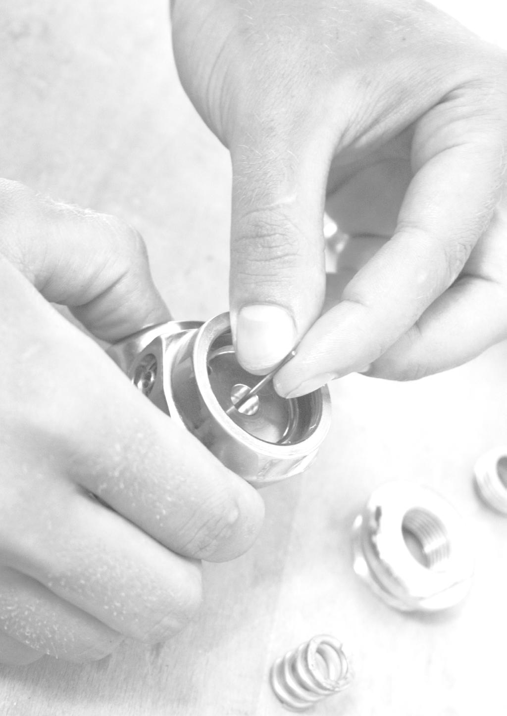
7 Functioning & Care During transport after a dive, the cylinder can end up buried under wet gear bags and wetsuits. The water dripping in the valve will stay there if not evacuated. When filling, this water will get into the cylinder. After several fills rather a lot of water can accumulate. Thanks to the construction of the cylinder valve (a small tube), this water cannot enter the regulator during a dive, but it will still cause problems. The water will speed up corrosion of the inside of the cylinder and it can cause first stage freezing when diving in cold water. The subject of regulator freezing will be covered in more detail in the next chapter. Another aspect of the care of the cylinder is to remove the neoprene cover from time to time to clean under it. The risk of corrosion at the outside of the cylinder is biggest at locations where the water cannot run off easily, creating a moist environment for longer periods of time. Some divers even recommend not using rubber covers on cylinders, but this increases the risk of damage to the foot of the cylinder. You could see this recommendation as solving one problem by causing a new one. Cylinder Valves Most cylinder valves are simple open and close valves. By adding or removing an insert, they can be used with either a DIN or international (yoke) regulator (number 4). The pressure in the cylinder is blocked with the valve (the soft part) which is closing against the seat (the sharp part number 1). The valve is part of the lower spindle (number 2), which is turned in and out with the help of a sort of screwdriver, called the upper spindle (number 3), which is connected to the knob. If a closed valve with no regulator attached gets under water, the entire area marked in blue will fill with water. A burst of air will only clear part of the water, because a big part is located behind the air flow. This will leave a residue of salt, dirt and minerals in the valve, which will interfere with smooth operation. Residue is specifically a problem when a twin valve is used, with only one first stage attached. If using a twin valve, you have to attach two first stages to prevent damage to the valve, or at least the unused valve has to be sealed with a waterproof plug. The water in the valve does not only pose a problem with the residue that is left in the valve. The water could also be forced into the cylinder during filling. As mentioned, water in the cylinder can cause corrosion and can cause first stage freezing in cold water, due to moist air. Liquid water cannot enter the first stage, thanks to the short section of pipe (number 5) under the valve. There are still many divers who do not open their valve completely. Once it used to be common to open the cylinder completely and then closing again half a Page 6

. This is required in some countries. Especially in those where the use of aluminium cylinders is common.")
8 Diving Equipment turn. This habit comes from the times where the mechanism of the valve was not split in an upper spindle and a lower spindle. Those valves could get blocked with decreasing cylinder pressure when opened completely. To prevent this, the habit of closing half a turn was taught. It is extremely rare to find the old types of valves in diving. There is no need at all for this procedure with modern valves. Just open valves completely. Some cylinder valves are equipped with a burst disc (number 1). This is required in some countries. Especially in those where the use of aluminium cylinders is common. The burst disc has no function for diving. It is a safety feature to protect fire-fighters when a storage area with diving cylinders catches fire. Aluminium gets weak before the O-ring between the cylinder and the valve would melt. This creates a risk of explosive release of pressure. With a steel cylinder, the O-ring would melt long before the steel gets weak. The burst disc is a small cupper plate that is rated to break (burst) when the pressure exceeds the rated pressure of the cylinder by about 15 per cent. This causes a hole through which the air stored in the cylinder can escape. The burst disc is kept in place by a plug. To simplify the above drawing, the hole is located at the end of the plug, but in reality, the holes are located on the side. Releasing the air through more than one hole at once prevents the cylinder from rolling. Burst disks are required in some countries, but for safe storage of aluminium cylinders, they are also recommended in other countries. In recreational diving a cylinder valve with a reserve (J-valve) is not common anymore. Some fire brigades and police divers still use them for zero visibility diving. The idea is that a spring loaded metal pin is pushed in an air passage. As long as the cylinder pressure is higher than the force of the spring, the air passes unrestricted. At lower cylinder pressures the pin enters the air passage, which reduces the diameter of the air passage. The smaller passage then increases breathing resistance. A diver who notices the increased breathing resistance is warned that the pressure in the cylinder is low and should end the dive. To use the remaining air without the increased breathing resistance, the diver can pull a rod down, which will pull the pin in the open position and keep it there. Some divers will not notice the increased resistance; some will forget to put the lever in the upward position before going diving and some reserves malfunction because of a worn spring or stay blocked in the open position. All this makes a reserve not a very reliable mechanism. When filling a cylinder with a reserve valve, the reserve lever must be in the down (open) position. The filling speed of a compressor is too high to pass through an opening which is restricted by the pin. As a consequence the valve is soon filled at 200 bar, although hardly any air got into the cylinder. The compressor will switch off automatically at the final pressure and the staff of the filling station will assume that the filling is done, but the cylinder will still be empty. The reserve will also restrict the air flow though the cylinder valve. This reduces the performance of the regulator. Page 7
9 Functioning & Care Regulators The choice of regulator is decisive for the comfort and safety of a diver. There are different designs for regulators, each having their own features, advantages and inconveniences. An uninformed choice will not only affect your comfort while diving, but can also become a safety risk. Regulators must be suitable for the local diving circumstances and the depth of a dive. This chapter starts with the functioning of the four different types of first stages. From these explanations it will become clear what the consequences of the choice for a specific design are. Three different types of second stages follow next. For second stages (in contrast with first stages) it is not possible to give clear criteria for the choice of a specific model. Based on the explanations, it will become clear which features are important in different diving conditions. The chapter is completed with an explanation on regulator freezing. After a general introduction it will become clear what the criteria are for the selection of a regulator for cold water diving. Page 8


10 Diving Equipment First Stages In order to explain the functioning of first stages, there are some basic concepts which need to be understood. For this purpose we consider forces as axial forces and radial forces. Axial refers to a force in the axis of movement and radial refers to a force which does not work in the direction of movement. A force with an angle between the two is split into an axial and a radial component. What you see in the drawing represents a sink with water. The sink is sealed with a plug. On the left, the plug is completely under water. The plug on the right is a plastic pipe of equal diameter for the entire length. On the left the weight of the water is working in the axis of movement, because there is a surface on top of the plug on which the weight of water can work. On the right the force is radial. The weight of the water is the same as on the left, but there is no surface provided on which the weight of the water can influence the movement of the plastic pipe. The plastic pipe is surrounded with water. Each force finds an opposite force which is equal. Movement will neither be assisted, nor restricted. On the left there will be a difference in the force required to remove the plug, proportional to the height of the water column in the sink. The same holds true for a high pressure chamber filled with air. The air surrounding the metal bar does not find a surface where it can assist or restrict the movement of this bar. There is no axial surface within the chamber. No matter how high the pressure in the chamber is getting, the bar is not going to move to the right or the left. The pressure in the chamber does neither assist nor restrict the movement of the metal bar. This would be different if the diameter of the metal bar would not be equal for the entire length. In that case the bar would move in the direction where the diameter is bigger. Another basic concept is that equal opposite forces annul each other. This concept is used in membrane first stages, which are in their functioning completely different from piston first stages. Two equal opposite forces, working on a surface with equal diameter annul each other. No movement will result and the resulting force is zero. If the force coming from the left is bigger than the force from the right and both are pushing on a surface of equal diameter, a movement (or force) to the right will result. The resulting force is equal to the force from the left, minus the force from the right. If the force coming from the right is bigger and the surface on Page 9
, but the surfaces on which the forces are pushing (expressed in mm 2 ) are not, movement or a force will result.")
.")

11 Functioning & Care both sides is still the same, the resulting force will lead to the left. If the pressures on both sides are equal (expressed in bar), but the surfaces on which the forces are pushing (expressed in mm 2 ) are not, movement or a force will result. The force is the result of: pressure from the left multiplied by the surface at the left minus force from the right multiplied by the surface at the right. For example: 200 bar x 20mm bar x 10mm 2 = 4,000 bar.mm 2 2,000 bar.mm 2 = 2,000 bar.mm 2 as a resulting force. (Correctly expressed in Newton 1 bar.mm 2 = 0.1 Newton). Theoretically it would be possible to annul the force of different pressures by adapting the surface on which the pressures are working. For example 100 bar x 20mm bar x 10mm 2 = 2,000 bar.mm 2 2,000 bar.mm 2 = 0 bar.mm 2. In diving, this is not used on many occasions, due to the variations in cylinder pressure which need to be taken into account. The understanding of these two basic concepts is essential to grasp the concept of the functioning of regulator first stages and many other equipment items. There are only 4 basic types of first stages. For each of them, multiple variations (gadgets) exist. The four basic types of first stages are: balanced piston first stage, non-balanced (traditional) piston first stage, balanced membrane first stage and nonbalanced membrane first stage. Although membrane first stages exist much longer, we will explore piston first stages first. Piston first stages were introduced in 1963 (non-balanced piston first stages) and 1965 (balanced piston first stages). In those days they represented a cheaper and more effective way to manufacture first stages for diving. You can recognize piston first stages by the holes allowing water to enter the ambient pressure chamber (as long as the holes are not under a plastic, neoprene or silicone cover). To explore the functioning of a balanced piston first stage, we return to the drawing we have seen in the introduction on first stages. This first stage is connected to a cylinder with a DIN valve. The moment the cylinder is opened, the chamber pressure of the first stage will become equal to the cylinder pressure, hence the name high pressure chamber. In the high pressure chamber, there is no surface allowing the pressure to exert a force in the axis of movement. There are only radial surfaces. The cylinder pressure has no influence on the movement of the metal bar which is called the piston. Page 10

12 Diving Equipment In figure 1, we add a second chamber to the first stage and give the metal bar the shape of a real first stage piston. In this new chamber, the piston is sealed with an O-ring, dividing the chamber in two parts. Both sides of the piston in the new chamber have a surface where pressure can influence the axial movement of the piston. This will not be high pressure (cylinder pressure) because an O-ring is sealing the passage from the high pressure chamber to the new chamber. In figure 1 the pressure in the new chamber cannot be defined, but it is certain that the pressure on both sides of the piston is almost the same. Both sides of the piston have an axial surface of almost the same size on which the pressure can work. The piston will move until it finds the position, in which the pressures on both sides find their equilibrium. In figure 2 we have drilled three holes in the new chamber. We connect a second stage to the hole at the left. The other two holes provide a connection with the ambient pressure. The pressure within the two parts of the new chamber can now be defined. The pressure in the chamber with the green arrows is equal to the pressure around the regulator. At the surface this is 1 bar. As a consequence, the pressure in the left part of the chamber is also 1 bar. If this would not be the case, the piston would move until both pressures are equal. If you would inhale from the second stage, you would pull the piston to the left. We can now name the two parts of the new chamber. The part with the holes allows ambient pressure to enter the first stage and is called ambient pressure chamber (or wet chamber). The part at the left has the same pressure as the hose leading to the second stage the pressure between the first and second stage and is called the intermediate pressure chamber. In figure 3, the piston is changed. Rather than being a metal bar, sticking out of the high pressure chamber at both sides, it now becomes a section of pipe. The bore trough the piston allows breathing gas to flow from the high pressure chamber to the intermediate pressure chamber. The far right end of the piston is now a seat a sharp edge which closes on a valve (made out of a softer material such as Teflon). As the sharp edge is cut on the inside, the external diameter at the side of the seat is equal to the external diameter at the other side of the high pressure chamber. The cylinder pressure does still not have any influence on the movement of the piston. If the diver takes a breath, the piston is pulled to the left. This action pulls the seat from the valve, allowing air from the high pressure chamber to flow to the intermediate pressure chamber and thus the intermediate pressure hose and the second stage. When the diver stops breathing, the piston will return to the closed position as soon as the pressure in the intermediate chamber is slightly higher than the pressure in the ambient pressure chamber. The first stage functions, but the intermediate pressure is only 1 bar (at the surface). As taught in beginner courses, the intermediate pressure is higher than that. We must add something to the first stage to create a higher intermediate pressure. What is added is a spring in the ambient pressure chamber (figure 4). This spring helps the ambient pressure in the attempt to open the piston. This means that the pressure that is needed in the intermediate pressure chamber to close the piston is higher. The pressure in the intermediate pressure chamber must be high enough to overcome the ambient pressure and the force that the spring is exerting on the piston. Page 11
 is added to the formula (such as cylinder pressure) the first stage is non-balanced.")
. That is the case for all regulators produced for diving today.")
13 Functioning & Care MP (Intermediate Pressure) = P Spring + P Ambient If this formula holds true, the first stage is called a balanced first stage. If a variable (positive or negative) is added to the formula (such as cylinder pressure) the first stage is non-balanced. The result is a regulator that offers equal breathing comfort, regardless of cylinder pressure. The term compensated refers to something else. This only means that the ambient pressure plays a role in the intermediate pressure (the green position in the formula). That is the case for all regulators produced for diving today. MP (Intermediate Pressure) = P Spring + P Ambient Compensated MP (Intermediate Pressure) = P Spring Non-compensated For a proper functioning of the second stage, the intermediate pressure must increase 1 bar for every 10 meters of depth, because the pressure in the second stage will also increase at that rate. When the intermediate pressure would stay the same, regardless of ambient pressure, at a certain depth the ambient pressure would exceed the intermediate pressure. Water would then enter, rather than breathing gas coming out of the regulator. The breathing comfort would reduce with increasing depth. Page 12


14 Diving Equipment A non-balanced piston first stage is constructed differently, but we will find many parts that are similar to those in the balanced piston first stage. A difference is the absence of a big high pressure chamber. The seat is now located in the body of the first stage, blocking the passage of high pressure air at the entrance. We now have two intermediate pressure chambers. One to the right, with the second stage attached, and another to the left, located behind the piston. The pressure in both intermediate pressure chambers is equal, because they are connected via the piston. The cylinder pressure is now arriving in the axis of movement. This means that the cylinder pressure does have an influence on the movement of the piston. The formula for a balanced regulator is not true anymore: MP (Intermediate Pressure) P Spring + P Ambient In some sort of way, the cylinder pressure has to find its way into the formula. Looking at the entrance for air, the diameter of the bore trough the high pressure seat is very small compared to the other side of the piston. Applying what we learned in the introduction on first stages, the calculation could be as follows 10 bar x 500mm bar x 3mm 2 = 5,000 bar.mm bar.mm 2 = 4,400 bar.mm 2 Or: intermediate pressure in the left chamber, multiplied by the diameter of the left side of the piston, minus cylinder pressure multiplied by the diameter at the high pressure seat. The result is the force missing to create the desired intermediate pressure (in this example 10 bar). That would be the force that the spring and ambient pressure need to exert. This means that the cylinder pressure is helping the spring to open the piston. The force of the spring would be less than the spring in a balanced regulator with the same intermediate pressure. The problem is that the cylinder pressure varies. If we look at the same equation at the end of the dive (when a diver would have only 10 bar pressure left in the cylinder), the result could be as follows - 10 bar x 500mm 2 10 bar x 3mm 2 = 5,000 bar.mm 2 30 bar.mm 2 = 4,970 bar.mm 2 This means that we would now need a spring with a different force (570 bar.mm 2 or 57 Newton more) in order to keep the intermediate pressure at 10 bar. The need for a varying spring force is ignored in the construction of virtually all non-balanced piston first stages. This leads to variations in intermediate pressure throughout the dive. Therefore the formula for a non-balanced piston first stage would be: MP (Intermediate Pressure) = P Spring + P Ambient + (x.p Cylinder ) The bigger x in the formula is, the bigger the variations in intermediate pressure between the beginning and the end of the dive. To keep x small, the diameter of the seat (3mm 2 in the given example) should be as small as possible. This forces the engineer to a compromise. He can opt for limited variations in the intermediate pressure, but that will come with limited flow (a small opening for the breathing gas). He can also opt for a bigger flow (a big opening for the breathing gas), but then has to accept big variations in the intermediate pressure and thus the change in breathing comfort when the cylinder pressure is decreasing. To keep the breathing comfort in an acceptable range, Page 13

15 Functioning & Care manufacturers produce non-balanced piston first stages with a small high pressure passage. The available passage allows enough air to pass for recreational dives at limited depth. When these regulators are used at greater depth and when a single first stage has to feed the main regulator, the octopus and an inflator, then it is doubtful whether the first stage can supply the amount of breathing gas the diver or divers are asking from the regulator. This is the reason why non-balanced piston first stages are not recommended as a personal regulator and why they are normally only used for training purposes in swimming pools and at limited depth. Non-balanced piston first stages cost less than other first stages and are easy to maintain. There is still a demand for them, but one should take care they are only used for the type of diving they were designed for. With balanced piston first stages we have no need to accept a compromise. No matter how large a diameter we provide for the high pressure air entrance and how big we make the bore through the piston, the formula to calculate the intermediate pressure will stay the same. MP (Intermediate Pressure) = P Spring + P Ambient Membrane first stages have the advantage that there is no contact between the moving (dynamic) part of the regulator and the water. The water only enters up to the flexible membrane (orange) and in this nonbalanced membrane first stage; there are no dynamic O-rings. When the diver is inhaling from the second stage, the membrane flexes inward, pushing the needle which will open the valve. The breathing gas can now flow from the high pressure chamber (with the orange arrow) to the intermediate pressure chamber (with the blue arrow) and to the second stage. When the diver stops inhaling, pressure will build up in the intermediate pressure chamber and the membrane will flex back against the force of the ambient pressure and the spring. The regulator will close. A difference with a piston first stage is that the high pressure does not work in the same direction as the spring it works in the opposite direction. This would result in the following formula: MP (Intermediate Pressure) = P Spring + P Ambient (x.p Cylinder ) Page 14

: MP.500mm 2 = P Spring.500mm 2 + P Ambient.500mm 2 + P Intermediate.4mm 2 + P Cylinder.16mm 2 P Cylinder.")
16 Diving Equipment The consequence is that the intermediate pressure will be higher with a low cylinder pressure and lower with a high cylinder pressure. This is the opposite of the non-balanced piston first stage. If the diameter of the conical valve would be 20mm 2 and the opening from the high pressure chamber to the intermediate pressure chamber would have a diameter of 4mm 2, then the complete formula would be as follows (equilibrium of forces): MP.500mm 2 = P Spring.500mm 2 + P Ambient.500mm 2 + P Intermediate.4mm 2 + P Cylinder.16mm 2 P Cylinder.20mm 2 The influence of the intermediate pressure on the diameter of the opening between the intermediate pressure chamber and the high pressure chamber (in this example 4mm 2 ) is very limited, for simplification we can ignore it. For the cylinder pressure we are only interested in the difference between the positive and the negative force (in this example 16mm 2 minus 20mm 2 = 4mm 2 ). This gives us the simplified formula: Or, in this example: MP.500mm 2 = P Spring.500mm 2 + P Ambient.500mm 2 P Cylinder.(Diameter MP-HP Passage) MP.500mm 2 = P Spring 500mm 2 + P Ambient.500mm 2 P Cylinder.4mm 2 Consequences for Adjustment For a technician who is adjusting the regulator, the type of regulator matters. A second stage needs to be able to close against the highest intermediate pressure a first stage will produce. This means that the adjustment of a non-balanced membrane first stage has to be done with a low cylinder pressure (just slightly higher than the desired intermediate pressure). If this type of regulator is adjusted using a full cylinder, it would start free-flowing toward the end of the dive. The opposite holds true for non-balanced piston first stages. These have to be adjusted with a full cylinder. If the technician is adjusting this type of regulator with an almost empty cylinder, it would freeflow when connected to a full cylinder. With balanced first stages the cylinder pressure during the adjustment has no importance. The cylinder pressure has no influence on the functioning of the regulator (as long as the cylinder pressure is higher than the desired intermediate pressure). Non-balanced membrane first stages are rare. There are a few older models which are still used by divers and there are still one or two manufacturers producing this type of regulator, but virtually all membrane first stages you find in a dive shop today will be balanced membrane first stages. There are two reasons for that. First of all the precision drills available today make the production of balanced membrane first stages a lot easier than it used to be. A second reason is that non-balanced first stages are not as durable as the balanced version. Page 15

17 Functioning & Care In the nineties, the balanced membrane first stage has become the most popular type of regulator for recreational diving. Even some manufacturers with a long tradition in piston first stages now have membrane first stages available. The big advantage is the lack of water contact with the moving parts in the regulator. This prevents salt, minerals, sand and dirt from entering the first stage, which substantially reduces wear. Balanced membrane first stages respect the formula for balanced first stages, but in a different manner than the balanced piston first stages. MP (Intermediate Pressure) = P Spring + P Ambient On first sight the functioning of a balanced membrane first stage is more complicated, but when we keep the information from the introduction to first stages in mind, the concept is easy to understand. The balanced membrane first stage is almost the same as the non-balanced membrane first stage. The addition is a balancing chamber that brings all forces in equilibrium. The entrance of high pressure, the connection for the second stage, and other intermediate pressure hoses are found at the same location as in the non-balanced membrane first stage. The functioning of a first stage of this type is based on the fact that equal opposite forces annul each other. The small piston has a passage to an intermediate pressure chamber (or balancing chamber). The first part of the bore is big enough for the needle to enter. The second part has a smaller diameter to prevent the needle from being pushed through the piston. The diameter of the intermediate pressure chamber is the same as the diameter of the passage between the high pressure chamber and the intermediate pressure chamber. This means that also the part of the small piston sticking out around the seat has the same surface above and under. This brings us the following complete formula for a balanced membrane first stage (assuming that the diameter of the passage between the high pressure chamber and the intermediate Page 16

18 Diving Equipment pressure chamber is 8mm 2 and that the part of the small piston sticking out around the seat has a surface of 10mm 2 ): MP.500mm 2 = PSpring.500mm 2 +PAmbient.500mm 2 +PIntermediate.8mm 2 PIntermediate.8mm 2 +PCylinder.10mm 2 PCylinder.10mm 2 As an identical + and annul each other and after deleting identical surface areas, the formula ends up the same as for the balanced piston first stage. MP.500mm 2 = PSpring.500mm 2 +PAmbient.500mm 2 +PIntermediate.8mm 2 PIntermediate.8mm 2 +PCylinder.10mm 2 PCylinder.10mm 2 MP (Intermediate Pressure) = P Spring + P Ambient To limit the need for precision in the construction of the small piston, some manufacturers bring the intermediate pressure to the balancing chamber is a different way. Rather than going through the small piston. A connection around the high pressure seat is created. The criteria for proper balancing stay the same. The diameter of the passage from the high pressure chamber to the intermediate pressure chamber needs to have the same diameter as the part of the piston sticking into the balancing chamber. The part of the small piston sticking out around the seat must have the same diameter on both sides. The only thing that changes is the way in which the intermediate pressure is brought to the balancing chamber. It is still a balanced first stage. The quality of a first stage is rather easy to define and can mostly be measured on a test bench. High flow, good stability of intermediate pressure at any flow and durability are the aspects to be taken into consideration. High flow is needed to give the second stage and accessories (and thus the diver) enough breathing gas at any depth for any demand. Stability of intermediate pressure at any depth and for any flow is needed to maintain a constant breathing comfort for the diver. Durability is needed to prevent the first stage from malfunctioning in any conditions and to assure a long life of the regulator. A first stage falling short of any of the above criteria cannot be considered a high quality first stage. This excludes non-balanced first stages from the label high quality, because of their variations in intermediate pressure and restrictions in the flow. Due to their construction they simply cannot match the performance of balanced first stages, so they do not belong in the same quality range. Considering durability, there are no doubts that membrane balanced first stages are your best choice. The membrane isolates the functioning parts in the regulator from the water, which assures that the regulator is protected from wear (under the conditions of pure air and correct rinsing procedures). It has happened that divers present their balanced membrane first stage after three or four years of daily diving without rinsing the regulator. They were still in good shape. This is unlikely with a piston regulator, due to water and galvanic action between a steel piston and the brass housing. The flow of a first stage must be high enough to accommodate the demand of a diver. With a consumption of 15 litres per minute at the surface, you could assume a diver to inhale this breathing gas in no Page 17

19 Functioning & Care more than 12 seconds (12 breaths in a minute, each lasting 1 second). That brings the breathing speed at the surface to 75 litres per minute for a diver who is relaxed and did not overexert himself. At a depth of 40 meters, this would be 5 times 75 litres/minute = 375 litres/minute for a second stage used by a relaxed diver. If we now add aspects such as an overexerted diver, the use of an inflator or another diver sharing air from an octopus connected to the same first stage, we could easily come to a needed flow well beyond 1,000 litres/minute for recreational diving and well beyond 2,000 litres/minute breathing speed for moderate technical diving. If the breathing rate is approaching the maximum flow of the first stage, the intermediate pressure will start to drop. This will increase breathing resistance and thus affect comfort. This is undesired in an overexertion situation, where an increased breathing resistance could cause a feeling of not being able to breathe. This in turn could cause panic and perhaps a diving accident. To achieve a stable intermediate pressure, the maximum flow of a regulator needs to be well beyond the breathing speed that can be expected from the diver (in worst case). Only first stages with a flow higher than 2,000 litres per minute can be considered to be high quality regulators for recreational diving (higher for technical diving). A non-balanced first stage mostly offers a flow below 1,500 litres per minute and reduces flow with decreasing intermediate pressure. Second Stages Distinguishing between a good second stage and a bad one is not as easy as with first stages. The first stage always has the same criteria durability, flow and stability of intermediate pressure. For a second stage there are more factors involved, including personal preference and the needs of the individual diver. This is a very diverse criterion. Second stages are either specially designed for specific diving conditions, or they are allrounder. The main problem with a second stage is that you cannot gain performance and benefit in all fields simultaneously. A second stage is always a compromise. For example: a longer lever can reduce the breathing resistance and thus improve the breathing comfort. When adding a longer lever, the internal volume of the second stage needs to be bigger. This will increase the dead air space and the diver will proportionally inhale more exhaled breathing gas with CO 2. This will cause more frequent breathing impulses and thus a faster consumption of the available breathing gas. In this case improving the breathing resistance comes with the compromise of a faster consumption of breathing gas. Some aspects to take into consideration for a second stage are: Durability Cracking pressure Inhalation resistance Exhalation resistance Changes in performance at different angles Page 18


20 Diving Equipment Dead air space Weight Flexibility on the hose connection and the flexibility of the hose itself Sensitivity to dirt, sand and salt or mineral residue Freezing It should be clear that we cannot reach the optimum for each individual consideration, without accepting a compromise in another. It would be possible to build a first stage and claim it to be the best in the world by proving that it has better flow, better stability of intermediate pressure and better durability than all others on the market. With a second stage you could never make such a claim, because you could never exceed the performance of all other available models in all fields. The only thing you can do is create a second stage that performs well on the aspects that you consider important and hope that they are what divers are looking for. A second stage that performs well in the tropics might be your worst choice in a cold climate. A regulator that offers fantastic performance during boat dives might free-flow constantly when entering the water through surf. When inhaling from a second stage, we distinguish between two moments. The force needed to activate the second stage, called cracking pressure, and the force needed to continue the inhalation, called breathing resistance. Regulator 1 has a high cracking pressure, but a relatively low breathing resistance. Regulator 2 is better on both aspects. Regulator 3 has a relatively low cracking pressure, but a high breathing resistance. The closer the resistance is to natural breathing, the better it is, but complete zero resistance like in breathing on land will not be possible. This would make the regulator too sensitive. Simply moving your head would already cause a free-flow. Many regulators are adjusted to a value of between 3 and 5 centimetres water pressure. Some regulators have features to adjust the breathing comfort while under water. Some of these features work on the cracking pressure and others on the breathing resistance. Those that alter the cracking pressure also have some influence on the breathing resistance. Before discussing the details of second stages, we will first look at some of the basics. The mechanism that activates during inhalation is also called the intermediate pressure seat. There are three basic types of second stages, which come in many variations: the traditional second stage, the downstream override and the pilot second stage. Next to allowing a diver to breathe, a second stage performs the function of overpressure relief valve, which should keep the system safe by free-flowing in case of a defect in either the first or the second stage. The key component of the traditional second stage is a spring loaded valve such as we find on a BCD as overpressure relief valve. The function of such a valve on a BCD is to prevent rupture of the bladder in case an inflator is stuck or a diver overinflates the BCD. You could say that the construction of the valve is done in such a way that if other technical elements or the user fails, the BCD is still safe. Or fail-safe. In a second stage, the valve serves the Page 19

 would not open the valve enough to allow for the flow that is needed for an")
.")
 must be strong enough to withstand the intermediate pressure.")
21 Functioning & Care same purpose. If there is a technical problem in the first stage, the construction of the second stage will keep the regulator safe. Also here this is called fail-safe. An overpressure relief valve of a BCD is often equipped with a cord that allows the diver to use the valve to dump air manually. The lever in a second stage is essentially the same. It is not a cord, but also a mechanism that is manipulated by the diver in order to open the valve. Only tilting the valve (as it would when a lever would be connected to the middle of the seat and moved to the side) would not open the valve enough to allow for the flow that is needed for an inhalation. This is why we find a mechanism that is lifting the entire valve from the seat. To do this, most valves are inserted in a small piston. Movement is created by the lever pulling at this small piston. The intermediate pressure from the first stage arrives at the seat (the blue arrow). The valve mounted in the small piston is pushed by the spring to keep the second stage closed. This means that the force of the spring (combined with the ambient pressure in the second stage) must be strong enough to withstand the intermediate pressure. Assuming an intermediate pressure of 10 bars, the spring is rather strong. The idea is that the spring is a little bit stronger than needed to close the intermediate pressure valve. All extra force will make itself noticeable in additional breathing resistance, because more force is needed to pull the valve free from the seat. This explains the changes in breathing resistance when using a non-balanced first stage. The spring in the second stage is adapted to the highest pressure that is to be expected from the first stage. The intermediate pressure will change with variation in cylinder pressure, but the spring in the second stage will keep the same force. The difference is noticed in the force that is needed to pull the valve from the seat (against the force of the spring). The breathing resistance (or at least the cracking pressure) will increase. When you inhale, the membrane is pulled inward and the lever is pushed down. Because of its shape, the lever pulls the small piston away from the seat. The lever can move all the way down in the second stage, resulting in a maximum opening between the seat and the valve. A diver manipulating the purge button cannot push the lever completely down. The construction of modern purge buttons only allows us to press the purge button down for a few millimetres. This is just enough to create the mild flow that is needed to purge the regulator or to clear it of water. Old second stages did not have a restriction on the purge button. The farther the lever is pushed down, the higher the flow from the second stage will be. To assure that a second stage can supply all the air a diver is asking in any situation and at any depth, it is necessary that Page 20


22 Diving Equipment the lever has the complete range of movement available. This is why the lever of a second stage needs to have contact with the membrane when under pressure. Only then the full range of movement is available and only this way the second stage can achieve its maximum flow when needed. You can check this by slowly moving a second stage under pressure and listening for lever movement. If you can hear the lever move freely, the second stage should not be used. The adjustment of a second stage mainly involves the positioning of the lever. If the lever is too high, the membrane will exert force on the lever and the second stage will free-flow. If the lever is too low, the range of lever movement available is too restricted to give maximum flow when needed. A second stage is not adjusted to the intermediate pressure of the first stage. The intermediate pressure for which the second stage is designed is defined by the spring in the second stage. The first stage is adjusted to the intermediate pressure the second stage requires. Not the second stage adjusted to the intermediate pressure the first stage gives. The traditional second stage is still the most common. You will find this mechanism for opening the second stage (the intermediate pressure valve) in the majority of second stages. The performance of this type of valve is good for almost all aspects, with one exception. The durability of this type of second stage is limited, especially if the regulator is not in use. It may sound strange, but these second stages do not last long when not in use. They last a lot longer when diving every day. The reason for that is the construction of the small piston with the valve, which is pushed by a spring that is strong enough to withstand intermediate pressure. When the regulator is in use, the force of the spring finds an opposite force in the intermediate pressure. The force with which the valve is pushed on the seat is almost zero. This would cause only very limited wear of the valve. This is different when the regulator is not in use. There is no intermediate pressure pushing the valve, but the spring is still strong enough to withstand a non-present force. The valve is pushed on the seat with a rather big force. This will carve the soft material of the valve (1). A consequence of a damaged valve (2) is that the small piston will have to travel further to close the entrance of breathing gas. This will bring the lever higher up than its adjustment when the seat was still in order. This causes a mildly free-flowing second stage which needs either to be readjusted, or the valve must be replaced. This problem typically occurs when the regulator has not been in use for a while. It could belong to a diver who stops diving over winter. It could also be a regulator in the back of the rental department, which is only used during peak demand. We are normally confronted with this problem at an unexpected moment, because we assumed that the regulator would still be in the same good shape as when we stored it. Downstream Override second stages are sometimes (mistakenly) called balanced second stages. They are not very different from the traditional second stage, but apply a balancing chamber (similar to the one in the balanced membrane first stage) to assist the spring in closing the valve against the seat. This allows for a weaker spring and reduces the problem of carving the valve when the regulator is not in use. It also Page 21


23 Functioning & Care allows for a lighter mechanism which could react faster than the traditional model. As everything in second stages, this comes at a price. The second stage is more sensitive to dirt, sand and salt or mineral residue. Compared to the piston in the traditional second stage, the downstream override version has a hole drilled through the piston, leading to the balancing chamber, which is sealed with an O-ring. The intermediate pressure pushes the small piston from both sides, so the only force missing is a force to close the valve when the diver stops inhaling. This is the role of the weak spring. If the system would work completely according to the above principle, we could actually name this second stage a balanced second stage. This is not the case. As mentioned before, the second stage fulfils two roles. It allows the diver to breath and it serves as a safety valve (overpressure relief valve) for a malfunctioning first stage. If the system would be completely balanced, the second stage would not work as a safety valve anymore. The pressure in the balancing chamber is identical to the pressure in the intermediate pressure hose. Even at a pressure of 200 bars, the valve would still not open. To solve this problem, pressure in the balancing chamber and the hose are identical, but not the surface on which this pressure is working. The diameter on which the intermediate pressure can work in the chamber is almost half of the surface at the side of the hose. This way the balancing chamber is assisting the spring, but not replacing it. The spring is still doing half of the work. We override the lack of safety valve (downstream) function by working with different diameters, rather than really balancing the second stage. This is why the problem of carving the valve (when the regulator is not in use) is reduced, but not solved completely. The pilot second stage is using an upstream valve. A pilot second stage is using a small stream of breathing gas to open the passage for a big stream of breathing gas. A tube is connected to the intermediate pressure hose. The breathing gas coming from the first stage can enter unrestricted. Within the main tube leading to the membrane and the mouthpiece, there is a second tube with a tiny entrance through which the intermediate pressure can enter. When you open the cylinder, the regulator will free-flow, but the free-flow will stop as soon as the inner tube is under pressure. The pressure will push the flexible material around the inner tube to seal against the outer tube. The hole through which the breathing gas enters the inner tube is very tiny. It will take almost a second until the initial free-flow will stop. When the diver inhales, the small upstream valve at the right is tilted and the pressure in the inner tube is released to the right. The hole created by opening the small upstream valve is larger than the tiny hole at the left. The tube releases breathing gas faster than it can be replenished. This will cause the flexible material to lose its seal with the outer tube. That action will open the big stream of breathing gas. You can imagine these regulators to have a very high cracking pressure, but an extremely low breathing resistance and an extremely high flow. Regulators like these are popular for diving in very cold water, but the big difference between the cracking pressure and the breathing resistance decrease the breathing comfort to an extent that it is not Page 22

.")

24 Diving Equipment a choice of divers who have the option of freely choosing their regulator. For cold water diving these second stages work very well, because the flexible material would even close against ice. A problem with pilot second stages is that they are not fail safe. They do not function as a safety valve. The higher the intermediate pressure, the better the flexible membrane will seal against the outer tube. This is why a regulator with a pilot second stage has an extra over pressure relief valve (safety valve to make the system fail safe). Such a safety valve can be added to one of the intermediate pressure ports on the first stage, or it can be part of the intermediate pressure hose connection to the second stage. This is a spring loaded connection which will create an opening between the second stage and the hose to release excess breathing gas at too high pressure. Regulator Freezing When diving in cold water, a frozen regulator may cause a free-flow. For ice to develop, two factors are required: temperatures below zero and water. If one of the two is missing, a regulator will not freeze. It is very unlikely that a first stage will freeze. Cold temperatures are caused at the location where the pressure drops. In the first stage this is at the high pressure seat. No matter which type of regulator we take, membrane or piston, balanced or non-balanced, at the location where the temperature drops when the diver inhales, there is normally no water. If there is water at the location of the high pressure seat, this is coming from the cylinder. This is one of the reasons to prevent water from entering the cylinder, as is explained in the chapter on cylinders and valves. Moist air entering the first stage can cause water to accumulate around the high pressure seat. This water can freeze if the temperature drops below zero. The ice can prevent the valve from sealing against the seat. It is recommended to verify that the inside of the cylinder is dry, before the cold season starts. Some first stages are equipped with features to prevent icing. Most of these do not really work, because the added isolation is far away from the actual problem. The temperature drops below zero only at the high pressure seat. The first stage is made out of metal (a good heat conductor) and the regulator is immersed is water with a temperature above zero (we do not dive in ice). When you inhale, the tem- Page 23

25 Functioning & Care perature around the high pressure seat drops below zero (which is no problem as long as the air from the cylinder is dry). However, thanks to the above zero temperature of the surrounding water, the area will warm up again before you take the next breath. Isolation around the intermediate pressure spring can serve to keep minerals and salt out of the ambient pressure chamber, and help to prevent the regulator from freezing before and after the dive. It does not help underwater. Rather than adding this kind of feature, you should make sure that the cylinder is completely dry inside. At some point in time, divers made it a habit to fill the wet chamber of piston first stages with silicone grease. This created the opposite effect. Rather than keeping sand and dirt out of the first stage, the silicone trapped it inside the ambient pressure chamber. Every time the piston moves, silicone is pushed out via the holes in the first stage and water (with salt and dirt) is pulled in. The sand, dirt and salt stick to the silicone and create a mix of silicone and dirt which is not really good for the first stage. It was also rather annoying that small quantities of silicone came out of the holes when the first stage was put under pressure, causing a greasy, slippery first stage. The second stage is a different problem. There is moisture in the second stage, so temperatures below zero can cause regulator freezing. The moist air the diver is exhaling can bring enough water in the second stage to cause ice around the intermediate pressure seat. For the second stage, the only chance we have against freezing is therefore to keep the temperature around the seat above zero. Page 24

26 Diving Equipment The pressure drop of a single breath (intermediate pressure to ambient pressure) does normally not cool the second stage enough to freeze. To keep the temperature in the second stage above zero, we need to make use of the ambient temperature, which is always above zero. The second stage must be warmed up before you inhale again. This requires a good conductor and as little isolation as possible between the inside of the regulator and the ambient temperature. The best available conductors are metal and carbon. For that reason many who dive in cold water have metal or carbon second stages, both for the main second stage and for the octopus. Second stages with a complete metal or carbon casing are the best choice for diving in cold water. To solve the problem with plastic second stages, some manufacturers add metal parts. Although this cannot be the equivalent of a complete metal second stage, normally this works well. The quantity and the size of the metal parts must be sufficient. The regulator in the picture has another feature to prevent the second stage from freezing. The lever is placed on the opposite side of the casing, as far away from the intermediate pressure seat as possible. The mechanism is attached to a plastic (non-temperature conductive) rod. This way the moving parts of the regulator are far away from the location where the temperature drops. The risk of second stage freezing is further reduced. Metal or carbon second stages are not the only solution to prevent a regulator from freezing, but it is the simplest one. Page 25
27 Functioning & Care Other Equipment Items A book about diving equipment is not complete without information on other options for breathing underwater and on additional equipment with technical features. Masks, snorkels and fins or similar items are not part of equipment with technical features. These items are sufficiently covered in textbooks for beginning divers. This chapter starts with another option than diving regulators. For that purpose, the features and functioning of four different types of rebreathers are explained. The next part covers equipment items that are connected to the regulator, such as inflators, SPGs and pneumatic systems. This chapter also provides input on the use of diving equipment with Nitrox. The chapter is concluded with information on diving instruments. Page 26

28 Diving Equipment Rebreathers When diving with air, we inhale 21 per cent oxygen. When using open system scuba (a regulator), at the surface we exhale 17 per cent of the oxygen unused. The same would apply to Nitrox. When diving with Nitrox36, at the surface, we exhale 32 per cent of the oxygen unused. When depth increases, the percentage of oxygen used decreases (when the effort of the diver stays the same). A diver breathing air (21 per cent oxygen) at a depth of 30 meters (4 bars) will exhale 20 per cent of the oxygen unused. With the same effort, the diver will use the same quantity of oxygen molecules. At 30 meters depth the density of the gas in the lungs is four times higher, meaning that the same percentage (21 per cent) represents four times as many oxygen molecules. Increasing the number of oxygen molecules does not increase the amount of oxygen used in the metabolism. The quantity of unused oxygen increases with depth and with an increased percentage inhaled. Depth O 2 inhaled O 2 exhaled CO 2 exhaled O 2 inhaled O 2 exhaled CO 2 exhaled Surface 21% 17% 4% 36% 32% 4% 10 metres 21% 19% 2% 36% 34% 2% 30 metres 21% 20% 1% 36% 35% 1% This means that when diving with open system, we waste a lot of unused oxygen. Long before the development of open system scuba, military divers were already using rebreathers, which make use of the exhaled oxygen by recycling the exhaled breathing gas (removing the CO 2) and using it again to make more efficient use of the available oxygen. In the nineties, rebreathers have become an option for recreational divers. Before that they were exclusively used by the army. All rebreathers share some common features. All have a breathing circuit with valves, which direct the breathing gas to always pass through the circuit in the same direction. All have a mouthpiece that can be closed to prevent water from getting into the circuit when the mouthpiece is taken out of the mouth. All rebreathers have a flexible part in the circuit, called the counter lung, which increases in size when the diver exhales and decreases in size when the diver inhales. This means that the sum of the counter lung volume and the volume of the lungs of the diver is always the same. The buoyancy of the diver is not affected by breathing. Exhaling to descend does not work with a rebreather. Because there is a flexible part, the rebreather is affected by Boyle s law, increasing and decreasing the volume when changing depth. To prevent a rupture of the circuit while ascending, rebreathers are equipped with an overpressure relief valve. The spring in the valve defines the maximum pressure in the circuit. All rebreathers, regardless of type, model and make, release bubbles when ascending. Page 27

29 Functioning & Care The last common part for all rebreathers is a canister with soda-lime. Soda-lime is a chemical that binds with CO 2, thus removing it out of the exhaled breathing gas. Each pellet of soda-lime can bind with a certain number of CO 2 molecules. As we have read in the introduction and seen in the table on the previous page, the number of CO 2 molecules (not the percentage) stays the same regardless of depth (provided the level of activity of the diver stays the same). A given quantity of soda-lime which will be enough for three hours at the surface will also be enough for three hours at a depth of 30 meters. The main technical difference between the different types of rebreathers is the way in which fresh breathing gas is added to the system. The type of rebreather is defined by the type of gas which is added to the system and the way this is done. For simplification we distinguish between four types of rebreathers: Closed Circuit Oxygen Rebreather Semi-Closed Oxygen Rebreather Semi-Closed Nitrox Rebreather Closed Circuit Mixed Gas Rebreather The closed circuit oxygen rebreather is equipped with a small cylinder with pure oxygen. Within the counter lung, we find a lever, similar to the lever in the second stage of a regulator. The diver inhales the breathing gas out of the circuit and then exhales into it. The exhaled gas passes through the canister, where the CO 2 is reacting with the soda-lime. This will lead to a loss of volume (the CO 2 is missing). When the loss of volume is sufficient, the counter lung volume will decrease so much that the lever is activated and fresh oxygen is flowing into the counter lung. This means that new gas is only added to the system in case of a loss of volume. Although such a loss of volume can be caused by descending (Boyle) or a diver exhaling from the nose (allowing the gas to be lost to the environment), the normal reason for the loss of volume is the gas consumption by the diver. This means that the actual consumption of the diver is taken into account in the quantity of fresh gas that is added to the system. If the actual consumption is taken into account, we call the rebreather a Closed Circuit Rebreather or CCR. The word closed does not mean it is actually a closed system. The system cannot be closed due to the presence of flexible parts and the exposure to changing ambient pressures. From a safety point of view, the closed system oxygen rebreather is not a choice for every diver. The gas in the system is not the same as the gas in the cylinder. The diver does not breathe pure oxygen. There will be nitrogen in the system. Before the dive the rebreather and the lungs of the diver will be filled with air (almost 80 per cent nitrogen). When the diver takes the mouthpiece in the mouth and starts breathing from the rebreather (without taking any precautions) he can only reduce the volume by a maximum of 21 per cent. By then all the oxygen is used, but the nitrogen in the system would still be there (nitrogen is not absorbed by the soda lime and the body of the diver is already saturated with nitrogen and will not take any from the circuit. A maximum reduction of volume by 21 per cent could be too little to activate the lever in the counter lung. The diver would lose consciousness due to hypoxia (or even anoxia). To prevent this, the diver has to exhale and empty the counter lung before taking the mouthpiece in the mouth and then add oxygen Page 28
 when the diver has consumed oxygen from")
30 Diving Equipment from the cylinder to the system. This would bring a more favourable mix of nitrogen and oxygen, allowing a loss of volume which is enough to activate the lever (and thus the oxygen injection) when the diver has consumed oxygen from the system. The routine of emptying the lungs and counter lung before the dive is easily trained and learned. It is harder to get the diver to remember to repeat the procedure at the end of a short return to the surface to check a compass bearing or to discuss with the buddy. Even one breath of air with the mouthpiece out is enough to increase the nitrogen content in the system dramatically. This is one of the reasons why many prefer to dive with a semi-closed oxygen rebreather. Because the actual gas the diver is breathing is not oxygen, but Nitrox (due to the nitrogen that keeps circulating) the maximum depth for this type of rebreather is more than 6 metres (oxygen can become toxic at a partial pressure of 1.6 bars 6 metres would be the maximum depth with pure oxygen). Increasing the maximum depth beyond 6 metres is not without risk. A diver with a leaking mask would clear the mask of water a few times each minute. Every time the mask is cleared, breathing gas is lost from the circuit. The lost gas includes oxygen and nitrogen, but only pure oxygen is added. Step by step the percentage of oxygen increases and with that the partial pressure of the oxygen at the depth of the dive. If the diver is deeper than 6 metres, this could cause the partial pressure of the oxygen to become higher than 1.6 bars. This will bring the diver at direct risk of a fit due to the toxic properties of oxygen at elevated partial pressures. In that case it is possible the diver will drown. The semi-closed oxygen rebreather is a bit more predictable and has a lower risk of hypoxia (or anoxia). In this case the counter lung is not equipped with a lever, but an orifice which is set to inject a fixed quantity of oxygen into the system every minute. The amount of oxygen injected is fixed and thus needs to accommodate the demand of the diver in any thinkable situation. The diver could be taking macro pictures, which could decrease the oxygen consumption below 0.5 litres per minute, or the diver could be swimming against a strong current, which could increase the oxygen consumption to 2 litres per minute. Getting too much oxygen is not a problem (apart from a situation where this would cause the partial pressure of oxygen to be higher than 1.6 bars). Getting too little oxygen will cause hypoxia and thus unconsciousness. This is the reason why the orifice is set for the assumed worst case. In the above example the orifice would be set to inject 2 litres of oxygen each minute. If the diver does not use all the oxygen, the rest will bubble out of the overpressure relief valve. Because both nitrogen and oxygen are bubbling out of the system, but only oxygen is added (apart from the nitrogen de-saturating out of the body of the diver), the oxygen percentage will be higher than in a closed system oxygen rebreather. Hence it is more important for the diver to respect a reasonable maximum depth. A semi-closed Nitrox rebreather functions in exactly the same way. Closed Circuit Rebreather (CCR) Semi Closed Rebreather (SCR) = injection based on measured O2 consumption = injection based on assumed O2 consumption Page 29

31 Functioning & Care The construction of the semi-closed Nitrox rebreather is the same as the semi-closed oxygen rebreather, but the amount of breathing gas injected is higher. This cannot be calculated linearly. You cannot say that if the oxygen consumption of the diver would be 2 litres per minute, it would be enough to inject 4 litres of Nitrox50 each minute. This would be 2 litres of nitrogen and 2 litres of oxygen. You have to account for the oxygen that is lost via the overpressure relief valve. Semi-closed Nitrox rebreathers allow divers to make long dives, but fluctuations in the percentage of nitrogen and oxygen in the breathing circuit come with a few inconveniences. We calculate the flow based on the amount of oxygen that is needed to keep the gas in the circuit above hypoxic levels. This means that a diver who is actually using the assumed consumption of two litres of oxygen per minute will be breathing air. Without an integrated analyser you never know how much oxygen you are actually consuming. The only correct procedure would be to set the dive computer (for the nodecompression limit calculation) for air. In contrast, mask clearing or other actions (such as a bag purge, which is learned in a rebreather course) could fill the entire system with fresh breathing gas from the cylinders. This means that the maximum depth should always be based on the oxygen percentage in the cylinder. The need for worst case settings gives the diver rather a few disadvantages. With instruments measuring and calculating in real time, the disadvantages can be reduced. It will however still not be comparable to open system scuba, where it is always clear to the diver what he is actually breathing. A closed circuit mixed-gas rebreather is more complex than the other rebreathers. The reason for that is that we cannot measure the consumption of oxygen by measuring a loss of volume. The diver is using a mix of gases and the loss of volume does not give any information about which of the gases is missing. This is why closed system mixed-gas rebreathers measure the partial pressure of oxygen in the system electronically. In most systems, three sensors measure the oxygen and provide this data to the calculator. The diver can read the measured partial pressures on two displays. The calculator can now compare the measurements to the desired oxygen partial pressure that was set. It is the diver who sets the desired oxygen partial pressure. Mostly the diver decides between a low setting (for example 0.7 bar) and a high setting (for example 1.3 bars). If the calculator finds the measurements lower than the desired oxygen partial pressure, it will activate an electronic injector until the oxygen partial pressure in the system is at the desired value. The diver manually operates the addition of diluents. This can be air, pure nitrogen, helium, a helium/nitrogen mix or other. The diver uses the diluents to control buoyancy. The diluents are inert gases and stay in the system. The diver only has to inject additional gas in the case of loss of volume and thus loss of buoyancy. Units like these are not recommended for recreational diving. The maintenance needed is very time consuming and costly. The electronic circuit needs to be protected against water, which can for example Page 30
32 Diving Equipment be done by leading all electrical wires through intermediate pressure hoses. The sensors need to be replaced periodically and the electronic injector has to be verified for proper functioning on a regular basis. The time needed for all of this, as well as the investments it requires normally go beyond the limits for time and money a recreational diver is willing to invest. Next to the maintenance concerns, these units have a bad reputation. This is caused by a number of fatal accidents. Most of these accidents were caused by diver mistakes, but you must be aware that these units offer many opportunities for a diver to make such a mistake. An example is a diver who is diving on high setting (1.3 bars) at a depth of 10 metres. When the diver quickly descends to a depth of 30 meters, without adding diluents (the system does not do this automatically), then the oxygen partial pressure would increase instantly to 2.6 bars. This would cause oxygen toxicity and it is likely that the diver will drown, just because he forgot to add diluents to the system. Another example would be a diver returning at the surface after a dive and still having a setting of 1.3 bars. At the surface, the calculation unit will be given information that the oxygen partial pressure is too low (at the surface the total pressure is 1 bar, so the oxygen partial pressure cannot get higher than that). The diver hears the electronic injector injecting like mad. To save oxygen, the diver closes the valve of the oxygen cylinder. If the diver has to descend again for whatever reason, the system will be hypoxic within a few breaths and the diver will lose unconsciousness. Closed circuit mixed-gas rebreathers have one enormous advantage for commercial and military diving. They do not work with a constant oxygen percentage, but a constant oxygen partial pressure. This means that there is (theoretically) no maximum depth. The partial pressure of oxygen will never exceed 1.6 bar and the diluents can be chosen for the desired depth. Returning to a decompression-stop at 3 meters depth, the diver will (after a while) breathe mainly oxygen. Nitrox and Equipment A need for special attention for diving equipment that is used with Nitrox varies with the partial pressure of oxygen it gets in contact with. In the early days of Nitrox diving, we tended to overdo it a bit with the special attention. You could find cylinder valves that were cleaned with trichloroethylene, a substance which causes more risk to the person handling it than the risk the grease particles on the equipment could ever pose to the diver. As divers we see no problem in using a regulator dripping with grease on an air cylinder at 300 bars, but we get nervous with traces of grease on a regulator used for a Nitrox32 cylinder at 200 bars. In reality, the partial pressure of oxygen is almost the same in both cases. 200 bars x 0.32 = 64 bars and 300 bars x 0.21 = 63 bars. The above does not imply that we can ignore any grease on the equipment and that we can use whatever we want. It all depends on the partial pressure of oxygen, the energy (heat) in which it is handled and the self-igniting characteristics of the materials in contact with the oxygen. An accepted rule in the diving industry is that all gases up to an oxygen content of 40 per cent are handled as if they were air and that all gases with an oxygen-content above 40 per cent are handled as if they were pure oxygen. This is for example done when filling Nitrox cylinders. Gases mixed at ambient pressure can only be compressed in an oil lubricated compressor if the oxygen content is 40 per cent or lower (provided that the law in the country where the compressor is used allows this). For higher blends, the blender will make use of the partial pressure method. If the cylinder and valve get in contact with blends with an oxygen-content above 40 per cent, they need to be cleaned periodically. The norm for oxygen compatible air still allows a certain residue of hydrocarbons. When a cylinder is filled several times, these will accumulate in the cylinder and at some point they will reach a critical value. Again, it all depends on the energy and the self-igniting characteristics of Page 31


33 Functioning & Care the residue in the cylinder. It is impossible to give a precise procedure, so the only prudent thing is to do regular cleaning for oxygen compatibility. Those procedures are learned in blender courses. All other equipment items should be serviced and maintained according to manufacturer recommendations. This mostly involves that an oxygen compatible lubricant must be used and that in all high pressure areas O-rings are to be Viton (or similar). The manufacturer s maintenance manuals will give detailed information. For open circuit recreational diving we rarely use blends above Nitrox36. For these the concerns are limited, if not theoretical (for the diver and not the blender). In general it is not advised to use aluminium and titanium for Nitrox, but also here several factors must be taken into account. The bottom-line is, that we should take precautions for equipment being used with Nitrox, but that these are limited and that it is the manufacturer of the equipment who is responsible for appropriate recommendations. These recommendations are to be considered binding for the diver and the service technician. Inflators & BCD Valves is confronted with a lack of buoyancy at greater depth will want to be able to establish neutral buoyancy without too much delay. This is the main reason why it is not recommended to attach any signalling devices between the inflator hose and inflator. Some devices can reduce the performance of the inflator by more than 50 per cent. The aspect of flow is especially important when you dive with a combined inflator/regulator. In that case, a second stage is combined in the same housing with an inflator, allowing the diver to inflate and deflate the BCD and to breathe from the same mouthpiece. There are no parts which are not already introduced. The second stage has a normal membrane and lever and is equipped with a normal intermediate pressure valve and seat. The inflator has the same mechanisms as a normal inflator. The only added feature is that all these parts are combined in the same housing. The air supply for a second stage and an inflator cannot be adequately delivered via a normal inflator hose. This is why The inflator allows the diver to use air from the cylinder to inflate the buoyancy control device (BCD). The inflator hose is connected to the first stage at one of the free intermediate pressure ports. It has a quick connector at the other end to be connected to the BCD (and/or dry suit) inflator. The inflator is rather simple compared to a regulator. Just like with regulators, flow is an important factor for an inflator. A diver who Page 32

34 Diving Equipment you will find them to be equipped with an oversized quick connector. Inflator/regulators are popular in some areas. In an out of air situation, the diver will give the primary second stage to the diver who is out of air and will breathe himself from the inflator/regulator. However, they combine many parts in a single housing, which makes them sensitive and because of that less popular in areas where surf entries are made. For the inflator mechanism, there are 3 common types. All have a spring loaded button which opens a passage to allow the air from the intermediate pressure hose to flow into the BCD. The mechanism to the left has only one O- ring. The piston has a conical shape at one end, sealing the passage for breathing gas. When the button is pushed, the seal will break and air will flow into the BCD. The spring will force the piston back in sealing position when the diver stops pushing the button. In the second model, the seal will break when pushing the button, because the conical shape of the housing will not allow the lower O-ring to seal when the button is depressed. The third model uses the upstream valve we know from the pilot second stages. As a matter of fact, it can be the same valve as is found in the inflator hose (and in bicycle tires). Many BCDs are equipped with a quick release valve at the location where the corrugated hose is attached at the BCD. A cord attached to the inflator allows the diver to activate the quick release valve by pulling the inflator down. The quick release valve also functions as an overpressure relief valve. The overpressure relief valve is a spring-loaded downstream valve. The force of the spring specifies how much pressure is allowed in the container, which is protected against overpressure. The BCD is equipped with such a valve (in most cases more than one). Most overpressure relief valves have a cord attached to them to allow the diver to manipulate them manually in case they want to dump air from the BCD. The care and maintenance for these valves is simple and does not take much time. There are hardly any parts to be replaced, so cleaning and verifying for proper functioning and wear are the only things to be done. Some newer quick release valves are equipped with a pneumatic valve. When the diver pushes a button, intermediate pressure enters a flexible tube which pushes a small spring-loaded piston under the valve in the up position, opening the quick release valve (most of these systems open more than one valve at the time, allowing the air to escape through the one in the highest position). When the diver stops pushing the button, the pressure in the flexible tube returns to ambient pressure. The spring will now be strong enough to push the small piston back in the lower position and the quick release valve(s) will close. Some divers have a preference for these systems, as it is not anymore needed to lift the arm with the inflator hose to make the inflator the highest point. Others do not like the system at all. They see a safety concern in the fact that the pneumatic system needs pressure to function, which would make it impossible to use the system in an out-of-air situation. Others find it harder to fine-tune their buoyancy with these systems than with a traditional inflator system. Page 33

. The other side of the O- ring is at the same pressure as the pressure in the cylinder.")

35 Functioning & Care The traditional quick release valve (left) and the inflator unit (middle) on the jacket, which operates the pneumatic quick release valves (right). Instruments Submersible pressure gauges are connected to the high pressure chamber from the first stage via a high pressure hose. At the side of the SPG, they are equipped with a swivel that allows the diver to turn the SPG, to allow easy reading of the pressure in the cylinder by turning the SPG. The swivel is a sensitive part. The section between the O-rings is in contact with water (and salt and minerals). The other side of the O- ring is at the same pressure as the pressure in the cylinder. Every time the diver turns the SPG, the O-rings are moving. The O-rings are dynamic O-rings and they need appropriate care. A leaking O-ring at the swivel will make itself noticed by a stream of tiny bubbles coming out of the protection cover or console. After the swivel the air enters into a spiral tube. The tube will roll out with increasing pressure. This will move the needle on the SPG. A pressure gauge has an open bourdon tube. This means that the pressure (200 bars or more) enters the small tube inside the SPG. In the tube the pressure exerts its force on the entire inside wall. Thanks to the bent shape, the diameter of the outer wall is bigger than the diameter of the inner wall, which will cause a force attempting to straighten the tube. When the spiral rolls out, the needle is moved and you can read the pressure on the SPG. Normally there is no pressure inside the housing of the SPG, so it is not built to withstand pressure. If the tube is Page 34


36 Diving Equipment damaged and pressure is released into the housing, the housing cannot withstand that pressure and will break violently. To prevent this from happening, the SPG is equipped with an overpressure relief valve. This valve should allow the pressure to escape from the housing, before it reaches a value that would break the housing. In many cases it is a piece of plastic that pops out before the pressure is too high. A console or protection cover should have a hole which is located exactly in front of the plastic plug. A console without such a hole, or a hole on a wrong location could prevent the piece of plastic from popping out and could allow the pressure in the SPG housing to increase to a value which the housing cannot withstand. This problem could be caused by divers who insert non-original instruments in a console. Today most depth gauges are digital, working with a pressure sensor which changes the electronic resistance with pressure. The resistance is converted to a depth reading on the display of the instrument. Other than rinsing with fresh water, cleaning the console, keeping the instrument out of direct sun light and changing the batteries (and sometimes not even that) there is not a lot a diver can do with respect to maintenance and care. Most dive computers allow the user to enter specific data concerning the dive, such as the Nitrox blend, the altitude and an estimation of the diver s personal susceptibility to decompression sickness. They also gather data for logbook purposes and statistics. Traditional depth gauges often have a bourdon tube. It can be compared with the one we find in the SPG. In this case it is a closed bourdon tube. This means that the pressure does not enter the tube, but exerts its force on the outside of a closed tube. As a consequence the tube does not roll out, but it rolls inward to move the needle that indicates the depth. During production the tube is filled with gas (and thus at atmospheric pressure) and then sealed. The housing is filled with a liquid that transfers the pressure to the tube. Different gases or liquids have resulted in different names for these bourdon tube depth gauges. The principle is the same for all: helium depth gauges, oil filled depth gauges, etc. This is to indicate that the tube is filled with helium or that the tube is lying in an oil bath. Most of these differences were an attempt to solve the biggest problem of these gauges. That is the sensitivity to changes in temperature. Extreme temperature differences could affect to accuracy by several meters. Because of changes in altitude (and to a lesser extent changes in temperature and atmospheric pressure at sea level) it could happen that the needle of the depth gauge was not indicating zero metres at the surface. If the needle would read 2 meters below zero at the surface, it would read 18 meters at 20 meters depth and 28 meters at 30 meters depth. Membrane depth gauges have the same problem. This is why you will find most of these Page 35
.")
37 Functioning & Care types of depth gauges to be equipped with a small hand wheel that allows you to readjust the scale to zero before starting the dive. A diver who set the scale for zero before the dive will read the real depth during the dive (with a difference of about 3 per cent between fresh water and salt water). A membrane depth gauge is filled with a gas. With increasing pressure, the (metal) membrane flexes inward which pushes on a mechanism that transfers the loss of volume in the housing in needle movement to indicate the depth. In both of these types of depth gauges, the movement of the tube or membrane is more or less linear with increasing pressure. This means that the reading of the gauge is still more or less accurate at greater depth, but that it might be harder to maintain the depth of a safety or decompression stop. These types of depth gauges were popular in the times when diving was exclusively done with dive tables. Dive tables require the diver to calculate the entire dive as if it were made at the greatest depth. This is the reason for the second (red) needle. It is pushed by the main needle, but will not move back to zero with it. This keeps the needle at the greatest depth reached during the dive and thus the depth the diver needs to use for dive table calculations. If such a needle is blocked, the problem can be solved with a mix of warm water and vinegar. In most cases the blockage is due to salt crystals under the button. A capillary depth gauge was sometimes used to solve some issues with the bourdon and membrane depth gauges. These are the accuracy of the safety or decompression stop depth reading and reading the real (and not the theoretical) depth for dives at altitude. The capillary depth gauge is a tube with a very small diameter (hence the name capillary). The diameter of the tube is less than the surface tension of a drop of water, meaning that we cannot pour water in or out of the tube without using additional force (pressure). The tube mimics a container filled with air and behaves under water according to Boyle s law. This means that doubling the pressure decreases the volume by half (at sea level 10 meter depth represents 2 bar, which is the double of 1 bar the 10 meter reading will be at half length of the tube). Half of the scale is thus reserved for the depths between zero and ten meters. This makes this type of gauge accurate at shallow depth. Some of the accuracy is lost due to the fact that we are looking how far clear water has entered the small tube and up to where it has compressed the equally clear air. Some divers recommend the use of capillary depth gauges for diving at altitude to double check the decompression calculations made by the diver. Because the capillary depth gauge works according to Boyle s law, it takes variations in atmospheric pressure into account. If at a certain mountain lake the atmospheric pressure were 0.8 bars, the tube would be filled with air at that pressure. Doubling the pressure will decrease the volume by half. The double of 0.8 bars is 1.6 bars. That means that the depth gauge will read 10 meters when the diver is at 8 meters depth. In contrast with all the other types of depth gauges, this is deeper than the diver actually is (other gauges read shallower when the atmospheric pressure is reduced). The indicated depth (in this case 10 meters) is not the real depth of the dive, but the equivalent sea level depth. In other words, this is the depth where the diver should look in the dive tables to find the no-decompression limit for a dive at 8 meters depth in that specific mountain lake. Page 36
EQUIPMENT. All scuba cylinders have markings stamped at the neck. These will include, regardless of the country of manufacture, the following:
 EQUIPMENT Scuba Cylinders: All scuba cylinders have markings stamped at the neck. These will include, regardless of the country of manufacture, the following: Alloy designation (the metal type the cylinder
Service and Repair Manual
 II stage R2 Ice/ Special, II stage R 1 Pro DOWNSTREAM 2 nd STAGE REGULATOR Service and Repair Manual Introduction Safety Precautions...4 General Procedures, Maintenance Schedules...5 Initial Inspection
DIVATOR THE COMPLETE DIVING SYSTEM INTERSPIRO PRODUCT CATALOG
 DIVATOR THE COMPLETE DIVING SYSTEM INTERSPIRO PRODUCT CATALOG 2009 Interspiro AB, Sweden. This publication contains or refers to proprietary information which is protected by copyright. All rights are
RB70 Automatic Diluent Valve Maintenance Manual. Version 1.1 November 2006 Written by Tino de Rijk. Page 1 of 23
 RB70 Automatic Diluent Valve Maintenance Manual Version 1.1 November 2006 Written by Tino de Rijk Page 1 of 23 Table of Contents 1. Introduction... 3 2. ADV diagram and parts list (Pre June 2006)... 4
Exercise 2-3. Flow Rate and Velocity EXERCISE OBJECTIVE C C C
 Exercise 2-3 EXERCISE OBJECTIVE C C C To describe the operation of a flow control valve; To establish the relationship between flow rate and velocity; To operate meter-in, meter-out, and bypass flow control
X-Tech CLV User Manual. English
 X-Tech CLV User Manual English Sommary 03. Use 04. Maintenance 05. Caution 06. Technical specifications 08. Cold water use (
98695A01 - THE CONCEPT OF THE DIVATOR FAMILY
 98695A01 - THE CONCEPT OF THE DIVATOR FAMILY The History of Interspiro Respiratory Protection The History of Divator MK I The History of Divator MK II Scuba Diving Philosophy Government Customers Quality
B.C.D. Buoyancy Compensator Device User Manual
 B.C.D. Buoyancy Compensator Device User Manual English ver 2.2 CONTENTS Important Warnings Preparation before diving - How to assemble the retaining rubber bungees - How to assemble the tank straps - How
RG3100 and RG3100Ice Regulator System
 RG3100 and RG3100Ice Regulator System User Guide www.diverite.com Date of purchase: www.diverite.com RG1208-5 & RG1208-5Ice www.diverite.com First Stage Regulator Product Description The RG1208-5 and RG1208-5Ice
DIVATOR RS4 USER MANUAL
 DIVATOR RS4 USER MANUAL USER MANUAL HAZARD INDICATORS... 3 SAFETY NOTICE... 4 TECHNICAL DESCRIPTION... 5 PREPARING FOR USE... 9 PRE-DIVE PROCEDURES... 11 CHECKS DURING DIVING... 12 DIVING IN COLD WATER...
Ball valve HKSF-W100. Ball valve HKSF-W100. RMA Kehl GmbH & Co. KG Oststrasse 17 D Kehl / Germany
 Ball valve HKSF-W100 RMA Kehl GmbH & Co. KG Oststrasse 17 D-77694 Kehl / Germany info@rma-kehl.de www.rma-armaturen.de 1 Design Features: RMA-ball valves type HKSF-W are fully welded and completely maintenance-free
COMPRESSED AIR DISTRIBUTION SYSTEMS
 Series COMPRESSED AIR DISTRIBUTION SYSTEMS 18 DESIGNING AN EFFICIENT COMPRESSED AIR DISTRIBUTION The main source of inefficiencies and problems affecting compressed air distribution systems is often the
INDEPENDENT TESTS SHOW THAT THE TX100 REGULATOR, EASILY EXCEEDS THE REQUIREMENTS OF THE EUROPEAN REGULATOR PERFORMANCE STANDARD EN250.
 BREATHING PERFORMANCE INDEPENDENT TESTS SHOW THAT THE TX100 REGULATOR, EASILY EXCEEDS THE REQUIREMENTS OF THE EUROPEAN REGULATOR PERFORMANCE STANDARD EN250. I.E. TOTAL WORK OF BREATHING NOT TO EXCEED 3.0
Training. Testor Training Manual
 Training Testor Training Manual Index Section 1 Introduction and Safety Warnings Section 2 Test Procedures Section 3 Test Hoses Section 4 Fault Location 1:1 1.1 Introduction The Dräger Testor test equipment
SURFACE CASING SELECTION FOR COLLAPSE, BURST AND AXIAL DESIGN FACTOR LOADS EXERCISE
 SURFACE CASING SELECTION FOR COLLAPSE, BURST AND AXIAL DESIGN FACTOR LOADS EXERCISE Instructions Use the example well data from this document or the powerpoint notes handout to complete the following graphs.
Lesson 6: Flow Control Valves
 : Flow Control Valves Basic Hydraulic Systems Hydraulic Fluids Hydraulic Tank Hydraulic Pumps and Motors Pressure Control Valves Directional Control Valves Flow Control Valves Cylinders : Flow Control
In the liquid phase, molecules can flow freely from position to position by sliding over one another. A liquid takes the shape of its container.
 In the liquid phase, molecules can flow freely from position to position by sliding over one another. A liquid takes the shape of its container. In the liquid phase, molecules can flow freely from position
In the liquid phase, molecules can flow freely from position. another. A liquid takes the shape of its container. 19.
 In the liquid phase, molecules can flow freely from position to position by sliding over one another. A liquid takes the shape of its container. In the liquid phase, molecules can flow freely from position
Gemini Owner s Manual
 Gemini Owner s Manual WARNING - Improper use of the Gemini Breathable Inflator may result in serious injury or death. Do not attempt to use this product unless you have received certified scuba instruction
FUNDAMENTALS OF PRESSURE REGULATORS ROBERT BENNETT MANAGER OF TRAINING ELSTER AMERICAN METER
 FUNDAMENTALS OF PRESSURE REGULATORS ROBERT BENNETT MANAGER OF TRAINING ELSTER AMERICAN METER SUPPLY = DEMAND FUNCTION OF A REGULATOR A regulator may be defined as a "mechanism for controlling or governing
POWER LIFT LOW PRESSURE LIFTING BAGS. Instructions for use
 POWER LIFT LOW PRESSURE LIFTING BAGS Instructions for use The system of WEBER-HYDRAULIK low pressure lifting bags of the 0.5 and 1.0 bar series is used particularly for rescuing persons captured in various
G250/G250 HP Compatibility of Upgrade Kit
 Engineering Bulletin December 15, 1999 #266 G250/G250 HP Compatibility of Upgrade Kit Page 1 of 9 The SCUBAPRO G250 HP is a marked improvement on the proven G250 second stage design. So much so that issues
MyControl Bathing System Signature Series
 MyControl Bathing System Signature Series Touch Assist Touch Pad and CM Technologies Seal Pressure Regulation Instructions Acceptable seal inflation pressure setting must be varified, and adjusted if necessary,
1305 Series Pressure Reducing Regulators
 Instruction Manual Form 1095 1305 Series October 2009 1305 Series Pressure Reducing Regulators! Warning Fisher regulators must be installed, operated, and maintained in accordance with federal, state,
G7S Hand Pump Owner s Manual
 G7S Hand Pump Owner s Manual Copyright Air Venturi 2018 Version 4-18 Specifications 24.80 inches long closed 43.31 inches long extended 4500 psi/310 bar max pressure Features Integral manometer (pressure
Rapid Survival System
 Rapid Survival System Model W User Manual Emergency Floatation for Moving Water Self Rescue Version 10.02 Contents User Manual... 1 Part 1: Description and Function... 3 Part 2: Package Contents... 3 Part
TEST SPECIFICATION NYT-909-C
 748 Starbuck Ave, Watertown, NY 13601 Phone: +1-315-786-5200 Engineering Fax: +1-315-786-5673 TEST SPECIFICATION NYT-909-C CODE OF TESTS FOR TESTING "AB" TEST RACK P/N 702546 & 702612 ISSUE NO. 5 1.0 THE
Operating Instructions VETTER Industrial Lifting Bags 8 bar - Type IKV
 Industrial Pneumatics. Operating Instructions VETTER Industrial Lifting Bags 8 bar - Type IKV Article No. 87015301 Vetter GmbH I 03/12 I Changes and errors excepted. Vetter Industrial Lifting Bags 8 bar
(Refer Slide Time: 0:26)
") Fundamentals of Industrial Oil Hydraulics and Pneumatics By Professor R. Maiti Department of Mechanical Engineering Indian Institute of Technology, Kharagpur Module03 Lecture08 Different Types of Valves-
Fundamentals of Industrial Oil Hydraulics and Pneumatics By Professor R. Maiti Department of Mechanical Engineering Indian Institute of Technology, Kharagpur Module03 Lecture08 Different Types of Valves-
12S 1st Stage. -Maintenance Procedure-
 12S 1st Stage -Maintenance Procedure- 1 Warning! All maintenance and repair procedures MUST be performed by a Mares authorized Service Center and/or Distributor. Therefore, the information provided below
Service and Repair Operative Manual MC9 1 st STAGE. MC9 1 st Stage. 1 st STAGE MC9. Jannuary Rev. MC9 /B Ed. C/13
 MC9 1 st Stage 137 1 st STAGE MC9 Jannuary 2009 - Rev. MC9 /B Ed. C/13 138 WARNING! This manual is intended for use by expert technicians who should attend or have already received training in equipment
Full-Vacuum Chlorinator C 2212 MB / 1
 MB 2 04 12 / 1 Purpose of full-vacuum chlorinators Chlorine gas is important for the disinfection of potable and swimming pool water but also represents a source of danger as far as handling, transportation
MEDICAL CYLINDER VALVES
 MEDICAL CYLINDER VALVES 3 1 Medical integrated valve for oxygen air and medical mixture 1.1 ALIONE 1.2 ALPINOX-valve 1.3 ALPINOX-valve compact 2 Cylinder valve with RPV for oxygen and medical gases -
Compact Triple Cabinet Outlet Station Model Installation and Operating Instructions
 Compact Triple Cabinet Outlet Station Model 6258-1 Installation and Operating Instructions The Porter Compact Triple Outlet Station (6258-1) provides a quick, safe, and reliable method of connection to
RG1200 Regulator System
 RG1200 Regulator System UserGuide Date of purchase: www.diverite.com DEVELOPED BY COPYRIGHT NOTICE WARRANTY INFORMATION Dive Rite 175 NW Washington Street Lake City, FL 32055 Phone: 386.752.1087 Fax:
Bottle Rocket Launcher P4-2000
 WWW.ARBORSCI.COM Bottle Rocket Launcher P4-2000 BACKGROUND: The Bottle Rocket Launcher allows for the exploration of launching rockets using commonly available materials such as plastic soda bottles and
REGULATOR OWNER S GUIDE
 REGULATOR OWNER S GUIDE CONTENTS TOC NOTICES...3 CE INFORMATION...3 INTRODUCTION...4 GENERAL WARNINGS...4 NITROX/O2...5 DIVING IN COLD WATER...5 SETUP & DIVE...6 REGULATOR FIRST STAGES...7 Preparation
TECHNICAL DATASHEET ELSA MUSTER ESCAPE BREATHING APPARATUS DESCRIPTION APPLICATIONS
 ELSA MUSTER ESCAPE BREATHING APPARATUS DESCRIPTION The Scott Safety ELSA Muster is a positive pressure escape set providing air on demand for situations where the escape route may require a lot of physical
With a better idea of the space I had to deal with, I decided to make a regulator mock up to experiment on before risking the life of another reg, a
 The Dacor Olympic 400 and 800 series of regulators were sold for a good number of years but in the modern era do not have any following for a multitude of reasons. They are fairly large, heavy and parts
BIMBAR INFLATABLE PACKERS AND ACCESSORIES
 BIMBAR INFLATABLE PACKERS AND ACCESSORIES Geopro supplies a complete range of inflatable packers in nine different diameters from 28 up to 170mm. All our packers made of BIMBAR rubber technology are reinforced
Flow meter. bellow vaporizer. APL valve. Scavenging system
 Introductory Lecture Series: The Anesthesia Machine PORNSIRI WANNADILOK Objectives Anesthesia Machine Ventilators Scavenging Systems System Checkout 1 Flow meter ventilator bellow vaporizer Corrugated
PETERSEN 161-SERIES HIGH PRESSURE LIFTING AIR BAGS OPERATING INSTRUCTIONS WARNING!
 PETERSEN 161-SERIES HIGH PRESSURE LIFTING AIR BAGS OPERATING INSTRUCTIONS WARNING! Read and understand instructions before using Petersen Plugs. Failure to comply may result in property damage, serious
Constructing a PVC Flute
 Constructing a PVC Flute EQUIPMENT PVC pipe The instructions are for ¾ diameter PVC 480 PSI or 200 PSI. The thickness of the PVC depends on the PSI rating. Corks or dowels that fits into the end of the
Hammar LifeJacket Inflator
 Hammar LifeJacket Inflator Product information STandard Model (M1/A1) Important for Users Sales LifeJacket (PFD) Service Product Information Recharge instruction Why you should choose this model the hammar
WORKHOLDING APPLICATION BOOKLET
 WORKHOLDING APPLICATION BOOKLET Applications and advantages of using minibooster hydraulic pressure intensifiers MINIMUM SIZE MAXIMUM POWER B-GB Workholding 2018.04 1 of 20 2 of 20 B-GB Workholding 2018.04
PLT LINE THROWER RESTECH NORWAY AS USERS MANUAL RESCUE 230
 USERS MANUAL RESCUE 230 COMPLIES WITH SOLAS 74/83 0575/05 RESTECH NORWAY AS P.O.Box 624, N-8001 Bodø, Norway +47 7554 2440 +47 7554 2441 E-mail: restech@restech.no Web: www.restech.no 1 !! WARNINGS!! THIS
SAILTEC, INC CONGER COURT, OSHKOSH, WI USA
 OK to make this valve hand tight. Pin Mount Style Integral lies 4-5 Degrees above Horizontal. If you store your Hunter "bow down" you will get air-lock in the Integral. Slot Mount Style Pump Body "Down"
IP2, IP2A and IP2D. Spirax-Monnier International Compressed Air Filter/ Regulators
 Page 1 of 6 TI-P510-01 H Issue 5 IP2, IP2 and IP2D ISO 9001 Spirax-Monnier International ompressed ir Filter/ Regulators ert. No. LRQ 0963008 Description The IP range of Spirax-Monnier international compressed
Compact Triple Cabinet Outlet Station Model B Installation and Operating Instructions
 PORTER Parker Hannifin Corporation Porter Instrument Division 245 Township Line Rd. P.O. Box 907 Hatfield, PA 19440-0907 USA (215) 723-4000 / fax (215) 723-5106 Compact Triple Cabinet Outlet Station Model
Unit 24: Applications of Pneumatics and Hydraulics
 Unit 24: Applications of Pneumatics and Hydraulics Unit code: J/601/1496 QCF level: 4 Credit value: 15 OUTCOME 2 TUTORIAL 9 ACCUMULATORS The material needed for outcome 2 is very extensive so there are
OPERATING INSTRUCTIONS
 OPERATING INSTRUCTIONS Air Entrainment Meter ELE International Chartmoor Road, Chartwell Business Park Leighton Buzzard, Bedfordshire, LU7 4WG England phone: +44 (0) 1525 249200 fax: +44 (0) 1525 249249
VANDAL SUP OWNER S MANUAL
 IQ SURF IQ FREE IQ TOURING IQ RACE VANDAL SUP OWNER S MANUAL 1 Dear customer, Congratulations on your purchase of the board. We are proud to bring you a quality product at an affordable price with excellent
Installation, Operation, and Maintenance Manual. Welker Constant Pressure Cylinder With Solid Indicator (Non-mixer) Model CP-30SI
 Model CP-30SI") Installation, Operation, and Maintenance Manual Welker Constant Pressure Cylinder With Solid Indicator (Non-mixer) Model The information in this manual has been carefully checked for accuracy and is intended
Installation, Operation, and Maintenance Manual Welker Constant Pressure Cylinder With Solid Indicator (Non-mixer) Model The information in this manual has been carefully checked for accuracy and is intended
3 GALLON, OILLESS PANCAKE COMPRESSOR INSTRUCTIONS. Item #31289
 3 GALLON, OILLESS PANCAKE COMPRESSOR INSTRUCTIONS Item #31289 The EASTWOOD 3 GALLON, OILLESS PANCAKE COMPRESSOR, with an Integral Air Regulator, efficiently supplies all compressed air requirements for
PHYSICS. Light: Sound:
 PHYSICS Light: The speed of light changes as it passes through different things such as air, glass and water. This affects the way we see things underwater with a diving mask. As the light passes through
Thanks for choosing EJAI SOLAR product
 SPLIIT SOLAR WATER HEATER (( YYJ--S01 SERIIES )) IINSTALLATIION MANUAL www.ejaisolar.com ZHEJIANG EJAI SOLAR TECHNOLOGY CO.,LTD. 1 Thanks for choosing EJAI SOLAR product Content 1. Important Information....2
TECHNICAL DATA. Q = C v P S
 Page 1 of 13 1. DESCRIPTION The Viking 6 Model G-6000 Dry Valve Riser Assembly consists of a small profile, light weight, pilot operated valve that is used to separate the water supply from the dry sprinkler
Syllabus Number: 3.B.35 / BOD n. 188 ( ) CMAS CCR Diver diluent air/nitrox Training Program Minimum Training Program Content
 CMAS CCR Diver diluent air/nitrox Training Program Minimum Training Program Content") Syllabus Number: 3.B.35 / BOD n. 188 ( 09-06-2014 ) CMAS CCR Diver diluent air/nitrox Training Program Minimum Training Program Content 1. Required theoretical knowledge 1.1 Subject Area 1: Introduction
Syllabus Number: 3.B.35 / BOD n. 188 ( 09-06-2014 ) CMAS CCR Diver diluent air/nitrox Training Program Minimum Training Program Content 1. Required theoretical knowledge 1.1 Subject Area 1: Introduction
Figure 1: Hydrostatic Pressure Forces Are Perpendicular to the Surface
 Pressure Hulls and Canisters 2 Cornerstone Electronics Technology and Robotics III (Notes primarily from Underwater Robotics Science Design and Fabrication, an excellent book for the design, fabrication,
OPERATOR S MANUAL Ar-Gone Weld Gas Analyzer
 July 2011 OPERATOR S MANUAL Ar-Gone Weld Gas Analyzer WARNING! Before operating this product, read and understand this Operator s Manual. Become familiar with the potential hazards of this unit. Contact
Hydraulic Punch Drivers
 SERVICE MANUAL 7804SB / 7806SB Quick Draw 7704SB / 7706SB Quick Draw Flex Quick Draw Hydraulic Punch Drivers Serial Codes AHJ and YZ Read and understand all of the instructions and safety information in
ConcepTest PowerPoints
 ConcepTest PowerPoints Chapter 10 Physics: Principles with Applications, 6 th edition Giancoli 2005 Pearson Prentice Hall This work is protected by United States copyright laws and is provided solely for
Cell Injury Controller II (CIC II)
") Cell Injury Controller II (CIC II) CIC II Operation Manual Contents Introduction 2 Quick-Start 2 Theory of Operation 3 Injury Measurement Method 3 Components 4 External Requirements 4 Front Panel 5 Rear
Cell Injury Controller II (CIC II) CIC II Operation Manual Contents Introduction 2 Quick-Start 2 Theory of Operation 3 Injury Measurement Method 3 Components 4 External Requirements 4 Front Panel 5 Rear
Science 8 Chapter 9 Section 1
 Science 8 Chapter 9 Section 1 Forces and Buoyancy (pp. 334-347) Forces Force: anything that causes a change in the motion of an object; a push or pull on an object balanced forces: the condition in which
Bermad Pressure Reducing. Model: 42T
 Bermad Pressure Reducing Pilot Operated Pressure Control Valve Model: 42T Installation Operation Maintenance Manual (IOM) REV. 27.7.17 Page 1 of 12 Safety First BERMAD believes that the safety of personnel
Exercise 5-2. Bubblers EXERCISE OBJECTIVE DISCUSSION OUTLINE. Bubblers DISCUSSION. Learn to measure the level in a vessel using a bubbler.
 Exercise 5-2 Bubblers EXERCISE OBJECTIVE Learn to measure the level in a vessel using a bubbler. DISCUSSION OUTLINE The Discussion of this exercise covers the following points: Bubblers How to measure
ACTION FIGURE DIVER. DESIGN CHALLENGE Construct a neutrally buoyant scuba diver who neither sinks to the bottom nor floats on the surface.
 Grades 3 5, 6 8 15 minutes ACTION FIGURE DIVER DESIGN CHALLENGE Construct a neutrally buoyant scuba diver who neither sinks to the bottom nor floats on the surface. SUPPLIES AND EQUIPMENT Plastic action
Instinct 12S Reg. Abyss 22 Navy RRP: 28,384 THB RRP: 13,272 THB. Carbon 52. Abyss 52 RRP: 19,512 THB RRP: 27,360 THB
 Instinct 12S Reg Abyss 22 Navy One of a kind For extreme emotions Hydrodynamic second stage shape Lateral exhaust tee Lightweight CWD Kit for extreme temperature High performance in cold water Second stage
Pneumatic proportional controller Types M Types FM Function tested for use of the float in Ex-zone 0
 Operating Manual LTIA5E Pneumatic proportional controller Types M Types FM Function tested for use of the float in Ex-zone 0 Contents 1. Safety Instructions 2. Conformity to standards 3. Technical data
Instruction Manual LIMITED 1 YEAR WARRANTY. Hydraulic Punch Driver Read this material before using this product.
 Instruction Manual Hydraulic Punch Driver 902-483 LIMITED 1 YEAR WARRANTY We make every effort to assure that its products meet high quality and durability standards, and warrant to the original purchaser
Microscopy Cryogenic WORKSTATION. Performance by Design
 CRYO Microscopy Cryogenic WORKSTATION Optical cryostat for use in microscopy and spectroscopy Performance by Design RC102-CFM Microscopy Cryostat offers fast cooldown, high efficiency, excellent temperature
Instruction Manual Dräger MSI P7 and MSI P7 plus
 Dräger MSI GmbH Rohrstraße 32 58093 Hagen Tel.: +49-2331 / 9584-0 Fax: +49-2331 / 9584-29 e-mail: info@draeger-msi.de D 923; Edition 2011-01-01 Content 1. General Hints Page 4 2. The Instrument 2.1 Front
Model PRS-07i. Stainless Steel Low Pressure, In-Line Pressure Regulator (Reducing Valve)
") Phone (toll-free): (888) 380-9660 Phone (local): (973) 340-9955 Fax: (973) 340-9933 Web: www.straval.com 21 Columbus Avenue Garfield, NJ 07026 Model PRS-07i Stainless Steel Low Pressure, In-Line Pressure
Phone (toll-free): (888) 380-9660 Phone (local): (973) 340-9955 Fax: (973) 340-9933 Web: www.straval.com 21 Columbus Avenue Garfield, NJ 07026 Model PRS-07i Stainless Steel Low Pressure, In-Line Pressure
BACK PRESSURE / SUSTAINING
 In many liquid piping systems, it is vital that line pressure is maintained within relatively narrow limits. This is the function of the 108 Pressure Relief / Back Pressure Series of the OCV control valves.
Pressure Reducing Valve DMV 750 set range: bar
 Pressure Reducing Valve DMV 750 set range:.0-6.0 bar Advantage pressure setting possible at any time, also during operation hermetically sealed by valve diaphragm high level of operating safety and long
Purge Star & Ring Purge Systems
 March 2013 Operator s Manual Purge Star & Ring Purge Systems Additional instruction for Purge Star Single Hose, Purge Star Double (bypass) Hose and Ring Purge with bypass hose and gas dump valve feature.
DESCRIPTION AND INSTRUCTIONS FOR THE USE OF THE DESCO SHALLOW WATER MASK. (Catalog #59067)
") DESCRIPTION AND INSTRUCTIONS FOR THE USE OF THE DESCO SHALLOW WATER MASK (Catalog #59067) Diving has been generally divided into two classes, on the basis of depth; (1) Shallow-water diving--that is, diving
DESCRIPTION AND INSTRUCTIONS FOR THE USE OF THE DESCO SHALLOW WATER MASK (Catalog #59067) Diving has been generally divided into two classes, on the basis of depth; (1) Shallow-water diving--that is, diving
BACK PRESSURE / SUSTAINING
 SPECIFICATIONS DIMENSIONS In many liquid piping systems, it is vital that line pressure is maintained within relatively narrow limits. This is the function of the 108 Pressure Relief / Back Pressure Series
ATD LB PRESSURE BLASTER INSTRUCTION MANUAL
 ATD-8402 90LB PRESSURE BLASTER INSTRUCTION MANUAL SAVE THESE INSTRUCTIONS SAFETY INSTRUCTIONS FOR SANDBLASTER 1. Before opening the tank release the air pressure on the sand tank. To do this, turn off
PNEUMATIC PRESSURE CONTROLLERS
 PNEUMATIC PRESSURE CONTROLLERS VARIABLE VOLUME PRESSURE CONTROLLER MODELS: V-1 R AND V-2R The 3D Variable Volume Pressure Controller is available for requirements of 0-1,000 psi and 0-6,000 psi in absolute
Inflatable Packer Single & Double. Single & Double Packer Dimension. Wireline Packer. Water Testing Packer (WTP) Packer
 Packer") Inflatable Packer Single & Double Single & Double Packer Dimension Wireline Packer Water Testing Packer (WTP) Packer Packer Working Pressure & Depth Chart Packer Water Hand Pump Packer Air Driven Pump
Inflatable Packer Single & Double Single & Double Packer Dimension Wireline Packer Water Testing Packer (WTP) Packer Packer Working Pressure & Depth Chart Packer Water Hand Pump Packer Air Driven Pump
INSTRUCTION MANUAL FOR EBA MINUTE SELF-CONTAINED SELF RESCUER (SCSR) Manual Number: NH13747 Revision: A, ECN 2384 September 7, 2001
 Manual Number: NH13747 Revision: A, ECN 2384 September 7, 2001") INSTRUCTION MANUAL FOR EBA 6.5 60 MINUTE SELF-CONTAINED SELF RESCUER (SCSR) Manual Number: NH13747 Revision: A, ECN 2384 September 7, 2001 Page 1 of 20 CONTENTS PAGE INTRODUCTION 3 GENERAL INFORMATION..3
INSTRUCTION MANUAL FOR EBA 6.5 60 MINUTE SELF-CONTAINED SELF RESCUER (SCSR) Manual Number: NH13747 Revision: A, ECN 2384 September 7, 2001 Page 1 of 20 CONTENTS PAGE INTRODUCTION 3 GENERAL INFORMATION..3
Smart Guide. How To Avoid. Running Out of Air
 Smart Guide How To Avoid Running Out of Air 1 DAN S SMART GUIDE TO AIR CONSUMPTION Our self-contained underwater breathing apparatuses are only useful as long as the cylinder contains sufficient breathing
Section 4: Sequence valve adjustments
 Section 4: Sequence valve adjustments 290509 For models 40 / 45 / 45R / 50 / 60 Jan 30 2014 - Page Sequence valve manifold (pic) 2 Sequence valve overview 2 Sequence valve manifold flow chart 3 Trouble
Manual Actuated Boiler Blowdown Valves
 Manual Actuated Boiler Blowdown Valves Installation and Maintenance Instructions 1. Safety information 2. General product information 3. Installation 4. Operation 5. Maintenance 6. Spare parts p.1 1. Safety
DIVING PHYSICS EXAMPLE QUESTIONS
 DIVING PHYSICS EXAMPLE QUESTIONS PLEASE NOTE: 1 bar = 10 Meter in Salt water 1 bar = 10.2 Meter in Fresh water. Will be GIVEN to you for calculations. 10m in Salt water = 1 bar 10m in Fresh water = 0.98
Spring Loaded Regulators Constant Loaded Regulators Twin Parallel Flow Regulators Field Service Regulators
 Product Line Brochure J0B Effective Date 2/01 Spring Loaded Regulators Constant Loaded Regulators Twin Parallel Flow Regulators Field Service Regulators P R O D U C T L I N E O V E R V I E W Regulator
SPECIFICATIONS Type: Twin stack, single phase Tank: 4 gallon Air Output: PSI; PSI Max PSI: 125 PSI HP: 1.
 2 GALLON TWIN STACK AIR COMPRESSOR Model: 9526 DO NOT RETURN TO STORE. Please CALL 800-348-5004 for parts and service. CALIFORNIA PROPOSITION 65 WARNING: You can create dust when you cut, sand, drill or
SCUBATECH. User Instruction Manual. Buoyancy compensators. Range of models
 SCUBATECH User Instruction Manual Buoyancy compensators Range of models Tecline Donut 15, 17, 22 Tecline Donut (17, 22, 30) Special Edition Tecline Donut 22 Special Edition Rebreather Tecline Peanut 21
Hydraulic comparison test pump Models CPP1000-X, CPP1600-X
 Calibration Hydraulic comparison test pump Models CPP1000-X, CPP1600-X WIKA data sheet CT 91.12 for further approvals see page 2 Applications Calibration service companies and service industry Maintenance
Glove Box Installation Manual
 Glove Box Installation Manual 1998 by M. Braun Company File: GB-UNI-INS.DOC! Edition 08-00 by M. Boutin! Subject to be changed without notice Glovebox Installation Your Glove box has been fully assembled,
Owner s Guide. ElevateSUP.com
 Owner s Guide ElevateSUP.com IMPORTANT READ THIS IMPORTANT INFORMATION BEFORE USING YOUR STAND UP PAD- DLEBOARD Disregarding any of the safety precautions and instructions contained in the owner s manual
Aquashield to Mitigate Water Ingress of Gas Pipes
 IGEM Young Persons Paper Competition 2017 Aquashield to Mitigate Water Ingress of Gas Pipes Assistant Engineer Technical Development Section, Distribution Operation Department The Hong Kong and China Gas
Vibration isolation system 1VIS10W. User manual
 Vibration isolation system 1VIS10W User manual Standa 2014 Table of contents 1. General information 3 1.1. Introduction 3 1.1.1. Safety 5 1.2. Location of the table 5 1.3. Air supply requirements 5 2.
EASTERN ENERGY SERVICES PTE LTD. 60 Kaki Bukit Place #02-19 Eunos Tech Park Singapore, SG Singapore Telephone: Fax:
 2 Table Of Contents 1. Introduction 3 2. About this Manual 3 3. Contacting YZ Systems 3 4. Vessel Components 4 5. Specifications 5 6. Application 6 7. Theory of Operation 7 8. DuraSite Installation & Use
TEST BENCH SAFETY VALVES ¼ - 5 DN10 DN125
 TEST BENCH SAFETY VALVES ¼ - 5 DN10 DN125 Model: VC-40-VYC Table of contents 1. - Installing the test bench 1.1.1- Connecting the compressed air / nitrogen source 1.1.2- Maximum test pressure according
INSTRUCTION MANUAL. January 23, 2003, Revision 0
 INSTRUCTION MANUAL Model 810A In-Vitro Test Apparatus for 310B Muscle Lever January 23, 2003, Revision 0 Copyright 2003 Aurora Scientific Inc. Aurora Scientific Inc. 360 Industrial Parkway S., Unit 4 Aurora,
Premium Series. Economical Price & Reliable Performance. High Quality. Rust-Resistant. Long Life. Tamper-Resistant locking Screw.
 Premium Series High Quality Forged Brass Body Rust-Resistant Nickel Plated Finish Long Life Corrosion Resistant Valve Seat Economical Price & Reliable Performance Tamper-Resistant locking Screw Reduces
tubepress press procedure
 tubepress press procedure tubepress 15mm up to 35mm tubepress 15 mm up to 35 mm 1. The tube ends must be clean with no scratches or grooves. Remove end caps. Cut tube to length. 2. Deburr tube inside and
TECHNICAL DATA 3 MODEL G-3000 DRY VALVE RISER ASSEMBLY
 Page 1 of 13 1. DESCRIPTION The Viking 3 Model G-3000 Dry Valve Riser Assembly is equipped with a small profile, light weight, pilot operated valve that is used to separate the water supply from the dry