Air Lubrication Drag Reduction on Great Lakes Ships
|
|
|
- Rhoda Potter
- 5 years ago
- Views:
Transcription


1 Air Lubrication Drag Reduction on Great Lakes Ships Simo Mäkiharju Steven L. Ceccio Research supported by: Great Lakes Maritime Research Institute Related project supported by: Office of Naval Research

 3. Energy Cost Benefit 4.")
2 Background 1. Frictional Drag reduction 1. Brief Review of What is FD 2. Air Lubrication Techniques 1. BDR 2. ALDR 3. PCDR (& MWCDR) 3. Energy Cost Benefit 4. Financial Cost Benefit 5. Summary Outline
3 Background The use of air lubrication has been the goal of naval architects for many years (patents from the 1800 s). Stepped Hulls have been employed on planing craft and amphibious aircraft since the 1920 s. But, gas injection for drag reduction has found practical application on high-speed underwater objects. And, its use on surface ships is under active development. Potential Drag Reduction Benefits Reduced fuel usage & cost Increase ship performance Reduce CO 2 and other emissions (particulates, NO X and SO X ).

 violate the no slip condition (encountered in MEMS scale devices) Viscous lengths of order 2 to 5")
4 1 Frictional Drag A Brief Review Velocity of the fluid on the surface is same as the velocity of the surface due to no-slip condition Momentum transferred from free stream to near-wall-region by structures in the boundary layer and shear Proven ways to reduce frictional drag: Reduce density or viscosity of fluid (air) Alter the momentum transport in the boundary layer (air or polymers) violate the no slip condition (encountered in MEMS scale devices) Viscous lengths of order 2 to 5 microns
5 1.1 Frictional Drag Reduction (FDR) For a ship, frictional drag accounts for ~60% of the resistance when Fr < 0.2 For a ship of a given length Fr = 0.2 corresponds to: L [ft] U [knots] To achieve FDR, various techniques have been proposed hydrophobic and compliant coatings, polymer injection, wall oscillations, air lubrication, etc. Components of ship resistance. Froude number is based on the ship s length, Fr L = U/(gL) 1/2
 Air Layer Drag Reduction (ALDR) Partial Cavity Drag Reduction (PCDR) Ongoing")
 Stena AirMAX")
6 Air Lubrication Drag Reduction Various air lubrication drag reduction techniques: Bubble Drag Reduction (BDR) Air Layer Drag Reduction (ALDR) Partial Cavity Drag Reduction (PCDR) Ongoing research in USA, EU*, Japan* and South Korea *also sea-trials Ship could save between 5% and 20% of its overall fuel expenditure (Others have estimated up to 30% savings potential) Stena AirMAX prototype.
 Gas creates a lubricating layer between hull & liquid Surface devices may be used to create TBL flow separation upstream of the cavity.")
7 2. Air Lubrication FDR Techniques Bubble Drag Reduction (BDR) Small bubbles injected into the boundary layer Dispersed bubbles act to reduce the bulk density and to modify turbulent momentum transport. Air Layer Drag Reduction (ALDR) Gas creates a lubricating layer between hull & liquid Surface devices may be used to create TBL flow separation upstream of the cavity. No effort is made to re-circulate the injected gas Partial Cavity Drag Reduction (PCDR) Gas creates a lubricating layer between hull & liquid The cavities do not extend beyond the ship hull Gas is injected into the partial cavity to make up for that which is lost to entrainment with proper cavity design, the gas loss is minimized. Multi Wave Cavity Drag Reduction (MWCDR) Similar to PCDR, except one cavity accommodates multiple wave lenghts


8 2.1 Bubble Drag Reduction (BDR) Sometimes referred to as micro bubble drag reduction, when the bubbles are very small compared to the boundary layer thickness/wall units Injection of small gas bubbles into the TBL. FDR results from Modification of effective viscosity? Density changes? Turbulence modification? Bubble splitting? Studied primarily at the laboratory scale. How much gas injection is needed? What is the maximum possible FDR? How long will it persist? How important is the bubble size? Salt water? Injection method?

9 Facility Used in Previous Experiments - The Large Cavitation Channel (LCC) US Navy s W. B. Morgan Large Cavitation Channel, Naval Surface Warfare Center, Carderock Division Memphis Detachment LCC is the world s largest water tunnel. => Experiments at near real-world scales while remaining in controlled laboratory conditions m/s kpa ( psi) 5.5 m dia impeller 10,440 kw motor
10 UM s Bubble Drag Reduction Experiments Large flat plate Leading edge: 4:1 ellipse Trailing edge: truncated wedge Dimensions 10 ft (3.05 m) wide ft (12.9 m) long 7.25 in (18.4 cm) thick Trailing Edge Buoyancy Leading Edge (BL roughness tripping) Bubbles injected below the plate ( plate down ) DARPA and ONR Support Viewing Windows
11 Persistence of Drag Reduction 1.0 Injection Drag reduction 1 (C F /C Fo ) ms -1, 0.05 m 3 s ms -1, 0.09 m 3 s ms -1, 0.19 m 3 s ms -1, 0.38 m 3 s ms -1, 0.05 m 3 s ms -1, 0.09 m 3 s ms -1, 0.19 m 3 s ms -1, 0.38 m 3 s x L Distance from injector FDR was mostly lost in 1 to 2 meters at higher speeds.
 where roughly 10% drag reduction was observed.")
12 Bubbles Move Away From the Wall Model Surface Nearly Bubble Free Layer g Bubbly Flow ~ 8 mm A Sample Image from a bumped-out prism: The image shows a liquid layer at X = 5.94 m at 12 m/s 200 SCFM injected from slot 1 at X = 1.32 m) where roughly 10% drag reduction was observed. Note a nearly bubble free region within a few hundred microns of the wall where there are no airwater interfaces to scatter the light.


13 Sea-Trial on the Olivia Maersk BDR was attempted on the Olivia Maersk No significant net energy savings Besides the potential BDR persistence issues, it is critical to supply enough gas to get an effect. In this particular trial, the more passive Winged Air Induction Pipe air injection did not produce the expected outcome >20 knot speed It cost energy to save energy with BDR/ALDR The design of the FRD must be good to yield a positive outcome Also, air lubrication techniques are more ideally suited for ships with large flat bottoms high length-to-beam ratio also beneficial The Olivia Maersk (L = 238 m) was equipped with an air lubrication system based on WAIP technology developed in Japan.

14 2.2 Air Layer Drag Reduction (ALDR) The test model was a 12.9 m long and 3.05 m wide flat plate A ½ tall backward facing step was used to help the air layer form initially at the injector Air or gas create a high void fraction gas layer between the hull and the free-stream liquid flow. More gas injection No effort made to re-circulate the injected gas


15 Air Layer Drag Reduction With enough gas flux, the injected gas bubbles coalesce into a film: Flow View before air injection. Start of air injection. Continuous air layer. Movie available in a separate file.
16 Persistence of ALDR Percentage drag reduction vs. distance from injector U = 6.7 m/s U = 13.3 m/s Drag reduction Distance from injector Distance from injector

17 Required Air Fluxes for ALDR Drag reduction vs. air flux Critical flux vs. speed %DR > 80% ALDR BDR ALDR BDR %DR < 20% The gas flux required to transition from bubble to air layer drag reduction Transitional and critical air fluxes. (The percentage of drag reduction was measured 6 m from the injector)
 7.1m Draft (Full) 7.0 m even Draft (Ballast) 4.0 m (trim by stern 1.5 m) Speed (service) 12.")
18 Sea-Trial on the Pacific Seagull Reported by Hoang et al. (2009) Length over all Length between perpendiculars Breadth Depth m m 21.4 m 9.9 m Draft (designed full) 7.1m Draft (Full) 7.0 m even Draft (Ballast) 4.0 m (trim by stern 1.5 m) Speed (service) 12.4 kt Main engine 3883 kw x1 Propeller 4 blades CPP Diameter of propeller 3.6 m
19
20 Local Shear Stress Measurements on the Hull Net fuel savings of 10% (ballast) and 5% full-load reported Note: Air volume fluxes not reported.


21 Sea-Trial by Mitsubishi Heavy Industries Reported by Mizokami et al. (2010) Length over all 162 m Width 38 m Depth 9.0 m Draft 4.5 m / 6.37 m Design speed kt Main engine 3,218 kw x 2 Propeller CPP Obtained 8-12% net energy savings
22 ALDR Observations ~80% drag reduction persisting for the entire length of the model Would the layer persist indefinitely without additional gas? A clear separation line helps the AL for initially Influence of moderate steady flow perturbations was minimal, with forced separation line. Would a stronger perturbations break the air layer? How would an air layer behave in heavy seas? 5 to 10% and 8 to 12% net fuel savings reported from sea-trials Figure on the right shows the approximate air fluxes from to Mitsubishi trial compared to our results from the Large Cavitation Channel

23 2.3 Partial Cavity Drag Reduction (PCDR) Gas creates a lubricating layer between hull & liquid Gas is injected into the partial cavity to make up for that which is lost to entrainment With proper cavity design, the gas loss is minimized.


24 Research Objectives Specific to PCDR $ Minimize gas requirements with proper cavity closure Ideal length of cavity vs. speed Shape of the closure surface $ Suitability for ships and barges of the Great Lakes? Flat bottoms Operating speeds in range testes Soo locks limit draft Flow $ Cavity closure at the beach as viewed from below.


25 The Test Model 12.9 m long and 3.05 m wide flat plate with 17.8 cm (7 in) tall backwards facing step, BFS, 2 m from the leading edge A beach to close the cavity near the trailing edge air


26 7 step Side View Into the Cavity Model s bottom Flow Beach Model s bottom Model s bottom 7 step Beach Looking upstream Looking downstream

27 Air Flux Requirements PCDR in Steady Flow The minimum gas flux, q, required to establish and maintain the cavity as a function of the Froude number. Maybe possible to have multiple good operating regions => multi wave cavity. Cavity has trouble reaching the beach wants to overshoot the beach q = Qc W Fr = U gl c Q c - gas volume flow rate at the cavity pressure (m 3 /s) W - width of the model (3.05 m) U - flow speed at BFS (m/s) L c cavity length (9.25 m) Gas flux Flow speed


28 Perturbed PCDR Flow The gate motion created large disturbances. Pressure oscillated up to ±15% and velocity up to ±5%. Led to rapid changes in the cavity length and pressure. Excess gas flux to maintain cavity vs. perturbation amplitude Excess gas flux perturbation amplitude Larger the perturbation, larger the excess gas flux required. (Was less than Qest)


29 PCDR Sea-Trials Both DK Group and Stena are conducting sea-trials. To date, few published results.


30 Single Wave vs. Multi Wave Partial Cavity Or, cavity could be multi-wave and have several ranges. g U Many of the PCDR concepts are based on work done in the USSR.
31 3. Energy Cost Benefit We need to consider: Fraction of the total resistance caused by frictional drag Fraction of the wetted hull area that would be covered Potential increase in form drag* Potential loss of propulsor efficiency due to air* Energy required to supply the air *Highly ship specific and outside the scope of current work The energy savings break-even point depends mainly on three parameters: 1. draft, d 2. Air layer/cavity length, L c 3. and flow speed, U
32 Net Energy Savings Assuming practically all of the ship s energy consumption used for propulsion, the net energy savings possible can be estimated by considering the fraction by which drag could be reduced and the energy required to supply the compressed air P D f FD P comp η prop η elect A wet A AL % E savings 100 t P saved PD f FD AAL % D = t PD η prop η prop Awet 100 Propulsive power required to overcome drag Fraction of resistance due to frictional drag Power required by the compressor to supply the air Propulsor efficiency Additional efficiency of producing electricity to compressor Wetted area of the hull Area covered by the air layer comp %D R Percentage drag reduction on the area covered by the air layer R P η elect P η D prop

 used in the")
33 Net Energy Savings From basic thermodynamic principles the power needed to compress a given mass flow of gas via a polytropic process is given by Here the pressure p 2 depends of the ship s draft and piping losses The mass flow rate depends on the speed, draft, width of area covered (and specific air lubrication technique used) Where q can be estimated from results of experiments presented earlier The solid lines are simple curve fits for q + (U) used in the calculations.
 79% of the bottom is flat bottom is 62.6% of the wetted hull 49.5% of the wetted hull could be covered by AL Top speed 7.")
34 Take a ship like the M/V American Spirit Example Calculations L = 306 m, w = 32m at midsummer draft 8.8 m Assumptions: 7% of beam has curvature and 15% of length (bow to stern) 79% of the bottom is flat bottom is 62.6% of the wetted hull 49.5% of the wetted hull could be covered by AL Top speed 7.5 m/s (~14.5 knots) Fr L = U/(gL) 1/2 < 7.5 / (9.81* 306) 1/2 < 0.14 Frictional drag ~ 60% of total drag For both ALDR and PCDR η FRD > 80%
35 Example Calculations Dividing the net power savings by power required without air lubrication yields percentage energy savings % E savings 100 f FD A A AL wet % D 100 Where based on the approximate values from the previous slide f FD Fraction of resistance due to frictional drag ~0.6 η prop Propulsor efficiency ~0.75 η elect Additional efficiency of producing electricity to compressor ~0.9 A AL /A wet Fraction of wetted hull area covered by the air layer ~0.49 %D R Percentage drag reduction on the area covered by the air layer ~0.8 P comp Power required by the compressor to supply the air P D Propulsive power required to overcome drag Also, let s conservatively use 60% compressor efficiency* and assume 15 psi losses in piping *Based on information given by Continental Blower, efficiency within ~50% of ideal operating point for the given dp is ~70% R Pcompη P η D prop elect
36 22 21 % Net Energy Savings Estimated NET power savings [%] ALDR on smooth surface ALDR on rough surface PCDR with establishment flux PCDR with maintanence flux U [m/s] Operating Speed Potential net energy saving from 13 to 22% AND equivalent reduction in emissions!
37 Resistance and Propulsion Open Questions Air s effect on propulsor efficiency Model tests and simulations needed Additional drag from strakes and other appendices on the hull More detailed calculations, model tests and simulations needed Effect of sea state (perturbations) of air lubrication? Some experiments performed, but more needed ALDR: Air layer persistence? Answer from sea-trial* PCDR: Is one multi-wave partial cavity enough? Answers needed from a sea-trials* *longer model needed than fits in the world s largest cavitation tunnel
38 4. Economic Cost Benefit Estimate: ALDR The shipping professionals can estimate the cost better than we, but approximately: The potential annual cost savings can be approximated from: C = S C maintanenc C annual fuel e annuity of initial cost Where the annual fuel cost savings % Esavings % O = + overhead S fuel C fuel and the initial cost per year spread out over the ship s lifetime is given by n i( 1+ i) Cannuity of initial cost = Cinitial n ( 1+ i) 1 where n is the number of years and i is the interest rate Assuming : Ship like the M/V American Spirit air delivery system maintenance cost $100,000/year, initial investment of $2,000,000 for compressor and retrofit, annual fuel cost 4.8M$/year and 20% overhead, 2.5% inflation/interest rate, and n=20 years of ship life after retrofit
39 Life Cycle Cost Estimate: ALDR In 2008 a typical fuel cost for a 1000 footer $15,207/day* and season had 275 days *US Army Corps of Engineers, SUPPLEMENTAL RECONNAISSANCE REPORT, GREAT LAKES NAVIGATION SYSTEM REVIEW, February 2010 Assuming fuel price increase of 5%/a since 2008, current fuel cost for a season would be $4,840,000, and hence for 13% energy savings the annual cost savings in present value C annual = 642,000$ 100,000$ 128,000$ = 414,000$ If we assume 20% energy savings, $759,000 per year Potentially saving could be million dollars over a 20 year period These cost estimates are crude, the shipping professionals are best capable of refining these by using real cost figures.
40 Life Cycle Cost Open Questions Being energy net positive: necessary but not sufficient condition. Need to analyze: Initial cost? labor, materials, machinery, and lost opportunity cost during retrofit Lost cargo capacity? For compressor and pipes Maintenance cost of air delivery system? Future fuel cost change? Carbon credit cost savings and possible subsidies for being green? PR value? For a new ship, there may be offsets as a smaller engine and fuel tanks may be sufficient?

41 Summary Currently at least four other large projects ongoing world wide. Air lubrication looks promising for ships with flat bottoms Especially for high Length-to-Beam ratio Pacific seagull had L/B = 5.9, but a GL 1000 footer has L/B ratio of 9.6! Shallow draft leads to a lower air flux requirement (ideal gas law) Energy cost benefit is promising, but shipping professionals are needed to calculate more accurately life time cost Ship specific design and benefit analysis needed, followed by sea trials Picture of: Soo Locks One special consideration for GL ships is the locks => draft is critical. Most suitable to try ALDR?
Air Lubrication Drag reduction on Great Lakes Ships
 Air Lubrication Drag reduction on Great Lakes Ships Final Report Steven L. Ceccio Simo A. Mäkiharju Department of Naval Architecture and Marine Engineering University of Michigan, Ann Arbor Department
Application of Simulation Technology to Mitsubishi Air Lubrication System
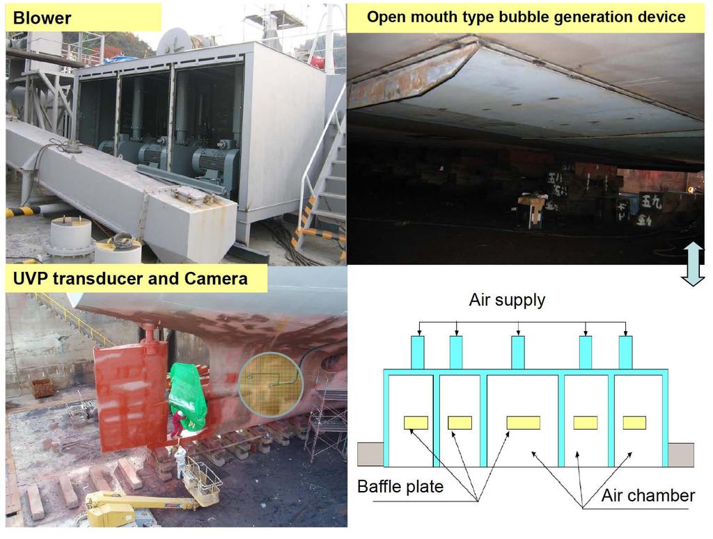
 50 Application of Simulation Technology to Mitsubishi Air Lubrication System CHIHARU KAWAKITA *1 SHINSUKE SATO *2 TAKAHIRO OKIMOTO *2 For the development and design of the Mitsubishi Air Lubrication System
Study on Marine Propeller Running in Bubbly Flow
 Third International Symposium on Marine Propulsors smp 13, Launceston, Tasmania, Australia, May 2013 Study on Marine Propeller Running in Bubbly Flow Chiharu Kawakita Mitsubishi Heavy Industries, Ltd.,
A Study on Roll Damping of Bilge Keels for New Non-Ballast Ship with Rounder Cross Section
 International Ship Stability Workshop 2013 1 A Study on Roll Damping of Bilge Keels for New Non-Ballast Ship with Rounder Cross Section Tatsuya Miyake and Yoshiho Ikeda Department of Marine System Engineering,
Ship Resistance and Propulsion Prof. Dr. P. Krishnankutty Ocean Department Indian Institute of Technology, Madras
 Ship Resistance and Propulsion Prof. Dr. P. Krishnankutty Ocean Department Indian Institute of Technology, Madras Lecture - 6 Bulbous Bow on Ship Resistance Welcome back to the class we have been discussing
Development of TEU Type Mega Container Carrier
 Development of 8 700 TEU Type Mega Container Carrier SAKAGUCHI Katsunori : P. E. Jp, Manager, Ship & Offshore Basic Design Department, IHI Marine United Inc. TOYODA Masanobu : P. E, Jp, Ship & Offshore
Applied Fluid Mechanics
 Applied Fluid Mechanics 1. The Nature of Fluid and the Study of Fluid Mechanics 2. Viscosity of Fluid 3. Pressure Measurement 4. Forces Due to Static Fluid 5. Buoyancy and Stability 6. Flow of Fluid and
Vessel Modification and Hull Maintenance Considerations Options & Pay Back Period or Return On Investments
 Vessel Modification and Hull Maintenance Considerations Options & Pay Back Period or Return On Investments By Dag Friis Christian Knapp Bob McGrath Ocean Engineering Research Centre MUN Engineering 1 Overview:
CERTIFICATES OF COMPETENCY IN THE MERCHANT NAVY MARINE ENGINEER OFFICER
 CERTIFICATES OF COMPETENCY IN THE MERCHANT NAVY MARINE ENGINEER OFFICER EXAMINATIONS ADMINISTERED BY THE SCOTTISH QUALIFICATIONS AUTHORITY ON BEHALF OF THE MARITIME AND COASTGUARD AGENCY STCW 95 CHIEF
The Usage of Propeller Tunnels For Higher Efficiency and Lower Vibration. M. Burak Şamşul
 The Usage of Propeller Tunnels For Higher Efficiency and Lower Vibration M. Burak Şamşul ITU AYOC 2014 - Milper Pervane Teknolojileri Company Profile MILPER is established in 2011 as a Research and Development
Experimental analysis of an air cavity concept applied on a ship hull to improve the hull resistance
 Experimental analysis of an air cavity concept applied on a ship hull to improve the hull resistance Jamie Butterworth 1, Mehmet Atlar 2, Weichao Shi 2 1 Babcock International Group 2 School of Marine
Parasite Drag. by David F. Rogers Copyright c 2005 David F. Rogers. All rights reserved.
 Parasite Drag by David F. Rogers http://www.nar-associates.com Copyright c 2005 David F. Rogers. All rights reserved. How many of you still have a Grimes rotating beacon on both the top and bottom of the
(Refer Slide Time: 2:16)
") Fluid Machines. Professor Sankar Kumar Som. Department Of Mechanical Engineering. Indian Institute Of Technology Kharagpur. Lecture-23. Diffuser and Cavitation. Good morning and welcome you all to this
Fluid Machines. Professor Sankar Kumar Som. Department Of Mechanical Engineering. Indian Institute Of Technology Kharagpur. Lecture-23. Diffuser and Cavitation. Good morning and welcome you all to this
Injector Dynamics Assumptions and their Impact on Predicting Cavitation and Performance
 Injector Dynamics Assumptions and their Impact on Predicting Cavitation and Performance Frank Husmeier, Cummins Fuel Systems Presented by Laz Foley, ANSYS Outline Overview Computational Domain and Boundary
New Vessel Fuel Efficient Design and Construction Considerations Medium and Long-Term Options
 New Vessel Fuel Efficient Design and Construction Considerations Medium and Long-Term Options By Dag Friis Christian Knapp Bob McGrath Ocean Engineering Research Centre MUN Engineering Overview : Introduction
Bioreactor System ERT 314. Sidang /2011
 Bioreactor System ERT 314 Sidang 1 2010/2011 Chapter 2:Types of Bioreactors Week 4 Flow Patterns in Agitated Tanks The flow pattern in an agitated tank depends on the impeller design, the properties of
Technical Bulletin 161. How Deep Can I Design my Aeration Tanks? by:
 Technical Bulletin 161 How Deep Can I Design my Aeration Tanks? by: Environmental Dynamics International Published: 01/2017 BULLETIN BRIEF In the water and wastewater treatment field there are many needs
A STUDY OF THE LOSSES AND INTERACTIONS BETWEEN ONE OR MORE BOW THRUSTERS AND A CATAMARAN HULL
 A STUDY OF THE LOSSES AND INTERACTIONS BETWEEN ONE OR MORE BOW THRUSTERS AND A CATAMARAN HULL L Boddy and T Clarke, Austal Ships, Australia SUMMARY CFD analysis has been conducted on a 100m catamaran hull
UNIT 15 WATER HAMMER AND SURGE TANKS
 UNT 15 WATER HAMMER AND SURGE TANKS Structure 15.1 ntroduction Objectives 15.2 Water Hammer 15.2.1 Expression for Rise in Pressure 15.3 Rapid Acceleration of Flow 15.4 Surge Tanks 15.5 Summary 15.6 Keywords
Summary Introduction
 !"##$% &'!'((!! Summary The EU-project ULYSSES: Ultra Slow Ships is currently in progress. ULYSSES main objective is to develop ship design concepts, which should be able to meet the 2020 and 2050 emissions
IMPROVING PLANT AERATION USING GAS INFUSION TECHNOLOGY
 IMPROVING PLANT AERATION USING GAS INFUSION TECHNOLOGY AERATION IN WASTEWATER Municipal sewer collection systems-odor Mgmt. Lift and transfer stations Lagoons / Retention Ponds BOD / COD treatment Enhanced
Interceptors in theory and practice
 Interceptors in theory and practice An interceptor is a small vertical plate, usually located at the trailing edge on the pressure side of a foil. The effect is a completely different pressure distribution
Computer Simulation Helps Improve Vertical Column Induced Gas Flotation (IGF) System
 System") JOURNAL ARTICLES BY FLUENT SOFTWARE USERS JA187 Computer Simulation Helps Improve Vertical Column Induced Gas Flotation (IGF) System Computer simulation has helped NATCO engineers make dramatic improvements
JOURNAL ARTICLES BY FLUENT SOFTWARE USERS JA187 Computer Simulation Helps Improve Vertical Column Induced Gas Flotation (IGF) System Computer simulation has helped NATCO engineers make dramatic improvements
Greenup Lock Filling and Emptying System Study
 Fourth LACCEI International Latin American and Caribbean Conference for Engineering and Technology (LACCET 2006) Breaking Frontiers and Barriers in Engineering: Education, Research and Practice 21-23 June
DEPARTMENT OF THE NAVY NAVAL UNDERSEA WARFARE CENTER DIVISION NEWPORT
 DEPARTMENT OF THE NAVY NAVAL UNDERSEA WARFARE CENTER DIVISION NEWPORT gsop P OFFICE OF COUNSEL (PATENTS) 14 1176 HOWELL STREET Q w BUILDING 112T, CODE OOOC NEWPORT, RHODE ISLAND 02841-1708 PHONE: 401 832-4736
ANNEX 16 RESOLUTION MEPC.232(65) Adopted on 17 May 2013
 Adopted on 17 May 2013") Annex 16, page 1 ANNEX 16 RESOLUTION MEPC.3(65) Adopted on 17 May 013 013 INTERIM GUIDELINES FOR DETERMING MINIMUM PROPULSION POWER TO MAINTAIN THE MANOEUVRABILITY OF SHIPS IN ADVERSE CONDITIONS THE MARINE
Annex 16, page 1 ANNEX 16 RESOLUTION MEPC.3(65) Adopted on 17 May 013 013 INTERIM GUIDELINES FOR DETERMING MINIMUM PROPULSION POWER TO MAINTAIN THE MANOEUVRABILITY OF SHIPS IN ADVERSE CONDITIONS THE MARINE
Numerical and Experimental Investigation of the Possibility of Forming the Wake Flow of Large Ships by Using the Vortex Generators
 Second International Symposium on Marine Propulsors smp 11, Hamburg, Germany, June 2011 Numerical and Experimental Investigation of the Possibility of Forming the Wake Flow of Large Ships by Using the
ZIN Technologies PHi Engineering Support. PHi-RPT CFD Analysis of Large Bubble Mixing. June 26, 2006
 ZIN Technologies PHi Engineering Support PHi-RPT-0002 CFD Analysis of Large Bubble Mixing Proprietary ZIN Technologies, Inc. For nearly five decades, ZIN Technologies has provided integrated products and
Flow Over Bodies: Drag and Lift
 Fluid Mechanics (0905241) Flow Over Bodies: Drag and Lift Dr.-Eng. Zayed dal-hamamre 1 Content Overview Drag and Lift Flow Past Objects Boundary Layers Laminar Boundary Layers Transitional and Turbulent
COMPUTATIONAL FLOW MODEL OF WESTFALL'S LEADING TAB FLOW CONDITIONER AGM-09-R-08 Rev. B. By Kimbal A. Hall, PE
 COMPUTATIONAL FLOW MODEL OF WESTFALL'S LEADING TAB FLOW CONDITIONER AGM-09-R-08 Rev. B By Kimbal A. Hall, PE Submitted to: WESTFALL MANUFACTURING COMPANY September 2009 ALDEN RESEARCH LABORATORY, INC.
Effect of Fluid Density and Temperature on Discharge Coefficient of Ogee Spillways Using Physical Models
 RESEARCH ARTICLE Effect of Fluid Density and Temperature on Discharge Coefficient of Ogee Spillways Using Physical Models M. SREENIVASULU REDDY 1 DR Y. RAMALINGA REDDY 2 Assistant Professor, School of
Bubble Dynamics in a Vibrating Liquid. By: James Wymer, Jaggar Henzerling, Aaron Kilgallon, Michael McIntire, Mohammed Ghallab
 Bubble Dynamics in a Vibrating Liquid By: James Wymer, Jaggar Henzerling, Aaron Kilgallon, Michael McIntire, Mohammed Ghallab Background In the early 1960 s a series of rocket failures plagued leading
CFD ANALYSIS OF FRICTIONAL DRAG REDUCTION ON THE UNDERNEATH OF SHIP S HULL USING AIR LUBRICATION SYSTEM
 International Journal of Mechanical Engineering and Technology (IJMET) Volume 9, Issue 4, April 2018, pp. 408 416, Article ID: IJMET_09_04_046 Available online at http://www.iaeme.com/ijmet/issues.asp?jtype=ijmet&vtype=9&itype=4
Structure of Mechanically Agitated Gas-Liquid Contactors
 Structure of Mechanically Agitated Gas-Liquid Contactors 5 2 Structure of Mechanically Agitated Gas-Liquid Contactors 2.1 The vessel geometry The most commonly adopted geometry of a stirred gas-liquid
Application of Computational Fluid Dynamics to Compressor Efficiency Improvement
 Purdue University Purdue e-pubs International Compressor Engineering Conference School of Mechanical Engineering 1994 Application of Computational Fluid Dynamics to Compressor Efficiency Improvement J.
Uncontrolled copy not subject to amendment. Principles of Flight
 Uncontrolled copy not subject to amendment Principles of Flight Principles of Flight Learning Outcome 1: Know the principles of lift, weight, thrust and drag and how a balance of forces affects an aeroplane
SECOND ENGINEER REG III/2 NAVAL ARCHITECTURE
 SECOND ENGINEER REG III/2 NAVAL ARCHITECTURE LIST OF TOPICS A B C D E F G H I J Hydrostatics Simpson's Rule Ship Stability Ship Resistance Admiralty Coefficients Fuel Consumption Ship Terminology Ship
External Tank- Drag Reduction Methods and Flow Analysis
 External Tank- Drag Reduction Methods and Flow Analysis Shaik Mohammed Anis M.Tech Student, MLR Institute of Technology, Hyderabad, India. G. Parthasarathy Associate Professor, MLR Institute of Technology,
Project Background and Scope
 Project Background and Scope The purpose of the project is to generate a design that can easily and effectively convert a Laser sailboat to a human powered Flettner ship. A Flettner ship is a ship that
Hysucat. powerful, functional...
 STEALTH 520 patrol Hysucat The HYdrofoil SUpported CATamaran (HYSUCAT) is an integrated design comprising a catamaran hull equipped with a hydrofoil system between the demi-hulls which carries a part of
Software Tool Suite for Bubble Wake Signature of Waterjet Propelled Ships
 LCS-1 "Approved for public release; distribution is unlimited" Software Tool Suite for Bubble Wake Signature of Waterjet Propelled Ships Dynaflow, Inc. 10621-J Iron Bridge Road Jessup, Maryland 20794 Contact:
Hydrostatics and Stability Dr. Hari V Warrior Department of Ocean Engineering and Naval Architecture Indian Institute of Technology, Kharagpur
 Hydrostatics and Stability Dr. Hari V Warrior Department of Ocean Engineering and Naval Architecture Indian Institute of Technology, Kharagpur Module No.# 01 Lecture No. # 01 Introduction Hello everybody.
Energy and mass transfer in gas-liquid reactors.
 Energy and mass transfer in gas-liquid reactors. John M Smith School of Engineering (D2) University of Surrey, Guildford GU2 7XH, UK j.smith@surrey.ac.uk 1 Energy and mass transfer in gas-liquid reactors.
TS 4001: Lecture Summary 4. Resistance
 TS 4001: Lecture Summary 4 Resistance Ship Resistance Very complex problem: Viscous effects. Free surface effects. Can only be solved by a combination of: Theoretical methods. Phenomenological methods.
Computational Analysis of Oil Spill in Shallow Water due to Wave and Tidal Motion Madhu Agrawal Durai Dakshinamoorthy
 Computational Analysis of Oil Spill in Shallow Water due to Wave and Tidal Motion Madhu Agrawal Durai Dakshinamoorthy 1 OUTLINE Overview of Oil Spill & its Impact Technical Challenges for Modeling Review
Write important assumptions used in derivation of Bernoulli s equation. Apart from an airplane wing, give an example based on Bernoulli s principle
 HW#3 Sum07 #1. Answer in 4 to 5 lines in the space provided for each question: (a) A tank partially filled with water has a balloon well below the free surface and anchored to the bottom by a string. The
A COMPUTATIONAL STUDY ON THE DESIGN OF AIRFOILS FOR A FIXED WING MAV AND THE AERODYNAMIC CHARACTERISTIC OF THE VEHICLE
 28 TH INTERNATIONAL CONGRESS OF THE AERONAUTICAL SCIENCES A COMPUTATIONAL STUDY ON THE DESIGN OF AIRFOILS FOR A FIXED WING MAV AND THE AERODYNAMIC CHARACTERISTIC OF THE VEHICLE Jung-Hyun Kim*, Kyu-Hong
SPECIFYING MOTIONLESS MIXERS
 SPECIFYING MOTIONLESS MIXERS The operating cost for the energy necessary to mix fluids with a motionless mixer is usually far lower than for any competitive mixing technique. An extruder which melts, mixes
Static Fluids. **All simulations and videos required for this package can be found on my website, here:
 DP Physics HL Static Fluids **All simulations and videos required for this package can be found on my website, here: http://ismackinsey.weebly.com/fluids-hl.html Fluids are substances that can flow, so
Design, Static Structural & Model Analysis of Water Ring Vacuum Pump Impeller
 IJSRD - International Journal for Scientific Research & Development Vol. 6, Issue 03, 2018 ISSN (online): 2321-0613 Design, Static Structural & Model Analysis of Water Ring Vacuum Pump Impeller Ajay A.
Marine Kit 4 Marine Kit 4 Sail Smooth, Sail Safe
 Marine Kit 4 Marine Kit 4 Sail Smooth, Sail Safe Includes Basic ship Terminologies and Investigation Check list Index 1. Ship Terminology 03 2. Motions of a Floating Body...09 3. Ship Stability.10 4. Free
Caltec. The world leader in Surface Jet Pump (SJP) and compact separation systems for upstream oil and gas production enhancement
 and compact separation systems for upstream oil and gas production enhancement") Caltec brings simple passive technology that enables oil and gas operators to harness the kinetic energy of the production process to enhance their production, extending economic field life and reducing
Caltec brings simple passive technology that enables oil and gas operators to harness the kinetic energy of the production process to enhance their production, extending economic field life and reducing
FLUID MECHANICS Time: 1 hour (ECE-301) Max. Marks :30
 Max. Marks :30") B.Tech. [SEM III(ME&CE)] QUIZ TEST-1 (Session : 2013-14) Time: 1 hour (ECE-301) Max. Marks :30 Note: Attempt all questions. PART A Q1. The velocity of the fluid filling a hollow cylinder of radius 0.1
B.Tech. [SEM III(ME&CE)] QUIZ TEST-1 (Session : 2013-14) Time: 1 hour (ECE-301) Max. Marks :30 Note: Attempt all questions. PART A Q1. The velocity of the fluid filling a hollow cylinder of radius 0.1
The effect of back spin on a table tennis ball moving in a viscous fluid.
 How can planes fly? The phenomenon of lift can be produced in an ideal (non-viscous) fluid by the addition of a free vortex (circulation) around a cylinder in a rectilinear flow stream. This is known as
Drilling Efficiency Utilizing Coriolis Flow Technology
 Session 12: Drilling Efficiency Utilizing Coriolis Flow Technology Clement Cabanayan Emerson Process Management Abstract Continuous, accurate and reliable measurement of drilling fluid volumes and densities
THE PERFORMANCE OF PLANING HULLS IN TRANSITION SPEEDS
 THE PERFORMANCE OF PLANING HULLS IN TRANSITION SPEEDS BY DOYOON KIM UNIVERSITY OF SOUTHAMPTON LIST OF CONTENTS AIM & OBJECTIVE HYDRODYNAMIC PHENOMENA OF PLANING HULLS TOWING TANK TEST RESULTS COMPUTATIONAL
Workshop 1: Bubbly Flow in a Rectangular Bubble Column. Multiphase Flow Modeling In ANSYS CFX Release ANSYS, Inc. WS1-1 Release 14.
 Workshop 1: Bubbly Flow in a Rectangular Bubble Column 14. 5 Release Multiphase Flow Modeling In ANSYS CFX 2013 ANSYS, Inc. WS1-1 Release 14.5 Introduction This workshop models the dispersion of air bubbles
ANSWERS TO QUESTIONS IN THE NOTES AUTUMN 2018
 ANSWERS TO QUESTIONS IN THE NOTES AUTUMN 2018 Section 1.2 Example. The discharge in a channel with bottom width 3 m is 12 m 3 s 1. If Manning s n is 0.013 m -1/3 s and the streamwise slope is 1 in 200,
Application Worksheet
 Application Worksheet All dimensions are nominal. Dimensions in [ ] are in millimeters. Service Conditions Medium Through Valve: Required C v : Temperature Maximum: Minimum: Normal: Flow Maximum: Minimum:
3. Observed initial growth of short waves from radar measurements in tanks (Larson and Wright, 1975). The dependence of the exponential amplification
. The dependence of the exponential amplification") Geophysica (1997), 33(2), 9-14 Laboratory Measurements of Stress Modulation by Wave Groups M.G. Skafel and M.A. Donelan* National Water Research Institute Canada Centre for Inland Waters Burlington, Ontario,
Geophysica (1997), 33(2), 9-14 Laboratory Measurements of Stress Modulation by Wave Groups M.G. Skafel and M.A. Donelan* National Water Research Institute Canada Centre for Inland Waters Burlington, Ontario,
Tidal streams and tidal stream energy device design
 Tidal streams and tidal stream energy device design This technical article introduces fundamental characteristics of tidal streams and links these to the power production of tidal stream energy devices.
AIRFLOW GENERATION IN A TUNNEL USING A SACCARDO VENTILATION SYSTEM AGAINST THE BUOYANCY EFFECT PRODUCED BY A FIRE
 - 247 - AIRFLOW GENERATION IN A TUNNEL USING A SACCARDO VENTILATION SYSTEM AGAINST THE BUOYANCY EFFECT PRODUCED BY A FIRE J D Castro a, C W Pope a and R D Matthews b a Mott MacDonald Ltd, St Anne House,
4 ALBERT EMBANKMENT LONDON SE1 7SR Telephone: +44 (0) Fax: +44 (0)
 Fax: +44 (0)") E 4 ALBERT EMBANKMENT LONDON SE1 7SR Telephone: +44 (0)0 7735 7611 Fax: +44 (0)0 7587 310 MEPC.1/Circ.850/Rev.1 15 July 015 013 INTERIM GUIDELINES FOR DETERMINING MINIMUM PROPULSION POWER TO MAINTAIN THE
E 4 ALBERT EMBANKMENT LONDON SE1 7SR Telephone: +44 (0)0 7735 7611 Fax: +44 (0)0 7587 310 MEPC.1/Circ.850/Rev.1 15 July 015 013 INTERIM GUIDELINES FOR DETERMINING MINIMUM PROPULSION POWER TO MAINTAIN THE
INTERIM GUIDELINES FOR DETERMINING MINIMUM PROPULSION POWER TO MAINTAIN THE MANOEUVRABILITY OF SHIPS IN ADVERSE CONDITIONS
 E 4 ALBERT EMBANKMENT LONDON SE1 7SR Telephone: +44 (0)20 7735 7611 Fax: +44 (0)20 7587 3210 MSC-MEPC.2/Circ.11 3 December 2012 INTERIM GUIDELINES FOR DETERMINING MINIMUM PROPULSION POWER TO MAINTAIN THE
An underwater explosion is an explosion where the point of detonation is below the surface of the water.
 Underwater Explosion 1 Introduction An underwater explosion is an explosion where the point of detonation is below the surface of the water. Underwater explosion are categorized in accordance with their
ACTIVITY 1: Buoyancy Problems. OBJECTIVE: Practice and Reinforce concepts related to Fluid Pressure, primarily Buoyancy
 LESSON PLAN: SNAP, CRACKLE, POP: Submarine Buoyancy, Compression, and Rotational Equilibrium DEVELOPED BY: Bill Sanford, Nansemond Suffolk Academy 2012 NAVAL HISTORICAL FOUNDATION TEACHER FELLOWSHIP ACTIVITY
Experience and Future Potential of the Oblique Icebreaker
 SHIP Design & Engineering CONSULTING & Project Development ICE MODEL & Full Scale Testing OFFSHORE Development Experience and Future Potential of the Oblique Icebreaker Mika Hovilainen Project Manager
Thin Film Slot Coating in a Rarefied Low Viscosity Gas
 www.bradford.ac.uk Thin Film Slot Coating in a Rarefied Low Viscosity Gas H. Benkreira & J.B. Ikin* School of Engineering, Design & Technology University of Bradford-UK *Multicoat Ltd., 21 Turnfield Road,
Ship Resistance and Propulsion Prof. Dr. P. Krishnankutty Ocean Department Indian Institute of Technology, Madras
 Ship Resistance and Propulsion Prof. Dr. P. Krishnankutty Ocean Department Indian Institute of Technology, Madras Lecture - 7 Air and Wind Resistance Dimensional Analysis I Coming back to the class, we
Aerodynamic Analysis of Blended Winglet for Low Speed Aircraft
 , July 1-3, 2015, London, U.K. Aerodynamic Analysis of Blended Winglet for Low Speed Aircraft Pooja Pragati, Sudarsan Baskar Abstract This paper provides a practical design of a new concept of massive
Propellers and propulsion
 Propellers and propulsion Kul-24.3200 Introduction of Marine Hydrodynamics Aalto University 25/10/2015 Introduction of Marine Hydrodynamics 1 Content of the course Resistance Propulsion Introduction, Momentum
HULL VANE VERSUS LENGTHENING A comparison between four alternatives for a 61m OPV
 HULL VANE VERSUS LENGTHENING A comparison between four alternatives for a 61m OPV N. Hagemeister (van Oossanen Fluid Dynamics), n.hagemeister@oossanen.nl K. Uithof (Hull Vane B.V.), k.uithof@hullvane.com
Effect of Co-Flow Jet over an Airfoil: Numerical Approach
 Contemporary Engineering Sciences, Vol. 7, 2014, no. 17, 845-851 HIKARI Ltd, www.m-hikari.com http://dx.doi.org/10.12988/ces.2014.4655 Effect of Co-Flow Jet over an Airfoil: Numerical Approach Md. Riajun
Numerical analysis of influence of streamline rudder on screw propeller efficiency
 POLISH MARITIME RESEARCH 2(65) 2010 Vol 17; pp. 18-22 10.2478/v10012-010-0013-4 Numerical analysis of influence of streamline rudder on screw efficiency Tomasz Abramowski, Ph. D. akub Handke, M. Sc. Tadeusz
Development of Technology to Estimate the Flow Field around Ship Hull Considering Wave Making and Propeller Rotating Effects
 Development of Technology to Estimate the Flow Field around Ship Hull Considering Wave Making and Propeller Rotating Effects 53 MAKOTO KAWABUCHI *1 MASAYA KUBOTA *1 SATORU ISHIKAWA *2 As can be seen from
IMO MEPC.1/Circ.833: Guidelines for the Reduction of Underwater Noise from Commercial Shipping to Address Adverse Impacts on Marine Life
 21 st ASCOBANS Advisory Committee Meeting AC21/Inf.3.2.1 (WG) Gothenburg, Sweden, 29 September - 1 October 2014 Dist. 30 July 2014 Agenda Item 3.2.1 Review of New Information on Threats to Small Cetaceans
How Does A Wind Turbine's Energy Production Differ from Its Power Production? 1
 Siting Wind Power: Wind Power Curves & Community Considerations (Teacher Notes) (Assessing the Feasibility of Wind Power for Pennsylvania) Notes on Part 1 A Beaufort scale is included on the next page
The below identified patent application is available for licensing. Requests for information should be addressed to:
 DEPARTMENT OF THE NAVY OFFICE OF COUNSEL NAVAL UNDERSEA WARFARE CENTER DIVISION 1176 HOWELL STREET NEWPORT Rl 02841-1708 IN REPLY REFER TO Attorney Docket No. 300170 20 March 2018 The below identified
Numerical Simulation And Aerodynamic Performance Comparison Between Seagull Aerofoil and NACA 4412 Aerofoil under Low-Reynolds 1
 Advances in Natural Science Vol. 3, No. 2, 2010, pp. 244-20 www.cscanada.net ISSN 171-7862 [PRINT] ISSN 171-7870 [ONLINE] www.cscanada.org *The 3rd International Conference of Bionic Engineering* Numerical
The Estimation Of Compressor Performance Using A Theoretical Analysis Of The Gas Flow Through the Muffler Combined With Valve Motion
 Purdue University Purdue e-pubs International Compressor Engineering Conference School of Mechanical Engineering The Estimation Of Compressor Performance Using A Theoretical Analysis Of The Gas Flow Through
Basic Fluid Mechanics
 Basic Fluid Mechanics Chapter 7B: Forces on Submerged Bodies 7/26/2018 C7B: Forces on Submerged Bodies 1 Forces on Submerged Bodies Lift and Drag are forces exerted on an immersed body by the surrounding
Bubble Coalescence and Breakup in Gas-Liquid Stirred Tank Reactors
 Bubble Coalescence and Breakup in Gas-Liquid Stirred Tank Reactors Rahman Sudiyo Background Stirred tank reactors are widely used in chemical, pharmaceutical and biochemical industries. Mass transfer between
ITTC Recommended Procedures and Guidelines
 7.5- -- Page 1 of 6 Table of Contents 1 PURPOSE OF PROCEDURE 2 2 PARAMETERS...2 2.1 Definition of Variables...2 3 DESCRIPTION OF PROCEDURE...2 3.1...2 3.1.1 Hull Model...2 3.1.2 Propeller Model...3 3.1.3
Performance Improvements in Boeing/AFOSR Mach 6 Quiet Wind Tunnel Based on CFD Predictions
 Performance Improvements in Boeing/AFOSR Mach 6 Quiet Wind Tunnel Based on CFD Predictions Hadassah Naiman, Doyle D. Knight Rutgers University Selin Aradag US Air Force Academy Thomas J. Juliano,, Steven
13.012: Hydrodynamics for Ocean Engineers
 13.012: Hydrodynamics for Ocean Engineers Alexandra H. Techet Dept. of Ocean Engineering 9 September 2004 Lecture 1 What is Hydrodynamics? Hydrodynamics v. Aerodynamics Water is almost 1000 times denser
What is Hydrodynamics?
 13.012: Hydrodynamics for Ocean Engineers Alexandra H. Techet Dept. of Ocean Engineering 9 September 2004 Lecture 1 What is Hydrodynamics? Hydrodynamics v. Aerodynamics Water is almost 1000 times denser
Courses of Instruction: Controlling and Monitoring of Pipelines
 Courses of Instruction: Controlling and Monitoring of Pipelines Date December 2010 Dr. Peter Eschenbacher Partner Angergraben 4 85250 Altomünster Germany Tel. +49-(0)8254 / 99 69 57 Fax +49-(0)8254 / 99
ABS. Acoustic Bubble Spectrometer. Measurement of Bubble Size, Bubble Number & Void Fraction DYNAFLOW, INC. Research & Development in Applied Sciences
 ABS Acoustic Bubble Spectrometer Measurement of Bubble Size, Bubble Number & Void Fraction DYNAFLOW, INC. Research & Development in Applied Sciences DYNAFLOW, INC. The ABS Advantage 56789012345678901256789012345
MODELING OF THERMAL BEHAVIOR INSIDE A BUBBLE
 CAV2001:sessionB6.002 1 MODEING OF THERMA BEHAVIOR INSIDE A BUBBE Boonchai ERTNUWAT *, Kazuyasu SUGIYAMA ** and Yoichiro MATSUMOTO *** *, ***Dept. of Mechanical Engineering, The University of Tokyo, Tokyo,
THEORETICAL EVALUATION OF FLOW THROUGH CENTRIFUGAL COMPRESSOR STAGE
 THEORETICAL EVALUATION OF FLOW THROUGH CENTRIFUGAL COMPRESSOR STAGE S.Ramamurthy 1, R.Rajendran 1, R. S. Dileep Kumar 2 1 Scientist, Propulsion Division, National Aerospace Laboratories, Bangalore-560017,ramamurthy_srm@yahoo.com
Ship waves in Tallinn Bay: Experimental and numerical study
 Ship waves in Tallinn Bay: Experimental and numerical study Tomas Torsvik Bergen Center for Computational Science UNIFOB AS In collaboration with Tarmo Soomere Wave Engineering Centre for Nonlinear studies
2.016: Hydrodynamics
 2.016: Hydrodynamics Alexandra H. Techet Dept. of Mechanical Engineering Lecture 1 What is Hydrodynamics? Hydrodynamics v. Aerodynamics Water is almost 1000 times denser than air! Marine Hydrodynamics
Conventional Ship Testing
 Conventional Ship Testing Experimental Methods in Marine Hydrodynamics Lecture in week 34 Chapter 6 in the lecture notes 1 Conventional Ship Testing - Topics: Resistance tests Propeller open water tests
Volume 2, Issue 5, May- 2015, Impact Factor: Structural Analysis of Formula One Racing Car
 Structural Analysis of Formula One Racing Car Triya Nanalal Vadgama 1, Mr. Arpit Patel 2, Dr. Dipali Thakkar 3, Mr. Jignesh Vala 4 Department of Aeronautical Engineering, Sardar Vallabhbhai Patel Institute
An Impeller Blade Analysis of Centrifugal Gas Compressor Using CFD
 An Impeller Blade Analysis of Centrifugal Gas Compressor Using CFD Vivek V. Kulkarni Department of Mechanical Engineering KLS Gogte Institute of Technology, Belagavi, Karnataka Dr. Anil T.R. Department
STUDY OF MICROBUBBLES FOR SKIN-FRICTION DRAG REDUCTION. *
 STUDY OF MICROBUBBLES FOR SKIN-FRICTION DRAG REDUCTION Yan Yao 1 *, Jin-ling Luo 1,Kun Zhu 1, Hai-bo He 1, Rui Wu 2, Shi-jie Qin 3 1 Beijing Electromechanic Engineering Institute, Beijing, 100074, China
Acoustic Emission Testing of The Shell 0f Electromagnetic Valve
 17th World Conference on Nondestructive Testing, 25-28 Oct 2008, Shanghai, China Acoustic Emission Testing of The Shell 0f Electromagnetic Valve guozhen XU 1, yiwei CHEN 1, zhihua CAO 2 ABSTRACT Shanghai
Three New Concepts of Multi-Hulls
 Three New Concepts of Multi-Hulls Victor A. Dubrovsky Independent designer, Russian Federation 114-71 Budapeshtskaja Str, St.Petersburg, 192283, Russian Federation Multi-hulls@yandex.ru Abstract Many multi-hull
Development of High-speed Gas Dissolution Device
 Development of High-speed Gas Dissolution Device Yoichi Nakano*, Atsushi Suehiro**, Tetsuhiko Fujisato***, Jun Ma**** Kesayoshi Hadano****, Masayuki Fukagawa***** *Ube National College of Technology, Tokiwadai
AERODYNAMIC CHARACTERISTICS OF NACA 0012 AIRFOIL SECTION AT DIFFERENT ANGLES OF ATTACK
 AERODYNAMIC CHARACTERISTICS OF NACA 0012 AIRFOIL SECTION AT DIFFERENT ANGLES OF ATTACK SUPREETH NARASIMHAMURTHY GRADUATE STUDENT 1327291 Table of Contents 1) Introduction...1 2) Methodology.3 3) Results...5