COMPRESSED AIR SYSTEM OPTIMIZATION EXPERT TRAINING
|
|
|
- Damon Gray
- 5 years ago
- Views:
Transcription

1 COMPRESSED AIR SYSTEM OPTIMIZATION EXPERT TRAINING


2 Introduction to Compressed Air 1 1. Introduction to Compressed Air Systems Compressed air has 3 primary uses Power As an energy source to perform work Process Air becomes part of a process Control To stop, start or regulate the operation of a machine 2 1


3 1. Introduction to Compressed Air Systems A compressed air system includes both the supply side components and the demand side components Introduction to Compressed Air Systems Old Management Technique Plant production is #1 priority Plant compressed air system must always be maintained Over supply of compressed air is acceptable, under supply is not acceptable Minimum i pressure must be maintained. Higher pressure is acceptable New Management Technique Plant productivity is the #1 priority The plant air demand must always be supplied The compressed air system must be in balance with demand. Both over supply and under supply are unacceptable Compressed air pressure must tbe stable. Pressures higher than required are unacceptable as are pressures lower than required. 4 2


4 Compressed Air System Optimisation Defined There are three basic ways to optimise the consumption of a compressed air system: 1. Produce compressed air more efficiently 2. Consume less compressed air 3. Utilise the heat of compression Source: ASME EA-4 5 Compressed Air System Efficiency Fact: Compressed air is an inefficient source of energy and should be used wisely. Consider this: An air motor with 0,68 kw shaft output consumes 50 m 3 /hr An air compressor consumes about 5.6 kw to produce 50 m 3 /hr at 7 bar, or 8 times as much! 6 3
5 8 Compressed Air System Efficiency hp Power Losses on Supply and Demand Sides (including heat of compression losses) 0 Input Power to Electric Motor Shaft Power Required by Compressor Useful Work Power Losses and Useful Work Source: Compressed Air Challenge Compressed Air System Cost Compressed air power is costly The 0,68 kw compressed air motor shaft output costs RM per year at hours operation. An electric motor with a similar shaft output would consume about 0,85 kw and cost RM per year to operate. 8 4


6 Compressed Air System Costs System losses further increase the costs: Typically 35 to 45% of compressed air is wasted to leakage and artificial demand before it gets to the user. And 10%+ may be wasted through inappropriate uses. Artificial Demand 10-15% Leaks 25-30% Inappropriate p Uses 5-10% Production 50% 9 Compressed Air System Costs System losses further increase the costs: Pressure differentials typically reduce end use pressure by 1 or 2 bar forcing discharge pressures higher. Compressor power increases 6 to 7% per unit output for every bar increase. 10 5
7 Compressed Air System Costs System losses further increase the costs: Air compressors often do not run at full efficiency due to poor control and lack of storage receiver capacity Per cen nt kw Input Per cent Capacity 11 The Systems Approach Application of a systems approach to a compressed air system assessment and resulting energy measures directs the focus towards total system performance rather than individual component efficiency Understand compressed air point of use as it supports critical plant production functions Correct existing poor performing applications and those that upset system operation Eliminate i wasteful practices, leaks, artificial i demand, d and inappropriate use Create and maintain an energy balance between supply and demand Optimize compressed air energy storage and air compressor control Source: ASME EA

8 Life Cycle Costs Typically over 75% of the lifetime costs of compressed air are energy related Source: Compressed Air Challenge Based on 30 cen per kwh blended rate 55 kw fully loaded compressor at 4200 hours over ten years. 13 Typical Compressor Operating Cost Item: Typical 160 kw air cooled screw compressor Duty: Full load at 7.5 bar, hours per year Rate: 30 cen per kwh blended Power at full load: Flow: Specific Power: kw 505 l/sec 36.1 kw/ 100l/s Energy Cost = kw x hours x rate Energy Cost = RM per year Purchase Price = RM
9 Comparing Energy Usage and Efficiency 15 Compressed Air System Comparisons Three 160 kw compressed air systems are being evaluated in an existing plant : 1. Existing fixed speed air cooled load/unload compressor, standard refrigerated dryer, standard filter and small receiver 2. A new fixed speed load/unload compressor, new refrigerated dryer, oversized filter and large receiver 3. A VSD compressor, cycling refrigerated dryer, oversized filter and medium receiver 16 8
10 Compressed Air System Comparisons Air cooled compressor, 8 bar hour operation, peak flow 330 l/s, average flow 175 l/s, cost 0,3 cen per kwh Option 1 Existing unit Base Case Ave Compressor Power = 134,5 kw Dryer Power = 6,0 kw Total Energy = kwh Specific Power = 80,3 kw/100 l/s Electrical Cost = RM Compressed Air System Comparisons Air cooled compressor, 7 bar hour operation, peak flow 268 l/s, average flow 133 l /s, cost 0,3 cen per kwh Option 2 New more efficient load/unload, larger storage, lower pressure, cycling refrigerated dryer, leak reduction Ave Compressor Power = 85,1 kw Dryer Power = 1,7 kw Total Energy = Specific Power = 65,3 kw/100 l/s Electrical Cost = RM Saved = RM or 38% Project Cost = RM
11 Compressed Air System Comparisons Air cooled compressor, 7 bar hour operation, peak flow 268 l/s, average flow 133 l /s, cost 0,3 cen per kwh Option 3 New VSD unit, medium storage, lower pressure, cycling refrigerated dryer, leak reduction Ave Compressor Power = 46,0 kw Dryer Power = 1,7 kw Total Energy = kwh Specific Power = 35.9 kw/100 l/s Cost = RM Saved = RM or 66% Project Cost = RM Compressed Air System Payback Option Project Savings Payback Cost O1 - Base O2 - New load/unload RM RM O3 - New VSD RM RM


12 Compressed Air System Incremental Payback Option Project Savings Payback Incremental Cost Years O1 - Base RM O2 - New load/unload RM RM O3 - New VSD RM RM If the required pressure is 5.5 bar Operating at 7 bar creates 2.8 m3/min of artificial demand 20% of the air that is supplied to the system is wasted. Artificial Demand 22 11
13 1. Introduction to Compressed Air Systems Finding leaks soap connections locate source of noise ultra-sound device Example: hole diameter: 3 mm air loss: 0.5 m 3 /min (6 bar gauge) 05m /min x 60 min/h = 30 m 3 /h 30 m 3 /h x 8000 h/year = 240,000 m 3 /year 240,000 m 3 /year x cost/m 3 =???? Introduction to Compressed Air Systems Leakage losses Hole diameter 1 mm 2 mm 4 mm 6mm Air consumption at 6 bar (g) m 3 /min Loss kw mm At RM 0.30/kWh, a 6 mm leak costs over RM 35,478 /year in power plus additional service on the compressed air equipment. Class exercise: Calculate the cost over 4,000 hours
14 1. Introduction to Compressed Air Systems Leakage losses Hole diameter Air consumption at 6 bar (g) m 3 /min Loss kw At RM 0.30/kWh, a 6 mm leak costs over RM 35,478 /year in power plus additional service 1 mm 2 mm 4 mm 6mm air equipment. on the compressed Class exercise: Calculate the cost over 4,000 hours kw x 4,000 x 0.30 = RM 16,200 Question: How much if at 7 bar? Introduction to Compressed Air Systems Leakage losses Hole diameter Air consumption at 6 bar (g) m 3 /min Loss kw At RM 0.30/kWh, a 6 mm leak costs over RM 35,478 /year in power plus additional service 1 mm 2 mm 4 mm 6mm air equipment. on the compressed Class exercise: Calculate the cost over 4,000 hours kw x 1.06 x 4,000 x 0.30 = RM 17,170 Question: If this leak was repaired how much would be saved? 26 13
 T x 1.")
 V L = Leakage volume V R = Receiver volume P I = Initial receiver pressure P F")

15 1. Introduction to Compressed Air Systems Measuring leakage losses by exhausting an air receiver V L = V R x ( p I -p F ) T x 1.25 Feed pipe shut off Leakage volume (tools not in use!) V L = Leakage volume V R = Receiver volume P I = Initial receiver pressure P F = Final receiver pressure T = Measuring period Example: V R = 500 litres p I = 9 barg p F = 4.5 barg T = 30 sec V L = 500 l x ( ) 30 sec Leakage losses in the compressed air system: 94 l/s = 75 x 1.25 = 94 l/s
16 1. Introduction to Compressed Air Systems Measuring leak losses by measuring loaded time of the compressor with end users shut off Pressure gauge reading (bar(g)) T V L = Leakage volume in m 3 /min V C = Compressor volumetric flow rate in m 3 /min t = Time units during which the compressor ran on load T = Total time of the measurement procedure Example: Volumetric compressor flow rate V = 3 m 3 /min Compressor time on load t =t 1 +t 2 +t 3 +t 4 +t 5 = 120 sec Total measurement time T = 600 sec Time c 3 x = 0.6 m 3 /min = 20% Introduction to Compressed Air Systems Leak measurement of the consumers In factories where a large number of air tools, machines and equipment are used, hose connectors and valves often cause considerable leak losses. Using the two methods described previously, two measurements are carried out: A B Tools, machines and equipment are connected for normal operation (total leakage) The shut-off valves upstream of the connectors of the consumers are closed (air distribution leakage) The difference between A and B represents the losses in the pneumatic tools, etc. and their fittings
17 Key Learning Points Compressed air is a necessary utility for industrial plants. For some production uses compressed is a process variable. Many systems waste 50% of more of the compressed air that is consumed. System management must focus on productivity rather than traditional goals. The Systems Approach is an integrated approach, not component efficiency. Generating compressed air is an inefficient energy conversion. 31 Key Learning Points Using air only when other alternatives at es are not available. Eliminating inappropriate uses of compressed air. Reducing delivered pressure to the system eliminates Artificial Demand. Reducing the amount of leakage loss in the system. Minimize Irrecoverable Pressure Loss. Operating compressed air systems at the lowest practical pressure. Optimize compressor control with a properly implemented control strategy
18 For more information: Wayne Perry Technical Director Kaeser Compressors P.O Box 946 Fredericksburg, VA USA Tom Taranto President Data Power Services 8417 Oswego Road PMB-236 Baldwinsville, NY USA
19 2. Understanding Compressed Air 1 2. Understanding Compressed Air What is compressed air? Compressed air is compressed atmospheric air... a mixture of gases... compressible... an energy carrier Air center air main air treatment grid system user Power station transformer user Proportional relationship between pressure, temperature and volume: still valid: 2 1
20 2. Understanding Compressed Air Basic units m = Meter s = Second kg = Kilogram A = Ampere K = Kelvin mol = Molar mass Derived units N = Newton Pa = Pascal bar = Bar = Ohm J = Joule W = Watt C = Celsius Hz = Hertz 3 2. Understanding Compressed Air Physical laws COMPRESSED AIR is atmospheric air under pressure. That means energy is stored in the air. When the compressed air expands again this energy is released as WORK. pressure (energy) WORK EXPANSION 4 2
21 2. Understanding Compressed Air Components of air oxygen 21% other gasses 1% nitrogen 78% 5 2. Understanding Compressed Air Atmospheric pressure......is generated by the weight of the atmosphere. It is dependent on the DENSITY of the air and the height: The normal atmospheric pressure at sea level is bar (760 mmhg (Torr)) 6 3
22 2. Understanding Compressed Air Absolute pressure is the pressure measured from absolute zero. It is used for all theoretical calculations and is required in vacuum and blower applications. Gauge pressure is the practical reference pressure and is based on atmospheric pressure. p amb atmospheric pressure absolute pressure vacuum (g) (g) (g) (g) gauge pressure P g 100% vacuum 0% 7 2. Understanding Compressed Air Definition of pressures Generally: Pressure (p) = Dimensions: 1 Pascal (Pa) = Force (F) Area (A) 1 Newton (N) 1 m² (A) 10 5 Pa = 1 bar Equivalents 1MP MPa = 10 bar 1 hpa = bar Gauge pressure 1 bar = 14.5 psi(g) 1 bar = mmwc 1 bar = Torr A = 1 m 2 8 4
23 2. Understanding Compressed Air Volume ambient air pressure 1 bar (a) 7 m³ atmospheric air volume working pressure 7 bar (a) = 6 bar (g) 1 working m³ 9 2. Understanding Compressed Air Volume Expansion: Working pressure p 1, V 1 Ambient air pressure p 0, V 0 Working pressure 7 bar (a) = 6 bar (g) The volume of atmospheric air decreases at an inverse ratio to the respective absolute pressures (at constant temperature, V p without taking humidity into account) 1 V 1 0 p
24 2. Understanding Compressed Air Definition of volumes Temperature Pressure Relative humidity Density Volume according to DIN 1343 (normal physical state) 0 C = K bar 0% kg/m³ Volume according to DIN/ISO C = K bar 0% kg/m³ Volume related to atmosphere (normal state) atmospheric atmospheric atmospheric temperature pressure humidity variable Volume related to operating state working temperature working pressure variable variable Understanding Compressed Air Conversion of normal volume to volume according to DIN 1343 VN = V I x T N x (p I -(H rel x p D )) p N x T I V N = Normal volume to DIN 1343 V I = Volume at inlet conditions T N = Temperature to DIN 1343, T N = K T I = Maximum temperature at the installation in K p N = Air pressure to DIN 1343, p N = bar p I = Lowest air pressure at the installation in bar H rel = Maximum relative humidity in the air at the installation p D = Saturation pressure of the water vapor contained in the air in bar, dependent on the temperature of the air 12 6
25 2. Understanding Compressed Air Extract from the table for the saturation pressure of water vapour at saturation Saturation pressure p D (bar) at air temperature t ( C) Understanding Compressed Air Gas laws Boyle s Law Isotherms (constant temperature) If the volume is reduced under constant temperature, the pressure increases. P 0 V0 P1 V1 Heat dissipation 14 7
26 2. Understanding Compressed Air Isotherms (constant temperature) p Heat dissipation 1 p 1 T 0 = T 1 p 0 0 V dv 1 V 0 V Understanding Compressed Air Gas laws Charles Law Isobars ( constant pressure ) If heat is applied under constant pressure, The air volume behaves directly proportional to its absolute temperature. V T 0 0 V T 1 1 Application of heat 16 8
27 2. Understanding Compressed Air Isobars (constant pressure) p p 0 = p 1 Application of heat p 0 = p T 1 T 0 V 0 dv V 1 V Understanding Compressed Air Gas laws Amonton s Law Isochors (constant volume) If heat is applied with constant volume, the pressure behaves directly proportional to the absolute temperature. P0 T 0 P 1 T 1 Application of heat 18 9
28 2. Understanding Compressed Air Isochors (constant volume) p p 1 V 0 =V 1 1 T 1 p 0 0 T 0 V 0 =V 1 V Application of heat Understanding Compressed Air Adiabatic or Isentropic (no heat transfer) If the volume is reduced d and heat cannot be dissipated, i d temperature increases with the pressure Heat insulation p p 1 1 p p p 0 0 V 1 dv V 0 T 0 T 1 V 20 10
29 2. Understanding Compressed Air Gas equation p0 x V0 T0 Gas law relating to a closed system: p1 x V1 = = R = constant T1 p = pressure (bar (absolute)) V = volume (m 3 ) T = temperature (K) R = special gas constants bar m³ e.g. R = K = for dry air J kg K Understanding Compressed Air Flow velocity in air lines A 1 v 1 A 2 v 2 valid is: A1 v2 V = A1 x v1 = A2 x v2 V = flow volume v = velocity A = pipe sectional area A2 = v
30 2. Understanding Compressed Air Flow profile pipe wall border layer flow velocity Understanding Compressed Air Flow types We differentiate between: laminar (even) and turbulent (swirling) flow 24 12
31 2. Understanding Compressed Air Straight-line graph for determining inside pipe diameter (steps 1 to 8) Pipe length in m Free air delivery m³/h - m³/min 1 Inside pipe dia. (mm) Systempressure bar (g) Pressure losses bar Understanding Compressed Air Compressed air in motion Pressure loss is dependent on: sectional area velocity pipe length internal surface area of the pipe Pressure (b bar) length (m) 26 13
32 2. Understanding Compressed Air Pressure drop... Performance... is caused by: Working press. bar (g) % kw high flow velocities turbulence internal friction (molecules) friction on the pipe walls Pressure drop lowers the performance of the consumers, increases the cost of compressed air generation and thus production too! Performance loss caused by pressure drop Understanding Compressed Air Minimum diameters of pipes FAD m 3 /min working pressure 7.5 bar (g) length of pipeline up to 50 m up to 100 m up to 200 m over 200 m up to 12.5 up to 15,0 up to 17.5 up to /2" 2 1/2" 2 1/2" 3" 2 1/2" 2 1/2" 3" 3" 3" 3" DN100 DN100 see straightline graph up to " DN100 DN100 up to " DN100 DN100 up to 40.0 DN100 DN100 DN
33 2. Understanding Compressed Air Flow resistance of fittings expressed in equivalent pipe lengths fitting example equivalent pipe length in m pipe inside diameter in mm ,3 0,5 0,6 1 1,3 1,6 1,9 Total pipe length: L overall = L straight + L equivalent or roughly: L overall = 1,6 x L straight Understanding Compressed Air Pressure drop If the normal working pressure of a pneumatic tool is 6 bar (g), any increase above that pressure costs money. Example: V = 30 m 3 /min demand at 7 bar (g) 160 kw At 8 bar (g) approximately 6% more power is required, i.e. around 9.4 kw more Costs: 9.4 kw x 0.05 $/kwh x 4000 h/year = 1880 $/year (13,160 ZAR)! Air main: On a well designed air piping system a pressure drop of 0.1 bar is normally expected. The maximum pressure drop in the air piping system should be no more than 1.5 % of the working pressure 30 15
34 2. Understanding Compressed Air Pressure drop 1. Main piping 0.03 bar 2. Loop main (distribution) 0.03 bar 3. Connecting lines 0.04 bar 4. Refrigeration dryer 0.2 bar 5. FRL unit and hose 0.5 bar 2 max. 0.8 bar Overall pressure drop 0.8 bar Max. pressure at compressor 7.0 bar (g) Pressure at consumer 6.0 bar (g) Difference 1.0 bar Understanding Compressed Air The right fittings G C E A B F A. Valve (we recommend ball valves) B. Filter (separation of water and rust) C. Regulator (constant working pressure) D. Lubricator (mostly oil mist lubricators) E. Quick release couplings (flexibility at the workplace) F. Hose (length: 3-5 m) G. Tool balancer (reduction of work effort) 32 16
35 2. Understanding Compressed Air Points to be observed when sizing and choosing air system piping: Cross-section of the pipe Air consumption Length of the pp piping Working pressure Pressure drop Flow resistance Understanding Compressed Air Points tstobeobseto observed edwhen sizing gand choosing air system piping: Pipe layout Loop/spur main Connecting lines Dead-end lines Pipe connections Fittings 34 17
36 2. Understanding Compressed Air Points to be observed when sizing and choosing air system piping: Fittings and connections Types of outlets Shut-off valves Stopcocks Condensate separators Lubricators Particulate filters Oil filters Regulators Hoses Couplings Understanding Compressed Air Points to be observed when sizing and choosing air system piping: Choice of materials Environmental conditions (humidity, temperature, chemical pollution of the air) Quality of the air (moisture content, oil content, temperature) Costs Expected working life 36 18

37 2. Understanding Compressed Air Uncontrolled Storage: Without t Pressure Differential Quiet zone Moisture separator Protects downstream equipment from oil slugs Prevents compressor from excessive cycling Air In 9.5 bar Air Out 9.5 bar No Real Storage Understanding Compressed Air Uncontrolled pressure and flow 4, Flow (scfm) 3,500 3,000 2,500 2,000 1,500 1, Pressure (psig) 04:26: :01: :36: :11: :46: :21: :56: :31: :06: :41: :19: :54: :29: :04: :39: :14: :49: :24: :59:31.00 Time 15:34: :09: :44: :19: :54: :29: :04: :39: :14: :49: :24: :59: :34: :09: :44:31.00 Pressure Flow Average Flow 38 19

38 2. Understanding Compressed Air Controlled Storage: With Pressure Differential Air In Quiet zone Moisture separator 9.5 bar Protects downstream equipment from oil slugs Prevents compressor from excessive cycling PLUS 6 m 3 of useable air in storage! 3 m 3 Flow Controller 6 m 3 Useable Storage! Air Out 75b 7.5 bar Pressure Differential Creates Stored Energy! 39 Flow 2. Understanding Compressed Air Controlled pressure and flow Average Flow (Before controller) Average Flow (w/ controller) Pressure (Before controller) Pressure (w/ controller) 4, , Flow (scfm) 3,000 2,500 2,000 1,500 1, Pressure (psig) :26: :01: :36: :11: :46: :21: :56: :31: :06: :41: :19: :54: :29: :04: :39: :14: :49: :24: :59: :34:31.00 Time 16:09: :44: :19: :54: :29: :04: :39: :14: :49: :24: :59: :34: :09: :44:
39 2. Understanding Compressed Air 41 21


40 3. Understanding Compressors & Their Application 1 3. Understanding Compressors & Their Application Types of Compressors 2 1
41 3. Understanding Compressors & Their Application Compressor types dynamic compressor displacement compressor ejector centrifugalturbo axial-turbo rotary reciprocating single-rotor double-rotor vane liquid ring helical screw rotary blower piston crosshead freepiston labyrinth diaphragm 3 3. Understanding Compressors & Their Application Reciprocating compressors single / two stage Note the difference: Installation: Application: (single stage) - single / two stage - single acting / double acting - portable - stationary - common 10 bar - boosters 35 bar 4 2
42 3. Understanding Compressors & Their Application Double-acting with crosshead Application: High pressure, up to 1000 bar in combination with screw compressors. Compression of gas 5 3. Understanding Compressors & Their Application Reciprocating compressor Clearances that affect efficiency upper piston clearance (dead space) machining tolerances clearances in valves and valve recesses constructional peculiarities 6 3
43 3. Understanding Compressors & Their Application Effective air delivery with reciprocating compressors Inlet pressure drop leakage losses heating of inlet air displacement volume detrimental clearances losses Effective air delivery 7 3. Understanding Compressors & Their Application Upper piston clearance (dead space) 8 bar 1 bar absolute top dead centre stroke bottom dead centre 8 4
44 3. Understanding Compressors & Their Application upper clearance back expansion 8 bar 1 bar absolute top dead centre V is lost from the displacement stroke bottom dead centre 9 3. Understanding Compressors & Their Application Compression air escapes past the piston rings into the crankcase losses 10 5
45 3. Understanding Compressors & Their Application Suction inlet filter losses caused by throttling and filter contamination Understanding Compressors & Their Application Reciprocating compressors Volumetric efficiency of single and two stage compressors 2-stage Volumetric efficiency = free air delivery theoretical displacement fficiency Volumetric ef 1-stage pressure 12 6

46 3. Understanding Compressors & Their Application Rotary Screw compressors Understanding Compressors & Their Application Single Stage Rotary Screw Two Stage Rotary Screw 14 7
47 3. Understanding Compressors & Their Application Rotary Screw compressors Construction: cooled fluid fluid filter fluid-air mixture compressed air Fluid separation: 2nd stage, Separator element a) coarse filter layer b) fine filter layer 1st stage, centrifugal hot fluid thermostatic valve fluid with heat of compression Understanding Compressors & Their Application Efficiency - comparison of specific power consumption Specific power consumption* = power* in kw Effective FAD in m 3 / min = P* * depending on reference point: P -compressor shaft power spec V - motor output power - electric power input 16 8
48 3. Understanding Compressors & Their Application Function of the fluid in a lubricated rotary screw First task: Second task: Third task: Fourth task heat transfer, discharge temperature approximately o C lubrication of bearings sealing the gap between rotors and casing, prevention of metallic contact absorbing dust, sulphur, etc Understanding Compressors & Their Application Fluid and aftercooler: compressed air inlet 80 C cooling air outlet 40 C compressed air outlet 26 C cooling air inlet 20 C Delta-t = 6 K 18 9
49 3. Understanding Compressors & Their Application Fluid separation 98-99% 2nd stage, fluid separator element a) coarse filter layer b) fine filter layer 1st stage, centrifugal Understanding Compressors & Their Application Rotary tooth compressors Advantages: quieter running than reciprocating compressors Inlet channel Disadvantages: high power consumption more expensive 8 bar max. gauge pressure Air discharge 20 10


50 3. Understanding Compressors & Their Application Rotary tooth compressor Understanding Compressors & Their Application Rotary sliding vane compressors single shaft rotary compressor high maintenance costs to maintain constant efficiency high remaining oil content with clean oil injection and oil mist separator poor efficiency at high pressures Main applications: 2-5 bar Vacuum down to 1 x 10⁻³ bar 22 11
 speed: 300 to 11000 min -1 23 3.")
 speed range: up to 3100 min -1 1 Gas chamber 4 Oscillating")
51 3. Understanding Compressors & Their Application Rotary Blowers Characteristics: capacity: up to 1200 m 3 /min air flow: 2 or 3 pulsations per working cycle pressure range: to +1 bar (g) speed: 300 to min Understanding Compressors & Their Application Scroll compressors air delivery: up to 0.5 m 3 /min air flow: constant, no pulsation pressure range: up to 10 bar (g) speed range: up to 3100 min -1 1 Gas chamber 4 Oscillating spiral 6 Suction 6 Suction 2 Inlet 5 Fixed spiral 7 Discharge 3 Discharge 8 Compression 24 12


52 3. Understanding Compressors & Their Application Scroll compressor 1 Inlet Suction chamber 2 Fixed spiral Rotating spiral Discharge Pressure chamber Understanding Compressors & Their Application ROTARY SCREW COMPRESSOR CONTROLS 26 13

53 Load / Unload Control 27 Load / Unload Control Average kw vs Average Capacity with Load/Unload Capacity Control Per cent kw Input Per cent Capacity 1 gal/cfm 3 gal/cfm 5 gal/cfm 10 gal/cfm 28 14
54 Inlet Valve Modulation Control Rotary Compressor Performance with Inlet Valve Modulation Per cen nt kw Input Power Per cent Capacity Inlet modulation - No Blowdown 29 Variable Displacement Control Rotary Compressor Performance with Variable Displacement Per ecnt kw Input Power Per cent Capacity Rotary Compressor Performance with Variable Displacement 30 15
55 Variable Speed Control Variable Speed Lubricant Injected Rotary Screw Compressor Package Per cent kw Input Power Compressed Air Challenge Per cent Capacity %kw input vs % capacity With unloading With stopping 31 Variable Speed Control Control Gap 20.0 Base + Max VFD Output De emand (m 3 ) Base +Min VFD Output Max VFD Output Min VFD Output Fixed Speed Compressor Base Load 10 m3/min CONTROL GAP 12:00a 8:00 a 5:00 p 12:00a
56 Variable Speed Control Eliminating Control Gap x Base + Max VFD Output Dem mand (m 3 ) Base + Max VFD Output 2 x Base +Min VFD Output CONTROL OVERLAP Max VFD Output 10.0 CONTROL Base +Min VFD Output OVERLAP 2.5 Min VFD Output Fixed Speed #1 Compressor Base Load 7 m3/min 12:00a 8:00 a 5:00 p 12:00a Understanding Compressors DYNAMIC AIR COMPRESSORS 34 17

57 3. Understanding Compressors & Their Application Turbo compressors Centrifugal turbo compressor Characteristics: Capacity: m 3 /min Stages: 1-6 Pressure range: 3-40 bar (g) Speed range: min Understanding Compressors & Their Application Axial compressor Characteristics: Capacity: m 3 /min Stages: Pressure range: 0-6 bar (g) Speed range: min
58 3. Understanding Compressors & Their Application Centrifugal turbo compressor centrifugal impeller Air Flow Air Flow Drive axis Understanding Compressors & Their Application Axial compressor Axial impeller Air Flow Drive axis Air Flow 38 19
59 Centrifugal Compressors Most Common Dynamic Compressor Relatively easy to install Attractive first cost esp. larger capacities 500 Hp p( (2000 cfm) -> 15, ,000 cfm Efficient operation Low Specific Power while operating in turndown range Very inefficient when operating in blow-off Centrifugal Compressors Smaller size centrifugals now available Over lap in performance with large positive displacement compressors More combined systems with a mix of positive displacement and centrifugal machines. Dynamic Control -> Constant Pressure Displacement Control -> Pressure Band Special Considerations when Controlling Mixed Systems 20


60 Centrifugal Compressors Centrifugal Compressor Drivers Range 200 Hp through 3,500+ Hp Electric motors are common 208, 230/460, & 575 volt / 3 phase / 60 Hz 220, volt / 3 phase / 50 Hz Synchronous 1.0 or 0.85 leading optional > 500 Hp Large compressor motors medium voltage 2,300 or 4,160 volt / 60 Hz; 3600 volt / 50 Hz Medium Voltage (1kV - 35 kv) * Medium Voltage - ANSI/IEEE [It is assumed that this is ac.] Other air compressor drivers Engine drive, natural gas and diesel Steam Turbine drive Gas turbine drive in larger sizes 3. Understanding Compressors & Their Application Construction of a Centrifugal compression stage Impeller blades Air Flow Impeller casing 42 21


61 3. Understanding Compressors & Their Application Centrifugal impeller velocities At inlet C1 = velocity of the air to be compressed U1 = peripheral speed of the compressor impeller W1= relative velocity between air and compressor impeller At outlet C2 = velocity of the air to be compressed U2 = peripheral speed of the compressor impeller W2 = relative velocity between air and compressor impeller Understanding Compressors & Their Application Impeller profile backward-bent impeller vanes centrifugal impeller, singlesided direction of rotation air flow 44 22
62 3. Understanding Compressors & Their Application Turbo compressor: Throttle control Partial load Understanding Compressors & Their Application Turbo compressor: Throttle control o Full load 46 23


63 3. Understanding Compressors & Their Application Turbo compressor: Volume control Inlet guide vanes - Full load Understanding Compressors & Their Application Turbo compressor: Volume control Inlet Guide Vanes Closed Partial load 48 24
64 Centrifugal Compressor Performance Dynamic Compression Air enters the eye of the impeller Velocity increases to the impeller tip Air enters the diffuser and volute Velocity decreases energy converts to pressure Air exits to the inter-stage The process repeats Centrifugal Compressor Performance Surg rge Line Design Point Dynamic Compression Flow vs Pressure Power Curve Head psig Choke or Stonewall Region Power bhp Flow (cfm) 25
65 Centrifugal Compressor Performance Head psig Surg rge Line Locus of Maximum m Design Point Efficiency Choke or Stonewall Region Dynamic Compression Flow vs Pressure & Power Curve with Locus of Maximum Efficiency Power bhp Flow (cfm) Centrifugal Compressor Performance 100 % Blow-off Excess Flow Surge Line Throttling Design Point Dynamic Compression Throttling Range Blow-off Head psig Choke or Stonewall Region 100 % Power bhp 80 % Constant Power During Blow-off Minimum Safe Flow 80% (Typical) 100 % Flow (cfm) 26
 100 % Flow (cfm)")
66 Centrifugal Compressor Performance Centrifugal Compressor Performance Head psig 120 psig 110 psig Blow-off Excess Flow Surge Line Throttling Design Point Positive Displacement Compressor 100 psig 90 psig 80 psig 100 % Choke or Stonewall Region Artificial Demand System Target Pressure Power bhp 80 % Constant Power During Blow-off Minimum Safe Flow 80% (Typical) 100 % Flow (cfm) 27
67 Centrifugal Compressor Performance Centrifugal Compressor Performance 28
68 Centrifugal Compressor Performance Head psig 120 psig 110 psig Blow-off Excess Flow Surge Line Throttling Design Point Positive Displacement Compressor 100 psig 90 psig 80 psig 100 % Choke or Stonewall Region Storage Delta-P System Target Pressure Power bhp 80 % Constant Power During Blow-off Minimum Safe Flow 80% (Typical) 100 % Flow (cfm) Centrifugal Compressor Performance Major HVAC Equipment Manufacturer Multi-building site 3.5 million sq. ft. Power House multiple mixed compressors 3 additional centrifugals in 3 locations Operating with multiple machines in blow-off 29
69 Centrifugal Compressor Performance Project Goals Cost effective reduction in energy use Improve system reliability Consistent pressure to support production Eliminate compressed air related downtime Centrifugal Compressor Performance Project Implementation $ 23,000 Assessment $ 68,000 (1) Flow & (3) backpressure controls $ 8,000 reuse (2) 30,000 gal LP Tanks $ 47,400 (14) Thermal mass flow transducers $ 39,900 (4) microprocessors, BMS $ 10,300 (10) Digital power kw / kwh meters $ 96,800 Engineering, i Installation, ti Training i $ 293,600 Total Project Cost 36% Reduction in Energy Use 3.7 Mwh Annual Energy Savings 30
70 Centrifugal Compressor Performance Project Life Cycle Cost $ 293,600 Total Project Cost $ 280,000 Annual Energy Savings Simple Payback 1.05 years 3.7 Megawatts Annual Energy Savings 15 year project life $4.2 million total savings Centrifugal Compressor Performance Centrifugal Compressor Maintenance Routine operational checks and maintenance items are critical. Minor maintenance items that are not repaired can result in major failures. Check capacity and surge controls, along with safety shutdowns Other checks per the manufacturer s recommendations 31
71 Centrifugal Compressor Performance Centrifugal Compressor Maintenance Centrifugal compressors are less forgiving than other designs. Routing checks and maintenance are important epically in harsh environments. If there is a history of marginally effective routine maintenance, consider alternatives. Run to failure maintenance of centrifugal compressors is very expensive. 3. Understanding Compressors & Their Application Key Points There are two broad categories of industrial air compressors, positive displacement and dynamic. Reciprocating compressors are positive displacement compressors. Rotary screw compressors are also positive displacement compressors. Rotary screw compressors are the most common type of industrial air compressor. There are many different types of part load capacity control for rotary screw compressors. Different types of part load capacity control have different part load power characteristics
72 3. Understanding Compressors & Their Application Key Points Centrifugal air compressors are the most common type of dynamic compressor used by industry. Aerodynamic design determines the head -vs- flow performance curve for centrifugal air compressors. Operating centrifugal compressors with blow-off control can be extremely inefficient. Operating in the stonewall (or choke) region of a centrifugal compressor's performance range is in efficient Understanding Compressors & Their Application Key Points When operating multiple centrifugal air compressors in a system it is preferable to throttle multiple compressor as opposed to operating in blow-off. When operating a system using a combination of positive displacement and centrifugal compressors requires special attention ti to control strategy t and the system's pressure profile. Performing poor routine maintenance for centrifugal air compressors can lead to expensive failures of major air compressor components

73 4. Understanding Air Treatment 1 4. Understanding Air Treatment Impurities in the air Regardless of which type of construction, all compressors draw in the impurities in the air and concentrate them many times 2 1
74 4. Understanding Air Treatment Solid particles in the air % 0-5µm 5-10µm 10-20µm 20-40µm 40-80µm Size in micron 3 4. Understanding Air Treatment Overall hydro carbon concentration Mean daily value (mg/m 3 ) Location: a small German town Period: July 1992 mg/m
75 4. Understanding Air Treatment Sulphur-dioxide (SO 2 ) concentration Period: July June 1992 Location: a small German town ppm Jul-91 Aug-91 Sep-91 Oct-91 Nov-91 Dec-91 Jan-92 Feb-92 Mar-92 Apr-92 May-92 Jun Understanding Air Treatment Concentration in mg of mineral oil / m 3 air mg/m 3 Time period 8:00-17:00 Gear grinding workshop Drilling workshop Turning shop Other 6 3
76 4. Understanding Air Treatment Quality classification of compressed air to ISO : 2001 (E) ISO Class Solid particle content max. number of particles per m³ sized d [μm] 0,1 0,1< d 0,5 0,5< d 1,0 1,0< d 5,0 µm mg/m³ Moisture content PDP / (x=liquid water content g/m³ ) Oil content mg/m³ 0 as specified by the equipment user or supplier and more stringent than class C 0, C 0, C 1, C 5, C C x 0, ,5 x 5, ,0 x 10, Understanding Air Treatment Air quality downstream of the compressor 8 4

77 4. Understanding Air Treatment CONDENSATE: This compressor with an air delivery of 5 m 3 /min (referred to +20 C, 70 % moisture carry-over and 1 bar absolute) transports around 30 litres of water into the air main during an 8 hour day 9 4. Understanding Air Treatment CONDENSATE: around 20 litres of this water accumulates in the aftercooler in the form of condensate (at 7 bar gauge working pressure and an outlet temperature of +30 C at the aftercooler) 10 5


78 4. Understanding Air Treatment CONDENSATE: As the air cools down further the remaining 10 litres accumulate at convenient points in the air main the results are expensive maintenance, repairs and defects in production Understanding Air Treatment Water Content of Ambient Air Dewpoint g/m Dewpoint g/m
79 4. Understanding Air Treatment Pressure dewpoint - atmospheric dewpoint Example: Pressure dewpoint: 2-3 C. Working pressure: 7bar Atmospheric dewpoint: - 25 C. pressure dewpoint in degrees C. atmospheric dewpoint in C Understanding Air Treatment Compressed air Diffusion drying methods Condensation Sorption Mechanism Cooling Absorption Adsorption (desicc.) Overpressurisation Cooling Refrigeration Liquid drying method Solid drying Solid drying Deliquescent drying Regeneration Heatless Heated Warm air regeneration 14 7
80 4. Understanding Air Treatment Why Dry Compressed Air? Untreated air dirt oil aerosols moisture Problems in the air main corrosion pressure loss contamination freezing maintenance COSTS Problems with equipment contamination tool wear scrap downtime COSTS Understanding Air Treatment air inlet Condensate separation air outlet To ensure sufficient separation, liquids and heavy particles are subjected to centrifugal forces at high rates of flow. The degree of separation is around 95% at 6 bar, 20 C and the nominal volumetric flow rate. The pressure drop is approximately 0.05 bar. deflector cyclonic air movement condensate collection 16 8

81 4. Understanding Air Treatment Condensate separation The compressed air discharged from the aftercooler of a compressor is normally 100% saturated with water vapor. If the temperature of the compressed air falls, the water vapor condenses. A coarse separation of the condensate can be achieved if the pipework and the compressed air outlets are installed as shown in the illustration. compressed air outlet condensate drain condensate collector Understanding Air Treatment Condensate separation Fine filter used directly at the takeoff point mechanical filter rotating movement deflection plate condensate drain (important!) 18 9
 Preliminary compression to 300 bar (g) Manufacture of high pressure cable Working pressure 0.")
82 4. Understanding Air Treatment Over-compressing Simplest method Disadvantage: high energy requirement Suction of atmospheric air, high compression e.g. 300 bar (g), cooling the air and separation of condensate, decompression to 15 bar (g). Example: High-voltage safety switch Working pressure 15 bar (g) Preliminary compression to 300 bar (g) Manufacture of high pressure cable Working pressure 0.5 bar (g) Preliminary compression to 30 bar (g) high humidity low humidity Understanding Air Treatment Refrigeration drying 1. Air inlet 2. Air to air heat exchanger 3. Refrigerant to air heat exchanger 4. Refrigerant compressor 5. Condensate separation, automatic condensate drain 6. Compressed air outlet 20 10


83 4. Understanding Air Treatment High Inlet Temperature Refrigerated Dryer Description: Air inlet temperatures up to 82 C Centriflex separator system Automatic, float-controlled condensate drain Advantages: Ideal for reciprocating compressors Pressure dew point +10 C : selected to suit the practical requirements of reciprocating compressor operation Hot gas-bypass valve for constant PDP Understanding Air Treatment The hot-gas bypass controller allows high-pressure refrigerant gas to flow to the inlet of the refigerant compressor under fluctuating load. This ensures constant temperature cooling of the compressed air. > no pressure dew point fluctuations > no danger of freezing 22 11


84 4. Understanding Air Treatment Separator systems for refrigeration dryers Centriflex Air inlet First stage of separation: A special stainless steel insert separates all particles larger than 10 micron, using the basic principle of centrifugal force and deflection. The re-usable separator is fabricated as a cartridge and is easy to remove for cleaning. Displaced holes Air outlet Understanding Air Treatment Separator systems for compressed air dryers Type: Zentri-Dry air outlet water separator system mesh of stainless steel air inlet stainless steel housing condensate 24 12


85 4. Understanding Air Treatment Water Vapor Outlet Water Vapor at Atmospheric Pressure Air Inlet Air Outlet Water Vapor Outlet Membrane Dryer Understanding Air Treatment Absorption drying filler neck for topping up the drying medium Chemical process Solid soluble drying medium Deliquescent drying medium Periodic renewal of the drying medium Dewpoint: + 15 Celsius Low compressed air inlet temperatures humid air drying medium pre drying dry air condensate 26 13
86 4. Understanding Air Treatment Desiccant drying - heatless Application: Systems subjected to freezing. High ambient temperatures. Extreme requirements of air quality. 1 microfilter (0.01 µm, 0.01 ppm) 2 changeover valve 3 flow diffuser 4 desiccant bed: moisture adsorption 5 outlet collector 6 particulate filter 1 µm 7 purge (regeneration ) air valve 8 desiccant bed: regeneration 9 purge air exhaust silencer 27 Design of the heatless regenerating desiccant dryers Standard Cycle 100 % desiccant volume 100 % air flow 35 C inlet temperature 7 bar (g) pressure dew point - 40 C time (min) 0.5 min standby 0.5 min pressurising 4 min regenerating g 5 min drying Regenerating air requirement: average 14 % + chamber filling 1 % total average 15 % Regenerating air (max.) 15 % x 5 min 17 % 4.5 min 28 14
87 Conventional dryers Standard Cycle 80 % desiccant volume 100 % air flow 35 C inlet temperature 7 bar (g) pressure dew point - 40 C time (min) 0.5 min standby 0.5 min pressurising 4 min regenerating 5 min drying Regenerating air requirement: average 17 % + chamber filling 1 % total average 18 % Regenerating air (max.) 18 % x 5 min 4.5 min 20 % Economy Dryer Economy Cycle time (min) 60 % desiccant volume 100 % air flow 35 C inlet temperature 7 bar (g) pressure dew point - 40 C Regenerating air requirement: average 22 % + chamber filling 2 % total average 24 % min standby 0.25 min pressurising 2 min regenerating 2.5 min drying Regenerating air (max.) 24% x 2.5 min 27 % 2.25 min 30 15
 - constant dry, oil-free and clean compressed air 31 4. Understanding Air Treatment Desiccant drying - externally heated 1 microfilter (0.01 µm, 0.")
88 4. Understanding Air Treatment Desiccant drying - internally heated - integrated heating rods (desiccant not heated evenly during regeneration) - low purge air requirement (cooling, pressure build-up) - constant dry, oil-free and clean compressed air Understanding Air Treatment Desiccant drying - externally heated 1 microfilter (0.01 µm, 0.01ppm) 2 changeover valve 3 flow diffuser 4 desiccant bed: adsorption 5 outlet collector 6 regeneration (purge) valve 7 particulate filter 8 desiccant bed: regeneration 9 purge air inlet 10 purge air blower 11 purge air heating 12 purge air outlet 32 16
89 4. Understanding Air Treatment Desiccant drying, externally heat regenerated Principle of no compressed air loss: 1 microfilter ( µm, 0.01ppm) 01ppm) 2 changeover valve 3 flow diffuser 4 desiccant bed: adsorption 5 outlet collector 6 particulate filter 7 purge air blower desiccant bed: regeneration 9 purge air heating 10 changeover valve 11 purge air inlet 12 purge air outlet microfilter 0.01µm 1 compressed air inlet 8 changeover valve 2 air/air heat exchanger 9 flow diffuser 10 desiccant bed 3 refrigerant/air heat 11 outlet collector exchanger 12 particulate filter 4 refrigerant compressor 13 blower 5 automatic condensate drain 14 purging (regeneration) of drying 5 automatic condensate drain 6 compressed air outlet medium 15 purge air heating 16 changeover valve 17 purge air recovery 18 cooling/purge air outlet
90 4. Understanding Air Treatment 100 % Absolute humidity Refrigeration dryers Ranges of dryer application Adsorption dryers Aftercooler 0 % t -40 Pressure dewpoint Understanding Air Treatment Pressure dewpoints for some areas of application Area of application Required pressure dewpoint in C Workshop air - indoor pipework Paint spraying Instrument air Air motors Sand blasters Pneumatic tools Packaging Plastics industry 10 to to to to to 0 5 to to to
91 4. Understanding Air Treatment How large are the impurities in the air? Description: vapour / mist / smoke dust fog: spray rain Perception: Description: microscopic visual Sec. Falling time at 1 m height Min. Influence of the Brownian Molecular movement Viruses oil vapours tobacco smoke gas molecules foundry sand water mist heavy industrial smog carbon dust traffic dust cement dust pollen plant spores bacteria metallurgical dust paint spray mist oil mist separation and filtration performance normal heavy centrifugal bag-type air filter pore dia, activ. carbon, silica-gel, etc. Particle size in microns Understanding Air Treatment Permissible particle sizes Compressed air usage rotary vane air motors percussion tools cylinder controllers control systems. instruments, spray guns fluidic elements, pharmaceutics. electronics pure breathing air Permissible particle size in micron <
92 4. Understanding Air Treatment Current hydro carbon carry-over limits for various applications Application Working air Normal breathing air Testing air Pure breathing air Oil-free air Max. hydro carbon carry-over in compressed air in mg/m 3 < 5 < 1 < 0.5 < Understanding Air Treatment Prefilter used as a coarse filter for 100% saturated compressed air (or for water vapor components in the liquid phase) Streamed from the inside to the outside. Used as a liquid filter Principle the same as all deep-bed filters 40 20
93 4. Understanding Air Treatment Particulate filter used as dust filter for dried air (e.g. downstream of a desiccant dryer) Streamed from the outside to the inside. Used as surface filter Understanding Air Treatment Microfilter 0.01 to micron for liquids (aerosols) and particles Streamed from the inside to the outside. Used as a deep-bed filter 42 21

94 4. Understanding Air Treatment How does the microfilter work? contaminated air filter medium (deep-bed filter) technically oil-free clean air Direct interception Impact Diffusion /Coalescence Understanding Air Treatment Coalescing filter behaviour in the partial load range Remaining oil mg/m³ Filter (old) Filter (new) Loading (flow in %) 44 22
 hydro carbon indicator for continuous quality control Quality of outlet air:")
95 4. Understanding Air Treatment Activated carbon adsorber Quality of inlet air: hydro carbon content <0.01 mg/m 3 free of particles > 0.01 m long contact time of the air and activated carbon bed long and reliable life Particulate filter 1 µm (recommended) hydro carbon indicator for continuous quality control Quality of outlet air: hydro carbon content mg/m Understanding Air Treatment Condensate drainage Reliable drainage must be ensured at all condensate collecting points of the air main 46 23

96 4. Understanding Air Treatment condensate inlet Condensate drains: float type air back flow line connection condensate outlet manual valve Drainage occurs only when sufficient condensate has collected No compressed air blowoff Regular maintenance required Understanding Air Treatment Condensate drains: solenoid valve, timer controlled 3 1 ball valve 2 dirt trap 3 solenoid valve with integrated or external timer 1 2 automatic and regular drainage interval 1.5 to 30 min opening period 0.4 to 10 sec condensate can be directed into a disposal canister 48 24


97 4. Understanding Air Treatment Condensate drains: Electronic level-sensing type Capacitive level sensing Automatic pressure matching Self-monitoring Volt-free alarm contact 1 condensate inlet 4 solenoid valve 2 collection chamber 5 valve diaphragm 3 pressure balance line 2 collection chamber 9 discharge pipe 6 level sensor 8 valve seat Understanding Air Treatment What s the reason for treating condensate? Regardless of which type of construction, all compressors draw in the impurities in the air and contentrate them many times 50 25
 Used to separate condensate dispersions 51 4.")

98 4. Understanding Air Treatment Condensate: Oil-Water separator 1 condensate inlet 2 expansion chamber 3 separating tank: gravitational separation 4 oil overflow drain 5 oil collector tank 6 prefilter: retention of solids 7 adsorption filter: retention of oil particles 8 water drain (clean water) Used to separate condensate dispersions Understanding Air Treatment Pollutants in the condensate of oil-free and oil-cooled l compressor units Sample HC mg/l Ph Cu mg/l Zn mg/l Cl mg/l Pb mg/l Fe mg/l Na mg/l oil-free fluid-injected oil-free fluid-injectedinjected oil-free oil-free HC... Hydro carbon content Ph... ph value 52 26
99 4. Understanding Air Treatment 53 27
100 5. Understanding Systems The Demand Side 1 5. Understanding Systems Pneumatic Power Air Flow > Mass or Weight of Air Pressure > Potential Energy Increasing or Decreasing Flow or Pressure Increase or Decrease Power Delivered & Power Consumed 2 1
101 5. Understanding Systems 5 Ton Clamping Cylinder 1.5 seconds 4 cycles per minute 320mm Bore (45, bar) 250mm Stroke Length Mainline Compressed Air Header 5 TON CLAMP CYLINDER 12 Bore x 10 Stroke psig Time Required to Clamp and Unclamp is 1.5 Seconds Machine Operates at 4 Cycles / Minute Filter Regulator Lubircator 3 5. Understanding Systems Cylinder Volume Calculation 2 2 r l (160) 250 V Cylinder Air Use 3 cubic meters 4 2
102 5. Understanding Systems Cylinder Average Air Demand (1 minute) What Size Components? Air Line Size Filter, Regulator, Lubricator Valve Size 5 5. Understanding Systems Cylinder Peak Dynamic Flow Rate What Size Components Now? Air Line Size Filter, Regulator, Lubricator Valve Size 6 3
103 5. Understanding Systems When does the Peak Air Flow Occur? When is the High Pressure Required? What Size Components Now? 7 5. Understanding Systems Flow Static Demand Peak air flow and minimum pressure required do not occur simultaneously. Flow Dynamic Demand Peak airflow rate and minimum pressure required must occur simultaneously. 8 4
104 5. Understanding Systems Perceived High Pressure Demands Often Dictate the System Pressure Validate Pressure Requirements Rule Out Excessive Pressure Drop Measure Flow & Pressure (Data Logging) Evaluate Connection Practice Modify Equipment Storage Pressure Boosters 9 5. Understanding Systems 7 Validate Perceived High Pressure Pressure Gauges Mechanical Damping Air System Audit Point of Use (P5) Test Machine Pressure (bar) :05 11:10 11:15 11:20 11:25 11:30 Time of Day 11/13/92 System Supply Pressure (bar) Header Pressure (bar) Average Point of Use Pressure (bar) 1992 Tom Taranto Minimum Point of Use Pressure (bar) 10 5


105 5. Understanding Systems Test Machine Flow Dynamic Demand What s Wrong With This Picture? Understanding Systems High Volume Intermittent Demand Consume Large Airflow for Short Periods High Peak Airflow Rate and Low Average Demand Affects the System Pressure Profile Control Signals Supply Pressure Distribution Gradient Use Point Pressure 12 6
106 5. Understanding Systems High Volume Intermittent Demand Wastes Energy Initiates Compressor Start-up Operational Remedy Increased Pressure Adds to Artificial Demand Data Logging g Airflow & Pressure Peak Airflow Rate Duration of Event & Total Air Consumed Dwell Time Between Events Storage Refill Evaluate Control Response & Excess Supply Pressure Understanding Systems High Volume Intermittent Demand High Volume Intermittent Demand Event - Dynamic Profile Dense Phase Transport System (Tanks 1 & 2) - Test Pressure (bar) Flow to System (m3/m) Tom Taranto :25 11:26 11:27 11:28 11:29 11:30 11:31 11:32 11:33 11:34 11:35 11:36 11:37 Time of Day on Tuesday 03/20/2001 System Pressure (bar) Event Tanks 1&2 (m3/m) Page


107 5. Understanding Systems Pipe Layouts Point of Use Piping Delivers Air From Header to Demand Energy = Airflow & Pressure 1 to 2 bar Loss in Point of Use Piping is Common Poor Unreliable, Inconsistent Applications Performance Don t Increase Pressure Decrease Piping Resistance Understanding Systems Which Piping Configuration Performs Best? 16 8
108 5. Understanding Systems Key Points Identify dynamic airflow conditions of average vs- peak airflow. Classify air demands as Flow Static and Flow Dynamic. Point of use connection practice has a significant affect on applications performance Understanding Systems Key Points Review perceived high pressure air demands to validate their pressure requirements. Pressure gauges have slow response to pressure changes. It may be necessary to use pressure transducers and high-speed sampling to capture pressure dynamics. 18 9
109 5. Understanding Systems Key Points Minimize the use of hose for connections. Hose has much smaller ID size (higher pressure drop) than pipe. Where hose must be used select the hose size based on the inside diameter and peak airflow rate. Avoid the use of hose barbs and pipe clamps, they are dangerous, very restrictive and frequently develop leaks Understanding Systems Key Points Do not use redundant point of use dryers, filters, etc. as each component represents additional pressure drop. Avoid over filtration, maintain an appropriate compressed air cleanliness class for the application requirements. Size all connection equipment to the actual dynamic conditions associated with the application. Account for to peak airflow rate that must be supported, do not size equipment based on average airflow rate
110 5. Understanding Systems BALANCING THE SUPPLY TO DEMAND Understanding Systems Supply > Demand ~ Pressure Demand > Supply ~ Pressure 22 11


111 5. Understanding Systems Air System Minimum Pressure What is the correct pressure? What is the Cost? Increased Air Pressure = Waste Artificial Demand Increasing Pressure Increases Airflow Understanding Systems Artificial Demand Increasing pressure applied to a hole in the air system, increases the airflow through the air system. Leaks and unregulated air demands all have a potential component of artificial demand. Leak repair without pressure control is not fully effective
112 5. Understanding Systems Discharge of Air Through an Orifice In cubic meters of free air per minute at standard atmospheric pressure bar absolute and 21 C Gauge Diameter of Orifice, mm pressure before orifice, bar Table is based on 0.61 coefficient of flow Understanding Systems Engineer Appropriate Storage Air System Audit - Artificial Demand Reduction Test #21 Throttled System Response Pressure (bar) Tom Taranto :07 13:08 13:09 13:10 13:11 13:12 13:13 13:14 13:15 13:16 13:17 13:18 13:19 13:20 Time of Day 11/14/92 System Pressure (bar) C#1 225 kw Discharge Pressure (bar) C#2 262 kw Discharge Pressure (bar) Stystem Flow (m3/m) Sty ystem Flow (m3/m) 26 13
113 5. Understanding Systems Storage; A Lake vs A Reservoir LAKE AIR RECEIVER 8.2 bar Working Pressure 8.2 bar Storage Pressure RESERVOIR AIR STORAGE 6.2 bar Working Pressure Intermediate Control Understanding Systems Stabilize System Operation Minimize the cost of generating compressed air. Control air demand and reduce artificial demand. Create controlled air storage to supply peak demand Evaluating Controlled Storage Meet surge demands Satisfy events as defined in the demand profile Improve compressor control response 28 14
114 5. Understanding Systems Compressed Air Storage - for Stable System Operation able Air Storage (m 3 ) Usea Useable air in storage based on receiver size and pressure differential Receiver = 10 m 3 Useable Air 3.0 bar 30 m 2.5 bar 25 m 2.5 bar 25 m 1.5 bar 15 m 1.0 bar 10 m 0.5 bar 5 m 0.2 bar 2 m 3 30bar bar 2.0 bar 1.5 bar 1.0 bar 0.5 bar 0.2 bar Receiver Size (m 3 ) Understanding Systems Tuning Compressor & System Controls Air System Performance Test Comparison Properly Tuned System Performance w/ Intermediate Control Pressure (bar) Tom Taranto System Flow (m 3 /m) kw x 10 19:00 19:10 19:20 19:30 19:40 19:50 20:00 20:10 20:20 20:30 20:40 20:50 21:00 Time of Day on Thursday 5/26/94 Storage Pressure (bar) System Pressure (bar ) Flow (m3/m) kw x 10 (source) 30 15
115 5. Understanding Systems Tuning Compressor & System Controls Pressure (bar) Air System Performance Test Comparison Improperly Tuned System Performance w/ Compressor Source Control 1994 Tom Taranto System Flow (m 3 /m) kw x 10 19:00 19:10 19:20 19:30 19:40 19:50 20:00 20:10 20:20 20:30 20:40 20:50 21:00 Time of Day on Wednesday 5/25/94 Storage Pressure (bar) System Pressure (bar ) Flow (m3/m) kw x 10 (source) Understanding Systems Key Points Stabilize system operating pressure. Increased air pressure increases compressed air demand at leaks and unregulated air demands. Leakage can be reduced by controlling to a lower system pressure. Artificial demand is a component of any unregulated leak or air demand

116 5. Understanding Systems Key Points Target pressure should be the lowest optimal pressure to supply productive air demands. Air storage should be designed to supply surge demands, satisfy events defined in the demand profile, and improve compressor control response. The amount of energy in storage depends d on storage volume and controlled pressure differential Understanding Systems 17
117 UNIDO Industrial Systems Optimization Module 4 Compressed Air Systems - Instructor Notes 6. Pressure Profile Graphical description of compressed air pressure as measured throughout the system. 1 Typical pressure measurement locations Compressor maximum working pressure (MWP) Compressor control range Treatment equipment pressure drop Pressure differential reserved for primary storage Supply header pressure to the system Distribution header pressure in one or more demand side locations Point of use connection pressure End use pressure US Department of Energy and Lawrence Berkeley National Laboratory Tom Taranto and Wayne Perry 1


118 UNIDO Industrial Systems Optimization Module 4 Compressed Air Systems - Instructor Notes Plant Air Compressors TA1 Compressor Atlas Copco GA Hp 480 Volt 254 kw FL - 56 kw NL 1,448 acfm 107 psig TP1 TA2 Compressor Gardener Denver EAUSAV TP2 300 Hp 4160 Volt kw FL kw NL 1,481 acfm 100 psig TP6 Refrigerated Air Dryer Zander 4,300 scfm Air Receiver 3000 gal 400 ft. To Mill Air Receiver Flow Control TP9 To Mill TA3 Compressor Gardener Denver EAUSAV TP3 300 Hp 4160 Volt kw FL kw NL 1,481 acfm 100 psig TP7 Air Receiver TP8 TA4 Compressor LeROI WE300SS TP4 300Hp4160Volt kw FL kw NL 1,410 acfm 100 psig Pack House Compressor TP10 TA5 Compressor Atlas Cocpo GA Hp 480 Volt 175 kw FL - 36 kw NL 890 acfm 125 psig TP5 200 ft. To Receiver Air Receiver 1000 gal To Mill 3 System Pressure Profile US Department of Energy and Lawrence Berkeley National Laboratory Tom Taranto and Wayne Perry 2
119 UNIDO Industrial Systems Optimization Module 4 Compressed Air Systems - Instructor Notes System Pressure Profile 5 System Pressure Profile US Department of Energy and Lawrence Berkeley National Laboratory Tom Taranto and Wayne Perry 3
120 UNIDO Industrial Systems Optimization Module 4 Compressed Air Systems - Instructor Notes Measuring Pressure Profile Multiple l Data Loggers w/ synchronized time Dynamic Performance pressure changes with time. Dynamic pressure changes affect Compressor control response Compressed air storage End use pressure / reliability 7 Practical Application of Pressure Profiles Target Pressure The lowest optimum pressure necessary to support production requirements. Reducing System Pressure Decreases Energy Use Power at the air compressor drops by 6% per bar of pressure reduction (for positive displacement compressors). Air demand in the system drops by 6 % to 12% per bar of pressure reduction (assuming 50% to 75% of air use is unregulated) US Department of Energy and Lawrence Berkeley National Laboratory Tom Taranto and Wayne Perry 4
121 UNIDO Industrial Systems Optimization Module 4 Compressed Air Systems - Instructor Notes Pressure Profile Two types of pressure differentials Irrecoverable Pressure Loss an energy loss to the system. Pressure drop through a filter, pipe restriction, hose, quick disconnect fitting, etc. Recoverable Pressure Differential an energy cost to the system Increased pressure of an air storage receiver which creates compressed air energy storage 9 Pressure Profile component pressure loss Pressure Regulator Recoverable adjust the regulator to higher pressure Irrecoverable offset pressure required to open the regulator pressure loss at a given air flow rate Pressure Flow Control Recoverable differential between storage pressure and target pressure Irrecoverable control pressure differential pressure loss at a given air flow rate with valve(s) wide open US Department of Energy and Lawrence Berkeley National Laboratory Tom Taranto and Wayne Perry 5
122 UNIDO Industrial Systems Optimization Module 4 Compressed Air Systems - Instructor Notes Pressure Profile Design Criteria Operate compressor controls in as narrow a pressure band as possible while allowing: Unneeded compressors to automatically shutdown. All compressors, except one, to operate at full load capacity. Only one compressor to provide trim capacity, selecting the most efficient part load capacity control available. Operate compressor discharge pressure at the lowest possible pressure 11 Pressure Profile Design Criteria Establish the delivered d use point pressure at the lowest optimum pressure necessary to support productive air demand. Create pressure differential (P final minus P initial) to create the necessary compressed air energy storage. Energy storage should serve normal demand events and cover permissive start-up time of reserve compressor capacity. Use energy storage to prevent additional air compressors from starting in response to short duration peak demand events. Minimize irrecoverable pressure loss throughout the system US Department of Energy and Lawrence Berkeley National Laboratory Tom Taranto and Wayne Perry 6
123 UNIDO Industrial Systems Optimization Module 4 Compressed Air Systems - Instructor Notes Pressure Profile Design Criteria Control recoverable pressure differential of primary storage to eliminate artificial demand. Control supply header target pressure to the lowest optimum pressure while accounting for irrecoverable pressure loss through distribution, and point of use piping. Apply pressure regulation at use points where recoverable pressure differential is available. Eliminate pressure regulators that are set at maximum. 13 Pressure Profile Design Criteria Supply Side upper pressure limit Supply Side lower pressure limit Demand side upper pressure limit Demand side lower pressure limit US Department of Energy and Lawrence Berkeley National Laboratory Tom Taranto and Wayne Perry 7
124 UNIDO Industrial Systems Optimization Module 4 Compressed Air Systems - Instructor Notes Pressure Profile Key Points - Pressure Limits 1. Pressure limits it form the operating envelope of the pressure profile 2. Supply maximum working pressure (MWP) is the high limit of the pressure profile 3. Demand side point of use pressure target is the low limit of the pressure profile 4. Consider minimum design pressure (velocity) rating of supply components 5. Protect demand side components from exceeding their MWP 15 Pressure Profile point of use Perceived vs actual required pressure Air System Audit - Point of use Testing Test #9A 550 Line Lift Cyl. age Pressure (PSIG) Avera :35 10:36 10:37 10:38 10:39 10:40 Time of Day P3 Service Rm #1 P3 Service Rm #3 550 Line P5 Lift Cyl US Department of Energy and Lawrence Berkeley National Laboratory Tom Taranto and Wayne Perry 8
125 UNIDO Industrial Systems Optimization Module 4 Compressed Air Systems - Instructor Notes Pressure Profile point of use Flow Static vs- Flow Dynamic Demand Flow Static Demand applications are characterized when peak airflow does not occur simultaneously with the minimum pressure required. Flow Dynamic Demand applications where-in the peak airflow and minimum pressure must occur simultaneously. 17 Pressure Profile Key Points Point of Use Pressure 1. Evaluate use points that t require high h system pressure. 2. Validate perceived high pressure requirements. 3. Eliminate poor point of use piping causing excessive pressure loss. 4. Check dynamic supply pressure to end use pneumatic devices. 5. Review OEM designs to identify excessive pressure loss within machines. 6. Establish an appropriate target pressure for point of use supply connection US Department of Energy and Lawrence Berkeley National Laboratory Tom Taranto and Wayne Perry 9

126 UNIDO Industrial Systems Optimization Module 4 Compressed Air Systems - Instructor Notes Pressure Profile Distribution Pressure Gradient Pressure Gradient, the rate of change of pressure with respect to distance in the direction of maximum change. In fluid mechanics the change in pressure P, along the length and distance X of a fluid conduit. It is represented by dp / dx. NOTE 1: The air velocity in a pipeline depends on the magnitude of the gradient and the resistance of the pipeline. NOTE 2: With out gradient there is no airflow. In a compressed air system air moves from high-pressure toward low-pressure areas. 19 Pressure Profile Distribution System Performance Pressure ( PSIG ) Flow to System (SCFM) :00 15:05 15:10 15:15 15:20 15:25 15:30 Time of Day on 09/26/95 Sullair Discharge Turbo Receiver Orifice Upstream Orifice Downstream Bldg 13 Flow to System US Department of Energy and Lawrence Berkeley National Laboratory Tom Taranto and Wayne Perry 10
127 UNIDO Industrial Systems Optimization Module 4 Compressed Air Systems - Instructor Notes Pressure Profile Distribution System Performance Pressure ( PSIG ) Flow to System(SCFM) :00 19:05 19:10 19:15 19:20 19:25 19:30 Time of Day on 09/25/95 Sullair Discharge Turbo Receiver Orifice Upstream Orifice Downstream Bldg 1 Receiver Flow to System 21 Pressure Profile Sustained Pressure Gradient High Pressure Low Pressure High Pressure Low Pressure US Department of Energy and Lawrence Berkeley National Laboratory Tom Taranto and Wayne Perry 11
128 UNIDO Industrial Systems Optimization Module 4 Compressed Air Systems - Instructor Notes Pressure Profile System Resistance Creates Pressure Flow, Pressure & System Resistance Compressors Pump Flow Resistance Creates Pressure Compressor l/s 18 kw 50 mm 2 Pipe Open to Atmosphere Receiver Pressure = 0 PSIG 23 Pressure Profile Key Points - Distribution Distribution ib ti pressure gradient requires measurements throughout h t the system. Check pressure gradient at peak airflow rate. Normally pressure should track supply at < 0.15 bar (2 psig) pressure differential. High pressure gradient leads to unstable performance. High pressure gradients in distribution piping must be corrected. Sustained pressure gradient will drive inefficient compressor load cycles. Compressors create airflow, system resistance creates pressure. Pressure drop increases as a function of airflow change squared. Pipeline design velocity should be less than 30 ft/sec US Department of Energy and Lawrence Berkeley National Laboratory Tom Taranto and Wayne Perry 12


129 UNIDO Industrial Systems Optimization Module 4 Compressed Air Systems - Instructor Notes Pressure Profile Air Compressor Control Signal 25 Pressure Profile Control Shift as Flow Changes US Department of Energy and Lawrence Berkeley National Laboratory Tom Taranto and Wayne Perry 13


130 UNIDO Industrial Systems Optimization Module 4 Compressed Air Systems - Instructor Notes Pressure Profile Control Shift as Flow Changes 27 Pressure Profile Control Shift as Flow Changes US Department of Energy and Lawrence Berkeley National Laboratory Tom Taranto and Wayne Perry 14
131 UNIDO Industrial Systems Optimization Module 4 Compressed Air Systems - Instructor Notes Pressure Profile Pressure Drop Changes w/ Flow In a Fluid System, pressure drop changes as the square of the change in velocity. P Q 2 2 Q1 2 P m3/ min P / min bar bar m The resultant control pressure shift would be P P 2 1, or bar 29 Pressure Profile Remote Control Pressure Sensing US Department of Energy and Lawrence Berkeley National Laboratory Tom Taranto and Wayne Perry 15
132 UNIDO Industrial Systems Optimization Module 4 Compressed Air Systems - Instructor Notes Pressure Profile Key Point Control Signals 1. Air compressor capacity controls react to pressure sensed by its control system. 2. As pressure decreases compressor air delivery will increase until its maximum output is being produced. 3. As pressure increases compressor air delivery is reduced. 4. Restrictions in the system such as air dryers and filters can impact compressor control. 5. Remote sensing or external sequencing of compressor controls can improve control response. 6. Over pressure protection should sense pressure within the compressor package US Department of Energy and Lawrence Berkeley National Laboratory Tom Taranto and Wayne Perry 16
133 Air Storage and System Energy Balance 1 Air Storage and System Energy Balance DYNAMICS Dynamics is the study of the affect of time variant parameters on system performance. AVERAGE AIR DEMAND For an individual compressed air use point, Average Air Demand is the compressed airflow rate (Nm3 / min) consumed by the use as considered during the time duration of one or more full cycles of operation. 2 1
134 Air Storage and System Energy Balance Peak Air Demand The highest compressed airflow rate (Nm 3 /min) of the system s combined air demand which is a detectable airflow rate greater than the continuous steady demand. Peak demand duration may be a few seconds or minutes of time. Demand Event A peak air demand along with duration of time during which that airflow rate must be sustained. 3 Air Storage and System Energy Balance Demand Event A peak air demand along with duration of time during which that airflow rate must be sustained. Demand Shift Similar to a demand event where-by air demand quickly increases or decreases. However, a demand shift will operate at the new airflow rate for several minutes, an hour, or more. 4 2
135 Maintaining an Efficient Supply / Demand Balance Compressed air system controls must maintain a real time energy balance between supply and demand. Rotating Capacity Compressed air energy generated by operating air compressors. Rotating Reserve Capacity Potential compressed air energy in operating air compressors which are operating a less than their full load capacity. Storage Capacity Potential compressed air energy stored in an air receiver tank. Stand-by Capacity Potential compressed air energy in air compressors that are shutdown. 5 Maintaining an Efficient Supply / Demand Balance System Supply / Demand Control Strategy Operate rotating capacity equal to or slightly greater than the system s average air demand. Shutdown any rotating capacity that is not needed. Operate all compressors at full load with only one compressor operating at part load to provide trim capacity. Serve demand events from storage capacity. Eliminate the use of rotating reserve capacity and prevent stand-by capacity from coming on-line in response to short duration demand events. 6 3
136 Where: Storage Capacity Calculation V V P P a s max min Pamb Where: V a = Useable compressed air storage capacity V s = Storage Volume = total volume of storage system P max = Maximum storage or receiver pressure (cut-out pressure) P min = Minimum storage or receiver pressure required (cut-in pressure) P amb = Absolute ambient air pressure 7 Storage Volume Calculation V s T C P P max P min amb Where: T = Time duration of the event (minutes) C = Air demand of the event V s = Total volume of storage system P max = Maximum storage or receiver pressure (cut-out pressure) P min = Minimum storage or receiver pressure required (cut-in pressure) P amb = Absolute ambient air pressure 8 4
137 Air Storage Controlled and Uncontrolled Controlled Storage pressure / flow controls separate the demand side of the system from the supply side. pressure in the distribution system is maintained at a low pressure in order to minimize artificial demand provide a stable pressure regardless of air use or compressor control response. 9 Air Storage Controlled and Uncontrolled Uncontrolled Storage pressure throughout the plant rises and falls over the full control range of the compressors. plant air pressure can fall significantly below the lowest desired pressure because the compressor controls cannot react to changes in demand as quickly as they occur. artificial demand is introduced whenever the demand side pressure is above the lowest optimum pressure for the system. 10 5
 for increasing pressure Q sys Q gen Q sto Q dmnd (+ Q sto ) for decreasing pressure 12")
138 Air Storage and System Energy Balance Ideal Supply / Demand Balance only if pressure is constant Qgen Q dmnd Practical Supply / Demand Balance accounts for changing system pressure Q Q sys sys Q Q dmnd gen Q sto Q dmnd 11 Air Storage and System Energy Balance Q sys Q dmnd ( Q sto ) for increasing pressure Q sys Q gen Q sto Q dmnd (+ Q sto ) for decreasing pressure 12 6
139 Air Storage and System Energy Balance Air Receiver Pressure Change Slope of a Line Pressure (bar) ( y 1 = 8, x 1 = 0 ) Negative slope, decreasing pressure implies that air is released from storage to the system. Time ( y 2 = 1, x 2 = 1 ) V V gas gas V rec P f P atm P i 1 bar 8 bar m Vgas m 1bar Negative Slope = Energy is Released from Storage to the System Positive Slope = Energy is Absorbed to Storage from the System 13 Gas Volume Receiver Volume Relationship V gas V rec P P rec atm Compressor Receiver V = 1 m 3 V gas V rec P P f atm P i V gas 3 1 m 1 bar 8 bar 3 1bar 7 m 14 7
140 Introducing Time into Air Receiver Storage Calculations Adding time to the air storage calculation results in airflow rate Q gas being calculated. The flow rate of gas is volume per unit of time. V V Q gas gas T gas V rec V V rec rec P f P P atm i Pf Pi Patm T Pf Pi T P atm 15 Air Receiver Pump-up Test Pump-up Test Initial Pressure P i = 1 bar (abs) Final Pressure P f = 8 bar (abs) Pump-up Time T = 1 minute Compressor Airflow Q gen =?? Receiver V = 1 m 3 Q Q Q gen gen gen V rec P T P f P atm 1m 3 8 bar 1bar 1minute 1 bar 7 m 3 i minute 16 8
141 Useable Air in an Air Receiver Piping ΔP 0.2 bar Compressor Unload = 8.0 bar Load = 7.3 bar Filter ΔP 0.2 bar Receiver V = 5 m 3 Dryer ΔP 0.3 bar IN OUT Piping ΔP 0.5 bar Filter The useable compressed air energy depends on the receiver volume Vrec and the available storage pressure differential ( ΔP =Pf Pi ). Q Q Q sto sto sto V rec T P 6.42 Nm P P f atm minute Use Point Requires 50b 5.0 bar 3 5 m 6.0 bar 7.3bar 1minute 1.013bar 3 i 17 Pneumatic Capacitance of Compressed Air Systems Volume of gas calculation V V gasg gas V rec Pf Pi P atm 1 bar 8 bar 3 3 1m Vgas 7 m 1bar Volume of gas using Pneumatic Capacitance V V V gas gas gas V P C rec atm PN P P f i P P f i 3 m 1 gas m bar 3 1 bar 8 bar V
142 Pneumatic Capacitance & Dynamic Time Based Calculations Flow rate of gas calculation Q gas V rec Pf Pi T P atm Flow rate of gas using Pneumatic Capacitance Q Q gas gas V P C rec atm pn x dp x dt Pf Pi T 19 Air Storage & System Energy Balance Key Points 1. Consistent, Stable, & Efficient Operation Balance Supply & Demand. 2. System dynamics determine the nature of the compressed air demand profile. 3. Average air demand (compressors) Peaks & valleys in demand (system). 4. Sources of supply rotating capacity rotating reserve energy storage & stand-by compressors. 5. Rotating online capacity must be greater than average air demand. 6. Peak demand from storage don t forget that refill of storage is an air demand
143 Air Storage & System Energy Balance Key Points 7. Control Strategy turn off unneeded compressors run compressors at full load 8. Pick one machine for trim capacity (efficient at part load operating point). 9. Engineer storage to system applications avoid using rules of thumb. 10. Energy available from storage depends on volume and available pressure differential. 11. The unanticipated shutdown of an operating air compressor is often the largest event that will occur in a system
144 8. Compressed Air System Assessment 1 8. Compressed Air System Assessment The Systems Approach A comprehensive system assessment examines the entire compressed air system, including: Generation Treatment Storage Distribution Use and waste of compressed air 2 1
145 8. Compressed Air System Assessment The systems approach evaluates overall system performance rather than individual component efficiency. The system boundary includes energy input to the compressed air supply and treatment through the production equipment and work performed as a result of the energy input Compressed Air System Assessment The information gathered should allow the assessment team to: Understand point of use applications Correct poor performing applications and those that upset system operation Eliminate wasteful practices Create and maintain an energy balance Optimize storage and compressor controls 4 2
146 8. Compressed Air System Assessment Brake horsepower calculation for annual energy cost. bhp x hours x energy cost mtr eff annual energy cost Where: bhp = full load brake horsepower of the motor = conversion of bhp to kw hours = annual running hours energy cost = $ / kwh mtr eff = full load motor efficiency 5 8. Compressed Air System Assessment Measured Volts - Amps calculation for annual energy cost. volts amps x pf hours energy cost annual energy cost 1000 Where: volts = average line to line 3 phase voltage amps = full load amperage of the motor = square root of 3 for phase to neutral voltage from line to line voltage pf = power factor of the motor (0.80 to 0.85 typical) hours = annual running hours energy cost = $ / kwh mtr eff = full load motor efficiency 6 3


147 8. Compressed Air System Assessment Systems Engineering Process Establish requirements definitions Evaluate assessment process Evaluate outcomes and results (see chart in the workbook Figure 4 8.1) 7 8. Compressed Air System Assessment 8 4
148 8. Compressed Air System Assessment Common goals in all compressed air system assessments: Baseline airflow and energy use Capture system pressure trends during baseline period Establish pressure profile through system to key applications Characterize system performance and operation of poor performing end use applications that cause productions issues Identify waste and inappropriate use and evaluate alternatives Understand system dynamics and measures to create balance between supply and demand Implement control strategy to maintain balance Compressed Air System Assessment Reality is, the supply of compressed air does not drive system performance or cost. If you never take any air out of a system, performance would be stable and cost would be minimal. The determination of both performance, and cost is how the compressed air gets out of the system, not how it gets in. 10 5
149 8. Compressed Air System Assessment Issues and Opportunities Organize the Assessment Air System Definition Design the Assessment Compressed Air System Assessment The table below is an example of how various measurement points should be identified. Measurement ID Description Test Flow TF1 Air flow in 6 header leaving the Compressor Room Test Pressure TP1 Air pressure in 6 header leaving the Compressor Room Test Dew Point TD1 Air pressure dew point in 6 header leaving the Compressor Room Test Amperage TA1 Compressor #1 Package Amperage taken at Disconnect Box Test Power kw TK1 Compressor #1 Package Power taken in the Compressor Panel 12 6
150 8. Compressed Air System Assessment Goal Check review and compare plan to original assessment goals for: Relevance Completeness Timeliness Simplicity Cost effectiveness Repeatability Accuracy Compressed Air System Assessment Analysis of Data Is it reasonable and correct? Consistent with established assessment goals? Create various profiles Estimate energy savings Suggest multiple measures to improve reliability and produce sustainable savings 14 7
151 8. Compressed Air System Assessment Reporting and documentation Executive summary Detailed report Appendices Attachments Data files Compressed Air System Assessment Common Assessment Mistakes An air compressor power study is not an air system assessment An air system assessment designed to prove a point usually will Controlling leaks is not controlling the system Drawing the distribution piping does not define performance. 16 8

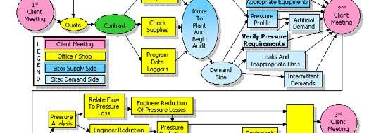
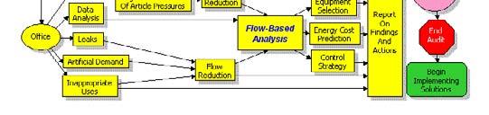
152 17 9
153 9. Data Collection & Analysis 1 9. Data Collection & Analysis Data collection training will consists of several elements: Defining the objectives & information goals Connecting to the system Sensors, transmitters and transducers Data acquisition hardware and software Measurement techniques Analysis Recommendations 2 1
154 9. Data Collection & Analysis Informational goals: Demand profile Pressure profile High volume intermittent demand events Perceived high pressure demands Power consumption Production levels 3 9. Data Collection & Analysis Collect demand data to establish the dynamics of the system. Identify events and their impact on the system. Identify cycle times and duration of these events. Identify periods of system draw-down. 4 2


 Supply")


 5.")


155 9. Data Collection & Analysis 8.5 bar 7.5 bar bar System Pressure Profile (typical) Supply Operating range of compressors Pressure drop from: aftercooler, separator, dryer, filter Demand 6.5 bar Distribution system pressure drop (unregulated end uses) 5.5 bar FRL,valve, hose, and disconnect pressure drop (regulated end uses) 5 9. Data Collection & Analysis Developing a Compressed Air System Profile Data Logging, g Flow, Power and Pressure 6 3
Fundamentals of Compressed Air Systems. Pre-Workshop Assignment
 Page 1 In order to ensure that the Compressed Air Challenge Fundamentals of Compressed Air Systems Training is most useful to you, it will be important for you to bring information about your plant s compressed
Advanced Management of Compressed Air Systems Pre-Workshop Assignment
 Advanced Management of Compressed Air Systems Page 1 In order to ensure that the Compressed Air Challenge Level II Training is most useful to you, it will be important for you to bring information about
Offshore Equipment. Yutaek Seo
 Offshore Equipment Yutaek Seo Flash Gas Compressor (East spar) Dehydration NGL recovery Slug catcher Separator Stabilization Booster compressor Gas export compression (Donghae-1 Platform) May 7 th Gas
FACT SHEET 1. Compressed Air System Selection and Efficient Production. How to save energy, reduce costs and help the environment
 FACT SHEET 1 Compressed Air System Selection and Efficient Production How to save energy, reduce costs and help the environment COMPRESSED AIR USES Compressed air is clean, readily available, and simple
Compressed Air - Food/Bev. Presented By: Adam Zimmerman
 Compressed Air - Food/Bev Presented By: Adam Zimmerman Meeting Summary Metro Air Treatment Compressor Types & Selection Measurment Questions Metropolitan Air Compressor Co., Inc. Serving the Michigan Market
V-Major, V-Compact. Reciprocating Compressors. Intelligent Air Technology
 V-Major, V-Compact Reciprocating Compressors Intelligent Air Technology & Significant Energy Savings with Lower Running Costs Efficient. LOW POWER CONSUMPTION 75% of the running cost of an air compressor
/ /
 GN 4- kw/5.5-0 hp Dual Output Compressors (Air/Nitrogen) Driving Nitrogen Forward GN: the dual output solution From cargo blanketing in LNG vessels to the inflation of Formula tires, nitrogen is used in
Unit 24: Applications of Pneumatics and Hydraulics
 Unit 24: Applications of Pneumatics and Hydraulics Unit code: J/601/1496 QCF level: 4 Credit value: 15 OUTCOME 2 TUTORIAL 11 AIR COMPRESSORS AND DISTRIBUTION SYSTEM The material needed for outcome 2 is
GLOSSARY OF TERMS. Adiabatic Compression Compression process when all heat of compression is retained in the gas being compressed.
 GLOSSARY OF TERMS Absolute pressure Total pressure measured from absolute zero i.e. a perfect vacuum. As a practical matter, gauge pressure plus atmospheric pressure. Absolute temperature Temperature measured
COMPRESSED AIR SYSTEMS AND ENERGY SAVINGS
 COMPRESSED AIR SYSTEMS AND ENERGY SAVINGS Denis Cooke, Denis Cooke & Associates Pty Limited www.decoa.com.au Phone (02) 871 6641 March 1994 DISCLAIMER The author makes no warranties whatsoever in connection
CHAPTER 3 : AIR COMPRESSOR
 CHAPTER 3 : AIR COMPRESSOR Robotic & Automation Department FACULTY OF MANUFACTURING ENGINEERING, UTeM Learning Objectives Identify types of compressors available Calculate air capacity rating of compressor
4-7 kw/ hp. Dual Output Compressors (Air/Nitrogen) Driving Nitrogen Forward
 Driving Nitrogen Forward") GN 4-7 kw/5.5-10 hp Dual Output Compressors (Air/Nitrogen) Driving Nitrogen Forward Total capability, total responsibility Right at the heart of your business, Atlas Copco delivers quality compressed air
GN 4-7 kw/5.5-10 hp Dual Output Compressors (Air/Nitrogen) Driving Nitrogen Forward Total capability, total responsibility Right at the heart of your business, Atlas Copco delivers quality compressed air
THE IMPACT ON ENERGY CONSUMPTION CAUSED BY PRESSURE DROP IN A COMPRESSED AIR SYSTEM
 THE IMPACT ON ENERGY CONSUMPTION CAUSED BY PRESSURE DROP IN A COMPRESSED AIR SYSTEM What is pressure drop in a compressed air utility? Pressure drop is a term used to characterize the reduction in air
Compressors. Basic Classification and design overview
 Compressors Basic Classification and design overview What are compressors? Compressors are mechanical devices that compresses gases. It is widely used in industries and has various applications How they
Selection of gas compressors: part 2
 36 Compressors Selection of gas compressors: part 2 In this multipart series, Eduardo Larralde and Rafael Ocampo aim to provide a comprehensive survey of the current state of the art concerning gas Following
Reliability: Piping Distribution & Storage Matter. Instructor: Kurt Thielemann Principal
 Reliability: Piping Distribution & Storage Matter Instructor: Kurt Thielemann Principal What is the Supply Side? Supply Side Demand Side Supply-side System - Best Practices Comp #1 100 HP Wet Receiver
Liquid ring vacuum pumps in compact design
 Liquid ring vacuum pumps in compact design LEM 25, LEM 5 Pressure range: Suction volume flow: 33 to 113 mbar 4 to 6 m³/h CONSTRUCTION SIHI liquid ring vacuum pumps are displacement pumps of uncomplicated
ME1251 THERMAL ENGINEERING UNIT IV AIR COMPRESSORS
 ME1251 THERMAL ENGINEERING UNIT IV AIR COMPRESSORS UNIT-IV 4. 1 CONTENTS TECHNICAL TERMS 4.1 Classification of compressors 4.2 Positive Displacement compressors 4.2.1 Double acting compressor 4.2.2 Diaphragm
 www.ompressedairsystems.com ultra-high purity nitrogen generators nitrogen purity: 95% to 99.999% www.ompressedairsystems.com ultra-high purity nitrogen generators nitrogen purity: 95% to 99.999% Leading
SRL SEries. Oil Free Scroll Air Compressors hp kw
 SRL SEries Oil Free Scroll Air Compressors 2 44 hp 1.5 33 kw Sullair and Hitachi When Sullair became A Hitachi Group Company in July, 2017 two compressor titans joined forces bringing customers more solutions
Understanding Lobe Blowers Roots Blowers. Article written by Technical Team of EVEREST GROUP
 Understanding Lobe Blowers Roots Blowers Article written by Technical Team of EVEREST GROUP ompressors and Fans are essentially pumps for gases. Although they differ in construction from liquid handling
Applied Fluid Mechanics
 Applied Fluid Mechanics 1. The Nature of Fluid and the Study of Fluid Mechanics 2. Viscosity of Fluid 3. Pressure Measurement 4. Forces Due to Static Fluid 5. Buoyancy and Stability 6. Flow of Fluid and
Earlier Lecture. In the earlier lecture, we have seen Kapitza & Heylandt systems which are the modifications of the Claude System.
 17 1 Earlier Lecture In the earlier lecture, we have seen Kapitza & Heylandt systems which are the modifications of the Claude System. Collins system is an extension of the Claude system to reach lower
Oil-injected rotary screw compressors GA (VSD + )
") Oil-injected rotary screw compressors GA 90 + 160 (VSD + ) Highest reliability, lowest operating costs The shortest route to maximize your profitability is to minimize your operational costs. With up to
Oil-injected rotary screw compressors GA 90 + 160 (VSD + ) Highest reliability, lowest operating costs The shortest route to maximize your profitability is to minimize your operational costs. With up to
Liquid ring vacuum pumps in compact design
 Liquid ring vacuum pumps in compact design, Pressure range: Suction volume flow: 33 to 113 mbar 3 to 58 m³/h CONSTRUCTION TYPE SIHI liquid ring vacuum pumps are displacement pumps of uncomplicated and
SRL Series. Oil-less Scroll Air Compressors. Pharmaceutical. Research & Development. Food & Beverage. Chemical. Electronic
 Pharmaceutical SRL Series Oil-less Scroll Air Compressors Research & Development Food & Beverage Chemical Electronic Hitachi Industrial Equipment Product Brochure Hitachi SRL Series scroll compressors
Membrane modules for nitrogen and oxygen generator systems. Technology Overview ENGINEERING YOUR SUCCESS.
 Membrane modules for nitrogen and oxygen generator systems Technology Overview ENGINEERING YOUR SUCCESS. Parker modules the heart of OEM tailor-made nitrogen generators OEM (Original Equipment Manufacturer)
List of Contents vma. Compressed Air Conditioning 2. System description 2. Individual Units Pre-Filters 3. Combinations 6
 Úprava stlačeného vzduchu EWO VMA List of Contents System description Individual Units Pre-Filters 3 Micro-Filters 4 Activated-Charcoal-Filters 5 Combinations 6 Accessories and Main spare parts 6 Service
Exercise 4-2. Centrifugal Pumps EXERCISE OBJECTIVE DISCUSSION OUTLINE DISCUSSION. Pumps
 Exercise 4-2 Centrifugal Pumps EXERCISE OBJECTIVE Familiarize yourself with the basics of liquid pumps, specifically with the basics of centrifugal pumps. DISCUSSION OUTLINE The Discussion of this exercise
MECHANICAL EQUIPMENTS: COMPRESSORS, PUMPS, SEALS, SPEED DRIVES, CONTROL VALVES & ACTUATORS & SAFETY RELIEF VALVES
 Training Title MECHANICAL EQUIPMENTS: COMPRESSORS, PUMPS, SEALS, SPEED DRIVES, CONTROL VALVES & ACTUATORS & SAFETY RELIEF VALVES Training Duration 5 days Training Venue and Dates REF Mechanical Equipments:
Oxygen Generating Systems Ozone Medical Welding Glassblowing Aquaculture Pulp & Paper Wastewater
 Oxygen Generating Systems General Information Extract oxygen directly from the atmosphere and deliver it to any medical or industrial application with an OGSI oxygen generator. Our standard line of Pressure
Niltox Breathing Air Purifier Range
 Breathing Air Requirements The main standards affecting breathing air are BSEN529, EN12021 and COSHH. The requirements for a breathing air system are shown in the table opposite and the requirements for
Guideline No.M-05(201510) M-05 AIR COMPRESSOR. Issued date: 20 October China Classification Society
 M-05 AIR COMPRESSOR. Issued date: 20 October China Classification Society") Guideline No.M-05(201510) M-05 AIR COMPRESSOR Issued date: 20 October 2015 China Classification Society Foreword This Guideline constitutes the CCS rules, and establishes the applicable technical requirements
Guideline No.M-05(201510) M-05 AIR COMPRESSOR Issued date: 20 October 2015 China Classification Society Foreword This Guideline constitutes the CCS rules, and establishes the applicable technical requirements
ON-SITE INDUSTRIAL GASES. Nitrogen & Oxygen Generators
 ON-SITE INDUSTRIAL GASES Nitrogen & Oxygen Generators A SECURE SUPPLY OF NITROGEN AND OXYGEN Whether your company is specialized in chemical manufacturing, electronics, laser cutting or food and beverage,
Screw Compressors 11-22kW
 INDUSTRIALS GROUP Screw Compressors 11-22kW KSA Plus Fixed Speed, KSV Variable Speed Smart and affordable CHAMPION COMPRESSED AIR TECHNOLOGIES KSA Plus Screw Compressors Up to 45 C ambient temperature
Getting the Most for Your Money
 Air Compressor Guide Getting the Most for Your Money How to Select and Protect Your Air Compressor Investment Evaluating a Compressed Air System Types of Air Compressors Selecting an Air Compressor Maintenance
Liquid ring compressors
 Liquid ring compressors KPH 95652 Compression pressures: 6 to 12 bar(g) Suction volume flow: 2960 to 3600 m³/h 78 to 174 psig 1742 to 2119 cfm DESIGN TYPE SIHI liquid ring compressors are displacement
Revision 2013 Vacuum Technology 1-3 day Good Vacuum Practice 1 Day Course Outline
 Revision 2013 Vacuum Technology 1-3 day Good Vacuum Practice 1 Day Course Outline This training course outline is intended to cover the following: Introduction to vacuum Measurement Lubricated rotary pumps
Design Enhancements on Dry Gas Seals for Screw Compressor Applications
 VDI-Berichte Nr. 1932, 2006 B 8 331 Design Enhancements on Dry Gas Seals for Screw Compressor Applications Dipl.-Ing C. Kirchner, Flowserve Dortmund GmbH & Co KG, Dortmund Introduction The development
CHAPTER 3 AUTOMOTIVE AIR COMPRESSOR
 30 CHAPTER 3 AUTOMOTIVE AIR COMPRESSOR 3.1 INTRODUCTION A machine providing air at a high pressure is called as an air compressor. Air compressors have been used in industry for well over 100 years because
Simplicity in VRU by using a Beam Gas Compressor
 Simplicity in VRU by using a Beam Gas Compressor By Charlie D. McCoy and Mark Lancaster Abstract: Vapor Recovery Units are often expensive, complicated to operate and unable to deal with High H2S and liquids.
Best Practices Pneumatics Machine & Design. Written by Richard F. Bullers, CFPPS as published in Fluid Power Journal, July/August 2016
 Pneumatics Machine & Design Written by Richard F. Bullers, CFPPS as published in Fluid Power Journal, July/August 2016 Contents at Atmospheric Air The air at a compressor s intake contains about 78% nitrogen,
Design. Pompetravaini-NSB API SB Liquid Ring Compressor for Gas Processing. Working Principle
 SB Pompetravaini-NSB API SB Liquid Ring Compressor for Gas Processing A family of API liquid ring compressors has been developed and has been in the market for nearly a decade, they are specifically made
Technical Information
 Technical Information Installation, Operation, Installation, Operation and Maintenance and Maintenance Manual Manual Balston Model 75700-K728 Nitrogen Generator Figure 1-75700-K728 Overall Dimensions These
Vacuum Systems and Cryogenics for Integrated Circuit Fabrication Technology 01
 INAOE. Tonantzintla, Mexico. 2010-06-23. June 23 rd, 2010 Vacuum Systems and Cryogenics for Integrated Circuit Fabrication Technology 01 Joel Molina INAOE Microelectronics Group jmolina@inaoep.mx 1 Vacuum
The Discussion of this exercise covers the following points: Pumps Basic operation of a liquid pump Types of liquid pumps The centrifugal pump.
 Exercise 2-3 Centrifugal Pumps EXERCISE OBJECTIVE In this exercise, you will become familiar with the operation of a centrifugal pump and read its performance chart. You will also observe the effect that
Breathable Compressed Air
 aerospace climate control electromechanical filtration fluid & gas handling hydraulics pneumatics process control sealing & shielding Breathable Compressed Air Typical Hazardous Substances Biological agents
POP Safety Valve. POP Safety Valve INTRODUCTION DEFINITIONS
 POP Safety Valve POP Safety Valve INTRODUCTION The effects of exceeding safe pressure levels in an unprotected pressure vessel or system, can have catastrophic effects on both plant and personnel. Safety
Liquid ring vacuum pumps single-stage
 Liquid ring vacuum pumps single-stage LPH 40106, LPH 40411, LPH 40516 Pressure range: Suction volume flow: 150 to 1013 mbar 50 to 270 m³/h CONSTRUCTION TYPE Sterling SIHI liquid ring vacuum pumps are displacement
SULLAIR SX Filtration Series ,000 scfm
 SULLAIR SX Filtration Series 25 21,000 scfm The Importance of Reliable Filtration Contaminants are introduced at various stages of the air compression cycle. Removing these contaminants is vital to help
CompAir provide high quality and reliable Nitrogen solutions
 Nitrogen Compressor Guide CompAir provide high quality and reliable Nitrogen solutions Technical Data Model Typical Inlet Pressure Max Pressure Typical FAD Drive Bar PSI Bar PSI m³/hr CFM kw HP 5209 B
hydro-pac, inc. Low-Pressure Gas Compressors 1500 to 6000 PSI
 hydro-pac, inc. LX-SERIES Low-Pressure Gas Compressors 1500 to 6000 PSI hydro-pac, inc. LX-SERIES Features Hydro-Pac LX-SERIES Gas Compressors feature: Oil-free non lubricated gas pistons and cylinders
Installation, Operation, and Maintenance Manual Parker Balston Model N2-04 Nitrogen Generator
 Installation, Operation, and Maintenance Manual Parker Balston Figure 1 - N2-04 Nitrogen Generator These instructions must be thoroughly read and understood before installing and operating this product.
Potter Nitrogen Generators
 Potter Nitrogen Generators What is nitrogen? Nitrogen the inert gas Earth s atmosphere the air we breathe is composed of nitrogen, oxygen, and water vapor. While this atmosphere is great for life, it is
The Compact, Portable, Efficient and Economical Solution to boost Shop Compressed Air Pressure by 2 or 3 times
 Tseries Series AB AB Air Air Boosters Boosters The Compact, Portable, Efficient and Economical Solution to boost Shop Compressed Air Pressure by 2 or 3 times.01/1 MANIFOLD MOUNTED VALVES FOR EASY SERVICING
TECHNICAL BULLETIN DESIGNING A FUNCTIONAL COMPRESSED AIR SYSTEM
 TECHNICAL BULLETIN DESIGNING A FUNCTIONAL COMPRESSED AIR SYSTEM The purpose of a compressed air system is to provide an efficient means of transmitting an adequate volume and quality of air to pneumatic
Vortex Tube Short Course February 2017
 Vortex Tube Short Course February 2017 10125 Carver Rd. Cincinnati, OH 45242 1.800.441.7475 sales@vortec.com Vortex Tube Short Course The vortex tube has been around for decades, yet occasionally it is
Theoretical and Experimental Study on Energy Efficiency of Twin Screw Blowers Compared to Rotary Lobe Blowers
 Theoretical and Experimental Study on Energy Efficiency of Twin Screw Blowers Compared to Rotary Lobe Blowers Mr. Gert an Leuven Team leader Product Development Atlas Copco Airpower n.v., Wilrijk, Belgium
COMPRESSED AIR SYSTEMS A-Z COMP AIR COMPRESSOR TRAINIBG
 COMPRESSED AIR SYSTEMS 1 SCOPE OF WORK Various types of compressors and their characteristics Measurement of power consumption, free air delivery, operating pressure, Isothermal power required, and volumetric
Introduction to Pumps
 Introduction to Pumps 1 Introduction to Pumps 1.0 INTRODUCTION There are many different types of pump now available for use in pumped fluid systems. A knowledge of these pump types and their performance
Liquid ring vacuum pumps in compact design
 Liquid ring vacuum pumps in compact design LEM 26, LEM 51 Pressure range: Suction volume flow: 33 to 113 mbar 3 to 58 m³/h CONSTRUCTION TYPE SIHI liquid ring vacuum pumps are displacement pumps of uncomplicated
Sullair Air Systems. *Assessment of the market for compressed air efficiency services. Technical report, U.S. Department of Energy, June 2001
 Sullair Air Systems The three most expensive components in operating a compressed air system are: inadequate, inefficient controls that waste energy; lost production due to an improperly maintained system;
Quick Reference Technical Data
 Bulletin 127C 2 Quick Reference Technical Data For over 100 years, The Spencer Turbine Company has specialized in innovative solutions to air and gas handling problems. Spencer's product line includes
Hot Water Stationary Unit
 S 312 E-VA Hot Water Stationary Unit Technical Data S 312 E-VA (18 kw) Flow rate max. 620 l/h Unloading pressure 190 bar Working pressure max. 30-170 bar Water temperature max. 45 C Water inlet 3/4 Power
Crab and Lobster Live Holding System Part II (Water Pumps, Air Pumps and Pipework)
") Crab and Lobster Live Holding System Part II (Water Pumps, Air Pumps and Pipework) 1990/2/SF/AM The increased demand for crabs and lobsters, and the requirement to export live shellfish has led to the
Crab and Lobster Live Holding System Part II (Water Pumps, Air Pumps and Pipework) 1990/2/SF/AM The increased demand for crabs and lobsters, and the requirement to export live shellfish has led to the
COMPRESSORS AND COMPRESSED AIR SYSTEMS
 COMPRESSORS AND COMPRESSED AIR SYSTEMS 1. INTRODUCTION... 1 2. TYPES OF COMPRESSORS... 3 3. ASSESSMENT OF COM PRESSORS AND COMPRESSED AIR SYSTEMS... 8 4. ENERGY EFFICIENCY OPPORTUNITIES... 13 5. OPTION
RDK-408D2 Cold Head. Technical Manual. SHI-APD Cryogenics Inc Vultee Street Allentown, PA U.S.A. Revision A: September 2005
 RDK-408D2 Cold Head Technical Manual SHI-APD Cryogenics Inc. 1833 Vultee Street Allentown, PA 18103-4783 U.S.A. Revision A: September 2005 (Reference SHI Manual: December 18, 2003 266404A CD32ZZ-160A)
Atlas Copco. On-site Industrial Gases Nitrogen & Oxygen Generators
 Atlas Copco On-site Industrial Gases Nitrogen & Oxygen Generators A secure supply of nitrogen and oxygen Whether your company is specialized in chemical manufacturing, electronics, laser cutting or food
Breathing Air Purifiers. Comply with European Pharmacopoeia and International Breathing Air Standards
 Breathing Air Purifiers Comply with European Pharmacopoeia and International Breathing Air Standards 1 Breathing Air Purifiers domnick hunter Breathing Air Purifiers provide air 1,000,000 times cleaner
TECHNICAL BULLETIN COMPRESSED AIR & GAS TERMINOLOGY
 TECHNICAL BULLETIN COMPRESSED AIR & GAS TERMINOLOGY ABSOLUTE MICRON RATING A filter rating that requires that ALL (not just 98%) particles larger than the indicated micron size have been removed from the
NEW POLYTECHNIC, KOLHAPUR
 Content: 3.1 Classification of air compressor - Construction and working of single stage and two stage reciprocating air compressors with P-V. diagram. Necessity of multistaging and inter cooling. Construction
Pressure and/or Temperature Pilot Operated Steam Regulators Series 2000
 Hoffman Specialty Regulators Regulators Pressure and/or Temperature Operated Regulators Series 2000 The Hoffman Specialty Series 2000 consists of main valves, pilot valves, wells and hardware kits. They
TECHNICAL INFORMATION
 TECHNICAL INFORMATION Installation, Operation, and Maintenance Balston Model 75-77 Nitrogen Generator Figure 1-75-77 Overall Dimensions These instructions must be thoroughly read and understood before
Mobile High Pressure Compressor Unit for Compressing Air and Breathing Air. PE 250-TE with compressor control (optional equipment)
") Mobile High Pressure Compressor Unit for Compressing Air and Breathing Air Types: PE 200-TE PE 250-TE PE 300-TE Production status: F02 PE 250-TE with compressor control (optional equipment) General Medium
Mobile High Pressure Compressor Unit for Compressing Air and Breathing Air Types: PE 200-TE PE 250-TE PE 300-TE Production status: F02 PE 250-TE with compressor control (optional equipment) General Medium
WORKHOLDING APPLICATION BOOKLET
 WORKHOLDING APPLICATION BOOKLET Applications and advantages of using minibooster hydraulic pressure intensifiers MINIMUM SIZE MAXIMUM POWER B-GB Workholding 2018.04 1 of 20 2 of 20 B-GB Workholding 2018.04
ENGINEERING FLUID MECHANICS
 DEPARTMENT of MECHANICAL ENGINEERING FLUID MECHANICS Subject code: 10ME46B Faculty name: Naveen H E QUESTION BANK UNIT-1: FLUID PROPERTIES 1. Define the following: i) density, ii) weight density, iii)
Pneumatic Conveying Principles BSH&E SEMINAR
 Pneumatic Conveying Principles Definition What is Pneumatic Conveying? A method for conveying bulk material using gas (usually air) The material can be blown (pressure systems) or sucked (vacuum systems)
Compressor Seal Replacement and Upgrades SERVICES
 Compressor Seal Replacement and Upgrades SERVICES Compressor Seal Upgrades An Elliott Group compressor seal upgrade increases seal reliability and reduces process gas leakage to improve overall efficiency.
SF SERIES CNG COMPRESSOR MODEL HF-4MH. 4 Nm3/Hour Displacement OPERATION MANUAL
 SF SERIES CNG COMPRESSOR MODEL HF-4MH 4 Nm3/Hour Displacement OPERATION MANUAL 1 Content 1. General Description...3 2. Main technical parameters...3 3. Structural principle...4 3.1Main structure...4 3.2Compressor
Mounting and operating instructions EB 2530 EN. Self-operated Pressure Regulator. Pressure Reducing Valve Type M 44-2
 Self-operated Pressure Regulator Pressure Reducing Valve Type M 44-2 Type M 44-2, connection G 1 4, K VS = 0.15 Type M 44-2, connection G 1, K VS = 6 Fig. 1 Type M 44-2 Pressure Reducing Valve Mounting
Tradition & Technology
 Gaterotor Support Gaterotor Single Screw Compressors Design & Operation Bearing Bearings Main Screw Parallex Slide System The VSM Single Screw Compressor has one main rotor and two gaterotors. All bearings
OPERATION MANUAL NTF-60 Plus
 OPERATION MANUAL NTF-60 Plus Nitrogen Tire Filling Valve Stem Caps (Qty=200) Order P/N 436075 RTI Technologies, Inc 10 Innovation Drive York, PA 17402 800-468-2321 www.rtitech.com 035-81264-00 (Rev A)
Pressure on Demand. Air Pressure Amplifiers
 Pressure on Demand Air Pressure Amplifiers Introduction Haskel air pressure amplifiers offer the most comprehensive range in the industry combining simple principles of operation with rugged construction
Liquid ring compressors
 Liquid ring compressors KPH 85220, KPH 85227 Compression pressures: Suction volume flow: 2 to 7 bar 940 to 1450 m³/h CONSTRUCTION TYPE Sterling SIHI liquid ring compressors are displacement compressors
NGN Series nitrogen generator
 NGN Series 8-64 nitrogen generator Applications how it works RK series 5-40 F Blanketing of Chemicals and Pharmaceuticals Gas Assisted Injection Moulding (GAIM) Laser Cutting Food Heat Treament of Ferrous
Nirvana Variable-Speed Drive, Contact-Cooled Rotary Screw Air Compressors
 Variable-Speed Drive, Contact-Cooled Rotary Screw Air Compressors Exceptional Reliability Introducing - A True Variable-Speed Drive Compressor Now Available in Single- and Two-Stage. By matching a standard
Another convenient term is gauge pressure, which is a pressure measured above barometric pressure.
 VACUUM Theory and Applications Vacuum may be defined as the complete emptiness of a given volume. It is impossible to obtain a perfect vacuum, but it is possible to obtain a level of vacuum, defined as
Atlas Copco Tools & Assembly Systems. Air Line Accessories Optimizers- FRL
 Atlas Copco Tools & Assembly Systems Air Line Accessories Optimizers- FRL MIDI Optimizer FRL Why use an Atlas Copco FRL? Atlas Copco filters, regulators, and lubricators are designed to help you get maximum
Let s examine the evolution and application of some of the more popular types. Cascading Pressure Type
 Your facility personnel typically know when not enough air compressors are operating. The demand side system air pressure drops below what is required for production triggering phone calls and complaints.
OPERATION MANUAL NTF-15
 OPERATION MANUAL NTF-15 Nitrogen Tire Filling Valve Stem Caps (Qty=200) Order P/N 436075 RTI Technologies, Inc 10 Innovation Drive York, PA 17402 800-468-2321 www.rtitech.com 035-81235-00 (Rev B) TABLE
CO 2 radial piston compressor (transcritical)
") CO 2 radial piston compressor (transcritical) At a glance Operating limits and performance data Technical data Dimensions and connections Scope of supply 124 126 129 130 131 Radial piston compressor (transcritical)
CO 2 radial piston compressor (transcritical) At a glance Operating limits and performance data Technical data Dimensions and connections Scope of supply 124 126 129 130 131 Radial piston compressor (transcritical)
Liquid ring compressor
 Liquid ring compressor KLH 47005, KLH 47105 Compression pressures: Suction volume flow: 2 to 11 bar 56 to 65 m³/h CONSTRUCTION TYPE Sterling SIHI liquid ring compressors are displacement compressors of
Measurement Technology
 In the field of compressed air, measuring pressure provides the data basis for rating the correct pressure head of pressure differences in the distribution system as well as for controlling and regulating
SIHI LPH-X - Liquid Ring Compressors
 - Liquid Ring Compressors LPH 50523 LPH 60527 Pressure range: Suction volume range: 0.2 to 1.5 bar 260 to 780 m³/h CONSTRUCTION Sterling SIHI liquid ring compressors are displacement compressors with a
Pressure and Flow Control Valves DBGM, German and European Patents
 Pressure and Flow Control Valves DBGM, German and European Patents Absolutely Reliable Pressure and Flow Control In water mains of sizes DN 50 to DN 150, ERHARD Control Valves in straight or angle pattern
Flow meter. bellow vaporizer. APL valve. Scavenging system
 Introductory Lecture Series: The Anesthesia Machine PORNSIRI WANNADILOK Objectives Anesthesia Machine Ventilators Scavenging Systems System Checkout 1 Flow meter ventilator bellow vaporizer Corrugated
OPERATING INSTRUCTIONS Pressure Control System PCS-20 through PCS-100
 107 W. Main Street Worthington, PA 16262 Phone: 724.297.3416 Fax: 724.297.5189 http://www.airtak.com OPERATING INSTRUCTIONS Pressure Control System PCS-20 through PCS-100 12-2007 TABLE OF CONTENTS PAGE
OWNER S TECHNICAL MANUAL
 EL SERIES OWNER S TECHNICAL MANUAL DP7002 1 Air Operated Diaphragm Pump Description The DP7002 1 air operated diaphragm pump is the ideal device for the pumping, transfer and dispensing of chemical liquids,
Air Amplifiers & SYSTEMS
 Air Amplifiers & SYSTEMS We Accept VISA, MasterCard and American Express Air Amplifiers Point-of-Use Air Solutions Maximator air amplifiers are designed to boost plant air pressure or increase the supply
Understanding Centrifugal Compressor Capacity Controls:
 Understanding Centrifugal Compressor Capacity Controls: Richard Stasyshan, CAGI Technical Consultant and the Centrifugal Compressor Section of the Compressed Air & Gas Institiute (CAGI). CAGI and our centrifugal