M-5071/1111. Electronic Pressure Switch PSW14 series
|
|
|
- Audrey Richards
- 5 years ago
- Views:
Transcription


1 M-507/ Electronic Pressure Switch PSW4 series

2
3 S TABLE OF CONTENTS Electronic Pressure Switch PSW4 Series Intended Applications... Safety Instructions... 3 Standards... 4 Warranty/Guaranty... 5 Installation/Commissioning... 6 Maintenance/Cleaning Technical Data Operation Programming... 5 i
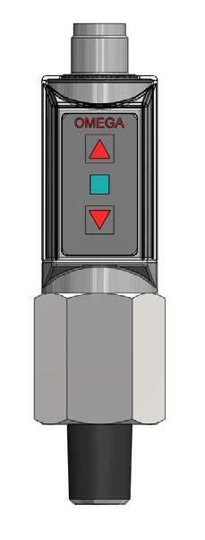
4 Intended Applications The pressure switch serves for monitoring a pressure system and has one or two switching outputs. DANGER The switch may only be used in the specified fields of application. The stated pressures and electrical load values must not be exceeded. Observe also the applicable national safety instructions for assembly, commissioning and operation of the switch. The switch is not designed to be used as the only safety relevant element in pressurized systems according to DGR 97/3/EC. Safety Instructions The safety instructions are intended to protect the user from dangerous situations and/or material damage. In the operating instructions the seriousness of the potential risk is designated by the following signal words: Function Membrane keys LED Reset RS pressing the membrane key T. Press the membrane keys T and T for 4 s. The LED flashes for s green and red at Error The LED flashes alternatingly red and green. The LED shines green, when the fault has been eliminated. SP > RS: increasing pressure evaluation SP < RS: decreasing pressure evaluation 9. Version with two switch points *** Re-actuation hysteresis 5 %, increasing pressure evaluation DANGER Refers to imminent danger to men. Nonobservance may result in fatal injuries. WARNING Refers to a recognizable danger. Nonobservance may result in fatal injuries, and destroy the equipment or plant parts. CAUTION Refers to a danger. Nonobservance may result in light injuries and material damage to the switch and/or to the plant. Refers to important information essential to the user. Disposal The switch must be disposed of correctly in accordance with the local regulations for electric/electronic equipment. The switch must not be disposed of with the household garbage! Function Membrane keys LED Activate teaching Press the membrane keys (T) and (T) for 4 s. SP teaching SP teaching Reset SP Reset SP Press the membrane key T for 4 s. The current value for SP is transferred to the pressure switch. When the operation is aborted, SP is not updated. Press the membrane key T for 4 s. The current value for SP is transferred to the pressure switch. When the operation is aborted, SP is not updated. pressing the membrane key T. Press the membrane keys T and T for 4 s. pressing the membrane key T. Press the membrane keys T and T for 4 s. The LED flashes alternatingly for s red and green. During these s SP and/or SP have to be teached. Subsequently the LED The LED shines red for 4 s. The LED flashes red 3x, after the pressure switch has updated SP. The LED shines green for 4 s. The LED flashes green 3x, after the pressure switch has updated the SP. The LED flashes for s red and green at The LED flashes for s green and red at Error The LED flashes alternatingly red and green. The LED shines green, when the fault has been eliminated. 6
5 8 Operation The switch may only be put into service and operated by authorized persons. Do not use any hard objects for making entries. A self-test is performed on first commissioning. The pressure switch is operated via two membrane keys. These must not be touched by means of hard objects. When power supply is switched on the operational status of the switch is indicated by a green LED. The switching function is not optically indicated. 9 Programming The pressure switch is programmed by means of the membrane keys (T) and (T). 9. Version with one switch point * The switch point SP is set to the measuring range end value. ** The re-actuation point RS is set to the measuring range end value. Function Membrane keys LED Activate teaching Press the membrane keys (T) and (T) for 4 s. SP teaching Press the membrane key T for 4 s. The current value for the SP is transferred to the pressure switch. When the operation is aborted, the SP is not updated. The LED flashes alternatingly for s red and green. Subsequently the LED shines green. The LED shines red for 4 s. The LED flashes red 3x, after the pressure switch has updated the SP. 3 Standards The standards applied during development, manufacture and configuration are listed in the CE conformity and manufacturer's declaration. 4 Warranty/Guaranty Warranty Our scope of delivery and services is governed by the legal warranties and warranty periods. Terms of guaranty We guaranty for function and material of the pressure switch under normal operating and maintenance conditions in accordance with the statutory provisions. Loss of guaranty The agreed guaranty period will expire in case of: incorrect use incorrect installation or incorrect handling or operation contrary to the provisions of these operating instructions No liability is assumed for any damage resulting there from, or any consequential damage. 5 Installation/Commissioning DANGER Only install or uninstall the switch when deenergized (electrically and hydraulically/pneumatically). Pressure connection and electrical connection must be carried out by trained or instructed personnel according to state-of-the-art standards. The switch must only be installed in systems where the maximum pressure P max is not exceeded (see type label). WARNING Be aware of the fact that in case of operation with higher temperatures the casing surface may become very hot! RS teaching Press the membrane key T for 4 s. The current value for the RS is transferred to the pressure switch. Reset SP When the operation is aborted, the RS is not updated. pressing the membrane key T. Press the membrane keys T and T for 4 s. The LED shines green for 4 s. The LED flashes green 3x, after the pressure switch has updated the RS. The LED flashes for s red and green at CAUTION Mount the pressure switch from the bottom to the tting with a wrench SW 4 and tighten to a torque of 45 Nm torque. Do not put the switch into operation when the switch itself or the connection cable is damaged. Avoid impact and severe vibration during transport. Even if the switch housing remains undamaged inside parts may be damaged and cause malfunctions. 5

 Version with switching outputs ( switch points SP/SP) +Ub (5... 3 V DC) - SP (0. A max.")
6 Electrical connection is to be carried out dependent on the type of switch (see type label) according to the chart below. Wrong assignment of the connections may cause malfunctions or incorrect switch outputs. 7 Technical Data PSW4 Plug M x 4-pin Pin brown Pin white Pin 3 blue Pin 4 black Version with switching output ( switch point SP) +Ub ( V DC) Version with switching outputs ( switch points SP/SP) +Ub ( V DC) - SP (0. A max.) NO 0 V 0 V SP (0. A max.) NO SP (0. A max.) NO Measuring element Measuring ranges Transistor switching outputs PNP Piezoresistive silicon measuring cell with internal stainless steel diaphragm or ceramic measuring cell bar to bar psi to psi relative pressure or x NO contacts Operating temperature range C / F Media temperature range C / F Process connection (fitting "A" without adapter) Protection system/class G/4 IP65/III Electrical connection Plug 4-pin, M x +Ub +Ub Auxiliary power V DC For further technical data and options please refer to the data sheets SP 0 V 3 SP SP 0 V Operating and display elements/dimensions Mx Dimensions (example) mm (in) (0.9) WARNING Check the operation of the switch regularly. If the switch does not work properly, stop operation immediately! 6 Maintenance/Cleaning The switch requires no maintenance. CAUTION The membrane keys may be damaged by the use of unsuitable cleaning agents. Do not use any cleaning agents containing solvents or abrasive additives. approx (.65) 4 (0.94) SW 4 Item : LED Operational status green indicator red Item : Membrane keys T T Programming keys "Up and "Down 7 (0.67) /4" NPT 3 4
Contents. Operating instructions. Pressure switch, heavy-duty version Model PSM-520
 Operating instructions Contents EN Pressure switch, heavy-duty version Model PSM-520 1. General information 2. Design and function 3. Safety 4. Transport, packaging and storage 5. Commissioning, operation
Actuating elements for ComEx
 Description A large number of variants and versions of actuating elements are available for the ComEx control and indicator units. All actuating elements are made of high-quality thermoplastic and conform
Operating instructions Safety Rope Emergency Stop Switches ZB0052 / ZB0053 ZB0072 / ZB0073
 Operating instructions Safety Rope Emergency Stop Switches UK ZB0052 / ZB0053 ZB0072 / ZB0073 7390878 / 02 03 / 2011 Contents 1 Safety instructions...3 2 Installation / set-up...4 2.1 Applications...4
Declaration of Conformity as per Directive 97/23/EC
 Declaration of Conformity as per Directive 97/23/EC The manufacturer declares that:, 47906 Kempen, Germany Multi-way diverting valves Series 29a and Series 29b, with packing with lever 1. The valves are
FPD20 Series. Gear wheel flow sensor
 . FPD20 Series Gear wheel flow sensor Series FPD20-2 - M-5455/0315 Series FPD20 Table of contents page 0 About this operating manual... 4 1 Device description... 5 1.1 Intended use... 5 1.2 Exclusion of
Rocker valve. Type Operating Instructions. Bedienungsanleitung Manuel d utilisation
 Type 0127 Rocker valve 2/2 or 3/2-way solenoid valve 2/2 oder 3/2-Wege Magnetventil Vanne magnétique 2/2 ou 3/2 Operating Instructions Bedienungsanleitung Manuel d utilisation Contents 1 Operating Instructions...2
Mounting and Operating Instructions EB EN. Type Supply Pressure Regulator. with increased air capacity
 Type 4708-45 Supply Pressure Regulator with increased air capacity Translation of original instructions Mounting and Operating Instructions EB 8546-1 EN Edition March 2016 Note on these mounting and operating
SITRANS. Pressure transmitter SITRANS P, Z series for gauge and absolute pressure. Introduction. Safety instructions 2.
 Introduction 1 Safety instructions 2 SITRANS Pressure transmitter SITRANS P, Z series for gauge and absolute pressure 7MF1564 Description 3 Assembly and connection 4 Technical data 5 Dimensional drawings
Declaration of Conformity as per Directive 97/23/EC
 Declaration of Conformity as per Directive 97/23/EC The manufacturer declares that:, 47906 Kempen, Germany Continuous, inline sampling valves Series 27f, with packing Operate with either; Star lever, or
Type 3709 Pneumatic Lock-up Valve. Translation of original instructions. Mounting and Operating Instructions EB 8391 EN
 Type 3709 Pneumatic Lock-up Valve Translation of original instructions Mounting and Operating Instructions EB 8391 EN Edition July 2017 Note on these mounting and operating instructions These mounting
Declaration of Conformity as per Directive 97/23/EC and Manufacturer s Declaration as per Directive 98/37/EC
 Declaration of Conformity as per Directive 97/23/EC and Manufacturer s Declaration as per Directive 98/37/EC The manufacturer declares that:, 47906 Kempen, Germany Continuous, PFA-lined, inline sampling
Differential Pressure Regulator Type Type 45-6 (0.1 to 1 bar, DN 15) Mounting and Operating Instructions EB 3226 EN
 Mounting and Operating Instructions EB 3226 EN") Differential Pressure Regulator Type 45-6 Type 45-6 (0.1 to 1 bar, DN 15) Mounting and Operating Instructions EB 3226 EN Edition March 2008 Contents Contents Page 1 Design and principle of operation...................
Differential Pressure Regulator Type 45-6 Type 45-6 (0.1 to 1 bar, DN 15) Mounting and Operating Instructions EB 3226 EN Edition March 2008 Contents Contents Page 1 Design and principle of operation...................
Declaration of Conformity as per Directive 97/23/EC
 Declaration of Conformity as per Directive 97/23/EC The manufacturer declares that:, 47906 Kempen, Germany Discontinous, inline sampling valves Series 27a and Series 27g, with packing with lever (180 )
Inverted Bucket Steam Trap IB 16A-7
 Inverted Bucket Steam Trap IB 16A-7 Original Installation Instructions 819114-02 Contents Preface... 3 Availability... 3 Text layout... 3 Safety... 3 Usage for the intended purpose... 3 Basic safety notes...
Operating instructions Capacitive sensor KIA (M30) / / 2010
 / / 2010") Operating instructions Capacitive sensor KIA (M30) UK 704182 / 03 07 / 2010 Contents 1 Preliminary note 3 2 Safety instructions 3 3 Functions and features 3 3.1 Application examples 4 4 Installation 4
Operating instructions Capacitive sensor KIA (M30) UK 704182 / 03 07 / 2010 Contents 1 Preliminary note 3 2 Safety instructions 3 3 Functions and features 3 3.1 Application examples 4 4 Installation 4
Pneumatic proportional controller Types M Types FM Function tested for use of the float in Ex-zone 0
 Operating Manual LTIA5E Pneumatic proportional controller Types M Types FM Function tested for use of the float in Ex-zone 0 Contents 1. Safety Instructions 2. Conformity to standards 3. Technical data
Technical Data Sheet MF010-O-LC
 Technical Data Sheet MF010-O-LC - 1 - 1. Properties The oxygen measuring system MF010-O-LC determines the oxygen content in gas mixtures up to a temperature of 250 C. It is particularly suitable for the
SP21 / SP22. Instructions for installation and operation. EN - english
 EN - english Instructions for installation and operation Pressure transducer METPOINT PRM SP21 / SP22 10-048 Dear customer, Thank you for deciding in favour of the METPOINT PRM SP21 / SP22 pressure transducer.
Mounting and Operating Instructions EB 8546 EN. Supply Pressure Regulator Type Fig. 1 Supply pressure regulators
 Supply Pressure Regulator Type 4708 Type 4708-5352 on Type 3730 Positioner Type 4708-52 with filter receptacle Type 4708-6252 on Type 3372 ctuator Fig. Supply pressure regulators Mounting and Operating
Mounting instructions. Strain transducer SLB-700A. B 26.SLB700A.10 e
 Mounting instructions Strain transducer SLB-700A B 26.SLB700A.10 e SLB700A 3 Contents Page Safety instructions.............................................. 4 1 Applications..................................................
QPL... Pressure Switches. Siemens Building Technologies HVAC Products
 7 221 Pressure Switches QPL... The pressure switches are used for monitoring gas or air pressures. When the pressure falls below the switching point, the associated electrical circuit will open or switch
Electropneumatic Positioner and Pneumatic Positioner Type 3760 JIS
 Electropneumatic Positioner and Pneumatic Positioner Type 3760 Application Single-acting positioners for direct attachment to pneumatic control valves. An electric standardized signal of 4 to 20 ma or
Type 0404 / /2-way solenoid valve 2/2-Wege-Magnetventil Électrovanne 2/2 voies Operating Instructions Bedienungsanleitung Manuel d utilisation
 Type 0404 / 5404 2/2-way solenoid valve 2/2-Wege-Magnetventil Électrovanne 2/2 voies Operating Instructions Bedienungsanleitung Manuel d utilisation 1 OPERATING INSTRUCTIONS The operating instructions
Type /2-Way Globe Valve 3/2-Wege-Geradsitzventil Vanne à siège droit 3/2 voies Operating Instructions Bedienungsanleitung Manuel d utilisation
 3/2-Way Globe Valve 3/2-Wege-Geradsitzventil Vanne à siège droit 3/2 voies Operating Instructions Bedienungsanleitung Manuel d utilisation We reserve the right to make technical changes without notice.
L3 Pressure and Level transmitter
 SENSORS FOR AND BIOPHARMA. Product Information L3 L3 Pressure and Level transmitter Range of applications Hydrostatic Level measurement in dynamic temperature environments Pressure measurement in pipes
Operating instructions Pressure sensor. PP00xE /00 10/2011
 Operating instructions Pressure sensor PP00xE 704962/00 0/20 Contents Preliminary note3. ymbols used 3 2 afety instructions 3 3 Functions and features 4 3. Application area 4 4 Function 4 4. Communication,
RTD Temperature sensor TH11
 RTD Temperature sensor TH11 Compact Instructions Measuring System General purpose RTD with connection head TH11 for process and laboratory applications. The single element RTD is specifi cally designed
MANUAL. Sesame. Thermoplastic Tank Technologies
 MANUAL Sesame Thermoplastic Tank Technologies INSTALLATION AND USER GUIDE CONTENT 1. GENERAL 3 2. IMPORTANT 3 3. INSTALLATION EXPANSION VESSEL 4 4. USE EXPANSION VESSEL 5 5. AIR CELL REPLACEMENT 5 5.1
Safety. Operating instructions Solenoid valve for gas VG 6 VG 15/10 DANGER. Contents WARNING CAUTION. Changes to edition 09.14
 15 Elster GmbH Edition 7.15 Translation from the German 519 D F NL I E DK S N P GR TR CZ PL RUS H www.docuthek.com Operating instructions Solenoid valve for gas VG VG 15/1 Contents Solenoid valve for gas
Electropneumatic Positioner and Pneumatic Positioner Type 3760 JIS
 Electropneumatic Positioner and Pneumatic Positioner Type 3760 Application Single-acting positioners for direct attachment to pneumatic control valves. Supplied with an electric input signal of 4 to 20
HBLT-A1 LIQUID LEVEL SENSOR
 Instruction manual HBLT-A1 LIQUID LEVEL SENSOR for measuring liquid level in refrigerant vessels Instruction manual HBLT - A1 - Liquid level Transmitter (HBLT-A1-008-UK) 1 / 16 Contents Safety instructions...
Operating Manual VSA100A. tina29e1 ( )
") Operating Manual Incl. EU Declaration of Conformity Vacuum Switch VSA100A tina29e1 (2017-05) 1 Product Identification In all communications with INFICON, please specify the information on the product nameplate.
Operating Manual Incl. EU Declaration of Conformity Vacuum Switch VSA100A tina29e1 (2017-05) 1 Product Identification In all communications with INFICON, please specify the information on the product nameplate.
Operating Manual * * Pressure Transmitter. Table of Content. 1 Safety Guidelines. 1.3 Risks due to Non-Observance of Safety Instructions
 *09005184* BA_EN_ME11 Rev.B 09/15 *09005184* d e v e l o p i n g s o l u t i o n s ME11 Operating Manual Pressure Transmitter Table of Content 1 Safety Guidelines 2 Application Purpose 3 Description of
KTE6000 / KTU6000 Series OEM pressure transmitters for industrial media
 FEATURES 50 mbar to 400 bar, 5 to 6000 psi gage or absolute pressure For many industrial gases and liquids 00, 0545, 05, 6 or 40 ma output Field interchangeable EMC according to EN 66-8 MEDIA COMPATIBILITY
* * Data Sheet and Operating Manual. Digital manometer ME01 ## # 87 # HL S#### Dust explosion protection Zone 22.
 *09005087* DB_BA_EN_ME01_S Rev.A 12/16 *09005087* d e v e l o p i n g s o l u t i o n s Data Sheet and Operating Manual ME01 Digital manometer Table of Contents ME01 ## # 87 # HL S#### Dust explosion protection
INSTRUCTION MANUAL Pressure Relief Device LPT
 INSTRUCTION MANUAL Pressure Relief Device LPT 5COV475800 LPT REV00 CONTENT: 1 SAFETY 1.1 Safety instructions 2 1.2 Specified applications 2 1.3 Safety notes on the equipment operation 2 2 PRESSURE RELIEF
Pressure Reducing Valve DMV 750 set range: bar
 Pressure Reducing Valve DMV 750 set range:.0-6.0 bar Advantage pressure setting possible at any time, also during operation hermetically sealed by valve diaphragm high level of operating safety and long
2 Overview. SITRANS P measuring instruments for pressure. Transmitters for gage and absolute pressure. Z series for gage pressure
 Z series for gage pressure Overview Design The main components of the pressure transmitter are: Brass housing with silicon measuring cell and electronics plate Process connection Electrical connection
Mounting and Operating Instructions EB 8546 EN. Type 4708 Supply Pressure Regulators. Translation of original instructions. Type Type
 Type 4708 Supply Pressure Regulators Translation of original instructions Type 4708-53 Type 4708-64 Type 4708-12 Mounting and Operating Instructions Edition March 2018 Note on these mounting and operating
Type 2000 INOX. Quickstart. English Deutsch Français. 2/2-way angle seat valve 2/2-Wege Schrägsitzventil Vanne à siège incliné 2/2 voies
 Type 2000 INOX 2/2-way angle seat valve 2/2-Wege Schrägsitzventil Vanne à siège incliné 2/2 voies Quickstart English Deutsch Français Contents 1 QUICKSTART... 2 2 CONTACT ADDRESS... 2 3 INTENDED USE...
Type Pressure Regulator. for increased air capacity. Fig. 1: Type Pressure Regulator. Mounting and Operating Instructions EB EN
 Type 4708-45 Pressure Regulator for increased air capacity Fig. 1: Type 4708-45 Pressure Regulator Mounting and Operating Instructions EB 8546-1 EN Edition March 2010 Definition of the signal words used
Instruction Manual Contact Pressure Vacuum Gauge
 MS10 Instruction Manual Contact Pressure Vacuum Gauge Table of Contents 1. Safety Instructions 2. Intended Applications 3. Product Description and Functions 4. Installation 5. Commissioning 6. Maintenance
Mounting and Operating Instructions EB 2558 EN. Self-operated Pressure Regulators. Type Pressure Build-up Regulator
 Self-operated Pressure Regulators Type 2357-31 Pressure Build-up Regulator with safety function and integrated excess pressure valve Type 2357-31 with non-return unit at port C Ports A and B with soldering
Sensor for Air Bubble Detection at Liquid Filled Tubes. SONOCHECK Type ABD06.xx. Operating Manual
 Sensor for Air Bubble Detection at Liquid Filled Tubes SONOCHECK Type ABD06.xx Operating Manual Manufacturer: Model: Type: SONOTEC Ultraschallsensorik Halle GmbH Air Bubble Detector ABD06.xx SONOTEC Ultraschallsensorik
SITRANS P measuring instruments for pressure
 SITRANS P measuring instruments for pressure Z series for gage pressure Siemens AG 008 Overview Design The main components of the pressure transmitter are: Brass housing with silicon measuring cell and
Mounting and Operating Instructions EB 3007 EN. Self-operated Pressure Regulators. Type Type Differential Pressure Regulators (opening)
") Self-operated Pressure Regulators Type 42-20 Type 42-25 Differential Pressure Regulators (opening) Translation of original instructions Type 42-20 Differential Pressure Regulator Type 42-25 Differential
Self-operated Pressure Regulators Type 42-20 Type 42-25 Differential Pressure Regulators (opening) Translation of original instructions Type 42-20 Differential Pressure Regulator Type 42-25 Differential
Operating Instructions
 Operating Instructions Light-metal Ex d enclosures / flameproof enclosure > 8265/0 Empty enclosure > 8265/4 Control panel, integrated in Ex e enclosure > 8265/5 Control panel Table of Contents 1 Table
Type BBS-03, BBS-05, BBS-06, BBS-25
 Type BBS-03, BBS-05, BBS-06, BBS-25 Sterile connection elements Sterile Verbindungselemente Raccords union stériles Operating Instructions Bedienungsanleitung Manuel d utilisation 1. THE OPERATING INSTRUCTIONS
User Instruction Manual
 User Instruction Manual 4500 psi Air Compressor Ver 2, 1.18 Contents Parts Included...3 Assembly Instructions...3-5 Operation Instructions...6-7 Oil Change Intervals...8 Air Filter Replacement...9 Setting
Operating Manual. Diaphragm Seals Models , 107, , 207,
 Operating Manual Diaphragm Seals Models 100-105, 107, 200-205, 207, 300-304 (non-electrical device) in an ####=ATEX finish For explosion risk areas in accordance with Directive 94/9/EC (ATEX) Zone 1 and
Safety Please read and keep in a safe place Operating instructions Linear flow control VFC Linear flow control with actuator IFC
 05 Elster GmbH Edition 0.5 Translation from the German 058 D F NL I E DK S N P GR TR CZ PL RUS H www.docuthek.com Operating instructions Linear flow control VFC Linear flow control with actuator IFC Contents
DK48 - DK800. Quick Start. Variable area flowmeter
 Quick Start Variable area flowmeter General safety notes You can find the newest and/or additional information in the handbook, the datasheet, special manuals, certificates and the download center at www.krohne.com.
Mounting and Operating Instructions EB 3007 EN. Self-operated Pressure Regulators. Differential Pressure Regulators (opening) Type Type 42-25
 Type Type 42-25") Self-operated Pressure Regulators Differential Pressure Regulators (opening) Type 42-20 Type 42-25 Type 42-20 Differential Pressure Regulator Type 42-25 Differential Pressure Regulator Mounting and Operating
Self-operated Pressure Regulators Differential Pressure Regulators (opening) Type 42-20 Type 42-25 Type 42-20 Differential Pressure Regulator Type 42-25 Differential Pressure Regulator Mounting and Operating
Type Operating Instructions. 2/2-way solenoid valve 2/2-Wege Magnetventil Electrovanne 2/2 voies.
 2/2-way solenoid valve 2/2-Wege Magnetventil Electrovanne 2/2 voies We reserve the right to make technical changes without notice. Technische Änderungen vorbehalten. Sous réserve de modifications techniques.
Sanitary RTD Temperature sensor TH17. Measuring System Sanitary RTD assembly with connection head TH17 for food and dairy applications.
 Sanitary RTD Temperature sensor TH17 Compact Instructions Measuring System Sanitary RTD assembly with connection head TH17 for food and dairy applications. The single element RTD is specifi cally designed
Electropneumatic Positioner Type 4763 Pneumatic Positioner Type 4765
 Electropneumatic Positioner Type 4763 Pneumatic Positioner Type 4765 Application Single-acting positioner for attachment to pneumatic control valves. Supplied with either an electric input signal from
1 Overview. Pressure Measurement Transmitters for basic requirements. 1/16 Siemens FI SITRANS P220 for gauge pressure
 Siemens AG 204 Overview The pressure transmitter SITRANS P220 measures the gauge pressure of liquids, gases and vapors. Stainless steel measuring cell, fully welded Measuring ranges 2.5 to 600 bar (36.3
AWG Fittings LLC. Pressure Relief Valve Up to 250 PSI. Product Number Read this instruction manual before use.
 AWG Fittings LLC Pressure Relief Valve Up to 250 PSI Product Number 30004033 Read this instruction manual before use. Using this device without t understanding di this products operation and care may lead
Pressure Reducing Valve DMV 755 set range: 1,0-9,0 bar
 Pressure Reducing Valve DMV 755 set range:,0-9,0 bar Advantage pressure setting possible at any time, also during operation high reproducibility of the set pressure high level of operating safety and long
Climatic Independent Level Sensor LAR
 1 Product Information LAR-361 LAR-761 Climatic Independent Level Sensor LAR Application / Specified usage Authorizations Hydrostatic level measurement in humid ambiance Special applicable for exterior
E8AA. Pressure Sensor of Stainless Steel Construction Is Ideal for a Wide Range of Applications. Pressure Sensor (Stainless Steel Diaphragm)
") Pressure Sensor (Stainless Steel Diaphragm) CSM DS_E_3_1 Pressure Sensor of Stainless Steel Construction Is Ideal for a Wide Range of Applications Incorporates double diaphragms consisting of SUS316L stainless
Pressure Sensor (Stainless Steel Diaphragm) CSM DS_E_3_1 Pressure Sensor of Stainless Steel Construction Is Ideal for a Wide Range of Applications Incorporates double diaphragms consisting of SUS316L stainless
Proportional pressure regulators VPPE
 Proportional pressure regulators VPPE Proportional pressure regulators VPPE Product range overview Function Version Pneumatic connection Proportional pressure regulator Nominal size for pressurisation/
Precision pressure sensor Basic version Model CPT6020
 Calibration Precision pressure sensor Basic version Model CPT6020 WIKA data sheet CT 25.13 Applications Calibration technology High-accuracy pressure monitoring Pressure sensing in critical applications
GEMS SENSORS & CONTROLS
 GEMS SENSORS & CONTROLS OPERATING & INSTALLATION INSTRUCTIONS 31XX / 32XX SERIES PLEASE READ CAREFULLY BEFORE INSTALLING Part Number: 560550-0076 Issue: E INTRODUCTION Series 3100/3200 high output pressure
Installation and Operating Instructions Bypass Flow Meter DST
 Installation and Operating Instructions Bypass Flow Meter DST DST_gb_A4_1.0.doc Version 1.0 1 von 10 Contents 1. Foreword... 3 2. Safety... 3 2.1. Symbol and meaning... 3 2.2. General safety directions
SP11. Instructions for installation and operation. EN - English
 EN - English Instructions for installation and operation Pressure transducer METPOINT PRM SP11 10-054 Dear customer, Thank you for deciding in favour of the METPOINT PRM SP11 pressure transducer. Please
OxyScan Graphic. Operating Instructions. UMS Micro-oxygen sensor 501. Microprocessor instrument
 OxyScan Graphic Operating Instructions UMS Micro-oxygen sensor 501 Microprocessor instrument Introduction Thank you for choosing the UMS Micro Oxygen Sensor 501 - a highly advanced product! Please read
Discontinued. Powers Controls. Technical Instructions Document No P25 RV Rev. 1, May, RV 201 Pressure Reducing Valves.
 Powers Controls RV 201 Pressure Reducing Valves Description Features Product Numbers Dual Pressure PRV Technical Instructions Document No. 155-049P25 RV 201-1 Single Pressure PRV The RV 201 Pressure Reducing
VB-7323 Series. Application. Features. Applicable Literature. 1/2 to 2 Screwed NPT Three-Way Diverting Valves General Instructions
 VB-7323 Series 1/2 to 2 Screwed NPT Three-Way Diverting Valves General Instructions Application VB-7323 series three-way diverting valves control hot or chilled water in heating or air conditioning systems.
WATER HEATER THERMAL EXPANSION TANKS Owner s Manual. Safety Instructions Installation Maintenance Warranty. Models: 2-5 Gallon Capacity
 WATER HEATER THERMAL EXPANSION TANKS Owner s Manual Safety Instructions Installation Maintenance Warranty Models: 2-5 Gallon Capacity Thank You for purchasing this Thermal Expansion Tank. Properly installed
KERN EG/EW Version /02
 E KERN EG/EW Version 1.5 07/02 Operating Instructions Electronic Precision Balances Contents 1 TECHNICAL DATA... 20 2 UNPACKING AND STANDARD ACCESSORIES... 23 3 SETTING UP THE BALANCE... 23 4 EXTERNAL
Calibration Gas Instrument INSTRUCTION MANUAL. Release I. Advanced Calibration Designs, Inc.
 Advanced Calibration Designs, Inc. Calibration Gas Instrument INSTRUCTION MANUAL Release I www.goacd.com Instruction Manual Gas Generator Release I TABLE OF CONTENTS I. General Description Page 2 II. Start-Up
Airfix. Flamco. Flamco. Pressure expansion vessels for sanitary appliances and potable water systems AIRFIX A AIRFIX D AIRFIX D-E
 AIRFIX EXPANSION VESSELS Flamco Airfix Pressure expansion vessels for sanitary appliances and potable water systems AIRFIX A AIRFIX AIRFIX -E Flamco Edition 2005 / EXP Flamco Flamco offers you a wide choice
Instruction Manual Differential Pressure Transmitter
 DE13 Instruction Manual Differential Pressure Transmitter Table of Contents 1. Safety Instructions 2. Intended Applications 3. Product Description and Functions 4. Installation 5. Commissioning 6. Maintenance
Pneumatic switch module 3/2-way valve (On/Off) Types P Types FP Function tested for use of the float in Ex-zone 0
 Types P Types FP Function tested for use of the float in Ex-zone 0") Operating Manual LTIA3E Pneumatic switch module 3/2-way valve (On/Off) Types P Types FP Function tested for use of the float in Ex-zone 0 Contents 1. Safety Instructions 2. Conformity to standards 3. Technical
Operating Manual LTIA3E Pneumatic switch module 3/2-way valve (On/Off) Types P Types FP Function tested for use of the float in Ex-zone 0 Contents 1. Safety Instructions 2. Conformity to standards 3. Technical
Operating Instructions Melt Pressure Sensor
 Operating Instructions Melt Pressure Sensor DA Certified to ISO 9001:2008 Please read this instruction manual carefully before installing the transducer 1 Contents: 1. Introduction 2. Operating range and
1. PARTS INTRODUCTION ELECTRICAL NOTES INSTALLATION 5/6. 5. START UP 6/7. 6. MAINTENANCE 7/8/9. 7. PRESSURE SWITCH ADJUSTMENTS 9/10.
 CONTENTS 1. PARTS 3. 2. INTRODUCTION 4. 3. ELECTRICAL NOTES 5. 4. INSTALLATION 5/6. 5. START UP 6/7. 6. MAINTENANCE 7/8/9. 7. PRESSURE SWITCH ADJUSTMENTS 9/10. 8. ELECTRICAL CONNECTIONS 10/11. 9. SPECIFICATIONS
Operating Instructions in compliance with Pressure Equipment Directive 2014/68/EU. AWA Change-over Valve
 Operating Instructions in compliance with Pressure Equipment Directive 2014/68/EU AWA Change-over Valve Please read these operating instructions carefully to ensure a safe operation and keep the same for
Pressure transmitter model A-10. Druckmessumformer Typ A-10 Transmetteur de pression type A-10 Transmisor de presión modelo A-10
 Operating instructions Betriebsanleitung Mode d'emploi Manual de instrucciones Pressure transmitter model A-10 Druckmessumformer Typ A-10 Transmetteur de pression type A-10 Transmisor de presión modelo
RAM 4021 Operation Manual
 RAM 4021 Operation Manual Worldwide Manufacturer of Gas Detection Solutions TABLE OF CONTENTS RAM 4021 For your safety...3 Description...3 Set-up mode...4 Annunciator lights/alarms...4 Operation...5 Calibration...6
Installation and Maintenance Instructions for F5509/F6509 Differential Pressure Gauges
 Differential pressure gauge, model F5509/F6509 for industrial applications in the following configuration: F5509/F6509 differential pressure gauge without switching contact F5509/F6509 differential pressure
Pressure relief valve DHV 716 set range: 0,5-10,0 bar
 Pressure relief valve DHV 7 set range: 0,5-0,0 bar Advantage pressure setting possible at any time, also during operation optimum monitoring valves high reproducibility of the set pressure high level of
DM01. Please visit our website: Battery Powered Precision Digital Gauge. Stainless Steel Sensor. class 0.05
 DM0 Battery Powered Stainless Steel Sensor class 0.05 Nominal pressure from 0 00 mbar up to 0... 00 bar Special characteristics modular sensor concept data logger graphic display stainless steel housing
Spiratec ST14, ST16 and ST17 Sensor Chambers and sensors
 0862050/1 IM-P086-18 MI Issue 1 Spiratec ST14, ST16 and ST17 Sensor Chambers and sensors Installation and Maintenance Instructions 1. Safety Information 2. General product information 3. Installation 4.
ETd 04. Battery Powered Precision Digital Gauge. Stainless Steel Sensor. Type: ETd 04. class 0.05
 Battery Powered Stainless Steel Sensor class 0.05 Nominal pressure from 0 100 mbar up to 0... 400 bar Special characteristics modular sensor concept data logger graphic display stainless steel housing
DTG - LCD Digital Temperature Gauge USER MANUAL
 DTG - LCD USER MANUAL Page 1 of 7 USERS GUIDE page 1. Description 3 2. Function 3 3. Safety Instruction 3 3.1. Safety Conventions 3 3.2. Proper Use 3 4. Installation 4 4.1. Unpacking 4 4.2. Storage 4 4.3.
Measurement accessories METPOINT OCV for the measurement in systems up to 40 bar
 EN - english Instructions for installation and operation Measurement accessories METPOINT OCV for the measurement in systems up to 40 bar Dear customer, Thank you for deciding in favour of the METPOINT
Operating Instructions Flowfit CUA252
 BA01281C/07/EN/02.15 71284726 Products Solutions Services Operating Instructions Flowfit CUA252 Flow assembly for CUS52D turbidity sensor Document information Warnings The structure, signal words and safety
Operating Instructions. Ball valve fitting according to ZB For pressure transmitter VEGABAR 82. Document ID: 50027
 Operating Instructions Ball valve fitting according to ZB 2553 For pressure transmitter VEGABAR 82 Document ID: 50027 Contents Contents 1 About this document 1.1 Function... 3 1.2 Target group... 3 1.3
Floodlight LED. Series Operating instructions EN EN EN EN EN EN EN EN EN EN EN EN EN EN EN EN EN EN EN EN EN EN EN EN
 Floodlight LED Operating instructions Additional languages www.stahl-ex.com General Information Contents 1 General Information...2 1.1 Manufacturer...2 1.2 Information regarding the operating instructions...3
G1/8 G1/8. Model 0 bar -0,1 bar -0,2 bar -0,3 bar -0,4 bar -0,5 bar -0,6 bar -0,7 bar -0,8 bar
 single stage pumps M/5811 Very high induced air capacity % lower air consumption than comparable single stage units No wearing parts Compatible with a wide range of line contaminants llows direct connection
User Manual. Quantos Automated Dosing Liquid Module
 User Manual Liquid Module 1 Safety Information 1.1 Definition of warnings and symbols Signal Words WARNING for a hazardous situation with medium risk, possibly resulting in severe injuries or death if
CFSW. Hinges with built-in safety multiple switch
 CFSW. Hinges with built-in safety multiple switch ELESA Original design Elesa Standards Main dimensions Fitting Weight Code Description L B f ±0.2 f 1 ±0.2 H h 1 h 2 d 3 d 4 C [Nm]# g 426601 CFSW.110-6-2NO+2NC-C-A
Operating Instructions for Intrinsically Safe Pressure Transmitters Series DMG/******** for Hazardous Application in Coal Mining Industry
 Operating Instructions for Intrinsically Safe ressure Transmitters Series DMG/******** for Hazardous Application in Coal Mining Industry Contents 1. Introduction 2. Abbreviations, symbols 3. Important
DMK 458. Pressure Transmitter for Marine and Offshore. Ceramic Sensor. accuracy according to IEC 60770: standard: 0.25 % FSO option: 0.
 Pressure Transmitter for Marine and Offshore Ceramic Sensor accuracy according to IEC 60770: standard: 0.5 % FSO option: 0. % FSO Nominal pressure from 0... 40 mbar up to 0... 0 bar Output signals -wire:
)RU FHUWLILHG FRPSDQLHV ROTEX 509 +HDWLQJ FLUFXLW GLVWULEXWRU 2SHUDWLQJ LQVWUXFWLRQV
RU FHUWLILHG FRPSDQLHV ROTEX 509 +HDWLQJ FLUFXLW GLVWULEXWRU 2SHUDWLQJ LQVWUXFWLRQV") ROTEX About these operating instructions 1 About these operating instructions These operating instructions describe the heating circuit manifold ROTEX RMV (also referred to as "product" in these operating
ROTEX About these operating instructions 1 About these operating instructions These operating instructions describe the heating circuit manifold ROTEX RMV (also referred to as "product" in these operating
INSTALLATION COMMISSIONING, OPERATION & MAINTENANCE MANUAL
 WedgeRock RW Series Worm Gear Actuators INSTALLATION COMMISSIONING, OPERATION & MAINTENANCE MANUAL Revision 01 Date 4/3/17 Page 1 Table of Contents 1.0 INTRODUCTION... 4 1.1 PURPOSE... 4 1.2 AUDIENCE...
Floodlight LED. Series Operating instructions EN EN EN EN EN EN EN EN EN EN EN EN EN EN EN EN EN EN EN EN EN EN EN EN
 Floodlight LED Operating instructions Additional languages www.r-stahl.com Contents 1 General Information...3 1.1 Manufacturer...3 1.2 Information regarding the operating instructions...3 1.3 Conformity
Climatic Independent Level Sensor LAR
 3 JAHRE GEWÄHRLEISTUNG SENSORS FOR AND BIOPHARMA. Product Information LAR-361 LAR-761 Climatic Independent Level Sensor LAR Application / Specified usage Hydrostatic level measurement in humid ambiance
1 Overview. Pressure Measurement Single-range transmitters for general applications. 1/16 Siemens FI US Edition
 Siemens AG 206 Overview Design Device structure without explosion protection The pressure transmitter consists of a piezoresistive measuring cell with a diaphragm installed in a stainless steel enclosure.