IV IV Training Guide
|
|
|
- Lorena Hunt
- 5 years ago
- Views:
Transcription


1 Training Guide
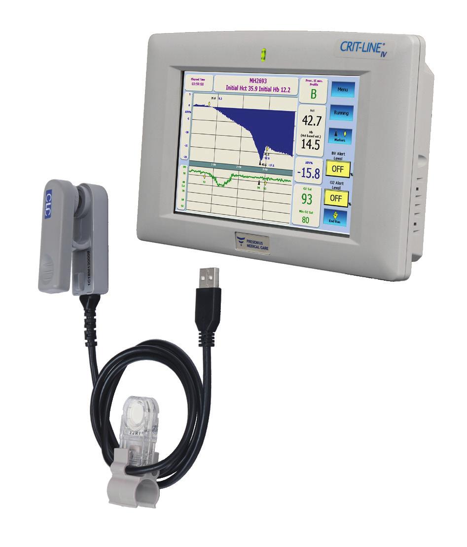
2 Indications for Use: The Crit-Line monitor is used to non-invasively measure hematocrit, oxygen saturation and percent change in blood volume. The sensor clip measures hematocrit, percent change in blood volume and oxygen saturation in real time for application in the treatment of dialysis patients with the intended purpose of providing a more effective treatment for both the dialysis patient and the clinician. Based on the data that the monitor provides, the clinician/nurse, under physician direction, intervenes (i.e. increases or decreases the rate at which fluid is removed from the blood) in order to remove the maximum amount of fluid from the dialysis patient without the patient experiencing the common complications of dialysis which include nausea, cramping and vomiting. The Crit-Line blood chamber is a sterile, single use, disposable, optical cuvette designed for use with the Crit-Line sensor clip during acute and chronic hemodialysis therapy to non-invasively measure hematocrit, percent change in blood volume and oxygen saturation. The blood chamber is connected between the arterial bloodline and the dialyzer within the extracorporeal circuit during the hemodialysis treatment. Caution: Federal (US) law restricts these devices to sale by or on the order of a physician. Note: Read the Instructions for Use for safe and proper use of these devices. For a complete description of hazards, contraindications, side effects and precautions, see full package labeling at
3 Training Guide Introduction The Crit-Line Monitor Training Guide (Guide) is solely for training skilled healthcare professionals in the use of the Crit-Line monitor. This Guide is intended to be used as a companion to the Crit-Line Monitor User s Guide (User s Guide, P/N CL ), which contains detailed instructions for all machine functions. This Guide is designed to be flexible, taking into account the various experiences and skill level of the participants, the number of participants and the amount of time available for training. Similarly, this Guide recommends that participants have the opportunity to use the Crit-Line monitor during a patient dialysis session to enhance the training experience. This hands-on experience may occur at the time of training or over several days depending on the facility, shift schedules, etc., and should be tailored to each facility, participant and situation. Each facility will determine who will participate in the Crit-Line Monitor In-Service Training. It is anticipated that participants will include nurses, patient care technicians (PCTs), and physicians, with nurses being the primary focus of the In-Service Training. 1
4 Training Prework: In order to ensure that participants have the clinical background needed to interpret the Crit-Line monitor data, all nurses must complete the following online course prior to attending this training: Completion of the prework by other participants (e.g., PCTs) is at the discretion of each facility. Training Resources: In addition to this Guide, the following materials are incorporated into the Crit-Line Monitor In-Service Training: Crit-Line Monitor User s Guide Crit-Line Monitor Participant Workbook (P/N ) Crit-Line Monitor Reference Guide (P/N ) Crit-Line Monitor Quickstart Guide (P/N ) Icons and Descriptions: The following icons are used in this Guide to provide direction and clarity: Icons and Descriptions Instructor explanation and demonstration Facilitation tips and supplemental comments A Warning or caution 2
5 Training Guide Training Timeline 4-6 Weeks Prior to Training: Schedule participants and communicate pre-work requirements. 4 Weeks Prior to Training: Ensure that the following are available at the facility for training: - Crit-Line monitors, sensor clips and blood chambers - Crit-Line Monitor Training Guide - Crit-Line Monitor User s Guide - Crit-Line Monitor Participant Workbook (one per participant) - Crit-Line Monitor Reference Guide (extra copies for facility) 2 Weeks Prior to Training: Ensure that prework has been accessed and that participants are on track to complete the prework ahead of the scheduled training day. 1 Week Prior to Training: Confirm receipt of training materials Confirm participant attendance Day of Training: Plan to arrive early to ensure that the Crit-Line monitor is available for use and the blood chambers have been located. Training Guide Note This Guide s training is limited to the features and operation of the Crit-Line monitor and does not cover other critical dialysis-related subjects or related clinical theory. Neither this Guide, nor the In-Service Training, are intended to compromise or replace specific policies and procedures of hemodialysis providers or the treatment prescriptions of physicians. Fresenius Renal Technologies and its affiliates make no recommendations and assume no liability for the policies and procedures established in hemodialysis providers clinics for hemodialysis treatments. 3
6 Training Topics Welcome/getting Started Distribute and introduce the Crit-Line Participant Workbook Introduce the Crit-Line Monitor User s Guide Crit-Line Monitor Overview Monitor features Setup Blood chamber placement Sensor clip Preparation for Treatment Verify accuracy routine Initiation and Termination of Treatment Sensor clip attachment Start run BV alert level O 2 alert level Markers Ending a treatment Printing/downloading treatment results Cleaning Troubleshooting Alarms Review Profiles A, B and C Hands-on Demonstration Facility patient treatment area 4
7 Training Guide Notes: 5
8 Getting Started Welcome Participants Ensure that all participants have registered their attendance on the sign-in sheet. Solicit the cooperation of the participants to ensure a good learning experience, including, limiting cell phone usage to breaks only. Set Expectations: Timing of training (approximate length of classroom experience) Timing and process for actual demonstrations o It is recommended that demonstrations begin during a shift change. Depending upon the number of participants, there may need to be several demonstrations in order for everyone to have the opportunity to see the actual Crit-Line monitor in operation. Distribute and Introduce the Participant Workbook Give participants a few minutes to familiarize themselves with the Participant Workbook. Let the participants know that it is their personal workbook to keep and encourage them to take notes for future reference. Introduce the Crit-Line In-Service Training Checklist, located on page 25 in this Guide and in the Participant Workbook and encourage participants to check topics off as they are covered during the training. Introduce the Crit-Line Monitor User s Guide Remind participants that the User s Guide provides a reference for use of the Crit-Line monitor and should be available in the facility at all times. 6
9 Training Guide Crit-Line Monitor Overview Review the physical features and setup of the Crit-Line system, and point out specific items listed below. Features Sensor clip USB Connector Zigbee Radio (optional) Verification Filter Crit-Line Blood Chamber Power Supply Adapter Power Connection Serial Com 1 Power Switch Power Supply Jack Setup and Power On Attach blood chamber and check position o If demonstrating in the classroom, use sensor clip, blood chamber and dry dialyzer. o If demonstrating on the patient treatment floor, use actual machine. Prime (per unit procedure) 7
 Sensor")
10 Crit-Line Monitor Crit-Line Blood Chamber USB Connection Verification Filter Wireless ZigBee Radio (optional) Sensor Clip 8
 Serial Ports (only Com 1 is active) USB Ports (both active) Power Switch")
11 Training Guide Mount Bracket Com 2 Com 1 Power Supply Jack Ethernet Ports (not active) Serial Ports (only Com 1 is active) USB Ports (both active) Power Switch 9
12 Preparation for Treatment Review the steps required to prepare for a patient treatment using the Crit-Line monitor, being sure to point out specific features as detailed below. Crit-Line Monitor Verification Filter The sensor clip features a verification filter unique to each sensor device. The verification filter is used to periodically verify the accuracy of the sensor clip. The sensor verification filter is attached to the sensor clip s USB cable. The sensor clip should be securely attached to the verification filter when it is not in use. When the sensor clip is stored on its verification filter, the Crit-Line monitor automatically verifies the accuracy of the sensor clip prior to entering patient run mode. If the sensor clip is not stored on the Crit-Line verification filter, it must be manually verified at least once per month. 10
13 Training Guide Verifying the Sensor Clip Verifying Accuracy on the Sensor Selecting the Verify Accuracy button from the Main Menu screen allows the user to perform a manual verification of accuracy on the sensor clip. Note: In most cases, it is not necessary to perform a manual verification. If the sensor clip is placed onto the verification filter, the Crit-Line monitor will automatically perform a verification test once per day, and the date of the most recent successful verification will be displayed below the Verify Accuracy button. Note: The user cannot access the Patient Run Menu screen until a successful verification has taken place. Note: If the verification fails two or more times, the option is given to perform a field calibration. Follow these basic steps to manually verify accuracy: 1. Place sensor clip on verification filter. 1. Hold the sensor clip such that one side is held by the index finger and the other side is held by the thumb. Squeeze the clip to spread the sensor elements apart. 2. Place the sensor clip over the verification filter such that the sensor elements cover the middle portion of the verification filter. 3. Release the sensor clip to allow the sensor elements to sit on the verification filter. 4. Make certain that the sensor clip has locked securely into place on the verification filter by noting the audible and tactile click. 2. Press the Verify Accuracy button. Once the Verify Accuracy button is pressed, the following screen will appear. This screen will remain for approximately ten seconds. 11
14 Verifying the Sensor Clip 3. Verify passed. If successful, the following screen will appear. Press the OK button to return to the Main Menu screen. At this point the verification is complete and no further action is required. 4. Verify failed. If the verification failed, the following screen will appear. Follow these basic steps to address a failed verification of accuracy: 1. Ensure that the sensor clip is properly seated on the verification filter. Refer to page 11 for detailed instructions on how to properly place the sensor clip onto the verification filter. 2. Ensure that the verification filter is clean of any foreign material and that the surface is not scratched or damaged. Refer to page 20 for cleaning instructions. 3. Press the Verify button to repeat the verification of accuracy. If successful, the following screen will appear. Press the OK button to return to the Main Menu screen. At this point the verification is complete and no further action is required. 12
15 Training Guide Verifying the Sensor Clip 4. If the verification fails again, the following screen will appear. At this point the user may do one of the following: Repeat the verification. Refer to step 12. Verify failed sub-steps 1 through 3 on the previous pages (11-12). Perform a field calibration. Refer to the Field calibration on the sensor clip section below. Change the sensor clip. Refer to Replacing the sensor clip in the User s Guide. Cancel the verification process by pressing the Cancel button. Note: If the operator chooses to cancel a failed verification process, the clip will not be available for patient treatment monitoring. Field Calibration on the Sensor Clip Selecting the Field Calibration button from the Verify failed menu screen allows the user to perform a field calibration on the sensor clip. Note: This option will only be made available if the verification of accuracy fails multiple times. Follow these basic steps to perform a field calibration: 1. Press the Field Calibration button. Once the Field Calibration button is pressed, the following screen will appear. 13

16 Verifying the Sensor Clip 2. Press the Filter ID button Once the Filter ID button is pressed, the Enter Filter ID screen will appear. 1. Enter the verification filter ID using the onscreen keypad. As characters are entered, they will display in the top window. The filter ID is located in the middle of the verification filter, as shown below: he middle of the verification filter, as sh 2. Once the verification filter ID has been entered, press the Save button. 3. Press the OK button Once the OK button is pressed, a verification of accuracy will be performed as described in the Manually Verify Accuracy on the sensor section. Note: If the verification of accuracy continues to fail, the sensor clip is no longer suitable for clinical use and should be replaced. 14
17 Training Guide Initiation and Termination of Treatment Review key steps for initiating and terminating treatment on the Crit-Line monitor, being sure to include the following topics: Connecting the Crit-Line Blood Chamber Follow these basic steps to attach the disposable blood chamber to the dialyzer during the extracorporeal bloodline setup before priming the bloodlines. Note: The Crit-Line blood chamber is tinted blue in color and must be used with the Crit-Line monitor. Note: The blood chamber is intended for single-use only. A new sterile blood chamber must be used for each monitoring session. 1. Inspect blood chamber and packaging. Inspect the blood chamber and its sterile package prior to use. Refer to the blood chamber package label to ensure that the blood chamber sterilization has not expired. A Warning: Do not use the blood chamber if its package has been opened or its sterility has otherwise been compromised prior to use. The viewing area of the disposable blood chamber should be kept clean and free of obstruction. 2. Connect blood chamber to dialyzer. Remove the blood chamber from its sterile package and aseptically attach the red connector to the arterial port of the dialyzer. Make sure the connection is tight. 3. Continue setting up the bloodlines. Continue to set up the bloodlines as per the manufacturer s recommendations. Note: When connecting the arterial bloodline to the blood chamber (not the dialyzer), hold the blood chamber securely in one hand and aseptically attach the dialyzer end of the arterial bloodline with the other hand. Be careful that you do not cross-thread the connection. The connection of the blood chamber to the arterial bloodline must not leak. Note: Make sure that no air is in the blood chamber after priming. The accuracy of the hematocrit and oxygen saturation readings may be adversely affected if there is any air present in the blood chamber. 15

18 Initiation and Termination of Treatment Connecting the Sensor Clip to the Blood Chamber Follow the steps below to attach the sensor clip to the blood chamber before connecting to the patient s vascular access: 1. Pinch open the sensor clip. Hold the sensor clip such that one side is held by the index finger and the other side is held by the thumb. Squeeze the clip to spread the sensor elements apart. 2. Attach sensor clip onto the blood chamber. A Caution: Before attaching the sensor clip, check carefully for leaks at the connections between the blood chamber and the dialyzer, and the blood chamber and the arterial bloodline. Improper attachment of the arterial bloodline to the blood chamber can cause blood or saline to leak onto and into the sensor clip. This can damage the sensor clip. Place the sensor clip over the blood chamber so that the optical sensor covers the lens of the blood chamber. Release the clip to allow the optical sensor to seat on the viewing area of the blood chamber. Make certain that the sensor clip has locked securely into place on the blood chamber by noting the audible and tactile click. Ensure that the sensor clip is perpendicular to the top of the dialyzer and cannot be easily rotated up or down while attached to the blood chamber to ensure its proper placement. Note: Make sure that the sensor clip is properly in place before treatment initiation. If the sensor clip is not properly seated on the Crit-Line blood chamber, the accuracy of the hematocrit and oxygen saturation readings may be adversely affected. 3. Check for proper blood flow before selecting Start Run. When starting the blood pump at the beginning of treatment, visually verify proper blood flow in the extracorporeal circuit, including the blood chamber, before selecting Start Run. 16

19 Training Guide Initiation and Termination of Treatment Start Run Explain Blood Volume (BV) Alert Level and O 2 Alert Level Function Set initial BV alert level limit BV Alert Level button sets the BV Alert Level. When the current BV% change drops below the set BV Alert Level, the Crit-Line monitor will display the alert message Rel. Blood Volume Low. This message will occur until the user changes the level or sets the BV Alert Level to OFF. To set the BV Alert Level, select the BV Alert Level button and enter the desired value using the arrow (up or down) keys until the desired level is displayed, then press the CONFIRM key. Press CANCEL to return to the original setting. Press the Disable button to set the BV Alert Level to off. The BV Alert Level can be set from -1% to -25%, or 0 for OFF. The default setting is OFF. The BV alert level is drawn as a blue dotted line across the BV graph. In order to set a BV Alert Level, blood must first be sensed. Navigate Screens Setting the Crit-Line Monitor Graph The default Crit-Line monitor graph is the blood volume graph. To change the graph, push the MENU button to enter the Patient Run Option Menu Screen. From this screen, you can choose the BV or Hct graph option by selecting the appropriate button. Reading Graphs on the Crit-Line Monitor Screen The Crit-Line monitor screen can display either blood volume or hematocrit on the upper graph depending on user settings. The default setting is blood volume. On the lower graph, the oxygen saturation graph is displayed. Graphing of the data begins after the user selects Start Run and the sensor clip reads blood sensed and the hematocrit has been stable for sixty seconds. Graphs are displayed for a minimum of four hours (default) and will rescale to accomodate treatments longer than four hours. The graphs are resized larger during the treatment depending on the min/max values and alert levels. Assess Data Points o Hematocrit (Hct) o Blood volume change (%) o Minimum oxygen saturation Adjust BV Alert Level (if necessary) Change Profile Display 17
20 Initiation and Termination of Treatment Setting an Event Marker Selecting the Marker button displays a menu to insert an event marker on the ΔBV%, Hct and O 2 Sat graphs. 1. Press the Marker button. Once the Marker button is pressed, the event marker selection screen will appear. 2. Select event Marker type. Press the Symptom button to display a yellow diamond t on the graphs. Press the Intervention button to display a black triangle s on the graphs. Press the Cancel button to return without selecting an event marker. Note: To prevent clutter on the graphs, the time between entering a marker must be at least ten minutes apart. If events occur more frequently than ten minutes, the operator must document it manually in the patient treatment record. Note: Adding an event marker encodes the markers in the patient treatment history file. These markers appear on each profile screen in the printed graphs. Note: If the clinical event being marked is a patient symptom, the operator selects the Symptom button. A yellow diamond t on the graphic display indicates an event related to a symptom. Note: If the clinical event being marked is an intervention to prevent a potential symptomatic response from the patient, the operator selects the Intervention button. A black triangle s on the graphic display indicates an event related to an intervention. 3. Confirm selection. Once the marker has been selected, the event marker confirmation screen will appear. 18
21 Training Guide Initiation and Termination of Treatment Ending a Patient Treatment Monitoring Session 1. Press the End Run button. Once the End Run button is pressed, the End Patient Run option menu will appear. 2. Make selection. Press the Print report button to terminate and print the Crit-Line monitor patient treatment monitoring session. Press the Do not print report button to terminate the Crit-Line monitor patient treatment monitoring session without printing. Press the Cancel button to return to the Crit-Line monitor patient treatment monitoring session. Note: When a Crit-Line monitor patient treatment monitoring session is ended, either by printing or not printing, the system returns to the Patient Run menu. 3. Remove sensor clip from blood chamber. When the treatment is complete, pinch the sensor clip to spread the sensor elements apart and gently remove the sensor clip from the blood chamber. Store the sensor clip by securing it to its verification filter, which is attached to its USB cable. Discard the disposable blood chamber with the rest of the bloodlines following appropriate hazardous waste handling requirements. 19
22 Initiation and Termination of Treatment Crit-Line Monitor Care Cleaning and Disinfecting the Crit-Line Monitor The Crit-Line monitor is a sensitive electro-optical device. Use care when cleaning the exterior of the Crit-Line monitor, the sensor clip and verification filter so as not to damage them. The exterior of the sensor clip, verification filter, and the Crit-Line monitor should be cleaned after every treatment. These can all be cleaned with dilute bleach solution (1:100) or other suitable hospital disinfectant. Freshly prepared dilute bleach solution (1:100) is currently recommended by the Center for Disease Control as a suitable disinfectant for the hepatitis virus. Because surface contamination is the general mode of transmission for this type of virus, thorough cleaning of the exterior is essential. A Caution: Wipe the Crit-Line monitor and sensor clip with a cloth dampened with the cleaning solution, Do not spray the solution on the Crit-Line monitor or sensor clip. Do not immerse the sensor clip in any type of liquid. If liquids infiltrate the clip, they will damage it. Caution: Do not use abrasive materials or solvents to clean the Crit-Line monitor, sensor clip or verification filter. Doing so may cause damage. Caution: Be careful not to scratch or damage the verification filter. If the verification filter is scratched or damaged, it may cause the sensor clip to fail verification of accuracy. Caution: If the Crit-Line monitor or sensor clip becomes contaminated with blood, it must be thoroughly disinfected before the next treatment. Freshly prepared dilute bleach solution (1:100) or surface disinfectants such as Cavicide or Envirocide are recommended. Sensor Device Disposal If the sensor clip continues to fail verification of accuracy, even after recalibration, it is no longer suitable for clinical use. Disinfect the sensor clip before disposing it in accordance with U.S. federal regulations and appropriate state and local laws. 20
23 Training Guide Troubleshooting It is important that participants are able to effectively troubleshoot operating alarms as well as treatment results. Review the following resources and steps: Introduce and Explain Common Patient Profiles: BV Profile A BV Profile B BV Profile C Oxygen saturation Points to Consider When Evaluating Patient Profiles: Was the treatment started correctly? Is Hct 30? What was it the last treatment? What is the O 2 saturation? What is the patient s access type? Does the patient need oxygen? Is the BV alert level set? Highlight Common Technical Errors: Did not start properly Setup incorrectly Lab differences between the Crit-Line monitor hematocrit and lab hematocrit Not printing Continue working with alarms and troubleshooting during the hands-on demonstration. 21
24 Wrapping Up/Hands-on Demonstration Prior to Continuing the Training: Point out the In-Service Training Evaluation, located in the Participant Workbook, and ask participants to complete it at the end of the training. o Completing the evaluation is optional. o Provide the fax number of your manager so that participants can return the evaluation directly (a blank space is provided on the form for the fax number). o If the form is returned to the trainer, review and distribute internally as directed by your manager. If applicable, designate a super user to be the point person for the facility post-training. Conduct the hands-on demonstrations so that each participant has an opportunity to see the Crit-Line monitor in use during a patient treatment. If possible, work with patients who have a more difficult situation to allow for greater opportunities to reinforce intervention learnings. After concluding the hands-on demonstrations, complete the In-Service Training Checklist, sign and return to the facility contact. Conduct Exit Interview with Facility Manager: Determine if additional follow-up and support is needed for the unit; place on the call list as needed. Explain to staff what to expect during follow-up calls and record any additional information. For 24-hour technical and clinical support, facilities may contact
25 Crit-Line Monitor In-Service Training Sign-in Sheet Training Guide Facility Name: Date: Instructor: Attendees Note: Signatures indicate attendance only, not competence or expertise. 1. Print Name Signature Title
26 24
27 Training Guide Crit-Line Monitor In-Service Training Checklist Facility Name: Date: Address: City: State: Zip: Contact: Phone: Instructor: Title: Training Topics: Topics may be modified to accommodate the specific policies and procedures of the unit being trained. Checks indicate topics reviewed during In-Service Training; no representation is made regarding participant competence or expertise. Crit-Line Monitor Overview Sensor Clip Features Setup and Power on TRAINING TOPICS Ending Treatment Print/Download Results Cleaning Preparation For Treatment Crit-Line Monitor Verification Filter Calibrating the Sensor Clip Verify Accuracy Alarms and Troubleshooting Profiles A, B and C Technical Errors Initiation of Treatment Fix Sensor Clip Attachment Connecting the Sensor Clip to the Crit-Line blood chamber Start Run BV Alert Level Reading Graphs on Crit-Line Monitor Screen Marking an Intervention Instructor s Signature: 25
28 26
29 Training Guide Appendix 1. Case Studies (All case studies are for educational purposes only.) 2. Fluid Distribution Model 3. Frequent Asked Questions 27
30 Case Study: Patient #1 Note: The Crit-Line Monitor Participant Workbook has actual screen shots, patient history and problems. Learning objectives and answers are only in this Guide. Learning Objective: Identify when treatment has been started incorrectly. Patient History: Patient #1 is a 43-year-old male with an AV fistula; he dialyzes M/W/F for three hours and thirty minutes. The patient has gained 2.3 Kg since his last treatment. BP 130/70, pulse 70, respirations 18 and regular. He has no edema noted, lungs clear to auscultation. Renal failure is secondary to application of contrast media. Problem: Treatment was started and the patient quickly dropped into a negative profile. Use the patient history and the Crit-Line monitor data to answer the following questions: 1. Did they initiate the treatment according to operating instructions? No. The blood volume curve immediately went negative. All treatments should start at a blood volume change of 0%. 2. What may have been the cause of the immediate drop in blood volume at the beginning of the treatment? Incorrect setup of the system, for example: saline in the bloodline, air in the blood chamber or perhaps a temporary stoppage of the blood pump. 3. What is the O 2 saturation reading and is the reading reasonable based on the access type? The O 2 Sat reading is 93%, which is a typical value based on the access type of this patient (AV fistula). 4. What is the patient profile at 20 minutes? Profile B. 5. Were BV and O 2 Alert Levels set? If yes, what are these limits? Yes. The BV Limit -15%, O 2 Limit 89%. 6. Based on your assessment, would you recommend any interventions? Yes. If a false start is observed (i.e., the BV% change does not start at 0%) turn the Crit-Line monitor OFF and back ON and start the treatment again. Remember to ensure that all of the saline prime has been pumped out of the extracorporeal tuning prior to starting a patient run. 28
31 Training Guide Case Study: Patient #2 Learning Objectives: Work with patient in Profile A who has a history of fluctuating post weight. Assess for plasma refill during the last 10 minutes of the treatment Patient History: Patient #2 is a 67-year-old female with R subclavian CVC access used for dialysis while her L AV fistula develops. She dialyzes T/Th/S for three hours and forty-five minutes. She has gained 3.0 Kg since her last treatment, but is only 1.2 Kg above her estimated dry weight. She has been complaining that her weight is always different post treatment depending on her caregiver. Looking back through her treatment records, you notice this is true. Her weight fluctuates by 1.5 Kg. She is an insulin-dependent diabetic patient that has CKD 5 secondary to years of not controlling her diabetes. BP 148/90, pulse 100, respirations 24, mild peripheral edema, assessment shows lobes are clear, bases are full. Problem: Use the patient history and the Crit-Line monitor data to answer the following questions: 1. Was the treatment started correctly? Yes. The BV % change was 0 at the beginning of the treatment. 2. What profile is displayed in the first hour and what profile is displayed between the first and the second hour? Profile A in the first hour, then Profile B in the second hour. 3. What intervention likely occurred with the first intervention marker? Increase in UF Goal to get the Profile A to change to Profile B. 4. What does the second intervention marker indicate? Reduce UF minimum to prevent a steep slope from continuing, or perform a plasma refill check. 5. What does the directional change at the second arrow represent? Plasma refill is present. 6. What is the O 2 saturation reading and is the reading reasonable based on the access type? The O 2 Sat reading is 60%, which is a typical value based on the access type of this patient (CVC). 29
32 Case Study: Patient #3 Learning Objective: Show a Profile B from the beginning to the end of the treatment; Typical O 2 saturation for access type. Patient History: Patient #3 is an 89-year-old male with a L Internal Jugular (IJ) CVC line. He is scheduled for dialysis M/W/F for three hours. He gains 1.5 Kg between treatments and prides himself in his excellent compliance to all recommendations from his dialysis team. BP 120/80, pulse 68, respiration 20, no peripheral edema, clear lungs and no complaints. Patient history only shows very moderate weight gain between treatments and patient usually is at his dry weight post treatment. Only the fluid gained between treatments has to be removed. Problem: Use the patient history and the Crit-Line monitor data to answer the following questions: 1. Did they initiate treatment according to operating instructions? Yes. 2. Based on your assessment, is this a reasonable profile for this patient? Yes. 3. What is the O 2 saturation reading and is the reading reasonable based on the access type? The O 2 Sat reading is 66%, which is a typical value based on the access type of this patient (CVC) O 2 saturation is appropriate for a central venous catheter. 4. Were BV and O 2 Alert Levels set? If yes, what are these limits? Yes. The BV Limit -15%, O 2 Limit 59%. 30

33 Training Guide Case Study: Patient #4 Learning Objective: Show patient with Profile C with low O 2 saturation. Participants recognize the opportunity to administer O 2 according a physician s prescription or clinic policies and procedures and decrease UF goal to return patient to Profile B. Patient History: Patient #4 is a 72-year-old male with R IJ CVC access. He dialyzes T/Th/S for three hours. He has an extensive cardiovascular history, including stent placement, previous bypass surgery, and low cardiac output. He is prescribed multiple blood pressure medications, but sometimes forgets to take them at the right time. He arrived for treatment 3.5 Kg over his last post weight and 5.0 Kg away from target weight. BP 90/46, pulse 88 irregular, respirations of 20. His lungs are clear and no edema noted. Problem: Use the patient history and the Crit-Line monitor data to answer the following questions: 1. Did they initiate treatment according to operating instructions? Yes. 2. What profile is being displayed in the first hour of treatment? Profile C. 3. Is the profile in the first hour reasonable for this patient? No, the patient profile was greater than -6.5% per hour. Monitor the patient more closely for potential intradialytic events. 4. What is the O 2 saturation reading and is the reading reasonable based on the access type? The O 2 Sat reading is 59%, which is below the typical value based on the access type of this patient (CVC). 5. In your assessment, do you think the physician needs to consider changes for the next treatment? Yes. Please consult with the physician regarding future treatments in respect to frequency and treatment duration. 6. Was refill present? Yes. 31
34 Case Study: Patient #5 Learning Objective: Show a patient in Profile A, who has low fluid gain, a lot of residual urine output and does not need additional ultrafiltration. Patient History: Patient #5 is a 54-year-old female with L AV fistula. She dialyzes M/W/F for four hours after she gets off work. She has 0.5Kg weight gain since her last treatment. As you review her chart you note that she rarely gains much weight between treatments. You notice she brought in 2 jugs for her 24-hour urine collection. Her BP is 110/68, pulse 98, and respirations 16, lungs are clear, no edema noted. She is dialyzed at minimum UF. Problem: Use the patient history and the Crit-Line monitor to answer the following questions: 1. What profile does this patient graph exhibit? Profile A. 2. What profile would you expect for this patient given her history and treatment parameters? Profile A seems reasonable for this patient due to a low UF Goal and high urine output. 3. What is the O 2 saturation reading and is the reading within typical range based on the access type? The O 2 Sat reading is 94%, which is a typical value based on the access type of this patient (AV Fistula). 4. Were BV and O 2 Alert Levels set? If yes, what are these limits? Yes. The BV Limit -3%, O 2 Limit 89%. 32

35 Training Guide Case Study: Patient #6 Learning Objective: Work with situation where BP, Pulse and MAP are elevated, but not enough for alarm; Profile A at treatment start with borderline O 2 saturation. Manage patient weight by increasing UF goal and consider administering oxygen. Convert from Profile A to Profile B and continue to monitor. Patient History: Patient #6 is a 48-year-old female patient that has L AV fistula. She is scheduled for T/Th/S treatment for four hours. She began dialysis nine months ago and continues to use the same dry weight. Her BP is 158/98, pulse 102, respirations 24, peripheral edema noted before and after treatment, lungs are not clear. Due to clinical signs of over hydration, the physician ordered a reduction in dry weight. Problem: Use the patient history and the Crit-Line monitor data to answer the following questions: 1. Was the treatment initiated correctly? Yes. The BV % change started at 0%. 2. Does the profile shown seem reasonable for this patient? Patient initially shows an Profile A which converts into a Profile B after two interventions. These interventions seem reasonable in order to remove the excess fluid. 3. In your assessment, was the O 2 Saturation for this patient adequate throughout the entire treatment? No. The O 2 Sat drops into the 80s on two occasions, which is low for an AVF patient. 4. Did the patient convert to a different profile following the first intervention? No. The patient remained in Profile A. 5. What interventions were possibly made at the first intervention marker? The UF Goal may have been increased and O 2 may have been given. 6. Did the patient convert to a different profile following the second intervention? Yes. The patient converted to Profile B. 7. Was refill observed at the end of the treatment? Yes, but since no marker has been entered, it is hard to tell if a refill check was intended or not. Always make sure to enter an intervention marker when performing a refill check. If patient shows signs of edema despite being at dry weight, consider lowering the dry weight. 33

36 Fluid Distribution Model Intracellular fluid (without blood cell fluid) Interstitial fluid Blood Circulating BV Peripheral BV Ultrafiltration Dialysate osmolarity Dialysate temperature 34
37 Training Guide Frequently Asked Questions 1. What are the three main measurements that are measured by the sensor clip? Hematocrit, oxygen saturation and percent change in intravascular blood volume. 2. How does the sensor clip make its measurements? The sensor clip shines a light through the lens of a blood chamber that is placed between the arterial bloodline and the inlet port of the dialyzer. The other end of the sensor clip detects the level of absorption and scattering of the red light as it is transmitted through the patient s blood, which flows through the blood chamber. 3. How does the sensor clip verify that it is measuring accurately? Each sensor clip has its own verification filter that is used to periodically verify its accuracy. This filter is attached to the sensor clip s USB cable. 4. How often should you verify accuracy on the verification filter? When the sensor clip is stored on the verification filter, the Crit-Line monitor automatically verifies the accuracy prior to entering Patient Run Mode. When the sensor clip is not stored on the verification filter, it must be verified once per month. 5. Can the blood chamber be used more than one time? The blood chamber is intended for single-use only. 6. After priming the circuit, what should I look for before connecting the sensor clip to the blood chamber? Make sure that no air is in the blood chamber after priming. Any air present in the blood chamber will cause the hematocrit reading to be inaccurate. 7. What are the default sensor clip graphs displayed on the Crit-Line monitor? The blood volume and oxygen saturation graphs are the default screens displayed. 8. What are the other screens that can be displayed? The blood volume graph can be switched to a hematocrit graph. 9. When the does sensor clip start to take measurements? Graphing of the data begins after the user selects Start Run and the sensor clip reads blood sensed and the hematocrit has been stable for 60 seconds. 10. How are the two types of event markers displayed? The symptom marker is displayed as a yellow diamond. The intervention marker is displayed as a black triangle. 35
38 FAQs (continued) 11. What is the profile that is displayed? The profile that is displayed is the average percent change in blood volume (ΔBV%) of the previous 15 minutes of data gathered. If the ΔBV% is -3% per hour, the profile will be displayed as Profile A. If the ΔBV% is >-3% per hour and -6.5% per hour, then the profile will be displayed as a Profile B. If the ΔBV% >-6.5% per hour, the profile will be displayed as a Profile C. 12. What is the estimated HB value that is displayed? The hemoglobin value that is displayed is an estimated measurement based on the measured hematocrit. 13. How is percent change in blood volume calculated? The percent change in blood volume is calculated from the following equation: ΔBV% = {(H 2 /H 1 )-1} X 100 H 2 = Initial Hct H 1 = Current Hct 14. What is the default BV Alert Level? The default BV Alert Level is OFF but will be drawn as a blue dotted line across the BV graph once a BV alert value has been entered. 15. What is the default O 2 Sat Level? The O 2 Alert Level default is OFF but can be set from 45 to Can you print out the treatment profiles at the end of a treatment? Yes, treatment profiles can be printed at the end of a treatment. Additional hardware and software are necessary in order to print patient profiles. Technical Support can be reached at How do you clean the sensor clip? The exterior of the sensor clip and the verification filter should be cleaned after every treatment. These can be cleaned with the standard diluted bleach solution (1:100). Wipe the sensor clip clean with a cloth dampened with a cleaning solution; do not spray the solution directly onto the sensor clip or immerse the sensor clip into any type of liquid. 18. Can the sensor clip still be used if it continues to fail verification? No, if the sensor clip continues to fail verification, it is no longer suitable for clinical use unless it can be re-calibrated (see User s Guide). 19. What do I do if a sensor clip fails to calibrate? The sensor clip must be taken out of service. Contact Technical Support at
39 Training Guide 37
40 Fresenius Renal Technologies, a division of Fresenius Medical Care North America 920 Winter Street Waltham, MA Customer Service: Technical Support: , Fresenius Medical Care, All Rights Reserved. Fresenius Medical Care, the triangle logo, Fresenius Renal Technologies, Crit-Line and CLiC are trademarks of Fresenius Medical Care Holdings, Inc., and/or its affiliated companies. All other trademarks are the property of their respective owners. P/N Rev A 12/ T HEMODIALYSIS MACHINE WITH sensor DEVICE TRAINING GUIDE
2008T Hemodialysis Machine with CLiC Device Training Guide
 2008T Hemodialysis Machine with CLiC Device Training Guide 2008T Hemodialysis Machine with CLiC Device Training Guide Indications for Use: The CLiC device is used with the 2008T hemodialysis machine to
Indications for Use: Caution: Note:
 IV 1 2 IV This reference is to be used in conjunction with the Crit-Line IV Monitor User s Guide (P/N CL80050002). Refer to the User s Guide for a complete description of alerts, warnings, cautions, and
Contacts. Quick Start Guide
 Contacts Clinical Support Specialist: Phone: Cell Phone: Email: Fresenius Renal Technologies A division of Fresenius Medical Care North America 920 Winter Street Waltham, MA 02451 Technical Service Customer
AQUADEX FLEXFLOW SYSTEM QUICK REFERENCE GUIDE
 AQUADEX FLEXFLOW SYSTEM QUICK REFERENCE GUIDE AQUADEX FLEXFLOW SYSTEM DISCLAIMER The quick reference guide is not intended to replace CHF Solutions, Inc. Aquadex FlexFlow Direction For Use (DFU). Always
MANITOBA RENAL PROGRAM
 MANITOBA RENAL PROGRAM SUBJECT Fresenius 5008 Preparation for Hemodialysis using the ONLINEplus System SECTION CODE 30.10.02 30.10 Hemodialysis: Equipment and Procedures AUTHORIZATION Professional Advisory
Liberty Handi-Guide. A Patient s Reference to the Most Commonly Asked Questions About the Liberty Cycler
 Liberty Handi-Guide A Patient s Reference to the Most Commonly Asked Questions About the Liberty Cycler This information is not intended to replace the advice or training from your physician or PD Nurse.
Liberty PDx Cycler Handi-Guide
 Liberty PDx Cycler Handi-Guide A Patient s Reference to the Most Commonly Asked Questions about the Liberty PDx Cycler This information is not intended to replace the advice or training from your physician
Liberty Cycler Handi-Guide
 Liberty Cycler Handi-Guide A Patient s Reference to the Most Commonly Asked Questions about the Liberty Cycler This information is not intended to replace the advice or training from your physician or
Liberty Handi-Guide A Patient s Reference to the Most Commonly Asked Questions About the Liberty Cycler
 0408 Liberty Handi-Guide_update_Layout 1 11/22/13 4:53 PM 11/22/13 Page 1 Liberty Handi-Guide A Patient s Reference to the Most Commonly Asked Questions About the Liberty Cycler This information is not
AQUARIUS Continuous Renal Replacement Therapy with Regional Citrate Anticoagulation (RCA) Competency
 Competency") Demonstrates an understanding of why RCA has been prescribed Explain the anticoagulation protocol Demonstrate an understanding of potential complications associated with CRRT. Explain potential indications
Demonstrates an understanding of why RCA has been prescribed Explain the anticoagulation protocol Demonstrate an understanding of potential complications associated with CRRT. Explain potential indications
AQUARIUS Continuous Renal Replacement Therapy Competency
 Preparation Explain the procedure to the patient and significant others Prepare the patient. Prepare the environment. Ensure a safe environment for the patient and staff Gather equipment required to Setup
Quiz for Module 2: Aquarius Training (Rev. 1) Lesson 1: Introduction to Aquarius
 Lesson 1: Introduction to Aquarius") Quiz for Module 2: Aquarius Training (Rev. 1) Lesson 1: Introduction to Aquarius page 1 of 2 Name: Date: Score: Instructor: Location: Please circle the correct answers: 1. Select the answer(s) that represent
Quiz for Module 2: Aquarius Training (Rev. 1) Lesson 1: Introduction to Aquarius page 1 of 2 Name: Date: Score: Instructor: Location: Please circle the correct answers: 1. Select the answer(s) that represent
Handi-Guide A Patient s Reference to the Most Commonly Asked Questions About the Liberty Select Cycler
 Handi-Guide A Patient s Reference to the Most Commonly Asked Questions About the Liberty Select Cycler This information is not intended to replace the advice or training from your physician or PD nurse.
HemoCue Hb Procedure Template
 HemoCue Hb 201 + Procedure Template PURPOSE The HemoCue Hb 201 + System is used for the quantitative determination of hemoglobin in blood using a specially designed analyzer, HemoCue Hb 201 +, and specially
Endo-Flush Order # ZUTR30004 OPERATION MANUAL. Zutron Medical, LLC W 98 th St #40-27 Lenexa, KS Phone Fax
 OPERATION MANUAL Zutron Medical, LLC 17501 W 98 th St #40-27 Lenexa, KS 66219 Phone 877-343-5873 Fax 913-967-5944 ZUT-Lab-004-30004 REV. 03312017 Table of Contents 2 Introduction 1. Intended Use 2. Labels,
STANDARD OPERATING PROCEDURES DIVISION OF COMPARATIVE MEDICINE UNIVERSITY OF SOUTH FLORIDA
 STANDARD OPERATING PROCEDURES DIVISION OF COMPARATIVE MEDICINE UNIVERSITY OF SOUTH FLORIDA SOP#: 1157.1 Date Issued: 05/14 Date Revised: 5/15 Page 1 of 6 TITLE: SCOPE: RESPONSIBILITY: PURPOSE: SurgiVet
Department of Laboratories St. Louis, MO ISSUE DATE: June 2007 REVISION DATE: July 2010 REVIEWED DATE: May 2017 PRINCIPILE:
 Page 1 of 6 PROCEDURE: HEMOCUE HEMOGLOBIN 201+ ANALYZER ISSUE DATE: June 2007 REVISION DATE: July 2010 REVIEWED DATE: May 2017 PRINCIPILE: The HemoCue B-Hemoglobin 201+ system consists of disposable microcuvettes
WARNING: EXPLOSION HAZARD
 Section 1 Safety 1.1 Instructions for the Safe Operation and Use of the Pulse Oximeter Do not attempt to service the Pulse Oximeter yourself. Only qualified service personnel should attempt any necessary
Liberty Cycler User s Guide
 Liberty Cycler User s Guide Copyright 2011 2015, Fresenius Medical Care All Rights Reserved This document contains proprietary information of Fresenius USA, Inc. d/b/a Fresenius Medical Care North America
Liberty Select Cycler User s Guide
 Liberty Select Cycler User s Guide Copyright 2016, 2017 Fresenius Medical Care All Rights Reserved This document contains proprietary information of Fresenius USA, Inc. d/b/a Fresenius Medical Care North
Liberty PDx Cycler User s Guide
 Liberty PDx Cycler User s Guide Copyright 2014, 2016, Fresenius Medical Care All Rights Reserved This document contains proprietary information of Fresenius USA, Inc. d/b/a Fresenius Medical Care North
1020 Industrial Drive, Orlinda, TN fax
 Operation Manual Ultrafiltration for High Purity Distribution K-A-HPTUF Series 615-654-4441 sales@specialtyh2o.com 615-654-4449 fax TABLE OF CONTENTS Section 1 GENERAL 1.1 Warnings and Cautions... 1 1.2
MANITOBA RENAL PROGRAM
 MANITOBA RENAL PROGRAM SUBJECT Fresenius AquaUNO Reverse Osmosis System; use of SECTION CODE 30.30.04 30.30 Water Treatment AUTHORIZATION Professional Advisory Committee, Manitoba Renal Program Nursing
Astral in AirView: Improving patient care through connectivity. ResMed.com
 Astral in AirView: Improving patient care through connectivity ResMed.com Using Astral in AirView via the ResMed Connectivity Module (RCM) Astral is ResMed s portable, invasive and non-invasive life support
Bante820 Portable Dissolved Oxygen Meter Instruction Manual
 Bante820 Portable Dissolved Oxygen Meter Instruction Manual BANTE INSTRUMENTS CO., LTD Bante820 Portable Dissolved Oxygen Meter 1 Introduction Thank you for selecting the Bante820 portable dissolved oxygen
My CoughAssist. A patient guide to CoughAssist T70. Please visit
 Philips Healthcare is part of Royal Philips Electronics Europe, Middle East, Africa +49 7031 463 2254 How to reach us www.philips.com/healthcare healthcare@philips.com Latin America +55 11 2125 0744 Asia
NanoSight NS300. NanoSight NS300. Operation instructions. Laser Spectroscopy Labs, UCI
 NanoSight NS300 Operation instructions Injection/flushing brief overview: 1. Do not exceed flow of 1 ml per 20 seconds. 2. Inject two 1 ml syringes with nano-pure or DI water. 3. If the water does not
Cardiac Output Simulation for Specific Makes of Monitor. Each injection yields in a time-temperature curve whose area represents the cardiac output:
 Cardiac Output Simulation for Specific Makes of Monitor Theory The measurement of the volume of blood pumped by the heart is a valuable diagnostic tool in the management of patients undergoing major cardiovascular
Oxygen Dialflow Meter. Instructions for Use
 Oxygen Dialflow Meter Instructions for Use 702-0031.12 December 2017 1. Symbols Warning! Caution! Indicates a potentially hazardous situation which, if not avoided, could result in injury to the patient,
CRRT with Prismaflex LEADS TO More Flexibility, Ease of Use and Safety
 CRRT with Prismaflex LEADS TO More Flexibility, Ease of Use and Safety Leading the way Science is changing and so are your requirements For many years, Gambro has focused its efforts on development of
INTERNATIONAL MARKETING. 61, avenue Tony Garnier Lyon France Tel.: 33 (0) Fax: 33 (0)
 Fax: 33 (0)") 97301102.12.03 INTERNATIONAL MARKETING 61, avenue Tony Garnier - 69007 Lyon France Tel.: 33 (0)4 37 28 11 00 - Fax: 33 (0)4 37 28 10 30 www.hospal.com The information contained in this brochure is subject
97301102.12.03 INTERNATIONAL MARKETING 61, avenue Tony Garnier - 69007 Lyon France Tel.: 33 (0)4 37 28 11 00 - Fax: 33 (0)4 37 28 10 30 www.hospal.com The information contained in this brochure is subject
Astral in AirView: Improving patient care through connectivity. ResMed.com
 Astral in AirView: Improving patient care through connectivity ResMed.com This guide will assist you with: Setting up the ResMed Connectivity Module for Astral 2 Troubleshooting the ResMed Connectivity
Prepared By: Lisa McAvoy 28/Nov/17 dd/mmm/yy. Approved By: Veronica Harris-McAllister 30/Nov/17 dd/mmm/yy
 Standard Operating Procedure Spot Monitors SOP Number: SOP-SM-01.1 Category: Lab Process Supersedes: SOP-SM-01 Effective Date: December 1, 2017 Pages 6 Subject: Spot Monitors Prepared By: Lisa McAvoy 28/Nov/17
Operation and Maintenance of the EPV200 Portable Ventilator
 Operation and Maintenance of the EPV200 Portable Ventilator 1 Applications of the EPV200 The EPV200 Portable Ventilator is a gas powered electronically controlled mechanical ventilator, designed to provide
Overview. Front Panel: Keypad and Display
 Overview The GA-200B is an analyzer that integrates a gas sampling system with sensors to measure and display the concentrations of oxygen and carbon dioxide in a sample as the percentage of a gas in the
Blood Parameter Monitoring System 550
 Technical Compendium CDI Blood Parameter Monitoring System 550 An overview of the CDI System 550 and its industry leading technology. CDI System 550 Measures or Calculates 12 Critical Blood Parameters
Pedometer with PC download. Model: FB322 OVERVIEW FRONT VIEW INDEX
 OVERVIEW FRONT VIEW Pedometer with PC download INDEX Model: FB322 Introduction...1 Overview...1 Front view...1 Back view battery compartment...1 LCD screen...1 Getting started...2 Setting the device...2
Heart/Lung Perfusion Packs INSTRUCTIONS FOR USE
 Heart/Lung Perfusion Packs INSTRUCTIONS FOR USE DESCRIPTION A Heart/Lung Perfusion Pack is either a customized tubing pack built to user specifications or a stock tubing pack, designed for use during surgery
Troubleshooting Guide Aquarius
 Low Access Pressure Access pressure has dropped below the lower alarm limit of 0 to - 250mmHg Blood pump is off Blood flow is too low Turn blood pump on Check blood flow rate. Consider increasing the blood
ECHO MANUAL WARNING. L B A ltim e te rs. ECHO is a trademark of LB Altimeters, Denmark
 ECHO MANUAL L B A ltim e te rs ECHO is a trademark of LB Altimeters, Denmark LB Altimeters operates a policy of continuous development Therefore, we reserve the right to make changes and improvements to
MASK INTEGRITY TEST ACCESSORY (MITA) MODEL 8120
 MODEL 8120") MASK INTEGRITY TEST ACCESSORY (MITA) MODEL 8120 QUICK START GUIDE P/N 6006154, REVISION C MAY 2013 Model 8120 Mask Integrity Tester is patented under U.S. Patent No. 8,312,761. Additional patents are pending.
MASK INTEGRITY TEST ACCESSORY (MITA) MODEL 8120 QUICK START GUIDE P/N 6006154, REVISION C MAY 2013 Model 8120 Mask Integrity Tester is patented under U.S. Patent No. 8,312,761. Additional patents are pending.
MP15 Jockey Pump Controller
 Setup and Operating Instructions MP15 Jockey Pump Controller This manual provides general information, installation, operation, maintenance, and system setup information for Metron Model MP15 Jockey Pump
Scoreboard Operator s Instructions MPC Control
 Scoreboard Operator s Instructions MPC Control Some features on the keyboard overlay may not be included on the particular model being operated. Since 1934 Retain this manual in your permanent files 1/21/2011
CONTENTS SPECIFICATIONS GENERAL INFORMATION RECOMMENDED USE OPERATING PRINCIPLE TIPS ON TAKING YOUR BLOOD PRESSURE 3-4 BATTERY INSTALLATION
 IFU SBPMON107 CONTENTS SPECIFICATIONS GENERAL INFORMATION RECOMMENDED USE OPERATING PRINCIPLE TIPS ON TAKING YOUR BLOOD PRESSURE BATTERY INSTALLATION CORRECT POSITION FOR MEASUREMENT POSITIONING THE CUFF
USER MANUAL FLOW SELECTOR PM1000 SAVE THESE INSTRUCTIONS. Federal (USA) law restricts this device to sale by or on the order of a physician.
 law restricts this device to sale by or on the order of a physician.") USER MANUAL FLOW SELECTOR PM1000 SAVE THESE INSTRUCTIONS CAUTION Federal (USA) law restricts this device to sale by or on the order of a physician. RECEIVING / INSPECTION Remove the Precision Medical,
USER MANUAL FLOW SELECTOR PM1000 SAVE THESE INSTRUCTIONS CAUTION Federal (USA) law restricts this device to sale by or on the order of a physician. RECEIVING / INSPECTION Remove the Precision Medical,
Pegas 4000 MF Gas Mixer InstructionManual Columbus Instruments
 Pegas 4000 MF Gas Mixer InstructionManual Contents I Table of Contents Foreword Part I Introduction 1 2 1 System overview... 2 2 Specifications... 3 Part II Installation 4 1 Rear panel connections...
UsER manual for Watersens ph -REDOX
 UsER manual for Watersens -REDOX Cl 8 1 2 6 3 3 7 7 4 4 4 4 Parts List 1 Redox Probe 1 x 2 PH Probe 1 x 5 Tube Weight 2 x 6 Connection Valve 1 x chlorine 3 Chlorine and Pumps 2 x 7 Dosing Valve 2 x 5 5
Read this first. Zetasizer nano series Self installation and Quick start guide MRK825-02
 ! Read this first Zetasizer nano series Self installation and Quick start guide I N S T R U M E N T S MRK825-02 Zetasizer Nano series Self installation and Quick start guide MAN0383 Issue 1.1 July 2007
FAULT CODE TROUBLESHOOTING INDEX
 FAULT CODE TROUBLESHOOTING INDEX 1. Display indicates Change Filters 2. Display indicates Drip Tray Full Continuous Alarm will Sound 3. Display indicates Cold Fault 4. Display indicates Hot Fault 5. Display
Bante821 Portable Dissolved Oxygen Meter Instruction Manual
 Bante821 Portable Dissolved Oxygen Meter Instruction Manual BANTE INSTRUMENTS CO., LTD Bante821 Portable Dissolved Oxygen Meter 1 Introduction Thank you for selecting the Bante821 portable dissolved oxygen
CircuFlow Quick Setup Guide
 CircuFlow 5200 Quick Setup Guide LB04.0001 Rev B 20140314 TABLE OF CONTENTS Setup Therapy Setup Gradient Mode Pressure Mode Lock Device Unlock Device Treatment 03 04 05 08 11 12 13 02 SETUP 01 01 Open
SomnoSuite FAQ. Setup. Calibration 4. What are the calibration requirements for the SomnoSuite? Settings
 SomnoSuite FAQ V1.3 January 2015 Setup 1. How do I connect the SomnoSuite to my oxygen source? 2. Is there a way to speed up the downward movement of the pusher block when setting the empty position? 3.
Procedure 85 Attaching The Humidifier To The Oxygen Flow Meter Or Regulator. Procedure 86 Administering Oxygen Through A Nasal Cannula
 Chapter 12 Respiratory Procedures Procedure 81 Checking Capillary Refill Procedure 82 Using A Pulse Oximeter Procedure 83 Preparing Wall-Outlet Oxygen Procedure 84 Preparing The Oxygen Cylinder Procedure
CDI System 500. Blood Parameter Monitoring System. Continuous blood parameter monitoring for improved blood gas management
 CDI System 500 Blood Parameter Monitoring System Continuous blood parameter monitoring for improved blood gas management The world's most trusted and used continuous in-line blood gas monitor For more
WARNING FOR YOUR SAFETY
 ! OWNER S MANUAL Power Alert AquaLink TRI Controller H0389100 REV A WARNING FOR YOUR SAFETY - This product must be installed and serviced by a licensed electrician in accordance with AS/NZ 3000-2007 and
2008T Hemodialysis Machine Operator s Manual
 2008T Hemodialysis Machine Operator s Manual Caution: Federal (US) law restricts this device to sale only by or on the order of a physician. Note: The most recent version of this manual can be accessed
Fingertip Pulse Oximeter
 Instruction Manual Fingertip Pulse Oximeter Item # 40-810-000 Item # 40-811-000 Item # 40-812-000 Item # 40-813-000 Please read this guidebook completely before operating this unit. Limited Two-Year Warranty
Instruction Manual. Auto Inflate Blood Pressure Monitor
 TM Auto Inflate Blood Pressure Monitor Instruction Manual Features: Fuzzy Logic Technology Auto memory for up to 90 readings One-Touch Operation Easy-to-read Display Date and Time indications AC Adapter
1020 Industrial Drive, Orlinda, TN fax
 Operation Manual Tank Distribution System A-UPT Series 615-654-4441 sales@specialtyh2o.com 615-654-4449 fax TABLE OF CONTENTS Section 1 GENERAL 1.2 Warnings and Cautions... 1 1.2 Theory of Operation...
Experiment B-18 Heart Rate and Coughing
 1 Experiment B-18 Heart Rate and Coughing Objectives To study the changes in heart rate at rest and after coughing. Modules and Sensors PC + NeuLog application USB-200 module NUL-208 Heart rate & pulse
Instructions for Assembly, Installation, and Operation of the Gas Addition Kit Accessory with the CEM Discover Systems
 Corporation Issued: 5/09 P/N: 600104 Rev. 2 Instructions for Assembly, Installation, and Operation of the Gas Addition Kit Accessory with the CEM Discover Systems The Gas Addition Accessory permits the
955730_1 4/17/18. FlowSense Operator s Guide For Gen2 20/20 SeedSense Displays
 955730_1 4/17/18 FlowSense Operator s Guide For Gen2 20/20 SeedSense Displays Contents System Setup and Operation...3 Configuring Monitor for FlowSense...3 FlowSense Setup...4 Liquid Alerts...8 Monitoring
Introduction. Table of Contents. Automatic Wrist Blood Pressure Monitor With Voice-Guided Operation. Model No.: BP5K
 Automatic Wrist Blood Monitor With Voice-Guided Operation Ozeri Customer Service Customer service: 1-877-299-1296 or Email: support@ozeri.com Model No.: BP5K Thank you for choosing an Ozeri Blood Monitor.
Module 2: Aquarius Training
 Module 2: Aquarius Training Module 2: Aquarius Training 1 AQUARIUS TRAINING TABLE OF CONTENTS Lesson 1. Introduction to Aquarius Platinum Lesson 2. Preparing Aquarius Lesson 3. Treatment Mode Lesson 4.
ASAHI Neurovascular Guide Wire
 ASAHI Neurovascular Guide Wire AMK-DT244 Ver.1.00 / 11TS073 Legal manufacturer Consult instructions for use Do not use if package is damaged RX ONLY Caution: Federal (USA) Law restricts this device to
EZ-Boom 2010 Automated Application Control System Quick Reference Card INTRODUCTION
 INTRODUCTION This figure shows the front panel of the EZ-Boom 2010 automated application control system. Status indicator Rate switch Rate Adjustment (Inc/Dec) switch Master switch Boom section switches
TR Electronic Pressure Regulator. User s Manual
 TR Electronic Pressure Regulator Page 2 of 13 Table of Contents Warnings, Cautions & Notices... 3 Factory Default Setting... 4 Quick Start Procedure... 5 Configuration Tab... 8 Setup Tab... 9 Internal
with O 2 Controller Instruction Manual
 14500 Coy Drive, Grass Lake, Michigan 49240 734-475-2200 E-mail: sales@coylab.com www.coylab.com Hypoxic Cabinets (In-Vivo / In-Vitro) with O 2 Controller Instruction Manual Index Page Warranty 2 Warnings
Pulmonary Function I (modified by C. S. Tritt, April 10, 2006) Volumes and Capacities
 Volumes and Capacities") I. Introduction Pulmonary Function I (modified by C. S. Tritt, April 10, 2006) Volumes and Capacities The volume of air a person inhales (inspires) and exhales (expires) can be measured with a spirometer
I. Introduction Pulmonary Function I (modified by C. S. Tritt, April 10, 2006) Volumes and Capacities The volume of air a person inhales (inspires) and exhales (expires) can be measured with a spirometer
The NAMIC Dream Kit. Single Operator Control. Reduce Contrast Waste. Less Force to Inject. Compensator * Manifold. How the Compensator Manifold Works:
 Dream Kit The NAMIC Dream Kit Single Operator Control. Reduce Contrast Waste. Less Force to Inject. For more than 40 years, NAMIC * Fluid Management products have been providing cardiologists, technicians
Navigator 600 Silica analyzers
 ABB MEASUREMENT & ANALYTICS INFORMATION INF09/020 REV. B Navigator 600 Silica analyzers Troubleshooting Measurement made easy Navigator 600 silica analyzers 1 Introduction This publication details troubleshooting
Oxygen Dialflow Meter. Instructions for Use
 Oxygen Dialflow Meter Instructions for Use 702-0031.9 May 2014 1. Symbols Warning! Caution! Indicates a potentially hazardous situation which, if not avoided, could result in personal injury to the user
User Manual 1 P a g e Rev. V1.6-EN 11/08/2014
 User Manual 1 P a g e Rev. V1.6-EN 11/08/2014 Copyright Disclaimer Trademarks and patents Intended use Contact info 2011 Inflotrolix, Inc. This document may not be copied in whole or in part or otherwise
QUICK START GUIDE TO DRINKING WATER MONITORING
 APPENDIX F QUICK START GUIDE TO DRINKING WATER MONITORING Introduction: This Quick Start guide is designed to allow users who are already familiar with the basic use of YSI 6-series sondes for surface
WELCOME TO THE REVOLUTION
 USER GUIDE WELCOME TO THE REVOLUTION THANK YOU FOR CHOOSING THE GCQUAD We listened to what you wanted - and created the most accurate, versatile and game-enhancing ball and club analysis solution available
TJF-Q180V Cleaning and Disinfection Checklist
 TJF-Q180V Cleaning and Disinfection Checklist TJF-Q180V Cleaning and Disinfection Checklist This checklist is used to evaluate and confirm if cleaning and disinfection of the TJF-Q180V has been performed
Rev. B. Operating Instructions
 780745-00 Rev. B Operating Instructions 780745-00 Rev. B TABLE OF CONTENTS PAGE Warnings, Cautions, and Notes..............................4-7 Definition of Symbols......................................
OC Panel High Limit Aquastat Kit, Manual Reset p/n
 OC Panel High Limit Aquastat Kit, Manual Reset p/n 233202 Instruction Sheet APPLICATION The OC (Option Control) Panel High Limit Aquastat Kit provides electronic temperature sensing in a UL limit-rated
Instructions for Use. OptiLife Nasal Lab Mask
 Instructions for Use OptiLife Nasal Lab Mask Intended Use The OptiLife Nasal Mask is intended to provide an interface for application of CPAP or bi-level therapy to patients. The mask is for multi-patient
Experiment AMe-1: Small Animal Respiratory Exchange Ratio (RER)
") Experiment AMe-1: Small Animal Respiratory Exchange Ratio (RER) Background There are two main sources of energy available for animal metabolism: carbohydrates (CHO) and fats. These molecules are broken
Experiment AMe-1: Small Animal Respiratory Exchange Ratio (RER) Background There are two main sources of energy available for animal metabolism: carbohydrates (CHO) and fats. These molecules are broken
EMS INTER-FACILITY TRANSPORT WITH MECHANICAL VENTILATOR COURSE OBJECTIVES
 GENERAL PROVISIONS: EMS INTER-FACILITY TRANSPORT WITH MECHANICAL VENTILATOR COURSE OBJECTIVES Individuals providing Inter-facility transport with Mechanical Ventilator must have successfully completed
- Repeat calibration until desired results are reached otherwise set SW2 and SW1-8 open.
 Calibration Procedures on Cobe Centrysystem 3: I) Balance Chamber Calibration: - Verify that pressure regulators PRV and PRV2 are calibrated as well as pressure transducers PDI and PDO with switches SW2
RM-80 respiration monitor
 RM-80 respiration monitor User Manual September 18, 2015 0025-003M 950 North Hague Avenue Columbus, Ohio 43204-2121 USA Sales: sales@colinst.com Service: service@colinst.com Phone: (614) 276-0861 Fax:
BD Cytopeia Fluidic Kit User s Guide
 BD Cytopeia Fluidic Kit User s Guide For Research Use Only 23-17618-00 9/2015 Becton, Dickinson and Company BD Biosciences 2350 Qume Drive San Jose, CA 95131 USA BD Biosciences European Customer Support
Bante810 Benchtop Dissolved Oxygen Meter Instruction Manual
 Bante810 Benchtop Dissolved Oxygen Meter Instruction Manual BANTE INSTRUMENTS CO., LTD Bante810 Benchtop Dissolved Oxygen Meter 1 Introduction Thank you for selecting the Bante810 benchtop dissolved oxygen
Micro Dial-Flowmeter. Instructions for Use
 Micro Dial-Flowmeter Instructions for Use 702-0082.8 May 2014 1. Symbols Warning! Caution! Indicates a potentially hazardous situation which, if not avoided, could result in personal injury to the user
Syringe, Distribution Valve and Infusion Pump Removal/Replacement ATTENTION SYRINGE REPLACEMENT
 ATTENTION SYRINGE REPLACEMENT Please read through the document completely before starting any repairs. Refer to the proper section in the service manual for complete removal and replacement procedures.
New product release. Universal Rebreather Monitor (URBM) Single O2 cell and Dual HP package
 Single O2 cell and Dual HP package") New product release Closed Circuit Research is pleased to announce the launch of our range of Universal Rebreather Monitors Key features and benefits include: Universal Rebreather Monitor (URBM) Single
New product release Closed Circuit Research is pleased to announce the launch of our range of Universal Rebreather Monitors Key features and benefits include: Universal Rebreather Monitor (URBM) Single
OxyScan Graphic. Operating Instructions. UMS Micro-oxygen sensor 501. Microprocessor instrument
 OxyScan Graphic Operating Instructions UMS Micro-oxygen sensor 501 Microprocessor instrument Introduction Thank you for choosing the UMS Micro Oxygen Sensor 501 - a highly advanced product! Please read
NEULOG OXYGEN LOGGER SENSOR GUIDE
 NeuLog oxygen logger sensor NUL-205 The oxygen sensor can be used for any science experiment or activity where oxygen levels, dissolved or gaseous, are required. Some fields of study include Chemistry,
RECONSTITUTION AND ADMINISTRATION INSTRUCTIONS FOR HEALTHCARE PROFESSIONALS. Hereditary Angioedema
 RECONSTITUTION AND ADMINISTRATION INSTRUCTIONS FOR HEALTHCARE PROFESSIONALS Hereditary Angioedema TRUST PROVEN PREVENTION WITH CINRYZE Whether your patients are new to treatment or are continuing their
User Manual for the Mars Calibration Bench
 User Manual for the Mars Calibration Bench Fall 2013 Table of Contents Table of Contents Table of Contents... iii Introduction... v Chapter 1: The Mars Calibration Bench... 1 What Is the Mars Calibration
Oxygen Meter User Manual
 Oxygen Meter User Manual Monday, July 23, 2007 1. Outline...2 2. Program...3 2.1. Environment for program execution...3 2.2. Installation...3 2.3. Un installation...3 2.4. USB driver installation...3 2.5.
OPERATOR S MANUAL Ar-Gone Weld Gas Analyzer
 July 2011 OPERATOR S MANUAL Ar-Gone Weld Gas Analyzer WARNING! Before operating this product, read and understand this Operator s Manual. Become familiar with the potential hazards of this unit. Contact
Instructions for Use
 Select-380 T-Auto T-Auto Contents Page Instructions for Use Ref: 3.0 IFU 380 T-Auto Mar 18 2 Schematic layout of the doser 3 Quick-fit instructions 4 Description/Installation/Operation Pump tubes & Water
FireHawk M7 Interface Module Software Instructions OPERATION AND INSTRUCTIONS
 FireHawk M7 Interface Module Software Instructions OPERATION AND INSTRUCTIONS WARNING THE WARRANTIES MADE BY MSA WITH RESPECT TO THE PRODUCT ARE VOIDED IF THE PRODUCT IS NOT USED AND MAINTAINED IN ACCORDANCE
WATER CONTROL SYSTEM QUICK START
 SETTINGS MENU SYSTEM OPTIONS WATER LEVEL BAR GRAPH 3 DS SPRAY ON/OFF CS SPRAY ON/OFF BEACON WATER CONTROL SYSTEM QUICK START WWW.GFWORLDWIDE.COM +1 (208) 664-9291 SERVICE@GFWORLDWIDE.COM DISPLAY SCREEN
User Manual. Model 3930 Vacuum Assisted Venous Drainage Controller w/ WAGD Suction Flowmeter
 User Manual Model 3930 Vacuum Assisted Venous Drainage Controller w/ WAGD Suction Flowmeter Boehringer Laboratories, LLC 300 Thoms Dr. Phoenixville, PA 19460 800-642-4945 3930.003 Rev D P/N 34031 1 of
Boyle s Law: Pressure-Volume Relationship in Gases
 Boyle s Law: Pressure-Volume Relationship in Gases The primary objective of this experiment is to determine the relationship between the pressure and volume of a confined gas. The gas we will use is air,
AUTOVENT 4000 VENTILATOR
 OVERVIEW AUTOVENT 4000 Only properly trained and approved Escambia County Bureau of Public Safety Paramedics are to use the AutoVent 4000 ventilator manufactured by LSP to transport patients already on